US11179075B2 - Regional oximetry sensor interface - Google Patents
Regional oximetry sensor interfaceDownload PDFInfo
- Publication number
- US11179075B2 US11179075B2US14/082,975US201314082975AUS11179075B2US 11179075 B2US11179075 B2US 11179075B2US 201314082975 AUS201314082975 AUS 201314082975AUS 11179075 B2US11179075 B2US 11179075B2
- Authority
- US
- United States
- Prior art keywords
- local
- processor
- coupled
- connector
- telemetry module
- Prior art date
- Legal status (The legal status is an assumption and is not a legal conclusion. Google has not performed a legal analysis and makes no representation as to the accuracy of the status listed.)
- Active
Links
Images


Classifications
- A—HUMAN NECESSITIES
- A61—MEDICAL OR VETERINARY SCIENCE; HYGIENE
- A61B—DIAGNOSIS; SURGERY; IDENTIFICATION
- A61B5/00—Measuring for diagnostic purposes; Identification of persons
- A61B5/145—Measuring characteristics of blood in vivo, e.g. gas concentration or pH-value ; Measuring characteristics of body fluids or tissues, e.g. interstitial fluid or cerebral tissue
- A61B5/1455—Measuring characteristics of blood in vivo, e.g. gas concentration or pH-value ; Measuring characteristics of body fluids or tissues, e.g. interstitial fluid or cerebral tissue using optical sensors, e.g. spectral photometrical oximeters
- A61B5/14551—Measuring characteristics of blood in vivo, e.g. gas concentration or pH-value ; Measuring characteristics of body fluids or tissues, e.g. interstitial fluid or cerebral tissue using optical sensors, e.g. spectral photometrical oximeters for measuring blood gases
- A61B5/14552—Details of sensors specially adapted therefor
- A—HUMAN NECESSITIES
- A61—MEDICAL OR VETERINARY SCIENCE; HYGIENE
- A61B—DIAGNOSIS; SURGERY; IDENTIFICATION
- A61B5/00—Measuring for diagnostic purposes; Identification of persons
- A61B5/02—Detecting, measuring or recording for evaluating the cardiovascular system, e.g. pulse, heart rate, blood pressure or blood flow
- A61B5/0205—Simultaneously evaluating both cardiovascular conditions and different types of body conditions, e.g. heart and respiratory condition
- A61B5/02055—Simultaneously evaluating both cardiovascular condition and temperature
- A—HUMAN NECESSITIES
- A61—MEDICAL OR VETERINARY SCIENCE; HYGIENE
- A61B—DIAGNOSIS; SURGERY; IDENTIFICATION
- A61B2560/00—Constructional details of operational features of apparatus; Accessories for medical measuring apparatus
- A61B2560/04—Constructional details of apparatus
- A61B2560/0443—Modular apparatus
- A61B2560/045—Modular apparatus with a separable interface unit, e.g. for communication
- A—HUMAN NECESSITIES
- A61—MEDICAL OR VETERINARY SCIENCE; HYGIENE
- A61B—DIAGNOSIS; SURGERY; IDENTIFICATION
- A61B5/00—Measuring for diagnostic purposes; Identification of persons
- A61B5/0002—Remote monitoring of patients using telemetry, e.g. transmission of vital signals via a communication network
- A61B5/0015—Remote monitoring of patients using telemetry, e.g. transmission of vital signals via a communication network characterised by features of the telemetry system
- A61B5/002—Monitoring the patient using a local or closed circuit, e.g. in a room or building
- A—HUMAN NECESSITIES
- A61—MEDICAL OR VETERINARY SCIENCE; HYGIENE
- A61B—DIAGNOSIS; SURGERY; IDENTIFICATION
- A61B5/00—Measuring for diagnostic purposes; Identification of persons
- A61B5/145—Measuring characteristics of blood in vivo, e.g. gas concentration or pH-value ; Measuring characteristics of body fluids or tissues, e.g. interstitial fluid or cerebral tissue
- A61B5/14535—Measuring characteristics of blood in vivo, e.g. gas concentration or pH-value ; Measuring characteristics of body fluids or tissues, e.g. interstitial fluid or cerebral tissue for measuring haematocrit
- Y—GENERAL TAGGING OF NEW TECHNOLOGICAL DEVELOPMENTS; GENERAL TAGGING OF CROSS-SECTIONAL TECHNOLOGIES SPANNING OVER SEVERAL SECTIONS OF THE IPC; TECHNICAL SUBJECTS COVERED BY FORMER USPC CROSS-REFERENCE ART COLLECTIONS [XRACs] AND DIGESTS
- Y02—TECHNOLOGIES OR APPLICATIONS FOR MITIGATION OR ADAPTATION AGAINST CLIMATE CHANGE
- Y02A—TECHNOLOGIES FOR ADAPTATION TO CLIMATE CHANGE
- Y02A90/00—Technologies having an indirect contribution to adaptation to climate change
- Y02A90/10—Information and communication technologies [ICT] supporting adaptation to climate change, e.g. for weather forecasting or climate simulation
Definitions
- a measure of regional oximetrycan provide an indication as to tissue health.
- Existing technology for measuring regional oximetryis inadequate.
- One exampleincludes an optical sensor coupled by a wire to a separate processing module. The sensor may be secured to the patient by an adhesive or by a strap encircling the patient and is tethered by wire to the processing module.
- a problem to be solvedcan include providing a system for measuring regional oximetry based on a rapidly established temporary coupling to the tissue and using a mobile computing device.
- the present subject mattercan help provide a solution to this problem, such as by a system including a sensor module that can be coupled to a mobile device and manually positioned at a tissue site.
- the mobile devicecan display results and can communicate the data to a remote device using wireless communication.
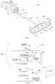
- FIG. 1illustrates a view of a portable device and a sensor, according to one example.
- FIG. 2illustrates a block diagram of a system, according to one example.
- FIG. 3illustrates a flow chart of a method executed by a system, according to one example.
- FIG. 1illustrates system 100 A including portable device 80 A and sensor 50 A, according to one example.
- Portable device 80 Aincludes a housing having connector 90 A.
- Connector 90 Ais coupled to the housing and is configured to mate with complementary connector 95 A, as shown by arrow A.
- Portable device 80 Aincludes elements 85 A, 85 B, 85 C, and 85 D on a surface of the housing.
- Elements 85 A, 85 B, 85 C, and 85 Dcan include user-operable controls or switches or can include visible indicators (such as a light emitting diode, LED, or a visible display).
- Elements 85 A, 85 B, 85 C, and 85 Dcan indicate a device condition (such as readiness for a measurement, battery charge state, or availability of wireless communication channel), or can indicate measured data corresponding to a signal from sensor 50 A.
- Connector 95 Ais coupled by link 60 A to sensor 50 A.
- Link 60 Ain one example, includes a length of flexible, multiconductor electric wire.
- Sensor 50 Aincludes at least one transducer configured to provide an electric signal corresponding to a measured parameter.
- the measured parametercan include regional oximetry, temperature, acceleration, pressure or other parameter.
- Other parameters or conditions that can be measured using a suitable transducer and programminginclude: regional saturation (rSO2); hemoglobin (Hb) concentration in tissue; tissue temperature; SpO 2 ; total hemoglobin (tHb); hematocrit; anemia; CO 2 ; COHb; MetHb; pH; respiration; perfusion; apnea; pulse wave velocity; blood pressure; interstitial pressure; arterial stiffness; intracranial pressure; intrauterine pressure/contractions; glucose; cardiac output; bilirubin; hydration; hematoma; vascular compliance; tissue viability; malaria; blood cancer; thrombocytopenia (low platelet count); sepsis; thrombosis; or compartment syndrome.
- rSO2regional saturation
- Hbhemoglobin
- tHbtotal hemoglobin
- a suitable algorithm executing on a processor and a suitable sensor modulecan provide data as to a material property of an object or as to a surface. This can include processing based on data corresponding to an optical measurement, a mechanical measurement, an acoustic measurement, or an electrical measurement.
- datacan correspond to an event counter, an event marker (time mark), a density measurement, a conductivity measurement, a concentration measurement, a color measurement, or a light level measurement.
- sensor 50 Aincludes contact surface 130 .
- Contact surface 130has a sensor module including emitter 138 A and emitter 138 B.
- Emitter 138 Aemits light into tissue that is received by detector 136 A along short pathway 140 A and light that is received by detector 136 B along long pathway 142 B.
- Emitter 138 Bemits light that is received by detector 136 B along short pathway 140 B and light that is received by detector 136 A along long pathway 142 A.
- Light received by detector 136 A and detector 136 B, using the combination of long pathway 142 A, long pathway 142 B, short pathway 140 A, and short pathway 140 Bcan be processed to generate a measure of regional oximetry (also called tissue oximetry). In one example, the calculation entails addition and subtraction of attenuations as detected by detector 136 A and detector 136 B.
- Detector 136 A and detector 136 Bcan include an optical transducer that provides an electrical signal corresponding to detected light.
- optical elementssuch as emitter 138 A, emitter 138 B, detector 136 A, and detector 136 B
- contact surface 130 Ais arranged such that emitter 138 A and emitter 138 B are at opposing ends and detector 136 A and detector 136 B are located there between.
- FIG. 2illustrates a block diagram of system 200 , according to one example.
- System 200includes system 100 B and remote device 70 .
- system 100 Bincludes sensor 50 B and portable device 80 B.
- Sensor 50 Bis coupled by link 60 B to connector 95 B.
- Connector 95 Bis configured to mate with complementary connector 90 B.
- Connector 90 Bis coupled to a housing of portable device 80 B.
- Portable device 80 Bincludes processor 205 .
- Processor 205is configured to receive an electrical signal from sensor 50 B and conducted by link 60 B, connector 95 B and connector 90 B.
- Processor 205can include a digital processor (such as a microprocessor) or an analog circuit.
- Processor 205is coupled to memory 215 .
- Memory 215provides storage for data and instructions. Data stored in memory 215 can include measured (or calculated) data, calibration parameters or coefficients. Instructions stored in memory 215 can cause processor 205 to implement an algorithm.
- the algorithmincludes selecting one of a plurality of calibration coefficients based on a particular identification signal corresponding to a particular sensor 50 B coupled to connector 90 B.
- I/O module 85can include user operable controls or switches and can include a visible display or indicator.
- Telemetry module 220is coupled to telemeter module 220 .
- Telemetry module 220sometimes referred to as a communication module, enable wireless communication of data or instructions between portable device 80 B and remote device 70 .
- Telemetry module 220is coupled to antenna 225 in the example shown.
- Telemetry module 220can include a radio frequency (RF) transceiver, an infrared communication module, or an ultrasound (or audio) communication module.
- RFradio frequency
- Power supply 230can include a rechargeable battery or a replaceable battery.
- Portable device 80 Bcan be configured as a hand-held device. In one example, portable device 80 B is less than several inches in length and has a connector on a surface.
- Remote device 70can include a portable or mobile computing device (such as a cellular telephone, a laptop computer, a tablet computer) or can include a desktop computer, workstation, or a server.
- a portable or mobile computing devicesuch as a cellular telephone, a laptop computer, a tablet computer
- a desktop computerworkstation, or a server.
- Remote device 70includes telemetry module 240 coupled to antenna 245 .
- Telemetry module 240(by way of antenna 245 ) is configured to communicate wirelessly with telemetry module 220 (by way of antenna 225 ).
- Telemetry module 240is coupled to processor 275 .
- Processor 275includes a digital processor.
- Processor 275is coupled to I/O module 290 and coupled to memory 285 .
- I/O module 290can include a touch-sensitive display, a keyboard, a mouse, or other user operable interface.
- I/O module 290can include a display, a network port, a printer, a speaker, or other output (or input/output) device.
- antenna 245 and telemetry module 240are coupled to a cloud or network 75 by link 260 .
- Network 75can include a wide area network or a local area network.
- FIG. 3illustrates flow chart 300 implemented by a system, according to one example.
- Flow chart 300includes, at 410 , pairing communication modules.
- thisentails establishing a wireless link between telemetry module 220 (and using antenna 225 ) and telemetry module 240 (and using antenna 245 ) in a process known as pairing.
- Pairingcan include exchanging access credentials and coordinating handshaking protocols.
- Some communication protocols, such as Bluetooth,are paired by executing a predetermined algorithm.
- method 300includes executing instructions to generate calculated data based on a measured signal from sensor 50 B.
- Thiscan include executing instructions (stored in memory 215 ) using processor 205 to implement an algorithm.
- the algorithmcan entail operating an emitter (such as emitter 138 A or emitter 138 B) according to a particular protocol and receiving an output signal from a detector (such as detector 136 A or detector 136 B). In one example, this can include receiving a temperature signal from a temperature transducer.
- method 300includes communicating the calculated data to remote device 70 .
- Communicatingcan include sending and receiving a wireless signal (using wireless telemetry modules).
- method 300includes executing instructions using processor 275 to generate a visible display of data.
- the datacan be displayed using I/O module 290 .
- datais communicated to network 75 by telemetry module 240 and antenna 245 or communicated to network 75 by a network connection of I/O module 290 .
- Example 1can include a system having a sensor, a second connector, a local processor, a first telemetry module, a second telemetry module, and a remote processor.
- the sensoris coupled to a cord.
- the cordhas a first connector.
- the second connectoris coupled to a housing.
- the second connectoris configured to mate with the first connector.
- the local processoris coupled to the second connector and is disposed in the housing.
- the local processoris configured to execute instructions stored in a local memory.
- the local memoryis disposed in the housing.
- the local processoris configured to generate calculated data based on a signal received at the second connector. The signal corresponds to a parameter measured by the sensor.
- the first telemetry moduleis coupled to the local processor and is configured to wirelessly communicate the calculated data.
- the second telemetry moduleis configured to communicate with the first telemetry module.
- the remote processoris coupled to the second telemetry module.
- the remote processoris configured to generate output data based on the calculated data.
- Example 2can include, or can optionally be combined with the subject matter of Example 1 to optionally include wherein the output data corresponds to regional oximetry.
- Example 3can include, or can optionally be combined with the subject matter of Example 1 to optionally include wherein the local processor is coupled to a user operable control.
- Example 4can include, or can optionally be combined with the subject matter of Example 1 to optionally include wherein the local processor is coupled to a visible display.
- Example 5can include, or can optionally be combined with the subject matter of Example 1 to optionally include wherein the local memory is configured to store the calculated data.
- Example 6can include, or can optionally be combined with the subject matter of Example 1 to optionally include wherein the first telemetry module includes a radio frequency transceiver.
- Example 7can include, or can optionally be combined with the subject matter of Example 1 to optionally include wherein the remote processor is configured to generate output data in near real-time relative to the signal.
- Example 8can include, or can optionally be combined with the subject matter of Example 1 to optionally include wherein the local memory is configured to store a plurality of calibration parameters and wherein the local processor is configured to select a particular calibration parameter from the plurality of calibration parameters, the particular calibration parameter corresponding to the sensor.
- Example 9can include, or can optionally be combined with the subject matter of Example 1 to optionally include wherein the sensor includes an optical element.
- Example 10can include, or can optionally be combined with the subject matter of Example 1 to optionally include wherein the local processor is coupled to a battery.
- Example 11can include, or can optionally be combined with the subject matter of Example 1 to optionally include wherein the housing is pocket-sized.
- Example 12can include, or can optionally be combined with the subject matter of Example 1 to optionally further include a cellular telephone and wherein at least one of the second telemetry module and the remote processor are included in the cellular telephone.
- Example 13can include a device having a first connector, a local processor, a local memory, and a local telemetry module.
- the first connectoris coupled to a housing.
- the first connectoris configured to mate with a sensor connector.
- the sensor connectoris coupled to an optical sensor.
- the local processoris coupled to the housing.
- the local memoryis coupled to the local processor.
- the local processoris configured to execute instructions stored in the local memory.
- the local processoris configured to generate calculated data based on a signal received at the first connector. The signal corresponds to a parameter measured by the optical sensor.
- the local telemetry moduleis coupled to the local processor and is configured to wirelessly communicate the calculated data.
- Example 14can include, or can optionally be combined with the subject matter of Example 13 to optionally include wherein the calculated data corresponds to regional oximetry.
- Example 15can include, or can optionally be combined with the subject matter of Example 13 to optionally include wherein the local processor is coupled to a user operable control.
- Example 16can include, or can optionally be combined with the subject matter of Example 13 to optionally include wherein the local processor is coupled to a visible display.
- Example 17can include, or can optionally be combined with the subject matter of Example 13 to optionally include wherein the local memory is configured to store the calculated data.
- Example 18can include, or can optionally be combined with the subject matter of Example 13 to optionally include wherein the local telemetry module includes a radio frequency transceiver.
- Example 19can include, or can optionally be combined with the subject matter of Example 13 to optionally include wherein the local telemetry module is configured to wirelessly communicate the calculated data in near real-time relative to the signal.
- Example 20can include, or can optionally be combined with the subject matter of Example 13 to optionally include wherein the local memory is configured to store a plurality of calibration parameters and wherein the local processor is configured to select a particular calibration parameter from the plurality of calibration parameters, the particular calibration parameter corresponding to the optical sensor.
- Example 21can include, or can optionally be combined with the subject matter of Example 13 to optionally include wherein the local processor is coupled to a battery.
- Example 22can include, or can optionally be combined with the subject matter of Example 13 to optionally include wherein the housing is pocket-sized.
- Example 23can include a method including pairing communication modules, executing instructions to generate calculated data, communicating the calculated data, and generating display data.
- the methodincludes pairing a first communication module of a remote computing device with a second communication module of a portable device.
- the portable devicehas a local connector configured to mate with a sensor connector.
- the sensor connectoris configured to provide a measured signal from an optical sensor.
- the local connectoris coupled to a local processor.
- the methodincludes executing instructions using the local processor.
- the instructionsare stored in a local memory.
- the instructionsare configured to generate calculated data based on the measured signal.
- the measured signalcorresponds to tissue at a contact surface of the optical sensor.
- the methodincludes communicating the calculated data to the remote computing device using the first communication module and using the second communication module.
- the methodincludes generating display data for a display of the remote computing device based on the calculated data.
- Example 24can include, or can optionally be combined with the subject matter of Example 23 to optionally include wherein executing the instructions using the local processor includes calculating a temperature using a temperature transducer.
- Example 25can include, or can optionally be combined with the subject matter of Example 23 to optionally include wherein executing the instructions using the local processor includes emitting light from the optical sensor.
- Example 26can include, or can optionally be combined with the subject matter of Example 23 to optionally include wherein executing instructions using the local processor includes calculating regional oximetry.
- Example 27can include, or can optionally be combined with the subject matter of Example 23 to optionally include displaying regional oximetry data based on the display data using the display.
- the terms “a” or “an”are used, as is common in patent documents, to include one or more than one, independent of any other instances or usages of “at least one” or “one or more.”
- the term “or”is used to refer to a nonexclusive or, such that “A or B” includes “A but not B,” “B but not A,” and “A and B,” unless otherwise indicated.
- Method examples described hereincan be machine or computer-implemented at least in part. Some examples can include a computer-readable medium or machine-readable medium encoded with instructions operable to configure an electronic device to perform methods as described in the above examples.
- An implementation of such methodscan include code, such as microcode, assembly language code, a higher-level language code, or the like. Such code can include computer readable instructions for performing various methods. The code may form portions of computer program products. Further, in an example, the code can be tangibly stored on one or more volatile, non-transitory, or non-volatile tangible computer-readable media, such as during execution or at other times.
- Examples of these tangible computer-readable mediacan include, but are not limited to, hard disks, removable magnetic disks, removable optical disks (e.g., compact disks and digital video disks), magnetic cassettes, memory cards or sticks, random access memories (RAMs), read only memories (ROMs), and the like.
Landscapes
- Health & Medical Sciences (AREA)
- Life Sciences & Earth Sciences (AREA)
- Physics & Mathematics (AREA)
- Cardiology (AREA)
- Medical Informatics (AREA)
- Animal Behavior & Ethology (AREA)
- Pathology (AREA)
- Engineering & Computer Science (AREA)
- Biomedical Technology (AREA)
- Heart & Thoracic Surgery (AREA)
- Veterinary Medicine (AREA)
- Molecular Biology (AREA)
- Surgery (AREA)
- Biophysics (AREA)
- General Health & Medical Sciences (AREA)
- Public Health (AREA)
- Physiology (AREA)
- Optics & Photonics (AREA)
- Spectroscopy & Molecular Physics (AREA)
- Pulmonology (AREA)
- Measuring And Recording Apparatus For Diagnosis (AREA)
- Measurement Of The Respiration, Hearing Ability, Form, And Blood Characteristics Of Living Organisms (AREA)
Abstract
Description
Claims (18)
Priority Applications (1)
| Application Number | Priority Date | Filing Date | Title |
|---|---|---|---|
| US14/082,975US11179075B2 (en) | 2013-11-18 | 2013-11-18 | Regional oximetry sensor interface |
Applications Claiming Priority (1)
| Application Number | Priority Date | Filing Date | Title |
|---|---|---|---|
| US14/082,975US11179075B2 (en) | 2013-11-18 | 2013-11-18 | Regional oximetry sensor interface |
Publications (2)
| Publication Number | Publication Date |
|---|---|
| US20150141780A1 US20150141780A1 (en) | 2015-05-21 |
| US11179075B2true US11179075B2 (en) | 2021-11-23 |
Family
ID=53173977
Family Applications (1)
| Application Number | Title | Priority Date | Filing Date |
|---|---|---|---|
| US14/082,975ActiveUS11179075B2 (en) | 2013-11-18 | 2013-11-18 | Regional oximetry sensor interface |
Country Status (1)
| Country | Link |
|---|---|
| US (1) | US11179075B2 (en) |
Cited By (1)
| Publication number | Priority date | Publication date | Assignee | Title |
|---|---|---|---|---|
| US20220336943A1 (en)* | 2021-04-19 | 2022-10-20 | Milwaukee Electric Tool Corporation | Systems and Methods for Tool Signal Extension |
Families Citing this family (7)
| Publication number | Priority date | Publication date | Assignee | Title |
|---|---|---|---|---|
| US6850788B2 (en) | 2002-03-25 | 2005-02-01 | Masimo Corporation | Physiological measurement communications adapter |
| US10188329B2 (en) | 2013-03-14 | 2019-01-29 | Nonin Medical, Inc. | Self-contained regional oximetry |
| US9895090B2 (en) | 2013-11-18 | 2018-02-20 | Nonin Medical, Inc. | Regional oximetry sleeve for mobile device |
| JP7146733B2 (en) | 2016-07-18 | 2022-10-04 | ビオプティックス・インコーポレイテッド | Oxygen measurement device with laparoscopic dilation |
| US11350860B1 (en)* | 2016-09-23 | 2022-06-07 | Apple Inc. | Wrist-worn device and method for accurate blood oxygen saturation measurement |
| CN108784710A (en)* | 2018-06-27 | 2018-11-13 | 常州市第人民医院 | A kind of blood oxygen saturation monitoring instrument based on Radio Transmission Technology |
| WO2020069229A1 (en)* | 2018-09-27 | 2020-04-02 | Odin Technologies, Llc | Non-invasive device and methods for monitoring muscle tissue condition |
Citations (25)
| Publication number | Priority date | Publication date | Assignee | Title |
|---|---|---|---|---|
| US5810724A (en) | 1995-12-01 | 1998-09-22 | Nellcor Puritan Bennett Incorporated | Reusable sensor accessory containing a conformable spring activated rubber sleeved clip |
| US20020082489A1 (en) | 1994-04-01 | 2002-06-27 | Casciani James R. | Pulse oximeter and sensor optimized for low saturation |
| US20020116797A1 (en) | 2000-02-17 | 2002-08-29 | Modgil Onkar S. | Apparatus and method for securing an oximeter probe to a patient |
| US6622034B1 (en) | 1999-09-10 | 2003-09-16 | Imagenix, Inc. | Oximeter sensor with functional liner |
| US20030181798A1 (en)* | 2002-03-25 | 2003-09-25 | Ammar Al-Ali | Physiological measurement communications adapter |
| US20060238358A1 (en)* | 2005-03-01 | 2006-10-26 | Ammar Al-Ali | Noninvasive multi-parameter patient monitor |
| US20080139908A1 (en) | 2005-05-13 | 2008-06-12 | Charles Dean Kurth | Multi-Wavelength Spatial Domain Near Infrared Oximeter to Detect Cerebral Hypoxia-Ischemia |
| US20090105605A1 (en)* | 2003-04-22 | 2009-04-23 | Marcio Marc Abreu | Apparatus and method for measuring biologic parameters |
| US20090163787A1 (en) | 2007-12-21 | 2009-06-25 | Nellcor Puritan Bennett Llc | Medical sensor and technique for using the same |
| US20100010326A1 (en) | 2008-07-03 | 2010-01-14 | Masimo Laboratories, Inc. | Contoured protrusion for improving spectroscopic measurement of blood constituents |
| US7671351B2 (en) | 2003-09-05 | 2010-03-02 | Authentec, Inc. | Finger sensor using optical dispersion sensing and associated methods |
| US20100125188A1 (en)* | 2008-11-18 | 2010-05-20 | Nonin Medical, Inc. | Motion correlated pulse oximetry |
| US20100240972A1 (en) | 2009-03-20 | 2010-09-23 | Nellcor Puritan Bennett Llc | Slider Spot Check Pulse Oximeter |
| US20100312080A1 (en) | 2009-06-05 | 2010-12-09 | Nonin Medical, Inc. | Regional oximetry analog front end |
| US20100331631A1 (en)* | 2009-06-30 | 2010-12-30 | Nellcor Puritan Bennett Llc | Oxygen saturation ear sensor design that optimizes both attachment method and signal quality |
| US20110077473A1 (en)* | 2009-09-29 | 2011-03-31 | Nellcor Puritan Bennett Llc | Patient sensor intercommunication circuitry for a medical monitor |
| US20110112387A1 (en)* | 2009-11-12 | 2011-05-12 | Nellcor Puritan Bennett Llc | Simultaneous measurement of pulse and regional blood oxygen saturation |
| US20110224518A1 (en) | 2008-07-22 | 2011-09-15 | Jaafar Tindi | Handheld apparatus to determine the viability of a biological tissue |
| US20120059267A1 (en) | 2010-08-26 | 2012-03-08 | Masimo Corporation | Blood pressure measurement system |
| US8301232B2 (en) | 2010-06-08 | 2012-10-30 | Alivecor, Inc. | Wireless, ultrasonic personal health monitoring system |
| US20140200054A1 (en) | 2013-01-14 | 2014-07-17 | Fraden Corp. | Sensing case for a mobile communication device |
| US20140275885A1 (en) | 2013-03-14 | 2014-09-18 | Nonin Medical, Inc. | Self-contained regional oximetry |
| US20150099951A1 (en)* | 2013-10-07 | 2015-04-09 | Masimo Corporation | Regional oximetry pod |
| US20150141779A1 (en) | 2013-11-18 | 2015-05-21 | Nonin Medical, Inc. | Regional oximetry sleeve for mobile device |
| US9693697B2 (en) | 2012-03-29 | 2017-07-04 | Benny Tal | Hand-held device having health monitoring capabilities |
- 2013
- 2013-11-18USUS14/082,975patent/US11179075B2/enactiveActive
Patent Citations (31)
| Publication number | Priority date | Publication date | Assignee | Title |
|---|---|---|---|---|
| US20020082489A1 (en) | 1994-04-01 | 2002-06-27 | Casciani James R. | Pulse oximeter and sensor optimized for low saturation |
| US5810724A (en) | 1995-12-01 | 1998-09-22 | Nellcor Puritan Bennett Incorporated | Reusable sensor accessory containing a conformable spring activated rubber sleeved clip |
| US6622034B1 (en) | 1999-09-10 | 2003-09-16 | Imagenix, Inc. | Oximeter sensor with functional liner |
| US20020116797A1 (en) | 2000-02-17 | 2002-08-29 | Modgil Onkar S. | Apparatus and method for securing an oximeter probe to a patient |
| US20030181798A1 (en)* | 2002-03-25 | 2003-09-25 | Ammar Al-Ali | Physiological measurement communications adapter |
| US7844315B2 (en)* | 2002-03-25 | 2010-11-30 | Masimo Corporation | Physiological measurement communications adapter |
| US20090105605A1 (en)* | 2003-04-22 | 2009-04-23 | Marcio Marc Abreu | Apparatus and method for measuring biologic parameters |
| US7671351B2 (en) | 2003-09-05 | 2010-03-02 | Authentec, Inc. | Finger sensor using optical dispersion sensing and associated methods |
| US20060238358A1 (en)* | 2005-03-01 | 2006-10-26 | Ammar Al-Ali | Noninvasive multi-parameter patient monitor |
| US20080139908A1 (en) | 2005-05-13 | 2008-06-12 | Charles Dean Kurth | Multi-Wavelength Spatial Domain Near Infrared Oximeter to Detect Cerebral Hypoxia-Ischemia |
| US20090163787A1 (en) | 2007-12-21 | 2009-06-25 | Nellcor Puritan Bennett Llc | Medical sensor and technique for using the same |
| US20100010326A1 (en) | 2008-07-03 | 2010-01-14 | Masimo Laboratories, Inc. | Contoured protrusion for improving spectroscopic measurement of blood constituents |
| US20110224518A1 (en) | 2008-07-22 | 2011-09-15 | Jaafar Tindi | Handheld apparatus to determine the viability of a biological tissue |
| US20100125188A1 (en)* | 2008-11-18 | 2010-05-20 | Nonin Medical, Inc. | Motion correlated pulse oximetry |
| US20100240972A1 (en) | 2009-03-20 | 2010-09-23 | Nellcor Puritan Bennett Llc | Slider Spot Check Pulse Oximeter |
| US20100312080A1 (en) | 2009-06-05 | 2010-12-09 | Nonin Medical, Inc. | Regional oximetry analog front end |
| US20100331631A1 (en)* | 2009-06-30 | 2010-12-30 | Nellcor Puritan Bennett Llc | Oxygen saturation ear sensor design that optimizes both attachment method and signal quality |
| US20110077473A1 (en)* | 2009-09-29 | 2011-03-31 | Nellcor Puritan Bennett Llc | Patient sensor intercommunication circuitry for a medical monitor |
| US20110112387A1 (en)* | 2009-11-12 | 2011-05-12 | Nellcor Puritan Bennett Llc | Simultaneous measurement of pulse and regional blood oxygen saturation |
| US8301232B2 (en) | 2010-06-08 | 2012-10-30 | Alivecor, Inc. | Wireless, ultrasonic personal health monitoring system |
| US20120059267A1 (en) | 2010-08-26 | 2012-03-08 | Masimo Corporation | Blood pressure measurement system |
| US9693697B2 (en) | 2012-03-29 | 2017-07-04 | Benny Tal | Hand-held device having health monitoring capabilities |
| US20140200054A1 (en) | 2013-01-14 | 2014-07-17 | Fraden Corp. | Sensing case for a mobile communication device |
| US20140275885A1 (en) | 2013-03-14 | 2014-09-18 | Nonin Medical, Inc. | Self-contained regional oximetry |
| WO2014159723A2 (en) | 2013-03-14 | 2014-10-02 | Nonin Medical, Inc. | Self-contained regional oximetry |
| US10188329B2 (en) | 2013-03-14 | 2019-01-29 | Nonin Medical, Inc. | Self-contained regional oximetry |
| US20150099951A1 (en)* | 2013-10-07 | 2015-04-09 | Masimo Corporation | Regional oximetry pod |
| US20150141779A1 (en) | 2013-11-18 | 2015-05-21 | Nonin Medical, Inc. | Regional oximetry sleeve for mobile device |
| US9895090B2 (en) | 2013-11-18 | 2018-02-20 | Nonin Medical, Inc. | Regional oximetry sleeve for mobile device |
| US20180140238A1 (en) | 2013-11-18 | 2018-05-24 | Nonin Medical, Inc. | Regional oximetry sleeve for mobile device |
| US10709368B2 (en) | 2013-11-18 | 2020-07-14 | Nonin Medical, Inc. | Regional oximetry sleeve for mobile device |
Non-Patent Citations (33)
| Title |
|---|
| "Eropean Application Serial No. 14775821.3, Extended European Search Report dated Oct. 18, 2016", 8 pgs. |
| "U.S. Appl. No. 13/829,158, Examiner Interview Summary dated Dec. 19, 2016", 4 pgs. |
| "U.S. Appl. No. 13/829,158, Non Final Office Action dated Feb. 22, 2017", 12 pgs. |
| "U.S. Appl. No. 13/829,158, Notice of Allowance dated Sep. 19, 2018", 9 pgs. |
| "U.S. Appl. No. 13/829,158, Response filed Jan. 30, 2017 to Final Office Action dated Jul. 18, 2016", 16 pgs. |
| "U.S. Appl. No. 13/829,158, Response fled Apr. 16, 2018 to Non Final Office Action dated Dec. 15, 2017", 12 pgs. |
| "U.S. Appl. No. 14/082,950, Advisory Action dated Feb. 8, 2017", 3 pgs. |
| "U.S. Appl. No. 14/082,950, Non Final Office Action dated Mar. 7, 2017", 13 pgs. |
| "U.S. Appl. No. 14/082,950, Response filed Feb. 16, 2017 to Advisory Action dated Feb. 8, 2017", 16 pgs. |
| "U.S. Appl. No. 14/082,950, Response filed Jan. 17, 2017 to Final Office Action dated Aug. 16, 2016", 13 pgs. |
| "U.S. Appl. No. 15/872,779, Non Final Office Action dated Jun. 27, 2019", 6 pgs. |
| Application Serial No. PCT/US2014/024906, International Preliminary Report on Patentability dated Sep. 24, 2015, 7 pgs. |
| European Application Serial No. 14775821.3, Response filed May 2, 2016 to Communication pursuant to Rules 161(2) and 162 EPC dated Oct. 22, 2015, 14 pgs. |
| International Application Serial No. PCT/US2014/024906, International Search Report dated Sep. 16, 2014, 2 pgs. |
| International Application Serial No. PCT/US2014/024906, Written Opinion dated Sep. 16, 2014, 5 pgs. |
| U.S. Appl. No. 13/829,158, Final Office Action dated Jan. 4, 2016, 12 pgs. |
| U.S. Appl. No. 13/829,158, Final Office Action dated Jul. 28, 2016, 13 pgs. |
| U.S. Appl. No. 13/829,158, Non Final Office Action dated Dec. 15, 2017, 6 pgs. |
| U.S. Appl. No. 13/829,158, Non Final Office Action dated Jul. 6, 2015, 11 pgs. |
| U.S. Appl. No. 13/829,158, Response filed Aug. 22, 2017 to Non Final Office Action dated Feb. 22, 2017, 18 pgs. |
| U.S. Appl. No. 13/829,158, Response filed Dec. 7, 2015 to Non Final Office Action dated Jul. 6, 2015, 12 pgs. |
| U.S. Appl. No. 13/829,158, Response filed Jul. 5, 2016 to Final Office Action dated Jan. 4, 2016, 10 pgs. |
| U.S. Appl. No. 14/082,950 Examiner Interview Summary dated Jun. 22, 2017, 3 pgs. |
| U.S. Appl. No. 14/082,950, Final Office Action dated Aug. 16, 2016, 11 pgs. |
| U.S. Appl. No. 14/082,950, Non Final Office Action dated Dec. 16, 2015, 14 pgs. |
| U.S. Appl. No. 14/082,950, Notice of Allowance dated Oct. 5, 2017, 7 pgs. |
| U.S. Appl. No. 14/082,950, Response filed Aug. 7, 2017 to Non Final Office Action dated Mar. 7, 2017, 15 pgs. |
| U.S. Appl. No. 14/082,950, Response filed Jun. 16, 2016 to Non Final Office Action dated Dec. 16, 2015, 11 pgs. |
| U.S. Appl. No. 15/872,779, filed Jan. 16, 2018, Regional Oximetry Sleeve for Mobile Device. |
| U.S. Appl. No. 15/872,779, Notice of Allowance dated Mar. 10, 2020, 5 pgs. |
| U.S. Appl. No. 15/872,779, Response filed Dec. 27, 2019 to Non Final Office Action dated Jun. 27, 2019, 5 pgs. |
| U.S. Appl. No. 16/235,884, filed Dec. 28, 2018, Self-Contained Regional Oximetry. |
| U.S. Appl. No. 16/903,283, filed Jun. 16, 2020, Regional Oximetry Sleeve for Mobile Device. |
Cited By (2)
| Publication number | Priority date | Publication date | Assignee | Title |
|---|---|---|---|---|
| US20220336943A1 (en)* | 2021-04-19 | 2022-10-20 | Milwaukee Electric Tool Corporation | Systems and Methods for Tool Signal Extension |
| US12170396B2 (en)* | 2021-04-19 | 2024-12-17 | Milwaukee Electric Tool Corporation | Systems and methods for tool signal extension |
Also Published As
| Publication number | Publication date |
|---|---|
| US20150141780A1 (en) | 2015-05-21 |
Similar Documents
| Publication | Publication Date | Title |
|---|---|---|
| US11179075B2 (en) | Regional oximetry sensor interface | |
| US10709368B2 (en) | Regional oximetry sleeve for mobile device | |
| US10188329B2 (en) | Self-contained regional oximetry | |
| US11064948B2 (en) | Medical diagnostic device, system, and method of use | |
| US8740792B1 (en) | Patient monitor capable of accounting for environmental conditions | |
| US9364185B2 (en) | Low energy wireless communication systems and methods for medical devices | |
| US20150190099A1 (en) | Biological information processing system, biological information measurement device, control device, method of controlling them and storage medium | |
| US10251607B2 (en) | Method and apparatus for measuring bio signal | |
| EP3613340A1 (en) | Apparatus and method for estimating blood pressure | |
| US20140046199A1 (en) | Method for measuring human vital signs and portable terminal adopting the same | |
| US20250275692A1 (en) | Systems, devices, and methods for sensor fault detection | |
| US10674961B2 (en) | Universal fingertip sensor | |
| US20140350367A1 (en) | Peak flow meter, breathalyzer, and pulse oximeter for use with a mobile device | |
| CN105520723B (en) | Vital sign measurement device, vital sign display method, and program | |
| Karthi et al. | Smart health surveillance with automated database using android mobile device | |
| KR20200004165A (en) | Flexible patch apparatus integrated with multi-sensors for multi-biological signal detection and method for detecting multi-biological signal using the flexible patch apparatus | |
| JP2016158720A (en) | Biological information monitor | |
| US20200322064A1 (en) | Wireless Sensors in Medical Environments | |
| CN102247125A (en) | Electronic wrist strap for living body wearing detection through vital signs | |
| CN203455303U (en) | Biological characteristic sensing system, biological characteristic sensing test piece and measuring device | |
| Hemalatha | IoT based Health Monitoring System | |
| KR102458207B1 (en) | Composite Information Analysis Device and Method with Bio Signal and Multi Channel Environment Information Acquisition | |
| JP6491383B1 (en) | Blood flow measurement system | |
| CN207590667U (en) | Monitoring system | |
| CN103646124A (en) | Data reading and analyzing device of family medical detecting instrument |
Legal Events
| Date | Code | Title | Description |
|---|---|---|---|
| AS | Assignment | Owner name:NONIN MEDICAL, INC., MINNESOTA Free format text:ASSIGNMENT OF ASSIGNORS INTEREST;ASSIGNORS:MEYER, DAVID A.;JOHNSON, TIMOTHY L.;JONES, BRYANT AUSTIN;SIGNING DATES FROM 20150904 TO 20150908;REEL/FRAME:037833/0049 | |
| STPP | Information on status: patent application and granting procedure in general | Free format text:NON FINAL ACTION MAILED | |
| STPP | Information on status: patent application and granting procedure in general | Free format text:RESPONSE TO NON-FINAL OFFICE ACTION ENTERED AND FORWARDED TO EXAMINER | |
| STPP | Information on status: patent application and granting procedure in general | Free format text:FINAL REJECTION MAILED | |
| STPP | Information on status: patent application and granting procedure in general | Free format text:NON FINAL ACTION MAILED | |
| FEPP | Fee payment procedure | Free format text:PETITION RELATED TO MAINTENANCE FEES GRANTED (ORIGINAL EVENT CODE: PTGR); ENTITY STATUS OF PATENT OWNER: SMALL ENTITY | |
| STPP | Information on status: patent application and granting procedure in general | Free format text:RESPONSE TO NON-FINAL OFFICE ACTION ENTERED AND FORWARDED TO EXAMINER | |
| STPP | Information on status: patent application and granting procedure in general | Free format text:NOTICE OF ALLOWANCE MAILED -- APPLICATION RECEIVED IN OFFICE OF PUBLICATIONS | |
| STPP | Information on status: patent application and granting procedure in general | Free format text:PUBLICATIONS -- ISSUE FEE PAYMENT RECEIVED | |
| STPP | Information on status: patent application and granting procedure in general | Free format text:PUBLICATIONS -- ISSUE FEE PAYMENT VERIFIED | |
| STCF | Information on status: patent grant | Free format text:PATENTED CASE | |
| MAFP | Maintenance fee payment | Free format text:PAYMENT OF MAINTENANCE FEE, 4TH YR, SMALL ENTITY (ORIGINAL EVENT CODE: M2551); ENTITY STATUS OF PATENT OWNER: SMALL ENTITY Year of fee payment:4 |