US11175386B2 - Ladar system with adaptive receiver - Google Patents
Ladar system with adaptive receiverDownload PDFInfo
- Publication number
- US11175386B2 US11175386B2US17/024,014US202017024014AUS11175386B2US 11175386 B2US11175386 B2US 11175386B2US 202017024014 AUS202017024014 AUS 202017024014AUS 11175386 B2US11175386 B2US 11175386B2
- Authority
- US
- United States
- Prior art keywords
- ladar
- mirror
- pixels
- light
- range
- Prior art date
- Legal status (The legal status is an assumption and is not a legal conclusion. Google has not performed a legal analysis and makes no representation as to the accuracy of the status listed.)
- Active
Links
Images


Classifications
- G—PHYSICS
- G01—MEASURING; TESTING
- G01S—RADIO DIRECTION-FINDING; RADIO NAVIGATION; DETERMINING DISTANCE OR VELOCITY BY USE OF RADIO WAVES; LOCATING OR PRESENCE-DETECTING BY USE OF THE REFLECTION OR RERADIATION OF RADIO WAVES; ANALOGOUS ARRANGEMENTS USING OTHER WAVES
- G01S7/00—Details of systems according to groups G01S13/00, G01S15/00, G01S17/00
- G01S7/48—Details of systems according to groups G01S13/00, G01S15/00, G01S17/00 of systems according to group G01S17/00
- G01S7/483—Details of pulse systems
- G01S7/486—Receivers
- G01S7/4861—Circuits for detection, sampling, integration or read-out
- G01S7/4863—Detector arrays, e.g. charge-transfer gates
- G—PHYSICS
- G01—MEASURING; TESTING
- G01S—RADIO DIRECTION-FINDING; RADIO NAVIGATION; DETERMINING DISTANCE OR VELOCITY BY USE OF RADIO WAVES; LOCATING OR PRESENCE-DETECTING BY USE OF THE REFLECTION OR RERADIATION OF RADIO WAVES; ANALOGOUS ARRANGEMENTS USING OTHER WAVES
- G01S17/00—Systems using the reflection or reradiation of electromagnetic waves other than radio waves, e.g. lidar systems
- G01S17/02—Systems using the reflection of electromagnetic waves other than radio waves
- G01S17/06—Systems determining position data of a target
- G01S17/08—Systems determining position data of a target for measuring distance only
- G01S17/10—Systems determining position data of a target for measuring distance only using transmission of interrupted, pulse-modulated waves
- G—PHYSICS
- G01—MEASURING; TESTING
- G01S—RADIO DIRECTION-FINDING; RADIO NAVIGATION; DETERMINING DISTANCE OR VELOCITY BY USE OF RADIO WAVES; LOCATING OR PRESENCE-DETECTING BY USE OF THE REFLECTION OR RERADIATION OF RADIO WAVES; ANALOGOUS ARRANGEMENTS USING OTHER WAVES
- G01S17/00—Systems using the reflection or reradiation of electromagnetic waves other than radio waves, e.g. lidar systems
- G01S17/02—Systems using the reflection of electromagnetic waves other than radio waves
- G01S17/06—Systems determining position data of a target
- G01S17/42—Simultaneous measurement of distance and other co-ordinates
- G—PHYSICS
- G01—MEASURING; TESTING
- G01S—RADIO DIRECTION-FINDING; RADIO NAVIGATION; DETERMINING DISTANCE OR VELOCITY BY USE OF RADIO WAVES; LOCATING OR PRESENCE-DETECTING BY USE OF THE REFLECTION OR RERADIATION OF RADIO WAVES; ANALOGOUS ARRANGEMENTS USING OTHER WAVES
- G01S17/00—Systems using the reflection or reradiation of electromagnetic waves other than radio waves, e.g. lidar systems
- G01S17/66—Tracking systems using electromagnetic waves other than radio waves
- G—PHYSICS
- G01—MEASURING; TESTING
- G01S—RADIO DIRECTION-FINDING; RADIO NAVIGATION; DETERMINING DISTANCE OR VELOCITY BY USE OF RADIO WAVES; LOCATING OR PRESENCE-DETECTING BY USE OF THE REFLECTION OR RERADIATION OF RADIO WAVES; ANALOGOUS ARRANGEMENTS USING OTHER WAVES
- G01S17/00—Systems using the reflection or reradiation of electromagnetic waves other than radio waves, e.g. lidar systems
- G01S17/88—Lidar systems specially adapted for specific applications
- G01S17/89—Lidar systems specially adapted for specific applications for mapping or imaging
- G—PHYSICS
- G01—MEASURING; TESTING
- G01S—RADIO DIRECTION-FINDING; RADIO NAVIGATION; DETERMINING DISTANCE OR VELOCITY BY USE OF RADIO WAVES; LOCATING OR PRESENCE-DETECTING BY USE OF THE REFLECTION OR RERADIATION OF RADIO WAVES; ANALOGOUS ARRANGEMENTS USING OTHER WAVES
- G01S7/00—Details of systems according to groups G01S13/00, G01S15/00, G01S17/00
- G01S7/48—Details of systems according to groups G01S13/00, G01S15/00, G01S17/00 of systems according to group G01S17/00
- G01S7/481—Constructional features, e.g. arrangements of optical elements
- G01S7/4811—Constructional features, e.g. arrangements of optical elements common to transmitter and receiver
- G01S7/4813—Housing arrangements
- G—PHYSICS
- G01—MEASURING; TESTING
- G01S—RADIO DIRECTION-FINDING; RADIO NAVIGATION; DETERMINING DISTANCE OR VELOCITY BY USE OF RADIO WAVES; LOCATING OR PRESENCE-DETECTING BY USE OF THE REFLECTION OR RERADIATION OF RADIO WAVES; ANALOGOUS ARRANGEMENTS USING OTHER WAVES
- G01S7/00—Details of systems according to groups G01S13/00, G01S15/00, G01S17/00
- G01S7/48—Details of systems according to groups G01S13/00, G01S15/00, G01S17/00 of systems according to group G01S17/00
- G01S7/481—Constructional features, e.g. arrangements of optical elements
- G01S7/4814—Constructional features, e.g. arrangements of optical elements of transmitters alone
- G01S7/4815—Constructional features, e.g. arrangements of optical elements of transmitters alone using multiple transmitters
- G—PHYSICS
- G01—MEASURING; TESTING
- G01S—RADIO DIRECTION-FINDING; RADIO NAVIGATION; DETERMINING DISTANCE OR VELOCITY BY USE OF RADIO WAVES; LOCATING OR PRESENCE-DETECTING BY USE OF THE REFLECTION OR RERADIATION OF RADIO WAVES; ANALOGOUS ARRANGEMENTS USING OTHER WAVES
- G01S7/00—Details of systems according to groups G01S13/00, G01S15/00, G01S17/00
- G01S7/48—Details of systems according to groups G01S13/00, G01S15/00, G01S17/00 of systems according to group G01S17/00
- G01S7/481—Constructional features, e.g. arrangements of optical elements
- G01S7/4816—Constructional features, e.g. arrangements of optical elements of receivers alone
- G—PHYSICS
- G01—MEASURING; TESTING
- G01S—RADIO DIRECTION-FINDING; RADIO NAVIGATION; DETERMINING DISTANCE OR VELOCITY BY USE OF RADIO WAVES; LOCATING OR PRESENCE-DETECTING BY USE OF THE REFLECTION OR RERADIATION OF RADIO WAVES; ANALOGOUS ARRANGEMENTS USING OTHER WAVES
- G01S7/00—Details of systems according to groups G01S13/00, G01S15/00, G01S17/00
- G01S7/48—Details of systems according to groups G01S13/00, G01S15/00, G01S17/00 of systems according to group G01S17/00
- G01S7/481—Constructional features, e.g. arrangements of optical elements
- G01S7/4817—Constructional features, e.g. arrangements of optical elements relating to scanning
- G—PHYSICS
- G01—MEASURING; TESTING
- G01S—RADIO DIRECTION-FINDING; RADIO NAVIGATION; DETERMINING DISTANCE OR VELOCITY BY USE OF RADIO WAVES; LOCATING OR PRESENCE-DETECTING BY USE OF THE REFLECTION OR RERADIATION OF RADIO WAVES; ANALOGOUS ARRANGEMENTS USING OTHER WAVES
- G01S7/00—Details of systems according to groups G01S13/00, G01S15/00, G01S17/00
- G01S7/48—Details of systems according to groups G01S13/00, G01S15/00, G01S17/00 of systems according to group G01S17/00
- G01S7/481—Constructional features, e.g. arrangements of optical elements
- G01S7/4818—Constructional features, e.g. arrangements of optical elements using optical fibres
- G—PHYSICS
- G01—MEASURING; TESTING
- G01S—RADIO DIRECTION-FINDING; RADIO NAVIGATION; DETERMINING DISTANCE OR VELOCITY BY USE OF RADIO WAVES; LOCATING OR PRESENCE-DETECTING BY USE OF THE REFLECTION OR RERADIATION OF RADIO WAVES; ANALOGOUS ARRANGEMENTS USING OTHER WAVES
- G01S7/00—Details of systems according to groups G01S13/00, G01S15/00, G01S17/00
- G01S7/48—Details of systems according to groups G01S13/00, G01S15/00, G01S17/00 of systems according to group G01S17/00
- G01S7/483—Details of pulse systems
- G01S7/486—Receivers
- G01S7/4865—Time delay measurement, e.g. time-of-flight measurement, time of arrival measurement or determining the exact position of a peak
- G—PHYSICS
- G01—MEASURING; TESTING
- G01S—RADIO DIRECTION-FINDING; RADIO NAVIGATION; DETERMINING DISTANCE OR VELOCITY BY USE OF RADIO WAVES; LOCATING OR PRESENCE-DETECTING BY USE OF THE REFLECTION OR RERADIATION OF RADIO WAVES; ANALOGOUS ARRANGEMENTS USING OTHER WAVES
- G01S7/00—Details of systems according to groups G01S13/00, G01S15/00, G01S17/00
- G01S7/48—Details of systems according to groups G01S13/00, G01S15/00, G01S17/00 of systems according to group G01S17/00
- G01S7/483—Details of pulse systems
- G01S7/486—Receivers
- G01S7/487—Extracting wanted echo signals, e.g. pulse detection
- G—PHYSICS
- G01—MEASURING; TESTING
- G01S—RADIO DIRECTION-FINDING; RADIO NAVIGATION; DETERMINING DISTANCE OR VELOCITY BY USE OF RADIO WAVES; LOCATING OR PRESENCE-DETECTING BY USE OF THE REFLECTION OR RERADIATION OF RADIO WAVES; ANALOGOUS ARRANGEMENTS USING OTHER WAVES
- G01S7/00—Details of systems according to groups G01S13/00, G01S15/00, G01S17/00
- G01S7/48—Details of systems according to groups G01S13/00, G01S15/00, G01S17/00 of systems according to group G01S17/00
- G01S7/483—Details of pulse systems
- G01S7/486—Receivers
- G01S7/489—Gain of receiver varied automatically during pulse-recurrence period
- G—PHYSICS
- G01—MEASURING; TESTING
- G01S—RADIO DIRECTION-FINDING; RADIO NAVIGATION; DETERMINING DISTANCE OR VELOCITY BY USE OF RADIO WAVES; LOCATING OR PRESENCE-DETECTING BY USE OF THE REFLECTION OR RERADIATION OF RADIO WAVES; ANALOGOUS ARRANGEMENTS USING OTHER WAVES
- G01S7/00—Details of systems according to groups G01S13/00, G01S15/00, G01S17/00
- G01S7/48—Details of systems according to groups G01S13/00, G01S15/00, G01S17/00 of systems according to group G01S17/00
- G01S7/497—Means for monitoring or calibrating
- G—PHYSICS
- G01—MEASURING; TESTING
- G01S—RADIO DIRECTION-FINDING; RADIO NAVIGATION; DETERMINING DISTANCE OR VELOCITY BY USE OF RADIO WAVES; LOCATING OR PRESENCE-DETECTING BY USE OF THE REFLECTION OR RERADIATION OF RADIO WAVES; ANALOGOUS ARRANGEMENTS USING OTHER WAVES
- G01S17/00—Systems using the reflection or reradiation of electromagnetic waves other than radio waves, e.g. lidar systems
- G01S17/02—Systems using the reflection of electromagnetic waves other than radio waves
- G01S17/06—Systems determining position data of a target
- G01S17/08—Systems determining position data of a target for measuring distance only
- G01S17/10—Systems determining position data of a target for measuring distance only using transmission of interrupted, pulse-modulated waves
- G01S17/26—Systems determining position data of a target for measuring distance only using transmission of interrupted, pulse-modulated waves wherein the transmitted pulses use a frequency-modulated or phase-modulated carrier wave, e.g. for pulse compression of received signals
- G—PHYSICS
- G01—MEASURING; TESTING
- G01S—RADIO DIRECTION-FINDING; RADIO NAVIGATION; DETERMINING DISTANCE OR VELOCITY BY USE OF RADIO WAVES; LOCATING OR PRESENCE-DETECTING BY USE OF THE REFLECTION OR RERADIATION OF RADIO WAVES; ANALOGOUS ARRANGEMENTS USING OTHER WAVES
- G01S17/00—Systems using the reflection or reradiation of electromagnetic waves other than radio waves, e.g. lidar systems
- G01S17/88—Lidar systems specially adapted for specific applications
- G01S17/93—Lidar systems specially adapted for specific applications for anti-collision purposes
- G01S17/931—Lidar systems specially adapted for specific applications for anti-collision purposes of land vehicles
- G—PHYSICS
- G01—MEASURING; TESTING
- G01S—RADIO DIRECTION-FINDING; RADIO NAVIGATION; DETERMINING DISTANCE OR VELOCITY BY USE OF RADIO WAVES; LOCATING OR PRESENCE-DETECTING BY USE OF THE REFLECTION OR RERADIATION OF RADIO WAVES; ANALOGOUS ARRANGEMENTS USING OTHER WAVES
- G01S7/00—Details of systems according to groups G01S13/00, G01S15/00, G01S17/00
- G01S7/48—Details of systems according to groups G01S13/00, G01S15/00, G01S17/00 of systems according to group G01S17/00
- G01S7/483—Details of pulse systems
- G01S7/486—Receivers
- G01S7/487—Extracting wanted echo signals, e.g. pulse detection
- G01S7/4876—Extracting wanted echo signals, e.g. pulse detection by removing unwanted signals
Definitions
- autonomous platform visione.g., autonomous vehicles for air, land (including underground), water (including underwater), and space, such as autonomous land-based vehicles, autonomous aerial vehicles, etc.
- surveillancee.g., border security, aerial drone monitoring, etc.
- mappinge.g., mapping of sub-surface tunnels, mapping via aerial drones, etc.
- target recognition applicationse.g., remote sensing, safety alerting (e.g., for drivers), and the like.
- ladarrefers to and encompasses any of laser radar, laser detection and ranging, and light detection and ranging (“lidar”).
- Ladaris a technology widely used in connection with computer vision.
- a transmitter that includes a laser sourcetransmits a laser output such as a ladar pulse into a nearby environment.
- a ladar receiverwill receive a reflection of this laser output from an object in the nearby environment, and the ladar receiver will process the received reflection to determine a distance to such an object (range information). Based on this range information, a clearer understanding of the environment's geometry can be obtained by a host processor wishing to compute things such as path planning in obstacle avoidance scenarios, way point determination, etc.
- an improved ladar receiver and/or improved ladar transmitter/receiver systemdisclose a number of embodiments for an adaptive ladar receiver and associated method where subsets of pixels in an addressable photodetector array are controllably selected based on the locations of range points targeted by ladar pulses. Further still, the inventors disclose example embodiments where such adaptive control of the photodetector array is augmented to reduce noise (including ladar interference), optimize dynamic range, and mitigate scattering effects, among other features. The inventors show how the receiver can be augmented with various optics in combination with a photodetector array. Through these disclosures, improvements in range precision can be achieved, including expected millimeter scale accuracy for some embodiments. These and other example embodiments are explained in greater detail below.
- FIG. 1Aillustrates an example embodiment of a ladar transmitter/receiver system.
- FIG. 1Billustrates another example embodiment of a ladar transmitter/receiver system where the ladar transmitter employs scanning mirrors and range point down selection to support pre-scan compression.
- FIG. 2illustrates an example block diagram for an example embodiment of a ladar receiver.
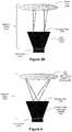
- FIG. 3Aillustrates an example embodiment of detection optics for a ladar receiver, where the imaging detection optics employ a non-imaging light collector.
- FIG. 3Billustrates another example embodiment of detection optics for a ladar receiver, where the afocal detection optics employ a non-imaging light collector.
- FIG. 4illustrates an example embodiment of imaging detection optics for a ladar receiver, where the imaging detection optics employ an imaging light collector.
- FIG. 5Aillustrates an example embodiment of a direct-to-detector embodiment for an imaging ladar receiver.
- FIG. 5Billustrates another example embodiment of a direct-to-detector embodiment for a non imaging ladar receiver.
- FIG. 6Aillustrates an example embodiment for readout circuitry within a ladar receiver that employs a multiplexer for selecting which sensors within a detector array are passed to a signal processing circuit.
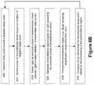
- FIG. 6Billustrates an example embodiment of a ladar receiving method which can be used in connection with the example embodiment of FIG. 6A .
- FIG. 7Adepicts an example embodiment for a signal processing circuit with respect to the readout circuitry of FIG. 6A .
- FIG. 7Bdepicts another example embodiment for a signal processing circuit with respect to the readout circuitry of FIG. 6A .
- FIG. 8depicts an example embodiment of a control circuit for generating the multiplexer control signal.
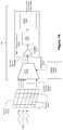
- FIG. 9depicts an example embodiment of a ladar transmitter in combination with a dichroic photodetector.
- FIG. 10Adepicts an example embodiment where the ladar receiver employs correlation as a match filter to estimate a delay between pulse transmission and pulse detection.
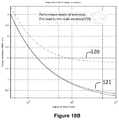
- FIG. 10Bdepicts a performance model for the example embodiment of FIG. 10A .
- FIG. 11Adepicts an example embodiment of a receiver that employs a feedback circuit to improve the SNR of the sensed light signal.
- FIG. 11Bdepicts another example embodiment relating to the feedback circuit design.
- FIG. 12depicts an example process flow for an intelligently-controlled adaptive ladar receiver.
- FIG. 13Adepicts an example ladar receiver embodiment.
- FIG. 13Bdepicts a plot of signal-to-noise ratio (SNR) versus range for daytime use of the FIG. 13A ladar receiver embodiment as well as additional receiver characteristics.
- SNRsignal-to-noise ratio
- FIG. 14Adepicts another example ladar receiver embodiment.
- FIG. 14Bdepicts a plot of SNR versus range for daytime use of the FIG. 14A ladar receiver embodiment as well as additional receiver characteristics.
- FIG. 15depicts an example of motion-enhanced detector array exploitation.
- FIG. 16depicts plots showing motion-enhanced detector array tracking performance.
- FIG. 1Aillustrates an example embodiment of a ladar transmitter/receiver system 100 .
- the system 100includes a ladar transmitter 102 and a ladar receiver 104 , each in communication with system interface and control 106 .
- the ladar transmitter 102is configured to transmit a plurality of ladar pulses 108 toward a plurality of range points 110 (for ease of illustration, a single such range point 108 is shown in FIG. 1A ).
- Ladar receiver 104receives a reflection 112 of this ladar pulse from the range point 110 .
- Ladar receiver 104is configured to receive and process the reflected ladar pulse 112 to support a determination of range point distance and intensity information. Example embodiments for innovative ladar receivers 104 are described below.
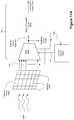
- the ladar transmitter 102can take the form of a ladar transmitter that includes scanning mirrors and uses a range point down selection algorithm to support pre-scan compression (which can be referred herein to as “compressive sensing”), as shown by FIG. 1B .
- Such an embodimentmay also include an environmental sensing system 120 that provides environmental scene data to the ladar transmitter to support the range point down selection.
- Example embodiments of such ladar transmitter designscan be found in U.S. patent application Ser. No. 62/038,065, filed Aug. 15, 2014 and U.S. Pat. App. Pubs.
- the driving waveform that can be used to drive the mirror positions for the X-axis mirrorcan drive the X-axis mirror in a resonant mode
- the driving waveform that can be used to drive the Y-axis mirrorcan drive the Y-axis mirror in a point-to-point mode where the driving waveform varies as function of the shot list.
- FIG. 2illustrates an example block diagram for an example embodiment of a ladar receiver 104 .
- the ladar receivercomprises detection optics 200 that receive light that includes the reflected ladar pulses 112 .
- the detection optics 200are in optical communication with a light sensor 202 , and the light sensor 202 generates signals indicative of the sensed reflected ladar pulses 112 .
- Signal read out circuitry 204reads the signals generated by the sensor 202 to generate signal data that is used for data creation with respect to the range points (e.g., computing range point distance information, range point intensity information, etc.).
- the ladar receiver 104may include additional components not shown by FIG. 2 .
- the light sensor 202may comprise an array of multiple individually addressable light sensors (e.g., an n-element photodetector array).
- the light sensor 202can take the form of a silicon PIN array (e.g., an InGaAs PIN array).
- the light sensor 202can take the form of a silicon avalanche photodiode (APD) array (e.g., an InGaAs APD array).
- the readout circuitry 204can take any of a number of forms (e.g., a read out integrated circuit (ROTC)), and example embodiments for the readout circuitry are described below.
- ROTCread out integrated circuit
- FIG. 3Aillustrates an example embodiment of detection optics 200 for a ladar receiver 104 which employs a non-imaging light collector 302 .
- the non-imaging light collector 302such as a compound parabolic concentrator, does not re-image the image plane at its entrance fixed pupil 304 onto the light sensor 202 with which it is bonded at its exit aperture.
- a lens 300that includes an imaging system for focusing light is in optical communication with the non-imaging light collector 302 .
- the lens 300is positioned and configured such that the lens focuses light (image plane) at the entrance pupil 304 of the light collector 302 even though there is no actual image at the bonded light sensor.
- FIG. 3Billustrates another example embodiment of detection optics 200 which employ a non-imaging light collector 302 .
- an afocal lens group 310is in optical communication with the non-imaging light collector 302 .
- the light collector 302includes an entrance pupil 304 , and it can be bonded with the light sensor 202 at its exit aperture.
- the lens 310is positioned and configured such that the entrance pupil of the afocal lens group is re-imaged at the entrance pupil 304 of the light collector 302 .
- the FIG. 3B embodimentmay omit the afocal lens 310 .
- the light collector 302can take forms such as a fiber taper light collector or a compound parabolic concentrator.
- An example fiber taper light collectoris available from Schott, and an example compound parabolic concentrator is available from Edmunds Optics.
- FIGS. 3A and 3Bprovide various benefits to practitioners. For example, these example embodiments permit the use of relatively small detector arrays for light sensor 202 . As another example, these embodiments can be useful as they provide a practitioner with an opportunity to trade detector acceptance angle for detector size as well as trade SNR for high misalignment tolerance. However, the embodiments of FIGS. 3A and 3B do not produce optimal SNRs relative to other embodiments.
- FIG. 4illustrates an example embodiment of detection optics 200 which employ an imaging light collector 320 .
- the imaging light collector 320re-images the image received at its entrance pupil 304 onto the light sensor 202 .
- a lens 300that includes an imaging system for focusing light is in optical communication with the imaging light collector 320 .
- the lensis positioned and configured such that the lens focuses light (image plane) at the entrance pupil 304 of the light collector 302 , and the light collector 320 images this light onto the bonded light sensor 202 .
- the light collector 320can take the form of a coherent fiber taper light collector.
- An example coherent fiber taper light collectoris available from Schott.
- the example embodiment of FIG. 4also provides various benefits to practitioners. For example, as with the examples of FIGS. 3A and 3B , the example embodiment of FIG. 4 permits the use of relatively small detector arrays for light sensor 202 . This embodiment can also be useful for providing a practitioner with an opportunity to trade detector acceptance angle for detector size as well as trade SNR for high misalignment tolerance. A benefit of the FIG. 4 example embodiment relative to the FIGS. 3A / 3 B example embodiments is that the FIG. 4 example embodiment generally produces higher SNR.
- FIG. 5Aillustrates an example embodiment of “direct to detector” detection optics 200 for a ladar receiver 104 .
- a lens 300that includes an imaging system for focusing light is in optical communication with the light sensor 202 .
- the lens 300is positioned and configured such that the lens focuses light (image plane) directly onto the light sensor 202 .
- FIG. 5Billustrates another example embodiment of “direct to detector” detection optics 200 for a ladar receiver 104 .
- an afocal lens 310is in optical communication with the light sensor 202 .
- the lens 310is positioned and configured such that the lens pupil is re-imaged directly onto the light sensor 202 .
- the inventoralso notes that if desired by a practitioner, the FIG. 5B embodiment may omit the afocal lens 310 .
- FIGS. 5A and 5Bare expected to require a larger detector array for the light sensor 202 (for a given system field of view (FOV) relative to other embodiments), but they are also expected to exhibit very good SNR. As between the embodiments of FIGS. 5A and 5B , the embodiment of FIG. 5A will generally exhibit better SNR than the embodiment of FIG. 5B , but it is expected that the embodiment of FIG. 5B will generally be more tolerant to misalignment (which means the FIG. 5B embodiment would be easier to manufacture).
- FOVsystem field of view
- the detection optics 200can be designed to provide partial imaging of the image plane with respect to the light sensor 202 if desired by a practitioner. While this would result in a somewhat “blurry” image, such blurriness may be suitable for a number of applications and/or conditions involving low fill factor detector arrays.
- FIG. 6Aillustrates an example embodiment for readout circuitry 204 within a ladar receiver that employs a multiplexer 604 for selecting which sensors 602 within a detector array 600 are passed to a signal processing circuit 606 .
- the light sensor 202takes the forms of a detector array 600 comprising a plurality of individually-addressable light sensors 602 .
- Each light sensor 602can be characterized as a pixel of the array 600 , and each light sensor 602 will generate its own sensor signal 610 in response to incident light.
- the array 600can comprise a photodetector with a detection region that comprises a plurality of photodetector pixels.
- FIG. 6Aillustrates an example embodiment for readout circuitry 204 within a ladar receiver that employs a multiplexer 604 for selecting which sensors 602 within a detector array 600 are passed to a signal processing circuit 606 .
- the light sensor 202takes the forms of a detector array 600 comprising a plurality of individually-addressable light
- FIG. 6Aemploys a multiplexer 604 that permits the readout circuitry 204 to isolate the incoming sensor signals 610 that are passed to the signal processing circuit 606 at a given time.
- the embodiment of FIG. 6Aprovides better received SNR, especially against ambient passive light, relative to ladar receiver designs such as those disclosed by U.S. Pat. No. 8,081,301 where no capability is disclosed for selectively isolating sensor readout.
- the signal processing circuit 606can operate on a single incoming sensor signal 610 (or some subset of incoming sensor signals 610 ) at a time.
- the multiplexer 604can be any multiplexer chip or circuit that provides a switching rate sufficiently high to meet the needs of detecting the reflected ladar pulses.
- the multiplexer 604multiplexes photocurrent signals generated by the sensors 602 of the detector array 600 .
- the multiplexer 604multiplexes a resultant voltage signal generated by the sensors 602 of the detector array 600 .
- a ladar receiverthat includes the readout circuitry 204 of FIG.
- 6Ais paired with a scanning ladar transmitter that employs pre-scan compressive sensing (such as the example embodiments employing range point down selection that are described in the above-referenced and incorporated patent applications), the selective targeting of range points provided by the ladar transmitter pairs well with the selective readout provided by the multiplexer 604 so that the receiver can isolate detector readout to pixels of interest in an effort to improve SNR.
- pre-scan compressive sensingsuch as the example embodiments employing range point down selection that are described in the above-referenced and incorporated patent applications
- a control circuit 608can be configured to generate a control signal 612 that governs which of the incoming sensor signals 610 are passed to signal processing circuit 606 .
- the control signal 612can cause the multiplexer to selectively connect to individual light sensors 602 in a pattern that follows the transmitter's shot list (examples of the shot list that may be employed by such a transmitter are described in the above-referenced and incorporated patent applications).
- the control signal 612can select sensors 602 within array 600 in a pattern that follows the targeting of range points via the shot list.
- FIG. 8shows an example embodiment for control circuit 608 .
- the control circuit 608receives the shot list 800 as an input. This shot list is an ordering listing of the pixels within a frame that are to be targeted as range points by the ladar transmitter.
- the control circuitselects a first of the range points/target pixels on the shot list.
- the control circuitmaps the selected range point to a sensor/pixel (or a composite pixel/superpixel) of the detector array 600 .
- control circuitthen generates a control signal 612 that is effective to cause the multiplexer to readout the mapped sensor/pixel (or composite pixel/superpixel) of the detector array 600 .
- control circuitprogresses to the next range point/target pixel on the shot list and returns to operation 802 . If necessary, the control circuit 608 can include timing gates to account for round trip time with respect to the ladar pulses targeting each pixel.
- control signal 612can be effective to select a single sensor 602 at a time or it can be effective to select multiple sensors 602 at a time in which case the multiplexer 604 would select a subset of the incoming sensor signals 610 for further processing by the signal processing circuit 606 .
- Such multiple sensorscan be referred to as composite pixels (or superpixels).
- the array 600may be divided into an J ⁇ K grid of composite pixels, where each composite pixel is comprised of X individual sensors 602 .
- Summer circuitscan be positioned between the detector array 600 and the multiplexer 604 , where each summer circuit corresponds to a single composite pixel and is configured to sum the readouts (sensor signals 610 ) from the pixels that make up that corresponding composite pixel.
- FIG. 6Bdepicts an example ladar receiving method corresponding to the example embodiment of FIG. 6A .
- a ladar pulseis transmitted toward a targeted range point.
- a location of this targeted range point in a scan area of the field of viewcan be known by the ladar transmitter. This location can be passed from the ladar transmitter to the ladar receiver or determined by the ladar receiver itself, as explained below.
- a subset of pixels in the detector array 600are selected based on the location of the targeted range point. As indicated in connection with FIG. 8 , a mapping relationship can be made between pixels of the detector array 600 and locations in the scan area such that if pixel x1,y1 in the scan area is targeted, this can be translated to pixel j1,k1 in the detector array 600 .
- the subsetmay include only a single pixel of the detector array 600 , but in many cases the subset will comprise a plurality of pixels (e.g., the specific pixel that the targeted range point maps to plus some number of pixels that surround that specific pixel). Such surrounding pixels can be expected to also receive energy from the range point ladar pulse reflection, albeit where this energy is expected to be lower than the specific pixel.
- the selected subset of pixels in the detector array 600senses incident light, which is expected to include the reflection/return of the ladar pulse transmitted at step 620 .
- Each pixel included in the selected subsetwill thus produce a signal as a function of the incident sensed light (step 626 ). If multiple pixels are included in the selected subset, these produced pixel-specific signals can be combined into an aggregated signal that is a function of the incident sensed light on all of the pixels of the selected subset.
- the detector pixels that are not included in the selected subsetcan also produce an output signal indicative of the light sensed by such pixels, but the system will not use these signals at steps 626 - 630 .
- the systemcan be configured to “zero out” the pixels in the selected subset prior to read out at steps 624 and 626 eliminate the effects of any stray/pre-existing light that may already be present on such pixels.
- the photodetector signal generated at step 626is processed.
- the photodetector signalcan be amplified and digitized to enable further processing operations geared toward resolving range and intensity information based on the reflected ladar pulse. Examples of such processing operations are discussed further below.
- range information for the targeted range pointis computed based on the processing of the photodetector signal at step 628 .
- This range computationcan rely on any of a number of techniques.
- the computed range informationcan be any data indicative of a distance between the ladar system 100 and the targeted range point 110 .
- the computed range informationcan be an estimation of the time of transit for the ladar pulse 108 from the transmitter 102 to the targeted range point 110 and for the reflected ladar pulse 112 from the targeted range point 110 back to the receiver 104 .
- Such transit time informationis indicative of the distance between the ladar system 100 and the targeted range point 110 .
- the range computationcan rely on a measurement of a time delay between when the ladar pulse was transmitted and when the reflected ladar pulse was detected in the signal processed at step 628 . Examples of techniques for supporting such range computations are discussed below.
- FIG. 6Bdescribes an adaptive ladar receiving method where the active sensing region of the detector array 600 will change based on where the ladar pulses are targeted by the ladar transmitter. In doing so, it is believed that significant reductions in noise and improvements in range resolution will be achieved. Further still, as explained in greater detail below, the subset of detector pixels can be adaptively selected based on information derived from the sensed light to further improve performance.
- the signal processing circuit 606can be configured to amplify the selected sensor signal(s) passed by the multiplexer 604 and convert the amplified signal into processed signal data indicative of range information and/or intensity for the ladar range points.
- Example embodiments for the signal processing circuit 606are shown by FIGS. 7A and 7B .
- the signal processing circuit 606comprises an amplifier 700 that amplifies the selected sensor signal(s), an analog-to-digital converter (ADC) 702 that converts the amplified signal into a plurality of digital samples, and a field programmable gate array (FPGA) that is configured to perform a number of processing operations on the digital samples to generate the processed signal data.
- ADCanalog-to-digital converter
- FPGAfield programmable gate array
- the amplifier 700can take the form of a low noise amplifier such as a low noise RF amplifier or a low noise operational amplifier.
- the ADC 702can take the form of an N-channel ADC.
- the FPGA 704includes hardware logic that is configured to process the digital samples and ultimately return information about range and/or intensity with respect to the range points based on the reflected ladar pulses.
- the FPGA 704can be configured to perform peak detection on the digital samples produced by the ADC 702 .
- peak detectioncan be effective to compute range information within +/ ⁇ 10 cm.
- the FPGA 704can also be configured to perform interpolation on the digital samples where the samples a curve fit onto a polynomial to support an interpolation that more precisely identifies where the detected peaks fit on the curve.
- such interpolationcan be effective to compute range information within +/ ⁇ 5 mm.
- the receiverWhen a receiver which employs a signal processing circuit such as that shown by FIG. 7A is paired with a ladar transmitter that employs compressive sensing as described in the above-referenced and incorporated patent applications, the receiver will have more time to perform signal processing on detected pulses because the ladar transmitter would put fewer ladar pulses in the air per frame than would conventional transmitters, which reduces the processing burden placed on the signal processing circuit.
- the FPGA 704can be designed to leverage the parallel hardware logic resources of the FPGA such that different parts of the detected signal are processed by different hardware logic resources of the FPGA at the same time, thereby further reducing the time needed to compute accurate range and/or intensity information for each range point.
- the signal processing circuit of FIG. 7Ais capable of working with incoming signals that exhibit a low SNR due to the signal processing that the FPGA can bring to bear on the signal data in order to maximize detection.
- the signal processing circuit 606comprises the amplifier 700 that amplifies the selected sensor signal(s) and a time-to-digital converter (TDC) 710 that converts the amplified signal into a plurality of digital samples that represent the sensed light (including reflected ladar pulses).
- the TDCcan use a peak and hold circuit to detect when a peak in the detected signal arrives and also use a ramp circuit as a timer in conjunction with the peak and hold circuit.
- the output of the TDC 710can then be a series of bits that expresses timing between peaks which can be used to define range information for the range points.
- the signal processing circuit of FIG. 7Bgenerally requires that the incoming signals exhibit a higher SNR than the embodiment of FIG. 7A , but the signal processing circuit of FIG. 7B is capable of providing high resolution on the range (e.g., picosecond resolution), and benefits from being less expensive to implement than the FIG. 7A embodiment.
- the signal processing circuit of FIG. 7Bis capable of providing high resolution on the range (e.g., picosecond resolution), and benefits from being less expensive to implement than the FIG. 7A embodiment.
- FIG. 9discloses an example embodiment where the ladar transmitter 102 and a photodetector 900 are used to provide the ladar receiver 104 with tracking information regarding where the ladar transmitter (via its scanning mirrors) is targeted.
- photodetector 900is positioned optically downstream from the scanning mirrors (e.g., at the output from the ladar transmitter 102 ), where this photodetector 900 operates as (1) an effectively transparent window for incident light that exhibits a frequency within a range that encompasses the frequencies that will be exhibited by the ladar pulses 108 (where this frequency range can be referred to as a transparency frequency range), and (2) a photodetector for incident light that exhibits a frequency that is not within the transparency frequency range.
- the doped/intrinsic layer and the substrate of the photodetectorcan be chosen so that the ladar pulses 108 fall within the transparency frequency range while light at another frequency is absorbed and detected.
- the region of the photodetector that exhibits this dual property of transmissiveness versus absorption/detection based on incident light frequencycan be housed in an optically transparent/transmissive casing.
- the electronic circuitry of photodetector 900 that supports the photodetection operationscan be housed in another region of the photodetector 900 that need not be transparent/transmissive.
- Such a photodetector 900can be referred to as a dichroic photodetector.
- the ladar transmitter 102 of FIG. 9is equipped with a second light source (e.g., a second bore-sighted light source) that outputs light 902 at a frequency which will be absorbed by the photodetector 900 and converted into a photodetector output signal 904 (e.g., photocurrent q).
- Light 902can be laser light, LED light, or any other light suitable for precise localized detection by the photodetector 900 .
- the ladar transmitter 102can align light 902 with ladar pulse 108 so that the scanning mirrors will direct light 902 in the same manner as ladar pulse 108 .
- the photodetector's output signal 904will be indicative of the x,y position of where light 902 strikes the photodetector 900 .
- signal 904will also be indicative of where ladar pulse 108 struck (and passed through) the photodetector 900 . Accordingly, signal 904 serves as a tracking signal that tracks where the ladar transmitter is targeted as the transmitter's mirrors scan. With knowledge of when each ladar pulse was fired by transmitter 102 , tracking signal 904 can thus be used to determine where the ladar transmitter was aiming when a ladar pulse 108 is fired toward a range point 110 . We discuss below how timing knowledge about this firing can be achieved. Tracking signal 904 can then be processed by a control circuit in the ladar receiver 104 or other intelligence within the system to track where ladar transmitter 102 was targeted when the ladar pulses 108 were fired.
- the systemBy knowing precisely where the transmitter is targeted, the system is able to get improved position location of the data that is collected by the receiver.
- the inventorsanticipate that the system can achieve 1 mrad or better beam pointing precision for a beam divergence of around 10 mrad. This allows for subsequent processing to obtain position information on the range point return well in excess of the raw optical diffraction limit.
- FIG. 10Adiscloses an example embodiment where an optical path distinct from the path taken by ladar pulse 108 from the transmitter 102 toward a range point and back to the receiver 104 via ladar pulse reflection 112 is provided between the ladar transmitter 102 and ladar receiver 104 , through which reference light 1000 is communicated from transmitter 102 to receiver 104 , in order to improve range accuracy. Furthermore, this distinct optical path is sufficient to ensure that the photodetector 600 receives a clean copy of the reference light 1000 .
- This distinct optical pathcan be a direct optical path from the transmitter 102 to the receiver's photodetector 600 .
- the receiver 104can include a pinhole or the like that passes light from the transmitter 102 to the photodetector 600 .
- this direct optical pathcan be readily assured because the laser transmit power is considerably stronger than the received laser return signal. For instance, at 1 km, with a 1 cm receive pupil, and 10% reflectivity, the reflected light sensed by the receiver will be over 1 billion times smaller than the light at the transmitter output.
- a fiber optic feedcan be split from the main fiber laser source and provide the direct optical path used to guide the reference light 1000 , undistorted, onto the photodetector.
- the reference light 1000spawned at the exact time and exact location as the ladar pulse 108 fired into the environment, can be the same pulse as ladar pulse 108 to facilitate time delay measurements for use in range determinations.
- the reference light 1000comprises photons with the same pulse shape as those sent into the field.
- the reference light pulseis clean with no noise and no spreading.
- the photodetector 600receives the reference pulse 1000 via the distinct optical path and then later the reflected ladar pulse 112 .
- the signal sensed by the photodetector 600can then be digitized by an ADC 1002 and separated into two channels.
- a delay circuit/operator 1004delays the digitized signal 1006 to produce a delayed signal 1008 .
- the delayed signal 1008is then compared with the digitized signal 1006 via a correlation operation 1010 .
- This correlation operationcan be the multiplication of each term 1006 , 1008 summed across a time interval equal to or exceeding the (known) pulse length.
- the correlation output 1012will reach a maximum value when the two signals are aligned with each other.
- This alignmentwill indicate the delay between reference pulse 1000 and reflected pulse 112 , and this delay can be used for high resolution range determination. For example, suppose, the reference light signal 1000 arrives 3 digital samples sooner than the reflected ladar pulse 112 . Assume these two signals are identical (no pulse spreading in the reflection), and equal, within a scale factor, ⁇ 1,2,1 ⁇ , i.e. the transmit pulse lasts three samples. Then for a delay of zero in 1004 , summing twice the pulse length, the output is ⁇ 1,2,1,0,0,0 ⁇ times ⁇ 0,0,0,1,2,1 ⁇ .
- the transmittercan be expected to be capable of firing 150,000 pulses every second, it is expected that there will be sufficient timing space for ensuring that the receiver gets a clean copy of the reference light 1000 with no light coming back from the ladar pulse reflection 112 .
- the delay and correlation circuit shown by FIG. 10Acan also be referred to as a matched filter.
- the matched filtercan be implemented in an FPGA or other processor that forms part of signal processing circuit 606 .
- FIG. 10Ashows a single photodetector 600 and ADC 1002 in the receiver
- separate photodetectorscan be used to detect the return pulse 112 and the reference pulse 1000 .
- separate ADCscould be used to digitize the outputs from these photodetectors.
- interpolation of the sampled return pulse 112can be performed as well using pulse 1000 as a reference. After peak finding, conducted using the process described above, the system can first interpolate the reference light signal.
- Making reference pulse 1000 the same as ladar pulse 108 in terms of shapecontributes to the improved accuracy in range detection because this arrangement is able to account for the variation in pulse 108 from shot to shot.
- rangeis improved from the shape, and reflectivity measurement is improved by intensity, using pulse energy calibration (which is a technique that simply measures energy on transmit).
- the range caseis revealed in modeling results shown by FIG. 10B .
- the vertical axis of FIG. 10Bis range accuracy, measured as ⁇ x cm, i.e. x standard deviations measured in cm, and the horizontal axis of FIG. 10B is the SNR.
- This modelis applied to a 1 ns full width half maximum Gaussian pulse.
- the bottom line plotted in FIG. 10Bis the ideal case.
- the nearby solid line 121is the plot for an ADC with 1 picosecond of timing jitter, which is a jitter level readily available commercially for 2 GHz ADCs.
- jitteris not a limiting factor in achieving sub-cm resolution.
- the lower curve (no jitter) and upper curve (jitter)differ by only a millimeter at very high (and usually unachievable) SNR [ ⁇ 1000].
- pulse variationis a significant limitation. This is seen by 120 , which is the performance available with 5% pulse-to-pulse shape variation, a common limit in commercial nanosecond-pulsed ladar systems.
- the difference between 120 and 121is the improvement achieved by example embodiments of the disclosed FIG. 10A technique, for both peak finding and interpolation as a function of SNR.
- the correlation and interpolationcan be implemented after a prior threshold is crossed by the data arriving from the reflected lidar pulse. This greatly reduces complexity, at no performance cost.
- the intent of correlation and interpolationis to improve ranging—not detection itself, so delaying these operations and applying them only around neighborhoods of detected range returns streamlines computations without eroding performance. Typically only 3 samples are taken of the reference light pulse since it is so short. Interpolating this 20-fold using cubic models requires only about 200 operations, and is done once per shot, with nominally 100,000 shots.
- the total burden pre matching filter and interpolation against the ladar receive pulseis then 20 Mflops. If we select the largest, first and last pulse for processing, this rises to less than 100 Mflop, compared to teraflops available in modern commercial devices.
- FIG. 11Adiscloses an example embodiment of a receiver design that employs a feedback circuit 1100 to improve the SNR of the signals sensed by the active sensors/pixels 602 .
- the feedback circuit 1100can be configured as a matching network, in resonance with the received ladar pulse return 112 (where the ladar pulse 108 and return pulse 112 can exhibit a Gaussian pulse shape in an example embodiment), thereby enhancing the signal and retarding the noise.
- a photodetector performanceis a function of pitch (area of each element) and bandwidth. Passive imagers lack prior knowledge of incident temporal signal structure and have thus no ability to tune performance.
- the transmitted ladar pulse 108is known, as it is arrival time within the designated range swath. This knowledge can facilitate a matching network feedback loop that filters the detector current, increases signal strength, and filters receiver noise. A feedback gain provided by the feedback circuit can be controlled via a control signal 1102 from control circuit. Furthermore, it should be understood that the control circuit 608 can also be in communication with the signal processing circuit 606 in order to gain more information about operating status for the receiver.
- the matching; network of the feedback circuit 1100may be embedded into the In—GaAs substrate of detector 600 to minimize RF coupling noise and cross channel impedance noise.
- the cost of adding matching networks onto the detector chipis minimal. Further, this matching allows us to obtain better dark current, ambient light, and Johnson noise suppression than is ordinarily available. This further reduces required laser power, which, when combined with a 1.5 um wavelength for ladar pulses 108 leads, to a very eye safe solution.
- the matching networkcan be comprised of more complex matching networks with multiple poles, amplifiers, and stages. However, a single pole already provides significant benefits. Note that the input to the signal processing circuit 606 can be Gaussian, regardless of the complexity of the multiplexer, the feedback, or the size variability of the pixels, due to the convolutional and multiplicative invariance of this kernel.
- FIG. 11Bshows an example that expands on how the feedback circuit 1100 can be designed.
- the matching networkinvolves one or more amplifiers 1102 , in a controlled feedback loop 1104 with a gain controller furnished by the control circuit 608 .
- the matching networkcan be present on all the input lines to the mux 604 , and FIG. 11B shows just show a single such network, within the dotted box 1120 , for ease of illustration.
- the feedback gainis generally chosen to output maximal SNR using differential equations to model the input/output relationships of the feedback circuit.
- the control loopcan be designed to monitor the mux output and adjust the amplifiers 1102 to account from drift due to age, thermal effects, and possible fluctuations in ambient light.
- Embodimentsare also disclosed herein which employ two or more digital channels to build a filter (e.g. a Weiner filter or least mean squares filter) to reject interference from strong scatterers, other ladar pulses, or even in-band sunlight, headlights or other contaminants.
- a filtere.g. a Weiner filter or least mean squares filter
- the feedback circuitcan be reset at each shot to avoid any saturation from contamination in the output from shot to shot.
- the ladar pulse 108 and its return pulse 112can exhibit a Gaussian pulse shape.
- the Fourier representation of the pulseis also Gaussian, and the gain selection by, the control circuit 608 is tractable, ensuring rapid and precise adaptation.
- FIG. 11BAnother innovative aspect of the design shown by FIG. 11B is the use of hexagonally shaped pixels for a plurality of the sensors 602 within the photodetector array 600 .
- the shaded area 1130indicates the selected subset of pixels chosen to pass to the signal processing circuit 606 at a given time.
- the receivercan grow or shrink the size of the shaded area 1130 , either by adding or subtracting pixels/sensors 602 .
- the hexagonal shape of pixels/sensors 602provides a favorable shape for fault tolerance since each hexagon has 6 neighbors.
- the pixels/sensors 602 of the photodetector array 600can exhibit different sizes and/or shapes if desired by a practitioner. For example, some of the pixels/sensors can be smaller in size (see 1132 for example) while other pixels/sensors can be larger in size (see 1134 ). Furthermore, some pixels/sensors can be hexagonal, while other pixels/sensors can exhibit different shapes.
- FIG. 12depicts an example process flow for implementing adaptive control techniques for controlling how the receiver adapts the active region of the photodetector array 600 .
- a list of pixels eligible for inclusion in subset 1130is defined.
- This listcan be any data structure 1202 that includes data indicative of which pixels 602 are eligible to be selected for inclusion in the subset 1130 .
- Such a data structuremay be maintained in memory that is accessible to a processor that implements the FIG. 12 process flow. While the example of FIG. 12 shows a list 1202 that identifies eligible pixels 602 , it should be understood that data structure 1202 could also serve as an effective blacklist that identifies pixels that are ineligible for inclusion in subset 1130 .
- a circuite.g., signal processing circuit 606 and/or control circuit 608
- a processing logice.g., an FPGA
- This derived informationmay include information such as whether any saturation conditions exist, whether any pixels are malfunctioning, whether there are any areas of high noise in the field of view, etc. Examples of derived information that can be useful for adaptive control are discussed below.
- the oversaturation conditionscan be attributed to specific pixels (e.g., pixels that are blinded by intense incident light) and/or can be attributed to the aggregated signal resulting from the combination of pixel readings by the pixels included in subset 1130 (where the aggregation of pixel outputs oversaturates the linear operating range of the processing circuitry).
- the list of eligible pixels 1202is adjusted based on the information derived at step 1204 . For example, if a given pixel is found to be malfunctioning as a result of step 1204 , this pixel can be removed from list 1202 at step 1206 . Similarly, any oversaturated pixels can be removed from the list 1202 and/or any pixels corresponding to overly noisy areas of the field of view (e.g., regions where the noise exceeds a threshold) can be removed from list 1202 at step 1206 .
- any oversaturated pixelscan be removed from the list 1202 and/or any pixels corresponding to overly noisy areas of the field of view (e.g., regions where the noise exceeds a threshold) can be removed from list 1202 at step 1206 .
- the systemselects pixels from the list 1202 of eligible pixels based on the targeted range point. This can be performed as described in connection with step 804 of FIG. 8 , but where list 1202 defines the pool of pixels eligible to be selected as a function of the location of the targeted range point in the scan area/field of view.
- list 1202defines the pool of pixels eligible to be selected as a function of the location of the targeted range point in the scan area/field of view.
- step 12may operate to define subset 1130 such that the upper left neighboring pixel of pixel 1140 is not included in subset 1130 if the upper left neighboring pixel was removed from list 1202 at step 1206 (e.g., due to a detected malfunction or the like).
- step 1208may also operate to use the information derived at step 1204 to affect which eligible pixels are included in the subset. For example, additional pixels might be added to the subset 1130 to increase the size of the active sensor region based on the derived information. Similarly, the size of the active sensor region might be shrunk by using fewer pixels in the subset 1130 based on the derived information. Thus, it should also be understood that the size of the active region defined by the selected subset 1130 may fluctuate from shot to shot based on information derived at step 1204 .
- the process flow of FIG. 12defines a technique for intelligently and adaptively controlling which pixels in array 600 are used for sensing ladar pulse returns.
- the FIG. 12 process flowcan also be used to impact transmitter operation.
- the list of eligible pixels(or a list of ineligible pixels) can be provided to the ladar transmitter for use by the ladar transmitter to adjust the timing/order of shots on its shot lists (e.g., avoiding shots that will likely be corrupted by noise on receive).
- the ladar transmittercan reduce the power used by the ladar pulses 108 to reduce the likelihood of oversaturation on the receive side.
- the ladar transmittercan repeat the corrupted shot by reducing the power for ladar pulse 108 and re-transmitting the reduced power pulse.
- control techniquesthat can be employed by the ladar system. While each control technique will be discussed individually and should be understood as being capable of implementation on its own, it should also be understood that multiples of these control techniques can be aggregated together to further improve performance for the adaptive receiver. As such, it should be understood that in many instances aggregated combinations of these control techniques will be synergistic and reinforcing. In other cases, tradeoffs may exist that are to be resolved by a practitioner based on desired operating characteristics for the receiver.
- a dead pixeltypically leads to irrecoverable loss.
- a malfunctioning pixel 602has minimal effect.
- a lensthat maps the far field scene to a 7-pixel super/composite pixel 1130 (a specified pixel 1140 and its neighbors). Losing one pixel leads to a loss of 1/7 of the net photon energy. If the detector array is shot noise-limited, then we have only a 7% loss in energy, versus 100% loss for a full imaging array.
- An example control flow for a fault tolerant adaptive maskis shown below as applied to an embodiment where the ladar transmitter employs compressive sensing.
- a maskcan be used by the control circuit 608 to define which pixels 602 are included in the selected subset of active sensors and which are not so included.
- the maskcan be a data signal where each bit position corresponds to a different pixel in the array 600 . For bit positions having a value of “1”, the corresponding pixel 602 will be included in the selected subset, while for bit positions having a value of “0”, the corresponding pixel 602 would not be included in the selected subset.
- a pixel 602 that is unable to detect lightshould not be included in the selected subset because such a dead pixel would add noise but no signal to the aggregated sensed signal corresponding to the composite pixel defined by the selected subset. Furthermore, it should be understood that malfunctioning pixels are not limited to only dead pixels.
- a pixel 602 that produces an output signal regardless of whether incident light is receivedshould also be omitted from the selected subset.
- a white pixelmay be even worse than a dark pixel because the stuck charge produced by the white pixel can lead to a constant bright reading which adds glare to all returns in the composite pixel.
- An example control process flowis described below for generating an adaptive fault tolerant mask that can adjust which pixels 602 are included in the selected subset based on which pixels 602 are detected as malfunctioning:
- Fault tolerance in this fashioncan be a useful step in improving safety, since without mitigation single defects can render an entire FOV inoperative.
- the adaptive control over which subsets of pixels are activated at a given timecan also be used to adjust the dynamic range of the system. Based on range knowledge, the signal produced by a composite pixel will have predictable intensity.
- a maskcan be constructed that reduces (or increases) the dynamic range of the return at the ADC pre-filter and/or the ADC itself by adjusting the size of the composite pixel defined by the pixels 602 included in the selected subset. For example, if the typical composite pixel is 7 pixels (see 1130 in FIG. 11B ), adjusting the subset such that it drops from 7 pixels to a single pixel reduces the energy by 7 times (or roughly three bits). Photodetectors measure energy of light, not amplitude of light.
- the ADCs dynamic rangeis the square of that for conventional communications and radar circuits which measure amplitude.
- properly controlling dynamic rangeis a technical challenge for laser systems. For example, a ladar system tuned to operate over 10-500 m will, for a fixed reflectivity and laser power, undergo a signal return dynamic range change by 2500. If a nearby object saturates the receiver, a farther out target will be lost. Therefore, an example embodiment can include an analysis of prior shot range returns in the instantaneous field of view to assess the need to excise any pixels from the selected subset in the mux circuit.
- the incoming light that is incident on the photodetector array 600might include not only a ladar pulse return 112 from the vehicle that carries the subject ladar system but also a ladar pulse or ladar pulse return from a different ladar system carried by a different vehicle (an interfering “off-car” pulse).
- Adaptive isolation of such interfering pulsescan be achieved by creating a sub-mask of selected pixels 602 by excising pixels associated with strong interfering pulses from other ladar systems.
- pulse encodingcan be employed to facilitate the resolution as to which ladar pulses are “own” pulses and which are “off” pulses (e.g., “off-car” pulses). For example, consider that such encoding is used to detect that pixel 1134 contains energy from an interfering ladar pulse. We would then scan through the pixels of the array (with the cluster 1130 for example) to see which are receiving interference. In one embodiment, this would involve removing the “own” lidar pulse using encoding, measuring the resulting signal after subtraction, and comparing to a predetermined threshold. In another embodiment, the system would simply analyze the MUX output, subtract off the “own” pulse encoding signal and compare the remainder to a threshold.
- control circuit 608can remove this pixel 1134 from a list of eligible pixels for inclusion in a selected subset while the interfering pulse is registered by that pixel 1132 .
- the systemmight also remove pixels based on headlight source localization from passive video dining night time operations (the operational conservative assumption here being that every vehicle with a headlight has a ladar transmitter). Furthermore, since pulse collision detection can be used to reveal off-car pulses, this information can be used to treat any selected off car laser source as a desired signal, subtract off the rest (including own-car ladar pulses) and scan through pixels of the array to find where this interference is largest. In doing so we will have identified the source of each interfering ladar source, which can then be subsequently removed.
- Another potential source of noise in the light sensed by the receiveris when a ladar pulse strikes an object that exhibits a strong scattering effect (e.g., a strongly slanted and reflective object as opposed to a more ideally-oriented object that is perpendicular to the angle of impact by the ladar pulse 108 ).
- Targets exhibiting multiple returnshave information bearing content.
- this contentcan be lost due to excessive dynamic range, because the largest return saturates driving the receiver into nonlinear modes, and/or driving the weaker returns below the sensor detection floor.
- the direct returnis the largest, while successive returns are weakened by the ground bounce dispersion, but this is not the case when reflectivity is higher in bounce returns.
- the maskit is desirable to adjust the mask so that the near-in range samples receive a higher pupil (dilation) (e.g., where the selected subset defines a larger area of the array 600 ), while the farther out range samples undergo pupil contraction (e.g., where the selected subset defines a smaller area of the array 600 ).
- a higher pupile.g., where the selected subset defines a larger area of the array 600
- the farther out range samplesundergo pupil contraction
- the selected subsetdefines a smaller area of the array 600.
- the use of an adaptive maskwill allow for the removal of this scatterer by over-resolving the spot beam (e.g., more than one pixel covered by the shot return beam) on receive, thereby reducing saturation or scatterer leakage into the target cell.
- the dynamic rangecan be further reduced by deliberately timing the laser pulse by the transmitter so that the laser peak intensity does not fall on the target but instead falls away from near-to-the-target interference, thereby increasing the signal to clutter ratio.
- Thisallows for near-in interference suppression above and beyond that obtained by other means.
- the upper sensor cell 1132contains a very strong target and the lower nearby sensor cell also labeled 1132 contains a target.
- the maskis tuned so that the beam peak of the receive beam is away from a noise source (e.g., incoming traffic) we can reduce strong returns from nearby vehicles while imaging at distance, a milliradian in some cases suffices to reduce strong scatterers by 95% while attenuating the target object by only a few percent.
- selective sensingcan be used to determine the mask parameters, although compressive sensing, or fixed roadmap-based solutions may also be chosen.
- An example hereis lane structure, since opposing lane traffic yields the largest interference volume. The system could thereby adjust the shots, or the ordering of shots to avoid noisy areas while retaining the desired object information.
- the center pixelwill have the most energy. Therefore it will saturate before any of the others. Therefore one approach for reducing saturation risk is to simply remove the center pixel from the mask 1130 if evidence of, or concern regarding, saturation is present.
- One benefit of the advanced receiver disclosed hereinis that only a single data channel is needed, as opposed to M where M is the pixel count. However, one can still retain a low cost and swap system by adding a second channel.
- This second channellike the first channel, can either be a full up analog to digital converter (see FIG. 7A ) or a time of flight digitizer (see FIG. 7B ).
- Either embodimentallows for coherent combining (in intensity) to optimally suppress the interference using filtering (such as Weiner Filtering or Least Means Squared (LMS) Filtering).
- filteringsuch as Weiner Filtering or Least Means Squared (LMS) Filtering
- FIGS. 6A-12can be particularly useful when paired with detection optics such as those shown by FIGS. 4 and 5A , where the sensed light is imaged onto the detector array 600 .
- the image pulseis not imaged onto the detector array 600 (e.g., the embodiments of FIGS. 3A, 3B, and 5B (or embodiments where the image is “blurry” due to partial imaging)
- a practitionermay choose to omit the multiplexer 604 as there is less of a need to isolate the detected signal to specific pixels.
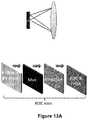
- FIG. 13Adepicts an example ladar receiver embodiment where “direct to detector” detection optics such as that shown by FIG. 5A are employed and where the readout circuitry of FIG. 7A is employed.
- the receiveremploys a low number N-element detector array such as a silicon or InGaAs PIN/APD array.
- the receivermay exhibit a 2 cm input aperture, a 14 mm focal length, and it may work in conjunction with an approximately 0.2-5.0 nanosecond laser pulse of around 4 microJoules per pulse.
- FIG. 13Bdepicts a plot of SNR versus range for daytime use of the FIG. 13A ladar receiver embodiment.
- FIG. 13Balso shows additional receiver characteristics for this embodiment.
- the range at reflectivity of 80% (metal)is over 600 m.
- the max range envelopeis between around 150 m and around 600 m depending on real life target reflectivities and topography/shape.
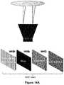
- FIG. 14Adepicts an example ladar receiver embodiment where detection optics such as that shown by FIG. 3B are employed and where the readout circuitry of FIG. 7A is employed.
- the receiveremploys a low number N-element detector array such as a silicon or InGaAs PIN/APD array.
- the receiver of FIG. 14Amay exhibit a 2 cm input aperture, employ an afocal non-imaging lens, and it may work in conjunction with an approximately 0.2-5.0 nanosecond laser pulse of around 4 microJoules per pulse.
- FIG. 14Adepicts an example ladar receiver embodiment where detection optics such as that shown by FIG. 3B are employed and where the readout circuitry of FIG. 7A is employed.
- the receiveremploys
- FIG. 14Bdepicts a plot of SNR versus range for daytime use of the FIG. 14A ladar receiver embodiment.
- FIG. 14Balso shows additional receiver characteristics for this embodiment.
- the range at reflectivity of 80% (metal)is around 180 m.
- the max range envelopeis between around 40 m and around 180 m depending on real life target reflectivities and topography/shape.
- the stochastic modulation of the two way (known) beam patternembeds position information on the point cloud(s) obtained.
- FIG. 15where we show the detector output for a given azimuth and elevation pixel, with each row being the range returns from a single shot.
- the solid white curve 1502shows how a specified, fixed, ground reference point varies vertically due to vehicle motion. Note that the motion can lead to a non-linear contour. This is due to the fact that, even for fixed velocity, the ground plane projection does not, at near range, present a planar projection.
- the relative motion exploitation that we proposeis to integrate the detector array outputs, either binary or intensity, along these contours to recreate the ground plane map.
- Such integrationis necessitated in practice by the fact that the pulse spreads and thus each shot will present weak returns.
- the asphalttends to have rather low reflectivity, on the order of 20%, further complicating range information extraction.
- the white rectangular region 1502show the migration in shots for a vehicle presenting relative motion with respect to the laser source vehicle. To simplify the plot, we show the case where differential inter-velocity [closing speed] is constant.
- the width of the rectangle 1502presents the uncertainty in this differential.
- the scaleshows this width is much larger than the width for ground mapping described above.
Landscapes
- Engineering & Computer Science (AREA)
- Physics & Mathematics (AREA)
- Computer Networks & Wireless Communication (AREA)
- General Physics & Mathematics (AREA)
- Radar, Positioning & Navigation (AREA)
- Remote Sensing (AREA)
- Electromagnetism (AREA)
- Optical Radar Systems And Details Thereof (AREA)
- Measurement Of Optical Distance (AREA)
- Measurement Of Velocity Or Position Using Acoustic Or Ultrasonic Waves (AREA)
- Radar Systems Or Details Thereof (AREA)
Abstract
Description
- 1: select a background pixel status probe shot schedule repetition rate (e.g., nominally one per hour)
- 2: Decompose: In the past previous time block T identify S, the set of pixels not yet selected for illumination. Decompose into S1, S2, the former being addressable (strong return in scene) while the latter is defined to be non-addressable (ex: above horizon). Note that S1, S2 are time varying.
- 3: Shot list: Enter S1, S2 into the shot list.
- 4: construct a mask to deselect faulty tiles identified from analysis of returns from 1-3 (either no return or anomalous gain), The super-pixel size can be set based on the lens and tile pitch but can nominally be 7.
- 5: recurse 1-4.
- 6: average: In the above, as necessary, apply running averages on pixel probe, and include adaptive metrology.
- 1, Inspect range return from a pulse return of interest, obtained from either selective or compressive sensing.
- 2. Identify any saturation artifacts, as evidenced by ADC reports at the MSB (most significant bit) for several range samples.
- 3. Map the saturated range sample to a precise azimuth and elevation of origin. This may involve exploring adjacent cells to determine origin from context, particularly at longer range as beam divergence is more pronounced.
- 4. Modify the mask to reduce saturation by blocking the pixels that present a larger gain in the origin identified in 3.
- 5. Modify the mask further by selecting only smaller area pixels as required.
Claims (30)
Priority Applications (2)
| Application Number | Priority Date | Filing Date | Title |
|---|---|---|---|
| US17/024,014US11175386B2 (en) | 2016-02-18 | 2020-09-17 | Ladar system with adaptive receiver |
| US17/523,509US20220066000A1 (en) | 2016-02-18 | 2021-11-10 | Ladar System with Adaptive Receiver |
Applications Claiming Priority (3)
| Application Number | Priority Date | Filing Date | Title |
|---|---|---|---|
| US201662297112P | 2016-02-18 | 2016-02-18 | |
| US15/430,235US10782393B2 (en) | 2016-02-18 | 2017-02-10 | Ladar receiver range measurement using distinct optical path for reference light |
| US17/024,014US11175386B2 (en) | 2016-02-18 | 2020-09-17 | Ladar system with adaptive receiver |
Related Parent Applications (1)
| Application Number | Title | Priority Date | Filing Date |
|---|---|---|---|
| US15/430,235ContinuationUS10782393B2 (en) | 2016-02-18 | 2017-02-10 | Ladar receiver range measurement using distinct optical path for reference light |
Related Child Applications (1)
| Application Number | Title | Priority Date | Filing Date |
|---|---|---|---|
| US17/523,509ContinuationUS20220066000A1 (en) | 2016-02-18 | 2021-11-10 | Ladar System with Adaptive Receiver |
Publications (2)
| Publication Number | Publication Date |
|---|---|
| US20210003679A1 US20210003679A1 (en) | 2021-01-07 |
| US11175386B2true US11175386B2 (en) | 2021-11-16 |
Family
ID=59629868
Family Applications (7)
| Application Number | Title | Priority Date | Filing Date |
|---|---|---|---|
| US15/430,235Active2039-06-14US10782393B2 (en) | 2016-02-18 | 2017-02-10 | Ladar receiver range measurement using distinct optical path for reference light |
| US15/430,179Active2038-07-25US10761196B2 (en) | 2016-02-18 | 2017-02-10 | Adaptive ladar receiving method |
| US15/430,200Active2038-07-23US10641872B2 (en) | 2016-02-18 | 2017-02-10 | Ladar receiver with advanced optics |
| US15/430,192Active2038-08-03US10754015B2 (en) | 2016-02-18 | 2017-02-10 | Adaptive ladar receiver |
| US15/430,221AbandonedUS20170242102A1 (en) | 2016-02-18 | 2017-02-10 | Ladar System with Dichroic Photodetector for Tracking the Targeting of a Scanning Ladar Transmitter |
| US17/024,014ActiveUS11175386B2 (en) | 2016-02-18 | 2020-09-17 | Ladar system with adaptive receiver |
| US17/523,509PendingUS20220066000A1 (en) | 2016-02-18 | 2021-11-10 | Ladar System with Adaptive Receiver |
Family Applications Before (5)
| Application Number | Title | Priority Date | Filing Date |
|---|---|---|---|
| US15/430,235Active2039-06-14US10782393B2 (en) | 2016-02-18 | 2017-02-10 | Ladar receiver range measurement using distinct optical path for reference light |
| US15/430,179Active2038-07-25US10761196B2 (en) | 2016-02-18 | 2017-02-10 | Adaptive ladar receiving method |
| US15/430,200Active2038-07-23US10641872B2 (en) | 2016-02-18 | 2017-02-10 | Ladar receiver with advanced optics |
| US15/430,192Active2038-08-03US10754015B2 (en) | 2016-02-18 | 2017-02-10 | Adaptive ladar receiver |
| US15/430,221AbandonedUS20170242102A1 (en) | 2016-02-18 | 2017-02-10 | Ladar System with Dichroic Photodetector for Tracking the Targeting of a Scanning Ladar Transmitter |
Family Applications After (1)
| Application Number | Title | Priority Date | Filing Date |
|---|---|---|---|
| US17/523,509PendingUS20220066000A1 (en) | 2016-02-18 | 2021-11-10 | Ladar System with Adaptive Receiver |
Country Status (8)
| Country | Link |
|---|---|
| US (7) | US10782393B2 (en) |
| EP (1) | EP3417308A4 (en) |
| JP (1) | JP7086001B2 (en) |
| KR (1) | KR102793548B1 (en) |
| CN (1) | CN109313256B (en) |
| AU (2) | AU2017221438C1 (en) |
| CA (1) | CA3014903A1 (en) |
| TW (2) | TWI744284B (en) |
Cited By (10)
| Publication number | Priority date | Publication date | Assignee | Title |
|---|---|---|---|---|
| US11300667B1 (en) | 2021-03-26 | 2022-04-12 | Aeye, Inc. | Hyper temporal lidar with dynamic laser control for scan line shot scheduling |
| US11467263B1 (en) | 2021-03-26 | 2022-10-11 | Aeye, Inc. | Hyper temporal lidar with controllable variable laser seed energy |
| US11480680B2 (en) | 2021-03-26 | 2022-10-25 | Aeye, Inc. | Hyper temporal lidar with multi-processor return detection |
| US11500093B2 (en) | 2021-03-26 | 2022-11-15 | Aeye, Inc. | Hyper temporal lidar using multiple matched filters to determine target obliquity |
| US11604264B2 (en) | 2021-03-26 | 2023-03-14 | Aeye, Inc. | Switchable multi-lens Lidar receiver |
| US11630188B1 (en) | 2021-03-26 | 2023-04-18 | Aeye, Inc. | Hyper temporal lidar with dynamic laser control using safety models |
| US11635495B1 (en) | 2021-03-26 | 2023-04-25 | Aeye, Inc. | Hyper temporal lidar with controllable tilt amplitude for a variable amplitude scan mirror |
| US11693099B2 (en) | 2016-02-18 | 2023-07-04 | Aeye, Inc. | Method and apparatus for an adaptive ladar receiver |
| US11821988B2 (en) | 2017-09-15 | 2023-11-21 | Aeye, Inc. | Ladar system with intelligent selection of shot patterns based on field of view data |
| US11835658B2 (en) | 2017-02-17 | 2023-12-05 | Aeye, Inc. | Method and system for ladar pulse deconfliction |
Families Citing this family (168)
| Publication number | Priority date | Publication date | Assignee | Title |
|---|---|---|---|---|
| USRE46672E1 (en) | 2006-07-13 | 2018-01-16 | Velodyne Lidar, Inc. | High definition LiDAR system |
| US11609336B1 (en) | 2018-08-21 | 2023-03-21 | Innovusion, Inc. | Refraction compensation for use in LiDAR systems |
| CA2958204A1 (en) | 2014-08-15 | 2016-02-18 | Aeye, Inc. | Methods and systems for ladar transmission |
| US10620300B2 (en) | 2015-08-20 | 2020-04-14 | Apple Inc. | SPAD array with gated histogram construction |
| US10627490B2 (en) | 2016-01-31 | 2020-04-21 | Velodyne Lidar, Inc. | Multiple pulse, LIDAR based 3-D imaging |
| US11556000B1 (en) | 2019-08-22 | 2023-01-17 | Red Creamery Llc | Distally-actuated scanning mirror |
| US12123950B2 (en) | 2016-02-15 | 2024-10-22 | Red Creamery, LLC | Hybrid LADAR with co-planar scanning and imaging field-of-view |
| US12399278B1 (en) | 2016-02-15 | 2025-08-26 | Red Creamery Llc | Hybrid LIDAR with optically enhanced scanned laser |
| US12399279B1 (en) | 2016-02-15 | 2025-08-26 | Red Creamery Llc | Enhanced hybrid LIDAR with high-speed scanning |
| US10782393B2 (en) | 2016-02-18 | 2020-09-22 | Aeye, Inc. | Ladar receiver range measurement using distinct optical path for reference light |
| US20170242104A1 (en) | 2016-02-18 | 2017-08-24 | Aeye, Inc. | Ladar Transmitter with Induced Phase Drift for Improved Gaze on Scan Area Portions |
| US10042159B2 (en) | 2016-02-18 | 2018-08-07 | Aeye, Inc. | Ladar transmitter with optical field splitter/inverter |
| KR102193324B1 (en)* | 2016-03-08 | 2020-12-23 | 한국전자통신연구원 | Optical receiver and laser radar having the same |
| EP3430428B1 (en) | 2016-03-19 | 2025-04-02 | Velodyne Lidar USA, Inc. | Integrated illumination and detection for lidar based 3-d imaging |
| US10838046B2 (en)* | 2016-05-10 | 2020-11-17 | Suteng Innovation Technology Co., Ltd. | Multiline lidar |
| WO2017210418A1 (en) | 2016-06-01 | 2017-12-07 | Velodyne Lidar, Inc. | Multiple pixel scanning lidar |
| US10133936B2 (en)* | 2016-06-13 | 2018-11-20 | The Board Of Trustees Of The University Of Alabama | Active compressive sensing via a thermal sensor for human scenario recognition |
| US20180341009A1 (en) | 2016-06-23 | 2018-11-29 | Apple Inc. | Multi-range time of flight sensing |
| CA3035094A1 (en)* | 2016-08-24 | 2018-03-01 | Ouster, Inc. | Optical system for collecting distance information within a field |
| WO2018182812A2 (en) | 2016-12-30 | 2018-10-04 | Innovusion Ireland Limited | Multiwavelength lidar design |
| US10942257B2 (en) | 2016-12-31 | 2021-03-09 | Innovusion Ireland Limited | 2D scanning high precision LiDAR using combination of rotating concave mirror and beam steering devices |
| US10969475B2 (en) | 2017-01-05 | 2021-04-06 | Innovusion Ireland Limited | Method and system for encoding and decoding LiDAR |
| US11009605B2 (en) | 2017-01-05 | 2021-05-18 | Innovusion Ireland Limited | MEMS beam steering and fisheye receiving lens for LiDAR system |
| US11054508B2 (en) | 2017-01-05 | 2021-07-06 | Innovusion Ireland Limited | High resolution LiDAR using high frequency pulse firing |
| EP3593166B1 (en) | 2017-03-31 | 2024-04-17 | Velodyne Lidar USA, Inc. | Integrated lidar illumination power control |
| CN110809704B (en) | 2017-05-08 | 2022-11-01 | 威力登激光雷达美国有限公司 | LIDAR data acquisition and control |
| US11236993B1 (en)* | 2017-06-08 | 2022-02-01 | Facebook Technologies, Llc | Depth sensing using a time of flight system including a scanning beam in combination with a single photon avalanche diode array |
| US10955531B2 (en)* | 2017-06-21 | 2021-03-23 | Apple Inc. | Focal region optical elements for high-performance optical scanners |
| WO2019005260A1 (en) | 2017-06-29 | 2019-01-03 | Apple Inc. | Time-of-flight depth mapping with parallax compensation |
| JP2019015697A (en)* | 2017-07-11 | 2019-01-31 | ソニーセミコンダクタソリューションズ株式会社 | Distance measurement device and moving body apparatus |
| US11555923B2 (en)* | 2017-07-24 | 2023-01-17 | Intel Corporation | LIDAR system with speckle mitigation |
| US11166764B2 (en) | 2017-07-27 | 2021-11-09 | Carlsmed, Inc. | Systems and methods for assisting and augmenting surgical procedures |
| WO2019041267A1 (en)* | 2017-08-31 | 2019-03-07 | SZ DJI Technology Co., Ltd. | Systems and methods for an apd array solid-state laser radar |
| CN111095018B (en) | 2017-08-31 | 2022-03-29 | 深圳市大疆创新科技有限公司 | Solid state light detection and ranging (LIDAR) systems, systems and methods for improving solid state light detection and ranging (LIDAR) resolution |
| JP2019052981A (en) | 2017-09-15 | 2019-04-04 | 株式会社東芝 | Distance measuring device |
| WO2019055979A1 (en)* | 2017-09-18 | 2019-03-21 | Velodyne Lidar, Inc. | Lidar signal acquisition |
| FR3071322B1 (en)* | 2017-09-19 | 2019-10-11 | Safran Electronics & Defense | TARGET TRACKING DEVICE COMPRISING A QUADRANT PHOTODETECTOR |
| US10955552B2 (en) | 2017-09-27 | 2021-03-23 | Apple Inc. | Waveform design for a LiDAR system with closely-spaced pulses |
| US10473923B2 (en)* | 2017-09-27 | 2019-11-12 | Apple Inc. | Focal region optical elements for high-performance optical scanners |
| US10146047B1 (en) | 2017-10-11 | 2018-12-04 | Htc Corporation | Optical base station |
| US10955551B2 (en)* | 2017-10-16 | 2021-03-23 | Sensors Unlimited, Inc. | Pixel output processing circuit with laser range finding (LRF) capability |
| CN111542765B (en) | 2017-10-19 | 2024-08-02 | 图达通智能美国有限公司 | LIDAR with large dynamic range |
| WO2019110447A1 (en)* | 2017-12-04 | 2019-06-13 | Ams International Ag | Distance time-of-flight modules |
| US11083586B2 (en) | 2017-12-04 | 2021-08-10 | Carlsmed, Inc. | Systems and methods for multi-planar orthopedic alignment |
| DE102017129100B4 (en)* | 2017-12-07 | 2025-03-27 | Sick Ag | Optoelectronic sensor and method for detecting a monitored area |
| US10690773B2 (en)* | 2017-12-07 | 2020-06-23 | Velodyne Lidar, Inc. | Systems and methods for efficient multi-return light detectors |
| US11294041B2 (en)* | 2017-12-08 | 2022-04-05 | Velodyne Lidar Usa, Inc. | Systems and methods for improving detection of a return signal in a light ranging and detection system |
| DE102017129639A1 (en)* | 2017-12-12 | 2019-06-13 | Bircher Reglomat Ag | 3D sensor system with scene lighting dependent on a solid angle |
| DE102017129641A1 (en)* | 2017-12-12 | 2019-06-13 | Bircher Reglomat Ag | 3D sensor system with a free-form optics |
| DE102017129626A1 (en)* | 2017-12-12 | 2019-06-13 | Bircher Reglomat Ag | Sensor system for three-dimensional acquisition of a scene with different photon accumulations |
| KR102403544B1 (en) | 2017-12-18 | 2022-05-30 | 애플 인크. | Time-of-flight sensing using an addressable array of emitters |
| US11493601B2 (en) | 2017-12-22 | 2022-11-08 | Innovusion, Inc. | High density LIDAR scanning |
| US11675050B2 (en) | 2018-01-09 | 2023-06-13 | Innovusion, Inc. | LiDAR detection systems and methods |
| US11977184B2 (en) | 2018-01-09 | 2024-05-07 | Seyond, Inc. | LiDAR detection systems and methods that use multi-plane mirrors |
| EP3514574A1 (en) | 2018-01-19 | 2019-07-24 | Koninklijke Philips N.V. | Time-of-flight imaging system for autonomous movable objects |
| CN115166687B (en)* | 2018-02-12 | 2025-08-19 | 深圳市镭神智能系统有限公司 | Photosensitive array for receiving reflection light spots of laser radar, receiving system and method |
| US11391823B2 (en) | 2018-02-21 | 2022-07-19 | Innovusion, Inc. | LiDAR detection systems and methods with high repetition rate to observe far objects |
| WO2019164961A1 (en) | 2018-02-21 | 2019-08-29 | Innovusion Ireland Limited | Lidar systems with fiber optic coupling |
| WO2019165289A1 (en) | 2018-02-22 | 2019-08-29 | Innovusion Ireland Limited | Receive path for lidar system |
| JP6874714B2 (en) | 2018-02-22 | 2021-05-19 | 株式会社豊田中央研究所 | Photodetector and optical rangefinder |
| US12085673B2 (en) | 2018-02-23 | 2024-09-10 | Seyond, Inc. | Distributed LiDAR systems |
| WO2019165294A1 (en) | 2018-02-23 | 2019-08-29 | Innovusion Ireland Limited | 2-dimensional steering system for lidar systems |
| US11808888B2 (en) | 2018-02-23 | 2023-11-07 | Innovusion, Inc. | Multi-wavelength pulse steering in LiDAR systems |
| WO2019245614A2 (en) | 2018-03-09 | 2019-12-26 | Innovusion Ireland Limited | Lidar safety systems and methods |
| CN108196243A (en)* | 2018-03-14 | 2018-06-22 | 北京因泰立科技有限公司 | A 3D scanning laser radar based on MEMS micromirror |
| US10830880B2 (en)* | 2018-03-20 | 2020-11-10 | Panosense Inc. | Selecting LIDAR pulse detector depending on pulse type |
| US11789132B2 (en) | 2018-04-09 | 2023-10-17 | Innovusion, Inc. | Compensation circuitry for lidar receiver systems and method of use thereof |
| WO2019199775A1 (en) | 2018-04-09 | 2019-10-17 | Innovusion Ireland Limited | Lidar systems and methods for exercising precise control of a fiber laser |
| TWI687331B (en)* | 2018-05-18 | 2020-03-11 | 國家中山科學研究院 | Multi-wavelength laser radar system for detecting specific substances |
| EP3805795A4 (en)* | 2018-05-24 | 2021-08-11 | Sony Semiconductor Solutions Corporation | TIMING DEVICE |
| CN112585492B (en) | 2018-06-15 | 2024-10-25 | 图达通智能美国有限公司 | LIDAR system and method for focusing a range of interest |
| US11041957B2 (en) | 2018-06-25 | 2021-06-22 | Toyota Motor Engineering & Manufacturing North America, Inc. | Systems and methods for mitigating effects of high-reflectivity objects in LiDAR data |
| US11796653B2 (en) | 2018-08-02 | 2023-10-24 | Uatc, Llc | Detecting and tracking Lidar cross-talk |
| JP6911825B2 (en)* | 2018-08-09 | 2021-07-28 | 株式会社デンソー | Optical ranging device |
| US11860316B1 (en) | 2018-08-21 | 2024-01-02 | Innovusion, Inc. | Systems and method for debris and water obfuscation compensation for use in LiDAR systems |
| US11579300B1 (en) | 2018-08-21 | 2023-02-14 | Innovusion, Inc. | Dual lens receive path for LiDAR system |
| US11971507B2 (en) | 2018-08-24 | 2024-04-30 | Velodyne Lidar Usa, Inc. | Systems and methods for mitigating optical crosstalk in a light ranging and detection system |
| US11614526B1 (en) | 2018-08-24 | 2023-03-28 | Innovusion, Inc. | Virtual windows for LIDAR safety systems and methods |
| US11796645B1 (en) | 2018-08-24 | 2023-10-24 | Innovusion, Inc. | Systems and methods for tuning filters for use in lidar systems |
| US11579258B1 (en) | 2018-08-30 | 2023-02-14 | Innovusion, Inc. | Solid state pulse steering in lidar systems |
| WO2020056186A1 (en) | 2018-09-12 | 2020-03-19 | Carlsmed, Inc. | Systems and methods for orthopedic implants |
| US10712434B2 (en) | 2018-09-18 | 2020-07-14 | Velodyne Lidar, Inc. | Multi-channel LIDAR illumination driver |
| US12222455B2 (en)* | 2018-09-19 | 2025-02-11 | Sony Semiconductor Solutions Corporation | Time of flight apparatus and method |
| EP3627178B1 (en)* | 2018-09-19 | 2022-04-20 | ams AG | Sensor device, sensor module, imaging system and method to operate a sensor device |
| US11988748B2 (en) | 2018-09-24 | 2024-05-21 | Lawrence Livermore National Security, Llc | System and method for adaptable lidar imaging |
| US11550038B2 (en) | 2018-09-26 | 2023-01-10 | Apple Inc. | LIDAR system with anamorphic objective lens |
| US11513196B2 (en) | 2018-09-28 | 2022-11-29 | Waymo Llc | Terrain adaptive pulse power in a scanning LIDAR |
| US11408983B2 (en)* | 2018-10-01 | 2022-08-09 | Infineon Technologies Ag | Lidar 2D receiver array architecture |
| US12313788B1 (en) | 2018-10-09 | 2025-05-27 | Seyond, Inc. | Ultrashort pulses in LiDAR systems |
| CN109188451A (en) | 2018-10-15 | 2019-01-11 | 北京径科技有限公司 | A kind of laser radar system |
| US10598788B1 (en) | 2018-10-25 | 2020-03-24 | Aeye, Inc. | Adaptive control of Ladar shot selection using spatial index of prior Ladar return data |
| US11082010B2 (en) | 2018-11-06 | 2021-08-03 | Velodyne Lidar Usa, Inc. | Systems and methods for TIA base current detection and compensation |
| WO2020102406A1 (en) | 2018-11-14 | 2020-05-22 | Innovusion Ireland Limited | Lidar systems and methods that use a multi-facet mirror |
| US10877134B2 (en)* | 2018-11-19 | 2020-12-29 | Baidu Usa Llc | LIDAR peak detection using splines for autonomous driving vehicles |
| CN109541941B (en)* | 2018-11-19 | 2020-07-21 | 哈尔滨工业大学 | Self-adaptive amplification anti-interference fault-tolerant method for active section flight of vertical take-off and landing carrier |
| EP3888095A4 (en) | 2018-11-29 | 2022-08-31 | Carlsmed, Inc. | SYSTEMS AND PROCEDURES FOR ORTHOPEDIC IMPLANTS |
| TWI687709B (en)* | 2019-01-02 | 2020-03-11 | 燕成祥 | Sensing device for making two-dimensional optical radar with cone mirror |
| US12061263B2 (en) | 2019-01-07 | 2024-08-13 | Velodyne Lidar Usa, Inc. | Systems and methods for a configurable sensor system |
| US11885958B2 (en) | 2019-01-07 | 2024-01-30 | Velodyne Lidar Usa, Inc. | Systems and methods for a dual axis resonant scanning mirror |
| US11675055B2 (en) | 2019-01-10 | 2023-06-13 | Innovusion, Inc. | LiDAR systems and methods with beam steering and wide angle signal detection |
| JP2020118567A (en)* | 2019-01-24 | 2020-08-06 | ソニーセミコンダクタソリューションズ株式会社 | Distance measuring device, in-vehicle system, and distance measuring method |
| US11486970B1 (en) | 2019-02-11 | 2022-11-01 | Innovusion, Inc. | Multiple beam generation from a single source beam for use with a LiDAR system |
| EP3887852B1 (en)* | 2019-02-11 | 2025-07-30 | Apple Inc. | Depth sensing using a sparse array of pulsed beams |
| US11041944B2 (en)* | 2019-03-01 | 2021-06-22 | Beijing Voyager Technology Co., Ltd. | Constant false alarm rate detection in pulsed LiDAR systems |
| US11555915B2 (en) | 2019-03-01 | 2023-01-17 | Samsung Electronics Co., Ltd. | Determining relevant signals using multi-dimensional radar signals |
| CN113544535B (en)* | 2019-03-05 | 2024-07-05 | 伟摩有限责任公司 | Method and system for detecting reduced LIDAR range measurement accuracy |
| US11644549B2 (en)* | 2019-03-06 | 2023-05-09 | The University Court Of The University Of Edinburgh | Extended dynamic range and reduced power imaging for LIDAR detector arrays |
| JP7337517B2 (en)* | 2019-03-14 | 2023-09-04 | 株式会社東芝 | Photodetector and distance measuring device |
| JP2022528382A (en)* | 2019-03-29 | 2022-06-10 | 華為技術有限公司 | Ranged method and equipment based on detection signal |
| US11977185B1 (en) | 2019-04-04 | 2024-05-07 | Seyond, Inc. | Variable angle polygon for use with a LiDAR system |
| CN110109130B (en)* | 2019-04-23 | 2021-09-17 | 深圳市志奋领科技有限公司 | Target position detection method, target position detection device, sensor and storage medium |
| US10921450B2 (en) | 2019-04-24 | 2021-02-16 | Aeye, Inc. | Ladar system and method with frequency domain shuttering |
| KR102771999B1 (en)* | 2019-05-27 | 2025-02-25 | 엘지이노텍 주식회사 | Camera module |
| US11500094B2 (en) | 2019-06-10 | 2022-11-15 | Apple Inc. | Selection of pulse repetition intervals for sensing time of flight |
| TWI748460B (en)* | 2019-06-21 | 2021-12-01 | 大陸商廣州印芯半導體技術有限公司 | Time of flight device and time of flight method |
| US10613203B1 (en) | 2019-07-01 | 2020-04-07 | Velodyne Lidar, Inc. | Interference mitigation for light detection and ranging |
| US11555900B1 (en) | 2019-07-17 | 2023-01-17 | Apple Inc. | LiDAR system with enhanced area coverage |
| WO2021015796A1 (en)* | 2019-07-25 | 2021-01-28 | Didi Research America, Llc | Low noise frontends for lidar receiver and methods for controlling the same |
| CN110488246A (en)* | 2019-08-20 | 2019-11-22 | 中国科学院苏州纳米技术与纳米仿生研究所 | A kind of big visual field receiving system of two dimension MEMS scanning laser radar |
| CN110456373A (en)* | 2019-08-30 | 2019-11-15 | 上海禾赛光电科技有限公司 | The distance measuring method for receiving circuit, laser radar and laser radar of laser radar |
| CN112727437B (en)* | 2019-10-28 | 2024-03-22 | 中国石油化工股份有限公司 | Self-adaptive ultrasonic phased array sand listing on-line monitoring system and method |
| US20220291340A1 (en)* | 2019-10-28 | 2022-09-15 | Sony Semiconductor Solutions Corporation | Ranging system, drive method, and electronic device |
| US20220381885A1 (en)* | 2019-11-06 | 2022-12-01 | Ams Sensors Asia Pte. Ltd | Lidar transmitter, system and method |
| EP4058824A4 (en) | 2019-11-12 | 2022-12-28 | Pointcloud Inc. | DUAL-PATH LIGHT DETECTION AND TELEMETRY SYSTEM |
| US11733359B2 (en) | 2019-12-03 | 2023-08-22 | Apple Inc. | Configurable array of single-photon detectors |
| CN113129223A (en)* | 2019-12-26 | 2021-07-16 | 三星电子株式会社 | Object detection apparatus and method of operating the same |
| CN113126064B (en)* | 2019-12-28 | 2024-06-11 | 华为技术有限公司 | Signal processing method and related device |
| US11376076B2 (en) | 2020-01-06 | 2022-07-05 | Carlsmed, Inc. | Patient-specific medical systems, devices, and methods |
| US11604258B2 (en)* | 2020-01-17 | 2023-03-14 | GM Global Technology Operations LLC | LiDAR system |
| US11774564B2 (en)* | 2020-02-06 | 2023-10-03 | Aptiv Technologies Limited | Low-cost readout module for a lidar system |
| CN113359142B (en)* | 2020-03-06 | 2025-03-21 | 上海禾赛科技有限公司 | Laser radar and its ranging method |
| CN113447933B (en)* | 2020-03-24 | 2025-07-15 | 上海禾赛科技有限公司 | Laser radar detection unit, laser radar and detection method thereof |
| US20210302586A1 (en)* | 2020-03-25 | 2021-09-30 | Oulun Yliopisto | Range imaging apparatus and method of performing range imaging |
| CN114063043A (en)* | 2020-07-30 | 2022-02-18 | 北京一径科技有限公司 | Control method and device of photoelectric detection array, photoelectric power supply switching circuit and photoelectric detection array |
| US11782157B2 (en)* | 2020-08-21 | 2023-10-10 | Guangzhou Woya Laideling Technology Co., Ltd. | Range estimation for LiDAR systems |
| CN112098971B (en)* | 2020-09-16 | 2022-07-15 | 上海商汤临港智能科技有限公司 | Method and device for configuring radar, electronic equipment and storage medium |
| TWI735384B (en)* | 2020-11-23 | 2021-08-01 | 國立陽明交通大學 | Lidar and method of fast photon-count integration for lidar |
| KR102424666B1 (en)* | 2020-11-26 | 2022-07-25 | 현대모비스 주식회사 | Lidar system with error correction function and error correction method therof |
| CN112285675B (en)* | 2020-12-15 | 2021-05-28 | 深圳市汇顶科技股份有限公司 | Time-of-flight measurement circuit, related chip and electronic device |
| US12061289B2 (en) | 2021-02-16 | 2024-08-13 | Innovusion, Inc. | Attaching a glass mirror to a rotating metal motor frame |
| US11422267B1 (en) | 2021-02-18 | 2022-08-23 | Innovusion, Inc. | Dual shaft axial flux motor for optical scanners |
| US11789128B2 (en) | 2021-03-01 | 2023-10-17 | Innovusion, Inc. | Fiber-based transmitter and receiver channels of light detection and ranging systems |
| US12196860B2 (en) | 2021-03-02 | 2025-01-14 | Apple Inc. | Depth sensor calibration using internal reflections |
| US11555895B2 (en) | 2021-04-20 | 2023-01-17 | Innovusion, Inc. | Dynamic compensation to polygon and motor tolerance using galvo control profile |
| US11614521B2 (en) | 2021-04-21 | 2023-03-28 | Innovusion, Inc. | LiDAR scanner with pivot prism and mirror |
| WO2022225859A1 (en) | 2021-04-22 | 2022-10-27 | Innovusion, Inc. | A compact lidar design with high resolution and ultra-wide field of view |
| CN117178199A (en) | 2021-04-22 | 2023-12-05 | 图达通智能美国有限公司 | Compact light detection and ranging design with high resolution and ultra wide field of view |
| WO2022240714A1 (en)* | 2021-05-10 | 2022-11-17 | Aeye, Inc. | Hyper temporal lidar with controllable detection intervals |
| EP4314885A1 (en) | 2021-05-12 | 2024-02-07 | Innovusion, Inc. | Systems and apparatuses for mitigating lidar noise, vibration, and harshness |
| EP4314884A1 (en) | 2021-05-21 | 2024-02-07 | Innovusion, Inc. | Movement profiles for smart scanning using galvonometer mirror inside lidar scanner |
| US11768294B2 (en) | 2021-07-09 | 2023-09-26 | Innovusion, Inc. | Compact lidar systems for vehicle contour fitting |
| US11681028B2 (en) | 2021-07-18 | 2023-06-20 | Apple Inc. | Close-range measurement of time of flight using parallax shift |
| CN113763548B (en)* | 2021-08-17 | 2024-02-27 | 同济大学 | Vision-laser radar coupling-based lean texture tunnel modeling method and system |
| FR3128560B1 (en)* | 2021-10-21 | 2024-03-08 | Continental Automotive Gmbh | Method for implementing a LIDAR device with distance evaluation descriptors |
| CN116008949B (en)* | 2021-10-22 | 2024-02-27 | 深圳市速腾聚创科技有限公司 | Radar data processing method, terminal equipment and computer readable storage medium |
| CN216356147U (en) | 2021-11-24 | 2022-04-19 | 图达通智能科技(苏州)有限公司 | Vehicle-mounted laser radar motor, vehicle-mounted laser radar and vehicle |
| CN116745643A (en)* | 2021-12-01 | 2023-09-12 | 威刚科技股份有限公司 | Unmanned mobile carrier and guiding obstacle avoidance method in environmental field |
| CN116359886B (en)* | 2021-12-27 | 2023-12-29 | 深圳市速腾聚创科技有限公司 | Radar control method, terminal equipment and computer readable storage medium |
| US20230221418A1 (en)* | 2022-01-12 | 2023-07-13 | Samsung Electronics Co., Ltd. | Shared readout multiple spad event collision recovery for lidar |
| WO2023141183A2 (en)* | 2022-01-21 | 2023-07-27 | Aeye, Inc. | Systems and methods for high precision direct time-of-flight lidar in the presence of strong pile-up |
| CN114545383B (en)* | 2022-01-25 | 2022-11-25 | 广东德赛矽镨技术有限公司 | High-anti-interference-capability X-band adjustable radar sensing method and system |
| US20250180707A1 (en)* | 2022-03-03 | 2025-06-05 | Innoviz Technologies Ltd | Increasing signal to noise ratio of a pixel of a lidar system |
| US11871130B2 (en) | 2022-03-25 | 2024-01-09 | Innovusion, Inc. | Compact perception device |
| EP4258022A1 (en)* | 2022-04-08 | 2023-10-11 | Leuze electronic GmbH + Co. KG | Optical sensor for the detection of objects in a surveillance area |
| CN115166698B (en)* | 2022-04-22 | 2025-09-23 | 南京邮电大学 | A histogram peak detection circuit and method for laser ranging system |
| WO2024032952A1 (en)* | 2022-08-10 | 2024-02-15 | Ams-Osram Ag | System and method for protecting eye safety |
| CN118566932A (en)* | 2023-02-28 | 2024-08-30 | 上海禾赛科技有限公司 | Integrated optical detection and data processing device, laser radar and detection method thereof |
| TWI866318B (en)* | 2023-07-04 | 2024-12-11 | 國立中興大學 | Dual-vehicle heterogeneous collaborative navigation system and navigation method thereof |
Citations (175)
| Publication number | Priority date | Publication date | Assignee | Title |
|---|---|---|---|---|
| US4017146A (en) | 1976-03-04 | 1977-04-12 | The United States Of America As Represented By The Secretary Of The Navy | Transmitter for use in a laser communication and ranging system |
| US4579430A (en) | 1982-12-11 | 1986-04-01 | Carl-Zeiss-Stiftung | Method and apparatus for forming an image of the ocular fundus |
| US4888785A (en) | 1988-01-19 | 1989-12-19 | Bell Communications Research, Inc. | Miniature integrated optical beam splitter |
| JPH0798381A (en) | 1993-08-06 | 1995-04-11 | Omron Corp | Scanning type distance measuring device, vehicle mounted with it, and light detecting device |
| US5408351A (en) | 1992-10-15 | 1995-04-18 | At&T Corp. | Optical communication system |
| US5552893A (en) | 1993-09-17 | 1996-09-03 | Mitsubishi Denki Kabushiki Kaisha | Distance measuring apparatus |
| US5596600A (en)* | 1995-04-06 | 1997-01-21 | Mayflower Communications Company, Inc. | Standalone canceller of narrow band interference for spread spectrum receivers |
| US5625644A (en) | 1991-12-20 | 1997-04-29 | Myers; David J. | DC balanced 4B/8B binary block code for digital data communications |
| US5638164A (en) | 1994-08-09 | 1997-06-10 | Development Authority, Rafael State of Israel--Ministry of Defense Armament | Apparatus and method for laser imaging |
| US5808775A (en) | 1996-03-13 | 1998-09-15 | Minolta Co., Ltd. | Laser beam scanning optical apparatus |
| US5815250A (en) | 1997-05-27 | 1998-09-29 | Coherent Technologies, Inc. | Doublet pulse coherent laser radar for precision range and velocity measurements |
| US5831719A (en) | 1996-04-12 | 1998-11-03 | Holometrics, Inc. | Laser scanning system |
| US5870181A (en) | 1997-10-28 | 1999-02-09 | Alliant Defense Electronics Systems, Inc. | Acoustic optical scanning of linear detector array for laser radar |
| JPH11153664A (en) | 1997-09-30 | 1999-06-08 | Sumitomo Electric Ind Ltd | Object detection device using repetitive pulsed light |
| JP2000056018A (en) | 1998-08-05 | 2000-02-25 | Denso Corp | Distance measuring device |
| US6031601A (en) | 1998-07-08 | 2000-02-29 | Trimble Navigation Limited | Code-space optical electronic distance meter |
| JP2000509150A (en) | 1996-04-24 | 2000-07-18 | サイラ・テクノロジーズ・インク | Integrated device for imaging and modeling three-dimensional objects |
| US6205275B1 (en) | 1998-06-22 | 2001-03-20 | Brian E. Melville | Fiber optic image transfer assembly and method of using |
| US6245590B1 (en) | 1999-08-05 | 2001-06-12 | Microvision Inc. | Frequency tunable resonant scanner and method of making |
| US6288816B1 (en) | 1994-10-26 | 2001-09-11 | University Of Washington | Miniature optical scanner for a two axis scanning system |
| US20020039391A1 (en)* | 2000-05-16 | 2002-04-04 | Wang Rui R. | Cellular communications system receivers |
| US20020176067A1 (en) | 2001-05-23 | 2002-11-28 | Canesta, Inc. | Method and system to enhance dynamic range conversion useable with CMOS three-dimensional imaging |
| CN1424591A (en) | 2002-12-24 | 2003-06-18 | 中国科学院上海技术物理研究所 | Adaptive variable-speed scanning laser imager |
| US20030122687A1 (en) | 2001-12-27 | 2003-07-03 | Philips Electronics North America Corportion | Computer vision based parking assistant |
| US20030151542A1 (en) | 2001-01-31 | 2003-08-14 | Siegbert Steinlechner | Radar device and method for coding a radar device |
| US20030156658A1 (en)* | 2002-01-21 | 2003-08-21 | Evolium S.A.S. | Method and apparatus for preparing signals to be compared to establish predistortion at the input of an amplifier |
| JP2003256820A (en) | 2002-03-05 | 2003-09-12 | Casio Comput Co Ltd | Image reading apparatus and sensitivity setting method thereof |
| US6704619B1 (en) | 2003-05-24 | 2004-03-09 | American Gnc Corporation | Method and system for universal guidance and control of automated machines |
| WO2004034084A1 (en) | 2002-10-10 | 2004-04-22 | Qinetiq Limited | Bistatic laser radar apparatus |
| JP2004157044A (en) | 2002-11-07 | 2004-06-03 | Nippon Signal Co Ltd:The | Scanning type laser radar |
| US20040156336A1 (en) | 2003-01-30 | 2004-08-12 | Atheros Communications, Inc. | Methods for implementing a dynamic frequency selection (DFS) and a temporary channel selection feature for WLAN devices |
| US6836320B2 (en) | 2002-10-23 | 2004-12-28 | Ae Systems Information And Electronic Systems Integration Inc. | Method and apparatus for active boresight correction |
| US20050024595A1 (en) | 2003-07-09 | 2005-02-03 | Toru Suzuki | Image projecting device and image projecting method |
| US20050057654A1 (en) | 2003-08-28 | 2005-03-17 | Byren Robert W. | Synthetic aperture ladar system and method using real-time holography |
| US6926227B1 (en) | 1977-04-27 | 2005-08-09 | Bae Systems Information And Electronics Systems Integration Inc. | Extended range, light weight laser target designator |
| US20050216237A1 (en) | 2004-03-10 | 2005-09-29 | Adachi Jeffrey M | Identification of 3D surface points using context-based hypothesis testing |
| JP2005331273A (en) | 2004-05-18 | 2005-12-02 | Tech Res & Dev Inst Of Japan Def Agency | Laser distance image generating apparatus and method |
| US20060007362A1 (en) | 2004-06-09 | 2006-01-12 | Samsung Electronics Co., Ltd. | Apparatus for and method of scaling a scanning angle and image projection apparatus incorporating the same |
| US7038608B1 (en) | 2004-12-16 | 2006-05-02 | Valeo Raytheon Systems, Inc. | Digital to analog converter |
| WO2006076474A1 (en) | 2005-01-13 | 2006-07-20 | Arete Associates | Optical system with wavefront sensor |
| US20060176468A1 (en) | 2003-09-15 | 2006-08-10 | Anderson Noel W | Optical range finder with directed attention |
| US20060197936A1 (en) | 2005-03-01 | 2006-09-07 | Liebman Lionel D | Single detector receiver for multi-beam LADAR systems |
| US20060227315A1 (en) | 2005-04-11 | 2006-10-12 | Agilent Technologies, Inc. | Time-of-flight measurement using pulse sequences |
| US20060265147A1 (en) | 2005-04-28 | 2006-11-23 | Sanyo Electric Co., Ltd. | Detection device |
| JP2006329971A (en) | 2005-04-27 | 2006-12-07 | Sanyo Electric Co Ltd | Detector |
| US7236235B2 (en) | 2004-07-06 | 2007-06-26 | Dimsdale Engineering, Llc | System and method for determining range in 3D imaging systems |
| WO2008008970A2 (en) | 2006-07-13 | 2008-01-17 | Velodyne Acoustics, Inc | High definition lidar system |
| EP1901093A1 (en) | 2006-09-15 | 2008-03-19 | Triple-IN Holding AG | Capture of distance images |
| US20080136626A1 (en) | 2006-10-02 | 2008-06-12 | Edison Hudson | Threat detection sensor suite |
| US20080159591A1 (en) | 2007-01-03 | 2008-07-03 | Science Applications International Corporation | Human detection with imaging sensors |
| US7397019B1 (en) | 2005-10-19 | 2008-07-08 | Alliant Techsystems, Inc. | Light sensor module, focused light sensor array, and an air vehicle so equipped |
| US20080231494A1 (en)* | 2004-05-17 | 2008-09-25 | Universitá Degli Studi Di Roma "Tor Vergata" | High Precision Surveillance System by Means of Multilateration of Secondary Surveillance Radar (SSR) Signals |
| US7436494B1 (en) | 2003-03-28 | 2008-10-14 | Irvine Sensors Corp. | Three-dimensional ladar module with alignment reference insert circuitry |
| US20090059201A1 (en) | 2007-08-28 | 2009-03-05 | Science Applications International Corporation | Full-Field Light Detection and Ranging Imaging System |
| US7532311B2 (en) | 2005-04-06 | 2009-05-12 | Lockheed Martin Coherent Technologies, Inc. | Efficient lidar with flexible target interrogation pattern |
| US20090128864A1 (en) | 2007-11-19 | 2009-05-21 | Osamu Inage | Image reading device and image forming apparatus |
| US20090242468A1 (en) | 2005-10-17 | 2009-10-01 | Tim Corben | System for Controlling the Concentration of a Detrimental Substance in a Sewer Network |
| CN101589316A (en) | 2006-10-30 | 2009-11-25 | 奥拓诺塞斯有限公司 | Scanning system for lidar |
| US20090292468A1 (en) | 2008-03-25 | 2009-11-26 | Shunguang Wu | Collision avoidance method and system using stereo vision and radar sensor fusion |
| US20090318815A1 (en) | 2008-05-23 | 2009-12-24 | Michael Barnes | Systems and methods for hyperspectral medical imaging |
| US20100027602A1 (en) | 2008-07-31 | 2010-02-04 | United States Of America As Represented By The Administrator Of The National Aeronautics And Spac | Time delay and distance measurement |
| US7701558B2 (en) | 2006-09-22 | 2010-04-20 | Leica Geosystems Ag | LIDAR system |
| US20100165322A1 (en) | 2006-06-27 | 2010-07-01 | Kane David M | Camera-style lidar setup |
| US20100204964A1 (en) | 2009-02-09 | 2010-08-12 | Utah State University | Lidar-assisted multi-image matching for 3-d model and sensor pose refinement |
| US7800736B2 (en) | 2005-10-05 | 2010-09-21 | Utah State University | System and method for improving lidar data fidelity using pixel-aligned lidar/electro-optic data |
| US7878657B2 (en) | 2007-06-27 | 2011-02-01 | Prysm, Inc. | Servo feedback control based on invisible scanning servo beam in scanning beam display systems with light-emitting screens |
| US7894044B1 (en) | 2008-03-11 | 2011-02-22 | Oceanit Laboratories, Inc. | Laser for coherent LIDAR |
| US20110066262A1 (en) | 2008-01-22 | 2011-03-17 | Carnegie Mellon University | Apparatuses, Systems, and Methods for Apparatus Operation and Remote Sensing |
| US20110085155A1 (en) | 2009-10-08 | 2011-04-14 | Barry Lee Stann | Ladar transmitting and receiving system and method |
| CN102023082A (en) | 2010-09-29 | 2011-04-20 | 中国科学院上海光学精密机械研究所 | Two-dimensional pointing mirror dynamic performance detection device and detection method |
| US7944548B2 (en) | 2006-03-07 | 2011-05-17 | Leica Geosystems Ag | Increasing measurement rate in time of flight measurement apparatuses |
| US20110153367A1 (en) | 2009-12-17 | 2011-06-23 | Hartford Fire Insurance Company | Systems and methods for linking vehicles to telematics-enabled portable devices |
| US20110149360A1 (en) | 2007-08-19 | 2011-06-23 | Btendo Ltd. | Optical device for projection of optical beams |
| US20110149268A1 (en) | 2009-12-17 | 2011-06-23 | Marchant Alan B | Dynamic 3d wind mapping system and method |
| US20110260036A1 (en) | 2010-02-22 | 2011-10-27 | Baraniuk Richard G | Temporally- And Spatially-Resolved Single Photon Counting Using Compressive Sensing For Debug Of Integrated Circuits, Lidar And Other Applications |
| US20110282622A1 (en) | 2010-02-05 | 2011-11-17 | Peter Canter | Systems and methods for processing mapping and modeling data |
| US20110317147A1 (en) | 2010-06-23 | 2011-12-29 | U.S.A. As Represented By The Administrator Of The National Aeronautics And Space Administration | Time Shifted PN Codes for CW LIDAR, RADAR, and SONAR |
| US20120038903A1 (en) | 2010-08-16 | 2012-02-16 | Ball Aerospace & Technologies Corp. | Electronically steered flash lidar |
| US20120038817A1 (en) | 2010-08-11 | 2012-02-16 | Mcmackin Lenore | Focusing Mechanisms for Compressive Imaging Device |
| US8120754B2 (en) | 2009-02-19 | 2012-02-21 | Northrop Grumman Systems Corporation | Light detection and ranging apparatus |
| US20120044093A1 (en) | 2010-08-20 | 2012-02-23 | Denso International America, Inc. | Combined time-of-flight and image sensor systems |
| US20120044476A1 (en) | 2008-05-09 | 2012-02-23 | Ball Aerospace & Technologies Corp. | Systems and methods of scene and action capture using imaging system incorporating 3d lidar |
| WO2012027410A1 (en) | 2010-08-23 | 2012-03-01 | Lighttime, Llc | Ladar using mems scanning |
| CN102667571A (en) | 2009-10-15 | 2012-09-12 | 阿尔法影像有限公司 | Compact multispectral scanning system |
| US20120249996A1 (en) | 2011-03-31 | 2012-10-04 | Denso Wave Incorporated | Laser radar for three-dimensional scanning |
| US20120257186A1 (en) | 2011-04-07 | 2012-10-11 | Riegl Laser Measurement Systems Gmbh | Method for Measuring Distances |
| JP2012202776A (en) | 2011-03-24 | 2012-10-22 | Toyota Central R&D Labs Inc | Distance measuring device |
| JP2012252068A (en) | 2011-06-01 | 2012-12-20 | Nippon Signal Co Ltd:The | Optical scanner |
| JP2013015338A (en) | 2011-06-30 | 2013-01-24 | Fujitsu Ltd | Monitoring device and monitoring method |
| CN103033806A (en) | 2012-12-27 | 2013-04-10 | 山东理工大学 | Method and device for airborne laser scanning flying height change real-time compensation |
| US8427657B2 (en) | 2008-08-08 | 2013-04-23 | Mirrorcle Technologies, Inc. | Device for optical imaging, tracking, and position measurement with a scanning MEMS mirror |
| JP2013156139A (en) | 2012-01-30 | 2013-08-15 | Ihi Corp | Moving object detecting apparatus and moving object detecting method |
| CN103324945A (en) | 2013-07-08 | 2013-09-25 | 南京大学 | Forest point cloud sorting method based on mode recognition |
| US20140021354A1 (en) | 2012-07-18 | 2014-01-23 | Toshiba Medical Systems Corporation | Apparatus and method for channel count reduction in solid-state-based positron emission tomography |
| US20140078514A1 (en) | 2010-10-22 | 2014-03-20 | Neptec Design Group Ltd. | Wide angle bistatic scanning optical ranging sensor |
| JP2014059302A (en) | 2012-09-18 | 2014-04-03 | Sick Ag | Photoelectric sensor and object detection method |
| JP2014059301A (en) | 2012-09-18 | 2014-04-03 | Sick Ag | Photoelectric sensor and depth map detection method |
| JP2014077658A (en) | 2012-10-09 | 2014-05-01 | Toyota Central R&D Labs Inc | Optical distance measuring device |
| CN103885065A (en) | 2014-03-21 | 2014-06-25 | 中国科学院上海光学精密机械研究所 | Dual-wavelength dipulse non-fuzzy laser ranging device |
| US20140201126A1 (en)* | 2012-09-15 | 2014-07-17 | Lotfi A. Zadeh | Methods and Systems for Applications for Z-numbers |
| US20140211194A1 (en) | 2013-01-27 | 2014-07-31 | Quanergy Systems, Inc. | Cost-effective lidar sensor for multi-signal detection, weak signal detection and signal disambiguation and method of using same |
| US20140291491A1 (en) | 2012-03-22 | 2014-10-02 | Primesense Ltd. | Calibration of time-of-flight measurement using stray reflections |
| US20140300732A1 (en) | 2013-04-05 | 2014-10-09 | Caterpillar Inc. | Motion estimation utilizing range detection-enhanced visual odometry |
| US20140350836A1 (en) | 2013-05-24 | 2014-11-27 | Advance Scientific Concepts, Inc. | Automotive auxiliary ladar sensor |
| US20150006616A1 (en) | 2013-06-28 | 2015-01-01 | Broadcom Corporation | Host Offloading Architecture |
| US20150046078A1 (en) | 2013-08-06 | 2015-02-12 | GM Global Technology Operations LLC | Dynamic safety shields for situation assessment and decision making in collision avoidance tasks |
| US20150081211A1 (en) | 2013-09-17 | 2015-03-19 | GM Global Technologies Operations LLC | Sensor-aided vehicle positioning system |
| US9069061B1 (en) | 2011-07-19 | 2015-06-30 | Ball Aerospace & Technologies Corp. | LIDAR with analog memory |
| US9085354B1 (en) | 2013-04-23 | 2015-07-21 | Google Inc. | Systems and methods for vertical takeoff and/or landing |
| US9128190B1 (en) | 2013-03-06 | 2015-09-08 | Google Inc. | Light steering device with an array of oscillating reflective slats |
| US20150269439A1 (en) | 2014-03-19 | 2015-09-24 | Neurala, Inc. | Methods and apparatus for autonomous robotic control |
| US20150285625A1 (en) | 2014-04-07 | 2015-10-08 | Samsung Electronics Co., Ltd. | High resolution, high frame rate, low power image sensor |
| US20150304634A1 (en) | 2011-08-04 | 2015-10-22 | John George Karvounis | Mapping and tracking system |
| US20150334371A1 (en) | 2014-05-19 | 2015-11-19 | Rockwell Automation Technologies, Inc. | Optical safety monitoring with selective pixel array analysis |
| US20150331113A1 (en) | 2013-03-08 | 2015-11-19 | Advanced Scientific Concepts, Inc. | Ladar enabled impact mitigation system |
| EP2957926A1 (en) | 2013-02-13 | 2015-12-23 | Universitat Politècnica De Catalunya | System and method for scanning a surface and computer program implementing the method |
| US20150369920A1 (en) | 2014-06-20 | 2015-12-24 | Funai Electric Co., Ltd. | Electronic apparatus and method for measuring direction of output laser light |
| US20150378187A1 (en) | 2014-06-28 | 2015-12-31 | John Heck | Solid state lidar circuit |
| US20150378011A1 (en) | 2014-06-27 | 2015-12-31 | Hrl Laboratories Llc | Compressive scanning lidar |
| US20160005229A1 (en) | 2014-07-01 | 2016-01-07 | Samsung Electronics Co., Ltd. | Electronic device for providing map information |
| US20160003946A1 (en) | 2014-07-03 | 2016-01-07 | Advanced Scientific Concepts, Inc. | Ladar sensor for a dense environment |
| US20160041266A1 (en) | 2014-08-11 | 2016-02-11 | Gerard Dirk Smits | Three-dimensional triangulation and time-of-flight based tracking systems and methods |
| US9261881B1 (en) | 2013-08-01 | 2016-02-16 | Google Inc. | Filtering noisy/high-intensity regions in laser-based lane marker detection |
| US20160047897A1 (en) | 2014-08-15 | 2016-02-18 | US LADAR, Inc. | Method and System for Ladar Transmission with Interline Skipping for Dynamic Scan Patterns |
| US20160054735A1 (en) | 2011-07-06 | 2016-02-25 | Peloton Technology, Inc. | Vehicle platooning systems and methods |
| US9278689B1 (en) | 2014-11-13 | 2016-03-08 | Toyota Motor Engineering & Manufacturing North America, Inc. | Autonomous vehicle detection of and response to emergency vehicles |
| US9285477B1 (en) | 2013-01-25 | 2016-03-15 | Apple Inc. | 3D depth point cloud from timing flight of 2D scanned light beam pulses |
| US9305219B2 (en) | 2014-01-23 | 2016-04-05 | Mitsubishi Electric Research Laboratories, Inc. | Method for estimating free space using a camera system |
| US9315178B1 (en) | 2012-04-13 | 2016-04-19 | Google Inc. | Model checking for autonomous vehicles |
| US9336455B1 (en) | 2014-12-22 | 2016-05-10 | Accusoft Corporation | Methods and apparatus for locating lines in images and using located lines to make image adjustments |
| US20160146595A1 (en) | 2014-11-24 | 2016-05-26 | Mitsubishi Electric Research Laboratories, Inc. | Depth Sensing Using Optical Pulses and Fixed Coded Aperature |
| US9360554B2 (en) | 2014-04-11 | 2016-06-07 | Facet Technology Corp. | Methods and apparatus for object detection and identification in a multiple detector lidar array |
| US9383753B1 (en) | 2012-09-26 | 2016-07-05 | Google Inc. | Wide-view LIDAR with areas of special attention |
| US9437053B2 (en) | 2014-01-06 | 2016-09-06 | Geodigital International Inc. | Determining portions of a roadway model requiring updating |
| US20160293647A1 (en) | 2015-03-30 | 2016-10-06 | Hamilton Sundstrand Corporation | Digital imaging and pulse detection pixel |
| US9516244B2 (en) | 2010-12-23 | 2016-12-06 | Fastree3D S.A. | Methods and devices for generating a representation of a 3D scene at very high speed |
| US20160379094A1 (en) | 2015-06-26 | 2016-12-29 | Here Global B.V. | Method and apparatus for providing classification of quality characteristics of images |
| US20170003392A1 (en) | 2015-07-02 | 2017-01-05 | Texas Instruments Incorporated | Methods and Apparatus for LIDAR with DMD |
| US20170043771A1 (en) | 2014-04-30 | 2017-02-16 | Renault S.A.S. | Device for signalling objects to a navigation module of a vehicle equipped with this device |
| US9581967B1 (en) | 2015-01-07 | 2017-02-28 | Lockheed Martin Coherent Technologies, Inc. | Motion compensated multi-wavelength digital holography |
| US9651417B2 (en) | 2012-02-15 | 2017-05-16 | Apple Inc. | Scanning depth engine |
| US20170158239A1 (en) | 2014-06-04 | 2017-06-08 | Commissariat A L'energie Atomique Et Aux Energies Alternatives | Parking assistance device and vehicle provided with such a device |
| US9679367B1 (en) | 2013-04-17 | 2017-06-13 | Rockwell Collins, Inc. | HUD system and method with dynamic light exclusion |
| US20170199280A1 (en) | 2015-03-27 | 2017-07-13 | Sensors Unlimited, Inc. | System and method of tracking multiple targets designated by pulse-coded lasers |
| US20170211932A1 (en) | 2016-01-21 | 2017-07-27 | Vectronix Ag | Stabilized observation with lrf function |
| US20170219695A1 (en) | 2016-01-31 | 2017-08-03 | Velodyne Lidar, Inc. | Multiple Pulse, LIDAR Based 3-D Imaging |
| US20170234973A1 (en) | 2016-02-15 | 2017-08-17 | Airborne Hydrography Ab | Low photon count timing |
| US20170242104A1 (en) | 2016-02-18 | 2017-08-24 | Aeye, Inc. | Ladar Transmitter with Induced Phase Drift for Improved Gaze on Scan Area Portions |
| US20170242105A1 (en) | 2016-02-18 | 2017-08-24 | Aeye, Inc. | Adaptive Ladar Receiving Method |
| US20170242108A1 (en) | 2016-02-18 | 2017-08-24 | Aeye, Inc. | Method and Apparatus for an Adaptive Ladar Receiver |
| WO2017143183A1 (en) | 2016-02-18 | 2017-08-24 | Aeye, Inc. | Ladar transmitter with improved gaze on scan area portions |
| WO2017143217A1 (en) | 2016-02-18 | 2017-08-24 | Aeye, Inc. | Adaptive ladar receiver |
| US20170263048A1 (en) | 2012-03-07 | 2017-09-14 | Willow Garage, Inc. | Point cloud data hierarchy |
| US20170269197A1 (en) | 2016-03-21 | 2017-09-21 | Velodyne Lidar, Inc. | LIDAR Based 3-D Imaging With Varying Illumination Intensity |
| US20170269198A1 (en) | 2016-03-21 | 2017-09-21 | Velodyne Lidar, Inc. | LIDAR Based 3-D Imaging With Varying Illumination Field Density |
| US20170269215A1 (en) | 2016-03-19 | 2017-09-21 | Velodyne Lidar, Inc. | Integrated Illumination And Detection For LIDAR Based 3-D Imaging |
| US20170269209A1 (en) | 2016-03-21 | 2017-09-21 | Velodyne Lidar, Inc. | LIDAR Based 3-D Imaging With Varying Pulse Repetition |
| US20170307876A1 (en) | 2016-02-18 | 2017-10-26 | Aeye, Inc. | Ladar Transmitter with Optical Field Splitter/Inverter |
| US9841495B2 (en) | 2015-11-05 | 2017-12-12 | Luminar Technologies, Inc. | Lidar system with improved scanning speed for high-resolution depth mapping |
| US20180031703A1 (en) | 2016-07-21 | 2018-02-01 | Z-Senz Llc | Systems, Devices, and/or Methods for Encoded Time of Flight Light Detection and Ranging |
| US20180075309A1 (en) | 2016-09-14 | 2018-03-15 | Nauto, Inc. | Systems and methods for near-crash determination |
| US9958545B2 (en) | 2015-11-30 | 2018-05-01 | Luminar Technologies, Inc. | Lidar system |
| US20180120436A1 (en) | 2016-10-31 | 2018-05-03 | Gerard Dirk Smits | Fast scanning lidar with dynamic voxel probing |
| US20180143324A1 (en) | 2016-09-20 | 2018-05-24 | Innoviz Technologies Ltd. | Optical budget apportionment in lidar |
| US10007001B1 (en) | 2017-03-28 | 2018-06-26 | Luminar Technologies, Inc. | Active short-wave infrared four-dimensional camera |
| US20180188355A1 (en) | 2016-12-31 | 2018-07-05 | Innovusion Ireland Limited | 2D SCANNING HIGH PRECISION LiDAR USING COMBINATION OF ROTATING CONCAVE MIRROR AND BEAM STEERING DEVICES |
| US20180239004A1 (en) | 2017-02-17 | 2018-08-23 | Aeye, Inc. | Ladar Pulse Deconfliction Method |
| US20180284234A1 (en) | 2017-03-29 | 2018-10-04 | Luminar Technologies, Inc. | Foveated Imaging in a Lidar System |
| US20180306927A1 (en) | 2017-04-21 | 2018-10-25 | GM Global Technology Operations LLC | Method and apparatus for pulse repetition sequence with high processing gain |
| US10134280B1 (en) | 2016-02-23 | 2018-11-20 | Taehyun You | Vehicular notifications |
| US20180372870A1 (en) | 2016-05-24 | 2018-12-27 | Veoneer Us, Inc. | Direct detection lidar system and method with step frequency modulation (fm) pulse-burst envelope modulation transmission and quadrature demodulation |
| US20190086514A1 (en) | 2017-09-15 | 2019-03-21 | Aeye, Inc. | Low Latency Intra-Frame Motion Estimation Based on Clusters of Ladar Pulses |
| US10282591B2 (en) | 2015-08-24 | 2019-05-07 | Qualcomm Incorporated | Systems and methods for depth map sampling |
| US20190271767A1 (en) | 2016-11-16 | 2019-09-05 | Innoviz Technologies Ltd. | Dynamically Allocating Detection Elements to Pixels in LIDAR Systems |
| US10797460B2 (en) | 2016-07-13 | 2020-10-06 | Waymo Llc | Systems and methods for laser power interlocking |
Family Cites Families (7)
| Publication number | Priority date | Publication date | Assignee | Title |
|---|---|---|---|---|
| JP2001050723A (en)* | 1999-08-11 | 2001-02-23 | Minolta Co Ltd | Distance measuring equipment |
| CN101246026B (en)* | 2006-10-24 | 2011-08-17 | 美国微光学公司 | Method and device for optical sensor inquiry system |
| JP2009067710A (en) | 2007-09-12 | 2009-04-02 | Sumitomo Chemical Co Ltd | Process for producing N-methacryloyl-4-cyano-3-trifluoromethylaniline |
| KR20090101773A (en)* | 2008-03-24 | 2009-09-29 | 한양대학교 산학협력단 | Platform apparatus for multiple-input multiple-output |
| DE102009026767A1 (en)* | 2009-06-05 | 2010-12-09 | Robert Bosch Gmbh | Radar sensor with interference signal compensation |
| US9048937B2 (en)* | 2011-07-28 | 2015-06-02 | Elmos Semiconductor Ag | Method for operating a UWB device |
| US10677897B2 (en) | 2017-04-14 | 2020-06-09 | Luminar Technologies, Inc. | Combining lidar and camera data |
- 2017
- 2017-02-10USUS15/430,235patent/US10782393B2/enactiveActive
- 2017-02-10USUS15/430,179patent/US10761196B2/enactiveActive
- 2017-02-10USUS15/430,200patent/US10641872B2/enactiveActive
- 2017-02-10USUS15/430,192patent/US10754015B2/enactiveActive
- 2017-02-10USUS15/430,221patent/US20170242102A1/ennot_activeAbandoned
- 2017-02-17AUAU2017221438Apatent/AU2017221438C1/enactiveActive
- 2017-02-17KRKR1020187026637Apatent/KR102793548B1/enactiveActive
- 2017-02-17JPJP2018543723Apatent/JP7086001B2/enactiveActive
- 2017-02-17CNCN201780022589.7Apatent/CN109313256B/enactiveActive
- 2017-02-17CACA3014903Apatent/CA3014903A1/enactivePending
- 2017-02-17EPEP17753942.6Apatent/EP3417308A4/enactivePending
- 2017-02-18TWTW106105417Apatent/TWI744284B/enactive
- 2017-02-18TWTW110135482Apatent/TWI791293B/enactive
- 2020
- 2020-09-17USUS17/024,014patent/US11175386B2/enactiveActive
- 2021
- 2021-09-03AUAU2021225236Apatent/AU2021225236B2/ennot_activeCeased
- 2021-11-10USUS17/523,509patent/US20220066000A1/enactivePending
Patent Citations (238)
| Publication number | Priority date | Publication date | Assignee | Title |
|---|---|---|---|---|
| US4017146A (en) | 1976-03-04 | 1977-04-12 | The United States Of America As Represented By The Secretary Of The Navy | Transmitter for use in a laser communication and ranging system |
| US6926227B1 (en) | 1977-04-27 | 2005-08-09 | Bae Systems Information And Electronics Systems Integration Inc. | Extended range, light weight laser target designator |
| US4579430A (en) | 1982-12-11 | 1986-04-01 | Carl-Zeiss-Stiftung | Method and apparatus for forming an image of the ocular fundus |
| US4888785A (en) | 1988-01-19 | 1989-12-19 | Bell Communications Research, Inc. | Miniature integrated optical beam splitter |
| US5625644A (en) | 1991-12-20 | 1997-04-29 | Myers; David J. | DC balanced 4B/8B binary block code for digital data communications |
| US5408351A (en) | 1992-10-15 | 1995-04-18 | At&T Corp. | Optical communication system |
| JPH0798381A (en) | 1993-08-06 | 1995-04-11 | Omron Corp | Scanning type distance measuring device, vehicle mounted with it, and light detecting device |
| US5552893A (en) | 1993-09-17 | 1996-09-03 | Mitsubishi Denki Kabushiki Kaisha | Distance measuring apparatus |
| US5638164A (en) | 1994-08-09 | 1997-06-10 | Development Authority, Rafael State of Israel--Ministry of Defense Armament | Apparatus and method for laser imaging |
| US6288816B1 (en) | 1994-10-26 | 2001-09-11 | University Of Washington | Miniature optical scanner for a two axis scanning system |
| US5596600A (en)* | 1995-04-06 | 1997-01-21 | Mayflower Communications Company, Inc. | Standalone canceller of narrow band interference for spread spectrum receivers |
| US5808775A (en) | 1996-03-13 | 1998-09-15 | Minolta Co., Ltd. | Laser beam scanning optical apparatus |
| US5831719A (en) | 1996-04-12 | 1998-11-03 | Holometrics, Inc. | Laser scanning system |
| US6847462B1 (en) | 1996-04-24 | 2005-01-25 | Leica Geosystems Hds, Inc. | Integrated system for quickly and accurately imaging and modeling three-dimensional objects |
| JP2000509150A (en) | 1996-04-24 | 2000-07-18 | サイラ・テクノロジーズ・インク | Integrated device for imaging and modeling three-dimensional objects |
| US6330523B1 (en) | 1996-04-24 | 2001-12-11 | Cyra Technologies, Inc. | Integrated system for quickly and accurately imaging and modeling three-dimensional objects |
| US5815250A (en) | 1997-05-27 | 1998-09-29 | Coherent Technologies, Inc. | Doublet pulse coherent laser radar for precision range and velocity measurements |
| JPH11153664A (en) | 1997-09-30 | 1999-06-08 | Sumitomo Electric Ind Ltd | Object detection device using repetitive pulsed light |
| US5870181A (en) | 1997-10-28 | 1999-02-09 | Alliant Defense Electronics Systems, Inc. | Acoustic optical scanning of linear detector array for laser radar |
| US6205275B1 (en) | 1998-06-22 | 2001-03-20 | Brian E. Melville | Fiber optic image transfer assembly and method of using |
| US6031601A (en) | 1998-07-08 | 2000-02-29 | Trimble Navigation Limited | Code-space optical electronic distance meter |
| JP2000056018A (en) | 1998-08-05 | 2000-02-25 | Denso Corp | Distance measuring device |
| US6245590B1 (en) | 1999-08-05 | 2001-06-12 | Microvision Inc. | Frequency tunable resonant scanner and method of making |
| US20020039391A1 (en)* | 2000-05-16 | 2002-04-04 | Wang Rui R. | Cellular communications system receivers |
| US20030151542A1 (en) | 2001-01-31 | 2003-08-14 | Siegbert Steinlechner | Radar device and method for coding a radar device |
| US20020176067A1 (en) | 2001-05-23 | 2002-11-28 | Canesta, Inc. | Method and system to enhance dynamic range conversion useable with CMOS three-dimensional imaging |
| US20030122687A1 (en) | 2001-12-27 | 2003-07-03 | Philips Electronics North America Corportion | Computer vision based parking assistant |
| US20030156658A1 (en)* | 2002-01-21 | 2003-08-21 | Evolium S.A.S. | Method and apparatus for preparing signals to be compared to establish predistortion at the input of an amplifier |
| JP2003256820A (en) | 2002-03-05 | 2003-09-12 | Casio Comput Co Ltd | Image reading apparatus and sensitivity setting method thereof |
| WO2004034084A1 (en) | 2002-10-10 | 2004-04-22 | Qinetiq Limited | Bistatic laser radar apparatus |
| US6836320B2 (en) | 2002-10-23 | 2004-12-28 | Ae Systems Information And Electronic Systems Integration Inc. | Method and apparatus for active boresight correction |
| JP2004157044A (en) | 2002-11-07 | 2004-06-03 | Nippon Signal Co Ltd:The | Scanning type laser radar |
| CN1424591A (en) | 2002-12-24 | 2003-06-18 | 中国科学院上海技术物理研究所 | Adaptive variable-speed scanning laser imager |
| US20040156336A1 (en) | 2003-01-30 | 2004-08-12 | Atheros Communications, Inc. | Methods for implementing a dynamic frequency selection (DFS) and a temporary channel selection feature for WLAN devices |
| US7436494B1 (en) | 2003-03-28 | 2008-10-14 | Irvine Sensors Corp. | Three-dimensional ladar module with alignment reference insert circuitry |
| US6704619B1 (en) | 2003-05-24 | 2004-03-09 | American Gnc Corporation | Method and system for universal guidance and control of automated machines |
| US20050024595A1 (en) | 2003-07-09 | 2005-02-03 | Toru Suzuki | Image projecting device and image projecting method |
| US20050057654A1 (en) | 2003-08-28 | 2005-03-17 | Byren Robert W. | Synthetic aperture ladar system and method using real-time holography |
| US7206063B2 (en) | 2003-09-15 | 2007-04-17 | Deere & Company | Optical range finder with directed attention |
| US20060176468A1 (en) | 2003-09-15 | 2006-08-10 | Anderson Noel W | Optical range finder with directed attention |
| US20050216237A1 (en) | 2004-03-10 | 2005-09-29 | Adachi Jeffrey M | Identification of 3D surface points using context-based hypothesis testing |
| US20080231494A1 (en)* | 2004-05-17 | 2008-09-25 | Universitá Degli Studi Di Roma "Tor Vergata" | High Precision Surveillance System by Means of Multilateration of Secondary Surveillance Radar (SSR) Signals |
| JP2005331273A (en) | 2004-05-18 | 2005-12-02 | Tech Res & Dev Inst Of Japan Def Agency | Laser distance image generating apparatus and method |
| US20060007362A1 (en) | 2004-06-09 | 2006-01-12 | Samsung Electronics Co., Ltd. | Apparatus for and method of scaling a scanning angle and image projection apparatus incorporating the same |
| US7236235B2 (en) | 2004-07-06 | 2007-06-26 | Dimsdale Engineering, Llc | System and method for determining range in 3D imaging systems |
| US7038608B1 (en) | 2004-12-16 | 2006-05-02 | Valeo Raytheon Systems, Inc. | Digital to analog converter |
| WO2006076474A1 (en) | 2005-01-13 | 2006-07-20 | Arete Associates | Optical system with wavefront sensor |
| US20060197936A1 (en) | 2005-03-01 | 2006-09-07 | Liebman Lionel D | Single detector receiver for multi-beam LADAR systems |
| US7532311B2 (en) | 2005-04-06 | 2009-05-12 | Lockheed Martin Coherent Technologies, Inc. | Efficient lidar with flexible target interrogation pattern |
| US20060227315A1 (en) | 2005-04-11 | 2006-10-12 | Agilent Technologies, Inc. | Time-of-flight measurement using pulse sequences |
| JP2006329971A (en) | 2005-04-27 | 2006-12-07 | Sanyo Electric Co Ltd | Detector |
| US20060265147A1 (en) | 2005-04-28 | 2006-11-23 | Sanyo Electric Co., Ltd. | Detection device |
| US7800736B2 (en) | 2005-10-05 | 2010-09-21 | Utah State University | System and method for improving lidar data fidelity using pixel-aligned lidar/electro-optic data |
| US20090242468A1 (en) | 2005-10-17 | 2009-10-01 | Tim Corben | System for Controlling the Concentration of a Detrimental Substance in a Sewer Network |
| US7397019B1 (en) | 2005-10-19 | 2008-07-08 | Alliant Techsystems, Inc. | Light sensor module, focused light sensor array, and an air vehicle so equipped |
| US7944548B2 (en) | 2006-03-07 | 2011-05-17 | Leica Geosystems Ag | Increasing measurement rate in time of flight measurement apparatuses |
| US20100165322A1 (en) | 2006-06-27 | 2010-07-01 | Kane David M | Camera-style lidar setup |
| WO2008008970A2 (en) | 2006-07-13 | 2008-01-17 | Velodyne Acoustics, Inc | High definition lidar system |
| EP1901093A1 (en) | 2006-09-15 | 2008-03-19 | Triple-IN Holding AG | Capture of distance images |
| US7701558B2 (en) | 2006-09-22 | 2010-04-20 | Leica Geosystems Ag | LIDAR system |
| US8896818B2 (en) | 2006-09-22 | 2014-11-25 | Leica Geosystems Ag | Lidar system |
| US20080136626A1 (en) | 2006-10-02 | 2008-06-12 | Edison Hudson | Threat detection sensor suite |
| US8072663B2 (en) | 2006-10-30 | 2011-12-06 | Autonosys Inc. | Scanning system for lidar |
| US20100053715A1 (en) | 2006-10-30 | 2010-03-04 | O'neill James | Scanning system for lidar |
| CN101589316A (en) | 2006-10-30 | 2009-11-25 | 奥拓诺塞斯有限公司 | Scanning system for lidar |
| US20080159591A1 (en) | 2007-01-03 | 2008-07-03 | Science Applications International Corporation | Human detection with imaging sensors |
| US7878657B2 (en) | 2007-06-27 | 2011-02-01 | Prysm, Inc. | Servo feedback control based on invisible scanning servo beam in scanning beam display systems with light-emitting screens |
| US8228579B2 (en) | 2007-08-19 | 2012-07-24 | Btendo Ltd. | Optical device for projection of optical beams |
| US20110149360A1 (en) | 2007-08-19 | 2011-06-23 | Btendo Ltd. | Optical device for projection of optical beams |
| US20090059201A1 (en) | 2007-08-28 | 2009-03-05 | Science Applications International Corporation | Full-Field Light Detection and Ranging Imaging System |
| US20090128864A1 (en) | 2007-11-19 | 2009-05-21 | Osamu Inage | Image reading device and image forming apparatus |
| US20110066262A1 (en) | 2008-01-22 | 2011-03-17 | Carnegie Mellon University | Apparatuses, Systems, and Methods for Apparatus Operation and Remote Sensing |
| US7894044B1 (en) | 2008-03-11 | 2011-02-22 | Oceanit Laboratories, Inc. | Laser for coherent LIDAR |
| US20090292468A1 (en) | 2008-03-25 | 2009-11-26 | Shunguang Wu | Collision avoidance method and system using stereo vision and radar sensor fusion |
| US20120044476A1 (en) | 2008-05-09 | 2012-02-23 | Ball Aerospace & Technologies Corp. | Systems and methods of scene and action capture using imaging system incorporating 3d lidar |
| US20090318815A1 (en) | 2008-05-23 | 2009-12-24 | Michael Barnes | Systems and methods for hyperspectral medical imaging |
| US20100027602A1 (en) | 2008-07-31 | 2010-02-04 | United States Of America As Represented By The Administrator Of The National Aeronautics And Spac | Time delay and distance measurement |
| US8427657B2 (en) | 2008-08-08 | 2013-04-23 | Mirrorcle Technologies, Inc. | Device for optical imaging, tracking, and position measurement with a scanning MEMS mirror |
| US20100204964A1 (en) | 2009-02-09 | 2010-08-12 | Utah State University | Lidar-assisted multi-image matching for 3-d model and sensor pose refinement |
| US8120754B2 (en) | 2009-02-19 | 2012-02-21 | Northrop Grumman Systems Corporation | Light detection and ranging apparatus |
| US8081301B2 (en) | 2009-10-08 | 2011-12-20 | The United States Of America As Represented By The Secretary Of The Army | LADAR transmitting and receiving system and method |
| US20110085155A1 (en) | 2009-10-08 | 2011-04-14 | Barry Lee Stann | Ladar transmitting and receiving system and method |
| CN102667571A (en) | 2009-10-15 | 2012-09-12 | 阿尔法影像有限公司 | Compact multispectral scanning system |
| US20110153367A1 (en) | 2009-12-17 | 2011-06-23 | Hartford Fire Insurance Company | Systems and methods for linking vehicles to telematics-enabled portable devices |
| US20110149268A1 (en) | 2009-12-17 | 2011-06-23 | Marchant Alan B | Dynamic 3d wind mapping system and method |
| US8635091B2 (en) | 2009-12-17 | 2014-01-21 | Hartford Fire Insurance Company | Systems and methods for linking vehicles to telematics-enabled portable devices |
| US20110282622A1 (en) | 2010-02-05 | 2011-11-17 | Peter Canter | Systems and methods for processing mapping and modeling data |
| US20110260036A1 (en) | 2010-02-22 | 2011-10-27 | Baraniuk Richard G | Temporally- And Spatially-Resolved Single Photon Counting Using Compressive Sensing For Debug Of Integrated Circuits, Lidar And Other Applications |
| US20110317147A1 (en) | 2010-06-23 | 2011-12-29 | U.S.A. As Represented By The Administrator Of The National Aeronautics And Space Administration | Time Shifted PN Codes for CW LIDAR, RADAR, and SONAR |
| US20120038817A1 (en) | 2010-08-11 | 2012-02-16 | Mcmackin Lenore | Focusing Mechanisms for Compressive Imaging Device |
| US20120038903A1 (en) | 2010-08-16 | 2012-02-16 | Ball Aerospace & Technologies Corp. | Electronically steered flash lidar |
| US20120044093A1 (en) | 2010-08-20 | 2012-02-23 | Denso International America, Inc. | Combined time-of-flight and image sensor systems |
| WO2012027410A1 (en) | 2010-08-23 | 2012-03-01 | Lighttime, Llc | Ladar using mems scanning |
| US20120236379A1 (en) | 2010-08-23 | 2012-09-20 | Lighttime, Llc | Ladar using mems scanning |
| CN102023082A (en) | 2010-09-29 | 2011-04-20 | 中国科学院上海光学精密机械研究所 | Two-dimensional pointing mirror dynamic performance detection device and detection method |
| US20140078514A1 (en) | 2010-10-22 | 2014-03-20 | Neptec Design Group Ltd. | Wide angle bistatic scanning optical ranging sensor |
| US9516244B2 (en) | 2010-12-23 | 2016-12-06 | Fastree3D S.A. | Methods and devices for generating a representation of a 3D scene at very high speed |
| JP2012202776A (en) | 2011-03-24 | 2012-10-22 | Toyota Central R&D Labs Inc | Distance measuring device |
| US20120249996A1 (en) | 2011-03-31 | 2012-10-04 | Denso Wave Incorporated | Laser radar for three-dimensional scanning |
| US8681319B2 (en) | 2011-03-31 | 2014-03-25 | Denso Wave Incorporated | Laser radar for three-dimensional scanning |
| US20120257186A1 (en) | 2011-04-07 | 2012-10-11 | Riegl Laser Measurement Systems Gmbh | Method for Measuring Distances |
| JP2012252068A (en) | 2011-06-01 | 2012-12-20 | Nippon Signal Co Ltd:The | Optical scanner |
| JP2013015338A (en) | 2011-06-30 | 2013-01-24 | Fujitsu Ltd | Monitoring device and monitoring method |
| US20160054735A1 (en) | 2011-07-06 | 2016-02-25 | Peloton Technology, Inc. | Vehicle platooning systems and methods |
| US9069061B1 (en) | 2011-07-19 | 2015-06-30 | Ball Aerospace & Technologies Corp. | LIDAR with analog memory |
| US20150304634A1 (en) | 2011-08-04 | 2015-10-22 | John George Karvounis | Mapping and tracking system |
| JP2013156139A (en) | 2012-01-30 | 2013-08-15 | Ihi Corp | Moving object detecting apparatus and moving object detecting method |
| US20170205873A1 (en) | 2012-02-15 | 2017-07-20 | Apple Inc. | Scanning depth engine |
| US9651417B2 (en) | 2012-02-15 | 2017-05-16 | Apple Inc. | Scanning depth engine |
| US20170263048A1 (en) | 2012-03-07 | 2017-09-14 | Willow Garage, Inc. | Point cloud data hierarchy |
| US20140291491A1 (en) | 2012-03-22 | 2014-10-02 | Primesense Ltd. | Calibration of time-of-flight measurement using stray reflections |
| US9315178B1 (en) | 2012-04-13 | 2016-04-19 | Google Inc. | Model checking for autonomous vehicles |
| US20140021354A1 (en) | 2012-07-18 | 2014-01-23 | Toshiba Medical Systems Corporation | Apparatus and method for channel count reduction in solid-state-based positron emission tomography |
| US20140201126A1 (en)* | 2012-09-15 | 2014-07-17 | Lotfi A. Zadeh | Methods and Systems for Applications for Z-numbers |
| JP2014059302A (en) | 2012-09-18 | 2014-04-03 | Sick Ag | Photoelectric sensor and object detection method |
| JP2014059301A (en) | 2012-09-18 | 2014-04-03 | Sick Ag | Photoelectric sensor and depth map detection method |
| US20160274589A1 (en) | 2012-09-26 | 2016-09-22 | Google Inc. | Wide-View LIDAR With Areas of Special Attention |
| US9383753B1 (en) | 2012-09-26 | 2016-07-05 | Google Inc. | Wide-view LIDAR with areas of special attention |
| JP2014077658A (en) | 2012-10-09 | 2014-05-01 | Toyota Central R&D Labs Inc | Optical distance measuring device |
| CN103033806A (en) | 2012-12-27 | 2013-04-10 | 山东理工大学 | Method and device for airborne laser scanning flying height change real-time compensation |
| US9285477B1 (en) | 2013-01-25 | 2016-03-15 | Apple Inc. | 3D depth point cloud from timing flight of 2D scanned light beam pulses |
| US20140211194A1 (en) | 2013-01-27 | 2014-07-31 | Quanergy Systems, Inc. | Cost-effective lidar sensor for multi-signal detection, weak signal detection and signal disambiguation and method of using same |
| EP2957926A1 (en) | 2013-02-13 | 2015-12-23 | Universitat Politècnica De Catalunya | System and method for scanning a surface and computer program implementing the method |
| US9128190B1 (en) | 2013-03-06 | 2015-09-08 | Google Inc. | Light steering device with an array of oscillating reflective slats |
| US20150331113A1 (en) | 2013-03-08 | 2015-11-19 | Advanced Scientific Concepts, Inc. | Ladar enabled impact mitigation system |
| US20140300732A1 (en) | 2013-04-05 | 2014-10-09 | Caterpillar Inc. | Motion estimation utilizing range detection-enhanced visual odometry |
| US9679367B1 (en) | 2013-04-17 | 2017-06-13 | Rockwell Collins, Inc. | HUD system and method with dynamic light exclusion |
| US9085354B1 (en) | 2013-04-23 | 2015-07-21 | Google Inc. | Systems and methods for vertical takeoff and/or landing |
| US20140350836A1 (en) | 2013-05-24 | 2014-11-27 | Advance Scientific Concepts, Inc. | Automotive auxiliary ladar sensor |
| US20150006616A1 (en) | 2013-06-28 | 2015-01-01 | Broadcom Corporation | Host Offloading Architecture |
| CN103324945A (en) | 2013-07-08 | 2013-09-25 | 南京大学 | Forest point cloud sorting method based on mode recognition |
| US9261881B1 (en) | 2013-08-01 | 2016-02-16 | Google Inc. | Filtering noisy/high-intensity regions in laser-based lane marker detection |
| US20150046078A1 (en) | 2013-08-06 | 2015-02-12 | GM Global Technology Operations LLC | Dynamic safety shields for situation assessment and decision making in collision avoidance tasks |
| US20150081211A1 (en) | 2013-09-17 | 2015-03-19 | GM Global Technologies Operations LLC | Sensor-aided vehicle positioning system |
| US9437053B2 (en) | 2014-01-06 | 2016-09-06 | Geodigital International Inc. | Determining portions of a roadway model requiring updating |
| US9305219B2 (en) | 2014-01-23 | 2016-04-05 | Mitsubishi Electric Research Laboratories, Inc. | Method for estimating free space using a camera system |
| US20150269439A1 (en) | 2014-03-19 | 2015-09-24 | Neurala, Inc. | Methods and apparatus for autonomous robotic control |
| CN103885065A (en) | 2014-03-21 | 2014-06-25 | 中国科学院上海光学精密机械研究所 | Dual-wavelength dipulse non-fuzzy laser ranging device |
| US20150285625A1 (en) | 2014-04-07 | 2015-10-08 | Samsung Electronics Co., Ltd. | High resolution, high frame rate, low power image sensor |
| US9360554B2 (en) | 2014-04-11 | 2016-06-07 | Facet Technology Corp. | Methods and apparatus for object detection and identification in a multiple detector lidar array |
| US20170043771A1 (en) | 2014-04-30 | 2017-02-16 | Renault S.A.S. | Device for signalling objects to a navigation module of a vehicle equipped with this device |
| US20150334371A1 (en) | 2014-05-19 | 2015-11-19 | Rockwell Automation Technologies, Inc. | Optical safety monitoring with selective pixel array analysis |
| US20170158239A1 (en) | 2014-06-04 | 2017-06-08 | Commissariat A L'energie Atomique Et Aux Energies Alternatives | Parking assistance device and vehicle provided with such a device |
| US20150369920A1 (en) | 2014-06-20 | 2015-12-24 | Funai Electric Co., Ltd. | Electronic apparatus and method for measuring direction of output laser light |
| US20150378011A1 (en) | 2014-06-27 | 2015-12-31 | Hrl Laboratories Llc | Compressive scanning lidar |
| US20150378187A1 (en) | 2014-06-28 | 2015-12-31 | John Heck | Solid state lidar circuit |
| US20160005229A1 (en) | 2014-07-01 | 2016-01-07 | Samsung Electronics Co., Ltd. | Electronic device for providing map information |
| US9575184B2 (en) | 2014-07-03 | 2017-02-21 | Continental Advanced Lidar Solutions Us, Inc. | LADAR sensor for a dense environment |
| US20160003946A1 (en) | 2014-07-03 | 2016-01-07 | Advanced Scientific Concepts, Inc. | Ladar sensor for a dense environment |
| US20160041266A1 (en) | 2014-08-11 | 2016-02-11 | Gerard Dirk Smits | Three-dimensional triangulation and time-of-flight based tracking systems and methods |
| US20160047900A1 (en) | 2014-08-15 | 2016-02-18 | US LADAR, Inc. | Method and System for Scanning Ladar Transmission with Pulse Modulation |
| US10073166B2 (en) | 2014-08-15 | 2018-09-11 | Aeye, Inc. | Method and system for ladar transmission with spinning polygon mirror for dynamic scan patterns |
| US20160047897A1 (en) | 2014-08-15 | 2016-02-18 | US LADAR, Inc. | Method and System for Ladar Transmission with Interline Skipping for Dynamic Scan Patterns |
| US10908265B2 (en) | 2014-08-15 | 2021-02-02 | Aeye, Inc. | Ladar transmitter with feedback control of dynamic scan patterns |
| US20160047895A1 (en) | 2014-08-15 | 2016-02-18 | US LADAR, Inc. | Method and System for Ladar Transmission with Closed Loop Feedback Control of Dynamic Scan Patterns |
| US10078133B2 (en) | 2014-08-15 | 2018-09-18 | Aeye, Inc. | Method and system for ladar transmission with closed loop feedback control of dynamic scan patterns |
| US9885778B2 (en) | 2014-08-15 | 2018-02-06 | Aeye, Inc. | Method and system for scanning ladar transmission with pulse modulation |
| US20160047903A1 (en) | 2014-08-15 | 2016-02-18 | US LADAR, Inc. | Ladar Point Cloud Compression |
| US20210141059A1 (en) | 2014-08-15 | 2021-05-13 | Aeye, Inc. | Ladar Transmission with Dynamic Scan Pattern Control |
| US9897689B2 (en) | 2014-08-15 | 2018-02-20 | Aeye, Inc. | Method and system for ladar transmission with interline skipping for dynamic scan patterns |
| US20160047896A1 (en) | 2014-08-15 | 2016-02-18 | US LADAR, Inc. | Method and System for Ladar Transmission with Spinning Polygon Mirror for Dynamic Scan Patterns |
| WO2016025908A2 (en) | 2014-08-15 | 2016-02-18 | US LADAR, Inc. | Methods and systems for ladar transmission |
| US20160047899A1 (en) | 2014-08-15 | 2016-02-18 | US LADAR, Inc. | Method and System for Ladar Transmission Employing Dynamic Scan Patterns with Macro Patterns and Base Patterns |
| US20180143300A1 (en) | 2014-08-15 | 2018-05-24 | Aeye, Inc. | Method and System for Ladar Transmission with Interline Detouring for Dynamic Scan Patterns |
| US20160047898A1 (en) | 2014-08-15 | 2016-02-18 | US LADAR, Inc. | Method and System for Ladar Transmission with Spiral Dynamic Scan Patterns |
| US10386464B2 (en) | 2014-08-15 | 2019-08-20 | Aeye, Inc. | Ladar point cloud compression |
| US10088558B2 (en) | 2014-08-15 | 2018-10-02 | Aeye, Inc. | Method and system for ladar transmission with spiral dynamic scan patterns |
| US20190025407A1 (en) | 2014-08-15 | 2019-01-24 | Aeye, Inc. | Ladar Transmitter with Feedback Control of Dynamic Scan Patterns |
| US10215848B2 (en) | 2014-08-15 | 2019-02-26 | Aeye, Inc. | Method and system for ladar transmission with interline detouring for dynamic scan patterns |
| US10042043B2 (en) | 2014-08-15 | 2018-08-07 | Aeye, Inc. | Method and system for ladar transmission employing dynamic scan patterns with macro patterns and base patterns |
| US9278689B1 (en) | 2014-11-13 | 2016-03-08 | Toyota Motor Engineering & Manufacturing North America, Inc. | Autonomous vehicle detection of and response to emergency vehicles |
| US20160146595A1 (en) | 2014-11-24 | 2016-05-26 | Mitsubishi Electric Research Laboratories, Inc. | Depth Sensing Using Optical Pulses and Fixed Coded Aperature |
| US9336455B1 (en) | 2014-12-22 | 2016-05-10 | Accusoft Corporation | Methods and apparatus for locating lines in images and using located lines to make image adjustments |
| US9581967B1 (en) | 2015-01-07 | 2017-02-28 | Lockheed Martin Coherent Technologies, Inc. | Motion compensated multi-wavelength digital holography |
| US20170199280A1 (en) | 2015-03-27 | 2017-07-13 | Sensors Unlimited, Inc. | System and method of tracking multiple targets designated by pulse-coded lasers |
| US20160293647A1 (en) | 2015-03-30 | 2016-10-06 | Hamilton Sundstrand Corporation | Digital imaging and pulse detection pixel |
| US20160379094A1 (en) | 2015-06-26 | 2016-12-29 | Here Global B.V. | Method and apparatus for providing classification of quality characteristics of images |
| US20170003392A1 (en) | 2015-07-02 | 2017-01-05 | Texas Instruments Incorporated | Methods and Apparatus for LIDAR with DMD |
| US10282591B2 (en) | 2015-08-24 | 2019-05-07 | Qualcomm Incorporated | Systems and methods for depth map sampling |
| US9841495B2 (en) | 2015-11-05 | 2017-12-12 | Luminar Technologies, Inc. | Lidar system with improved scanning speed for high-resolution depth mapping |
| US9897687B1 (en) | 2015-11-05 | 2018-02-20 | Luminar Technologies, Inc. | Lidar system with improved scanning speed for high-resolution depth mapping |
| US9958545B2 (en) | 2015-11-30 | 2018-05-01 | Luminar Technologies, Inc. | Lidar system |
| US20170211932A1 (en) | 2016-01-21 | 2017-07-27 | Vectronix Ag | Stabilized observation with lrf function |
| US20170219695A1 (en) | 2016-01-31 | 2017-08-03 | Velodyne Lidar, Inc. | Multiple Pulse, LIDAR Based 3-D Imaging |
| US20170234973A1 (en) | 2016-02-15 | 2017-08-17 | Airborne Hydrography Ab | Low photon count timing |
| US10754015B2 (en) | 2016-02-18 | 2020-08-25 | Aeye, Inc. | Adaptive ladar receiver |
| US20170242108A1 (en) | 2016-02-18 | 2017-08-24 | Aeye, Inc. | Method and Apparatus for an Adaptive Ladar Receiver |
| US10782393B2 (en) | 2016-02-18 | 2020-09-22 | Aeye, Inc. | Ladar receiver range measurement using distinct optical path for reference light |
| WO2017143183A1 (en) | 2016-02-18 | 2017-08-24 | Aeye, Inc. | Ladar transmitter with improved gaze on scan area portions |
| US10761196B2 (en) | 2016-02-18 | 2020-09-01 | Aeye, Inc. | Adaptive ladar receiving method |
| US9933513B2 (en) | 2016-02-18 | 2018-04-03 | Aeye, Inc. | Method and apparatus for an adaptive ladar receiver |
| WO2017143217A1 (en) | 2016-02-18 | 2017-08-24 | Aeye, Inc. | Adaptive ladar receiver |
| US20170242107A1 (en) | 2016-02-18 | 2017-08-24 | Aeye, Inc. | Ladar Receiver with Advanced Optics |
| US10641873B2 (en) | 2016-02-18 | 2020-05-05 | Aeye, Inc. | Method and apparatus for an adaptive ladar receiver |
| US20170242102A1 (en) | 2016-02-18 | 2017-08-24 | Aeye, Inc. | Ladar System with Dichroic Photodetector for Tracking the Targeting of a Scanning Ladar Transmitter |
| US10641872B2 (en) | 2016-02-18 | 2020-05-05 | Aeye, Inc. | Ladar receiver with advanced optics |
| US20170242109A1 (en) | 2016-02-18 | 2017-08-24 | Aeye, Inc. | Ladar Receiver Range Measurement using Distinct Optical Path for Reference Light |
| US10042159B2 (en) | 2016-02-18 | 2018-08-07 | Aeye, Inc. | Ladar transmitter with optical field splitter/inverter |
| US20170242103A1 (en) | 2016-02-18 | 2017-08-24 | Aeye, Inc. | Ladar Transmitter with Optical Field Splitter/Inverter for Improved Gaze on Scan Area Portions |
| US20180224533A1 (en) | 2016-02-18 | 2018-08-09 | Aeye, Inc. | Method and Apparatus for an Adaptive Ladar Receiver |
| US20170242105A1 (en) | 2016-02-18 | 2017-08-24 | Aeye, Inc. | Adaptive Ladar Receiving Method |
| US20170242104A1 (en) | 2016-02-18 | 2017-08-24 | Aeye, Inc. | Ladar Transmitter with Induced Phase Drift for Improved Gaze on Scan Area Portions |
| US20170307876A1 (en) | 2016-02-18 | 2017-10-26 | Aeye, Inc. | Ladar Transmitter with Optical Field Splitter/Inverter |
| US20180341103A1 (en) | 2016-02-18 | 2018-11-29 | Aeye, Inc. | Ladar Transmitter with Ellipsoidal Reimager |
| US20170242106A1 (en) | 2016-02-18 | 2017-08-24 | Aeye, Inc. | Adaptive Ladar Receiver |
| US10908262B2 (en) | 2016-02-18 | 2021-02-02 | Aeye, Inc. | Ladar transmitter with optical field splitter/inverter for improved gaze on scan area portions |
| US10134280B1 (en) | 2016-02-23 | 2018-11-20 | Taehyun You | Vehicular notifications |
| US20170269215A1 (en) | 2016-03-19 | 2017-09-21 | Velodyne Lidar, Inc. | Integrated Illumination And Detection For LIDAR Based 3-D Imaging |
| US20170269197A1 (en) | 2016-03-21 | 2017-09-21 | Velodyne Lidar, Inc. | LIDAR Based 3-D Imaging With Varying Illumination Intensity |
| US20170269198A1 (en) | 2016-03-21 | 2017-09-21 | Velodyne Lidar, Inc. | LIDAR Based 3-D Imaging With Varying Illumination Field Density |
| US20170269209A1 (en) | 2016-03-21 | 2017-09-21 | Velodyne Lidar, Inc. | LIDAR Based 3-D Imaging With Varying Pulse Repetition |
| US20180372870A1 (en) | 2016-05-24 | 2018-12-27 | Veoneer Us, Inc. | Direct detection lidar system and method with step frequency modulation (fm) pulse-burst envelope modulation transmission and quadrature demodulation |
| US10797460B2 (en) | 2016-07-13 | 2020-10-06 | Waymo Llc | Systems and methods for laser power interlocking |
| US20180031703A1 (en) | 2016-07-21 | 2018-02-01 | Z-Senz Llc | Systems, Devices, and/or Methods for Encoded Time of Flight Light Detection and Ranging |
| US20180075309A1 (en) | 2016-09-14 | 2018-03-15 | Nauto, Inc. | Systems and methods for near-crash determination |
| US20180143324A1 (en) | 2016-09-20 | 2018-05-24 | Innoviz Technologies Ltd. | Optical budget apportionment in lidar |
| US20180120436A1 (en) | 2016-10-31 | 2018-05-03 | Gerard Dirk Smits | Fast scanning lidar with dynamic voxel probing |
| US20190271767A1 (en) | 2016-11-16 | 2019-09-05 | Innoviz Technologies Ltd. | Dynamically Allocating Detection Elements to Pixels in LIDAR Systems |
| US20180188355A1 (en) | 2016-12-31 | 2018-07-05 | Innovusion Ireland Limited | 2D SCANNING HIGH PRECISION LiDAR USING COMBINATION OF ROTATING CONCAVE MIRROR AND BEAM STEERING DEVICES |
| US20180238998A1 (en) | 2017-02-17 | 2018-08-23 | Aeye, Inc. | Ladar Pulse Deconfliction Apparatus |
| US10185028B2 (en) | 2017-02-17 | 2019-01-22 | Aeye, Inc. | Method and system for ladar pulse deconfliction using delay code selection |
| US10379205B2 (en) | 2017-02-17 | 2019-08-13 | Aeye, Inc. | Ladar pulse deconfliction method |
| US20180239000A1 (en) | 2017-02-17 | 2018-08-23 | Aeye, Inc. | Method and System for Ladar Pulse Deconfliction Using Delay Code Selection |
| US10386467B2 (en) | 2017-02-17 | 2019-08-20 | Aeye, Inc. | Ladar pulse deconfliction apparatus |
| US20180239005A1 (en) | 2017-02-17 | 2018-08-23 | Aeye, Inc. | Method and System for Optical Data Communication via Scanning Ladar |
| US10209349B2 (en) | 2017-02-17 | 2019-02-19 | Aeye, Inc. | Method and system for ladar pulse deconfliction to detect and track other ladar systems |
| US20180239001A1 (en) | 2017-02-17 | 2018-08-23 | Aeye, Inc. | Method and System for Ladar Pulse Deconfliction to Detect and Track Other Ladar Systems |
| US20180239004A1 (en) | 2017-02-17 | 2018-08-23 | Aeye, Inc. | Ladar Pulse Deconfliction Method |
| WO2018152201A1 (en) | 2017-02-17 | 2018-08-23 | Aeye, Inc. | Method and system for ladar pulse deconfliction |
| US10007001B1 (en) | 2017-03-28 | 2018-06-26 | Luminar Technologies, Inc. | Active short-wave infrared four-dimensional camera |
| US20180284234A1 (en) | 2017-03-29 | 2018-10-04 | Luminar Technologies, Inc. | Foveated Imaging in a Lidar System |
| US20180306927A1 (en) | 2017-04-21 | 2018-10-25 | GM Global Technology Operations LLC | Method and apparatus for pulse repetition sequence with high processing gain |
| US20200025886A1 (en) | 2017-09-15 | 2020-01-23 | Aeye, Inc. | Ladar Receiver with Co-Bore Sited Camera |
| US10495757B2 (en) | 2017-09-15 | 2019-12-03 | Aeye, Inc. | Intelligent ladar system with low latency motion planning updates |
| US20190086550A1 (en) | 2017-09-15 | 2019-03-21 | Aeye, Inc. | Intelligent Ladar System with Low Latency Motion Planning Updates |
| US20200025887A1 (en) | 2017-09-15 | 2020-01-23 | Aeye, Inc. | Ladar System with Intelligent Selection of Shot List Frames Based on Field of View Data |
| US20190086514A1 (en) | 2017-09-15 | 2019-03-21 | Aeye, Inc. | Low Latency Intra-Frame Motion Estimation Based on Clusters of Ladar Pulses |
| US11002857B2 (en) | 2017-09-15 | 2021-05-11 | Aeye, Inc. | Ladar system with intelligent selection of shot list frames based on field of view data |
Non-Patent Citations (46)
| Title |
|---|
| "Amendment and Response A" for U.S. Appl. No. 15/430,192 dated Sep. 27, 2019. |
| "Amendment and Response A" for U.S. Appl. No. 15/430,200 dated Sep. 27, 2019. |
| "Amendment and Response A" for U.S. Appl. No. 15/430179 dated Sep. 27, 2019. |
| "Compressed Sensing," Wikipedia, 2019, downloaded Jun. 22, 2019 from https://en.wikipedia.org/wiki/Compressed_sensing, 16 pgs. |
| "Coordination (linguistics)," Wikipedia, 2020, 10 pages, downloaded Oct. 15, 2020 from <https://en.wikipedia.org/wiki/Coordination_(linguistics)>. |
| "Entrance Pupil," Wikipedia, 2016, downloaded Jun. 21, 2019 from https://enwikipedia.org/wiki/Entrance_pupil, 2 pgs. |
| Analog Devices, "Data Sheet AD9680", 98 pages, 2014-2015. |
| Donoho, "Compressed Sensing", IEEE Transactions on Inmformahon Theory, Apr. 2006, pp. 1289-1306, vol. 52, No. 4. |
| English Translation of Japanese Office Action for Japanese Patent Application 2018-543723, dated Nov. 2020, pp. 1-9. |
| Examination Report for Australian Patent Application 2017221438, dated Dec. 2020, pp. 1-8. |
| Examination Report for European Application 17753942.6 dated Jul. 27, 2021. |
| Extended European Search Report for EP 17753942.6 dated Sep. 11, 2019. |
| Extended European Search Report for EP Application 15832272.7 dated Mar. 14, 2018. |
| Howland et al., "Compressive Sensing LIDAR for 3D Imaging", Optical Society of America, May 1-6, 2011, 2 pages. |
| Hui et al., "Analysis of Scanning Characteristics of a Two-Dimensional Scanning Lidar", Infrared (Monthly), Jun. 2010, pp. 10-14, vol. 31 No. 6 (http://joumal.sitp.ac.cn/hw). |
| International Preliminary Report on Patentability or PCT/US2017/018415 dated Aug. 30, 2018. |
| International Search Report and Written Opinion for PCT/US15/45399 dated Feb. 2, 2016. |
| International Search Report and Written Opinion for PCT/US2017/018415 dated Jul. 6, 2017. |
| International Search Report and Written Opinion for PCT/US2018/018179 dated Jun. 26, 2018. |
| Johnson et al., "Development of a Dual-Mirror-Scan Elevation-Monopulse Antenna System", Proceedings of the 8th European Radar Conference, 2011, pp. 281-284, Manchester, UK. |
| Kessler, "An afocal beam relay for laser XY scanning systems", Proc. of SPIE vol. 8215, 9 pages, 2012. |
| Kim et al., "Investigation on the occurrence of mutual interference between pulsed terrestrial LIDAR scanners", 2015 IEEE Intelligent Vehicles Symposium (IV), Jun. 28-Jul. 1, 2015, COEX, Seoul, Korea, pp. 437-442. |
| Maxim Integrated Products, Inc., Tutorial 800, "Design a Low-Jitter Clock for High Speed Data Converters", 8 pages, Jul. 17, 2002. |
| Moss et al., "Low-cost compact MEMS scanning LADAR system for robotic applications", Proc. of SPIE, 2012, vol. 8379, 837903-1 to 837903-9. |
| Notice of Acceptance of AU Application 2017221438 dated May 26, 2021. |
| Notice of Allowance for U.S. Appl. No. 15/896,241 dated Sep. 12, 2018. |
| Notice of Allowance for U.S. Appl. No. 15/896,254 dated Nov. 23, 2018. |
| Office Action for JP Application 2018-543723 dated Jul. 6, 2021 and English Translation. |
| Office Action for U.S. Appl. No. 15/430,179 dated Jan. 7, 2020. |
| Office Action for U.S. Appl. No. 15/430,179 dated Jun. 27, 2019. |
| Office Action for U.S. Appl. No. 15/430,192 dated Jan. 8, 2019. |
| Office Action for U.S. Appl. No. 15/430,192 dated Jun. 27, 2019. |
| Office Action for U.S. Appl. No. 15/430,200 dated Dec. 20, 2019. |
| Office Action for U.S. Appl. No. 15/430,200 dated Jun. 27, 2019. |
| Office Action for U.S. Appl. No. 15/430,221 dated Jan. 30, 2019. |
| Office Action for U.S. Appl. No. 15/431,096 dated Nov. 14, 2017. |
| Prosecution History for U.S. Appl. No. 15/590,491 filed May 9, 2017, now U.S. Pat. No. 9,933,513, granted Apr. 3, 2018. |
| Prosecution History for U.S. Pat. No. 10,641,872 downloaded from USPTO Patent Center. |
| Prosecution History for U.S. Pat. No. 10,641,873 downloaded from USPTO Patent Center. |
| Prosecution History for U.S. Pat. No. 10,754,015 downloaded from USPTO Patent Center. |
| Prosecution History for U.S. Pat. No. 10,761,196 downloaded from USPTO Patent Center. |
| Prosecution History for U.S. Pat. No. 10,782,393 downloaded from USPTO Patent Center. |
| Redmayne et al., "Understanding the Effect of Clock Jitter on High Speed ADCs", Design Note 1013, Linear Technology, 4 pages, 2006. |
| Rehn, "Optical properties of elliptical reflectors", Opt. Eng. 43(7), pp. 1480-1488, Jul. 2004. |
| Search Report for TW Application 106105417 dated Jun. 25, 2021. |
| Sharafutdinova et al., "Improved field scanner incorporating parabolic optics. Part 1: Simulation", Applied Optics, vol. 18, No. 22, p. 4389-4396, Aug. 2009. |
Cited By (27)
| Publication number | Priority date | Publication date | Assignee | Title |
|---|---|---|---|---|
| US11693099B2 (en) | 2016-02-18 | 2023-07-04 | Aeye, Inc. | Method and apparatus for an adaptive ladar receiver |
| US12265182B2 (en) | 2017-02-17 | 2025-04-01 | Aeye, Inc. | Method and system for optical data communication via ladar |
| US11835658B2 (en) | 2017-02-17 | 2023-12-05 | Aeye, Inc. | Method and system for ladar pulse deconfliction |
| US11821988B2 (en) | 2017-09-15 | 2023-11-21 | Aeye, Inc. | Ladar system with intelligent selection of shot patterns based on field of view data |
| US11493610B2 (en) | 2021-03-26 | 2022-11-08 | Aeye, Inc. | Hyper temporal lidar with detection-based adaptive shot scheduling |
| US11619740B2 (en) | 2021-03-26 | 2023-04-04 | Aeye, Inc. | Hyper temporal lidar with asynchronous shot intervals and detection intervals |
| US11467263B1 (en) | 2021-03-26 | 2022-10-11 | Aeye, Inc. | Hyper temporal lidar with controllable variable laser seed energy |
| US11474214B1 (en) | 2021-03-26 | 2022-10-18 | Aeye, Inc. | Hyper temporal lidar with controllable pulse bursts to resolve angle to target |
| US11474213B1 (en) | 2021-03-26 | 2022-10-18 | Aeye, Inc. | Hyper temporal lidar with dynamic laser control using marker shots |
| US11474212B1 (en) | 2021-03-26 | 2022-10-18 | Aeye, Inc. | Hyper temporal lidar with dynamic laser control and shot order simulation |
| US11480680B2 (en) | 2021-03-26 | 2022-10-25 | Aeye, Inc. | Hyper temporal lidar with multi-processor return detection |
| US11486977B2 (en) | 2021-03-26 | 2022-11-01 | Aeye, Inc. | Hyper temporal lidar with pulse burst scheduling |
| US11300667B1 (en) | 2021-03-26 | 2022-04-12 | Aeye, Inc. | Hyper temporal lidar with dynamic laser control for scan line shot scheduling |
| US11500093B2 (en) | 2021-03-26 | 2022-11-15 | Aeye, Inc. | Hyper temporal lidar using multiple matched filters to determine target obliquity |
| US11604264B2 (en) | 2021-03-26 | 2023-03-14 | Aeye, Inc. | Switchable multi-lens Lidar receiver |
| US11460556B1 (en) | 2021-03-26 | 2022-10-04 | Aeye, Inc. | Hyper temporal lidar with shot scheduling for variable amplitude scan mirror |
| US11630188B1 (en) | 2021-03-26 | 2023-04-18 | Aeye, Inc. | Hyper temporal lidar with dynamic laser control using safety models |
| US11635495B1 (en) | 2021-03-26 | 2023-04-25 | Aeye, Inc. | Hyper temporal lidar with controllable tilt amplitude for a variable amplitude scan mirror |
| US11675059B2 (en) | 2021-03-26 | 2023-06-13 | Aeye, Inc. | Hyper temporal lidar with elevation-prioritized shot scheduling |
| US11686846B2 (en) | 2021-03-26 | 2023-06-27 | Aeye, Inc. | Bistatic lidar architecture for vehicle deployments |
| US11686845B2 (en) | 2021-03-26 | 2023-06-27 | Aeye, Inc. | Hyper temporal lidar with controllable detection intervals based on regions of interest |
| US11460552B1 (en) | 2021-03-26 | 2022-10-04 | Aeye, Inc. | Hyper temporal lidar with dynamic control of variable energy laser source |
| US11822016B2 (en) | 2021-03-26 | 2023-11-21 | Aeye, Inc. | Hyper temporal lidar using multiple matched filters to orient a lidar system to a frame of reference |
| US11460553B1 (en) | 2021-03-26 | 2022-10-04 | Aeye, Inc. | Hyper temporal lidar with dynamic laser control using different mirror motion models for shot scheduling and shot firing |
| US11448734B1 (en) | 2021-03-26 | 2022-09-20 | Aeye, Inc. | Hyper temporal LIDAR with dynamic laser control using laser energy and mirror motion models |
| US12050286B2 (en) | 2021-03-26 | 2024-07-30 | Aeye, Inc. | Hyper temporal lidar with dynamic shot scheduling using a laser energy model |
| US11442152B1 (en) | 2021-03-26 | 2022-09-13 | Aeye, Inc. | Hyper temporal lidar with dynamic laser control using a laser energy model |
Also Published As
| Publication number | Publication date |
|---|---|
| TW202201915A (en) | 2022-01-01 |
| AU2017221438A1 (en) | 2018-09-06 |
| US20170242109A1 (en) | 2017-08-24 |
| AU2017221438B2 (en) | 2021-06-10 |
| AU2017221438C1 (en) | 2021-10-28 |
| JP7086001B2 (en) | 2022-06-17 |
| AU2021225236A1 (en) | 2021-09-30 |
| US10761196B2 (en) | 2020-09-01 |
| US10641872B2 (en) | 2020-05-05 |
| KR20180114147A (en) | 2018-10-17 |
| US20170242105A1 (en) | 2017-08-24 |
| TW201735565A (en) | 2017-10-01 |
| EP3417308A1 (en) | 2018-12-26 |
| KR102793548B1 (en) | 2025-04-08 |
| US20220066000A1 (en) | 2022-03-03 |
| EP3417308A4 (en) | 2019-10-09 |
| TWI744284B (en) | 2021-11-01 |
| CN109313256B (en) | 2023-11-14 |
| JP2019505814A (en) | 2019-02-28 |
| TWI791293B (en) | 2023-02-01 |
| US20170242106A1 (en) | 2017-08-24 |
| CA3014903A1 (en) | 2017-08-24 |
| US20170242107A1 (en) | 2017-08-24 |
| CN109313256A (en) | 2019-02-05 |
| AU2021225236B2 (en) | 2023-08-31 |
| US20210003679A1 (en) | 2021-01-07 |
| US20170242102A1 (en) | 2017-08-24 |
| US10754015B2 (en) | 2020-08-25 |
| US10782393B2 (en) | 2020-09-22 |
Similar Documents
| Publication | Publication Date | Title |
|---|---|---|
| US11175386B2 (en) | Ladar system with adaptive receiver | |
| US11693099B2 (en) | Method and apparatus for an adaptive ladar receiver | |
| WO2017143217A1 (en) | Adaptive ladar receiver | |
| US20240045038A1 (en) | Noise Adaptive Solid-State LIDAR System | |
| US12270950B2 (en) | LIDAR system with fog detection and adaptive response | |
| US20230375678A1 (en) | Photoreceiver having thresholded detection | |
| EP4575567A1 (en) | Sensor device, lidar device, and method for controlling same | |
| Sergeyev et al. | Near the ground laser communication system: anisoplantic studies based on the PSF measurements |
Legal Events
| Date | Code | Title | Description |
|---|---|---|---|
| AS | Assignment | Owner name:AEYE, INC., ILLINOIS Free format text:ASSIGNMENT OF ASSIGNORS INTEREST;ASSIGNORS:DUSSAN, LUIS CARLOS;STEINHARDT, ALLAN;COOK, DAVID;REEL/FRAME:053804/0866 Effective date:20170321 | |
| FEPP | Fee payment procedure | Free format text:ENTITY STATUS SET TO UNDISCOUNTED (ORIGINAL EVENT CODE: BIG.); ENTITY STATUS OF PATENT OWNER: SMALL ENTITY | |
| FEPP | Fee payment procedure | Free format text:ENTITY STATUS SET TO SMALL (ORIGINAL EVENT CODE: SMAL); ENTITY STATUS OF PATENT OWNER: SMALL ENTITY | |
| STPP | Information on status: patent application and granting procedure in general | Free format text:DOCKETED NEW CASE - READY FOR EXAMINATION | |
| AS | Assignment | Owner name:SILICON VALLEY BANK, CALIFORNIA Free format text:SECURITY INTEREST;ASSIGNOR:AEYE, INC.;REEL/FRAME:056077/0283 Effective date:20210426 | |
| STPP | Information on status: patent application and granting procedure in general | Free format text:NOTICE OF ALLOWANCE MAILED -- APPLICATION RECEIVED IN OFFICE OF PUBLICATIONS | |
| STPP | Information on status: patent application and granting procedure in general | Free format text:AWAITING TC RESP., ISSUE FEE NOT PAID | |
| STPP | Information on status: patent application and granting procedure in general | Free format text:NOTICE OF ALLOWANCE MAILED -- APPLICATION RECEIVED IN OFFICE OF PUBLICATIONS | |
| STPP | Information on status: patent application and granting procedure in general | Free format text:AWAITING TC RESP, ISSUE FEE PAYMENT RECEIVED | |
| STPP | Information on status: patent application and granting procedure in general | Free format text:PUBLICATIONS -- ISSUE FEE PAYMENT VERIFIED | |
| STCF | Information on status: patent grant | Free format text:PATENTED CASE | |
| AS | Assignment | Owner name:AEYE, INC., CALIFORNIA Free format text:RELEASE BY SECURED PARTY;ASSIGNOR:SILICON VALLEY BANK;REEL/FRAME:063165/0647 Effective date:20230324 | |
| MAFP | Maintenance fee payment | Free format text:PAYMENT OF MAINTENANCE FEE, 4TH YR, SMALL ENTITY (ORIGINAL EVENT CODE: M2551); ENTITY STATUS OF PATENT OWNER: SMALL ENTITY Year of fee payment:4 |