US11175364B2 - Low field magnetic resonance imaging methods and apparatus - Google Patents
Low field magnetic resonance imaging methods and apparatusDownload PDFInfo
- Publication number
- US11175364B2 US11175364B2US16/583,175US201916583175AUS11175364B2US 11175364 B2US11175364 B2US 11175364B2US 201916583175 AUS201916583175 AUS 201916583175AUS 11175364 B2US11175364 B2US 11175364B2
- Authority
- US
- United States
- Prior art keywords
- laminate
- field
- layers
- coils
- coil
- Prior art date
- Legal status (The legal status is an assumption and is not a legal conclusion. Google has not performed a legal analysis and makes no representation as to the accuracy of the status listed.)
- Active
Links
Images


Classifications
- G—PHYSICS
- G01—MEASURING; TESTING
- G01R—MEASURING ELECTRIC VARIABLES; MEASURING MAGNETIC VARIABLES
- G01R33/00—Arrangements or instruments for measuring magnetic variables
- G01R33/20—Arrangements or instruments for measuring magnetic variables involving magnetic resonance
- G01R33/28—Details of apparatus provided for in groups G01R33/44 - G01R33/64
- G01R33/38—Systems for generation, homogenisation or stabilisation of the main or gradient magnetic field
- G01R33/3804—Additional hardware for cooling or heating of the magnet assembly, for housing a cooled or heated part of the magnet assembly or for temperature control of the magnet assembly
- G—PHYSICS
- G01—MEASURING; TESTING
- G01R—MEASURING ELECTRIC VARIABLES; MEASURING MAGNETIC VARIABLES
- G01R33/00—Arrangements or instruments for measuring magnetic variables
- G01R33/20—Arrangements or instruments for measuring magnetic variables involving magnetic resonance
- G01R33/28—Details of apparatus provided for in groups G01R33/44 - G01R33/64
- G01R33/38—Systems for generation, homogenisation or stabilisation of the main or gradient magnetic field
- G01R33/3802—Manufacture or installation of magnet assemblies; Additional hardware for transportation or installation of the magnet assembly or for providing mechanical support to components of the magnet assembly
- G—PHYSICS
- G01—MEASURING; TESTING
- G01R—MEASURING ELECTRIC VARIABLES; MEASURING MAGNETIC VARIABLES
- G01R33/00—Arrangements or instruments for measuring magnetic variables
- G01R33/20—Arrangements or instruments for measuring magnetic variables involving magnetic resonance
- G01R33/28—Details of apparatus provided for in groups G01R33/44 - G01R33/64
- G01R33/32—Excitation or detection systems, e.g. using radio frequency signals
- G01R33/34—Constructional details, e.g. resonators, specially adapted to MR
- G01R33/34007—Manufacture of RF coils, e.g. using printed circuit board technology; additional hardware for providing mechanical support to the RF coil assembly or to part thereof, e.g. a support for moving the coil assembly relative to the remainder of the MR system
- G—PHYSICS
- G01—MEASURING; TESTING
- G01R—MEASURING ELECTRIC VARIABLES; MEASURING MAGNETIC VARIABLES
- G01R33/00—Arrangements or instruments for measuring magnetic variables
- G01R33/20—Arrangements or instruments for measuring magnetic variables involving magnetic resonance
- G01R33/28—Details of apparatus provided for in groups G01R33/44 - G01R33/64
- G01R33/32—Excitation or detection systems, e.g. using radio frequency signals
- G01R33/36—Electrical details, e.g. matching or coupling of the coil to the receiver
- G01R33/3614—RF power amplifiers
- G—PHYSICS
- G01—MEASURING; TESTING
- G01R—MEASURING ELECTRIC VARIABLES; MEASURING MAGNETIC VARIABLES
- G01R33/00—Arrangements or instruments for measuring magnetic variables
- G01R33/20—Arrangements or instruments for measuring magnetic variables involving magnetic resonance
- G01R33/28—Details of apparatus provided for in groups G01R33/44 - G01R33/64
- G01R33/38—Systems for generation, homogenisation or stabilisation of the main or gradient magnetic field
- G01R33/383—Systems for generation, homogenisation or stabilisation of the main or gradient magnetic field using permanent magnets
- G—PHYSICS
- G01—MEASURING; TESTING
- G01R—MEASURING ELECTRIC VARIABLES; MEASURING MAGNETIC VARIABLES
- G01R33/00—Arrangements or instruments for measuring magnetic variables
- G01R33/20—Arrangements or instruments for measuring magnetic variables involving magnetic resonance
- G01R33/28—Details of apparatus provided for in groups G01R33/44 - G01R33/64
- G01R33/38—Systems for generation, homogenisation or stabilisation of the main or gradient magnetic field
- G01R33/385—Systems for generation, homogenisation or stabilisation of the main or gradient magnetic field using gradient magnetic field coils
- G01R33/3852—Gradient amplifiers; means for controlling the application of a gradient magnetic field to the sample, e.g. a gradient signal synthesizer
- G—PHYSICS
- G01—MEASURING; TESTING
- G01R—MEASURING ELECTRIC VARIABLES; MEASURING MAGNETIC VARIABLES
- G01R33/00—Arrangements or instruments for measuring magnetic variables
- G01R33/20—Arrangements or instruments for measuring magnetic variables involving magnetic resonance
- G01R33/28—Details of apparatus provided for in groups G01R33/44 - G01R33/64
- G01R33/38—Systems for generation, homogenisation or stabilisation of the main or gradient magnetic field
- G01R33/385—Systems for generation, homogenisation or stabilisation of the main or gradient magnetic field using gradient magnetic field coils
- G01R33/3854—Systems for generation, homogenisation or stabilisation of the main or gradient magnetic field using gradient magnetic field coils means for active and/or passive vibration damping or acoustical noise suppression in gradient magnet coil systems
- G—PHYSICS
- G01—MEASURING; TESTING
- G01R—MEASURING ELECTRIC VARIABLES; MEASURING MAGNETIC VARIABLES
- G01R33/00—Arrangements or instruments for measuring magnetic variables
- G01R33/20—Arrangements or instruments for measuring magnetic variables involving magnetic resonance
- G01R33/28—Details of apparatus provided for in groups G01R33/44 - G01R33/64
- G01R33/38—Systems for generation, homogenisation or stabilisation of the main or gradient magnetic field
- G01R33/385—Systems for generation, homogenisation or stabilisation of the main or gradient magnetic field using gradient magnetic field coils
- G01R33/3856—Means for cooling the gradient coils or thermal shielding of the gradient coils
- G—PHYSICS
- G01—MEASURING; TESTING
- G01R—MEASURING ELECTRIC VARIABLES; MEASURING MAGNETIC VARIABLES
- G01R33/00—Arrangements or instruments for measuring magnetic variables
- G01R33/20—Arrangements or instruments for measuring magnetic variables involving magnetic resonance
- G01R33/28—Details of apparatus provided for in groups G01R33/44 - G01R33/64
- G01R33/38—Systems for generation, homogenisation or stabilisation of the main or gradient magnetic field
- G01R33/385—Systems for generation, homogenisation or stabilisation of the main or gradient magnetic field using gradient magnetic field coils
- G01R33/3858—Manufacture and installation of gradient coils, means for providing mechanical support to parts of the gradient-coil assembly
- G—PHYSICS
- G01—MEASURING; TESTING
- G01R—MEASURING ELECTRIC VARIABLES; MEASURING MAGNETIC VARIABLES
- G01R33/00—Arrangements or instruments for measuring magnetic variables
- G01R33/20—Arrangements or instruments for measuring magnetic variables involving magnetic resonance
- G01R33/44—Arrangements or instruments for measuring magnetic variables involving magnetic resonance using nuclear magnetic resonance [NMR]
- G01R33/48—NMR imaging systems
- G01R33/54—Signal processing systems, e.g. using pulse sequences ; Generation or control of pulse sequences; Operator console
- G01R33/543—Control of the operation of the MR system, e.g. setting of acquisition parameters prior to or during MR data acquisition, dynamic shimming, use of one or more scout images for scan plane prescription
- G—PHYSICS
- G01—MEASURING; TESTING
- G01R—MEASURING ELECTRIC VARIABLES; MEASURING MAGNETIC VARIABLES
- G01R33/00—Arrangements or instruments for measuring magnetic variables
- G01R33/20—Arrangements or instruments for measuring magnetic variables involving magnetic resonance
- G01R33/44—Arrangements or instruments for measuring magnetic variables involving magnetic resonance using nuclear magnetic resonance [NMR]
- G01R33/48—NMR imaging systems
- G01R33/54—Signal processing systems, e.g. using pulse sequences ; Generation or control of pulse sequences; Operator console
- G01R33/546—Interface between the MR system and the user, e.g. for controlling the operation of the MR system or for the design of pulse sequences
- G—PHYSICS
- G01—MEASURING; TESTING
- G01R—MEASURING ELECTRIC VARIABLES; MEASURING MAGNETIC VARIABLES
- G01R33/00—Arrangements or instruments for measuring magnetic variables
- G01R33/20—Arrangements or instruments for measuring magnetic variables involving magnetic resonance
- G01R33/44—Arrangements or instruments for measuring magnetic variables involving magnetic resonance using nuclear magnetic resonance [NMR]
- G01R33/48—NMR imaging systems
- G01R33/54—Signal processing systems, e.g. using pulse sequences ; Generation or control of pulse sequences; Operator console
- G01R33/56—Image enhancement or correction, e.g. subtraction or averaging techniques, e.g. improvement of signal-to-noise ratio and resolution
- G01R33/5608—Data processing and visualization specially adapted for MR, e.g. for feature analysis and pattern recognition on the basis of measured MR data, segmentation of measured MR data, edge contour detection on the basis of measured MR data, for enhancing measured MR data in terms of signal-to-noise ratio by means of noise filtering or apodization, for enhancing measured MR data in terms of resolution by means for deblurring, windowing, zero filling, or generation of gray-scaled images, colour-coded images or images displaying vectors instead of pixels
- G—PHYSICS
- G01—MEASURING; TESTING
- G01R—MEASURING ELECTRIC VARIABLES; MEASURING MAGNETIC VARIABLES
- G01R33/00—Arrangements or instruments for measuring magnetic variables
- G01R33/20—Arrangements or instruments for measuring magnetic variables involving magnetic resonance
- G01R33/44—Arrangements or instruments for measuring magnetic variables involving magnetic resonance using nuclear magnetic resonance [NMR]
- G01R33/48—NMR imaging systems
- G01R33/54—Signal processing systems, e.g. using pulse sequences ; Generation or control of pulse sequences; Operator console
- G01R33/56—Image enhancement or correction, e.g. subtraction or averaging techniques, e.g. improvement of signal-to-noise ratio and resolution
- G01R33/565—Correction of image distortions, e.g. due to magnetic field inhomogeneities
- G01R33/56518—Correction of image distortions, e.g. due to magnetic field inhomogeneities due to eddy currents, e.g. caused by switching of the gradient magnetic field
- G—PHYSICS
- G01—MEASURING; TESTING
- G01R—MEASURING ELECTRIC VARIABLES; MEASURING MAGNETIC VARIABLES
- G01R33/00—Arrangements or instruments for measuring magnetic variables
- G01R33/20—Arrangements or instruments for measuring magnetic variables involving magnetic resonance
- G01R33/44—Arrangements or instruments for measuring magnetic variables involving magnetic resonance using nuclear magnetic resonance [NMR]
- G01R33/48—NMR imaging systems
- G01R33/58—Calibration of imaging systems, e.g. using test probes, Phantoms; Calibration objects or fiducial markers such as active or passive RF coils surrounding an MR active material
- H—ELECTRICITY
- H01—ELECTRIC ELEMENTS
- H01F—MAGNETS; INDUCTANCES; TRANSFORMERS; SELECTION OF MATERIALS FOR THEIR MAGNETIC PROPERTIES
- H01F7/00—Magnets
- H01F7/02—Permanent magnets [PM]
- H—ELECTRICITY
- H01—ELECTRIC ELEMENTS
- H01F—MAGNETS; INDUCTANCES; TRANSFORMERS; SELECTION OF MATERIALS FOR THEIR MAGNETIC PROPERTIES
- H01F7/00—Magnets
- H01F7/06—Electromagnets; Actuators including electromagnets
- G—PHYSICS
- G01—MEASURING; TESTING
- G01R—MEASURING ELECTRIC VARIABLES; MEASURING MAGNETIC VARIABLES
- G01R33/00—Arrangements or instruments for measuring magnetic variables
- G01R33/20—Arrangements or instruments for measuring magnetic variables involving magnetic resonance
- G01R33/28—Details of apparatus provided for in groups G01R33/44 - G01R33/64
- G01R33/38—Systems for generation, homogenisation or stabilisation of the main or gradient magnetic field
- G01R33/3806—Open magnet assemblies for improved access to the sample, e.g. C-type or U-type magnets
- G—PHYSICS
- G01—MEASURING; TESTING
- G01R—MEASURING ELECTRIC VARIABLES; MEASURING MAGNETIC VARIABLES
- G01R33/00—Arrangements or instruments for measuring magnetic variables
- G01R33/20—Arrangements or instruments for measuring magnetic variables involving magnetic resonance
- G01R33/28—Details of apparatus provided for in groups G01R33/44 - G01R33/64
- G01R33/38—Systems for generation, homogenisation or stabilisation of the main or gradient magnetic field
- G01R33/381—Systems for generation, homogenisation or stabilisation of the main or gradient magnetic field using electromagnets
- G—PHYSICS
- G01—MEASURING; TESTING
- G01R—MEASURING ELECTRIC VARIABLES; MEASURING MAGNETIC VARIABLES
- G01R33/00—Arrangements or instruments for measuring magnetic variables
- G01R33/20—Arrangements or instruments for measuring magnetic variables involving magnetic resonance
- G01R33/28—Details of apparatus provided for in groups G01R33/44 - G01R33/64
- G01R33/38—Systems for generation, homogenisation or stabilisation of the main or gradient magnetic field
- G01R33/387—Compensation of inhomogeneities
- G01R33/3875—Compensation of inhomogeneities using correction coil assemblies, e.g. active shimming
- G—PHYSICS
- G01—MEASURING; TESTING
- G01R—MEASURING ELECTRIC VARIABLES; MEASURING MAGNETIC VARIABLES
- G01R33/00—Arrangements or instruments for measuring magnetic variables
- G01R33/20—Arrangements or instruments for measuring magnetic variables involving magnetic resonance
- G01R33/28—Details of apparatus provided for in groups G01R33/44 - G01R33/64
- G01R33/42—Screening
- G01R33/422—Screening of the radio frequency field
- G—PHYSICS
- G01—MEASURING; TESTING
- G01R—MEASURING ELECTRIC VARIABLES; MEASURING MAGNETIC VARIABLES
- G01R33/00—Arrangements or instruments for measuring magnetic variables
- G01R33/20—Arrangements or instruments for measuring magnetic variables involving magnetic resonance
- G01R33/44—Arrangements or instruments for measuring magnetic variables involving magnetic resonance using nuclear magnetic resonance [NMR]
- G01R33/445—MR involving a non-standard magnetic field B0, e.g. of low magnitude as in the earth's magnetic field or in nanoTesla spectroscopy, comprising a polarizing magnetic field for pre-polarisation, B0 with a temporal variation of its magnitude or direction such as field cycling of B0 or rotation of the direction of B0, or spatially inhomogeneous B0 like in fringe-field MR or in stray-field imaging
Definitions
- Magnetic resonance imagingprovides an important imaging modality for numerous applications and is widely utilized in clinical and research settings to produce images of the inside of the human body.
- MRIis based on detecting magnetic resonance (MR) signals, which are electromagnetic waves emitted by atoms in response to state changes resulting from applied electromagnetic fields.
- MRmagnetic resonance
- NMRnuclear magnetic resonance
- Detected MR signalsmay be processed to produce images, which in the context of medical applications, allows for the investigation of internal structures and/or biological processes within the body for diagnostic, therapeutic and/or research purposes.
- MRIprovides an attractive imaging modality for biological imaging due to the ability to produce non-invasive images having relatively high resolution and contrast without the safety concerns of other modalities (e.g., without needing to expose the subject to ionizing radiation, e.g., x-rays, or introducing radioactive material to the body). Additionally, MRI is particularly well suited to provide soft tissue contrast, which can be exploited to image subject matter that other imaging modalities are incapable of satisfactorily imaging. Moreover, MR techniques are capable of capturing information about structures and/or biological processes that other modalities are incapable of acquiring.
- the trend in clinical MRIhas been to increase the field strength of MRI scanners to improve one or more of scan time, image resolution, and image contrast, which in turn drives up costs of MRI imaging.
- the vast majority of installed MRI scannersoperate using at least at 1.5 or 3 tesla (T), which refers to the field strength of the main magnetic field B0 of the scanner.
- Ttesla
- a rough cost estimate for a clinical MRI scanneris on the order of one million dollars per tesla, which does not even factor in the substantial operation, service, and maintenance costs involved in operating such MRI scanners.
- conventional high-field MRI systemstypically require large superconducting magnets and associated electronics to generate a strong uniform static magnetic field (B0) in which a subject (e.g., a patient) is imaged.
- Superconducting magnetsfurther require cryogenic equipment to keep the conductors in a superconducting state.
- the size of such systemsis considerable with a typical MRI installment including multiple rooms for the magnetic components, electronics, thermal management system, and control console areas, including a specially shielded room to isolate the magnetic components of the MRI system.
- the size and expense of MRI systemsgenerally limits their usage to facilities, such as hospitals and academic research centers, which have sufficient space and resources to purchase and maintain them.
- the high cost and substantial space requirements of high-field MRI systemsresults in limited availability of MRI scanners. As such, there are frequently clinical situations in which an MRI scan would be beneficial, but is impractical or impossible due to the above-described limitations and as discussed in further detail below.
- laminate techniquesmay be utilized to produce a laminate panel having one or more magnetic components, or portions thereof, fabricated therein.
- a laminate panelcan be used alone, in combination with one or more additional laminate panels and/or in combination with other magnetic components to facilitate providing magnetic field(s) for use in magnetic resonance imaging (MRI).
- Some embodimentsinclude a laminate panel comprising at least one laminate layer including at least one non-conductive layer and at least one conductive layer patterned to form at least a portion of a B 0 coil configured to contribute to a B 0 field suitable for use in low-field MRI.
- Some embodimentsinclude a hybrid magnetic component comprising at least one B 0 coil formed by a wound conductor and configured to contribute to a B 0 field suitable for use in low-field magnetic resonance imaging, and at least one laminate panel comprising a plurality of laminate layers having patterned thereon at least one B 0 coil, or a portion thereof, and/or at least one gradient coil or a portion thereof.
- Some embodimentsinclude a method of manufacturing a laminate panel of a low-field magnetic resonance imaging system, the method comprising providing at least one non-conductive layer, providing at least one conductive layer, attaching the at least one non-conductive layer and the at least one conductive layer to form at least one laminate layer, and patterning at least one conductive layer to form at least a portion of a B 0 coil configured to contribute to a B 0 field suitable for use in low-field magnetic resonance imaging (MRI).
- MRIlow-field magnetic resonance imaging
- Some embodimentsinclude a low-field magnetic resonance imaging (MRI) system, comprising a first laminate panel having at least one first magnetic component formed thereon, a second laminate panel having at least one second magnetic component formed thereon, and at least one power source configured to provide power to operate the at least one first magnetic component and the at least one second magnetic component, wherein the at least one first magnetic component and the at least one second magnetic component, when operated, generate at least one magnetic field suitable for low-field MRI.
- MRImagnetic resonance imaging
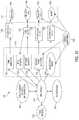
- FIG. 1is a schematic illustration of a low-field MRI system using a bi-planar magnet configuration
- FIGS. 2A-2Care schematic illustrations of single-layer and a multi-layer laminate techniques for producing a laminate panel, in accordance with some embodiments
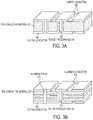
- FIG. 3Aillustrates an example portion of a laminate layer using copper as the material for the conductive traces patterned thereon;
- FIG. 3Billustrates an example portion of a laminate layer using aluminum as the material for the conductive traces patterned thereon;
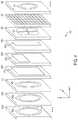
- FIG. 4shows an exploded view of example magnetic components of a low-field MRI system formed on layers of a multi-layer laminate panel, in accordance with some embodiments
- FIG. 5illustrates exemplary layers of a laminate panel integrating a B 0 magnet, in accordance with some embodiments
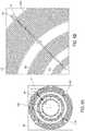
- FIGS. 6A and 6Billustrate an exemplary techniques for patterning multiple coils on a laminate layer of a laminate panel, in accordance with some embodiments
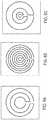
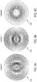
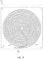
- FIGS. 7A-7Cshow spiral designs for a B 0 coil formed on at least one layer of a multilayer laminate panel in accordance with some embodiments
- FIGS. 8A-8Cshow circular designs for a B 0 coil formed on at least one layer of a multilayer laminate panel, in accordance with some embodiments
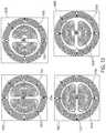
- FIG. 9A-9Cillustrate exemplary configurations for an x-gradient, a y-gradient coil and a z-gradient coil, respectively, in accordance with some embodiments
- FIG. 10illustrates exemplary layers of a laminate panel integrating a B 0 magnet and gradient coils, in accordance with some embodiments
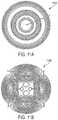
- FIGS. 11A and 11Billustrate exemplary shim coils that may be fabricated using lamination techniques discussed herein, in accordance with some embodiments
- FIG. 12shows a solenoid-based coil configuration for laminate panels formed using techniques described herein, in accordance with some embodiments
- FIG. 13shows a block diagram of exemplary components of a low-field MRI system, in accordance with some embodiments
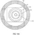
- FIGS. 14A-14Dillustrate hybrid designs for a B 0 magnet in accordance with some embodiments
- FIGS. 15A-15Cillustrate exemplary configurations for laminate panels formed using techniques described herein, in accordance with some embodiments
- FIG. 16is a schematic block diagram of components of a low-field MRI system, in accordance with some embodiments.
- FIG. 17illustrates a thermal management component, in accordance with some embodiments.
- FIG. 18is a block diagram of an RF signal chain for use with some embodiments.
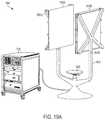
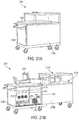
- FIGS. 19A and 19Billustrate a seated system configuration of a low-field MRI system using laminate panels, in accordance with some embodiments
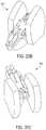
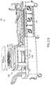
- FIGS. 20A-20Cillustrate a reclining system configuration of a low-field MRI system using laminate panels, in accordance with some embodiments
- FIGS. 21A-21Gillustrates portable transformable system configurations of a low-field MRI system using laminate panels, in accordance with some embodiments.
- FIGS. 22A-22Cillustrate exemplary helmets incorporating low field MRI magnetic components, in accordance with some embodiments.
- the MRI scanner marketis overwhelmingly dominated by high-field systems, and is exclusively so for medical or clinical MRI applications.
- the general trend in medical imaginghas been to produce MRI scanners with increasingly greater field strengths, with the vast majority of clinical MRI scanners operating at 1.5 T or 3 T, with higher field strengths of 7 T and 9 T used in research settings.
- high-fieldrefers generally to MRI systems presently in use in a clinical setting and, more particularly, to MRI systems operating with a main magnetic field (i.e., a B 0 field) at or above 1.5 T, though clinical systems operating between 0.5 T and 1.5 T are generally also considered “high-field.”
- low-fieldrefers generally to MRI systems operating with a B 0 field of less than or equal to approximately 0.2 T.
- high-field MRI systemsinclude improved resolution and/or reduced scan times compared to lower field systems, motivating the push for higher and higher field strengths for clinical and medical MRI applications.
- increasing the field strength of MRI systemsyields increasingly more expensive and complex MRI scanners, thus limiting availability and preventing their use as a general purpose and/or generally available imaging solution.
- contributing factors to the high cost of high-field MRIare expensive superconducting wires and the cryogenic cooling systems needed to keep the wires in a superconducting state.
- the B0 magnet for high field MRI systemsfrequently employ superconducting wire that is not only itself expensive, but requires expensive and complicated cryogenic equipment to maintain the superconducting state.
- Low-field MRhas been explored in limited contexts for non-imaging research purposes and narrow and specific contrast-enhanced imaging applications, but is conventionally regarded as being unsuitable for producing clinically-useful images.
- the resolution, contrast, and/or image acquisition timeis generally not regarded as being suitable for clinical purposes such as, but not limited to, tissue differentiation, blood flow or perfusion imaging, diffusion-weighted (DW) or diffusion tensor (DT) imaging, functional MRI (fMRI), etc.
- the inventorshave developed techniques for producing improved quality, portable and/or lower-cost low-field MRI systems that can improve the wide-scale deployability of MRI technology in a variety of environments beyond the large MRI installments at hospitals and research facilities. Some aspects of the inventors' contribution derive from their recognition that a significant factor contributing to the cost and complexity of both high-field and low-field MRI is the magnetics components needed to produce MR signals that are useable for imaging applications.
- MRIinvolves placing an object (e.g., all or a portion of a patient) to be imaged in a static, homogenous magnetic field B 0 to align atomic spins of atoms in the direction of the B 0 field.
- objecte.g., all or a portion of a patient
- B 0homogenous magnetic field
- superconducting magnets made from coils of superconducting wireare generally required to achieve the homogeneity of B 0 at field strengths employed in high-field MRI.
- the superconducting magnetsthemselves costly, but they generally require cryogenic cooling during operation, increasing the cost and complexity of high-field MRI scanners.
- gradient coilsare provided to spatially encode MR signals from the object, and transmit and receive coils are provided to generate a magnetic field Bi at a frequency related to the field strength of the magnetic field B 0 to cause atomic spins to change orientation and to detect MR signals emitted from the object upon realignment of the atomic spins with the magnetic field B 0 , respectively.
- these magnetic componentsare also relatively complex and expensive.
- low-field MRI systemsdo not require expensive superconducting magnets and/or the associated cryogenic cooling systems, and the reduced field strengths may facilitate reduction in the complexity and/or expense of other magnetic components in the system.
- some embodimentsare directed to low-field MRI systems having substantially less complex and expensive magnetic components, as discussed in further detail below.
- producing such magnetic components and manufacturing a system suitable for performing low-field MRI using conventional techniques for doing sowhile significantly less complex and expensive than high-field MRI, still may present technical challenges that increase complexity and expense.
- B 0 magnetsusing conventional techniques typically requires winding significant amounts of high-grade copper wire about a frame according to precise design specifications to produce coils capable of generating a magnetic field of satisfactory homogeneity at a desired field strength, a process which is relatively time consuming, expensive, susceptible to production deviation, and that generally does not scale well. Further issues arise with alignment of the B 0 magnets and alignment with other magnetic components, as discussed in further detail below.
- laminate techniquessimilar in some respects to those utilized in producing printed circuit boards, may be employed to fabricate one or more (or a portion of one or more) magnetic components of a low-field MRI scanner.
- one or more magnetic components (or portion thereof) for use in low-field MRIis provided as a laminate panel comprising one or more non-conductive layers and one or more conductive layers patterned to form the one or more magnetic components or portion thereof.
- laminaterefers herein to a plurality of superposed layers, typically involving at least one or more non-conductive layers and one or more conductive layers.
- laminateis generic to the types of materials used and indicates the affixing of multiple layers together, but does not specify any particular type of material or arrangement of materials used to produce the layers.
- panelgenerally describes a structure resulting from a laminate of multiple laminate layers and can be of any shape or size, and can include any number of layers.
- one or more B 0 coils, one or more gradient coils, one or more transmit/receive coils, and/or one or more shim coils, or any desired portions or combinations thereofmay be fabricated on a single laminate panel or distributed between multiple laminate panels, as discussed in further detail below.
- Utilizing laminate techniquesmay facilitate a cost-effective, scalable, flexible, repeatable and/or customizable approach to producing low-field MRI magnetics.
- the inventorshave appreciated that the precision achievable using laminate techniques allows for the design and manufacture of geometries, configurations and arrangements that are not possible using conventional techniques for manufacturing or producing the magnetics of an MRI system.
- exemplary low-field MRI systemsmay be implemented without using superconducting magnets and consequently without the associated cryogenic cooling apparatus, thereby significantly reducing the cost, complexity and size of the resulting MRI system.
- a solenoid coil formed of superconducting materialis used wherein the B 0 field generated is in the direction of the axis through the center of the solenoid.
- the solenoid coilis particularly well-suited for generating a homogenous field at high field strengths, this geometry not only increases the size of equipment, but requires that a patient be inserted into a cylindrical bore to be imaged. Thus, this geometry may be unsuitable for patients with claustrophobia and may be incapable of accommodating large patients.
- the solenoid coil geometry generally required to produce a suitable B 0 magnet for high-field MRIhas further limitations that prevent high-field MRI from being a practical and available general purpose imager.
- FIG. 1schematically illustrates a portion of a low-field MRI system 100 including a bi-planar magnet geometry that may be utilized to generate a B 0 field suitable for low-field MRI imaging, in accordance with some embodiments.
- the bi-planar magnetcomprises two outer coils 110 a and 110 b and two inner coils 112 a and 112 b .
- a magnetic fieldis generated in the direction indicated by the arrow to produce a B 0 field having a field of view between the coils that, when designed and constructed appropriately, may be suitable for low-field MRI.
- the bi-planar geometry illustrated in FIG. 1is generally unsuitable for high-field MRI due to the difficulty in obtaining a B 0 field of sufficient homogeneity for high-field MRI.
- the bi-planar B 0 magnet illustrated in FIG. 1provides a generally open geometry, facilitating its use with patients who suffer from claustrophobia that may refuse to be imaged with conventional high-field solenoid coil geometries.
- the bi-planar designmay facilitate its use with larger patients as a result of its open design and, in some instances, a generally larger field of view possible at low-field strengths and homogeneities.
- bi-planar B 0 magnet illustrated in FIG. 1provides a much less complex and lower cost B 0 magnet then what is possible for high-field MRI
- production of coils 110 a , 110 b , 112 a and 112 bis typically a relatively time-consuming and sensitive process that generally involves the repeated winding of copper wire around a support frame to produce a number of turns in accordance with a specific design for a given set of coils.
- a generally high-quality conductore.g., thick copper wire with high grade insulation
- an exemplary diameter of the outer coils in a bi-planar magnetmay be 220 cm with a typical number of turns being on the order of 50 turns or more, thereby requiring a substantial amount of conductor material (e.g., more than a kilometer of generally high grade wire for each side of the bi-planar magnet) that must be precisely wound in alignment over numerous turns.
- each coil in a pairshould be manufactured to be substantially identical to its corresponding coil in the pair to avoid degrading the homogeneity of the resulting B 0 field once the coils are energized.
- the coils on each sidee.g., coils 110 a , 112 a and coils 110 b , 112 b ) of the bi-planar magnet must also be carefully positioned and aligned to reduce inhomogeneity in the resulting B 0 field. Accordingly, manufacturing and installing such coils to produce a sufficiently homogeneous B 0 field for low-field MRI using conventional construction techniques tends to be relatively costly, time intensive and prone to error.
- laminate techniquesmay be utilized to fabricate a B 0 magnet or portion thereof for use in low-field MRI in place of (or in combination with) the conventional manufacturing techniques described above.
- the inventorshave appreciated and understood that the low-field characteristics of the B 0 magnetic component allows for fabrication of the B 0 magnetic component, or a portion thereof, using techniques previously unavailable for producing a B 0 magnet for MRI.
- the inventorshave appreciated that the lower power requirements and/or reduced thermal output of low-field MRI allows for production of magnetic components using laminate techniques, which were not available in the high-field context.
- a laminate panelcomprises at least one conductive layer patterned to form one or more B 0 coils, or a portion of one or more B 0 coils, capable of producing or contributing to a B 0 magnetic field suitable for low-field MRI.
- a B 0 coilrefers herein to any coil that provides or contributes to a B 0 magnetic field and may include one or more main B 0 coils, or portions thereof, one or more shim coils, or portions thereof, one or more correction coils, or portions thereof, etc.
- a laminate panelmay comprise a plurality of concentric coils to form one “side” of the pair of bi-planar B 0 coils illustrated FIG. 1 .
- a second laminate panelmay be similarly constructed to incorporate B 0 coils for the other “side” of the field of view in the bi-planar design.
- magnetic components used to generate a B 0 field for a low-field MRI systemmay be constructed using laminate panel techniques.
- B 0 field homogeneityis quite sensitive to relatively small changes in the parameters of the respective coils.
- small variations in the coil windings, position and alignment of the various coils, etc.result in field inhomogeneity of the B 0 field produced.
- Laminate techniquesare capable of producing magnetic components much more precisely and accurately than what is feasible using conventional techniques, facilitating a flexible, repeatable, and highly scalable technique for producing magnetic components, as discussed in further detail below.
- FIG. 1also schematically illustrates a pair of planar gradient coil sets 120 a , 120 b to generate magnetic fields to facilitate phase and frequency encoding for the portion of the low-field MRI system illustrated.
- MRI systemsencode received MR signals by systematically varying the B 0 field in a known manner using gradient coils to encode the spatial location of received MR signals as a function of frequency or phase.
- gradient coilsmay be configured to vary frequency or phase as a linear function of spatial location along a particular direction, although more complex spatial encoding profiles may also be provided by using nonlinear gradient coils.
- a first gradient coilmay be configured to selectively vary the B 0 field in a first (X) direction to perform frequency encoding in that direction
- a second gradient coilmay be configured to selectively vary the B 0 field in a second (Y) direction substantially orthogonal to the first direction to perform phase encoding
- a third gradient coilmay be configured to selectively vary the B 0 field in a third (Z) direction substantially orthogonal to the first and second directions to enable slice selection for volumetric imaging applications.
- Gradient coilsare designed to operate with a specific B 0 magnetic component (e.g., one or more B 0 coils as shown in FIG. 1 ) and, to operate satisfactorily, typically require relatively precise manufacture and subsequent alignment with the B 0 magnetic component.
- the inventorshave recognized that using laminate techniques to fabricate one or more gradient coils (or portions thereof) may facilitate a simpler more cost effective approach to manufacturing magnetics components of a low field MRI system.
- a laminate panelcomprises at least one conductive layer patterned to form one or more gradient coils, or a portion of one or more gradient coils, capable of producing or contributing to magnetic fields suitable for providing spatial encoding of detected MR signals when operated in a low-field MRI apparatus.
- the laminate panelmay comprise one or more conductive layers patterned to form one or more X-gradient coils (or portions thereof), one or more Y-gradient coils (or portions thereof) and/or one or more Z-gradient coils (or portions thereof).
- the laminate panel forming one or more gradient coils (or portions thereof)may be separate from a corresponding B 0 magnetic component, or may be formed in one or more layers of a same laminate panel.
- the one or more gradient coilsmay be formed by conductive layers shared with (but electrically isolated from) the one or more B 0 coils (or portions thereof) or may be formed in one or more conductive layers separate from the one or more B 0 coils (or portions thereof). Integration of one or more gradient coils (or portions thereof) with one or more B 0 coils (or portions thereof) in a laminate panel may facilitate a simpler more flexible approach to designing and manufacturing magnetic components for low-field MRI, further aspects of which are discussed below.
- MRI systemsstimulate and detect emitted MR signals using transmit and receive coils, respectively (often referred to as radio frequency (RF) coils).
- RFradio frequency
- the configuration of the transmit/receive coilsvaries with implementation and may include a single coil for both transmitting and receiving, separate coils for transmitting and receiving, multiple coils for transmitting and/or receiving, or any combination to achieve single channel or parallel MRI systems.
- the transmit/receive magnetic componentis often referred to as Tx/Rx or Tx/Rx coils to generically refer to the various configurations for the transmit and receive component of an MRI system.
- a laminate panelcomprises at least one conductive layer patterned to form one or more transmit and/or receive coils, or a portion of one or more transmit and/or receive coils, configured to stimulate an MR response by producing a Bi excitation field (transmit) and/or receive an emitted MR signal (receive) when operated in conjunction with magnetic components configured to produce a B 0 field and/or corresponding gradient fields for spatially encoding received MR signals.
- Such a laminate panelmay incorporate single transmit and/or receive coils (or portions thereof) or multiple transmit and/or receive coils (or portions thereof) for performing single channel or parallel MRI, respectively, and may be formed in a separate laminate panel or integrated in a laminate panel containing one or more B 0 coils (or portions thereof) and/or one or more gradient coils (or portions thereof), as discussed in further detail below.
- a low field MRI systemmay further include additional magnetic components such as one or more shim coils arranged to generate magnetic fields in support of the system to, for example, increase the strength and/or homogeneity of the B 0 field, counteract deleterious field effects such as those created by operation of the gradient coils, loading effects of the object being imaged, or to otherwise support the magnetics of the low field MRI system.
- additional magnetic componentssuch as one or more shim coils arranged to generate magnetic fields in support of the system to, for example, increase the strength and/or homogeneity of the B 0 field, counteract deleterious field effects such as those created by operation of the gradient coils, loading effects of the object being imaged, or to otherwise support the magnetics of the low field MRI system.
- the shim coilWhen a shim coil is operated to contribute to the B 0 field of an MRI system (e.g., to contribute to the field strength and/or to improve homogeneity), the shim coil functions as a B 0 coil of
- a low field MRI systemmay further include shielding component(s) arranged to suppress unwanted electromagnetic radiation in the environment and/or between components.
- shielding component(s)arranged to suppress unwanted electromagnetic radiation in the environment and/or between components.
- laminate techniquesmay be utilized to fabricate such components, for example, one or more shim coils (or portions thereof) and/or one or more shielding components, either by forming such components in separate laminate panel(s) or integrating such components in a laminate panel containing any one or combination of other magnetic components (or portions thereof) of a low field MRI system, as discussed in further detail below.
- laminate techniques for producing panels, plates, or “boards” containing one or more magnetic components of a low field MRI systemmay resemble, in principle, techniques conventionally used to fabricate printed circuit boards (PCBs) and certain limited printed electronics, though different in scale, power and thermal requirements, etc.
- Such laminate techniquesgenerally involve forming non-conductive and conductive layers of material and patterning the conductive and/or non-conductive layer(s) (e.g., by selectively removing and/or adding material) to produce a desired conducting pattern or “circuit.”
- Such techniquesare conventionally used to produce single-layer and multi-layer PCBs, for example, to provide electrical interconnection between discrete components mounted on the surface of the PCB, and have also been used to a limited extent to produce certain electronic components.
- laminate techniquesdo not present a viable solution in the high field context and have not been previously contemplated for use in producing magnetic components for MRI.
- laminate techniquesmay be used to fabricate one or more magnetic components of a low field MRI system, examples of which are discussed in further detail below.
- B 0 magnetcan be a time consuming process and may be susceptible to alignment errors and/or inhomogeneity due to manufacturing deviation, etc.
- conventional techniques for producing magnetic componentsmay be advantageously used in conjunction with laminate techniques described herein.
- one or more B 0 coils manufactured using conventional techniquesmay be supplemented with one or more B 0 coils fabricated using laminate techniques.
- FIG. 2Aschematically illustrates a laminate panel 200 that includes a single non-conductive layer 210 and a single conductive layer 212 formed on the non-conductive layer.
- the non-conductive layer 210(also referred to herein as a substrate) may be formed from any suitable material.
- substrate 210may be formed from any one or combination of suitable core materials, composites, adhesives and/or laminates may be utilized to form non-conductive layers and facilitate producing a laminate panel, including, but not limited to, FR4, ceramic, plastic, glass, polymide, epoxy, pre-impregnated composite fibers (pre-preg), multifunctional epoxy laminates such as 92 ML, or any other material(s) or combinations thereof having suitable properties.
- Substrate 210may be a single layer or constructed of multiple layers of non-conductive material, each layer of which may be made from a same or different non-conductive material. Layering the substrate may allow for construction of a substrate that utilizes beneficial properties of different materials. Substrate 210 may be constructed to any desired dimensions, having length, width and thickness suitable for a given design.
- conductive layer 212may be formed from any suitable conducting material.
- conductive layer 212may be a thin or thick film of copper or other suitable conductive material, a thick or extremely thick conductive layer (e.g., “extreme copper”), conductive plate, or any other type of conductive layer capable of being formed as a laminate on non-conductive substrate 210 by any suitable technique or process (e.g., via dip coating, electroplating, printing, molding, bonding, vacuum impregnating, pressing, dry adhesive, or any other suitable technique(s)).
- aluminummay be used as a conductor to take advantage of associated cost and weight reductions, as discussed in further detail below.
- conductive layer(s) 212may be patterned to form electrical conductors for desired portions of one or more magnetic components of a low-field MRI apparatus using any one or combination of various subtractive, additive and/or semi-additive processes.
- Subtractive processesselectively remove the conductive material (e.g., copper) from the conductive layer leaving a desired conductive pattern providing a desired conducting circuit or portion of a circuit using, for example, any of various lithographic processes including, but not limited to, chemical etching, photoengraving, etc.
- Such processesare performed by providing a resist material in the desired pattern (often referred to as a mask) and introducing the conductive layer to the corresponding etchant to remove the conductive material in locations not treated with the resist material.
- Another subtractive processinvolves milling away unwanted portions of the conductive layer leaving the desired conductive pattern.
- the subtractive processes described herein and/or any other suitable processmay be used alone or in any combination to fabricate the desired conductive pattern.
- Additive processesmay involve electroplating the desired conductive pattern on the substrate or “printing” the pattern using a conductive ink.
- electroplatingmay involve exposing photosensitive film masked in a desired pattern. The exposed pattern may then be introduced to a chemical bath to allow the pattern to be capable of metal ion bonding and then plated with a conductor (e.g., with copper) that bonds with the pattern sensitized in the chemical bath to form the desired conductive pattern.
- Additive processeshave the advantage that less conductive material is needed to form the desired conductive pattern than subtractive techniques. Other processes combine both subtractive and additive techniques to form the desired conductive pattern.
- one or more magnetic components fabricated using laminate techniquesmay require conductive layers to be fabricated at relatively large thicknesses, often referred to as “heavy copper,” (e.g., 5 oz/ft 2 -19 oz/ft 2 ) or “extreme copper,” (e.g., 20 oz/ft 2 -200 oz/ft 2 ), though the techniques apply regardless of the choice of conductor material.
- suitable techniques for patterning heavy or extreme copperinclude, but are not limited to, any one or combination of cupric chloride etch, ferric chloride etch, mechanical milling, plasma etch, laser etch, electro-discharge-machining (EDM), plating up, etc.
- any single technique or combination of techniques described hereinmay be utilized, or any other technique suitable for patterning a conductive layer on a non-conductive substrate and/or for producing a laminate panel may be used, as aspects of forming one or more magnetic components (or portions thereof) of a low field MRI system in a laminate panel are not limited to any particular technique or combination of techniques for doing so.
- FIG. 2Bschematically illustrates a laminate panel 205 that includes a plurality of non-conductive layers 210 and a plurality of conductive layers 212 formed between the non-conductive layers. Connections between the conductive layers 212 may be achieved by forming holes filled with a conductive material (e.g., plated through-holes) in the intervening non-conductive layers called “vias,” as described in more detail below.
- a conductive materiale.g., plated through-holes
- viase.g., plated through-holes
- FIG. 2Cillustrates a multi-layer panel formed by attaching together two laminate layers, each having a non-conductive layer 210 with a conductive layer laminated to both sides of the respective non-conductive layer.
- the multi-layer laminatesmay be attached using one or more adhesive layers 214 .
- Adhesive layer(s) 214may be any suitable adhesive or combination of materials such as pre-preg, dry adhesive, epoxy and/or any other suitable layer or combination of layers that, when activated (e.g., via heat and/or pressure) bonds the multi-layer laminates together. It should be appreciated that any configuration of conductive and non-conductive layering, adhesives, etc., using any one or combination of lamination techniques may be used to produce a desired laminate panel.
- FIG. 3Aillustrates a cross-section of a portion of an exemplary laminate layer on which conductive traces are formed by patterning copper conductors 350 on non-conductive material 325 and connected using vias between layers.
- the copper conductors 350may be patterned in any desired geometry and configured to form desired circuitry corresponding to one or more magnetic components (or portions thereof) of a low-field MRI system and/or any supporting electronics, control electronics, etc. Copper conductors on different layers may be electrically connected using vias such as plated through-hole vias 355 .
- the plated through-holesmay be formed by drilling holes through one or more layers of a laminate panel and using a suitable plating technique to form a conductive path through the non-conductive material to connect electrical conductors on different layers.
- viasmay be formed through an entire laminate panel, or may be formed through a subset of layers of a laminate panel, including to connect adjacent layers or multiple adjacent layers.
- a laminate layer of a laminate panelmay contain multiple vias arranged to connect to different layers of the laminate panel. For example, a layer having multiple components or portions of multiple components can be electrically isolated from each other and independently connected to conductors patterned on other layers as appropriate.
- the conductors patterned on layers of a laminate panelmay be connected in any way desired, and one or more layers may not include vias at all and therefore remain electrically isolated from other layers of the laminate panel.
- FIG. 3Billustrates a cross-section of a portion of a laminate layer on which a conductive pattern is formed using aluminum conductors 370 .
- Aluminum conductors 370may be formed using the same laminate techniques described herein.
- Aluminumhas a lower conductivity as compared to copper such that aluminum conductors 370 generally need to be formed with greater thickness than copper conductors 350 to obtain the same conductivity (e.g., an 80 mil aluminum layer may be needed in place of a 50 mil copper layer to achieve similar performance).
- FIG. 3Bfurther illustrates another method of providing vias between layers of a laminate panel using press-in pins.
- aluminum pin via 377may be inserted through a hole drilled between layers of a laminate panel. It should be appreciated that pin vias may be used to connect adjacent layers or multiple adjacent layers, including providing pin vias through an entire laminate panel. Similarly, pin vias may be used in any number and configuration desired to electrically connect the conductors patterned on the various layers of a given laminate panel. Though pin via 377 is shown in FIG. 3B in connection with the use of an aluminum conductor, it should be appreciated that pin vias may be utilized and formed from any suitable conductor.
- a laminate panelmay be fabricated using a combination of conductors such that one or more components or portions thereof are formed using a first conductor (e.g., copper) and one or more components or portions thereof are formed using a second conductor (e.g., aluminum).
- a first conductore.g., copper
- a second conductore.g., aluminum
- any suitable conductormay be used to pattern desired magnetic and/or electrical components of a low-field MRI system, as the techniques described herein are not limited for use with any particular conductor or combination of conductors.
- laminate techniquesare relatively precise and accurate, with certain processes capable of yielding precision and accuracy at the mil, micron or even sub-micron level.
- using laminate techniques to fabricate one or more magnetic components (or portions thereof)may reduce or eliminate much of the complexity and difficulty in manufacturing, aligning and installing magnetic components involved when using conventional techniques.
- conductive layer(s) 212may be patterned to form one or more magnetic components of a low field MRI system (e.g., one or more coils of a B 0 magnetic component, or desired portions thereof, one or more gradient coils, one or more transmit/receive coils, one or more shim coils, one or more shielding layers, etc.) to provide a simpler, more flexible, reliable and scalable mode of producing magnetic components for MRI, some specific examples of which are illustrated in FIG. 4 .
- Multiple low-field MRI componentsmay be integrated on a single panel or distributed between multiple panels to facilitate manufacture of the components according to a desired configuration, as discussed in further detail below.
- FIG. 4illustrates a schematic view of an exemplary multi-layer laminate panel 400 for use with a low-field MRI system, in accordance with some embodiments.
- laminate panel 400is depicted as such to illustrate some examples of components that may be fabricated via laminate techniques.
- a laminate panelneed not include all of the components illustrated in FIG. 4 , and any one or more of the illustrated components may be omitted as desired. That is, a laminate panel may include any one or combination of the exemplary layers illustrated in FIG. 4 to form any one or combination of components (or portions thereof) in the laminate panel.
- a laminate panelmay include other layers not illustrated in FIG. 4 (e.g., one or more layers for thermal management, one or more interconnect layers, one or more layers having control electronics or other electronic components, etc.).
- the illustrated componentsmay be formed in one or multiple layers, and separate components may be formed on layers shared with other components, or formed on separate layers independent from other components.
- the magnetic components illustrated in FIG. 4are shown schematically without limitation on geometry of the magnetic components, or the number of layers on which they may be fabricated.
- the exemplary layers illustrated in FIG. 4 and described hereinshould be understood to represent either a single laminate layer composed of at least one non-conductive layer and at least one conductive layer, or multiple such laminate layers, each composed of one or more non-conductive layers and one or more conductive layers. Accordingly, unless otherwise specified, a layer refers to one or more laminate layers.
- FIG. 4showing the various components that may be fabricated within panel 400 are used to generically represent the respective component and are not intended to depict any particular geometry or configuration.
- the components illustrated in FIG. 4may be patterned according to any desired geometry and configuration, as the techniques described herein for integrating one or more magnetic components within a laminate panel are not limited for use with any particular geometry, configuration or arrangement. Some examples of suitable geometries that may be utilized are discussed without limitation in further detail below.
- exemplary laminate panel 400includes a plurality of B 0 layers ( 410 a , 410 b ) having one or more B 0 coils ( 411 a , 411 b ) formed thereon.
- the B 0 coilsare configured to generate at least a portion of a B 0 field for the low-field MRI system when an appropriate current is applied to the coil(s).
- each B 0 layerincludes one or more turns of a conductive trace patterned on the conductive layer to generate a portion of a desired B 0 field.
- layer 410 ahas patterned thereon a coil 411 a , which may be patterned according to any desired geometry.
- coil 411 amay be patterned according to a generally circular geometry have one or more turns of conductive traces.
- Coil 411 amay be electrically connected to coil 411 b patterned on layer 410 b (e.g., by a via between the layers), which also may be of any desired geometry (e.g., a generally circular coil having one or more turn of a conductor).
- any suitable number of layers having B 0 coils formed thereonmay be interposed between and electrically connected to layers 410 a and 410 b (e.g., 1, 10, 20, 50 or more layers, etc), each having one or more respective coils formed thereon that, when energized with a suitable current, provides at least a portion of a B 0 field configured for use in low-field MRI.
- each layermay have a single coil or multiple coils, and each coil may be patterned to have any number of turns formed thereon to achieve the magnetic and/or electric properties of a desired coil design.
- B 0 coilshaving arbitrary geometries and configurations not practicable or possible using conventional techniques for manufacturing B 0 coils for low-field MRI systems, allowing for coil designs of virtually any geometry, configuration and/or arrangement.
- at least some B 0 layers on which one or more coils, or portions thereof, are formedmay be patterned using different coil geometries than other layers to achieve a desired B 0 field.
- Some B 0 layersmay have formed thereon one or more coils that can be independently controlled to tune the B 0 field for different applications and environments, or to adjust the B 0 field to calibrate or otherwise achieve a B 0 field of desired strength and/or homogeneity, as discussed in further detail below.
- the selection of a particular coil geometry or combination of coil geometries and the arrangement and distribution of the coils within a laminate panelmay depend, at least in part, on a desired B 0 field to be generated for use with low-field MRI applications.
- one or more laminate layers having the same or different B 0 coil designmay be connected by one or more vias connecting the conductive traces on the multiple layers.
- the locations of the viasmay be selected to minimize their effect on the homogeneity of the resultant B 0 field and/or to generally optimize one or more electrical properties of the energized coil.
- B 0 coil designsthat may be used to form, at least in part, a B 0 magnet for use in low-field MRI, are described in further detail below.
- a B 0 magnet(or any portion thereof) may be fabricated in laminate panel form reliably and with high fidelity in accordance with the design specifications for a particular B 0 magnet to achieve a B 0 field of desired strength and homogeneity. Additionally, the ability to distribute one or more B 0 coils forming a B 0 magnet (or a portion thereof) over multiple layers of a laminate panel allows for optimizing the parameters of the B 0 magnet to generate a desired B 0 field in a manner not possible using conventional techniques for producing a B 0 magnet.
- Simulationsmay be used to select among numerous geometries, configurations and/or arrangements (e.g., the position, geometry or other properties of electrical conductors on each layer contributing the B 0 field may be generally optimized) to produce a desired B 0 field.
- the resulting designmay then be precisely and accurately fabricated using suitable laminate techniques.
- one or more laminate layersmay include passive magnetic component(s), such as one or more layers patterned with magnetic materials, to facilitate the generation of a desired B 0 field with reduced power requirements, or to produce a higher B 0 field using the same power requirements as needed without the use of magnetic materials.
- laminate panel 400may include one or more laminate layers 415 patterned with ferrous, or other magnetic materials, arranged to form a magnetic component 416 that contributes to the magnetic field generated by one or more B 0 coils to achieve a desired B 0 field. Because such magnetic materials produce or tailor a magnetic field without needing a power source to provide current to produce a magnetic field, a desired B 0 field may be produced with reduced power requirements.
- magnetic materialscan be used to produce a higher B 0 field without a corresponding increase in power requirements, magnetic materials may facilitate the construction of a low-field MRI system having a higher B 0 field, potentially exceeding 0.2 T (e.g., between 0.2 T and 0.5 T).
- Magnetic component(s) 416 formed on one or more layers 415may include any one or combination of materials having relatively high magnetic permeability ( ⁇ ) to assist in producing or tailoring a B 0 field of desired field strength and/or homogeneity.
- Magnetic component(s) 416may be formed by one or more patterned layers, provided as a sheet, or other otherwise manufactured and incorporated within one or more laminate layers to produce a desired magnetic field. As discussed above, the use of passive magnetic components can reduce the power requirements needed to produce a given B 0 field.
- a portion of a desired B 0can be produced passively (e.g., without requiring a power source to operate the components), the burden on the active magnetic components (e.g., the one or more a desired B 0 coils) can be reduced.
- the active magnetic componentse.g., the one or more a desired B 0 coils
- one or more B 0 coilscan be operated with reduced current to produce, in combination with magnetic component(s) 16 , a B 0 field having a desired field strength and/or homogeneity.
- Reducing the power requirements of the active magnetic componentssimplifies the cost and complexity of the power electronics driving the magnetic components, results in a corresponding reduction in the thermal output of the laminate panel, and also may otherwise ease the constraints on the active magnetic components in generating a B 0 field of desired strength and/or homogeneity.
- a laminate panelmay further comprise at least one conductive layer patterned to form one or more gradient coils, or a portion of one or more gradient coils, capable of producing or contributing to magnetic fields suitable for providing spatial encoding of detected MR signals when operated in a low-field MRI system.
- laminate panel 400includes a plurality of laminate layers ( 420 a , 420 b , 420 c ) on which gradient coils ( 421 a , 421 b , 421 c ) are formed.
- Layer(s) 420 aincludes a conductive trace patterned to form all or a portion of a Z-gradient coil 421 a
- layer(s) 420 bincludes a conductive trace patterned to form all or a portion of a Y-gradient coil 421 b
- layer(s) 420 cincludes a conductive trace patterned to form all or a portion of an X-gradient coil 421 c .
- the depiction of gradient coils 421 a , 421 b and 421 c in FIG. 4is meant to generically represent gradient coils of any suitable geometry using any number and configuration of layers to provide the one or more desired gradient coils.
- a Z-gradient coilmay be formed, at least in part, in one or more layers using a generally circular geometry and an X-gradient coil and a Y-gradient coil may be formed, at least in part, in one or more layers using a generally rectangular geometry such as via one or more conductors patterned as a grid (e.g., similar to the geometry schematically illustrated in FIG. 1 ).
- the conductors for the gradient coilsmay be distributed across one or multiple layers in any combination as desired to produce integrated gradient coils, either with or without other magnetic components of a low field MRI system, and either sharing layers with other magnetic components and/or patterned on separate layers of a laminate panel.
- At least one layer of the laminate panelmay include both B 0 coils (or a portion thereof) and gradient coils (or a portion thereof) that may be selectively controlled to provide desired magnetic field characteristics for low-field imaging applications.
- at least a portion of the same conductive trace on a layer of a laminate panelmay function as a B 0 coil or as a gradient coil depending on how the coil is operated.
- a gradient coilmay be distributed over multiple layers and according to some embodiments, multiple gradient coils (or portions thereof) may be formed in a single layer (e.g., one or more of X, Y and/or Z gradient coils), as the techniques described herein are not limited to any particular manner of distributing magnetic component(s) over multiple layers of a laminate panel or multiple laminate panels. It should be appreciated that one or more gradient coils fabricated using laminate techniques may be utilized in connection with one or more other magnetic components fabricated using laminate techniques (e.g., by integrating the one or more gradient coils in a shared or separate laminate panel), or may be utilized in connection with one or more other magnetic components fabricated using conventional techniques as part of a low field MRI system.
- a laminate panelmay further comprise at least one conductive layer patterned to form one or more transmit and/or receive coils, or a portion of one or more transmit and/or receive coils, configured to stimulate MR response by producing a Bi excitation field (transmit) and/or to receive emitted MR signals (receive) when operated in conjunction with the coils configured to produce a B 0 field and corresponding gradient fields.
- a laminate panelmay incorporate single transmit and/or receive coils (or portions thereof) or multiple transmit and/or receive coils (or portions thereof) for performing single channel or parallel MRI.
- laminate panel 400includes layer(s) 430 on which all or a portion of a transmit/receive coil 431 is formed.
- any suitable geometrymay be used to pattern the transmit/receive coil or set of transmit/receive coils.
- a spiral-shape conductormay be patterned in one or more layers to form one or more transmit/receive coil (or portions thereof).
- a substantially rectangular geometrymay be utilized to fabricate one or more transmit and/or receive coils using laminate techniques.
- transmit and receive coilsmay be formed in one or more layers using different respective geometries.
- multiple layers and/or multiple laminate panelsmay be used to collectively form a transmit/receive coil and/or set of transmit/receive coils for use in a low field MRI system.
- one or more transmit/receive coils fabricated using laminate techniquesmay be utilized in connection with one or more other magnetic components fabricated using laminate techniques (e.g., by integrating the one or more other magnetic components in a shared or separate laminate panel), or may be utilized in connection with one or more other magnetic components fabricated using conventional techniques as part of a low field MRI system.
- a laminate panelmay further comprise at least one conductive layer patterned to form one or more electromagnetic shields arranged to prevent electromagnetic energy from the environment and/or generated from components of the MRI system from disturbing the magnetic fields generated by the MRI magnetics and/or for otherwise shielding the apparatus from electromagnetic interference.
- laminate panel 400includes layer(s) 440 used to provide electromagnetic shielding.
- shielding layer(s) 440may be formed by patterning a conductor mesh in one or more layers of laminate panel 400 , though it should be appreciated that shielding may be provided using any suitable conductor pattern to form any desired geometry, which geometry may be selected based on where the respective shielding is provided and/or characteristics of the electromagnetic interference the particular shielding is employed to suppress or eliminate.
- Electromagnetic shieldingmay be configured to provide active shielding or passive shielding, and embodiments are not limited in this respect.
- shielding formed on multiple layers of a laminate panelare connected using one or more vias. Accordingly, at least some shielding for a low field MRI system may be integrated into one or more laminate panels in which one or more magnetic components are fabricated, either on one or more separate layers or on one or more layers on which another magnetic component (or portion thereof) is formed.
- Electromagnetic shieldingmay include static or dynamic shielding of magnetic fields, electric fields, or both.
- Shim coils arranged to facilitate the production of desired magnetic fieldsmay also be patterned on one or more layers of a laminate panel.
- a laminate panelmay comprise at least one conductive layer patterned to form one or more shim coils, or a portion of one or more shim coils, arranged to produce or contribute to magnetic field(s) and adapted to improve the homogeneity of the B 0 field generated by one or more B 0 coils, to otherwise improve the B 0 field within a given field of view and/or to counteract other magnetic fields that negatively impact the B 0 field.
- laminate panel 400includes layer(s) 450 on which one or more shim coils 452 (or portions thereof) are formed.
- the at least one shim coilmay be formed by conductive layers shared with (but electrically isolated from) the at least one B 0 coil (or portions thereof) or may be formed in one or more conductive layers separate from the at least one B 0 coil (or portions thereof).
- shim coils fabricated using laminate techniquesmay be utilized with other components fabricated using laminate techniques (e.g., by integrating the shim coils in a shared or separate laminate panel) or utilized with other components manufactured using conventional techniques as part of a low field MRI system.
- multiple low-field MRI componentsmay be formed on a single layer (i.e., a single laminate layer) of a laminate panel. That is, multiple magnetic components or portions of multiple magnetic components may be patterned on the same conductive layer of a single laminate layer.
- the conductive layer of a single laminate layermay be patterned to form one or more B 0 coils (either forming or contributing to a complete B 0 magnet) and one or more gradient coils or portion of one or more gradient coils.
- a single laminate layer of a laminate panelmay be patterned to form all or a portion of a gradient coil and all or a portion of a transmit/receive coil.
- the gradient coil and the transmit/receive coil (or portions thereof)may share at least some conductive elements formed on the laminate layer, or the gradient coil and the transmit/receive coil (or portions thereof) may be formed separately on the same laminate layer (e.g., electrically isolated from one another).
- a single laminate layer of a laminate panelmay be patterned to form all or a portion of one or more B 0 coils and all or a portion of one or more shim coils used to tune the homogeneity of the B 0 field for the low-field MRI system.
- the shim coil(s) and the B 0 coil(s)may share at least some conductive elements formed on the laminate layer or the shim coil(s) and the B 0 coil (or portions thereof) may be formed separately on the same laminate layer (i.e., electrically isolated from one another). It should be appreciated that any combination of components (or portions thereof) may be similarly fabricated in one or more shared laminate layers as desired according to a specific design, as the aspects are not limited in this respect.
- some conductors formed on laminate panels in accordance with some embodimentsmay be configured to perform multiple functions typically characteristic of functions performed by separate MRI components. By repurposing the same conductors to perform different functions and/or by sharing laminate layers of a laminate panel between multiple components or portions of multiple components, the dimensions and costs associated with manufacturing a laminate panel may be reduced.
- any suitable ordering of layersmay be used. That is, when multiple magnetic components (or portions thereof) are integrated into a laminate panel, any ordering of the laminate layers may be used to achieve a desired sequence of the integrated magnetic components.
- the configuration of the layers and components formed thereonmay be selected based, at least in part, on design considerations for optimizing one or more system and/or imaging parameters including, but not limited to, power consumption, gradient linearity, B 0 field homogeneity, gradient strength, RF strength, thermal considerations, etc.
- one or more layers comprising all or a portion of one or more B 0 coilsmay be located as the innermost layer(s) of the laminate panel to reduce power consumption of the low-field MRI system.
- one or more outer layers of the laminate panelmay be patterned to provide electromagnetic shielding. Accordingly, any ordering of layers of a laminate panel may be used, as the techniques described herein are not limited for use with any particular configuration in this respect.
- a laminate panelmay include any one or combination of components, or desired portions thereof.
- at least some of the exemplary componentsare provided separate from laminate panel(s) (e.g., using conventional manufacturing techniques for those components).
- some embodimentsinclude laminate panel(s) having one or more B 0 coils formed thereon, with other components of the low-field MRI system being provided separate from the laminate panel(s).
- laminate panelshaving one or more gradient coils formed thereon, with other components of the low-field MRI system being provided separate from the laminate panels.
- the main magnetic field B 0 for the low-field MRI systemmay be manufactured using conventional techniques (e.g., as described above in connection with the bi-planar B 0 coil architecture in FIG. 1 ), and the transmit/receive coil may be provided by a helmet-based and/or surface-based coil placed around or near the object to be imaged.
- laminate panelsmay have formed thereon both one or more B 0 coils and one or more gradient coils (or portions thereof), with other components of the low-field MRI system being produced separate from the laminate panel(s).
- laminate panels manufactured in accordance with techniques described hereinmay include any suitable number of layers on which any one or combination of low-field MRI components (or portions thereof) are formed, and such laminate panel(s) may be utilized in connection with any number of other laminate panel(s) or any one or combination of other components produced using other techniques, as the aspects are not limited in this respect.
- a hybrid approachmay be used wherein one or more magnetic components are implemented with a portion being fabricated using laminate techniques and a portion produced using conventional techniques.
- FIG. 5illustrates a multi-layer laminate panel 500 having a B 0 coil fabricated therein, in accordance with some embodiments.
- FIG. 5shows some examples of how portions of a B 0 coil may be distributed across multiple layers of a laminate panel to produce, when energized, a magnetic field contributing to a B 0 field suitable for performing low-field MRI.
- each layermay (but need not) include other components, including other magnetic components (e.g., one or more gradient coils, transmit/receive coils, shim coils, etc.), as discussed in further detail below.
- other magnetic componentse.g., one or more gradient coils, transmit/receive coils, shim coils, etc.
- Exemplary laminate panel 5comprises fourteen laminate layers over which portions of a B 0 magnet are distributed by patterning the respective conductive layers accordingly.
- the conductive patterns provided on example layersare illustrated by a generally circular coil, the width of which denotes in a representative manner the number of turns forming the respective coil.
- the coilsare represented with solid and dashed lines to indicate that, when energized, current through coils represented with solid lines flows in the opposite direction as current through coils represented with dashed lines (e.g., clockwise versus counter-clockwise, or vice versa).
- Example laminate panel 500comprises coils 510 A, 510 B, 510 C, 510 D, 510 E, 510 E, 510 F and 510 G fabricated thereon and distributed, by way of example only, in the manner described below.
- Each of the exemplary layers 1-14 in FIG. 5have fabricated thereon a coil 510 A comprising a plurality of turns, for example, twenty turns of conductive traces each. That is, as shown in the depicted layers, each of the fourteen layers may be patterned to form a respective outer coil having twenty turns of conductive traces. Each coil 510 A may be connected to coil 510 A in the subsequent layer using a one or more vias between the layers (e.g., plated through-holes, pins, or other suitable conductive vias).
- one or more of the outer coils 510 Amay be electrically isolated from other coils 510 A and may, for example, be configured to be independently energized (e.g., one or more of coils 510 A may be utilized as a shim coil).
- Each of the first six layerse.g., Layers 1-6 illustrated in FIG. 5 ) consist of outer coil 510 A with respect to the integrated B 0 coil, though other components (including other magnetic components) may be fabricated thereon in addition.
- each of layers 7-14also have fabricated thereon a respective coil 510 B, which as denoted by the dashed lines, may conduct current in an opposite direction as coils 510 A when operated.
- each coil 510 Bincludes a number of turns less than the number of turns in coils 510 A formed on respective layers. As indicated by the decreasing line width used to represent coils 510 B, the number of turns of conductive traces forming the respective coil may also decrease (or otherwise vary) across the layers on which the coils are distributed.
- coils 510 B in layers 7 and 8may comprise 11 turns of conductive traces each, coils 510 B fabricated in respective layers 9-11 may be formed with 10 turns, coil 510 B fabricated in layer 12 may be formed with 9 turns, and coils 510 B fabricated in respective layers 13 and 14 may be formed with 8 turns. It should be appreciated that the turn configuration is exemplary, and that the number of turns and how the number of turns vary (or remain constant) are not limited in any respect.
- each of layers 7-14also have fabricated thereon a respective coil 510 C, which as denoted by the solid lines representing the coils, may conduct current in the same direction as coils 510 A when operated.
- each coil 510 Cincludes a number of turns less than the number of turns forming coils 510 B in the respective layer, which number may vary or remain the same across laminate layers on which coils 510 C are patterned.
- coils 510 C fabricated in respective layers 7-10may be formed with 6 turns
- coil 510 C fabricated in layer 11may be formed with 5 turns
- coils 510 C fabricated in respective layers 12-14may be formed with 4 turns.
- this arrangementis merely exemplary and the number of turns and how they vary (or remain constant) are not limited by this example arrangement.
- Each of layers 7-11also have fabricated thereon a respective coil 510 D and a respective coil 510 E, each of layers 7-9 have fabricated thereon a respective coil 510 F, and each of layers 7 and 9 have fabricated thereon a respective coil 510 G and a respective coil 510 H.
- successive coilsalternate the direction in which they conduct current when operated, and each successive coil includes a number of turns of conductors less than the preceding coil.
- this configurationis merely exemplary and the direction in which current is conducted, the number of turns in each coil, and the number of coils on each layer of a laminate panel may be selected as desired to produce or contribute to a B 0 field for low field MRI.
- the conductors forming the exemplary coils illustrated in FIG. 5may be connected together intra-layer (as discussed in further detail below) and/or connected inter-layer using conductive vias between the layers. Furthermore, one or more of the coils illustrated in FIG. 5 may be patterned in isolation and capable of being independently energized. In this manner, such coils may be used as shim coils that can be operated as needed to improve the homogeneity of the resulting B 0 field in a given environment or under given loading conditions (e.g., during calibration of the low-field MRI system).
- FIG. 6Aillustrates an exemplary layer 605 of a laminate panel on which a B 0 coil is patterned (e.g., layer 605 may be similar to layer 12 illustrated in FIG. 5 ).
- Layer 605comprises coils 610 A, 610 B and 610 C, each having a plurality of turns of a conductive trace (e.g., 20 turns, 10 turns and 5 turns, respectively).
- FIG. 6Billustrates region 645 indicated in FIG. 6A enlarged to show further detail regarding the conductive trace or track patterned on layer 605 .
- coils 610 A, 610 B and 610 Care formed by a single conductive trace 615 patterned such that when electrical current is provided to conductive trace 615 , current is conducted in alternating counter-clockwise and clockwise directions with respect to coils 610 A, 610 B and 610 C.
- coil 610 Aconducts current in a counter-clockwise direction
- coil 610 Bconducts current in a clockwise direction
- coil 610 Cconducts current in a counter-clockwise direction.
- conductive trace 615may be patterned to implement any desired configuration with respect to the direction in which current is conducted.
- layers on which multiple coils are fabricatedmay be patterned such that current is conducted in the same direction through each coil, or the direction of current conduction may be changed through one or more desired coils, as techniques described herein are not limited for use with any particular configuration of conductors or direction of current flow.
- FIGS. 6A and 6Balso illustrate exemplary vias, of which via 675 is labeled in 6 B.
- These viasconnect conductive traces patterned on one laminate layer with conductive traces patterned on one or more other laminate layers (e.g., as illustrated by exemplary vias shown in FIGS. 3A and 3B described above).
- Viasmay be provided to connect conductive traces in adjacent laminate layers and/or may be provided through multiple layers to connect conductive traces patterned on any number of desired laminate layers. Accordingly, the conductive traces patterned on different layers of a laminate panel may be connected in any manner to produce desired circuitry for magnetic components (or other electronic components) fabricated within a laminate panel.
- FIGS. 7 and 8schematically illustrate non-limiting examples of B 0 coil designs that may be realized using the laminate techniques described herein. Unlike B 0 coil designs that can be practically realized for low-field MRI systems using conventional production techniques, which typically involve winding a square or circular conductor around a rigid support structure, other designs may be realized by virtue of the flexibility and precision of laminate processes. For example, conductive traces for a B 0 coil formed using laminate techniques may be fabricated and patterned, generally speaking, according to any desired dimensions and according to any desired geometry.
- the conductive pathscan be fabricated having relative dimensions generally not feasible using conventional wire conductors, and can be patterned according to geometries that are not practical, if even possible, using conventional manufacturing techniques.
- laminate techniquesmay facilitate the manufacture of more optimal coil designs, not only for the B 0 magnet, but for other magnet components as well (e.g., gradient coils, transmit/receive coils, shim coils, etc.).
- laminate techniquesallow a coil to be distributed over multiple (and in some designs relatively numerous) layers
- the dimensions, position, geometry, etc. of the portion of the coil in each given layermay be selected to generally optimize the resulting magnetic field.
- the inventorshave developed simulations to vary one or more parameters of the conductive pattern on each layer to determine a generally optimal solution regarding any one or combination of conductor dimension, position, geometry, number of turns, and/or any other parameter(s) of the conductive pattern on each layer that impacts the resulting magnetic field.
- Different MRI applicationsmay have different optimal solutions such that laminate techniques may be utilized to design and implement low-field MRI systems tailored for particular MRI applications.
- FIGS. 7A-7Cillustrate spiral B 0 coil designs comprising a plurality of turns, which may for example, be patterned on a single layer of a laminate panel or distributed over multiple laminate layers and connected using appropriately placed vias.
- FIG. 7Aillustrates a relatively wide spiral trace of conductive material patterned on one or more laminate layers.
- FIG. 7Bshows a spiral B 0 coil design wherein the width of the conductive path is thinner than the conductive path illustrated in FIG. 7B , but the number of turns is greater.
- FIG. 7Cshows a spiral B 0 coil design having a non-uniform density of turns of the spiral (i.e., the spiral geometry becomes tighter as it moves inward).
- variable density spiral B 0 coilsmay reduce the amount of power required to produce a desired strength B 0 field compared to a given circular coil designs.
- Manufacture of such variable spiral density B 0 coilsare typically impractical or not feasible using conventional wire-wrapping techniques. It should be appreciated that other spiral-based B 0 coil designs are also possible and the geometries and configurations illustrated herein are merely exemplary of possible coil designs.
- FIGS. 8A-8Cillustrate concentric ring B 0 coil designs comprising a plurality of turns that may be patterned on a single laminate layer of a laminate panel or distributed over multiple laminate layers using appropriately placed vias.
- FIG. 8Aillustrates a plurality of connected circular traces of conductor material formed on one or more laminate layers and having a uniform density with respect to the turns of the conductor.
- FIG. 8Bshows a B 0 coil design where both the number and density of the turns of the B 0 coil formed on the laminate layer are increased compared to the design of FIG. 8A , while maintaining a uniform density of the turns.
- FIG. 8Cshows a B 0 coil design having a non-uniform density of turns of the concentric coils. It should be appreciated that other circular-based B 0 coil designs are also possible, for example, the exemplary B 0 coil configurations described above in connection with FIGS. 5, 6 and 10 , and embodiments are not limited in this respect.
- FIGS. 9A-9Cillustrate exemplary x-gradient, y-gradient and z-gradient coils in accordance with some embodiments.
- FIG. 9Aillustrates an example of an x-gradient coil 920 A that may be patterned on a single laminate layer or distributed over multiple laminate layers of a laminate panel.
- X-gradient coil 920 Amay, for example, be configured to perform frequency encoding.
- y-gradient coil 920 Bmay be patterned on a single or multiple laminate layers and, for example, be configured to provide phase encoding
- z-gradient coil 920 Cmay be patterned on one or more laminate layers and, for example, be configured to provide localization of image slices.
- the gradient coilsmay be arranged and configured to perform any suitable spatial encoding. It should be appreciated that patterns illustrated in FIG. 9A-9C are merely exemplary and any configuration or geometry may be used to implement gradient coils for a low field MRI, as the techniques described herein are not limited to any particular design or configuration for implementing gradient coils.
- FIG. 10illustrates an example wherein gradients coils are fabricated on at least some of the same layers as coils that form, at least in part, a B 0 magnet.
- FIG. 10illustrates six laminate layers of a laminate panel wherein x-gradient coils 1020 A, y-gradient coils 1020 B, and z-gradient coils 1020 C are patterned in the same layers as portions of a B 0 magnet (e.g., layers having patterned thereon one or more B 0 coils or portions thereof).
- coils 1010 Amay be similar to coils 510 A illustrated in FIG. 5 .
- regions of a laminate layer in the center of such B 0 coilsmay be utilized to pattern one or more gradient coils, or portions thereof.
- x-gradient coils 1020 Amay be patterned on layers 1000 A and 1000 B
- y-gradient coils 1020 Bmay be patterned on layers 1000 C and 1000 D
- z-gradient coils 1020 Cmay be patterned on layers 1000 E and 1000 F along with B 0 coils 1020 A patterned on respective layers of the laminate panel.
- gradient coilsmay be integrated in a same laminate panel with B 0 coils for a low-field MRI B 0 magnet in other ways, including patterning gradient coils, in whole or in part, on at least some separate laminate layers of the laminate panel, as integrating multiple magnetic components in a laminate panel is not limited to any particular manner of doing so. By sharing layers between magnetic components, the number of layers may be reduced, thus reducing the cost of manufacturing a laminate panel.
- one or more shim coilsmay be fabricated within a laminate panel along with one or more other magnetic components of a low field MRI system.
- FIGS. 11A and 11Billustrate example shim coils that may be patterned on one or more layers of a laminate panel to produce a magnetic field to contribute to or assist in providing a B 0 field of desired strength and homogeneity.
- shim coil 1150 Amay be patterned in one or more laminate layers to produce, when energized, a corresponding magnetic field.
- Coil 1150 Amay be configured to be independently energized by, for example, electrically isolating coil 1150 A from other active components provided within the same laminate panel or the same laminate layer so that coil 1150 A can be powered separately.
- Coil 1150 B illustrated in FIG. 11Bshows a different exemplary geometry for providing a shim coil integrated within a laminate panel. Similar to shim coil 1150 A, shim coil 1150 B may be configured to be independently operated.
- shim coilsmay be provided in any manner and configuration to contribute magnetic fields that facilitate the production of a B 0 field of desired strength and homogeneity.
- coil 1150 A and/or coil 1150 Bmay be patterned on a single layer or distributed across multiple layers, and each coil may be patterned on a layer alone or may share one or more layers with one or more other components, or portions thereof.
- any number of shim coils having any desired geometrymay be fabricated within a laminate panel, as the aspects are not limited in this respect.
- one or more shim coilsare fabricated within a laminate panel separate from other magnetic components of a low field MRI system.
- shim coilsmay be provided in different geometries and/or locations such that different combinations of shims coils may be selectively activated in response to a given environment in which the system is being operated.
- the ability to dynamically choose a combination of shim coils to operatemay facilitate the production of low field MRI systems capable of being deployed in a transportable or cartable fashion.
- shim coils that contribute to a B 0 fielde.g., to improve homogeneity
- one or more passive shimsare utilized to produce a magnetic field to contribute to a B 0 field of desired strength and homogeneity.
- magnetic materialsmay be utilized to produce magnetic fields without requiring a source of power to do so.
- one or more layers patterned with magnetic materialsmay be provided as passive shims to assist in producing the desired B 0 field.
- passive shimsmay be provided in any number, arrangement and geometry, and may be patterned on a single or multiple layers, either alone or on layers shared with one or more other components, as the aspect relating to providing passive shims are not limited to any particular configuration, geometry or arrangement.
- Passive shimsmay be provided using separate shim elements comprised of magnetic materials of any desired geometry. Such shim elements may be incorporated into a laminate panel by affixing the elements to the panel (e.g., using an adhesive or by other means of attachment) at desired locations and/or such shim elements may be arranged separate from the laminate panel at desired locations, as the aspects are not limited to any particular manner of incorporating one or more passive shims into a low-field MRI system.
- laminate techniquesmay be used to produce magnetic component(s) in any number of different combinations and configurations.
- laminate panel techniquesmay also be used to implement a low-field MRI system according to solenoid B 0 coil designs, wherein the B 0 field generated is oriented along the axis through the center of a solenoid coil, a design frequently used to implement high-field MRI systems.
- one or more solenoid-based coilsmay be formed on a plurality of connected laminate panels arranged to create a field of view through the center of the one or more solenoid-based coils in which an object to be imaged may be positioned.
- FIG. 12illustrates a magnetic apparatus 1200 comprising a plurality of laminate panels having magnetic components fabricated thereon, including a solenoid B 0 magnet for use in a low-field MRI, in accordance with some embodiments.
- magnet apparatus 1200comprises eight connected laminate panels forming an octagonal tube in which an object to be imaged may be placed.
- the solenoid magnetincludes a B 0 coil 1210 formed by connecting a plurality of conductive segments patterned on each of the laminate panels.
- the laminate panelsmay be connected in any suitable way to ensure a stable connection between the conductive segments formed on adjacent laminate panels (e.g., one or more conductive adhesives, portions capable of being snapped together or otherwise attached, or any other suitable connectors may be used to make appropriate electrical or mechanical connection between adjacent laminate panels).
- conductive segments patterned on the laminate panelsform a solenoid B 0 coil 1210 that generates a B 0 field in the longitudinal (Z) direction of magnetic apparatus 1200 . It should be appreciated that the windings of B 0 coil 1210 are schematic to illustrate how a solenoid coil can be implemented via a plurality of laminate panels.
- magnetic apparatus 1200also includes x-gradient coils 1220 a , 1220 b formed on opposing laminate panels and configured to generate a gradient magnetic field in the x-direction and y-gradient coils 1230 a , 1230 b formed on opposing laminate panels and configured to generate a gradient magnetic field in the y-direction. Additionally, magnetic apparatus 1200 also includes z-gradient coils 1240 a , 1240 b having a solenoid geometry similar to B 0 coil 1210 , but formed at the ends of magnetic apparatus 1200 and configured to, for example, enable slice selection in the z-direction.
- the geometry and configuration of the gradient coilsis exemplary and gradient fields may be generated using other patterns of conductors, as the aspects are not limited in this respect.
- each laminate panel illustrated in FIG. 12represent laminate panels having any desired number of layers. That is, each laminate panel may include a single layer or each laminate panel may comprise multiple layers, with each of the multiple layers having formed thereon all or a portion of one or more low-field MRI components, as the desired magnetic components may be fabricated according to any desired configuration.
- B 0 coil 1210may be formed by not only connecting conductive segments on multiple laminate panels as shown in FIG. 12 , but by also connecting conductive segments formed in multiple layers of each laminate panel.
- any desired geometry and/or size of conductive segmentsmay be used to provide a magnetic apparatus according to a desired design, and the configuration and arrangement illustrated in FIG. 12 is provided merely to illustrate an example in accordance with some embodiments.
- laminate panelscan be formed to any size and shape and connected together to create a desired geometry.
- a laminate panel systemmay be produced that conforms to desired portions of the body and that have patterned thereon any one or combination of magnetic components and/or electronic components.
- a laminate-based system for imaging desired anatomymay be used to construct a laminate-based system for imaging desired anatomy, wherein any desired combination of magnetic components may be fabricated on a series of connected laminate panels having a geometry formed around and configured to accommodate the desired anatomy.
- a series of connected laminate panelsmay be constructed to image the head, as discussed in further detail in connection with FIGS. 22A-22C described below.
- FIG. 13schematically illustrates components of a low-field MRI system 1300 in which laminate panels 1310 a , 1310 b having one or more magnetic components of the low-field MRI system fabricated thereon are utilized. It should be appreciated that the bi-planar arrangement of magnetic components illustrated in FIG. 13 is similar to that shown in FIG. 1 , but with one or more magnetic components provided via laminate panels 1310 a , 1310 b using laminate techniques rather than producing the magnetic components using conventional techniques.
- one or more magnetic components produced using conventional techniquessuch as B 0 coils 110 a , 110 b and/or gradient coils 120 a , 120 b in FIG. 1 have been replaced with integrated magnetics in laminate panels 1310 a , 1310 b.
- laminate panel 1310 amay integrate one or more B 0 coils and/or one or more gradient coils to form one “side” of a bi-planar coil arrangement
- laminate panel 1310 bmay similarly integrate one or more B 0 coils and/or one or more gradient coils to form the other “side” of the bi-planar arrangement.
- a bi-planar B 0 magnetmay be produced using laminate techniques that, when operated, generates a B 0 field between the panels suitable for performing low-field MRI.
- Gradient coils for spatially encoding emitted MR signalsmay also be integrated within laminate panels 1310 a , 1310 b using laminate techniques.
- magnetic and/or electronic componentsmay be fabricated within laminate panels 1310 a , 1310 b including, but not limited to, one or more transmit/receive coils, one or more shim coils, shielding, power electronics, thermal dissipation components, etc.
- providing integrated magnetics in laminate panel formmay avoid one or more drawbacks of conventional manufacturing techniques including, but not limited to, relatively difficult and sensitive coil winding and alignment, post-production alignment of magnetic components, portability, limitations on post-production configuration and calibration, etc.
- providing one or more magnetic components integrated in laminate panel formmay also provide flexibility, reliability and/or scalability advantages that may simplify the design, manufacture and installation of low field MRI systems.
- Integrated magnetics using laminate techniquesmay offer further benefits including, but not limited to, flexibility of design with respect to geometry and configuration, the ability to customize magnetics for particular applications, reduced cost, increased portability and/or compactness of a low field MRI system.
- laminate panelsmay integrate any one or combination of B 0 coils, gradient coils, transmit/receive coils, shim coils, and electromagnetic shielding, and are not limited for use with any particular one or combination of magnetic components (or portions thereof). Any one or more magnetic components that are not integrated therein, may be provided using any other available techniques (e.g., one or more magnetic components may be provided using conventional techniques for producing the respective magnetic component).
- a magnetic componentmay be produced using a hybrid technique, wherein a portion of the magnetic component is fabricated in laminate panel form and a portion of the magnetic component is manufactured using a different technique.
- FIG. 14Aillustrates a hybrid design for a B 0 coil, in accordance with some embodiments.
- the hybrid designincludes a coil 1405 and a laminate panel 1410 having integrated therein coils 1410 A, 1410 B and 1410 C.
- Coil 1405may be a wound coil as discussed above in connection with FIG. 1 , or may be one or more stacked metal plates that, when energized, produces a magnetic field that contributes to a B 0 field suitable for low field MRI.
- a coil formed by a wound conductorrefers to a coil produced by winding a conductor, such as wire, to form an electromagnet, and is contrasted by coils produced using laminate techniques that instead pattern the conductor to form the coil.
- coils 1410 A, 1410 B and 1410 C patterned on layers of laminate panel 1410when energized, produce a magnetic field that contributes to a B 0 field suitable for low field MRI.
- the example hybrid design illustrated in FIG. 14Amay represent one side of a bi-planar design or a component or facet in any of the geometries described herein.
- a B 0 magnetmay be constructed using laminate and non-laminate techniques to produce a desired B 0 field suitable for performing low-field MRI.
- laminate panel 1410is illustrated schematically to be representative of any desired laminate panel having any number of coils distributed over any number of laminate layers.
- laminate panel 1410may include one or more B0 coils (e.g., B0 correction or shim coils), one or more gradient coils and/or one or more Tx/Rx coils, as the aspects are not limited in this respect.
- laminate panel 1410need not be sized as shown in FIG. 14A relative to coil 1405 and may be of any size and positioned in any manner relative to coil 1405 , as the hybrid design illustrated in FIG.
- a laminate panelmay be used in conjunction with one or more coils formed using non-laminate techniques (e.g., a wound copper coil, copper plate coil, etc.) to generate a desired B 0 field, desired gradient field and/or desired RF field.
- non-laminate techniquese.g., a wound copper coil, copper plate coil, etc.
- FIG. 14Billustrates a portion of a hybrid magnet, in accordance with some embodiments.
- Hybrid magnet 1400 ′comprises a coil 1405 ′ configured to produce a magnetic field that contributes to a B 0 field of a desired field strength and/or homogeneity.
- Coil 1405 ′may be a coil formed by a conductor (e.g., a wound copper conductor, copper plate, etc.) provided using a number of turns (e.g., approximately 10, 50, 100, 150, 200, 250, 500 or more turns) suitable for a particular design and/or desired field strength, inductance, resistance, power requirements, etc.
- Coil 1405 ′may be constructed to any desired size.
- an exemplary coil 1405 ′may have an inner diameter ranging from 10 to 50 inches and an outer diameter ranging from 15 to 80 inches. It should be appreciated that these ranges are for illustration only and coil 1405 ′ may be constructed to be larger or smaller than the above provided exemplary ranges. Coil 1405 ′ may be wound using ribbon wire, circular wire, square wire or any other suitable conductor and may be of any suitable gauge. The conductor may be copper, aluminum or any suitable material, as the aspects are not limited in this respect.
- Hybrid magnet 1400 ′also includes laminate panel 1410 ′ having a plurality of laminate layers with one or more magnetic components patterned respectively thereon.
- laminate panel 1410 ′comprises a plurality of layers, each having a B0 coil (e.g., a supplemental, correction or shim coil) or portion thereof patterned thereon that can be operated, in some cases selectively, to contribute a respective magnetic field to achieve a B 0 field of desired strength and/or homogeneity.
- laminate panel 1410 ′may comprise a plurality of layers, each having a gradient coil or portion thereof patterned thereon to produce a gradient magnetic field in the x, y and/or z direction.
- laminate panel 1410 ′comprises one or more layers patterned with an X-gradient coil, a Y-gradient coil and a Z-gradient coil, respectively, to provide gradient fields in three dimensions.
- Laminate panel 1410 ′may also include other magnetic components (e.g., one or more radio frequency coils) patterned on one or more layers, as the aspects are not limited in this respect.
- laminate panel 1410 ′may include any one or combination of magnetic components and/or electronic components fabricated thereon using any of the techniques described herein or using any other suitable technique.
- laminate panel 1410 ′may include any of the types and combinations of magnetic components illustrated in FIGS. 4, 5, 9A -C, 10 and 11 A-B and described in the accompanying description.
- Laminate panel 1410 ′may include other components as well, such as electronic components, shielding, passive elements, etc.
- Laminate panel 1410 ′can be of any suitable geometry and dimension.
- an exemplary square laminate panelmay have dimensions ranging from 8′′ ⁇ 8′′ to 50′′ ⁇ 50′′.
- an exemplary laminate panelmay have dimensions of approximately 16′′ ⁇ 16′′, 22′′ ⁇ 22′′ or any other suitable dimension for a given design.
- Exemplary non-square panelsmay be similarly dimensioned.
- Laminate panel 1410 ′may be fabricated with any number of layers (e.g., approximately 10, 20, 30, 50 or more layers) on which any desired magnetic component may be patterned, either in full or in part. The patterned layers may be formed from copper, aluminum or other suitable material having a thickness appropriate for the magnetic component(s) fabricated thereon and in view of the desired operating characteristics.
- heavy coppere.g., 5 ounce, 6 ounce, 7 ounce, 8 ounce, 10 ounce, etc.
- extreme coppere.g., 20 ounce, 25 ounce, 30 ounce, 50 ounce, etc.
- other thicknesses of conducting materialmay be used, as the aspects are not limited in this respect.
- the total thickness of the laminate panel 1410 ′will depend, at least in part, on the number of layers utilized, exemplary thicknesses range from 0.1′′ to several inches.
- Hybrid magnet 1400 ′may be a single-sided magnet or may be one side of a bi-planar magnet. In the latter case, the other side of the hybrid magnet may similarly comprise a coil 1405 ′ and/or a laminate panel 1410 ′ having one or more magnetic components patterned thereon. In some embodiments, the other side of the bi-planar magnet may not include a laminate panel. In this respect, the respective sides of a bi-planar coil may be identical in construction or may be different (e.g., may include the same or different components or number of components). As such, a bi-planar coil may be symmetric or asymmetric, as the aspects are not limited in this respect.
- a hybrid magnetmay be designed to produce any desired field strength. For example, a hybrid magnet may be configured to produce a field strength of approximately 5 mT, 10 mT, 20 mT, 50 mT, 100 mT, 200 mT or more.
- FIG. 14Cillustrates a hybrid magnet, in accordance with some embodiments.
- Hybrid magnet 1400 ′′includes a coil 1405 A, which may be similar to or the same as coil 1405 ′ described in connection with hybrid magnet 1400 ′ in FIG. 14B , and laminate panel 1410 ′′ which may be similar to or the same as laminate panel 1410 ′ described in connection with hybrid magnet 1400 ′ in FIG. 14B .
- hybrid magnet 1400 ′′includes coil 1405 B, which also may be similar to or the same as coil 1405 ′.
- hybrid magnet 1400 ′comprises two coils 1405 A and 1405 B that contribute magnetic fields to facilitate producing a B 0 field of desired strength and/or homogeneity.
- a thermal management component 1430is also provided between coils 1405 A and 1405 B to remove heat from the coils and laminate panel 1410 ′′ during operation. Various details of thermal management component 1430 are described in a concurrently filed application.
- FIG. 14Dillustrates hybrid magnet 1400 ′′ after the components have been affixed, attached or otherwise connected to one another.
- thermal management component 1430is sandwiched between, and in thermal contact with, coil 1405 A, coil 1405 B and laminate panel 1410 ′′ to draw heat away from these components during operation.
- a coolante.g., a cooling liquid or gas
- hybrid magnet 1400 ′′may be a single-sided magnet or may be one side of a bi-planar magnet.
- a hybrid magnetmay be constructed in numerous other ways to meet the design constraints of a given application of an MRI system. It should be further appreciated that the arrangement and geometry of the coils and/or laminate panel is not limited to those depicted. Furthermore, the magnetic components implemented using conventional manufacturing techniques and those implemented using laminate panel techniques are not limited to the combinations discussed herein, as hybrid techniques may be used to produce the magnetic components of a low-field MRI system in any combination.
- the inventorshave further appreciated that the ability to incorporate magnetic components in laminate panels in any desired arrangement or combination allows for numerous different geometries (e.g., of different shapes and/or sizes) to be realized to facilitate developing low-field MRI apparatus tailored for particular MRI applications. Moreover, the inventors have recognized that producing magnetics using laminate panels may facilitate the manufacture of relatively low cost and/or cartable or otherwise portable low-field MRI systems. Furthermore, producing magnetics in panel form allows for manufacture of foldable and/or deformable MRI magnetic components, which facilitates both portability/cartability as well as the ability to construct MRI magnetics specific for particular MRI applications or to facilitate imaging specific portions of the body, as discussed in further detail below.
- Laminate panelsmay be produced and arranged in a variety of geometries to facilitate the construction of a desired low-field MRI system.
- FIG. 13illustrates laminate panels arranged in a generally bi-planar arrangement.
- laminate panelsare arranged in different geometries, for example, to produce low-field magnetics configured for particular types of imaging and/or to image particular anatomy of interest.
- FIGS. 15A-Cillustrate exemplary geometries in accordance with some embodiments.
- laminate panelsare illustrated schematically and it is to be understood that the illustrated laminate panels generically represent laminate panels having any desired number of layers with any desired one or combination of magnetic components formed thereon in any desired arrangement.
- FIG. 15A-Cillustrate exemplary geometries in accordance with some embodiments.
- laminate panelsare illustrated schematically and it is to be understood that the illustrated laminate panels generically represent laminate panels having any desired number of layers with any desired one or combination of magnetic components formed thereon in any desired arrangement.
- 15Aillustrates an exemplary laminate panel geometry 1500 A comprising four connected laminate panels arranged to facilitate low-field MRI of the head.
- the laminate panelsare arranged and connected generally to accommodate the head so that desired portions of the head are within the field of view of the resulting B 0 field.
- the laminate panelsmay be connected, attached or affixed to one another in any suitable way including, but not limited to, by an adhesive, by one or more connectors, by one or more hinges, and/or by any combination thereof, or any other suitable method.
- each of laminate panels 1510 A and 1520 Amay comprise at least one layer having formed thereon all or a portion of a B 0 coil used to generate a B 0 field for a low-field MRI system.
- the pair of panels 1510 A, 1520 Amay be arranged in the bi-planar geometry previously described with respect to FIG. 13 , and sized to provide a field of view that accommodates the head.
- Laminate panels 1530 A and 1540 Amay include one or more other components of the low-field MRI system (e.g., one or more gradient coils, transmit received coils, shim coils, etc.) or themselves may include all or a portion of a B 0 coil to contribute to the generation of a desired B 0 field. Adding additional B 0 coils may allow for the relaxation of the power requirements for each B 0 coil without compromising B 0 field strength or homogeneity.
- one or both of panels 1530 A and 1540 Amay not include any low-field MRI magnetic components, but may be fabricated to include supporting electronics, such as power or control electronics, may include thermal management components, shielding and/or may be provided for structural support.
- the geometry illustrated in FIG. 15Ais exemplary and other arrangements are possible.
- the panelsmay be dimensioned to accommodate the head such that the person being scanned faces one of the side panels (e.g., panels 1510 A or 1520 A).
- a further panel connected to at least one of panels 1510 A, 1520 A, and 1530 Amay be included to fully or partially enclose an object (e.g., a patient's head) to be imaged.
- Such a geometryprovides an additional laminate panel directly opposed to panel 1540 , which may be used to form one or more low-field MRI components thereon.
- At least one of the laminate panelsmay comprise or have mounted thereon a visual display that enables a person being imaged to view visual images (e.g., pictures or video).
- a visual displaythat enables a person being imaged to view visual images (e.g., pictures or video).
- Any suitable visual displayincluding, but not limited to, a liquid crystal display, may be used for this purpose.
- the general configuration illustrated in FIG. 15Acan also be used in conjunction with a helmet comprising transmit/receive coils, for example, any of various form fitting helmets having generally spiral shaped coils formed on or within the helmet to provide a Bi field according to a desired acquisition sequence and to detect MR signals emitted in response.
- the laminate panels forming magnetic components of a low-field MRI systeme.g., a B 0 magnet, gradient coils, etc.
- laminate panel(s) having magnetic components for generating a B 0 field and corresponding gradient fieldsmay be integrated with a helmet having transmit/receive coils (e.g., a helmet wound with appropriate transmit/receive coils) to form the magnetics of a single generally integrated head scanner for low-field MRI.
- a helmet having transmit/receive coilse.g., a helmet wound with appropriate transmit/receive coils
- FIG. 15Billustrates a further exemplary arrangement of panels dimensioned, for example, to accommodate other anatomy.
- laminate panels 1510 B, 1520 B, 1530 B and 1540 Bare arranged to form an open-ended rectangular tube.
- the relative dimensionsmay be selected to allow a person to place all or a portion of an extremity or appendage (e.g., a hand, a foot, an arm, a leg, etc.) within the field of view of the magnetic field generated.
- an extremity or appendagee.g., a hand, a foot, an arm, a leg, etc.
- the magnetic componentsmay be fabricated in laminate panel form using any one or combination of configurations discussed herein.
- 15Bmay be dimensioned to accommodate any desired anatomy (or other object), including increasing the size of the panels and relative dimensions to accommodate the torso or whole body of a person being imaged. It should be further appreciated that laminate panels fabricated with one or more magnetic components may be arranged in other configurations and geometries to produce, at least in part, a desired general purpose low-field MRI system, or a system configured for imaging particular objects or anatomy and/or to facilitate particular imaging applications, as discussed in further detail below.
- FIG. 15Cillustrates a planar configuration, in accordance with some embodiments.
- planar geometry 1500 C illustrated in FIG. 15Cmay be realized by a single laminate panel 1510 C having formed thereon one or more magnetic components for producing a B 0 field suitable for low-field imaging of objects placed proximate laminate panel 1510 C.
- Planar geometry 1500 Cfacilitates, for example, performing low-field MRI in circumstances wherein the object being imaged cannot be conveniently placed within or between multiple panels and/or where multiple panel geometries are otherwise inconvenient or unnecessary, or a further reduced cost solution is desirable.
- Laminate panel 1510 Cmay be sized as appropriate to produce a generally hand-held device that can be held proximate an object being imaged (e.g., near a particular portion of the anatomy for which low-field MRI is desired). Alternatively, laminate panel 1510 C may be sized so that a patient stands or sits next to the laminate panel to perform low-field MRI. It should be appreciated that laminate panel 1510 C may be produced in any desired size and/or shape to produce a planar geometry device for particular imaging applications (e.g., tailored for imaging particular anatomy or portions of anatomy), as the aspects are not limited in this respect.
- the techniques described hereinmay be used to produce magnetic components for a low-field magnetic resonance system configured to generate a B 0 field of a given field strength (e.g., a field strength of less than or equal to approximately 0.2 T, less than or equal to approximately 0.1 T, less than or equal to approximately 50 mT, less than or equal to approximately 20 mT, less than or equal to approximately 10 mT, etc).
- the B 0 field of the low-field MRI systemcould potentially exceed 0.2 T.
- low-field MRI system 1300further illustrates a number of other components that operate in conjunction with the magnetic apparatus to facilitate low-field MRI.
- exemplary low-field MRI system 1300also comprises console 1330 , which may include one or more processors programmed to generate MRI pulse sequences used to acquire data using low-field MRI system 1300 and/or console 1330 may be configured to perform any other suitable operation.
- console 1330may be configured to receive MR data detected by one or more receive coils (which may be integrated within laminate panels 1310 a , 1310 b , or provided in a different manner such as via a helmet worn by the user, as discussed in further detail below) and provide the received MR data to workstation 1360 for processing the data (e.g., to reconstruct one or more MRI images).
- Low-field MRI system 1300also includes power management system 1340 , which includes electronics to provide operating power to one or more components of the MRI system.
- power management system 1340may include one or more power supplies, gradient power amplifiers, transmit coil amplifiers, and/or any other suitable power electronics needed to provide suitable operating power to energize and operate components of the system (e.g., power supplies needed to provide appropriate current to magnetic components integrated within laminate 1310 a , 1310 b ).
- low-field MRI system 1300may also include thermal management system 1350 configured to facilitate the transfer of thermal energy generated by one or more components of the MRI system away from those components.
- thermal management system 1350may include components that are integrated with laminate panels 1310 a , 1310 b .
- laminate panels 1310 a , 1310 bmay include one or more laminate layers configured to dissipate heat, for example, using any of various heat sinks, etc.
- Adhesives used in the fabrication of laminate layersmay be selected to have thermal absorption and/or dissipation properties to assist with management of heat generated by magnetic components.
- Thermal management system 1350may include, without limitation, thermal management components to perform water-based or air-based cooling, which may be integrated with or arranged in close proximity to MRI components that generate heat including, but not limited to, B 0 coils, gradient coils, and/or transmit/receive coils.
- Components of thermal management system 1350may include any suitable heat transfer medium including, but not limited to, air and water, to transfer heat away from components of the low-field MRI system.
- FIG. 16shows a schematic block diagram that expands on the system diagram shown in FIG. 13 by providing more detail on exemplary components of a low-field MRI system 1300 , in accordance with some embodiments.
- System 1300includes MR console 1330 having control electronics to send instructions to and receive information from power management system 1340 .
- MR console 1330is configured to receive or programmed to implement one or more pulse sequences 1610 , which are used to determine the instructions sent to power management system 1340 to operate the coils in a desired sequence.
- MR console 1330also interacts with workstation 1360 programmed to perform data acquisition and/or image reconstruction based on received MR data.
- Console 1330may provide information about one or more pulse sequences 1610 to workstation 1360 to facilitate a data acquisition and/or image reconstruction process.
- a usermay interact with console 1330 via user interface 1612 . Any suitable user interface may be used, and embodiments are not limited in this respect.
- Power management system 1340includes electronics to provide operating power to magnetic components 1310 of the low-field MRI system 1300 and electronics to amplify MR signals received from magnetics components 1310 .
- the shading of the components in power management system 1340represents whether the component has generally lower-power requirements (light shading) or generally higher-power requirements (dark shading).
- power management system 1340includes radio-frequency (RF) receive (Rx) pre-amplifiers, which amplify MR signals detected by one or more RF receive coils (e.g., RF Rx coil 1640 ).
- Power management system 1340also includes RF power amplifier 1622 configured to provide power amplification to one or more RF transmit coils (e.g., RF Tx coil 1640 ).
- power management system 1340also includes gradient power amplifiers 1624 configured to drive one or more gradient coils 1642 .
- gradient power amplifiers 1624may comprise three gradient power amplifiers, each to drive a respective one of the sets of gradient coils. Any suitable gradient power amplifiers 1624 may be used.
- gradient power amplifiers 1624may be a unipolar, pulsed gradient amplifier, however, any suitable gradient amplifier may be used.
- Power management system 1340also includes magnet power supply 1626 configured to drive one or more B 0 coils (e.g., B 0 magnet 1650 ) to produce the main magnetic field for the low-field MRI system.
- magnet power supply 1626is a unipolar, continuous wave (CW) power supply, however, any suitable power supply may be used.
- Power management system 1340may also include shim amplifiers 1628 arranged to independently operate shim coils 1644 .
- Low-field MRI system 1300may also include a plurality of interface components interposed between power management system 1340 and magnetics 1310 including transmit/receive (Tx/Rx) switch 1630 , and feed-through filters 1632 and 1634 , which may be of any suitable design and/or type. Any suitable components may be used for these interface components, and embodiments are not limited in this respect.
- Tx/Rxtransmit/receive
- feed-through filters 1632 and 1634which may be of any suitable design and/or type. Any suitable components may be used for these interface components, and embodiments are not limited in this respect.
- magnetics 1310includes RF Tx/Rx coils 1640 , gradient coils 1642 , and B 0 magnet 1650 . As discussed above, one or more of these magnetics components may be formed on one or more layers of a laminate panel using the laminate techniques described herein. Although not shown, magnetics 1310 may have incorporated therewith electromagnetic shielding configured to reduce electromagnetic interference from adversely affecting the operation of the MRI system. Any suitable shielding may be used including, but not limited to, using one or more shielding layers of a laminate panel, as described above.
- Low-field MRI system 1300also may include thermal management system 1350 configured to provide cooling for components of the system.
- thermal management system 1350may be integrated with one or more magnetics components 1310 formed on layer(s) of laminate panel(s), as discussed above.
- Thermal management system 1350may include any suitable components including, but not limited to, gas-cooled (e.g., air-cooled) systems, liquid-cooled (e.g., water-cooled) systems, one or more fans, thermal adhesive or other substances used to manufacture laminate panels or other components of system 1300 , etc.
- thermal management system 1350is configured to manage thermal cooling of gradient coils 1642 , B 0 magnet 1650 , gradient power amplifiers 1624 , and magnet power supply 1626 .
- thermal management system 1350may be configured to provide thermal management functions for components other than the illustrated components shown in FIG. 16 , as thermal management system 1350 may be configured to provide thermal management as needed.
- FIG. 17illustrates a thermal management component, in accordance with some embodiments.
- Thermal management component 1700may be suitable for transferring heat out and away from components of a low-field MRI system, for example, by dissipating heat generated by exemplary laminate panels 1310 a , 1310 b .
- Thermal management component 1700comprises a copper tube or pipe 1710 configured in a spiral shape and affixed to a spiral shaped aluminum cold plate 1720 .
- thermal management component 1700is designed to be positioned to thermally couple to one or more laminate panels to transfer heat away from the laminate panel(s) during operation.
- copper tube 1710is configured to connect to a source of water at either end 1710 A or 1710 B and deposit water via the other. Water (or any other fluid) running through copper tube 1710 absorbs heat from the one or components to which it is thermally coupled and carries it away to be deposited elsewhere.
- thermal management component 1700may be particularly well-suited for removing heat from components that include time varying magnetic fields, such as those present in magnetic components of an MRI system.
- thermal management component 1700may be utilized in connection with other types of components, as the spiral shaped geometry is not limited for use with any particular component.
- thermal management component 1700also is not limited for use with water, but can be used in conjunction with any fluid, including fluids in liquid or gas state, capable of absorbing and transporting heat.
- the ability to utilize watermay facilitate deployment of a generally portable or “cartable” low-field MRI system having a thermal management component that can be connected to and utilize available water sources (e.g., any of the numerous cold water hook-ups available not only throughout medical facilities, but at small clinics, mobile facilities and elsewhere).
- available water sourcese.g., any of the numerous cold water hook-ups available not only throughout medical facilities, but at small clinics, mobile facilities and elsewhere.
- other cooling fluidssuch as liquid nitrogen, outgassing of solid carbon dioxide, refrigerated and compressed air, etc., may also be utilized by thermal management component 1700 , as the aspects are not limited in this respect.
- FIG. 18shows a more detailed block diagram of an RF signal chain including MR console 1330 , RF Rx low noise amplifiers (LNAs) 1620 , RF power amplifier 1622 , Tx/Rx switch 1630 , and RF Tx/Rx coils 1640 that may be used in accordance with some embodiments.
- control instructions from the consoleare transmitted to power amplifier 1622 .
- power amplifier 1622may be configured to have a power output of at least two watts.
- the output of power amplifier 1622is sent to lowpass filter 1812 .
- Lowpass filter 1812may have any desired cutoff frequency (e.g., three MHz) to achieve the desired filtering.
- Tx/Rx switchis set to the transmit (Tx) position, the filtered power output is provided to Tx coil 1640 to produce RF excitations.
- Tx/Rx switch 1630switches to the receive (Rx) position, and RF signals detected by Rx coil 1640 are provided to low-noise amplifier (LNA) 1820 , which amplifies the signals prior to filtering by bandpass filter 1822 .
- LNAlow-noise amplifier
- Any suitable bandpass filter 1822may be used.
- the filtered RF signalsare further amplified by driver 1824 , followed by additional bandpass filtering by filter 1826 .
- the output of bandpass filter 1826is provided to the console for further processing including, but not limited to, sending the amplified and filtered RF signals to workstation 1360 for data processing and image reconstruction.
- filters 1822 and 1826may be low pass filters, high pass filters, or include a series of filters such as a low pass, high pass, and a notch, or any combination thereof. It should be appreciated that the RF signal chain illustrated in FIG. 18 , and discussed above is merely one implementation of an RF signal chain that may be used with embodiments, and the techniques described herein are not limited for use with any particular RF signal chain or any particular implementation in this respect.
- low-field MRIfacilitates the implementation of substantially smaller installations that can be deployed in virtually any facility, and further allow for the development of portable or cartable low-field MRI systems, some embodiments of which are discussed in further detail below. Because such systems may be operating in different environments at different times, it may be advantageous to provide “in-field” and/or dynamic calibration of one or more components of the MRI system to adjust or optimize one or more magnetic fields for particular imaging application in the environment in which the MRI system is operating.
- Calibration of a B 0 field of an MRI systemcan be accomplished, at least in part, by using shim coils, which can be adjusted to influence the homogeneity of the B 0 field produced by the main field coil.
- calibration of the B 0 fieldmay be performed in a similar manner by selectively activating shim coils to improve the homogeneity of the B 0 field.
- one or more sensorsare used to determine system characteristics (e.g., homogeneity of a magnetic field, stability of the system) and/or characteristics of environmental noise, and the information from the sensors may be provided to the console, which can, in turn, tune the magnetic field by adjusting the operating parameters of the magnetics.
- all or a portion of one or more magnetic componentsmay be individually-controllable to enable tuning of magnetic fields prior to or during operation of the MRI system.
- one or more layers of a laminate panelmay have patterned thereon a plurality of shim coils that can be individually and independently controlled.
- the plurality of shim coilsmay be distributed in location and geometry such that the plurality of shim coils can be selectively operated to contribute to the B 0 field to achieve desired field strength and homogeneity for the particular environment and loading conditions in which the MRI system is operating.
- the B 0 field resulting from the operation of the B 0 magnetmay be evaluated and the plurality of shim coils selectively operated to contribute in such a way as to produce a suitable B 0 field in the given environment.
- measurement of a B 0 field and the subsequent selection of appropriate shim coilsis performed by an automated process programmed to identify a generally optimal combination of shim coils to produce a B 0 field of desired strength and homogeneity in a given environment and/or under given loading conditions.
- the AM frequency broadcast band(e.g., the band around 1000 kHz) may provide a source of interference for the transmit/receive coils.
- the particular frequency bands of interestmay be evaluated for activity and the magnetic components of the system tuned to operate such that detected interference is avoided to the extent possible.
- the field strength of the B 0 fieldmay be increased or decreased as appropriate so that the transmit/receive coils operate in a frequency band satisfactorily free from interference.
- the systemmay be configured to detect noise and tune or configure one or more magnetic components of the MRI system to produce a desired magnetic field that reduces the impact of environmental noise.
- the systemmay be configured to sweep through the electro-magnetic spectrum in a band of interest suitable for system operation to locate a portion of the spectrum having the least amount of electromagnetic noise or interference and to tune the system to operate at a frequency in this portion of the spectrum.
- noise cancelingmay be performed by providing an auxiliary receive channel to detect ambient radio frequency interference (RFI).
- RFIDradio frequency interference
- one or more receive coilsmay be positioned proximate to, but outside, the field of view of the B 0 field to sample the RFI but not detect MR signals emitted by an object being imaged.
- the RFI sampled by the one or more auxiliary receive coilsmay be subtracted off the signal received by the one or more receive coils positioned to detect emitted MR signals.
- Such an arrangementhas the ability to dynamically handle and suppress RFI to facilitate the provision of a generally transportable and/or cartable low field MRI system that likely to be subjected to different and/or varying levels of RFI depending on the environment in which the low field MRI system is operated.
- Some embodimentsmay be configured to provide dynamic configuration of the MRI system by enabling the console to adjust the way that MRI sequences are used to generate images of a desired quality and resolution.
- Conventional MRI consolestypically operate by having a user select a pre-programmed MRI pulse sequence, which is then used to acquire MR data that is processed to reconstruct one or more images. A physician may then interpret the resulting one or more images.
- the inventorshave recognized and appreciated that operating MRI systems using pre-programmed MRI pulse sequences may not be effective at producing an image of a desired quality.
- a usermay prescribe the type of image to acquire, and the console may be tasked with deciding on the initial imaging parameters, optionally updating the parameters as the scan progresses to provide the desired type of image based on analyzing the MR data received.
- Dynamically adjusting imaging parameters based on computational feedbackfacilitates the development of a “push-button” MRI system, where a user can select a desired image or application, and the MRI system can decide on a set of imaging parameters used to acquire the desired image, which may be dynamically optimized based on MR data obtained during acquisition.
- a low-field MRI systemmay include field sensors arranged to obtain local magnetic field measurements in connection with magnetic fields generated by a low-field MRI system and/or magnetic fields in the environment. These magnetic field measurements may be used to dynamically adjust various properties, characteristics and/or parameters of the low-field MRI system to improve the performance of the system.
- a network of spatially distributed field sensorsmay be arranged at known locations in space to enable real-time characterization of magnetic fields generated by a low-field MRI system.
- the network of sensorsare capable of measuring local magnetic fields of the low-field MRI system to provide information that facilitates any number of adjustments or modifications to the system, some examples of which are described in further detail below. Any type of sensor that can measure magnetic fields of interest may be utilized. Such sensors can be integrated within one or more laminate panels or may be provided separately, as concepts related to using magnetic field measurements are not limited to the type, number or method of providing the sensors.
- measurements provided by a network of sensorsprovides information that facilitates establishment of suitable shimming to provide a B 0 field of desired strength and homogeneity.
- any desired number of shim coils of any geometry and arrangementcan be integrated in a laminate panel, either alone or in combination with other magnetic components, such that different combinations of shim coils may be selectively operated and/or operated at desired power levels.
- measurements from the network of field sensorsmay be used to characterize the magnetic field generated by, for example, a B 0 magnet and/or gradient coils, to determine what combination of shim coils should be selected for operation and/or at what power levels to operate selected shim coils to affect the magnetic fields such that the low-field MRI system produces a B 0 field at the desired strength and homogeneity.
- This capabilityfacilitates the deployment of generally portable, transportable and/or cartable systems as the B 0 field can be calibrated for a given location at which the system is being utilized.
- measurements from the network of field sensorsmay be utilized to perform dynamic shimming during operation of the system.
- the network of sensorsmay measure magnetic fields generated by a low-field MRI system during operation to provide information that can be used to dynamically adjust (e.g., in real-time, near real-time or otherwise in conjunction with operating the system) one or more shim coils and/or operate a different combination of shim coils (e.g., by operating one or more additional shim coils or ceasing operation of one or more shim coils) so that the magnetic fields generated by the low-field MRI system have or are closer to having desired or expected characteristics (e.g., the resulting B 0 field is produced at or closer to desired field strength and homogeneity).
- Measurements from a network of field sensorsmay also be utilized to notify an operator that magnetic field quality (e.g., the B 0 field, gradient fields, etc.) fails to meet a desired criteria or metric. For example, an operator may be alerted should the B 0 field being generated fail to meet certain requirement regarding field strength and/or homogeneity.
- magnetic field qualitye.g., the B 0 field, gradient fields, etc.
- measurements from a network of sensorsmay be used to guide and/or correct reconstruction and/or processing of MR data obtained from operating the low-field MRI scanner.
- actual spatial-temporal magnetic field patterns obtained by the sensor networkmay be used as knowledge when reconstructing images from the acquired MR data.
- suitable imagesmay be reconstructed even in the presence of field inhomogeneity that would otherwise be unsatisfactory for acquiring data and/or producing images.
- techniques for using field sensor data to assist in image reconstructionfacilitates obtaining improved images in some circumstances and enabling the performance of low-field MRI in environments and/or circumstances where field strength and/or homogeneity is degraded.
- a network of field sensorsmay be used to measure and quantify system performance (e.g., eddy currents, system delays, timing, etc.) and/or may be used to facilitate gradient waveform design based on the measured local magnetic fields, etc. It should be appreciated that measurements obtained from a network of field sensors may be utilized in any other manner to facilitate performing low-field MRI, as the aspects are not limited in this respect. In generally portable, transportable or cartable systems, the environment in which the MRI system is deployed may be generally unknown, unshielded and generally uncontrolled.
- the ability to characterize the magnetic fields generated by a low-field MRI system given a particular environmentfacilitates the ability to deploy such systems in a wide range of environments and circumstances, allowing for the systems to be optimized for a given environment.
- FIGS. 19-22illustrate non-limiting examples of system configurations for low-field MRI, in accordance with some embodiments.
- FIG. 19Aillustrates a system 1900 configured such that a seated patient is positioned so that relevant portions of the patient's body are located within the field of view of the B 0 magnet.
- Low-field MRI system 1900represents an open bi-planar configuration in which a pair of laminate panels 1910 A and 1910 B are mounted to a generally U-shaped frame 1940 via support structures 1950 A and 1950 B configured to hold the laminate panels in place.
- U-shaped frame 1940also includes an adjustable seat 1935 to facilitate positioning patients of different stature correctly within the field of view of the laminate panels and/or to position the patient for imaging of desired portions of the patient's body.
- the laminate panelsmay be adjustable to facilitate the proper positioning of the patient relative to the laminate panels.
- support structures 1950 A and 1950 Bmay be raised and lowered into and out of the arms of U-shaped frame 1940 .
- the laminate panelsmay be connected to articulated and/or hinged arms that enable the panels to be secured into a more compact position to improve portability of the system.
- the arms on which the laminate panels are mountedmay be folded down during transport, and extended up (as shown) during operation of the MRI system.
- the base of frame 1940may include wheels or removable castors (not shown) that allow the structure to be wheeled from one location to another.
- Magnetics components formed on laminate panels 1910 A and 1910 Bmay be connected to power electronics 1920 via one or more cables.
- power electronics 1910may be provided on a cart or other transportable structure to facilitate the portability of the low-field MRI system. Separating the power electronics from the magnetics components of the system may reduce the effect of noise generated by the power electronics on the magnetic fields used to image the patient.
- Connections for the power electronics(and any other needed connections such as for the console, workstation, display, etc.) may be provided at the base of frame 1940 with the appropriate set of the connections wired up through the arms of frame 1940 to the support structures 1950 A and 1950 B to operate the magnetic components integrated within laminate panels 1910 A and 1910 B.
- 19Billustrates system 1900 showing a patient 1985 seated within the field of view of bi-planar magnets 1915 A and 1915 B comprising the laminate panels illustrated in FIG. 19A and an outer covering or housing, which may further comprise other components such as internal shielding, electrical connections, power and control electronics, etc, and which may generally provide a measure of environmental protection for the laminate panels.
- FIG. 20Ashows a system 2000 having a reclining configuration in which the magnetic components formed on laminate panels 2010 A and 2010 B are arranged within an frame comprising a seating portion 2035 adjustably oriented at an angle to accommodate a patient being placed between the laminate panels in a reclined position.
- the reclining portion of the systemmay be adjustable to facilitate a desired positioning of the patient between the laminate panels so that the desired portion of the patient is located within the field of view of the magnet.
- the laminate panelsmay be adjustable within enclosure 2015 to provide additional flexibility in positioning the magnetics relative to the patient.
- Magnetic components formed on laminate panels 2010 A and 2010 Bmay be connected via one or more suitable cables to power electronics 2020 , which may be mounted on a rack or housed with another suitable transportable structure to facilitate the portability of the MRI system.
- FIGS. 20B and 20Cillustrate reclining MRI system 2000 from different perspectives as well as different reclining positions for the patient.
- FIGS. 21A and 21Billustrate a portable or cartable low-field MRI system 2100 , in accordance with some embodiments.
- System 2100may include magnetic and power components, and potentially other components (e.g., thermal management, console, etc.), arranged together on a single generally transportable and transformable structure.
- System 2100may be designed to have at least two configurations; a configuration adapted for transport and storage, and a configuration adapted for operation.
- FIG. 21Ashows system 2100 when secured for transport and/or storage
- FIG. 21Bshows system 2100 when transformed for operation.
- System 2100comprises a portion 2190 A that can be slid into and retracted from a portion 2190 B when transforming the system from its transport configuration to its operation configuration, as indicated by the arrows shown in FIG.
- Portion 2190 Amay house power electronics 2140 , console 2130 (which may comprise an interface device such as the touch panel display illustrated in FIGS. 21A and 21B ) and thermal management 2150 . Portion 2190 A may also include other components used to operate system 2100 as needed.
- Portion 2190 Bcomprises magnetic components of low-field MRI system 2100 , including laminate panels 2110 A and 2110 B on which magnetic components are integrated in any of the combinations discussed herein.
- supporting surfaces of portions 2190 A and 2190 Bprovide a surface on which the patient can lie.
- a slideable surface 2165may be provided to facilitate sliding the patient into position so that a portion of the patient to be imaged is within the field of view of the laminate panels providing corresponding low-field MRI magnets.
- System 2100provides for a portable compact configuration of a low-field MRI system that facilitates access to MRI imaging in circumstances where it conventionally is not available (e.g., in an emergency room).
- FIG. 21Cillustrates an example of a convertible low field MRI system 2280 that utilizes a bi-planar hybrid magnet, in accordance with some embodiments.
- the convertible systemis in a collapsed configuration convenient for transporting the system or storing the system when it is not in use.
- Convertible system 2280includes a slide-able bed 2284 configured to support a human patient and to allow the patient to be slid into and out from the imaging region between housings 2286 A and 2286 B in the direction of arrows 2281 .
- Housings 2286 A and 2286 Bhouse magnetic components for the convertible system 2280 , as discussed in further detail below in connection with the several views of the convertible system 2280 .
- the magnetic componentsmay be produced, manufactured and arranged using exclusively laminate techniques, exclusively traditional techniques, or using a combination of both (e.g., using hybrid techniques described herein).
- FIG. 21Dillustrates convertible system 2280 extended and with a patient positioned on slide-able bed 2284 prior to being inserted between housings 2286 A and 2286 B to be imaged.
- FIG. 21Eillustrates an exploded view of housings 2286 A and 2286 B.
- each of housings 2286 A and 2286 Bhouse a hybrid magnet coupled to a thermal management component to draw heat away from the magnetic components.
- each of housings 2286 A and 2286 B on opposing sides of the imaging regioninclude therein B0 coils 2205 a and 2205 b , laminate panel 2210 ( 2210 b of which is visible within housing 2286 B in the face-up arrangement) and thermal management component 2230 provided between the B0 coils.
- the magnetic components housed in 2286 A and 2286 Bmay be substantially identical to form a symmetric bi-planar hybrid magnet, or the magnetic components house in 2286 A and 2286 B may be different to form an asymmetric bi-planar hybrid magnet, as the aspects are not limited for use with any particular design or construction of a hybrid magnet.
- FIG. 21Fillustrates a close-up view of a portion of a convertible low-field MRI system and, more particularly, a view showing a magnet assembly 2250 for housing and securing a bi-planar magnet for a low-field MRI system, in accordance with some embodiments.
- the magnet assembly 2250comprises an upper housing 2286 A and a lower housing 2268 B to position and align the upper and lower magnets forming a bi-planar hybrid magnet.
- Housing 2286 A and 2286 Bare connected using a plurality of pillars or posts 2290 that provide separation between magnetics components housed in the upper and lower housings to provide an imaging region into which a subject may be inserted.
- Upper magnet 2200 a housed in upper housing 2286 Acomprises a pair of B0 coils and a laminate panel comprising a number of magnetic components, such as one or more gradient coils and/or one or more B0 correction coils (only upper B0 coil 2205 a is visible).
- a thermal management component 2230is provided in thermal contact with the magnetic components. Thermal management component 2230 includes both a cooling portion adapted to draw heat away from the magnetic components to which it is coupled, and mounting portions 2232 , which extend outwardly from the magnetics components to enable the magnet to be secured to the upper housing 2286 A using bolts or any other suitable type of fastener.
- FIG. 21Gillustrates an exploded view of the magnet assembly 2250 shown in FIG. 21F .
- both upper magnet 2200 a and lower magnet 2200 bare illustrated with arrows indicating the direction in which the magnets are mounted into their respect housings 2286 A and 2286 B.
- Upper magnet 2200 a and lower magnet 2200 bmay be constructed using any of the techniques described herein, or using other suitable techniques, and may form a symmetric or asymmetric bi-planar magnet. In the embodiment illustrated in FIG.
- each magnetincludes a pair of wound B0 coils 2205 a and 2205 b and a laminate panel 2210 having at least one gradient coil and at least one B0 coil (e.g., a correction or shim coil) patterned thereon.
- Mounting portions 2232 shown on magnets 2200 a and 2200 bare arranged and configured to be secured to mounting portions 2233 of the respective housing (see housing 2286 A where mounting portions 2233 are visible) with bolts 2202 when the magnetic assembly is assembled.
- FIGS. 21A-21Gare merely examples of systems in which the techniques described herein may be utilized, as laminate-based and/or hybrid techniques may be used to provide magnetic components for any type of system, as the aspects are not limited in this respect.
- FIGS. 22A-Cillustrate helmets for low-field MRI configured to perform brain scans.
- the helmetsmay include a B0 magnet in a solenoid geometry about the surface of the helmet to produce a B0 field in an axially direction through the head (i.e., from the top of the head to the bottom or vice versa.)
- the helmetsmay further have incorporated therein a gradient system having one or more gradient coils and an Rx/Tx coil array from excitation and detection.
- helmet 2500has magnetic components arranged for generally full clearance of the patient's face and is therefore the most open of the three configurations.
- FIG. 22Ahelmet 2500 has magnetic components arranged for generally full clearance of the patient's face and is therefore the most open of the three configurations.
- helmet 2500 ′includes one or more magnetic components arranged so as to provide partial blockage of the face (e.g., multi-channel or single-channel RF coil elements and/or B0 windings may need to be provided in this area to meet particular design requirements).
- helmet 2500 ′′comprises magnetic components arranged so that openings remain around the patent's eyes to minimize claustrophobic effects, but one or more magnetic components are housed within helmet 2500 ′′ in the front portion over the patient's mouth area.
- the magnetic components of the helmets illustrated in FIGS. 22A-22Care fabricated using laminate techniques.
- the magnetic components needed to perform MRIe.g., B0 coils, gradient coils, Tx/Rx coils, etc.
- a helmetis constructed at least in part using techniques for providing magnetic components across a plurality of laminate panels (e.g., as described in connection with FIG. 12 ) to form a three-dimensional geometry about the head.
- the plurality of laminate panelsmay have patterned thereon B0, gradient and Tx/Rx coils to form an integrated MRI helmet for head imaging. It should be appreciated that techniques for fabricating magnetic components over a plurality of connected laminate panels may be used to form other geometries to provide an integrated MRI system for imaging other portions of the anatomy, as the techniques described herein are not limited in this respect.
- One or more aspects and embodiments of the present disclosure involving the performance of processes or methodsmay utilize program instructions executable by a device (e.g., a computer, a processor, or other device) to perform, or control performance of, the processes or methods.
- a devicee.g., a computer, a processor, or other device
- inventive conceptsmay be embodied as a computer readable storage medium (or multiple computer readable storage media) (e.g., a computer memory, one or more floppy discs, compact discs, optical discs, magnetic tapes, flash memories, circuit configurations in Field Programmable Gate Arrays or other semiconductor devices, or other tangible computer storage medium) encoded with one or more programs that, when executed on one or more computers or other processors, perform methods that implement one or more of the various embodiments described above.
- the computer readable medium or mediacan be transportable, such that the program or programs stored thereon can be loaded onto one or more different computers or other processors to implement various ones of the aspects described above.
- computer readable mediamay be non-transitory media.
- programor “software” are used herein in a generic sense to refer to any type of computer code or set of computer-executable instructions that can be employed to program a computer or other processor to implement various aspects as described above. Additionally, it should be appreciated that according to one aspect, one or more computer programs that when executed perform methods of the present disclosure need not reside on a single computer or processor, but may be distributed in a modular fashion among a number of different computers or processors to implement various aspects of the present disclosure.
- Computer-executable instructionsmay be in many forms, such as program modules, executed by one or more computers or other devices.
- program modulesinclude routines, programs, objects, components, data structures, etc. that perform particular tasks or implement particular abstract data types.
- functionality of the program modulesmay be combined or distributed as desired in various embodiments.
- data structuresmay be stored in computer-readable media in any suitable form.
- data structuresmay be shown to have fields that are related through location in the data structure. Such relationships may likewise be achieved by assigning storage for the fields with locations in a computer-readable medium that convey relationship between the fields.
- any suitable mechanismmay be used to establish a relationship between information in fields of a data structure, including through the use of pointers, tags or other mechanisms that establish relationship between data elements.
- the software codecan be executed on any suitable processor or collection of processors, whether provided in a single computer or distributed among multiple computers.
- a computermay be embodied in any of a number of forms, such as a rack-mounted computer, a desktop computer, a laptop computer, or a tablet computer, as non-limiting examples. Additionally, a computer may be embedded in a device not generally regarded as a computer but with suitable processing capabilities, including a Personal Digital Assistant (PDA), a smartphone or any other suitable portable or fixed electronic device.
- PDAPersonal Digital Assistant
- a computermay have one or more input and output devices. These devices can be used, among other things, to present a user interface. Examples of output devices that can be used to provide a user interface include printers or display screens for visual presentation of output and speakers or other sound generating devices for audible presentation of output. Examples of input devices that can be used for a user interface include keyboards, and pointing devices, such as mice, touch pads, and digitizing tablets. As another example, a computer may receive input information through speech recognition or in other audible formats.
- Such computersmay be interconnected by one or more networks in any suitable form, including a local area network or a wide area network, such as an enterprise network, and intelligent network (IN) or the Internet.
- networksmay be based on any suitable technology and may operate according to any suitable protocol and may include wireless networks, wired networks or fiber optic networks.
- some aspectsmay be embodied as one or more methods.
- the acts performed as part of the methodmay be ordered in any suitable way. Accordingly, embodiments may be constructed in which acts are performed in an order different than illustrated, which may include performing some acts simultaneously, even though shown as sequential acts in illustrative embodiments.
- a reference to “A and/or B”, when used in conjunction with open-ended language such as “comprising”can refer, in one embodiment, to A only (optionally including elements other than B); in another embodiment, to B only (optionally including elements other than A); in yet another embodiment, to both A and B (optionally including other elements); etc.
- the phrase “at least one,” in reference to a list of one or more elements,should be understood to mean at least one element selected from any one or more of the elements in the list of elements, but not necessarily including at least one of each and every element specifically listed within the list of elements and not excluding any combinations of elements in the list of elements.
- This definitionalso allows that elements may optionally be present other than the elements specifically identified within the list of elements to which the phrase “at least one” refers, whether related or unrelated to those elements specifically identified.
- “at least one of A and B”can refer, in one embodiment, to at least one, optionally including more than one, A, with no B present (and optionally including elements other than B); in another embodiment, to at least one, optionally including more than one, B, with no A present (and optionally including elements other than A); in yet another embodiment, to at least one, optionally including more than one, A, and at least one, optionally including more than one, B (and optionally including other elements); etc.
Landscapes
- Physics & Mathematics (AREA)
- General Physics & Mathematics (AREA)
- Condensed Matter Physics & Semiconductors (AREA)
- High Energy & Nuclear Physics (AREA)
- Engineering & Computer Science (AREA)
- Signal Processing (AREA)
- Health & Medical Sciences (AREA)
- Electromagnetism (AREA)
- Nuclear Medicine, Radiotherapy & Molecular Imaging (AREA)
- Radiology & Medical Imaging (AREA)
- General Health & Medical Sciences (AREA)
- Power Engineering (AREA)
- Spectroscopy & Molecular Physics (AREA)
- Computer Vision & Pattern Recognition (AREA)
- Artificial Intelligence (AREA)
- Epidemiology (AREA)
- Magnetic Resonance Imaging Apparatus (AREA)
- Coils Or Transformers For Communication (AREA)
- Laminated Bodies (AREA)
- Aeration Devices For Treatment Of Activated Polluted Sludge (AREA)
- Gas Separation By Absorption (AREA)
- Parts Printed On Printed Circuit Boards (AREA)
Abstract
Description
| TABLE 1 |
| Exemplary Hybrid Magnet |
| Field Strength | 20 mT |
| Current | 30.1 Amps |
| Total Power Dissipation | ~2.4 kW |
| Inductance | 251 mH |
| Wound Coils (4) |
| 1″ × 0.016″ ribbon wire | |
| Turns | 155 |
| Inner Diameter | 25.610″ |
| Outer Diameter | 31.5″ |
| Thickness | .1″ to 8″ |
| Insulation | Mylar |
| Printed Circuit Board |
| Conductor | 6 oz copper weight per layer (0.00084″) |
| Shim Coils | 20 layers |
| Gradient Coils | 6 layers |
| Insulation | Arlon 92ML and FR4 dielectric cores and |
| fill layers | |
| Dimensions | 16″ × 16″ |
| Total Thickness | ~.380″ |
Claims (18)
Priority Applications (2)
| Application Number | Priority Date | Filing Date | Title |
|---|---|---|---|
| US16/583,175US11175364B2 (en) | 2014-09-05 | 2019-09-25 | Low field magnetic resonance imaging methods and apparatus |
| US17/510,919US20220043088A1 (en) | 2014-09-05 | 2021-10-26 | Low field magnetic resonance imaging methods and apparatus |
Applications Claiming Priority (7)
| Application Number | Priority Date | Filing Date | Title |
|---|---|---|---|
| US201462046814P | 2014-09-05 | 2014-09-05 | |
| US201562110049P | 2015-01-30 | 2015-01-30 | |
| US201562111320P | 2015-02-03 | 2015-02-03 | |
| US201562174666P | 2015-06-12 | 2015-06-12 | |
| US14/845,652US9817093B2 (en) | 2014-09-05 | 2015-09-04 | Low field magnetic resonance imaging methods and apparatus |
| US15/721,340US10495712B2 (en) | 2014-09-05 | 2017-09-29 | Low field magnetic resonance imaging methods and apparatus |
| US16/583,175US11175364B2 (en) | 2014-09-05 | 2019-09-25 | Low field magnetic resonance imaging methods and apparatus |
Related Parent Applications (1)
| Application Number | Title | Priority Date | Filing Date |
|---|---|---|---|
| US15/721,340ContinuationUS10495712B2 (en) | 2014-09-05 | 2017-09-29 | Low field magnetic resonance imaging methods and apparatus |
Related Child Applications (1)
| Application Number | Title | Priority Date | Filing Date |
|---|---|---|---|
| US17/510,919ContinuationUS20220043088A1 (en) | 2014-09-05 | 2021-10-26 | Low field magnetic resonance imaging methods and apparatus |
Publications (2)
| Publication Number | Publication Date |
|---|---|
| US20200018806A1 US20200018806A1 (en) | 2020-01-16 |
| US11175364B2true US11175364B2 (en) | 2021-11-16 |
Family
ID=55437316
Family Applications (28)
| Application Number | Title | Priority Date | Filing Date |
|---|---|---|---|
| US14/845,949ActiveUS9547057B2 (en) | 2014-09-05 | 2015-09-04 | Noise suppression methods and apparatus |
| US14/846,042Active2035-10-13US9645210B2 (en) | 2014-09-05 | 2015-09-04 | Methods and apparatus for thermal management of an MRI component by reducing eddy currents |
| US14/845,652ActiveUS9817093B2 (en) | 2014-09-05 | 2015-09-04 | Low field magnetic resonance imaging methods and apparatus |
| US14/846,158Expired - Fee RelatedUS10768255B2 (en) | 2014-09-05 | 2015-09-04 | Automatic configuration of a low field magnetic resonance imaging system |
| US14/846,255ActiveUS9638773B2 (en) | 2014-09-05 | 2015-09-04 | Ferromagnetic augmentation for magnetic resonance imaging |
| US15/049,596Active2035-09-23US9625543B2 (en) | 2014-09-05 | 2016-02-22 | Noise suppression methods and apparatus |
| US15/049,309Expired - Fee RelatedUS9541616B2 (en) | 2014-09-05 | 2016-02-22 | Low field magnetic resonance imaging methods and apparatus |
| US15/091,971ActiveUS9625544B2 (en) | 2014-09-05 | 2016-04-06 | Ferromagnetic augmentation for magnetic resonance imaging |
| US15/132,742Active2037-12-11US10591564B2 (en) | 2014-09-05 | 2016-04-19 | Automatic configuration of a low field magnetic resonance imaging system |
| US15/132,617AbandonedUS20160231402A1 (en) | 2014-09-05 | 2016-04-19 | Automatic configuration of a low field magnetic resonance imaging system |
| US15/132,703Active2037-02-08US10379186B2 (en) | 2014-09-05 | 2016-04-19 | Automatic configuration of a low field magnetic resonance imaging system |
| US15/132,671ActiveUS10145922B2 (en) | 2014-09-05 | 2016-04-19 | Automatic configuration of a low field magnetic resonance imaging system |
| US15/387,320ActiveUS9797971B2 (en) | 2014-09-05 | 2016-12-21 | Noise suppression methods and apparatus |
| US15/498,432ActiveUS10241177B2 (en) | 2014-09-05 | 2017-04-26 | Ferromagnetic augmentation for magnetic resonance imaging |
| US15/721,309ActiveUS10139464B2 (en) | 2014-09-05 | 2017-09-29 | Noise suppression methods and apparatus |
| US15/721,340Active2036-02-24US10495712B2 (en) | 2014-09-05 | 2017-09-29 | Low field magnetic resonance imaging methods and apparatus |
| US16/152,126ActiveUS10613181B2 (en) | 2014-09-05 | 2018-10-04 | Automatic configuration of a low field magnetic resonance imaging system |
| US16/195,518ActiveUS10488482B2 (en) | 2014-09-05 | 2018-11-19 | Noise suppression methods and apparatus |
| US16/207,971ActiveUS10466327B2 (en) | 2014-09-05 | 2018-12-03 | Automatic configuration of a low field magnetic resonance imaging system |
| US16/264,241Active2036-02-13US11397233B2 (en) | 2014-09-05 | 2019-01-31 | Ferromagnetic augmentation for magnetic resonance imaging |
| US16/574,727Active2037-07-20US12153113B2 (en) | 2014-09-05 | 2019-09-18 | Automatic configuration of a low field magnetic resonance imaging system |
| US16/583,175ActiveUS11175364B2 (en) | 2014-09-05 | 2019-09-25 | Low field magnetic resonance imaging methods and apparatus |
| US16/583,190Active2036-01-28US11221386B2 (en) | 2014-09-05 | 2019-09-25 | Noise suppression methods and apparatus |
| US17/510,919AbandonedUS20220043088A1 (en) | 2014-09-05 | 2021-10-26 | Low field magnetic resonance imaging methods and apparatus |
| US17/541,070ActiveUS11662412B2 (en) | 2014-09-05 | 2021-12-02 | Noise suppression methods and apparatus |
| US17/868,212AbandonedUS20220349975A1 (en) | 2014-09-05 | 2022-07-19 | Ferromagnetic augmentation for magnetic resonance imaging |
| US18/138,261AbandonedUS20230333188A1 (en) | 2014-09-05 | 2023-04-24 | Noise suppression methods and apparatus |
| US18/925,878PendingUS20250283964A1 (en) | 2014-09-05 | 2024-10-24 | Automatic configuration of a low field magnetic resonance imaging system |
Family Applications Before (21)
| Application Number | Title | Priority Date | Filing Date |
|---|---|---|---|
| US14/845,949ActiveUS9547057B2 (en) | 2014-09-05 | 2015-09-04 | Noise suppression methods and apparatus |
| US14/846,042Active2035-10-13US9645210B2 (en) | 2014-09-05 | 2015-09-04 | Methods and apparatus for thermal management of an MRI component by reducing eddy currents |
| US14/845,652ActiveUS9817093B2 (en) | 2014-09-05 | 2015-09-04 | Low field magnetic resonance imaging methods and apparatus |
| US14/846,158Expired - Fee RelatedUS10768255B2 (en) | 2014-09-05 | 2015-09-04 | Automatic configuration of a low field magnetic resonance imaging system |
| US14/846,255ActiveUS9638773B2 (en) | 2014-09-05 | 2015-09-04 | Ferromagnetic augmentation for magnetic resonance imaging |
| US15/049,596Active2035-09-23US9625543B2 (en) | 2014-09-05 | 2016-02-22 | Noise suppression methods and apparatus |
| US15/049,309Expired - Fee RelatedUS9541616B2 (en) | 2014-09-05 | 2016-02-22 | Low field magnetic resonance imaging methods and apparatus |
| US15/091,971ActiveUS9625544B2 (en) | 2014-09-05 | 2016-04-06 | Ferromagnetic augmentation for magnetic resonance imaging |
| US15/132,742Active2037-12-11US10591564B2 (en) | 2014-09-05 | 2016-04-19 | Automatic configuration of a low field magnetic resonance imaging system |
| US15/132,617AbandonedUS20160231402A1 (en) | 2014-09-05 | 2016-04-19 | Automatic configuration of a low field magnetic resonance imaging system |
| US15/132,703Active2037-02-08US10379186B2 (en) | 2014-09-05 | 2016-04-19 | Automatic configuration of a low field magnetic resonance imaging system |
| US15/132,671ActiveUS10145922B2 (en) | 2014-09-05 | 2016-04-19 | Automatic configuration of a low field magnetic resonance imaging system |
| US15/387,320ActiveUS9797971B2 (en) | 2014-09-05 | 2016-12-21 | Noise suppression methods and apparatus |
| US15/498,432ActiveUS10241177B2 (en) | 2014-09-05 | 2017-04-26 | Ferromagnetic augmentation for magnetic resonance imaging |
| US15/721,309ActiveUS10139464B2 (en) | 2014-09-05 | 2017-09-29 | Noise suppression methods and apparatus |
| US15/721,340Active2036-02-24US10495712B2 (en) | 2014-09-05 | 2017-09-29 | Low field magnetic resonance imaging methods and apparatus |
| US16/152,126ActiveUS10613181B2 (en) | 2014-09-05 | 2018-10-04 | Automatic configuration of a low field magnetic resonance imaging system |
| US16/195,518ActiveUS10488482B2 (en) | 2014-09-05 | 2018-11-19 | Noise suppression methods and apparatus |
| US16/207,971ActiveUS10466327B2 (en) | 2014-09-05 | 2018-12-03 | Automatic configuration of a low field magnetic resonance imaging system |
| US16/264,241Active2036-02-13US11397233B2 (en) | 2014-09-05 | 2019-01-31 | Ferromagnetic augmentation for magnetic resonance imaging |
| US16/574,727Active2037-07-20US12153113B2 (en) | 2014-09-05 | 2019-09-18 | Automatic configuration of a low field magnetic resonance imaging system |
Family Applications After (6)
| Application Number | Title | Priority Date | Filing Date |
|---|---|---|---|
| US16/583,190Active2036-01-28US11221386B2 (en) | 2014-09-05 | 2019-09-25 | Noise suppression methods and apparatus |
| US17/510,919AbandonedUS20220043088A1 (en) | 2014-09-05 | 2021-10-26 | Low field magnetic resonance imaging methods and apparatus |
| US17/541,070ActiveUS11662412B2 (en) | 2014-09-05 | 2021-12-02 | Noise suppression methods and apparatus |
| US17/868,212AbandonedUS20220349975A1 (en) | 2014-09-05 | 2022-07-19 | Ferromagnetic augmentation for magnetic resonance imaging |
| US18/138,261AbandonedUS20230333188A1 (en) | 2014-09-05 | 2023-04-24 | Noise suppression methods and apparatus |
| US18/925,878PendingUS20250283964A1 (en) | 2014-09-05 | 2024-10-24 | Automatic configuration of a low field magnetic resonance imaging system |
Country Status (12)
| Country | Link |
|---|---|
| US (28) | US9547057B2 (en) |
| EP (6) | EP3189342A4 (en) |
| JP (9) | JP6684804B2 (en) |
| KR (4) | KR20170052621A (en) |
| CN (8) | CN107110932B (en) |
| AU (7) | AU2015311825B2 (en) |
| BR (4) | BR112017004353A2 (en) |
| CA (8) | CA2960189C (en) |
| IL (5) | IL250939B (en) |
| MX (4) | MX384149B (en) |
| TW (1) | TWI627428B (en) |
| WO (5) | WO2016037042A1 (en) |
Families Citing this family (124)
| Publication number | Priority date | Publication date | Assignee | Title |
|---|---|---|---|---|
| US10852069B2 (en) | 2010-05-04 | 2020-12-01 | Fractal Heatsink Technologies, LLC | System and method for maintaining efficiency of a fractal heat sink |
| KR101518751B1 (en)* | 2013-11-21 | 2015-05-11 | 연세대학교 산학협력단 | Tissue-property-dependent denoising method and apparatus for multi-contrast mri |
| BR112017004353A2 (en) | 2014-09-05 | 2017-12-05 | Hyperfine Res Inc | ferromagnetic magnification for magnetic resonance imaging |
| AU2015346431B2 (en) | 2014-11-11 | 2020-06-18 | Hyperfine Operations, Inc. | Pulse sequences for low field magnetic resonance |
| WO2016077417A1 (en) | 2014-11-11 | 2016-05-19 | Hyperfine Research, Inc. | Low field magnetic resonance methods and apparatus |
| BR112017021999A2 (en) | 2015-04-13 | 2018-07-10 | Hyperfine Res Inc | magnetic coil feeding apparatus and methods |
| US10288711B1 (en)* | 2015-04-30 | 2019-05-14 | Life Services, LLC | Device and method for simultaneous TX/RX in strongly coupled MRI coil loops |
| US10709387B2 (en) | 2015-05-12 | 2020-07-14 | Hyperfine Research, Inc. | Radio frequency coil methods and apparatus |
| US10901055B2 (en)* | 2015-05-15 | 2021-01-26 | Eidgenossische Technische Hochschule (Eth) | Active noise suppression for magnetic resonance based magnetic field probes |
| WO2017009691A1 (en)* | 2015-07-16 | 2017-01-19 | Synaptive Medical (Barbados) Inc. | Systems and methods for adaptive multi-resolution magnetic resonance imaging |
| CN106483483B (en)* | 2015-08-27 | 2019-09-06 | 通用电气公司 | Gradient coil and manufacturing method thereof |
| CN109073681B (en) | 2016-03-22 | 2020-10-23 | 海珀菲纳研究股份有限公司 | Method and apparatus for magnetic field shimming |
| CA3028716C (en) | 2016-06-22 | 2024-02-13 | Viewray Technologies, Inc. | Magnetic resonance imaging at low field strength |
| EP3236375A3 (en)* | 2016-08-24 | 2018-01-24 | Siemens Healthcare GmbH | Method and system for outputting medical information |
| US10650621B1 (en) | 2016-09-13 | 2020-05-12 | Iocurrents, Inc. | Interfacing with a vehicular controller area network |
| TWI667487B (en) | 2016-09-29 | 2019-08-01 | 美商超精細研究股份有限公司 | Radio frequency coil tuning methods and apparatus |
| US10627464B2 (en) | 2016-11-22 | 2020-04-21 | Hyperfine Research, Inc. | Low-field magnetic resonance imaging methods and apparatus |
| US10585153B2 (en) | 2016-11-22 | 2020-03-10 | Hyperfine Research, Inc. | Rotatable magnet methods and apparatus for a magnetic resonance imaging system |
| US10539637B2 (en)* | 2016-11-22 | 2020-01-21 | Hyperfine Research, Inc. | Portable magnetic resonance imaging methods and apparatus |
| US10718842B2 (en) | 2016-11-22 | 2020-07-21 | Hyperfine Research, Inc. | Systems and methods for automated detection in magnetic resonance images |
| DE102017200446A1 (en)* | 2017-01-12 | 2018-07-12 | Siemens Healthcare Gmbh | Correction of an MR transmission signal |
| EP3535594B1 (en)* | 2017-01-13 | 2023-03-29 | Siemens Healthcare GmbH | Magnetic resonance scanner and local coil matrix for operation at low magnetic field strengths |
| EP3610866A4 (en) | 2017-04-14 | 2020-12-23 | National Cancer Center | PHARMACEUTICAL COMPOSITION FOR THE PREVENTION AND TREATMENT OF CANCER WITH MALATE ASPARTATE SHUTTLE INHIBITORS AND ANTI-CANCER AGENTS AS ACTIVE INGREDIENTS |
| EP3401695A1 (en) | 2017-05-08 | 2018-11-14 | Koninklijke Philips N.V. | Cooling a gradient coil of a magnetic resonance imaging system |
| US10732248B2 (en)* | 2017-05-22 | 2020-08-04 | Synaptive Medical (Barbados) Inc. | System and method to reduce eddy current artifacts in magnetic resonance imaging |
| US20190041481A1 (en)* | 2017-08-04 | 2019-02-07 | Muralidhara Subbarao | Massively parallel magnetic resonance imaging wherein numerous off-surface coils are used to acquire partially under-sampled magnetic resonance signal data |
| EP3467531A1 (en)* | 2017-10-05 | 2019-04-10 | Siemens Healthcare GmbH | Magnetic resonance tomograph with active interference suppression and method for suppressing interference in a magnetic resonance tomograph |
| JP6867926B2 (en)* | 2017-10-12 | 2021-05-12 | 株式会社日立製作所 | Noise source search device and noise source search method |
| CN109717869B (en)* | 2017-10-31 | 2024-05-14 | 通用电气公司 | Method, computer program, and storage device for monitoring motion during magnetic resonance imaging |
| US10489943B2 (en) | 2018-02-28 | 2019-11-26 | General Electric Company | System and method for sparse image reconstruction |
| CN112106145A (en)* | 2018-03-14 | 2020-12-18 | 皇家飞利浦有限公司 | Centrally controlled intelligent scheduler for imaging examinations |
| CN108627789B (en)* | 2018-03-28 | 2020-07-28 | 重庆大学 | Calibration method of τ curve for air-core coil sensor |
| EP3553547A1 (en)* | 2018-04-12 | 2019-10-16 | Koninklijke Philips N.V. | Shim irons for a magnetic resonance apparatus |
| FR3080509B1 (en)* | 2018-04-19 | 2021-05-14 | Zodiac Data Systems | DATA ACQUISITION DEVICE FOR THE INSTRUMENTATION OF A STRUCTURE |
| TWI744629B (en) | 2018-04-20 | 2021-11-01 | 美商海珀菲纳股份有限公司 | Deployable guard devices and apparatus and system comprising the same |
| ES2730123A1 (en)* | 2018-05-07 | 2019-11-08 | Tesoro Imaging S L | MAGNETIC COIL WITH INCOMPLETE GEOMETRIC CONFIGURATION (Machine-translation by Google Translate, not legally binding) |
| US11209509B2 (en)* | 2018-05-16 | 2021-12-28 | Viewray Technologies, Inc. | Resistive electromagnet systems and methods |
| MX2020012537A (en) | 2018-05-21 | 2021-02-16 | Hyperfine Res Inc | B<sub>0</sub> MAGNET METHODS AND APPARATUS FOR A MAGNETIC RESONANCE IMAGING SYSTEM. |
| TW202011687A (en) | 2018-05-21 | 2020-03-16 | 美商超精細研究股份有限公司 | Radio-frequency coil signal chain for a low-field MRI system |
| CN108828484B (en)* | 2018-05-25 | 2024-08-09 | 中国计量科学研究院 | Quality control die body of magnetic resonance imaging instrument |
| CN108983134B (en)* | 2018-05-31 | 2020-07-03 | 上海东软医疗科技有限公司 | Signal receiving channel calibration method and magnetic resonance calibration system |
| EP3581953A1 (en) | 2018-06-11 | 2019-12-18 | Koninklijke Philips N.V. | A method for configuring a rf transmit assembly |
| TW202015621A (en) | 2018-07-19 | 2020-05-01 | 美商超精細研究股份有限公司 | Methods and apparatus for patient positioning in magnetic resonance imaging |
| CN120370238A (en) | 2018-07-30 | 2025-07-25 | 海珀菲纳股份有限公司 | System, method, storage medium and magnetic resonance imaging system for a deep learning technique for magnetic resonance image reconstruction |
| TW202012951A (en) | 2018-07-31 | 2020-04-01 | 美商超精細研究股份有限公司 | Low-field diffusion weighted imaging |
| AU2019321607A1 (en) | 2018-08-15 | 2021-02-11 | Hyperfine Operations, Inc. | Deep learning techniques for suppressing artefacts in magnetic resonance images |
| CA3112592C (en)* | 2018-09-14 | 2022-09-20 | 10250929 Canada Inc. | Method and system for in-vivo, and non-invasive measurement of metabolite levels |
| US10761162B2 (en)* | 2018-09-18 | 2020-09-01 | General Electric Company | Gradient coil cooling systems |
| EP3633400B1 (en)* | 2018-10-02 | 2022-09-21 | Siemens Healthcare GmbH | Magnetic resonance tomograph and system and method for preventing cross-talk |
| DE102018128254A1 (en)* | 2018-11-12 | 2020-05-14 | Endress+Hauser SE+Co. KG | Method for improving the measurement performance of a field device to be configured in automation technology |
| EP3657193B1 (en)* | 2018-11-20 | 2021-02-17 | Bruker Switzerland AG | Method for magnetizing a superconductor bulk magnet, with generating an auxiliary magnetic field in the superconductor bore |
| DE102018221695A1 (en)* | 2018-12-13 | 2020-06-18 | Siemens Healthcare Gmbh | Method for quantitative magnetic resonance imaging, magnetic resonance device, computer program and electronically readable data carrier |
| EP3899565A2 (en) | 2018-12-19 | 2021-10-27 | Hyperfine, Inc. | System and methods for grounding patients during magnetic resonance imaging |
| JP2022515825A (en) | 2018-12-28 | 2022-02-22 | ハイパーファイン,インコーポレイテッド | Hysteresis correction in magnetic resonance imaging |
| US20220113361A1 (en)* | 2019-02-22 | 2022-04-14 | Promaxo, Inc. | Systems and methods for performing magnetic resonance imaging |
| KR20210137142A (en) | 2019-03-12 | 2021-11-17 | 하이퍼파인, 인크. | Systems and methods for magnetic resonance imaging of infants |
| US11185249B2 (en) | 2019-03-14 | 2021-11-30 | Hyperfine, Inc. | Self ensembling techniques for generating magnetic resonance images from spatial frequency data |
| CN109946630B (en)* | 2019-03-27 | 2021-05-28 | 中国计量大学 | A Disk Gradient Coil Design Method to Minimize the Maximum Temperature Value |
| CN109946631B (en)* | 2019-03-27 | 2021-06-25 | 中国计量大学 | Disc Gradient Coils to Minimize Maximum Temperature Values |
| EP3959529A1 (en) | 2019-04-26 | 2022-03-02 | Hyperfine, Inc. | Techniques for dynamic control of a magnetic resonance imaging system |
| WO2020227054A1 (en) | 2019-05-07 | 2020-11-12 | Hyperfine Research, Inc. | Systems, devices, and methods for magnetic resonance imaging of infants |
| EP3770624B1 (en)* | 2019-07-25 | 2023-03-22 | Siemens Healthcare GmbH | Methods and devices for accounting for the magnetic resonance signal in interference suppression |
| EP4014057A1 (en) | 2019-08-15 | 2022-06-22 | Hyperfine Operations, Inc. | Eddy current mitigation systems and methods |
| EP4013297A4 (en) | 2019-08-16 | 2023-12-13 | Poltorak Technologies, LLC | DEVICE AND METHOD FOR MEDICAL DIAGNOSTICS |
| EP3800479B1 (en)* | 2019-10-02 | 2023-03-22 | Siemens Healthcare GmbH | Magnetic resonance tomograph with a line with sensor for detecting line interference |
| US11986282B2 (en) | 2019-10-08 | 2024-05-21 | Hyperfine Operations, Inc. | System and methods for detecting electromagnetic interference in patients during magnetic resonance imaging |
| EP3808265B1 (en)* | 2019-10-16 | 2024-02-28 | Esaote S.p.A. | Patient support device, such as a patient bed, table or chair, for use with magnetic resonance imaging apparatuses |
| US20210123998A1 (en) | 2019-10-25 | 2021-04-29 | Hyperfine Research, Inc. | Artefact reduction in magnetic resonance imaging |
| US20210124001A1 (en) | 2019-10-25 | 2021-04-29 | Hyperfine Research, Inc. | Systems and methods for detecting patient motion during magnetic resonance imaging |
| WO2021083580A1 (en)* | 2019-10-30 | 2021-05-06 | Robert Bosch Gmbh | Method for correcting the influence of magnetic field changes for measurements by means of a mobile nmr spectrometer |
| DE102019216761A1 (en)* | 2019-10-30 | 2021-05-06 | Robert Bosch Gmbh | Method for operating an NMR spectrometer and an NMR spectrometer |
| DE102019216759A1 (en)* | 2019-10-30 | 2021-05-06 | Robert Bosch Gmbh | Method for operating an NMR spectrometer and an NMR spectrometer |
| DE102019216755A1 (en)* | 2019-10-30 | 2021-05-06 | Robert Bosch Gmbh | Method for operating an NMR spectrometer and an NMR spectrometer |
| US11510588B2 (en) | 2019-11-27 | 2022-11-29 | Hyperfine Operations, Inc. | Techniques for noise suppression in an environment of a magnetic resonance imaging system |
| US11415651B2 (en) | 2019-12-10 | 2022-08-16 | Hyperfine Operations, Inc. | Low noise gradient amplification components for MR systems |
| USD912822S1 (en) | 2019-12-10 | 2021-03-09 | Hyperfine Research, Inc. | Frame for magnets in magnetic resonance imaging |
| US11422213B2 (en) | 2019-12-10 | 2022-08-23 | Hyperfine Operations, Inc. | Ferromagnetic frame for magnetic resonance imaging |
| EP4073530A1 (en) | 2019-12-10 | 2022-10-19 | Hyperfine Operations, Inc. | Permanent magnet assembly for magnetic resonance imaging with non-ferromagnetic frame |
| USD932014S1 (en) | 2019-12-10 | 2021-09-28 | Hyperfine, Inc. | Frame for magnets in magnetic resonance imaging |
| WO2021127735A1 (en)* | 2019-12-24 | 2021-07-01 | Commonwealth Scientific And Industrial Research Organisation | An apparatus for the measurement of ore in mine ore benches |
| CN113050010B (en)* | 2019-12-26 | 2023-03-21 | 上海联影医疗科技股份有限公司 | System and method for noise analysis |
| DE102020200013A1 (en)* | 2020-01-03 | 2021-07-08 | Siemens Healthcare Gmbh | Magnetic resonance device and method for operating a magnetic resonance device, computer program and electronically readable data carrier |
| JP7163516B2 (en)* | 2020-01-15 | 2022-10-31 | 朝日インテック株式会社 | Measuring device, detecting device and measuring method |
| CN110873855B (en)* | 2020-01-20 | 2020-04-21 | 华中科技大学 | A pulsed magnet device and high-flux measurement method based on magnetic flux compression |
| WO2021195101A1 (en) | 2020-03-24 | 2021-09-30 | Hyperfine, Inc. | Gradient waveform design for low-field magnetic resonance imaging systems |
| US11754650B2 (en)* | 2020-04-10 | 2023-09-12 | Howmedica Osteonics Corp. | MRI shield |
| US12290323B2 (en) | 2020-04-24 | 2025-05-06 | The General Hospital Corporation | Point-of-care magnetic resonance imaging system for lumbar puncture guidance |
| US12189012B2 (en) | 2020-04-24 | 2025-01-07 | The General Hospital Corporation | System and method for electromagnetic interference mitigation for portable MRI systems |
| US11699422B2 (en)* | 2020-05-20 | 2023-07-11 | Carefusion 303, Inc. | Active adaptive noise and vibration control |
| US11317822B2 (en)* | 2020-07-31 | 2022-05-03 | Synex Medical Inc. | Weak signal detection system and method |
| WO2022055808A1 (en) | 2020-09-08 | 2022-03-17 | Hyperfine, Inc. | Systems and methods for providing operating power to an magnetic resonance imaging (mri) system |
| US12228629B2 (en) | 2020-10-07 | 2025-02-18 | Hyperfine Operations, Inc. | Deep learning methods for noise suppression in medical imaging |
| US20220133240A1 (en)* | 2020-10-30 | 2022-05-05 | Chengdu Yijian Medical Technology Co., Ltd | System and method for reducting or eliminating artifacts in magnectic resonance imaging |
| CN112698256B (en)* | 2020-12-07 | 2023-08-29 | 深圳航天科技创新研究院 | Noise reduction method of active noise reduction system for reducing electromagnetic noise of magnetic resonance imaging equipment |
| DE102020215738B4 (en)* | 2020-12-11 | 2024-08-22 | Siemens Healthineers Ag | Method for operating a magnetic resonance imaging system with iterative interference reduction by means of at least one auxiliary receiving antenna and one main receiving antenna |
| EP4264304A1 (en) | 2020-12-15 | 2023-10-25 | Hyperfine Operations, Inc. | Opto-isolator circuitry for magnetic resonance imaging applications |
| DE102020133923B4 (en)* | 2020-12-17 | 2023-03-23 | Isovolta Gatex GmbH | Process for the position-fixed connection of a tubular element on a carrier plate |
| JP7606353B2 (en)* | 2021-01-21 | 2024-12-25 | キヤノンメディカルシステムズ株式会社 | Magnetic resonance imaging equipment |
| CN117099009A (en) | 2021-02-02 | 2023-11-21 | 海珀菲纳运营有限公司 | System and method for dynamically expanding magnetic resonance imaging of a subject |
| DE102021104344A1 (en)* | 2021-02-24 | 2022-08-25 | Otto-Von-Guericke-Universität Magdeburg | MR imaging with zipper artefact reduction |
| CN113176528B (en)* | 2021-04-29 | 2025-03-18 | 杭州微影医疗科技有限公司 | Interference elimination method, medium and device |
| KR20220152457A (en) | 2021-05-07 | 2022-11-16 | 삼성전자주식회사 | Image sensor and operating method thereof |
| JP7742071B2 (en)* | 2021-06-04 | 2025-09-19 | 浜松ホトニクス株式会社 | Brain measurement device |
| JP2023002228A (en)* | 2021-06-22 | 2023-01-10 | 昭和電工株式会社 | Information processing device and magnetic sensor system |
| CN113848520A (en)* | 2021-09-28 | 2021-12-28 | 杭州微影医疗科技有限公司 | Ultralow field magnetic resonance imaging system |
| CN114235875A (en)* | 2021-10-26 | 2022-03-25 | 宁波大学 | A closed-loop detection system for low-field nuclear magnetic resonance Larmor frequencies |
| FR3130391B1 (en)* | 2021-12-10 | 2023-11-03 | Multiwave Imaging | Magnetic resonance imaging device provided with a magnetic assembly |
| CN114415091B (en)* | 2021-12-22 | 2025-07-18 | 深圳航天科技创新研究院 | Noise pickup device for detecting electromagnetic noise of magnetic resonance system |
| WO2023194328A1 (en)* | 2022-04-01 | 2023-10-12 | Deepspin Gmbh | A coil and a method of specifying a geometry of the coil |
| EP4257999A1 (en)* | 2022-04-04 | 2023-10-11 | Renaissance Fusion | Modular mri machine |
| CN119137492A (en)* | 2022-04-04 | 2024-12-13 | 再生聚变公司 | Modular MRI machine |
| EP4270038A1 (en)* | 2022-04-27 | 2023-11-01 | Siemens Healthcare GmbH | Magnet assembly for magnetic resonance apparatus |
| FR3135787B1 (en) | 2022-05-17 | 2024-07-19 | Multiwave Imaging | METHOD FOR FORMING AN IMAGE OF A BODY USING AN MRI DEVICE |
| EP4312043B1 (en)* | 2022-07-25 | 2025-01-22 | Siemens Healthineers AG | Magnetic resonance tomograph and method for energy-saving operation of the magnetic resonance tomograph |
| JP2025524929A (en)* | 2022-07-25 | 2025-08-01 | プロマクソ インコーポレイテッド | Low-field MRI texture analysis |
| EP4328611A1 (en)* | 2022-08-25 | 2024-02-28 | Siemens Healthineers AG | Device and method for suppressing interference in a magnetic resonance tomograph |
| US12136905B2 (en) | 2022-09-13 | 2024-11-05 | Microsoft Technology Licensing, Llc | Electromagnetic radiofrequency trap |
| GB2624749A (en)* | 2022-09-19 | 2024-05-29 | Bright Stewart | System and methods for monitoring medical equipment by using cloud-based telemetry |
| CN115778395B (en)* | 2022-11-08 | 2024-12-10 | 成都原力辰教育科技有限公司 | A cardiac magnetic field measurement system, method, electronic device and storage medium |
| US12270867B2 (en)* | 2022-11-19 | 2025-04-08 | Neuro42 Inc. | System and method for removing electromagnetic interference from low-field magnetic resonance images |
| EP4390430A1 (en)* | 2022-12-21 | 2024-06-26 | Koninklijke Philips N.V. | Method and system for determining a position of a portable mri system |
| US12376759B2 (en)* | 2022-12-28 | 2025-08-05 | GE Precision Healthcare LLC | System and method for improving magnetic resonance scanning workflow |
| DE102023205673A1 (en)* | 2023-06-16 | 2024-12-19 | Siemens Healthineers Ag | local coil with energy-saving device |
| CN119655736A (en)* | 2024-11-27 | 2025-03-21 | 上海联影医疗科技股份有限公司 | Magnetic resonance imaging method and magnetic resonance imaging device |
Citations (99)
| Publication number | Priority date | Publication date | Assignee | Title |
|---|---|---|---|---|
| US3622869A (en) | 1967-06-28 | 1971-11-23 | Marcel J E Golay | Homogenizing coils for nmr apparatus |
| US3735306A (en) | 1970-10-22 | 1973-05-22 | Varian Associates | Magnetic field shim coil structure utilizing laminated printed circuit sheets |
| US4621299A (en) | 1982-11-05 | 1986-11-04 | General Kinetics Inc. | High energy degausser |
| US4638252A (en) | 1984-12-21 | 1987-01-20 | General Electric Company | Circuit for detecting RF coil assembly position in an MR scanner |
| US4675609A (en) | 1985-09-18 | 1987-06-23 | Fonar Corporation | Nuclear magnetic resonance apparatus including permanent magnet configuration |
| US4770182A (en) | 1986-11-26 | 1988-09-13 | Fonar Corporation | NMR screening method |
| JPS6464304A (en) | 1987-09-04 | 1989-03-10 | Fujikura Ltd | Superconducting sheet coil |
| US5252924A (en) | 1991-11-18 | 1993-10-12 | Sumitomo Special Metals Co., Ltd. | Magnetic field generating apparatus for MRI |
| US5283544A (en)* | 1990-09-29 | 1994-02-01 | Sumitomo Special Metals Co., Ltd. | Magnetic field generating device used for MRI |
| US5317297A (en)* | 1990-07-02 | 1994-05-31 | The Regents Of The University Of California | MRI magnet with robust laminated magnetic circuit member and method of making same |
| US5349744A (en)* | 1991-05-15 | 1994-09-27 | Kabushiki Kaisha Toshiba | Gradient coil and gradient coil unit for MRI and methods of manufacturing the same |
| US5490509A (en) | 1993-03-18 | 1996-02-13 | The Regents Of The University Of California | Method and apparatus for MRI using selectively shaped image volume of homogeneous NMR polarizing field |
| US5581187A (en) | 1994-06-29 | 1996-12-03 | Siemens Aktiengesellschaft | Actively shielded planar gradient coil for pole plate magnets of a magnetic resonance imaging apparatus |
| WO1999015914A1 (en) | 1997-09-25 | 1999-04-01 | Odin Technologies Ltd. | Magnetic apparatus for mri |
| EP0921537A2 (en) | 1997-12-05 | 1999-06-09 | Picker Nordstar Inc. | Magnet coil assembly |
| EP0957368A2 (en) | 1998-04-14 | 1999-11-17 | Picker Nordstar, OY | RF coils for magnetic resonance imaging |
| US6037850A (en) | 1996-03-21 | 2000-03-14 | Hitachi Medical Corporation | Superconducting magnet apparatus and method of regulating magnetization thereof |
| JP2000201902A (en) | 1998-01-02 | 2000-07-25 | General Electric Co <Ge> | Adjustable magnet for magnetic resonance imaging |
| US6144204A (en) | 1997-11-28 | 2000-11-07 | Picker Nordstar Oy | Gradient coils for magnetic resonance meeting |
| US6157278A (en) | 1997-07-23 | 2000-12-05 | Odin Technologies Ltd. | Hybrid magnetic apparatus for use in medical applications |
| US6235409B1 (en) | 1997-12-17 | 2001-05-22 | Alcoa Inc. | Aluminum laminate |
| US6267830B1 (en) | 1998-05-04 | 2001-07-31 | Clad Metals Llc | Method for making a copper core five-ply composite for cookware |
| US6294972B1 (en) | 2000-08-03 | 2001-09-25 | The Mcw Research Foundation, Inc. | Method for shimming a static magnetic field in a local MRI coil |
| US6311389B1 (en)* | 1998-07-01 | 2001-11-06 | Kabushiki Kaisha Toshiba | Gradient magnetic coil apparatus and method of manufacturing the same |
| US6317618B1 (en) | 1999-06-02 | 2001-11-13 | Odin Technologies Ltd. | Transportable intraoperative magnetic resonance imaging apparatus |
| EP1262786A2 (en) | 2001-05-28 | 2002-12-04 | Esaote S.p.A. | Nuclear magnetic resonance imaging apparatus |
| US6845262B2 (en) | 2000-03-29 | 2005-01-18 | The Brigham And Women's Hospital, Inc. | Low-field MRI |
| US20060089544A1 (en) | 2004-10-27 | 2006-04-27 | E-Z-Em, Inc. | Data collection device, system, method, and computer program product for collecting data related to the dispensing of contrast media |
| US7173424B2 (en) | 2004-08-11 | 2007-02-06 | Hitachi, Ltd. | Nuclear magnetic resonance apparatus |
| US20070216413A1 (en) | 2006-03-15 | 2007-09-20 | General Electric Company | Methods and apparatus for mri shims |
| US20070244385A1 (en) | 2004-05-07 | 2007-10-18 | Luigi Satragno | Magnet Structure for Mri Apparatus and Mri Apparatus |
| JP2007307034A (en) | 2006-05-17 | 2007-11-29 | Hitachi Medical Corp | Magnetic resonance imaging apparatus and flat coil manufacturing method |
| WO2008008447A2 (en) | 2006-07-12 | 2008-01-17 | The Regents Of The University Of California | Portable device for ultra-low field magnetic resonance imaging (ulf-mri) |
| US20080084209A1 (en) | 2006-10-04 | 2008-04-10 | General Electric Company | Gradient coil apparatus and method of fabricating a gradient coil to reduce artifacts in mri images |
| US7370789B2 (en) | 2003-10-29 | 2008-05-13 | Koninklijke Philips Electronics N.V. | Variable field-of-view gradient coil system for magnetic resonance imaging |
| US7372275B2 (en) | 2004-10-20 | 2008-05-13 | General Electric Company | Gradient coil apparatus and method of assembly thereof |
| US20080164876A1 (en) | 2007-01-05 | 2008-07-10 | Yoshitomo Sakakura | Magnetic resonance imaging apparatus |
| US20080197845A1 (en) | 2007-02-20 | 2008-08-21 | Esaote S.P.A. | Magnetic structure for mri machines and mri machine particularly for orthopedic of rheumatologic applications |
| US20080259560A1 (en) | 2007-04-23 | 2008-10-23 | General Electric Company | System and apparatus for direct cooling of gradient coils |
| WO2009042131A1 (en) | 2007-09-24 | 2009-04-02 | Surgivision, Inc. | Mri-compatible head fixation frame with cooperating head coil apparatus |
| US20090138058A1 (en) | 2004-12-17 | 2009-05-28 | Cardiac Pacemakers, Inc. | Mri operation modes for implantable medical devices |
| US20090289633A1 (en) | 2007-11-23 | 2009-11-26 | Paramed Medical Systems, Inc. | positioning apparatus for a magnetic resonance imaging system |
| US20100148779A1 (en) | 2008-12-12 | 2010-06-17 | General Electric Company | Transverse gradient coil for mri systems and method for manufacturing the same |
| US20100160817A1 (en) | 2008-12-18 | 2010-06-24 | Parihar Shailendra K | Control Module Interface for MRI Biopsy Device |
| US20100219833A1 (en) | 2007-07-26 | 2010-09-02 | Emscan Limited | Magnet assembly |
| CN101903790A (en) | 2007-12-21 | 2010-12-01 | 皇家飞利浦电子股份有限公司 | Passive shims to increase effective B0 and B1 uniformity in body coils |
| US20100302701A1 (en) | 2009-06-01 | 2010-12-02 | Olliges William E | Capacitor based bi-directional degaussing device with chamber |
| US20110007445A1 (en) | 2009-07-09 | 2011-01-13 | Hugh Alexander Blakes | Portable magnet power supply for a superconducting magnet and a method for removing energy from a superconducting magnet using a portable magnet power supply |
| US20110025332A1 (en) | 2009-07-28 | 2011-02-03 | Esaote S.P.A. | Mri apparatus |
| US20110037467A1 (en) | 2008-04-24 | 2011-02-17 | Hitachi Medical Coroporation | Magnetic resonance imaging apparatus |
| US20110074421A1 (en) | 2009-09-28 | 2011-03-31 | Yoshitomo Sakakura | Magnetic resonance imaging apparatus |
| US20120032767A1 (en) | 2010-08-04 | 2012-02-09 | Murata Manufacturing Co., Ltd. | Laminated coil |
| US20120068708A1 (en)* | 2010-09-22 | 2012-03-22 | Tesla Engineering Limited | Gradient Coil Sub-Assemblies |
| US20120092009A1 (en) | 2010-10-19 | 2012-04-19 | The Board Of Trustees Of The Leland Stanford Junior University | Autocalibrating parallel imaging reconstruction method from arbitrary k-space sampling with reduced noise |
| US8203341B2 (en)* | 2003-09-19 | 2012-06-19 | Xbo Medical Systems Co., Ltd. | Cylindrical bi-planar gradient coil for MRI |
| US20120268117A1 (en) | 2010-08-12 | 2012-10-25 | E-Pharma Trento S.P.A. | Apparatus and method for detecting the presence of a particle of a ferromagnetic metal in a packaging of a paramagnetic material |
| CN102906588A (en) | 2010-05-20 | 2013-01-30 | 皇家飞利浦电子股份有限公司 | Magnetic resonance imaging gradient coils, magnet assemblies and systems |
| WO2013016639A1 (en) | 2011-07-28 | 2013-01-31 | Brigham And Women's Hospital, Inc. | Systems and methods for portable magnetic resonance measurements of lung properties |
| US20130075068A1 (en) | 2011-09-22 | 2013-03-28 | Siemens Aktiengesellschaft | Cooling device for a gradient coil and use thereof |
| US20130116544A1 (en) | 2010-07-23 | 2013-05-09 | Koninklijke Philips Electronics N.V. | Dual pressure sensor signal chain to remove mutually-coupled mri interference |
| US8451004B2 (en) | 2007-11-09 | 2013-05-28 | Vista Clara Inc. | Multicoil low-field nuclear magnetic resonance detection and imaging apparatus and method |
| US20130207659A1 (en) | 2010-08-25 | 2013-08-15 | Koninklijke Philips Electronics N.V. | Rf shield for mri comprising conductive coating as shielding material |
| US20130214612A1 (en) | 2012-02-17 | 2013-08-22 | Lg Innotek Co., Ltd. | Wireless power transmitter, wireless power receiver, and power transmission method of wireless power transmitting system |
| JP2013175028A (en) | 2012-02-24 | 2013-09-05 | Alps Electric Co Ltd | Operational feeling application type input device |
| US8633698B2 (en) | 2008-12-22 | 2014-01-21 | Hitachi Medical Corporation | Gradient coil device, magnetic resonance imaging device, and method of designing coil pattern |
| WO2014013257A1 (en) | 2012-07-19 | 2014-01-23 | University Court Of The University Of Aberdeen | Field-offset coil for use with an open mri scanner |
| CN103597370A (en) | 2011-04-21 | 2014-02-19 | 马普协会 | Spatially encoded phase-contrast MRI |
| CN103852740A (en) | 2012-11-30 | 2014-06-11 | 通用电气公司 | System for reducing eddy current magnetic field and method thereof |
| US20150369884A1 (en) | 2013-03-01 | 2015-12-24 | Kabushiki Kaisha Toshiba | Magnetic resonance imaging apparatus and gradient coil |
| US20160069970A1 (en) | 2014-09-05 | 2016-03-10 | Hyperfine Research, Inc. | Noise suppression methods and apparatus |
| US20160069967A1 (en) | 2014-09-10 | 2016-03-10 | General Electric Company | Apparatus and system for imaging an intubated patient |
| US20160131727A1 (en) | 2014-11-11 | 2016-05-12 | Hyperfine Research, Inc. | Pulse sequences for low field magnetic resonance |
| US20160128592A1 (en) | 2014-11-11 | 2016-05-12 | Hyperfine Research, Inc. | Low field magnetic resonance methods and apparatus |
| US9356541B2 (en)* | 2010-09-22 | 2016-05-31 | Tesla Engineering Limited | Gradient coil assemblies having conductive coil portions and screening material |
| US20160299203A1 (en) | 2015-04-13 | 2016-10-13 | Hyperfine Research, Inc. | Magnetic coil power methods and apparatus |
| US20160334479A1 (en) | 2015-05-12 | 2016-11-17 | Hyperfine Research, Inc. | Radio frequency coil methods and apparatus |
| US20170038444A1 (en) | 2015-08-04 | 2017-02-09 | General Electric Company | Methods and systems for a dual wind gradient coil |
| US20170059676A1 (en) | 2015-08-27 | 2017-03-02 | General Electric Company | Gradient coil and manufacturing method |
| US20170276749A1 (en) | 2016-03-22 | 2017-09-28 | Hyperfine Research, Inc. | Methods and apparatus for magnetic field shimming |
| US20180088193A1 (en) | 2016-09-29 | 2018-03-29 | Hyperfine Research, Inc. | Radio frequency coil tuning methods and apparatus |
| US20180143280A1 (en) | 2016-11-22 | 2018-05-24 | Hyperfine Research, Inc. | Low-field magnetic resonance imaging methods and apparatus |
| US20180143275A1 (en) | 2016-11-22 | 2018-05-24 | Hyperfine Research, Inc. | Systems and methods for automated detection in magnetic resonance images |
| US20180224512A1 (en) | 2016-11-22 | 2018-08-09 | Hyperfine Research, Inc. | Portable magnetic resonance imaging methods and apparatus |
| US20180238978A1 (en) | 2016-11-22 | 2018-08-23 | Hyperfine Research, Inc. | Rotatable magnet methods and apparatus for a magnetic resonance imaging system |
| US20190324098A1 (en) | 2018-04-20 | 2019-10-24 | Hyperfine Research, Inc. | Deployable guard for portable magnetic resonance imaging devices |
| US20190353723A1 (en) | 2018-05-21 | 2019-11-21 | Hyperfine Research, Inc. | Radio-frequency coil signal chain for a low-field mri system |
| US20190353726A1 (en) | 2018-05-21 | 2019-11-21 | Hyperfine Research, Inc. | B0 magnet methods and apparatus for a magnetic resonance imaging system |
| US20200022612A1 (en) | 2018-07-19 | 2020-01-23 | Hyperfine Research, Inc. | Patient support bridge methods and apparatus |
| US20200034998A1 (en) | 2018-07-30 | 2020-01-30 | Jo Schlemper | Deep learning techniques for magnetic resonance image reconstruction |
| US20200045112A1 (en) | 2018-07-31 | 2020-02-06 | Hyperfine Research, Inc. | Medical imaging device messaging service |
| US20200041588A1 (en) | 2018-07-31 | 2020-02-06 | Hyperfine Research, Inc. | Low-field diffusion weighted imaging |
| US20200058106A1 (en) | 2018-08-15 | 2020-02-20 | Carole Lazarus | Deep learning techniques for suppressing artefacts in magnetic resonance images |
| US20200200844A1 (en) | 2018-12-19 | 2020-06-25 | Hyperfine Research, Inc. | System and methods for grounding patients during magnetic resonance imaging |
| US20200209334A1 (en) | 2018-12-28 | 2020-07-02 | Hyperfine Research, Inc. | Correcting for hysteresis in magnetic resonance imaging |
| US20200294229A1 (en) | 2019-03-14 | 2020-09-17 | Hyperfine Research, Inc. | Self ensembling techniques for generating magnetic resonance images from spatial frequency data |
| US20200289022A1 (en) | 2019-03-12 | 2020-09-17 | Hyperfine Research, Inc. | Systems and methods for magnetic resonance imaging of infants |
| US20200337587A1 (en) | 2019-04-26 | 2020-10-29 | Hyperfine Research, Inc. | Techniques for dynamic control of a magnetic resonance imaging system |
| US20200355765A1 (en) | 2019-05-07 | 2020-11-12 | Hyperfine Research, Inc. | Systems, devices, and methods for magnetic resonance imaging of infants |
| US20210048498A1 (en) | 2019-08-15 | 2021-02-18 | Hyperfine Research, Inc. | Eddy current mitigation systems and methods |
Family Cites Families (272)
| Publication number | Priority date | Publication date | Assignee | Title |
|---|---|---|---|---|
| US1397244A (en)* | 1920-08-07 | 1921-11-15 | Saco Lowell Shops | Angular driving mechanism |
| JPS6063972A (en) | 1983-09-17 | 1985-04-12 | Sumitomo Electric Ind Ltd | Cryostat |
| US4595899A (en) | 1984-07-06 | 1986-06-17 | The Board Of Trustees Of The Leland Stanford Junior University | Magnetic structure for NMR applications and the like |
| JPS6197806A (en)* | 1984-10-18 | 1986-05-16 | Yokogawa Medical Syst Ltd | Cooling device of magnetic part used in nmr picture device |
| US4680545A (en)* | 1985-01-04 | 1987-07-14 | General Electric Company | Method for reduction of acoustical noise generated by magnetic field gradient pulses |
| US4668915A (en)* | 1985-03-15 | 1987-05-26 | Honda Giken Kogyo Kabushiki Kaisha | Non-uniform field magnetic resonance dual patient imaging system |
| JPH0636789B2 (en)* | 1985-07-29 | 1994-05-18 | 株式会社島津製作所 | MRI equipment |
| US5038785A (en)* | 1985-08-09 | 1991-08-13 | Picker International, Inc. | Cardiac and respiratory monitor with magnetic gradient noise elimination |
| JP2588700B2 (en)* | 1986-09-05 | 1997-03-05 | 株式会社 日立メディコ | Nuclear magnetic resonance imaging device |
| FR2609206B1 (en) | 1986-12-30 | 1992-02-14 | Thomson Cgr | MAGNETIC CORRECTIVE DEVICE FOR MAGNETIC FIELD INHOMOGENEITIES IN A MAGNET |
| JPS63266804A (en)* | 1987-04-24 | 1988-11-02 | Hitachi Metals Ltd | Magnetic field generator |
| JPS63311945A (en)* | 1987-06-12 | 1988-12-20 | Matsushita Electric Ind Co Ltd | Nuclear magnetic resonance tomographic imaging apparatus |
| AU610910B2 (en)* | 1987-06-23 | 1991-05-30 | Hafslund Nycomed Innovation Ab | Improvements in and relating to magnetic resonance imaging |
| US5203332A (en) | 1987-06-23 | 1993-04-20 | Nycomed Imaging As | Magnetic resonance imaging |
| JPS6464637A (en)* | 1987-09-07 | 1989-03-10 | Hitachi Medical Corp | Nuclear magnetic resonance imaging apparatus |
| EP0307516A1 (en) | 1987-09-18 | 1989-03-22 | Koninklijke Philips Electronics N.V. | Magnetic resonance imaging apparatus with eddy-current disturbances correction system |
| JPH0164637U (en) | 1987-10-19 | 1989-04-25 | ||
| US4844986A (en) | 1988-02-16 | 1989-07-04 | Becton, Dickinson And Company | Method for preparing lubricated surfaces and product |
| JPH01242057A (en) | 1988-03-23 | 1989-09-27 | Toshiba Corp | Magnetic resonance imaging apparatus |
| JPH0271727A (en)* | 1988-09-06 | 1990-03-12 | Hitachi Medical Corp | Nuclear magnetic resonance imaging device |
| US4893082A (en)* | 1989-02-13 | 1990-01-09 | Letcher Iii John H | Noise suppression in magnetic resonance imaging |
| US5134374A (en) | 1989-06-01 | 1992-07-28 | Applied Superconetics | Magnetic field control apparatus |
| JPH03188831A (en) | 1989-12-20 | 1991-08-16 | Hitachi Medical Corp | Magnetic resonance imaging apparatus |
| FI86506C (en)* | 1990-05-29 | 1992-09-10 | Instrumentarium Oy | AVBILDNINGSFOERFARANDE. |
| US5153546A (en) | 1991-06-03 | 1992-10-06 | General Electric Company | Open MRI magnet |
| JP2561591B2 (en) | 1991-12-27 | 1996-12-11 | 住友特殊金属株式会社 | Magnetic field generator for MRI |
| US5382904A (en) | 1992-04-15 | 1995-01-17 | Houston Advanced Research Center | Structured coil electromagnets for magnetic resonance imaging and method for fabricating the same |
| JPH05344960A (en) | 1992-06-15 | 1993-12-27 | Hitachi Ltd | Magnetic resonance type inspection system |
| US6023165A (en) | 1992-09-28 | 2000-02-08 | Fonar Corporation | Nuclear magnetic resonance apparatus and methods of use and facilities for incorporating the same |
| US5291137A (en)* | 1992-11-02 | 1994-03-01 | Schlumberger Technology Corporation | Processing method and apparatus for processing spin echo in-phase and quadrature amplitudes from a pulsed nuclear magnetism tool and producing new output data to be recorded on an output record |
| EP0597528B1 (en)* | 1992-11-10 | 1998-02-04 | Koninklijke Philips Electronics N.V. | Magnetic resonance apparatus with noise cancellation |
| US5483158A (en) | 1993-10-21 | 1996-01-09 | The Regents Of The University Of California | Method and apparatus for tuning MRI RF coils |
| US5423315A (en) | 1993-11-22 | 1995-06-13 | Picker International, Inc. | Magnetic resonance imaging system with thin cylindrical uniform field volume and moving subjects |
| US5390673A (en) | 1994-01-14 | 1995-02-21 | Cordata, Incorporated | Magnetic resonance imaging system |
| JPH0831635A (en)* | 1994-07-08 | 1996-02-02 | Sumitomo Special Metals Co Ltd | Mri magnetic field generating device |
| CN1200812A (en) | 1994-11-28 | 1998-12-02 | 模拟技术有限公司 | UPS for medical imaging system |
| JPH0927416A (en)* | 1995-07-12 | 1997-01-28 | Toshiba Corp | Superconducting coil and manufacturing method thereof |
| US5864236A (en)* | 1996-07-05 | 1999-01-26 | Toshiba America Mri, Inc. | Open configuration MRI magnetic flux path |
| US5900793A (en)* | 1997-07-23 | 1999-05-04 | Odin Technologies Ltd | Permanent magnet assemblies for use in medical applications |
| US6150911A (en)* | 1996-07-24 | 2000-11-21 | Odin Technologies Ltd. | Yoked permanent magnet assemblies for use in medical applications |
| DE19721985C2 (en)* | 1997-05-26 | 1999-11-04 | Siemens Ag | Gradient coil assembly and manufacturing process |
| US6411187B1 (en)* | 1997-07-23 | 2002-06-25 | Odin Medical Technologies, Ltd. | Adjustable hybrid magnetic apparatus |
| US5877665A (en) | 1997-12-17 | 1999-03-02 | General Electric Company | Thermally passive magnet mounting system for an MRI signa profile magnet in mobile trailer van |
| DE69737511T2 (en) | 1997-12-26 | 2007-07-26 | Neomax Co., Ltd. | Magnetic Field Generator for Imaging Magnetic Resonance |
| EP1058933A4 (en) | 1998-02-09 | 2006-03-01 | Odin Medical Technologies Ltd | A method for designing open magnets and open magnetic apparatus for use in mri/mrt probes |
| US6029081A (en)* | 1998-03-19 | 2000-02-22 | Picker International, Inc. | Movable magnets for magnetic resonance surgery |
| US6131690A (en) | 1998-05-29 | 2000-10-17 | Galando; John | Motorized support for imaging means |
| JP3034841B2 (en)* | 1998-06-05 | 2000-04-17 | ジーイー横河メディカルシステム株式会社 | MRI coil, cradle and MRI device |
| US6417797B1 (en)* | 1998-07-14 | 2002-07-09 | Cirrus Logic, Inc. | System for A multi-purpose portable imaging device and methods for using same |
| IT1305971B1 (en)* | 1998-08-31 | 2001-05-21 | Esaote Spa | MACHINE FOR THE DETECTION OF IMAGES IN MAGNETIC-NUCLEAR RESONANCE OF THE TYPE DEDICATED TO THE DETECTION OF IMAGES OF LIMITED |
| JP2000139874A (en)* | 1998-09-02 | 2000-05-23 | Sumitomo Special Metals Co Ltd | Magnetic field generator for mri |
| US6102497A (en) | 1998-11-03 | 2000-08-15 | Sherwood Services Ag | Universal cart |
| US6259252B1 (en)* | 1998-11-24 | 2001-07-10 | General Electric Company | Laminate tile pole piece for an MRI, a method manufacturing the pole piece and a mold bonding pole piece tiles |
| US6166544A (en) | 1998-11-25 | 2000-12-26 | General Electric Company | MR imaging system with interactive image contrast control |
| US6396266B1 (en)* | 1998-11-25 | 2002-05-28 | General Electric Company | MR imaging system with interactive MR geometry prescription control |
| WO2000033722A2 (en) | 1998-12-08 | 2000-06-15 | Odin Medical Technologies Ltd | System for positioning a mri probe |
| JP3817383B2 (en) | 1999-02-24 | 2006-09-06 | 株式会社日立製作所 | MRI equipment |
| JP2000287950A (en) | 1999-04-07 | 2000-10-17 | Ge Yokogawa Medical Systems Ltd | Method of stabilizing magnetic field, magnetic field generator and magnetic resonance imager |
| US7019610B2 (en) | 2002-01-23 | 2006-03-28 | Stereotaxis, Inc. | Magnetic navigation system |
| US7313429B2 (en) | 2002-01-23 | 2007-12-25 | Stereotaxis, Inc. | Rotating and pivoting magnet for magnetic navigation |
| JP2001137212A (en)* | 1999-11-11 | 2001-05-22 | Hitachi Medical Corp | Static magnetic field generating apparatus and magnetic resonance imaging apparatus using the same |
| US6262576B1 (en) | 1999-11-16 | 2001-07-17 | Picker International, Inc. | Phased array planar gradient coil set for MRI systems |
| DE60026426T2 (en) | 1999-11-16 | 2006-11-16 | Neomax Co., Ltd. | Pole piece unit for a magnetic resonance imaging magnet |
| WO2001053847A1 (en) | 2000-01-19 | 2001-07-26 | Millennium Technology Inc. | C-shaped magnetic resonance imaging system |
| US6998841B1 (en)* | 2000-03-31 | 2006-02-14 | Virtualscopics, Llc | Method and system which forms an isotropic, high-resolution, three-dimensional diagnostic image of a subject from two-dimensional image data scans |
| JP4317646B2 (en)* | 2000-06-26 | 2009-08-19 | 独立行政法人理化学研究所 | Nuclear magnetic resonance apparatus |
| WO2002002010A1 (en)* | 2000-07-05 | 2002-01-10 | Hitachi Medical Corporation | Magnetic resonance imaging device and gradient magnetic field coil used for it |
| DE10032836C1 (en) | 2000-07-06 | 2002-01-17 | Siemens Ag | Magnetic resonance imaging machine comprises a gradient coil system containing a damping structure, which consists of flexible matrix containing heat-conducting filler and a cooling system embedded in matrix |
| EP1355571A2 (en) | 2000-08-15 | 2003-10-29 | The Regents Of The University Of California | Method and apparatus for reducing contamination of an electrical signal |
| JP3728199B2 (en)* | 2000-11-14 | 2005-12-21 | 株式会社日立メディコ | Magnetic resonance imaging system |
| JP2002159463A (en)* | 2000-11-15 | 2002-06-04 | Ge Medical Systems Global Technology Co Llc | Method of measuring fluctuation of magnetic field for mri apparatus, method of compensating fluctuation of magnetic field, and mri apparatus |
| US6677752B1 (en) | 2000-11-20 | 2004-01-13 | Stereotaxis, Inc. | Close-in shielding system for magnetic medical treatment instruments |
| US6454293B1 (en) | 2000-12-01 | 2002-09-24 | Greg H. Anderson | Transport cart for medical-related supplies |
| US6529000B2 (en)* | 2000-12-29 | 2003-03-04 | Ge Medical Systems Global Technology Company, Llc | Method and system for processing magnetic resonance signals to remove transient spike noise |
| US20020084782A1 (en)* | 2001-01-04 | 2002-07-04 | Warren Guthrie | Noise detector and suppressor for magnetic resonance imaging equipment |
| US6518867B2 (en) | 2001-04-03 | 2003-02-11 | General Electric Company | Permanent magnet assembly and method of making thereof |
| US6662434B2 (en) | 2001-04-03 | 2003-12-16 | General Electric Company | Method and apparatus for magnetizing a permanent magnet |
| US6611702B2 (en) | 2001-05-21 | 2003-08-26 | General Electric Company | Apparatus for use in neonatal magnetic resonance imaging |
| ITSV20010020A1 (en) | 2001-06-08 | 2002-12-08 | Esaote Spa | MACHINE FOR THE ACQUISITION OF IMAGES OF THE INTERNAL AREA OF A BODY IN PARTICULAR FOR THE ACQUISITION OF DIAGNOSTIC IMAGES |
| US6725893B1 (en) | 2001-06-07 | 2004-04-27 | Tomiko Erickson | Cover assembly for a crash cart |
| JP2003024296A (en) | 2001-07-04 | 2003-01-28 | Ge Medical Systems Global Technology Co Llc | Static magnetic field adjusting method and mri equipment |
| ITSV20010034A1 (en)* | 2001-10-02 | 2003-04-02 | Esaote Spa | SUPERCONDUCTING MAGNET IN PARTICULAR FOR IMAGE DETECTION MACHINES IN NUCLEAR MAGNETIC RESONANCE |
| EP1441645A1 (en)* | 2001-10-29 | 2004-08-04 | Koninklijke Philips Electronics N.V. | Assembly of a medical examination device and a combination of a frame and a patient table, as well as such a combination |
| US6885192B2 (en) | 2002-02-06 | 2005-04-26 | The Regents Of The University Of California | SQUID detected NMR and MRI at ultralow fields |
| ITSV20020014A1 (en) | 2002-04-09 | 2003-10-09 | Esaote Spa | METHOD AND DEVICE FOR THE COMPENSATION OF MAGNETIC FIELDS OF INTERFERENCE IN VOLUMES OF SPACE AND MACHINE FOR THE DETECTION OF IMAGES IN RE |
| CN100526907C (en)* | 2002-05-02 | 2009-08-12 | 西门子公司 | Gradient coil system for a magnetic resonance tomography device having a more effective cooling |
| US7130675B2 (en) | 2002-06-28 | 2006-10-31 | Tristan Technologies, Inc. | High-resolution magnetoencephalography system and method |
| JP2004065398A (en) | 2002-08-02 | 2004-03-04 | Hitachi Medical Corp | Magnetic resonance imaging apparatus having hybrid magnet composed of permanent magnet and electromagnet |
| US7215231B1 (en) | 2002-08-16 | 2007-05-08 | Fonar Corporation | MRI system |
| JP2004081264A (en) | 2002-08-23 | 2004-03-18 | Hitachi Medical Corp | Remotely-controlled medical system, and control modality for remotely controlling device |
| FI113615B (en) | 2002-10-17 | 2004-05-31 | Nexstim Oy | Three-dimensional modeling of skull shape and content |
| ITSV20020057A1 (en) | 2002-11-28 | 2004-05-29 | Esaote Spa | COMBINATION OF NUCLEAR RESONANCE IMAGE DETECTION MACHINE AND PATIENT HOLDER TABLE |
| JP2004187945A (en)* | 2002-12-11 | 2004-07-08 | Ge Medical Systems Global Technology Co Llc | Medical imaging device and medical imaging system |
| WO2004069052A1 (en) | 2003-02-10 | 2004-08-19 | Neomax Co., Ltd. | Magnetic field-producing device |
| US6788063B1 (en)* | 2003-02-26 | 2004-09-07 | Ge Medical Systems Technology Company, Llc | Method and system for improving transient noise detection |
| US6819108B2 (en) | 2003-03-21 | 2004-11-16 | General Electric Company | Method of magnetic field controlled shimming |
| JP2006528898A (en) | 2003-05-20 | 2006-12-28 | コーニンクレッカ フィリップス エレクトロニクス エヌ ヴィ | Digital magnetic resonance gradient pre-emphasis |
| EP1653852A4 (en) | 2003-07-24 | 2010-06-09 | Dune Medical Devices Ltd | Method and apparatus for examining a substance,particularly tissue, to characterize its type |
| US20050035764A1 (en) | 2003-08-14 | 2005-02-17 | Anthony Mantone | Method and apparatus for directly cooling hollow conductor wound transverse gradient coil boards |
| US20050154291A1 (en)* | 2003-09-19 | 2005-07-14 | Lei Zhao | Method of using a small MRI scanner |
| JP2005118098A (en) | 2003-10-14 | 2005-05-12 | Hitachi Medical Corp | Magnetic resonance imaging equipment |
| US6809619B1 (en)* | 2003-10-16 | 2004-10-26 | G.E. Medical Systems Global Technology Co., Llc | System and method for adjusting magnetic center field for permanent MRI magnetic field generator |
| US6937018B2 (en)* | 2003-10-31 | 2005-08-30 | General Electric Company | Systems and methods for fabricating pole pieces for magnetic resonance imaging systems |
| US7140420B2 (en)* | 2003-11-05 | 2006-11-28 | General Electric Company | Thermal management apparatus and uses thereof |
| US7850640B2 (en) | 2003-11-26 | 2010-12-14 | Acist Medical Systems, Inc. | Device, method, and computer program product for dispensing media as part of a medical procedure |
| US6956375B2 (en)* | 2004-01-09 | 2005-10-18 | General Electric Company | Magnetic resonance imaging magnetic field generator |
| US20050179512A1 (en) | 2004-02-12 | 2005-08-18 | Ge Medical Systems Global Technology Company, Llc | Mri system with liquid cooled rf space |
| JP2005237501A (en) | 2004-02-25 | 2005-09-08 | Shin Etsu Chem Co Ltd | Magnetic circuit and magnetic circuit magnetic field adjustment method |
| CN1669525A (en) | 2004-03-19 | 2005-09-21 | 西门子公司 | Magnetic resonance system with a positioning unit |
| US7126333B2 (en)* | 2004-04-19 | 2006-10-24 | Baker Hughes Incorporated | Method and apparatus for correcting ringing in NMR signals |
| WO2005116676A1 (en) | 2004-05-25 | 2005-12-08 | Hvidovre Hospital | Encoding and transmission of signals as rf signals for detection using an mr apparatus |
| US8888364B2 (en) | 2004-07-30 | 2014-11-18 | Neurologica Corp. | Anatomical imaging system with centipede scanning drive, bottom notch to accommodate base of patient support, and motorized drive for transporting the system between scanning locations |
| ITSV20040032A1 (en) | 2004-08-05 | 2004-11-05 | Esaote Spa | METHOD AND PROBE FOR THE COMPENSATION OF MAGNETIC FIELDS OF NOISE IN VOLUMES OF SPACE, IN PARTICULAR IN MACHINES FOR THE DETECTION OF IMAGES IN NUCLEAR MAGNETIC RESONANCE |
| US6906517B1 (en)* | 2004-09-28 | 2005-06-14 | General Electric Company | Method and apparatus for maintaining thermal stability of permanent magnets in MRI systems |
| US7135863B2 (en) | 2004-09-30 | 2006-11-14 | General Electric Company | Thermal management system and method for MRI gradient coil |
| GB2419417B (en) | 2004-10-20 | 2007-05-16 | Gen Electric | Gradient bore cooling and RF shield |
| WO2006137946A2 (en)* | 2004-11-23 | 2006-12-28 | M2M Imaging Corp. | Coil decoupling in magnetic resonance imaging |
| EP1827221A4 (en) | 2004-11-24 | 2009-08-26 | Fonar Corp | Immobilization fixture for magnetic resonance imaging |
| US7755357B2 (en)* | 2004-12-22 | 2010-07-13 | Koninklijke Philips Electronics N.V. | Radio frequency coil with transmission line end-rings |
| GB0503622D0 (en)* | 2005-02-22 | 2005-03-30 | Siemens Magnet Technology Ltd | Shielding for mobile MRI systems |
| CN101163982A (en)* | 2005-04-18 | 2008-04-16 | 皇家飞利浦电子股份有限公司 | Magnetic resonance imaging of a continuously moving object |
| DE602006011749D1 (en) | 2005-04-21 | 2010-03-04 | Ksm Inc | ELECTROMAGNETIC TREATMENT DEVICE |
| US7307423B2 (en) | 2005-05-05 | 2007-12-11 | Wisconsin A.Umni Research Foundation | Magnetic resonance elastography using multiple drivers |
| WO2008024092A2 (en) | 2005-06-17 | 2008-02-28 | The Regents Of The University Of California | Nmr, mri, and spectroscopic mri in inhomogeneous fields |
| US8514043B2 (en) | 2005-09-14 | 2013-08-20 | General Electric Company | Systems and methods for passively shielding a magnetic field |
| US20070063801A1 (en)* | 2005-09-16 | 2007-03-22 | Laskaris Evangelos T | System and method for magnetic resonance imaging |
| US7835785B2 (en) | 2005-10-04 | 2010-11-16 | Ascension Technology Corporation | DC magnetic-based position and orientation monitoring system for tracking medical instruments |
| EP1943536A1 (en) | 2005-10-27 | 2008-07-16 | Koninklijke Philips Electronics N.V. | Active decoupling of transmitters in mri |
| GB2435327B (en) | 2005-11-01 | 2008-01-09 | Siemens Magnet Technology Ltd | Transportable magnetic resonance imaging (MRI) system |
| EP1954189A4 (en) | 2005-11-17 | 2012-05-23 | Brain Res Inst Pty Ltd | Apparatus and method for detection and monitoring of electrical activity and motion in the presence of a magnetic field |
| JP5283839B2 (en)* | 2005-11-25 | 2013-09-04 | 東芝メディカルシステムズ株式会社 | Medical diagnostic imaging system |
| US7659719B2 (en) | 2005-11-25 | 2010-02-09 | Mr Instruments, Inc. | Cavity resonator for magnetic resonance systems |
| CN100411585C (en)* | 2005-11-30 | 2008-08-20 | 西门子(中国)有限公司 | Large view imaging apparatus for magnetic resonance imaging system |
| JP4665751B2 (en)* | 2005-12-22 | 2011-04-06 | 株式会社日立製作所 | MRI system using high resistance magnet |
| US7573268B2 (en) | 2006-02-22 | 2009-08-11 | Los Alamos National Security, Llc | Direct imaging of neural currents using ultra-low field magnetic resonance techniques |
| US8022705B2 (en) | 2006-03-09 | 2011-09-20 | Insight Neuroimaging Systems, Llc | Microstrip coil designs for MRI devices |
| CN101438187B (en) | 2006-03-11 | 2012-08-08 | 希固纳诺图有限责任公司 | Compact and portable low-field pulsed NMR dispersion analyzer |
| US8120358B2 (en) | 2006-04-13 | 2012-02-21 | The Regents Of The University Of California | Magnetic resonance imaging with high spatial and temporal resolution |
| CN1831552B (en)* | 2006-04-20 | 2010-05-12 | 华东师范大学 | Integrated NMR spectrometer console based on USB bus |
| WO2007124247A1 (en) | 2006-04-24 | 2007-11-01 | Koninklijke Philips Electronics, N.V. | Simple decoupling of a multi-element rf coil, enabling also detuning and matching functionality |
| US7592807B2 (en)* | 2006-04-25 | 2009-09-22 | The Board Of Trustees Of The Leland Stanford Junior University | Maximum likelihood estimator in the presence of non-identically distributed noise for decomposition of chemical species in MRI |
| US7821402B2 (en) | 2006-05-05 | 2010-10-26 | Quality Electrodynamics | IC tags/RFID tags for magnetic resonance imaging applications |
| US8626266B1 (en)* | 2006-06-01 | 2014-01-07 | Perinatronics Medical Systems, Inc. | ECG triggered heart and arterial magnetic resonance imaging |
| US20070285197A1 (en) | 2006-06-08 | 2007-12-13 | General Electric Company | Method for disassembling a magnetic field generator |
| JP4847236B2 (en)* | 2006-07-07 | 2011-12-28 | 株式会社日立メディコ | Magnetic resonance imaging system |
| US7253627B1 (en)* | 2006-07-19 | 2007-08-07 | Univ King Fahd Pet & Minerals | Method for removing noise from nuclear magnetic resonance signals and images |
| US20080027306A1 (en)* | 2006-07-31 | 2008-01-31 | General Electric Company | System and method for initiating a diagnostic imaging scan |
| WO2008022441A1 (en) | 2006-08-24 | 2008-02-28 | Imris Inc | Automatic noise cancellation for unshielded mr systems |
| US8850338B2 (en) | 2006-10-13 | 2014-09-30 | Siemens Medical Solutions Usa, Inc. | System and method for selection of anatomical images for display using a touch-screen display |
| US20080139896A1 (en) | 2006-10-13 | 2008-06-12 | Siemens Medical Solutions Usa, Inc. | System and Method for Graphical Annotation of Anatomical Images Using a Touch Screen Display |
| WO2008057578A1 (en) | 2006-11-08 | 2008-05-15 | T2 Biosystems, Inc. | Nmr systems for in vivo detection of analytes |
| GB2445759A (en)* | 2006-11-28 | 2008-07-23 | Inst Of Food Res | Magnetic resonance imaging scanner |
| US7759938B2 (en) | 2007-02-05 | 2010-07-20 | Morpho Detection, Inc. | Apparatus and method for varying magnetic field strength in magnetic resonance measurements |
| JP5222735B2 (en)* | 2007-02-06 | 2013-06-26 | 株式会社日立メディコ | Magnetic resonance imaging apparatus and gradient coil |
| DE102007009203B4 (en) | 2007-02-26 | 2012-03-22 | Siemens Ag | Method for determining or adapting a shim for homogenizing a magnetic field of a magnetic resonance device and associated magnetic resonance device |
| US7414401B1 (en) | 2007-03-26 | 2008-08-19 | General Electric Company | System and method for shielded dynamic shimming in an MRI scanner |
| JP2010525892A (en) | 2007-05-04 | 2010-07-29 | カリフォルニア インスティテュート オブ テクノロジー | Low magnetic field SQUID-MRI apparatus, component and method |
| JP5427604B2 (en)* | 2007-06-14 | 2014-02-26 | 株式会社日立メディコ | Open magnetic resonance imaging system |
| US20080315879A1 (en)* | 2007-06-19 | 2008-12-25 | General Electric Company | System and apparatus for electromagnetic noise detection in an mr imaging scanner environment |
| US20120003160A1 (en) | 2007-06-29 | 2012-01-05 | Amag Pharmaceuticals, Inc. | Macrophage-Enhanced MRI (MEMRI) in a Single Imaging Session |
| CN102749640B (en)* | 2007-07-02 | 2016-03-02 | 皇家飞利浦电子股份有限公司 | For the heat-staple pet detector of hybrid PET-MR system |
| US8335359B2 (en) | 2007-07-20 | 2012-12-18 | General Electric Company | Systems, apparatus and processes for automated medical image segmentation |
| WO2009028436A1 (en)* | 2007-08-30 | 2009-03-05 | Hitachi Medical Corporation | Open-type mri device, and open-type superconductive mri device |
| US8570042B2 (en) | 2007-08-31 | 2013-10-29 | The Regents Of The University Of California | Adjustable permanent magnet assembly for NMR and MRI |
| CN101388271A (en)* | 2007-09-14 | 2009-03-18 | Ge医疗系统环球技术有限公司 | Magnetic body system and MRI equipment |
| CN101162637B (en)* | 2007-09-17 | 2011-05-11 | 山西省平遥县新星磁材有限公司 | Permanent magnet device for ultra-high field intensity cobber |
| US8169221B2 (en)* | 2007-10-31 | 2012-05-01 | Griswold Mark A | Multi-frequency excitation coils for MRI |
| AU2008325088A1 (en) | 2007-11-06 | 2009-05-14 | T2 Biosystems, Inc. | Small magnet and RF coil for magnetic resonance relaxometry |
| US7812604B2 (en)* | 2007-11-14 | 2010-10-12 | General Electric Company | Thermal management system for cooling a heat generating component of a magnetic resonance imaging apparatus |
| WO2009070717A1 (en) | 2007-11-27 | 2009-06-04 | Kim Jae K | Noise reduction by means of spectral parallelism |
| US8570035B2 (en) | 2007-12-14 | 2013-10-29 | The Regents Of The University Of California | Magnetic resonance imaging of living systems by remote detection |
| JP2009240767A (en) | 2008-03-10 | 2009-10-22 | Toshiba Corp | Magnetic resonance imaging apparatus |
| WO2009113069A1 (en)* | 2008-03-12 | 2009-09-17 | Navotek Medical Ltd. | Combination mri and radiotherapy systems and methods of use |
| US20110060210A1 (en) | 2008-05-05 | 2011-03-10 | Ehman Richard L | Method for assessing the probability of disease development in tissue |
| US10976387B1 (en) | 2008-06-27 | 2021-04-13 | Fonar Corporation | Motion picture MRI |
| US7834270B2 (en) | 2008-07-07 | 2010-11-16 | Imris Inc. | Floating segmented shield cable assembly |
| US7936170B2 (en) | 2008-08-08 | 2011-05-03 | General Electric Co. | RF coil and apparatus to reduce acoustic noise in an MRI system |
| US8255038B2 (en) | 2008-08-28 | 2012-08-28 | Siemens Medical Solutions Usa, Inc. | System and method for non-uniform image scanning and acquisition |
| JP5567305B2 (en)* | 2008-09-10 | 2014-08-06 | 株式会社竹中工務店 | Magnetic shield system and magnetic shield method |
| US8692412B2 (en) | 2008-09-27 | 2014-04-08 | Witricity Corporation | Temperature compensation in a wireless transfer system |
| TWI381848B (en)* | 2008-10-20 | 2013-01-11 | Imclone Llc | Anti-fibroblast growth factor receptor-3 (fgfr-3) antibodies and pharmaceutical composition comprising the same |
| EP2184615A1 (en) | 2008-11-05 | 2010-05-12 | Koninklijke Philips Electronics N.V. | A magnetic resonance imaging system comprising a power supply unit adapted for providing direct current electrical power |
| US9222998B2 (en) | 2008-12-18 | 2015-12-29 | Grum Teklemariam | Compact inhomogeneous permanent magnetic field generator for magnetic resonance imaging |
| WO2010073923A1 (en) | 2008-12-26 | 2010-07-01 | 国立大学法人 熊本大学 | Phase difference enhanced imaging method (padre), functional image creating method, phase difference enhanced imaging program, phase difference enhanced imaging apparatus, functional image creating apparatus, and magnetic resonance imaging (mri) apparatus |
| CN101788655A (en)* | 2009-01-24 | 2010-07-28 | Ge医疗系统环球技术有限公司 | Magnetic resonance imaging system and method for stabilizing temperature of main magnet in same |
| US8253416B2 (en)* | 2009-03-10 | 2012-08-28 | Time Medical Holdings Company Limited | Superconductor magnetic resonance imaging system and method (super-MRI) |
| EP2230530A1 (en)* | 2009-03-20 | 2010-09-22 | Koninklijke Philips Electronics N.V. | A tesseral shim coil for a magnetic resonance system |
| WO2010122551A1 (en)* | 2009-04-21 | 2010-10-28 | Aspect Magnet Technologies Ltd. | Permanent magnet arrangement with solid facing plate and scanning magnet head |
| US20100292564A1 (en)* | 2009-05-18 | 2010-11-18 | Cantillon Murphy Padraig J | System and Method For Magnetic-Nanoparticle, Hyperthermia Cancer Therapy |
| WO2010144402A2 (en) | 2009-06-08 | 2010-12-16 | Surgivision, Inc. | Mri-guided surgical systems with preset scan planes |
| US8198891B2 (en)* | 2009-06-15 | 2012-06-12 | General Electric Company | System, method, and apparatus for magnetic resonance RF-field measurement |
| DE102009027119B4 (en)* | 2009-06-23 | 2013-01-17 | Sirona Dental Systems Gmbh | Magnetic field unit of an MRI system for the imaging acquisition of a head area |
| WO2011047376A2 (en) | 2009-10-16 | 2011-04-21 | Emprimus, Inc. | Modular electromagnetically shielded enclosure |
| US20110142316A1 (en) | 2009-10-29 | 2011-06-16 | Ge Wang | Tomography-Based and MRI-Based Imaging Systems |
| US10162026B2 (en) | 2009-11-09 | 2018-12-25 | Vista Clara Inc. | Noise canceling in-situ NMR detection |
| US8816684B2 (en)* | 2009-11-09 | 2014-08-26 | Vista Clara Inc. | Noise canceling in-situ NMR detection |
| US8378682B2 (en) | 2009-11-17 | 2013-02-19 | Muralidhara Subbarao | Field image tomography for magnetic resonance imaging |
| US8593141B1 (en) | 2009-11-24 | 2013-11-26 | Hypres, Inc. | Magnetic resonance system and method employing a digital squid |
| RU2555380C2 (en)* | 2009-12-10 | 2015-07-10 | Конинклейке Филипс Электроникс Н.В. | Magnetic-resonance-compatible electric devices and components with vibration-stable radio-frequency shield or case |
| WO2011075770A1 (en)* | 2009-12-21 | 2011-06-30 | Nmr Holdings No. 2 Pty Limited | Open-bore magnet for use in magnetic resonance imaging |
| CN102686278B (en) | 2009-12-28 | 2016-01-13 | 皇家飞利浦电子股份有限公司 | Therapeutic equipment |
| RU2573545C2 (en) | 2009-12-28 | 2016-01-20 | Конинклейке Филипс Электроникс Н.В. | Tubular thermal switch for magnet not using cryogenic media |
| US8427148B2 (en) | 2009-12-31 | 2013-04-23 | Analogic Corporation | System for combining magnetic resonance imaging with particle-based radiation systems for image guided radiation therapy |
| CN102781311B (en) | 2010-02-24 | 2016-09-21 | 优瑞技术公司 | Split type magnetic resonance imaging system |
| US8970217B1 (en)* | 2010-04-14 | 2015-03-03 | Hypres, Inc. | System and method for noise reduction in magnetic resonance imaging |
| WO2011127946A1 (en) | 2010-04-15 | 2011-10-20 | Elekta Ab (Publ) | Radiotherapy apparatus |
| GB201009101D0 (en)* | 2010-06-01 | 2010-07-14 | Nordic Bioscience As | Computer based analysis of MRI images |
| CN101869479B (en) | 2010-06-13 | 2012-04-18 | 苏州纽迈电子科技有限公司 | Movable low-field nuclear magnetic resonance imaging system |
| JP5618683B2 (en)* | 2010-08-03 | 2014-11-05 | 株式会社日立メディコ | Magnetic resonance imaging apparatus and brightness non-uniformity correction method |
| EP2423699A1 (en)* | 2010-08-30 | 2012-02-29 | Koninklijke Philips Electronics N.V. | Magnetic resonance imaging system, computer system, and computer program product for sending control messages to an anesthesia system |
| US9500731B2 (en) | 2010-10-15 | 2016-11-22 | Eleazar Castillo | Shimming device and method to improve magnetic field homogeneity in magnetic resonance imaging devices |
| US8409807B2 (en) | 2010-10-22 | 2013-04-02 | T2 Biosystems, Inc. | NMR systems and methods for the rapid detection of analytes |
| US8563298B2 (en) | 2010-10-22 | 2013-10-22 | T2 Biosystems, Inc. | NMR systems and methods for the rapid detection of analytes |
| US8901928B2 (en) | 2010-11-09 | 2014-12-02 | Imris Inc. | MRI safety system |
| KR101152835B1 (en)* | 2010-12-27 | 2012-06-12 | 한국표준과학연구원 | Magnetic Field Cancellation Apparatus And Magnetic Field Cancellation Method |
| US8374663B2 (en) | 2011-01-31 | 2013-02-12 | General Electric Company | Cooling system and method for cooling superconducting magnet devices |
| CN102073024B (en)* | 2011-01-31 | 2013-03-06 | 汕头市超声仪器研究所有限公司 | Imaging device of handheld ultra-low-field MRI (magnetic resonance imaging) system |
| US20140178901A1 (en) | 2011-03-22 | 2014-06-26 | The General Hospital Corporation | Molecular Analysis of Tumor Samples |
| US8558547B2 (en)* | 2011-05-05 | 2013-10-15 | General Electric Company | System and method for magnetic resonance radio-frequency field mapping |
| WO2012170119A1 (en)* | 2011-06-06 | 2012-12-13 | St. Jude Medical, Atrial Fibrillation Division, Inc. | Noise tolerant localization systems and methods |
| WO2012173095A1 (en) | 2011-06-13 | 2012-12-20 | 株式会社東芝 | Magnetic resonance imaging device and control device thereof |
| WO2012173635A1 (en) | 2011-06-13 | 2012-12-20 | Vanderbilt University | Multiple resonance nmr spectroscopy using a single transmitter |
| US9351662B2 (en) | 2011-06-17 | 2016-05-31 | Microsoft Technology Licensing, Llc | MRI scanner that outputs bone strength indicators |
| CN102360691B (en)* | 2011-06-24 | 2013-03-13 | 中国科学院电工研究所 | Open-type nuclear magnetic resonance magnet system with iron hoop structure |
| US9254097B2 (en) | 2011-09-19 | 2016-02-09 | Los Alamos National Security, Llc | System and method for magnetic current density imaging at ultra low magnetic fields |
| US10151809B2 (en) | 2011-10-21 | 2018-12-11 | Hitachi, Ltd. | Magnetic resonance imaging apparatus and operating method |
| FI125397B (en) | 2012-01-24 | 2015-09-30 | Elekta Ab | Method for using spatial and temporal oversampling in multichannel measurements |
| US9316707B2 (en) | 2012-04-18 | 2016-04-19 | General Electric Company | System and method of receive sensitivity correction in MR imaging |
| US9500727B2 (en) | 2012-04-20 | 2016-11-22 | Regents Of The University Of Minnesota | System and method for control of RF circuits for use with an MRI system |
| US9883878B2 (en) | 2012-05-15 | 2018-02-06 | Pulse Therapeutics, Inc. | Magnetic-based systems and methods for manipulation of magnetic particles |
| US9244139B2 (en) | 2012-05-18 | 2016-01-26 | Neocoil, Llc | Method and apparatus for MRI compatible communications |
| JP6317341B2 (en)* | 2012-06-15 | 2018-04-25 | ザ ジェネラル ホスピタル コーポレイション | Portable magnetic resonance imaging system and method using rotating array permanent magnets |
| US8993898B2 (en) | 2012-06-26 | 2015-03-31 | ETS-Lindgren Inc. | Movable EMF shield, method for facilitating rapid imaging and treatment of patient |
| US8825132B2 (en)* | 2012-07-04 | 2014-09-02 | Bruker Biospin Gmbh | Field cycling method for magnetic resonance |
| US20140066739A1 (en) | 2012-08-29 | 2014-03-06 | Bin He | System and method for quantifying or imaging pain using electrophysiological measurements |
| CN102800057A (en)* | 2012-09-18 | 2012-11-28 | 苏州安科医疗系统有限公司 | An Image Denoising Method Based on Phase Consistency for Magnetic Resonance Imaging |
| US9910115B2 (en) | 2012-10-22 | 2018-03-06 | The General Hospital Corporation | System and method for portable magnetic resonance imaging using a rotating array of magnets |
| US9766316B2 (en) | 2012-11-16 | 2017-09-19 | Hitachi, Ltd. | Magnetic resonance imaging device and quantitative susceptibility mapping method |
| JP6232385B2 (en) | 2012-12-05 | 2017-11-15 | 株式会社日立製作所 | Magnetic resonance imaging apparatus and method of operating cooling fan motor of magnetic resonance imaging apparatus |
| US9268572B2 (en) | 2012-12-11 | 2016-02-23 | International Business Machines Corporation | Modify and execute next sequential instruction facility and instructions therefor |
| EP2749318A1 (en) | 2012-12-28 | 2014-07-02 | Theraclion SA | Image-guided therapeutic apparatus and method of preparation of an image-guided therapeutic apparatus for treatment of tissue |
| US9355774B2 (en)* | 2012-12-28 | 2016-05-31 | General Electric Company | System and method for manufacturing magnetic resonance imaging coils using ultrasonic consolidation |
| CN109008972A (en) | 2013-02-01 | 2018-12-18 | 凯内蒂科尔股份有限公司 | The motion tracking system of real-time adaptive motion compensation in biomedical imaging |
| EP2765437B1 (en)* | 2013-02-12 | 2020-05-06 | Siemens Healthcare GmbH | A simple method to denoise ratio images in magnetic resonance imaging |
| EP3711671B1 (en) | 2013-03-15 | 2025-04-23 | Mobius Imaging, Llc | Imaging system |
| CA2902592C (en) | 2013-03-15 | 2023-03-07 | Synaptive Medical (Barbados) Inc. | Insert imaging device for surgical procedures |
| WO2014186774A1 (en) | 2013-05-16 | 2014-11-20 | The Regents Of The University Of California | Fully automated localization of electroencephlography (eeg) electrodes |
| US20160011290A1 (en) | 2013-05-21 | 2016-01-14 | Victor Iannello | Non-Invasive, In-Vivo Measurement of Blood Constituents Using a Portable Nuclear Magnetic Resonance Device |
| DE102013210237B4 (en) | 2013-06-03 | 2016-12-29 | Siemens Healthcare Gmbh | Method for operating a mobile magnetic resonance tomography system |
| CA2939405C (en) | 2013-09-17 | 2022-04-26 | Synaptive Medical (Barbados) Inc. | Coil assembly for magnetic resonance imaging |
| DE202013105212U1 (en) | 2013-11-17 | 2013-12-19 | Aspect Imaging Ltd. | Locking device of an MRI incubator |
| MX2016007236A (en)* | 2013-12-04 | 2016-08-04 | Obalon Therapeutics Inc | Systems and methods for locating and/or characterizing intragastric devices. |
| WO2015085257A1 (en) | 2013-12-06 | 2015-06-11 | Sonitrack Systems, Inc. | Mechanically driven ultrasound scanning system and method |
| US20150198684A1 (en)* | 2014-01-13 | 2015-07-16 | Tamer BASHA | System and Method For Flexible Automated Magnetic Resonance Imaging Reconstruction |
| DE202014101104U1 (en) | 2014-03-09 | 2014-04-03 | Aspect Imaging Ltd. | A thermally insulating MRI sheath |
| US10180008B2 (en)* | 2014-03-19 | 2019-01-15 | Pm Holdings, Llc | Hybrid operating room for combined surgical and fixed imaging services in an ambulatory surgical center |
| RU2685057C2 (en)* | 2014-03-31 | 2019-04-16 | Конинклейке Филипс Н.В. | Magnetic resonance imaging with rf noise detection coils |
| US20150285882A1 (en) | 2014-04-03 | 2015-10-08 | University Of Maryland, Baltimore | Portable system and method for mri imaging and tissue analysis |
| CN103913778B (en)* | 2014-04-10 | 2017-02-15 | 吉林大学 | Nuclear magnetic resonance signal real-time noise offsetting device for multiple near-end reference coils |
| US10605884B2 (en) | 2014-04-15 | 2020-03-31 | Imperial College Of Science, Technology And Medicine | Transverse field MRI apparatus |
| CA3185937A1 (en) | 2014-06-02 | 2015-12-10 | Transmedics, Inc. | Ex vivo organ care system |
| US9678183B2 (en) | 2014-08-14 | 2017-06-13 | General Electric Company | Wireless actuator circuit for wireless actuation of micro electromechanical system switch for magnetic resonance imaging |
| WO2016031986A1 (en) | 2014-08-29 | 2016-03-03 | 国立大学法人 東京工業大学 | Ferroelectric thin film, electronic device, and production method |
| JP6268108B2 (en)* | 2015-01-30 | 2018-01-24 | 株式会社日立製作所 | Superconducting magnet and magnetic resonance imaging device |
| US10194829B2 (en) | 2015-07-07 | 2019-02-05 | Q Bio, Inc. | Fast scanning based on magnetic resonance history |
| US9958521B2 (en) | 2015-07-07 | 2018-05-01 | Q Bio, Inc. | Field-invariant quantitative magnetic-resonance signatures |
| KR102454746B1 (en)* | 2015-10-01 | 2022-10-17 | 삼성전자주식회사 | Apparatus and method for transmitting and receiving for media resource identification informaitonin a communication system |
| US10359486B2 (en) | 2016-04-03 | 2019-07-23 | Q Bio, Inc. | Rapid determination of a relaxation time |
| DE102016211072A1 (en)* | 2016-06-21 | 2017-12-21 | Siemens Healthcare Gmbh | A method of providing a selection of at least one protocol parameter from a plurality of protocol parameters, and a magnetic resonance apparatus therefor |
| EP3467531A1 (en)* | 2017-10-05 | 2019-04-10 | Siemens Healthcare GmbH | Magnetic resonance tomograph with active interference suppression and method for suppressing interference in a magnetic resonance tomograph |
| US11510588B2 (en) | 2019-11-27 | 2022-11-29 | Hyperfine Operations, Inc. | Techniques for noise suppression in an environment of a magnetic resonance imaging system |
| DE102020202830A1 (en)* | 2020-03-05 | 2021-09-09 | Siemens Healthcare Gmbh | Magnetic resonance tomograph and method for operation with dynamic B0 compensation |
- 2015
- 2015-09-04BRBR112017004353Apatent/BR112017004353A2/ennot_activeApplication Discontinuation
- 2015-09-04CNCN201580054097.7Apatent/CN107110932B/enactiveActive
- 2015-09-04AUAU2015311825Apatent/AU2015311825B2/ennot_activeCeased
- 2015-09-04CACA2960189Apatent/CA2960189C/ennot_activeExpired - Fee Related
- 2015-09-04WOPCT/US2015/048515patent/WO2016037042A1/enactiveApplication Filing
- 2015-09-04USUS14/845,949patent/US9547057B2/enactiveActive
- 2015-09-04CNCN202010767527.2Apatent/CN112083365B/enactiveActive
- 2015-09-04USUS14/846,042patent/US9645210B2/enactiveActive
- 2015-09-04CACA3066755Apatent/CA3066755A1/ennot_activeAbandoned
- 2015-09-04EPEP15838618.5Apatent/EP3189342A4/ennot_activeWithdrawn
- 2015-09-04CNCN202010717926.8Apatent/CN111983536A/enactivePending
- 2015-09-04MXMX2017002940Apatent/MX384149B/enunknown
- 2015-09-04WOPCT/US2015/048631patent/WO2016037101A1/enactiveApplication Filing
- 2015-09-04CACA2960194Apatent/CA2960194C/ennot_activeExpired - Fee Related
- 2015-09-04CACA3043063Apatent/CA3043063A1/ennot_activeAbandoned
- 2015-09-04BRBR112017004369Apatent/BR112017004369A2/ennot_activeApplication Discontinuation
- 2015-09-04KRKR1020177008944Apatent/KR20170052621A/ennot_activeAbandoned
- 2015-09-04EPEP15837569.1Apatent/EP3189340A4/enactivePending
- 2015-09-04BRBR112017004357Apatent/BR112017004357A2/enactiveSearch and Examination
- 2015-09-04JPJP2017531981Apatent/JP6684804B2/enactiveActive
- 2015-09-04MXMX2017002939Apatent/MX388115B/enunknown
- 2015-09-04CACA2960178Apatent/CA2960178C/ennot_activeExpired - Fee Related
- 2015-09-04AUAU2015311828Apatent/AU2015311828B2/ennot_activeCeased
- 2015-09-04AUAU2015311830Apatent/AU2015311830B2/ennot_activeCeased
- 2015-09-04WOPCT/US2015/048484patent/WO2016037030A1/enactiveApplication Filing
- 2015-09-04AUAU2015311725Apatent/AU2015311725A1/ennot_activeAbandoned
- 2015-09-04EPEP15838192.1Apatent/EP3189341A4/enactivePending
- 2015-09-04CNCN201580053879.9Apatent/CN107110930B/enactiveActive
- 2015-09-04MXMX2017002938Apatent/MX366786B/enactiveIP Right Grant
- 2015-09-04EPEP15838773.8Apatent/EP3189343A4/enactivePending
- 2015-09-04BRBR112017004336Apatent/BR112017004336A2/ennot_activeApplication Discontinuation
- 2015-09-04EPEP15838504.7Apatent/EP3189344A4/ennot_activeWithdrawn
- 2015-09-04CNCN201580055003.8Apatent/CN107110933B/ennot_activeExpired - Fee Related
- 2015-09-04MXMX2017002937Apatent/MX2017002937A/enunknown
- 2015-09-04CACA3043061Apatent/CA3043061A1/ennot_activeAbandoned
- 2015-09-04KRKR1020177009185Apatent/KR20170048560A/ennot_activeAbandoned
- 2015-09-04AUAU2015311749Apatent/AU2015311749B2/ennot_activeCeased
- 2015-09-04JPJP2017531982Apatent/JP6761416B2/enactiveActive
- 2015-09-04USUS14/845,652patent/US9817093B2/enactiveActive
- 2015-09-04KRKR1020177009177Apatent/KR20170048558A/ennot_activeAbandoned
- 2015-09-04CNCN202010843413.1Apatent/CN112098912B/enactiveActive
- 2015-09-04JPJP2017531985Apatent/JP6832852B2/enactiveActive
- 2015-09-04USUS14/846,158patent/US10768255B2/ennot_activeExpired - Fee Related
- 2015-09-04CACA2960200Apatent/CA2960200A1/ennot_activeAbandoned
- 2015-09-04JPJP2017531980Apatent/JP6674645B2/enactiveActive
- 2015-09-04CNCN202010597758.3Apatent/CN111896903A/enactivePending
- 2015-09-04CNCN201580054059.1Apatent/CN107110931B/enactiveActive
- 2015-09-04WOPCT/US2015/048479patent/WO2016037028A1/enactiveApplication Filing
- 2015-09-04ILIL250939Apatent/IL250939B/enunknown
- 2015-09-04USUS14/846,255patent/US9638773B2/enactiveActive
- 2015-09-04KRKR1020177009312Apatent/KR20170048577A/ennot_activeAbandoned
- 2015-09-04EPEP25166919.8Apatent/EP4553527A3/enactivePending
- 2015-09-04CACA2960191Apatent/CA2960191A1/ennot_activeAbandoned
- 2015-09-04WOPCT/US2015/048470patent/WO2016037025A1/ennot_activeApplication Discontinuation
- 2016
- 2016-02-22USUS15/049,596patent/US9625543B2/enactiveActive
- 2016-02-22USUS15/049,309patent/US9541616B2/ennot_activeExpired - Fee Related
- 2016-04-06USUS15/091,971patent/US9625544B2/enactiveActive
- 2016-04-19USUS15/132,742patent/US10591564B2/enactiveActive
- 2016-04-19USUS15/132,617patent/US20160231402A1/ennot_activeAbandoned
- 2016-04-19USUS15/132,703patent/US10379186B2/enactiveActive
- 2016-04-19USUS15/132,671patent/US10145922B2/enactiveActive
- 2016-09-02TWTW105128467Apatent/TWI627428B/ennot_activeIP Right Cessation
- 2016-12-21USUS15/387,320patent/US9797971B2/enactiveActive
- 2017
- 2017-03-05ILIL250935Apatent/IL250935B/enunknown
- 2017-03-05ILIL250933Apatent/IL250933B/enactiveIP Right Grant
- 2017-03-05ILIL250934Apatent/IL250934A0/enunknown
- 2017-04-26USUS15/498,432patent/US10241177B2/enactiveActive
- 2017-09-29USUS15/721,309patent/US10139464B2/enactiveActive
- 2017-09-29USUS15/721,340patent/US10495712B2/enactiveActive
- 2018
- 2018-10-04USUS16/152,126patent/US10613181B2/enactiveActive
- 2018-11-19USUS16/195,518patent/US10488482B2/enactiveActive
- 2018-12-03USUS16/207,971patent/US10466327B2/enactiveActive
- 2019
- 2019-01-31USUS16/264,241patent/US11397233B2/enactiveActive
- 2019-03-12AUAU2019201685Apatent/AU2019201685B2/ennot_activeCeased
- 2019-09-18USUS16/574,727patent/US12153113B2/enactiveActive
- 2019-09-25USUS16/583,175patent/US11175364B2/enactiveActive
- 2019-09-25USUS16/583,190patent/US11221386B2/enactiveActive
- 2020
- 2020-02-19JPJP2020025749Apatent/JP6955595B2/ennot_activeExpired - Fee Related
- 2020-03-30JPJP2020059620Apatent/JP6882569B2/enactiveActive
- 2020-04-23JPJP2020076553Apatent/JP2020127750A/enactivePending
- 2021
- 2021-05-06JPJP2021078699Apatent/JP2021120001A/enactivePending
- 2021-05-21AUAU2021203286Apatent/AU2021203286A1/ennot_activeAbandoned
- 2021-07-08ILIL284727Apatent/IL284727B/enunknown
- 2021-10-01JPJP2021162485Apatent/JP2022000241A/enactivePending
- 2021-10-26USUS17/510,919patent/US20220043088A1/ennot_activeAbandoned
- 2021-12-02USUS17/541,070patent/US11662412B2/enactiveActive
- 2022
- 2022-07-19USUS17/868,212patent/US20220349975A1/ennot_activeAbandoned
- 2023
- 2023-04-24USUS18/138,261patent/US20230333188A1/ennot_activeAbandoned
- 2024
- 2024-10-24USUS18/925,878patent/US20250283964A1/enactivePending
Patent Citations (199)
| Publication number | Priority date | Publication date | Assignee | Title |
|---|---|---|---|---|
| US3622869A (en) | 1967-06-28 | 1971-11-23 | Marcel J E Golay | Homogenizing coils for nmr apparatus |
| US3735306A (en) | 1970-10-22 | 1973-05-22 | Varian Associates | Magnetic field shim coil structure utilizing laminated printed circuit sheets |
| US4621299A (en) | 1982-11-05 | 1986-11-04 | General Kinetics Inc. | High energy degausser |
| US4638252A (en) | 1984-12-21 | 1987-01-20 | General Electric Company | Circuit for detecting RF coil assembly position in an MR scanner |
| US4675609A (en) | 1985-09-18 | 1987-06-23 | Fonar Corporation | Nuclear magnetic resonance apparatus including permanent magnet configuration |
| US4770182A (en) | 1986-11-26 | 1988-09-13 | Fonar Corporation | NMR screening method |
| JPS6464304A (en) | 1987-09-04 | 1989-03-10 | Fujikura Ltd | Superconducting sheet coil |
| US5317297A (en)* | 1990-07-02 | 1994-05-31 | The Regents Of The University Of California | MRI magnet with robust laminated magnetic circuit member and method of making same |
| US5283544A (en)* | 1990-09-29 | 1994-02-01 | Sumitomo Special Metals Co., Ltd. | Magnetic field generating device used for MRI |
| US5349744A (en)* | 1991-05-15 | 1994-09-27 | Kabushiki Kaisha Toshiba | Gradient coil and gradient coil unit for MRI and methods of manufacturing the same |
| US5252924A (en) | 1991-11-18 | 1993-10-12 | Sumitomo Special Metals Co., Ltd. | Magnetic field generating apparatus for MRI |
| US5490509A (en) | 1993-03-18 | 1996-02-13 | The Regents Of The University Of California | Method and apparatus for MRI using selectively shaped image volume of homogeneous NMR polarizing field |
| US5581187A (en) | 1994-06-29 | 1996-12-03 | Siemens Aktiengesellschaft | Actively shielded planar gradient coil for pole plate magnets of a magnetic resonance imaging apparatus |
| US6037850A (en) | 1996-03-21 | 2000-03-14 | Hitachi Medical Corporation | Superconducting magnet apparatus and method of regulating magnetization thereof |
| US6157278A (en) | 1997-07-23 | 2000-12-05 | Odin Technologies Ltd. | Hybrid magnetic apparatus for use in medical applications |
| WO1999015914A1 (en) | 1997-09-25 | 1999-04-01 | Odin Technologies Ltd. | Magnetic apparatus for mri |
| JP2001517510A (en) | 1997-09-25 | 2001-10-09 | オーディン・テクノロジーズ・リミテッド | Magnetic device for MRI |
| US20020050895A1 (en) | 1997-09-25 | 2002-05-02 | Yuval Zuk | Magnetic apparatus for MRI |
| US6144204A (en) | 1997-11-28 | 2000-11-07 | Picker Nordstar Oy | Gradient coils for magnetic resonance meeting |
| EP0921537A2 (en) | 1997-12-05 | 1999-06-09 | Picker Nordstar Inc. | Magnet coil assembly |
| US6235409B1 (en) | 1997-12-17 | 2001-05-22 | Alcoa Inc. | Aluminum laminate |
| JP2000201902A (en) | 1998-01-02 | 2000-07-25 | General Electric Co <Ge> | Adjustable magnet for magnetic resonance imaging |
| EP0957368A3 (en) | 1998-04-14 | 2001-06-13 | Picker Nordstar, OY | RF coils for magnetic resonance imaging |
| EP0957368A2 (en) | 1998-04-14 | 1999-11-17 | Picker Nordstar, OY | RF coils for magnetic resonance imaging |
| US6267830B1 (en) | 1998-05-04 | 2001-07-31 | Clad Metals Llc | Method for making a copper core five-ply composite for cookware |
| US6311389B1 (en)* | 1998-07-01 | 2001-11-06 | Kabushiki Kaisha Toshiba | Gradient magnetic coil apparatus and method of manufacturing the same |
| US6317618B1 (en) | 1999-06-02 | 2001-11-13 | Odin Technologies Ltd. | Transportable intraoperative magnetic resonance imaging apparatus |
| US6845262B2 (en) | 2000-03-29 | 2005-01-18 | The Brigham And Women's Hospital, Inc. | Low-field MRI |
| US6294972B1 (en) | 2000-08-03 | 2001-09-25 | The Mcw Research Foundation, Inc. | Method for shimming a static magnetic field in a local MRI coil |
| EP1262786A2 (en) | 2001-05-28 | 2002-12-04 | Esaote S.p.A. | Nuclear magnetic resonance imaging apparatus |
| US8203341B2 (en)* | 2003-09-19 | 2012-06-19 | Xbo Medical Systems Co., Ltd. | Cylindrical bi-planar gradient coil for MRI |
| US20120240385A1 (en) | 2003-09-19 | 2012-09-27 | Grum Teklemariam | Cylindrical Bi-Planar Gradient Coil for MRI |
| US7370789B2 (en) | 2003-10-29 | 2008-05-13 | Koninklijke Philips Electronics N.V. | Variable field-of-view gradient coil system for magnetic resonance imaging |
| US20070244385A1 (en) | 2004-05-07 | 2007-10-18 | Luigi Satragno | Magnet Structure for Mri Apparatus and Mri Apparatus |
| US7173424B2 (en) | 2004-08-11 | 2007-02-06 | Hitachi, Ltd. | Nuclear magnetic resonance apparatus |
| US7372275B2 (en) | 2004-10-20 | 2008-05-13 | General Electric Company | Gradient coil apparatus and method of assembly thereof |
| US20060089544A1 (en) | 2004-10-27 | 2006-04-27 | E-Z-Em, Inc. | Data collection device, system, method, and computer program product for collecting data related to the dispensing of contrast media |
| US20090138058A1 (en) | 2004-12-17 | 2009-05-28 | Cardiac Pacemakers, Inc. | Mri operation modes for implantable medical devices |
| US20070216413A1 (en) | 2006-03-15 | 2007-09-20 | General Electric Company | Methods and apparatus for mri shims |
| JP2007307034A (en) | 2006-05-17 | 2007-11-29 | Hitachi Medical Corp | Magnetic resonance imaging apparatus and flat coil manufacturing method |
| WO2008008447A2 (en) | 2006-07-12 | 2008-01-17 | The Regents Of The University Of California | Portable device for ultra-low field magnetic resonance imaging (ulf-mri) |
| US20080084209A1 (en) | 2006-10-04 | 2008-04-10 | General Electric Company | Gradient coil apparatus and method of fabricating a gradient coil to reduce artifacts in mri images |
| US7436180B2 (en) | 2006-10-04 | 2008-10-14 | General Electric Company | Gradient coil apparatus and method of fabricating a gradient coil to reduce artifacts in MRI images |
| US20080164876A1 (en) | 2007-01-05 | 2008-07-10 | Yoshitomo Sakakura | Magnetic resonance imaging apparatus |
| US7511502B2 (en) | 2007-01-05 | 2009-03-31 | Kabushiki Kaisha Toshiba | Magnetic resonance imaging apparatus |
| US20080197845A1 (en) | 2007-02-20 | 2008-08-21 | Esaote S.P.A. | Magnetic structure for mri machines and mri machine particularly for orthopedic of rheumatologic applications |
| US20080259560A1 (en) | 2007-04-23 | 2008-10-23 | General Electric Company | System and apparatus for direct cooling of gradient coils |
| US7489131B2 (en) | 2007-04-23 | 2009-02-10 | General Electric Co. | System and apparatus for direct cooling of gradient coils |
| US20100219833A1 (en) | 2007-07-26 | 2010-09-02 | Emscan Limited | Magnet assembly |
| WO2009042131A1 (en) | 2007-09-24 | 2009-04-02 | Surgivision, Inc. | Mri-compatible head fixation frame with cooperating head coil apparatus |
| US8451004B2 (en) | 2007-11-09 | 2013-05-28 | Vista Clara Inc. | Multicoil low-field nuclear magnetic resonance detection and imaging apparatus and method |
| US20090289633A1 (en) | 2007-11-23 | 2009-11-26 | Paramed Medical Systems, Inc. | positioning apparatus for a magnetic resonance imaging system |
| CN101903790A (en) | 2007-12-21 | 2010-12-01 | 皇家飞利浦电子股份有限公司 | Passive shims to increase effective B0 and B1 uniformity in body coils |
| US20110037467A1 (en) | 2008-04-24 | 2011-02-17 | Hitachi Medical Coroporation | Magnetic resonance imaging apparatus |
| US20100148779A1 (en) | 2008-12-12 | 2010-06-17 | General Electric Company | Transverse gradient coil for mri systems and method for manufacturing the same |
| US7902826B2 (en) | 2008-12-12 | 2011-03-08 | General Electric Company | Transverse gradient coil for MRI systems and method for manufacturing the same |
| US20100160817A1 (en) | 2008-12-18 | 2010-06-24 | Parihar Shailendra K | Control Module Interface for MRI Biopsy Device |
| US8633698B2 (en) | 2008-12-22 | 2014-01-21 | Hitachi Medical Corporation | Gradient coil device, magnetic resonance imaging device, and method of designing coil pattern |
| US20100302701A1 (en) | 2009-06-01 | 2010-12-02 | Olliges William E | Capacitor based bi-directional degaussing device with chamber |
| US20110007445A1 (en) | 2009-07-09 | 2011-01-13 | Hugh Alexander Blakes | Portable magnet power supply for a superconducting magnet and a method for removing energy from a superconducting magnet using a portable magnet power supply |
| US20110025332A1 (en) | 2009-07-28 | 2011-02-03 | Esaote S.P.A. | Mri apparatus |
| US20110074421A1 (en) | 2009-09-28 | 2011-03-31 | Yoshitomo Sakakura | Magnetic resonance imaging apparatus |
| CN102906588A (en) | 2010-05-20 | 2013-01-30 | 皇家飞利浦电子股份有限公司 | Magnetic resonance imaging gradient coils, magnet assemblies and systems |
| US20130116544A1 (en) | 2010-07-23 | 2013-05-09 | Koninklijke Philips Electronics N.V. | Dual pressure sensor signal chain to remove mutually-coupled mri interference |
| JP2012038806A (en) | 2010-08-04 | 2012-02-23 | Murata Mfg Co Ltd | Laminated coil |
| US20120032767A1 (en) | 2010-08-04 | 2012-02-09 | Murata Manufacturing Co., Ltd. | Laminated coil |
| US20120268117A1 (en) | 2010-08-12 | 2012-10-25 | E-Pharma Trento S.P.A. | Apparatus and method for detecting the presence of a particle of a ferromagnetic metal in a packaging of a paramagnetic material |
| US20130207659A1 (en) | 2010-08-25 | 2013-08-15 | Koninklijke Philips Electronics N.V. | Rf shield for mri comprising conductive coating as shielding material |
| US20120068708A1 (en)* | 2010-09-22 | 2012-03-22 | Tesla Engineering Limited | Gradient Coil Sub-Assemblies |
| US9356541B2 (en)* | 2010-09-22 | 2016-05-31 | Tesla Engineering Limited | Gradient coil assemblies having conductive coil portions and screening material |
| US10031194B2 (en) | 2010-09-22 | 2018-07-24 | Tesla Engineering Limited | Gradient coil sub-assemblies |
| US8674692B2 (en)* | 2010-09-22 | 2014-03-18 | Tesla Engineering Limited | Gradient coil sub-assemblies |
| US20120092009A1 (en) | 2010-10-19 | 2012-04-19 | The Board Of Trustees Of The Leland Stanford Junior University | Autocalibrating parallel imaging reconstruction method from arbitrary k-space sampling with reduced noise |
| CN103597370A (en) | 2011-04-21 | 2014-02-19 | 马普协会 | Spatially encoded phase-contrast MRI |
| US20140155732A1 (en) | 2011-07-28 | 2014-06-05 | The Brigham And Women's Hospital, Inc | Systems and methods for portable magnetic resonance measurements of lung properties |
| WO2013016639A1 (en) | 2011-07-28 | 2013-01-31 | Brigham And Women's Hospital, Inc. | Systems and methods for portable magnetic resonance measurements of lung properties |
| US20130075068A1 (en) | 2011-09-22 | 2013-03-28 | Siemens Aktiengesellschaft | Cooling device for a gradient coil and use thereof |
| US20130214612A1 (en) | 2012-02-17 | 2013-08-22 | Lg Innotek Co., Ltd. | Wireless power transmitter, wireless power receiver, and power transmission method of wireless power transmitting system |
| JP2013175028A (en) | 2012-02-24 | 2013-09-05 | Alps Electric Co Ltd | Operational feeling application type input device |
| WO2014013257A1 (en) | 2012-07-19 | 2014-01-23 | University Court Of The University Of Aberdeen | Field-offset coil for use with an open mri scanner |
| CN103852740A (en) | 2012-11-30 | 2014-06-11 | 通用电气公司 | System for reducing eddy current magnetic field and method thereof |
| US20150369884A1 (en) | 2013-03-01 | 2015-12-24 | Kabushiki Kaisha Toshiba | Magnetic resonance imaging apparatus and gradient coil |
| US9547057B2 (en) | 2014-09-05 | 2017-01-17 | Hyperfine Research, Inc. | Noise suppression methods and apparatus |
| US10241177B2 (en) | 2014-09-05 | 2019-03-26 | Hyperfine Research, Inc. | Ferromagnetic augmentation for magnetic resonance imaging |
| US20160069972A1 (en) | 2014-09-05 | 2016-03-10 | Hyperfine Research, Inc. | Ferromagnetic augmentation for magnetic resonance imaging |
| US10488482B2 (en) | 2014-09-05 | 2019-11-26 | Hyperfine Research, Inc. | Noise suppression methods and apparatus |
| US10495712B2 (en)* | 2014-09-05 | 2019-12-03 | Hyperfine Research, Inc. | Low field magnetic resonance imaging methods and apparatus |
| US10379186B2 (en) | 2014-09-05 | 2019-08-13 | Hyperfine Research, Inc. | Automatic configuration of a low field magnetic resonance imaging system |
| US20160069971A1 (en) | 2014-09-05 | 2016-03-10 | Hyperfine Research, Inc. | Thermal management methods and apparatus |
| US20160169992A1 (en)* | 2014-09-05 | 2016-06-16 | Hyperfine Research, Inc. | Low field magnetic resonance imaging methods and apparatus |
| US20160169993A1 (en) | 2014-09-05 | 2016-06-16 | Hyperfine Research, Inc. | Noise suppression methods and apparatus |
| US20160223631A1 (en) | 2014-09-05 | 2016-08-04 | Hyperfine Research, Inc. | Ferromagnetic augmentation for magnetic resonance imaging |
| US20160231399A1 (en) | 2014-09-05 | 2016-08-11 | Hyperfine Research, Inc. | Automatic configuration of a low field magnetic resonance imaging system |
| US20160231402A1 (en) | 2014-09-05 | 2016-08-11 | Hyperfine Research, Inc. | Automatic configuration of a low field magnetic resonance imaging system |
| US20160231404A1 (en) | 2014-09-05 | 2016-08-11 | Hyperfine Research, Inc. | Automatic configuration of a low field magnetic resonance imaging system |
| US20160231403A1 (en) | 2014-09-05 | 2016-08-11 | Hyperfine Research, Inc. | Automatic configuration of a low field magnetic resonance imaging system |
| US20190033416A1 (en) | 2014-09-05 | 2019-01-31 | Hyperfine Research, Inc. | Automatic configuration of a low field magnetic resonance imaging system |
| US20160069968A1 (en)* | 2014-09-05 | 2016-03-10 | Hyperfine Research, Inc. | Low field magnetic resonance imaging methods and apparatus |
| US9541616B2 (en)* | 2014-09-05 | 2017-01-10 | Hyperfine Research, Inc. | Low field magnetic resonance imaging methods and apparatus |
| US20160069975A1 (en) | 2014-09-05 | 2016-03-10 | Hyperfine Research, Inc. | Automatic configuration of a low field magnetic resonance imaging system |
| US20190086497A1 (en) | 2014-09-05 | 2019-03-21 | Hyperfine Research, Inc. | Noise suppression methods and apparatus |
| US10466327B2 (en) | 2014-09-05 | 2019-11-05 | Hyperfine Research, Inc. | Automatic configuration of a low field magnetic resonance imaging system |
| US20170102443A1 (en) | 2014-09-05 | 2017-04-13 | Hyperfine Research, Inc. | Noise suppression methods and apparatus |
| US9625543B2 (en) | 2014-09-05 | 2017-04-18 | Hyperfine Research, Inc. | Noise suppression methods and apparatus |
| US9625544B2 (en) | 2014-09-05 | 2017-04-18 | Hyperfine Research, Inc. | Ferromagnetic augmentation for magnetic resonance imaging |
| US9638773B2 (en) | 2014-09-05 | 2017-05-02 | Hyperfine Research, Inc. | Ferromagnetic augmentation for magnetic resonance imaging |
| US9645210B2 (en) | 2014-09-05 | 2017-05-09 | Hyperfine Research, Inc. | Methods and apparatus for thermal management of an MRI component by reducing eddy currents |
| US20170227616A1 (en) | 2014-09-05 | 2017-08-10 | Hyperfine Research, Inc. | Ferromagnetic augmentation for magnetic resonance imaging |
| US20190101607A1 (en) | 2014-09-05 | 2019-04-04 | Hyperfine Research, Inc. | Automatic configuration of a low field magnetic resonance imaging system |
| US10145922B2 (en) | 2014-09-05 | 2018-12-04 | Hyperfine Research, Inc. | Automatic configuration of a low field magnetic resonance imaging system |
| US9797971B2 (en) | 2014-09-05 | 2017-10-24 | Hyperfine Research, Inc. | Noise suppression methods and apparatus |
| US9817093B2 (en)* | 2014-09-05 | 2017-11-14 | Hyperfine Research, Inc. | Low field magnetic resonance imaging methods and apparatus |
| US20180024208A1 (en) | 2014-09-05 | 2018-01-25 | Hyperfine Research, Inc. | Low field magnetic resonance imaging methods and apparatus |
| US20180038931A1 (en) | 2014-09-05 | 2018-02-08 | Hyperfine Research, Inc. | Noise suppression methods and apparatus |
| US10139464B2 (en) | 2014-09-05 | 2018-11-27 | Hyperfine Research, Inc. | Noise suppression methods and apparatus |
| US20190162806A1 (en) | 2014-09-05 | 2019-05-30 | Hyperline Research, Inc. | Ferromagnetic augmentation for magnetic resonance imaging |
| US20160069970A1 (en) | 2014-09-05 | 2016-03-10 | Hyperfine Research, Inc. | Noise suppression methods and apparatus |
| US20160069967A1 (en) | 2014-09-10 | 2016-03-10 | General Electric Company | Apparatus and system for imaging an intubated patient |
| US10591561B2 (en) | 2014-11-11 | 2020-03-17 | Hyperfine Research, Inc. | Pulse sequences for low field magnetic resonance |
| US20160128592A1 (en) | 2014-11-11 | 2016-05-12 | Hyperfine Research, Inc. | Low field magnetic resonance methods and apparatus |
| US20160131727A1 (en) | 2014-11-11 | 2016-05-12 | Hyperfine Research, Inc. | Pulse sequences for low field magnetic resonance |
| US20160299203A1 (en) | 2015-04-13 | 2016-10-13 | Hyperfine Research, Inc. | Magnetic coil power methods and apparatus |
| US20190227137A1 (en) | 2015-04-13 | 2019-07-25 | Hyperfine Research, Inc. | Magnetic coil power methods and apparatus |
| US20190227136A1 (en) | 2015-04-13 | 2019-07-25 | Hyperfine Research, Inc. | Magnetic coil power methods and apparatus |
| US10295628B2 (en) | 2015-04-13 | 2019-05-21 | Hyperfine Research, Inc. | Magnetic coil power methods and apparatus |
| US10281540B2 (en) | 2015-04-13 | 2019-05-07 | Hyperfine Research, Inc. | Magnetic coil power methods and apparatus |
| US20190018095A1 (en) | 2015-04-13 | 2019-01-17 | Hyperfine Research, Inc | Magnetic coil power methods and apparatus |
| US20190018094A1 (en) | 2015-04-13 | 2019-01-17 | Hyperfine Research, Inc. | Magnetic coil power methods and apparatus |
| US10222435B2 (en) | 2015-04-13 | 2019-03-05 | Hyperfine Research, Inc. | Magnetic coil power methods and apparatus |
| US20160334479A1 (en) | 2015-05-12 | 2016-11-17 | Hyperfine Research, Inc. | Radio frequency coil methods and apparatus |
| US10709387B2 (en) | 2015-05-12 | 2020-07-14 | Hyperfine Research, Inc. | Radio frequency coil methods and apparatus |
| US20190038233A1 (en) | 2015-05-12 | 2019-02-07 | Hyperfine Research, Inc. | Radio frequency coil methods and apparatus |
| US20170038444A1 (en) | 2015-08-04 | 2017-02-09 | General Electric Company | Methods and systems for a dual wind gradient coil |
| US20170059676A1 (en) | 2015-08-27 | 2017-03-02 | General Electric Company | Gradient coil and manufacturing method |
| US20190011510A1 (en) | 2016-03-22 | 2019-01-10 | Hyperfine Research, Inc. | Methods and apparatus for magnetic field shimming |
| US20170276749A1 (en) | 2016-03-22 | 2017-09-28 | Hyperfine Research, Inc. | Methods and apparatus for magnetic field shimming |
| US20170276747A1 (en) | 2016-03-22 | 2017-09-28 | Hyperfine Research, Inc. | Methods and apparatus for magnetic field shimming |
| US10145913B2 (en) | 2016-03-22 | 2018-12-04 | Hyperfine Research, Inc. | Methods and apparatus for magnetic field shimming |
| US20200150202A1 (en) | 2016-03-22 | 2020-05-14 | Hyperfine Research, Inc | Methods and apparatus for magnetic field shimming |
| US10551452B2 (en) | 2016-09-29 | 2020-02-04 | Hyperfine Research, Inc. | Radio frequency coil tuning methods and apparatus |
| US20180088193A1 (en) | 2016-09-29 | 2018-03-29 | Hyperfine Research, Inc. | Radio frequency coil tuning methods and apparatus |
| US20190025389A1 (en) | 2016-11-22 | 2019-01-24 | Hyperfine Research, Inc. | Rotatable magnet methods and apparatus for a magnetic resonance imaging system |
| US10444310B2 (en) | 2016-11-22 | 2019-10-15 | Hyperfine Research, Inc. | Portable magnetic resonance imaging methods and apparatus |
| US20190033402A1 (en) | 2016-11-22 | 2019-01-31 | Hyperfine Research, Inc. | Rotatable magnet methods and apparatus for a magnetic resonance imaging system |
| US20190033414A1 (en) | 2016-11-22 | 2019-01-31 | Hyperfine Research, Inc. | Systems and methods for automated detection in magnetic resonance images |
| US20190018096A1 (en) | 2016-11-22 | 2019-01-17 | Hyperfine Research, Inc. | Portable magnetic resonance imaging methods and apparatus |
| US20190011521A1 (en) | 2016-11-22 | 2019-01-10 | Hyperfine Research, Inc. | Systems and methods for automated detection in magnetic resonance images |
| US10222434B2 (en) | 2016-11-22 | 2019-03-05 | Hyperfine Research, Inc. | Portable magnetic resonance imaging methods and apparatus |
| US20190011513A1 (en) | 2016-11-22 | 2019-01-10 | Hyperfine Research, Inc. | Low-field magnetic resonance imaging methods and apparatus |
| US20190011514A1 (en) | 2016-11-22 | 2019-01-10 | Hyperfine Research, Inc. | Low-field magnetic resonance imaging methods and apparatus |
| US20190004130A1 (en) | 2016-11-22 | 2019-01-03 | Hyperfine Research, Inc. | Electromagnetic shielding for magnetic resonance imaging methods and apparatus |
| US10274561B2 (en) | 2016-11-22 | 2019-04-30 | Hyperfine Research, Inc. | Electromagnetic shielding for magnetic resonance imaging methods and apparatus |
| US10281541B2 (en) | 2016-11-22 | 2019-05-07 | Hyperfine Research, Inc. | Low-field magnetic resonance imaging methods and apparatus |
| US20180238978A1 (en) | 2016-11-22 | 2018-08-23 | Hyperfine Research, Inc. | Rotatable magnet methods and apparatus for a magnetic resonance imaging system |
| US20180238981A1 (en) | 2016-11-22 | 2018-08-23 | Hyperfine Research, Inc. | Low-field magnetic resonance imaging methods and apparatus |
| US20180238980A1 (en) | 2016-11-22 | 2018-08-23 | Hyperfine Research, Inc. | Low-field magnetic resonance imaging methods and apparatus |
| US10310037B2 (en) | 2016-11-22 | 2019-06-04 | Hyperfine Research, Inc. | Rotatable magnet methods and apparatus for a magnetic resonance imaging system |
| US20190178963A1 (en) | 2016-11-22 | 2019-06-13 | Hyperfine Research, Inc. | Low-field magnetic resonance imaging methods and apparatus |
| US20190178962A1 (en) | 2016-11-22 | 2019-06-13 | Hyperfine Research, Inc. | Electromagnetic shielding for magnetic resonance imaging methods and apparatus |
| US10324147B2 (en) | 2016-11-22 | 2019-06-18 | Hyperfine Research, Inc. | Rotatable magnet methods and apparatus for a magnetic resonance imaging system |
| US10330755B2 (en) | 2016-11-22 | 2019-06-25 | Hyperfine Research, Inc. | Low power magnetic resonance imaging methods and apparatus |
| US10353030B2 (en) | 2016-11-22 | 2019-07-16 | Hyperfine Research, Inc. | Low-field magnetic resonance imaging methods and apparatus |
| US20180224512A1 (en) | 2016-11-22 | 2018-08-09 | Hyperfine Research, Inc. | Portable magnetic resonance imaging methods and apparatus |
| US20180210047A1 (en) | 2016-11-22 | 2018-07-26 | Hyperfine Research, Inc. | Low power magnetic resonance imaging methods and apparatus |
| US10371773B2 (en) | 2016-11-22 | 2019-08-06 | Hyperfine Research, Inc. | Low-field magnetic resonance imaging methods and apparatus |
| US20180168527A1 (en) | 2016-11-22 | 2018-06-21 | Hyperfine Research, Inc. | Portable magnetic resonance imaging methods and apparatus |
| US20190250227A1 (en) | 2016-11-22 | 2019-08-15 | Hyperfine Research, Inc. | Rotatable magnet methods and apparatus for a magnetic resonance imaging system |
| US20190250228A1 (en) | 2016-11-22 | 2019-08-15 | Hyperfine Research, Inc. | Rotatable magnet methods and apparatus for a magnetic resonance imaging system |
| US20190257903A1 (en) | 2016-11-22 | 2019-08-22 | Hyperfine Research, Inc. | Low power magnetic resonance imaging methods and apparatus |
| US10416264B2 (en) | 2016-11-22 | 2019-09-17 | Hyperfine Research, Inc. | Systems and methods for automated detection in magnetic resonance images |
| US20190033415A1 (en) | 2016-11-22 | 2019-01-31 | Hyperfine Research, Inc. | Systems and methods for automated detection in magnetic resonance images |
| US20180164390A1 (en) | 2016-11-22 | 2018-06-14 | Hyperfine Research, Inc. | Electromagnetic shielding for magnetic resonance imaging methods and apparatus |
| US20180156881A1 (en) | 2016-11-22 | 2018-06-07 | Hyperfine Research, Inc. | Electromagnetic shielding for magnetic resonance imaging methods and apparatus |
| US20180143274A1 (en) | 2016-11-22 | 2018-05-24 | Hyperfine Research, Inc. | Low-field magnetic resonance imaging methods and apparatus |
| US20180143281A1 (en) | 2016-11-22 | 2018-05-24 | Hyperfine Research, Inc. | Systems and methods for automated detection in magnetic resonance images |
| US20180144467A1 (en) | 2016-11-22 | 2018-05-24 | Hyperfine Research, Inc. | Systems and methods for automated detection in magnetic resonance images |
| US20180143280A1 (en) | 2016-11-22 | 2018-05-24 | Hyperfine Research, Inc. | Low-field magnetic resonance imaging methods and apparatus |
| US20180143275A1 (en) | 2016-11-22 | 2018-05-24 | Hyperfine Research, Inc. | Systems and methods for automated detection in magnetic resonance images |
| US20190324098A1 (en) | 2018-04-20 | 2019-10-24 | Hyperfine Research, Inc. | Deployable guard for portable magnetic resonance imaging devices |
| US20190353726A1 (en) | 2018-05-21 | 2019-11-21 | Hyperfine Research, Inc. | B0 magnet methods and apparatus for a magnetic resonance imaging system |
| US20190353720A1 (en) | 2018-05-21 | 2019-11-21 | Hyperfine Research, Inc. | Radio-frequency coil signal chain for a low-field mri system |
| US20190353723A1 (en) | 2018-05-21 | 2019-11-21 | Hyperfine Research, Inc. | Radio-frequency coil signal chain for a low-field mri system |
| US20190353727A1 (en) | 2018-05-21 | 2019-11-21 | Hyperfine Research, Inc. | Radio-frequency coil signal chain for a low-field mri system |
| US20200022612A1 (en) | 2018-07-19 | 2020-01-23 | Hyperfine Research, Inc. | Patient support bridge methods and apparatus |
| US20200022611A1 (en) | 2018-07-19 | 2020-01-23 | Hyperfine Research, Inc. | Methods and apparatus for patient positioning in magnetic resonance imaging |
| US20200034998A1 (en) | 2018-07-30 | 2020-01-30 | Jo Schlemper | Deep learning techniques for magnetic resonance image reconstruction |
| US20200045112A1 (en) | 2018-07-31 | 2020-02-06 | Hyperfine Research, Inc. | Medical imaging device messaging service |
| US20200041588A1 (en) | 2018-07-31 | 2020-02-06 | Hyperfine Research, Inc. | Low-field diffusion weighted imaging |
| US20200058106A1 (en) | 2018-08-15 | 2020-02-20 | Carole Lazarus | Deep learning techniques for suppressing artefacts in magnetic resonance images |
| US20200200844A1 (en) | 2018-12-19 | 2020-06-25 | Hyperfine Research, Inc. | System and methods for grounding patients during magnetic resonance imaging |
| US20200209334A1 (en) | 2018-12-28 | 2020-07-02 | Hyperfine Research, Inc. | Correcting for hysteresis in magnetic resonance imaging |
| US20200289022A1 (en) | 2019-03-12 | 2020-09-17 | Hyperfine Research, Inc. | Systems and methods for magnetic resonance imaging of infants |
| US20200294229A1 (en) | 2019-03-14 | 2020-09-17 | Hyperfine Research, Inc. | Self ensembling techniques for generating magnetic resonance images from spatial frequency data |
| US20200289019A1 (en) | 2019-03-14 | 2020-09-17 | Hyperfine Research, Inc. | Deep learning techniques for generating magnetic resonance images from spatial frequency data |
| US20200294287A1 (en) | 2019-03-14 | 2020-09-17 | Hyperfine Research, Inc. | Multi-coil magnetic resonance imaging using deep learning |
| US20200294282A1 (en) | 2019-03-14 | 2020-09-17 | Hyperfine Research, Inc. | Deep learning techniques for alignment of magnetic resonance images |
| US20200337587A1 (en) | 2019-04-26 | 2020-10-29 | Hyperfine Research, Inc. | Techniques for dynamic control of a magnetic resonance imaging system |
| US20200355765A1 (en) | 2019-05-07 | 2020-11-12 | Hyperfine Research, Inc. | Systems, devices, and methods for magnetic resonance imaging of infants |
| US20210048498A1 (en) | 2019-08-15 | 2021-02-18 | Hyperfine Research, Inc. | Eddy current mitigation systems and methods |
Non-Patent Citations (16)
| Title |
|---|
| Blumich et al., NMR at low magnetic fields. Chemical Physics Letters. 2009;477(4-6):231-40. |
| Communication pursuant to Article 94(3) EPC dated Jul. 28, 2021 in connection with European Application No. 15838618.5. |
| Danieli et al., Mobile sensor for high resolution NMR spectroscopy and imaging. Journal of Magnetic Resonance, Academic Press. 2009;198(l):80-7. |
| EP 15838618.5, May 24, 2018, Extended European Search Report. |
| Extended European Search Report for European Application No. 15838618.5 dated May 24, 2018. |
| International Search Report and Written Opinion for International Application No. PCT/US2015/048470 dated Dec. 10, 2015. |
| International Search Report and Written Opinion for International Application No. PCT/US2015/048484 dated Dec. 4, 2015. |
| International Search Report and Written Opinion for International Application No. PCT/US2015/048515 dated Dec. 8, 2015. |
| Issadore et al., Miniature magnetic resonance system for point-of-care diagnostics. Lab on a Chip. 2011;11(13):2282-7. |
| PCT/US2015/048470, Dec. 10, 2015, International Search Report and Written Opinion. |
| PCT/US2015/048484, Dec. 4, 2015, International Search Report and Written Opinion. |
| PCT/US2015/048515, Dec. 8, 2015, International Search Report and Written Opinion. |
| U.S. Appl. No. 14/845,652, filed Sep. 4, 2015, Rothberg et al. |
| U.S. Appl. No. 15/049,309, filed Feb. 22, 2016, Rothberg et al. |
| U.S. Appl. No. 15/721,340, filed Sep. 29, 2017, Rothberg et al. |
| Wang et al., Multi-objective optimization of gradient coil for benchtop magnetic resonance imaging system with high-resolution. Chinese Physics. B. Feb. 2014;23(2):28703-l-28703-8. |
Also Published As
Similar Documents
| Publication | Publication Date | Title |
|---|---|---|
| US11175364B2 (en) | Low field magnetic resonance imaging methods and apparatus | |
| US20230324481A1 (en) | Electromagnetic shielding for magnetic resonance imaging methods and apparatus | |
| HK1241976A1 (en) | Low field magnetic resonance imaging methods and apparatus | |
| HK1241976B (en) | Low field magnetic resonance imaging methods and apparatus |
Legal Events
| Date | Code | Title | Description |
|---|---|---|---|
| FEPP | Fee payment procedure | Free format text:ENTITY STATUS SET TO UNDISCOUNTED (ORIGINAL EVENT CODE: BIG.); ENTITY STATUS OF PATENT OWNER: LARGE ENTITY | |
| FEPP | Fee payment procedure | Free format text:ENTITY STATUS SET TO SMALL (ORIGINAL EVENT CODE: SMAL); ENTITY STATUS OF PATENT OWNER: LARGE ENTITY | |
| STPP | Information on status: patent application and granting procedure in general | Free format text:APPLICATION DISPATCHED FROM PREEXAM, NOT YET DOCKETED | |
| AS | Assignment | Owner name:HYPERFINE RESEARCH, INC., CONNECTICUT Free format text:ASSIGNMENT OF ASSIGNORS INTEREST;ASSIGNORS:ROTHBERG, JONATHAN M.;ROSEN, MATTHEW SCOT;CHARVAT, GREGORY L.;AND OTHERS;SIGNING DATES FROM 20151027 TO 20171219;REEL/FRAME:050814/0967 | |
| STPP | Information on status: patent application and granting procedure in general | Free format text:DOCKETED NEW CASE - READY FOR EXAMINATION | |
| STPP | Information on status: patent application and granting procedure in general | Free format text:NON FINAL ACTION MAILED | |
| STPP | Information on status: patent application and granting procedure in general | Free format text:RESPONSE TO NON-FINAL OFFICE ACTION ENTERED AND FORWARDED TO EXAMINER | |
| FEPP | Fee payment procedure | Free format text:ENTITY STATUS SET TO UNDISCOUNTED (ORIGINAL EVENT CODE: BIG.); ENTITY STATUS OF PATENT OWNER: LARGE ENTITY | |
| STPP | Information on status: patent application and granting procedure in general | Free format text:NON FINAL ACTION MAILED | |
| AS | Assignment | Owner name:HYPERFINE, INC., CONNECTICUT Free format text:CHANGE OF NAME;ASSIGNOR:HYPERFINE RESEARCH, INC.;REEL/FRAME:056593/0446 Effective date:20210525 | |
| STPP | Information on status: patent application and granting procedure in general | Free format text:RESPONSE TO NON-FINAL OFFICE ACTION ENTERED AND FORWARDED TO EXAMINER | |
| STPP | Information on status: patent application and granting procedure in general | Free format text:NOTICE OF ALLOWANCE MAILED -- APPLICATION RECEIVED IN OFFICE OF PUBLICATIONS | |
| STPP | Information on status: patent application and granting procedure in general | Free format text:DOCKETED NEW CASE - READY FOR EXAMINATION | |
| STPP | Information on status: patent application and granting procedure in general | Free format text:NOTICE OF ALLOWANCE MAILED -- APPLICATION RECEIVED IN OFFICE OF PUBLICATIONS | |
| STPP | Information on status: patent application and granting procedure in general | Free format text:PUBLICATIONS -- ISSUE FEE PAYMENT VERIFIED | |
| STCF | Information on status: patent grant | Free format text:PATENTED CASE | |
| AS | Assignment | Owner name:HYPERFINE OPERATIONS, INC., CONNECTICUT Free format text:CHANGE OF NAME;ASSIGNOR:HYPERFINE, INC.;REEL/FRAME:059332/0615 Effective date:20211222 | |
| FEPP | Fee payment procedure | Free format text:MAINTENANCE FEE REMINDER MAILED (ORIGINAL EVENT CODE: REM.); ENTITY STATUS OF PATENT OWNER: LARGE ENTITY |