US11175243B1 - X-ray dark-field in-line inspection for semiconductor samples - Google Patents
X-ray dark-field in-line inspection for semiconductor samplesDownload PDFInfo
- Publication number
- US11175243B1 US11175243B1US17/167,870US202117167870AUS11175243B1US 11175243 B1US11175243 B1US 11175243B1US 202117167870 AUS202117167870 AUS 202117167870AUS 11175243 B1US11175243 B1US 11175243B1
- Authority
- US
- United States
- Prior art keywords
- grating
- ray
- rays
- sample
- inspection system
- Prior art date
- Legal status (The legal status is an assumption and is not a legal conclusion. Google has not performed a legal analysis and makes no representation as to the accuracy of the status listed.)
- Active
Links
Images


Classifications
- G—PHYSICS
- G01—MEASURING; TESTING
- G01N—INVESTIGATING OR ANALYSING MATERIALS BY DETERMINING THEIR CHEMICAL OR PHYSICAL PROPERTIES
- G01N23/00—Investigating or analysing materials by the use of wave or particle radiation, e.g. X-rays or neutrons, not covered by groups G01N3/00 – G01N17/00, G01N21/00 or G01N22/00
- G01N23/02—Investigating or analysing materials by the use of wave or particle radiation, e.g. X-rays or neutrons, not covered by groups G01N3/00 – G01N17/00, G01N21/00 or G01N22/00 by transmitting the radiation through the material
- G01N23/06—Investigating or analysing materials by the use of wave or particle radiation, e.g. X-rays or neutrons, not covered by groups G01N3/00 – G01N17/00, G01N21/00 or G01N22/00 by transmitting the radiation through the material and measuring the absorption
- G01N23/083—Investigating or analysing materials by the use of wave or particle radiation, e.g. X-rays or neutrons, not covered by groups G01N3/00 – G01N17/00, G01N21/00 or G01N22/00 by transmitting the radiation through the material and measuring the absorption the radiation being X-rays
- G—PHYSICS
- G01—MEASURING; TESTING
- G01N—INVESTIGATING OR ANALYSING MATERIALS BY DETERMINING THEIR CHEMICAL OR PHYSICAL PROPERTIES
- G01N23/00—Investigating or analysing materials by the use of wave or particle radiation, e.g. X-rays or neutrons, not covered by groups G01N3/00 – G01N17/00, G01N21/00 or G01N22/00
- G01N23/02—Investigating or analysing materials by the use of wave or particle radiation, e.g. X-rays or neutrons, not covered by groups G01N3/00 – G01N17/00, G01N21/00 or G01N22/00 by transmitting the radiation through the material
- G01N23/04—Investigating or analysing materials by the use of wave or particle radiation, e.g. X-rays or neutrons, not covered by groups G01N3/00 – G01N17/00, G01N21/00 or G01N22/00 by transmitting the radiation through the material and forming images of the material
- G01N23/041—Phase-contrast imaging, e.g. using grating interferometers
- G—PHYSICS
- G01—MEASURING; TESTING
- G01N—INVESTIGATING OR ANALYSING MATERIALS BY DETERMINING THEIR CHEMICAL OR PHYSICAL PROPERTIES
- G01N23/00—Investigating or analysing materials by the use of wave or particle radiation, e.g. X-rays or neutrons, not covered by groups G01N3/00 – G01N17/00, G01N21/00 or G01N22/00
- G01N23/02—Investigating or analysing materials by the use of wave or particle radiation, e.g. X-rays or neutrons, not covered by groups G01N3/00 – G01N17/00, G01N21/00 or G01N22/00 by transmitting the radiation through the material
- G01N23/04—Investigating or analysing materials by the use of wave or particle radiation, e.g. X-rays or neutrons, not covered by groups G01N3/00 – G01N17/00, G01N21/00 or G01N22/00 by transmitting the radiation through the material and forming images of the material
- G—PHYSICS
- G01—MEASURING; TESTING
- G01N—INVESTIGATING OR ANALYSING MATERIALS BY DETERMINING THEIR CHEMICAL OR PHYSICAL PROPERTIES
- G01N23/00—Investigating or analysing materials by the use of wave or particle radiation, e.g. X-rays or neutrons, not covered by groups G01N3/00 – G01N17/00, G01N21/00 or G01N22/00
- G01N23/02—Investigating or analysing materials by the use of wave or particle radiation, e.g. X-rays or neutrons, not covered by groups G01N3/00 – G01N17/00, G01N21/00 or G01N22/00 by transmitting the radiation through the material
- G01N23/06—Investigating or analysing materials by the use of wave or particle radiation, e.g. X-rays or neutrons, not covered by groups G01N3/00 – G01N17/00, G01N21/00 or G01N22/00 by transmitting the radiation through the material and measuring the absorption
- G01N23/18—Investigating the presence of flaws defects or foreign matter
- G—PHYSICS
- G01—MEASURING; TESTING
- G01N—INVESTIGATING OR ANALYSING MATERIALS BY DETERMINING THEIR CHEMICAL OR PHYSICAL PROPERTIES
- G01N2223/00—Investigating materials by wave or particle radiation
- G01N2223/10—Different kinds of radiation or particles
- G01N2223/101—Different kinds of radiation or particles electromagnetic radiation
- G01N2223/1016—X-ray
- G—PHYSICS
- G01—MEASURING; TESTING
- G01N—INVESTIGATING OR ANALYSING MATERIALS BY DETERMINING THEIR CHEMICAL OR PHYSICAL PROPERTIES
- G01N2223/00—Investigating materials by wave or particle radiation
- G01N2223/20—Sources of radiation
- G01N2223/204—Sources of radiation source created from radiated target
- G—PHYSICS
- G01—MEASURING; TESTING
- G01N—INVESTIGATING OR ANALYSING MATERIALS BY DETERMINING THEIR CHEMICAL OR PHYSICAL PROPERTIES
- G01N2223/00—Investigating materials by wave or particle radiation
- G01N2223/60—Specific applications or type of materials
- G01N2223/611—Specific applications or type of materials patterned objects; electronic devices
- G01N2223/6116—Specific applications or type of materials patterned objects; electronic devices semiconductor wafer
- G—PHYSICS
- G01—MEASURING; TESTING
- G01N—INVESTIGATING OR ANALYSING MATERIALS BY DETERMINING THEIR CHEMICAL OR PHYSICAL PROPERTIES
- G01N2223/00—Investigating materials by wave or particle radiation
- G01N2223/60—Specific applications or type of materials
- G01N2223/646—Specific applications or type of materials flaws, defects
- G01N2223/6462—Specific applications or type of materials flaws, defects microdefects
- H—ELECTRICITY
- H01—ELECTRIC ELEMENTS
- H01L—SEMICONDUCTOR DEVICES NOT COVERED BY CLASS H10
- H01L22/00—Testing or measuring during manufacture or treatment; Reliability measurements, i.e. testing of parts without further processing to modify the parts as such; Structural arrangements therefor
- H01L22/10—Measuring as part of the manufacturing process
- H01L22/12—Measuring as part of the manufacturing process for structural parameters, e.g. thickness, line width, refractive index, temperature, warp, bond strength, defects, optical inspection, electrical measurement of structural dimensions, metallurgic measurement of diffusions
Definitions
- the present applicationrelates generally to x-ray imaging/inspection systems.
- microbumps and through silicon viasthat join various integrated circuits (ICs) together in “2.5 dimensional” and/or “3 dimensional” packaging schemes.
- TSVsthrough silicon vias
- ICsintegrated circuits
- lead solder bumpse.g., with dimensions on the order of hundreds of microns
- microbumpse.g., with dimensions of about 20-40 microns
- Shrinking dimensionscan result in less tolerance for defects, such as voids, in these features.
- the autonomous (e.g., self-driving) vehicle marketdemands zero tolerance for defects and 100% inspection.
- Such inspectionis generally performed using x-rays, which have sufficient penetration and are also non-destructive, thereby enabling validation of every single packaging component.
- Additional failure mechanisms, such as silicon die cracks and delamination,are also of significant interest to the semiconductor field.
- an x-ray imaging/inspection systemcomprising an x-ray source comprising a plurality of sub-sources in thermal communication with a substrate and that are configured to emit x-rays when bombarded by electrons configured to generate x-rays by electron bombardment of the target material.
- the systemfurther comprises a first grating positioned to receive at least some of the x-rays from the x-ray source.
- the first gratingcomprises periodic structures configured to absorb at least some of the x-rays received from the x-ray source.
- the systemfurther comprises a stage configured to hold a sample positioned to receive at least some of the x-rays from the x-ray source.
- the sampleis configured to scatter and emit a first portion of the x-rays and to emit without scattering a second portion of the x-rays.
- the systemfurther comprises at least one x-ray detector.
- the systemfurther comprises a second grating positioned to receive at least some of the first portion of the x-rays and at least some of the second portion of the x-rays.
- the second gratingcomprises periodic structures configured to substantially block transmission of the second portion of the x-rays from reaching the at least one x-ray detector while substantially allowing transmission of the first portion of the x-rays to the at least one x-ray detector.
- FIGS. 1A and 1Bschematically illustrate an example system in accordance with certain implementations described herein.
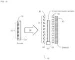
- FIG. 1Cschematically illustrates an example system comprising at least one mask in accordance with certain implementations described herein.
- FIGS. 2A-2Cshow an absorption image, a differential phase contrast image, and a dark-field image, respectively, of a portion of a semiconductor sample comprising a plurality of microbumps under inspection in accordance with certain implementations described herein.
- X-ray dark-field contrastis of interest because it is particularly sensitive to features (e.g., voids; cracks) with dimensions at the micron to submicron scale.
- X-ray dark-field contrastis fundamentally different than absorption contrast, which forms the basis of current x-ray imaging techniques and instead is based on measuring small angle x-ray scattering (SAXS).
- SAXSsmall angle x-ray scattering
- Talbot-Lau interferometryis another inspection technique that simultaneously acquires absorption, phase, and dark-field contrasts using grating-based interferometry.
- a standard Talbot-Lau interferometeruses a large extended x-ray source coupled to a G 0 grating (e.g., source grating) having a 1:2 or 1:3 duty cycle, such that more than half of the x-rays produced by the x-ray source are absorbed by the absorptive struts of the G 0 grating.
- the G 0 gratingeffectively creates a linear or 2D array of periodic sub-sources of x-rays from the x-ray source that are transmitted through the G 0 grating.
- a G 1 grating(e.g., beam-splitting grating), which can be either an absorbing grating or a phase shifting grating, can be positioned downstream from the G 0 grating to diffract the x-rays such that a Talbot carpet of x-rays is formed which irradiates the sample being inspected.
- a G 2 grating(e.g., detector grating) can be typically positioned in front of (e.g., upstream from) a large pixel x-ray detector configured to detect the fringes of x-rays from the sample being inspected to determine absorption, phase, and dark-field (e.g., scattering) contrasts.
- Talbot-Lau interferometryutilizes configurations that satisfy at least the following two conditions:
- Talbot-Lau interferometryutilizes phase-stepping (e.g., relative motion of the G 1 grating and the G 2 grating) so that the Talbot fringes can be sampled multiple times (e.g., at least three times if not more), and the time needed for such phase-stepping can adversely increase the overall time of the inspection.
- the absorption and phase contrast of Talbot-Lau interferometryare not necessary for defect detection and inspection.
- the Talbot conditionsets a minimum to the distance d G0-G1 between the G 0 grating and the G 1 grating, which can limit throughput.
- Certain implementations described hereinadvantageously provide a dark-field-only inspection (e.g., imaging) system for semiconductor samples (e.g., a system that does not utilize absorption or phase contrast). Certain implementations described herein satisfy only the Lau condition (e.g., do not satisfy the Talbot condition). Certain implementations described herein utilize at least first and second absorption gratings in a magnifying arrangement (e.g., as in a projection microscope) in which the second absorption grating blocks x-rays passed by the first absorption grating in the absence of a sample from reaching the x-ray detector.
- Small angle scattering(e.g., due to edges and/or interfaces within the sample) provide x-rays that pass through the openings of the second absorption grating to be detected by an area x-ray detector positioned downstream from the second absorption grating.
- the sampleis positioned between the first and second absorption gratings.
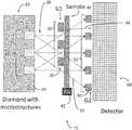
- FIGS. 1A and 1Bschematically illustrate an example system 10 that utilizes only dark-field contrast and satisfies only the Lau condition in accordance with certain implementations described herein.
- the example system 10comprises an x-ray source 20 comprising a plurality of sub-sources 22 (e.g., one or more arrays of metal microstructures) in thermal communication with a substrate 24 (e.g., embedded or on a diamond substrate) and that are configured to emit x-rays 26 when bombarded by electrons (not shown).
- a substrate 24e.g., embedded or on a diamond substrate
- Examples of x-ray sources 20 with a plurality of sub-sources 22 compatible with certain implementations described hereinare disclosed (in conjunction with other systems different from those described herein) in U.S. Pat. Nos.
- Such x-ray sources 20do not utilize a G 0 grating (e.g., source grating), which is different from conventional sources that combine a G 0 grating with an extended x-ray source.
- G 0 gratinge.g., source grating
- the example system 10further comprises a first grating 30 (e.g., “G 1 grating”) positioned to receive at least some of the x-rays 26 from the x-ray source 20 (e.g., positioned downstream from the x-ray source 20 ), the first grating 30 comprising periodic structures configured to absorb at least some of the x-rays 26 received from the x-ray source 20 .
- the first grating 30comprises an array of x-ray absorptive structures 32 that is periodic in a single dimension (e.g. lines of x-ray absorptive material).
- the first grating 30comprises an array of x-ray absorptive structures 32 that is periodic in two dimensions (e.g., checkerboard, honeycomb, mesh, or grid of x-ray absorptive material).
- a first grating 30e.g., “G 1 grating”
- Examples of a first grating 30 with periodic structures 32 compatible with certain implementations described hereinare disclosed (in conjunction with other systems different from those described herein) in U.S. Pat. Nos. 9,719,947; 9,874,531; 10,304,580; 10,349,908; 10,352,880, each of which is incorporated in its entirety by reference herein.
- the example system 10further comprises a stage 42 configured to hold a sample 40 , the sample 40 positioned to receive at least some of the x-rays 26 from the x-ray source 20 (e.g., positioned downstream from the x-ray source 20 ).
- the sample 40is configured to scatter and emit a first portion 44 of the x-rays 26 and to emit without scattering (e.g., transmit) a second portion 46 of the x-rays 26 .
- Examples of a stage 42 compatible with certain implementations described hereinare disclosed (in conjunction with other systems different from those described herein) in U.S. Pat. Nos. 9,719,947; 9,874,531; 10,349,908; 10,352,880, each of which is incorporated in its entirety by reference herein.
- the example system 10further comprises a second grating 50 (e.g., “G 2 grating” or “G D grating”) positioned to receive at least some of the first portion 44 of the x-rays 26 and at least some of the second portion 46 of the x-rays 26 (e.g., downstream from the sample 40 ).
- the example system 10further comprises at least one x-ray detector 60 positioned to receive at least some of the first portion 44 of the x-rays from the second grating 50 (e.g., positioned downstream from the second grating 50 ).
- the at least one detector 60can comprise a spatially resolving detector (e.g., CCD or linear sensitivity detector).
- the at least one detector 60can comprise a non-spatially resolving detector that simply measures the amount of scattered x-rays and is configured to monitor only changes in the dark-field scattered signal as an inspection technique.
- detectors 60compatible with certain implementations described herein are disclosed (in conjunction with other systems different from those described herein) in U.S. Pat. Nos. 9,719,947; 9,874,531; 10,349,908; 10,352,880, each of which is incorporated in its entirety by reference herein.
- the second grating 50comprises periodic structures configured to substantially block transmission of the second portion 46 of the x-rays 26 from reaching the at least one x-ray detector 60 while substantially allowing transmission of the first portion 44 of the x-rays 26 to the at least one x-ray detector 60 .
- the second grating 50comprises an array of x-ray absorptive structures 52 that is periodic in a single dimension (e.g. lines of x-ray absorptive material).
- the second grating 50comprises an array of x-ray absorptive structures 52 that is periodic in two dimensions (e.g., checkerboard, honeycomb, mesh, or grid of x-ray absorptive material).
- Examples of a second grating 50e.g., “G 2 grating” or “G D grating”
- G 2 gratingor “G D grating”
- periodic structures 32compatible with certain implementations described herein are disclosed (in conjunction with other systems different from those described herein) in U.S. Pat. Nos. 9,719,947; 9,874,531; 10,304,580; 10,349,908; 10,352,880, each of which is incorporated in its entirety by reference herein.
- the second grating 50 of certain implementationsis positioned such that x-rays 26 that directly propagate from the x-ray source 20 and that are collimated by the first grating 30 are substantially blocked by the second grating 50 from reaching the at least one x-ray detector 60 , while scattered x-rays 26 are not substantially blocked by the second grating 50 from reaching the at least one x-ray detector 60 .
- the sample 40is positioned behind (e.g., downstream from) the first grating 30 such that the sample 40 receives at least some of the x-rays 26 from (e.g., transmitted through) the first grating 30 and the second grating 50 is positioned behind (e.g., downstream from) the sample 40 to receive at least some of the first portion 44 of the x-rays 26 from the sample 40 and at least some of the second portion 46 of the x-rays 26 from the sample 40 (e.g., positioned downstream from the sample 40 ).
- Certain such implementationscan be advantageous by protecting the sample 40 from being exposed to an unnecessary dose of x-rays.
- the distance between the first grating 30 and the sample 40 and the distance between the second grating 50 and the at least one x-ray detector 60are selected to be as small as practical as other operative constraints (e.g., compatibility for use in inspection of samples 40 while on a production/fabrication line) will allow.
- the distance between the first grating 30 and the sample 40can be less than 10 mm.
- the distance between the second grating 50 and the at least one x-ray detector 60is selected to minimize the overall length of the system 10 (e.g., to provide a more compact form factor).
- Sensitivity to larger voidscan be increased in certain implementations by using larger distances between the sample 40 and the at least one x-ray detector 60 , since the minimum angle of small angle x-ray detection is directly proportional to the opening width of the second grating 50 divided by the distance between the first grating 30 and the second grating 50 .
- certain implementationslimit the geometric magnification.
- the geometric magnification of the sample 40can be in the range of four to six and can be configured to improve sensitivity to larger voids (which have smaller scattering) and to use larger pixel sizes.
- the x-ray source 20 , the first grating 30 , and the second grating 50are further configured to not satisfy the Talbot condition, such that a ratio of a distance d S-G1 between the x-ray source 20 and the first grating 30 and a spacing w 0 between adjacent sub-sources 22 of the plurality of sub-sources 22 is greater than a pitch p 1 of the first grating 30 divided by a wavelength ⁇ of the x-rays 26 : (d S-G1 /w 0 )>(p 1 / ⁇ ).
- the x-ray source 20 , the first grating 30 , and the second grating 50are further configured such that the distance between the first grating 30 and the sample 40 is small to maximize throughput (e.g., d S-G1 is in a range of less than 3 mm or in a range of less than 50 mm).
- the system 10comprises at least one mask 70 positioned in front of (e.g., upstream from) the sample 40 .
- the at least one mask 70comprises x-ray absorptive portions 72 (e.g., x-ray absorptive material) and x-ray transmissive portions 74 (e.g., openings), the x-ray transmissive portions 74 corresponding to (e.g., in registry with) the features of the sample 40 (e.g., vias; microbumps) under inspection.
- certain implementations utilizing the at least one mask 70advantageously reduce the background x-ray signal received by the at least one x-ray detector 60 .
- Certain implementations utilizing the at least one mask 70can advantageously improve image resolution by reducing (e.g., avoiding) photoelectron creation in regions of the x-ray detector 60 that do not correspond to the features under inspection and having these photoelectrons “bleed through” to the regions that do correspond to the features under inspection, with such photoelectrons reducing image resolution by contributing to the blurriness of the images.
- Certain implementations utilizing the at least one mask 70advantageously protect the sample 40 from unnecessary x-ray dosage which could otherwise cause damage to the sample 40 .
- the x-ray source 20can be configured to be controllably moved (e.g., in a direction parallel to a surface of the substrate 24 ) such that different regions of the at least one x-ray detector 60 receive the scattered x-rays (e.g., making use of parallax).
- the x-ray detector 60is not an imaging detector but is configured to provide information regarding the scattered x-rays corresponding to the features under inspection.
- the x-ray source 20 , the first and second gratings 30 , 50 , and the at least one mask 70can be configured to be controllably moved along with the moving sample 40 to maintain the desired configuration. Alignment of the various components can be assured by using appropriate fiducials and servo-controlled alignment aids.
- the sample 40is rotated to acquire three-dimensional dark-field images.
- the x-ray source 20comprises a plurality of sub-sources 22 that comprise microstructures that comprise tungsten, rhodium, molybdenum, or other high-Z elements.
- the microstructurescomprise a diffusion barrier between the microstructures and the substrate 24 (e.g., diamond).
- the x-rays 26 generated by the x-ray source 20have a mean x-ray energy in a range of 20 keV to 30 keV, in a range of 30 keV to 50 keV, or in a range of 50 keV to 80 keV.
- the x-ray source 20 of certain implementationscan comprise a filter configured to remove x-rays having energies below a predetermined value.
- the substrate 24is on a window (e.g., diamond window; beryllium window) at least partially bounding a vacuum region within the x-ray source 20 from a non-vacuum region outside the x-ray source 20 .
- the substrate 24is within an x-ray tube in a reflection geometry with the window (e.g., diamond window; beryllium window).
- the sub-sources 22have a size (e.g., lateral dimension along a direction parallel to a surface of the substrate 24 ) in a range of 0.3 micron to 1 micron, in a range of 1 micron to 3 microns, or in a range of 3 microns to 10 microns.
- the pitch p 0is in a range that is comparable to the range of sizes of the sub-sources 22 (e.g., the pitch p 0 is in a range of 0.3 micron to 1 micron, in a range of 1 micron to 3 microns, or in a range of 3 microns to 10 microns).
- a ratio of the size of the sub-sources 22 to the size of the space between adjacent sub-sources 22is in a range of 1:1 to 1:2 or in a range of 1:2 to 1:3 (e.g., the ratio can be substantially equal to 1:3).
- the pitch p 1 for the first grating 30(e.g., distance from a position on a first x-ray absorptive structure 32 a to the equivalent position on a second x-ray absorptive structure 32 b adjacent to the first x-ray absorptive structures 32 a ) can be in a range of 0.3 micron to 1 micron, in a range of 1 micron to 3 microns, in a range of 3 microns to 10 microns, or in a range of 10 microns to 50 microns.
- the x-ray absorptive structures 32 of the first grating 30are configured to block the spaces between adjacent x-ray absorptive structures 52 of the second grating 50 in a projection geometry.
- the first grating 30has a first ratio of open to blocked areas and the second grating 50 has a second ratio of open to blocked areas that is larger than or equal to the first ratio (e.g., the first ratio equal to 1:1 and the second ratio in a range of 1:1 to 1:0.9 or in a range of 1:1 to 1:0.7).
- the pitch p 2 for the second grating 50(e.g., distance from a position on a first x-ray absorptive structure 52 a to the equivalent position on a second x-ray absorptive structure 52 b adjacent to the first x-ray absorptive structures 52 a ) can be in a range of 1 micron to 10 microns, in a range of 10 microns to 40 microns, in a range of 40 microns to 60 microns, in a range of 60 microns to 80 microns, or in a range of 80 microns to 200 microns.
- the pitch p 2is substantially equal to the pitch p 1 multiplied by (d S-G2 /d S-G1 ), where d S-G2 is the distance between the sub-sources 22 and the second grating 50 and d S-G1 is the distance between the sub-sources 22 and the first grating 30 .
- the distance d S-G1 between the sub-sources 22 of the x-ray source 20 and the first grating 30is in a range of 2 mm to 4 mm, in a range of 4 mm to 10 mm, in a range of 10 mm to 30 mm, in a range of 30 mm to 100 mm, or in a range of 100 mm to 500 mm.
- the distance d G1-G2 between the first grating 30 and the second grating 50is in a range of 30 mm to 100 mm, in a range of 100 mm to 500 mm, or in a range of 500 mm to 1500 mm.
- the system 10is configured to be used for inspection for defects in semiconductor packaging or other two-dimensional samples (e.g., as the samples are processed along the production line).
- the system 10is configured for dark-field imaging for medical use (e.g., clinical medical 2D x-ray).
- the system 10is configured to be used for laminography (e.g., 2.5D) in addition to 2D, or for dark-field tomography acquisition, or for three-dimensional imaging.
- the sample 40can be placed on a conveyer belt such that a seconds-long dark-field image is obtained while the sample 40 is moving.
- the sample 40can be placed in front of the first grating 30 (which is placed near the second grating 50 and the at least one x-ray detector 60 ) such that large samples 40 can be rotated.
- the distance between the first grating 30 and the second grating 50can be small and the overall size of the system 10 can be compact.
- FIGS. 2A-2Cshow an absorption image, a differential phase contrast image, and a dark-field image, respectively, of a portion of a semiconductor sample comprising a plurality of microbumps under inspection in accordance with certain implementations described herein.
- the dark-field image of FIG. 1Cshows regions (e.g., “white spots”) at the centers of the microbumps that are indicative of voids.
- the dark-field images of certain implementationscan show cracks and other features (e.g., substrate defects) that are not seen in conventional absorption imaging.
- the terms “generally parallel” and “substantially parallel”refer to a value, amount, or characteristic that departs from exactly parallel by ⁇ 10 degrees, by ⁇ 5 degrees, by ⁇ 2 degrees, by ⁇ 1 degree, or by ⁇ 0.1 degree
- the terms “generally perpendicular” and “substantially perpendicular”refer to a value, amount, or characteristic that departs from exactly perpendicular by ⁇ 10 degrees, by ⁇ 5 degrees, by ⁇ 2 degrees, by ⁇ 1 degree, or by ⁇ 0.1 degree.
- the ranges disclosed hereinalso encompass any and all overlap, sub-ranges, and combinations thereof. Language such as “up to,” “at least,” “greater than,” less than,” “between,” and the like includes the number recited.
Landscapes
- Health & Medical Sciences (AREA)
- Analytical Chemistry (AREA)
- Physics & Mathematics (AREA)
- Life Sciences & Earth Sciences (AREA)
- Chemical & Material Sciences (AREA)
- Biochemistry (AREA)
- General Health & Medical Sciences (AREA)
- General Physics & Mathematics (AREA)
- Immunology (AREA)
- Pathology (AREA)
- Toxicology (AREA)
- Radiology & Medical Imaging (AREA)
- Nuclear Medicine, Radiotherapy & Molecular Imaging (AREA)
- Analysing Materials By The Use Of Radiation (AREA)
Abstract
Description
This application claims the benefit of priority to U.S. Provisional Appl. No. 62/971,062 filed on Feb. 6, 2020 and incorporated in its entirety by reference herein.
The present application relates generally to x-ray imaging/inspection systems.
Advanced packaging in modern electronics includes microbumps and through silicon vias (TSVs) that join various integrated circuits (ICs) together in “2.5 dimensional” and/or “3 dimensional” packaging schemes. These features have been continuously scaled to smaller dimensions and have been altered to different materials. For example, lead solder bumps (e.g., with dimensions on the order of hundreds of microns) have now been replaced by microbumps (e.g., with dimensions of about 20-40 microns) that typically comprise a copper pillar and a silver/tin top layer above the copper pillar, with a thin nickel layer between the silver/tin top layer and the copper pillar.
Shrinking dimensions can result in less tolerance for defects, such as voids, in these features. In particular, the autonomous (e.g., self-driving) vehicle market demands zero tolerance for defects and 100% inspection. Such inspection is generally performed using x-rays, which have sufficient penetration and are also non-destructive, thereby enabling validation of every single packaging component. Additional failure mechanisms, such as silicon die cracks and delamination, are also of significant interest to the semiconductor field.
In certain implementations, an x-ray imaging/inspection system is provided. The system comprises an x-ray source comprising a plurality of sub-sources in thermal communication with a substrate and that are configured to emit x-rays when bombarded by electrons configured to generate x-rays by electron bombardment of the target material. The system further comprises a first grating positioned to receive at least some of the x-rays from the x-ray source. The first grating comprises periodic structures configured to absorb at least some of the x-rays received from the x-ray source. The system further comprises a stage configured to hold a sample positioned to receive at least some of the x-rays from the x-ray source. The sample is configured to scatter and emit a first portion of the x-rays and to emit without scattering a second portion of the x-rays. The system further comprises at least one x-ray detector. The system further comprises a second grating positioned to receive at least some of the first portion of the x-rays and at least some of the second portion of the x-rays. The second grating comprises periodic structures configured to substantially block transmission of the second portion of the x-rays from reaching the at least one x-ray detector while substantially allowing transmission of the first portion of the x-rays to the at least one x-ray detector. The x-ray source, the first grating, and the second grating are configured such that a ratio of a pitch p0of the plurality of sub-sources to a pitch p2of the periodic structures of the second grating is substantially equal to a ratio of a distance dS-G1between the plurality of sub-sources and the first grating and a distance dG1-G2between the first grating and the second grating: (p0/p2)=(dS-G1/dG1-G2).
Current inspection techniques center around analyzing the x-ray absorption across a two-dimensional (2D) region of the sample. However, the sensitivity of such techniques to voids decreases rapidly for smaller voids because the x-ray absorption by a sample region comprising such smaller voids is only slightly less than the absorption by a sample region without such smaller voids. Three-dimensional (3D) x-ray inspection schemes have been posited, but they are too slow for 100% inspection and they increase the radiation dose applied to the sample, which can be problematic for NAND flash memory by introducing defects caused by the increased radiation. Some inspection schemes use laminography (a “2.5 dimensional” technique), which offers some improvements in sensitivity.
X-ray dark-field (e.g., x-ray scattering) contrast is of interest because it is particularly sensitive to features (e.g., voids; cracks) with dimensions at the micron to submicron scale. X-ray dark-field contrast is fundamentally different than absorption contrast, which forms the basis of current x-ray imaging techniques and instead is based on measuring small angle x-ray scattering (SAXS). However, conventional SAXS is typically performed with systems that utilize long flight paths for collimation and that are not ideal for in-line semiconductor use.
Talbot-Lau interferometry is another inspection technique that simultaneously acquires absorption, phase, and dark-field contrasts using grating-based interferometry. A standard Talbot-Lau interferometer uses a large extended x-ray source coupled to a G0grating (e.g., source grating) having a 1:2 or 1:3 duty cycle, such that more than half of the x-rays produced by the x-ray source are absorbed by the absorptive struts of the G0grating. The G0grating effectively creates a linear or 2D array of periodic sub-sources of x-rays from the x-ray source that are transmitted through the G0grating. A G1grating (e.g., beam-splitting grating), which can be either an absorbing grating or a phase shifting grating, can be positioned downstream from the G0grating to diffract the x-rays such that a Talbot carpet of x-rays is formed which irradiates the sample being inspected. A G2grating (e.g., detector grating) can be typically positioned in front of (e.g., upstream from) a large pixel x-ray detector configured to detect the fringes of x-rays from the sample being inspected to determine absorption, phase, and dark-field (e.g., scattering) contrasts.
Talbot-Lau interferometry utilizes configurations that satisfy at least the following two conditions:
- 1. Talbot (coherence) condition to form fringes: Coherence is related to the width (w0) of openings of the G0grating divided by the distance dG0-G1between the G0grating and the G1grating. Under the Talbot (coherence) condition, this quantity is smaller than the pitch p1of the G1grating divided by the wavelength λ of the x-ray energy: (dG0-G1×λ)/w0≅p1.
- 2. Lau condition: A geometric relation in which the ratio of the pitch (p0) of the G0grating to the pitch p2of the G2grating is equivalent to the ratio of the distance dG0-G1between the G0grating and the G1grating and the distance dG1-G2between the G1grating and the G2grating: (p0/p2)=(dG0-G1/dG1-G2). When the Lau condition is satisfied, the Talbot fringes downstream of the G1grating from an opening (e.g., micron-sized sub-source) of the G0grating is shifted by exactly one period, and from the nth neighbor opening of the G0grating is shifted by n number of periods. Therefore, the Talbot fringes from all the openings of the G0grating completely overlap, which is an important innovation, attributed to Lau, that enables the use of large extended x-ray sources with a G0grating.
However, Talbot-Lau interferometry utilizes phase-stepping (e.g., relative motion of the G1grating and the G2grating) so that the Talbot fringes can be sampled multiple times (e.g., at least three times if not more), and the time needed for such phase-stepping can adversely increase the overall time of the inspection. In addition, the absorption and phase contrast of Talbot-Lau interferometry are not necessary for defect detection and inspection. Furthermore, the Talbot condition sets a minimum to the distance dG0-G1between the G0grating and the G1grating, which can limit throughput.
Certain implementations described herein advantageously provide a dark-field-only inspection (e.g., imaging) system for semiconductor samples (e.g., a system that does not utilize absorption or phase contrast). Certain implementations described herein satisfy only the Lau condition (e.g., do not satisfy the Talbot condition). Certain implementations described herein utilize at least first and second absorption gratings in a magnifying arrangement (e.g., as in a projection microscope) in which the second absorption grating blocks x-rays passed by the first absorption grating in the absence of a sample from reaching the x-ray detector. Small angle scattering (e.g., due to edges and/or interfaces within the sample) provide x-rays that pass through the openings of the second absorption grating to be detected by an area x-ray detector positioned downstream from the second absorption grating. In certain implementations, the sample is positioned between the first and second absorption gratings.
Theexample system 10 further comprises a first grating30 (e.g., “G1grating”) positioned to receive at least some of thex-rays 26 from the x-ray source20 (e.g., positioned downstream from the x-ray source20), thefirst grating 30 comprising periodic structures configured to absorb at least some of thex-rays 26 received from thex-ray source 20. For example, thefirst grating 30 comprises an array of x-rayabsorptive structures 32 that is periodic in a single dimension (e.g. lines of x-ray absorptive material). For another example, thefirst grating 30 comprises an array of x-rayabsorptive structures 32 that is periodic in two dimensions (e.g., checkerboard, honeycomb, mesh, or grid of x-ray absorptive material). Examples of a first grating30 (e.g., “G1grating”) withperiodic structures 32 compatible with certain implementations described herein are disclosed (in conjunction with other systems different from those described herein) in U.S. Pat. Nos. 9,719,947; 9,874,531; 10,304,580; 10,349,908; 10,352,880, each of which is incorporated in its entirety by reference herein.
Theexample system 10 further comprises astage 42 configured to hold asample 40, thesample 40 positioned to receive at least some of thex-rays 26 from the x-ray source20 (e.g., positioned downstream from the x-ray source20). Thesample 40 is configured to scatter and emit afirst portion 44 of thex-rays 26 and to emit without scattering (e.g., transmit) asecond portion 46 of thex-rays 26. Examples of astage 42 compatible with certain implementations described herein are disclosed (in conjunction with other systems different from those described herein) in U.S. Pat. Nos. 9,719,947; 9,874,531; 10,349,908; 10,352,880, each of which is incorporated in its entirety by reference herein.
Theexample system 10 further comprises a second grating50 (e.g., “G2grating” or “GDgrating”) positioned to receive at least some of thefirst portion 44 of thex-rays 26 and at least some of thesecond portion 46 of the x-rays26 (e.g., downstream from the sample40). Theexample system 10 further comprises at least onex-ray detector 60 positioned to receive at least some of thefirst portion 44 of the x-rays from the second grating50 (e.g., positioned downstream from the second grating50). For example, the at least onedetector 60 can comprise a spatially resolving detector (e.g., CCD or linear sensitivity detector). For another example, the at least onedetector 60 can comprise a non-spatially resolving detector that simply measures the amount of scattered x-rays and is configured to monitor only changes in the dark-field scattered signal as an inspection technique. Examples ofdetectors 60 compatible with certain implementations described herein are disclosed (in conjunction with other systems different from those described herein) in U.S. Pat. Nos. 9,719,947; 9,874,531; 10,349,908; 10,352,880, each of which is incorporated in its entirety by reference herein.
As schematically illustrated byFIG. 1B , thesecond grating 50 comprises periodic structures configured to substantially block transmission of thesecond portion 46 of thex-rays 26 from reaching the at least onex-ray detector 60 while substantially allowing transmission of thefirst portion 44 of thex-rays 26 to the at least onex-ray detector 60. For example, thesecond grating 50 comprises an array of x-rayabsorptive structures 52 that is periodic in a single dimension (e.g. lines of x-ray absorptive material). For another example, thesecond grating 50 comprises an array of x-rayabsorptive structures 52 that is periodic in two dimensions (e.g., checkerboard, honeycomb, mesh, or grid of x-ray absorptive material). Examples of a second grating50 (e.g., “G2grating” or “GDgrating”) withperiodic structures 32 compatible with certain implementations described herein are disclosed (in conjunction with other systems different from those described herein) in U.S. Pat. Nos. 9,719,947; 9,874,531; 10,304,580; 10,349,908; 10,352,880, each of which is incorporated in its entirety by reference herein.
In certain implementations, theexample system 10 is configured to meet the Lau condition in which the ratio of the pitch p0of the plurality ofsub-sources 22 to the pitch p2of the array of x-rayabsorptive structures 52 of the second grating50 (e.g., G2grating) is substantially equal to the ratio of the distance dS-G1between the plurality ofsub-sources 22 of thex-ray source 20 and the first grating30 (e.g., G1grating) and the distance dG1-G2between the first grating30 (e.g., G1grating) and the second grating50 (e.g., G2grating): (p0/p2)=(dS-G1/dG1-G2). In addition, thesecond grating 50 of certain implementations is positioned such thatx-rays 26 that directly propagate from thex-ray source 20 and that are collimated by thefirst grating 30 are substantially blocked by thesecond grating 50 from reaching the at least onex-ray detector 60, whilescattered x-rays 26 are not substantially blocked by thesecond grating 50 from reaching the at least onex-ray detector 60.
In certain other implementations, as schematically illustrated byFIGS. 1A and 1B , thesample 40 is positioned behind (e.g., downstream from) thefirst grating 30 such that thesample 40 receives at least some of thex-rays 26 from (e.g., transmitted through) thefirst grating 30 and thesecond grating 50 is positioned behind (e.g., downstream from) thesample 40 to receive at least some of thefirst portion 44 of thex-rays 26 from thesample 40 and at least some of thesecond portion 46 of thex-rays 26 from the sample40 (e.g., positioned downstream from the sample40). Certain such implementations can be advantageous by protecting thesample 40 from being exposed to an unnecessary dose of x-rays. In certain implementations, the distance between thefirst grating 30 and thesample 40 and the distance between thesecond grating 50 and the at least onex-ray detector 60 are selected to be as small as practical as other operative constraints (e.g., compatibility for use in inspection ofsamples 40 while on a production/fabrication line) will allow. For example, for two-dimensional imaging, the distance between thefirst grating 30 and thesample 40 can be less than 10 mm. In certain implementations, the distance between thesecond grating 50 and the at least onex-ray detector 60 is selected to minimize the overall length of the system10 (e.g., to provide a more compact form factor).
Sensitivity to larger voids can be increased in certain implementations by using larger distances between thesample 40 and the at least onex-ray detector 60, since the minimum angle of small angle x-ray detection is directly proportional to the opening width of thesecond grating 50 divided by the distance between thefirst grating 30 and thesecond grating 50. However, since increasing geometric magnification can reduce sensitivity due to smearing and can result in larger form factors, certain implementations limit the geometric magnification. For example, the geometric magnification of thesample 40 can be in the range of four to six and can be configured to improve sensitivity to larger voids (which have smaller scattering) and to use larger pixel sizes.
In certain implementations, thex-ray source 20, thefirst grating 30, and thesecond grating 50 are configured to satisfy the Lau condition, such that a ratio of a pitch p0of the plurality ofsub-sources 22 to a pitch p2of theperiodic structures 52 of thesecond grating 50 is substantially equal to a ratio of a distance dS-G1between the plurality ofsub-sources 22 and thefirst grating 30 and a distance dG1-G2between thefirst grating 30 and the second grating50: (p0/p2)=(dS-G1/dG1-G2). In certain such implementations, thex-ray source 20, thefirst grating 30, and thesecond grating 50 are further configured to not satisfy the Talbot condition, such that a ratio of a distance dS-G1between thex-ray source 20 and thefirst grating 30 and a spacing w0betweenadjacent sub-sources 22 of the plurality of sub-sources22 is greater than a pitch p1of thefirst grating 30 divided by a wavelength λ of the x-rays26: (dS-G1/w0)>(p1/λ). In certain implementations, thex-ray source 20, thefirst grating 30, and thesecond grating 50 are further configured such that the distance between thefirst grating 30 and thesample 40 is small to maximize throughput (e.g., dS-G1is in a range of less than 3 mm or in a range of less than 50 mm).
In certain implementations, as schematically illustrated byFIG. 1C , thesystem 10 comprises at least onemask 70 positioned in front of (e.g., upstream from) thesample 40. The at least onemask 70 comprises x-ray absorptive portions72 (e.g., x-ray absorptive material) and x-ray transmissive portions74 (e.g., openings), thex-ray transmissive portions 74 corresponding to (e.g., in registry with) the features of the sample40 (e.g., vias; microbumps) under inspection. By substantially preventing x-rays from irradiating portions of thesample 40 between the features under inspection, and which would otherwise not contribute useful signal but would add to the radiation dosage received by thesample 40, certain implementations utilizing the at least onemask 70 advantageously reduce the background x-ray signal received by the at least onex-ray detector 60. Certain implementations utilizing the at least onemask 70 can advantageously improve image resolution by reducing (e.g., avoiding) photoelectron creation in regions of thex-ray detector 60 that do not correspond to the features under inspection and having these photoelectrons “bleed through” to the regions that do correspond to the features under inspection, with such photoelectrons reducing image resolution by contributing to the blurriness of the images. Certain implementations utilizing the at least onemask 70 advantageously protect thesample 40 from unnecessary x-ray dosage which could otherwise cause damage to thesample 40.
In certain implementations, only a relatively small fraction of the area of the at least onex-ray detector 60 receives scattered x-rays that are transmitted through thesecond grating 50. In certain such implementations, thex-ray source 20 can be configured to be controllably moved (e.g., in a direction parallel to a surface of the substrate24) such that different regions of the at least onex-ray detector 60 receive the scattered x-rays (e.g., making use of parallax). In certain implementations, thex-ray detector 60 is not an imaging detector but is configured to provide information regarding the scattered x-rays corresponding to the features under inspection.
In certain implementations in which thesample 40 is moving during the inspection process (e.g., while thesample 40 travels along a production line), thex-ray source 20, the first andsecond gratings systems 10 comprising at least one mask70) can be configured to be controllably moved along with the movingsample 40 to maintain the desired configuration. Alignment of the various components can be assured by using appropriate fiducials and servo-controlled alignment aids. In certain implementations, thesample 40 is rotated to acquire three-dimensional dark-field images.
Parameters of Example Implementations
In certain implementations, thex-ray source 20 comprises a plurality ofsub-sources 22 that comprise microstructures that comprise tungsten, rhodium, molybdenum, or other high-Z elements. In certain implementations, the microstructures comprise a diffusion barrier between the microstructures and the substrate24 (e.g., diamond).
In certain implementations, thex-rays 26 generated by thex-ray source 20 have a mean x-ray energy in a range of 20 keV to 30 keV, in a range of 30 keV to 50 keV, or in a range of 50 keV to 80 keV. Thex-ray source 20 of certain implementations can comprise a filter configured to remove x-rays having energies below a predetermined value. In certain implementations, thesubstrate 24 is on a window (e.g., diamond window; beryllium window) at least partially bounding a vacuum region within thex-ray source 20 from a non-vacuum region outside thex-ray source 20. In certain other implementations, thesubstrate 24 is within an x-ray tube in a reflection geometry with the window (e.g., diamond window; beryllium window).
In certain implementations, the sub-sources22 have a size (e.g., lateral dimension along a direction parallel to a surface of the substrate24) in a range of 0.3 micron to 1 micron, in a range of 1 micron to 3 microns, or in a range of 3 microns to 10 microns. In certain implementations, the pitch p0is in a range that is comparable to the range of sizes of the sub-sources22 (e.g., the pitch p0is in a range of 0.3 micron to 1 micron, in a range of 1 micron to 3 microns, or in a range of 3 microns to 10 microns). In certain implementations, a ratio of the size of the sub-sources22 to the size of the space between adjacent sub-sources22 is in a range of 1:1 to 1:2 or in a range of 1:2 to 1:3 (e.g., the ratio can be substantially equal to 1:3).
In certain implementations, the pitch p1for the first grating30 (e.g., distance from a position on a first x-ray absorptive structure32ato the equivalent position on a second x-ray absorptive structure32badjacent to the first x-ray absorptive structures32a) can be in a range of 0.3 micron to 1 micron, in a range of 1 micron to 3 microns, in a range of 3 microns to 10 microns, or in a range of 10 microns to 50 microns. In certain implementations, the x-rayabsorptive structures 32 of thefirst grating 30 are configured to block the spaces between adjacent x-rayabsorptive structures 52 of thesecond grating 50 in a projection geometry. In certain such implementations, thefirst grating 30 has a first ratio of open to blocked areas and thesecond grating 50 has a second ratio of open to blocked areas that is larger than or equal to the first ratio (e.g., the first ratio equal to 1:1 and the second ratio in a range of 1:1 to 1:0.9 or in a range of 1:1 to 1:0.7). In certain implementations, the pitch p2for the second grating50 (e.g., distance from a position on a first x-ray absorptive structure52ato the equivalent position on a second x-ray absorptive structure52badjacent to the first x-ray absorptive structures52a) can be in a range of 1 micron to 10 microns, in a range of 10 microns to 40 microns, in a range of 40 microns to 60 microns, in a range of 60 microns to 80 microns, or in a range of 80 microns to 200 microns. In certain implementations, the pitch p2is substantially equal to the pitch p1multiplied by (dS-G2/dS-G1), where dS-G2is the distance between the sub-sources22 and thesecond grating 50 and dS-G1is the distance between the sub-sources22 and thefirst grating 30.
In certain implementations, the distance dS-G1between the sub-sources22 of thex-ray source 20 and thefirst grating 30 is in a range of 2 mm to 4 mm, in a range of 4 mm to 10 mm, in a range of 10 mm to 30 mm, in a range of 30 mm to 100 mm, or in a range of 100 mm to 500 mm. In certain implementations, the distance dG1-G2between thefirst grating 30 and thesecond grating 50 is in a range of 30 mm to 100 mm, in a range of 100 mm to 500 mm, or in a range of 500 mm to 1500 mm.
In certain implementations, thesystem 10 is configured to be used for inspection for defects in semiconductor packaging or other two-dimensional samples (e.g., as the samples are processed along the production line). In certain implementations, thesystem 10 is configured for dark-field imaging for medical use (e.g., clinical medical 2D x-ray). In certain implementations, thesystem 10 is configured to be used for laminography (e.g., 2.5D) in addition to 2D, or for dark-field tomography acquisition, or for three-dimensional imaging. For in-line semiconductor imaging implementations, thesample 40 can be placed on a conveyer belt such that a seconds-long dark-field image is obtained while thesample 40 is moving. For three-dimensional or laminography imaging implementations, thesample 40 can be placed in front of the first grating30 (which is placed near thesecond grating 50 and the at least one x-ray detector60) such thatlarge samples 40 can be rotated. In certain implementations in which only small voids are of interest, the distance between thefirst grating 30 and thesecond grating 50 can be small and the overall size of thesystem 10 can be compact.
Although commonly used terms are used to describe the systems and methods of certain implementations for ease of understanding, these terms are used herein to have their broadest reasonable interpretations. Although various aspects of the disclosure are described with regard to illustrative examples and implementations, the disclosed examples and implementations should not be construed as limiting. Conditional language, such as “can,” “could,” “might,” or “may,” unless specifically stated otherwise, or otherwise understood within the context as used, is generally intended to convey that certain implementations include, while other implementations do not include, certain features, elements, and/or steps. Thus, such conditional language is not generally intended to imply that features, elements, and/or steps are in any way required for one or more implementations. In particular, the terms “comprises” and “comprising” should be interpreted as referring to elements, components, or steps in a non-exclusive manner, indicating that the referenced elements, components, or steps may be present, or utilized, or combined with other elements, components, or steps that are not expressly referenced.
Conjunctive language such as the phrase “at least one of X, Y, and Z,” unless specifically stated otherwise, is to be understood within the context used in general to convey that an item, term, etc. may be either X, Y, or Z. Thus, such conjunctive language is not generally intended to imply that certain implementations require the presence of at least one of X, at least one of Y, and at least one of Z.
Language of degree, as used herein, such as the terms “approximately,” “about,” “generally,” and “substantially,” represent a value, amount, or characteristic close to the stated value, amount, or characteristic that still performs a desired function or achieves a desired result. For example, the terms “approximately,” “about,” “generally,” and “substantially” may refer to an amount that is within ±10% of, within ±5% of, within ±2% of, within ±1% of, or within ±0.1% of the stated amount. As another example, the terms “generally parallel” and “substantially parallel” refer to a value, amount, or characteristic that departs from exactly parallel by ±10 degrees, by ±5 degrees, by ±2 degrees, by ±1 degree, or by ±0.1 degree, and the terms “generally perpendicular” and “substantially perpendicular” refer to a value, amount, or characteristic that departs from exactly perpendicular by ±10 degrees, by ±5 degrees, by ±2 degrees, by ±1 degree, or by ±0.1 degree. The ranges disclosed herein also encompass any and all overlap, sub-ranges, and combinations thereof. Language such as “up to,” “at least,” “greater than,” less than,” “between,” and the like includes the number recited. As used herein, the meaning of “a,” “an,” and “said” includes plural reference unless the context clearly dictates otherwise. While the structures and/or methods are discussed herein in terms of elements labeled by ordinal adjectives (e.g., first, second, etc.), the ordinal adjectives are used merely as labels to distinguish one element from another, and the ordinal adjectives are not used to denote an order of these elements or of their use.
Various configurations have been described above. It is to be appreciated that the implementations disclosed herein are not mutually exclusive and may be combined with one another in various arrangements. Although this invention has been described with reference to these specific configurations, the descriptions are intended to be illustrative of the invention and are not intended to be limiting. Various modifications and applications may occur to those skilled in the art without departing from the true spirit and scope of the invention. Thus, for example, in any method or process disclosed herein, the acts or operations making up the method/process may be performed in any suitable sequence and are not necessarily limited to any particular disclosed sequence. Features or elements from various implementations and examples discussed above may be combined with one another to produce alternative configurations compatible with implementations disclosed herein. Various aspects and advantages of the implementations have been described where appropriate. It is to be understood that not necessarily all such aspects or advantages may be achieved in accordance with any particular implementation. Thus, for example, it should be recognized that the various implementations may be carried out in a manner that achieves or optimizes one advantage or group of advantages as taught herein without necessarily achieving other aspects or advantages as may be taught or suggested herein.
Claims (17)
1. An x-ray imaging/inspection system comprising:
an x-ray source comprising a plurality of sub-sources in thermal communication with a substrate and that are configured to emit x-rays when bombarded by electrons configured to generate x-rays by electron bombardment of the target material;
a first grating positioned to receive at least some of the x-rays from the x-ray source, the first grating comprising periodic structures configured to absorb at least some of the x-rays received from the x-ray source;
a stage configured to hold a sample positioned to receive at least some of the x-rays from the x-ray source, the sample configured to scatter and emit a first portion of the x-rays and to emit without scattering a second portion of the x-rays;
at least one x-ray detector; and
a second grating positioned to receive at least some of the first portion of the x-rays and at least some of the second portion of the x-rays, the second grating comprising periodic structures configured to substantially block transmission of the second portion of the x-rays from reaching the at least one x-ray detector while substantially allowing transmission of the first portion of the x-rays to the at least one x-ray detector,
wherein the x-ray source, the first grating, and the second grating are configured such that a ratio of a pitch p0of the plurality of sub-sources to a pitch p2of the periodic structures of the second grating is substantially equal to a ratio of a distance dS-G1between the plurality of sub-sources and the first grating and a distance dG1-G2between the first grating and the second grating: (p0/p2)=(dS-G1/dG1-G2), wherein the second grating is positioned such that x-rays that directly propagate from the x-ray source and that are collimated by the first grating are substantially blocked by the second grating from reaching the at least one x-ray detector, while scattered x-rays from the sample are not substantially blocked by the second grating from reaching the at least one x-ray detector.
2. The x-ray imaging/inspection system ofclaim 1 , wherein the plurality of sub-sources comprises one or more arrays of metal microstructures.
3. The x-ray imaging/inspection system ofclaim 2 , wherein the microstructures comprise an atomic element selected from the group consisting of: W, Rh, Mo.
4. The x-ray imaging/inspection system ofclaim 2 , wherein the substrate comprises diamond and the microstructures are on or embedded in the substrate.
5. The x-ray imaging/inspection system ofclaim 4 , wherein the plurality of sub-sources further comprises a diffusion barrier between the microstructures and the substrate.
6. The x-ray imaging/inspection system ofclaim 1 , wherein the first grating comprises an array of x-ray absorptive structures that is periodic in a single dimension or is periodic in two dimensions.
7. The x-ray imaging/inspection system ofclaim 6 , wherein the array of x-ray absorptive structures is periodic in two dimensions and comprises a checkerboard, honeycomb, mesh, or grid of x-ray absorptive material.
8. The x-ray imaging/inspection system ofclaim 1 , wherein the at least one detector comprises a spatially resolving detector.
9. The x-ray imaging/inspection system ofclaim 1 , wherein the at least one detector comprises a non-spatially resolving detector.
10. The x-ray imaging/inspection system ofclaim 1 , wherein the second grating comprises a second array of x-ray absorptive structures that is periodic in a single dimension or that is periodic in two dimensions.
11. The x-ray imaging/inspection system ofclaim 10 , wherein the second array of x-ray absorptive structures is periodic in two dimensions and comprises a checkerboard, honeycomb, mesh, or grid of x-ray absorptive material.
12. The x-ray imaging/inspection system ofclaim 1 , wherein the sample is positioned behind the first grating such that the sample receives at least some of the x-rays from the first grating and the second grating is positioned behind the sample to receive at least some of the first portion of the x-rays from the sample and at least some of the second portion of the x-rays from the sample.
13. The x-ray imaging/inspection system ofclaim 1 , further comprises at least one mask positioned in front of the sample, the at least one mask comprising x-ray absorptive portions and x-ray transmissive portions, the x-ray transmissive portions corresponding to features of the sample under inspection, the x-ray absorptive portions configured to substantially prevent the x-rays from irradiating portions of the sample between the features under inspection.
14. The x-ray imaging/inspection system ofclaim 13 , wherein the x-ray absorptive portions comprise an x-ray absorptive material and the x-ray transmissive portions comprise openings in the at least one mask.
15. The x-ray imaging/inspection system ofclaim 13 , wherein the x-ray transmissive portions are in registry with features of the sample under inspection.
16. The x-ray imaging/inspection system ofclaim 1 , wherein x-ray source, the first grating, and the second grating are configured such that a ratio of a distance dS-G1between the x-ray source and the first grating and a spacing w0between adjacent sub-sources of the plurality of sub-sources is greater than a pitch p1of the first grating divided by a wavelength λ of the x-rays: (dS-G1/w0)>(p1/λ).
17. The x-ray imaging/inspection system ofclaim 1 , wherein the x-ray source, the first grating, and the second grating satisfy the Lau condition but do not satisfy the Talbot condition.
Priority Applications (1)
| Application Number | Priority Date | Filing Date | Title |
|---|---|---|---|
| US17/167,870US11175243B1 (en) | 2020-02-06 | 2021-02-04 | X-ray dark-field in-line inspection for semiconductor samples |
Applications Claiming Priority (2)
| Application Number | Priority Date | Filing Date | Title |
|---|---|---|---|
| US202062971062P | 2020-02-06 | 2020-02-06 | |
| US17/167,870US11175243B1 (en) | 2020-02-06 | 2021-02-04 | X-ray dark-field in-line inspection for semiconductor samples |
Publications (1)
| Publication Number | Publication Date |
|---|---|
| US11175243B1true US11175243B1 (en) | 2021-11-16 |
Family
ID=78524303
Family Applications (1)
| Application Number | Title | Priority Date | Filing Date |
|---|---|---|---|
| US17/167,870ActiveUS11175243B1 (en) | 2020-02-06 | 2021-02-04 | X-ray dark-field in-line inspection for semiconductor samples |
Country Status (1)
| Country | Link |
|---|---|
| US (1) | US11175243B1 (en) |
Cited By (13)
| Publication number | Priority date | Publication date | Assignee | Title |
|---|---|---|---|---|
| US20230065803A1 (en)* | 2020-01-31 | 2023-03-02 | Board Of Regents, The University Of Texas System | Neutron Detectors and Methods of Fabricating the Same Using Boron as Neutron Conversion Layer and Conformal Doping Source |
| US11651492B2 (en)* | 2019-07-12 | 2023-05-16 | Bruker Nano, Inc. | Methods and systems for manufacturing printed circuit board based on x-ray inspection |
| US20230375759A1 (en)* | 2022-05-18 | 2023-11-23 | GE Precision Healthcare LLC | Aligned and stacked high-aspect ratio metallized structures |
| US11885755B2 (en) | 2022-05-02 | 2024-01-30 | Sigray, Inc. | X-ray sequential array wavelength dispersive spectrometer |
| US11992350B2 (en) | 2022-03-15 | 2024-05-28 | Sigray, Inc. | System and method for compact laminography utilizing microfocus transmission x-ray source and variable magnification x-ray detector |
| US12153001B2 (en) | 2020-12-07 | 2024-11-26 | Sigray, Inc. | High throughput 3D x-ray imaging system using a transmission x-ray source |
| US12181423B1 (en) | 2023-09-07 | 2024-12-31 | Sigray, Inc. | Secondary image removal using high resolution x-ray transmission sources |
| US12209977B2 (en) | 2023-02-16 | 2025-01-28 | Sigray, Inc. | X-ray detector system with at least two stacked flat Bragg diffractors |
| TWI887631B (en)* | 2022-04-19 | 2025-06-21 | 日商柯尼卡美能達股份有限公司 | State change tracking method and state change tracking system |
| US12360067B2 (en) | 2022-03-02 | 2025-07-15 | Sigray, Inc. | X-ray fluorescence system and x-ray source with electrically insulative target material |
| US12429436B2 (en) | 2024-01-08 | 2025-09-30 | Sigray, Inc. | X-ray analysis system with focused x-ray beam and non-x-ray microscope |
| US12431256B2 (en) | 2024-02-15 | 2025-09-30 | Sigray, Inc. | System and method for generating a focused x-ray beam |
| US12429437B2 (en) | 2023-11-07 | 2025-09-30 | Sigray, Inc. | System and method for x-ray absorption spectroscopy using spectral information from two orthogonal planes |
Citations (280)
| Publication number | Priority date | Publication date | Assignee | Title |
|---|---|---|---|---|
| US4642811A (en) | 1984-06-12 | 1987-02-10 | Northwestern University | EXAFS spectrometer |
| US4945552A (en) | 1987-12-04 | 1990-07-31 | Hitachi, Ltd. | Imaging system for obtaining X-ray energy subtraction images |
| US5132997A (en) | 1990-09-05 | 1992-07-21 | Rigaku Industrial Corporation | X-ray spectroscopic analyzing apparatus |
| US5173928A (en) | 1990-07-09 | 1992-12-22 | Hitachi, Ltd. | Tomograph using phase information of a signal beam having transmitted through a to-be-inspected object |
| US5204887A (en) | 1990-06-01 | 1993-04-20 | Canon Kabushiki Kaisha | X-ray microscope |
| US5220591A (en) | 1989-10-19 | 1993-06-15 | Sumitomo Electric Industries, Ltd. | Total reflection X-ray fluorescence apparatus |
| US5249216A (en) | 1989-10-19 | 1993-09-28 | Sumitomo Electric Industries, Ltd. | Total reflection x-ray fluorescence apparatus |
| US5280176A (en) | 1992-11-06 | 1994-01-18 | The United States Of America As Represented By The Secretary Of Commerce | X-ray photoelectron emission spectrometry system |
| JPH06188092A (en) | 1992-12-17 | 1994-07-08 | Hitachi Ltd | X-ray generation target, X-ray source, and X-ray imaging device |
| JPH07194592A (en) | 1993-11-26 | 1995-08-01 | Toshiba Corp | X-ray computed tomography apparatus |
| JPH08128971A (en) | 1994-10-31 | 1996-05-21 | Rigaku Corp | Exafs measuring device |
| JPH08184572A (en) | 1995-01-04 | 1996-07-16 | Hitachi Ltd | Total reflection X-ray analyzer |
| EP0751533A1 (en) | 1995-06-26 | 1997-01-02 | Shimadzu Corporation | X-ray microscope |
| US5778039A (en) | 1996-02-21 | 1998-07-07 | Advanced Micro Devices, Inc. | Method and apparatus for the detection of light elements on the surface of a semiconductor substrate using x-ray fluorescence (XRF) |
| US5812629A (en) | 1997-04-30 | 1998-09-22 | Clauser; John F. | Ultrahigh resolution interferometric x-ray imaging |
| US5912940A (en) | 1996-06-10 | 1999-06-15 | O'hara; David | Combination wavelength and energy dispersive x-ray spectrometer |
| JPH11304728A (en) | 1998-04-23 | 1999-11-05 | Hitachi Ltd | X-ray measurement device |
| JPH11352079A (en) | 1998-06-10 | 1999-12-24 | Rigaku Denki Kk | Xafs measuring method and apparatus thereof |
| US6108398A (en) | 1998-07-13 | 2000-08-22 | Jordan Valley Applied Radiation Ltd. | X-ray microfluorescence analyzer |
| JP2001021507A (en) | 1999-07-05 | 2001-01-26 | Rigaku Corp | Xafs measuring apparatus |
| US6181773B1 (en) | 1999-03-08 | 2001-01-30 | Direct Radiography Corp. | Single-stroke radiation anti-scatter device for x-ray exposure window |
| US6195410B1 (en) | 1999-01-26 | 2001-02-27 | Focused X-Rays, Llc | X-ray interferometer |
| US6226347B1 (en) | 1998-05-09 | 2001-05-01 | Bruker Axs Analytical X-Ray Systems Gmbh | Simultaneous x-ray fluorescence spectrometer |
| US20010046276A1 (en)* | 2000-02-14 | 2001-11-29 | Gerd Schneider | Method for examining structures on a semiconductor substrate |
| EP1169713A2 (en) | 1999-04-09 | 2002-01-09 | Osmic, Inc. | X-ray lens system |
| US6381303B1 (en) | 1999-09-29 | 2002-04-30 | Jordan Valley Applied Radiation Ltd. | X-ray microanalyzer for thin films |
| US6430254B2 (en) | 1997-04-08 | 2002-08-06 | X-Ray Technologies Pty. Ltd | High resolution x-ray imaging of very small objects |
| US6442231B1 (en) | 1997-08-15 | 2002-08-27 | O'hara David B. | Apparatus and method for improved energy dispersive X-ray spectrometer |
| US6456688B1 (en) | 1999-08-26 | 2002-09-24 | Rigaku Corporation | X-ray spectrometer and apparatus for XAFS measurements |
| US6504902B2 (en) | 2000-04-10 | 2003-01-07 | Rigaku Corporation | X-ray optical device and multilayer mirror for small angle scattering system |
| JP2003149392A (en) | 2001-11-09 | 2003-05-21 | Tohken Co Ltd | X-ray enhanced reflector and X-ray inspection device |
| US20030142781A1 (en) | 2002-01-31 | 2003-07-31 | Naoki Kawahara | X-ray fluorescence spectrometer for semiconductors |
| US6611577B1 (en) | 2000-10-16 | 2003-08-26 | Rigaku Industrial Corporation | X-ray fluorescence analysis and apparatus therefor |
| US20030223536A1 (en) | 2002-05-29 | 2003-12-04 | Xradia, Inc. | Element-specific X-ray fluorescence microscope and method of operation |
| US20040047446A1 (en) | 2002-09-05 | 2004-03-11 | Yuriy Platonov | Method and apparatus for detecting boron in x-ray fluorescence spectroscopy |
| US6711234B1 (en) | 1999-11-23 | 2004-03-23 | Bede Scientific Instruments Limited | X-ray fluorescence apparatus |
| US6829327B1 (en) | 2000-09-22 | 2004-12-07 | X-Ray Optical Systems, Inc. | Total-reflection x-ray fluorescence apparatus and method using a doubly-curved optic |
| US6891627B1 (en) | 2000-09-20 | 2005-05-10 | Kla-Tencor Technologies Corp. | Methods and systems for determining a critical dimension and overlay of a specimen |
| US6914723B2 (en) | 2001-11-09 | 2005-07-05 | Xradia, Inc. | Reflective lithography mask inspection tool based on achromatic Fresnel optics |
| US6934359B2 (en) | 2001-06-19 | 2005-08-23 | X-Ray Optical Systems, Inc. | Wavelength dispersive XRF system using focusing optic for excitation and a focusing monochromator for collection |
| US20050282300A1 (en) | 2002-05-29 | 2005-12-22 | Xradia, Inc. | Back-end-of-line metallization inspection and metrology microscopy system and method using x-ray fluorescence |
| US7006596B1 (en) | 2003-05-09 | 2006-02-28 | Kla-Tencor Technologies Corporation | Light element measurement |
| US20060062350A1 (en) | 2004-09-21 | 2006-03-23 | Boris Yokhin | Combined X-ray reflectometer and diffractometer |
| US7023955B2 (en) | 2003-08-12 | 2006-04-04 | X-Ray Optical System, Inc. | X-ray fluorescence system with apertured mask for analyzing patterned surfaces |
| US20060182322A1 (en) | 2005-02-15 | 2006-08-17 | Philipp Bernhardt | Generalized measure of image quality in medical X-ray imaging |
| US7095822B1 (en) | 2004-07-28 | 2006-08-22 | Xradia, Inc. | Near-field X-ray fluorescence microprobe |
| US7119953B2 (en) | 2002-12-27 | 2006-10-10 | Xradia, Inc. | Phase contrast microscope for short wavelength radiation and imaging method |
| US7180979B2 (en) | 2002-12-26 | 2007-02-20 | Atsushi Momose | X-ray imaging system and imaging method |
| US7187751B2 (en) | 2005-06-07 | 2007-03-06 | Rigaku Industrial Corporation | X-ray fluorescence spectrometer and program used therein |
| US7215736B1 (en) | 2004-03-05 | 2007-05-08 | Xradia, Inc. | X-ray micro-tomography system optimized for high resolution, throughput, image quality |
| US7218703B2 (en) | 2003-11-21 | 2007-05-15 | Tohken Co., Ltd. | X-ray microscopic inspection apparatus |
| US20070108387A1 (en) | 2005-11-14 | 2007-05-17 | Xradia, Inc. | Tunable x-ray fluorescence imager for multi-element analysis |
| US7221731B2 (en) | 2002-10-17 | 2007-05-22 | Tohken Co., Ltd. | X-ray microscopic inspection apparatus |
| US20070183563A1 (en) | 2006-02-01 | 2007-08-09 | Joachim Baumann | Focus-detector arrangement of an X-ray apparatus for generating projective or tomographic phase contrast recordings |
| US20070183579A1 (en) | 2006-02-01 | 2007-08-09 | Joachim Baumann | X-ray optical transmission grating of a focus-detector arrangement of an X-ray apparatus for generating projective or tomographic phase contrast recordings of a subject |
| US20070189449A1 (en) | 2006-02-01 | 2007-08-16 | Joachim Baumann | Method and measuring arrangement for nondestructive analysis of an examination object by means of x-radiation |
| JP2007218683A (en) | 2006-02-15 | 2007-08-30 | Renesas Technology Corp | Analysis method and analyzer for bromine compound |
| US7268945B2 (en) | 2002-10-10 | 2007-09-11 | Xradia, Inc. | Short wavelength metrology imaging system |
| US20070248215A1 (en) | 2004-04-08 | 2007-10-25 | Japan Science And Technology Agency | X-Ray Target and Apparatuses Using the Same |
| WO2007125833A1 (en) | 2006-04-24 | 2007-11-08 | The University Of Tokyo | X-ray image picking-up device and x-ray image picking-up method |
| US20080084966A1 (en) | 2006-02-01 | 2008-04-10 | Toshiba Electron Tubes & Devices Co., Ltd. | X-ray source and fluorescent X-ray analyzing apparatus |
| WO2008068044A1 (en) | 2006-12-07 | 2008-06-12 | Universiteit Gent | Method and system for computed tomography using transmission and fluorescence measurements |
| JP2008145111A (en) | 2006-12-06 | 2008-06-26 | Univ Of Tokyo | X-ray imaging apparatus, X-ray source used therefor, and X-ray imaging method |
| US7394890B1 (en) | 2003-11-07 | 2008-07-01 | Xradia, Inc. | Optimized x-ray energy for high resolution imaging of integrated circuits structures |
| US20080159475A1 (en) | 2007-01-01 | 2008-07-03 | Jordan Valley Semiconductors | Inspection of small features using X-Ray fluorescence |
| US7400704B1 (en) | 2004-01-14 | 2008-07-15 | Xradia, Inc. | High resolution direct-projection type x-ray microtomography system using synchrotron or laboratory-based x-ray source |
| US20080170662A1 (en) | 2005-06-08 | 2008-07-17 | Alfred Reinhold | Apparatus for X-ray laminography and/or tomosynthesis |
| US7406151B1 (en) | 2005-07-19 | 2008-07-29 | Xradia, Inc. | X-ray microscope with microfocus source and Wolter condenser |
| US20080181363A1 (en) | 2007-01-25 | 2008-07-31 | Uchicago Argonne, Llc | Surface topography with X-ray reflection phase-contrast microscopy |
| JP2008197495A (en) | 2007-02-14 | 2008-08-28 | Konica Minolta Medical & Graphic Inc | X-ray imaging film and production method, x-ray imaging method and system |
| CN101257851A (en) | 2005-06-06 | 2008-09-03 | 保罗·谢勒学院 | Interferometer for quantitative phase-contrast imaging and tomography with incoherent polychromatic X-ray sources |
| JP2008200359A (en) | 2007-02-21 | 2008-09-04 | Konica Minolta Medical & Graphic Inc | Radiographic system |
| US20080273662A1 (en) | 2007-05-04 | 2008-11-06 | Xradia, Inc. | CD-GISAXS System and Method |
| US7463712B2 (en) | 2006-05-18 | 2008-12-09 | The Board Of Trustees Of The Leland Stanford Junior University | Scatter correction for x-ray imaging using modulation of primary x-ray spatial spectrum |
| US7486770B2 (en) | 2006-02-01 | 2009-02-03 | Siemens Aktiengesellschaft | Focus-detector arrangement of an X-ray apparatus for generating projective or tomographic phase contrast recordings |
| US7492871B2 (en) | 2006-02-01 | 2009-02-17 | Siemens Aktiengesellschaft | Focus/detector system of an x-ray apparatus for generating phase contrast recordings |
| US20090052619A1 (en) | 2005-04-20 | 2009-02-26 | Hisamitsu Endoh | Fresnel zone plate and x-ray microscope using the fresnel zone plate |
| US7499521B2 (en) | 2007-01-04 | 2009-03-03 | Xradia, Inc. | System and method for fuel cell material x-ray analysis |
| US7515684B2 (en) | 2001-12-04 | 2009-04-07 | X-Ray Optical Systems, Inc. | Detection apparatus for x-ray analysis, including semiconductor detectors having uncooled active areas |
| US7522708B2 (en) | 2006-02-01 | 2009-04-21 | Siemens Aktiengesellschaft | Focus/detector system of an X-ray apparatus for generating phase contrast recordings |
| US7522698B2 (en) | 2006-02-01 | 2009-04-21 | Siemens Aktiengesellschaft | Focus/detector system of an X-ray apparatus for generating phase contrast recordings |
| US7532704B2 (en) | 2006-02-01 | 2009-05-12 | Siemens Aktiengesellschaft | X-ray CT system for producing projective and tomographic phase contrast images |
| US20090154640A1 (en) | 2005-12-27 | 2009-06-18 | Joachim Baumann | Focus detector arrangement and method for generating contrast x-ray images |
| US7564941B2 (en) | 2006-02-01 | 2009-07-21 | Siemens Aktiengesellschaft | Focus-detector arrangement for generating projective or tomographic phase contrast recordings with X-ray optical gratings |
| WO2009104560A1 (en) | 2008-02-20 | 2009-08-27 | 国立大学法人東京大学 | X-ray imaging apparatus and x-ray source used therein |
| CN101532969A (en) | 2007-11-23 | 2009-09-16 | 同方威视技术股份有限公司 | System and method for phase-contrast imaging by use of X-ray gratings |
| US20090316857A1 (en) | 2006-07-12 | 2009-12-24 | Paul Scherrer Institut | X-Ray Interferometer for Phase Contrast Imaging |
| US7646843B2 (en) | 2006-02-01 | 2010-01-12 | Siemens Aktiengesellschaft | Method for producing projective and tomographic phase contrast images with the aid of an X-ray system |
| US7653177B2 (en) | 2007-06-27 | 2010-01-26 | Siemens Aktiengesellschaft | Measurement system and method for the noninvasive determination of properties of an object to be examined and contrast medium X-ray phase-contrast measurement |
| US20100061508A1 (en) | 2008-09-11 | 2010-03-11 | Fujifilm Corporation | Radiation phase image radiographing apparatus |
| US7680243B2 (en) | 2007-09-06 | 2010-03-16 | Jordan Valley Semiconductors Ltd. | X-ray measurement of properties of nano-particles |
| US20100091947A1 (en) | 2008-10-10 | 2010-04-15 | Niu han-ben | Differential Interference Phase Contrast X-ray Imaging System |
| US7787588B1 (en) | 2008-07-21 | 2010-08-31 | Xradia, Inc. | System and method for quantitative reconstruction of Zernike phase-contrast images |
| US7796726B1 (en) | 2006-02-14 | 2010-09-14 | University Of Maryland, Baltimore County | Instrument and method for X-ray diffraction, fluorescence, and crystal texture analysis without sample preparation |
| US7796725B1 (en) | 2008-03-11 | 2010-09-14 | Xradia, Inc. | Mechanism for switching sources in x-ray microscope |
| US20100246765A1 (en) | 2009-03-31 | 2010-09-30 | Fujifilm Corporation | Radiation phase contrast imaging apparatus |
| US20100260315A1 (en) | 2009-04-10 | 2010-10-14 | Canon Kabushiki Kaisha | Source grating for talbot-lau-type interferometer |
| US20100284513A1 (en) | 2005-09-01 | 2010-11-11 | Jeol Ltd. | Wavelength-dispersive X-ray spectrometer |
| US7848483B2 (en) | 2008-03-07 | 2010-12-07 | Rigaku Innovative Technologies | Magnesium silicide-based multilayer x-ray fluorescence analyzers |
| JP2011033537A (en) | 2009-08-04 | 2011-02-17 | Hiroshima Univ | Measuring device and measuring method |
| US7899154B2 (en) | 2007-03-15 | 2011-03-01 | X-Ray Optical Systems, Inc. | Small spot and high energy resolution XRF system for valence state determination |
| WO2011032572A1 (en) | 2009-09-18 | 2011-03-24 | Carl Zeiss Smt Gmbh | Method of measuring a shape of an optical surface and interferometric measuring device |
| US7924973B2 (en) | 2007-11-15 | 2011-04-12 | Csem Centre Suisse D'electronique Et De Microtechnique Sa | Interferometer device and method |
| US7945018B2 (en) | 2006-02-01 | 2011-05-17 | Siemens Aktiengesellschaft | Method for producing projective and tomographic images using an X-ray system |
| US7949095B2 (en) | 2009-03-02 | 2011-05-24 | University Of Rochester | Methods and apparatus for differential phase-contrast fan beam CT, cone-beam CT and hybrid cone-beam CT |
| US7949092B2 (en) | 2006-08-08 | 2011-05-24 | Panalytical B.V. | Device and method for performing X-ray analysis |
| US7974379B1 (en) | 2008-09-09 | 2011-07-05 | Xradia, Inc. | Metrology and registration system and method for laminography and tomography |
| US7983381B2 (en) | 2008-09-30 | 2011-07-19 | Siemens Aktiengesellschaft | X-ray CT system for x-ray phase contrast and/or x-ray dark field imaging |
| US8005185B2 (en) | 2008-09-24 | 2011-08-23 | Siemens Aktiengesellschaft | Method to determine phase and/or amplitude between interfering, adjacent x-ray beams in a detector pixel in a talbot interferometer |
| US8009796B2 (en) | 2008-09-24 | 2011-08-30 | Siemens Aktiengesellschaft | X-ray CT system to generate tomographic phase contrast or dark field exposures |
| US8009797B2 (en) | 2008-10-29 | 2011-08-30 | Canon Kabushiki Kaisha | X-ray imaging apparatus, X-ray imaging method, and X-ray imaging program |
| US20110243302A1 (en) | 2010-03-30 | 2011-10-06 | Fujifilm Corporation | Radiation imaging system and method |
| US20110268252A1 (en) | 2009-07-01 | 2011-11-03 | Rigaku Corporation | X-ray apparatus, method of using the same and x-ray irradiation method |
| JP2011218147A (en) | 2010-03-26 | 2011-11-04 | Fujifilm Corp | Radiographic system |
| US8058621B2 (en) | 2009-10-26 | 2011-11-15 | General Electric Company | Elemental composition detection system and method |
| US8068579B1 (en) | 2008-04-09 | 2011-11-29 | Xradia, Inc. | Process for examining mineral samples with X-ray microscope and projection systems |
| CN102325498A (en) | 2009-02-05 | 2012-01-18 | 中国科学院高能物理研究所 | X-ray phase contrast imaging based on low-dose single-step grating |
| JP2012032387A (en) | 2010-07-05 | 2012-02-16 | Canon Inc | X-ray source, x-ray imaging apparatus and x-ray computer tomographic imaging system |
| WO2012032950A1 (en) | 2010-09-08 | 2012-03-15 | Canon Kabushiki Kaisha | X-ray differential phase contrast imaging using a two-dimensional source grating with pinhole apertures and two-dimensional phase and absorption gratings |
| US8165270B2 (en) | 2008-09-26 | 2012-04-24 | Paul Scherrer Institut | X-ray optical grating and method for the production thereof, and X-ray detector embodying same |
| CN102551761A (en) | 2010-12-22 | 2012-07-11 | 富士胶片株式会社 | Radiological image detection apparatus, radiographic apparatus and radiographic system |
| US8243879B2 (en) | 2008-04-15 | 2012-08-14 | Canon Kabushiki Kaisha | Source grating for X-rays, imaging apparatus for X-ray phase contrast image and X-ray computed tomography system |
| KR20120091591A (en) | 2011-02-09 | 2012-08-20 | 삼성전자주식회사 | X-ray generating apparatus and x-ray imaging system having the same |
| US20120224670A1 (en) | 2009-09-16 | 2012-09-06 | Konica Minolta Medical & Graphic, Inc. | X-ray image capturing apparatus, x-ray imaging system and x-ray image creation method |
| US20120228475A1 (en) | 2011-03-09 | 2012-09-13 | California Institute Of Technology | Talbot Imaging Devices and Systems |
| JP2012187341A (en) | 2011-03-14 | 2012-10-04 | Canon Inc | X-ray imaging apparatus |
| US8306183B2 (en) | 2007-11-26 | 2012-11-06 | Koninklijke Philips Electronics N.V. | Detection setup for X-ray phase contrast imaging |
| JP2012254294A (en) | 2011-05-31 | 2012-12-27 | General Electric Co <Ge> | Multispot x-ray phase-contrast imaging system |
| US8351570B2 (en) | 2009-10-09 | 2013-01-08 | Canon Kabushiki Kaisha | Phase grating used to take X-ray phase contrast image, imaging system using the phase grating, and X-ray computer tomography system |
| WO2013004574A1 (en) | 2011-07-04 | 2013-01-10 | Koninklijke Philips Electronics N.V | Phase contrast imaging apparatus |
| US20130011040A1 (en) | 2010-03-18 | 2013-01-10 | Konica Minolta Medical & Graphic, Inc. | X-ray imaging system |
| US8353628B1 (en) | 2008-12-04 | 2013-01-15 | Xradia, Inc. | Method and system for tomographic projection correction |
| US8374309B2 (en) | 2009-01-15 | 2013-02-12 | Siemens Aktiengesellschaft | Arrangement and method for projective and/or tomographic phase-contrast imaging using X-ray radiation |
| JP2013508683A (en) | 2009-10-14 | 2013-03-07 | リガク イノベイティブ テクノロジーズ インコーポレイテッド | Multiple arrangement X-ray optical device |
| US20130108022A1 (en) | 2011-10-27 | 2013-05-02 | Lawrence Livermore National Security, Llc | METHOD FOR CHARACTERIZATION OF A SPHERICALLY BENT CRYSTAL FOR K-alpha X-RAY IMAGING OF LASER PLASMAS USING A FOCUSING MONOCHROMATOR GEOMETRY |
| US8451975B2 (en) | 2010-03-30 | 2013-05-28 | Fujifilm Corporation | Radiographic system, radiographic method and computer readable medium |
| WO2013111050A1 (en) | 2012-01-24 | 2013-08-01 | Koninklijke Philips N.V. | Multi-directional phase contrast x-ray imaging |
| JP2013181811A (en) | 2012-03-01 | 2013-09-12 | Kobe Steel Ltd | Method for visualizing inclusion in aluminum material |
| US20130251100A1 (en) | 2012-03-23 | 2013-09-26 | Rigaku Corporation | X-ray composite apparatus |
| US8559597B2 (en) | 2008-03-05 | 2013-10-15 | X-Ray Optical Systems, Inc. | XRF system having multiple excitation energy bands in highly aligned package |
| US8559594B2 (en) | 2008-10-29 | 2013-10-15 | Canon Kabushiki Kaisha | Imaging apparatus and imaging method |
| US8565371B2 (en) | 2008-03-19 | 2013-10-22 | Koninklijke Philips N.V. | Rotational X ray device for phase contrast imaging |
| WO2013160153A1 (en) | 2012-04-24 | 2013-10-31 | Siemens Aktiengesellschaft | X-ray device |
| US20130308112A1 (en) | 2011-01-12 | 2013-11-21 | Eulitha A.G. | Method and system for printing high-resolution periodic patterns |
| US8591108B2 (en) | 2010-03-26 | 2013-11-26 | Fujifilm Corporation | Radiation imaging system and apparatus and method for detecting defective pixel |
| US8602648B1 (en) | 2008-09-12 | 2013-12-10 | Carl Zeiss X-ray Microscopy, Inc. | X-ray microscope system with cryogenic handling system and method |
| US8632247B2 (en) | 2010-03-26 | 2014-01-21 | Fujifilm Corporation | Radiation imaging system and method for detecting positional deviation |
| US20140023973A1 (en) | 2012-04-26 | 2014-01-23 | Colorado State University Research Foundation | Extreme ultraviolet/soft x-ray laser nano-scale patterning using the demagnified talbot effect |
| US20140037052A1 (en) | 2012-08-03 | 2014-02-06 | David L. Adler | X-ray photoemission microscope for integrated devices |
| US20140064445A1 (en) | 2012-09-05 | 2014-03-06 | David Lewis Adler | High speed x-ray inspection microscope |
| US20140105353A1 (en) | 2011-06-01 | 2014-04-17 | Universite De Pau Et Des Pays De L'adour | X-ray tomography device |
| KR20140059688A (en) | 2012-11-08 | 2014-05-16 | 주식회사 아이에스피 | Frame accumulation scanning method for energy dispersive x-ray fluorescence spectrometer |
| US20140146945A1 (en) | 2011-07-04 | 2014-05-29 | Koninklijke Philips N.V. | Phase contrast imaging apparatus |
| US20140153692A1 (en) | 2012-11-30 | 2014-06-05 | Canon Kabushiki Kaisha | Combining Differential Images by Inverse Riesz Transformation |
| US8755487B2 (en) | 2010-03-30 | 2014-06-17 | Fujifilm Corporation | Diffraction grating and alignment method thereof, and radiation imaging system |
| US8767915B2 (en) | 2011-07-29 | 2014-07-01 | The Johns Hopkins University | Differential phase contrast X-ray imaging system and components |
| US8767916B2 (en) | 2011-04-20 | 2014-07-01 | Fujifilm Corporation | Radiation imaging apparatus and image processing method |
| US8781069B2 (en) | 2010-10-29 | 2014-07-15 | Fujifilm Corporation | Radiographic phase-contrast imaging apparatus |
| US20140205057A1 (en) | 2011-08-31 | 2014-07-24 | Koninklijke Philips N.V. | Differential phase contrast imaging with energy sensitive detection |
| US20140226785A1 (en) | 2013-02-12 | 2014-08-14 | The Johns Hopkins University | System and method for phase-contrast x-ray imaging |
| US8824629B2 (en) | 2010-08-19 | 2014-09-02 | Fujifilm Corporation | Radiation imaging system and image processing method |
| US20140270060A1 (en) | 2013-03-13 | 2014-09-18 | Canon Kabushiki Kaisha | X-ray talbot interferometer and x-ray talbot imaging system |
| US8855265B2 (en) | 2009-06-16 | 2014-10-07 | Koninklijke Philips N.V. | Correction method for differential phase contrast imaging |
| US8859977B2 (en) | 2011-08-03 | 2014-10-14 | Canon Kabushiki Kaisha | Wavefront measuring apparatus, wavefront measuring method, and computer-readable medium storing program |
| US8908824B2 (en) | 2010-10-14 | 2014-12-09 | Canon Kabushiki Kaisha | Imaging apparatus |
| US20150030126A1 (en) | 2013-07-23 | 2015-01-29 | Marcus Radicke | X-ray radiography system for differential phase contrast imaging of an object under investigation using phase-stepping |
| US20150043713A1 (en) | 2012-02-28 | 2015-02-12 | X-Ray Optical Systems, Inc. | X-ray analyzer having multiple excitation energy bands produced using multi-material x-ray tube anodes and monochromating optics |
| US20150051877A1 (en) | 2013-08-19 | 2015-02-19 | Kla-Tencor Corporation | Metrology Tool With Combined XRF And SAXS Capabilities |
| US20150049860A1 (en) | 2013-08-19 | 2015-02-19 | University of Houston Systems | Single step differential phase contrast x-ray imaging |
| US20150055745A1 (en) | 2013-08-23 | 2015-02-26 | Carl Zeiss X-ray Microscopy, Inc. | Phase Contrast Imaging Using Patterned Illumination/Detector and Phase Mask |
| US20150055743A1 (en) | 2012-02-24 | 2015-02-26 | University Of Massachusetts Medical School | Apparatus and method for x-ray phase contrast imaging |
| US20150071402A1 (en) | 2013-09-09 | 2015-03-12 | Canon Kabushiki Kaisha | X-ray imaging system |
| JP2015047306A (en) | 2013-08-30 | 2015-03-16 | 国立大学法人大阪大学 | X-ray imaging apparatus and x-ray imaging method |
| US9001967B2 (en) | 2012-12-28 | 2015-04-07 | Carestream Health, Inc. | Spectral grating-based differential phase contrast system for medical radiographic imaging |
| JP2015077289A (en) | 2013-10-17 | 2015-04-23 | 国立大学法人大阪大学 | X-ray imaging method and X-ray imaging apparatus |
| US20150117599A1 (en) | 2013-10-31 | 2015-04-30 | Sigray, Inc. | X-ray interferometric imaging system |
| WO2015066333A1 (en) | 2013-10-31 | 2015-05-07 | Sigray, Inc. | X-ray interferometric imaging system |
| US9036773B2 (en) | 2010-06-28 | 2015-05-19 | Paul Scherrer Institut | Method for X-ray phase contrast and dark-field imaging using an arrangement of gratings in planar geometry |
| US9063055B2 (en) | 2011-09-15 | 2015-06-23 | Canon Kabushiki Kaisha | X-ray imaging apparatus |
| US20150243397A1 (en) | 2013-10-31 | 2015-08-27 | Wenbing Yun | X-ray interferometric imaging system |
| US20150247811A1 (en) | 2014-02-28 | 2015-09-03 | Sigray, Inc. | X-ray surface analysis and measurement apparatus |
| US20150260663A1 (en) | 2013-10-31 | 2015-09-17 | Wenbing Yun | X-ray method for the measurement, characterization, and analysis of periodic structures |
| JP2015529984A (en) | 2012-09-21 | 2015-10-08 | アプライド マテリアルズ インコーポレイテッドApplied Materials,Incorporated | Chemical control mechanism of wafer processing equipment |
| WO2015168473A1 (en) | 2014-05-01 | 2015-11-05 | Sigray, Inc. | X-ray interferometric imaging system |
| US20150323478A1 (en) | 2014-05-09 | 2015-11-12 | The Johns Hopkins University | System and method for phase-contrast x-ray imaging |
| WO2015176023A1 (en) | 2014-05-15 | 2015-11-19 | Sigray, Inc. | X-ray method for measurement, characterization, and analysis of periodic structures |
| US20150357069A1 (en) | 2014-06-06 | 2015-12-10 | Sigray, Inc. | High brightness x-ray absorption spectroscopy system |
| WO2015187219A1 (en) | 2014-06-06 | 2015-12-10 | Sigray, Inc. | X-ray absorption measurement system |
| US9222899B2 (en) | 2013-03-12 | 2015-12-29 | Canon Kabushiki Kaisha | X-ray talbot interferometer and X-ray imaging system including talbot interferometer |
| US9230703B2 (en) | 2010-06-17 | 2016-01-05 | Karlsruher Institut Fuer Technologie | Gratings for X-ray imaging, consisting of at least two materials |
| US9234856B2 (en) | 2010-08-06 | 2016-01-12 | Canon Kabushiki Kaisha | X-ray apparatus and X-ray measuring method |
| US9357975B2 (en) | 2013-12-30 | 2016-06-07 | Carestream Health, Inc. | Large FOV phase contrast imaging based on detuned configuration including acquisition and reconstruction techniques |
| US20160178541A1 (en) | 2014-12-19 | 2016-06-23 | Samsung Electronics Co., Ltd. | Apparatus for analyzing thin film |
| US20160206259A1 (en) | 2010-12-29 | 2016-07-21 | General Electric Company | High frequency anti-scatter grid movement profile for line cancellation |
| US9480447B2 (en) | 2010-06-17 | 2016-11-01 | Karlsruher Institut Fuer Technologie | Inclined phase grating structures |
| US9494534B2 (en) | 2012-12-21 | 2016-11-15 | Carestream Health, Inc. | Material differentiation with phase contrast imaging |
| WO2016187623A1 (en) | 2015-05-15 | 2016-11-24 | Sigray, Inc. | X-ray techniques using structured illumination |
| US9551677B2 (en) | 2014-01-21 | 2017-01-24 | Bruker Jv Israel Ltd. | Angle calibration for grazing-incidence X-ray fluorescence (GIXRF) |
| US9570265B1 (en) | 2013-12-05 | 2017-02-14 | Sigray, Inc. | X-ray fluorescence system with high flux and high flux density |
| JP2017040618A (en) | 2015-08-21 | 2017-02-23 | 住友ゴム工業株式会社 | Chemical state measurement method |
| WO2017031740A1 (en) | 2015-08-27 | 2017-03-02 | Shenzhen Xpectvision Technology Co., Ltd. | X-ray imaging with a detector capable of resolving photon energy |
| US9588066B2 (en) | 2014-01-23 | 2017-03-07 | Revera, Incorporated | Methods and systems for measuring periodic structures using multi-angle X-ray reflectance scatterometry (XRS) |
| US20170162288A1 (en) | 2013-09-19 | 2017-06-08 | Sigray, Inc. | X-ray illuminators with high flux and high flux density |
| US9700267B2 (en) | 2012-12-21 | 2017-07-11 | Carestream Health, Inc. | Method and apparatus for fabrication and tuning of grating-based differential phase contrast imaging system |
| US20170227476A1 (en) | 2014-11-04 | 2017-08-10 | Tsinghua University | X-ray phase-contrast imaging system and imaging method |
| US20170234811A1 (en) | 2014-11-04 | 2017-08-17 | Nuctech Company Limited | Multi-energy spectrum x-ray grating-based imaging system and imaging method |
| US9748012B2 (en) | 2010-12-21 | 2017-08-29 | Konica Minolta, Inc. | Method for manufacturing metal grating structure, metal grating structure manufactured by the method, and X-ray imaging device using the metal grating structure |
| US9757081B2 (en) | 2012-06-27 | 2017-09-12 | Koninklijke Philips N.V. | Grating-based differential phase contrast imaging |
| US9761021B2 (en) | 2012-05-14 | 2017-09-12 | Koninklijke Philips N.V. | Dark field computed tomography imaging |
| US20170261442A1 (en) | 2015-04-29 | 2017-09-14 | Sigray, Inc. | Method and apparatus for x-ray microscopy |
| US9770215B2 (en) | 2010-12-29 | 2017-09-26 | General Electric Company | Process and device for deploying an anti-scattering grid |
| US9823203B2 (en) | 2014-02-28 | 2017-11-21 | Sigray, Inc. | X-ray surface analysis and measurement apparatus |
| US20170336334A1 (en) | 2013-12-05 | 2017-11-23 | Sigray, Inc. | X-ray transmission spectrometer system |
| US9826949B2 (en) | 2012-03-05 | 2017-11-28 | University Of Rochester | Methods and apparatus for differential phase-contrast cone-beam CT and hybrid cone-beam CT |
| WO2017213996A1 (en) | 2016-06-05 | 2017-12-14 | Sigray, Inc. | Method and apparatus for x-ray microscopy |
| US9861330B2 (en) | 2010-10-19 | 2018-01-09 | Koninklijke Philips N.V. | Differential phase-contrast imaging |
| US9881710B2 (en) | 2009-03-27 | 2018-01-30 | Koninklijke Philips N.V. | Achromatic phase-contrast imaging |
| US9916655B2 (en) | 2013-06-07 | 2018-03-13 | Paul Scherrer Institut | Image fusion scheme for differential phase contrast imaging |
| US20180182131A1 (en) | 2015-06-26 | 2018-06-28 | Koninklijke Philips N.V. | Robust reconstruction for dark-field and phase contrast ct |
| WO2018122213A1 (en) | 2017-01-02 | 2018-07-05 | Koninklijke Philips N.V. | X-ray detector and x-ray imaging apparatus |
| US20180202951A1 (en) | 2016-12-03 | 2018-07-19 | Sigray, Inc. | Material measurement techniques using multiple x-ray micro-beams |
| US10028716B2 (en) | 2010-10-19 | 2018-07-24 | Koniklijke Philips N.V. | Differential phase-contrast imaging |
| US10045753B2 (en) | 2014-07-24 | 2018-08-14 | Canon Kabushiki Kaisha | Structure, method for manufacturing the same, and talbot interferometer |
| US10074451B2 (en) | 2011-10-28 | 2018-09-11 | CSEM Centre Suisse d'Electronique et de Microtechnique S.A.—Recherche et Developpement | X-ray interferometer |
| US20180261352A1 (en) | 2015-09-25 | 2018-09-13 | Osaka University | X-ray microscope |
| US10076297B2 (en) | 2012-03-25 | 2018-09-18 | Arp Angewandte Radiologische Physik Ug (Haftungsbeschrankt) | Phase contrast X-ray tomography device |
| WO2018175570A1 (en) | 2017-03-22 | 2018-09-27 | Sigray, Inc. | Method of performing x-ray spectroscopy and x-ray absorption spectrometer system |
| US10085701B2 (en) | 2013-07-30 | 2018-10-02 | Konica Minolta, Inc. | Medical image system and joint cartilage state score determination method |
| US20180306734A1 (en) | 2017-04-20 | 2018-10-25 | Shimadzu Corporation | X-ray phase contrast imaging system |
| US20180323032A1 (en) | 2017-05-02 | 2018-11-08 | Fei Company | Innovative x-ray source for use in tomographic imaging |
| US10141081B2 (en) | 2013-10-07 | 2018-11-27 | Siemens Healthcare Gmbh | Phase contrast X-ray imaging device and phase grating therefor |
| US20180348151A1 (en) | 2017-06-05 | 2018-12-06 | Bruker Jv Israel Ltd. | X-Ray Fluorescence Apparatus for Contamination Monitoring |
| US10153061B2 (en) | 2013-09-26 | 2018-12-11 | Konica Minolta, Inc. | Metal grating for X-rays, production method for metal grating for X-rays, metal grating unit for X-rays, and X-ray imaging device |
| US10151713B2 (en) | 2015-05-21 | 2018-12-11 | Industrial Technology Research Institute | X-ray reflectometry apparatus for samples with a miniscule measurement area and a thickness in nanometers and method thereof |
| US10153062B2 (en) | 2015-06-30 | 2018-12-11 | Fraunhofer-Gesellschaft Zur Foerderung Der Angewandten Forschung E.V. | Illumination and imaging device for high-resolution X-ray microscopy with high photon energy |
| US20190017946A1 (en) | 2017-07-11 | 2019-01-17 | Kla-Tencor Corporation | Methods And Systems For Semiconductor Metrology Based On Polychromatic Soft X-Ray Diffraction |
| US20190027265A1 (en) | 2017-07-24 | 2019-01-24 | Board Of Supervisors Of Louisiana State University And Agricultural And Mechanical College | Phase contrast x-ray interferometry |
| US20190064084A1 (en) | 2017-08-23 | 2019-02-28 | Government Of The United States Of America, As Represented By The Secretary Of Commerce | X-ray spectrometer |
| US20190115184A1 (en) | 2017-10-18 | 2019-04-18 | Kla-Tencor Corporation | Liquid Metal Rotating Anode X-Ray Source For Semiconductor Metrology |
| US10304580B2 (en) | 2013-10-31 | 2019-05-28 | Sigray, Inc. | Talbot X-ray microscope |
| US20190172681A1 (en) | 2017-10-30 | 2019-06-06 | Fei Company | X-Ray Spectroscopy in a charged-particle microscope |
| US20190204757A1 (en) | 2017-12-28 | 2019-07-04 | Asml Netherlands B.V. | Metrology Apparatus for and a Method of Determining a Characteristic of Interest of a Structure on a Substrate |
| US20190206652A1 (en) | 2016-08-16 | 2019-07-04 | Massachusetts Institute Of Technology | Nanoscale x-ray tomosynthesis for rapid analysis of integrated circuit (ic) dies |
| US20190212281A1 (en) | 2018-01-06 | 2019-07-11 | Kla-Tencor Corporation | Systems And Methods For Combined X-Ray Reflectometry And Photoelectron Spectroscopy |
| US10352695B2 (en) | 2015-12-11 | 2019-07-16 | Kla-Tencor Corporation | X-ray scatterometry metrology for high aspect ratio structures |
| US20190216416A1 (en) | 2016-09-08 | 2019-07-18 | Koninklijke Philips N.V. | Source grating for x-ray imaging |
| US20190219713A1 (en) | 2017-08-23 | 2019-07-18 | Koninklijke Philips N.V. | X-ray detection of x-ray incident fringe pattern in phase-contrast and/or dark-field x-ray imaging |
| US20190261935A1 (en) | 2018-02-23 | 2019-08-29 | Konica Minolta, Inc. | X-ray imaging system |
| US10401309B2 (en) | 2014-05-15 | 2019-09-03 | Sigray, Inc. | X-ray techniques using structured illumination |
| US20190317027A1 (en) | 2018-04-12 | 2019-10-17 | Konica Minolta, Inc. | X-ray imaging system |
| US20190331616A1 (en) | 2016-11-30 | 2019-10-31 | Technische Universität Munchen | Dark field tensor tomography method, specimen holder and device |
| US10473598B2 (en) | 2014-10-14 | 2019-11-12 | Rigaku Corporation | X-ray thin film inspection device |
| US10485492B2 (en) | 2014-11-11 | 2019-11-26 | Koninklijke Philips N.V. | Source-detector arrangement |
| US10514345B2 (en) | 2014-10-14 | 2019-12-24 | Rigaku Corporation | X-ray thin film inspection device |
| US10514346B2 (en) | 2016-12-01 | 2019-12-24 | Rigaku Corporation | X-ray fluorescence spectrometer |
| US20190391087A1 (en) | 2018-06-25 | 2019-12-26 | Carl Zeiss Smt Gmbh | Method for detecting a structure of a lithography mask and device for carrying out the method |
| US20200003712A1 (en) | 2017-03-15 | 2020-01-02 | Rigaku Corporation | X-ray fluorescence analysis method, x-ray fluorescence analysis program, and x-ray fluorescence spectrometer |
| US20200041429A1 (en) | 2018-08-03 | 2020-02-06 | Korea Advanced Institute Of Science And Technology | Nondestructive inspection apparatus and method for micro defect inspection of semiconductor packaging using a plurality of miniature x-ray tubes |
| US10568588B2 (en) | 2015-06-15 | 2020-02-25 | Koninklijke Philips N.V. | Tiled detector arrangement for differential phase contrast CT |
| US10578566B2 (en) | 2018-04-03 | 2020-03-03 | Sigray, Inc. | X-ray emission spectrometer system |
| US20200103358A1 (en) | 2018-10-01 | 2020-04-02 | Scienta Omicron Ab | Hard x-ray photoelectron spectroscopy arrangement and system |
| US20200158662A1 (en) | 2016-07-20 | 2020-05-21 | Shimadzu Corporation | X-ray Phase Contrast Imaging Apparatus |
| US20200155088A1 (en) | 2017-04-11 | 2020-05-21 | Axiom Insights Gmbh | Method and measuring apparatus for an x-ray fluorescence measurement |
| US20200182806A1 (en) | 2018-12-07 | 2020-06-11 | Siemens Healthcare Gmbh | X-ray imaging system and method of x-ray imaging |
| US10697902B2 (en) | 2016-06-13 | 2020-06-30 | Technische Universität München | X-ray tensor tomography system |
| US20200225172A1 (en) | 2017-05-18 | 2020-07-16 | Shimadzu Corporation | X-ray spectrometer |
| US20200225371A1 (en) | 2019-01-15 | 2020-07-16 | Duke University | Systems and methods for tissue discrimination via multi-modality coded aperture x-ray imaging |
| US20200225173A1 (en) | 2017-09-27 | 2020-07-16 | Shimadzu Corporation | X-ray spectrometer and chemical state analysis method using the same |
| US20200232937A1 (en) | 2017-09-25 | 2020-07-23 | Koninklijke Philips N.V. | X-ray imaging reference scan |
| US20200279351A1 (en) | 2018-07-05 | 2020-09-03 | SVXR, Inc. | Super-resolution x-ray imaging method and apparatus |
| US10782252B2 (en) | 2018-04-13 | 2020-09-22 | Malvern Panalytical B.V. | Apparatus and method for X-ray analysis with hybrid control of beam divergence |
| US20200300790A1 (en) | 2016-10-18 | 2020-09-24 | Kla Corporation | Full Beam Metrology For X-Ray Scatterometry Systems |
| US20200300789A1 (en) | 2019-03-19 | 2020-09-24 | Rigaku Corporation | X-ray analysis apparatus |
| US20200303265A1 (en) | 2017-05-30 | 2020-09-24 | Kla Corporation | Process Monitoring Of Deep Structures With X-Ray Scatterometry |
| US10794845B2 (en) | 2017-12-19 | 2020-10-06 | Bruker Axs Gmbh | Set-up and method for spatially resolved measurement with a wavelength-dispersive X-ray spectrometer |
| US20200319120A1 (en) | 2017-12-04 | 2020-10-08 | Konica Minolta, Inc. | X-ray imaging system containing x-ray apparatus having gratings and object housing for setting environmental condition independent of external environment |
| US20200337659A1 (en) | 2019-04-24 | 2020-10-29 | Shimadzu Corporation | X-ray phase imaging apparatus |
| US20200378908A1 (en) | 2016-03-08 | 2020-12-03 | Rigaku Corporation | Simultaneous multi-elements analysis type x-ray fluorescence spectrometer, and simultaneous multi-elements x-ray fluorescence analyzing method |
| US20200378905A1 (en) | 2019-05-30 | 2020-12-03 | The Boeing Company | X-Ray Scattering Method and System for Non-Destructively Inspecting Bond Line and Porosity |
| US10976270B2 (en) | 2018-04-23 | 2021-04-13 | Bruker Technologies Ltd. | X-ray detection optics for small-angle X-ray scatterometry |
- 2021
- 2021-02-04USUS17/167,870patent/US11175243B1/enactiveActive
Patent Citations (353)
| Publication number | Priority date | Publication date | Assignee | Title |
|---|---|---|---|---|
| US4642811A (en) | 1984-06-12 | 1987-02-10 | Northwestern University | EXAFS spectrometer |
| US4945552A (en) | 1987-12-04 | 1990-07-31 | Hitachi, Ltd. | Imaging system for obtaining X-ray energy subtraction images |
| US5249216A (en) | 1989-10-19 | 1993-09-28 | Sumitomo Electric Industries, Ltd. | Total reflection x-ray fluorescence apparatus |
| US5249216B1 (en) | 1989-10-19 | 1996-11-05 | Sumitomo Electric Industries | Total reflection x-ray fluorescence apparatus |
| US5220591A (en) | 1989-10-19 | 1993-06-15 | Sumitomo Electric Industries, Ltd. | Total reflection X-ray fluorescence apparatus |
| US5204887A (en) | 1990-06-01 | 1993-04-20 | Canon Kabushiki Kaisha | X-ray microscope |
| US5173928A (en) | 1990-07-09 | 1992-12-22 | Hitachi, Ltd. | Tomograph using phase information of a signal beam having transmitted through a to-be-inspected object |
| US5132997A (en) | 1990-09-05 | 1992-07-21 | Rigaku Industrial Corporation | X-ray spectroscopic analyzing apparatus |
| US5280176A (en) | 1992-11-06 | 1994-01-18 | The United States Of America As Represented By The Secretary Of Commerce | X-ray photoelectron emission spectrometry system |
| JPH06188092A (en) | 1992-12-17 | 1994-07-08 | Hitachi Ltd | X-ray generation target, X-ray source, and X-ray imaging device |
| JPH07194592A (en) | 1993-11-26 | 1995-08-01 | Toshiba Corp | X-ray computed tomography apparatus |
| JPH08128971A (en) | 1994-10-31 | 1996-05-21 | Rigaku Corp | Exafs measuring device |
| JPH08184572A (en) | 1995-01-04 | 1996-07-16 | Hitachi Ltd | Total reflection X-ray analyzer |
| US5832052A (en) | 1995-06-26 | 1998-11-03 | Shimadzu Corporation | X-ray microscope |
| EP0751533A1 (en) | 1995-06-26 | 1997-01-02 | Shimadzu Corporation | X-ray microscope |
| US5778039A (en) | 1996-02-21 | 1998-07-07 | Advanced Micro Devices, Inc. | Method and apparatus for the detection of light elements on the surface of a semiconductor substrate using x-ray fluorescence (XRF) |
| US5912940A (en) | 1996-06-10 | 1999-06-15 | O'hara; David | Combination wavelength and energy dispersive x-ray spectrometer |
| US6430254B2 (en) | 1997-04-08 | 2002-08-06 | X-Ray Technologies Pty. Ltd | High resolution x-ray imaging of very small objects |
| US5812629A (en) | 1997-04-30 | 1998-09-22 | Clauser; John F. | Ultrahigh resolution interferometric x-ray imaging |
| US6442231B1 (en) | 1997-08-15 | 2002-08-27 | O'hara David B. | Apparatus and method for improved energy dispersive X-ray spectrometer |
| JPH11304728A (en) | 1998-04-23 | 1999-11-05 | Hitachi Ltd | X-ray measurement device |
| US6226347B1 (en) | 1998-05-09 | 2001-05-01 | Bruker Axs Analytical X-Ray Systems Gmbh | Simultaneous x-ray fluorescence spectrometer |
| JPH11352079A (en) | 1998-06-10 | 1999-12-24 | Rigaku Denki Kk | Xafs measuring method and apparatus thereof |
| US6108398A (en) | 1998-07-13 | 2000-08-22 | Jordan Valley Applied Radiation Ltd. | X-ray microfluorescence analyzer |
| US6195410B1 (en) | 1999-01-26 | 2001-02-27 | Focused X-Rays, Llc | X-ray interferometer |
| US6181773B1 (en) | 1999-03-08 | 2001-01-30 | Direct Radiography Corp. | Single-stroke radiation anti-scatter device for x-ray exposure window |
| EP1169713A2 (en) | 1999-04-09 | 2002-01-09 | Osmic, Inc. | X-ray lens system |
| JP2001021507A (en) | 1999-07-05 | 2001-01-26 | Rigaku Corp | Xafs measuring apparatus |
| US6456688B1 (en) | 1999-08-26 | 2002-09-24 | Rigaku Corporation | X-ray spectrometer and apparatus for XAFS measurements |
| US6381303B1 (en) | 1999-09-29 | 2002-04-30 | Jordan Valley Applied Radiation Ltd. | X-ray microanalyzer for thin films |
| US6711234B1 (en) | 1999-11-23 | 2004-03-23 | Bede Scientific Instruments Limited | X-ray fluorescence apparatus |
| US20010046276A1 (en)* | 2000-02-14 | 2001-11-29 | Gerd Schneider | Method for examining structures on a semiconductor substrate |
| US6504902B2 (en) | 2000-04-10 | 2003-01-07 | Rigaku Corporation | X-ray optical device and multilayer mirror for small angle scattering system |
| US20130039460A1 (en) | 2000-09-20 | 2013-02-14 | Kla-Tencor Technologies Corporation | Methods and systems for determining a critical dimension and overlay of a specimen |
| US6891627B1 (en) | 2000-09-20 | 2005-05-10 | Kla-Tencor Technologies Corp. | Methods and systems for determining a critical dimension and overlay of a specimen |
| US6829327B1 (en) | 2000-09-22 | 2004-12-07 | X-Ray Optical Systems, Inc. | Total-reflection x-ray fluorescence apparatus and method using a doubly-curved optic |
| US6611577B1 (en) | 2000-10-16 | 2003-08-26 | Rigaku Industrial Corporation | X-ray fluorescence analysis and apparatus therefor |
| US6934359B2 (en) | 2001-06-19 | 2005-08-23 | X-Ray Optical Systems, Inc. | Wavelength dispersive XRF system using focusing optic for excitation and a focusing monochromator for collection |
| US6914723B2 (en) | 2001-11-09 | 2005-07-05 | Xradia, Inc. | Reflective lithography mask inspection tool based on achromatic Fresnel optics |
| JP2003149392A (en) | 2001-11-09 | 2003-05-21 | Tohken Co Ltd | X-ray enhanced reflector and X-ray inspection device |
| US7515684B2 (en) | 2001-12-04 | 2009-04-07 | X-Ray Optical Systems, Inc. | Detection apparatus for x-ray analysis, including semiconductor detectors having uncooled active areas |
| US20030142781A1 (en) | 2002-01-31 | 2003-07-31 | Naoki Kawahara | X-ray fluorescence spectrometer for semiconductors |
| US20050282300A1 (en) | 2002-05-29 | 2005-12-22 | Xradia, Inc. | Back-end-of-line metallization inspection and metrology microscopy system and method using x-ray fluorescence |
| US20030223536A1 (en) | 2002-05-29 | 2003-12-04 | Xradia, Inc. | Element-specific X-ray fluorescence microscope and method of operation |
| US7245696B2 (en) | 2002-05-29 | 2007-07-17 | Xradia, Inc. | Element-specific X-ray fluorescence microscope and method of operation |
| US7183547B2 (en) | 2002-05-29 | 2007-02-27 | Xradia, Inc. | Element-specific X-ray fluorescence microscope and method of operation |
| US20040047446A1 (en) | 2002-09-05 | 2004-03-11 | Yuriy Platonov | Method and apparatus for detecting boron in x-ray fluorescence spectroscopy |
| US6763086B2 (en) | 2002-09-05 | 2004-07-13 | Osmic, Inc. | Method and apparatus for detecting boron in x-ray fluorescence spectroscopy |
| US7268945B2 (en) | 2002-10-10 | 2007-09-11 | Xradia, Inc. | Short wavelength metrology imaging system |
| US7221731B2 (en) | 2002-10-17 | 2007-05-22 | Tohken Co., Ltd. | X-ray microscopic inspection apparatus |
| US7180979B2 (en) | 2002-12-26 | 2007-02-20 | Atsushi Momose | X-ray imaging system and imaging method |
| US7414787B2 (en) | 2002-12-27 | 2008-08-19 | Xradia, Inc. | Phase contrast microscope for short wavelength radiation and imaging method |
| US7119953B2 (en) | 2002-12-27 | 2006-10-10 | Xradia, Inc. | Phase contrast microscope for short wavelength radiation and imaging method |
| US7006596B1 (en) | 2003-05-09 | 2006-02-28 | Kla-Tencor Technologies Corporation | Light element measurement |
| US7023955B2 (en) | 2003-08-12 | 2006-04-04 | X-Ray Optical System, Inc. | X-ray fluorescence system with apertured mask for analyzing patterned surfaces |
| US7394890B1 (en) | 2003-11-07 | 2008-07-01 | Xradia, Inc. | Optimized x-ray energy for high resolution imaging of integrated circuits structures |
| US7218703B2 (en) | 2003-11-21 | 2007-05-15 | Tohken Co., Ltd. | X-ray microscopic inspection apparatus |
| US7400704B1 (en) | 2004-01-14 | 2008-07-15 | Xradia, Inc. | High resolution direct-projection type x-ray microtomography system using synchrotron or laboratory-based x-ray source |
| US7215736B1 (en) | 2004-03-05 | 2007-05-08 | Xradia, Inc. | X-ray micro-tomography system optimized for high resolution, throughput, image quality |
| US7561662B2 (en) | 2004-03-05 | 2009-07-14 | Xradia, Inc. | X-ray micro-tomography system optimized for high resolution, throughput, image quality |
| US7388942B2 (en) | 2004-03-05 | 2008-06-17 | Xradia, Inc. | X-ray micro-tomography system optimized for high resolution, throughput, image quality |
| US7551722B2 (en) | 2004-04-08 | 2009-06-23 | Japan Science And Technology Agency | X-ray target and apparatuses using the same |
| US20070248215A1 (en) | 2004-04-08 | 2007-10-25 | Japan Science And Technology Agency | X-Ray Target and Apparatuses Using the Same |
| US7095822B1 (en) | 2004-07-28 | 2006-08-22 | Xradia, Inc. | Near-field X-ray fluorescence microprobe |
| US20060062350A1 (en) | 2004-09-21 | 2006-03-23 | Boris Yokhin | Combined X-ray reflectometer and diffractometer |
| US7551719B2 (en) | 2004-09-21 | 2009-06-23 | Jordan Valley Semiconductord Ltd | Multifunction X-ray analysis system |
| US7120228B2 (en) | 2004-09-21 | 2006-10-10 | Jordan Valley Applied Radiation Ltd. | Combined X-ray reflectometer and diffractometer |
| US20060182322A1 (en) | 2005-02-15 | 2006-08-17 | Philipp Bernhardt | Generalized measure of image quality in medical X-ray imaging |
| US20090052619A1 (en) | 2005-04-20 | 2009-02-26 | Hisamitsu Endoh | Fresnel zone plate and x-ray microscope using the fresnel zone plate |
| US20090092227A1 (en) | 2005-06-06 | 2009-04-09 | Paul Scherrer Institut | Interferometer for quantitative phase contrast imaging and tomography with an incoherent polychromatic x-ray source |
| CN101257851B (en) | 2005-06-06 | 2011-06-15 | 保罗·谢勒学院 | Interferometer for quantative phase contrast imaging and tomography with an incoherent polychromatic x-ray source |
| CN101257851A (en) | 2005-06-06 | 2008-09-03 | 保罗·谢勒学院 | Interferometer for quantitative phase-contrast imaging and tomography with incoherent polychromatic X-ray sources |
| US7889838B2 (en) | 2005-06-06 | 2011-02-15 | Paul Scherrer Institut | Interferometer for quantitative phase contrast imaging and tomography with an incoherent polychromatic x-ray source |
| US7187751B2 (en) | 2005-06-07 | 2007-03-06 | Rigaku Industrial Corporation | X-ray fluorescence spectrometer and program used therein |
| US20080170662A1 (en) | 2005-06-08 | 2008-07-17 | Alfred Reinhold | Apparatus for X-ray laminography and/or tomosynthesis |
| US7406151B1 (en) | 2005-07-19 | 2008-07-29 | Xradia, Inc. | X-ray microscope with microfocus source and Wolter condenser |
| US20100284513A1 (en) | 2005-09-01 | 2010-11-11 | Jeol Ltd. | Wavelength-dispersive X-ray spectrometer |
| US7864922B2 (en) | 2005-09-01 | 2011-01-04 | Jeol Ltd. | Wavelength-dispersive X-ray spectrometer |
| US20070108387A1 (en) | 2005-11-14 | 2007-05-17 | Xradia, Inc. | Tunable x-ray fluorescence imager for multi-element analysis |
| US20090154640A1 (en) | 2005-12-27 | 2009-06-18 | Joachim Baumann | Focus detector arrangement and method for generating contrast x-ray images |
| US7817777B2 (en) | 2005-12-27 | 2010-10-19 | Siemens Aktiengesellschaft | Focus detector arrangement and method for generating contrast x-ray images |
| US7492871B2 (en) | 2006-02-01 | 2009-02-17 | Siemens Aktiengesellschaft | Focus/detector system of an x-ray apparatus for generating phase contrast recordings |
| US20070189449A1 (en) | 2006-02-01 | 2007-08-16 | Joachim Baumann | Method and measuring arrangement for nondestructive analysis of an examination object by means of x-radiation |
| US20070183563A1 (en) | 2006-02-01 | 2007-08-09 | Joachim Baumann | Focus-detector arrangement of an X-ray apparatus for generating projective or tomographic phase contrast recordings |
| US7809113B2 (en) | 2006-02-01 | 2010-10-05 | Toshiba Electron Tubes & Devices Co., Ltd. | X-ray source and fluorescent X-ray analyzing apparatus |
| US7486770B2 (en) | 2006-02-01 | 2009-02-03 | Siemens Aktiengesellschaft | Focus-detector arrangement of an X-ray apparatus for generating projective or tomographic phase contrast recordings |
| US7945018B2 (en) | 2006-02-01 | 2011-05-17 | Siemens Aktiengesellschaft | Method for producing projective and tomographic images using an X-ray system |
| US7646843B2 (en) | 2006-02-01 | 2010-01-12 | Siemens Aktiengesellschaft | Method for producing projective and tomographic phase contrast images with the aid of an X-ray system |
| US7522708B2 (en) | 2006-02-01 | 2009-04-21 | Siemens Aktiengesellschaft | Focus/detector system of an X-ray apparatus for generating phase contrast recordings |
| US7522698B2 (en) | 2006-02-01 | 2009-04-21 | Siemens Aktiengesellschaft | Focus/detector system of an X-ray apparatus for generating phase contrast recordings |
| US7532704B2 (en) | 2006-02-01 | 2009-05-12 | Siemens Aktiengesellschaft | X-ray CT system for producing projective and tomographic phase contrast images |
| US7639786B2 (en) | 2006-02-01 | 2009-12-29 | Siemens Aktiengesellschaft | X-ray optical transmission grating of a focus-detector arrangement of an X-ray apparatus for generating projective or tomographic phase contrast recordings of a subject |
| US20080084966A1 (en) | 2006-02-01 | 2008-04-10 | Toshiba Electron Tubes & Devices Co., Ltd. | X-ray source and fluorescent X-ray analyzing apparatus |
| US20070183579A1 (en) | 2006-02-01 | 2007-08-09 | Joachim Baumann | X-ray optical transmission grating of a focus-detector arrangement of an X-ray apparatus for generating projective or tomographic phase contrast recordings of a subject |
| US7564941B2 (en) | 2006-02-01 | 2009-07-21 | Siemens Aktiengesellschaft | Focus-detector arrangement for generating projective or tomographic phase contrast recordings with X-ray optical gratings |
| US7796726B1 (en) | 2006-02-14 | 2010-09-14 | University Of Maryland, Baltimore County | Instrument and method for X-ray diffraction, fluorescence, and crystal texture analysis without sample preparation |
| JP2007218683A (en) | 2006-02-15 | 2007-08-30 | Renesas Technology Corp | Analysis method and analyzer for bromine compound |
| WO2007125833A1 (en) | 2006-04-24 | 2007-11-08 | The University Of Tokyo | X-ray image picking-up device and x-ray image picking-up method |
| US7463712B2 (en) | 2006-05-18 | 2008-12-09 | The Board Of Trustees Of The Leland Stanford Junior University | Scatter correction for x-ray imaging using modulation of primary x-ray spatial spectrum |
| US20090316857A1 (en) | 2006-07-12 | 2009-12-24 | Paul Scherrer Institut | X-Ray Interferometer for Phase Contrast Imaging |
| US8041004B2 (en) | 2006-07-12 | 2011-10-18 | Paul Scherrer Institut | X-ray interferometer for phase contrast imaging |
| US7949092B2 (en) | 2006-08-08 | 2011-05-24 | Panalytical B.V. | Device and method for performing X-ray analysis |
| JP2008145111A (en) | 2006-12-06 | 2008-06-26 | Univ Of Tokyo | X-ray imaging apparatus, X-ray source used therefor, and X-ray imaging method |
| WO2008068044A1 (en) | 2006-12-07 | 2008-06-12 | Universiteit Gent | Method and system for computed tomography using transmission and fluorescence measurements |
| US20080159475A1 (en) | 2007-01-01 | 2008-07-03 | Jordan Valley Semiconductors | Inspection of small features using X-Ray fluorescence |
| US7499521B2 (en) | 2007-01-04 | 2009-03-03 | Xradia, Inc. | System and method for fuel cell material x-ray analysis |
| US20080181363A1 (en) | 2007-01-25 | 2008-07-31 | Uchicago Argonne, Llc | Surface topography with X-ray reflection phase-contrast microscopy |
| JP2008197495A (en) | 2007-02-14 | 2008-08-28 | Konica Minolta Medical & Graphic Inc | X-ray imaging film and production method, x-ray imaging method and system |
| JP2008200359A (en) | 2007-02-21 | 2008-09-04 | Konica Minolta Medical & Graphic Inc | Radiographic system |
| US7899154B2 (en) | 2007-03-15 | 2011-03-01 | X-Ray Optical Systems, Inc. | Small spot and high energy resolution XRF system for valence state determination |
| US20080273662A1 (en) | 2007-05-04 | 2008-11-06 | Xradia, Inc. | CD-GISAXS System and Method |
| US7920676B2 (en) | 2007-05-04 | 2011-04-05 | Xradia, Inc. | CD-GISAXS system and method |
| US7653177B2 (en) | 2007-06-27 | 2010-01-26 | Siemens Aktiengesellschaft | Measurement system and method for the noninvasive determination of properties of an object to be examined and contrast medium X-ray phase-contrast measurement |
| US7680243B2 (en) | 2007-09-06 | 2010-03-16 | Jordan Valley Semiconductors Ltd. | X-ray measurement of properties of nano-particles |
| US7924973B2 (en) | 2007-11-15 | 2011-04-12 | Csem Centre Suisse D'electronique Et De Microtechnique Sa | Interferometer device and method |
| CN101532969B (en) | 2007-11-23 | 2013-04-17 | 同方威视技术股份有限公司 | System and method for phase-contrast imaging by use of X-ray gratings |
| CN101532969A (en) | 2007-11-23 | 2009-09-16 | 同方威视技术股份有限公司 | System and method for phase-contrast imaging by use of X-ray gratings |
| US8306183B2 (en) | 2007-11-26 | 2012-11-06 | Koninklijke Philips Electronics N.V. | Detection setup for X-ray phase contrast imaging |
| JP2009195349A (en) | 2008-02-20 | 2009-09-03 | Univ Of Tokyo | X-ray imaging apparatus, and x-ray source used therefor |
| WO2009104560A1 (en) | 2008-02-20 | 2009-08-27 | 国立大学法人東京大学 | X-ray imaging apparatus and x-ray source used therein |
| US20140105363A1 (en) | 2008-03-05 | 2014-04-17 | X-Ray Optical Systems, Inc. | Xrf system having multiple excitation energy bands in highly aligned package |
| US8559597B2 (en) | 2008-03-05 | 2013-10-15 | X-Ray Optical Systems, Inc. | XRF system having multiple excitation energy bands in highly aligned package |
| US7848483B2 (en) | 2008-03-07 | 2010-12-07 | Rigaku Innovative Technologies | Magnesium silicide-based multilayer x-ray fluorescence analyzers |
| US7813475B1 (en) | 2008-03-11 | 2010-10-12 | Xradia, Inc. | X-ray microscope with switchable x-ray source |
| US7796725B1 (en) | 2008-03-11 | 2010-09-14 | Xradia, Inc. | Mechanism for switching sources in x-ray microscope |
| US8565371B2 (en) | 2008-03-19 | 2013-10-22 | Koninklijke Philips N.V. | Rotational X ray device for phase contrast imaging |
| US8068579B1 (en) | 2008-04-09 | 2011-11-29 | Xradia, Inc. | Process for examining mineral samples with X-ray microscope and projection systems |
| US8243879B2 (en) | 2008-04-15 | 2012-08-14 | Canon Kabushiki Kaisha | Source grating for X-rays, imaging apparatus for X-ray phase contrast image and X-ray computed tomography system |
| US7787588B1 (en) | 2008-07-21 | 2010-08-31 | Xradia, Inc. | System and method for quantitative reconstruction of Zernike phase-contrast images |
| US7974379B1 (en) | 2008-09-09 | 2011-07-05 | Xradia, Inc. | Metrology and registration system and method for laminography and tomography |
| US20100061508A1 (en) | 2008-09-11 | 2010-03-11 | Fujifilm Corporation | Radiation phase image radiographing apparatus |
| US8139711B2 (en) | 2008-09-11 | 2012-03-20 | Fujifilm Corporation | Radiation phase image radiographing apparatus |
| US20140072104A1 (en) | 2008-09-12 | 2014-03-13 | Carl Zeiss X-ray Microscopy, Inc. | X-Ray Microscope System with Cryogenic Handling System and Method |
| US8602648B1 (en) | 2008-09-12 | 2013-12-10 | Carl Zeiss X-ray Microscopy, Inc. | X-ray microscope system with cryogenic handling system and method |
| US9016943B2 (en) | 2008-09-12 | 2015-04-28 | Carl Zeiss X-ray Microscopy, Inc. | X-ray microscope system with cryogenic handling system and method |
| US8009796B2 (en) | 2008-09-24 | 2011-08-30 | Siemens Aktiengesellschaft | X-ray CT system to generate tomographic phase contrast or dark field exposures |
| US8005185B2 (en) | 2008-09-24 | 2011-08-23 | Siemens Aktiengesellschaft | Method to determine phase and/or amplitude between interfering, adjacent x-ray beams in a detector pixel in a talbot interferometer |
| US8165270B2 (en) | 2008-09-26 | 2012-04-24 | Paul Scherrer Institut | X-ray optical grating and method for the production thereof, and X-ray detector embodying same |
| US7983381B2 (en) | 2008-09-30 | 2011-07-19 | Siemens Aktiengesellschaft | X-ray CT system for x-ray phase contrast and/or x-ray dark field imaging |
| US8073099B2 (en) | 2008-10-10 | 2011-12-06 | Shenzhen University | Differential interference phase contrast X-ray imaging system |
| US20100091947A1 (en) | 2008-10-10 | 2010-04-15 | Niu han-ben | Differential Interference Phase Contrast X-ray Imaging System |
| US8559594B2 (en) | 2008-10-29 | 2013-10-15 | Canon Kabushiki Kaisha | Imaging apparatus and imaging method |
| US8009797B2 (en) | 2008-10-29 | 2011-08-30 | Canon Kabushiki Kaisha | X-ray imaging apparatus, X-ray imaging method, and X-ray imaging program |
| US8353628B1 (en) | 2008-12-04 | 2013-01-15 | Xradia, Inc. | Method and system for tomographic projection correction |
| US8374309B2 (en) | 2009-01-15 | 2013-02-12 | Siemens Aktiengesellschaft | Arrangement and method for projective and/or tomographic phase-contrast imaging using X-ray radiation |
| CN102325498A (en) | 2009-02-05 | 2012-01-18 | 中国科学院高能物理研究所 | X-ray phase contrast imaging based on low-dose single-step grating |
| US20120041679A1 (en) | 2009-02-05 | 2012-02-16 | Paul Scherrer Institut | Low dose single step grating based x-ray phase contrast imaging |
| CN102325498B (en) | 2009-02-05 | 2013-07-10 | 中国科学院高能物理研究所 | Low dose single step grating based X-ray phase contrast imaging |
| US8972191B2 (en) | 2009-02-05 | 2015-03-03 | Paul Scherrer Institut | Low dose single step grating based X-ray phase contrast imaging |
| US7949095B2 (en) | 2009-03-02 | 2011-05-24 | University Of Rochester | Methods and apparatus for differential phase-contrast fan beam CT, cone-beam CT and hybrid cone-beam CT |
| US9881710B2 (en) | 2009-03-27 | 2018-01-30 | Koninklijke Philips N.V. | Achromatic phase-contrast imaging |
| US8184771B2 (en) | 2009-03-31 | 2012-05-22 | Fujifilm Corporation | Radiation phase contrast imaging apparatus |
| US20100246765A1 (en) | 2009-03-31 | 2010-09-30 | Fujifilm Corporation | Radiation phase contrast imaging apparatus |
| JP2010236986A (en) | 2009-03-31 | 2010-10-21 | Fujifilm Corp | Radiation phase imaging device |
| US20100260315A1 (en) | 2009-04-10 | 2010-10-14 | Canon Kabushiki Kaisha | Source grating for talbot-lau-type interferometer |
| US8233587B2 (en) | 2009-04-10 | 2012-07-31 | Canon Kabushiki Kaisha | Source grating for Talbot-Lau-type interferometer |
| US8855265B2 (en) | 2009-06-16 | 2014-10-07 | Koninklijke Philips N.V. | Correction method for differential phase contrast imaging |
| US20110268252A1 (en) | 2009-07-01 | 2011-11-03 | Rigaku Corporation | X-ray apparatus, method of using the same and x-ray irradiation method |
| JP2011033537A (en) | 2009-08-04 | 2011-02-17 | Hiroshima Univ | Measuring device and measuring method |
| US20120224670A1 (en) | 2009-09-16 | 2012-09-06 | Konica Minolta Medical & Graphic, Inc. | X-ray image capturing apparatus, x-ray imaging system and x-ray image creation method |
| US9025725B2 (en) | 2009-09-16 | 2015-05-05 | Konica Minolta Medical & Graphic, Inc. | X-ray image capturing apparatus, X-ray imaging system and X-ray image creation method |
| WO2011032572A1 (en) | 2009-09-18 | 2011-03-24 | Carl Zeiss Smt Gmbh | Method of measuring a shape of an optical surface and interferometric measuring device |
| US8351570B2 (en) | 2009-10-09 | 2013-01-08 | Canon Kabushiki Kaisha | Phase grating used to take X-ray phase contrast image, imaging system using the phase grating, and X-ray computer tomography system |
| JP2013508683A (en) | 2009-10-14 | 2013-03-07 | リガク イノベイティブ テクノロジーズ インコーポレイテッド | Multiple arrangement X-ray optical device |
| US8058621B2 (en) | 2009-10-26 | 2011-11-15 | General Electric Company | Elemental composition detection system and method |
| US20130011040A1 (en) | 2010-03-18 | 2013-01-10 | Konica Minolta Medical & Graphic, Inc. | X-ray imaging system |
| US8989474B2 (en) | 2010-03-18 | 2015-03-24 | Konica Minolta Medical & Graphic, Inc. | X-ray image capturing system |
| US8591108B2 (en) | 2010-03-26 | 2013-11-26 | Fujifilm Corporation | Radiation imaging system and apparatus and method for detecting defective pixel |
| JP2011218147A (en) | 2010-03-26 | 2011-11-04 | Fujifilm Corp | Radiographic system |
| US8632247B2 (en) | 2010-03-26 | 2014-01-21 | Fujifilm Corporation | Radiation imaging system and method for detecting positional deviation |
| US20110243302A1 (en) | 2010-03-30 | 2011-10-06 | Fujifilm Corporation | Radiation imaging system and method |
| US8755487B2 (en) | 2010-03-30 | 2014-06-17 | Fujifilm Corporation | Diffraction grating and alignment method thereof, and radiation imaging system |
| US8451975B2 (en) | 2010-03-30 | 2013-05-28 | Fujifilm Corporation | Radiographic system, radiographic method and computer readable medium |
| US9230703B2 (en) | 2010-06-17 | 2016-01-05 | Karlsruher Institut Fuer Technologie | Gratings for X-ray imaging, consisting of at least two materials |
| US9480447B2 (en) | 2010-06-17 | 2016-11-01 | Karlsruher Institut Fuer Technologie | Inclined phase grating structures |
| US9036773B2 (en) | 2010-06-28 | 2015-05-19 | Paul Scherrer Institut | Method for X-ray phase contrast and dark-field imaging using an arrangement of gratings in planar geometry |
| US9031201B2 (en) | 2010-07-05 | 2015-05-12 | Canon Kabushiki Kaisha | X-ray source, X-ray imaging apparatus, and X-ray computed tomography imaging system |
| JP2012032387A (en) | 2010-07-05 | 2012-02-16 | Canon Inc | X-ray source, x-ray imaging apparatus and x-ray computer tomographic imaging system |
| US20130108012A1 (en) | 2010-07-05 | 2013-05-02 | Canon Kabushiki Kaisha | X-ray source, x-ray imaging apparatus, and x-ray computed tomography imaging system |
| US9234856B2 (en) | 2010-08-06 | 2016-01-12 | Canon Kabushiki Kaisha | X-ray apparatus and X-ray measuring method |
| US8824629B2 (en) | 2010-08-19 | 2014-09-02 | Fujifilm Corporation | Radiation imaging system and image processing method |
| WO2012032950A1 (en) | 2010-09-08 | 2012-03-15 | Canon Kabushiki Kaisha | X-ray differential phase contrast imaging using a two-dimensional source grating with pinhole apertures and two-dimensional phase and absorption gratings |
| US8908824B2 (en) | 2010-10-14 | 2014-12-09 | Canon Kabushiki Kaisha | Imaging apparatus |
| US10028716B2 (en) | 2010-10-19 | 2018-07-24 | Koniklijke Philips N.V. | Differential phase-contrast imaging |
| US9861330B2 (en) | 2010-10-19 | 2018-01-09 | Koninklijke Philips N.V. | Differential phase-contrast imaging |
| US8781069B2 (en) | 2010-10-29 | 2014-07-15 | Fujifilm Corporation | Radiographic phase-contrast imaging apparatus |
| US9748012B2 (en) | 2010-12-21 | 2017-08-29 | Konica Minolta, Inc. | Method for manufacturing metal grating structure, metal grating structure manufactured by the method, and X-ray imaging device using the metal grating structure |
| CN102551761A (en) | 2010-12-22 | 2012-07-11 | 富士胶片株式会社 | Radiological image detection apparatus, radiographic apparatus and radiographic system |
| US9770215B2 (en) | 2010-12-29 | 2017-09-26 | General Electric Company | Process and device for deploying an anti-scattering grid |
| US20160206259A1 (en) | 2010-12-29 | 2016-07-21 | General Electric Company | High frequency anti-scatter grid movement profile for line cancellation |
| US20130308112A1 (en) | 2011-01-12 | 2013-11-21 | Eulitha A.G. | Method and system for printing high-resolution periodic patterns |
| KR20120091591A (en) | 2011-02-09 | 2012-08-20 | 삼성전자주식회사 | X-ray generating apparatus and x-ray imaging system having the same |
| US9086536B2 (en) | 2011-03-09 | 2015-07-21 | California Institute Of Technology | Talbot imaging devices and systems |
| US20120228475A1 (en) | 2011-03-09 | 2012-09-13 | California Institute Of Technology | Talbot Imaging Devices and Systems |
| JP2012187341A (en) | 2011-03-14 | 2012-10-04 | Canon Inc | X-ray imaging apparatus |
| US8767916B2 (en) | 2011-04-20 | 2014-07-01 | Fujifilm Corporation | Radiation imaging apparatus and image processing method |
| JP2012254294A (en) | 2011-05-31 | 2012-12-27 | General Electric Co <Ge> | Multispot x-ray phase-contrast imaging system |
| US20140105353A1 (en) | 2011-06-01 | 2014-04-17 | Universite De Pau Et Des Pays De L'adour | X-ray tomography device |
| US9557280B2 (en) | 2011-06-01 | 2017-01-31 | Total Sa | X-ray tomography device |
| US20140146945A1 (en) | 2011-07-04 | 2014-05-29 | Koninklijke Philips N.V. | Phase contrast imaging apparatus |
| US9486175B2 (en) | 2011-07-04 | 2016-11-08 | Koninklijke Philips N.V. | Phase contrast imaging apparatus |
| WO2013004574A1 (en) | 2011-07-04 | 2013-01-10 | Koninklijke Philips Electronics N.V | Phase contrast imaging apparatus |
| US8767915B2 (en) | 2011-07-29 | 2014-07-01 | The Johns Hopkins University | Differential phase contrast X-ray imaging system and components |
| US8859977B2 (en) | 2011-08-03 | 2014-10-14 | Canon Kabushiki Kaisha | Wavefront measuring apparatus, wavefront measuring method, and computer-readable medium storing program |
| US20140205057A1 (en) | 2011-08-31 | 2014-07-24 | Koninklijke Philips N.V. | Differential phase contrast imaging with energy sensitive detection |
| US9063055B2 (en) | 2011-09-15 | 2015-06-23 | Canon Kabushiki Kaisha | X-ray imaging apparatus |
| US20130108022A1 (en) | 2011-10-27 | 2013-05-02 | Lawrence Livermore National Security, Llc | METHOD FOR CHARACTERIZATION OF A SPHERICALLY BENT CRYSTAL FOR K-alpha X-RAY IMAGING OF LASER PLASMAS USING A FOCUSING MONOCHROMATOR GEOMETRY |
| US10074451B2 (en) | 2011-10-28 | 2018-09-11 | CSEM Centre Suisse d'Electronique et de Microtechnique S.A.—Recherche et Developpement | X-ray interferometer |
| WO2013111050A1 (en) | 2012-01-24 | 2013-08-01 | Koninklijke Philips N.V. | Multi-directional phase contrast x-ray imaging |
| US20150055743A1 (en) | 2012-02-24 | 2015-02-26 | University Of Massachusetts Medical School | Apparatus and method for x-ray phase contrast imaging |
| US20150043713A1 (en) | 2012-02-28 | 2015-02-12 | X-Ray Optical Systems, Inc. | X-ray analyzer having multiple excitation energy bands produced using multi-material x-ray tube anodes and monochromating optics |
| JP2013181811A (en) | 2012-03-01 | 2013-09-12 | Kobe Steel Ltd | Method for visualizing inclusion in aluminum material |
| US9826949B2 (en) | 2012-03-05 | 2017-11-28 | University Of Rochester | Methods and apparatus for differential phase-contrast cone-beam CT and hybrid cone-beam CT |
| US20130251100A1 (en) | 2012-03-23 | 2013-09-26 | Rigaku Corporation | X-ray composite apparatus |
| US10076297B2 (en) | 2012-03-25 | 2018-09-18 | Arp Angewandte Radiologische Physik Ug (Haftungsbeschrankt) | Phase contrast X-ray tomography device |
| US9532760B2 (en) | 2012-04-24 | 2017-01-03 | Siemens Aktiengesellschaft | X-ray device |
| WO2013160153A1 (en) | 2012-04-24 | 2013-10-31 | Siemens Aktiengesellschaft | X-ray device |
| US20140023973A1 (en) | 2012-04-26 | 2014-01-23 | Colorado State University Research Foundation | Extreme ultraviolet/soft x-ray laser nano-scale patterning using the demagnified talbot effect |
| US9761021B2 (en) | 2012-05-14 | 2017-09-12 | Koninklijke Philips N.V. | Dark field computed tomography imaging |
| US9757081B2 (en) | 2012-06-27 | 2017-09-12 | Koninklijke Philips N.V. | Grating-based differential phase contrast imaging |
| US20140037052A1 (en) | 2012-08-03 | 2014-02-06 | David L. Adler | X-ray photoemission microscope for integrated devices |
| US20200090826A1 (en) | 2012-08-03 | 2020-03-19 | David L. Adler | X-ray photoemission apparatus for inspection of integrated devices |
| US9291578B2 (en) | 2012-08-03 | 2016-03-22 | David L. Adler | X-ray photoemission microscope for integrated devices |
| US9129715B2 (en) | 2012-09-05 | 2015-09-08 | SVXR, Inc. | High speed x-ray inspection microscope |
| US20150270023A1 (en)* | 2012-09-05 | 2015-09-24 | David Lewis Adler | Devices processed using x-rays |
| US20140064445A1 (en) | 2012-09-05 | 2014-03-06 | David Lewis Adler | High speed x-ray inspection microscope |
| JP2015529984A (en) | 2012-09-21 | 2015-10-08 | アプライド マテリアルズ インコーポレイテッドApplied Materials,Incorporated | Chemical control mechanism of wafer processing equipment |
| KR20140059688A (en) | 2012-11-08 | 2014-05-16 | 주식회사 아이에스피 | Frame accumulation scanning method for energy dispersive x-ray fluorescence spectrometer |
| US20140153692A1 (en) | 2012-11-30 | 2014-06-05 | Canon Kabushiki Kaisha | Combining Differential Images by Inverse Riesz Transformation |
| US9494534B2 (en) | 2012-12-21 | 2016-11-15 | Carestream Health, Inc. | Material differentiation with phase contrast imaging |
| US9700267B2 (en) | 2012-12-21 | 2017-07-11 | Carestream Health, Inc. | Method and apparatus for fabrication and tuning of grating-based differential phase contrast imaging system |
| US9001967B2 (en) | 2012-12-28 | 2015-04-07 | Carestream Health, Inc. | Spectral grating-based differential phase contrast system for medical radiographic imaging |
| US20140226785A1 (en) | 2013-02-12 | 2014-08-14 | The Johns Hopkins University | System and method for phase-contrast x-ray imaging |
| US9329141B2 (en) | 2013-02-12 | 2016-05-03 | The Johns Hopkins University | Large field of view grating interferometers for X-ray phase contrast imaging and CT at high energy |
| US9439613B2 (en) | 2013-02-12 | 2016-09-13 | The Johns Hopkins University | System and method for phase-contrast X-ray imaging |
| US9222899B2 (en) | 2013-03-12 | 2015-12-29 | Canon Kabushiki Kaisha | X-ray talbot interferometer and X-ray imaging system including talbot interferometer |
| US20140270060A1 (en) | 2013-03-13 | 2014-09-18 | Canon Kabushiki Kaisha | X-ray talbot interferometer and x-ray talbot imaging system |
| US9916655B2 (en) | 2013-06-07 | 2018-03-13 | Paul Scherrer Institut | Image fusion scheme for differential phase contrast imaging |
| US20150030126A1 (en) | 2013-07-23 | 2015-01-29 | Marcus Radicke | X-ray radiography system for differential phase contrast imaging of an object under investigation using phase-stepping |
| US9453803B2 (en) | 2013-07-23 | 2016-09-27 | Siemens Aktiengesellschaft | X-ray radiography system for differential phase contrast imaging of an object under investigation using phase-stepping |
| US10085701B2 (en) | 2013-07-30 | 2018-10-02 | Konica Minolta, Inc. | Medical image system and joint cartilage state score determination method |
| US9778213B2 (en) | 2013-08-19 | 2017-10-03 | Kla-Tencor Corporation | Metrology tool with combined XRF and SAXS capabilities |
| US20150051877A1 (en) | 2013-08-19 | 2015-02-19 | Kla-Tencor Corporation | Metrology Tool With Combined XRF And SAXS Capabilities |
| US20150049860A1 (en) | 2013-08-19 | 2015-02-19 | University of Houston Systems | Single step differential phase contrast x-ray imaging |
| US20150055745A1 (en) | 2013-08-23 | 2015-02-26 | Carl Zeiss X-ray Microscopy, Inc. | Phase Contrast Imaging Using Patterned Illumination/Detector and Phase Mask |
| JP2015047306A (en) | 2013-08-30 | 2015-03-16 | 国立大学法人大阪大学 | X-ray imaging apparatus and x-ray imaging method |
| US20150071402A1 (en) | 2013-09-09 | 2015-03-12 | Canon Kabushiki Kaisha | X-ray imaging system |
| JP2015072263A (en) | 2013-09-09 | 2015-04-16 | キヤノン株式会社 | X-ray imaging system |
| US20170162288A1 (en) | 2013-09-19 | 2017-06-08 | Sigray, Inc. | X-ray illuminators with high flux and high flux density |
| US10416099B2 (en) | 2013-09-19 | 2019-09-17 | Sigray, Inc. | Method of performing X-ray spectroscopy and X-ray absorption spectrometer system |
| US10153061B2 (en) | 2013-09-26 | 2018-12-11 | Konica Minolta, Inc. | Metal grating for X-rays, production method for metal grating for X-rays, metal grating unit for X-rays, and X-ray imaging device |
| US10141081B2 (en) | 2013-10-07 | 2018-11-27 | Siemens Healthcare Gmbh | Phase contrast X-ray imaging device and phase grating therefor |
| JP2015077289A (en) | 2013-10-17 | 2015-04-23 | 国立大学法人大阪大学 | X-ray imaging method and X-ray imaging apparatus |
| US20150260663A1 (en) | 2013-10-31 | 2015-09-17 | Wenbing Yun | X-ray method for the measurement, characterization, and analysis of periodic structures |
| WO2015066333A1 (en) | 2013-10-31 | 2015-05-07 | Sigray, Inc. | X-ray interferometric imaging system |
| US10304580B2 (en) | 2013-10-31 | 2019-05-28 | Sigray, Inc. | Talbot X-ray microscope |
| US10349908B2 (en) | 2013-10-31 | 2019-07-16 | Sigray, Inc. | X-ray interferometric imaging system |
| US10653376B2 (en) | 2013-10-31 | 2020-05-19 | Sigray, Inc. | X-ray imaging system |
| US9874531B2 (en) | 2013-10-31 | 2018-01-23 | Sigray, Inc. | X-ray method for the measurement, characterization, and analysis of periodic structures |
| US9719947B2 (en) | 2013-10-31 | 2017-08-01 | Sigray, Inc. | X-ray interferometric imaging system |
| US20150243397A1 (en) | 2013-10-31 | 2015-08-27 | Wenbing Yun | X-ray interferometric imaging system |
| US20150117599A1 (en) | 2013-10-31 | 2015-04-30 | Sigray, Inc. | X-ray interferometric imaging system |
| US20160066870A1 (en)* | 2013-10-31 | 2016-03-10 | Sigray, Inc. | X-ray interferometric imaging system |
| US9570265B1 (en) | 2013-12-05 | 2017-02-14 | Sigray, Inc. | X-ray fluorescence system with high flux and high flux density |
| US10295485B2 (en) | 2013-12-05 | 2019-05-21 | Sigray, Inc. | X-ray transmission spectrometer system |
| US20170047191A1 (en) | 2013-12-05 | 2017-02-16 | Wenbing Yun | X-ray fluorescence system with high flux and high flux density |
| US20170336334A1 (en) | 2013-12-05 | 2017-11-23 | Sigray, Inc. | X-ray transmission spectrometer system |
| US9357975B2 (en) | 2013-12-30 | 2016-06-07 | Carestream Health, Inc. | Large FOV phase contrast imaging based on detuned configuration including acquisition and reconstruction techniques |
| US9551677B2 (en) | 2014-01-21 | 2017-01-24 | Bruker Jv Israel Ltd. | Angle calibration for grazing-incidence X-ray fluorescence (GIXRF) |
| US20190086342A1 (en) | 2014-01-23 | 2019-03-21 | Nova Measuring Instruments, Inc. | Methods and systems for measuring periodic structures using multi-angle x-ray reflectance scatterometry (xrs) |
| US9588066B2 (en) | 2014-01-23 | 2017-03-07 | Revera, Incorporated | Methods and systems for measuring periodic structures using multi-angle X-ray reflectance scatterometry (XRS) |
| US20200088656A1 (en) | 2014-01-23 | 2020-03-19 | Nova Measuring Instruments, Inc. | Methods and systems for measuring periodic structures using multi-angle x-ray reflectance scatterometry (xrs) |
| US9594036B2 (en) | 2014-02-28 | 2017-03-14 | Sigray, Inc. | X-ray surface analysis and measurement apparatus |
| US9823203B2 (en) | 2014-02-28 | 2017-11-21 | Sigray, Inc. | X-ray surface analysis and measurement apparatus |
| US20150247811A1 (en) | 2014-02-28 | 2015-09-03 | Sigray, Inc. | X-ray surface analysis and measurement apparatus |
| WO2015168473A1 (en) | 2014-05-01 | 2015-11-05 | Sigray, Inc. | X-ray interferometric imaging system |
| US20150323478A1 (en) | 2014-05-09 | 2015-11-12 | The Johns Hopkins University | System and method for phase-contrast x-ray imaging |
| US9632040B2 (en) | 2014-05-09 | 2017-04-25 | The Johns Hopkins University | System and method for phase-contrast X-ray imaging using a multi-sector source grating |
| WO2015176023A1 (en) | 2014-05-15 | 2015-11-19 | Sigray, Inc. | X-ray method for measurement, characterization, and analysis of periodic structures |
| US10401309B2 (en) | 2014-05-15 | 2019-09-03 | Sigray, Inc. | X-ray techniques using structured illumination |
| WO2015187219A1 (en) | 2014-06-06 | 2015-12-10 | Sigray, Inc. | X-ray absorption measurement system |
| US20150357069A1 (en) | 2014-06-06 | 2015-12-10 | Sigray, Inc. | High brightness x-ray absorption spectroscopy system |
| US9448190B2 (en) | 2014-06-06 | 2016-09-20 | Sigray, Inc. | High brightness X-ray absorption spectroscopy system |
| US10045753B2 (en) | 2014-07-24 | 2018-08-14 | Canon Kabushiki Kaisha | Structure, method for manufacturing the same, and talbot interferometer |
| US10514345B2 (en) | 2014-10-14 | 2019-12-24 | Rigaku Corporation | X-ray thin film inspection device |
| US10473598B2 (en) | 2014-10-14 | 2019-11-12 | Rigaku Corporation | X-ray thin film inspection device |
| US20170227476A1 (en) | 2014-11-04 | 2017-08-10 | Tsinghua University | X-ray phase-contrast imaging system and imaging method |
| US10267752B2 (en) | 2014-11-04 | 2019-04-23 | Tsinghua University | X-ray phase-contrast imaging system and imaging method |
| US20170234811A1 (en) | 2014-11-04 | 2017-08-17 | Nuctech Company Limited | Multi-energy spectrum x-ray grating-based imaging system and imaging method |
| US10267753B2 (en) | 2014-11-04 | 2019-04-23 | Nutech Company Limited | Multi-energy spectrum X-ray grating-based imaging system and imaging method |
| US10485492B2 (en) | 2014-11-11 | 2019-11-26 | Koninklijke Philips N.V. | Source-detector arrangement |
| US20160178541A1 (en) | 2014-12-19 | 2016-06-23 | Samsung Electronics Co., Ltd. | Apparatus for analyzing thin film |
| US10352880B2 (en) | 2015-04-29 | 2019-07-16 | Sigray, Inc. | Method and apparatus for x-ray microscopy |
| US20170261442A1 (en) | 2015-04-29 | 2017-09-14 | Sigray, Inc. | Method and apparatus for x-ray microscopy |
| WO2016187623A1 (en) | 2015-05-15 | 2016-11-24 | Sigray, Inc. | X-ray techniques using structured illumination |
| US10151713B2 (en) | 2015-05-21 | 2018-12-11 | Industrial Technology Research Institute | X-ray reflectometry apparatus for samples with a miniscule measurement area and a thickness in nanometers and method thereof |
| US10568588B2 (en) | 2015-06-15 | 2020-02-25 | Koninklijke Philips N.V. | Tiled detector arrangement for differential phase contrast CT |
| US20180182131A1 (en) | 2015-06-26 | 2018-06-28 | Koninklijke Philips N.V. | Robust reconstruction for dark-field and phase contrast ct |
| US10153062B2 (en) | 2015-06-30 | 2018-12-11 | Fraunhofer-Gesellschaft Zur Foerderung Der Angewandten Forschung E.V. | Illumination and imaging device for high-resolution X-ray microscopy with high photon energy |
| JP2017040618A (en) | 2015-08-21 | 2017-02-23 | 住友ゴム工業株式会社 | Chemical state measurement method |
| WO2017031740A1 (en) | 2015-08-27 | 2017-03-02 | Shenzhen Xpectvision Technology Co., Ltd. | X-ray imaging with a detector capable of resolving photon energy |
| US20200292475A1 (en) | 2015-08-27 | 2020-09-17 | Shenzhen Xpectvision Technology Co., Ltd. | X-Ray Imaging with a Detector Capable of Resolving Photon Energy |
| US20180261352A1 (en) | 2015-09-25 | 2018-09-13 | Osaka University | X-ray microscope |
| US10352695B2 (en) | 2015-12-11 | 2019-07-16 | Kla-Tencor Corporation | X-ray scatterometry metrology for high aspect ratio structures |
| US20200378908A1 (en) | 2016-03-08 | 2020-12-03 | Rigaku Corporation | Simultaneous multi-elements analysis type x-ray fluorescence spectrometer, and simultaneous multi-elements x-ray fluorescence analyzing method |
| WO2017213996A1 (en) | 2016-06-05 | 2017-12-14 | Sigray, Inc. | Method and apparatus for x-ray microscopy |
| US10697902B2 (en) | 2016-06-13 | 2020-06-30 | Technische Universität München | X-ray tensor tomography system |
| US20200158662A1 (en) | 2016-07-20 | 2020-05-21 | Shimadzu Corporation | X-ray Phase Contrast Imaging Apparatus |
| US20190206652A1 (en) | 2016-08-16 | 2019-07-04 | Massachusetts Institute Of Technology | Nanoscale x-ray tomosynthesis for rapid analysis of integrated circuit (ic) dies |
| US20190216416A1 (en) | 2016-09-08 | 2019-07-18 | Koninklijke Philips N.V. | Source grating for x-ray imaging |
| US20200300790A1 (en) | 2016-10-18 | 2020-09-24 | Kla Corporation | Full Beam Metrology For X-Ray Scatterometry Systems |
| US20190331616A1 (en) | 2016-11-30 | 2019-10-31 | Technische Universität Munchen | Dark field tensor tomography method, specimen holder and device |
| US10514346B2 (en) | 2016-12-01 | 2019-12-24 | Rigaku Corporation | X-ray fluorescence spectrometer |
| US10247683B2 (en) | 2016-12-03 | 2019-04-02 | Sigray, Inc. | Material measurement techniques using multiple X-ray micro-beams |
| US20180202951A1 (en) | 2016-12-03 | 2018-07-19 | Sigray, Inc. | Material measurement techniques using multiple x-ray micro-beams |
| US10466185B2 (en) | 2016-12-03 | 2019-11-05 | Sigray, Inc. | X-ray interrogation system using multiple x-ray beams |
| WO2018122213A1 (en) | 2017-01-02 | 2018-07-05 | Koninklijke Philips N.V. | X-ray detector and x-ray imaging apparatus |
| US20200003712A1 (en) | 2017-03-15 | 2020-01-02 | Rigaku Corporation | X-ray fluorescence analysis method, x-ray fluorescence analysis program, and x-ray fluorescence spectrometer |
| WO2018175570A1 (en) | 2017-03-22 | 2018-09-27 | Sigray, Inc. | Method of performing x-ray spectroscopy and x-ray absorption spectrometer system |
| US20200155088A1 (en) | 2017-04-11 | 2020-05-21 | Axiom Insights Gmbh | Method and measuring apparatus for an x-ray fluorescence measurement |
| US20180306734A1 (en) | 2017-04-20 | 2018-10-25 | Shimadzu Corporation | X-ray phase contrast imaging system |
| US20180323032A1 (en) | 2017-05-02 | 2018-11-08 | Fei Company | Innovative x-ray source for use in tomographic imaging |
| US20200225172A1 (en) | 2017-05-18 | 2020-07-16 | Shimadzu Corporation | X-ray spectrometer |
| US20200303265A1 (en) | 2017-05-30 | 2020-09-24 | Kla Corporation | Process Monitoring Of Deep Structures With X-Ray Scatterometry |
| US20180348151A1 (en) | 2017-06-05 | 2018-12-06 | Bruker Jv Israel Ltd. | X-Ray Fluorescence Apparatus for Contamination Monitoring |
| US10634628B2 (en) | 2017-06-05 | 2020-04-28 | Bruker Technologies Ltd. | X-ray fluorescence apparatus for contamination monitoring |
| US20190017946A1 (en) | 2017-07-11 | 2019-01-17 | Kla-Tencor Corporation | Methods And Systems For Semiconductor Metrology Based On Polychromatic Soft X-Ray Diffraction |
| US20190027265A1 (en) | 2017-07-24 | 2019-01-24 | Board Of Supervisors Of Louisiana State University And Agricultural And Mechanical College | Phase contrast x-ray interferometry |
| US20190219713A1 (en) | 2017-08-23 | 2019-07-18 | Koninklijke Philips N.V. | X-ray detection of x-ray incident fringe pattern in phase-contrast and/or dark-field x-ray imaging |
| US20190064084A1 (en) | 2017-08-23 | 2019-02-28 | Government Of The United States Of America, As Represented By The Secretary Of Commerce | X-ray spectrometer |
| US20200232937A1 (en) | 2017-09-25 | 2020-07-23 | Koninklijke Philips N.V. | X-ray imaging reference scan |
| US20200225173A1 (en) | 2017-09-27 | 2020-07-16 | Shimadzu Corporation | X-ray spectrometer and chemical state analysis method using the same |
| US20190115184A1 (en) | 2017-10-18 | 2019-04-18 | Kla-Tencor Corporation | Liquid Metal Rotating Anode X-Ray Source For Semiconductor Metrology |
| US20190172681A1 (en) | 2017-10-30 | 2019-06-06 | Fei Company | X-Ray Spectroscopy in a charged-particle microscope |
| US20200319120A1 (en) | 2017-12-04 | 2020-10-08 | Konica Minolta, Inc. | X-ray imaging system containing x-ray apparatus having gratings and object housing for setting environmental condition independent of external environment |
| US10794845B2 (en) | 2017-12-19 | 2020-10-06 | Bruker Axs Gmbh | Set-up and method for spatially resolved measurement with a wavelength-dispersive X-ray spectrometer |
| US20190204757A1 (en) | 2017-12-28 | 2019-07-04 | Asml Netherlands B.V. | Metrology Apparatus for and a Method of Determining a Characteristic of Interest of a Structure on a Substrate |
| US10895541B2 (en) | 2018-01-06 | 2021-01-19 | Kla-Tencor Corporation | Systems and methods for combined x-ray reflectometry and photoelectron spectroscopy |
| US20190212281A1 (en) | 2018-01-06 | 2019-07-11 | Kla-Tencor Corporation | Systems And Methods For Combined X-Ray Reflectometry And Photoelectron Spectroscopy |
| US20190261935A1 (en) | 2018-02-23 | 2019-08-29 | Konica Minolta, Inc. | X-ray imaging system |
| US10578566B2 (en) | 2018-04-03 | 2020-03-03 | Sigray, Inc. | X-ray emission spectrometer system |
| US20190317027A1 (en) | 2018-04-12 | 2019-10-17 | Konica Minolta, Inc. | X-ray imaging system |
| US10782252B2 (en) | 2018-04-13 | 2020-09-22 | Malvern Panalytical B.V. | Apparatus and method for X-ray analysis with hybrid control of beam divergence |
| US10976270B2 (en) | 2018-04-23 | 2021-04-13 | Bruker Technologies Ltd. | X-ray detection optics for small-angle X-ray scatterometry |
| US20190391087A1 (en) | 2018-06-25 | 2019-12-26 | Carl Zeiss Smt Gmbh | Method for detecting a structure of a lithography mask and device for carrying out the method |
| US20200279351A1 (en) | 2018-07-05 | 2020-09-03 | SVXR, Inc. | Super-resolution x-ray imaging method and apparatus |
| US20200041429A1 (en) | 2018-08-03 | 2020-02-06 | Korea Advanced Institute Of Science And Technology | Nondestructive inspection apparatus and method for micro defect inspection of semiconductor packaging using a plurality of miniature x-ray tubes |
| US20200103358A1 (en) | 2018-10-01 | 2020-04-02 | Scienta Omicron Ab | Hard x-ray photoelectron spectroscopy arrangement and system |
| US20200182806A1 (en) | 2018-12-07 | 2020-06-11 | Siemens Healthcare Gmbh | X-ray imaging system and method of x-ray imaging |
| US20200225371A1 (en) | 2019-01-15 | 2020-07-16 | Duke University | Systems and methods for tissue discrimination via multi-modality coded aperture x-ray imaging |
| US20200300789A1 (en) | 2019-03-19 | 2020-09-24 | Rigaku Corporation | X-ray analysis apparatus |
| US20200337659A1 (en) | 2019-04-24 | 2020-10-29 | Shimadzu Corporation | X-ray phase imaging apparatus |
| US20200378905A1 (en) | 2019-05-30 | 2020-12-03 | The Boeing Company | X-Ray Scattering Method and System for Non-Destructively Inspecting Bond Line and Porosity |
Non-Patent Citations (180)
| Title |
|---|
| "High performance benchtop EDXRF spectrometer with Windows®® software," published by: Rigaku Corp., Tokyo, Japan; 2017. |
| Altapova et al., "Phase contrast laminography based on Talbot interferometry," Opt. Express, vol. 20, No. 6, (2012) pp. 6496-6508. |
| Anklamm et al., "A novel von Hamos spectrometer for efficient X-ray emission spectroscopy in the laboratory," Rev. Sci. Instr. vol. 85 p. 053110 (2014). |
| Bachucki et al., "Laboratory-based double X-ray spectrometer for simultaneous X-ray emission and X-ray absorption studies," J. Anal. Atomic Spectr. DOI:10.1039/C9JA00159J (2019). |
| Baron et al., "A compact optical design for Bragg reflections near backscattering," J. Synchrotron Rad., vol. 8 (2001), pp. 1127-1130. |
| Bech, "In-vivo dark-field and phase-contrast x-ray imaging," Scientific Reports 3, (2013), Article No. 03209. |
| Bech, "X-ray imaging with a grating interferometer," University of Copenhagen PhD. Thesis, (May 1, 2009). |
| Birkholz, "Chapter 4: Grazing Incidence Configurations," Thin Film Analysis by X-ray Scattering (Wiley-VCH Verlag GmbH & Co. KGaA, Weinheim, Germany, 2006). |
| Birnbacher et al., "Quantitative X-ray phase contrast computed tomography with grating interferometry," European J. of Nucl. Med. and Mol. Imaging, https://doi.org/10.1007/s00259-021-05259-6 (2021). |
| Buchanan et al., "Effective modelling of high-energy laboratory-based x-ray phase contrast imaging utilising absorption masks or gratings," J. Appl. Physics (accepted) (2020). |
| Chen et al., "Advance in detection of low sulfur content by wavelength dispersive XRF," Proceedings of the Annual ISA Analysis Division Symposium (2002). |
| Coan et al., "In vivo x-ray phase contrast analyzer-based imaging for longitudinal osteoarthritis studies in guinea pigs," Phys. Med. Biol, vol. 55(24) (2010), pp. 7649-7662. |
| Cohen et al., "Tunable laboratory extended x-ray absorption fine structure system," Rev. Sci. Instr. vol. 51, No. 3, Mar. 1980, pp. 273-277. |
| David et al., "Hard X-ray phase imaging and tomography using a grating interferometer," Spectrochimica Acta Part B vol. 62 (2007) pp. 626-630. |
| Davis et al., "Bridging the Micro-to-Macro Gap: A New Application for Micro X-Ray Fluorescence," Microsc Microanal., vol. 17(3) (Jun. 2011), pp. 410-417. |
| Diaz et al., "Monte Carlo Simulation of Scatter Field for Calculation of Contrast of Discs in Synthetic CDMAM Images," In: Digital Mammography, Proceedings 10th International Workshop IWDM 2010 (Springer Verlag, Berlin Heidelberg), (2010), pp. 628-635 (9 pages). |
| Dibernardo, "Non-disruptive techniques for depth profiling in photoemission spectroscopy," Nature Review Physics, https://doi.org/10.1038/s42254-021-00331-4 (2021). |
| Dittler et al., "A mail-in and user facility for X-ray absorption near-edge structure: the CEI-XANES laboratory X-ray spectrometer at University of Washington," J. Synch. Rad. vol. 26, eight pages, (2019). |
| Dong et al., "Improving Molecular Sensitivity in X-Ray Fluorescence Molecular Imaging (XFMI) of Iodine Distribution in Mouse-Sized Phantoms via Excitation Spectrum Optimization," IEEE Access, vol. 6, pp. 56966-56976 (2018). |
| Du et al., "Removal of artifacts caused by grating imperfections in X-ray phase contrast tomography," J. of Inst. vol. 16, P06039, doi.org/10.1088/1748-0221/16/06/P06039 (2021). |
| Erko et al., "X-ray Optics," Ch. 3 of "Handbook of Practical X-Ray Fluorescence Analysis," B. Beckhoff et al., eds. (Springer, Berlin, Germany, 2006), pp. 85-198. |
| Fernández-Ruiz, "TXRF Spectrometry as a Powerful Tool for the Study of Metallic Traces in Biological Systems," Development in Analytical Chemistry, vol. 1 (2014), pp. 1-14. |
| Gaur et al., "On the method of calibration of the energy dispersive EXAFS beamline and Indus-2 and fitting theoretical model to the EXAFS spectrum," Sadhana, vol. 36, No. 3 pp. 3390348 (2011). |
| Ge et al., "Investigation of the partially coherent effects in a 2D Talbot interferometer," Anal. Bioanal. Chem, vol. 401, (2011), pp. 865-870. |
| Graelz et al., "Lenseless C-ray Nano-Tomography down to 150 nm Resolution: On the Quantification of Modulation Transfer and Focal Spot of the Lab-based ntCT System," arXiv:2009.11749v1 [physics.ins-det] Sep. 24, 2020, 10 pages. |
| Günther et al., "Full-field structured-illumination super-resolution X-ray transmission microscopy," Nature Comm. 10:2494 (2019) and supplementary information. |
| Gustschin et al., "High resolution and sensitivity bi-directional x-ray phase contrast imaging using 2D Talbot array illuminators," arXiv:2105.07347v1 [physics.med-ph] May 16, 2021. |
| Harasse et al., "Iterative reconstruction in x-ray computed laminography from differential phase measurements", Opt. Express, vol. 19 (2011), pp. 16560-16573. |
| Harasse et al., "X-ray Phase Laminography with a Grating Interferometer using Iterative Reconstruction", in International Workshop on X-ray and Neutron Phase Imaging with Gratings, AIP Conf. Proc, vol. 1466, (2012), pp. 163-168. |
| Harasse et al., "X-ray Phase Laminography with Talbot Interferometer", in Developments in X-Ray Tomography VII, Proc. SPIE vol. 7804 (2010), 780411. |
| Hashimoto et al., "Improved reconstruction method for phase stepping data with stepping errors and dose fluctuations," Optics Express, vol. 28, No. 11, pp. 16363-16384 (2020). |
| Hemraj-Benny et al., "Near-Edge X-ray Absorption Fine Structure Spectroscopy as a Tool for Investigating Nanomaterials," Small, vol. 2(1), (2006), pp. 26-35. |
| Hennekam et al., "Trace metal analysis of sediment cores using a novel X-ray fluorescence core scanning method," Quaternary Int'l, https://doi.org/10.1016/j.quaint.2018.10.018 (2018). |
| Honma et al., Full-automatic XAFS Measurement System of the Engineering Science Research II beamline BL14B2 at Spring-8, 2011, AIP Conference Proceedings 1234, pp. 13-16. |
| Howard et al., "High-Definition X-ray Fluorescence Elemental Mapping of Paintings," Anal. Chem., 2012, vol. 84(7), pp. 3278-3286. |
| Ide-Ektessabi et al., "The role of trace metallic elements in neurodegenerative disorders: quantitative analysis using XRF and XANES spectroscopy," Anal. Sci., vol. 21 (7) (Jul. 2005), pp. 885-892. |
| Ishisaka et al., "A New Method of Analyzing Edge Effect in Phase Contrast Imaging with Incoherent X-rays," Optical Review, vol. 7, No. 6, (2000), pp. 566-572. |
| Ito et al., "A Stable In-Laboratory EXAFS Measurement System," Jap. J. Appl. Phys., vol. 22, No. 2, Feb. 1, 1983, pp. 357-360. |
| Itoh et al., "Two-dimensional grating-based X-ray phase-contrast imaging using Fourier transform phase retrieval," Op. Express, vol. 19, No. 4 (2011) pp. 3339-3346. |
| Jahrman et al., "Vacuum formed temporary spherically and toroidally bent crystal analyzers for x-ray absorption and x-ray emission spectroscopy," Rev. Sci. Inst. vol. 90, 013106 (2019). |
| Janssens et al., "Recent trends in quantitative aspects of microscopic X-ray fluorescence analysis," TrAC Trends in Analytical Chemistry 29.6 (Jun. 2010): 464-478. |
| Jiang et al., "X-Ray Phase-Contrast Imaging with Three 2D Gratings," Int. J. Biomed. Imaging, (2008), 827152, 8 pages. |
| Kalasová et al., "Characterization of a laboratory-based X-ray computed nanotomography system for propagation-based method of phase contrast imaging," IEEE Trans. On Instr. And Meas., DOI 10.1109/TIM.2019.2910338 (2019). |
| Keyrilainen et al., "Phase contrast X-ray imaging of breast," Acta Radiologica, vol. 51 (8), (2010), pp. 866-884. |
| Kido et al., "Bone Cartilage Imaging with X-ray Interferometry using a Practical X-ray Tube", in Medical Imaging 2010: Physics of Medical Imaging, Proc. SPIE vol. 7622 (2010), 762240. |
| Kim et al., "A Simulation Study on the Transfer Characteristics of the Talbot Pattern Through Scintillation Screens in the Grating Interferometer," J. Rad. Sci. and Tech. 42(1), pp. 67-75 (2019). |
| Kim et al., "Observation of the Talbot Effect at Beamline 6C Bio Medical Imaging of the Pohang Light Source—II," J. Korean Phys. Soc., vol. 74, No. 10, pp. 935-940 (May 2019). |
| Kim, "Talbot images of wavelength-scale amplitude gratings," Opt. Express vol. 20(5), (2012), pp. 4904-4920. |
| Kiyohara et al., "Development of the Talbot-Lau Interferometry System Available for Clinical Use", in International Workshop on X-ray and Neutron Phase Imaging with Gratings, AIP Cong. Proc. vol. 1466, (2012), pp. 97-102. |
| Klockenkämper et al., "7.1 Instrumental Developments" and "7.3 Future Prospects by Combinations," from Chapter 7 of Total Reflection X-ray Fluorescence Analysis and Related Methods 2nd Ed. (J. Wiley and Sons, Hoboken, NJ, 2015). |
| Klockenkämper et al., "Chapter 3: Instrumentation for TXRF and GI-XRF," Total Reflection X-ray Fluorescence Analysis and Related Methods 2nd Ed. (J. Wiley and Sons, Hoboken, NJ, 2015). |
| Kottler et al., "A two-directional approach for grating based differential phase contrast imaging using hard x-rays," Opt. Express vol. 15(3), (2007), pp. 1175-1181. |
| Kottler et al., "Dual energy phase contrast x-ray imaging with Talbot-Lau interferometer," J. Appl. Phys, vol. 108(11), (2010), 114906. |
| Kulow et al., "On the Way to Full-Field X-ray Fluorescence Spectroscopy Imaging with Coded Apertures," J. Anal. At. Spectrom. Doi: 10.1039/C9JA00232D (2019). |
| Kuwabara et al., "Hard-X-ray Phase-Difference Microscopy with a Low-Brilliance Laboratory X-ray Source", Appl. Phys. Express vol. 4 (2011) 062502. |
| Lei et al., "8-inch-diameter field of view for X-ray differential phase-contrast imaging," Nucl. Inst. And Methods in Physics Research A, https://doi.org/10-1016/j.nima.2021.165375 (2021). |
| Li et al., "X-ray phase-contrast imaging using cascade Talbot-Lau interferometers," Proc. SPIE 10964 (2018), pp. 1096469-1-1096469-6. |
| Lin et al., "Quasi-Monte Carlo method for calculating X-ray scatter in CT," Op. Express, vol. 29, No. 9, p. 13746 (2021). |
| Lohmann et al., "An interferometer based on the Talbot effect," Optics Communications vol. 2(1971), pp. 413-415. |
| Lübcke et al., "Soft X-ray nanoscale imaging using a sub-pixel resolution charge coupled device (CCD) camera," Rev. Sci. Instrum. vol. 90, 043111 (2019). |
| Lühl et al., "Scanning transmission X-ray microscopy with efficient X-ray fluorescence detection (STXM-XRF) for biomedical applications in the soft and tender energy range," J. Synch. Rad. vol. 26, https://doi.org/10.1107/S1600577518016879 , (2019). |
| Malzer et al., "A laboratory spectrometer for high throughput X-ray emission spectroscopy in catalysis research," Rev. Sci. Inst. 89, 113111 (2018). |
| Mamyrbayev et al., "Staircase array of inclined refractive multi-lenses for large field of view pixel super-resolution scanning transmission hard X-ray microscopy," J. Synch. Rad., vol. 28 https://doi.org/10.1107/S1600577521001521 (2021). |
| Matsuyama et al., "Wavefront measurement for a hard-X-ray nanobeam using single-grating interferometry", Opt Express vol. 20 (2012), pp. 24977-24986. |
| Miao et al., "Motionless phase stepping in X-ray phase contrast imaging with a compact source," Proceedings of the National Academy of Sciences, vol. 110(48), (2013), pp. 19268-19272. |
| Mijovilovich et al., "Analysis of trace metal distribution in plants with lab-based microscopic X-ray fluorescence imaging," Plant Methods, vol. 16, No. 82, 21 pages (2020). |
| Mizutani et al., X-ray microscopy for neural circuit reconstruction in 9th International Conference on X-Ray Microscopy, J. Phys: Conf. Ser. 186 (2009) 012092. |
| Modregger et al., "Grating-Based X-ray Phase Contrast Imaging," Ch. 3 of Emerging Imaging Technologies in Medicine, M. Anastasio & P. La Riviere, ed., CRC Press, Boca Raton, FL, (2012), pp. 43-56. |
| Momose et al., "Biomedical Imaging by Talbot-Type X-Ray Phase Tomography" in Developments in X-Ray Tomography V, Proc. SPIE vol. 6318 (2006) 63180T. |
| Momose et al., "Four-dimensional X-ray phase tomography with Talbot interferometry and white synchrotron radiation: dynamic observation of a living worm", Opt. Express vol. 19 (2011), pp. 8423-8432. |
| Momose et al., "Grating-Based X-ray Phase Imaging Using Multiline X-ray Source", Jpn. J. Appl. Phys. vol. 48 (2009), 076512. |
| Momose et al., "High-speed X-ray phase imaging and X-ray phase tomography with Talbot interferometer and white synchrotron radiation", Opt. Express vol. 17 (2009), pp. 12540-12545. |
| Momose et al., "Phase Imaging with an X-ray Talbot Interferometer", Advances in X-ray Analysis vol. 49(3) (2006), pp. 21-30. |
| Momose et al., "Phase Tomography by X-ray Talbot Interferometry for Biological Imaging" Jpn. J. Appl. Phys. vol. 45 2006 pp. 5254-5262. |
| Momose et al., "Phase Tomography Using an X-ray Talbot Interferometer", in Developments in X-Ray Tomography IV, Proc. SPIE vol. 5535 (2004), pp. 352-360. |
| Momose et al., "Phase Tomography Using X-ray Talbot Interferometer", in Synchrotron Radiation Instrumentation: Ninth International Conference, AIP Conf. Proc. vol. 879 (2007), pp. 1365-1368. |
| Momose et al., "Phase-Contrast X-Ray Imaging Using an X-Ray Interferometer for Biological Imaging", Analytical Sciences vol. 17 Supplement (2001), pp. 1527-1530. |
| Momose et al., "Recent Progress in X-ray and Neutron Phase Imaging with Gratings," Quantum Beam Science, vol. 4, No. 9; doi:10.3390/qubs4010009 (2020). |
| Momose et al., "Sensitivity of X-ray Phase Imaging Based on Talbot Interferometry", Jpn. J. Appl. Phys, vol. 47 (2008), pp. 8077-8080. |
| Momose et al., "X-ray Phase Imaging Using Lau Effect", Appl. Phys. Express vol. 4 (2011) 066603. |
| Momose et al., "X-Ray Phase Imaging with Talbot Interferometry", in "Biomedical Mathematics: Promising Directions in Imaging, Therapy Planning, and Inverse Problems", Y. Censor, M. Jiang & G.Wang, eds. (Medical Physics Publishing, Madison, WI, USA, 2010), pp. 281-320. |
| Momose et al., "X-ray Phase Imaging—From Static Observation to Dynamic Observation—", in International Workshop on X-ray and Neutron Phase Imaging with Gratings AIP Conf. Proc, vol. 1466, (2012), pp. 67-77. |
| Momose et al., "X-ray Phase Measurements with Talbot Interferometry and Its Applications", in International Conference on Advanced Phase Measurement Methods in Optics and Imaging, AIP Conf. Proc, vol. 1236 (2010), pp. 195-199. |
| Momose et al., "X-ray phase tomography with a Talbot interferometer in combination with an X-ray imaging microscope", in 9th International Conference on X-Ray Microscopy, J. Phys: Conf. Ser. 186 (2009) 012044. |
| Momose et al., "X-ray Talbot Interferometry with Capillary Plates", Jpn. J. Appl. Phys. vol. 45 (2006), pp. 314-316. |
| Momose et al.,"Demonstration of X-Ray Talbot Interferometry", Jpn. J. Appl. Phys. vol. 42 (2003), pp. L866-L868. |
| Momose, "Recent Advances in X-ray Phase Imaging", Jpn. J. Appl. Phys. vol. 44 (2005), pp. 6355-6367. |
| Morimoto et al., "Design and demonstration of phase gratings for 2D single grating interferometer," Optics Express vol. 23, No. 23, 29399 (2015). |
| Morimoto et al., "X-ray phase contrast imaging by compact Talbot-Lau interferometer with a signal transmission grating," 2014, Optics Letters, vol. 39, No. 15, pp. 4297-4300. |
| Munro et al., Design of a novel phase contrast imaging system for mammography, 2010, Physics in Medicine and Biology, vol. 55, No. 14, pp. 4169-4185. |
| Nango et al., "Talbot-defocus multiscan tomography using the synchrotron X-ray microscope to study the lacuno-canalicular network in mouse bone", Biomed. Opt. Express vol. 4 (2013), pp. 917-923. |
| Nemeth et al., "Laboratory von Hamos X-ray Spectroscopy for Routine Sample Characterization," arvix:1607.08045v1 (2016). |
| Neuhausler et al., "Non-destructive high-resolution X-ray imaging of ULSI micro-electronics using keV X-ray microscopy in Zernike phase contrast," Microelectronic Engineering, Elsevier Publishers BV., Amsterdam, NO, vol. 83, No. 4-9 (Apr. 1, 2006) pp. 1043-1046. |
| Newville, "Fundamentals of XAFS," (Univ. of Chicago, Chicago, IL, Jul. 23, 2004). |
| Nykanen et al., "X-ray scattering in full-field digital mammography," Med. Phys. vol. 30(7), (2003), pp. 1864-1873. |
| Oji et al., Automatic XAFS measurement system developed at BL14B2 in SPring-8, Available online Nov. 15, 2011, Journal of Synchrotron Radiation, vol. 19, pp. 54-59. |
| Olbinado et al., "Demonstration of Stroboscopic X-ray Talbot Interferometry Using Polychromatic Synchrotron and Laboratory X-ray Sources", Appl. Phys. Express vol. 6 (2013), 096601. |
| Ortega et al., "Bio-metals imaging and speciation in cells using proton and synchrotron radiation X-ray microspectroscopy," J. Royal Society Interface vol. 6 suppl. 5 (Oct. 6, 2009), pp. 6S649-6S658. |
| Pandeshwar et al., "Modeling of beam hardening effects in a dual-phase X-ray grading interferometer for quantitative dark-field imaging," Optics Express, vol. 28, No. 13, Jun. 22, 2020, pp. 19187-19204 (2020). |
| Parrill et al., "GISAXS—Glancing Incidence Small Angle X-ray Scattering," Journal de Physique IV, vol. 3 (Dec. 1993), pp. 411-417. |
| Paunesku et al., "X-Ray Fluorescence Microprobe Imaging in Biology and Medicine," J. Cell. Biochem. vol. 99, pp. 1489-1502 (2006). |
| Pfeiffer et al., "Hard x-ray phase tomography with low brilliance x-ray sources," Phys. Rev. Lett, vol. 98, (2007), 108105. |
| Pfeiffer et al., "Phase retrieval and differential phase-contrast imaging with low-brilliance X-ray sources," Nature Physics vol. 2, (2006), pp. 258-261. |
| Pfeiffer et al.,"Hard-X-ray dark-field imaging using a grating interferometer," Nature Materials vol. 7, (2008), pp. 134-137. |
| Pfeiffer, "Milestones and basic principles of grating-based x-ray and neutron phase-contrast imaging," in International Workshop on X-ray and Neutron Phase Imaging with Gratings AIP Conf. Proc. vol. 1466, (2012), pp. 2-11. |
| Pianetta et al., "Application of synchrotron radiation to TXRF analysis of metal contamination on silicon wafer surfaces," Thin Solid Films, vol. 373(1-2), 2000, pp. 222-226. |
| Potts, "Electron Probe Microanalysis", Ch. 10 of "A Handbook of Silicate Rock Analysis" (Springer Science + Business Media, New York, 1987), pp. 326-382 (equation quoted from p. 336). |
| Prewitt et al., "FIB Repair of 5X Reticles and Effects on IC Quality," Integrated Circuit Metrology, Inspection, and Process Control VII, Proc. SPIE vol. 1926 (1993), pp. 517-526. |
| Prewitt et al., "Focused ion beam repair: staining of photomasks and reticles," J. Phys. D Appl. Phys. vol. 26 (1993), pp. 1135-1137. |
| Prewitt et al., "Gallium Staining in FIB Repair of Photomasks," Microelectronic Engineering, vol. 21 (1993), pp. 191-196. |
| Pushie et al., "Elemental and Chemically Specific X-ray Fluorescence Imaging of Biological Systems," Chem. Rev. 114:17, 8499-8541 (2014). |
| Pushie et al., "Prion protein expression level alters regional copper, iron and zinc content in the mouse brain," Metallomics vol. 3, 206-214 (2011). |
| Qiao et al., "Single-shot x-ray phase-contrast and dark-field imaging based on coded binary phase mask," Appl. Phys. Lett. 119, 011105 (2021). |
| Qin et al., "Trace metal imaging with high spatial resolution: Applications in biomedicine," Metallomics, vol. 3 (Jan. 2011), pp. 28-37. |
| Redus et al., "Spectrometer configuration and measurement uncertainty in X-ray spectroscopy," X-Ray Spectrom., pp. 1-14 (2020). |
| Renaud et al., "Probing surface and interface morphology with Grazing Incidence Small Angle X-ray Scattering," Surface Science Reports, vol. 64:8 (2009), pp. 255-380. |
| Rix et al., "Super-Resolution X-ray phase-contrast and dark-field imaging with a single 2D grating and electromagnetic source stepping," Phys. Med. Biol. In press https://doi.org/10.1088/1361-6560/ab2ff5 (2019). |
| Rutishauser, "X-ray grating interferometry for imaging and metrology," 2003, Eth Zurich, Diss. ETH No. 20939. |
| Sato et al., Two-dimensional gratings-based phase-contrast imaging using a conventional x-ray tube, 2011, Optics Letters, vol. 36, No. 18, pp. 3551-3553. |
| Scherer et al., "Bi-Directional X-Ray Phase-Contrast Mammography," PLoS ONE, vol. 9, Issue 5 (May 2014) e93502. |
| Scholze et al., "X-ray Detectors and XRF Detection Channels," Ch. 4 of "Handbook of Practical X-Ray Fluorescence Analysis," B. Beckhoff et al., eds. (Springer, Berlin Heidelberg, Germany, 2006), pp. 85-198. |
| Schunck et al., "Soft x-ray imaging spectroscopy with micrometer resolution," Optica vol. 8, No. 2, pp. 156-160 (2021). |
| Seifert et al., "Talbot-Lau x-ray phase-contrast setup for fast scanning of large samples," Sci. Rep. 9:4199, pp. 1-11 (2019). |
| Shi et al., "Laboratory X-ray interferometry imaging with a fan-shaped source grating," Optics Lett., doi.org/10.1364/OL.426867 (2021). |
| Shimura et al., "Hard x-ray phase contrast imaging using a tabletop Talbot-Lau interferometer with multiline embedded x-ray targets", Opt. Lett. vol. 38(2) (2013), pp. 157-159. |
| Sparks Jr., "X-ray Fluorescence Microprobe for Chemical Analysis," in Synchrotron Radiation Research, H. Winick & S. Doniach, eds. (Plenum Press, New York, NY 1980), pp. 459-512. |
| Stampanoni et al., "The First Analysis and Clinical Evaluation of Native Breast Tissue Using Differential Phase-Contrast Mammography," Investigative Radiology, vol. 46, pp. 801-806. pub 2011-12-xx. |
| Streli et al., "Micro-X-ray fluorescence spectroscopy," Chapter I.9.f of "Imaging Modalities for Biological and Preclinical Research: A compendium, vol. 1, Part I: Ex vivo biological imaging," Ed. Walter et al., 8 pages, doi:10.1088/978-0-7503-3059-6ch42 (2021). |
| Sunday et al., "X-ray Metrology for the Semiconductor Industry Tutorial," J. Res. Nat'l Inst. Stan. vol. 124: 124003 (2019); https://doi.org/10.6028/jres.124.003. |
| Takeda et al., "Differential Phase X-ray Imaging Microscopy with X-ray Talbot Interferometer" Appl. Phys. Express vol. 1 (2008) 117002. |
| Takeda et al., "X-Ray Phase Imaging with Single Phase Grating", Jpn. J. Appl. Phys. vol. 46 (2007), pp. L89-L91. |
| Talbot, "Facts relating to optical science No. IV," Philos. Mag. vol. 9 (1836), pp. 401-407. |
| Tanaka et al., "Cadaveric and in vivo human joint imaging based on differential phase contrast by X-ray Talbot-Lau interferometry", Z. Med. Phys. vol. 23 (2013), pp. 222-227. |
| Tao et al., "Factors Affecting the Spatial Resolution in 2D Grating-Based X-Ray Phase Contrast Imaging," Frontiers in Physics, doi: 10.3389/fphy.2021.672207 (2021). |
| Taphorn et al., "Grating-based spectral X-ray dark-field imaging for correlation with structural size measures," Sci. Reports, vol. 10, 13195 (2020). |
| Terzano et al., Recent advances in analysis of trace elements in environmental samples by X-ray based techniques (IUPAC Technical Report), Pure Appl. Chem. 2019. |
| Tkachuk et al., "High-resolution x-ray tomography using laboratory sources", in Developments in X-Ray Tomography V, Proc. SPIE 6318 (2006): 631810. |
| Tkachuk et al., "Multi-length scale x-ray tomography using laboratory and synchrotron sources", Microsc. Microanal. vol. 13 (Suppl. 2) (2007), pp. 1570-1571. |
| Töpperwien et al., "Multiscale x-ray phase-contrast tomography in a mouse model of transient focal cerebral ischemia," Biomed. Op. Express, vol. 10, No. 1, Jan. 2019, pp. 92-103. |
| Tsuji et al., "X-Ray Spectrometry: Recent Technological Advances," John Wiley & Sons Ltd. Chichester, West Susses, UK 2004), Chapters 1-7. |
| Udagawa, "An Introduction to In-House EXAFS Facilities," The Rigaku Journal, vol. 6, (1) (1989), pp. 20-27. |
| Udagawa, "An Introduction to X-ray Absorption Fine Structure," The Rigaku Journal, vol. 11(2)(1994), pp. 30-39. |
| Uehara et al., "Effectiveness of X-ray grating interferometry for non-destructive inspection of packaged devices", J. Appl. Phys, vol. 114 (2013), 134901. |
| Viermetz et al., "High resolution laboratory grating-based X-ray phase-contrast CT," Scientific Reports 8:15884 (2018). |
| Vila-Comamala et al., "High sensitivity X-ray phase contrast imaging by laboratory grating-based interferometry at high Talbot order geometry," Op. Express vol. 29, No. 2, pp. 2049-2064 (2021). |
| Vogt, "X-ray Fluorescence Microscopy: A Tool for Biology, Life Science and Nanomedicine," Presentation on May 16, 2012 at James Madison Univ., Harrisonburg, VA (31 slides), 2012. |
| Wan et al.."Fabrication of Multiple Slit Using Stacked-Sliced Method for Hard X-ray Talbot-Lau Interferometer", Jpn. J. Appl. Phys, vol. 47 (2008), pp. 7412-7414. |
| Wang et al., "Advantages of intermediate X-ray energies in Zernike phase contrast X-ray microscopy," Biotech. Adv., vol. 31 (2013) pp. 387-392. |
| Weitkamp et al., "Design aspects of X-ray grating interferometry," in International Workshop on X-ray and Neutron Phase Imaging with Gratings AIP Conf. Proc. vol. 1466, (2012), pp. 84-89. |
| Weitkamp et al., "Hard X-ray phase imaging and tomography with a grating interferometer," Proc. SPIE vol. 5535, (2004), pp. 137-142. |
| Weitkamp et al., "X-ray phase imaging with a grating interferometer," Opt. Express vol. 13(16), (2005), pp. 6296-6304. |
| Weitkamp et al., "X-ray wavefront analysis and optics characterization with a grating interferometer," Appl. Phys. Lett, vol. 86, (2005), 054101. |
| Weitkamp et al., "X-ray wavefront diagnostics with Talbot interferometers," International Workshop on X-Ray Diagnostics and Scientific Application of the European XFEL, Ryn, Poland, (2010), 36 slides. |
| Weitkamp et al., Tomography with grating interferometers at low-brilliance sources, 2006, SPIE, vol. 6318, pp. 0S-1 to 0S-10. |
| Wen et al., "Fourier X-ray Scattering Radiography Yields Bone Structural Information," Radiology, vol. 251 (2009) pp. 910-918. |
| Wen et al., "Single-shot x-ray differential phase-contrast and diffraction imaging using two-dimensional transmission gratings," Op. Lett. vol. 35, No. 12, (2010) pp. 1932-1934. |
| Wilde et al., "Modeling of an X-ray grating-based imaging interferometer using ray tracing," Op. Express vol. 28, No. 17, p. 24657 (2020). |
| Withers et al., "X-ray computed tomography," Nature Reviews | Methods Primers, vol. 1, No. 18, pp. 1-21 (2021). |
| Witte et al., "From 2D STXM to 3D Imaging: Soft X-ray Laminography of Thin Specimens," Nano Lett. vol. 20, pp. 1305-1314 (2020). |
| Wittry et al., "Properties of fixed-position Bragg diffractors for parallel detection of x-ray spectra," Rev. Sci. Instr. vol. 64, pp. 2195-2200 (1993). |
| Wobrauschek et al., "Energy Dispersive, X-Ray Fluorescence Analysis," Encyclopedia of Analytical Chemistry, R.A. Meyers, Ed. (Wiley 2010). |
| Wobrauschek et al., "Micro XRF of light elements using a polycapillary lens and an ultrathin window Silicon Drift Detector inside a vacuum chamber," 2005, International Centre for Diffraction Data 2005, Advances in X-ray Analysis, vol. 48, pp. 229-235. |
| Yamada et al., "Compact full-field hard x-ray microscope based on advanced Kirkpatrick-Baez mirrors," Optica, vol. 7, No. 4 pp. 367-370 (2020). |
| Yashiro et al., "Distribution of unresolvable anisotropic microstructures revealed in visibility-contrast images using x-ray Talbot interferometry", Phys. Rev. B vol. 84 (2011), 094106. |
| Yashiro et al., "Efficiency of capturing a phase image using cone-beam x-ray Talbot interferometry", J. Opt. Soc. Am. A vol. 25 (2008), pp. 2025-2039. |
| Yashiro et al., "Hard x-ray phase-imaging microscopy using the self-imaging phenomenon of a transmission grating", Phys. Rev. A vol. 82 (2010), 043822. |
| Yashiro et al., "Hard-X-Ray Phase-Difference Microscopy Using a Fresnel Zone Plate and a Transmission Grating", Phys. Rev. Lett. vol. 103 (2009), 180801. |
| Yashiro et al., "On the origin of visibility contrast in x-ray Talbot interferometry", Opt. Express (2010), pp. 16890-16901. |
| Yashiro et al., "Optimal Design of Transmission Grating for X-ray Talbot Interferometer", Advances in X-ray Analysis vol. 49(3) (2006), pp. 375-379. |
| Yashiro et al., "Theoretical Aspect of X-ray Phase Microscopy with Transmission Gratings" in International Workshop on X-ray and Neutron Phase Imaging with Gratings, AIP Conf. Proc. vol. 1466, (2012), pp. 144-149. |
| Yashiro et al., "X-ray Phase Imaging and Tomography Using a Fresnel Zone Plate and a Transmission Grating", in "The 10th International Conference on X-ray Microscopy Radiation Instrumentation", AIP Conf. Proc, vol. 1365 (2011) pp. 317-320. |
| Yashiro et al., "X-ray Phase Imaging Microscopy using a Fresnel Zone Plate and a Transmission Grating", in The 10th International Conference on Synchrotron Radiation Instrumentation, AIP Conf. Proc, vol. 1234 (2010), pp. 473-476. |
| Yoshioka et al., "Imaging evaluation of the cartilage in rheumatoid arthritis patients with an x-ray phase imaging apparatus based on Talbot-Lau interferometry," Scientific Reports, 10:6561, https://doi.org/10.1038/s41598-020-63155-9 (2020). |
| Zan et al., "High-resolution multicontrast tomography with an X-ray microarray anodestructured target source," PNAS, doi.org10.1073/pnas.2103126118 (2021). |
| Zanette et al., "Two-Dimensional X-Ray Grating interferometer," Phys. Rev. Lett. vol. 105 (2010) pp. 248102-1 248102-4. |
| Zeeshan et al., "In-house setup for laboratory-based x-ray absorption fine structure spectroscopy measurements," Rev. Sci. Inst. 90, 073105 (2019). |
| Zeng et al., "Glass Monocapillary X-ray Optics and Their Applications in X-Ray Microscopy," X-ray Optics and Microanalysis: Proceedings of the 20th International Congress, AIP Conf. Proc. vol. 1221, (2010), pp. 41-47. |
| Zhang et al., "Application of confocal X-ray fluorescence based on capillary X-ray optics in nondestructively measuring the inner diameter of monocapillary optics," Optics Comm. (2018) https://doi.org/10.1016/j.optcom.2018.11.064. |
| Zhang et al., "Measurement of the inner diameter of monocapillary with confocal X-ray scattering technology based on capillary X-ray optics," Appl. Opt. (Jan. 8, 2019), doc ID 351489, pp. 1-10. |
| Zhou et al., "X-ray wavefront characterization with grating interferometry using an x-ray microfocus laboratory source," Proceedings, vol. 11492, Advances in Metrology for X-Ray and EUV Optics IX; 114920Q, https://doi.org/10.1117/12.2576152 (2020). |
Cited By (14)
| Publication number | Priority date | Publication date | Assignee | Title |
|---|---|---|---|---|
| US11651492B2 (en)* | 2019-07-12 | 2023-05-16 | Bruker Nano, Inc. | Methods and systems for manufacturing printed circuit board based on x-ray inspection |
| US20230065803A1 (en)* | 2020-01-31 | 2023-03-02 | Board Of Regents, The University Of Texas System | Neutron Detectors and Methods of Fabricating the Same Using Boron as Neutron Conversion Layer and Conformal Doping Source |
| US12153001B2 (en) | 2020-12-07 | 2024-11-26 | Sigray, Inc. | High throughput 3D x-ray imaging system using a transmission x-ray source |
| US12360067B2 (en) | 2022-03-02 | 2025-07-15 | Sigray, Inc. | X-ray fluorescence system and x-ray source with electrically insulative target material |
| US11992350B2 (en) | 2022-03-15 | 2024-05-28 | Sigray, Inc. | System and method for compact laminography utilizing microfocus transmission x-ray source and variable magnification x-ray detector |
| TWI887631B (en)* | 2022-04-19 | 2025-06-21 | 日商柯尼卡美能達股份有限公司 | State change tracking method and state change tracking system |
| US11885755B2 (en) | 2022-05-02 | 2024-01-30 | Sigray, Inc. | X-ray sequential array wavelength dispersive spectrometer |
| US12055737B2 (en)* | 2022-05-18 | 2024-08-06 | GE Precision Healthcare LLC | Aligned and stacked high-aspect ratio metallized structures |
| US20230375759A1 (en)* | 2022-05-18 | 2023-11-23 | GE Precision Healthcare LLC | Aligned and stacked high-aspect ratio metallized structures |
| US12209977B2 (en) | 2023-02-16 | 2025-01-28 | Sigray, Inc. | X-ray detector system with at least two stacked flat Bragg diffractors |
| US12181423B1 (en) | 2023-09-07 | 2024-12-31 | Sigray, Inc. | Secondary image removal using high resolution x-ray transmission sources |
| US12429437B2 (en) | 2023-11-07 | 2025-09-30 | Sigray, Inc. | System and method for x-ray absorption spectroscopy using spectral information from two orthogonal planes |
| US12429436B2 (en) | 2024-01-08 | 2025-09-30 | Sigray, Inc. | X-ray analysis system with focused x-ray beam and non-x-ray microscope |
| US12431256B2 (en) | 2024-02-15 | 2025-09-30 | Sigray, Inc. | System and method for generating a focused x-ray beam |
Similar Documents
| Publication | Publication Date | Title |
|---|---|---|
| US11175243B1 (en) | X-ray dark-field in-line inspection for semiconductor samples | |
| US12153001B2 (en) | High throughput 3D x-ray imaging system using a transmission x-ray source | |
| US7130375B1 (en) | High resolution direct-projection type x-ray microtomography system using synchrotron or laboratory-based x-ray source | |
| TWI803621B (en) | X-ray apparatuses and methods for sample alignment | |
| JP7573349B2 (en) | Small angle X-ray scattering instrument | |
| US7388942B2 (en) | X-ray micro-tomography system optimized for high resolution, throughput, image quality | |
| US9846132B2 (en) | Small-angle scattering X-ray metrology systems and methods | |
| CN107407735B (en) | X-ray detector | |
| KR20190015531A (en) | Method and Apparatus for X-ray Microscopy Observation | |
| US7646850B2 (en) | Wide-field, coherent scatter imaging for radiography using a divergent beam | |
| CN107427271A (en) | X-ray imaging device | |
| US12085521B2 (en) | Small-angle X-ray scatterometry | |
| JP2015078950A (en) | X-ray inspection device | |
| EP3538879B1 (en) | Grating-based phase contrast imaging | |
| JP2020516896A (en) | Talbot X-ray microscope | |
| US20240393266A1 (en) | High throughput 3d x-ray imaging system using a transmission x-ray source | |
| CN110520716B (en) | TALBOT X-ray microscope | |
| US11992350B2 (en) | System and method for compact laminography utilizing microfocus transmission x-ray source and variable magnification x-ray detector | |
| WO2025030158A1 (en) | High throughput 3d x-ray imaging system using a transmission x-ray source | |
| CN116583744A (en) | High throughput 3D x-ray imaging system using transmitted x-ray source | |
| JPH09127299A (en) | X-ray path for x-ray device |
Legal Events
| Date | Code | Title | Description |
|---|---|---|---|
| FEPP | Fee payment procedure | Free format text:ENTITY STATUS SET TO UNDISCOUNTED (ORIGINAL EVENT CODE: BIG.); ENTITY STATUS OF PATENT OWNER: SMALL ENTITY | |
| FEPP | Fee payment procedure | Free format text:ENTITY STATUS SET TO SMALL (ORIGINAL EVENT CODE: SMAL); ENTITY STATUS OF PATENT OWNER: SMALL ENTITY | |
| STCF | Information on status: patent grant | Free format text:PATENTED CASE | |
| MAFP | Maintenance fee payment | Free format text:PAYMENT OF MAINTENANCE FEE, 4TH YR, SMALL ENTITY (ORIGINAL EVENT CODE: M2551); ENTITY STATUS OF PATENT OWNER: SMALL ENTITY Year of fee payment:4 |