US11174922B2 - Reversible variable drives and systems and methods for control in forward and reverse directions - Google Patents
Reversible variable drives and systems and methods for control in forward and reverse directionsDownload PDFInfo
- Publication number
- US11174922B2 US11174922B2US16/799,025US202016799025AUS11174922B2US 11174922 B2US11174922 B2US 11174922B2US 202016799025 AUS202016799025 AUS 202016799025AUS 11174922 B2US11174922 B2US 11174922B2
- Authority
- US
- United States
- Prior art keywords
- cvt
- psi
- angle
- offset angle
- planet
- Prior art date
- Legal status (The legal status is an assumption and is not a legal conclusion. Google has not performed a legal analysis and makes no representation as to the accuracy of the status listed.)
- Active
Links
Images


Classifications
- F—MECHANICAL ENGINEERING; LIGHTING; HEATING; WEAPONS; BLASTING
- F16—ENGINEERING ELEMENTS AND UNITS; GENERAL MEASURES FOR PRODUCING AND MAINTAINING EFFECTIVE FUNCTIONING OF MACHINES OR INSTALLATIONS; THERMAL INSULATION IN GENERAL
- F16H—GEARING
- F16H15/00—Gearings for conveying rotary motion with variable gear ratio, or for reversing rotary motion, by friction between rotary members
- F16H15/02—Gearings for conveying rotary motion with variable gear ratio, or for reversing rotary motion, by friction between rotary members without members having orbital motion
- F16H15/04—Gearings providing a continuous range of gear ratios
- F16H15/06—Gearings providing a continuous range of gear ratios in which a member A of uniform effective diameter mounted on a shaft may co-operate with different parts of a member B
- F16H15/26—Gearings providing a continuous range of gear ratios in which a member A of uniform effective diameter mounted on a shaft may co-operate with different parts of a member B in which the member B has a spherical friction surface centered on its axis of revolution
- F16H15/28—Gearings providing a continuous range of gear ratios in which a member A of uniform effective diameter mounted on a shaft may co-operate with different parts of a member B in which the member B has a spherical friction surface centered on its axis of revolution with external friction surface
- F—MECHANICAL ENGINEERING; LIGHTING; HEATING; WEAPONS; BLASTING
- F16—ENGINEERING ELEMENTS AND UNITS; GENERAL MEASURES FOR PRODUCING AND MAINTAINING EFFECTIVE FUNCTIONING OF MACHINES OR INSTALLATIONS; THERMAL INSULATION IN GENERAL
- F16H—GEARING
- F16H15/00—Gearings for conveying rotary motion with variable gear ratio, or for reversing rotary motion, by friction between rotary members
- F16H15/48—Gearings for conveying rotary motion with variable gear ratio, or for reversing rotary motion, by friction between rotary members with members having orbital motion
- F16H15/50—Gearings providing a continuous range of gear ratios
- F16H15/52—Gearings providing a continuous range of gear ratios in which a member of uniform effective diameter mounted on a shaft may co-operate with different parts of another member
Definitions
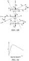
- FIGS. 1A-1Cdepict coordinate systems in reference to embodiments of certain components of a ball-planetary continuously variable transmission (CVT).
- CVTcontinuously variable transmission
- CVT 100includes planets 108 in contact with sun 110 and traction rings 102 , 104 .
- Planets 108are interposed between and in contact with first traction ring 102 and second traction ring 104 at, respectively, first angular position 112 and second angular position 114 .
- FIG. 1Adepicts global coordinate system 150 (defined herein to include axes x g , y g , z g ) and planet-centered coordinate system 160 (defined herein to include axes x, y, z).
- Global coordinate system 150is oriented with respect to longitudinal axis 15 of CVT 100 , with the z g -axis coinciding with longitudinal axis 15 about which planets 108 are arranged.
- Planet-centered coordinate system 160has its origin at the geometric center of each planet 108 , with the y-axis perpendicular to longitudinal axis 15 , and the z-axis parallel to longitudinal axis 15 .
- Each of planets 108has axle 103 defining a planet axis of rotation (defined herein as planet axis 106 ).
- Planet axis 106may be angularly oriented in the y-z plane relative to the x-axis at tilt angle (gamma) 118 .
- Tilt angle (gamma) 118determines the kinematic ratio between the rotational speeds of traction rings 102 and 104 .
- Each planet 108has a rotational velocity w (omega) about planet axis 106 , depicted in FIG. 1A as planet rotational velocity 122 .
- Planet axis 106is defined by planet axle 103 .
- the x-axisis directed into the plane of the page (though not shown precisely as such in FIG. 1A ), and the z-axis is parallel to longitudinal axis 15 .
- tilt angle (gamma) 118is generally defined in the y-z plane.
- planet-centered coordinate system 160is resolved further to illustrate the angular adjustments of each planet axis 106 used in embodiments of skew control systems.
- tilt angle (gamma) 118can be derived by rotating coordinate system 160 (with planet axis 106 in the y-z plane) about the x-axis to achieve first relative coordinate system 170 (x′, y′, z′).
- first relative coordinate system 170planet axis 106 coincides with the z′-axis.
- skew angle (zeta) 120can be derived by rotating coordinate system 170 about the y-axis (not the y′-axis) to achieve second relative coordinate system 180 (x′′, y′′, z′′).
- second relative coordinate system 180planet axis 106 coincides with the z′′-axis.
- Skew angle (zeta) 120is the angular orientation relative to the y-axis in the x-z plane of the planet axis 106 .
- tilt angle (gamma) 118is controlled, at least in part, through an adjustment of skew angle (zeta) 120 .
- skew conditionrefers to an orientation of planet axes 106 such that a non-zero skew angle (zeta) 120 relative to the y-axis exists.
- inducement of a skew conditionimplies an inducement of planet axes 106 to align at non-zero skew angle (zeta) 120 .
- certain spin-induced forcesalso act on planet 108 .
- first traction ring 102drives planet 108 at contact 1, and planet 108 transmits power to second traction ring 104 at contact 2.
- Traction sun 110contacts traction planet 108 at contact 3, which may be a single point (shown) or may collectively refer to multiple contact points (not shown here for simplicity).
- Contact points 1, 2 and 3are arranged in FIG. 1D to reflect a view of the x-z plane as seen from above CVT 100 . However, for ease of understanding, since contact areas 1, 2 and 3 are not coplanar, contact-centered coordinate systems are used in FIG.
- contact areas 1, 2 and 3can be illustrated with the x-z plane.
- Subscripts 1, 2, and 3are used to denote the specific contact area for contact-centered coordinate systems.
- the z 1 , z 2 , and z 3 axesintersect at the center of a spherical traction planet 108 .
- the surface velocity of first traction ring 102is denoted in the negative x 1 direction by vector V r1 and the surface velocity of planet 108 is represented by a vector V p1 ; the angle formed between the vectors V r1 and V p1 is approximately skew angle 120 .
- the resulting relative surface velocity between first traction ring 102 and traction planet 108is represented by a vector V r1/p .
- the surface velocity of traction sun 110is represented by vector V sv and the surface velocity of traction planet 108 is represented by vector V ps ; the angle formed between V sv and V ps is approximately skew angle 120 .
- the relative surface velocity between traction planet 108 and traction sun 110is represented by vector V sv/p .
- the surface velocity of traction planet 108 at contact area 2is represented by vector V p2 and the surface velocity of second traction ring 104 is represented by vector V r2 ; the angle formed between V p2 and V r2 is approximately skew angle 120 ; the relative surface velocity between traction planet 108 and second traction ring 104 is represented by vector V r2/p .
- FIG. 1Edepicts a generalized, representative traction curve that can be applied at each of contact areas 1, 2, 3, illustrating a relationship between the traction coefficient ⁇ and the relative velocity between contacting components.
- the traction coefficient ⁇is indicative of the capacity of the fluid to transmit a force.
- the relative velocitysuch as V r1/p , can be a function of skew angle 120 .
- the traction coefficient ⁇is the vector sum of the traction coefficient in the x-direction ( ⁇ x ) and the traction coefficient in the y-direction ( ⁇ y ) at contact area 1, 2, or 3.
- traction coefficient ⁇is a function of the traction fluid properties, the normal force at the contact area, and the velocity of the traction fluid in the contact area, among many other things.
- the traction coefficient ⁇increases with increasing relative velocities of components, until the traction coefficient ⁇ reaches a maximum capacity after which the traction coefficient ⁇ decreases with increasing relative velocities of components. Consequently, in the presence of skew angle 120 (i.e., under a non-zero skew condition), forces are generated at contact areas 1, 2, 3 around the traction planet 108 due to kinematic conditions.
- V r1/pBased on the traction curve depicted in FIG. 1E and the diagrams depicted in FIGS. 1D and 1F , V r1/p generates a traction force parallel to V r1/p with a component side force F s1 .
- Increasing skew angle 120increases V r1/p and, thereby increases force F s1 (according to the general relationship illustrated in FIG. 1D ).
- V sv/pgenerates force F ss
- V r2/pgenerates force F s2 .
- Forces F s1 , F ss , and F s2combine to create a net moment about traction planet 108 in the y-z plane.
- the traction coefficient ⁇is a function of relative velocity between contacting components
- the traction coefficients ⁇ y1 , ⁇ y2 , and ⁇ ysare consequently a function of skew angle 120 as related by the kinematic relationship.
- a momentis an acceleration of inertia and the moment will generate a tilt angle acceleration ⁇ umlaut over ( ⁇ ) ⁇ . Therefore, the rate of change of tilt angle ⁇ dot over ( ⁇ ) ⁇ is a function of skew angle 120 .
- FIG. 1Gdepicts a top view of one embodiment of traction planet 108 having non-zero skew angle (zeta) 120 , which results in planet axis of rotation 106 being non-parallel (in the y g -z g plane) to longitudinal axis 15 of CVT 100 and rotational velocity 122 of traction planet 108 is not coaxial with the z-axis.
- Skew angle 120generates forces for motivating a change in tilt angle 118 .
- traction planet 108would have rotational velocity 122 about an axis z′′, and tilt angle 118 would be formed between axis z′′ and the y-z plane.
- Embodiments of CVTs disclosed hereinare capable of operating according to the above-mentioned principles during operation in forward direction and reverse direction, may switch between operation in forward direction and reverse direction, and may be controlled using various control schemes that enable switching between operation in forward direction and reverse direction.
- embodiments disclosed hereininclude a vehicle or equipment with a transmission, drivetrain, CVT or a control system for a CVT having a control system coupled to a plurality of trunnions coupled to each axle in a plurality of axles, wherein the control system is capable of misaligning the axles to adjust a speed ratio over a range of speed ratios between underdrive and overdrive (and including 1:1), and configurable to operate in forward and reverse directions and further configurable to operate according to different control strategies for stability and sensitivity.
- embodiments disclosed hereinmay operate in either forward direction or reverse direction, allowing a CVT to be continuously adjusted to maintain a constant output speed for varying input speeds and torques, to maintain a speed ratio for variable input speeds and torques or variable output speeds and torques, or to provide variable output speeds for constant input speeds and torques.
- embodimentsmay proactively, simultaneously or reactively adjust a speed ratio of a CVT.
- control of a CVT between operation in forward direction and reverse directionmay include radially translating trunnion extensions to change the orientation of trunnions relative to a pitch circle to accommodate a switch in the direction of rotation and compensating for the corresponding switch between overdrive and underdrive by axially translating trunnion extensions to apply a skew condition to maintain the skew angle (zeta) imparted on the planets.
- the processes of orienting the trunnions to an offset angle (psi) relative to the pitch circle to configure the CVT for switching between operation in forward direction and reverse direction and applying a skew angle (zeta) to adjust a tilt angle (gamma) of the CVT adjust the speed ratio of the CVT to any speed ratio between underdrive and overdrivemay be performed independently, allowing for multiple possible control schemes for a CVT, such as an example CVT 200 described below.
- embodimentsmay translate trunnion extensions radially inward or outward of a pitch circle to orient trunnions to have a positive or negative offset angle (psi). Furthermore, embodiments disclosed herein may adjust tilt angles (gamma), angular positioning (beta), skew angles (zeta) and offset angles (psi) independently or concurrently, allowing a control system to switch operation of CVT between forward and reverse rotation, and adjust or maintain a speed ratio.
- Couplings between trunnions and trunnion extensionsallow trunnion extensions to move axially but allow trunnions to rotate to a target offset angle (psi) about their respective z-axes.
- Embodiments disclosed hereinmay advantageously orient trunnions at an offset angle (psi) and adjust a tilt angle (gamma) of axles for a CVT concurrently or independently, allowing for controlled operations in both forward and reverse directions, wherein an offset angle (psi) sign can change at any ratio range, and a transmission ratio (speed or torque) may be adjusted at any offset angle (psi).
- a control system for a vehicle operating a CVTdetermines that a rollback scenario is occurring or likely to occur, a control system may initiate radial movement of couplings or trunnion extensions or change an orientation of trunnions to change the offset angle (psi) sign relative to the pitch circle.
- Embodiments of a control systemmay also determine a control sensitivity.
- the control sensitivityis a function of the offset angle (psi) and dimensions of components including links. Small offset angles (psi) or short link lengths require less axial movement to achieve the same tilt angle (gamma) and allow for faster ratio adjustments but may be less stable. Larger offset angles (psi) or longer link lengths require more axial movement to achieve the same tilt angle (gamma) and may limit ratio adjustment rates but may be more stable.
- Embodiments of a control systemmay determine a control sensitivity based on operator input, sensor information, or some combination.
- Embodimentsmay also operate according to a first control sensitivity under a first set of conditions and change to a second control sensitivity under a second set of conditions.
- a first set of conditionsmay correspond to operating a CVT in a forward direction and a second set of conditions may correspond to operating the CVT in a reverse direction, operating in a forward direction when reversal of rotation direction is imminent, operating in a forward direction when reversal of rotation direction is probable, in a forward direction when reversal of rotation direction is possible, operating in a forward direction under an increased load, or operating in a forward direction at higher vehicle speed.
- Other conditionsmay be based on sensor inputs.
- a control systemmay determine a control sensitivity that limits the axial movement of a coupling and reduce the offset angle (psi) to allow for reduced axial movement of the coupling or may increase the offset angle (psi) and reduce the frequency of commands for adjusting the axial movement of the coupling.
- embodiments disclosed hereinmay be generally directed to a ball planetary continuously variable transmission (CVT) comprising a plurality of spherical planets between and in contact with two traction rings and a sun, each planet having an axle and a geometric center through which an x-axis, y-axis and z-axis intersect, wherein the plurality of geometric centers define a pitch circle for the plurality of planets, wherein each axle extends through a central bore of a spherical planet and defines the z-axis and an axis of rotation.
- CVTcontinuously variable transmission
- each planet axleis capable of tilting in a first skew plane, and has a skew angle defined as an angle between the central axis and the planet axle, and in a second tilting plane defining a tilt angle as the angle between the central axis and the planet axle, wherein the tilt angle defines a transmission ratio of the transmission.
- Some embodimentshave a first carrier half coaxial with and rotatable about the central axis, the first carrier half coupled by a plurality of links to a first end of each of the planet axles; and a second carrier half coaxial with and rotatable about the central axis, the second carrier half coupled by a plurality of links to a second end of each of the planet axles.
- the first carrier half and second carrier halfare rotatable with respect to each other to define an angular position, wherein relative rotation of the first and second carrier halves defines a non-zero angular position that imparts a non-zero skew angle, and wherein a non-zero skew angle imparts an adjustment to the tilt angle, resulting in a change in the transmission ratio of the CVT.
- a plurality of couplingscouple the plurality of links to the first and second carrier halves, wherein the plurality of couplings are adapted to allow the plurality of links to rotate out of plane with the first and second carrier halves to facilitate the tilting of the planet axles.
- the plurality of couplingsmay be ball joints.
- the plurality of linksmay be flexible.
- the CVTfurther includes a pitch circle coaxial about the central axis and having a radius equal to a plurality of centers of the planet assemblies, a plurality of connections that connect the plurality of links to the plurality of planet axles.
- An effective offset angleis defined by the tangent of the pitch circle at a respective one of the plurality of connections and a line between an associated one of the plurality of connections and an associated one of the plurality of couplings.
- the effective offset anglemay be positive when the plurality of links are located radially outside of the pitch circle, a positive offset angle associated with a forward direction of rotation, and the effective offset angle may be negative when the plurality of links are located radially inside of the pitch circle, a negative offset angle associated with a reverse direction of rotation.
- the CVTfurther includes an actuator adapted to adjust the radial position of the plurality of couplings in order to adjust the effective offset angle.
- Certain of these embodimentsinclude an actuator adapted to adjust the radial position of the plurality of couplings to a positive effective offset angle when the CVT is rotating in the forward direction, and adapted to adjust the radial position of the plurality of couplings to a negative offset angle when the CVT is rotating in the reverse direction.
- embodiments disclosed hereinmay be directed to a continuously variable transmission comprising a plurality of spherical planets between and in contact with two traction rings and a sun, each planet having a geometric center through which an x-axis, y-axis and z-axis intersect, wherein the plurality of geometric centers define a pitch circle for the plurality of planets, wherein an axle extends through a central bore of each of the plurality of spherical planets and defines the z-axis and an axis of rotation.
- the control systemcomprises a plurality of trunnions, wherein each trunnion is coupled to each end of an axle and extends around a spherical planet to a coupling.
- the plurality of trunnionsare oriented at an offset angle (psi).
- orientation of the plurality of traction planetssuch that the offset angle (psi) has a positive sign configures the CVT for operation in a first direction and orientation of the plurality of traction planets such that the offset angle (psi) has a negative sign configures the CVT for operation in a second direction.
- the plurality of trunnionsare oriented such that the offset angle (psi) has a positive sign for operation in a forward direction and a negative sign for operation in a reverse direction. In some embodiments in which the plurality of couplings trail the spherical planets, the plurality of trunnions are oriented such that the offset angle (psi) has a negative sign for operation in a forward direction and a positive sign for operation in a reverse direction.
- axial translation of the plurality of couplingsimparts a skew condition on the plurality of traction planets to adjust a speed ratio of the CVT.
- the CVTfurther comprises a synchronizing ring coupled to the plurality of couplings
- axial translation of the synchronizing ringaxially translates the plurality of couplings to adjust the speed ratio of the CVT. The orientation of the plurality of trunnions is controlled by radial translation of the plurality of couplings.
- an axial force applied to the plurality of axlesimparts a skew condition on the plurality of traction planets to adjust a speed ratio of the CVT.
- a synchronizeris coupled to at least one end of each axle, axial translation of the synchronizer axially translates the plurality of axles to adjust a speed ratio of the CVT.
- the synchronizercomprises a control disc positioned on one side of the CVT
- the control disccomprises a plurality of slots and an end of each axle is coupled to a slot of the plurality of slots, wherein an axial force is applied to the control disc in a first direction or a second direction opposite the first direction to adjust a speed ratio of the CVT.
- the synchronizercomprises a first control disc positioned on a first side of the plurality of slots and a second control disc positioned on a second side of the plurality of slots opposite the first control disc, an axial force is applied to the first control disc to apply an axial force to the axles in a first direction and an axial force is applied to the second control disc to apply an axial force to the axles in a second direction.
- the synchronizercomprises a plurality of arms with each arm coupled to an axle of the plurality of axles, an axial force applied to the plurality of arms applies an axial force to the plurality of axles to adjust a speed ratio of the CVT.
- embodiments disclosed hereinmay be directed to a method of controlling a continuously variable transmission (CVT) comprising a plurality of spherical planets between and in contact with two traction rings and a sun, each planet having a geometric center through which an x-axis, y-axis and z-axis intersect, wherein the plurality of geometric centers define a pitch circle for the plurality of planets, wherein an axle extends through a central bore of each of the plurality of spherical planets and defines the z-axis and an axis of rotation for that planet, and a plurality of trunnions, wherein each trunnion is coupled to each end of an axle and extends around a spherical planet coupled to the axle.
- CVTcontinuously variable transmission
- the methodcomprises rotating the plurality of trunnions about their respective z-axes to an offset angle (psi).
- An offset angle (psi) having a positive signconfigures the CVT for operation in a first direction of rotation
- an offset angle (psi) having a negative signconfigures the CVT for operation in a second direction of rotation.
- each trunnionis coupled to a trunnion extension via a coupling with multiple degrees of freedom
- the methodcomprises axially translating the plurality of trunnion extensions to impart a skew angle (zeta) on the plurality of traction planets to cause a change in a speed ratio of the CVT, whereby the couplings allow forces generated by the axial translation to tilt the planets.
- zetaskew angle
- each trunnionis coupled to a trunnion extension with limited degrees of freedom
- the methodcomprises applying an axial force to the plurality of axles to impart the skew angle (zeta) on the plurality of traction planets to cause a change in a speed ratio of the CVT, whereby the couplings react forces generated by the axial translation of the planets to tilt the planets.
- the methodcomprises axially fixing the plurality of couplings, wherein adjusting the speed ratio of the CVT comprises applying an axial force to the plurality of axles.
- the methodcomprises axially fixing the plurality of axles to the plurality of traction planets, wherein adjusting the speed ratio of the CVT comprises axially translating the plurality of couplings.
- the methodcomprises determining a first direction of rotation for the CVT; rotating the plurality of trunnions about their respective z-axes to a first offset angle (psi) for operation in the first direction of rotation; determining a change in direction of rotation of the CVT to a second direction of rotation; and rotating the plurality of trunnions about their respective z-axes to a second offset angle (psi) for operation in the second direction of rotation of the CVT.
- the methodcomprises determining a first direction of operation; configuring the CVT for operation at a first offset angle (psi) for the first direction of rotation based on one or more of a first user input, a first operating condition and a first environmental condition; and configuring the CVT for operation at a second offset angle (psi) for the first direction of rotation based on one or more of a second user input, a second operating condition and a second environmental condition, wherein the first offset angle (psi) or the second offset angle (psi) is selected for stable operation or sensitivity.
- embodiments disclosed hereinmay be directed to a control system for a continuously variable transmission (CVT) comprising a plurality of spherical planets between and in contact with two traction rings and a sun, each planet having a geometric center through which an x-axis, y-axis and z-axis intersect, wherein the plurality of geometric centers define a pitch circle for the plurality of planets, wherein an axle extends through a central bore of each of the plurality of spherical planets and defines the z-axis and an axis of rotation.
- CVTcontinuously variable transmission
- the control systemcomprises a controller communicatively coupled to a plurality of sensors and further coupled to a plurality of trunnions coupled to the plurality of axles, wherein each trunnion is coupled to each end of an axle and extends around a spherical planet coupled to that axle.
- the controllermay receive signals related to performance of the CVT, performance of a prime mover coupled to the CVT, signals related to performance of a vehicle associated with the CVT, signals related to the environment, and user inputs.
- the controllermay analyze the signals and configure the CVT. In some embodiments, the controller may configure the CVT for forward or reverse rotation. In some embodiments, the controller may configure the CVT for a desired stability or sensitivity.
- the controllermay compare the signals with values stored in memory, determine an operating condition is present and configure the CVT according to the operating condition.
- the operating conditionmay be a rollback condition, in which a vehicle containing the CVT is in a rollback condition or about to encounter a rollback condition.
- the controllermay analyze the signals and determine a rollback condition is possible and configure the CVT for increased sensitivity.
- Configuring the CVT for increased sensitivitymay include adjusting trunnions to a smaller offset angle (psi). In some embodiments, the smaller offset angle may be less than 10 degrees.
- configuring the CVT for increased sensitivitymay include increasing the rate at which sensors send signals to the controller.
- the controllermay configure the CVT for increased stability, which may include adjusting trunnions to a higher offset angle (psi). Adjusting the trunnions may comprise radially translating a control point for each trunnion to a radial position relative to a pitch circle or rotating the trunnions to an offset angle (psi).
- Each trunnioncomprises a coupling, wherein a control point is defined along a line passing through the geometric center of each traction planet and the coupling for that traction planet, wherein a position of a plurality of control points radially outside the pitch circle configures the CVT for a first direction, wherein a position of the plurality of control points radially inside the pitch circle configures the CVT for a second direction opposite the first direction.
- An axial translation of the plurality of control points, an axial force applied to the plurality of axles, or a combination thereofmisaligns the plurality of axles relative to a longitudinal axis of the CVT to adjust a tilt angle of the plurality of planets.
- the controllermay position the plurality of control points radially inward of the pitch circle for operation in a forward direction of rotation or radially outward of the pitch circle for operation in a reverse direction of rotation. In some embodiments in which the plurality of couplings trail the spherical planets, a controller may position the plurality of control points radially outward of the pitch circle for operation in a forward direction of rotation or radially inward of the pitch circle for a reverse direction of rotation.
- the plurality of axlesare axially fixed to the plurality of planets and the CVT further comprises a plurality of trunnion extensions coupled to the plurality of couplings and a synchronizing ring.
- a controllermay control a radial position of the plurality of couplings by radial translation of the plurality of trunnion extensions.
- a controllermay command an axial translation of the synchronizing ring to axially translate the plurality of couplings to adjust the speed ratio of the CVT.
- the couplingsare fixed axially, and a controller may command an axial force be applied to the plurality of axles to impart a non-zero skew condition to the plurality of planets.
- a synchronizeris coupled to at least one end of each axle, wherein a controller commanding an axial force applied to the synchronizer misaligns the plurality of axles to adjust a tilt angle of the plurality of traction planets.
- the synchronizercomprises a control disc positioned on one side of the CVT. The control disc has a plurality of slots and an end of each axle is coupled to a slot of the plurality of slots.
- the synchronizercomprises a first control disc positioned on a first side of the plurality of slots and a second control disc positioned on a second side of the plurality of slots opposite the first control disc, wherein a controller commanding an axial force applied to the first control disc applies an axial force to the axles in a first direction to impart a non-zero skew condition to adjust a tilt angle of the plurality of traction planets toward underdrive, or an axial force applied to the second control disc applies an axial force to the axles in a second direction to impart a non-zero skew condition to adjust a tilt angle of the plurality of traction planets toward overdrive.
- the synchronizercomprises a plurality of arms.
- Each rigid memberis coupled to an axle of the plurality of axles, wherein an axial force applied to the plurality of arms applies an axial force to the plurality of axles to adjust a tilt angle of the plurality of traction planets.
- embodiments disclosed hereinmay be generally directed to a method of controlling a continuously variable transmission (CVT) comprising a plurality of spherical planets between and in contact with two traction rings and a sun, each planet having a geometric center through which an x-axis, y-axis and z-axis intersect, wherein the plurality of geometric centers define a pitch circle for the plurality of planets, wherein an axle extends through a central bore of each of the plurality of spherical planets and defines the z-axis and an axis of rotation for that planet, and a plurality of trunnions, wherein each trunnion is coupled to each end of an axle and extends around a spherical planet coupled to that axle, wherein each trunnion comprises a coupling, wherein a control point is defined along a line passing through the geometric center of each traction planet and the coupling for that traction planet.
- CVTcontinuously variable transmission
- rotating the plurality of trunnions about their respective z-axes to an offset angle (psi)comprises determining a control scheme and rotating the plurality of trunnions to the offset angle (psi) based on the control scheme.
- the plurality of trunnionsare rotated to a larger angle associated with a control scheme selected for stable operation or are rotated to a smaller angle associated with a control scheme selected for increased sensitivity.
- embodiments disclosed hereinmay be generally directed to a control system for a ball planetary continuously variable transmission (CVT) comprising a plurality of spherical planets between and in contact with two traction rings and a sun, each planet having a geometric center through which an x-axis, y-axis and z-axis intersect, wherein the plurality of geometric centers define a pitch circle for the plurality of planets, wherein an axle extends through a central bore of each of the plurality of spherical planets and defines the z-axis and an axis of rotation.
- CVTcontinuously variable transmission
- control systemcomprises a plurality of trunnions coupled to the plurality of axles, wherein each trunnion comprises a first link coupled to a first end of an axle, a second link coupled to a second end of the axle, and a center link coupled to the first link and the second link.
- a first actuatormay configure the plurality of trunnions to an offset angle (psi) relative to the pitch circle.
- a second actuatormay rotate the center link.
- a controller communicatively coupled to the actuator and a plurality of sensorsmay be configured to receive signals from the plurality of sensors, determine a direction of rotation for the CVT, send a first signal to the first actuator to adjust the offset angle (psi) of the plurality of trunnions and send a signal to the second actuator to impart a skew angle (zeta) on the plurality of axles to adjust a tilt angle.
- the CVTis configured for operation in a forward direction if the plurality of trunnions lead the plurality of planets and the offset angle (psi) is positive, the CVT is configured for operation in a forward direction.
- the CVTis configured for operation in forward direction.
- a speed ratio of the CVTmay be based on the tilt angle, the skew angle and the offset angle.
- the controllermay receive signals related to performance of the CVT, performance of a prime mover coupled to the CVT, signals related to performance of a vehicle associated with the CVT, signals related to the environment, and user inputs.
- the controllermay analyze the signals and configure the CVT.
- the controllermay configure the CVT for forward or reverse rotation.
- the controllermay configure the CVT for a desired stability or sensitivity.
- the controllermay compare the signals with values stored in memory, determine an operating condition is present and configure the CVT according to the operating condition.
- the operating conditionmay be a rollback condition, in which a vehicle containing the CVT is in a rollback condition or about to encounter a rollback condition.
- the controllermay analyze the signals and determine a rollback condition is possible and configure the CVT for increased sensitivity.
- the controlleris further configured to change the offset angle (psi) in response to determining a change in the direction of rotation or receiving an input to change the direction of rotation.
- the controlleris further configured to adjust the offset angle (psi) to have a larger magnitude for a first control scheme for stable control or to have a smaller magnitude for a second control scheme for increased sensitivity.
- embodiments disclosed hereinmay be generally directed to a ball planetary continuously variable transmission (CVT) comprising a plurality of spherical planets between and in contact with two traction rings and a sun, each planet having a geometric center through which an x-axis, y-axis and z-axis intersect, wherein the plurality of geometric centers define a pitch circle for the plurality of planets, wherein an axle extends through a central bore of each of the plurality of spherical planets and defines the z-axis and an axis of rotation, and a control system.
- CVTcontinuously variable transmission
- the control systemmay comprise a plurality of trunnions coupled to the plurality of axles, a first actuator for configuring the plurality of trunnions to an offset angle (psi) relative to the pitch circle, a second actuator for rotating the center link and a controller communicatively coupled to the actuator and a plurality of sensors.
- each trunnioncomprises a first link coupled to a first end of an axle, a second link coupled to a second end of the axle, and a center link coupled to the first link and the second link.
- the controlleris configured to receive signals from the plurality of sensors, determine a direction of rotation for the CVT, send a first signal to the first actuator to adjust the offset angle (psi) of the plurality of trunnions, and send a signal to the second actuator to impart a skew angle (zeta) on the plurality of axles to adjust a tilt angle.
- a controllermay configure the CVT for operation in a forward direction if the plurality of trunnions lead the plurality of planets and the offset angle (psi) is positive, a controller may configure the CVT for operation in a forward direction.
- a controllermay configure the CVT for operation in forward direction.
- a speed ratio of the CVTmay be based on the tilt angle, the skew angle and the offset angle.
- the first link and the second linkcomprise rigid members.
- embodiments disclosed hereinmay be generally directed to a control system for a continuously variable transmission (CVT) comprising a plurality of spherical planets between and in contact with two traction rings and a sun, each planet having a geometric center through which an x-axis, y-axis and z-axis intersect, wherein the plurality of geometric centers define a pitch circle for the plurality of planets, wherein an axle extends through a central bore of each of the plurality of spherical planets and defines the z-axis and an axis of rotation.
- CVTcontinuously variable transmission
- the control systemcomprises a first carrier member located on a first side of the CVT, a first plurality of arms on the first side of the CVT, a second carrier member located on a second side of the CVT, a second plurality of arms, a first actuator for rotating one or more of the first carrier and the second carrier to an angular orientation of the first carrier relative to the second carrier member, and a controller communicatively coupled to the actuator and a plurality of sensors.
- a first end of each arm of the first plurality of armsis coupled to a first end of an axle and a second end of each arm of the first plurality of arms is coupled to the first carrier member.
- a first end of each arm of the second plurality of armsis coupled to a second end of an axle and a second end of each arm of the second plurality of arms is coupled to the second carrier member.
- the controllerconfigured to receive signals from the plurality of sensors and command the first actuator to rotate the first carrier member relative to the second carrier member, wherein rotation of the first carrier member relative to the second carrier member imparts a skew condition on the plurality of planets to tilt the plurality of axles to a tilt angle associated with a speed ratio for the CVT.
- the first plurality of armsare movable relative to the first carrier member and the second plurality of arms are movable relative to the second carrier member and the control system further comprises a second actuator for radially rotating one or more of the first plurality of arms and the second plurality of arms to an offset angle (psi) to configure the CVT for operation in a forward direction of rotation or reverse direction of rotation.
- the controllermay receive signals related to performance of the CVT, performance of a prime mover coupled to the CVT, signals related to performance of a vehicle associated with the CVT, signals related to the environment, and user inputs.
- the controllermay analyze the signals and configure the CVT. In some embodiments, the controller may configure the CVT for forward or reverse rotation.
- the controllermay configure the CVT for a desired stability or sensitivity.
- the controllermay compare the signals with values stored in memory, determine an operating condition is present and configure the CVT according to the operating condition.
- the operating conditionmay be a rollback condition, in which a vehicle containing the CVT is in a rollback condition or about to encounter a rollback condition.
- the controllermay analyze the signals and determine a rollback condition is possible and configure the CVT for increased sensitivity.
- the controlleris further configured to change the offset angle (psi) in response to determining a change in the direction of rotation or receiving an input to change the direction of rotation.
- the controlleris further configured to adjust the offset angle (psi) to have a larger magnitude for a first control scheme for stable control or to have a smaller magnitude for a second control scheme for increased sensitivity.
- the controlleris configured to receive a user input for one or more of a direction of rotation, a control mode, and a speed ratio.
- orientation of the first plurality of arms to a positive first offset angle (psi) relative to the first carrier member and orientation of the second plurality of arms to a positive second offset angle (psi) relative to the second carrier memberconfigures the CVT for operation in a first direction of rotation
- orientation of the first plurality of arms to a negative first offset angle (psi) relative to the first carrier member and orientation of the second plurality of arms to a negative second offset angle (psi) relative to the second carrier memberconfigures the CVT for operation in a second direction of rotation.
- orientation of the first plurality of arms to a positive first offset angle (psi) and orientation of the second plurality of arms to a positive second offset angle (psi)configures the CVT for operation in forward direction and orientation of the first plurality of arms to a negative first offset angle (psi) and orientation of the second plurality of arms to a negative second offset angle (psi) configures the CVT for operation in reverse direction
- orientation of the first plurality of arms to a positive first offset angle (psi) and orientation of the second plurality of arms to a positive second offset angle (psi)configures the CVT for operation in reverse direction and orientation of the first plurality of arms to a negative first offset angle (psi) and orientation of the second plurality of arms to a negative second offset angle (psi) configures the CVT for operation in forward direction.
- embodiments disclosed hereinmay be generally directed to a continuously variable transmission (CVT) comprising a plurality of spherical planets between and in contact with two traction rings and a sun, each planet having a geometric center through which an x-axis, y-axis and z-axis intersect, wherein the plurality of geometric centers define a pitch circle for the plurality of planets, wherein an axle extends through a central bore of each of the plurality of spherical planets and defines the z-axis and an axis of rotation.
- CVTcontinuously variable transmission
- orientation of the first plurality of arms to a positive first offset angle (psi) relative to the first carrier member and orientation of the second plurality of arms to a positive second offset angle (psi) relative to the second carrier memberconfigures the CVT for operation in a first direction of rotation.
- orientation of the first plurality of arms to a negative first offset angle (psi) relative to the first carrier member and orientation of the second plurality of arms to a negative second offset angle (psi) relative to the second carrier memberconfigures the CVT for operation in a second direction of rotation.
- orientation of the first plurality of arms to a positive first offset angle (psi) and orientation of the second plurality of arms to a positive second offset angle (psi)configures the CVT for operation in forward direction and orientation of the first plurality of arms to a negative first offset angle (psi) and orientation of the second plurality of arms to a negative second offset angle (psi) configures the CVT for operation in reverse direction.
- orientation of the first plurality of arms to a positive first offset angle (psi) and orientation of the second plurality of arms to a positive second offset angle (psi)configures the CVT for operation in reverse direction and orientation of the first plurality of arms to a negative first offset angle (psi) and orientation of the second plurality of arms to a negative second offset angle (psi) configures the CVT for operation in forward direction.
- at least one of the first link and the second linkis formed as a resilient member.
- at least one of the first link and the second linkis formed with directional resiliency.
- embodiments disclosed hereinmay be generally directed to a method of adjusting a speed ratio of a continuously variable transmission (CVT) comprising a plurality of spherical planets between and in contact with two traction rings and a sun, each planet having a geometric center through which an x-axis, y-axis and z-axis intersect, wherein the plurality of geometric centers define a pitch circle for the plurality of planets, wherein an axle extends through a central bore of each of the plurality of spherical planets and defines the z-axis and an axis of rotation.
- CVTcontinuously variable transmission
- the methodcomprises rotating a first carrier member relative to a second carrier member, wherein the first carrier member is coupled to a first plurality of arms, wherein each arm of the first plurality of arms is coupled to a first end of an axle of a traction planet, wherein the second carrier member is coupled to a second plurality of arms, wherein each arm of the second plurality of arms coupled to a second end of the axle of a traction planet, wherein rotating the first carrier member relative to the second carrier member misaligns the plurality of axes of rotation relative to a longitudinal axis of the CVT to change a speed ratio of the CVT.
- the methodincludes adjusting an offset angle (psi) for the first plurality of arms and the second plurality of arms, wherein a positive offset angle (psi) configures the CVT for operation in a first direction of rotation, wherein a negative offset angle (psi) configures the CVT for operation in a second direction of rotation.
- adjusting an offset angle (psi) for the first plurality of arms and the second plurality of armscomprises adjusting a magnitude of the offset angle (psi).
- the magnitudeis based on a control scheme, wherein the offset angle (psi) is adjusted to a larger magnitude for stable control or adjusted to a smaller magnitude for increased sensitivity.
- one or more of the control scheme, the direction of rotation and the speed ratioare user input received from a user interface.
- FIG. 1Adepicts a schematic diagram of a continuously variable transmission relative to global and planet-centered coordinate systems
- FIGS. 1B and 1Cdepict schematic diagrams of planet-centered coordinate systems and relative coordinate systems, illustrating relationships between skew and tilt in ball-planetary continuously variable transmissions;
- FIG. 1Ddepicts a schematic diagram of certain kinematic relationships between contacting components of a CVT, illustrating how the inducement of a skew condition generates forces that tend to adjust a tilt angle;
- FIG. 1Edepicts a generalized, representative traction curve that can be applied at each of contact areas 1, 2, 3, illustrating a relationship between the traction coefficient ⁇ and the relative velocity between contacting components;
- FIGS. 1F and 1Gdepict front and top schematic diagrams, illustrating traction forces exerted relative to a planet under non-zero skew conditions
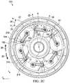
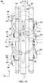
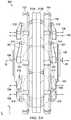
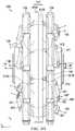
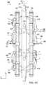
- FIGS. 2A-2Jdepict partial perspective, side and front views of a CVT, illustrating one embodiment of a control system capable of operation in forward direction and reverse direction;
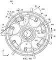
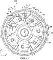
- FIGS. 3A-3Jdepict front partial views of a CVT, illustrating one embodiment of a control system capable of operation in forward direction and reverse direction;
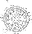
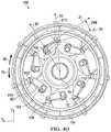
- FIGS. 4A-4Odepict partial perspective, side and front views of a CVT, illustrating one embodiment of a control system capable of operation in forward direction and reverse direction.
- Embodiments disclosed hereincomprise ball-planetary continuously variable transmissions (CVTs) in which a plurality of planets are interposed between and in contact with traction rings and a sun, in which tilting of the planets changes a speed ratio of the CVT.
- CVTscontinuously variable transmissions
- Speed ratiomay vary between underdrive and overdrive.
- underdrivepower enters a first traction ring with a first torque and a first speed and is transferred through planets to a second traction ring with a second torque higher than the first torque and a second speed lower than the first speed.
- overdrivepower enters the first traction ring with a first torque and a first speed and is transferred through planets to the second traction ring with a lower torque greater than the first torque and a second speed higher than the first speed.
- Each planethas a geometric center, with an x-axis, y-axis and z-axis for that planet intersecting at its geometric center.
- the geometric centers of planets arranged angularly around a longitudinal axiscollectively define a pitch circle for the plurality of planets.
- Each planetis coupled to an axle.
- Each axledefines an axis of rotation, which is aligned with a z-axis of a planet. Tilting axles to a non-zero tilt angle (gamma) causes contact points between planets and traction rings to change, adjusting a speed ratio of a CVT.
- gammanon-zero tilt angle
- axialrefers to a direction along or parallel to a longitudinal axis of the CVT.
- radialrefers to a direction perpendicular to a longitudinal axis of the CVT.
- direction 25refers to a forward rotation (also referred to as a design direction) and direction 26 refers to reverse rotation, and in the embodiments illustrated power is transferred from first traction ring 102 to second traction ring 104 .
- Embodiments disclosed hereinmay include a control system configurable to adjust a CVT, such as CVT 200 , to a target speed ratio for operation in a forward direction or a reverse direction, including maintaining a speed ratio during a switch between operation in forward direction and operation in a reverse direction, and operate according to a control scheme for increased stability or sensitivity.
- FIGS. 2A-2Jdepict front and side views of CVT 200 comprising a plurality of planets 108 interposed between traction rings 102 , 104 and sun 110 , illustrating CVT 200 configured for operation at 1:1, underdrive and overdrive speed ratios in forward and reverse directions.
- planets 108are coupled to tiltable axles 103 that define axes of rotation 106 which are coaxial with the z-axes for planets 108 .
- Axles 103are coupled to planets 108 such the planets 108 may rotate about axes of rotation 106 .
- bearings 107may facilitate rotation of axles 103 in trunnions 220 .
- bearings 107allow axles 103 to rotate relative to trunnions 220 but axially fix axles 103 relative to trunnions 220 .
- Trunnions 220may be machined or otherwise formed as rigid members for coupling to axles 103 to allow a control system to adjust an orientation of planets 108 in operation to adjust a speed ratio in forward direction and reverse direction. Trunnions 220 are rotatably coupled to axles 103 on either side of planets 108 .
- FIGS. 2A-2Jdepict embodiments in which trunnions 220 are formed such that axles 103 and bearings 107 may be accessible via openings 223 .
- trunnions 220may be formed with smaller openings 223 such that only axles 103 are accessible, including without openings 223 .
- Trunnions 220are formed having an effective length defined along line 23 between a first intersection A of line 23 and radial line 20 and a second intersection B of line 23 and radial line 22 . Offset 40 may result in an angular offset, allow clearance between trunnions 220 and planets 108 , allow for ease in assembly, and other advantages.
- Couplings 215 on trunnions 220allow trunnions 220 one or more degrees of freedom relative to trunnion extensions 213 .
- Trunnion extensions 213may be coupled to ring 212 such that axial translation and circumferential rotation of trunnion extensions 213 are fixed relative to ring 212 , but radial translation of trunnion extensions 213 and rotation about radial lines 22 are possible.
- trunnion extensions 213are cylindrical and ring 212 is formed with openings 216 such that trunnion extensions 213 are restricted to radial translation along radial lines 22 and/or rotation about radial lines 22 .
- FIGS. 2B-2Jrefer to point A and point B, which are approximate locations.
- point Ais depicted as coincident with the intersection of axis of rotation 106 and a midplane of axle 103 , but the exact location of point A will depend on factors such as tilt angle (gamma) 28 , skew angle (zeta) 27 , offset angle (psi) 24 , the input speed of first traction ring 102 , the output speed of second traction ring 104 , a friction coefficient between components, the presence and characteristics of a traction fluid.
- point Amay be generally coincident with the intersection of axis of rotation 106 and a midplane of axle 103 .
- point Amay not be coincident with the intersection of axis of rotation 106 and a midplane of axle 103 .
- point Bis depicted as coincident with an intersection of radial line 22 and line 23 passing through a geometric center of planets 108 , but the exact position of point B will depend on factors such as tilt angle (gamma) 28 , skew angle (zeta) 27 , offset angle (psi) 24 , the input speed of first traction ring 102 , the output speed of second traction ring 104 , a friction coefficient between components, and the presence and characteristics of a traction fluid. Accordingly, when referring to point A or point B in the accompanying figures, an arrow depicts an approximate location of point A or point B.
- Radial translation or axial translation of trunnion extensions 213may be controlled by an actuator.
- ring 212may be coupled to one or more actuators (not shown).
- An actuatormay axially translate ring 212 or radially translate trunnion extensions 213 .
- An actuatormay be actuated manually, such as by a person adjusting a lever or twisting a grip, or an actuator may be controlled electronically, such as by a controller operating a set of instructions and communicatively coupled to an electronic servo, encoder, or hydraulic pump.
- Axial translation of ring 212 distance Daxially translates each trunnion extension 213 distance D to rotate trunnion 220 , axle 103 and planet 108 about point A.
- Multiple degrees of freedom associated with coupling 215allow ring 212 to translate axially but allow each trunnion 220 , axle 103 or planet 108 to be rotated about its respective y-axis.
- an actuatormay orient trunnions 220 to an offset angle (psi) 24 relative to pitch circle 12 .
- Offset angle (psi) 24may have a first sign (e.g., positive) during forward rotation and an opposite sign (e.g., negative) during reverse rotation.
- first signe.g., positive
- opposite signe.g., negative
- a positive offset angle (psi)that is, coupling 215 is translated radially inward to orient trunnions 220 to a positive offset angle (psi) 24 relative to pitch circle 12
- a negative offset angle (psi) 24that is, coupling 215 is translated radially outward to orient trunnions 220 to a negative offset angle (psi) 24 relative to pitch circle 12
- Offset angle (psi) 24 of trunnions 220may be changed independently or concurrently with a change in axial translation D of couplings 215 or skew angle (zeta) 27 of axles 103 .
- FIGS. 2A-2Jdepict embodiments at 1:1, underdrive and overdrive, in forward rotation and reverse rotation.
- Each trunnion 220is movably coupled to trunnion extension 213 coupled to ring 212 .
- Ring 212may be translated axially relative to longitudinal axis 15 a distance D to misalign axles 103 (and therefore axes of rotation 106 ) of planets 108 .
- Skew angle (zeta) 27 in conjunction with axial constraint of planets 108results in spin-induced forces causing axles 103 to tilt to tilt angle (gamma) 28 .
- Skew angle (zeta) 27 to which axles 103 are misalignedmay be determined based on an axial translation of synchronizing ring 212 relative to center plane 14 of CVT 200 as defined by the geometric centers of planets 108 .
- offset angle (psi) 24depends on a distance that trunnion extensions 213 are translated radially outward or inward of pitch circle 12 .
- center plane 13 of carrier 212is coplanar with center plane 14 of CVT 200 such that a distance D between center plane 13 of carrier 212 and center plane 14 of CVT 200 is zero.
- skew angle (zeta) 27 applied to planets 108is zero.
- tilt angle (gamma) 28adjusts to zero, and the speed ratio of CVT 200 is 1:1 (minus any losses).
- FIGS. 2A-2Dwhen coupling 215 is radially inward of pitch circle 12 , trunnions 220 are oriented to a positive offset angle (psi) 24 and CVT 200 is configured for forward rotation 25 .
- synchronizing ring 212may be translated distance D toward second traction ring 104 such that trunnion extension 213 and coupling 215 are translated axially toward second traction ring 104 .
- planets 108are axially constrained but capable of rotation about their respective y-axes, an axial translation of couplings 215 imparts a skew angle (zeta) 27 on axles 103 , with skew angle (zeta) 27 being a function of one or more of distance D of axial translation of synchronizing ring 212 , width 222 of trunnions 220 , and the length of line AB.
- Tilt angle (gamma) 28is a function of one or more of skew angle (zeta) 27 and offset angle (psi) 24 .
- FIG. 2Ddepicts CVT 200 with a positive offset angle (psi) 24 and configured in underdrive for forward rotation 25 .
- synchronizing ring 212may be translated axially toward first traction ring 102 such that trunnion extensions 213 and couplings 215 are translated axially toward first traction ring 102 .
- axles 103are axially fixed relative to planets 108
- the axial translationimparts skew angle (zeta) 27 on trunnions 220 , with skew angle (zeta) 27 being a function of one or more of distance D of axial translation of trunnion extensions 215 , width 222 of trunnions 220 , and the length of line AB.
- Tilt angle (gamma) 28is a function of one or more of skew angle (zeta) 27 and offset angle (psi) 24 .
- FIG. 2Edepicts CVT 200 with a positive offset angle (psi) 24 and configured in overdrive for forward rotation 25 .
- center plane 13 of carrier 212may be translated axially to a position that is coplanar with center plane 14 of CVT 200 such that a distance D between center plane 13 of carrier 212 and center plane 14 of CVT 200 is zero.
- skew angle (zeta) 27is zero, which may be characterized as having zero or minimal spin-induced forces.
- a lack of spin-induced forcescauses planets 108 to tilt to an equilibrium position in which tilt angle (gamma) 28 is zero, and the speed ratio of CVT 200 is 1:1 (minus any losses).
- offset angle (psi) 24is negative and CVT 200 is configured for reverse direction 26 .
- synchronizing ring 212may be translated distance D toward second traction ring 104 such that trunnion extension 213 and coupling 215 are translated axially toward second traction ring 104 .
- axles 103are axially fixed relative to planets 108
- the axial translationimparts skew angle (zeta) 27 on trunnions 220
- skew angle (zeta) 27being a function of one or more of distance D of axial translation of trunnion extensions 215 , width 222 of trunnions 220 , and the length of line AB.
- Tilt angle (gamma) 28is a function of one or more of skew angle (zeta) 27 and offset angle (psi) 24 .
- FIG. 2Idepicts CVT 200 with a negative offset angle (psi) 24 and configured in overdrive for operation in reverse direction 26 .
- synchronizing ring 212may be translated axially toward first traction ring 102 such that trunnion extension 213 and coupling 215 are translated axially toward first traction ring 102 .
- axles 103are axially fixed relative to planets 108
- the geometric center of planets 108may serve as control points.
- the axial translationrotates trunnions 220 to skew angle (zeta) 27 , with skew angle (zeta) 27 being a function of one or more of distance D of axial translation of trunnion extensions 215 , width 222 of trunnions 220 , and the length of line AB.
- Tilt angle (gamma) 28is a function of one or more of skew angle (zeta) 27 and offset angle (psi) 24 .
- FIG. 2Idepicts CVT 200 with a negative offset angle (psi) 24 and configured in underdrive for operation in reverse rotation 26 .
- Offset angle (psi) 24may be adjusted to any angle within a range of positive and negative angles.
- a range of offset angle (psi) 24may be selected to allow operation of CVT 200 in forward or reverse direction and capable of operating according to different control schemes.
- rotation of trunnions 220 to new offset angles (psi) 24results in one or more of the following states:
- a rangemay include larger angles (for example, but not limited to, up to +15 degrees) to allow CVT 200 to use a control scheme for stable operation during forward rotation or for increased sensitivity, and may include larger angles (for example, but not limited to, up to ⁇ 15 degrees) to also allow CVT 200 to use a control scheme for stable operation or for increased sensitivity during operation in reverse direction 26 .
- a rangemay include larger angles (for example, but not limited to, up to +15 degrees) to allow CVT 200 to use a control scheme for stable operation during forward rotation or for increased sensitivity, but may include smaller angles (for example, but not limited to, up to ⁇ 5 degrees) to allow CVT 200 to use a control scheme for increased sensitivity during operation in reverse direction 26 .
- Adjustment of CVT 200may involve changing the sign of offset angle (psi) 24 .
- radial translation of couplings 215 from a position radially outward of pitch circle 12 of planets 108 to a position radially inward of pitch circle 12 of planets 108 (or vice versa)changes the sign of offset angle (psi) 24 from positive to negative or negative to positive, respectively.
- offset angle (psi) 24is negative, and CVT 200 is configured for operation in reverse direction 26 .
- Embodimentsmay change skew angle (zeta) 27 to accommodate changes in offset angle (psi) 24 .
- embodimentsmay configure CVT 200 by changing offset angle (psi) 24 from a first sign (e.g., positive) to a second sign (e.g., negative) and axially translating couplings 215 from a first side of center plane 14 of CVT 200 to a second side of center plane 14 of CVT 200 opposite the first side.
- adjusting a CVTmay include axial constraint between a planet and a trunnion and adjustment may be accomplished by axial translation of a trunnion extension.
- couplings 215may be fixed axially and adjustment of CVT 200 may be accomplished by axial translation of axles 103 relative to planets 108 .
- bearings 107 , axles 103 , or planets 108may allow for axial translation of planets 108 relative to axles 103 .
- an actuatormay be coupled to a torus plate, a control disc, spider arms, or other synchronizer (not shown) coupled to axles 103 or trunnions 220 .
- the actuatormay translate the synchronizer to impart an axial translation of axles 103 relative to planets 108 .
- Axial translation of axles 103 relative to planets 108 while restricting axial movement of coupling 215will impart a non-zero skew angle (zeta) 24 on planets 108 , adjusting axles 103 to a target tilt angle (gamma) 28 such that CVT 200 operates at a target speed ratio.
- a synchronizermay comprise a single control disc coupled to one end of axles 103 .
- a synchronizermay comprise a first control disc coupled to a first end of axles 103 and a second control disc coupled to a second end of axles 103 .
- the pair of control discsmay be coupled such that axial translation of one control disc equals axial translation of the second control disc.
- Embodiments disclosed hereinmay refer to a CVT with a control system capable of controlling a tilt angle using two carrier halves coupled to links.
- one or both carrier halvesare rotatable independently or collectively to an angular position (beta) to impart a skew angle (zeta) on planet axles to adjust a tilt angle (gamma) for a plurality of planets coupled to the planet axles.
- the control systemmay control an offset angle (psi) of the links) for operation in forward direction and reverse directions or for a selected sensitivity.
- FIGS. 3A-3Jdepict CVT 300 in which two carrier halves 310 A, 310 B may be rotated relative to each other to angular position (beta) 29 , imparting a non-zero skew angle (zeta) 27 on axles 103 to cause axles 103 to adjust a speed ratio of CVT 300 .
- a non-zero skew angle (zeta) 27causes a non-zero skew condition, and spin-induced (traction) forces generated by the geometry and configuration of CVT 300 adjusts a tilt angle (gamma) 28 of axles 103 .
- links 321may be rotated about axes of rotation 106 (coaxial with the z-axes of axles 103 ) to a positive offset angle (psi) as depicted in FIGS. 3A-3E , and during reverse rotation, links 321 may be rotated about axes of rotation 106 to a negative offset angle (psi) as depicted in FIGS. 3F-3J .
- Links 321comprise a first end coupled to axles 103 and a second end coupled to pins 312 .
- Pins 312may translate along slots 313 in carrier arms 311 A on carrier half 310 A and pins 312 may translate along slots 313 in carrier arms 311 B on carrier half 310 B.
- Pins 312may be located at a first radial position in slots 313 in carrier arms 311 A and pins 312 may be located at a second radial position in slots 313 in carrier arms 311 B.
- a first offset angle (psi) 24 A on a first side of CVT 300 and a second offset angle (psi) 24 B on a second side of CVT 300may be, but are not required to be, the same angle, or even the same sign.
- first offset angle (psi) 24 A and second offset angle (psi) 24 BThe difference between first offset angle (psi) 24 A and second offset angle (psi) 24 B is the effective offset angle (psi) 24 for CVT 300 .
- CVT 300may be configured for operation in a forward direction with each of first offset angle (psi) 24 A and second offset angle (psi) 24 B having any angle such that effective offset angle (psi) 24 is positive, including combinations in which first offset angle (psi) 24 A and second offset angle (psi) 24 B are both positive, first offset angle (psi) 24 A is negative and second offset angle (psi) 24 B is positive and larger in magnitude than first offset angle 24 A, or first offset angle (psi) 24 A is positive and second offset angle (psi) 24 B is negative but first offset angle 24 A is larger in magnitude than second offset angle 24 B.
- CVT 300may be configured for operation in reverse direction 26 with each of first offset angle (psi) 24 A and second offset angle (psi) 24 B having any angle such that effective offset angle (psi) 24 is negative, including combinations in which first offset angle (psi) 24 A and second offset angle (psi) 24 B are both negative, first offset angle (psi) 24 A is positive and second offset angle (psi) 24 B is negative and greater in magnitude than first offset angle (psi) 24 A or first offset angle (psi) 24 A is negative and second offset angle (psi) 24 B is positive but first offset angle (psi) 24 A is greater in magnitude than second offset angle (psi) 24 B.
- Embodiments disclosed hereinmay be controlled or configured such that only carrier half 310 A is rotated, only carrier half 310 B is rotated, or both carrier 310 A and 310 B are rotated to angular position (beta) 29 .
- both links 321are oriented in the same direction (i.e., both trailing planets 108 ).
- embodimentsmay also be configured with one link 321 oriented in a forward direction and the other link 321 oriented in a reverse direction. In these configurations, control of CVT 300 results in one link 321 being in tension and the other link 321 being in compression. Control of CVT 300 may involve only adjusting one link 321 of a pair of links.
- FIGS. 3A-3Jdepict side and front partial views of CVT 300 , illustrating carrier 310 formed with carrier halves 310 A, 310 B rotatable about longitudinal axis 15 to angular position (beta) 29 for imparting a skew angle (zeta) 27 on axles 103 to cause an adjustment of a tilt angle of axles 103 and therefore adjust to a target speed ratio of CVT 300 in, underdrive, overdrive configurations and 1:1 ratio, and in forward and reverse configurations.
- carrier 310formed with carrier halves 310 A, 310 B rotatable about longitudinal axis 15 to angular position (beta) 29 for imparting a skew angle (zeta) 27 on axles 103 to cause an adjustment of a tilt angle of axles 103 and therefore adjust to a target speed ratio of CVT 300 in, underdrive, overdrive configurations and 1:1 ratio, and in forward and reverse configurations.
- CVT 300may be configured with links 321 trailing planets 108 .
- links 321are leading planets and embodiments in which one link 321 is leading and the other link 321 is trailing.
- Embodiments in which one link 321 is leading and the other link 321 is trailingmay avoid situations in which links 321 buckle or bind due to two forces being applied in the same general direction.
- CVT 300comprises planets 108 located between and in contact with traction rings 102 , 104 and sun 110 .
- Each planet 108has a geometric center, with an x-axis, y-axis and z-axis intersecting at a geometric center of planet 108 .
- the geometric centerscollectively define pitch circle 12 for the plurality of planets 108 .
- Planets 108are rotatably coupled to axles 103 . Tilting axles 103 to a non-zero tilt angle (gamma) causes contact points between planets 108 and traction rings 102 , 104 to change, thereby adjusting a speed ratio of CVT 300 .
- gammanon-zero tilt angle
- Axles 103are rotatably coupled to planets 108 to allow planets 108 to rotate about axes of rotation 106 defined by axles 103 .
- Bearings 107allow rotation of planets 108 about axles 103 .
- bearings 107allow planets 108 to rotate about axles 103 but constrain planets 108 from movement along axles 103 .
- Links 321are coupled to axles 103 on either side of planets 108 . As depicted in FIGS. 3A-3J , links 321 are coupled to carrier arms 311 A, 311 B of carrier halves 310 A, 310 B. Couplings 312 between links 321 and carrier arms 311 A, 311 B allows for adjustment of offset angle (psi) 24 A, 24 B of links 321 about axes of rotation 106 when carrier halves 310 A, 310 B rotate. Couplings 312 between links 321 and carrier arms 311 A, 311 B may comprise pin 312 movable in slot 313 (as depicted) or some other coupling.
- Links 321 , couplings 312 , or carrier arms 311 A, 311 Bmay be configured to allow axles 103 to be adjusted in any direction while maintaining planets 108 centered between traction rings 102 , 104 .
- couplings 312comprise pins formed with arcuate surfaces.
- links 321may be formed as resilient members capable of deflection.
- carrier arms 311 A, 311 Bmay be formed such that couplings 312 or links 321 are capable of some axial movement. Combinations of these embodiments and other embodiments are possible.
- links 321may be rotated about axes of rotation 106 to offset angle (psi) 24 and one or more of carrier halves 310 A, 310 B may be rotated relative to each other to angular position (beta) 29 to impart skew angle (zeta) 27 .
- FIGS. 3A-3Cdepict CVT 300 with links 321 coupled to carrier arms 311 A, 311 B, wherein links 321 coupled to carrier arms 311 A are configured at first offset angle (psi) 24 A and links 321 coupled to carrier arms 311 B are configured at second offset angle (psi) 24 B for forward rotation.
- Carrier halves 310 A, 310 Bare rotated relative to each other to angular position (beta) 29 .
- carriers 310 A, 310 Bmay be rotated relative to each other such that an angular position (beta) 29 is zero.
- Skew angle (zeta) 27 applied to axles 103is zero
- tilt angle (gamma)is zero
- power output on one side of CVT 300equals power input on the opposite side (minus any losses).
- FIG. 3Ddepicts a partial cutaway view of one embodiment of CVT 300 with pins 312 radially positioned in slots 313 of carrier arms 311 A, 311 B.
- Links 321 coupled to carrier arms 311 Amay be configured at first offset angle (psi) 24 A and links 321 coupled to carrier arms 311 B are configured at second offset angle 24 B, whereby CVT 300 has an effective offset angle (psi) 24 for forward rotation.
- Carrier halves 310 A, 310 Bmay be rotated relative to each other to angular position (beta) 29 .
- axles 103(and therefore axes of rotation 106 ) are misaligned from a longitudinal axis of CVT 300 , imparting a non-zero skew angle (zeta) 27 .
- zetanon-zero skew angle
- Rotation of each planet 108 about a corresponding y-axisresults in spin-induced (traction) forces on that planet 108 .
- friction and other forces in CVT 300act to return CVT 300 to a balanced state, causing axles 103 to tilt to non-zero tilt angle (gamma) 28 , resulting in CVT 300 operating in underdrive in forward rotation 25 .
- FIG. 3Edepicts a partial cutaway view of one embodiment of CVT 300 with pins 312 radially positioned in slots 313 of carrier arms 311 A, 311 B.
- Links 321 coupled to carrier arms 311 Aare configured at first offset angle (psi) 24 A and links 321 coupled to carrier arms 311 B are configured at second offset angle 24 B, whereby CVT 300 has an effective offset angle (psi) 24 for forward rotation.
- carrier halves 310 A, 310 Bmay be rotated relative to each other to angular position (beta) 29 .
- axles 103(and therefore axes of rotation 106 ) are misaligned from a longitudinal axis of CVT 300 , imparting a non-zero skew angle (zeta) 27 .
- zetanon-zero skew angle
- Rotation of each planet 108 about a corresponding y-axisresults in spin-induced (traction) forces on that planet 108 .
- friction and other forces in CVT 300act to return CVT 300 to a balanced state, causing axles 103 to tilt to non-zero tilt angle (gamma) 28 , resulting in CVT 300 operating in overdrive in forward rotation 25 .
- FIGS. 3F-3Hdepict partial side and front views of one embodiment of CVT 300 configured for operating in reverse direction 26 at a 1:1 ratio. Comparing the radial positioning of pins 312 in slots 313 in carrier arms 311 A in FIGS. 3A and 3F , pins 312 are positioned radially outward of pitch circle 12 in FIG. 3A such that offset angle (psi) 24 A is positive, whereas pins 312 are positioned radially inward of pitch circle 12 in FIG. 3F such that offset angle (psi) 24 A is negative. Similarly, comparing the radial positioning of pins 312 in slots 313 in carrier arms 311 B in FIGS.
- pins 312are positioned radially outward of pitch circle 12 in FIG. 3C such that offset angle (psi) 24 B is positive, whereas pins 312 are positioned radially inward of pitch circle 12 in FIG. 3H such that offset angle (psi) 24 B is negative.
- CVT 300 depicted in FIGS. 3A-3Jhas links 321 trailing planets 108 , and effective offset angle (psi) 24 is positive for operation in forward direction 25 and negative for operation in reverse direction 26 . Furthermore, radially outward positioning pins 312 for both links 321 may not be required for operation in forward direction 25 , as long as effective offset angle (psi) 24 composed of first offset angle (psi) 24 A and second offset angle (psi) 24 B is positive.
- radially inward positioning pins 312 for both links 321may not be required for operation in reverse direction 26 , as long as effective offset angle (psi) 24 composed of first offset angle (psi) 24 A and second offset angle (psi) 24 B is negative.
- FIG. 3Idepicts a partial cutaway view of one embodiment of CVT 300 with pins 312 radially positioned in slots 313 of carrier arms 311 A, 311 B.
- Links 321 coupled to carrier arms 311 Aare configured at first offset angle (psi) 24 A and links 321 coupled to carrier arms 311 B are configured at second offset angle (psi) 24 B, whereby CVT 300 has an effective offset angle (psi) 24 for reverse rotation.
- carrier halves 310 A, 310 Bmay be rotated relative to each other to angular position (beta) 29 .
- axles 103(and therefore axes of rotation 106 ) are misaligned from a longitudinal axis of CVT 300 , imparting a non-zero skew angle (zeta) 27 .
- zetanon-zero skew angle
- Rotation of each planet 108 about a corresponding y-axisresults in spin-induced (traction) forces on that planet 108 .
- friction and other forces in CVT 300act to return CVT 300 to a balanced state, causing axles 103 to tilt to non-zero tilt angle (gamma) 28 , resulting in CVT 300 operating in underdrive in reverse rotation 26 .
- FIG. 3Jdepicts a partial cutaway view of one embodiment of CVT 300 with pins 312 radially positioned in slots 313 of carrier arms 311 A, 311 B.
- Links 321 coupled to carrier arms 311 Aare configured at first offset angle (psi) 24 A and links 321 coupled to carrier arms 311 B are configured at second offset angle 24 B, whereby CVT 300 has an effective offset angle (psi) 24 for reverse rotation.
- carrier halves 310 A, 310 Bmay be rotated relative to each other to angular position (beta) 29 .
- axles 103(and therefore axes of rotation 106 ) are misaligned from a longitudinal axis of CVT 300 , imparting a non-zero skew angle (zeta) 27 .
- zetanon-zero skew angle
- Rotation of each planet 108 about a corresponding y-axisresults in spin-induced (traction) forces on that planet 108 .
- friction and other forces in CVT 300act to return CVT 300 to a balanced state, causing axles 103 to tilt to non-zero tilt angle (gamma) 28 , resulting in CVT 300 operating in overdrive in reverse rotation 26 .
- carrier halves 310 A, 310 B or links 321may be coupled to one or more actuators (not shown).
- An actuatormay rotate one or both carrier halves 310 A, 310 B to angular position (beta) 29 to impart non-zero skew angle (zeta) 27 to cause axles 103 to tilt to tilt angle (gamma) 28 to adjust a speed ratio of CVT 300 .
- An actuatormay translate pins 312 radially inward or outward to adjust offset angle (psi) 24 to be positive or negative to configure CVT 300 for operation in forward direction 25 or reverse direction 26 .
- An actuatormay be actuated manually, such as by a person adjusting a lever or twisting a grip, or an actuator may be controlled electronically, such as by a controller operating a set of instructions and communicatively coupled to an electronic servo, encoder, hydraulic pump, or other form of actuation.
- An electronic controllermay determine if CVT is to be operated in forward direction 25 or reverse direction 26 and adjust offset angle (psi) independently or concurrently with adjusting an angular position (beta), skew angle (zeta) 27 or tilt angle (gamma) 28 .
- a CVT capable of operation in forward direction and reverse directionis described herein with respect to FIGS. 4A-4O in which axles 103 are coupled to and controlled by a control system with trunnions 420 , in which each planet 108 has a corresponding trunnion 420 that is rotatable about a radial axis to induce a (non-zero) skew condition on planet 108 and is further translatable radially to a positive offset angle (psi) 24 or a negative offset angle (psi) 24 , wherein CVT 400 is configured for operation in forward rotation 25 or reverse rotation 26 depending on whether offset angle (psi) 24 is positive or negative and whether trunnion 420 leads or trails planet 108 .
- FIGS. 4A-4Odepict embodiments in which trunnions 420 trail planets 108 for operation in forward direction 25 and lead planets 108 for operation in reverse direction 26 . Variations are possible in which trunnions 420 lead planets 108 in forward direction 25 and trail planets 108 in reverse direction 26 .
- Rotating trunnion extension 213rotates center link 422 , advancing one link 421 and receding a corresponding link 421 .
- the advancement and recession of links 421may apply a non-zero skew condition on axles 103 coupled to planets 108 .
- a non-zero skew conditiongenerates unbalanced forces, and the geometry and configuration of CVT 400 causes axles 103 to tilt.
- Tilting axles 103 to a non-zero tilt angle (gamma) 28causes contact points between planets 108 and traction rings 102 , 104 to change, adjusting a speed ratio of CVT 400 .
- CVT 400comprises planets 108 located between and in contact with traction rings 102 , 104 and sun 110 .
- Planets 108are rotatably coupled to axles 103 such that planets 108 rotate about axes of rotation 106 defined by axles 103 .
- bearings 107allow rotation of planets 108 about axles 103 .
- bearings 107allow planets 108 to rotate about axles 103 but constrain planets 108 from axial movement along axles 103 .
- Planets 108are fixed axially due to their position between traction rings 102 , 104 and traction sun 110 , and are controllable due to their coupling via axles 103 , links 421 , center link 422 , trunnion extension 213 and synchronizing ring 212 .
- Each trunnion 420comprises trunnion extension 213 coupled to center link 422 , which is coupled at each end to a pair of links 421 .
- Trunnion extension 213comprises a rigid member radially translatable in opening 216 of synchronizing ring 212 and rotatable about axis 22 .
- Center link 422is rigidly coupled to trunnion extension 213 , whereby rotation of trunnion extension 213 rotates center link 422 .
- Each link 421is coupled to one end of an axle 103 and center link 422 , whereby rotation of center link 422 advances a first link 421 and recedes a second link 421 .
- Trunnions 420may be formed or configured for selected degrees of freedom between trunnion extensions 213 and planet axles 103 .
- axles 103may rotate about their y-axes 22 but are constrained or fixed axially.
- a coupling between links 421 and axles 103may have only one degree of freedom.
- spherical joints or other couplings 415allow multiple degrees of freedom between links 421 and axles 103 .
- at least one link 421may be formed as a resilient member to provide at least one additional degree of freedom.
- links 421may be formed with directional resiliency or rigidity, whereby links 421 behave as rigid members relative to a first direction but behave as resilient members in a second direction. For example, when a torque is applied to links 421 relative to their z-axes, links 421 may behave as rigid members. However, when an axial force is applied to links 421 , links 421 may behave as resilient members in the axial direction and allow some axial deflection, returning to their original configuration when the force is removed.
- An advantage to directional resiliency in a control system for CVT 400may be an increased range of speed ratios or a smaller volume necessary for the control system or CVT 400 .
- trunnion extension 213center link 422 and axles 103 are formed as rigid members
- rotation of trunnion extension 213may be limited based on dimensions such as the width of trunnions 420 , the width of center link 422 , or the effective length of links 421 , and rotation or translation of trunnions 420 may exceed tolerances.
- links 421 having resilient properties, coupling 415 allowing multiple degrees of freedom, or other couplings relative to an axial directionmay allow a control system for CVT 400 to flex or twist to remain within tolerances, which may extend the ratio range of CVT 400 .
- trunnion extension 213is rotatable to skew angle (zeta) 27 about radial line 22 to impart a non-zero skew condition on planet axles 103 .
- a non-zero skew conditionalong with the geometry and configuration of CVT 400 , generate unbalanced forces on planets 108 .
- the generation of forces due to the non-zero skew conditionis a function of the rotation of trunnion 213 , the length of center link 422 , the effective length of links 421 , distance 424 between links 421 , the length of axles 103 , the direction of rotation of CVT 400 or other factors.
- Unbalanced forcescause axles 103 to adjust toward tilt angle (gamma) 28 corresponding to a force-balanced state and a zero-skew condition.
- trunnion extensions 213may be translated radially inward or outward to rotate trunnions 420 about the z-axes for planets 108 to offset angle (psi) 24 , in which offset angle (psi) 24 may be defined as an angle between tangent line 21 and line 23 passing through the intersection of radial line 22 and center plane 14 which bisects center links 422 .
- offset angle (psi) 24may be defined as an angle between tangent line 21 and line 23 passing through the intersection of radial line 22 and center plane 14 which bisects center links 422 .
- a magnitude of offset angle (psi) 24determines the stability and sensitivity for operation in forward direction 25 and reverse direction 26 .
- trunnion extension 213may be radially translated to rotate trunnion 420 about z-axis of planets 108 to offset angle (psi) 24 .
- Rotation of trunnions 420 to a positive or negative offset angle (psi) 24results in a radial position of center links 422 inward or outward of pitch circle 12 .
- Radial positioning of center links 422 outward of pitch circle 12enables control of CVT 400 in forward rotation 25 .
- Radial positioning of center links 422 inward of pitch circle 12enables control of CVT 400 in reverse rotation 26 .
- FIGS. 4A-4Cdepict partial front and side views of one embodiment of CVT 400 configured with center links 422 translated radially outward relative to pitch circle 12 for forward direction 25 and with trunnion extensions 213 rotated about axes 22 such that skew angle (zeta) 27 is zero, wherein forces are balanced and tilt angle (gamma) 28 is zero, whereby variator 400 is operating at a speed ratio of 1:1 (i.e., a rotational speed of second traction ring 104 is substantially equal to a rotational speed of first traction ring 102 minus any friction losses).
- a speed ratio of 1:1i.e., a rotational speed of second traction ring 104 is substantially equal to a rotational speed of first traction ring 102 minus any friction losses.
- FIGS. 4D-4Fdepict partial front, side, and back views of one embodiment of CVT 400 configured with center links 422 translated radially outward of pitch circle 12 for operation in a forward direction, and with trunnion extensions 213 rotated about axes 22 to non-zero skew angle (zeta) 27 , wherein unbalanced forces (e.g., spin-induced forces) cause axles 103 to adjust to a non-zero tilt angle (gamma) 28 , whereby CVT 400 is operating in underdrive in forward direction 25 .
- unbalanced forcese.g., spin-induced forces
- FIGS. 4G-4Hdepict partial front and side views of one embodiment of CVT 400 configured with center links 422 translated radially outward of pitch circle 12 for operation in a forward direction 25 , and with trunnion extensions 213 rotated about axes 22 to non-zero skew angle (zeta) 27 to cause axles 103 to adjust to a non-zero tilt angle (gamma) 28 , whereby CVT 400 is operating in overdrive.
- center links 422translated radially outward of pitch circle 12 for operation in a forward direction 25
- trunnion extensions 213rotated about axes 22 to non-zero skew angle (zeta) 27 to cause axles 103 to adjust to a non-zero tilt angle (gamma) 28 , whereby CVT 400 is operating in overdrive.
- zetanon-zero skew angle
- gammanon-zero tilt angle
- FIGS. 41-4Kdepict partial front and back views of one embodiment of variator 400 configured with center links 422 translated radially inward of pitch circle 12 for operation in a reverse direction 26 , and with trunnion extensions 213 rotated about axes 22 to non-zero skew angle (zeta) 27 to cause an adjustment of axles 103 to a non-zero tilt angle (gamma) 28 such that CVT 400 is operating at a 1:1 ratio.
- zetanon-zero skew angle
- gammanon-zero tilt angle
- FIGS. 4L-4Mdepict partial front and back views of one embodiment of CVT 400 configured with center links 422 translated radially inward of pitch circle 12 for operation in a reverse direction 26 , and with trunnion extensions 213 rotated about axes 22 to non-zero skew angle (zeta) 27 to cause an adjustment of axles 103 to a non-zero tilt angle (gamma) 28 whereby CVT 400 is operating in underdrive.
- center links 422translated radially inward of pitch circle 12 for operation in a reverse direction 26
- trunnion extensions 213rotated about axes 22 to non-zero skew angle (zeta) 27 to cause an adjustment of axles 103 to a non-zero tilt angle (gamma) 28 whereby CVT 400 is operating in underdrive.
- zetanon-zero skew angle
- gammanon-zero tilt angle
- FIGS. 4N-4Odepict partial front and back views of one embodiment of CVT 400 configured with center links 422 translated radially inward of pitch circle 12 for stable operation in a reverse direction 26 , and with trunnion extensions 213 rotated about axes 22 to non-zero skew angle (zeta) 27 to cause an adjustment of axles 103 to a non-zero tilt angle (gamma) 28 whereby CVT 400 is operating in overdrive.
- zetanon-zero skew angle
- gammanon-zero tilt angle
- Embodiments disclosed in FIGS. 4A-4Omay be controlled manually, such as by a person rotating a hand grip, lever, or other mechanical actuator.
- Embodiments disclosed in FIGS. 4A-4Omay also be controlled electronically, such as by a controller communicatively coupled to one or more actuators (not shown), whereby the controller receives input regarding a target operating condition of CVT 400 and adjusts one or more of skew angle (zeta) 27 and offset angle (psi) 24 to adjust a tilt angle (gamma) 28 of CVT 400 for operation in forward direction 25 or reverse direction 26 .
- the target operating conditionmay be a target speed ratio, target ratio, output speed or input speed.
- the controllermay determine a direction of operation (e.g., forward direction 25 or reverse direction 26 ) and adjust offset angle (psi) 24 accordingly.
- a direction of operatione.g., forward direction 25 or reverse direction 26
- offset angle (psi) 24adjusts offset angle (psi) 24 accordingly.
- the stability of CVT 400increases.
- the magnitude of offset angle (psi) 24nears zero, the sensitivity of CVT 400 increases.
- CVTs described hereinmay be operated in forward and reverse directions, such as by rotating trunnions 220 , 320 or 420 about the z-axes of planets 108 to an offset angle (psi) 24 associated with forward direction 25 or reverse direction 26 .
- embodiments disclosed hereinmay be configured for more stability or more sensitivity.
- the more radially inward or outward coupling 215 is movedi.e., a magnitude of an offset angle (psi) is closer to a maximum possible magnitude for psi
- the more stable CVT 200may operate
- radial translation of coupling 215 toward a neutral offset angle (psi) 24i.e., a magnitude of an offset angle (psi) is closer to zero
- the faster CVT 200may be adjusted.
- the larger offset angle (psi) 24 to which links 321 are rotatedi.e., a magnitude of an offset angle (psi) is closer to a maximum possible magnitude for psi
- the more stable CVT 300may operate
- the smaller offset angle (psi) 24 to which links 321 are rotatedi.e., a magnitude of an offset angle (psi) is closer to zero
- the faster CVT 300may be adjusted for a given skew angle (zeta) 27 .
- a controllermay be configured to determine offset angle (psi) based on a target stability or sensitivity.
- a controllermay be configured with at least two control schemes, wherein one control scheme configures CVT 300 into a stable configuration with higher magnitude offset angles (psi), and a sensitive configuration with the magnitude of offset angles (psi) closer to zero.
- an offset angle (psi) greater than 10 degreesmay provide a stable configuration.
- an offset angle (psi) greater than 12 degreesmay provide a stable configuration.
- an offset angle (psi) greater than 15 degreesmay provide a stable configuration.
- an offset angle (psi) less than 10 degreesmay provide a sensitive configuration.
- an offset angle (psi) less than 7 degreesmay provide a sensitive configuration.
- an offset angle (psi) less than 5 degreesmay provide a sensitive configuration.
- a controllermay be coupled to a user interface and a plurality of sensors. User inputs may be received by the controller from the user interface.
- a user inputmay include a target speed ratio, a direction of rotation, a control scheme, or some combination.
- a user inputmay be interpreted by the controller. For example, a user may select “Economy” and “Forward” and the controller may interpret the user input to configure a CVT with a positive, larger magnitude offset angle (psi) 24 for stable control in forward rotation, or a user may select “Low” and “Forward” and the controller may recognize that operation in this combination may be an indicator that rollback is likely and configure a CVT with a positive, lower magnitude offset angle (psi).
- the more radially inward or outward that center links 422 are positionedi.e., the larger offset angle (psi) 24 to which links 421 are rotated such that a magnitude of an offset angle (psi) is closer to a maximum possible magnitude
- the more stable CVT 400may operate, whereas the closer to pitch circle 12 that center links 422 are positioned, the faster CVT 400 may be adjusted for a given skew angle (zeta) 27 .
- planets 108may be in contact with traction rings 102 , 104 and sun 110 .
- Contactmay be direct or may include embodiments in which a traction fluid between contact points allows CVT 200 , 300 or 400 to behave as if there is direct contact between components.
- Operation in reverse direction 26may refer to powered and unpowered events in which a CVT is rotated in a direction opposite a design direction.
- Embodiments disclosed hereinmay include a controller executing a set of instructions for a control process.
- the term “shutdown”refers to a process or sequence in which power is removed from all electronic components. Shutdown may therefore include removing power from an electronic control unit (ECU), user displays, and the like, and may also include removing power from actuators, hydraulic and lubrication pumps, fans and other auxiliary and accessory devices.
- ECUelectronice control unit
- a control processmay include a controller tracking speed ratio, which may involve the controller tracking tilt angle (gamma) 28 .
- a controllermay track speed ratio based on skew angle (zeta) 27 .
- a controllermay track speed ratio relative to distance D that ring 212 is translated axially in CVT 200 .
- a controller corresponding to CVT 300may track speed ratio based on a relative angular position (beta) of carrier halves 310 A, 310 B.
- a controller corresponding to CVT 400may track speed ratio based on skew angle (zeta) 27 of trunnion extensions 213 .
- tracking speed ratio using direct or indirect measurementsmay be performed once reverse speed is detected, and a controller may remain on an upshift (forward adjustment) side of the tracked speed ratio.
- Examples of operation in reverse directioninclude the following scenarios:
- vehicle speedis zero prior to shutdown, the prime mover is turned off, the controller is powered down, a range box (if part of the drivetrain) is in gear (forward or reverse), and the vehicle rolls in a direction opposite of the gear range selection.
- a range boxif part of the drivetrain
- gearforward or reverse
- An example of this scenariooccurs when a vehicle is stopped in a gear range on flat ground and powered off, but the vehicle is pushed or pulled in an opposite direction of the range.
- the controlleris powered down, so downshift cannot be tracked as the vehicle rolls back and the CVT may lock if the planet axles translate into certain configurations.
- a control processmay include the controller sensing when the vehicle stops (or is about to stop).
- the controllermay impart a skew angle (zeta) to cause a slight upshift to the speed ratio before the controller is powered down, or the controller may, upon receiving a signal to power down, impart a skew angle (zeta) to cause a slight upshift to the speed ratio.
- the controllermay execute a set of instructions that result in a control system operating with a magnitude of an offset angle (psi) being closer to zero and with higher frequency data sampling.
- the magnitude of the offset angle (psi)may be greater than 3 degrees but less than 10 degrees, less than 5 degrees, or some other angle or range of angles that allows control of the CVT and is able to switch directions if needed.
- vehicle speedis zero prior to shutdown, the prime mover is turned off, the controller is powered down, a range box (if part of the drivetrain) is in gear (forward or reverse), and the vehicle rolls in opposite direction of range selection.
- a range boxif part of the drivetrain
- gearforward or reverse
- the vehicle rolls in opposite direction of range selectionAn example is if the vehicle stalls when traversing a hill and subsequently rolls backward.
- This scenariomight be more common than the standard shutdown since there might not be enough time to adjust the transmission to underdrive.
- a challengeis that a tilt angle of the planet axles might not be tracked as the vehicle rolls back and the CVT may lock if the planet axles translate into certain configurations.
- a control processmay include the controller sensing when the vehicle stalls (or is about to stall) and imparting a skew angle (zeta) to cause a slight upshift to the speed ratio before the controller powers down or changing an offset angle (psi) to, or the controller, upon receiving a signal indicating the engine has stalled and the controller is about to power down, imparting a skew angle (zeta) to cause a slight upshift to the speed ratio.
- the controllermay execute a set of instructions that result in a control system operating with a magnitude of an offset angle (psi) being closer to zero and with higher frequency data sampling.
- the magnitude of the offset angle (psi)may be greater than 3 degrees but less than 7 degrees, less than 5 degrees, or some other angle or range of angles that allows control of the CVT and is able to switch directions if needed.
- the vehicle speedmay be zero, with the prime mover speed below a clutch engagement point, such that even with a range box in gear (either forward or reverse), the vehicle rolls in the opposite direction of range selection.
- An example of this scenariois when a driver stops on a slope and releases the brake before either applying sufficient throttle to go forward or engaging a parking brake to prevent the vehicle from rolling backward.
- the controllerperforms a control process to adjust a CVT to a slight upshift (forward adjustment) when the vehicle stops. If the vehicle is equipped with accelerometers or other sensors that allow the vehicle to detect slopes, a control process performs a slight upshift when a vehicle comes to a stop and a controller has determined that the vehicle is on a slope.
- a controllermay ensure a CVT remains on an upshift side of a target speed ratio.
- the controllermay execute a set of instructions that result in a control system changing a sign of the offset angle (psi), operating with a magnitude of an offset angle (psi) being closer to zero, and with higher frequency data sampling.
- the magnitude of the offset angle (psi)may be greater than 3 degrees but less than 10 degrees, less than 5 degrees, or some other angle or range of angles that allows control of the CVT and is able to switch directions if needed.
- the vehicle speedis zero
- the prime mover speedis above a clutch engagement point
- the clutchis slipping and not transmitting torque to the drivetrain
- the range boxis in gear (forward or reverse) but the vehicle rolls in an opposite direction of the range selection. This may be due to the slope, towing, pushing, or some other external factor.
- the controllerexecutes instructions in a control process to adjust a CVT to a slight upshift (perform a forward adjustment) when the vehicle speed reaches zero.
- tracking speed ratio using direct or indirect measurementsmay be performed once reverse speed is detected, and a controller may remain on an upshift (forward adjustment) side of the tracked speed ratio.
- a challenge with this scenario or control processis that timing of an upshift may be critical, as the timing between when wheel speed is zero and rollback begins may be very short.
- the controllermay execute a set of instructions that result in a control system changing an offset angle (psi) of the CVT, operating with a magnitude of an offset angle (psi) closer to zero, changing the skew angle (zeta) to keep the CVT operating in a target range (overdrive or underdrive), and increasing the rate of frequency data sampling.
- a control systemchanging an offset angle (psi) of the CVT, operating with a magnitude of an offset angle (psi) closer to zero, changing the skew angle (zeta) to keep the CVT operating in a target range (overdrive or underdrive), and increasing the rate of frequency data sampling.
- a controllermay execute a set of instructions to restrict the magnitude of the offset angle (psi) to be greater than 3 degrees but less than 10 degrees and ring 212 may be axially translated from a position near first traction ring 102 to a position near second traction ring 104 to keep CVT 200 in overdrive (as depicted in FIG. 2I ), or an axial position of ring 212 may be maintained to switch operation of CVT 200 from overdrive to underdrive (as depicted in FIG. 2J ).
- the CVTmay be operated at some other angle or range of angles that allows control of the CVT and is able to switch directions if needed.
- the vehicle speedis non-zero and the range box is in gear.
- the prime mover speedmay remain high and the clutch may be engaged.
- the brakesmay be applied hard, inducing wheel lock.
- This scenariomay occur, for example, when there is an emergency stop on a slope, and the driver then releases the brake before reapplying the throttle or engaging a parking brake, or may occur if there is an emergency stop on flat ground but is then pushed or towed in an opposite direction.
- a controllerexecutes a set of instructions in a control process to downshift the CVT rapidly to avoid stalling the engine, such that power is constantly applied to the CVT controller.
- a control processmay include the controller slightly upshifting (forward adjustment) a speed ratio of the CVT as the wheel speed nears zero.
- the controllermay execute a set of instructions to keep a CVT on an upshift (forward adjustment) of a target speed ratio.
- a challengemay be to the difficulty in smoothly tracking a relationship between wheel and engine speed at high wheel deceleration rates.
- a challengeis that rollback may be more likely when the throttle is reengaged if the CVT is not fully downshifted.
- the vehicle speedis non-zero and the range box is in gear.
- the wheelslose traction and spin, so the transmission upshifts (adjusts forward).
- the vehiclemay slow to a stop and the driver releases the throttle, so the prime mover is at idle and the clutch is open.
- the vehiclemay roll in the opposite direction of range selection.
- This scenariomay occur, for example, if the vehicle is climbing a hill of loose material, there is loss of traction, and the driver releases the throttle.
- the controllerperforms a control process to increase a speed ratio of the CVT when the wheels break loose.
- the controllermay also perform a control process to slightly increase the speed ratio of the CVT when the wheel speed reaches zero.
- a control processmay include tracking a ratio (or track a corresponding parameter such as tilt angle (gamma) 28 ) with beta angle 29 , remaining in an upshift side of present speed ratio.
- a challenge with existing CVTsincludes the difficulty in smoothly tracking a relationship between wheel speed and engine speed at high wheel acceleration rates. Also, in some prior approaches, tilt angle (gamma) 28 must be tracked through a full ratio sweep. Embodiments disclosed herein may mitigate this challenge by allowing a controller to execute a control process that is able to independently adjust speed ratio and offset angle, such that the CVT may be adjusted quickly for a wide range of conditions. If the transmission is already at the highest speed ratio, further increases are not possible and a controller may execute a set of instructions to maintain a maximum skew angle (zeta) and the rate of data sampling may decrease.
- zetamaximum skew angle
- the vehicle speedis non-zero and the range box is in gear.
- the wheelslose traction and spin, so the speed ratio of a CVT increases.
- the vehiclemay slow but then regain traction, so the driver remains on the throttle and the input clutch experiences slipping.
- the vehiclemay roll in the opposite direction of range selection.
- a control processmay be a rapid increase of speed ratio when the wheels break loose.
- a control process for a CVTmay include increasing a skew angle (zeta) to cause a slight upshift when the wheel speed reaches zero.
- a controllermay track a speed ratio and adjust the skew angle (zeta) to remain in upshift side of a target speed ratio. Tracking a relationship between wheel speed and engine speed at high wheel acceleration rates may be difficult, rollback may be more likely due to an upshift prior to stalling, and tilt angle (gamma) must be tracked through a full ratio sweep. Embodiments disclosed herein may mitigate this challenge by allowing a controller to execute a control process that is able to independently adjust speed ratio and offset angle, such that the CVT may be adjusted quickly for a wide range of conditions. If the transmission is already fully upshifted to full overdrive, further upshifting to enable rollback is not possible.
- Embodiments disclosed hereinmay address operation in reverse direction—including rollback—of continuously variable transmissions. Embodiments described herein may be particularly useful for controlling CVTs by imparting a skew angle (zeta) on a plurality of planets to control a transmission ratio.
- zetaskew angle
- a drivetrainmay include a prime mover, a CVT, and a control system.
- a prime movergenerates power.
- Powermay be delivered at a constant speed level or at varying (including modulating) speed levels, which depend on, among other things, user inputs or output power.
- a planetary gear setallows a drive train having a CVT to operate in various modes. By selectively locking or unlocking one or more of a sun gear, a set of planet gears, or a ring gear, the drive train can operate in various modes including, but not limited to, low mode, high mode, forward mode, or reverse mode. For example, power may be input through the sun gear, and by locking a ring gear, power exits the set of planet gears, but in a reverse direction.
- a control systemreceives signals indicating operating conditions for one or more of the prime mover, clutches, a planetary gear set, a CVT and a differential, and sends control signals to one or more of the prime mover, the clutches, the planetary gear set and the CVT.
- the control signalsensure a target performance of the drivetrain.
- signals indicating operating conditions of a prime moverare not received. However, in other embodiments, signals indicating operating conditions of a prime mover are received, allowing embodiments to take advantage of the capabilities of a CVT and optimize performance of the prime mover as well as the performance of an auxiliary device or accessory on a vehicle.
- a control system for a CVT employing a plurality of tiltable ballsmay receive signals indicating a target direction of rotation and an actual direction of rotation.
- Signals indicating a target direction of rotationmay include user inputs, signals from an accelerometer, throttle or other vehicle sensor, signals from a global positioning system (GPS) or other external source, including combinations thereof.
- Signals indicating an actual direction of rotationmay include signals from accelerometers or similar systems indicating relative movement, signals from pickups or other sensors directly sensing (or measuring) parameters of internal components, or environmental sensors capable of determining motion of a vehicle based on changes in the surroundings.
- control systemis configured to determine an unintended change in the direction of rotation based on an indication of brake pressure or an increase in brake pressure and/or reduced vehicle speed or a vehicle speed below a predetermined threshold.
- the thresholdmay be constant or may vary according to several factors, including but not limited to, a load, a pitch angle, a roll angle, wheel speed, vehicle speed, hydraulic pressure, brake pressure, or some other factor or combination of factors. For example, if the wheel speed is low relative to vehicle speed, embodiments may determine the vehicle is slipping, or high brake pressure in combination with any non-zero vehicle speed may determine the vehicle operator is trying to stop the vehicle. Hydraulic pressure may indicate a load.
- a pitch angle and a roll angleare examples of factors that might help determine conditions in which rollback is more likely to occur.
- a control systemmay be configured to determine an unintended change in the direction of rotation based on a comparison of engine speed and vehicle speed, including acceleration (a rate of change of vehicle speed). For example, a controller may receive signals from an engine speed sensor indicating the engine is operating at an increased speed and a vehicle speed sensor indicating the vehicle speed is decreasing. This comparison may indicate the wheels are slipping. The controller may then perform any processes necessary to counteract the effects of operation in reverse direction of a CVT. For example, in some embodiments, a control system is configured to impart an additional skew condition to each planet.
- a control systemis configured to send an indication to increase throttle of the prime mover.
- Other signals and indicatorsmay be used to determine when operation in reverse direction is possible or likely.
- a control systemis configured to determine if a clutch is slipping, if the vehicle is on a slope likely to result in the vehicle stalling.
- a prime moverIn operation, a prime mover generates power having an associated torque and speed. Power may be transmitted directly to the CVT, such as by a direct coupling the prime mover to the CVT, or indirectly through an element such as a shaft, sprocket, chain, belt, pulley or planetary gear set to the CVT. Power from the CVT may be transmitted either directly or indirectly to a downstream gear set.
- a gear setmay be configured for an output torque or speed. For example, power may enter a planetary gear set via an outer ring but may exit the planetary gear set via a sun gear. Alternatively, a planetary gear set may be configured to allow power to enter via a carrier, a sun gear, a planet gear or some combination.
- a planetary gear setmay be configured to allow power to exit the planetary gear set via the outer ring, the planet gears, the carrier, the sun gear, or some combination.
- a control systemreceives signals related to the operation of the prime mover or CVT and optimizes one or more of the prime mover operation or the CVT operation based on a target output parameter or operating condition. For example, a result may be based on efficiency or acceleration (power transfer).
- Embodiments disclosed hereinmay provide additional advantages. For example, embodiments disclosed with respect to CVT 200 and 400 are free from side components, which may allow for better circulation of lubrication using unpowered techniques (e.g., “splash lubrication”), whereas embodiments disclosed with respect to CVT 300 may include lubrication channels, ports, or other fluid delivery systems in carriers 310 A, 310 B for powered or directed lubrication.
- unpowered techniquese.g., “splash lubrication”
- CVT 300may include lubrication channels, ports, or other fluid delivery systems in carriers 310 A, 310 B for powered or directed lubrication.
- FIGS. 2A-2Jdepict embodiments in which axles 103 are axially fixed to planets 108 and planets 108 are axially fixed by other components including first traction ring 102 , second traction ring 104 , and sun 110 such that tilting planets 108 is accomplished by an axial translation of trunnion extensions 215 .
- FIGS. 2A-2JA variation of an embodiment of FIGS. 2A-2J is also described in which trunnion extensions 215 are axially fixed, and axles 103 are axially translatable relative to planets 108 to tilt planets 108 .
- a third pointis located along the line AB between point A (the intersection of axis of rotation 106 and a midplane of axles 103 ) and point B (a geometric center of couplings 215 ) in which axles 103 may be translated axially in a first direction and couplings 215 may be translated axially in an opposite direction to cause planets 108 to tilt, wherein the distance that point A and point B are translated depend on the location of the third point on line AB.
- FIGS. 3A-3Jdepict one embodiment in which links 321 are coupled between axles 103 and carrier arms 311 via pins or other couplings 312 .
- Rotation of carriers 310 A, 310 B to adjust carrier arms 311may require multiple degrees of freedom.
- Pins 312are depicted in slots 313 .
- Pinsmay be spherical or have some other arcuate surface to provide multiple degrees of freedom.
- Links 321may also provide one or more degrees of freedom. Other configurations and materials may provide other degrees of freedom, may improve degrees of freedom, may provide directional degrees of freedom.
- carrier arms 311 A, 311 Bare depicted generally as radial spokes. However, in some embodiments, carrier arms 311 A, 311 B may be curved (in an axial, radial or angular direction), angled, or otherwise configured to provide degrees of freedom.
- the terms “comprises,” “comprising,” “includes,” “including,” “has,” “having” or any other variation thereof,are intended to cover a non-exclusive inclusion.
- a process, article, or apparatus that comprises a list of elementsis not necessarily limited to only those elements but may include other elements not expressly listed or inherent to such process, article, or apparatus.
- any examples or illustrations given hereinare not to be regarded in any way as restrictions on, limits to, or express definitions of, any term or terms with which they are utilized. Instead, these examples or illustrations are to be regarded as being described with respect to one particular embodiment and as illustrative only. Those of ordinary skill in the art will appreciate that any term or terms with which these examples or illustrations are utilized will encompass other embodiments that may or may not be given therewith or elsewhere in the specification and all such embodiments are intended to be included within the scope of that term or those terms.
Landscapes
- Engineering & Computer Science (AREA)
- General Engineering & Computer Science (AREA)
- Mechanical Engineering (AREA)
- Friction Gearing (AREA)
Abstract
Description
- for increased offset angle (psi)24,
CVT 200 becomes more stable but sensitivity is decreased, resulting in adjusting speed ratios taking more time or adjusting at a slower rate; - for offset angles (psi) that approach zero, the speed at which speed ratios may be adjusted may be faster, but the stability of
CVT 200 is diminished.
- for increased offset angle (psi)24,
- In some embodiments, a controller may be configured to determine a target offset angle (psi) based on a target stability or sensitivity. For example, a controller may control CVT by configuring
trunnion 220 to a maximum offset angle (psi) for stability and reducing the frequency at which zeta angle is changed. This example may work well in scenarios in which undesirable or unexpected rollback or operation inreverse direction 26 is unlikely to occur. An advantage to this control scheme may be reduced power consumption by an actuator used to adjust a speed ratio ofCVT 200. - In some embodiments, operating
CVT 200 with the magnitude of offset angles (psi)24 always close to zero may be useful in scenarios in which an unexpected or unfavorable rollback or operation inreverse direction 26 may occur. An advantage to this control scheme may be the ability to rapidly switch between operation in forward direction and reverse direction. A controller may be configured with at least two control schemes, wherein one control scheme configuresCVT 200 into a stable configuration with higher magnitude offset angles (psi), and a sensitive configuration with the magnitude of offset angles (psi) closer to zero.
- In some embodiments, a controller may be configured to determine a target offset angle (psi) based on a target stability or sensitivity. For example, a controller may control CVT by configuring
- In some embodiments, a controller may control CVT by configuring trunnion320 to a maximum offset angle (psi)24 for stability and reducing the frequency at which skew angle (zeta)27 is changed. This example may work well in scenarios in which unfavorable or unexpected rollback or operation in
reverse direction 26 is unlikely to occur. An advantage to this control scheme may be reduced power consumption by an actuator used to adjust a speed ratio ofCVT 300. - In some embodiments, operating
CVT 300 with the magnitude of offset angles (psi)24 always close to zero may be useful in scenarios in which an unexpected or unfavorable rollback or operation inreverse direction 26 may occur. An advantage to this control scheme may be the ability to rapidly switch between operation in forward direction and reverse direction.
- In some embodiments, a controller may control CVT by configuring trunnion320 to a maximum offset angle (psi)24 for stability and reducing the frequency at which skew angle (zeta)27 is changed. This example may work well in scenarios in which unfavorable or unexpected rollback or operation in
- In some embodiments, a controller may be configured to determine offset angle (psi)24 based on a target stability or sensitivity. For example, a controller may control
CVT 400 by positioning center links422 to configureCVT 400 with a maximum offset angle (psi)24 for stability and reducing the frequency at which skew angle (zeta)27 is changed. This example may work well in scenarios in which undesirable or unexpected rollback or operation inreverse direction 26 is unlikely to occur. An advantage to this control scheme may be reduced power consumption by an actuator used to adjust a speed ratio ofCVT 400. - In some embodiments, operating
CVT 400 with the magnitude of offset angle (psi)24 always close to zero may be useful in scenarios in which an unexpected or unfavorable rollback or operation inreverse direction 26 may occur. An advantage to this control scheme may be the ability to rapidly switch between operation in forward direction and reverse direction. A controller may be configured with at least two control schemes, wherein one control scheme configuresCVT 400 into a stable configuration with higher magnitude offset angles (psi), and a sensitive configuration with the magnitude of offset angles (psi) closer to zero.
- In some embodiments, a controller may be configured to determine offset angle (psi)24 based on a target stability or sensitivity. For example, a controller may control
Claims (6)
Priority Applications (4)
| Application Number | Priority Date | Filing Date | Title |
|---|---|---|---|
| US16/799,025US11174922B2 (en) | 2019-02-26 | 2020-02-24 | Reversible variable drives and systems and methods for control in forward and reverse directions |
| US17/527,775US11530739B2 (en) | 2019-02-26 | 2021-11-16 | Reversible variable drives and systems and methods for control in forward and reverse directions |
| US18/084,870US12000458B2 (en) | 2019-02-26 | 2022-12-20 | Reversible variable drives and systems and methods for control in forward and reverse directions |
| US18/733,337US12442434B2 (en) | 2024-06-04 | Reversible variable drives and systems and methods for control in forward and reverse directions |
Applications Claiming Priority (2)
| Application Number | Priority Date | Filing Date | Title |
|---|---|---|---|
| US201962810832P | 2019-02-26 | 2019-02-26 | |
| US16/799,025US11174922B2 (en) | 2019-02-26 | 2020-02-24 | Reversible variable drives and systems and methods for control in forward and reverse directions |
Related Child Applications (1)
| Application Number | Title | Priority Date | Filing Date |
|---|---|---|---|
| US17/527,775ContinuationUS11530739B2 (en) | 2019-02-26 | 2021-11-16 | Reversible variable drives and systems and methods for control in forward and reverse directions |
Publications (2)
| Publication Number | Publication Date |
|---|---|
| US20200271201A1 US20200271201A1 (en) | 2020-08-27 |
| US11174922B2true US11174922B2 (en) | 2021-11-16 |
Family
ID=70005753
Family Applications (3)
| Application Number | Title | Priority Date | Filing Date |
|---|---|---|---|
| US16/799,025ActiveUS11174922B2 (en) | 2019-02-26 | 2020-02-24 | Reversible variable drives and systems and methods for control in forward and reverse directions |
| US17/527,775ActiveUS11530739B2 (en) | 2019-02-26 | 2021-11-16 | Reversible variable drives and systems and methods for control in forward and reverse directions |
| US18/084,870ActiveUS12000458B2 (en) | 2019-02-26 | 2022-12-20 | Reversible variable drives and systems and methods for control in forward and reverse directions |
Family Applications After (2)
| Application Number | Title | Priority Date | Filing Date |
|---|---|---|---|
| US17/527,775ActiveUS11530739B2 (en) | 2019-02-26 | 2021-11-16 | Reversible variable drives and systems and methods for control in forward and reverse directions |
| US18/084,870ActiveUS12000458B2 (en) | 2019-02-26 | 2022-12-20 | Reversible variable drives and systems and methods for control in forward and reverse directions |
Country Status (2)
| Country | Link |
|---|---|
| US (3) | US11174922B2 (en) |
| WO (1) | WO2020176392A1 (en) |
Cited By (5)
| Publication number | Priority date | Publication date | Assignee | Title |
|---|---|---|---|---|
| US20220074470A1 (en)* | 2019-02-26 | 2022-03-10 | Fallbrook Intellectual Property Company Llc | Reversible variable drives and systems and methods for control in forward and reverse directions |
| US11624432B2 (en) | 2018-11-06 | 2023-04-11 | Fallbrook Intellectual Property Company Llc | Continuously variable transmissions, synchronous shifting, twin countershafts and methods for control of same |
| US20240011554A1 (en)* | 2022-07-08 | 2024-01-11 | Fallbrook Intellectual Property Company Llc | Hardened slot walls in a skew shifting continuous variable planetary system |
| US12145690B2 (en) | 2016-05-11 | 2024-11-19 | Enviolo B.V. | Systems and methods for automatic configuration and automatic calibration of continuously variable transmissions and bicycles having continuously variable transmissions |
| US12442434B2 (en) | 2024-06-04 | 2025-10-14 | Enviolo B.V. | Reversible variable drives and systems and methods for control in forward and reverse directions |
Families Citing this family (1)
| Publication number | Priority date | Publication date | Assignee | Title |
|---|---|---|---|---|
| US11694495B1 (en)* | 2021-02-28 | 2023-07-04 | SurfUp, Inc. | System and apparatus for automated sporting equipment rentals |
Citations (858)
| Publication number | Priority date | Publication date | Assignee | Title |
|---|---|---|---|---|
| US225933A (en) | 1880-03-30 | Mechanism for forming wire staples and securing them in paper | ||
| US719595A (en) | 1901-07-06 | 1903-02-03 | Jacob B Huss | Bicycle driving mechanism. |
| US721663A (en) | 1902-07-01 | 1903-03-03 | Henry James Brooke | Ship's anchor. |
| US1121210A (en) | 1914-12-15 | Fried Krupp Germaniawerft Ag | Submarine boat. | |
| US1175677A (en) | 1914-10-24 | 1916-03-14 | Roderick Mcclure | Power-transmitting device. |
| US1207985A (en) | 1914-08-17 | 1916-12-12 | Charles I Null | Antifriction-hanger. |
| US1380006A (en) | 1917-08-04 | 1921-05-31 | Hamilton Beach Mfg Co | Variable-speed transmission |
| US1390971A (en) | 1921-01-24 | 1921-09-13 | Samain Pierre | Gearing |
| US1558222A (en) | 1924-01-14 | 1925-10-20 | Beetow Albert | Backlash take-up for gears |
| CH118064A (en) | 1924-08-07 | 1926-12-16 | Jakob Arter | Friction change transmission. |
| FR620375A (en) | 1926-06-24 | 1927-04-21 | Automatic pressure device for friction plates | |
| US1629092A (en) | 1918-09-10 | 1927-05-17 | Whitin Machine Works | Waste-removal apparatus |
| US1629902A (en) | 1924-08-07 | 1927-05-24 | Arter Jakob | Power-transmitting device |
| US1686446A (en) | 1926-04-15 | 1928-10-02 | John A Gilman | Planetary transmission mechanism |
| DE498701C (en) | 1927-11-18 | 1930-05-31 | Jakob Arter | Friction ball change gear |
| US1774254A (en) | 1927-06-28 | 1930-08-26 | John F Daukus | Clutch mechanism |
| US1793571A (en) | 1929-12-14 | 1931-02-24 | Frank O Vaughn | Variable-speed drive |
| US1847027A (en) | 1930-02-19 | 1932-02-23 | Thomsen Thomas Peter | Change-speed gear |
| US1850189A (en) | 1930-07-16 | 1932-03-22 | Carl W Weiss | Transmission device |
| US1858696A (en) | 1931-07-08 | 1932-05-17 | Carl W Weiss | Transmission |
| US1865102A (en) | 1929-05-07 | 1932-06-28 | Frank A Hayes | Variable speed transmission mechanism |
| US1903228A (en) | 1927-10-21 | 1933-03-28 | Gen Motors Corp | Frictional gearing |
| GB391448A (en) | 1930-08-02 | 1933-04-27 | Frank Anderson Hayes | Improvements in or relating to friction transmission |
| US1947044A (en) | 1931-06-11 | 1934-02-13 | Gen Motors Res Corp | Friction transmission |
| US1978439A (en) | 1930-04-01 | 1934-10-30 | John S Sharpe | Variable transmission |
| US2030203A (en) | 1934-05-31 | 1936-02-11 | Gen Motors Corp | Torque loading lash adjusting device for friction roller transmissions |
| US2060884A (en) | 1933-09-19 | 1936-11-17 | Erban Operating Corp | Power transmission mechanism |
| US2086491A (en) | 1932-04-11 | 1937-07-06 | Adiel Y Dodge | Variable speed transmission |
| US2097631A (en) | 1932-12-09 | 1937-11-02 | Erban Operating Corp | Power transmission mechanism |
| US2100629A (en) | 1936-07-18 | 1937-11-30 | Chilton Roland | Transmission |
| US2109845A (en) | 1932-07-23 | 1938-03-01 | Erban Operating Corp | Power transmission mechanism |
| US2112763A (en) | 1933-12-28 | 1938-03-29 | Cloudsley John Leslie | Variable speed power transmission mechanism |
| US2123008A (en) | 1932-06-18 | 1938-07-05 | Frank A Hayes | Power transmission mechanism |
| US2131158A (en) | 1932-02-03 | 1938-09-27 | Gen Motors Corp | Continuously variable transmission |
| US2134225A (en) | 1935-03-13 | 1938-10-25 | Christiansen Ejnar | Variable speed friction gear |
| US2152796A (en) | 1935-03-13 | 1939-04-04 | Erban Patents Corp | Variable speed transmission |
| US2196064A (en) | 1933-02-04 | 1940-04-02 | Erban Patents Corp | Driving energy consumer |
| US2209254A (en) | 1938-07-29 | 1940-07-23 | Yrjo A Ahnger | Friction transmission device |
| US2259933A (en) | 1939-02-20 | 1941-10-21 | John O Holloway | Clutch coupling for motor vehicles |
| US2269434A (en) | 1940-11-18 | 1942-01-13 | Cuyler W Brooks | Automatic transmission mechanism |
| US2325502A (en) | 1940-03-08 | 1943-07-27 | Georges Auguste Felix | Speed varying device |
| USRE22761E (en) | 1946-05-28 | Transmission | ||
| GB592320A (en) | 1945-03-13 | 1947-09-15 | Frederick Whigham Mcconnel | Improvements in or relating to variable speed-gears |
| US2461258A (en) | 1946-06-06 | 1949-02-08 | Cuyler W Brooks | Automatic transmission mechanism |
| US2469653A (en) | 1945-02-01 | 1949-05-10 | Kopp Jean | Stepless variable change-speed gear with roller bodies |
| US2480968A (en) | 1944-08-30 | 1949-09-06 | Ronai Ernest | Variable transmission means |
| US2553465A (en) | 1946-11-30 | 1951-05-15 | Monge Jean Raymond Barthelemy | Manual or power-operated planetary transmission |
| US2563370A (en) | 1946-12-03 | 1951-08-07 | Raymond E Reese | Wheel mounting |
| US2586725A (en) | 1950-02-08 | 1952-02-19 | Roller Gear Corp | Variable-speed transmission |
| US2595367A (en) | 1943-11-09 | 1952-05-06 | Picanol Jaime | Toroidal variable-speed gear drive |
| US2596538A (en) | 1946-07-24 | 1952-05-13 | Allen A Dicke | Power transmission |
| US2597849A (en) | 1948-04-17 | 1952-05-27 | Svenska Prec Sverktyg Ab | Thread-cutting device |
| US2675713A (en) | 1954-04-20 | Protective mechanism for variable | ||
| US2696888A (en) | 1951-05-26 | 1954-12-14 | Curtiss Wright Corp | Propeller having variable ratio transmission for changing its pitch |
| US2716357A (en) | 1952-07-07 | 1955-08-30 | Rennerfelt Sven Bernhard | Continuously variable speed gears |
| US2730904A (en) | 1952-07-14 | 1956-01-17 | Rennerfelt Sven Bernhard | Continuously variable speed gears |
| US2748614A (en) | 1953-06-23 | 1956-06-05 | Zenas V Weisel | Variable speed transmission |
| GB772749A (en) | 1954-09-21 | 1957-04-17 | David Brown And Sons Huddersfi | An improvement in or relating to steplessly variable speed gears |
| US2868038A (en) | 1955-05-26 | 1959-01-13 | Liquid Controls Corp | Infinitely variable planetary transmission |
| US2873911A (en) | 1955-05-26 | 1959-02-17 | Librascope Inc | Mechanical integrating apparatus |
| US2874592A (en) | 1955-11-07 | 1959-02-24 | Mcculloch Motors Corp | Self-controlled variable speed planetary type drive |
| US2883883A (en) | 1957-11-13 | 1959-04-28 | Curtiss Wright Corp | Variable speed transmission |
| US2891213A (en) | 1956-10-30 | 1959-06-16 | Electric Control Corp | Constant frequency variable input speed alternator apparatuses |
| US2901924A (en) | 1954-08-05 | 1959-09-01 | New Prod Corp | Accessory drive |
| US2913932A (en) | 1955-10-04 | 1959-11-24 | Mcculloch Motors Corp | Variable speed planetary type drive |
| US2931234A (en) | 1957-11-12 | 1960-04-05 | George Cohen 600 Group Ltd | Variable speed friction drive trans-mission units |
| US2931235A (en) | 1957-11-12 | 1960-04-05 | George Cohen 600 Group Ltd | Variable speed friction drive transmissions |
| US2949800A (en) | 1959-05-11 | 1960-08-23 | Neuschotz Robert | Tool for installing threaded elements |
| US2959070A (en) | 1959-01-09 | 1960-11-08 | Borg Warner | Accessory drive |
| US2959063A (en) | 1956-09-11 | 1960-11-08 | Perbury Engineering Ltd | Infinitely variable change speed gears |
| US2959972A (en) | 1959-02-11 | 1960-11-15 | Avco Mfg Corp | Single ball joint roller support for toroidal variable ratio transmissions |
| US2964959A (en) | 1957-12-06 | 1960-12-20 | Gen Motors Corp | Accessory drive transmission |
| GB858710A (en) | 1957-11-12 | 1961-01-11 | George Cohen 600 Group Ltd | Improvements in or relating to lathes and other machine tools |
| US3008061A (en) | 1959-04-21 | 1961-11-07 | Barden Corp | Slow speed motor |
| US3035460A (en) | 1958-12-02 | 1962-05-22 | Guichard Louis | Automatic infinitely variablespeed drive |
| US3048056A (en) | 1958-04-10 | 1962-08-07 | Gen Motors Corp | Drive system |
| US3051020A (en) | 1959-02-16 | 1962-08-28 | Thornton Axle Inc | Locking differential with pressure relief device |
| GB906002A (en) | 1958-01-09 | 1962-09-19 | Unicum Societe Des Fabrications | Improvement in or relating to power transmission devices for friction type change speed gearing arrangements. |
| GB919430A (en) | 1960-11-04 | 1963-02-27 | Manabu Kashihara | An infinitely variable speed change gear |
| US3086704A (en) | 1961-11-24 | 1963-04-23 | Ryan Aeronautical Co | Cosine-secant multiplier |
| US3087348A (en) | 1961-03-08 | 1963-04-30 | Excelermatic | Variable speed-ratio toroidal transmission |
| US3088704A (en) | 1959-04-02 | 1963-05-07 | Maurice J Grady | Supplemental seat for vehicles |
| DE1165372B (en) | 1957-11-12 | 1964-03-12 | George Cohen 600 Group Ltd | Swivel ball gear |
| DE1171692B (en) | 1958-01-09 | 1964-06-04 | Fabrications Unicum Soc D | Friction gear with several flat friction discs |
| US3154957A (en) | 1961-10-16 | 1964-11-03 | Kashihara Manabu | Infinitely variable speed change gear utilizing a ball |
| US3163050A (en) | 1963-06-19 | 1964-12-29 | Excelermatic | Toroidal transmission bearing means |
| US3176542A (en) | 1959-12-03 | 1965-04-06 | Motoren Werke Mannheim Ag | Connecting rod arrangement |
| US3184983A (en) | 1963-10-30 | 1965-05-25 | Excelermatic | Toroidal transmission mechanism with torque loading cam means |
| US3204476A (en) | 1960-04-05 | 1965-09-07 | William S Rouverol | Variable speed transmission |
| US3207248A (en) | 1964-10-07 | 1965-09-21 | Edgar T Strom | Resilient hitch |
| US3209606A (en) | 1962-09-20 | 1965-10-05 | Yamamoto Sota | Friction type continuous speed variation device |
| US3211364A (en) | 1963-10-30 | 1965-10-12 | Lau Blower Co | Blower wheel |
| US3216283A (en) | 1963-03-04 | 1965-11-09 | Ford Motor Co | Variable speed torque transmitting means |
| US3229538A (en) | 1961-09-25 | 1966-01-18 | Roller Gear Ltd | Variable speed drive transmission |
| US3237468A (en) | 1960-05-13 | 1966-03-01 | Roller Gear Ltd | Variable speed drive transmission |
| US3246531A (en) | 1960-11-04 | 1966-04-19 | Kashihara Manabu | Infinitely variable speed change gear |
| US3248960A (en) | 1959-11-13 | 1966-05-03 | Roller Gear Ltd | Variable speed drive transmission |
| US3273468A (en) | 1965-01-26 | 1966-09-20 | Fawick Corp | Hydraulic system with regenerative position |
| US3277745A (en) | 1964-10-19 | 1966-10-11 | Gen Motors Corp | Drive transfer mechanism |
| US3280646A (en) | 1966-02-02 | 1966-10-25 | Ford Motor Co | Control system for an infinitely variable speed friction drive |
| US3283614A (en) | 1963-04-10 | 1966-11-08 | Gen Motors Corp | Friction drive mechanism |
| US3292443A (en) | 1963-12-05 | 1966-12-20 | Fabrications Unicum Soc D | Devices for regulating transmission gears |
| US3340895A (en) | 1965-08-27 | 1967-09-12 | Sanders Associates Inc | Modular pressure regulating and transfer valve |
| US3407687A (en) | 1967-03-27 | 1968-10-29 | Hayashi Tadashi | Variable ratio power transmission device |
| GB1132473A (en) | 1965-11-15 | 1968-11-06 | James Robert Young | Variable ratio friction transmission and control system therefor |
| US3413896A (en) | 1967-05-22 | 1968-12-03 | Wildhaber Ernest | Planetary motion mechanism |
| US3430504A (en) | 1966-08-29 | 1969-03-04 | Gen Motors Corp | Transmission |
| US3439563A (en) | 1965-10-14 | 1969-04-22 | Nat Res Dev | Transmission system for interconnecting two rotary machines |
| US3440895A (en) | 1966-09-12 | 1969-04-29 | Nat Res Dev | Toroidal race transmission units |
| US3464281A (en) | 1965-10-27 | 1969-09-02 | Hiroshi Azuma | Friction-type automatic variable speed means |
| US3477315A (en) | 1967-12-18 | 1969-11-11 | Elmer Fred Macks | Dynamoelectric device with speed change mechanism |
| US3487726A (en) | 1966-07-04 | 1970-01-06 | Self Changing Gears Ltd | Auxiliary overdrive gear |
| US3487727A (en) | 1966-11-30 | 1970-01-06 | Bror Artur Gustafsson | Continuously variable speed variators |
| DE2021027A1 (en) | 1969-05-06 | 1970-12-03 | Gen Motors Corp | Friction disc transmission, especially for motor vehicles |
| US3574289A (en) | 1969-05-06 | 1971-04-13 | Gen Motors Corp | Transmission and control system |
| DE2136243A1 (en) | 1970-07-31 | 1972-02-10 | Roller Gear Ltd | Infinitely variable transmission |
| US3661404A (en) | 1969-05-13 | 1972-05-09 | Camille M Bossaer | Bicycle |
| US3695120A (en) | 1971-01-14 | 1972-10-03 | Georg Titt | Infinitely variable friction mechanism |
| US3727474A (en) | 1971-10-04 | 1973-04-17 | Fullerton Transiission Co | Automotive transmission |
| US3727473A (en) | 1971-04-14 | 1973-04-17 | E Bayer | Variable speed drive mechanisms |
| US3736803A (en) | 1970-04-01 | 1973-06-05 | Philips Corp | Variable speed transmission mechanism |
| US3743063A (en) | 1970-04-28 | 1973-07-03 | Bayerische Motoren Werke Ag | Drum brake for vehicles |
| US3745844A (en) | 1972-04-18 | 1973-07-17 | Roller Gear Ltd | Variable speed drive transmission |
| US3768715A (en) | 1972-05-01 | 1973-10-30 | Bell & Howell Co | Planetary differential and speed servo |
| US3769849A (en) | 1972-08-02 | 1973-11-06 | E Hagen | Bicycle with infinitely variable ratio drive |
| JPS4912742A (en) | 1972-05-09 | 1974-02-04 | ||
| JPS4913823A (en) | 1972-03-29 | 1974-02-06 | ||
| US3800607A (en) | 1971-02-18 | 1974-04-02 | A Zurcher | Friction ring drive with intermediate disks |
| US3802284A (en) | 1972-08-02 | 1974-04-09 | Rotax Ltd | Variable-ratio toric drive with hydraulic relief means |
| JPS4941536A (en) | 1972-05-27 | 1974-04-18 | ||
| US3810398A (en) | 1972-11-16 | 1974-05-14 | Tracor | Toric transmission with hydraulic controls and roller damping means |
| US3820416A (en) | 1973-01-05 | 1974-06-28 | Excelermatic | Variable ratio rotary motion transmitting device |
| DE2310880A1 (en) | 1973-03-05 | 1974-09-12 | Helmut Koerner | RING ADJUSTMENT DEVICE FOR CONTINUOUSLY ADJUSTABLE BALL REVERSING GEAR |
| GB1376057A (en) | 1973-08-01 | 1974-12-04 | Allspeeds Ltd | Steplessly variable friction transmission gears |
| US3866985A (en) | 1974-03-04 | 1975-02-18 | Caterpillar Tractor Co | Track roller |
| DE2436496A1 (en) | 1973-07-30 | 1975-02-20 | Jean Valdenaire | Continuously adjustable transmission for vehicles - utilizes centrifugal force to move spherical ball members outward and operate lever mechanism |
| US3891235A (en) | 1974-07-02 | 1975-06-24 | Cordova James De | Bicycle wheel drive |
| JPS50114581A (en) | 1974-02-27 | 1975-09-08 | ||
| US3934493A (en) | 1973-12-15 | 1976-01-27 | Raleigh Industries Limited | Epicyclic change speed gears |
| JPS5125903A (en) | 1974-08-28 | 1976-03-03 | Hitachi Ltd | |
| US3954282A (en) | 1974-07-15 | 1976-05-04 | Hege Advanced Systems Corporation | Variable speed reciprocating lever drive mechanism |
| US3984129A (en) | 1974-07-15 | 1976-10-05 | Hege Advanced Systems Corporation | Reciprocating pedal drive mechanism for a vehicle |
| US3987681A (en) | 1972-08-09 | 1976-10-26 | Gulf & Western Industrial Products Company | Clamp for presses |
| US3996807A (en) | 1974-03-05 | 1976-12-14 | Cam Gears Limited | Centrifugally controlled toroidal transmission |
| JPS51150380A (en) | 1975-06-18 | 1976-12-23 | Babcock Hitachi Kk | Response property variable ae sensor |
| JPS5235481A (en) | 1975-09-13 | 1977-03-18 | Matsushita Electric Works Ltd | Discharge light starting system |
| US4023442A (en) | 1973-08-16 | 1977-05-17 | Oklahoma State University | Automatic control means for infinitely variable transmission |
| JPS5350395U (en) | 1976-09-30 | 1978-04-27 | ||
| JPS5348166A (en) | 1976-10-13 | 1978-05-01 | Toyoda Mach Works Ltd | Stepless change gear |
| US4098146A (en) | 1976-09-10 | 1978-07-04 | Textron Inc. | Traction-drive transmission |
| US4103514A (en) | 1975-07-22 | 1978-08-01 | Jean Walterscheid Gmbh | Telescoping torque transmitting shaft |
| US4159653A (en) | 1977-10-05 | 1979-07-03 | General Motors Corporation | Torque-equalizing means |
| US4169609A (en) | 1978-01-26 | 1979-10-02 | Zampedro George P | Bicycle wheel drive |
| US4177683A (en) | 1977-09-19 | 1979-12-11 | Darmo Corporation | Power transmission mechanism |
| GB2031822A (en) | 1978-09-01 | 1980-04-30 | Vadetec Corp | A method and apparatus for driving a load, such as a vehicle |
| GB2035482A (en) | 1978-11-20 | 1980-06-18 | Beka St Aubin Sa | Infinitely variable friction drive |
| GB2035481A (en) | 1978-11-16 | 1980-06-18 | Cam Gears Ltd | Speed control systems |
| US4227712A (en) | 1979-02-14 | 1980-10-14 | Timber Dick | Pedal driven vehicle |
| JPS55135259A (en) | 1979-04-05 | 1980-10-21 | Toyota Motor Corp | Cup-type stepless speed change gear |
| FR2460427A1 (en) | 1979-06-29 | 1981-01-23 | Seux Jean | Speed variator with coaxial input and output shafts - has friction discs on intermediate spheres with variable axes retained by thrust washers |
| JPS5624251A (en) | 1979-07-31 | 1981-03-07 | Mitsubishi Heavy Ind Ltd | Rolling transmission planetary roller device with combined clutch function |
| JPS5647231A (en) | 1979-09-25 | 1981-04-28 | Komatsu Metsuku Kk | Forming method for fan blade of cooling fan |
| JPS56101448A (en) | 1980-01-10 | 1981-08-14 | Nissan Motor Co Ltd | Frictional transmission device |
| JPS56127852A (en) | 1980-03-12 | 1981-10-06 | Toyoda Mach Works Ltd | Stepless transmission device |
| GB2080452A (en) | 1980-07-17 | 1982-02-03 | Franklin John Warrender | Variable speed gear box |
| US4314485A (en) | 1978-11-16 | 1982-02-09 | Cam Gears Limited | Speed control systems |
| US4345486A (en) | 1978-03-22 | 1982-08-24 | Olesen Henry T | Power transmission having a continuously variable gear ratio |
| US4369667A (en) | 1981-07-10 | 1983-01-25 | Vadetec Corporation | Traction surface cooling method and apparatus |
| JPS5865361A (en) | 1981-10-09 | 1983-04-19 | Mitsubishi Electric Corp | roller transmission |
| US4382186A (en) | 1981-01-12 | 1983-05-03 | Energy Sciences Inc. | Process and apparatus for converged fine line electron beam treatment of objects |
| US4382188A (en) | 1981-02-17 | 1983-05-03 | Lockheed Corporation | Dual-range drive configurations for synchronous and induction generators |
| US4391156A (en) | 1980-11-10 | 1983-07-05 | William R. Loeffler | Electric motor drive with infinitely variable speed transmission |
| JPS5969565A (en) | 1982-10-13 | 1984-04-19 | Mitsubishi Electric Corp | Stepless speed change gear |
| US4456233A (en) | 1978-12-23 | 1984-06-26 | Eisen- Und Drahtwerk Erlau Aktiengesellschaft | Tensioning device for chains |
| US4459873A (en) | 1982-02-22 | 1984-07-17 | Twin Disc, Incorporated | Marine propulsion system |
| US4464952A (en) | 1980-05-31 | 1984-08-14 | Bl Technology Limited | Control systems for continuously variable ratio transmissions (CVT) |
| JPS59144826A (en) | 1983-02-02 | 1984-08-20 | Nippon Denso Co Ltd | One-way clutch |
| US4468984A (en) | 1982-02-25 | 1984-09-04 | Centro Ricerche Fiat S.P.A. | Epicyclic transmission |
| JPS59190557A (en) | 1983-04-13 | 1984-10-29 | Tokyo Gijutsu Kenkyusho:Kk | Friction ball type stepless transmission |
| US4494524A (en) | 1982-07-19 | 1985-01-22 | Lee Wagner | Centrifugal heating unit |
| US4496051A (en) | 1981-06-09 | 1985-01-29 | Ortner Georg J | Container with information-carrying element |
| US4501172A (en) | 1982-08-16 | 1985-02-26 | Excelermatic Inc. | Hydraulic speed control arrangement for an infinitely variable transmission |
| US4515040A (en) | 1981-08-27 | 1985-05-07 | Nissan Motor Company, Limited | Control apparatus and method for engine-continuously variable transmission |
| US4526255A (en) | 1981-03-03 | 1985-07-02 | J. I. Case Company | Fluid drive transmission employing lockup clutch |
| US4546673A (en) | 1982-08-04 | 1985-10-15 | Toyota Jidosha Kabushiki Kaisha | Control for vehicle provided with continuously variable speed system power transmission |
| JPS60247011A (en) | 1984-05-22 | 1985-12-06 | Nippon Seiko Kk | Engine auxiliary drive device |
| US4560369A (en) | 1981-12-10 | 1985-12-24 | Honda Giken Kogyo Kabushiki Kaisha | Belt type continuous reduction gear mechanism |
| US4567781A (en) | 1984-06-08 | 1986-02-04 | Norman Russ | Steady power |
| US4569670A (en) | 1984-05-31 | 1986-02-11 | Borg-Warner Corporation | Variable pulley accessory drive |
| JPS6131754A (en) | 1984-07-21 | 1986-02-14 | Yutaka Abe | Non-stage transmission with semispherical top |
| US4574649A (en) | 1982-03-10 | 1986-03-11 | B. D. Yim | Propulsion and speed change mechanism for lever propelled bicycles |
| JPS6153423A (en) | 1984-08-20 | 1986-03-17 | Diesel Kiki Co Ltd | Engine auxiliary machine driving controller |
| US4585429A (en) | 1984-09-19 | 1986-04-29 | Yamaha Hatsudoki Kabushiki Kaisha | V-belt type continuously variable transmission |
| US4592247A (en) | 1983-09-30 | 1986-06-03 | Neuweg Fertigung Gmbh | Continually adjustable ball-type planetary gear set |
| JPS61144466A (en) | 1984-12-17 | 1986-07-02 | Mitsubishi Electric Corp | Auxiliary equipment drive unit for engine |
| JPS61173722A (en) | 1985-01-25 | 1986-08-05 | ヤンマー農機株式会社 | Seedling raising facility |
| US4617838A (en) | 1984-04-06 | 1986-10-21 | Nastec, Inc. | Variable preload ball drive |
| JPS61270552A (en) | 1985-05-25 | 1986-11-29 | Matsushita Electric Works Ltd | Transmission |
| US4628766A (en) | 1983-11-17 | 1986-12-16 | National Research Development Corp. | Continuously-variable ratio transmission |
| US4630839A (en) | 1985-07-29 | 1986-12-23 | Alenax Corp. | Propulsion mechanism for lever propelled bicycles |
| US4631469A (en) | 1981-04-14 | 1986-12-23 | Honda Giken Kogyo Kabushiki Kaisha | Device for driving electrical current generator for use in motorcycle |
| US4643048A (en) | 1983-06-30 | 1987-02-17 | Isuzu Motors Limited | Method of controlling automatic transmission in accordance with determination of optimum gear ratio |
| US4651082A (en) | 1985-04-03 | 1987-03-17 | Mitsubishi Denki Kabushiki Kaisha | Generating apparatus with an adjustable speed change mechanism |
| JPS6275170A (en) | 1985-09-28 | 1987-04-07 | Daihatsu Motor Co Ltd | Torque cam device |
| US4663990A (en) | 1983-05-23 | 1987-05-12 | Toyota Jidosha Kabushiki Kaisha | Method for controlling continuously variable transmission |
| US4667525A (en) | 1984-12-19 | 1987-05-26 | Henry Schottler | Variable speed frictional drive transmissions |
| FR2590638A1 (en) | 1985-11-27 | 1987-05-29 | Sperry Corp | VARIABLE SPEED DRIVE WITH BALL COUPLING |
| US4700581A (en) | 1982-02-05 | 1987-10-20 | William R. Loeffler | Single ball traction drive assembly |
| US4706518A (en) | 1984-04-30 | 1987-11-17 | Aisin Warner Kabushiki Kaisha | Automatic transmission having C.V.T. system for a vehicle |
| US4713976A (en) | 1985-03-22 | 1987-12-22 | Vern Heinrichs | Differential having a generally spherical differencing element |
| US4717368A (en) | 1986-01-23 | 1988-01-05 | Aisin-Warner Kabushiki Kaisha | Stepless belt transmission |
| US4735430A (en) | 1984-11-13 | 1988-04-05 | Philip Tomkinson | Racing bicycle having a continuously variable traction drive |
| US4738164A (en) | 1985-04-01 | 1988-04-19 | Mitsubishi Denki Kabushiki Kaisha | Centrifugal force adjusted infinitely variable drive apparatus for auxiliary equipment |
| US4744261A (en) | 1985-11-27 | 1988-05-17 | Honeywell Inc. | Ball coupled compound traction drive |
| JPS63125854A (en) | 1986-11-15 | 1988-05-30 | Shimpo Ind Co Ltd | Automatic transmission for vehicle |
| JPS63160465A (en) | 1986-12-24 | 1988-07-04 | Nec Corp | Facsimile scanning system |
| US4756211A (en) | 1985-09-13 | 1988-07-12 | Fellows Thomas G | Continuously-variable ratio transmission for an automobile vehicle |
| JPS63219953A (en) | 1987-03-10 | 1988-09-13 | Kubota Ltd | Disc type continuously variable transmission |
| US4781663A (en) | 1984-03-27 | 1988-11-01 | Reswick James B | Torque responsive automatic bicycle transmission with hold system |
| US4838122A (en) | 1986-09-18 | 1989-06-13 | Bridgestone Cycle Co., Ltd. | Speed change device for bicycle |
| US4857035A (en) | 1988-07-21 | 1989-08-15 | Anderson Cyril F | Continuous, variable power bicycle transmission device |
| US4856374A (en) | 1987-03-02 | 1989-08-15 | Planetroll Antriebe Gmbh | Adjustable transmission |
| JPH0139865B2 (en) | 1981-07-31 | 1989-08-23 | Seiko Epson Corp | |
| JPH01210653A (en) | 1988-02-17 | 1989-08-24 | Nippon Denso Co Ltd | Continuously variable transmission |
| US4869130A (en) | 1987-03-10 | 1989-09-26 | Ryszard Wiecko | Winder |
| JPH01286750A (en) | 1988-05-10 | 1989-11-17 | Fuji Heavy Ind Ltd | Generator for motorcar |
| US4881925A (en) | 1987-04-24 | 1989-11-21 | Honda Giken Kogyo Kabushiki Kaisha | Belt type continuously variable transmission for vehicle |
| US4884473A (en) | 1987-02-09 | 1989-12-05 | Lew Hyok S | Dual epicyclic speed changer |
| JPH01308142A (en) | 1988-06-01 | 1989-12-12 | Mazda Motor Corp | Engine charge generator |
| JPH022843B2 (en) | 1982-04-21 | 1990-01-19 | Kumiai Chemical Industry Co | |
| US4900046A (en) | 1987-10-06 | 1990-02-13 | Aranceta Angoitia Inaki | Transmission for bicycles |
| US4909101A (en) | 1988-05-18 | 1990-03-20 | Terry Sr Maurice C | Continuously variable transmission |
| US4918344A (en) | 1987-08-04 | 1990-04-17 | Koyo Seiko Co., Ltd. | Electric motor with frictional planetary speed reducer |
| JPH02130224A (en) | 1988-11-09 | 1990-05-18 | Mitsuboshi Belting Ltd | Auxiliary machinery driving device |
| JPH02157483A (en) | 1988-12-07 | 1990-06-18 | Nippon Seiko Kk | wind power generator |
| JPH02182593A (en) | 1989-01-10 | 1990-07-17 | Shimpo Ind Co Ltd | Automatic speed change device for motorcycle |
| US4961477A (en) | 1988-06-08 | 1990-10-09 | Sweeney John F | Wheel chair transporter |
| US4964312A (en) | 1988-10-17 | 1990-10-23 | Excelermatic Inc. | Infinitely variable traction roller transmission |
| JPH02271142A (en) | 1989-04-12 | 1990-11-06 | Nippondenso Co Ltd | Frictional type continuously variable transmission |
| CN1047556A (en) | 1989-05-24 | 1990-12-05 | 吉夏尔得·露丝 | Automatic mechanical transmission device with transmission ratio from infinite stepless speed change to ratio less than 1/1 |
| US4976170A (en) | 1987-08-11 | 1990-12-11 | Honda Giken Kabushiki Kaisha | Method for controlling stepless automatic transmission and apparatus therefor |
| US5006093A (en) | 1989-02-13 | 1991-04-09 | Toyota Jidosha Kabushiki Kaisha | Hydraulic control apparatus for vehicle power transmitting system having continuously variable transmission |
| US5020384A (en) | 1988-10-17 | 1991-06-04 | Excelermatic Inc. | Infinitely variable traction roller transmission |
| DE3940919A1 (en) | 1989-12-12 | 1991-06-13 | Fichtel & Sachs Ag | DRIVE HUB WITH CONTINUOUSLY ADJUSTABLE FRICTION GEARBOX |
| US5025685A (en) | 1988-07-29 | 1991-06-25 | Honda Giken Kogyo Kabushiki Kaisha | Controlling device for non-stage transmission for vehicles |
| JPH03149442A (en) | 1989-11-02 | 1991-06-26 | Mitsuo Okamoto | Friction type continuously variable transmission |
| US5033322A (en) | 1989-04-25 | 1991-07-23 | Nissan Motor Co., Ltd. | Continuously variable traction roller transmission |
| US5033571A (en) | 1987-08-31 | 1991-07-23 | Fuji Jukogyo Kabushiki Kaisha | Drive speed control system for a motor vehicle having a continuously variable transmission |
| US5037361A (en) | 1990-10-12 | 1991-08-06 | Takashi Takahashi | Traction type transmission |
| US5044214A (en) | 1989-12-11 | 1991-09-03 | Barber Jr John S | Toroidal transmission with split torque and equalization planetary drive |
| CN1054340A (en) | 1990-02-24 | 1991-09-04 | 李培基 | Differential variable frequency generator set |
| JPH03223555A (en) | 1990-01-26 | 1991-10-02 | Nippon Seiko Kk | Toroidal continuously variable transmission |
| US5059158A (en) | 1990-05-08 | 1991-10-22 | E.B.T., Inc. | Electronic transmission control system for a bicycle |
| US5083982A (en) | 1990-04-13 | 1992-01-28 | Fuji Jukogyo Kabushiki Kaisha | System for controlling a continuously variable transmission of a motor vehicle |
| US5099710A (en) | 1988-12-16 | 1992-03-31 | Nissan Motor Co., Ltd. | Continuously variable transmission system having parallel drive paths with fluid control valve including pressure equalization |
| JPH04166619A (en) | 1990-10-30 | 1992-06-12 | Mazda Motor Corp | Accessory driving device in power unit |
| US5121654A (en) | 1990-09-04 | 1992-06-16 | Hector G. Fasce | Propulsion and transmission mechanism for bicycles, similar vehicles and exercise apparatus |
| US5125677A (en) | 1991-01-28 | 1992-06-30 | Ogilvie Frank R | Human powered machine and conveyance with reciprocating pedals |
| US5138894A (en) | 1992-01-06 | 1992-08-18 | Excelermatic Inc. | Axial loading cam arrangement in or for a traction roller transmission |
| JPH04272553A (en) | 1991-02-26 | 1992-09-29 | Suzuki Motor Corp | Friction continuously variable transmission |
| US5156412A (en) | 1991-02-08 | 1992-10-20 | Ohannes Meguerditchian | Rectilinear pedal movement drive system |
| DE4120540C1 (en) | 1991-06-21 | 1992-11-05 | Dr.Ing.H.C. F. Porsche Ag, 7000 Stuttgart, De | |
| JPH04327055A (en) | 1991-04-23 | 1992-11-16 | Nissan Motor Co Ltd | Continuously variable transmission |
| US5166879A (en) | 1990-12-03 | 1992-11-24 | Ford Motor Company | Load condition preemption of scheduled gearshifts in an automatic transmission |
| JPH04351361A (en) | 1991-05-28 | 1992-12-07 | Nissan Motor Co Ltd | Continuously variable transmission with friction wheel |
| EP0528381A1 (en) | 1991-08-16 | 1993-02-24 | Fichtel & Sachs AG | Hub, particularly for bicycles, with continuously-variable transmission |
| EP0528382A1 (en) | 1991-08-16 | 1993-02-24 | Fichtel & Sachs AG | Drive hub for a vehicle, in particular for bicycle, with continuous variable transmission ratio |
| US5194052A (en) | 1991-03-29 | 1993-03-16 | Mazda Motor Corporation | Stepless transmission for vehicles |
| JPH0587154A (en) | 1991-09-26 | 1993-04-06 | Ntn Corp | Torque limiter |
| US5230258A (en) | 1989-09-06 | 1993-07-27 | Nissan Motor Co., Ltd. | Gear housing for accommodating gear train of toroidal continuously variable transmission |
| US5236211A (en) | 1991-02-08 | 1993-08-17 | Ohannes Meguerditchian | Drive system |
| US5261858A (en) | 1992-06-19 | 1993-11-16 | Browning Automatic Transmission | Method and system for computer-controlled bicycle gear shifting |
| US5269726A (en) | 1991-06-26 | 1993-12-14 | Borg-Warner Automotive, Inc. | Control system and strategies for a double acting secondary sheave servo for a continuously variable transmission |
| US5273501A (en) | 1991-08-16 | 1993-12-28 | Fichtel & Sachs Ag | Driving hub for a vehicle |
| TW218909B (en) | 1992-09-02 | 1994-01-11 | Song-Tyan Uen | A continuous transmission of eccentric slide block clutch type |
| JPH0650169A (en) | 1992-07-31 | 1994-02-22 | Koyo Seiko Co Ltd | Gear shift unit for driving engine auxiliary machine |
| JPH0650358A (en) | 1992-07-30 | 1994-02-22 | Ntn Corp | Torque limitter equipped with automatic reset function |
| JPH06131754A (en) | 1992-10-21 | 1994-05-13 | Sony Corp | Tape loading device |
| JPH06153423A (en) | 1992-10-30 | 1994-05-31 | Mitsubishi Electric Corp | Transmission line monitoring sensor |
| US5319486A (en) | 1989-12-12 | 1994-06-07 | Ascom Tech Ag | Transmission equipment with an optical transmission line |
| US5330396A (en) | 1992-12-16 | 1994-07-19 | The Torax Company, Inc. | Loading device for continuously variable transmission |
| JPH06275170A (en) | 1993-03-18 | 1994-09-30 | Fujitsu Ltd | Keyboard circuit device |
| US5355749A (en) | 1991-12-20 | 1994-10-18 | Hitachi, Ltd. | Control apparatus and control method for motor drive vehicle |
| JPH0673958U (en) | 1993-03-29 | 1994-10-18 | 神鋼電機株式会社 | Light diffusion plate for transparent originals |
| US5375865A (en) | 1993-09-16 | 1994-12-27 | Terry, Sr.; Maurice C. | Multiple rider bicycle drive line system including multiple continuously variable transmissions |
| JPH07962A (en) | 1993-06-18 | 1995-01-06 | Hitachi Plant Eng & Constr Co Ltd | Pure water manufacturing method |
| JPH07207A (en) | 1993-03-18 | 1995-01-06 | Marathon Shoe Co | Foot repair sole |
| US5379661A (en) | 1992-03-13 | 1995-01-10 | Nsk Ltd. | Loading cam device |
| JPH07962B2 (en) | 1985-10-16 | 1995-01-11 | カシオ計算機株式会社 | Electronic lock device |
| JPH079762A (en) | 1993-06-14 | 1995-01-13 | New Oji Paper Co Ltd | Thermal recording |
| US5383000A (en) | 1992-11-24 | 1995-01-17 | General Signal Corporation | Partial coherence varier for microlithographic system |
| US5383677A (en) | 1994-03-14 | 1995-01-24 | Thomas; Timothy N. | Bicycle body support apparatus |
| EP0635639A1 (en) | 1993-07-21 | 1995-01-25 | Ashot Ashkelon Industries Ltd. | Improved wind turbine transmission |
| US5387000A (en) | 1992-07-22 | 1995-02-07 | Sato; Yasunori | Hydraulic drive system for bicycles and the like |
| JPH0742799A (en) | 1993-08-02 | 1995-02-10 | Koyo Seiko Co Ltd | Auxiliary driving device |
| EP0638741A1 (en) | 1993-08-11 | 1995-02-15 | Excelermatic Inc. | Planetary type traction roller transmission |
| US5401221A (en) | 1990-08-17 | 1995-03-28 | Torotrak (Development) Limited | Transmission of the toroidal-race, rolling-traction type having a mixer and a reducer epicyclic type gearing with clutches brakes |
| US5413540A (en) | 1992-07-21 | 1995-05-09 | Robert Bosch Gmbh | Torque-setting system for vehicle with continuously variable transmission (CVT) |
| JPH07133857A (en) | 1993-11-10 | 1995-05-23 | Mitsubishi Heavy Ind Ltd | Continuously variable transmission for normal and reverse rotation |
| JPH07139600A (en) | 1993-11-15 | 1995-05-30 | Mazda Motor Corp | Toroidal type continuously variable transmission |
| US5451070A (en) | 1993-05-26 | 1995-09-19 | Lindsay; Stuart M. W. | Treadle drive system with positive engagement clutch |
| JPH07259950A (en) | 1994-03-17 | 1995-10-13 | Kawasaki Heavy Ind Ltd | Hydraulic continuously variable transmission |
| US5476019A (en) | 1994-03-07 | 1995-12-19 | Sram Corporation | Rotatable handgrip actuating system |
| US5489003A (en) | 1992-05-29 | 1996-02-06 | Honda Giken Kogyo Kabushiki Kaisha | Electric vehicle |
| US5508574A (en) | 1994-11-23 | 1996-04-16 | Vlock; Alexander | Vehicle transmission system with variable speed drive |
| US5514047A (en) | 1993-03-08 | 1996-05-07 | Ford Motor Company | Continuously variable transmission |
| JPH08135748A (en) | 1994-11-04 | 1996-05-31 | Isao Matsui | Automatic continuously variable transmitter |
| US5526261A (en) | 1991-05-15 | 1996-06-11 | Phoenix International Corporation | Pseudo-gear transmission control system and method |
| US5531510A (en) | 1993-04-30 | 1996-07-02 | Shimano Inc. | Hub mechanism for a bicycle |
| JPH08170706A (en) | 1994-12-14 | 1996-07-02 | Yasukuni Nakawa | Automatic continuously variable transmission |
| JPH08247245A (en) | 1995-03-07 | 1996-09-24 | Koyo Seiko Co Ltd | Continuously variable transmission |
| US5562564A (en) | 1991-03-14 | 1996-10-08 | Synkinetics, Inc. | Integral balls and cams type motorized speed converter with bearings arrangement |
| JPH08270772A (en) | 1995-03-29 | 1996-10-15 | Nissan Motor Co Ltd | Shift control device for toroidal type continuously variable transmission |
| US5564998A (en) | 1993-01-18 | 1996-10-15 | Torotrak (Development) Limited | Continuously-variable-ratio-transmissions |
| US5577423A (en) | 1994-03-04 | 1996-11-26 | Mimura; Kenji | Differential gear |
| CN2245830Y (en) | 1995-07-30 | 1997-01-22 | 朱向阳 | Electromagnetism-planet driving infinitely speed variator |
| JPH0924743A (en) | 1995-07-13 | 1997-01-28 | Toyota Motor Corp | Vehicle drive system |
| US5601301A (en) | 1989-12-18 | 1997-02-11 | Liu; Qingshan | Drive system for muscle-powered equipment and vehicles, in particular bicycles |
| US5607373A (en) | 1994-04-28 | 1997-03-04 | Nissan Motor Co., Ltd. | CVT ratio rate control as a function of throttle release rate |
| JPH0989064A (en) | 1995-09-27 | 1997-03-31 | Ntn Corp | Friction type continuously variable transmission |
| US5645507A (en) | 1992-03-17 | 1997-07-08 | Eryx Limited | Continuously variable transmission system |
| US5651750A (en) | 1994-08-26 | 1997-07-29 | Nsk Ltd. | Dual cavity toroidal type continuously variable transmission |
| CN1157379A (en) | 1995-12-28 | 1997-08-20 | 本田技研工业株式会社 | Stepless speed variator |
| US5664636A (en) | 1993-10-29 | 1997-09-09 | Yamaha Hatsudoki Kabushiki Kaisha | Vehicle with electric motor |
| US5669846A (en) | 1995-03-24 | 1997-09-23 | Aisin Aw Co., Ltd. | Continuously variable transmission with control of switching between a high mode and a low mode |
| US5683322A (en) | 1993-04-21 | 1997-11-04 | Meyerle; Michael | Continuous hydrostatic-mechanical branch power split transmission particularly for power vehicles |
| US5690346A (en) | 1995-07-31 | 1997-11-25 | Keskitalo; Antti M. | Human powered drive-mechanism with versatile driving modes |
| CN1167221A (en) | 1996-11-08 | 1997-12-10 | 邢万义 | Planetary gearing stepless speed regulator |
| US5701786A (en) | 1993-06-17 | 1997-12-30 | Shimano, Inc. | Shifting device for a bicycle |
| US5720687A (en) | 1993-11-17 | 1998-02-24 | Massey Ferguson Manufacturing Limited | Continuously variable transmission |
| US5722502A (en) | 1995-05-24 | 1998-03-03 | Toyota Jidosha Kabushiki Kaisha | Hybrid vehicle and its control method |
| JPH1061739A (en) | 1996-08-22 | 1998-03-06 | Mamoru Ishikuri | Continuously variable transmission |
| USD391824S (en) | 1996-11-01 | 1998-03-10 | Sram Corporation | Bicycle handle shifter grip |
| USD391825S (en) | 1996-11-01 | 1998-03-10 | Sram Corporation | Bicycle handle shifter grip |
| JPH1078094A (en) | 1996-08-30 | 1998-03-24 | Mamoru Ishikuri | Continuously variable transmission using casing as pulley |
| EP0831249A2 (en) | 1996-09-19 | 1998-03-25 | Toyota Jidosha Kabushiki Kaisha | Drive system for electric vehicles |
| EP0832816A1 (en) | 1996-09-26 | 1998-04-01 | Mitsubishi Heavy Industries, Ltd. | Driving unit for electric motor driven bicycle |
| JPH1089435A (en) | 1996-09-11 | 1998-04-07 | Mamoru Ishikuri | Continuously variable transmission |
| CN1178573A (en) | 1995-03-16 | 1998-04-08 | 托罗特拉克(开发)有限公司 | Improvements in or relating to continuously-variable-ratios transmission |
| CN1178751A (en) | 1996-09-20 | 1998-04-15 | 株式会社岛野 | Speed changing control method of bicycle and its speed changing controller |
| US5746676A (en) | 1994-05-31 | 1998-05-05 | Ntn Corporation | Friction type continuously variable transmission |
| JPH10115355A (en) | 1996-10-08 | 1998-05-06 | Mamoru Ishikuri | Driven biaxial continuously variable transmission |
| JPH10115356A (en) | 1996-10-11 | 1998-05-06 | Isuzu Motors Ltd | Planetary friction wheel type continuously variable transmission |
| US5755303A (en) | 1996-04-02 | 1998-05-26 | Honda Giken Kogyo Kabushiki Kaisha | Power transmitting apparatus for a hybrid vehicle |
| JPH10194186A (en) | 1997-01-13 | 1998-07-28 | Yamaha Motor Co Ltd | Motor-assisted bicycle |
| USD396396S (en) | 1994-10-31 | 1998-07-28 | Sram Corporation | Bicycle handle shifter grip |
| JPH10225053A (en) | 1997-02-05 | 1998-08-21 | Moriyama Kogyo Kk | Motor |
| US5799541A (en) | 1994-12-02 | 1998-09-01 | Fichtel & Sachs Ag | Twist-grip shifter for bicycles and a bicycle having a twist-grip shifter |
| US5819864A (en) | 1995-01-30 | 1998-10-13 | Seiko Epson Corporation | Battery low capacity alarm device for use in an electric vehicle |
| US5823058A (en) | 1994-12-02 | 1998-10-20 | Mannesmann Sachs Ag | Twist-grip shifter for bicycles and a bicycle having a twist-grip shifter |
| US5823052A (en) | 1996-03-29 | 1998-10-20 | Mazda Motor Corporat Ion | Automatic transmission control system |
| EP0877341A2 (en) | 1997-05-09 | 1998-11-11 | Honda Giken Kogyo Kabushiki Kaisha | Vehicle rental system |
| US5839083A (en) | 1996-05-10 | 1998-11-17 | Toyota Jidosha Kabushiki Kaisha | Gear shift control device of automatic transmission with estimation of tire grip limit |
| JPH10307964A (en) | 1997-05-09 | 1998-11-17 | Honda Motor Co Ltd | Electric vehicle rental system |
| US5846155A (en) | 1995-07-19 | 1998-12-08 | Aisin Aw Co., Ltd. | Vehicular drive unit |
| US5857387A (en) | 1994-03-07 | 1999-01-12 | Sram Corporation | Nubbed grip for rotatable bicycle gear shifter |
| CN1204991A (en) | 1995-11-20 | 1999-01-13 | 托罗特拉克(开发)有限公司 | Improvement in or relating to position servo systems |
| WO1999008024A1 (en) | 1997-08-08 | 1999-02-18 | Nissan Motor Co., Ltd. | Toroidal type automatic transmission for motor vehicles |
| JPH1163130A (en) | 1997-08-07 | 1999-03-05 | Nidec Shimpo Corp | Traction transmission gear |
| US5888160A (en) | 1996-11-13 | 1999-03-30 | Nsk Ltd. | Continuously variable transmission |
| JPH1191411A (en) | 1997-09-19 | 1999-04-06 | Nissan Motor Co Ltd | Control device for continuously variable transmission |
| WO1999020918A1 (en) | 1997-10-22 | 1999-04-29 | Linear Bicycles, Inc. | Continuously variable transmission |
| US5899827A (en) | 1996-04-26 | 1999-05-04 | Nissan Mvtor Co., Ltd. | Loading cam for continuously variable toroidal transmissions |
| US5902207A (en) | 1996-11-19 | 1999-05-11 | Nissan Motor Co., Ltd. | Oil pressure controller for continuously variable transmission |
| CN2320843Y (en) | 1997-11-16 | 1999-05-26 | 陈金龙 | Planetary steel ball stepless speed change device |
| JPH11210850A (en) | 1998-01-26 | 1999-08-03 | Tokyo Jido Kiko Kk | Transmitting wheel |
| TW366396B (en) | 1997-03-22 | 1999-08-11 | Mazda Motor | Circular non-stage transmission system |
| JPH11227669A (en) | 1998-02-16 | 1999-08-24 | Toshiba Tec Corp | Bicycle with electric auxiliary power unit |
| JPH11240481A (en) | 1997-12-26 | 1999-09-07 | Matsushita Electric Ind Co Ltd | Drive assist device for electric assist bicycle |
| JPH11257479A (en) | 1998-03-10 | 1999-09-21 | Honda Motor Co Ltd | Control device for toroidal type continuously variable transmission |
| US5964123A (en) | 1996-12-12 | 1999-10-12 | Mannesmann Sachs Ag | Twist-grip shifter bicycle transmissions |
| US5967933A (en) | 1994-05-04 | 1999-10-19 | Valdenaire; Jean | Automatic continuously variable positive mechanical transmission with adjustable centrifugal eccentric weights and method for actuating same |
| US5976054A (en) | 1997-06-27 | 1999-11-02 | Nissan Motor Co., Ltd. | Shift shock reducing apparatus of CVT equipped vehicle |
| JPH11317653A (en) | 1998-05-01 | 1999-11-16 | Nec Corp | Slew rate control method and circuit including prevention of through-current |
| US5984826A (en) | 1996-07-16 | 1999-11-16 | Nissan Motor Co., Ltd. | Toroidal continuously variable transmission for preventing the loosening of a loading nut |
| US5995895A (en) | 1997-07-15 | 1999-11-30 | Case Corporation | Control of vehicular systems in response to anticipated conditions predicted using predetermined geo-referenced maps |
| US6000707A (en) | 1997-09-02 | 1999-12-14 | Linear Bicycles, Inc. | Linear driving apparatus |
| US6004239A (en) | 1997-03-31 | 1999-12-21 | Ntn Corporation | Friction type continuously variable speed changing mechanism |
| US6003649A (en) | 1996-04-03 | 1999-12-21 | Luk Getreibe-Systeme Gmbh | Method and apparatus for actuating a transmission |
| US6006151A (en) | 1996-01-11 | 1999-12-21 | Siemens Aktiengesellschaft | Controller for an automatic transmission in a motor vehicle |
| JP2000006877A (en) | 1998-06-22 | 2000-01-11 | Yamaha Motor Co Ltd | Power unit for motor-driven vehicle |
| US6015359A (en) | 1919-03-17 | 2000-01-18 | Honda Giken Kogyo Kabushiki Kaisha | Belt type continuously variable transmission |
| US6019701A (en) | 1997-03-07 | 2000-02-01 | Nissan Motor Co., Ltd. | Shift control apparatus for continuously variable transmission |
| EP0976956A1 (en) | 1998-07-28 | 2000-02-02 | Nissan Motor Company Limited | Toroidal continuously variable transmission |
| US6029990A (en) | 1997-05-13 | 2000-02-29 | Gt Bicycles, Inc. | Direct drive bicycle |
| US6042132A (en) | 1995-03-13 | 2000-03-28 | Sakae Co., Ltd. | Bicycle and bicycle speed change operation assembly |
| US6045477A (en) | 1999-06-14 | 2000-04-04 | General Motors Corporation | Continuously variable multi-range powertrain with a geared neutral |
| US6047230A (en) | 1997-02-27 | 2000-04-04 | Spencer; Marc D. | Automatic bicycle transmission |
| US6054844A (en) | 1998-04-21 | 2000-04-25 | The Regents Of The University Of California | Control method and apparatus for internal combustion engine electric hybrid vehicles |
| US6053833A (en) | 1998-02-19 | 2000-04-25 | Hitachi, Ltd. | Transmission, and vehicle and bicycle using the same |
| US6056661A (en) | 1999-06-14 | 2000-05-02 | General Motors Corporation | Multi-range transmission with input split planetary gear set and continuously variable transmission unit |
| DE19851738A1 (en) | 1998-11-10 | 2000-05-18 | Getrag Getriebe Zahnrad | Drive train for motor vehicle has input for engine connection, wheel drive output and control element that is axially displaceable on shaft by at least one electromechanical actuator |
| US6066067A (en) | 1995-11-20 | 2000-05-23 | Torotrak Limited | Position servo systems |
| US6071210A (en) | 1997-11-11 | 2000-06-06 | Nsk Ltd. | Troidal-type continuously variable transmission and a ball spline for use in the same |
| US6074320A (en) | 1997-10-02 | 2000-06-13 | Nsk Ltd. | Continuously variable transmission |
| US6076846A (en) | 1998-08-06 | 2000-06-20 | Clardy; Carl S. | Bicycle chest rest system |
| EP1010612A1 (en) | 1998-12-18 | 2000-06-21 | Shimano Inc. | Motion sensor for use with a bicycle sprocket assembly |
| US6083139A (en) | 1998-07-03 | 2000-07-04 | Nissan Motor Co., Ltd. | Hybrid drive system for vehicle with clutch control |
| US6085140A (en) | 1997-12-05 | 2000-07-04 | Hyundai Motor Company | Shift control method and system for an automatic transmission |
| US6085521A (en) | 1998-04-10 | 2000-07-11 | Folsom Technologies, Inc. | Concentric axial piston transmission |
| US6095945A (en) | 1997-01-24 | 2000-08-01 | Siemens Aktiengesellschaft | Combined engine and transmission control for a motor vehicle |
| US6095940A (en) | 1999-02-12 | 2000-08-01 | The Timken Company | Traction drive transmission |
| US6099431A (en) | 1999-05-06 | 2000-08-08 | Ford Global Technologies, Inc. | Method for operating a traction drive automatic transmission for automotive vehicles |
| TW401496B (en) | 1997-09-11 | 2000-08-11 | Honda Motor Co Ltd | Swash plate type continuously variable transmission |
| US6101895A (en) | 1997-07-25 | 2000-08-15 | Shimano, Inc. | Grip for a bicycle shift control device |
| US6113513A (en) | 1997-02-26 | 2000-09-05 | Nsk Ltd. | Toroidal type continuously variable transmission |
| US6119539A (en) | 1998-02-06 | 2000-09-19 | Galaxy Shipping Enterprises, Inc. | Infinitely and continuously variable transmission system |
| US6119800A (en) | 1997-07-29 | 2000-09-19 | The Gates Corporation | Direct current electric vehicle drive |
| US6125314A (en) | 1996-11-20 | 2000-09-26 | Siemens Aktiengesellschaft | Drive train controller for a motor vehicle |
| WO2000061388A1 (en) | 1999-04-08 | 2000-10-19 | Sram Deutschland Gmbh | Wheel hub for bicycles |
| US6146297A (en) | 1997-08-28 | 2000-11-14 | Shimano, Inc. | Bicycle automatic shift control device with varying shift speeds |
| US6159126A (en) | 1998-06-22 | 2000-12-12 | Nissan Motor Co., Ltd. | Toroidal continuously variable transmission |
| US6171212B1 (en) | 1997-08-26 | 2001-01-09 | Luk Getriebe Systeme Gmbh | Method of and apparatus for controlling the operation of a clutch in the power train of a motor vehicle |
| US6171210B1 (en) | 1997-08-12 | 2001-01-09 | Nsk Ltd. | Toroidal type continuous variable transmission system |
| US6174260B1 (en) | 1998-03-20 | 2001-01-16 | Honda Giken Kogyo Kabushiki Kaisha | Continuously variable transmission |
| US6182000B1 (en) | 1996-12-24 | 2001-01-30 | Toyota Jidosha Kabushiki Kaisha | Control system for transmissions |
| JP2001027298A (en) | 1999-07-15 | 2001-01-30 | Nsk Ltd | Rotary shaft of toroidal type continuously variable transmission |
| CN1283258A (en) | 1997-12-24 | 2001-02-07 | 托罗特拉克(开发)有限公司 | Drive mechanism for infinitely-variable-transmission |
| US6186922B1 (en) | 1997-03-27 | 2001-02-13 | Synkinetics, Inc. | In-line transmission with counter-rotating outputs |
| US6188945B1 (en) | 1996-09-12 | 2001-02-13 | Siemens Aktiengesellschaft | Drive train control for a motor vehicle |
| JP2001071986A (en) | 1999-09-03 | 2001-03-21 | Akebono Brake Ind Co Ltd | Automatic transmission for bicycle |
| US6210297B1 (en) | 1992-12-10 | 2001-04-03 | Ivat Technologies Inc. | Transmission having torque converter and planetary gear train |
| US6217478B1 (en) | 1998-07-14 | 2001-04-17 | Zf Friedrichshafen Ag | Position and/or angle control method and device without absolute positions sensor |
| JP2001107827A (en) | 1999-10-07 | 2001-04-17 | Toyota Motor Corp | Internal combustion engine starting device and internal combustion engine starting method |
| US6243638B1 (en) | 1998-12-25 | 2001-06-05 | Nissan Motor Co., Ltd. | Electronic transmission control system for automotive vehicle with continuously variable automatic transmission |
| JP2001165296A (en) | 1999-12-06 | 2001-06-19 | Nissan Motor Co Ltd | Transmission control device for infinitely variable speed ratio transmission |
| CN1300355A (en) | 1998-05-08 | 2001-06-20 | 托罗特拉克(开发)有限公司 | An hydraulic control circuit for continuously-variariable-transmission |
| US6251043B1 (en) | 1998-11-06 | 2001-06-26 | Zf Batavia, L.L.C. | Device for controlling an automatic transmission |
| US6251038B1 (en) | 1998-10-21 | 2001-06-26 | Nsk Ltd. | Continuously variable transmission unit |
| US6258003B1 (en) | 1999-02-15 | 2001-07-10 | Nissan Motor Co., Ltd. | Infinite speed ratio transmission device and assembly method thereof |
| US6261200B1 (en) | 1997-10-02 | 2001-07-17 | Nsk Ltd. | Continuously variable transmission |
| US20010008192A1 (en) | 2000-01-19 | 2001-07-19 | Toyota Jidosha Kabushiki Kaisha | Control system for vehicle having fuel cell |
| US6266931B1 (en) | 1999-06-10 | 2001-07-31 | Atwood Industries, Inc. | Screw drive room slideout assembly |
| JP2001234999A (en) | 2000-02-21 | 2001-08-31 | Advanced Technology Inst Of Commuter Helicopter Ltd | Axial force generator and traction transmission |
| US20010023217A1 (en) | 2000-03-17 | 2001-09-20 | Yoshikazu Miyagawa | Hydraulic control system for a continuously variable transmission |
| EP1136724A2 (en) | 2000-03-23 | 2001-09-26 | Nissan Motor Company, Limited | Toroidal-type continuously variable transmission for automobiles |
| US6296593B1 (en) | 1998-11-04 | 2001-10-02 | Nissan Motor Co., Ltd. | Electromagnetic clutch control device and control method for hybrid drive vehicle |
| WO2001073319A1 (en) | 2000-03-29 | 2001-10-04 | B A Tech Company Limited | Continuous variable transmission |
| US6311113B1 (en) | 1999-02-25 | 2001-10-30 | Zf Batavia, L.L.C. | Control method for adjusting the transmission ratio of a CVT |
| US6312358B1 (en) | 1999-05-21 | 2001-11-06 | Advanced Technology Institute Of Commuter-Helicopter, Ltd. | Constant speed drive apparatus for aircraft generator and traction speed change apparatus |
| US20010041644A1 (en) | 2000-03-14 | 2001-11-15 | Masayuki Yasuoka | Drive force control system for vehicle with infinite speed ratio continuously variable transmission |
| US20010044358A1 (en) | 2000-05-19 | 2001-11-22 | Toyota Jidosha Kabushiki Kaisha | Shift control system for continuously variable transmission |
| US20010044361A1 (en) | 2000-05-19 | 2001-11-22 | Toyota Jidosha Kabushiki Kaisha | Hydraulic control system for transmissions |
| US20010046920A1 (en) | 2000-05-15 | 2001-11-29 | Nissan Motor Co., Ltd. | Speed change control system of toroidal continuously variable transmission |
| US6325386B1 (en) | 1999-03-30 | 2001-12-04 | Shimano, Inc. | Rotatable seal assembly for a bicycle hub transmission |
| US6340067B1 (en) | 1998-11-11 | 2002-01-22 | Sony Corporation | Bicycle equipped with drive assist |
| US20020017819A1 (en) | 2000-08-08 | 2002-02-14 | Kun Teng Industry Co., Ltd. | Bicycle hub provided with a seal member for preventing entrance of dust cross-reference of related application |
| US20020019285A1 (en) | 2000-08-11 | 2002-02-14 | Steffen Henzler | Transmission arrangement |
| US20020025875A1 (en) | 2000-07-17 | 2002-02-28 | Toshiaki Tsujioka | Speed change gear drive unit using planet-gears |
| US20020028722A1 (en) | 2000-07-21 | 2002-03-07 | Nissan Motor Co., Ltd. | Control of infinitely variable transmission |
| US6356817B1 (en) | 1999-05-18 | 2002-03-12 | Toyota Jidosha Kabushiki Kaisha | Power output unit, method of controlling the power output unit, and hybrid vehicle |
| US6358174B1 (en) | 1997-11-12 | 2002-03-19 | Folsom Technologies, Inc. | Hydraulic machine |
| US6358178B1 (en) | 2000-07-07 | 2002-03-19 | General Motors Corporation | Planetary gearing for a geared neutral traction drive |
| EP1188602A2 (en) | 2000-09-18 | 2002-03-20 | Nissan Motor Company, Limited | Driving force control apparatus |
| US20020037786A1 (en) | 2000-01-07 | 2002-03-28 | Hiroyuki Hirano | Infinite speed ratio continuously variable transmission |
| US6367833B1 (en) | 2000-09-13 | 2002-04-09 | Shimano, Inc. | Automatic shifting control device for a bicycle |
| US6371878B1 (en) | 2000-08-22 | 2002-04-16 | New Venture Gear, Inc. | Electric continuously variable transmission |
| US20020045511A1 (en) | 2000-05-05 | 2002-04-18 | Daimlerchrysler Ag. | Continuously variable vehicle transmission |
| US6375412B1 (en) | 1999-12-23 | 2002-04-23 | Daniel Christopher Dial | Viscous drag impeller components incorporated into pumps, turbines and transmissions |
| US20020049113A1 (en) | 2000-10-25 | 2002-04-25 | Nissan Motor Co., Ltd. | Cooling and lubricating mechanism of toroidal continuously variable transmission |
| US6390945B1 (en) | 2001-04-13 | 2002-05-21 | Ratio Disc Corp. | Friction gearing continuously variable transmission |
| JP2002147558A (en) | 2000-11-15 | 2002-05-22 | Nsk Ltd | Toroidal type continuously variable transmission |
| US6406399B1 (en) | 2000-07-28 | 2002-06-18 | The Timken Company | Planetary traction drive transmission |
| US6414401B1 (en) | 1999-10-08 | 2002-07-02 | Honda Giken Kogyo Kabushiki Kaisha | Regeneration control system and method of hybrid vehicle |
| KR20020054126A (en) | 2000-12-27 | 2002-07-06 | 이계안 | Clutch of vehicle |
| US6419608B1 (en) | 1999-10-22 | 2002-07-16 | Motion Technologies, Llc | Continuously variable transmission |
| US6425838B1 (en) | 1999-09-20 | 2002-07-30 | Hitachi, Ltd. | Motor/generator apparatus for motor vehicle |
| US6434960B1 (en) | 2001-07-02 | 2002-08-20 | Carrier Corporation | Variable speed drive chiller system |
| US6440035B2 (en) | 2000-02-02 | 2002-08-27 | Honda Giken Kogyo Kabushiki Kaisha | Continuously variable transmission for motor vehicles |
| US6440037B2 (en) | 2000-03-10 | 2002-08-27 | Toyota Jidosha Kabushiki Kaisha | Control system for vehicle having continuously variable transmission |
| US20020117860A1 (en) | 1998-09-09 | 2002-08-29 | Luk Lamellen Und Kupplungsbau Beteiligungs Kg | Power train for a motor vehicle |
| JP2002250421A (en) | 2000-12-21 | 2002-09-06 | Kayseven Co Ltd | Variable speed change gear |
| US6449548B1 (en) | 2001-02-14 | 2002-09-10 | Ford Global Technologies, Inc. | Automatic transmission shift control |
| US20020128107A1 (en) | 2001-03-09 | 2002-09-12 | Jatco Transtechnology Ltd. | Cooling system for working fluid used in automatic transmission of automotive vehicle |
| KR20020071699A (en) | 2001-03-01 | 2002-09-13 | 가부시끼가이샤 히다치 세이사꾸쇼 | A driving apparatus for a vehicle |
| US6459978B2 (en) | 2000-05-23 | 2002-10-01 | Toyota Jidosha Kabushiki Kaisha | Method and apparatus to control continuously variable transmission of motor vehicle |
| JP2002291272A (en) | 2001-03-29 | 2002-10-04 | Toyo Electric Mfg Co Ltd | Velocity control device and its control method |
| US6461268B1 (en) | 1998-01-12 | 2002-10-08 | Orbital Traction Ltd. | Continuously variable transmission device |
| JP2002533626A (en) | 1998-12-18 | 2002-10-08 | ツェットエフ、フリードリッヒスハーフェン、アクチエンゲゼルシャフト | Continuously adjustable automotive transmission |
| US20020151401A1 (en) | 1999-12-15 | 2002-10-17 | Lemanski Alphonse J. | Variable speed power transmission system |
| US6470252B2 (en) | 2000-06-22 | 2002-10-22 | Denso Corporation | Integrated vehicle control system having manager ECU |
| JP2002307956A (en) | 2001-04-11 | 2002-10-23 | Suzuki Motor Corp | Driving device for vehicle |
| EP1251294A2 (en) | 2001-04-19 | 2002-10-23 | Kawasaki Jukogyo Kabushiki Kaisha | Speed change control method and speed change controller |
| US20020161503A1 (en) | 2001-02-06 | 2002-10-31 | Nissan Motor Co., Ltd. | Enhanced ratio control in a toroidal drive |
| WO2002088573A2 (en) | 2001-04-26 | 2002-11-07 | Motion Technologies, Llc | Continuously variable transmission |
| US20020169051A1 (en) | 2001-05-08 | 2002-11-14 | Nissan Motor Co., Ltd | Toroidal continuously variable transmission |
| US6482094B2 (en) | 2001-03-16 | 2002-11-19 | Schenck Rotec Gmbh | Self-aligning splined male shaft head and engagement method |
| TW510867B (en) | 2000-10-23 | 2002-11-21 | Honda Motor Co Ltd | Control device for hybrid vehicles |
| TW512211B (en) | 1999-03-16 | 2002-12-01 | Sumitomo Heavy Industries | Driving device |
| US20020179348A1 (en) | 2001-05-30 | 2002-12-05 | Goro Tamai | Apparatus and method for controlling a hybrid vehicle |
| US6492785B1 (en) | 2000-06-27 | 2002-12-10 | Deere & Company | Variable current limit control for vehicle electric drive system |
| US6494805B2 (en) | 2000-07-27 | 2002-12-17 | Honda Giken Kogyo Kabushiki Kaisha | Continuously variable transmission system for vehicle |
| US20020189524A1 (en) | 2001-06-14 | 2002-12-19 | Chieh-Yuan Chen | Speed indicator for a shifting device of bicycle |
| JP2002372114A (en) | 2001-06-13 | 2002-12-26 | Ntn Corp | Frictional continuously variable transmission |
| US6499373B2 (en) | 1999-12-17 | 2002-12-31 | Dale E. Van Cor | Stack of gears and transmission system utilizing the same |
| US20030015874A1 (en) | 2001-07-18 | 2003-01-23 | Nissan Motor Co., Ltd. | Hybrid vehicle |
| US20030015358A1 (en) | 2001-07-18 | 2003-01-23 | Nissan Motor Co., Ltd. | Hybrid vehicle |
| JP2003028257A (en) | 2001-05-08 | 2003-01-29 | Nsk Ltd | Toroidal-type continuously variable transmission and continuously variable transmission |
| US20030022753A1 (en) | 2001-07-26 | 2003-01-30 | Toyota Jidosha Kabushiki Kaisha | Control system and method for vehicle having continuously variable transmission |
| US6513405B1 (en) | 1999-04-03 | 2003-02-04 | Sram Deutschland Gmbh | Twist grip shift lever for bicycles |
| US6522965B1 (en) | 1998-07-27 | 2003-02-18 | Zf Freidrichshafen Ag | Method for setting a multiplication of a continuously variable automatic transmission equipped with a variator |
| US6520878B1 (en) | 1999-04-23 | 2003-02-18 | Cvtech R & D Inc. | Driving pulley for scooters and other vehicles |
| US20030036456A1 (en) | 2000-03-23 | 2003-02-20 | Alfred Skrabs | Method for assembling a planetary gear unit in a precise position |
| JP2003507261A (en) | 1999-08-24 | 2003-02-25 | フェレロ・ソシエタ・ペル・アチオニ | System and method for control of a variable ratio transmission |
| JP2003056662A (en) | 2001-08-09 | 2003-02-26 | Nsk Ltd | Toroidal continuously variable transmission |
| US6527662B2 (en) | 2000-05-23 | 2003-03-04 | Nsk Ltd. | Pump drive apparatus |
| US6551210B2 (en) | 2000-10-24 | 2003-04-22 | Motion Technologies, Llc. | Continuously variable transmission |
| CN1412033A (en) | 2001-10-19 | 2003-04-23 | 本田技研工业株式会社 | Power transmitting device |
| US6558285B1 (en) | 1999-06-26 | 2003-05-06 | Robert Bosch Gmbh | Friction-wheel planetary gear with bevel gears |
| US6561941B2 (en) | 2000-06-28 | 2003-05-13 | Nissan Motor Co., Ltd. | Infinite speed ratio transmission |
| DE10155372A1 (en) | 2001-11-10 | 2003-05-22 | Bosch Gmbh Robert | System and method for specifying an engine torque and a transmission ratio in a vehicle with a continuously variable transmission |
| US20030096674A1 (en) | 2001-11-21 | 2003-05-22 | Shimano, Inc. | Method and apparatus for controlling a bicycle transmission |
| JP2003161357A (en) | 2001-11-27 | 2003-06-06 | Ntn Corp | Speed-increasing gear for wind power generator |
| US6575047B2 (en) | 2000-09-08 | 2003-06-10 | Wk Lamellen Und Kupplungsban Beteiligungs Kg | Torque sensor for a continuously variable transmission |
| JP2003194206A (en) | 2001-12-28 | 2003-07-09 | Jatco Ltd | Torque shift compensating device for toroidal type continuously variable transmission |
| JP2003194207A (en) | 2001-12-25 | 2003-07-09 | Nsk Ltd | Toroidal-type continuously variable transmission |
| US20030132051A1 (en) | 2002-01-17 | 2003-07-17 | Nsk Ltd. | Toroidal-type continuously variable transmission |
| US20030144105A1 (en) | 2002-01-28 | 2003-07-31 | O'hora Gerard M. | Continuously variable transmission |
| CN1434229A (en) | 2002-01-19 | 2003-08-06 | 刘亚军 | Multiple transmission pair stepless speed variation transmission device |
| JP2003524119A (en) | 1999-11-12 | 2003-08-12 | モーション テクノロジーズ エルエルシー | Continuously variable transmission |
| US20030151300A1 (en) | 2002-01-09 | 2003-08-14 | Eric Goss | Hub adapter for a bicycle disc brake |
| US20030160420A1 (en) | 2002-02-21 | 2003-08-28 | Shimano, Inc. | Method and apparatus for controlling a bicycle transmission with combined shift commands |
| WO2003086849A1 (en) | 2002-04-10 | 2003-10-23 | Sram Corporation | Bicycle gear indicator mechanism |
| JP2003320987A (en) | 2002-05-02 | 2003-11-11 | Shimano Inc | Control unit for transmission for bicycle |
| EP1362783A2 (en) | 2002-05-14 | 2003-11-19 | Shimano Inc. | Method and apparatus for controlling an automatic bicycle transmission |
| US20030216216A1 (en) | 2002-04-18 | 2003-11-20 | Nsk Ltd. | Apparatus and method for controlling transmission ratio of toroidal-type continuously variable transmission unit for continuously variable transmission apparatus |
| JP2003336732A (en) | 2002-05-17 | 2003-11-28 | Toyota Central Res & Dev Lab Inc | Transmission control device for toroidal CVT |
| EP1366978A1 (en) | 2002-05-31 | 2003-12-03 | Honda Giken Kogyo Kabushiki Kaisha | Continuously variable transmission for bicycles |
| WO2003100294A1 (en) | 2002-05-25 | 2003-12-04 | Bayerische Motoren Werke Aktiengesellschaft | Infinitely variable friction roller toroidal transmission |
| US6659901B2 (en) | 2000-03-30 | 2003-12-09 | Nissan Motor Co., Ltd. | Infinite speed ratio continuously variable transmission |
| US6672418B1 (en) | 1998-06-29 | 2004-01-06 | Yamaha Hatsudoki Kabushiki Kaisha | Electric motor-assisted vehicle |
| JP2004011834A (en) | 2002-06-10 | 2004-01-15 | Nissan Motor Co Ltd | Toroidal type continuously variable transmission |
| US6679109B2 (en) | 2000-11-30 | 2004-01-20 | Zf Batavia Llc | Acoustic recognition of variator slip of a continuously variable transmission |
| US6681652B2 (en) | 2000-02-26 | 2004-01-27 | Sram Deutschland Gmbh | Gear selection device for a variable gear mechanism, especially for a bicycle drive train |
| US6684143B2 (en) | 2001-04-03 | 2004-01-27 | Siemens Aktiengesellschaft | Method for controlling an automatic transmission and controller suitable for such a method |
| US6682432B1 (en) | 2002-09-04 | 2004-01-27 | Kinzou Shinozuka | Multiple shaft diameter flexible coupling system |
| JP2004038722A (en) | 2002-07-05 | 2004-02-05 | Sunstar Eng Inc | Server system for providing power-assisted bicycle |
| CN1474917A (en) | 2000-11-16 | 2004-02-11 | ���չ�˾ | Control system and method for continously variable transmission |
| US6694241B2 (en) | 2001-11-28 | 2004-02-17 | Hyundai Motor Company | Shift control method and system for automatic transmission |
| US20040038772A1 (en) | 1999-09-20 | 2004-02-26 | Mcindoe Gordon M. | Dual strategy control for a toroidal drive type continuously variable transmission |
| CN1483235A (en) | 2001-01-03 | 2004-03-17 | ���������Ǵ�ѧ���»� | Method for controlling operating characteristics of a hybrid electric vehicle |
| US20040051375A1 (en) | 2002-07-15 | 2004-03-18 | Shimano, Inc. | Circuit for providing electrical current to a bicycle device |
| US20040058772A1 (en) | 2002-08-23 | 2004-03-25 | Nsk Ltd. | Toroidal-type continuously variable transmission and continuously variable transmission apparatus |
| US6718247B1 (en) | 1998-10-23 | 2004-04-06 | Siemens Aktiengesellschaft | Control method and system for an infinitely variable automatic automobile transmission |
| US20040067816A1 (en) | 2000-12-28 | 2004-04-08 | Yasuji Taketsuna | Toroidal type continuoulsy variable transmission |
| US6723016B2 (en) | 2001-09-27 | 2004-04-20 | Jatco Ltd | Torque split infinitely variable transmission |
| US6723014B2 (en) | 2000-03-21 | 2004-04-20 | Jatco Transtechnology Ltd. | Control device of continuously variable transmission |
| US20040082421A1 (en) | 2002-10-24 | 2004-04-29 | Jurgen Wafzig | Split performance power train |
| US20040087412A1 (en) | 2001-02-13 | 2004-05-06 | Nissan Motor Co., Ltd. | Toroidal continuously variable transmission |
| US20040092359A1 (en) | 2002-08-02 | 2004-05-13 | Nsk Ltd. | Toroidal-type continuously variable transmission |
| JP2004162652A (en) | 2002-11-14 | 2004-06-10 | Nsk Ltd | Wind power generator |
| TW590955B (en) | 2002-03-08 | 2004-06-11 | Shimano Kk | Sprocket assembly for a bicycle |
| US20040119345A1 (en) | 2002-12-19 | 2004-06-24 | Kabushiki Kaisha Moric | Construction of power assisting synchronous motor |
| EP1433641A1 (en) | 2002-12-26 | 2004-06-30 | HONDA MOTOR CO., Ltd. | Drive control apparatus for hybrid vehicle |
| JP2004189222A (en) | 2002-12-06 | 2004-07-08 | Campagnolo Spa | Gear shift for bicycle electronically utilizing servo and its related method |
| JP2004232776A (en) | 2003-01-31 | 2004-08-19 | Honda Motor Co Ltd | Toroidal continuously variable transmission |
| EP1452441A2 (en) | 2003-02-25 | 2004-09-01 | Shimano Inc. | Bicycle shift control apparatus |
| US20040171452A1 (en) | 2003-02-28 | 2004-09-02 | Miller Donald C. | Continuously variable transmission |
| US20040171457A1 (en) | 2001-06-04 | 2004-09-02 | Fuller John William Edward | Hydraulic control circuit for a continuously variable transmission |
| US20040204283A1 (en) | 2003-02-14 | 2004-10-14 | Nsk Ltd. | Continuously variable transmission apparatus |
| US6805654B2 (en) | 2001-07-19 | 2004-10-19 | Nsk Ltd. | Toroidal-type continuously variable transmission |
| US6808053B2 (en) | 2003-02-21 | 2004-10-26 | New Venture Gear, Inc. | Torque transfer device having an electric motor/brake actuator and friction clutch |
| JP2004301251A (en) | 2003-03-31 | 2004-10-28 | Koyo Seiko Co Ltd | Full toroidal-type continuously variable transmission |
| US20040224808A1 (en) | 2003-08-11 | 2004-11-11 | Miller Donald C. | Continuously variable planetary gear set |
| US20040231331A1 (en) | 2003-05-20 | 2004-11-25 | Denso Corporation | Fluid machine |
| TWI225129B (en) | 2003-01-21 | 2004-12-11 | Honda Motor Co Ltd | Transmission |
| US20040254047A1 (en) | 2003-03-19 | 2004-12-16 | The Regents Of The University Of California | Method and system for controlling rate of change of ratio in a continuously variable transmission |
| TWI225912B (en) | 2003-09-12 | 2005-01-01 | Ind Tech Res Inst | The mechanism for reverse gear of a belt-type continuously variable transmission |
| US6839617B2 (en) | 2002-04-11 | 2005-01-04 | Nissan Motor Co., Ltd. | Extension of operating range of feedback in CVT ratio control |
| JP2005003063A (en) | 2003-06-11 | 2005-01-06 | Nissan Motor Co Ltd | Vibration reduction device for internal combustion engine |
| CN1568407A (en) | 2001-09-08 | 2005-01-19 | 轨道牵引有限公司 | An improved continuously variable transmission device |
| US6849020B2 (en) | 2002-08-07 | 2005-02-01 | Jatco Ltd | Continuously variable power-split transmission |
| US20050037876A1 (en) | 2001-12-04 | 2005-02-17 | Toshio Unno | Continuously variable transmission and method of controlling it |
| US20050037886A1 (en) | 2002-02-19 | 2005-02-17 | Lemanski Alphonse J. | Variable speed power transmission |
| US6859709B2 (en) | 2001-12-04 | 2005-02-22 | Nissan Motor Co., Ltd. | Enhanced ratio control to establish CVT ratio with excellent precision |
| WO2005019669A1 (en) | 2003-08-19 | 2005-03-03 | Ina-Schaeffler Kg | Seal |
| US6868949B2 (en) | 2003-02-06 | 2005-03-22 | Borgwarner, Inc. | Start-up clutch assembly |
| EP1518785A2 (en) | 2003-09-24 | 2005-03-30 | Shimano Inc. | Bicycle shift controller |
| US20050085979A1 (en) | 2002-07-18 | 2005-04-21 | Sauer-Danfoss Inc. | Hydromechanical transmission electronic control system for high speed vehicles |
| US6909953B2 (en) | 2002-06-05 | 2005-06-21 | Nissan Motor Co., Ltd. | Shift control of continuously-variable transmission |
| TWI235214B (en) | 2002-06-18 | 2005-07-01 | Yung-Tung Chen | Transmission system |
| US20050148423A1 (en) | 2003-08-11 | 2005-07-07 | Miller Donald C. | Continuously variable planetary gear set |
| JP2005188694A (en) | 2003-12-26 | 2005-07-14 | Koyo Seiko Co Ltd | Toroidal continuously variable transmission |
| CN2714896Y (en) | 2004-05-08 | 2005-08-03 | 颜广博 | Electronic multifunctional stepless speed change device |
| US6931316B2 (en) | 2002-06-05 | 2005-08-16 | Nissan Motor Co., Ltd. | Toroidal continuously variable transmission control apparatus |
| CN1654858A (en) | 2004-02-14 | 2005-08-17 | 通用汽车公司 | Switching Inhibit Control for Multi-Mode Hybrid Drives |
| US20050181905A1 (en) | 2004-02-18 | 2005-08-18 | Imtiaz Ali | Transmission and constant speed accessory drive |
| US6932739B2 (en) | 2001-12-25 | 2005-08-23 | Nsk Ltd. | Continuously variable transmission apparatus |
| US20050184580A1 (en) | 2004-02-20 | 2005-08-25 | Shimano Inc. | Bicycle hub sealing assembly |
| JP2005240928A (en) | 2004-02-27 | 2005-09-08 | Motron Drive:Kk | Rotary cam pressure regulating device |
| US20050227809A1 (en) | 2002-02-07 | 2005-10-13 | Luk Lamellen Und Kupplungsbau Beteiligungs Kg | Methods for regulating the gear ratio of an automatic power-branched transmission, and automatic power-branched transmission |
| US20050229731A1 (en) | 2004-04-01 | 2005-10-20 | Bhsci Llc | Continuously variable transmission |
| US20050233846A1 (en) | 2002-08-12 | 2005-10-20 | Green Arthur G | Variable radius continuously variable transmission |
| US6958029B2 (en) | 2002-11-28 | 2005-10-25 | Nsk Ltd. | Continuously variable transmission apparatus |
| JP2005312121A (en) | 2004-04-19 | 2005-11-04 | Toyota Motor Corp | Rotating electric machine having planetary gear transmission and method for manufacturing rotor support shaft constituting the same |
| WO2005108825A1 (en) | 2004-04-30 | 2005-11-17 | Getrag Getriebe- Und Zahnradfabrik Hermann Hagenmeyer Gmbh & Cie Kg | Toroidal transmission |
| WO2005111472A1 (en) | 2004-05-11 | 2005-11-24 | Getrag Getriebe- Und Zahnradfabrik Hermann Hagenmeyer Gmbh & Cie Kg | Hydraulic circuit for a toroidal transmission |
| US20060000684A1 (en) | 2004-06-21 | 2006-01-05 | Luk Lamellen Und Kupplungsbau Beteiligungs Kg | Torque transmitting unit and power train having a torque transmitting unit |
| US20060006008A1 (en) | 2004-07-07 | 2006-01-12 | Brunemann George A | Shift point strategy for hybrid electric vehicle transmission |
| JP2006015025A (en) | 2004-07-02 | 2006-01-19 | National Maritime Research Institute | Manual wheelchair with continuously variable transmission mechanism |
| US6991579B2 (en) | 2001-10-19 | 2006-01-31 | Nsk Ltd. | Toroidal type continuously variable transmission |
| US6994189B2 (en) | 2003-03-18 | 2006-02-07 | Kun Teng Industry Co., Ltd | Brakable wheel hub device |
| EP1624230A2 (en) | 2004-08-05 | 2006-02-08 | Honda Motor Co., Ltd. | Motor cooling structure for electric vehicle |
| WO2006014617A2 (en) | 2004-07-21 | 2006-02-09 | Fallbrook Technologies, Inc. | Rolling traction planetary drive |
| US7000496B2 (en) | 2002-05-31 | 2006-02-21 | Sram Deutschland Gmbh | Cable retraction mechanism for trigger shifters |
| CN1736791A (en) | 2004-07-02 | 2006-02-22 | 雅马哈发动机株式会社 | vehicle |
| US20060052204A1 (en) | 2002-09-05 | 2006-03-09 | Harald Eckert | Electromagnetic selection device for a two-stage planetary gear set |
| US7011602B2 (en) | 2002-11-13 | 2006-03-14 | Nissan Motor Co., Ltd. | Shift control for continuously-variable transmission |
| US20060054422A1 (en) | 2004-06-18 | 2006-03-16 | Hayes Disc Brake, Llc | Bicycle disc brake having non-continuous spline surface for quick connection to or release from a wheel hub |
| US20060084549A1 (en) | 2004-10-05 | 2006-04-20 | Smithson Robert A | Continuously variable transmission |
| WO2006047887A1 (en) | 2004-11-04 | 2006-05-11 | Groupe Newtech International Inc. | Rotor disk support for a full contact annular disk brake assembly |
| US20060111212A9 (en) | 2003-08-26 | 2006-05-25 | Xiaolan Ai | Method and apparatus for power flow management in electro-mechanical transmissions |
| US20060108956A1 (en) | 2004-10-28 | 2006-05-25 | Textron Inc. | AC drive system for electrically operated vehicle |
| US7063195B2 (en) | 2004-07-27 | 2006-06-20 | Ford Global Technologies, Llc | Dual clutch assembly for a motor vehicle powertrain |
| CN1791731A (en) | 2003-04-25 | 2006-06-21 | 因特森科技公司 | Systems and methods using a continuously variable transmission to control one or more system components |
| US7077777B2 (en) | 2001-10-05 | 2006-07-18 | Nsk Ltd. | Continuously variable transmission |
| TWM294598U (en) | 2005-11-08 | 2006-07-21 | Tuan Huei | Improved continuous stepless transmission structure |
| US20060172829A1 (en) | 2005-01-18 | 2006-08-03 | Fujitsu Ten Limited | Method of controlling continuously variable transmission and control system |
| US7086979B2 (en) | 2001-05-18 | 2006-08-08 | Gustav Klauke Gmbh | Friction-wheel planetary gear for converting a rotating movement into a back and forth movement with decreased frequency |
| US20060180363A1 (en) | 2005-02-15 | 2006-08-17 | Honda Motor Co., Ltd. | Power control unit |
| US7094171B2 (en) | 2002-12-05 | 2006-08-22 | Nsk Ltd. | Continuously variable transmission apparatus |
| WO2006091503A1 (en) | 2005-02-22 | 2006-08-31 | Timken Us Corporation | Thrust bearing assembly |
| US7111860B1 (en) | 2002-10-25 | 2006-09-26 | Jorge Grimaldos | Treadle scooter |
| US20060223667A1 (en) | 2003-02-10 | 2006-10-05 | Tsugito Nakazeki | Traction drive type continuously varible transmission |
| CN1847702A (en) | 2005-04-14 | 2006-10-18 | 三菱自动车工业株式会社 | Control device for continuously variable transmission |
| JP2006283900A (en) | 2005-04-01 | 2006-10-19 | Nsk Ltd | Toroidal continuously variable transmission and continuously variable transmission |
| US20060234822A1 (en) | 2005-04-15 | 2006-10-19 | Eaton Corporation | Continuously variable dual mode transmission |
| US20060234826A1 (en) | 2005-04-07 | 2006-10-19 | Reinhard Moehlmann, Martin Leibbrandt | Switching-valve arrangement for a shifting system of an automatic transmission |
| TW200637745A (en) | 2005-04-18 | 2006-11-01 | Sanyang Industry Co Ltd | Motorbike mixed power apparatus |
| JP2006300241A (en) | 2005-04-21 | 2006-11-02 | Pentax Corp | Unidirectional input / output rotation transmission mechanism |
| CN1860315A (en) | 2003-03-27 | 2006-11-08 | 托罗特拉克(开发)有限公司 | Method of controlling a continuously variable transmission |
| US20060276299A1 (en) | 2001-11-22 | 2006-12-07 | Nsk Ltd. | Toroidal-type continuously variable transmission |
| US20070004554A1 (en) | 2003-07-08 | 2007-01-04 | Daimlerchrysler Ag | Method for operating a drive train of a motor vehicle |
| US20070004552A1 (en) | 2005-06-30 | 2007-01-04 | Honda Motor Co., Ltd. | Continuously variable transmission controller |
| US20070004556A1 (en) | 2002-09-30 | 2007-01-04 | Ulrich Rohs | Transmission |
| US7160220B2 (en) | 2003-07-14 | 2007-01-09 | Nsk Ltd. | Continuously variable transmission apparatus |
| US7163846B2 (en) | 2002-09-27 | 2007-01-16 | Sanyo Electric Co., Ltd. | Method for manufacturing circuit devices |
| CN1896562A (en) | 1999-11-12 | 2007-01-17 | 福尔布鲁克科技公司 | Continuously variable transmission |
| US20070041823A1 (en) | 2005-08-22 | 2007-02-22 | Miller Donald C | Fluid energy converter |
| US20070049450A1 (en) | 2005-08-24 | 2007-03-01 | Miller Donald C | Continuously variable transmission |
| CN1940348A (en) | 2005-09-26 | 2007-04-04 | 日本电产新宝株式会社 | Stepless speed changer |
| JP2007085404A (en) | 2005-09-20 | 2007-04-05 | Yanmar Co Ltd | Hydraulic continuously variable transmission device |
| US20070082770A1 (en) | 2005-10-06 | 2007-04-12 | Jatco Ltd | Speed ratio control device and method for belt type continuously variable transmission |
| US7207918B2 (en) | 2002-07-10 | 2007-04-24 | Tadahiro Shimazu | Continuously variable transmission |
| US20070099753A1 (en) | 2005-10-31 | 2007-05-03 | Toyota Jidosha Kabushiki Kaisha | Speed-ratio control apparatus for vehicular continuously variable transmission |
| US7217220B2 (en) | 2002-09-05 | 2007-05-15 | S.O.E. Technologies Inc. | Drive roller control for toric-drive transmission |
| WO2007061993A2 (en) | 2005-11-22 | 2007-05-31 | Fallbrook Technologies Inc | Continuously variable transmission |
| US7226379B2 (en) | 2003-09-04 | 2007-06-05 | Hitachi, Ltd. | Active shift transmission, transmission control unit and automobile |
| US20070142161A1 (en) | 2005-10-28 | 2007-06-21 | Miller Donald C | Electromotive drives |
| US7234873B2 (en) | 2003-02-26 | 2007-06-26 | Nippon Thompson Co., Ltd. | Rolling-contact bearing containing solid lubricant therein |
| US7238139B2 (en) | 2005-01-06 | 2007-07-03 | Ford Global Technologies, Inc. | Electric and hybrid electric powertrain for motor vehicles |
| US20070155580A1 (en) | 2005-12-09 | 2007-07-05 | Nichols Jon M | Continuously variable transmission |
| US20070155552A1 (en) | 2003-05-01 | 2007-07-05 | De Cloe Daniel J | Road vehicle with auxiliary installation |
| WO2007077502A1 (en) | 2005-12-30 | 2007-07-12 | Fallbrook Technologies Inc. | A continuously variable gear transmission |
| US7246672B2 (en) | 2002-11-29 | 2007-07-24 | Kabushikikaisha Equos Research | Hybrid-vehicle power train |
| CN101016076A (en) | 2002-07-24 | 2007-08-15 | 株式会社岛野 | Bicycle computer control arrangement and method |
| US20070193391A1 (en) | 2006-01-30 | 2007-08-23 | Oronde Armstrong | System for manipulating a continuously variable transmission |
| US20070219048A1 (en) | 2006-02-08 | 2007-09-20 | Jatco Ltd | Control device for a continuously variable transmission and control method thereof |
| US20070219696A1 (en) | 2006-03-14 | 2007-09-20 | Keith Miller | Scooter shifter |
| US7275610B2 (en) | 2003-02-27 | 2007-10-02 | Ford Global Technologies, Llc | Closed-loop power control for hybrid electric vehicles |
| US20070232423A1 (en) | 2006-03-17 | 2007-10-04 | Jatco Ltd | Hydraulic control apparatus and method for belt-type continuously-variable transmission |
| US20070228687A1 (en) | 2006-03-17 | 2007-10-04 | Rodger Parker | Bicycle propulsion mechanism |
| US7285068B2 (en) | 2005-10-25 | 2007-10-23 | Yamaha Hatsudoki Kabushiki Kaisha | Continuously variable transmission and engine |
| US7288043B2 (en) | 2004-05-06 | 2007-10-30 | Toyota Jidosha Kabushiki Kaisha | Belt type continuously variable transmission |
| TW200741116A (en) | 2006-04-18 | 2007-11-01 | Yamaha Motor Co Ltd | Clutch actuator, engine unit, and saddle-type vehicle |
| JP2007535715A (en) | 2004-05-01 | 2007-12-06 | ケイデンス デザイン システムズ インコーポレイテッド | Method and apparatus for designing an integrated circuit layout |
| JP2007321931A (en) | 2006-06-02 | 2007-12-13 | Nsk Ltd | Toroidal continuously variable transmission |
| US20080004008A1 (en) | 2006-06-30 | 2008-01-03 | Christopher John Nicol | Communications circuit and method with reduced power consumption |
| WO2008002457A2 (en) | 2006-06-26 | 2008-01-03 | Fallbrook Technologies Inc. | Continuously variable transmission |
| US20080009389A1 (en) | 2006-07-06 | 2008-01-10 | Eaton Corporation | Method and apparatus for controlling a contiuously variable transmission |
| JP2008002687A (en) | 2007-09-25 | 2008-01-10 | Fujitsu Ten Ltd | Control device for continuously variable transmission |
| JP2008014412A (en) | 2006-07-06 | 2008-01-24 | Jtekt Corp | Vehicle drive control device |
| US7343236B2 (en) | 2005-10-24 | 2008-03-11 | Autocraft Industries, Inc. | Electronic control system |
| US20080070729A1 (en) | 2006-05-11 | 2008-03-20 | Fallbrook Technologies Inc. | Continuously variable drivetrain |
| US20080071436A1 (en) | 2004-09-14 | 2008-03-20 | Jean-Yves Dube | Energy Management System for Motor-Assisted User-Propelled Vehicles |
| US20080081728A1 (en) | 2006-09-01 | 2008-04-03 | Faulring Eric L | Continuously Variable Transmission with Mutliple Outputs |
| WO2008057507A1 (en) | 2006-11-08 | 2008-05-15 | Fallbrook Technologies Inc. | Clamping force generator |
| TW200821218A (en) | 2006-08-30 | 2008-05-16 | Yamaha Motor Co Ltd | Belt type continuously variable transmission |
| US7383748B2 (en) | 2004-05-28 | 2008-06-10 | Rankin Charles G | Automotive drivetrain having deflection compensation |
| US7383749B2 (en) | 2004-01-07 | 2008-06-10 | Volkswagen Ag | Twin-clutch transmission for a motor vehicle |
| JP2008133896A (en) | 2006-11-28 | 2008-06-12 | Kubota Corp | Work vehicle |
| US20080139363A1 (en) | 2006-12-08 | 2008-06-12 | Sauer-Danfoss Inc. | Engine speed control for a low power hydromechanical transmission |
| FR2909938A1 (en) | 2006-12-15 | 2008-06-20 | Valeo Equip Electr Moteur | COUPLING BETWEEN THE THERMAL MOTOR AND THE AIR CONDITIONING COMPRESSOR OF A MOTOR VEHICLE |
| US20080149407A1 (en) | 2006-12-25 | 2008-06-26 | Toyota Jidosha Kabushiki Kaisha | Control apparatus and control method for vehicular drive system |
| US20080183358A1 (en) | 2007-01-31 | 2008-07-31 | Caterpillar Inc. | CVT system having discrete selectable speed ranges |
| WO2008095116A2 (en) | 2007-02-01 | 2008-08-07 | Fallbrook Technologies, Inc. | System and methods for control of transmission and/or prime mover |
| WO2008100792A1 (en) | 2007-02-12 | 2008-08-21 | Fallbrook Technologies Inc. | Continuously variable transmissions and methods therefor |
| WO2008101070A2 (en) | 2007-02-16 | 2008-08-21 | Fallbrook Technologies Inc. | Infinitely variable transmissions, continuously variable transmissions, methods, assemblies, subassemblies, and components therefor |
| US20080228362A1 (en) | 2005-07-06 | 2008-09-18 | Zf Friedrichshafen Ag | Method for Controlling a Drive Train of a Vehicle, with a Drive Motor and a Gearbox |
| WO2008131353A2 (en) | 2007-04-24 | 2008-10-30 | Fallbrook Technologies Inc. | Electric traction drives |
| US20080284170A1 (en) | 2007-05-16 | 2008-11-20 | V3 Technologies, L.L.C. | Augmented wind power generation system using continuously variable transmission and methd of operation |
| CN101312867A (en) | 2005-09-30 | 2008-11-26 | 株式会社捷太格特 | Drive control device for vehicle |
| US20080305920A1 (en) | 2007-06-06 | 2008-12-11 | Nsk Ltd. | Toroidal continuously variable transmission |
| WO2008154437A1 (en) | 2007-06-11 | 2008-12-18 | Fallbrook Technologies Inc. | Continuously variable transmission |
| WO2009006481A2 (en) | 2007-07-05 | 2009-01-08 | Fallbrook Technologies Inc. | Continuously variable transmission |
| US20090011907A1 (en) | 2007-06-27 | 2009-01-08 | Radow Scott B | Stationary Exercise Equipment |
| US7478885B2 (en) | 2005-07-29 | 2009-01-20 | Shimano Inc. | Cap member for internally geared bicycle hub |
| US20090023545A1 (en) | 2004-09-27 | 2009-01-22 | Samuel Beaudoin | Steady-state and transitory control for transmission between engine and electrical power generator |
| US20090055061A1 (en) | 2006-03-14 | 2009-02-26 | Raphael Zhu | Power set for vehicles |
| US20090062062A1 (en) | 2007-09-05 | 2009-03-05 | Hyundai Motor Company | Method for controlling idle stop mode in hybrid electric vehicle |
| US20090107454A1 (en) | 2007-10-29 | 2009-04-30 | Nissan Motor Co., Ltd. | Multi-link variable compression ratio engine |
| US20090132135A1 (en) | 2007-11-16 | 2009-05-21 | Fallbrook Technologies Inc. | Controller for variable transmission |
| US7547264B2 (en) | 2006-08-14 | 2009-06-16 | Gm Global Technology Operations, Inc. | Starter alternator accessory drive system for a hybrid vehicle |
| US20090164076A1 (en) | 2007-12-21 | 2009-06-25 | Fallbrook Technologies Inc. | Automatic transmissions and methods therefor |
| US20090221391A1 (en) | 2008-02-29 | 2009-09-03 | Fallbrook Technologies Inc. | Continuously and/or infinitely variable transmissions and methods therefor |
| US20090251013A1 (en) | 2004-12-15 | 2009-10-08 | Siemens Aktiengesellschaft | Electric Motor for Rotation and Axial Movement |
| JP4351361B2 (en) | 2000-04-28 | 2009-10-28 | 東洋インキ製造株式会社 | Aroma-free recycled vegetable oil ink and printed matter using the same |
| US20090280949A1 (en) | 2008-05-07 | 2009-11-12 | Fallbrook Technologies Inc. | Assemblies and methods for clamping force generation |
| WO2009148461A1 (en) | 2008-06-06 | 2009-12-10 | Fallbrook Technologies Inc. | Infinitely variable transmissions, continuously variable transmissions, methods, assemblies, subassemblies, and components therefor |
| US20090318261A1 (en) | 2005-05-30 | 2009-12-24 | Atsushi Tabata | Vehicle drive device controller |
| WO2009157920A1 (en) | 2008-06-23 | 2009-12-30 | Fallbrook Technologies Inc. | Continuously variable transmission |
| WO2010017242A1 (en) | 2008-08-05 | 2010-02-11 | Fallbrook Technologies Inc. | Methods for control of transmission and prime mover |
| WO2010024809A1 (en) | 2008-08-26 | 2010-03-04 | Fallbrook Technologies Inc. | Continuously variable transmission |
| JP2010069005A (en) | 2008-09-18 | 2010-04-02 | Tohoku Univ | Device for driving and rotating wheels for wheelchair |
| US20100093480A1 (en) | 2008-10-14 | 2010-04-15 | Fallbrook Technologies Inc. | Continuously variable transmission |
| WO2010044778A1 (en) | 2008-10-14 | 2010-04-22 | Fallbrook Technologies Inc. | Continuously variable transmission |
| US20100120577A1 (en) | 2008-11-07 | 2010-05-13 | Industrial Technology Research Institute | Speed adjusting mechanism for roller traction toroidal continuously variable transmission |
| US7717815B2 (en) | 2005-07-23 | 2010-05-18 | Luk Lamellen Und Kupplungsbau Beteiligings Kg | Power-branched transmission having a plurality of transmission ration ranges with continuously variable transmission ratio |
| US7727106B2 (en) | 2004-10-01 | 2010-06-01 | Pierre Maheu | Continuously variable transmission |
| US7727115B2 (en) | 2004-01-13 | 2010-06-01 | The Gates Corporation | Two speed transmission and belt drive system |
| US7731300B2 (en) | 2005-09-02 | 2010-06-08 | Hendrickson Usa, L.L.C. | Hubcap for heavy-duty vehicles |
| WO2010073036A2 (en) | 2008-12-22 | 2010-07-01 | Torotrak (Development) Limited | Continuously variable transmission |
| US20100181130A1 (en) | 2009-01-21 | 2010-07-22 | Wen-Cheng Chou | Dual-Drivetrain of Power-Assist Vehicle |
| US20100198453A1 (en) | 2009-02-02 | 2010-08-05 | Apple Inc. | Systems and Methods for Integrating a Portable Electronic Device with a Bicycle |
| US7770674B2 (en) | 2006-03-14 | 2010-08-10 | Fallbrook Technologies Inc. | Wheel chair |
| WO2010094515A1 (en) | 2009-02-17 | 2010-08-26 | Robert Bosch Gmbh | Method for operating a motor-assisted pedal-operated vehicle, in particular bicycle |
| US20100228405A1 (en) | 2007-06-13 | 2010-09-09 | Intrago Corporation | Shared vehicle management system |
| DE102009016869A1 (en) | 2009-04-08 | 2010-10-14 | Li-Tec Battery Gmbh | Method for operating a vehicle |
| US20100267510A1 (en) | 2009-04-16 | 2010-10-21 | Fallbrook Technologies Inc. | Continuously variable transmission |
| WO2010135407A2 (en) | 2009-05-19 | 2010-11-25 | Carrier Corporation | Variable speed compressor |
| EP2261108A2 (en) | 2009-06-12 | 2010-12-15 | Stephen Ryan Rzepecki | Municipal bicycle sharing system |
| US7887032B2 (en) | 2007-11-07 | 2011-02-15 | Fallbrook Technologies Inc. | Self-centering control rod |
| US7909723B2 (en) | 2007-01-24 | 2011-03-22 | Luk Lamellen Und Kupplungsbau Beteiligungs Kg | Adjusting device with a CVT planetary roller transmission |
| CN201777370U (en) | 2009-11-13 | 2011-03-30 | 郭文瑞 | Speed-sensing power-assisted control device for electric bicycle |
| US20110127096A1 (en) | 2009-11-30 | 2011-06-02 | Toyota Motor Engineering & Manufacturing North America, Inc. | Energy Recovery Systems for Vehicles and Vehicle Wheels Comprising the Same |
| WO2011064572A2 (en) | 2009-11-24 | 2011-06-03 | Torotrak (Development) Limited | Drive mechanism for infinitely variable transmission |
| US20110178684A1 (en) | 2010-01-21 | 2011-07-21 | Kubota Corporation | Speed Change System for Work Vehicle |
| US20110190093A1 (en) | 2010-01-29 | 2011-08-04 | Wayne Paul Bishop | Positive drive infinitely variable transmission |
| EP2357128A2 (en) | 2010-02-16 | 2011-08-17 | Robert Bosch GmbH | Drive orientation for a bicycle |
| WO2011101991A1 (en) | 2010-02-22 | 2011-08-25 | トヨタ自動車株式会社 | Power transmission device |
| US20110218072A1 (en) | 2010-03-03 | 2011-09-08 | Fallbrook Technologies Inc. | Infinitely variable transmissions, continuously variable transmissions, methods, assemblies, subassemblies, and components therefor |
| JP2011178341A (en) | 2010-03-03 | 2011-09-15 | Tokyo R & D Co Ltd | Power-assist control device, power-assist control method and power-assisted bicycle |
| US20110230297A1 (en) | 2010-03-18 | 2011-09-22 | Toyota Jidosha Kabushiki Kaisha | Continuously variable transmission |
| US20110237385A1 (en) | 2008-10-02 | 2011-09-29 | Luis Andre Parise | Continuous transmission system |
| WO2011121743A1 (en) | 2010-03-30 | 2011-10-06 | トヨタ自動車株式会社 | Engine start-up control device for hybrid vehicle |
| WO2011124415A1 (en) | 2010-04-06 | 2011-10-13 | Robert Bosch Gmbh | Drive device for a bicycle |
| US20110254673A1 (en) | 2008-11-07 | 2011-10-20 | Jean Eric | Method for managing the strain of a user of a human propulsion vehicle, and vehicle adapted for said method |
| WO2011138175A1 (en) | 2010-05-06 | 2011-11-10 | Robert Bosch Gmbh | Drive unit with a locking mechanism and method for locking a drive unit |
| US20110291507A1 (en) | 2010-06-01 | 2011-12-01 | Post Richard F | Magnetic bearing element with adjustable stiffness |
| US20110319222A1 (en) | 2009-02-10 | 2011-12-29 | Toyota Jidosha Kabushiki Kaisha | Continuously variable transmission mechanism and transmission using the same |
| JP4854371B2 (en) | 2005-04-15 | 2012-01-18 | 三星電子株式会社 | Frame transmission method, frame transmission device, relay method, relay device, reception method, reception device, and recording medium |
| US20120029744A1 (en) | 2010-07-28 | 2012-02-02 | Samsung Sdi Co., Ltd. | Electric vehicle and method of controlling the same |
| US20120035015A1 (en) | 2009-04-23 | 2012-02-09 | Toyota Jidosha Kabushiki Kaisha | Speed change control system for transmission of vehicle |
| US20120035011A1 (en) | 2010-08-09 | 2012-02-09 | Menachem Haim | Electro mechanical bicycle derailleur actuator system and method |
| WO2012030213A1 (en) | 2010-09-01 | 2012-03-08 | Fides5 B.V. | Bicycle with electric drive |
| US8142323B2 (en) | 2005-03-31 | 2012-03-27 | Torotrak (Development) Limited | Continuously variable transmission |
| JP4913823B2 (en) | 2006-11-01 | 2012-04-11 | 株式会社ディジタルメディアプロフェッショナル | A device to accelerate the processing of the extended primitive vertex cache |
| JP4912742B2 (en) | 2006-05-18 | 2012-04-11 | パナソニック株式会社 | Hydrogen generator and fuel cell system |
| US20120115667A1 (en) | 2010-11-10 | 2012-05-10 | Fallbrook Technologies Inc. | Continuously variable transmission |
| US20120130603A1 (en) | 2010-11-18 | 2012-05-24 | Sean Michael Simpson | System and method for controlling a transmission of a human-powered vehicle |
| JP4941536B2 (en) | 2009-11-02 | 2012-05-30 | 株式会社デンソー | Engine control device |
| JP2012107725A (en) | 2010-11-18 | 2012-06-07 | Toyota Motor Corp | Continuously variable transmission |
| EP2464560A1 (en) | 2009-08-10 | 2012-06-20 | Robert Bosch GmbH | Power management system for a vehicle having combined electric and muscle power drive and method for operating such a vehicle |
| JP2012121338A (en) | 2010-12-06 | 2012-06-28 | Panasonic Corp | Navigation apparatus |
| JP2012122568A (en) | 2010-12-09 | 2012-06-28 | Toyota Motor Corp | Continuously variable transmission |
| US8230961B2 (en) | 2009-11-04 | 2012-07-31 | Toyota Motor Engineering & Manufacturing North America, Inc. | Energy recovery systems for vehicles and wheels comprising the same |
| US20120239235A1 (en) | 2009-09-22 | 2012-09-20 | Klaus Voigtlaender | Device and method for regulating an energy recovery in a pedal-driven vehicle |
| US20120258839A1 (en) | 2011-04-04 | 2012-10-11 | Fallbrook Technologies Inc. | Auxiliary power unit having a continuously variable transmission |
| DE102011016672A1 (en) | 2011-04-09 | 2012-10-11 | Peter Strauss | Stepless gearbox for e.g. pedal electric cycle, has frictional bodies whose rotational axis is inclined to main axis and lies tangential or perpendicular to imaginary cylindrical periphery of main axis |
| JP2012211610A (en) | 2011-03-30 | 2012-11-01 | Toyota Motor Corp | Continuously variable transmission and assembling method thereof |
| JP2012225390A (en) | 2011-04-18 | 2012-11-15 | Toyota Motor Corp | Continuously variable transmission |
| US20130035200A1 (en) | 2011-02-03 | 2013-02-07 | Nsk Ltd | Toroidal continuously variable transmission |
| US8376889B2 (en) | 2010-12-07 | 2013-02-19 | Ford Global Technologies, Llc | Transmission producing continuously variable speed ratios |
| US8382637B2 (en) | 2008-08-29 | 2013-02-26 | Jatco Ltd | Transmission |
| US8382631B2 (en) | 2010-07-21 | 2013-02-26 | Ford Global Technologies, Llc | Accessory drive and engine restarting system |
| US20130053211A1 (en) | 2011-02-17 | 2013-02-28 | Nsk Ltd. | Toroidal continuously variable transmission |
| WO2013042226A1 (en) | 2011-09-21 | 2013-03-28 | トヨタ自動車株式会社 | Continuously variable transmission |
| US20130139531A1 (en)* | 2011-10-03 | 2013-06-06 | Fallbrook Intellectual Property Company Llc | Refrigeration system having a continuously variable transmission |
| WO2013112408A1 (en) | 2012-01-23 | 2013-08-01 | Fallbrook Intellectual Property Company Llc | Infinitely variable transmissions, continuously variable transmissions methods, assemblies, subassemblies, and components therefor |
| JP2013147245A (en) | 2012-01-17 | 2013-08-01 | Robert Bosch Gmbh | Device for indicating information with signal for bicycle rider |
| US8517888B1 (en) | 2011-01-07 | 2013-08-27 | Ernie Brookins | Mechanical power transmission system and method |
| TW201339049A (en) | 2012-03-23 | 2013-10-01 | jin-he Qiu | Automatic shifting bicycle structure |
| JP5348166B2 (en) | 2011-03-30 | 2013-11-20 | ブラザー工業株式会社 | Relay device, communication method, and communication system |
| US8608609B2 (en) | 2010-12-23 | 2013-12-17 | Vandyne Superturbo, Inc. | Symmetrical traction drive |
| CN203358799U (en) | 2013-04-12 | 2013-12-25 | 浙江绿源电动车有限公司 | Electric-bicycle control system and electric bicycle |
| DE102012210842A1 (en) | 2012-06-26 | 2014-01-02 | Robert Bosch Gmbh | Tachometer integrated in smart phone e.g. iPhone for e.g. electrical bicycle, has input unit that inputs an input parameter to process as second parameter by engine controller |
| KR101339282B1 (en) | 2013-02-22 | 2014-01-07 | 주식회사 허즈앤티 | Surface roughness measurement system and method that filtering of the bicycle is driving situations |
| DE102012212526A1 (en) | 2012-07-18 | 2014-01-23 | Robert Bosch Gmbh | Method for monitoring operating mode of electrically driven bicycle, involves calibrating sensor by inclination value under condition that inclination value falls below threshold value and does not fall below another threshold value |
| US8663052B2 (en) | 2008-04-23 | 2014-03-04 | Zf Friedrichshafen Ag | Infinitely variable transmission device of a drive train of a vehicle |
| US8688337B2 (en) | 2009-04-13 | 2014-04-01 | Toyota Jidosha Kabushiki Kaisha | Driving force control device |
| US20140094339A1 (en) | 2011-06-10 | 2014-04-03 | Toyota Jidosha Kabushiki Kaisha | Continuously variable transmission |
| FR2996276A1 (en) | 2012-09-28 | 2014-04-04 | Renault Sa | Continuously variable speed transmission for use as automatic transmission in e.g. electric car, has actuating element cooperating with support to swivel axis relative to frame to vary transmission ratio between input and output shafts |
| DE102012222087A1 (en) | 2012-12-03 | 2014-06-05 | Robert Bosch Gmbh | Electrical bicycle, has chain drive transferring drive force of electric motor on rear wheel, pedal drive inputting body force of driver of bicycle into chain drive, and clutch and free-wheel separably coupling pedal drive at chain drive |
| US20140155220A1 (en) | 2011-04-28 | 2014-06-05 | Transmission Cvtcorp Inc. | Drivetrain Provided with a CVT |
| DE102012023551A1 (en) | 2012-12-01 | 2014-06-05 | Peter Strauss | Infinitely variable gear system for e.g. bicycles, has chain drive whose gear is located outside gear housing, and pinion bolt driven over chain of chain ring that is rotationally and axial fixedly connected to drive wheel of bicycle |
| DE102013201101A1 (en) | 2013-01-24 | 2014-07-24 | Robert Bosch Gmbh | Method for controlling a motor of electric bicycle, involves performing control process of motor drive power based on time course of rider power size which represents driving power of rider of bicycle |
| US20140228163A1 (en) | 2011-09-22 | 2014-08-14 | Toyota Jidosha Kabushiki Kaisha | Continuously variable transmission apparatus |
| US8814739B1 (en) | 2013-03-14 | 2014-08-26 | Team Industries, Inc. | Continuously variable transmission with an axial sun-idler controller |
| US8827856B1 (en) | 2013-03-14 | 2014-09-09 | Team Industries, Inc. | Infinitely variable transmission with an IVT stator controlling assembly |
| US8827864B2 (en) | 2009-10-08 | 2014-09-09 | Ultimate Transmissions Pty Ltd | Full toroidal traction drive |
| US20140274536A1 (en) | 2013-03-14 | 2014-09-18 | Dana Limited | Ball type continuously variable transmission |
| WO2014186732A1 (en) | 2013-05-17 | 2014-11-20 | Dana Limited | 3-mode front-wheel drive continuously variable planetary transmission with stacked gearsets |
| DE102014007271A1 (en) | 2013-06-15 | 2014-12-18 | Peter Strauss | Stepless bottom bracket gearbox for LEVs (Light electric vehicles) with integrated electric motor |
| JP5647231B2 (en) | 2009-04-29 | 2014-12-24 | ジュバリス バイオセラピューティクス,インコーポレイティド | Process for the preparation of amphiphilic nitrogen-containing imidazolinium derivative compounds |
| US8924111B2 (en) | 2008-03-20 | 2014-12-30 | Torotrak (Development) Limited | Electronic controller for a continuously variable transmission and a method of control of a continuously variable transmission |
| DE102013214169A1 (en) | 2013-07-19 | 2015-01-22 | Robert Bosch Gmbh | Method and device Realization of a situation-dependent boost mode in an electrically operated two-wheeler |
| US20150038285A1 (en) | 2012-02-24 | 2015-02-05 | Toyota Jidosha Kabushiki Kaisha | Continuously variable transmission |
| US8956262B2 (en) | 2011-09-22 | 2015-02-17 | Toyota Jidosha Kabushiki Kaisha | Continuously variable transmission |
| US8961363B2 (en) | 2011-03-29 | 2015-02-24 | Toyota Jidosha Kabushiki Kaisha | Continuously variable transmission |
| US8968152B2 (en) | 2010-03-08 | 2015-03-03 | Transmission Cvtcorp Inc. | Transmission arrangement comprising a power mixing mechanism |
| JP2015075148A (en) | 2013-10-08 | 2015-04-20 | 日本精工株式会社 | Toroidal type continuously variable transmission |
| US9052000B2 (en) | 2012-09-07 | 2015-06-09 | Dana Limited | Ball type CVT/IVT including planetary gear sets |
| EP2893219A1 (en) | 2012-09-06 | 2015-07-15 | Dana Limited | Transmission having a continuously or infinitely variable variator drive |
| US20150219194A1 (en) | 2012-08-10 | 2015-08-06 | Torotrak (Development) Ltd | Infinitely-variable transmission for a vehicle |
| US20150345599A1 (en) | 2014-05-30 | 2015-12-03 | Toyota Jidosha Kabushiki Kaisha | Continuously variable transmission |
| US20150360747A1 (en) | 2013-01-15 | 2015-12-17 | Robert Bosch Gmbh | Method and device for detecting a maintenance situation in a two-wheeled vehicle |
| JP2015227690A (en) | 2014-05-30 | 2015-12-17 | トヨタ自動車株式会社 | Continuously variable transmission |
| JP2015227691A (en) | 2014-05-30 | 2015-12-17 | トヨタ自動車株式会社 | Continuously variable transmission |
| US20160003349A1 (en) | 2014-07-02 | 2016-01-07 | Denso Corporation | Shift position switching device |
| US20160031526A1 (en) | 2014-07-30 | 2016-02-04 | Shimano Inc. | Bicycle shifting control apparatus |
| US20160039496A1 (en) | 2014-08-05 | 2016-02-11 | Fallbrook Intellectual Property Company Llc | Components, systems and methods of bicycle-based network connectivity and methods for controlling a bicycle having network connectivity |
| US20160040763A1 (en) | 2013-04-19 | 2016-02-11 | Fallbrook Intellectual Property Company Llc | Continuously variable transmission |
| JP5865361B2 (en) | 2010-06-22 | 2016-02-17 | コーニンクレッカ フィリップス エヌ ヴェKoninklijke Philips N.V. | System and method for real-time endoscope calibration |
| WO2016062461A1 (en) | 2014-10-23 | 2016-04-28 | Robert Bosch Gmbh | Adjustable friction ring-type transmission for a vehicle operated using motor power and/or pedal force |
| WO2016079620A1 (en) | 2014-11-18 | 2016-05-26 | Vanhawks Inc. | Network-enabled bicycles, bicycles interconnected into a mesh network, electronic devices for bicycles and related methods |
| US20160195177A1 (en) | 2012-09-07 | 2016-07-07 | Dana Limited | Ball type cvt with powersplit paths |
| US9388896B2 (en) | 2012-10-31 | 2016-07-12 | Toyota Jidosha Kabushiki Kaisha | Continuously variable transmission |
| JP5969565B2 (en) | 2014-10-07 | 2016-08-17 | 嘉義 辻本 | Floating reefs and ring-shaped fishery floating islands |
| US20160290451A1 (en) | 2015-03-31 | 2016-10-06 | Fallbrook Intellectual Property Company Llc | Balanced split sun assemblies with integrated differential mechanisms, and variators and drive trains including balanced split sun assemblies |
| US20160347411A1 (en) | 2015-05-25 | 2016-12-01 | Shimano Inc. | Bicycle transmission system |
| US20160377153A1 (en) | 2015-06-27 | 2016-12-29 | Ayorinde Olusola Ajumobi | Asymmetric toroidal transmission system |
| US9541179B2 (en) | 2012-02-15 | 2017-01-10 | Dana Limited | Transmission and driveline having a tilting ball variator continuously variable transmission |
| US20170082049A1 (en) | 2015-09-18 | 2017-03-23 | Dana Limited | Abuse mode torque limiting control method for a ball-type continuously variable transmission |
| US20170103053A1 (en) | 2015-10-12 | 2017-04-13 | Sugarcrm Inc. | Structured touch screen interface for mobile forms generation for customer relationship management (crm) |
| US9656672B2 (en) | 2015-02-13 | 2017-05-23 | Civilized Cycles Incorporated | Electric bicycle transmission systems, methods, and devices |
| JP6131754B2 (en) | 2013-07-23 | 2017-05-24 | アイシン・エィ・ダブリュ株式会社 | Drive device and inverter control device |
| JP6153423B2 (en) | 2013-08-27 | 2017-06-28 | 花王株式会社 | Nanofiber sheet |
| US20170204969A1 (en) | 2016-01-15 | 2017-07-20 | Fallbrook Intellectual Property Company Llc | Systems and methods for controlling rollback in continuously variable transmissions |
| US20170211696A1 (en) | 2016-01-25 | 2017-07-27 | GM Global Technology Operations LLC | System and method for calculating vehicle speed and controlling a continuously variable transmission |
| US20170225742A1 (en) | 2014-08-05 | 2017-08-10 | Fallbrook Intellectual Property Company Llc | Components, systems and methods of bicycle-based network connectivity and methods for controlling a bicycle having network connectivity |
| US20170268638A1 (en) | 2016-03-18 | 2017-09-21 | Fallbrook Intellectual Property Company Llc | Continuously variable transmissions, systems and methods |
| WO2017186911A1 (en) | 2016-04-28 | 2017-11-02 | Punch Powertrain N.V. | A vehicle, a continuously variable transmission system, a control method, and a computer program product |
| US20170335961A1 (en) | 2016-05-20 | 2017-11-23 | Fallbrook Intellectual Property Company Llc | Systems and methods for axial force generation |
| US9833201B2 (en) | 2013-02-14 | 2017-12-05 | The Board Of Trustees Of The University Of Illinois | Monitoring a physiological parameter of a cyclist |
| JP6275170B2 (en) | 2016-02-04 | 2018-02-07 | 高荷 喜三 | Slitting tool holder |
| JP2018025315A (en) | 2016-08-08 | 2018-02-15 | シャープ株式会社 | Air conditioner |
| US9909657B2 (en) | 2012-05-22 | 2018-03-06 | Honda Motor Co., Ltd. | Continuously variable transmission |
| US20180106359A1 (en) | 2016-10-14 | 2018-04-19 | Toyota Jidosha Kabushiki Kaisha | Oil passage structure for power transmission device |
| US20180119786A1 (en) | 2017-10-26 | 2018-05-03 | Dana Limited | Continuously Variable Transmission Having A Ball-Type Continuously Variable Transmission |
| US20180134750A1 (en) | 2008-05-06 | 2018-05-17 | Alba Therapeutics Corporation | Inhibition of gliadin peptides |
| US10023266B2 (en) | 2016-05-11 | 2018-07-17 | Fallbrook Intellectual Property Company Llc | Systems and methods for automatic configuration and automatic calibration of continuously variable transmissions and bicycles having continuously variable transmissions |
| US10088026B2 (en) | 2012-09-07 | 2018-10-02 | Dana Limited | Ball type CVT with output coupled powerpaths |
| US20180306283A1 (en) | 2017-04-24 | 2018-10-25 | Fallbrook Intellectual Property Company Llc | Disc with insertable pins and method of manufacture for same |
| US20180327060A1 (en) | 2017-05-11 | 2018-11-15 | Jimmy Styks Llc | Watersport board fins with fin retention systems and watersport boards containing the same |
| US10252881B2 (en) | 2015-05-22 | 2019-04-09 | Kone Corporation | Passenger transport system |
| US10253859B2 (en) | 2010-08-16 | 2019-04-09 | Allison Transmission, Inc. | Gear scheme for infinitely variable transmission |
| US20190277399A1 (en) | 2016-12-01 | 2019-09-12 | Transmission Cvtcorp Inc. | CVT Ratio Control with Respect to the Actual Engine Torque of the Prime Mover |
| US20190323582A1 (en)* | 2018-04-24 | 2019-10-24 | Dana Limited | Idler assembly for a ball variator continuously variable transmission |
Family Cites Families (89)
| Publication number | Priority date | Publication date | Assignee | Title |
|---|---|---|---|---|
| US2314833A (en) | 1940-08-03 | 1943-03-23 | Timken Axle Co Detroit | Power transmitting mechanism |
| US2982154A (en) | 1958-02-24 | 1961-05-02 | Gyromatic Getriebe Ges M B H | Automatic transmissions |
| US3081641A (en) | 1960-03-07 | 1963-03-19 | Richard W Iseman | Gear changing mechanism for bicycles and the like |
| NL98467C (en) | 1961-06-16 | 1961-07-17 | ||
| JPS47448B1 (en) | 1966-07-08 | 1972-01-07 | ||
| JPS4912742B1 (en) | 1969-10-15 | 1974-03-27 | ||
| JPS4941536B1 (en) | 1969-11-27 | 1974-11-09 | ||
| JPS47962U (en) | 1971-01-12 | 1972-08-09 | ||
| JPS471621U (en) | 1971-01-26 | 1972-08-18 | ||
| JPS5232351Y2 (en) | 1971-02-05 | 1977-07-23 | ||
| JPS4729762U (en) | 1971-04-24 | 1972-12-05 | ||
| JPS5032867Y2 (en) | 1971-10-21 | 1975-09-25 | ||
| JPS5125903B2 (en) | 1971-11-13 | 1976-08-03 | ||
| JPS5235481B2 (en) | 1972-09-29 | 1977-09-09 | ||
| FR2204697B1 (en) | 1972-10-30 | 1975-01-03 | Metaux Speciaux Sa | |
| GB1461355A (en) | 1974-05-29 | 1977-01-13 | Coates Bros Co Ltd | Rheological agents |
| JPS5315286Y2 (en) | 1974-08-16 | 1978-04-22 | ||
| JPS5235481U (en) | 1975-09-04 | 1977-03-12 | ||
| JPS5348166U (en) | 1976-09-28 | 1978-04-24 | ||
| JPS55110210A (en) | 1979-02-15 | 1980-08-25 | Nippon Telegr & Teleph Corp <Ntt> | Integral connection method of multicore optical fiber |
| JPS5624251U (en) | 1979-07-31 | 1981-03-05 | ||
| JPS5910348Y2 (en) | 1979-09-19 | 1984-04-02 | ヤンマーディーゼル株式会社 | Internal combustion engine with integrated transmission and generator |
| JPS5668205U (en) | 1979-10-26 | 1981-06-06 | ||
| JPS5831883Y2 (en) | 1981-10-29 | 1983-07-14 | 秀夫 椿 | Electroless plating device for thin plates with through holes |
| JPS58126965A (en) | 1982-01-22 | 1983-07-28 | Hitachi Ltd | Shroud for gas turbine |
| FI69867C (en) | 1982-03-29 | 1986-05-26 | Unilever Nv | BEHANDLING AV EN TVAETTMEDELSTAONG |
| JPS5969565U (en) | 1982-10-29 | 1984-05-11 | コニカ株式会社 | Video camera |
| JPS60153828U (en) | 1984-03-23 | 1985-10-14 | 三菱電機株式会社 | Engine auxiliary drive device |
| JPS6131754U (en) | 1984-07-28 | 1986-02-26 | 富士通株式会社 | thermal printer |
| JPS6153423U (en) | 1984-09-14 | 1986-04-10 | ||
| JPH0426603Y2 (en) | 1985-10-31 | 1992-06-25 | ||
| DE3635916C1 (en) | 1986-10-22 | 1988-03-24 | Voith Gmbh J M | Gearing for a shaft-hub connection |
| JPH0422844Y2 (en) | 1987-03-24 | 1992-05-26 | ||
| US4828422A (en) | 1987-07-17 | 1989-05-09 | Allied-Signal Inc. | Torque transmitting member |
| JPS6439865A (en) | 1987-08-05 | 1989-02-10 | Toshiba Corp | Private branch exchange |
| JPH0650358Y2 (en) | 1989-01-27 | 1994-12-21 | 共同印刷株式会社 | Powder packaging container |
| JPH047207A (en) | 1990-04-24 | 1992-01-10 | Awaji Nouzai Kk | Crop carrier |
| JPH0413126A (en) | 1990-05-07 | 1992-01-17 | Brother Ind Ltd | Image recorder |
| JPH0441098A (en) | 1990-06-04 | 1992-02-12 | Daido Steel Co Ltd | Gas shielded arc welding wire |
| JPH0470962A (en) | 1990-07-04 | 1992-03-05 | Sanyo Electric Co Ltd | Data processor |
| JPH0470207A (en) | 1990-07-11 | 1992-03-05 | Mitsubishi Electric Corp | Intermediate potential generation circuit |
| JPH0479762A (en) | 1990-07-23 | 1992-03-13 | Delta Electron Ind Co Ltd | Stabilizing circuit for dc power |
| GB2274690B (en) | 1993-02-02 | 1996-05-01 | Nsk Ltd | Toroidal type continuously variable transmission |
| FR2723155B1 (en) | 1994-07-26 | 1996-10-11 | Nacam | DEVICE FOR COUPLING TWO SHAFTS |
| IT1301931B1 (en) | 1997-08-30 | 2000-07-07 | Luk Automobiltech Gmbh & Co Kg | CONNECTION OF TREES |
| TW360184U (en) | 1998-04-18 | 1999-06-01 | Jun-Liang Chen | Improved structure for bicycle |
| US6499958B2 (en) | 1999-07-02 | 2002-12-31 | Ingersoll-Rand Company | Device and method for detachably connecting an impeller to a pinion shaft in a high speed fluid compressor |
| TW582363U (en) | 2000-01-14 | 2004-04-01 | World Ind Co Ltd | Apparatus for changing speed of bicycles |
| DE10025883A1 (en) | 2000-05-25 | 2001-11-29 | Sram De Gmbh | Integrated twist grip switch |
| US6582151B2 (en) | 2001-01-11 | 2003-06-24 | Visteon Global Technologies, Inc. | Driving axle assembly |
| JP2005095637A (en) | 2004-10-22 | 2005-04-14 | Brother Ind Ltd | Bulletin board fixture and bulletin board using the bulletin board fixture |
| TWM275872U (en) | 2004-12-02 | 2005-09-21 | Wan Way Co Ltd | Improved structure of roller skate frame |
| JP4700962B2 (en) | 2004-12-28 | 2011-06-15 | 山洋電気株式会社 | Driver integrated motor |
| JP4729762B2 (en) | 2005-04-01 | 2011-07-20 | 学校法人同志社 | LIGHTING SYSTEM, LIGHTING CONTROL DEVICE, AND LIGHTING DEVICE |
| DE102005046894A1 (en) | 2005-09-30 | 2007-05-03 | Zf Friedrichshafen Ag | Automated automotive manual transmission and method for switching control of an automated automotive manual transmission |
| JP4720535B2 (en) | 2006-02-21 | 2011-07-13 | パナソニック電工株式会社 | Pump and liquid circulation device having the same |
| JP4640250B2 (en) | 2006-04-27 | 2011-03-02 | 日産自動車株式会社 | Transmission control device for twin-clutch automatic manual transmission |
| KR100780598B1 (en) | 2006-12-05 | 2007-11-30 | 주식회사 하이닉스반도체 | Method of manufacturing semiconductor device having bulb type recess gate |
| JP5173459B2 (en) | 2008-01-31 | 2013-04-03 | 本田技研工業株式会社 | Shift control method for continuously variable transmission |
| JP5235481B2 (en) | 2008-04-23 | 2013-07-10 | 三洋電機株式会社 | Power supply for vehicle |
| JP5125903B2 (en) | 2008-09-02 | 2013-01-23 | 日本電気株式会社 | Communication terminal, communication quality control method, and program |
| JP5203105B2 (en) | 2008-09-05 | 2013-06-05 | ヤマハ発動機株式会社 | Shift control system and vehicle |
| US8682545B2 (en) | 2010-06-15 | 2014-03-25 | Ford Global Technologies, Llc | Damping oscillations during a gear ratio change of a dual clutch powershift transmission |
| US8296024B2 (en) | 2010-06-18 | 2012-10-23 | Caterpillar Inc. | Calibrating transmission motor torque |
| US8622871B2 (en) | 2010-12-20 | 2014-01-07 | Caterpillar Inc. | Control arrangement and method of controlling a transmission in a machine |
| JP5856779B2 (en) | 2011-08-10 | 2016-02-10 | アイシン・エーアイ株式会社 | transmission |
| JP5896647B2 (en) | 2011-08-30 | 2016-03-30 | アイシン・エーアイ株式会社 | Dual clutch automatic transmission |
| US8534413B2 (en) | 2011-10-14 | 2013-09-17 | Polaris Industries Inc. | Primary clutch electronic CVT |
| EP2602672B1 (en) | 2011-12-08 | 2014-07-16 | ETA SA Manufacture Horlogère Suisse | Column wheel and chronograph mechanism comprising such a wheel |
| KR101577383B1 (en) | 2012-07-30 | 2015-12-14 | 데이진 가부시키가이샤 | Separator for non-aqueous electrolyte battery, and non-aqueous electrolyte battery |
| US8585543B1 (en) | 2012-11-01 | 2013-11-19 | Caterpillar Inc. | Speed control for a machine with a continuously variable transmission |
| CN104648595A (en) | 2013-11-18 | 2015-05-27 | 青岛网媒软件有限公司 | Intelligent bicycle speed change system and working method thereof |
| US10308065B2 (en) | 2014-04-04 | 2019-06-04 | Superpedestrian, Inc. | Devices and methods for connecting a spoke to a hub |
| US9802081B2 (en) | 2014-12-12 | 2017-10-31 | Kent State University | Bike system for use in rehabilitation of a patient |
| TWD175100S (en) | 2015-01-29 | 2016-04-21 | 榮創能源科技股份有限公司 | Light emitting diode package |
| US9845133B2 (en) | 2015-04-16 | 2017-12-19 | Ford Global Technologies, Llc | Electric bike motor using sensed air speed |
| US20180363777A1 (en) | 2015-06-18 | 2018-12-20 | Dana Limited | A method of making a synchronous shift between two modes of a mutli-mode continously variable transmission |
| US9962576B2 (en) | 2015-06-26 | 2018-05-08 | Intel Corporation | System and method for measuring and adjusting physical resistance for athletic activities and fitness equipment |
| TWI582363B (en) | 2015-08-05 | 2017-05-11 | 國立成功大學 | Movable and instantaneous temperature-monitoring device |
| WO2017056541A1 (en) | 2015-09-28 | 2017-04-06 | ヤマハ発動機株式会社 | Electric vehicle |
| KR101786241B1 (en) | 2015-12-11 | 2017-10-18 | 현대자동차주식회사 | Control method for electric vehicle |
| CN105957263B (en) | 2016-06-17 | 2019-01-25 | 浙江右边数字科技有限公司 | Car-mounted terminal, charging pile, electric bicycle and its lease system and method |
| US10807489B2 (en) | 2017-02-28 | 2020-10-20 | Ford Global Technologies, Llc | Systems and methods for charging an onboard energy storage device in a hybrid vehicle |
| US20190102858A1 (en) | 2017-10-02 | 2019-04-04 | Leon Capital Group, LLC | System and method for aggregating and communicating personal mode of transportation information |
| FR3073479B1 (en) | 2017-11-15 | 2021-11-12 | Renault Sas | METHOD AND CONTROL SYSTEM OF AN AUTOMATIC TRANSMISSION WITHOUT CLUTCH FOR A HYBRID PROPULSION MOTOR VEHICLE |
| JP2019183893A (en) | 2018-04-04 | 2019-10-24 | ナブテスコ株式会社 | Connection structure and hydraulic transmission |
| US11174922B2 (en)* | 2019-02-26 | 2021-11-16 | Fallbrook Intellectual Property Company Llc | Reversible variable drives and systems and methods for control in forward and reverse directions |
| KR102817570B1 (en) | 2019-02-28 | 2025-06-09 | 현대자동차주식회사 | Shift control method for vehicle with dct |
| JP1733577S (en) | 2022-01-27 | 2023-01-04 | watch side |
- 2020
- 2020-02-24USUS16/799,025patent/US11174922B2/enactiveActive
- 2020-02-24WOPCT/US2020/019446patent/WO2020176392A1/ennot_activeCeased
- 2021
- 2021-11-16USUS17/527,775patent/US11530739B2/enactiveActive
- 2022
- 2022-12-20USUS18/084,870patent/US12000458B2/enactiveActive
Patent Citations (1347)
| Publication number | Priority date | Publication date | Assignee | Title |
|---|---|---|---|---|
| USRE22761E (en) | 1946-05-28 | Transmission | ||
| US1121210A (en) | 1914-12-15 | Fried Krupp Germaniawerft Ag | Submarine boat. | |
| US225933A (en) | 1880-03-30 | Mechanism for forming wire staples and securing them in paper | ||
| US2675713A (en) | 1954-04-20 | Protective mechanism for variable | ||
| US719595A (en) | 1901-07-06 | 1903-02-03 | Jacob B Huss | Bicycle driving mechanism. |
| US721663A (en) | 1902-07-01 | 1903-03-03 | Henry James Brooke | Ship's anchor. |
| US1207985A (en) | 1914-08-17 | 1916-12-12 | Charles I Null | Antifriction-hanger. |
| US1175677A (en) | 1914-10-24 | 1916-03-14 | Roderick Mcclure | Power-transmitting device. |
| US1380006A (en) | 1917-08-04 | 1921-05-31 | Hamilton Beach Mfg Co | Variable-speed transmission |
| US1629092A (en) | 1918-09-10 | 1927-05-17 | Whitin Machine Works | Waste-removal apparatus |
| US6015359A (en) | 1919-03-17 | 2000-01-18 | Honda Giken Kogyo Kabushiki Kaisha | Belt type continuously variable transmission |
| US1390971A (en) | 1921-01-24 | 1921-09-13 | Samain Pierre | Gearing |
| US1558222A (en) | 1924-01-14 | 1925-10-20 | Beetow Albert | Backlash take-up for gears |
| US1629902A (en) | 1924-08-07 | 1927-05-24 | Arter Jakob | Power-transmitting device |
| CH118064A (en) | 1924-08-07 | 1926-12-16 | Jakob Arter | Friction change transmission. |
| US1686446A (en) | 1926-04-15 | 1928-10-02 | John A Gilman | Planetary transmission mechanism |
| FR620375A (en) | 1926-06-24 | 1927-04-21 | Automatic pressure device for friction plates | |
| US1774254A (en) | 1927-06-28 | 1930-08-26 | John F Daukus | Clutch mechanism |
| US1903228A (en) | 1927-10-21 | 1933-03-28 | Gen Motors Corp | Frictional gearing |
| DE498701C (en) | 1927-11-18 | 1930-05-31 | Jakob Arter | Friction ball change gear |
| US1865102A (en) | 1929-05-07 | 1932-06-28 | Frank A Hayes | Variable speed transmission mechanism |
| US1793571A (en) | 1929-12-14 | 1931-02-24 | Frank O Vaughn | Variable-speed drive |
| US1847027A (en) | 1930-02-19 | 1932-02-23 | Thomsen Thomas Peter | Change-speed gear |
| US1978439A (en) | 1930-04-01 | 1934-10-30 | John S Sharpe | Variable transmission |
| US1850189A (en) | 1930-07-16 | 1932-03-22 | Carl W Weiss | Transmission device |
| GB391448A (en) | 1930-08-02 | 1933-04-27 | Frank Anderson Hayes | Improvements in or relating to friction transmission |
| US1947044A (en) | 1931-06-11 | 1934-02-13 | Gen Motors Res Corp | Friction transmission |
| US1858696A (en) | 1931-07-08 | 1932-05-17 | Carl W Weiss | Transmission |
| US2131158A (en) | 1932-02-03 | 1938-09-27 | Gen Motors Corp | Continuously variable transmission |
| US2086491A (en) | 1932-04-11 | 1937-07-06 | Adiel Y Dodge | Variable speed transmission |
| US2123008A (en) | 1932-06-18 | 1938-07-05 | Frank A Hayes | Power transmission mechanism |
| US2109845A (en) | 1932-07-23 | 1938-03-01 | Erban Operating Corp | Power transmission mechanism |
| US2097631A (en) | 1932-12-09 | 1937-11-02 | Erban Operating Corp | Power transmission mechanism |
| US2196064A (en) | 1933-02-04 | 1940-04-02 | Erban Patents Corp | Driving energy consumer |
| US2060884A (en) | 1933-09-19 | 1936-11-17 | Erban Operating Corp | Power transmission mechanism |
| US2112763A (en) | 1933-12-28 | 1938-03-29 | Cloudsley John Leslie | Variable speed power transmission mechanism |
| US2030203A (en) | 1934-05-31 | 1936-02-11 | Gen Motors Corp | Torque loading lash adjusting device for friction roller transmissions |
| US2152796A (en) | 1935-03-13 | 1939-04-04 | Erban Patents Corp | Variable speed transmission |
| US2134225A (en) | 1935-03-13 | 1938-10-25 | Christiansen Ejnar | Variable speed friction gear |
| US2100629A (en) | 1936-07-18 | 1937-11-30 | Chilton Roland | Transmission |
| US2209254A (en) | 1938-07-29 | 1940-07-23 | Yrjo A Ahnger | Friction transmission device |
| US2259933A (en) | 1939-02-20 | 1941-10-21 | John O Holloway | Clutch coupling for motor vehicles |
| US2325502A (en) | 1940-03-08 | 1943-07-27 | Georges Auguste Felix | Speed varying device |
| US2269434A (en) | 1940-11-18 | 1942-01-13 | Cuyler W Brooks | Automatic transmission mechanism |
| US2595367A (en) | 1943-11-09 | 1952-05-06 | Picanol Jaime | Toroidal variable-speed gear drive |
| US2480968A (en) | 1944-08-30 | 1949-09-06 | Ronai Ernest | Variable transmission means |
| US2469653A (en) | 1945-02-01 | 1949-05-10 | Kopp Jean | Stepless variable change-speed gear with roller bodies |
| DE866748C (en) | 1945-02-01 | 1953-02-12 | Jean Kopp | Stepless transmission with Waelzkoerpern |
| GB592320A (en) | 1945-03-13 | 1947-09-15 | Frederick Whigham Mcconnel | Improvements in or relating to variable speed-gears |
| US2461258A (en) | 1946-06-06 | 1949-02-08 | Cuyler W Brooks | Automatic transmission mechanism |
| US2596538A (en) | 1946-07-24 | 1952-05-13 | Allen A Dicke | Power transmission |
| US2553465A (en) | 1946-11-30 | 1951-05-15 | Monge Jean Raymond Barthelemy | Manual or power-operated planetary transmission |
| US2563370A (en) | 1946-12-03 | 1951-08-07 | Raymond E Reese | Wheel mounting |
| US2597849A (en) | 1948-04-17 | 1952-05-27 | Svenska Prec Sverktyg Ab | Thread-cutting device |
| US2586725A (en) | 1950-02-08 | 1952-02-19 | Roller Gear Corp | Variable-speed transmission |
| US2696888A (en) | 1951-05-26 | 1954-12-14 | Curtiss Wright Corp | Propeller having variable ratio transmission for changing its pitch |
| US2716357A (en) | 1952-07-07 | 1955-08-30 | Rennerfelt Sven Bernhard | Continuously variable speed gears |
| US2730904A (en) | 1952-07-14 | 1956-01-17 | Rennerfelt Sven Bernhard | Continuously variable speed gears |
| US2748614A (en) | 1953-06-23 | 1956-06-05 | Zenas V Weisel | Variable speed transmission |
| US2901924A (en) | 1954-08-05 | 1959-09-01 | New Prod Corp | Accessory drive |
| GB772749A (en) | 1954-09-21 | 1957-04-17 | David Brown And Sons Huddersfi | An improvement in or relating to steplessly variable speed gears |
| US2868038A (en) | 1955-05-26 | 1959-01-13 | Liquid Controls Corp | Infinitely variable planetary transmission |
| US2873911A (en) | 1955-05-26 | 1959-02-17 | Librascope Inc | Mechanical integrating apparatus |
| US2913932A (en) | 1955-10-04 | 1959-11-24 | Mcculloch Motors Corp | Variable speed planetary type drive |
| US2874592A (en) | 1955-11-07 | 1959-02-24 | Mcculloch Motors Corp | Self-controlled variable speed planetary type drive |
| US2959063A (en) | 1956-09-11 | 1960-11-08 | Perbury Engineering Ltd | Infinitely variable change speed gears |
| US2891213A (en) | 1956-10-30 | 1959-06-16 | Electric Control Corp | Constant frequency variable input speed alternator apparatuses |
| US2931234A (en) | 1957-11-12 | 1960-04-05 | George Cohen 600 Group Ltd | Variable speed friction drive trans-mission units |
| US2931235A (en) | 1957-11-12 | 1960-04-05 | George Cohen 600 Group Ltd | Variable speed friction drive transmissions |
| US3028778A (en) | 1957-11-12 | 1962-04-10 | George Cohen 600 Group Ltd | Machine tools |
| DE1165372B (en) | 1957-11-12 | 1964-03-12 | George Cohen 600 Group Ltd | Swivel ball gear |
| GB858710A (en) | 1957-11-12 | 1961-01-11 | George Cohen 600 Group Ltd | Improvements in or relating to lathes and other machine tools |
| US2883883A (en) | 1957-11-13 | 1959-04-28 | Curtiss Wright Corp | Variable speed transmission |
| US2964959A (en) | 1957-12-06 | 1960-12-20 | Gen Motors Corp | Accessory drive transmission |
| DE1171692B (en) | 1958-01-09 | 1964-06-04 | Fabrications Unicum Soc D | Friction gear with several flat friction discs |
| GB906002A (en) | 1958-01-09 | 1962-09-19 | Unicum Societe Des Fabrications | Improvement in or relating to power transmission devices for friction type change speed gearing arrangements. |
| US3048056A (en) | 1958-04-10 | 1962-08-07 | Gen Motors Corp | Drive system |
| US3035460A (en) | 1958-12-02 | 1962-05-22 | Guichard Louis | Automatic infinitely variablespeed drive |
| US2959070A (en) | 1959-01-09 | 1960-11-08 | Borg Warner | Accessory drive |
| US2959972A (en) | 1959-02-11 | 1960-11-15 | Avco Mfg Corp | Single ball joint roller support for toroidal variable ratio transmissions |
| US3051020A (en) | 1959-02-16 | 1962-08-28 | Thornton Axle Inc | Locking differential with pressure relief device |
| US3088704A (en) | 1959-04-02 | 1963-05-07 | Maurice J Grady | Supplemental seat for vehicles |
| US3008061A (en) | 1959-04-21 | 1961-11-07 | Barden Corp | Slow speed motor |
| US2949800A (en) | 1959-05-11 | 1960-08-23 | Neuschotz Robert | Tool for installing threaded elements |
| US3248960A (en) | 1959-11-13 | 1966-05-03 | Roller Gear Ltd | Variable speed drive transmission |
| US3176542A (en) | 1959-12-03 | 1965-04-06 | Motoren Werke Mannheim Ag | Connecting rod arrangement |
| US3204476A (en) | 1960-04-05 | 1965-09-07 | William S Rouverol | Variable speed transmission |
| US3237468A (en) | 1960-05-13 | 1966-03-01 | Roller Gear Ltd | Variable speed drive transmission |
| GB919430A (en) | 1960-11-04 | 1963-02-27 | Manabu Kashihara | An infinitely variable speed change gear |
| US3246531A (en) | 1960-11-04 | 1966-04-19 | Kashihara Manabu | Infinitely variable speed change gear |
| US3087348A (en) | 1961-03-08 | 1963-04-30 | Excelermatic | Variable speed-ratio toroidal transmission |
| US3229538A (en) | 1961-09-25 | 1966-01-18 | Roller Gear Ltd | Variable speed drive transmission |
| US3154957A (en) | 1961-10-16 | 1964-11-03 | Kashihara Manabu | Infinitely variable speed change gear utilizing a ball |
| US3086704A (en) | 1961-11-24 | 1963-04-23 | Ryan Aeronautical Co | Cosine-secant multiplier |
| US3209606A (en) | 1962-09-20 | 1965-10-05 | Yamamoto Sota | Friction type continuous speed variation device |
| US3216283A (en) | 1963-03-04 | 1965-11-09 | Ford Motor Co | Variable speed torque transmitting means |
| US3283614A (en) | 1963-04-10 | 1966-11-08 | Gen Motors Corp | Friction drive mechanism |
| US3163050A (en) | 1963-06-19 | 1964-12-29 | Excelermatic | Toroidal transmission bearing means |
| US3211364A (en) | 1963-10-30 | 1965-10-12 | Lau Blower Co | Blower wheel |
| US3184983A (en) | 1963-10-30 | 1965-05-25 | Excelermatic | Toroidal transmission mechanism with torque loading cam means |
| US3292443A (en) | 1963-12-05 | 1966-12-20 | Fabrications Unicum Soc D | Devices for regulating transmission gears |
| US3207248A (en) | 1964-10-07 | 1965-09-21 | Edgar T Strom | Resilient hitch |
| US3277745A (en) | 1964-10-19 | 1966-10-11 | Gen Motors Corp | Drive transfer mechanism |
| US3273468A (en) | 1965-01-26 | 1966-09-20 | Fawick Corp | Hydraulic system with regenerative position |
| US3340895A (en) | 1965-08-27 | 1967-09-12 | Sanders Associates Inc | Modular pressure regulating and transfer valve |
| US3439563A (en) | 1965-10-14 | 1969-04-22 | Nat Res Dev | Transmission system for interconnecting two rotary machines |
| US3464281A (en) | 1965-10-27 | 1969-09-02 | Hiroshi Azuma | Friction-type automatic variable speed means |
| GB1165545A (en) | 1965-10-27 | 1969-10-01 | Hiroshi Azuma | A Friction-Type Transmission Apparatus. |
| GB1132473A (en) | 1965-11-15 | 1968-11-06 | James Robert Young | Variable ratio friction transmission and control system therefor |
| US3280646A (en) | 1966-02-02 | 1966-10-25 | Ford Motor Co | Control system for an infinitely variable speed friction drive |
| US3487726A (en) | 1966-07-04 | 1970-01-06 | Self Changing Gears Ltd | Auxiliary overdrive gear |
| US3430504A (en) | 1966-08-29 | 1969-03-04 | Gen Motors Corp | Transmission |
| US3440895A (en) | 1966-09-12 | 1969-04-29 | Nat Res Dev | Toroidal race transmission units |
| US3487727A (en) | 1966-11-30 | 1970-01-06 | Bror Artur Gustafsson | Continuously variable speed variators |
| US3407687A (en) | 1967-03-27 | 1968-10-29 | Hayashi Tadashi | Variable ratio power transmission device |
| US3413896A (en) | 1967-05-22 | 1968-12-03 | Wildhaber Ernest | Planetary motion mechanism |
| US3477315A (en) | 1967-12-18 | 1969-11-11 | Elmer Fred Macks | Dynamoelectric device with speed change mechanism |
| DE2021027A1 (en) | 1969-05-06 | 1970-12-03 | Gen Motors Corp | Friction disc transmission, especially for motor vehicles |
| US3574289A (en) | 1969-05-06 | 1971-04-13 | Gen Motors Corp | Transmission and control system |
| US3581587A (en) | 1969-05-06 | 1971-06-01 | Gen Motors Corp | Transmission |
| US3661404A (en) | 1969-05-13 | 1972-05-09 | Camille M Bossaer | Bicycle |
| US3736803A (en) | 1970-04-01 | 1973-06-05 | Philips Corp | Variable speed transmission mechanism |
| US3743063A (en) | 1970-04-28 | 1973-07-03 | Bayerische Motoren Werke Ag | Drum brake for vehicles |
| US3707888A (en) | 1970-07-31 | 1973-01-02 | Roller Gear Ltd | Variable speed transmission |
| DE2136243A1 (en) | 1970-07-31 | 1972-02-10 | Roller Gear Ltd | Infinitely variable transmission |
| US3695120A (en) | 1971-01-14 | 1972-10-03 | Georg Titt | Infinitely variable friction mechanism |
| US3800607A (en) | 1971-02-18 | 1974-04-02 | A Zurcher | Friction ring drive with intermediate disks |
| US3727473A (en) | 1971-04-14 | 1973-04-17 | E Bayer | Variable speed drive mechanisms |
| US3727474A (en) | 1971-10-04 | 1973-04-17 | Fullerton Transiission Co | Automotive transmission |
| JPS4913823A (en) | 1972-03-29 | 1974-02-06 | ||
| US3745844A (en) | 1972-04-18 | 1973-07-17 | Roller Gear Ltd | Variable speed drive transmission |
| US3768715A (en) | 1972-05-01 | 1973-10-30 | Bell & Howell Co | Planetary differential and speed servo |
| JPS4912742A (en) | 1972-05-09 | 1974-02-04 | ||
| JPS4941536A (en) | 1972-05-27 | 1974-04-18 | ||
| US3802284A (en) | 1972-08-02 | 1974-04-09 | Rotax Ltd | Variable-ratio toric drive with hydraulic relief means |
| US3769849A (en) | 1972-08-02 | 1973-11-06 | E Hagen | Bicycle with infinitely variable ratio drive |
| US3987681A (en) | 1972-08-09 | 1976-10-26 | Gulf & Western Industrial Products Company | Clamp for presses |
| US3810398A (en) | 1972-11-16 | 1974-05-14 | Tracor | Toric transmission with hydraulic controls and roller damping means |
| US3820416A (en) | 1973-01-05 | 1974-06-28 | Excelermatic | Variable ratio rotary motion transmitting device |
| DE2310880A1 (en) | 1973-03-05 | 1974-09-12 | Helmut Koerner | RING ADJUSTMENT DEVICE FOR CONTINUOUSLY ADJUSTABLE BALL REVERSING GEAR |
| DE2436496A1 (en) | 1973-07-30 | 1975-02-20 | Jean Valdenaire | Continuously adjustable transmission for vehicles - utilizes centrifugal force to move spherical ball members outward and operate lever mechanism |
| GB1376057A (en) | 1973-08-01 | 1974-12-04 | Allspeeds Ltd | Steplessly variable friction transmission gears |
| US4023442A (en) | 1973-08-16 | 1977-05-17 | Oklahoma State University | Automatic control means for infinitely variable transmission |
| US3934493A (en) | 1973-12-15 | 1976-01-27 | Raleigh Industries Limited | Epicyclic change speed gears |
| JPS50114581A (en) | 1974-02-27 | 1975-09-08 | ||
| US3866985A (en) | 1974-03-04 | 1975-02-18 | Caterpillar Tractor Co | Track roller |
| US3996807A (en) | 1974-03-05 | 1976-12-14 | Cam Gears Limited | Centrifugally controlled toroidal transmission |
| US3891235A (en) | 1974-07-02 | 1975-06-24 | Cordova James De | Bicycle wheel drive |
| US3984129A (en) | 1974-07-15 | 1976-10-05 | Hege Advanced Systems Corporation | Reciprocating pedal drive mechanism for a vehicle |
| US3954282A (en) | 1974-07-15 | 1976-05-04 | Hege Advanced Systems Corporation | Variable speed reciprocating lever drive mechanism |
| JPS5125903A (en) | 1974-08-28 | 1976-03-03 | Hitachi Ltd | |
| JPS51150380A (en) | 1975-06-18 | 1976-12-23 | Babcock Hitachi Kk | Response property variable ae sensor |
| US4103514A (en) | 1975-07-22 | 1978-08-01 | Jean Walterscheid Gmbh | Telescoping torque transmitting shaft |
| JPS5235481A (en) | 1975-09-13 | 1977-03-18 | Matsushita Electric Works Ltd | Discharge light starting system |
| US4098146A (en) | 1976-09-10 | 1978-07-04 | Textron Inc. | Traction-drive transmission |
| JPS5350395U (en) | 1976-09-30 | 1978-04-27 | ||
| JPS5348166A (en) | 1976-10-13 | 1978-05-01 | Toyoda Mach Works Ltd | Stepless change gear |
| US4177683A (en) | 1977-09-19 | 1979-12-11 | Darmo Corporation | Power transmission mechanism |
| US4159653A (en) | 1977-10-05 | 1979-07-03 | General Motors Corporation | Torque-equalizing means |
| US4169609A (en) | 1978-01-26 | 1979-10-02 | Zampedro George P | Bicycle wheel drive |
| US4345486A (en) | 1978-03-22 | 1982-08-24 | Olesen Henry T | Power transmission having a continuously variable gear ratio |
| GB2031822A (en) | 1978-09-01 | 1980-04-30 | Vadetec Corp | A method and apparatus for driving a load, such as a vehicle |
| GB2035481A (en) | 1978-11-16 | 1980-06-18 | Cam Gears Ltd | Speed control systems |
| US4314485A (en) | 1978-11-16 | 1982-02-09 | Cam Gears Limited | Speed control systems |
| GB2035482A (en) | 1978-11-20 | 1980-06-18 | Beka St Aubin Sa | Infinitely variable friction drive |
| US4456233A (en) | 1978-12-23 | 1984-06-26 | Eisen- Und Drahtwerk Erlau Aktiengesellschaft | Tensioning device for chains |
| US4227712A (en) | 1979-02-14 | 1980-10-14 | Timber Dick | Pedal driven vehicle |
| JPS55135259A (en) | 1979-04-05 | 1980-10-21 | Toyota Motor Corp | Cup-type stepless speed change gear |
| FR2460427A1 (en) | 1979-06-29 | 1981-01-23 | Seux Jean | Speed variator with coaxial input and output shafts - has friction discs on intermediate spheres with variable axes retained by thrust washers |
| JPS5624251A (en) | 1979-07-31 | 1981-03-07 | Mitsubishi Heavy Ind Ltd | Rolling transmission planetary roller device with combined clutch function |
| JPS5647231A (en) | 1979-09-25 | 1981-04-28 | Komatsu Metsuku Kk | Forming method for fan blade of cooling fan |
| JPS56101448A (en) | 1980-01-10 | 1981-08-14 | Nissan Motor Co Ltd | Frictional transmission device |
| JPS56127852A (en) | 1980-03-12 | 1981-10-06 | Toyoda Mach Works Ltd | Stepless transmission device |
| US4464952A (en) | 1980-05-31 | 1984-08-14 | Bl Technology Limited | Control systems for continuously variable ratio transmissions (CVT) |
| GB2080452A (en) | 1980-07-17 | 1982-02-03 | Franklin John Warrender | Variable speed gear box |
| US4391156A (en) | 1980-11-10 | 1983-07-05 | William R. Loeffler | Electric motor drive with infinitely variable speed transmission |
| US4382186A (en) | 1981-01-12 | 1983-05-03 | Energy Sciences Inc. | Process and apparatus for converged fine line electron beam treatment of objects |
| US4382188A (en) | 1981-02-17 | 1983-05-03 | Lockheed Corporation | Dual-range drive configurations for synchronous and induction generators |
| US4526255A (en) | 1981-03-03 | 1985-07-02 | J. I. Case Company | Fluid drive transmission employing lockup clutch |
| US4631469A (en) | 1981-04-14 | 1986-12-23 | Honda Giken Kogyo Kabushiki Kaisha | Device for driving electrical current generator for use in motorcycle |
| US4496051A (en) | 1981-06-09 | 1985-01-29 | Ortner Georg J | Container with information-carrying element |
| US4369667A (en) | 1981-07-10 | 1983-01-25 | Vadetec Corporation | Traction surface cooling method and apparatus |
| JPH0139865B2 (en) | 1981-07-31 | 1989-08-23 | Seiko Epson Corp | |
| US4515040A (en) | 1981-08-27 | 1985-05-07 | Nissan Motor Company, Limited | Control apparatus and method for engine-continuously variable transmission |
| JPS5865361A (en) | 1981-10-09 | 1983-04-19 | Mitsubishi Electric Corp | roller transmission |
| US4560369A (en) | 1981-12-10 | 1985-12-24 | Honda Giken Kogyo Kabushiki Kaisha | Belt type continuous reduction gear mechanism |
| US4700581A (en) | 1982-02-05 | 1987-10-20 | William R. Loeffler | Single ball traction drive assembly |
| US4459873A (en) | 1982-02-22 | 1984-07-17 | Twin Disc, Incorporated | Marine propulsion system |
| US4468984A (en) | 1982-02-25 | 1984-09-04 | Centro Ricerche Fiat S.P.A. | Epicyclic transmission |
| US4574649A (en) | 1982-03-10 | 1986-03-11 | B. D. Yim | Propulsion and speed change mechanism for lever propelled bicycles |
| JPH022843B2 (en) | 1982-04-21 | 1990-01-19 | Kumiai Chemical Industry Co | |
| US4494524A (en) | 1982-07-19 | 1985-01-22 | Lee Wagner | Centrifugal heating unit |
| US4546673A (en) | 1982-08-04 | 1985-10-15 | Toyota Jidosha Kabushiki Kaisha | Control for vehicle provided with continuously variable speed system power transmission |
| US4501172A (en) | 1982-08-16 | 1985-02-26 | Excelermatic Inc. | Hydraulic speed control arrangement for an infinitely variable transmission |
| JPS5969565A (en) | 1982-10-13 | 1984-04-19 | Mitsubishi Electric Corp | Stepless speed change gear |
| JPS59144826A (en) | 1983-02-02 | 1984-08-20 | Nippon Denso Co Ltd | One-way clutch |
| JPS59190557A (en) | 1983-04-13 | 1984-10-29 | Tokyo Gijutsu Kenkyusho:Kk | Friction ball type stepless transmission |
| US4663990A (en) | 1983-05-23 | 1987-05-12 | Toyota Jidosha Kabushiki Kaisha | Method for controlling continuously variable transmission |
| US4643048A (en) | 1983-06-30 | 1987-02-17 | Isuzu Motors Limited | Method of controlling automatic transmission in accordance with determination of optimum gear ratio |
| US4592247A (en) | 1983-09-30 | 1986-06-03 | Neuweg Fertigung Gmbh | Continually adjustable ball-type planetary gear set |
| US4628766A (en) | 1983-11-17 | 1986-12-16 | National Research Development Corp. | Continuously-variable ratio transmission |
| US4781663A (en) | 1984-03-27 | 1988-11-01 | Reswick James B | Torque responsive automatic bicycle transmission with hold system |
| US4617838A (en) | 1984-04-06 | 1986-10-21 | Nastec, Inc. | Variable preload ball drive |
| US4706518A (en) | 1984-04-30 | 1987-11-17 | Aisin Warner Kabushiki Kaisha | Automatic transmission having C.V.T. system for a vehicle |
| JPS60247011A (en) | 1984-05-22 | 1985-12-06 | Nippon Seiko Kk | Engine auxiliary drive device |
| US4569670A (en) | 1984-05-31 | 1986-02-11 | Borg-Warner Corporation | Variable pulley accessory drive |
| US4567781A (en) | 1984-06-08 | 1986-02-04 | Norman Russ | Steady power |
| JPS6131754A (en) | 1984-07-21 | 1986-02-14 | Yutaka Abe | Non-stage transmission with semispherical top |
| JPS6153423A (en) | 1984-08-20 | 1986-03-17 | Diesel Kiki Co Ltd | Engine auxiliary machine driving controller |
| US4585429A (en) | 1984-09-19 | 1986-04-29 | Yamaha Hatsudoki Kabushiki Kaisha | V-belt type continuously variable transmission |
| US4735430A (en) | 1984-11-13 | 1988-04-05 | Philip Tomkinson | Racing bicycle having a continuously variable traction drive |
| JPS61144466A (en) | 1984-12-17 | 1986-07-02 | Mitsubishi Electric Corp | Auxiliary equipment drive unit for engine |
| US4667525A (en) | 1984-12-19 | 1987-05-26 | Henry Schottler | Variable speed frictional drive transmissions |
| JPS61173722A (en) | 1985-01-25 | 1986-08-05 | ヤンマー農機株式会社 | Seedling raising facility |
| US4713976A (en) | 1985-03-22 | 1987-12-22 | Vern Heinrichs | Differential having a generally spherical differencing element |
| US4738164A (en) | 1985-04-01 | 1988-04-19 | Mitsubishi Denki Kabushiki Kaisha | Centrifugal force adjusted infinitely variable drive apparatus for auxiliary equipment |
| US4651082A (en) | 1985-04-03 | 1987-03-17 | Mitsubishi Denki Kabushiki Kaisha | Generating apparatus with an adjustable speed change mechanism |
| JPS61270552A (en) | 1985-05-25 | 1986-11-29 | Matsushita Electric Works Ltd | Transmission |
| US4630839A (en) | 1985-07-29 | 1986-12-23 | Alenax Corp. | Propulsion mechanism for lever propelled bicycles |
| US4756211A (en) | 1985-09-13 | 1988-07-12 | Fellows Thomas G | Continuously-variable ratio transmission for an automobile vehicle |
| JPS6275170A (en) | 1985-09-28 | 1987-04-07 | Daihatsu Motor Co Ltd | Torque cam device |
| JPH07962B2 (en) | 1985-10-16 | 1995-01-11 | カシオ計算機株式会社 | Electronic lock device |
| US4744261A (en) | 1985-11-27 | 1988-05-17 | Honeywell Inc. | Ball coupled compound traction drive |
| FR2590638A1 (en) | 1985-11-27 | 1987-05-29 | Sperry Corp | VARIABLE SPEED DRIVE WITH BALL COUPLING |
| US4717368A (en) | 1986-01-23 | 1988-01-05 | Aisin-Warner Kabushiki Kaisha | Stepless belt transmission |
| US4838122A (en) | 1986-09-18 | 1989-06-13 | Bridgestone Cycle Co., Ltd. | Speed change device for bicycle |
| JPS63125854A (en) | 1986-11-15 | 1988-05-30 | Shimpo Ind Co Ltd | Automatic transmission for vehicle |
| JPS63160465A (en) | 1986-12-24 | 1988-07-04 | Nec Corp | Facsimile scanning system |
| US4884473A (en) | 1987-02-09 | 1989-12-05 | Lew Hyok S | Dual epicyclic speed changer |
| US4856374A (en) | 1987-03-02 | 1989-08-15 | Planetroll Antriebe Gmbh | Adjustable transmission |
| JPS63219953A (en) | 1987-03-10 | 1988-09-13 | Kubota Ltd | Disc type continuously variable transmission |
| US4869130A (en) | 1987-03-10 | 1989-09-26 | Ryszard Wiecko | Winder |
| US4881925A (en) | 1987-04-24 | 1989-11-21 | Honda Giken Kogyo Kabushiki Kaisha | Belt type continuously variable transmission for vehicle |
| US4918344A (en) | 1987-08-04 | 1990-04-17 | Koyo Seiko Co., Ltd. | Electric motor with frictional planetary speed reducer |
| US4976170A (en) | 1987-08-11 | 1990-12-11 | Honda Giken Kabushiki Kaisha | Method for controlling stepless automatic transmission and apparatus therefor |
| US5033571A (en) | 1987-08-31 | 1991-07-23 | Fuji Jukogyo Kabushiki Kaisha | Drive speed control system for a motor vehicle having a continuously variable transmission |
| US4900046A (en) | 1987-10-06 | 1990-02-13 | Aranceta Angoitia Inaki | Transmission for bicycles |
| JPH01210653A (en) | 1988-02-17 | 1989-08-24 | Nippon Denso Co Ltd | Continuously variable transmission |
| JPH01286750A (en) | 1988-05-10 | 1989-11-17 | Fuji Heavy Ind Ltd | Generator for motorcar |
| US4909101A (en) | 1988-05-18 | 1990-03-20 | Terry Sr Maurice C | Continuously variable transmission |
| JPH01308142A (en) | 1988-06-01 | 1989-12-12 | Mazda Motor Corp | Engine charge generator |
| US4961477A (en) | 1988-06-08 | 1990-10-09 | Sweeney John F | Wheel chair transporter |
| US4857035A (en) | 1988-07-21 | 1989-08-15 | Anderson Cyril F | Continuous, variable power bicycle transmission device |
| US5025685A (en) | 1988-07-29 | 1991-06-25 | Honda Giken Kogyo Kabushiki Kaisha | Controlling device for non-stage transmission for vehicles |
| US5020384A (en) | 1988-10-17 | 1991-06-04 | Excelermatic Inc. | Infinitely variable traction roller transmission |
| US4964312A (en) | 1988-10-17 | 1990-10-23 | Excelermatic Inc. | Infinitely variable traction roller transmission |
| JPH02130224A (en) | 1988-11-09 | 1990-05-18 | Mitsuboshi Belting Ltd | Auxiliary machinery driving device |
| JPH02157483A (en) | 1988-12-07 | 1990-06-18 | Nippon Seiko Kk | wind power generator |
| US5099710A (en) | 1988-12-16 | 1992-03-31 | Nissan Motor Co., Ltd. | Continuously variable transmission system having parallel drive paths with fluid control valve including pressure equalization |
| JPH02182593A (en) | 1989-01-10 | 1990-07-17 | Shimpo Ind Co Ltd | Automatic speed change device for motorcycle |
| US5006093A (en) | 1989-02-13 | 1991-04-09 | Toyota Jidosha Kabushiki Kaisha | Hydraulic control apparatus for vehicle power transmitting system having continuously variable transmission |
| JPH02271142A (en) | 1989-04-12 | 1990-11-06 | Nippondenso Co Ltd | Frictional type continuously variable transmission |
| US5033322A (en) | 1989-04-25 | 1991-07-23 | Nissan Motor Co., Ltd. | Continuously variable traction roller transmission |
| CN1047556A (en) | 1989-05-24 | 1990-12-05 | 吉夏尔得·露丝 | Automatic mechanical transmission device with transmission ratio from infinite stepless speed change to ratio less than 1/1 |
| US5230258A (en) | 1989-09-06 | 1993-07-27 | Nissan Motor Co., Ltd. | Gear housing for accommodating gear train of toroidal continuously variable transmission |
| JPH03149442A (en) | 1989-11-02 | 1991-06-26 | Mitsuo Okamoto | Friction type continuously variable transmission |
| US5044214A (en) | 1989-12-11 | 1991-09-03 | Barber Jr John S | Toroidal transmission with split torque and equalization planetary drive |
| DE3940919A1 (en) | 1989-12-12 | 1991-06-13 | Fichtel & Sachs Ag | DRIVE HUB WITH CONTINUOUSLY ADJUSTABLE FRICTION GEARBOX |
| US5069655A (en) | 1989-12-12 | 1991-12-03 | Fichtel & Sachs Ag | Driving hub for a vehicle |
| EP0432742A1 (en) | 1989-12-12 | 1991-06-19 | Fichtel & Sachs AG | Drive hub for a vehicle |
| US5319486A (en) | 1989-12-12 | 1994-06-07 | Ascom Tech Ag | Transmission equipment with an optical transmission line |
| US5601301A (en) | 1989-12-18 | 1997-02-11 | Liu; Qingshan | Drive system for muscle-powered equipment and vehicles, in particular bicycles |
| JPH03223555A (en) | 1990-01-26 | 1991-10-02 | Nippon Seiko Kk | Toroidal continuously variable transmission |
| CN1054340A (en) | 1990-02-24 | 1991-09-04 | 李培基 | Differential variable frequency generator set |
| US5083982A (en) | 1990-04-13 | 1992-01-28 | Fuji Jukogyo Kabushiki Kaisha | System for controlling a continuously variable transmission of a motor vehicle |
| US5059158A (en) | 1990-05-08 | 1991-10-22 | E.B.T., Inc. | Electronic transmission control system for a bicycle |
| US5356348A (en) | 1990-05-08 | 1994-10-18 | E.B.T., Inc. | Electronic transmission control system for a bicycle or the like |
| JPH10511621A (en) | 1990-05-08 | 1998-11-10 | イー・ビー・ティー,インコーポレーテッド | Electronic conduction control device for bicycles etc. |
| US5401221A (en) | 1990-08-17 | 1995-03-28 | Torotrak (Development) Limited | Transmission of the toroidal-race, rolling-traction type having a mixer and a reducer epicyclic type gearing with clutches brakes |
| US5121654A (en) | 1990-09-04 | 1992-06-16 | Hector G. Fasce | Propulsion and transmission mechanism for bicycles, similar vehicles and exercise apparatus |
| US5037361A (en) | 1990-10-12 | 1991-08-06 | Takashi Takahashi | Traction type transmission |
| JPH04166619A (en) | 1990-10-30 | 1992-06-12 | Mazda Motor Corp | Accessory driving device in power unit |
| US5166879A (en) | 1990-12-03 | 1992-11-24 | Ford Motor Company | Load condition preemption of scheduled gearshifts in an automatic transmission |
| US5125677A (en) | 1991-01-28 | 1992-06-30 | Ogilvie Frank R | Human powered machine and conveyance with reciprocating pedals |
| US5236211A (en) | 1991-02-08 | 1993-08-17 | Ohannes Meguerditchian | Drive system |
| US5156412A (en) | 1991-02-08 | 1992-10-20 | Ohannes Meguerditchian | Rectilinear pedal movement drive system |
| JPH04272553A (en) | 1991-02-26 | 1992-09-29 | Suzuki Motor Corp | Friction continuously variable transmission |
| US5562564A (en) | 1991-03-14 | 1996-10-08 | Synkinetics, Inc. | Integral balls and cams type motorized speed converter with bearings arrangement |
| US5194052A (en) | 1991-03-29 | 1993-03-16 | Mazda Motor Corporation | Stepless transmission for vehicles |
| JPH04327055A (en) | 1991-04-23 | 1992-11-16 | Nissan Motor Co Ltd | Continuously variable transmission |
| US5526261A (en) | 1991-05-15 | 1996-06-11 | Phoenix International Corporation | Pseudo-gear transmission control system and method |
| JPH04351361A (en) | 1991-05-28 | 1992-12-07 | Nissan Motor Co Ltd | Continuously variable transmission with friction wheel |
| US5267920A (en) | 1991-05-28 | 1993-12-07 | Nissan Motor Co., Ltd. | Friction roller type continuously variable transmission |
| US6086506A (en) | 1991-06-21 | 2000-07-11 | Dr. Ing. H.C.F. Porsche Ag | Method of controlling a continuously variable transmission automatically or as a driver-controlled manual stepped transmission |
| DE4120540C1 (en) | 1991-06-21 | 1992-11-05 | Dr.Ing.H.C. F. Porsche Ag, 7000 Stuttgart, De | |
| US5269726A (en) | 1991-06-26 | 1993-12-14 | Borg-Warner Automotive, Inc. | Control system and strategies for a double acting secondary sheave servo for a continuously variable transmission |
| US5236403A (en) | 1991-08-16 | 1993-08-17 | Fichtel & Sachs Ag | Driving hub for a vehicle, particularly a bicycle, with an infinitely variable adjustable transmission ratio |
| US5273501A (en) | 1991-08-16 | 1993-12-28 | Fichtel & Sachs Ag | Driving hub for a vehicle |
| US5318486A (en) | 1991-08-16 | 1994-06-07 | Fichtel & Sachs Ag | Driving hub for a vehicle, particularly a bicycle, with an infinitely adjustable transmission ratio |
| EP0528381A1 (en) | 1991-08-16 | 1993-02-24 | Fichtel & Sachs AG | Hub, particularly for bicycles, with continuously-variable transmission |
| EP0528382A1 (en) | 1991-08-16 | 1993-02-24 | Fichtel & Sachs AG | Drive hub for a vehicle, in particular for bicycle, with continuous variable transmission ratio |
| JPH0587154A (en) | 1991-09-26 | 1993-04-06 | Ntn Corp | Torque limiter |
| US5355749A (en) | 1991-12-20 | 1994-10-18 | Hitachi, Ltd. | Control apparatus and control method for motor drive vehicle |
| US5138894A (en) | 1992-01-06 | 1992-08-18 | Excelermatic Inc. | Axial loading cam arrangement in or for a traction roller transmission |
| US5379661A (en) | 1992-03-13 | 1995-01-10 | Nsk Ltd. | Loading cam device |
| US5645507A (en) | 1992-03-17 | 1997-07-08 | Eryx Limited | Continuously variable transmission system |
| US5489003A (en) | 1992-05-29 | 1996-02-06 | Honda Giken Kogyo Kabushiki Kaisha | Electric vehicle |
| US5261858A (en) | 1992-06-19 | 1993-11-16 | Browning Automatic Transmission | Method and system for computer-controlled bicycle gear shifting |
| US5413540A (en) | 1992-07-21 | 1995-05-09 | Robert Bosch Gmbh | Torque-setting system for vehicle with continuously variable transmission (CVT) |
| US5387000A (en) | 1992-07-22 | 1995-02-07 | Sato; Yasunori | Hydraulic drive system for bicycles and the like |
| JPH0650358A (en) | 1992-07-30 | 1994-02-22 | Ntn Corp | Torque limitter equipped with automatic reset function |
| JPH0650169A (en) | 1992-07-31 | 1994-02-22 | Koyo Seiko Co Ltd | Gear shift unit for driving engine auxiliary machine |
| TW218909B (en) | 1992-09-02 | 1994-01-11 | Song-Tyan Uen | A continuous transmission of eccentric slide block clutch type |
| JPH06131754A (en) | 1992-10-21 | 1994-05-13 | Sony Corp | Tape loading device |
| JPH06153423A (en) | 1992-10-30 | 1994-05-31 | Mitsubishi Electric Corp | Transmission line monitoring sensor |
| US5383000A (en) | 1992-11-24 | 1995-01-17 | General Signal Corporation | Partial coherence varier for microlithographic system |
| US6210297B1 (en) | 1992-12-10 | 2001-04-03 | Ivat Technologies Inc. | Transmission having torque converter and planetary gear train |
| US5330396A (en) | 1992-12-16 | 1994-07-19 | The Torax Company, Inc. | Loading device for continuously variable transmission |
| US5564998A (en) | 1993-01-18 | 1996-10-15 | Torotrak (Development) Limited | Continuously-variable-ratio-transmissions |
| US5514047A (en) | 1993-03-08 | 1996-05-07 | Ford Motor Company | Continuously variable transmission |
| JPH07207A (en) | 1993-03-18 | 1995-01-06 | Marathon Shoe Co | Foot repair sole |
| JPH06275170A (en) | 1993-03-18 | 1994-09-30 | Fujitsu Ltd | Keyboard circuit device |
| JPH0673958U (en) | 1993-03-29 | 1994-10-18 | 神鋼電機株式会社 | Light diffusion plate for transparent originals |
| US5683322A (en) | 1993-04-21 | 1997-11-04 | Meyerle; Michael | Continuous hydrostatic-mechanical branch power split transmission particularly for power vehicles |
| US5531510A (en) | 1993-04-30 | 1996-07-02 | Shimano Inc. | Hub mechanism for a bicycle |
| US5451070A (en) | 1993-05-26 | 1995-09-19 | Lindsay; Stuart M. W. | Treadle drive system with positive engagement clutch |
| JPH079762A (en) | 1993-06-14 | 1995-01-13 | New Oji Paper Co Ltd | Thermal recording |
| US5701786A (en) | 1993-06-17 | 1997-12-30 | Shimano, Inc. | Shifting device for a bicycle |
| JPH07962A (en) | 1993-06-18 | 1995-01-06 | Hitachi Plant Eng & Constr Co Ltd | Pure water manufacturing method |
| EP0635639A1 (en) | 1993-07-21 | 1995-01-25 | Ashot Ashkelon Industries Ltd. | Improved wind turbine transmission |
| JPH0742799A (en) | 1993-08-02 | 1995-02-10 | Koyo Seiko Co Ltd | Auxiliary driving device |
| EP0638741A1 (en) | 1993-08-11 | 1995-02-15 | Excelermatic Inc. | Planetary type traction roller transmission |
| US5375865A (en) | 1993-09-16 | 1994-12-27 | Terry, Sr.; Maurice C. | Multiple rider bicycle drive line system including multiple continuously variable transmissions |
| US5664636A (en) | 1993-10-29 | 1997-09-09 | Yamaha Hatsudoki Kabushiki Kaisha | Vehicle with electric motor |
| JPH07133857A (en) | 1993-11-10 | 1995-05-23 | Mitsubishi Heavy Ind Ltd | Continuously variable transmission for normal and reverse rotation |
| JPH07139600A (en) | 1993-11-15 | 1995-05-30 | Mazda Motor Corp | Toroidal type continuously variable transmission |
| US5720687A (en) | 1993-11-17 | 1998-02-24 | Massey Ferguson Manufacturing Limited | Continuously variable transmission |
| US5577423A (en) | 1994-03-04 | 1996-11-26 | Mimura; Kenji | Differential gear |
| US5857387A (en) | 1994-03-07 | 1999-01-12 | Sram Corporation | Nubbed grip for rotatable bicycle gear shifter |
| US5476019A (en) | 1994-03-07 | 1995-12-19 | Sram Corporation | Rotatable handgrip actuating system |
| US5383677A (en) | 1994-03-14 | 1995-01-24 | Thomas; Timothy N. | Bicycle body support apparatus |
| JPH07259950A (en) | 1994-03-17 | 1995-10-13 | Kawasaki Heavy Ind Ltd | Hydraulic continuously variable transmission |
| US5607373A (en) | 1994-04-28 | 1997-03-04 | Nissan Motor Co., Ltd. | CVT ratio rate control as a function of throttle release rate |
| US5967933A (en) | 1994-05-04 | 1999-10-19 | Valdenaire; Jean | Automatic continuously variable positive mechanical transmission with adjustable centrifugal eccentric weights and method for actuating same |
| US5746676A (en) | 1994-05-31 | 1998-05-05 | Ntn Corporation | Friction type continuously variable transmission |
| US5651750A (en) | 1994-08-26 | 1997-07-29 | Nsk Ltd. | Dual cavity toroidal type continuously variable transmission |
| USD396396S (en) | 1994-10-31 | 1998-07-28 | Sram Corporation | Bicycle handle shifter grip |
| JPH08135748A (en) | 1994-11-04 | 1996-05-31 | Isao Matsui | Automatic continuously variable transmitter |
| US5508574A (en) | 1994-11-23 | 1996-04-16 | Vlock; Alexander | Vehicle transmission system with variable speed drive |
| US5823058A (en) | 1994-12-02 | 1998-10-20 | Mannesmann Sachs Ag | Twist-grip shifter for bicycles and a bicycle having a twist-grip shifter |
| US5799541A (en) | 1994-12-02 | 1998-09-01 | Fichtel & Sachs Ag | Twist-grip shifter for bicycles and a bicycle having a twist-grip shifter |
| JPH08170706A (en) | 1994-12-14 | 1996-07-02 | Yasukuni Nakawa | Automatic continuously variable transmission |
| US5819864A (en) | 1995-01-30 | 1998-10-13 | Seiko Epson Corporation | Battery low capacity alarm device for use in an electric vehicle |
| JPH08247245A (en) | 1995-03-07 | 1996-09-24 | Koyo Seiko Co Ltd | Continuously variable transmission |
| US6042132A (en) | 1995-03-13 | 2000-03-28 | Sakae Co., Ltd. | Bicycle and bicycle speed change operation assembly |
| CN1178573A (en) | 1995-03-16 | 1998-04-08 | 托罗特拉克(开发)有限公司 | Improvements in or relating to continuously-variable-ratios transmission |
| US5895337A (en) | 1995-03-16 | 1999-04-20 | Torotrak (Development) Limited | Continuously-variable-ratios transmissions |
| US5669846A (en) | 1995-03-24 | 1997-09-23 | Aisin Aw Co., Ltd. | Continuously variable transmission with control of switching between a high mode and a low mode |
| JPH08270772A (en) | 1995-03-29 | 1996-10-15 | Nissan Motor Co Ltd | Shift control device for toroidal type continuously variable transmission |
| US5669845A (en) | 1995-03-29 | 1997-09-23 | Nissan Motor Co., Ltd. | Shift control system for troidal continuously variable transmission |
| US5722502A (en) | 1995-05-24 | 1998-03-03 | Toyota Jidosha Kabushiki Kaisha | Hybrid vehicle and its control method |
| JPH0924743A (en) | 1995-07-13 | 1997-01-28 | Toyota Motor Corp | Vehicle drive system |
| US5846155A (en) | 1995-07-19 | 1998-12-08 | Aisin Aw Co., Ltd. | Vehicular drive unit |
| CN2245830Y (en) | 1995-07-30 | 1997-01-22 | 朱向阳 | Electromagnetism-planet driving infinitely speed variator |
| US5690346A (en) | 1995-07-31 | 1997-11-25 | Keskitalo; Antti M. | Human powered drive-mechanism with versatile driving modes |
| JPH0989064A (en) | 1995-09-27 | 1997-03-31 | Ntn Corp | Friction type continuously variable transmission |
| US6066067A (en) | 1995-11-20 | 2000-05-23 | Torotrak Limited | Position servo systems |
| CN1204991A (en) | 1995-11-20 | 1999-01-13 | 托罗特拉克(开发)有限公司 | Improvement in or relating to position servo systems |
| CN1157379A (en) | 1995-12-28 | 1997-08-20 | 本田技研工业株式会社 | Stepless speed variator |
| US6006151A (en) | 1996-01-11 | 1999-12-21 | Siemens Aktiengesellschaft | Controller for an automatic transmission in a motor vehicle |
| US5823052A (en) | 1996-03-29 | 1998-10-20 | Mazda Motor Corporat Ion | Automatic transmission control system |
| US5755303A (en) | 1996-04-02 | 1998-05-26 | Honda Giken Kogyo Kabushiki Kaisha | Power transmitting apparatus for a hybrid vehicle |
| US6003649A (en) | 1996-04-03 | 1999-12-21 | Luk Getreibe-Systeme Gmbh | Method and apparatus for actuating a transmission |
| US5899827A (en) | 1996-04-26 | 1999-05-04 | Nissan Mvtor Co., Ltd. | Loading cam for continuously variable toroidal transmissions |
| US5839083A (en) | 1996-05-10 | 1998-11-17 | Toyota Jidosha Kabushiki Kaisha | Gear shift control device of automatic transmission with estimation of tire grip limit |
| US5984826A (en) | 1996-07-16 | 1999-11-16 | Nissan Motor Co., Ltd. | Toroidal continuously variable transmission for preventing the loosening of a loading nut |
| JPH1061739A (en) | 1996-08-22 | 1998-03-06 | Mamoru Ishikuri | Continuously variable transmission |
| JPH1078094A (en) | 1996-08-30 | 1998-03-24 | Mamoru Ishikuri | Continuously variable transmission using casing as pulley |
| JPH1089435A (en) | 1996-09-11 | 1998-04-07 | Mamoru Ishikuri | Continuously variable transmission |
| US6188945B1 (en) | 1996-09-12 | 2001-02-13 | Siemens Aktiengesellschaft | Drive train control for a motor vehicle |
| EP0831249A2 (en) | 1996-09-19 | 1998-03-25 | Toyota Jidosha Kabushiki Kaisha | Drive system for electric vehicles |
| US6053841A (en) | 1996-09-19 | 2000-04-25 | Toyota Jidosha Kabushiki Kaisha | Toroidal drive system for electric vehicles |
| CN1178751A (en) | 1996-09-20 | 1998-04-15 | 株式会社岛野 | Speed changing control method of bicycle and its speed changing controller |
| US6012538A (en) | 1996-09-26 | 2000-01-11 | Mitsubishi Heavy Industries, Ltd. | Driving unit for an electric motor driven bicycle |
| EP0832816A1 (en) | 1996-09-26 | 1998-04-01 | Mitsubishi Heavy Industries, Ltd. | Driving unit for electric motor driven bicycle |
| JPH10115355A (en) | 1996-10-08 | 1998-05-06 | Mamoru Ishikuri | Driven biaxial continuously variable transmission |
| JPH10115356A (en) | 1996-10-11 | 1998-05-06 | Isuzu Motors Ltd | Planetary friction wheel type continuously variable transmission |
| USD391824S (en) | 1996-11-01 | 1998-03-10 | Sram Corporation | Bicycle handle shifter grip |
| USD391825S (en) | 1996-11-01 | 1998-03-10 | Sram Corporation | Bicycle handle shifter grip |
| CN1167221A (en) | 1996-11-08 | 1997-12-10 | 邢万义 | Planetary gearing stepless speed regulator |
| US5888160A (en) | 1996-11-13 | 1999-03-30 | Nsk Ltd. | Continuously variable transmission |
| US5902207A (en) | 1996-11-19 | 1999-05-11 | Nissan Motor Co., Ltd. | Oil pressure controller for continuously variable transmission |
| US6125314A (en) | 1996-11-20 | 2000-09-26 | Siemens Aktiengesellschaft | Drive train controller for a motor vehicle |
| US5964123A (en) | 1996-12-12 | 1999-10-12 | Mannesmann Sachs Ag | Twist-grip shifter bicycle transmissions |
| US6182000B1 (en) | 1996-12-24 | 2001-01-30 | Toyota Jidosha Kabushiki Kaisha | Control system for transmissions |
| JPH10194186A (en) | 1997-01-13 | 1998-07-28 | Yamaha Motor Co Ltd | Motor-assisted bicycle |
| US6095945A (en) | 1997-01-24 | 2000-08-01 | Siemens Aktiengesellschaft | Combined engine and transmission control for a motor vehicle |
| JPH10225053A (en) | 1997-02-05 | 1998-08-21 | Moriyama Kogyo Kk | Motor |
| US6113513A (en) | 1997-02-26 | 2000-09-05 | Nsk Ltd. | Toroidal type continuously variable transmission |
| US6047230A (en) | 1997-02-27 | 2000-04-04 | Spencer; Marc D. | Automatic bicycle transmission |
| US6019701A (en) | 1997-03-07 | 2000-02-01 | Nissan Motor Co., Ltd. | Shift control apparatus for continuously variable transmission |
| TW366396B (en) | 1997-03-22 | 1999-08-11 | Mazda Motor | Circular non-stage transmission system |
| US6217473B1 (en) | 1997-03-22 | 2001-04-17 | Mazda Motor Corporation | Toroidal continuously variable transmission |
| US6186922B1 (en) | 1997-03-27 | 2001-02-13 | Synkinetics, Inc. | In-line transmission with counter-rotating outputs |
| US6004239A (en) | 1997-03-31 | 1999-12-21 | Ntn Corporation | Friction type continuously variable speed changing mechanism |
| EP0877341A2 (en) | 1997-05-09 | 1998-11-11 | Honda Giken Kogyo Kabushiki Kaisha | Vehicle rental system |
| JPH10307964A (en) | 1997-05-09 | 1998-11-17 | Honda Motor Co Ltd | Electric vehicle rental system |
| US6029990A (en) | 1997-05-13 | 2000-02-29 | Gt Bicycles, Inc. | Direct drive bicycle |
| US6079726A (en) | 1997-05-13 | 2000-06-27 | Gt Bicycles, Inc. | Direct drive bicycle |
| US5976054A (en) | 1997-06-27 | 1999-11-02 | Nissan Motor Co., Ltd. | Shift shock reducing apparatus of CVT equipped vehicle |
| US5995895A (en) | 1997-07-15 | 1999-11-30 | Case Corporation | Control of vehicular systems in response to anticipated conditions predicted using predetermined geo-referenced maps |
| US6101895A (en) | 1997-07-25 | 2000-08-15 | Shimano, Inc. | Grip for a bicycle shift control device |
| US6119800A (en) | 1997-07-29 | 2000-09-19 | The Gates Corporation | Direct current electric vehicle drive |
| JPH1163130A (en) | 1997-08-07 | 1999-03-05 | Nidec Shimpo Corp | Traction transmission gear |
| WO1999008024A1 (en) | 1997-08-08 | 1999-02-18 | Nissan Motor Co., Ltd. | Toroidal type automatic transmission for motor vehicles |
| US6390946B1 (en) | 1997-08-08 | 2002-05-21 | Nissan Motor Co., Ltd. | Toroidal type automatic transmission for motor vehicles |
| US6171210B1 (en) | 1997-08-12 | 2001-01-09 | Nsk Ltd. | Toroidal type continuous variable transmission system |
| US6171212B1 (en) | 1997-08-26 | 2001-01-09 | Luk Getriebe Systeme Gmbh | Method of and apparatus for controlling the operation of a clutch in the power train of a motor vehicle |
| US6146297A (en) | 1997-08-28 | 2000-11-14 | Shimano, Inc. | Bicycle automatic shift control device with varying shift speeds |
| US20050209041A1 (en) | 1997-09-02 | 2005-09-22 | Miller Donald C | Continuously variable transmission |
| US20050096176A1 (en) | 1997-09-02 | 2005-05-05 | Miller Donald C. | Continuously variable transmission |
| US7837592B2 (en) | 1997-09-02 | 2010-11-23 | Fallbrook Technologies Inc. | Continuously variable transmission |
| US7727107B2 (en) | 1997-09-02 | 2010-06-01 | Fallbrook Technologies Inc. | Continuously variable transmission |
| US20030181286A1 (en) | 1997-09-02 | 2003-09-25 | Miller Donald C. | Continuously variable transmission |
| US7014591B2 (en) | 1997-09-02 | 2006-03-21 | Fallbrook Technologies Inc. | Continuously variable transmission |
| US7044884B2 (en) | 1997-09-02 | 2006-05-16 | Fallbrook Technologies Inc. | Continuously variable transmission |
| US7427253B2 (en) | 1997-09-02 | 2008-09-23 | Fallbrook Technologies Inc. | Continuously variable transmission |
| US7422541B2 (en) | 1997-09-02 | 2008-09-09 | Fallbrook Technologies Inc. | Continuously variable transmission |
| US7419451B2 (en) | 1997-09-02 | 2008-09-02 | Fallbrook Technologies Inc. | Continuously variable transmission |
| US7410443B2 (en) | 1997-09-02 | 2008-08-12 | Fallbrook Technologies Inc. | Continuously variable transmission |
| US20080188345A1 (en) | 1997-09-02 | 2008-08-07 | Fallbrook Technologies Inc. | Continuously variable transmission |
| US6945903B2 (en) | 1997-09-02 | 2005-09-20 | Fallbrook Technologies, Inc. | Continuously variable transmission |
| US7063640B2 (en) | 1997-09-02 | 2006-06-20 | Fallbrook Technologies Inc. | Continuously variable transmission |
| US7074155B2 (en) | 1997-09-02 | 2006-07-11 | Fallbrook Technologies Inc. | Continuously variable transmission |
| US6676559B2 (en) | 1997-09-02 | 2004-01-13 | Motion Technologies, Llc | Continuously variable transmission |
| US7402122B2 (en) | 1997-09-02 | 2008-07-22 | Fallbrook Technologies Inc. | Continuously variable transmission |
| US7393303B2 (en) | 1997-09-02 | 2008-07-01 | Fallbrook Technologies Inc. | Continuously variable transmission |
| US7393302B2 (en) | 1997-09-02 | 2008-07-01 | Fallbrook Technologies Inc. | Continuously variable transmission |
| US7384370B2 (en) | 1997-09-02 | 2008-06-10 | Fallbrook Technologies Inc. | Continuously variable transmission |
| US6000707A (en) | 1997-09-02 | 1999-12-14 | Linear Bicycles, Inc. | Linear driving apparatus |
| US20050124453A1 (en) | 1997-09-02 | 2005-06-09 | Miller Donald C. | Continuously variable transmission |
| US7320660B2 (en) | 1997-09-02 | 2008-01-22 | Fallbrook Technologies Inc. | Continuously variable transmission |
| US6322475B2 (en) | 1997-09-02 | 2001-11-27 | Donald C. Miller | Continuously variable transmission |
| US20070287580A1 (en) | 1997-09-02 | 2007-12-13 | Fallbrook Technologies Inc. | Continuously variable transmission |
| US20070287578A1 (en) | 1997-09-02 | 2007-12-13 | Fallbrook Technologies Inc. | Continuously variable transmission |
| US20070167275A1 (en) | 1997-09-02 | 2007-07-19 | Fallbrook Technologies Inc. | Continuously variable transmission |
| US20070167278A1 (en) | 1997-09-02 | 2007-07-19 | Fallbrook Technologies Inc. | Continuously variable transmission |
| US20070167276A1 (en) | 1997-09-02 | 2007-07-19 | Fallbrook Technologies Inc. | Continuously variable transmission |
| US7074007B2 (en) | 1997-09-02 | 2006-07-11 | Fallbrook Technologies Inc. | Continuously variable transmission |
| US20070167280A1 (en) | 1997-09-02 | 2007-07-19 | Fallbrook Technologies Inc. | Continuously variable transmission |
| US20070167277A1 (en) | 1997-09-02 | 2007-07-19 | Fallbrook Technologies Inc. | Continuously variable transmission |
| US20070167279A1 (en) | 1997-09-02 | 2007-07-19 | Fallbrook Technologies Inc. | Continuously variable transmission |
| US7112158B2 (en) | 1997-09-02 | 2006-09-26 | Fallbrook Technologies Inc. | Continuously variable transmission |
| US7217219B2 (en) | 1997-09-02 | 2007-05-15 | Fallbrook Technologies Inc. | Continuously variable transmission |
| US7175564B2 (en) | 1997-09-02 | 2007-02-13 | Fallbrook Technologies Inc. | Continuously variable transmission |
| US7163485B2 (en) | 1997-09-02 | 2007-01-16 | Fallbrook Technologies Inc. | Continuously variable transmission |
| US20050113210A1 (en) | 1997-09-02 | 2005-05-26 | Miller Donald C. | Continuously variable transmission |
| US20050096179A1 (en) | 1997-09-02 | 2005-05-05 | Miller Donald C. | Continuously variable transmission |
| US7011601B2 (en) | 1997-09-02 | 2006-03-14 | Fallbrook Technologies Inc. | Continuously variable transmission |
| US6241636B1 (en) | 1997-09-02 | 2001-06-05 | Motion Technologies, Llc | Continuously variable transmission |
| US20050085327A1 (en) | 1997-09-02 | 2005-04-21 | Miller Donald C. | Continuously variable transmission |
| US7160222B2 (en) | 1997-09-02 | 2007-01-09 | Fallbrook Technologies Inc. | Continuously variable transmission |
| US20050085326A1 (en) | 1997-09-02 | 2005-04-21 | Miller Donald C. | Continuously variable transmission |
| US7140999B2 (en) | 1997-09-02 | 2006-11-28 | Fallbrook Technologies Inc. | Continuously variable transmission |
| US7156770B2 (en) | 1997-09-02 | 2007-01-02 | Fallbrook Technologies Inc. | Continuously variable transmission |
| TW401496B (en) | 1997-09-11 | 2000-08-11 | Honda Motor Co Ltd | Swash plate type continuously variable transmission |
| JPH1191411A (en) | 1997-09-19 | 1999-04-06 | Nissan Motor Co Ltd | Control device for continuously variable transmission |
| US6261200B1 (en) | 1997-10-02 | 2001-07-17 | Nsk Ltd. | Continuously variable transmission |
| US6074320A (en) | 1997-10-02 | 2000-06-13 | Nsk Ltd. | Continuously variable transmission |
| WO1999020918A1 (en) | 1997-10-22 | 1999-04-29 | Linear Bicycles, Inc. | Continuously variable transmission |
| CN1281540A (en) | 1997-10-22 | 2001-01-24 | 线形自行车公司 | Continuously variable transmission |
| JP2001521109A (en) | 1997-10-22 | 2001-11-06 | リニアー バイシクルズ インコーポレイテッド | Continuously variable transmission |
| US6071210A (en) | 1997-11-11 | 2000-06-06 | Nsk Ltd. | Troidal-type continuously variable transmission and a ball spline for use in the same |
| US6358174B1 (en) | 1997-11-12 | 2002-03-19 | Folsom Technologies, Inc. | Hydraulic machine |
| CN2320843Y (en) | 1997-11-16 | 1999-05-26 | 陈金龙 | Planetary steel ball stepless speed change device |
| US6085140A (en) | 1997-12-05 | 2000-07-04 | Hyundai Motor Company | Shift control method and system for an automatic transmission |
| CN1283258A (en) | 1997-12-24 | 2001-02-07 | 托罗特拉克(开发)有限公司 | Drive mechanism for infinitely-variable-transmission |
| JPH11240481A (en) | 1997-12-26 | 1999-09-07 | Matsushita Electric Ind Co Ltd | Drive assist device for electric assist bicycle |
| US6461268B1 (en) | 1998-01-12 | 2002-10-08 | Orbital Traction Ltd. | Continuously variable transmission device |
| JPH11210850A (en) | 1998-01-26 | 1999-08-03 | Tokyo Jido Kiko Kk | Transmitting wheel |
| US6119539A (en) | 1998-02-06 | 2000-09-19 | Galaxy Shipping Enterprises, Inc. | Infinitely and continuously variable transmission system |
| JPH11227669A (en) | 1998-02-16 | 1999-08-24 | Toshiba Tec Corp | Bicycle with electric auxiliary power unit |
| US6053833A (en) | 1998-02-19 | 2000-04-25 | Hitachi, Ltd. | Transmission, and vehicle and bicycle using the same |
| US6045481A (en) | 1998-03-10 | 2000-04-04 | Honda Giken Kogyo Kabushiki Kaisha | Control system for a toroidal continuously variable transmission |
| JPH11257479A (en) | 1998-03-10 | 1999-09-21 | Honda Motor Co Ltd | Control device for toroidal type continuously variable transmission |
| US6174260B1 (en) | 1998-03-20 | 2001-01-16 | Honda Giken Kogyo Kabushiki Kaisha | Continuously variable transmission |
| US6085521A (en) | 1998-04-10 | 2000-07-11 | Folsom Technologies, Inc. | Concentric axial piston transmission |
| US6054844A (en) | 1998-04-21 | 2000-04-25 | The Regents Of The University Of California | Control method and apparatus for internal combustion engine electric hybrid vehicles |
| JPH11317653A (en) | 1998-05-01 | 1999-11-16 | Nec Corp | Slew rate control method and circuit including prevention of through-current |
| CN1300355A (en) | 1998-05-08 | 2001-06-20 | 托罗特拉克(开发)有限公司 | An hydraulic control circuit for continuously-variariable-transmission |
| US6159126A (en) | 1998-06-22 | 2000-12-12 | Nissan Motor Co., Ltd. | Toroidal continuously variable transmission |
| JP2000006877A (en) | 1998-06-22 | 2000-01-11 | Yamaha Motor Co Ltd | Power unit for motor-driven vehicle |
| US6672418B1 (en) | 1998-06-29 | 2004-01-06 | Yamaha Hatsudoki Kabushiki Kaisha | Electric motor-assisted vehicle |
| US6083139A (en) | 1998-07-03 | 2000-07-04 | Nissan Motor Co., Ltd. | Hybrid drive system for vehicle with clutch control |
| US6217478B1 (en) | 1998-07-14 | 2001-04-17 | Zf Friedrichshafen Ag | Position and/or angle control method and device without absolute positions sensor |
| US6522965B1 (en) | 1998-07-27 | 2003-02-18 | Zf Freidrichshafen Ag | Method for setting a multiplication of a continuously variable automatic transmission equipped with a variator |
| JP2000046135A (en) | 1998-07-28 | 2000-02-18 | Nissan Motor Co Ltd | Transmission control device for toroidal type continuously variable transmission |
| EP0976956A1 (en) | 1998-07-28 | 2000-02-02 | Nissan Motor Company Limited | Toroidal continuously variable transmission |
| US6076846A (en) | 1998-08-06 | 2000-06-20 | Clardy; Carl S. | Bicycle chest rest system |
| US7074154B2 (en) | 1998-08-12 | 2006-07-11 | Fallbrook Technologies Inc. | Continuously variable transmission |
| US20020117860A1 (en) | 1998-09-09 | 2002-08-29 | Luk Lamellen Und Kupplungsbau Beteiligungs Kg | Power train for a motor vehicle |
| US6251038B1 (en) | 1998-10-21 | 2001-06-26 | Nsk Ltd. | Continuously variable transmission unit |
| US6718247B1 (en) | 1998-10-23 | 2004-04-06 | Siemens Aktiengesellschaft | Control method and system for an infinitely variable automatic automobile transmission |
| US6296593B1 (en) | 1998-11-04 | 2001-10-02 | Nissan Motor Co., Ltd. | Electromagnetic clutch control device and control method for hybrid drive vehicle |
| US6251043B1 (en) | 1998-11-06 | 2001-06-26 | Zf Batavia, L.L.C. | Device for controlling an automatic transmission |
| DE19851738A1 (en) | 1998-11-10 | 2000-05-18 | Getrag Getriebe Zahnrad | Drive train for motor vehicle has input for engine connection, wheel drive output and control element that is axially displaceable on shaft by at least one electromechanical actuator |
| US6340067B1 (en) | 1998-11-11 | 2002-01-22 | Sony Corporation | Bicycle equipped with drive assist |
| JP2000177673A (en) | 1998-12-18 | 2000-06-27 | Shimano Inc | Sensor holder for sprocket assembly of bicycle, sensor assembly, and sprocket assembly |
| JP2002533626A (en) | 1998-12-18 | 2002-10-08 | ツェットエフ、フリードリッヒスハーフェン、アクチエンゲゼルシャフト | Continuously adjustable automotive transmission |
| EP1010612A1 (en) | 1998-12-18 | 2000-06-21 | Shimano Inc. | Motion sensor for use with a bicycle sprocket assembly |
| US6243638B1 (en) | 1998-12-25 | 2001-06-05 | Nissan Motor Co., Ltd. | Electronic transmission control system for automotive vehicle with continuously variable automatic transmission |
| US6095940A (en) | 1999-02-12 | 2000-08-01 | The Timken Company | Traction drive transmission |
| US6258003B1 (en) | 1999-02-15 | 2001-07-10 | Nissan Motor Co., Ltd. | Infinite speed ratio transmission device and assembly method thereof |
| US6311113B1 (en) | 1999-02-25 | 2001-10-30 | Zf Batavia, L.L.C. | Control method for adjusting the transmission ratio of a CVT |
| TW512211B (en) | 1999-03-16 | 2002-12-01 | Sumitomo Heavy Industries | Driving device |
| US6325386B1 (en) | 1999-03-30 | 2001-12-04 | Shimano, Inc. | Rotatable seal assembly for a bicycle hub transmission |
| US6513405B1 (en) | 1999-04-03 | 2003-02-04 | Sram Deutschland Gmbh | Twist grip shift lever for bicycles |
| US6571920B1 (en) | 1999-04-08 | 2003-06-03 | Sram Deutschland Gmbh | Wheel hub for bicycles |
| CN1297404A (en) | 1999-04-08 | 2001-05-30 | Sram德国有限公司 | Bicycle hub |
| WO2000061388A1 (en) | 1999-04-08 | 2000-10-19 | Sram Deutschland Gmbh | Wheel hub for bicycles |
| US6520878B1 (en) | 1999-04-23 | 2003-02-18 | Cvtech R & D Inc. | Driving pulley for scooters and other vehicles |
| US6099431A (en) | 1999-05-06 | 2000-08-08 | Ford Global Technologies, Inc. | Method for operating a traction drive automatic transmission for automotive vehicles |
| US6356817B1 (en) | 1999-05-18 | 2002-03-12 | Toyota Jidosha Kabushiki Kaisha | Power output unit, method of controlling the power output unit, and hybrid vehicle |
| US6312358B1 (en) | 1999-05-21 | 2001-11-06 | Advanced Technology Institute Of Commuter-Helicopter, Ltd. | Constant speed drive apparatus for aircraft generator and traction speed change apparatus |
| US6266931B1 (en) | 1999-06-10 | 2001-07-31 | Atwood Industries, Inc. | Screw drive room slideout assembly |
| US6056661A (en) | 1999-06-14 | 2000-05-02 | General Motors Corporation | Multi-range transmission with input split planetary gear set and continuously variable transmission unit |
| US6045477A (en) | 1999-06-14 | 2000-04-04 | General Motors Corporation | Continuously variable multi-range powertrain with a geared neutral |
| US6558285B1 (en) | 1999-06-26 | 2003-05-06 | Robert Bosch Gmbh | Friction-wheel planetary gear with bevel gears |
| JP2001027298A (en) | 1999-07-15 | 2001-01-30 | Nsk Ltd | Rotary shaft of toroidal type continuously variable transmission |
| JP2003507261A (en) | 1999-08-24 | 2003-02-25 | フェレロ・ソシエタ・ペル・アチオニ | System and method for control of a variable ratio transmission |
| JP2001071986A (en) | 1999-09-03 | 2001-03-21 | Akebono Brake Ind Co Ltd | Automatic transmission for bicycle |
| US6425838B1 (en) | 1999-09-20 | 2002-07-30 | Hitachi, Ltd. | Motor/generator apparatus for motor vehicle |
| US20040038772A1 (en) | 1999-09-20 | 2004-02-26 | Mcindoe Gordon M. | Dual strategy control for a toroidal drive type continuously variable transmission |
| JP2001107827A (en) | 1999-10-07 | 2001-04-17 | Toyota Motor Corp | Internal combustion engine starting device and internal combustion engine starting method |
| US6414401B1 (en) | 1999-10-08 | 2002-07-02 | Honda Giken Kogyo Kabushiki Kaisha | Regeneration control system and method of hybrid vehicle |
| US6419608B1 (en) | 1999-10-22 | 2002-07-16 | Motion Technologies, Llc | Continuously variable transmission |
| CN1896562A (en) | 1999-11-12 | 2007-01-17 | 福尔布鲁克科技公司 | Continuously variable transmission |
| JP2003524119A (en) | 1999-11-12 | 2003-08-12 | モーション テクノロジーズ エルエルシー | Continuously variable transmission |
| JP2001165296A (en) | 1999-12-06 | 2001-06-19 | Nissan Motor Co Ltd | Transmission control device for infinitely variable speed ratio transmission |
| US20020151401A1 (en) | 1999-12-15 | 2002-10-17 | Lemanski Alphonse J. | Variable speed power transmission system |
| US6499373B2 (en) | 1999-12-17 | 2002-12-31 | Dale E. Van Cor | Stack of gears and transmission system utilizing the same |
| US6375412B1 (en) | 1999-12-23 | 2002-04-23 | Daniel Christopher Dial | Viscous drag impeller components incorporated into pumps, turbines and transmissions |
| US20020037786A1 (en) | 2000-01-07 | 2002-03-28 | Hiroyuki Hirano | Infinite speed ratio continuously variable transmission |
| US20010008192A1 (en) | 2000-01-19 | 2001-07-19 | Toyota Jidosha Kabushiki Kaisha | Control system for vehicle having fuel cell |
| US6440035B2 (en) | 2000-02-02 | 2002-08-27 | Honda Giken Kogyo Kabushiki Kaisha | Continuously variable transmission for motor vehicles |
| JP2001234999A (en) | 2000-02-21 | 2001-08-31 | Advanced Technology Inst Of Commuter Helicopter Ltd | Axial force generator and traction transmission |
| US6681652B2 (en) | 2000-02-26 | 2004-01-27 | Sram Deutschland Gmbh | Gear selection device for a variable gear mechanism, especially for a bicycle drive train |
| US6440037B2 (en) | 2000-03-10 | 2002-08-27 | Toyota Jidosha Kabushiki Kaisha | Control system for vehicle having continuously variable transmission |
| US20010041644A1 (en) | 2000-03-14 | 2001-11-15 | Masayuki Yasuoka | Drive force control system for vehicle with infinite speed ratio continuously variable transmission |
| JP2001328466A (en) | 2000-03-14 | 2001-11-27 | Nissan Motor Co Ltd | Driving force control device for infinitely variable speed ratio transmission |
| US20010023217A1 (en) | 2000-03-17 | 2001-09-20 | Yoshikazu Miyagawa | Hydraulic control system for a continuously variable transmission |
| US6723014B2 (en) | 2000-03-21 | 2004-04-20 | Jatco Transtechnology Ltd. | Control device of continuously variable transmission |
| US20030036456A1 (en) | 2000-03-23 | 2003-02-20 | Alfred Skrabs | Method for assembling a planetary gear unit in a precise position |
| EP1136724A2 (en) | 2000-03-23 | 2001-09-26 | Nissan Motor Company, Limited | Toroidal-type continuously variable transmission for automobiles |
| WO2001073319A1 (en) | 2000-03-29 | 2001-10-04 | B A Tech Company Limited | Continuous variable transmission |
| US6659901B2 (en) | 2000-03-30 | 2003-12-09 | Nissan Motor Co., Ltd. | Infinite speed ratio continuously variable transmission |
| JP4351361B2 (en) | 2000-04-28 | 2009-10-28 | 東洋インキ製造株式会社 | Aroma-free recycled vegetable oil ink and printed matter using the same |
| US20020045511A1 (en) | 2000-05-05 | 2002-04-18 | Daimlerchrysler Ag. | Continuously variable vehicle transmission |
| US20010046920A1 (en) | 2000-05-15 | 2001-11-29 | Nissan Motor Co., Ltd. | Speed change control system of toroidal continuously variable transmission |
| US20010044361A1 (en) | 2000-05-19 | 2001-11-22 | Toyota Jidosha Kabushiki Kaisha | Hydraulic control system for transmissions |
| US6514175B2 (en) | 2000-05-19 | 2003-02-04 | Toyota Jidosha Kabushiki Kaisha | Hydraulic control system for transmissions |
| US20010044358A1 (en) | 2000-05-19 | 2001-11-22 | Toyota Jidosha Kabushiki Kaisha | Shift control system for continuously variable transmission |
| US6459978B2 (en) | 2000-05-23 | 2002-10-01 | Toyota Jidosha Kabushiki Kaisha | Method and apparatus to control continuously variable transmission of motor vehicle |
| US6527662B2 (en) | 2000-05-23 | 2003-03-04 | Nsk Ltd. | Pump drive apparatus |
| US6470252B2 (en) | 2000-06-22 | 2002-10-22 | Denso Corporation | Integrated vehicle control system having manager ECU |
| US6492785B1 (en) | 2000-06-27 | 2002-12-10 | Deere & Company | Variable current limit control for vehicle electric drive system |
| US6561941B2 (en) | 2000-06-28 | 2003-05-13 | Nissan Motor Co., Ltd. | Infinite speed ratio transmission |
| US6358178B1 (en) | 2000-07-07 | 2002-03-19 | General Motors Corporation | Planetary gearing for a geared neutral traction drive |
| US20020025875A1 (en) | 2000-07-17 | 2002-02-28 | Toshiaki Tsujioka | Speed change gear drive unit using planet-gears |
| US20020028722A1 (en) | 2000-07-21 | 2002-03-07 | Nissan Motor Co., Ltd. | Control of infinitely variable transmission |
| US6494805B2 (en) | 2000-07-27 | 2002-12-17 | Honda Giken Kogyo Kabushiki Kaisha | Continuously variable transmission system for vehicle |
| US6406399B1 (en) | 2000-07-28 | 2002-06-18 | The Timken Company | Planetary traction drive transmission |
| US20020017819A1 (en) | 2000-08-08 | 2002-02-14 | Kun Teng Industry Co., Ltd. | Bicycle hub provided with a seal member for preventing entrance of dust cross-reference of related application |
| US20020019285A1 (en) | 2000-08-11 | 2002-02-14 | Steffen Henzler | Transmission arrangement |
| US6371878B1 (en) | 2000-08-22 | 2002-04-16 | New Venture Gear, Inc. | Electric continuously variable transmission |
| US6575047B2 (en) | 2000-09-08 | 2003-06-10 | Wk Lamellen Und Kupplungsban Beteiligungs Kg | Torque sensor for a continuously variable transmission |
| US6367833B1 (en) | 2000-09-13 | 2002-04-09 | Shimano, Inc. | Automatic shifting control device for a bicycle |
| EP1188602A2 (en) | 2000-09-18 | 2002-03-20 | Nissan Motor Company, Limited | Driving force control apparatus |
| TW510867B (en) | 2000-10-23 | 2002-11-21 | Honda Motor Co Ltd | Control device for hybrid vehicles |
| US7032914B2 (en) | 2000-10-24 | 2006-04-25 | Fallbrook Technologies, Inc. | Continuously visible transmission |
| US20050073127A1 (en) | 2000-10-24 | 2005-04-07 | Miller Donald C. | Continuously variable transmission |
| US6551210B2 (en) | 2000-10-24 | 2003-04-22 | Motion Technologies, Llc. | Continuously variable transmission |
| US20020049113A1 (en) | 2000-10-25 | 2002-04-25 | Nissan Motor Co., Ltd. | Cooling and lubricating mechanism of toroidal continuously variable transmission |
| JP2002147558A (en) | 2000-11-15 | 2002-05-22 | Nsk Ltd | Toroidal type continuously variable transmission |
| CN1474917A (en) | 2000-11-16 | 2004-02-11 | ���չ�˾ | Control system and method for continously variable transmission |
| US6679109B2 (en) | 2000-11-30 | 2004-01-20 | Zf Batavia Llc | Acoustic recognition of variator slip of a continuously variable transmission |
| JP2002250421A (en) | 2000-12-21 | 2002-09-06 | Kayseven Co Ltd | Variable speed change gear |
| KR20020054126A (en) | 2000-12-27 | 2002-07-06 | 이계안 | Clutch of vehicle |
| US7029418B2 (en) | 2000-12-28 | 2006-04-18 | Toyota Jidosha Kabushiki Kaisha | Toroidal type continuoulsy variable transmission |
| US20040067816A1 (en) | 2000-12-28 | 2004-04-08 | Yasuji Taketsuna | Toroidal type continuoulsy variable transmission |
| CN1483235A (en) | 2001-01-03 | 2004-03-17 | ���������Ǵ�ѧ���»� | Method for controlling operating characteristics of a hybrid electric vehicle |
| US6658338B2 (en) | 2001-02-06 | 2003-12-02 | Nissan Motor Co., Ltd. | Enhanced ratio control in a toroidal drive |
| US20020161503A1 (en) | 2001-02-06 | 2002-10-31 | Nissan Motor Co., Ltd. | Enhanced ratio control in a toroidal drive |
| US20040087412A1 (en) | 2001-02-13 | 2004-05-06 | Nissan Motor Co., Ltd. | Toroidal continuously variable transmission |
| US6449548B1 (en) | 2001-02-14 | 2002-09-10 | Ford Global Technologies, Inc. | Automatic transmission shift control |
| KR20020071699A (en) | 2001-03-01 | 2002-09-13 | 가부시끼가이샤 히다치 세이사꾸쇼 | A driving apparatus for a vehicle |
| US20020128107A1 (en) | 2001-03-09 | 2002-09-12 | Jatco Transtechnology Ltd. | Cooling system for working fluid used in automatic transmission of automotive vehicle |
| US6482094B2 (en) | 2001-03-16 | 2002-11-19 | Schenck Rotec Gmbh | Self-aligning splined male shaft head and engagement method |
| JP2002291272A (en) | 2001-03-29 | 2002-10-04 | Toyo Electric Mfg Co Ltd | Velocity control device and its control method |
| US6684143B2 (en) | 2001-04-03 | 2004-01-27 | Siemens Aktiengesellschaft | Method for controlling an automatic transmission and controller suitable for such a method |
| JP2002307956A (en) | 2001-04-11 | 2002-10-23 | Suzuki Motor Corp | Driving device for vehicle |
| JP2004526917A (en) | 2001-04-13 | 2004-09-02 | ヤング、ジェイムス、ロバート | Friction transmission type continuously variable transmission |
| US6390945B1 (en) | 2001-04-13 | 2002-05-21 | Ratio Disc Corp. | Friction gearing continuously variable transmission |
| EP1251294A2 (en) | 2001-04-19 | 2002-10-23 | Kawasaki Jukogyo Kabushiki Kaisha | Speed change control method and speed change controller |
| US7163486B2 (en) | 2001-04-26 | 2007-01-16 | Fallbrook Technologies Inc. | Continuously variable transmission |
| US20050197231A1 (en) | 2001-04-26 | 2005-09-08 | Miller Donald C. | Continuously variable transmission |
| US20080121486A1 (en) | 2001-04-26 | 2008-05-29 | Fallbrook Technologies Inc. | Continuously variable transmission |
| US7462127B2 (en) | 2001-04-26 | 2008-12-09 | Fallbrook Technologies Inc. | Continuously variable transmission |
| US7510499B2 (en) | 2001-04-26 | 2009-03-31 | Fallbrook Technologies Inc. | Continuously variable transmission |
| US20090189397A1 (en) | 2001-04-26 | 2009-07-30 | Fallbrook Technologies Inc. | Continuously variable transmission |
| WO2002088573A2 (en) | 2001-04-26 | 2002-11-07 | Motion Technologies, Llc | Continuously variable transmission |
| US20050119093A1 (en) | 2001-04-26 | 2005-06-02 | Miller Donald C. | Continuously variable transmission |
| US6949049B2 (en) | 2001-04-26 | 2005-09-27 | Fallbrook Technologies, Inc. | Continuously variable transmission |
| US7192381B2 (en) | 2001-04-26 | 2007-03-20 | Fallbrook Technologies Inc. | Continuously variable transmission |
| US7175566B2 (en) | 2001-04-26 | 2007-02-13 | Fallbrook Technologies Inc. | Continuously variable transmission |
| US7175565B2 (en) | 2001-04-26 | 2007-02-13 | Fallbrook Technologies Inc. | Continuously variable transmission |
| US7112159B2 (en) | 2001-04-26 | 2006-09-26 | Fallbrook Technologies Inc. | Continuously variable transmission |
| US7172529B2 (en) | 2001-04-26 | 2007-02-06 | Fallbrook Technologies Inc. | Continuously variable transmission |
| CN1555466A (en) | 2001-04-26 | 2004-12-15 | �����ι�˾ | continuously variable transmission |
| US7166057B2 (en) | 2001-04-26 | 2007-01-23 | Fallbrook Technologies Inc. | Continuously variable transmission |
| US7166058B2 (en) | 2001-04-26 | 2007-01-23 | Fallbrook Technologies Inc. | Continuously variable transmission |
| US7883442B2 (en) | 2001-04-26 | 2011-02-08 | Fallbrook Technologies Inc. | Continuously variable transmission |
| US7131930B2 (en) | 2001-04-26 | 2006-11-07 | Fallbrook Technologies Inc. | Continuously variable transmission |
| US20050085338A1 (en) | 2001-04-26 | 2005-04-21 | Miller Donald C. | Continuously variable transmission |
| US20050085336A1 (en) | 2001-04-26 | 2005-04-21 | Miller Donald C. | Continuously variable transmission |
| US6689012B2 (en) | 2001-04-26 | 2004-02-10 | Motion Technologies, Llc | Continuously variable transmission |
| US20050085337A1 (en) | 2001-04-26 | 2005-04-21 | Miller Donald C. | Continuously variable transmission |
| US20070179013A1 (en) | 2001-04-26 | 2007-08-02 | Fallbrook Technologies Inc. | Continuously variable transmission |
| US20050085334A1 (en) | 2001-04-26 | 2005-04-21 | Miller Donald C. | Continuously variable transmission |
| US7153233B2 (en) | 2001-04-26 | 2006-12-26 | Fallbrook Technologies Inc. | Continuously variable transmission |
| US7147586B2 (en) | 2001-04-26 | 2006-12-12 | Fallbrook Technologies Inc. | Continuously variable transmission |
| US20050079948A1 (en) | 2001-04-26 | 2005-04-14 | Miller Donald C. | Continuously variable transmission |
| US20020169051A1 (en) | 2001-05-08 | 2002-11-14 | Nissan Motor Co., Ltd | Toroidal continuously variable transmission |
| JP2003028257A (en) | 2001-05-08 | 2003-01-29 | Nsk Ltd | Toroidal-type continuously variable transmission and continuously variable transmission |
| US7086979B2 (en) | 2001-05-18 | 2006-08-08 | Gustav Klauke Gmbh | Friction-wheel planetary gear for converting a rotating movement into a back and forth movement with decreased frequency |
| US20020179348A1 (en) | 2001-05-30 | 2002-12-05 | Goro Tamai | Apparatus and method for controlling a hybrid vehicle |
| US20040171457A1 (en) | 2001-06-04 | 2004-09-02 | Fuller John William Edward | Hydraulic control circuit for a continuously variable transmission |
| JP2002372114A (en) | 2001-06-13 | 2002-12-26 | Ntn Corp | Frictional continuously variable transmission |
| US20020189524A1 (en) | 2001-06-14 | 2002-12-19 | Chieh-Yuan Chen | Speed indicator for a shifting device of bicycle |
| US6532890B2 (en) | 2001-06-14 | 2003-03-18 | Ad-Ii Engineering Inc. | Speed indicator for a shifting device of bicycle |
| US6434960B1 (en) | 2001-07-02 | 2002-08-20 | Carrier Corporation | Variable speed drive chiller system |
| US6721637B2 (en) | 2001-07-18 | 2004-04-13 | Nissan Motor Co., Ltd. | Hybrid vehicle |
| US20030015358A1 (en) | 2001-07-18 | 2003-01-23 | Nissan Motor Co., Ltd. | Hybrid vehicle |
| US20030015874A1 (en) | 2001-07-18 | 2003-01-23 | Nissan Motor Co., Ltd. | Hybrid vehicle |
| US6805654B2 (en) | 2001-07-19 | 2004-10-19 | Nsk Ltd. | Toroidal-type continuously variable transmission |
| US20030022753A1 (en) | 2001-07-26 | 2003-01-30 | Toyota Jidosha Kabushiki Kaisha | Control system and method for vehicle having continuously variable transmission |
| JP2003056662A (en) | 2001-08-09 | 2003-02-26 | Nsk Ltd | Toroidal continuously variable transmission |
| CN1568407A (en) | 2001-09-08 | 2005-01-19 | 轨道牵引有限公司 | An improved continuously variable transmission device |
| US6723016B2 (en) | 2001-09-27 | 2004-04-20 | Jatco Ltd | Torque split infinitely variable transmission |
| US7077777B2 (en) | 2001-10-05 | 2006-07-18 | Nsk Ltd. | Continuously variable transmission |
| US6991579B2 (en) | 2001-10-19 | 2006-01-31 | Nsk Ltd. | Toroidal type continuously variable transmission |
| CN1412033A (en) | 2001-10-19 | 2003-04-23 | 本田技研工业株式会社 | Power transmitting device |
| DE10155372A1 (en) | 2001-11-10 | 2003-05-22 | Bosch Gmbh Robert | System and method for specifying an engine torque and a transmission ratio in a vehicle with a continuously variable transmission |
| US7197915B2 (en) | 2001-11-10 | 2007-04-03 | Robert Bosch Gmbh | System and method for the setting of an engine torque and a gearbox ratio in a vehicle with a continuously variable gearbox |
| US20030096674A1 (en) | 2001-11-21 | 2003-05-22 | Shimano, Inc. | Method and apparatus for controlling a bicycle transmission |
| US20060276299A1 (en) | 2001-11-22 | 2006-12-07 | Nsk Ltd. | Toroidal-type continuously variable transmission |
| JP2003161357A (en) | 2001-11-27 | 2003-06-06 | Ntn Corp | Speed-increasing gear for wind power generator |
| US6694241B2 (en) | 2001-11-28 | 2004-02-17 | Hyundai Motor Company | Shift control method and system for automatic transmission |
| US20050037876A1 (en) | 2001-12-04 | 2005-02-17 | Toshio Unno | Continuously variable transmission and method of controlling it |
| US6859709B2 (en) | 2001-12-04 | 2005-02-22 | Nissan Motor Co., Ltd. | Enhanced ratio control to establish CVT ratio with excellent precision |
| JP2003194207A (en) | 2001-12-25 | 2003-07-09 | Nsk Ltd | Toroidal-type continuously variable transmission |
| US6932739B2 (en) | 2001-12-25 | 2005-08-23 | Nsk Ltd. | Continuously variable transmission apparatus |
| JP2003194206A (en) | 2001-12-28 | 2003-07-09 | Jatco Ltd | Torque shift compensating device for toroidal type continuously variable transmission |
| DE10261372A1 (en) | 2001-12-28 | 2003-07-10 | Jatco Ltd | Shift control system for a continuously variable transmission |
| US20030135316A1 (en) | 2001-12-28 | 2003-07-17 | Jatco Ltd | Shift control system of continuously variable transmission |
| US20030151300A1 (en) | 2002-01-09 | 2003-08-14 | Eric Goss | Hub adapter for a bicycle disc brake |
| US6942593B2 (en) | 2002-01-17 | 2005-09-13 | Nsk Ltd. | Toroidal-type continuously variable transmission |
| US20030132051A1 (en) | 2002-01-17 | 2003-07-17 | Nsk Ltd. | Toroidal-type continuously variable transmission |
| CN1434229A (en) | 2002-01-19 | 2003-08-06 | 刘亚军 | Multiple transmission pair stepless speed variation transmission device |
| US20030144105A1 (en) | 2002-01-28 | 2003-07-31 | O'hora Gerard M. | Continuously variable transmission |
| US20050227809A1 (en) | 2002-02-07 | 2005-10-13 | Luk Lamellen Und Kupplungsbau Beteiligungs Kg | Methods for regulating the gear ratio of an automatic power-branched transmission, and automatic power-branched transmission |
| US20050037886A1 (en) | 2002-02-19 | 2005-02-17 | Lemanski Alphonse J. | Variable speed power transmission |
| US20030160420A1 (en) | 2002-02-21 | 2003-08-28 | Shimano, Inc. | Method and apparatus for controlling a bicycle transmission with combined shift commands |
| TW590955B (en) | 2002-03-08 | 2004-06-11 | Shimano Kk | Sprocket assembly for a bicycle |
| WO2003086849A1 (en) | 2002-04-10 | 2003-10-23 | Sram Corporation | Bicycle gear indicator mechanism |
| US6839617B2 (en) | 2002-04-11 | 2005-01-04 | Nissan Motor Co., Ltd. | Extension of operating range of feedback in CVT ratio control |
| US20030216216A1 (en) | 2002-04-18 | 2003-11-20 | Nsk Ltd. | Apparatus and method for controlling transmission ratio of toroidal-type continuously variable transmission unit for continuously variable transmission apparatus |
| JP2003320987A (en) | 2002-05-02 | 2003-11-11 | Shimano Inc | Control unit for transmission for bicycle |
| EP1362783A2 (en) | 2002-05-14 | 2003-11-19 | Shimano Inc. | Method and apparatus for controlling an automatic bicycle transmission |
| JP2003336732A (en) | 2002-05-17 | 2003-11-28 | Toyota Central Res & Dev Lab Inc | Transmission control device for toroidal CVT |
| WO2003100294A1 (en) | 2002-05-25 | 2003-12-04 | Bayerische Motoren Werke Aktiengesellschaft | Infinitely variable friction roller toroidal transmission |
| US20050064986A1 (en) | 2002-05-25 | 2005-03-24 | Bayerische Motoren Werke Ag | Continuously variable friction roll toroidal drive |
| US7000496B2 (en) | 2002-05-31 | 2006-02-21 | Sram Deutschland Gmbh | Cable retraction mechanism for trigger shifters |
| US7004487B2 (en) | 2002-05-31 | 2006-02-28 | Honda Giken Kogyo Kabushiki Kaisha | Continuously variable transmission for bicycles |
| EP1366978A1 (en) | 2002-05-31 | 2003-12-03 | Honda Giken Kogyo Kabushiki Kaisha | Continuously variable transmission for bicycles |
| US20030221892A1 (en) | 2002-05-31 | 2003-12-04 | Shinya Matsumoto | Continuously variable transmission for bicycles |
| US6909953B2 (en) | 2002-06-05 | 2005-06-21 | Nissan Motor Co., Ltd. | Shift control of continuously-variable transmission |
| US6931316B2 (en) | 2002-06-05 | 2005-08-16 | Nissan Motor Co., Ltd. | Toroidal continuously variable transmission control apparatus |
| JP2004011834A (en) | 2002-06-10 | 2004-01-15 | Nissan Motor Co Ltd | Toroidal type continuously variable transmission |
| TWI235214B (en) | 2002-06-18 | 2005-07-01 | Yung-Tung Chen | Transmission system |
| JP2004038722A (en) | 2002-07-05 | 2004-02-05 | Sunstar Eng Inc | Server system for providing power-assisted bicycle |
| US7207918B2 (en) | 2002-07-10 | 2007-04-24 | Tadahiro Shimazu | Continuously variable transmission |
| US20040051375A1 (en) | 2002-07-15 | 2004-03-18 | Shimano, Inc. | Circuit for providing electrical current to a bicycle device |
| US20050085979A1 (en) | 2002-07-18 | 2005-04-21 | Sauer-Danfoss Inc. | Hydromechanical transmission electronic control system for high speed vehicles |
| CN101016076A (en) | 2002-07-24 | 2007-08-15 | 株式会社岛野 | Bicycle computer control arrangement and method |
| US20040092359A1 (en) | 2002-08-02 | 2004-05-13 | Nsk Ltd. | Toroidal-type continuously variable transmission |
| US6849020B2 (en) | 2002-08-07 | 2005-02-01 | Jatco Ltd | Continuously variable power-split transmission |
| US20050233846A1 (en) | 2002-08-12 | 2005-10-20 | Green Arthur G | Variable radius continuously variable transmission |
| US20040058772A1 (en) | 2002-08-23 | 2004-03-25 | Nsk Ltd. | Toroidal-type continuously variable transmission and continuously variable transmission apparatus |
| US6682432B1 (en) | 2002-09-04 | 2004-01-27 | Kinzou Shinozuka | Multiple shaft diameter flexible coupling system |
| US7217220B2 (en) | 2002-09-05 | 2007-05-15 | S.O.E. Technologies Inc. | Drive roller control for toric-drive transmission |
| US20060052204A1 (en) | 2002-09-05 | 2006-03-09 | Harald Eckert | Electromagnetic selection device for a two-stage planetary gear set |
| US7163846B2 (en) | 2002-09-27 | 2007-01-16 | Sanyo Electric Co., Ltd. | Method for manufacturing circuit devices |
| US7574935B2 (en) | 2002-09-30 | 2009-08-18 | Ulrich Rohs | Transmission |
| US20070004556A1 (en) | 2002-09-30 | 2007-01-04 | Ulrich Rohs | Transmission |
| US20040082421A1 (en) | 2002-10-24 | 2004-04-29 | Jurgen Wafzig | Split performance power train |
| US7111860B1 (en) | 2002-10-25 | 2006-09-26 | Jorge Grimaldos | Treadle scooter |
| US7011602B2 (en) | 2002-11-13 | 2006-03-14 | Nissan Motor Co., Ltd. | Shift control for continuously-variable transmission |
| JP2004162652A (en) | 2002-11-14 | 2004-06-10 | Nsk Ltd | Wind power generator |
| US6958029B2 (en) | 2002-11-28 | 2005-10-25 | Nsk Ltd. | Continuously variable transmission apparatus |
| US7246672B2 (en) | 2002-11-29 | 2007-07-24 | Kabushikikaisha Equos Research | Hybrid-vehicle power train |
| US7217216B2 (en) | 2002-12-05 | 2007-05-15 | Nsk Ltd. | Continuously variable transmission apparatus |
| US7094171B2 (en) | 2002-12-05 | 2006-08-22 | Nsk Ltd. | Continuously variable transmission apparatus |
| JP2004189222A (en) | 2002-12-06 | 2004-07-08 | Campagnolo Spa | Gear shift for bicycle electronically utilizing servo and its related method |
| US20040119345A1 (en) | 2002-12-19 | 2004-06-24 | Kabushiki Kaisha Moric | Construction of power assisting synchronous motor |
| EP1433641A1 (en) | 2002-12-26 | 2004-06-30 | HONDA MOTOR CO., Ltd. | Drive control apparatus for hybrid vehicle |
| TWI225129B (en) | 2003-01-21 | 2004-12-11 | Honda Motor Co Ltd | Transmission |
| JP2004232776A (en) | 2003-01-31 | 2004-08-19 | Honda Motor Co Ltd | Toroidal continuously variable transmission |
| US6868949B2 (en) | 2003-02-06 | 2005-03-22 | Borgwarner, Inc. | Start-up clutch assembly |
| US20060223667A1 (en) | 2003-02-10 | 2006-10-05 | Tsugito Nakazeki | Traction drive type continuously varible transmission |
| US20040204283A1 (en) | 2003-02-14 | 2004-10-14 | Nsk Ltd. | Continuously variable transmission apparatus |
| US6991575B2 (en) | 2003-02-14 | 2006-01-31 | Nsk Ltd | Continuously variable transmission apparatus |
| US6808053B2 (en) | 2003-02-21 | 2004-10-26 | New Venture Gear, Inc. | Torque transfer device having an electric motor/brake actuator and friction clutch |
| EP1452441A2 (en) | 2003-02-25 | 2004-09-01 | Shimano Inc. | Bicycle shift control apparatus |
| US7234873B2 (en) | 2003-02-26 | 2007-06-26 | Nippon Thompson Co., Ltd. | Rolling-contact bearing containing solid lubricant therein |
| US7275610B2 (en) | 2003-02-27 | 2007-10-02 | Ford Global Technologies, Llc | Closed-loop power control for hybrid electric vehicles |
| US10428939B2 (en) | 2003-02-28 | 2019-10-01 | Fallbrook Intellectual Property Company Llc | Continuously variable transmission |
| US7036620B2 (en) | 2003-02-28 | 2006-05-02 | Fallbrook Technologies Inc. | Continuously variable transmission |
| US8267829B2 (en) | 2003-02-28 | 2012-09-18 | Fallbrook Intellectual Property Company Llc | Continuously variable transmission |
| US20050119086A1 (en) | 2003-02-28 | 2005-06-02 | Miller Donald C. | Continuously variable transmission |
| US9046158B2 (en) | 2003-02-28 | 2015-06-02 | Fallbrook Intellectual Property Company Llc | Continuously variable transmission |
| US20120309579A1 (en) | 2003-02-28 | 2012-12-06 | Fallbrook Intellectual Property Company Llc | Continuously variable transmission |
| US7322901B2 (en) | 2003-02-28 | 2008-01-29 | Fallbrook Technologies Inc. | Continuously variable transmission |
| US20150260284A1 (en) | 2003-02-28 | 2015-09-17 | Fallbrook Intellectual Property Company Llc | Continuously variable transmission |
| US20050117983A1 (en) | 2003-02-28 | 2005-06-02 | Miller Donald C. | Continuously variable transmission |
| US20050119087A1 (en) | 2003-02-28 | 2005-06-02 | Miller Donald C. | Continuously variable transmission |
| US20050164819A1 (en) | 2003-02-28 | 2005-07-28 | Miller Donald C. | Continuously variable transmission |
| US20050124456A1 (en) | 2003-02-28 | 2005-06-09 | Miller Donald C. | Continuously variable transmission |
| US8066614B2 (en) | 2003-02-28 | 2011-11-29 | Fallbrook Technologies, Inc. | Continuously variable transmission |
| US20140128195A1 (en) | 2003-02-28 | 2014-05-08 | Fallbrook Intellectual Property Company Llc | Continuously variable transmission |
| US20050170927A1 (en) | 2003-02-28 | 2005-08-04 | Miller Donald C. | Continuously variable transmission |
| US20050130784A1 (en) | 2003-02-28 | 2005-06-16 | Miller Donald C. | Continuously variable transmission |
| US7125297B2 (en) | 2003-02-28 | 2006-10-24 | Fallbrook Technologies Inc. | Continuously variable transmission |
| US7686729B2 (en) | 2003-02-28 | 2010-03-30 | Fallbrook Technologies Inc. | Continuously variable transmission |
| US20080132373A1 (en) | 2003-02-28 | 2008-06-05 | Fallbrook Technologies Inc. | Continuously variable transmission |
| WO2004079223A2 (en) | 2003-02-28 | 2004-09-16 | Fallbrook Technologies, Inc. | Continuously variable transmission |
| US7731615B2 (en) | 2003-02-28 | 2010-06-08 | Fallbrook Technologies Inc. | Continuously variable transmission |
| US20050159266A1 (en) | 2003-02-28 | 2005-07-21 | Miller Donald C. | Continuously variable transmission |
| US7288042B2 (en) | 2003-02-28 | 2007-10-30 | Fallbrook Technologies Inc. | Continuously variable transmission |
| US9732848B2 (en) | 2003-02-28 | 2017-08-15 | Fallbrook Intellectual Property Company Llc | Continuously variable transmission |
| US20180066754A1 (en) | 2003-02-28 | 2018-03-08 | Fallbrook Intellectual Property Company Llc | Continuously variable transmission |
| US20050178893A1 (en) | 2003-02-28 | 2005-08-18 | Miller Donald C. | Continuously variable transmission |
| US8628443B2 (en) | 2003-02-28 | 2014-01-14 | Fallbrook Intellectual Property Company Llc | Continuously variable transmission |
| US7727108B2 (en) | 2003-02-28 | 2010-06-01 | Fallbrook Technologies Inc. | Continuously variable transmission |
| US8469853B2 (en) | 2003-02-28 | 2013-06-25 | Fallbrook Intellectual Property Company Llc | Continuously variable transmission |
| US20120035016A1 (en) | 2003-02-28 | 2012-02-09 | Fallbrook Technologies Inc. | Continuously variable transmission |
| US20050159267A1 (en) | 2003-02-28 | 2005-07-21 | Miller Donald C. | Continuously variable transmission |
| US7250018B2 (en) | 2003-02-28 | 2007-07-31 | Fallbrook Technologies Inc. | Continuously variable transmission |
| US7396209B2 (en) | 2003-02-28 | 2008-07-08 | Fallbrook Technologies Inc. | Continuously variable transmission |
| US20050119090A1 (en) | 2003-02-28 | 2005-06-02 | Miller Donald C. | Continuously variable transmission |
| US20080121487A1 (en) | 2003-02-28 | 2008-05-29 | Fallbrook Technologies Inc. | Continuously variable transmission |
| US20050153808A1 (en) | 2003-02-28 | 2005-07-14 | Miller Donald C. | Continuously variable transmission |
| US7166056B2 (en) | 2003-02-28 | 2007-01-23 | Fallbrook Technologies Inc. | Continuously variable transmission |
| US20050153809A1 (en) | 2003-02-28 | 2005-07-14 | Miller Donald C. | Continuously variable transmission |
| US20080132377A1 (en) | 2003-02-28 | 2008-06-05 | Fallbrook Technologies Inc. | Continuously variable transmission |
| US7169076B2 (en) | 2003-02-28 | 2007-01-30 | Fallbrook Technologies Inc. | Continuously variable transmission |
| US20040171452A1 (en) | 2003-02-28 | 2004-09-02 | Miller Donald C. | Continuously variable transmission |
| US7232395B2 (en) | 2003-02-28 | 2007-06-19 | Fallbrook Technologies Inc. | Continuously variable transmission |
| US20080125281A1 (en) | 2003-02-28 | 2008-05-29 | Fallbrook Technologies Inc. | Continuously variable transmission |
| US7651437B2 (en) | 2003-02-28 | 2010-01-26 | Fallbrook Technologies Inc. | Continuously variable transmission |
| US20080125282A1 (en) | 2003-02-28 | 2008-05-29 | Fallbrook Technologies Inc. | Continuously variable transmission |
| US7238137B2 (en) | 2003-02-28 | 2007-07-03 | Fallbrook Technologies Inc. | Continuously variable transmission |
| US7011600B2 (en) | 2003-02-28 | 2006-03-14 | Fallbrook Technologies Inc. | Continuously variable transmission |
| US7238138B2 (en) | 2003-02-28 | 2007-07-03 | Fallbrook Technologies Inc. | Continuously variable transmission |
| US7238136B2 (en) | 2003-02-28 | 2007-07-03 | Fallbrook Technologies Inc. | Continuously variable transmission |
| US20050255957A1 (en) | 2003-02-28 | 2005-11-17 | Miller Donald C | Continuously variable transmission |
| US7198585B2 (en) | 2003-02-28 | 2007-04-03 | Fallbrook Technologies Inc. | Continuously variable transmission |
| US7235031B2 (en) | 2003-02-28 | 2007-06-26 | Fallbrook Technologies Inc. | Continuously variable transmission |
| US6994189B2 (en) | 2003-03-18 | 2006-02-07 | Kun Teng Industry Co., Ltd | Brakable wheel hub device |
| US20040254047A1 (en) | 2003-03-19 | 2004-12-16 | The Regents Of The University Of California | Method and system for controlling rate of change of ratio in a continuously variable transmission |
| CN1860315A (en) | 2003-03-27 | 2006-11-08 | 托罗特拉克(开发)有限公司 | Method of controlling a continuously variable transmission |
| JP2004301251A (en) | 2003-03-31 | 2004-10-28 | Koyo Seiko Co Ltd | Full toroidal-type continuously variable transmission |
| CN1791731A (en) | 2003-04-25 | 2006-06-21 | 因特森科技公司 | Systems and methods using a continuously variable transmission to control one or more system components |
| US20070155552A1 (en) | 2003-05-01 | 2007-07-05 | De Cloe Daniel J | Road vehicle with auxiliary installation |
| US20040231331A1 (en) | 2003-05-20 | 2004-11-25 | Denso Corporation | Fluid machine |
| JP2005003063A (en) | 2003-06-11 | 2005-01-06 | Nissan Motor Co Ltd | Vibration reduction device for internal combustion engine |
| US20070004554A1 (en) | 2003-07-08 | 2007-01-04 | Daimlerchrysler Ag | Method for operating a drive train of a motor vehicle |
| US7160220B2 (en) | 2003-07-14 | 2007-01-09 | Nsk Ltd. | Continuously variable transmission apparatus |
| US20070270278A1 (en) | 2003-08-11 | 2007-11-22 | Fallbrook Technologies Inc. | Continuously variable planetary gear set |
| US20050148422A1 (en) | 2003-08-11 | 2005-07-07 | Miller Donald C. | Continuously variable planetary gear set |
| US7201694B2 (en) | 2003-08-11 | 2007-04-10 | Fallbrook Technologies Inc. | Continuously variable planetary gear set |
| US7217215B2 (en) | 2003-08-11 | 2007-05-15 | Miller Donald C | Continuously variable planetary gear set |
| US7201695B2 (en) | 2003-08-11 | 2007-04-10 | Fallbrook Technologies Inc. | Continuously variable planetary gear set |
| US7470210B2 (en) | 2003-08-11 | 2008-12-30 | Fallbrook Technologies Inc. | Continuously variable planetary gear set |
| US7261663B2 (en) | 2003-08-11 | 2007-08-28 | Fallbrook Technologies Inc. | Continuously variable planetary gear set |
| US7431677B2 (en) | 2003-08-11 | 2008-10-07 | Fallbrook Technologies Inc. | Continuously variable planetary gear set |
| US7727110B2 (en) | 2003-08-11 | 2010-06-01 | Fallbrook Technologies Inc. | Continuously variable planetary gear set |
| US7214159B2 (en) | 2003-08-11 | 2007-05-08 | Fallbrook Technologies Inc. | Continuously variable planetary gear set |
| US20050148423A1 (en) | 2003-08-11 | 2005-07-07 | Miller Donald C. | Continuously variable planetary gear set |
| US20050113202A1 (en) | 2003-08-11 | 2005-05-26 | Miller Donald C. | Continuously variable planetary gear set |
| US7198582B2 (en) | 2003-08-11 | 2007-04-03 | Fallbrook Technologies Inc. | Continuously variable planetary gear set |
| US7198584B2 (en) | 2003-08-11 | 2007-04-03 | Fallbrook Technologies Inc. | Continuously variable planetary gear set |
| US7654928B2 (en) | 2003-08-11 | 2010-02-02 | Fallbrook Technologies Inc. | Continuously variable planetary gear set |
| US7452297B2 (en) | 2003-08-11 | 2008-11-18 | Fallbrook Technologies Inc. | Continuously variable planetary gear set |
| US7481736B2 (en) | 2003-08-11 | 2009-01-27 | Fallbrook Technologies Inc. | Continuously variable planetary gear set |
| US20040224808A1 (en) | 2003-08-11 | 2004-11-11 | Miller Donald C. | Continuously variable planetary gear set |
| US20050176544A1 (en) | 2003-08-11 | 2005-08-11 | Miller Donald C. | Continuously variable planetary gear set |
| US20050176545A1 (en) | 2003-08-11 | 2005-08-11 | Miller Donald C. | Continuously variable planetary gear set |
| US7395731B2 (en) | 2003-08-11 | 2008-07-08 | Fallbrook Technologies Inc. | Continuously variable planetary gear set |
| US20070287579A1 (en) | 2003-08-11 | 2007-12-13 | Fallbrook Technologies Inc. | Continuously variable planetary gear set |
| US20070281819A1 (en) | 2003-08-11 | 2007-12-06 | Fallbrook Technologies Inc. | Continuously variable planetary gear set |
| US7166052B2 (en) | 2003-08-11 | 2007-01-23 | Fallbrook Technologies Inc. | Continuously variable planetary gear set |
| US20050153810A1 (en) | 2003-08-11 | 2005-07-14 | Miller Donald C. | Continuously variable planetary gear set |
| US20070275809A1 (en) | 2003-08-11 | 2007-11-29 | Fallbrook Technologies Inc. | Continuously variable planetary gear set |
| US20050159265A1 (en) | 2003-08-11 | 2005-07-21 | Miller Donald C. | Continuously variable planetary gear set |
| US20070270270A1 (en) | 2003-08-11 | 2007-11-22 | Fallbrook Technologies Inc. | Continuously variable planetary gear set |
| US20050137051A1 (en) | 2003-08-11 | 2005-06-23 | Miller Donald C. | Continuously variable planetary gear set |
| US20050137046A1 (en) | 2003-08-11 | 2005-06-23 | Miller Donald C. | Continuously variable planetary gear set |
| US7204777B2 (en) | 2003-08-11 | 2007-04-17 | Fallbrook Technologies Inc. | Continuously variable planetary gear set |
| US7422546B2 (en) | 2003-08-11 | 2008-09-09 | Fallbrook Technologies Inc. | Continuously variable planetary gear set |
| US7455611B2 (en) | 2003-08-11 | 2008-11-25 | Fallbrook Technologies Inc. | Continuously variable planetary gear set |
| US7393300B2 (en) | 2003-08-11 | 2008-07-01 | Fallbrook Technologies Inc. | Continuously variable planetary gear set |
| US7201693B2 (en) | 2003-08-11 | 2007-04-10 | Fallbrook Technologies Inc. | Continuously variable planetary gear set |
| US20070270267A1 (en) | 2003-08-11 | 2007-11-22 | Fallbrook Technologies Inc. | Continuously variable planetary gear set |
| US7198583B2 (en) | 2003-08-11 | 2007-04-03 | Fallbrook Technologies Inc. | Continuously variable planetary gear set |
| US20070270266A1 (en) | 2003-08-11 | 2007-11-22 | Fallbrook Technologies Inc. | Continuously variable planetary gear set |
| US20050137052A1 (en) | 2003-08-11 | 2005-06-23 | Miller Donald C. | Continuously variable planetary gear set |
| US7540818B2 (en) | 2003-08-11 | 2009-06-02 | Fallbrook Technologies Inc. | Continuously variable planetary gear set |
| US7462123B2 (en) | 2003-08-11 | 2008-12-09 | Fallbrook Technologies Inc. | Continuously variable planetary gear set |
| US20070270271A1 (en) | 2003-08-11 | 2007-11-22 | Fallbrook Technologies Inc. | Continuously variable planetary gear set |
| US20070270265A1 (en) | 2003-08-11 | 2007-11-22 | Fallbrook Technologies Inc. | Continuously variable planetary gear set |
| US20070270269A1 (en) | 2003-08-11 | 2007-11-22 | Fallbrook Technologies Inc. | Continuously variable planetary gear set |
| US20070270268A1 (en) | 2003-08-11 | 2007-11-22 | Fallbrook Technologies, Inc. | Continuously variable planetary gear set |
| US20070270272A1 (en) | 2003-08-11 | 2007-11-22 | Fallbrook Technologies Inc. | Continuously variable planetary gear set |
| WO2005019669A1 (en) | 2003-08-19 | 2005-03-03 | Ina-Schaeffler Kg | Seal |
| US20060111212A9 (en) | 2003-08-26 | 2006-05-25 | Xiaolan Ai | Method and apparatus for power flow management in electro-mechanical transmissions |
| US7226379B2 (en) | 2003-09-04 | 2007-06-05 | Hitachi, Ltd. | Active shift transmission, transmission control unit and automobile |
| TWI225912B (en) | 2003-09-12 | 2005-01-01 | Ind Tech Res Inst | The mechanism for reverse gear of a belt-type continuously variable transmission |
| EP1518785A2 (en) | 2003-09-24 | 2005-03-30 | Shimano Inc. | Bicycle shift controller |
| JP2005096537A (en) | 2003-09-24 | 2005-04-14 | Shimano Inc | Shift controller for bicycle |
| JP2005188694A (en) | 2003-12-26 | 2005-07-14 | Koyo Seiko Co Ltd | Toroidal continuously variable transmission |
| US7383749B2 (en) | 2004-01-07 | 2008-06-10 | Volkswagen Ag | Twin-clutch transmission for a motor vehicle |
| US7727115B2 (en) | 2004-01-13 | 2010-06-01 | The Gates Corporation | Two speed transmission and belt drive system |
| CN1654858A (en) | 2004-02-14 | 2005-08-17 | 通用汽车公司 | Switching Inhibit Control for Multi-Mode Hybrid Drives |
| US7086981B2 (en) | 2004-02-18 | 2006-08-08 | The Gates Corporation | Transmission and constant speed accessory drive |
| US20050181905A1 (en) | 2004-02-18 | 2005-08-18 | Imtiaz Ali | Transmission and constant speed accessory drive |
| US20060154775A1 (en) | 2004-02-18 | 2006-07-13 | Imtiaz Ali | Transmission and constant speed accessory drive |
| WO2005083305A1 (en) | 2004-02-18 | 2005-09-09 | The Gates Corporation | Transmission and constant speed accessory drive |
| US20050184580A1 (en) | 2004-02-20 | 2005-08-25 | Shimano Inc. | Bicycle hub sealing assembly |
| JP2005240928A (en) | 2004-02-27 | 2005-09-08 | Motron Drive:Kk | Rotary cam pressure regulating device |
| US20050229731A1 (en) | 2004-04-01 | 2005-10-20 | Bhsci Llc | Continuously variable transmission |
| JP2005312121A (en) | 2004-04-19 | 2005-11-04 | Toyota Motor Corp | Rotating electric machine having planetary gear transmission and method for manufacturing rotor support shaft constituting the same |
| WO2005108825A1 (en) | 2004-04-30 | 2005-11-17 | Getrag Getriebe- Und Zahnradfabrik Hermann Hagenmeyer Gmbh & Cie Kg | Toroidal transmission |
| US20070149342A1 (en) | 2004-04-30 | 2007-06-28 | Ruehle Guenter | Toroidal transmission |
| US7347801B2 (en) | 2004-04-30 | 2008-03-25 | Getrag Getriebe-Und Zahnradfabrik Hermann Hagenmeyer Gmbh & Cie Kg | Toroidal transmission |
| JP2007535715A (en) | 2004-05-01 | 2007-12-06 | ケイデンス デザイン システムズ インコーポレイテッド | Method and apparatus for designing an integrated circuit layout |
| US7288043B2 (en) | 2004-05-06 | 2007-10-30 | Toyota Jidosha Kabushiki Kaisha | Belt type continuously variable transmission |
| CN2714896Y (en) | 2004-05-08 | 2005-08-03 | 颜广博 | Electronic multifunctional stepless speed change device |
| US7591755B2 (en) | 2004-05-11 | 2009-09-22 | Getrag Getriebe-Und Zahnradfabrik Hermann Hagenmeyer Gmbh | Hydraulic circuit for a toroidal transmission |
| US20070167274A1 (en) | 2004-05-11 | 2007-07-19 | Gunther Petrzik | Hydraulic circuit for a toroidal transmission |
| WO2005111472A1 (en) | 2004-05-11 | 2005-11-24 | Getrag Getriebe- Und Zahnradfabrik Hermann Hagenmeyer Gmbh & Cie Kg | Hydraulic circuit for a toroidal transmission |
| US7383748B2 (en) | 2004-05-28 | 2008-06-10 | Rankin Charles G | Automotive drivetrain having deflection compensation |
| US20060054422A1 (en) | 2004-06-18 | 2006-03-16 | Hayes Disc Brake, Llc | Bicycle disc brake having non-continuous spline surface for quick connection to or release from a wheel hub |
| US20060000684A1 (en) | 2004-06-21 | 2006-01-05 | Luk Lamellen Und Kupplungsbau Beteiligungs Kg | Torque transmitting unit and power train having a torque transmitting unit |
| CN1736791A (en) | 2004-07-02 | 2006-02-22 | 雅马哈发动机株式会社 | vehicle |
| JP2006015025A (en) | 2004-07-02 | 2006-01-19 | National Maritime Research Institute | Manual wheelchair with continuously variable transmission mechanism |
| US20060006008A1 (en) | 2004-07-07 | 2006-01-12 | Brunemann George A | Shift point strategy for hybrid electric vehicle transmission |
| WO2006014617A2 (en) | 2004-07-21 | 2006-02-09 | Fallbrook Technologies, Inc. | Rolling traction planetary drive |
| US7455617B2 (en) | 2004-07-21 | 2008-11-25 | Fallbrook Technologies Inc. | Rolling traction planetary drive |
| US20070197337A1 (en) | 2004-07-21 | 2007-08-23 | Fallbrook Technologies Inc. | Rolling traction planetary drive |
| US7063195B2 (en) | 2004-07-27 | 2006-06-20 | Ford Global Technologies, Llc | Dual clutch assembly for a motor vehicle powertrain |
| EP1624230A2 (en) | 2004-08-05 | 2006-02-08 | Honda Motor Co., Ltd. | Motor cooling structure for electric vehicle |
| EP2338782A2 (en) | 2004-09-14 | 2011-06-29 | Systèmes d'énergie et propulsion EPS Inc./ EPS Energy and Propulsion Systems Inc. | Energy management system for motor-assisted user-propelled vehicles |
| US20080071436A1 (en) | 2004-09-14 | 2008-03-20 | Jean-Yves Dube | Energy Management System for Motor-Assisted User-Propelled Vehicles |
| US20090023545A1 (en) | 2004-09-27 | 2009-01-22 | Samuel Beaudoin | Steady-state and transitory control for transmission between engine and electrical power generator |
| US7727106B2 (en) | 2004-10-01 | 2010-06-01 | Pierre Maheu | Continuously variable transmission |
| US20080039270A1 (en) | 2004-10-05 | 2008-02-14 | Fallbrook Technologies Inc. | Continuously variable transmission |
| US20080039272A1 (en) | 2004-10-05 | 2008-02-14 | Fallbrook Technologies Inc. | Continuously variable transmission |
| US7967719B2 (en) | 2004-10-05 | 2011-06-28 | Fallbrook Technologies Inc. | Continuously variable transmission |
| US20150337928A1 (en) | 2004-10-05 | 2015-11-26 | Fallbrook Intellectual Property Company Llc | Continuously variable transmission |
| US20080032852A1 (en) | 2004-10-05 | 2008-02-07 | Fallbrook Technologies Inc. | Continuously variable transmission |
| US7909727B2 (en) | 2004-10-05 | 2011-03-22 | Fallbrook Technologies Inc. | Continuously variable transmission |
| US7785228B2 (en) | 2004-10-05 | 2010-08-31 | Fallbrook Technologies Inc. | Torsion disc for use in a continuously variable transmission |
| US10036453B2 (en) | 2004-10-05 | 2018-07-31 | Fallbrook Intellectual Property Company Llc | Continuously variable transmission |
| US20080032854A1 (en) | 2004-10-05 | 2008-02-07 | Fallbrook Technologies Inc. | Continuously variable transmission |
| CN101166922A (en) | 2004-10-05 | 2008-04-23 | 瀑溪技术公司 | Wireless variable transmission |
| US7762920B2 (en) | 2004-10-05 | 2010-07-27 | Fallbrook Technologies Inc. | Continuously variable transmission |
| US20130095977A1 (en) | 2004-10-05 | 2013-04-18 | Fallbrook Intellectual Property Company Llc | Continuously variable transmission |
| US20190195321A1 (en) | 2004-10-05 | 2019-06-27 | Fallbrook Intellectual Property Company Llc | Continuously variable transmission |
| US20080032853A1 (en) | 2004-10-05 | 2008-02-07 | Fallbrook Technologies Inc. | Continuously variable transmission |
| US7963880B2 (en) | 2004-10-05 | 2011-06-21 | Fallbrook Technologies Inc. | Continuously variable transmission |
| US7762919B2 (en) | 2004-10-05 | 2010-07-27 | Fallbrook Technologies Inc. | Continuously variable transmission |
| US20060084549A1 (en) | 2004-10-05 | 2006-04-20 | Smithson Robert A | Continuously variable transmission |
| US8920285B2 (en) | 2004-10-05 | 2014-12-30 | Fallbrook Intellectual Property Company Llc | Continuously variable transmission |
| US20080040008A1 (en) | 2004-10-05 | 2008-02-14 | Fallbrook Technologies Inc. | Continuously variable transmission |
| US20080034586A1 (en) | 2004-10-05 | 2008-02-14 | Fallbrook Technologies Inc. | Continuously variable transmission |
| US20080200300A1 (en) | 2004-10-05 | 2008-08-21 | Fallbrook Technologies Inc. | Continuously variable transmission |
| US20080039273A1 (en) | 2004-10-05 | 2008-02-14 | Fallbrook Technologies Inc. | Continuously variable transmission |
| US7976426B2 (en) | 2004-10-05 | 2011-07-12 | Fallbrook Technologies Inc. | Continuously variable transmission |
| US20080039271A1 (en) | 2004-10-05 | 2008-02-14 | Fallbrook Technologies Inc. | Continuously variable transmission |
| US8123653B2 (en) | 2004-10-05 | 2012-02-28 | Fallbrook Technologies Inc. | Continuously variable transmission |
| US8066613B2 (en) | 2004-10-05 | 2011-11-29 | Fallbrook Technologies Inc. | Continuously variable transmission |
| US20080039274A1 (en) | 2004-10-05 | 2008-02-14 | Fallbrook Technologies Inc. | Continuously variable transmission |
| US8133149B2 (en) | 2004-10-05 | 2012-03-13 | Fallbrook Technologies Inc. | Continuously variable transmission |
| US20080039275A1 (en) | 2004-10-05 | 2008-02-14 | Fallbrook Technologies Inc. | Continuously variable transmission |
| US20080034585A1 (en) | 2004-10-05 | 2008-02-14 | Fallbrook Technologies Inc. | Continuously variable transmission |
| US20080039277A1 (en) | 2004-10-05 | 2008-02-14 | Fallbrook Technologies Inc. | Continuously variable transmission |
| US20080039276A1 (en) | 2004-10-05 | 2008-02-14 | Fallbrook Technologies Inc. | Continuously variable transmission |
| US8171636B2 (en) | 2004-10-05 | 2012-05-08 | Fallbrook Technologies Inc. | Method of manufacturing a stator of a cage for a continuously variable transmission (CVT) |
| US20080039269A1 (en) | 2004-10-05 | 2008-02-14 | Fallbrook Technologies Inc. | Continuously variable transmission |
| US20060108956A1 (en) | 2004-10-28 | 2006-05-25 | Textron Inc. | AC drive system for electrically operated vehicle |
| WO2006047887A1 (en) | 2004-11-04 | 2006-05-11 | Groupe Newtech International Inc. | Rotor disk support for a full contact annular disk brake assembly |
| US20090251013A1 (en) | 2004-12-15 | 2009-10-08 | Siemens Aktiengesellschaft | Electric Motor for Rotation and Axial Movement |
| US7238139B2 (en) | 2005-01-06 | 2007-07-03 | Ford Global Technologies, Inc. | Electric and hybrid electric powertrain for motor vehicles |
| US20060172829A1 (en) | 2005-01-18 | 2006-08-03 | Fujitsu Ten Limited | Method of controlling continuously variable transmission and control system |
| US20060180363A1 (en) | 2005-02-15 | 2006-08-17 | Honda Motor Co., Ltd. | Power control unit |
| WO2006091503A1 (en) | 2005-02-22 | 2006-08-31 | Timken Us Corporation | Thrust bearing assembly |
| US8142323B2 (en) | 2005-03-31 | 2012-03-27 | Torotrak (Development) Limited | Continuously variable transmission |
| JP2006283900A (en) | 2005-04-01 | 2006-10-19 | Nsk Ltd | Toroidal continuously variable transmission and continuously variable transmission |
| US20060234826A1 (en) | 2005-04-07 | 2006-10-19 | Reinhard Moehlmann, Martin Leibbrandt | Switching-valve arrangement for a shifting system of an automatic transmission |
| CN1847702A (en) | 2005-04-14 | 2006-10-18 | 三菱自动车工业株式会社 | Control device for continuously variable transmission |
| JP4854371B2 (en) | 2005-04-15 | 2012-01-18 | 三星電子株式会社 | Frame transmission method, frame transmission device, relay method, relay device, reception method, reception device, and recording medium |
| US20060234822A1 (en) | 2005-04-15 | 2006-10-19 | Eaton Corporation | Continuously variable dual mode transmission |
| TW200637745A (en) | 2005-04-18 | 2006-11-01 | Sanyang Industry Co Ltd | Motorbike mixed power apparatus |
| JP2006300241A (en) | 2005-04-21 | 2006-11-02 | Pentax Corp | Unidirectional input / output rotation transmission mechanism |
| US20090318261A1 (en) | 2005-05-30 | 2009-12-24 | Atsushi Tabata | Vehicle drive device controller |
| US20070004552A1 (en) | 2005-06-30 | 2007-01-04 | Honda Motor Co., Ltd. | Continuously variable transmission controller |
| US20080228362A1 (en) | 2005-07-06 | 2008-09-18 | Zf Friedrichshafen Ag | Method for Controlling a Drive Train of a Vehicle, with a Drive Motor and a Gearbox |
| US7717815B2 (en) | 2005-07-23 | 2010-05-18 | Luk Lamellen Und Kupplungsbau Beteiligings Kg | Power-branched transmission having a plurality of transmission ration ranges with continuously variable transmission ratio |
| US7478885B2 (en) | 2005-07-29 | 2009-01-20 | Shimano Inc. | Cap member for internally geared bicycle hub |
| US20070041823A1 (en) | 2005-08-22 | 2007-02-22 | Miller Donald C | Fluid energy converter |
| US7670243B2 (en) | 2005-08-24 | 2010-03-02 | Fallbrook Technologies, Inc. | Continuously variable transmission |
| US20070049450A1 (en) | 2005-08-24 | 2007-03-01 | Miller Donald C | Continuously variable transmission |
| US7731300B2 (en) | 2005-09-02 | 2010-06-08 | Hendrickson Usa, L.L.C. | Hubcap for heavy-duty vehicles |
| JP2007085404A (en) | 2005-09-20 | 2007-04-05 | Yanmar Co Ltd | Hydraulic continuously variable transmission device |
| CN1940348A (en) | 2005-09-26 | 2007-04-04 | 日本电产新宝株式会社 | Stepless speed changer |
| CN101312867A (en) | 2005-09-30 | 2008-11-26 | 株式会社捷太格特 | Drive control device for vehicle |
| US20070082770A1 (en) | 2005-10-06 | 2007-04-12 | Jatco Ltd | Speed ratio control device and method for belt type continuously variable transmission |
| US7343236B2 (en) | 2005-10-24 | 2008-03-11 | Autocraft Industries, Inc. | Electronic control system |
| US7285068B2 (en) | 2005-10-25 | 2007-10-23 | Yamaha Hatsudoki Kabushiki Kaisha | Continuously variable transmission and engine |
| US8550949B2 (en) | 2005-10-28 | 2013-10-08 | Fallbrook Intellectual Property Company Llc | Electromotive drives |
| KR20130018976A (en) | 2005-10-28 | 2013-02-25 | 폴브룩 테크놀로지즈 인크 | A method of electromechanical power transmission |
| US20150233473A1 (en) | 2005-10-28 | 2015-08-20 | Fallbrook Intellectual Property Company Llc | Electromotive drives |
| US20120043841A1 (en) | 2005-10-28 | 2012-02-23 | Fallbrook Technologies Inc. | Electromotive drives |
| US20080161151A1 (en) | 2005-10-28 | 2008-07-03 | Fallbrook Technologies Inc. | Electromotive drives |
| US20080146403A1 (en) | 2005-10-28 | 2008-06-19 | Fallbrook Technologies Inc. | Electromotive drives |
| US8070635B2 (en) | 2005-10-28 | 2011-12-06 | Fallbrook Technologies Inc. | Electromotive drives |
| US20080146404A1 (en) | 2005-10-28 | 2008-06-19 | Fallbrook Technologies Inc. | Electromotive drives |
| US9506562B2 (en) | 2005-10-28 | 2016-11-29 | Fallbrook Intellectual Property Company Llc | Electromotive drives |
| US20170072782A1 (en) | 2005-10-28 | 2017-03-16 | Fallbrook Intellectual Property Company Llc | Electromotive drives |
| US7727101B2 (en) | 2005-10-28 | 2010-06-01 | Fallbrook Technologies Inc. | Electromotive drives |
| US20140038771A1 (en) | 2005-10-28 | 2014-02-06 | Fallbrook Intellectual Property Company Llc | Electromotive drives |
| US7828685B2 (en) | 2005-10-28 | 2010-11-09 | Fallbrook Technologies Inc. | Electromotive drives |
| US8342999B2 (en) | 2005-10-28 | 2013-01-01 | Fallbrook Intellectual Property Company Llc | Electromotive drives |
| US9950608B2 (en) | 2005-10-28 | 2018-04-24 | Fallbrook Intellectual Property Company Llc | Electromotive drives |
| US20180236867A1 (en) | 2005-10-28 | 2018-08-23 | Fallbrook Intellectual Property Company Llc | Electromotive drives |
| US9022889B2 (en) | 2005-10-28 | 2015-05-05 | Fallbrook Intellectual Property Company Llc | Electromotive drives |
| US7632203B2 (en) | 2005-10-28 | 2009-12-15 | Fallbrook Technologies Inc. | Electromotive drives |
| WO2007070167A2 (en) | 2005-10-28 | 2007-06-21 | Fallbrook Technologies Inc. | Electromotive drives |
| US20070142161A1 (en) | 2005-10-28 | 2007-06-21 | Miller Donald C | Electromotive drives |
| US20130106258A1 (en) | 2005-10-28 | 2013-05-02 | Fallbrook Intellectual Property Company Llc | Electromotive drives |
| US20070099753A1 (en) | 2005-10-31 | 2007-05-03 | Toyota Jidosha Kabushiki Kaisha | Speed-ratio control apparatus for vehicular continuously variable transmission |
| TWM294598U (en) | 2005-11-08 | 2006-07-21 | Tuan Huei | Improved continuous stepless transmission structure |
| US9709138B2 (en) | 2005-11-22 | 2017-07-18 | Fallbrook Intellectual Property Company Llc | Continuously variable transmission |
| US10711869B2 (en) | 2005-11-22 | 2020-07-14 | Fallbrook Intellectual Property Company Llc | Continuously variable transmission |
| US20070155567A1 (en) | 2005-11-22 | 2007-07-05 | Fallbrook Technologies Inc. | Continuously variable transmission |
| US20170314655A1 (en) | 2005-11-22 | 2017-11-02 | Fallbrook Intellectual Property Company Llc | Continuously variable transmission |
| WO2007061993A2 (en) | 2005-11-22 | 2007-05-31 | Fallbrook Technologies Inc | Continuously variable transmission |
| US20080141809A1 (en) | 2005-11-22 | 2008-06-19 | Fallbrook Technologies Inc. | Continuously variable transmission |
| US20160273627A1 (en) | 2005-11-22 | 2016-09-22 | Fallbrook Intellectual Property Company Llc | Continuously variable transmission |
| US20080141810A1 (en) | 2005-11-22 | 2008-06-19 | Fallbrook Technologies Inc. | Continuously variable transmission |
| US9341246B2 (en) | 2005-11-22 | 2016-05-17 | Fallbrook Intellectual Property Company Llc | Continuously variable transmission |
| US8708360B2 (en) | 2005-11-22 | 2014-04-29 | Fallbrook Intellectual Property Company Llc | Continuously variable transmission |
| US20140323260A1 (en) | 2005-11-22 | 2014-10-30 | Fallbrook Intellectual Property Company Llc | Continuously variable transmission |
| US7914029B2 (en) | 2005-11-22 | 2011-03-29 | Fallbrook Technologies Inc. | Continuously variable transmission |
| KR20080079274A (en) | 2005-11-22 | 2008-08-29 | 폴브룩 테크놀로지즈 인크 | Continuously variable transmission |
| US7871353B2 (en) | 2005-12-09 | 2011-01-18 | Fallbrook Technologies Inc. | Continuously variable transmission |
| US20130146406A1 (en) | 2005-12-09 | 2013-06-13 | Fallbrook Intellectual Property Company Llc | Continuously variable transmission |
| US7959533B2 (en) | 2005-12-09 | 2011-06-14 | Fallbrook Technologies Inc. | Continuously variable transmission |
| US20070155580A1 (en) | 2005-12-09 | 2007-07-05 | Nichols Jon M | Continuously variable transmission |
| KR20080081030A (en) | 2005-12-09 | 2008-09-05 | 폴브룩 테크놀로지즈 인크 | Continuously variable transmission |
| US8262536B2 (en) | 2005-12-09 | 2012-09-11 | Fallbrook Intellectual Property Company Llc | Continuously variable transmission |
| US8317650B2 (en) | 2005-12-09 | 2012-11-27 | Fallbrook Intellectual Property Company Llc | Continuously variable transmission |
| US20150369348A1 (en) | 2005-12-09 | 2015-12-24 | Fallbrook Intellectual Property Company Llc | Continuously variable transmission |
| US20200018384A1 (en) | 2005-12-09 | 2020-01-16 | Fallbrook Intellectual Property Company Llc | Continuously variable transmission |
| US9121464B2 (en) | 2005-12-09 | 2015-09-01 | Fallbrook Intellectual Property Company Llc | Continuously variable transmission |
| US20080236319A1 (en) | 2005-12-09 | 2008-10-02 | Fallbrook Technologies Inc. | Continuously variable transmission |
| US10208840B2 (en) | 2005-12-09 | 2019-02-19 | Fallbrook Intellectual Property Company Llc | Continuously variable transmission |
| US20080261771A1 (en) | 2005-12-09 | 2008-10-23 | Fallbrook Technologies Inc. | Continuously variable transmission |
| US20080248917A1 (en) | 2005-12-09 | 2008-10-09 | Fallbrook Technologies Inc. | Continuously variable transmission |
| EP1811202A1 (en) | 2005-12-30 | 2007-07-25 | Fallbrook Technologies, Inc. | A continuously variable gear transmission |
| US9683638B2 (en) | 2005-12-30 | 2017-06-20 | Fallbrook Intellectual Property Company Llc | Continuously variable gear transmission |
| US20170284519A1 (en) | 2005-12-30 | 2017-10-05 | Fallbrook Intellectual Property Company Llc | Continuously variable gear transmission |
| US20130337971A1 (en) | 2005-12-30 | 2013-12-19 | Fallbrook Intellectual Property Company Llc | Continuously variable gear transmission |
| US20090082169A1 (en) | 2005-12-30 | 2009-03-26 | Fallbrook Technologies Inc. | Continuously variable gear transmission |
| US20110034284A1 (en) | 2005-12-30 | 2011-02-10 | Fallbrook Technologies Inc. | Continuously variable transmission |
| WO2007077502A1 (en) | 2005-12-30 | 2007-07-12 | Fallbrook Technologies Inc. | A continuously variable gear transmission |
| US8506452B2 (en) | 2005-12-30 | 2013-08-13 | Fallbrook Intellectual Property Company Llc | Continuously variable transmission |
| US20070193391A1 (en) | 2006-01-30 | 2007-08-23 | Oronde Armstrong | System for manipulating a continuously variable transmission |
| US20070245846A1 (en) | 2006-01-30 | 2007-10-25 | Oronde Armstrong | System for manipulating a continuously variable transmission |
| US20110088503A1 (en) | 2006-01-30 | 2011-04-21 | Fallbrook Technologies Inc. | System for manipulating a continuously variable transmission |
| US8776633B2 (en) | 2006-01-30 | 2014-07-15 | Fallbrook Intellectual Property Company Llc | System for manipulating a continuously variable transmission |
| US7882762B2 (en) | 2006-01-30 | 2011-02-08 | Fallbrook Technologies Inc. | System for manipulating a continuously variable transmission |
| US20070219048A1 (en) | 2006-02-08 | 2007-09-20 | Jatco Ltd | Control device for a continuously variable transmission and control method thereof |
| US7885747B2 (en) | 2006-03-14 | 2011-02-08 | Fallbrook Technologies Inc. | Scooter shifter |
| US20100264620A1 (en) | 2006-03-14 | 2010-10-21 | Fallbrook Technologies Inc. | Wheelchair |
| US7770674B2 (en) | 2006-03-14 | 2010-08-10 | Fallbrook Technologies Inc. | Wheel chair |
| US20070219696A1 (en) | 2006-03-14 | 2007-09-20 | Keith Miller | Scooter shifter |
| US20090055061A1 (en) | 2006-03-14 | 2009-02-26 | Raphael Zhu | Power set for vehicles |
| US8087482B2 (en) | 2006-03-14 | 2012-01-03 | Fallbrook Technologies Inc. | Wheelchair |
| US20070232423A1 (en) | 2006-03-17 | 2007-10-04 | Jatco Ltd | Hydraulic control apparatus and method for belt-type continuously-variable transmission |
| US20070228687A1 (en) | 2006-03-17 | 2007-10-04 | Rodger Parker | Bicycle propulsion mechanism |
| TW200741116A (en) | 2006-04-18 | 2007-11-01 | Yamaha Motor Co Ltd | Clutch actuator, engine unit, and saddle-type vehicle |
| US20080085797A1 (en) | 2006-05-11 | 2008-04-10 | Fallbrook Technologies Inc. | Continuously variable drivetrain |
| US20080073137A1 (en) | 2006-05-11 | 2008-03-27 | Fallbrook Technologies Inc. | Continuously variable drivetrain |
| US20080073136A1 (en) | 2006-05-11 | 2008-03-27 | Fallbrook Technologies Inc. | Continuously variable drivetrain |
| US20080085795A1 (en) | 2006-05-11 | 2008-04-10 | Fallbrook Technologies Inc. | Continuously variable drivetrain |
| US20080073467A1 (en) | 2006-05-11 | 2008-03-27 | Fallbrook Technologies Inc. | Continuously variable drivetrain |
| US20080085796A1 (en) | 2006-05-11 | 2008-04-10 | Fallbrook Technologies Inc. | Continuously variable drivetrain |
| US20080085798A1 (en) | 2006-05-11 | 2008-04-10 | Fallbrook Technologies Inc. | Continuously variable drivetrain |
| US20080081715A1 (en) | 2006-05-11 | 2008-04-03 | Fallbrook Technologies Inc. | Continuously variable drivetrain |
| US20080070729A1 (en) | 2006-05-11 | 2008-03-20 | Fallbrook Technologies Inc. | Continuously variable drivetrain |
| US20080079236A1 (en) | 2006-05-11 | 2008-04-03 | Fallbrook Technologies Inc. | Continuously variable drivetrain |
| JP4912742B2 (en) | 2006-05-18 | 2012-04-11 | パナソニック株式会社 | Hydrogen generator and fuel cell system |
| JP2007321931A (en) | 2006-06-02 | 2007-12-13 | Nsk Ltd | Toroidal continuously variable transmission |
| US20150226323A1 (en) | 2006-06-26 | 2015-08-13 | Fallbrook Intellectual Property Company Llc | Continuously variable transmission |
| US9017207B2 (en) | 2006-06-26 | 2015-04-28 | Fallbrook Intellectual Property Company Llc | Continuously variable transmission |
| WO2008002457A2 (en) | 2006-06-26 | 2008-01-03 | Fallbrook Technologies Inc. | Continuously variable transmission |
| US20090312145A1 (en) | 2006-06-26 | 2009-12-17 | Fallbrook Technologies Inc. | Continuously variable transmission |
| US9726282B2 (en) | 2006-06-26 | 2017-08-08 | Fallbrook Intellectual Property Company Llc | Continuously variable transmission |
| US20140011619A1 (en) | 2006-06-26 | 2014-01-09 | Fallbrook Intellectual Property Company Llc | Continuously variable transmission |
| US8480529B2 (en) | 2006-06-26 | 2013-07-09 | Fallbrook Intellectual Property Company Llc | Continuously variable transmission |
| US20170328470A1 (en) | 2006-06-26 | 2017-11-16 | Fallbrook Intellectual Property Company Llc | Continuously variable transmission |
| US20080004008A1 (en) | 2006-06-30 | 2008-01-03 | Christopher John Nicol | Communications circuit and method with reduced power consumption |
| JP2008014412A (en) | 2006-07-06 | 2008-01-24 | Jtekt Corp | Vehicle drive control device |
| US20080009389A1 (en) | 2006-07-06 | 2008-01-10 | Eaton Corporation | Method and apparatus for controlling a contiuously variable transmission |
| US7547264B2 (en) | 2006-08-14 | 2009-06-16 | Gm Global Technology Operations, Inc. | Starter alternator accessory drive system for a hybrid vehicle |
| TW200821218A (en) | 2006-08-30 | 2008-05-16 | Yamaha Motor Co Ltd | Belt type continuously variable transmission |
| US20080081728A1 (en) | 2006-09-01 | 2008-04-03 | Faulring Eric L | Continuously Variable Transmission with Mutliple Outputs |
| JP4913823B2 (en) | 2006-11-01 | 2012-04-11 | 株式会社ディジタルメディアプロフェッショナル | A device to accelerate the processing of the extended primitive vertex cache |
| US8376903B2 (en) | 2006-11-08 | 2013-02-19 | Fallbrook Intellectual Property Company Llc | Clamping force generator |
| US20130152715A1 (en) | 2006-11-08 | 2013-06-20 | Fallbrook Intellectual Property Company Llc | Clamping force generator |
| US9086145B2 (en) | 2006-11-08 | 2015-07-21 | Fallbrook Intellectual Property Company Llc | Clamping force generator |
| US20100093485A1 (en) | 2006-11-08 | 2010-04-15 | Fallbrook Technologies Inc. | Clamping force generator |
| WO2008057507A1 (en) | 2006-11-08 | 2008-05-15 | Fallbrook Technologies Inc. | Clamping force generator |
| JP2008133896A (en) | 2006-11-28 | 2008-06-12 | Kubota Corp | Work vehicle |
| US20080139363A1 (en) | 2006-12-08 | 2008-06-12 | Sauer-Danfoss Inc. | Engine speed control for a low power hydromechanical transmission |
| US20100145573A1 (en) | 2006-12-15 | 2010-06-10 | Claudiu Vasilescu | Coupling between the thermal engine and the air conditioning compressor of an automotive vehicle |
| WO2008078047A2 (en) | 2006-12-15 | 2008-07-03 | Valeo Equipements Electriques Moteur | Coupling between the thermal engine and the air conditioning compressor of an automotive vehicle |
| FR2909938A1 (en) | 2006-12-15 | 2008-06-20 | Valeo Equip Electr Moteur | COUPLING BETWEEN THE THERMAL MOTOR AND THE AIR CONDITIONING COMPRESSOR OF A MOTOR VEHICLE |
| US20080149407A1 (en) | 2006-12-25 | 2008-06-26 | Toyota Jidosha Kabushiki Kaisha | Control apparatus and control method for vehicular drive system |
| US7909723B2 (en) | 2007-01-24 | 2011-03-22 | Luk Lamellen Und Kupplungsbau Beteiligungs Kg | Adjusting device with a CVT planetary roller transmission |
| US20080183358A1 (en) | 2007-01-31 | 2008-07-31 | Caterpillar Inc. | CVT system having discrete selectable speed ranges |
| US9328807B2 (en) | 2007-02-01 | 2016-05-03 | Fallbrook Intellectual Property Company Llc | Systems and methods for control of transmission and/or prime mover |
| US9878719B2 (en) | 2007-02-01 | 2018-01-30 | Fallbrook Intellectual Property Company Llc | Systems and methods for control of transmission and/or prime mover |
| US9676391B2 (en) | 2007-02-01 | 2017-06-13 | Fallbrook Intellectual Property Company Llc | Systems and methods for control of transmission and/or prime mover |
| US20100131164A1 (en) | 2007-02-01 | 2010-05-27 | Fallbrook Technologies Inc. | Systems and methods for control of transmission and/or prime mover |
| US20160244063A1 (en) | 2007-02-01 | 2016-08-25 | Fallbrook Intellectual Property Company Llc | Systems and methods for control of transmission and/or prime mover |
| US8738255B2 (en) | 2007-02-01 | 2014-05-27 | Fallbrook Intellectual Property Company Llc | Systems and methods for control of transmission and/or prime mover |
| WO2008095116A2 (en) | 2007-02-01 | 2008-08-07 | Fallbrook Technologies, Inc. | System and methods for control of transmission and/or prime mover |
| US20180148055A1 (en) | 2007-02-01 | 2018-05-31 | Fallbrook Intellectual Property Company Llc | Systems and methods for control of transmission and/or prime mover |
| US20140257650A1 (en) | 2007-02-01 | 2014-09-11 | Fallbrook Intellectual Property Company Llc | Systems and methods for control of transmission and/or prime mover |
| US20170274903A1 (en) | 2007-02-01 | 2017-09-28 | Fallbrook Intellectual Property Company Llc | Systems and methods for control of transmission and/or prime mover |
| US10703372B2 (en) | 2007-02-01 | 2020-07-07 | Fallbrook Intellectual Property Company Llc | Systems and methods for control of transmission and/or prime mover |
| US9371894B2 (en) | 2007-02-12 | 2016-06-21 | Fallbrook Intellectual Property Company Llc | Continuously variable transmissions and methods therefor |
| US20100093479A1 (en) | 2007-02-12 | 2010-04-15 | Fallbrook Technologies Inc. | Continuously variable transmissions and methods therefor |
| US10260607B2 (en) | 2007-02-12 | 2019-04-16 | Fallbrook Intellectual Property Company Llc | Continuously variable transmissions and methods therefor |
| US20160298740A1 (en) | 2007-02-12 | 2016-10-13 | Fallbrook Intellectual Property Company Llc | Continuously variable transmissions and methods therefor |
| US20130288848A1 (en) | 2007-02-12 | 2013-10-31 | Fallbrook Intellectual Property Company Llc | Continuously variable transmissions and methods therefor |
| WO2008100792A1 (en) | 2007-02-12 | 2008-08-21 | Fallbrook Technologies Inc. | Continuously variable transmissions and methods therefor |
| US20160131231A1 (en) | 2007-02-16 | 2016-05-12 | Fallbrook Intellectual Property Company Llc | Infinitely variable transmissions, continuously variable transmissions, methods, assemblies, subassemblies, and components therefor |
| US8585528B2 (en) | 2007-02-16 | 2013-11-19 | Fallbrook Intellectual Property Company Llc | Infinitely variable transmissions, continuously variable transmissions, methods, assemblies, subassemblies, and components therefor |
| US9239099B2 (en) | 2007-02-16 | 2016-01-19 | Fallbrook Intellectual Property Company Llc | Infinitely variable transmissions, continuously variable transmissions, methods, assemblies, subassemblies, and components therefor |
| US20140073470A1 (en) | 2007-02-16 | 2014-03-13 | Fallbrook Intellectual Property Company Llc | Infinitely variable transmissions, continuously variable transmissions, methods, assemblies, subassemblies, and components therefor |
| US8313404B2 (en) | 2007-02-16 | 2012-11-20 | Fallbrook Intellectual Property Company Llc | Infinitely variable transmissions, continuously variable transmissions, methods, assemblies, subassemblies, and components therefor |
| WO2008101070A2 (en) | 2007-02-16 | 2008-08-21 | Fallbrook Technologies Inc. | Infinitely variable transmissions, continuously variable transmissions, methods, assemblies, subassemblies, and components therefor |
| US20170163138A1 (en) | 2007-04-24 | 2017-06-08 | Fallbrook Intellectual Property Company Llc | Electric traction drives |
| US8393989B2 (en) | 2007-04-24 | 2013-03-12 | Fallbrook Intellectual Property Company Llc | Electric traction drives |
| WO2008131353A2 (en) | 2007-04-24 | 2008-10-30 | Fallbrook Technologies Inc. | Electric traction drives |
| US20130190123A1 (en) | 2007-04-24 | 2013-07-25 | Fallbrook Intellectual Property Company Llc | Electric traction drives |
| US9574643B2 (en) | 2007-04-24 | 2017-02-21 | Fallbrook Intellectual Property Company Llc | Electric traction drives |
| US9273760B2 (en) | 2007-04-24 | 2016-03-01 | Fallbrook Intellectual Property Company Llc | Electric traction drives |
| US10056811B2 (en) | 2007-04-24 | 2018-08-21 | Fallbrook Intellectual Property Company Llc | Electric traction drives |
| US20160178037A1 (en) | 2007-04-24 | 2016-06-23 | Fallbrook Intellectual Property Company Llc | Electric traction drives |
| US20080284170A1 (en) | 2007-05-16 | 2008-11-20 | V3 Technologies, L.L.C. | Augmented wind power generation system using continuously variable transmission and methd of operation |
| US20080305920A1 (en) | 2007-06-06 | 2008-12-11 | Nsk Ltd. | Toroidal continuously variable transmission |
| US8641577B2 (en) | 2007-06-11 | 2014-02-04 | Fallbrook Intellectual Property Company Llc | Continuously variable transmission |
| US20140148303A1 (en) | 2007-06-11 | 2014-05-29 | Fallbrook Intellectual Property Company Llc | Continuously variable transmission |
| US9945456B2 (en) | 2007-06-11 | 2018-04-17 | Fallbrook Intellectual Property Company Llc | Continuously variable transmission |
| WO2008154437A1 (en) | 2007-06-11 | 2008-12-18 | Fallbrook Technologies Inc. | Continuously variable transmission |
| US20100228405A1 (en) | 2007-06-13 | 2010-09-09 | Intrago Corporation | Shared vehicle management system |
| US20090011907A1 (en) | 2007-06-27 | 2009-01-08 | Radow Scott B | Stationary Exercise Equipment |
| US8900085B2 (en) | 2007-07-05 | 2014-12-02 | Fallbrook Intellectual Property Company Llc | Continuously variable transmission |
| US9869388B2 (en) | 2007-07-05 | 2018-01-16 | Fallbrook Intellectual Property Company Llc | Continuously variable transmission |
| JP2010532454A (en) | 2007-07-05 | 2010-10-07 | フォールブルック テクノロジーズ インコーポレイテッド | Continuously variable transmission |
| US20130324344A1 (en) | 2007-07-05 | 2013-12-05 | Fallbrook Intellectual Property Comapny LLC | Continuously variable transmission |
| US20150080165A1 (en) | 2007-07-05 | 2015-03-19 | Fallbrook Intellectual Property Company Llc | Continuously variable transmission |
| WO2009006481A2 (en) | 2007-07-05 | 2009-01-08 | Fallbrook Technologies Inc. | Continuously variable transmission |
| US20090062062A1 (en) | 2007-09-05 | 2009-03-05 | Hyundai Motor Company | Method for controlling idle stop mode in hybrid electric vehicle |
| JP2008002687A (en) | 2007-09-25 | 2008-01-10 | Fujitsu Ten Ltd | Control device for continuously variable transmission |
| US20090107454A1 (en) | 2007-10-29 | 2009-04-30 | Nissan Motor Co., Ltd. | Multi-link variable compression ratio engine |
| US7887032B2 (en) | 2007-11-07 | 2011-02-15 | Fallbrook Technologies Inc. | Self-centering control rod |
| US8996263B2 (en) | 2007-11-16 | 2015-03-31 | Fallbrook Intellectual Property Company Llc | Controller for variable transmission |
| US20150051801A1 (en) | 2007-11-16 | 2015-02-19 | Fallbrook Intellectual Property Company Llc | Controller for variable transmission |
| US20090132135A1 (en) | 2007-11-16 | 2009-05-21 | Fallbrook Technologies Inc. | Controller for variable transmission |
| US10100927B2 (en) | 2007-11-16 | 2018-10-16 | Fallbrook Intellectual Property Company Llc | Controller for variable transmission |
| US20190049004A1 (en) | 2007-11-16 | 2019-02-14 | Fallbrook Intellectual Property Company Llc | Controller for variable transmission |
| US9739375B2 (en) | 2007-12-21 | 2017-08-22 | Fallbrook Intellectual Property Company Llc | Automatic transmissions and methods therefor |
| US20090164076A1 (en) | 2007-12-21 | 2009-06-25 | Fallbrook Technologies Inc. | Automatic transmissions and methods therefor |
| US10704687B2 (en) | 2007-12-21 | 2020-07-07 | Fallbrook Intellectual Property Company Llc | Automatic transmissions and methods therefor |
| US8626409B2 (en) | 2007-12-21 | 2014-01-07 | Fallbrook Intellectual Property Company Llc | Automatic transmissions and methods therefor |
| US20170343105A1 (en) | 2007-12-21 | 2017-11-30 | Fallbrook Intellectual Property Company Llc | Automatic transmissions and methods therefor |
| US20130080006A1 (en) | 2007-12-21 | 2013-03-28 | Fallbrook Intellectual Property Company Llc | Automatic transmissions and methods therefor |
| US20160146342A1 (en) | 2007-12-21 | 2016-05-26 | Fallbrook Intellectual Property Company Llc | Automatic transmissions and methods therefor |
| US8321097B2 (en) | 2007-12-21 | 2012-11-27 | Fallbrook Intellectual Property Company Llc | Automatic transmissions and methods therefor |
| US9249880B2 (en) | 2007-12-21 | 2016-02-02 | Fallbrook Intellectual Property Company Llc | Automatic transmissions and methods therefor |
| US20140121922A1 (en) | 2007-12-21 | 2014-05-01 | Fallbrook Intellectual Property Company Llc | Automatic transmissions and methods therefor |
| US20160061301A1 (en) | 2008-02-29 | 2016-03-03 | Fallbrook Intellectual Property Company Llc | Continuously and/or infinitely variable transmissions and methods therefor |
| US9850993B2 (en) | 2008-02-29 | 2017-12-26 | Fallbrook Intellectual Property Company Llc | Continuously and/or infinitely variable transmissions and methods therefor |
| US8622866B2 (en) | 2008-02-29 | 2014-01-07 | Fallbrook Intellectual Property Company Llc | Continuously and/or infinitely variable transmissions and methods therefor |
| US20140141919A1 (en) | 2008-02-29 | 2014-05-22 | Fallbrook Intellectual Property Company Llc | Continuously and/or infinitely variable transmissions and methods therefor |
| US20090221391A1 (en) | 2008-02-29 | 2009-09-03 | Fallbrook Technologies Inc. | Continuously and/or infinitely variable transmissions and methods therefor |
| US9182018B2 (en) | 2008-02-29 | 2015-11-10 | Fallbrook Intellectual Property Company Llc | Continuously and/or infinitely variable transmissions and methods therefor |
| US20130072340A1 (en) | 2008-02-29 | 2013-03-21 | Fallbrook Intellectual Property Company Llc | Continuously and/or infinitely variable transmissions and methods therefor |
| US8313405B2 (en) | 2008-02-29 | 2012-11-20 | Fallbrook Intellectual Property Company Llc | Continuously and/or infinitely variable transmissions and methods therefor |
| US8924111B2 (en) | 2008-03-20 | 2014-12-30 | Torotrak (Development) Limited | Electronic controller for a continuously variable transmission and a method of control of a continuously variable transmission |
| US8663052B2 (en) | 2008-04-23 | 2014-03-04 | Zf Friedrichshafen Ag | Infinitely variable transmission device of a drive train of a vehicle |
| US20180134750A1 (en) | 2008-05-06 | 2018-05-17 | Alba Therapeutics Corporation | Inhibition of gliadin peptides |
| US9618100B2 (en) | 2008-05-07 | 2017-04-11 | Fallbrook Intellectual Property Company Llc | Assemblies and methods for clamping force generation |
| US8317651B2 (en) | 2008-05-07 | 2012-11-27 | Fallbrook Intellectual Property Company Llc | Assemblies and methods for clamping force generation |
| US8678974B2 (en) | 2008-05-07 | 2014-03-25 | Fallbrook Intellectual Property Company Llc | Assemblies and methods for clamping force generation |
| US20140206499A1 (en) | 2008-05-07 | 2014-07-24 | Fallbrook Intellectual Property Company Llc | Assemblies and methods for clamping force generation |
| US20170211698A1 (en) | 2008-05-07 | 2017-07-27 | Fallbrook Intellectual Property Company Llc | Assemblies and methods for clamping force generation |
| US20090280949A1 (en) | 2008-05-07 | 2009-11-12 | Fallbrook Technologies Inc. | Assemblies and methods for clamping force generation |
| US20130079191A1 (en) | 2008-05-07 | 2013-03-28 | Fallbrook Intellectual Property Company Llc | Assemblies and methods for clamping force generation |
| WO2009148461A1 (en) | 2008-06-06 | 2009-12-10 | Fallbrook Technologies Inc. | Infinitely variable transmissions, continuously variable transmissions, methods, assemblies, subassemblies, and components therefor |
| US20170284520A1 (en) | 2008-06-06 | 2017-10-05 | Fallbrook Intellectual Property Company Llc | Infinitely variable transmissions, continuously variable transmissions, methods, assemblies, subassemblies, and components therefor |
| US8790214B2 (en) | 2008-06-06 | 2014-07-29 | Fallbrook Intellectual Property Company Llc | Infinitely variable transmissions, continuously variable transmissions, methods, assemblies, subassemblies, and components therefor |
| US20140011628A1 (en) | 2008-06-06 | 2014-01-09 | Fallbrook Intellectual Property Company Llc | Infinitely variable transmissions, continuously variable transmissions, methods, assemblies, subassemblies, and components therefor |
| US20110105274A1 (en) | 2008-06-06 | 2011-05-05 | Charles Lohr | Infinitely variable transmissions, continuously variable transmissions, methods, assemblies, subassemblies, and components therefor |
| US10634224B2 (en) | 2008-06-06 | 2020-04-28 | Fallbrook Intellectual Property Company Llc | Infinitely variable transmissions, continuously variable transmissions, methods, assemblies, subassemblies, and components therefor |
| US20140335991A1 (en) | 2008-06-06 | 2014-11-13 | Fallbrook Intellectual Property Company Llc | Infinitely variable transmissions, continuously variable transmissions, methods, assemblies, subassemblies, and components therefor |
| US9683640B2 (en) | 2008-06-06 | 2017-06-20 | Fallbrook Intellectual Property Company Llc | Infinitely variable transmissions, continuously variable transmissions, methods, assemblies, subassemblies, and components therefor |
| US8535199B2 (en) | 2008-06-06 | 2013-09-17 | Fallbrook Intellectual Property Company Llc | Infinitely variable transmissions, continuously variable transmissions, methods, assemblies, subassemblies, and components therefor |
| US20130190125A1 (en) | 2008-06-23 | 2013-07-25 | Fallbrook Intellectual Property Company Llc | Continuously variable transmission |
| US9528561B2 (en) | 2008-06-23 | 2016-12-27 | Fallbrook Intellectual Property Company Llc | Continuously variable transmission |
| US10066713B2 (en) | 2008-06-23 | 2018-09-04 | Fallbrook Intellectual Property Company Llc | Continuously variable transmission |
| US20170102053A1 (en) | 2008-06-23 | 2017-04-13 | Fallbrook Intellectual Property Company Llc | Continuously variable transmission |
| US8641572B2 (en) | 2008-06-23 | 2014-02-04 | Fallbrook Intellectual Property Company Llc | Continuously variable transmission |
| US20140144260A1 (en) | 2008-06-23 | 2014-05-29 | Fallbrook Intellectual Property Company Llc | Continuously variable transmission |
| US20150377305A1 (en) | 2008-06-23 | 2015-12-31 | Fallbrook Intellectual Property Company Llc | Continuously variable transmission |
| US8398518B2 (en) | 2008-06-23 | 2013-03-19 | Fallbrook Intellectual Property Company Llc | Continuously variable transmission |
| US9074674B2 (en) | 2008-06-23 | 2015-07-07 | Fallbrook Intellectual Property Company Llc | Continuously variable transmission |
| WO2009157920A1 (en) | 2008-06-23 | 2009-12-30 | Fallbrook Technologies Inc. | Continuously variable transmission |
| US20110172050A1 (en) | 2008-06-23 | 2011-07-14 | Fallbrook Technologies, Inc. | Continuously variable transmission |
| US20160362108A1 (en) | 2008-08-05 | 2016-12-15 | Fallbrook Intellectual Property Company Llc | Systems and methods for control of transmission and/or prime mover |
| US20180148056A1 (en) | 2008-08-05 | 2018-05-31 | Fallbrook Intellectual Property Company Llc | Systems and methods for control of transmission and/or prime mover |
| US20140365059A1 (en) | 2008-08-05 | 2014-12-11 | Fallbrook Intellectual Property Company Llc | Systems and methods for control of transmission and/or prime mover |
| WO2010017242A1 (en) | 2008-08-05 | 2010-02-11 | Fallbrook Technologies Inc. | Methods for control of transmission and prime mover |
| US9878717B2 (en) | 2008-08-05 | 2018-01-30 | Fallbrook Intellectual Property Company Llc | Systems and methods for control of transmission and/or prime mover |
| US20110184614A1 (en) | 2008-08-05 | 2011-07-28 | Cyril Keilers | Methods for control of transmission and prime mover |
| US8818661B2 (en) | 2008-08-05 | 2014-08-26 | Fallbrook Intellectual Property Company Llc | Methods for control of transmission and prime mover |
| US9365203B2 (en) | 2008-08-05 | 2016-06-14 | Fallbrook Intellectual Property Company Llc | Systems and methods for control of transmission and/or prime mover |
| US20130288844A1 (en) | 2008-08-26 | 2013-10-31 | Fallbrook Intellectual Property Company Llc | Continuously variable transmission |
| EP2927534A1 (en)* | 2008-08-26 | 2015-10-07 | Fallbrook Intellectual Property Company LLC | Continuously variable transmission |
| US10704657B2 (en) | 2008-08-26 | 2020-07-07 | Fallbrook Intellectual Property Company Llc | Continuously variable transmission |
| US8852050B2 (en) | 2008-08-26 | 2014-10-07 | Fallbrook Intellectual Property Company Llc | Continuously variable transmission |
| US9903450B2 (en) | 2008-08-26 | 2018-02-27 | Fallbrook Intellectual Property Company Llc | Continuously variable transmission |
| US20100056322A1 (en) | 2008-08-26 | 2010-03-04 | Fallbrook Technologies Inc. | Continuously variable transmission |
| US20150018154A1 (en) | 2008-08-26 | 2015-01-15 | Fallbrook Intellectual Property Company Llc | Continuously variable transmission |
| US8469856B2 (en)* | 2008-08-26 | 2013-06-25 | Fallbrook Intellectual Property Company Llc | Continuously variable transmission |
| WO2010024809A1 (en) | 2008-08-26 | 2010-03-04 | Fallbrook Technologies Inc. | Continuously variable transmission |
| CN102165219A (en) | 2008-08-26 | 2011-08-24 | 瀑溪技术公司 | Continuously variable transmission |
| US20180195586A1 (en) | 2008-08-26 | 2018-07-12 | Fallbrook Intellectual Property Company Llc | Continuously variable transmission |
| US8382637B2 (en) | 2008-08-29 | 2013-02-26 | Jatco Ltd | Transmission |
| JP2010069005A (en) | 2008-09-18 | 2010-04-02 | Tohoku Univ | Device for driving and rotating wheels for wheelchair |
| US20110237385A1 (en) | 2008-10-02 | 2011-09-29 | Luis Andre Parise | Continuous transmission system |
| US20130310214A1 (en) | 2008-10-14 | 2013-11-21 | Fallbrook Intellectual Property Company Llc | Continuously variable transmission |
| US8496554B2 (en)* | 2008-10-14 | 2013-07-30 | Fallbrook Intellectual Property Company Llc | Continuously variable transmission |
| US8870711B2 (en) | 2008-10-14 | 2014-10-28 | Fallbrook Intellectual Property Company Llc | Continuously variable transmission |
| US20120238386A1 (en) | 2008-10-14 | 2012-09-20 | Fallbrook Technologies Inc. | Continuously variable transmission |
| JP2012506001A (en) | 2008-10-14 | 2012-03-08 | フォールブルック テクノロジーズ インコーポレイテッド | Continuously variable transmission |
| WO2010044778A1 (en) | 2008-10-14 | 2010-04-22 | Fallbrook Technologies Inc. | Continuously variable transmission |
| US20170159812A1 (en) | 2008-10-14 | 2017-06-08 | Fallbrook Intellectual Property Company Llc | Continuously variable transmission |
| EP2620672A1 (en) | 2008-10-14 | 2013-07-31 | Fallbrook Intellectual Property Company LLC | Continuously variable transmission |
| US20150039195A1 (en) | 2008-10-14 | 2015-02-05 | Fallbrook Intellectual Property Company Llc | Continuously variable transmission |
| US9574642B2 (en) | 2008-10-14 | 2017-02-21 | Fallbrook Intellectual Property Company Llc | Continuously variable transmission |
| US8167759B2 (en)* | 2008-10-14 | 2012-05-01 | Fallbrook Technologies Inc. | Continuously variable transmission |
| US20100093480A1 (en) | 2008-10-14 | 2010-04-15 | Fallbrook Technologies Inc. | Continuously variable transmission |
| US20110254673A1 (en) | 2008-11-07 | 2011-10-20 | Jean Eric | Method for managing the strain of a user of a human propulsion vehicle, and vehicle adapted for said method |
| US20100120577A1 (en) | 2008-11-07 | 2010-05-13 | Industrial Technology Research Institute | Speed adjusting mechanism for roller traction toroidal continuously variable transmission |
| WO2010073036A2 (en) | 2008-12-22 | 2010-07-01 | Torotrak (Development) Limited | Continuously variable transmission |
| US20100181130A1 (en) | 2009-01-21 | 2010-07-22 | Wen-Cheng Chou | Dual-Drivetrain of Power-Assist Vehicle |
| US20100198453A1 (en) | 2009-02-02 | 2010-08-05 | Apple Inc. | Systems and Methods for Integrating a Portable Electronic Device with a Bicycle |
| US20110319222A1 (en) | 2009-02-10 | 2011-12-29 | Toyota Jidosha Kabushiki Kaisha | Continuously variable transmission mechanism and transmission using the same |
| WO2010094515A1 (en) | 2009-02-17 | 2010-08-26 | Robert Bosch Gmbh | Method for operating a motor-assisted pedal-operated vehicle, in particular bicycle |
| DE102009016869A1 (en) | 2009-04-08 | 2010-10-14 | Li-Tec Battery Gmbh | Method for operating a vehicle |
| US8688337B2 (en) | 2009-04-13 | 2014-04-01 | Toyota Jidosha Kabushiki Kaisha | Driving force control device |
| US20160186847A1 (en) | 2009-04-16 | 2016-06-30 | Fallbrook Intellectual Property Company Llc | Continuously variable transmission |
| US20130102434A1 (en) | 2009-04-16 | 2013-04-25 | Fallbrook Intellectual Property Company Llc | Continuously variable transmission |
| US9920823B2 (en) | 2009-04-16 | 2018-03-20 | Fallbrook Intellectual Property Company Llc | Continuously variable transmission |
| US20140179479A1 (en) | 2009-04-16 | 2014-06-26 | Fallbrook Intellectual Property Company Llc | Continuously variable transmission |
| US20100267510A1 (en) | 2009-04-16 | 2010-10-21 | Fallbrook Technologies Inc. | Continuously variable transmission |
| US8663050B2 (en) | 2009-04-16 | 2014-03-04 | Fallbrook Intellectual Property Company Llc | Continuously variable transmission |
| JP5668205B2 (en) | 2009-04-16 | 2015-02-12 | フォールブルック インテレクチュアル プロパティー カンパニー エルエルシー | Stator assembly and shift mechanism for continuously variable transmission |
| US20180202527A1 (en) | 2009-04-16 | 2018-07-19 | Fallbrook Intellectual Property Company Llc | Continuously variable transmission |
| US9279482B2 (en) | 2009-04-16 | 2016-03-08 | Fallbrook Intellectual Property Company Llc | Continuously variable transmission |
| US8360917B2 (en)* | 2009-04-16 | 2013-01-29 | Fallbrook Intellectual Property Company Llc | Continuously variable transmission |
| US20120035015A1 (en) | 2009-04-23 | 2012-02-09 | Toyota Jidosha Kabushiki Kaisha | Speed change control system for transmission of vehicle |
| JP5647231B2 (en) | 2009-04-29 | 2014-12-24 | ジュバリス バイオセラピューティクス,インコーポレイティド | Process for the preparation of amphiphilic nitrogen-containing imidazolinium derivative compounds |
| WO2010135407A2 (en) | 2009-05-19 | 2010-11-25 | Carrier Corporation | Variable speed compressor |
| US20100313614A1 (en) | 2009-06-12 | 2010-12-16 | Rzepecki S Ryan | Municipal bicycle sharing system |
| EP2261108A2 (en) | 2009-06-12 | 2010-12-15 | Stephen Ryan Rzepecki | Municipal bicycle sharing system |
| EP2464560A1 (en) | 2009-08-10 | 2012-06-20 | Robert Bosch GmbH | Power management system for a vehicle having combined electric and muscle power drive and method for operating such a vehicle |
| US20120239235A1 (en) | 2009-09-22 | 2012-09-20 | Klaus Voigtlaender | Device and method for regulating an energy recovery in a pedal-driven vehicle |
| US8827864B2 (en) | 2009-10-08 | 2014-09-09 | Ultimate Transmissions Pty Ltd | Full toroidal traction drive |
| JP4941536B2 (en) | 2009-11-02 | 2012-05-30 | 株式会社デンソー | Engine control device |
| US8230961B2 (en) | 2009-11-04 | 2012-07-31 | Toyota Motor Engineering & Manufacturing North America, Inc. | Energy recovery systems for vehicles and wheels comprising the same |
| CN201777370U (en) | 2009-11-13 | 2011-03-30 | 郭文瑞 | Speed-sensing power-assisted control device for electric bicycle |
| WO2011064572A2 (en) | 2009-11-24 | 2011-06-03 | Torotrak (Development) Limited | Drive mechanism for infinitely variable transmission |
| US20110127096A1 (en) | 2009-11-30 | 2011-06-02 | Toyota Motor Engineering & Manufacturing North America, Inc. | Energy Recovery Systems for Vehicles and Vehicle Wheels Comprising the Same |
| US20110178684A1 (en) | 2010-01-21 | 2011-07-21 | Kubota Corporation | Speed Change System for Work Vehicle |
| US20110190093A1 (en) | 2010-01-29 | 2011-08-04 | Wayne Paul Bishop | Positive drive infinitely variable transmission |
| EP2357128A2 (en) | 2010-02-16 | 2011-08-17 | Robert Bosch GmbH | Drive orientation for a bicycle |
| WO2011101991A1 (en) | 2010-02-22 | 2011-08-25 | トヨタ自動車株式会社 | Power transmission device |
| US8992376B2 (en) | 2010-02-22 | 2015-03-31 | Toyota Jidosha Kabushiki Kaisha | Power transmission device |
| US20130331218A1 (en) | 2010-03-03 | 2013-12-12 | Fallbrook Intellectual Property Company Llc | Infinitely variable transmissions, continuously variable transmissions, methods, assemblies, subassemblies, and components therefor |
| JP2013521452A (en) | 2010-03-03 | 2013-06-10 | フォールブルック インテレクチュアル プロパティー カンパニー エルエルシー | Infinite gear ratio transmission, continuously variable transmission, method therefor, assembly, subassembly and component |
| JP2011178341A (en) | 2010-03-03 | 2011-09-15 | Tokyo R & D Co Ltd | Power-assist control device, power-assist control method and power-assisted bicycle |
| US20110218072A1 (en) | 2010-03-03 | 2011-09-08 | Fallbrook Technologies Inc. | Infinitely variable transmissions, continuously variable transmissions, methods, assemblies, subassemblies, and components therefor |
| US9360089B2 (en) | 2010-03-03 | 2016-06-07 | Fallbrook Intellectual Property Company Llc | Infinitely variable transmissions, continuously variable transmissions, methods, assemblies, subassemblies, and components therefor |
| US20140248988A1 (en) | 2010-03-03 | 2014-09-04 | Fallbrook Intellectual Property Company Llc | Infinitely variable transmissions, continuously variable transmissions, methods, assemblies, subassemblies, and components therefor |
| US8512195B2 (en) | 2010-03-03 | 2013-08-20 | Fallbrook Intellectual Property Company Llc | Infinitely variable transmissions, continuously variable transmissions, methods, assemblies, subassemblies, and components therefor |
| US10066712B2 (en) | 2010-03-03 | 2018-09-04 | Fallbrook Intellectual Property Company Llc | Infinitely variable transmissions, continuously variable transmissions, methods, assemblies, subassemblies, and components therefor |
| US20160281825A1 (en) | 2010-03-03 | 2016-09-29 | Fallbrook Intellectual Property Company Llc | Infinitely variable transmissions, continuously variable transmissions, methods, assemblies, subassemblies, and components therefor |
| US8721485B2 (en) | 2010-03-03 | 2014-05-13 | Fallbrook Intellectual Property Company Llc | Infinitely variable transmissions, continuously variable transmissions, methods, assemblies, subassemblies, and components therefor |
| US20180372192A1 (en) | 2010-03-03 | 2018-12-27 | Fallbrook Intellectual Property Company Llc | Infinitely variable transmissions, continuously variable transmissions, methods, assemblies, subassemblies, and components therefor |
| US8968152B2 (en) | 2010-03-08 | 2015-03-03 | Transmission Cvtcorp Inc. | Transmission arrangement comprising a power mixing mechanism |
| US20110230297A1 (en) | 2010-03-18 | 2011-09-22 | Toyota Jidosha Kabushiki Kaisha | Continuously variable transmission |
| US8784248B2 (en) | 2010-03-30 | 2014-07-22 | Toyota Jidosha Kabushiki Kaisha | Engine start control device of hybrid vehicle |
| WO2011121743A1 (en) | 2010-03-30 | 2011-10-06 | トヨタ自動車株式会社 | Engine start-up control device for hybrid vehicle |
| WO2011124415A1 (en) | 2010-04-06 | 2011-10-13 | Robert Bosch Gmbh | Drive device for a bicycle |
| WO2011138175A1 (en) | 2010-05-06 | 2011-11-10 | Robert Bosch Gmbh | Drive unit with a locking mechanism and method for locking a drive unit |
| US20110291507A1 (en) | 2010-06-01 | 2011-12-01 | Post Richard F | Magnetic bearing element with adjustable stiffness |
| JP5865361B2 (en) | 2010-06-22 | 2016-02-17 | コーニンクレッカ フィリップス エヌ ヴェKoninklijke Philips N.V. | System and method for real-time endoscope calibration |
| US8382631B2 (en) | 2010-07-21 | 2013-02-26 | Ford Global Technologies, Llc | Accessory drive and engine restarting system |
| US20120029744A1 (en) | 2010-07-28 | 2012-02-02 | Samsung Sdi Co., Ltd. | Electric vehicle and method of controlling the same |
| US20120035011A1 (en) | 2010-08-09 | 2012-02-09 | Menachem Haim | Electro mechanical bicycle derailleur actuator system and method |
| US10253859B2 (en) | 2010-08-16 | 2019-04-09 | Allison Transmission, Inc. | Gear scheme for infinitely variable transmission |
| WO2012030213A1 (en) | 2010-09-01 | 2012-03-08 | Fides5 B.V. | Bicycle with electric drive |
| US20150072827A1 (en) | 2010-11-10 | 2015-03-12 | Fallbrook Intellectual Property Company Llc | Continuously variable transmission |
| US20120115667A1 (en) | 2010-11-10 | 2012-05-10 | Fallbrook Technologies Inc. | Continuously variable transmission |
| US9291251B2 (en) | 2010-11-10 | 2016-03-22 | Fallbrook Intellectual Property Company Llc | Continuously variable transmission |
| US10197147B2 (en) | 2010-11-10 | 2019-02-05 | Fallbrook Intellectual Property Company Llc | Continuously variable transmission |
| US20160201772A1 (en) | 2010-11-10 | 2016-07-14 | Fallbrook Intellectual Property Company Llc | Continuously variable transmission |
| US8888643B2 (en) | 2010-11-10 | 2014-11-18 | Fallbrook Intellectual Property Company Llc | Continuously variable transmission |
| US20120130603A1 (en) | 2010-11-18 | 2012-05-24 | Sean Michael Simpson | System and method for controlling a transmission of a human-powered vehicle |
| JP2012107725A (en) | 2010-11-18 | 2012-06-07 | Toyota Motor Corp | Continuously variable transmission |
| JP2012121338A (en) | 2010-12-06 | 2012-06-28 | Panasonic Corp | Navigation apparatus |
| US8376889B2 (en) | 2010-12-07 | 2013-02-19 | Ford Global Technologies, Llc | Transmission producing continuously variable speed ratios |
| JP2012122568A (en) | 2010-12-09 | 2012-06-28 | Toyota Motor Corp | Continuously variable transmission |
| US8608609B2 (en) | 2010-12-23 | 2013-12-17 | Vandyne Superturbo, Inc. | Symmetrical traction drive |
| US8517888B1 (en) | 2011-01-07 | 2013-08-27 | Ernie Brookins | Mechanical power transmission system and method |
| US20130035200A1 (en) | 2011-02-03 | 2013-02-07 | Nsk Ltd | Toroidal continuously variable transmission |
| US20130053211A1 (en) | 2011-02-17 | 2013-02-28 | Nsk Ltd. | Toroidal continuously variable transmission |
| US8961363B2 (en) | 2011-03-29 | 2015-02-24 | Toyota Jidosha Kabushiki Kaisha | Continuously variable transmission |
| JP5348166B2 (en) | 2011-03-30 | 2013-11-20 | ブラザー工業株式会社 | Relay device, communication method, and communication system |
| JP2012211610A (en) | 2011-03-30 | 2012-11-01 | Toyota Motor Corp | Continuously variable transmission and assembling method thereof |
| US20120258839A1 (en) | 2011-04-04 | 2012-10-11 | Fallbrook Technologies Inc. | Auxiliary power unit having a continuously variable transmission |
| US8845485B2 (en)* | 2011-04-04 | 2014-09-30 | Fallbrook Intellectual Property Company Llc | Auxiliary power unit having a continuously variable transmission |
| DE102011016672A1 (en) | 2011-04-09 | 2012-10-11 | Peter Strauss | Stepless gearbox for e.g. pedal electric cycle, has frictional bodies whose rotational axis is inclined to main axis and lies tangential or perpendicular to imaginary cylindrical periphery of main axis |
| JP2012225390A (en) | 2011-04-18 | 2012-11-15 | Toyota Motor Corp | Continuously variable transmission |
| US20140155220A1 (en) | 2011-04-28 | 2014-06-05 | Transmission Cvtcorp Inc. | Drivetrain Provided with a CVT |
| US20140094339A1 (en) | 2011-06-10 | 2014-04-03 | Toyota Jidosha Kabushiki Kaisha | Continuously variable transmission |
| WO2013042226A1 (en) | 2011-09-21 | 2013-03-28 | トヨタ自動車株式会社 | Continuously variable transmission |
| US20140228163A1 (en) | 2011-09-22 | 2014-08-14 | Toyota Jidosha Kabushiki Kaisha | Continuously variable transmission apparatus |
| US8956262B2 (en) | 2011-09-22 | 2015-02-17 | Toyota Jidosha Kabushiki Kaisha | Continuously variable transmission |
| US20130139531A1 (en)* | 2011-10-03 | 2013-06-06 | Fallbrook Intellectual Property Company Llc | Refrigeration system having a continuously variable transmission |
| JP2013147245A (en) | 2012-01-17 | 2013-08-01 | Robert Bosch Gmbh | Device for indicating information with signal for bicycle rider |
| JP2015505022A (en) | 2012-01-23 | 2015-02-16 | フォールブルック インテレクチュアル プロパティー カンパニー エルエルシー | Infinitely variable transmission, continuously variable transmission, method, assembly, subassembly and components thereof |
| US20140329637A1 (en) | 2012-01-23 | 2014-11-06 | Fallbrook Intellectual Property Company Llc | Infinitely variable transmissions, continuously variable transmissions, methods, assemblies, subassemblies, and components therefor |
| US20170204948A1 (en) | 2012-01-23 | 2017-07-20 | Fallbrook Intellectual Property Company Llc | Infinitely variable transmissions, continuously variable transmissions, methods, assemblies, subassemblies, and components therefor |
| US10428915B2 (en) | 2012-01-23 | 2019-10-01 | Fallbrook Intellectual Property Company Llc | Infinitely variable transmissions, continuously variable transmissions, methods, assemblies, subassemblies, and components therefor |
| US9611921B2 (en) | 2012-01-23 | 2017-04-04 | Fallbrook Intellectual Property Company Llc | Infinitely variable transmissions, continuously variable transmissions, methods, assemblies, subassemblies, and components therefor |
| WO2013112408A1 (en) | 2012-01-23 | 2013-08-01 | Fallbrook Intellectual Property Company Llc | Infinitely variable transmissions, continuously variable transmissions methods, assemblies, subassemblies, and components therefor |
| US9541179B2 (en) | 2012-02-15 | 2017-01-10 | Dana Limited | Transmission and driveline having a tilting ball variator continuously variable transmission |
| US20150038285A1 (en) | 2012-02-24 | 2015-02-05 | Toyota Jidosha Kabushiki Kaisha | Continuously variable transmission |
| TW201339049A (en) | 2012-03-23 | 2013-10-01 | jin-he Qiu | Automatic shifting bicycle structure |
| US9909657B2 (en) | 2012-05-22 | 2018-03-06 | Honda Motor Co., Ltd. | Continuously variable transmission |
| DE102012210842A1 (en) | 2012-06-26 | 2014-01-02 | Robert Bosch Gmbh | Tachometer integrated in smart phone e.g. iPhone for e.g. electrical bicycle, has input unit that inputs an input parameter to process as second parameter by engine controller |
| DE102012212526A1 (en) | 2012-07-18 | 2014-01-23 | Robert Bosch Gmbh | Method for monitoring operating mode of electrically driven bicycle, involves calibrating sensor by inclination value under condition that inclination value falls below threshold value and does not fall below another threshold value |
| US20150219194A1 (en) | 2012-08-10 | 2015-08-06 | Torotrak (Development) Ltd | Infinitely-variable transmission for a vehicle |
| EP2893219A1 (en) | 2012-09-06 | 2015-07-15 | Dana Limited | Transmission having a continuously or infinitely variable variator drive |
| US9052000B2 (en) | 2012-09-07 | 2015-06-09 | Dana Limited | Ball type CVT/IVT including planetary gear sets |
| US10088026B2 (en) | 2012-09-07 | 2018-10-02 | Dana Limited | Ball type CVT with output coupled powerpaths |
| US20160195177A1 (en) | 2012-09-07 | 2016-07-07 | Dana Limited | Ball type cvt with powersplit paths |
| FR2996276A1 (en) | 2012-09-28 | 2014-04-04 | Renault Sa | Continuously variable speed transmission for use as automatic transmission in e.g. electric car, has actuating element cooperating with support to swivel axis relative to frame to vary transmission ratio between input and output shafts |
| US9388896B2 (en) | 2012-10-31 | 2016-07-12 | Toyota Jidosha Kabushiki Kaisha | Continuously variable transmission |
| DE102012023551A1 (en) | 2012-12-01 | 2014-06-05 | Peter Strauss | Infinitely variable gear system for e.g. bicycles, has chain drive whose gear is located outside gear housing, and pinion bolt driven over chain of chain ring that is rotationally and axial fixedly connected to drive wheel of bicycle |
| DE102012222087A1 (en) | 2012-12-03 | 2014-06-05 | Robert Bosch Gmbh | Electrical bicycle, has chain drive transferring drive force of electric motor on rear wheel, pedal drive inputting body force of driver of bicycle into chain drive, and clutch and free-wheel separably coupling pedal drive at chain drive |
| US20150360747A1 (en) | 2013-01-15 | 2015-12-17 | Robert Bosch Gmbh | Method and device for detecting a maintenance situation in a two-wheeled vehicle |
| DE102013201101A1 (en) | 2013-01-24 | 2014-07-24 | Robert Bosch Gmbh | Method for controlling a motor of electric bicycle, involves performing control process of motor drive power based on time course of rider power size which represents driving power of rider of bicycle |
| US9833201B2 (en) | 2013-02-14 | 2017-12-05 | The Board Of Trustees Of The University Of Illinois | Monitoring a physiological parameter of a cyclist |
| KR101339282B1 (en) | 2013-02-22 | 2014-01-07 | 주식회사 허즈앤티 | Surface roughness measurement system and method that filtering of the bicycle is driving situations |
| US20140274536A1 (en) | 2013-03-14 | 2014-09-18 | Dana Limited | Ball type continuously variable transmission |
| US8814739B1 (en) | 2013-03-14 | 2014-08-26 | Team Industries, Inc. | Continuously variable transmission with an axial sun-idler controller |
| US8827856B1 (en) | 2013-03-14 | 2014-09-09 | Team Industries, Inc. | Infinitely variable transmission with an IVT stator controlling assembly |
| CN203358799U (en) | 2013-04-12 | 2013-12-25 | 浙江绿源电动车有限公司 | Electric-bicycle control system and electric bicycle |
| US20170276217A1 (en) | 2013-04-19 | 2017-09-28 | Fallbrook Intellectual Property Company Llc | Continuously variable transmission |
| US9677650B2 (en) | 2013-04-19 | 2017-06-13 | Fallbrook Intellectual Property Company Llc | Continuously variable transmission |
| US10323732B2 (en) | 2013-04-19 | 2019-06-18 | Fallbrook Intellectual Property Company Llc | Continuously variable transmission |
| US20160040763A1 (en) | 2013-04-19 | 2016-02-11 | Fallbrook Intellectual Property Company Llc | Continuously variable transmission |
| WO2014186732A1 (en) | 2013-05-17 | 2014-11-20 | Dana Limited | 3-mode front-wheel drive continuously variable planetary transmission with stacked gearsets |
| DE102014007271A1 (en) | 2013-06-15 | 2014-12-18 | Peter Strauss | Stepless bottom bracket gearbox for LEVs (Light electric vehicles) with integrated electric motor |
| DE102013214169A1 (en) | 2013-07-19 | 2015-01-22 | Robert Bosch Gmbh | Method and device Realization of a situation-dependent boost mode in an electrically operated two-wheeler |
| JP6131754B2 (en) | 2013-07-23 | 2017-05-24 | アイシン・エィ・ダブリュ株式会社 | Drive device and inverter control device |
| JP6153423B2 (en) | 2013-08-27 | 2017-06-28 | 花王株式会社 | Nanofiber sheet |
| JP2015075148A (en) | 2013-10-08 | 2015-04-20 | 日本精工株式会社 | Toroidal type continuously variable transmission |
| US20150345599A1 (en) | 2014-05-30 | 2015-12-03 | Toyota Jidosha Kabushiki Kaisha | Continuously variable transmission |
| JP2015227690A (en) | 2014-05-30 | 2015-12-17 | トヨタ自動車株式会社 | Continuously variable transmission |
| JP2015227691A (en) | 2014-05-30 | 2015-12-17 | トヨタ自動車株式会社 | Continuously variable transmission |
| US20160003349A1 (en) | 2014-07-02 | 2016-01-07 | Denso Corporation | Shift position switching device |
| US20160031526A1 (en) | 2014-07-30 | 2016-02-04 | Shimano Inc. | Bicycle shifting control apparatus |
| WO2016022553A1 (en) | 2014-08-05 | 2016-02-11 | Fallbrook Intellectual Property Company Llc | Components, systems and methods of bicycle-based network connectivity and methods for controlling a bicycle having network connectivity |
| US20170225742A1 (en) | 2014-08-05 | 2017-08-10 | Fallbrook Intellectual Property Company Llc | Components, systems and methods of bicycle-based network connectivity and methods for controlling a bicycle having network connectivity |
| US9963199B2 (en) | 2014-08-05 | 2018-05-08 | Fallbrook Intellectual Property Company Llc | Components, systems and methods of bicycle-based network connectivity and methods for controlling a bicycle having network connectivity |
| US20160039496A1 (en) | 2014-08-05 | 2016-02-11 | Fallbrook Intellectual Property Company Llc | Components, systems and methods of bicycle-based network connectivity and methods for controlling a bicycle having network connectivity |
| US20180251190A1 (en) | 2014-08-05 | 2018-09-06 | Fallbrook Intellectual Property Company Llc | Components, systems and methods of bicycle-based network connectivity and methods for controlling a bicycle having network connectivity |
| JP5969565B2 (en) | 2014-10-07 | 2016-08-17 | 嘉義 辻本 | Floating reefs and ring-shaped fishery floating islands |
| WO2016062461A1 (en) | 2014-10-23 | 2016-04-28 | Robert Bosch Gmbh | Adjustable friction ring-type transmission for a vehicle operated using motor power and/or pedal force |
| WO2016079620A1 (en) | 2014-11-18 | 2016-05-26 | Vanhawks Inc. | Network-enabled bicycles, bicycles interconnected into a mesh network, electronic devices for bicycles and related methods |
| US9656672B2 (en) | 2015-02-13 | 2017-05-23 | Civilized Cycles Incorporated | Electric bicycle transmission systems, methods, and devices |
| US20160290451A1 (en) | 2015-03-31 | 2016-10-06 | Fallbrook Intellectual Property Company Llc | Balanced split sun assemblies with integrated differential mechanisms, and variators and drive trains including balanced split sun assemblies |
| US10400872B2 (en) | 2015-03-31 | 2019-09-03 | Fallbrook Intellectual Property Company Llc | Balanced split sun assemblies with integrated differential mechanisms, and variators and drive trains including balanced split sun assemblies |
| US10252881B2 (en) | 2015-05-22 | 2019-04-09 | Kone Corporation | Passenger transport system |
| US20160347411A1 (en) | 2015-05-25 | 2016-12-01 | Shimano Inc. | Bicycle transmission system |
| US20160377153A1 (en) | 2015-06-27 | 2016-12-29 | Ayorinde Olusola Ajumobi | Asymmetric toroidal transmission system |
| US20170082049A1 (en) | 2015-09-18 | 2017-03-23 | Dana Limited | Abuse mode torque limiting control method for a ball-type continuously variable transmission |
| US20170103053A1 (en) | 2015-10-12 | 2017-04-13 | Sugarcrm Inc. | Structured touch screen interface for mobile forms generation for customer relationship management (crm) |
| US20170204969A1 (en) | 2016-01-15 | 2017-07-20 | Fallbrook Intellectual Property Company Llc | Systems and methods for controlling rollback in continuously variable transmissions |
| US20180347693A1 (en) | 2016-01-15 | 2018-12-06 | Fallbrook Intellectual Property Company Llc | Systems and methods for controlling rollback in continuously variable transmissions |
| US10047861B2 (en) | 2016-01-15 | 2018-08-14 | Fallbrook Intellectual Property Company Llc | Systems and methods for controlling rollback in continuously variable transmissions |
| US20170211696A1 (en) | 2016-01-25 | 2017-07-27 | GM Global Technology Operations LLC | System and method for calculating vehicle speed and controlling a continuously variable transmission |
| JP6275170B2 (en) | 2016-02-04 | 2018-02-07 | 高荷 喜三 | Slitting tool holder |
| US20170268638A1 (en) | 2016-03-18 | 2017-09-21 | Fallbrook Intellectual Property Company Llc | Continuously variable transmissions, systems and methods |
| US10458526B2 (en) | 2016-03-18 | 2019-10-29 | Fallbrook Intellectual Property Company Llc | Continuously variable transmissions, systems and methods |
| WO2017186911A1 (en) | 2016-04-28 | 2017-11-02 | Punch Powertrain N.V. | A vehicle, a continuously variable transmission system, a control method, and a computer program product |
| US10023266B2 (en) | 2016-05-11 | 2018-07-17 | Fallbrook Intellectual Property Company Llc | Systems and methods for automatic configuration and automatic calibration of continuously variable transmissions and bicycles having continuously variable transmissions |
| US10253881B2 (en) | 2016-05-20 | 2019-04-09 | Fallbrook Intellectual Property Company Llc | Systems and methods for axial force generation |
| US20170335961A1 (en) | 2016-05-20 | 2017-11-23 | Fallbrook Intellectual Property Company Llc | Systems and methods for axial force generation |
| JP2018025315A (en) | 2016-08-08 | 2018-02-15 | シャープ株式会社 | Air conditioner |
| US20180106359A1 (en) | 2016-10-14 | 2018-04-19 | Toyota Jidosha Kabushiki Kaisha | Oil passage structure for power transmission device |
| US20190277399A1 (en) | 2016-12-01 | 2019-09-12 | Transmission Cvtcorp Inc. | CVT Ratio Control with Respect to the Actual Engine Torque of the Prime Mover |
| US20180306283A1 (en) | 2017-04-24 | 2018-10-25 | Fallbrook Intellectual Property Company Llc | Disc with insertable pins and method of manufacture for same |
| US20180327060A1 (en) | 2017-05-11 | 2018-11-15 | Jimmy Styks Llc | Watersport board fins with fin retention systems and watersport boards containing the same |
| US20180119786A1 (en) | 2017-10-26 | 2018-05-03 | Dana Limited | Continuously Variable Transmission Having A Ball-Type Continuously Variable Transmission |
| US20190323582A1 (en)* | 2018-04-24 | 2019-10-24 | Dana Limited | Idler assembly for a ball variator continuously variable transmission |
Non-Patent Citations (38)
| Title |
|---|
| Examination Report dated Dec. 17, 2020 in Indian Patent Application No. 201837029026, 7 pages. |
| Examination report dated Jul. 11, 2018 in Indian Patent Application No. 2060/KOLNP/2010. |
| International Search Report and Written Opinion dated Apr. 16, 2008, for PCT Application No. PCT/US2007/023315. |
| International Search Report and Written Opinion dated Feb. 2, 2010 from International Patent Application No. PCT/US2008/068929, filed on Jan. 7, 2008. |
| International Search Report and Written Opinion dated Jan. 25, 2010 from International Patent Application No. PCT/US2009/052761, filed on Aug. 4, 2009. |
| International Search Report and Written Opinion dated Jul. 21, 2017 in PCT/US2017/032023. |
| International Search Report and Written Opinion dated Jun. 27, 2017 in PCT/US2016/063880. |
| International Search Report and Written Opinion dated May 8, 2020 in PCT/US2020/019446. |
| International Search Report and Written Opinion dated Nov. 13, 2009 from International Patent Application No. PCT/US2008/053951, filed on Feb. 14, 2008. |
| International Search Report for International Application No. PCT/US2006/039166 dated Feb. 27, 2007. |
| International Search Report for International Application No. PCT/US2007/023315 dated Apr. 16, 2008. |
| Notification of Reasons for Rejection dated Oct. 6, 2020 in Japanese Patent Application No. 2018-536480, 21 pages. |
| Notification of the First Office Action dated Jun. 26, 2019 in Chinese Patent Application No. 201680080281.3. |
| Notification of the Second Office Action dated Mar. 16, 2020 in Chinese Patent Application No. 201680080281.3, 15 pages. |
| Office Action dated Apr. 2, 2014 in U.S. Appl. No. 13/288,711. |
| Office Action dated Aug. 29, 2013 in U.S. Appl. No. 13/288,711. |
| Office Action dated Aug. 3, 2015 in U.S. Appl. No. 14/541,875. |
| Office Action dated Dec. 12, 2011 for U.S. Appl. No. 12/271,611. |
| Office Action dated Dec. 12, 2016 in U.S. Appl. No. 13/938,056. |
| Office Action dated Dec. 29, 2017 in U.S. Appl. No. 14/839,567. |
| Office Action dated Jan. 18, 2017 in U.S. Appl. No. 14/529,773. |
| Office Action dated Jan. 20, 2012 for U.S. Appl. No. 12/137,456. |
| Office Action dated Jan. 20, 2015 in U.S. Appl. No. 13/682,176. |
| Office Action dated Jul. 16, 2012 for U.S. Appl. No. 12/271,611. |
| Office Action dated Jul. 18, 2016 in U.S. Appl. No. 13/938,056. |
| Office Action dated Jul. 5, 2017 in U.S. Appl. No. 14/529,773. |
| Office Action dated Jul. 6, 2016 in U.S. Appl. No. 14/529,773. |
| Office Action dated Jun. 19, 2014 in U.S. Appl. No. 13/682,176. |
| Office Action dated Jun. 8, 2018 in U.S. Appl. No. 14/839,567. |
| Office Action dated Mar. 14, 2012 for U.S. Appl. No. 12/137,480. |
| Office Action dated Mar. 18, 2010 from U.S. Appl. No. 12/137,464. |
| Office Action dated Mar. 5, 2015 in U.S. Appl. No. 14/541,875. |
| Office Action dated May 17, 2012 for U.S. Appl. No. 12/159,688. |
| Office Action dated Nov. 14, 2012 for U.S. Appl. No. 12/159,688. |
| Office Action dated Nov. 14, 2017 in U.S. Appl. No. 15/172,031, 5 pages. |
| Office Action dated Nov. 3, 2017 in U.S. Appl. No. 14/996,743, 10 pages. |
| Office Action dated Sep. 15, 2010 for U.S. Appl. No. 11/543,311. |
| Thomassy, Fernand A., "An Engineering Approach to Simulating Traction EHL", CVT-Hybrid International Conference Mecc/Maastricht/The Netherlands, Nov. 17-19, 2010, p. 97. |
Cited By (9)
| Publication number | Priority date | Publication date | Assignee | Title |
|---|---|---|---|---|
| US12145690B2 (en) | 2016-05-11 | 2024-11-19 | Enviolo B.V. | Systems and methods for automatic configuration and automatic calibration of continuously variable transmissions and bicycles having continuously variable transmissions |
| US11624432B2 (en) | 2018-11-06 | 2023-04-11 | Fallbrook Intellectual Property Company Llc | Continuously variable transmissions, synchronous shifting, twin countershafts and methods for control of same |
| US12173778B2 (en) | 2018-11-06 | 2024-12-24 | Enviolo B.V. | Continuously variable transmissions, synchronous shifting, twin countershafts and methods for control of same |
| US20220074470A1 (en)* | 2019-02-26 | 2022-03-10 | Fallbrook Intellectual Property Company Llc | Reversible variable drives and systems and methods for control in forward and reverse directions |
| US11530739B2 (en)* | 2019-02-26 | 2022-12-20 | Fallbrook Intellectual Property Company Llc | Reversible variable drives and systems and methods for control in forward and reverse directions |
| US12000458B2 (en) | 2019-02-26 | 2024-06-04 | Fallbrook Intellectual Property Company Llc | Reversible variable drives and systems and methods for control in forward and reverse directions |
| US20240011554A1 (en)* | 2022-07-08 | 2024-01-11 | Fallbrook Intellectual Property Company Llc | Hardened slot walls in a skew shifting continuous variable planetary system |
| US12152665B2 (en)* | 2022-07-08 | 2024-11-26 | Enviolo B.V. | Hardened slot walls in a skew shifting continuous variable planetary system |
| US12442434B2 (en) | 2024-06-04 | 2025-10-14 | Enviolo B.V. | Reversible variable drives and systems and methods for control in forward and reverse directions |
Also Published As
| Publication number | Publication date |
|---|---|
| US11530739B2 (en) | 2022-12-20 |
| US20220074470A1 (en) | 2022-03-10 |
| US20240401676A1 (en) | 2024-12-05 |
| US20230279927A1 (en) | 2023-09-07 |
| US12000458B2 (en) | 2024-06-04 |
| WO2020176392A1 (en) | 2020-09-03 |
| US20200271201A1 (en) | 2020-08-27 |
Similar Documents
| Publication | Publication Date | Title |
|---|---|---|
| US11174922B2 (en) | Reversible variable drives and systems and methods for control in forward and reverse directions | |
| US10428915B2 (en) | Infinitely variable transmissions, continuously variable transmissions, methods, assemblies, subassemblies, and components therefor | |
| US8414441B2 (en) | Speed change control system for transmission of vehicle | |
| US20170284508A1 (en) | Planetary Powertrain Configuration with a Ball Variator Continuously Variable Transmission Used as a Powersplit | |
| US9551401B2 (en) | Continuously variable transmission | |
| US12442434B2 (en) | Reversible variable drives and systems and methods for control in forward and reverse directions | |
| US20190063602A1 (en) | Control Method For Torque Vectoring Using A Ball-Type Continuously Variable Transmission | |
| US10670120B2 (en) | Infinitely variable transmission embodied in a semi planetary configuration | |
| US9964203B2 (en) | Passive method of preventing ball axle movement during a rollback event in a ball-planetary type continuously variable transmission | |
| US20180135734A1 (en) | Electromagnetic Device For Ball-Type Continuously Variable Transmission | |
| WO2018129444A1 (en) | Multi-mode non-synchronous mode shifting methods for a ball-type planetary transmission | |
| US20180245674A1 (en) | Hydraulic Speed Ratio Control Method for Vehicles with a Ball Variator Continuously Variable Transmission | |
| WO2018128829A1 (en) | Method for control diagnostics of a continuously variable drive having ball planetary type continuously variable transmission | |
| WO1998036191A1 (en) | Stepless transmission mechanism | |
| WO2018209061A1 (en) | Axial clamp force assembly for a ball variator continuously variable transmission | |
| WO2018187424A1 (en) | Passive ratio control methods for a ball-type planetary transmission | |
| WO2017123867A1 (en) | Four mode dual planetary powertrain configurations with a ball variator continuously variable transmission used as a powersplit |
Legal Events
| Date | Code | Title | Description |
|---|---|---|---|
| FEPP | Fee payment procedure | Free format text:ENTITY STATUS SET TO UNDISCOUNTED (ORIGINAL EVENT CODE: BIG.); ENTITY STATUS OF PATENT OWNER: LARGE ENTITY | |
| STPP | Information on status: patent application and granting procedure in general | Free format text:DOCKETED NEW CASE - READY FOR EXAMINATION | |
| STPP | Information on status: patent application and granting procedure in general | Free format text:NON FINAL ACTION MAILED | |
| STPP | Information on status: patent application and granting procedure in general | Free format text:RESPONSE TO NON-FINAL OFFICE ACTION ENTERED AND FORWARDED TO EXAMINER | |
| STPP | Information on status: patent application and granting procedure in general | Free format text:NOTICE OF ALLOWANCE MAILED -- APPLICATION RECEIVED IN OFFICE OF PUBLICATIONS | |
| AS | Assignment | Owner name:FALLBROOK INTELLECTUAL PROPERTY COMPANY LLC, TEXAS Free format text:ASSIGNMENT OF ASSIGNORS INTEREST;ASSIGNOR:NICHOLS, JON M.;REEL/FRAME:057777/0808 Effective date:20211012 | |
| STPP | Information on status: patent application and granting procedure in general | Free format text:PUBLICATIONS -- ISSUE FEE PAYMENT VERIFIED | |
| STCF | Information on status: patent grant | Free format text:PATENTED CASE | |
| AS | Assignment | Owner name:ENVIOLO INC., TEXAS Free format text:ASSIGNMENT OF ASSIGNORS INTEREST;ASSIGNOR:FALLBROOK INTELLECTUAL PROPERTY COMPANY LLC;REEL/FRAME:068511/0716 Effective date:20240401 Owner name:ENVIOLO INTERNATIONAL INC., TEXAS Free format text:ASSIGNMENT OF ASSIGNORS INTEREST;ASSIGNOR:ENVIOLO INC.;REEL/FRAME:068098/0023 Effective date:20240401 Owner name:ENVIOLO B.V., NETHERLANDS Free format text:ASSIGNMENT OF ASSIGNORS INTEREST;ASSIGNOR:ENVIOLO INTERNATIONAL INC.;REEL/FRAME:067964/0001 Effective date:20240401 | |
| MAFP | Maintenance fee payment | Free format text:PAYMENT OF MAINTENANCE FEE, 4TH YEAR, LARGE ENTITY (ORIGINAL EVENT CODE: M1551); ENTITY STATUS OF PATENT OWNER: LARGE ENTITY Year of fee payment:4 |