US11174654B2 - Overhead electrical accessory bracket - Google Patents
Overhead electrical accessory bracketDownload PDFInfo
- Publication number
- US11174654B2 US11174654B2US16/266,057US201916266057AUS11174654B2US 11174654 B2US11174654 B2US 11174654B2US 201916266057 AUS201916266057 AUS 201916266057AUS 11174654 B2US11174654 B2US 11174654B2
- Authority
- US
- United States
- Prior art keywords
- bracket
- adjustable plate
- bolt
- accessory frame
- bracket assembly
- Prior art date
- Legal status (The legal status is an assumption and is not a legal conclusion. Google has not performed a legal analysis and makes no representation as to the accuracy of the status listed.)
- Active, expires
Links
Images


Classifications
- E—FIXED CONSTRUCTIONS
- E04—BUILDING
- E04H—BUILDINGS OR LIKE STRUCTURES FOR PARTICULAR PURPOSES; SWIMMING OR SPLASH BATHS OR POOLS; MASTS; FENCING; TENTS OR CANOPIES, IN GENERAL
- E04H12/00—Towers; Masts or poles; Chimney stacks; Water-towers; Methods of erecting such structures
- E04H12/24—Cross arms
- H—ELECTRICITY
- H02—GENERATION; CONVERSION OR DISTRIBUTION OF ELECTRIC POWER
- H02G—INSTALLATION OF ELECTRIC CABLES OR LINES, OR OF COMBINED OPTICAL AND ELECTRIC CABLES OR LINES
- H02G7/00—Overhead installations of electric lines or cables
- H02G7/12—Devices for maintaining distance between parallel conductors, e.g. spacer
- H—ELECTRICITY
- H02—GENERATION; CONVERSION OR DISTRIBUTION OF ELECTRIC POWER
- H02G—INSTALLATION OF ELECTRIC CABLES OR LINES, OR OF COMBINED OPTICAL AND ELECTRIC CABLES OR LINES
- H02G7/00—Overhead installations of electric lines or cables
- H02G7/05—Suspension arrangements or devices for electric cables or lines
- H02G7/053—Suspension clamps and clips for electric overhead lines not suspended to a supporting wire
Definitions
- the apparatus and methods disclosed hereinrelate to a bracket assembly for securing electrical accessories to a support.
- Overhead medium voltage electrical accessoriessuch as lighting arresters, fuse cut-outs, disconnect switches, etc. are commonly mounted to the cross-arms of utility poles. Typically, these electrical accessories are attached to a bracket assembly coupled to the cross-arm.
- Existing bracket assembliesare secured by utilizing two independent brackets on either side that are secured with carriage bolts positioned at the top and the bottom of the cross-arm. The carriage bolts are secured using standard lock washers and nuts to hold the two brackets against either side of the cross-arm.
- the principles disclosed hereinprovide for a bracket assembly system and methods that allows for the installation of all hardware and electrical accessories on the ground prior to ascending to the top of the utility pole.
- a variety of different electrical accessoriesmay be installed on at least one side of the bracket assembly while on the ground, thereby allowing greater flexibility in aligning the electrical accessories during the final installation.
- the principles disclosed hereinfurther provide for a bracket assembly system with no loose hardware or components, thereby eliminating the need for a bucket truck, which previously would be required to bring up all the loose hardware and components for installation. Further, the bracket assembly system eliminates the possibility of dropping or mishandling components. As a result, the operator can prevent time spent recovering dropped components.
- the principles disclosed hereinfurther allow for the operator to bring the electrical accessories pre-installed on the bracket assembly up to the cross-arm.
- the bracket assemblyis secured to the cross-arm by tightening an adjustable plate of the bracket assembly to the cross-arm, thereby significantly simplifying the installation process for the operator. Once the adjustable plate is secured, the installation process of the bracket assembly is complete and the operator may descend, thereby minimizing the time spent at the top of the utility pole.
- FIG. 1illustrates a perspective view of an overhead electrical accessory bracket secured to a cross-arm in accordance with the principles disclosed herein;
- FIG. 2illustrates a perspective view of an overhead electrical accessory bracket secured to a cross-arm in accordance with the principles disclosed herein;
- FIG. 3illustrates a front view of a step of a process of assembling an overhead electrical accessory in accordance with the principles disclosed herein;
- FIG. 4illustrates a front view of a step of a process of attaching an overhead electrical accessory bracket to a cross-arm in accordance with the principles disclosed herein;
- FIG. 5illustrates a front view of an overhead electrical accessory bracket secured to a cross-arm in accordance with the principles disclosed herein.
- FIG. 6illustrates a perspective view of an overhead electrical accessory bracket secured to a cross-arm in accordance with the principles disclosed herein.
- FIG. 7illustrates a front view of a step of a process of assembling an overhead electrical accessory bracket in accordance with the principles disclosed herein.
- FIG. 8illustrates a front view of a step of a process of attaching an overhead electrical accessory bracket to a cross-arm in accordance with the principles disclosed herein;
- FIG. 9illustrates a front view of a step of a process for securing an overhead electrical accessory bracket to a cross-arm in accordance with the principles disclosed herein.
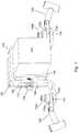
- Bracket assembly 100secured to cross-arm 300 in accordance with the principles disclosed herein.
- Bracket assembly 100comprises bracket 102 , adjustable plate 104 , first accessory frame 106 , and second accessory frame 108 .
- bracket 102is generally U-shaped and positioned over cross-arm 300 .
- adjustable plate 104is generally L-shaped.
- bracket 102 and adjustable plate 104facilitate securing bracket assembly 100 to cross-arm 300 and cross-arm 400 .
- bracket 102 and adjustable plate 104facilitate securing bracket assembly 100 to cross-arm 300 and cross-arm 400 .
- bracket 102 and adjustable plate 104can be utilized for bracket 102 and adjustable plate 104 to secure bracket assembly 100 to cross-arm 300 and cross-arm 400 , without departing from the principles disclosed herein.
- first accessory frame 106is coupled to bracket 102 utilizing first accessory frame fastener 110 .
- An electrical accessorysuch as a lightning arrester, fuse cut-outs, or disconnect switch can be coupled to first accessory frame 106 .
- First accessory frame fastener 110comprises bolt 112 a and captive nut 118 a .
- captive nut 118 ais coupled to bolt 112 a utilizing captive lock 120 a .
- second accessory frame 108is coupled to bracket 102 utilizing second accessory frame fastener 134 .
- an electrical accessorysuch as a lightning arrester, fuse cut-outs, or disconnect switch can be coupled to second accessory frame 108 .
- Second accessory frame fastener 134comprises bolt 112 b and captive nut 118 b .
- Captive nut 118 bis coupled to bolt 112 b utilizing captive lock 120 b.
- Bracket assembly 100further comprises first guide pin 122 , second guide pin 124 , adjustable plate bolt 126 , and moveable spacer 136 .
- Moveable spacer 136is configured to reduce the excessive deformation of bracket 102 when adjustable plate bolt 126 is threadably inserted to secure an adjustable plate to a cross-arm. As shown in FIG. 1 , the thickness of moveable spacer 136 limits the distance that adjustable plate bolt 126 can be threadably inserted to secure adjustable plate 104 , thereby reducing the potential for failure deformation of bracket 102 . Further, moveable spacer 136 is configured to prevent adjustable plate bolt 126 from threadably inserting when adjustable plate 104 is secured to cross-arm 300 .
- an operatoris provided an indicator that a bracket assembly is properly secured to cross-arm 300 .
- the adjustable plate bolt, guide pins, and spacerare designed to properly secure adjustable plate 104 to cross-arm 300 .
- One of ordinary skill in the artwill readily recognize that other methods for aligning and securing the adjustable plate to a cross-arm can be utilized without departing from the principles disclosed herein.
- the width of cross-arm 400is less than the width of cross-arm 300 shown in FIG. 1 .
- moveable spacer 136has been positioned on bracket 102 such that it does not limit the distance that adjustable plate bolt 126 can be threadably inserted to secure adjustable plate 104 to cross-arm 400 .
- moveable spacer 136remains secured to bracket 102 , such that its position can be adjusted on ground level or when the utility personnel is on top of a utility pole without becoming loose from bracket 102 .
- An exemplary method of securing a moveable spacer to a bracketutilizes guides that are generally c channel shaped. The guides include enough clearance to allow the moveable spacer to move along and remain secure to the bracket.
- guidesinclude enough clearance to allow the moveable spacer to move along and remain secure to the bracket.
- FIG. 3shown is a step of a process of securing bracket assembly 100 to a cross-arm in accordance with the principles disclosed herein.
- First accessory frame 106 and second accessory frame 108are coupled to bracket 102 utilizing first accessory frame fastener 110 and second accessory frame fastener 134 , respectively.
- bolt 112 a of first accessory frame fastener 110is inserted into an opening in bracket 102 .
- Bolt 112 acomprises bolt head 114 a and threaded portion 116 a .
- the diameter of bolt head 114 ais greater than the diameter of the opening in bracket 102 that threaded portion 116 a of bolt 112 a is inserted through.
- first accessory frame 106is coupled to bolt 112 a by inserting threaded portion 116 a through an opening in first accessory frame 106 .
- captive nut 118 ais threadably coupled to threaded portion 116 a of bolt 112 a to secure first accessory frame 106 to bracket 102 .
- Captive nut 118 ais configured to prevent first accessory frame 106 and bolt 112 a from becoming loose during the assembly of bracket assembly 100 to a cross-arm.
- Captive nut 118 acomprises captive lock 120 a which is configured to secure to threaded portion 116 a .
- captive nut 118 a and captive lock 120 aare integral.
- An exemplary captive lockcomprises a nylon insert located in a tapered section.
- the nylon insertcan comprise an inner diameter that is slightly smaller than the diameter of a threaded portion of the bolt. Therefore, the nylon insert deforms over the threads of the threaded portion as the captive nut is threadably coupled to the threaded portion.
- bolt 112 b of second accessory frame fastener 134is inserted into an opening in bracket 102 .
- first accessory frame fastener 110can be modified without departing from the principles disclosed herein (i.e., in FIG. 3 , the opening for second accessory frame fastener 134 allowing for the insertion into bracket 102 is shown opposite from the opening for first accessory frame fastener 110 allowing for the insertion into bracket 102 ).
- Bolt 112 bcomprises bolt head 114 b and threaded portion 116 b . As shown in FIG.
- the diameter of bolt head 114 bis greater than the diameter of the opening in bracket 102 that threaded portion 116 b of bolt 112 b is inserted through.
- second accessory frame 108is coupled to bolt 112 b by inserting threaded portion 116 b through an opening in second accessory frame 108 .
- captive nut 118 bis threadably coupled to threaded portion 116 b of bolt 112 b to secure second accessory frame 108 to bracket 102 .
- Captive nut 118 bis configured to prevent second accessory frame 108 and bolt 112 b from becoming loose during the assembly of bracket assembly 100 to a cross-arm.
- Captive nut 118 bcomprises captive lock 120 b which is configured to secure to threaded portion 116 b . As shown in FIG. 3 , captive nut 118 b and captive lock 120 b are integral. The process of securing the first accessory frame and the second accessory frame can be performed on ground level without the need for protective equipment as the system is not energized and the work is not performed in close proximity to energized components.
- adjustable plate 104is removably coupled to bracket 102 with first guide pin 122 , second guide pin 124 , and adjustable plate bolt 126 .
- Adjustable plate bolt 126comprises head 128 , locking device 130 , and threaded portion 132 .
- Threaded portion 132 of adjustable plate bolt 126is threadably inserted into an opening of bracket 102 .
- An end of threaded portion 132is coupled to adjustable plate 104 , such that adjustable plate 104 moves parallel to the direction of threaded portion 132 threadably inserted into an opening of bracket 102 .
- First guide pin 122 and second guide pin 124are coupled to adjustable plate 104 and inserted into an opening in bracket 102 .
- moveable spacer 136has been positioned on bracket 102 such that it does not limit the distance that adjustable plate bolt 126 can be threadably inserted to secure adjustable plate 104 to a cross-arm.
- adjustable plate bolt 126can be threadably inserted to secure adjustable plate 104 to a cross-arm.
- the process of coupling the adjustable plate to the bracketcan be performed on ground level without the need for protective equipment.
- bracket assembly 100is shown positioned on cross-arm 400 .
- the process of securing bracket assembly 100 to cross-arm 400involves turning head 128 of adjustable plate bolt 126 .
- head 128is turned clockwise, threaded portion 132 of adjustable plate bolt 126 threadably inserts into an opening in bracket 102 and moves adjustable plate 104 towards cross-arm 400 .
- Locking device 130is configured to prevent adjustable plate bolt 126 from loosening once adjustable plate 104 is secured to a cross-arm.
- An exemplary locking devicecan comprise a flat washer and split lock washer. Turning head 128 in a counterclockwise direction threadably removes threaded portion 132 from an opening in bracket 102 and moves adjustable plate 104 away from cross-arm 400 .
- FIG. 5depicts bracket assembly 100 secured to cross-arm 300 .
- Moveable spacer 136has been positioned to limit the distance that adjustable plate bolt 126 can be threadably inserted to secure adjustable plate 104 to cross-arm 300 .
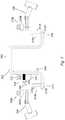
- Bracket assembly 200secured to cross-arm 500 in accordance with the principles disclosed herein.
- Bracket assembly 200comprises bracket 202 , adjustable plate 204 , first accessory frame 206 , and second accessory frame 208 .
- bracket 202is generally U-shaped and positioned over cross-arm 500 .
- adjustable plate 204is generally L-shaped.
- bracket 202 and adjustable plate 204facilitate securing bracket assembly 200 to cross-arm 500 .
- bracket 202 and adjustable plate 204facilitate securing bracket assembly 200 to cross-arm 500 .
- bracket 202 and adjustable plate 204can be utilized for bracket 202 and adjustable plate 204 to secure bracket assembly 200 to cross-arm 500 , without departing from the principles disclosed herein.
- first accessory frame 206is coupled to bracket 202 utilizing first accessory frame fastener 210 .
- An electrical accessorysuch as a lightning arrester, fuse cut-outs, or disconnect switch can be coupled to first accessory frame 206 .
- First accessory frame fastener 210comprises bolt 212 a and captive nut 218 a .
- captive nut 218 ais coupled to bolt 212 a utilizing captive lock 220 a .
- second accessory frame 208is coupled to bracket 202 utilizing second accessory frame fastener 234 .
- Second accessory frame fastener 234comprises bolt 212 b and captive nut 218 b .
- Captive nut 218 bcomprises captive lock 220 b.
- Bracket assembly 200further comprises first guide pin 222 , second guide pin 224 , and adjustable plate bolt 226 .
- the adjustable plate bolt and guide pinsare designed to properly secure adjustable plate 204 to cross-arm 500 .
- One of ordinary skill in the artwill readily recognize that other methods for aligning and securing the adjustable plate to a cross-arm can be utilized without departing from the principles disclosed herein.
- first accessory frame 206 and second accessory frame 208are coupled to bracket 202 utilizing first accessory frame fastener 210 and second accessory frame fastener 234 , respectively.
- bolt 212 a of first accessory frame fastener 210is inserted into an opening in bracket 202 .
- Bolt 212 acomprises bolt head 214 a and threaded portion 216 a .
- the diameter of bolt head 214 ais greater than the diameter of the opening in bracket 202 that threaded portion 216 a of bolt 212 a is inserted through.
- first accessory frame 206is coupled to bolt 212 a by inserting threaded portion 216 a through an opening in first accessory frame 206 .
- captive nut 218 ais threadably coupled to threaded portion 216 a of bolt 212 a to secure first accessory frame 206 to bracket 202 .
- Captive nut 218 ais configured to prevent first accessory frame 206 and bolt 212 a from becoming loose during the assembly of bracket assembly 200 to a cross-arm.
- Captive nut 218 acomprises captive lock 220 a which is configured to secure to threaded portion 216 a .
- captive nut 218 a and captive lock 220 aare integral.
- An exemplary captive lockcomprises a nylon insert located in a tapered section.
- the nylon insertcan comprise an inner diameter that is slightly smaller than the diameter of a threaded portion of the bolt. Therefore, the nylon insert deforms over the threads of the threaded portion as the captive nut is threadably coupled to the threaded portion.
- bolt 212 b of second accessory frame fastener 234is inserted into an opening in bracket 202 .
- first accessory frame fastener 210can be modified without departing from the principles disclosed herein (i.e., in FIG. 7 , the opening for second accessory frame fastener 234 allowing for the insertion into bracket 102 is shown opposite from the opening for first accessory frame fastener 210 allowing for the insertion into bracket 202 ).
- Bolt 212 bcomprises bolt head 214 b and threaded portion 216 b . As shown in FIG.
- the diameter of bolt head 214 bis greater than the diameter of the opening in bracket 202 that threaded portion 216 b of bolt 212 b is inserted through.
- second accessory frame 208is coupled to bolt 212 b by inserting threaded portion 216 b through an opening in second accessory frame 208 .
- captive nut 218 bis threadably coupled to threaded portion 216 b of bolt 212 b to secure second accessory frame 208 to bracket 202 .
- Captive nut 218 bis configured to prevent second accessory frame 208 and bolt 212 b from becoming loose during the assembly of bracket assembly 200 to a cross-arm.
- Captive nut 218 bcomprises captive lock 220 b which is configured to secure to threaded portion 216 b . As shown in FIG. 7 , for exemplary purposes, captive nut 218 b and captive lock 220 b are integral. The process of securing the first accessory frame and second accessory frame can be performed on ground level without the need for protective equipment.
- adjustable plate 204is removably coupled to bracket 202 with first guide pin 222 , second guide pin 224 , and adjustable plate bolt 226 .
- Adjustable plate bolt 226comprises shear head 228 , head 230 , and threaded portion 232 .
- Threaded portion 232 of adjustable plate bolt 226is threadably inserted into an opening of bracket 202 .
- An end of threaded portion 232is coupled to adjustable plate 204 , such that adjustable plate 204 moves parallel to the length of threaded portion 232 when it is threadably inserted into an opening of bracket 202 .
- First guide pin 222 and second guide pin 224are coupled to adjustable plate 204 and inserted into an opening in bracket 202 .
- the process of coupling the adjustable plate to the bracketcan be performed on ground level without the need for protective equipment.
- bracket assembly 200is shown positioned on cross-arm 500 .
- the process of securing bracket assembly 200 to cross-arm 500involves turning shear head 228 of adjustable plate bolt 226 .
- threaded portion 232 of adjustable plate bolt 226threadably inserts into an opening in bracket 202 and moves adjustable plate 204 towards cross-arm 500 .
- Turning shear head 228 in a counterclockwise directionthreadably removes threaded portion 232 from an opening in bracket 202 and moves adjustable plate 204 away from cross-arm 500 .
- the shear head(not shown) is configured to shear from adjustable plate bolt 226 when the adequate torque for securing bracket assembly 200 to cross-arm 500 has been obtained.
- An exemplary torqueis 15-20 ft-lbs.
- head 230 of adjustable plate bolt 226can be utilized to unsecure bracket assembly 200 from cross-arm 500 .
Landscapes
- Engineering & Computer Science (AREA)
- Architecture (AREA)
- Civil Engineering (AREA)
- Structural Engineering (AREA)
- Connection Of Plates (AREA)
Abstract
Description
Claims (19)
Priority Applications (1)
| Application Number | Priority Date | Filing Date | Title |
|---|---|---|---|
| US16/266,057US11174654B2 (en) | 2018-02-02 | 2019-02-02 | Overhead electrical accessory bracket |
Applications Claiming Priority (2)
| Application Number | Priority Date | Filing Date | Title |
|---|---|---|---|
| US201862625898P | 2018-02-02 | 2018-02-02 | |
| US16/266,057US11174654B2 (en) | 2018-02-02 | 2019-02-02 | Overhead electrical accessory bracket |
Publications (2)
| Publication Number | Publication Date |
|---|---|
| US20190242150A1 US20190242150A1 (en) | 2019-08-08 |
| US11174654B2true US11174654B2 (en) | 2021-11-16 |
Family
ID=67475089
Family Applications (1)
| Application Number | Title | Priority Date | Filing Date |
|---|---|---|---|
| US16/266,057Active2039-11-14US11174654B2 (en) | 2018-02-02 | 2019-02-02 | Overhead electrical accessory bracket |
Country Status (1)
| Country | Link |
|---|---|
| US (1) | US11174654B2 (en) |
Citations (23)
| Publication number | Priority date | Publication date | Assignee | Title |
|---|---|---|---|---|
| US882835A (en)* | 1907-01-21 | 1908-03-24 | John E Mcgillivray | Device for attaching cross-arms to telegraph-poles. |
| US2721362A (en)* | 1949-08-24 | 1955-10-25 | Gen Electric | Transmission line support |
| US2728462A (en)* | 1952-11-17 | 1955-12-27 | Harry L Fincher | Wire lift |
| US3129917A (en)* | 1962-11-27 | 1964-04-21 | Malleable Iron Fittings Co | Support for an aerial cable suspension clamp |
| US3369788A (en)* | 1966-01-24 | 1968-02-20 | Albert C. Eisele | Utility pole mounting bracket for electrical safety devices |
| US3428283A (en)* | 1967-09-11 | 1969-02-18 | Joslyn Mfg & Supply Co | Adjustable spacer assembly |
| US3445582A (en)* | 1966-09-29 | 1969-05-20 | Pacific Gas & Electric Co | Pole top mounting bracket for electrical transmission line |
| US3474995A (en)* | 1967-06-23 | 1969-10-28 | Joseph C Amidon | Utility pole insulator bracket extension |
| US3499973A (en)* | 1968-07-11 | 1970-03-10 | Lexalite Corp | Support bracket for standoff insulators and the like |
| US3568968A (en)* | 1969-04-16 | 1971-03-09 | Mif Ind Inc | Utility wire supporting bracket |
| US3772179A (en)* | 1971-03-17 | 1973-11-13 | E Beer | Cathodic protection device |
| US3856250A (en)* | 1970-12-09 | 1974-12-24 | Aluma Form Inc | Interengaged component electrical equipment mount |
| US4127739A (en)* | 1977-02-10 | 1978-11-28 | Aluma-Form Inc. | Level mount electrical component bracket |
| US4932623A (en)* | 1988-05-06 | 1990-06-12 | Hughes Brothers, Inc. | Bracket |
| US5174535A (en)* | 1989-05-18 | 1992-12-29 | Vanbrace Pty. Ltd. | Cross-arm mounting bracket for poles |
| US5426577A (en)* | 1993-02-23 | 1995-06-20 | Musco Corporation | Pole-mounted lighting system |
| US5445348A (en)* | 1994-09-12 | 1995-08-29 | Reliable Bethea Power Products, Inc. | Auxiliary cable attachment |
| US6936779B2 (en)* | 2003-08-28 | 2005-08-30 | Hubbell Incorporated | Bypass recloser assembly |
| US7216850B2 (en)* | 2001-06-11 | 2007-05-15 | Daewon Electric Co. Ltd. | Electric wire changing device for wire replacing works on electric poles and power distributing method without cutting off power supply |
| US8919584B2 (en)* | 2011-04-11 | 2014-12-30 | Abb Technology Ag | Electrical equipment mounting frame |
| US20150075859A1 (en)* | 2013-09-17 | 2015-03-19 | San Diego Gas & Electric Company | Cross arm covers for utility poles and related methods |
| US20150263501A1 (en)* | 2014-03-12 | 2015-09-17 | Carddine, Llc | Installation guard for overhead utility lines |
| US9231394B2 (en)* | 2009-12-11 | 2016-01-05 | British Columbia Hydro And Power Authority | Cementitious fibre reinforced composite cross arm |
- 2019
- 2019-02-02USUS16/266,057patent/US11174654B2/enactiveActive
Patent Citations (24)
| Publication number | Priority date | Publication date | Assignee | Title |
|---|---|---|---|---|
| US882835A (en)* | 1907-01-21 | 1908-03-24 | John E Mcgillivray | Device for attaching cross-arms to telegraph-poles. |
| US2721362A (en)* | 1949-08-24 | 1955-10-25 | Gen Electric | Transmission line support |
| US2728462A (en)* | 1952-11-17 | 1955-12-27 | Harry L Fincher | Wire lift |
| US3129917A (en)* | 1962-11-27 | 1964-04-21 | Malleable Iron Fittings Co | Support for an aerial cable suspension clamp |
| US3369788A (en)* | 1966-01-24 | 1968-02-20 | Albert C. Eisele | Utility pole mounting bracket for electrical safety devices |
| US3445582A (en)* | 1966-09-29 | 1969-05-20 | Pacific Gas & Electric Co | Pole top mounting bracket for electrical transmission line |
| US3474995A (en)* | 1967-06-23 | 1969-10-28 | Joseph C Amidon | Utility pole insulator bracket extension |
| US3428283A (en)* | 1967-09-11 | 1969-02-18 | Joslyn Mfg & Supply Co | Adjustable spacer assembly |
| US3499973A (en)* | 1968-07-11 | 1970-03-10 | Lexalite Corp | Support bracket for standoff insulators and the like |
| US3568968A (en)* | 1969-04-16 | 1971-03-09 | Mif Ind Inc | Utility wire supporting bracket |
| US3856250A (en)* | 1970-12-09 | 1974-12-24 | Aluma Form Inc | Interengaged component electrical equipment mount |
| US3772179A (en)* | 1971-03-17 | 1973-11-13 | E Beer | Cathodic protection device |
| US4127739A (en)* | 1977-02-10 | 1978-11-28 | Aluma-Form Inc. | Level mount electrical component bracket |
| US4932623A (en)* | 1988-05-06 | 1990-06-12 | Hughes Brothers, Inc. | Bracket |
| US5174535A (en)* | 1989-05-18 | 1992-12-29 | Vanbrace Pty. Ltd. | Cross-arm mounting bracket for poles |
| US5426577A (en)* | 1993-02-23 | 1995-06-20 | Musco Corporation | Pole-mounted lighting system |
| US5445348A (en)* | 1994-09-12 | 1995-08-29 | Reliable Bethea Power Products, Inc. | Auxiliary cable attachment |
| US7216850B2 (en)* | 2001-06-11 | 2007-05-15 | Daewon Electric Co. Ltd. | Electric wire changing device for wire replacing works on electric poles and power distributing method without cutting off power supply |
| US7387294B2 (en)* | 2001-06-11 | 2008-06-17 | Daewon Electric Co., Ltd | Electric wire changing device for wire replacing works on electric poles and power distributing method without cutting off power supply |
| US6936779B2 (en)* | 2003-08-28 | 2005-08-30 | Hubbell Incorporated | Bypass recloser assembly |
| US9231394B2 (en)* | 2009-12-11 | 2016-01-05 | British Columbia Hydro And Power Authority | Cementitious fibre reinforced composite cross arm |
| US8919584B2 (en)* | 2011-04-11 | 2014-12-30 | Abb Technology Ag | Electrical equipment mounting frame |
| US20150075859A1 (en)* | 2013-09-17 | 2015-03-19 | San Diego Gas & Electric Company | Cross arm covers for utility poles and related methods |
| US20150263501A1 (en)* | 2014-03-12 | 2015-09-17 | Carddine, Llc | Installation guard for overhead utility lines |
Also Published As
| Publication number | Publication date |
|---|---|
| US20190242150A1 (en) | 2019-08-08 |
Similar Documents
| Publication | Publication Date | Title |
|---|---|---|
| US20210288476A1 (en) | Lockout tagout assembly and system and method of using same | |
| US9742350B2 (en) | Solar panel grounding lug assemblies and systems | |
| EP1626470A2 (en) | Current distribution system for electric supply of rail-mounted installations in an aircraft | |
| US4904193A (en) | Electrical grounding clamp | |
| US20160016666A1 (en) | Modular Mounting Structure with Embedded Electrical Bus | |
| EP2154701B1 (en) | Installation device with protective device | |
| CN105356368B (en) | Insulating shield installation tool | |
| US11174654B2 (en) | Overhead electrical accessory bracket | |
| US20100155212A1 (en) | Isolating apparatus for electric power lines and methods for forming and using the same | |
| CN103681142B (en) | A kind of Rink insulation partition | |
| KR102027945B1 (en) | Grounding wire bracket and grounding method using it | |
| CN205123131U (en) | Insulating guard shield mounting tool | |
| CN207572433U (en) | Electrical box installation mechanism and electrical box system | |
| CN220984448U (en) | Secondary fusion standardized on-column circuit breaker | |
| KR100834860B1 (en) | Enclosure for cockle-mounted electronic device | |
| CN117038383A (en) | Outdoor high-voltage vacuum circuit breaker | |
| KR20190000956U (en) | conneting unit for clamp and insulator | |
| US8046888B2 (en) | Yoke assembly and method of installing same | |
| US9083092B2 (en) | Electrical connections for high voltage electrical distribution and/or reticulation | |
| DE102017223812B4 (en) | Electrical high-current connection with simplified assembly | |
| CN223378616U (en) | Lightning protection grounding integrated device for power engineering | |
| CN118832551B (en) | Spring pin installation tool and spring pin installation method | |
| CN110778889A (en) | Adjustable support and adjustable fixing device of communication equipment | |
| CN219685413U (en) | Mounting device applied to opening elastic sealing ring | |
| US20180079061A1 (en) | Locking terminal clamp cable assembly |
Legal Events
| Date | Code | Title | Description |
|---|---|---|---|
| FEPP | Fee payment procedure | Free format text:ENTITY STATUS SET TO UNDISCOUNTED (ORIGINAL EVENT CODE: BIG.); ENTITY STATUS OF PATENT OWNER: SMALL ENTITY | |
| FEPP | Fee payment procedure | Free format text:ENTITY STATUS SET TO SMALL (ORIGINAL EVENT CODE: SMAL); ENTITY STATUS OF PATENT OWNER: SMALL ENTITY | |
| STPP | Information on status: patent application and granting procedure in general | Free format text:DOCKETED NEW CASE - READY FOR EXAMINATION | |
| STPP | Information on status: patent application and granting procedure in general | Free format text:NON FINAL ACTION MAILED | |
| STPP | Information on status: patent application and granting procedure in general | Free format text:RESPONSE TO NON-FINAL OFFICE ACTION ENTERED AND FORWARDED TO EXAMINER | |
| STPP | Information on status: patent application and granting procedure in general | Free format text:FINAL REJECTION MAILED | |
| AS | Assignment | Owner name:RICHARDS MANUFACTURING COMPANY, LP, NEW JERSEY Free format text:ASSIGNMENT OF ASSIGNORS INTEREST;ASSIGNORS:JUILLET, CHRISTOPHER;FOX, RICHARD;BIER, JOSEPH;REEL/FRAME:056682/0205 Effective date:20210616 | |
| STPP | Information on status: patent application and granting procedure in general | Free format text:RESPONSE AFTER FINAL ACTION FORWARDED TO EXAMINER | |
| STPP | Information on status: patent application and granting procedure in general | Free format text:NOTICE OF ALLOWANCE MAILED -- APPLICATION RECEIVED IN OFFICE OF PUBLICATIONS | |
| AS | Assignment | Owner name:RICHARDS MANUFACTURING COMPANY, A NEW JERSEY LIMITED PARTNERSHIP, NEW JERSEY Free format text:CORRECTIVE ASSIGNMENT TO CORRECT THE RECEIVING PARTY NAME PREVIOUSLY RECORDED AT REEL: 056682 FRAME: 0205. ASSIGNOR(S) HEREBY CONFIRMS THE ASSIGNMENT;ASSIGNORS:JUILLET, CHRISTOPHER;FOX, RICHARD;BIER, JOSEPH;SIGNING DATES FROM 20210616 TO 20210617;REEL/FRAME:057246/0990 | |
| STPP | Information on status: patent application and granting procedure in general | Free format text:PUBLICATIONS -- ISSUE FEE PAYMENT VERIFIED | |
| STCF | Information on status: patent grant | Free format text:PATENTED CASE | |
| AS | Assignment | Owner name:RICHARDS MFG. CO., A NEW JERSEY LIMITED PARTNERSHIP, NEW JERSEY Free format text:CORRECTIVE ASSIGNMENT TO CORRECT THE ASSIGNEE NAME PREVIOUSLY RECORDED ON REEL 057246 FRAME 0990. ASSIGNOR(S) HEREBY CONFIRMS THE ASSIGNMENT TO RICHARDS MFG. CO., A NEW JERSEY LIMITED PARTNERSHIP;ASSIGNORS:JUILLET, CHRISTOPHER;FOX, RICHARD;BIER, JOSEPH;SIGNING DATES FROM 20211122 TO 20211124;REEL/FRAME:058608/0137 | |
| AS | Assignment | Owner name:CAPITAL ONE, NATIONAL ASSOCIATION, AS COLLATERAL AGENT, NEW YORK Free format text:SECURITY INTEREST;ASSIGNORS:ELECTRONIC TECHNOLOGY, LLC;RICHARDS MFG. CO. SALES, LLC;RICHARDS MFG. CO., A NEW JERSEY LIMITED PARTNERSHIP;REEL/FRAME:064356/0552 Effective date:20230721 | |
| AS | Assignment | Owner name:RICHARDS MFG. CO. SALES, LLC, NEW JERSEY Free format text:MERGER AND CHANGE OF NAME;ASSIGNOR:RICHARDS MFG. CO., A NEW JERSEY LIMITED PARTNERSHIP;REEL/FRAME:069647/0166 Effective date:20231229 | |
| AS | Assignment | Owner name:RICHARDS MFG. CO., A NEW JERSEY LIMITED PARTNERSHIP, NEW JERSEY Free format text:RELEASE BY SECURED PARTY;ASSIGNOR:CAPITAL ONE, NATIONAL ASSOCIATION, AS AGENT;REEL/FRAME:070703/0807 Effective date:20250401 Owner name:RICHARDS MFG. CO. SALES, LLC, NEW JERSEY Free format text:RELEASE BY SECURED PARTY;ASSIGNOR:CAPITAL ONE, NATIONAL ASSOCIATION, AS AGENT;REEL/FRAME:070703/0807 Effective date:20250401 Owner name:ELECTRONIC TECHNOLOGY, LLC, NEW JERSEY Free format text:RELEASE BY SECURED PARTY;ASSIGNOR:CAPITAL ONE, NATIONAL ASSOCIATION, AS AGENT;REEL/FRAME:070703/0807 Effective date:20250401 | |
| MAFP | Maintenance fee payment | Free format text:PAYMENT OF MAINTENANCE FEE, 4TH YR, SMALL ENTITY (ORIGINAL EVENT CODE: M2551); ENTITY STATUS OF PATENT OWNER: SMALL ENTITY Year of fee payment:4 |