US11173629B2 - Continuous mixer and method of mixing reinforcing fibers with cementitious materials - Google Patents
Continuous mixer and method of mixing reinforcing fibers with cementitious materialsDownload PDFInfo
- Publication number
- US11173629B2 US11173629B2US15/662,932US201715662932AUS11173629B2US 11173629 B2US11173629 B2US 11173629B2US 201715662932 AUS201715662932 AUS 201715662932AUS 11173629 B2US11173629 B2US 11173629B2
- Authority
- US
- United States
- Prior art keywords
- slurry
- fiber
- mixer
- cementitious
- horizontal
- Prior art date
- Legal status (The legal status is an assumption and is not a legal conclusion. Google has not performed a legal analysis and makes no representation as to the accuracy of the status listed.)
- Active, expires
Links
Images


Classifications
- B01F13/1027—
- B—PERFORMING OPERATIONS; TRANSPORTING
- B01—PHYSICAL OR CHEMICAL PROCESSES OR APPARATUS IN GENERAL
- B01F—MIXING, e.g. DISSOLVING, EMULSIFYING OR DISPERSING
- B01F23/00—Mixing according to the phases to be mixed, e.g. dispersing or emulsifying
- B01F23/50—Mixing liquids with solids
- B01F23/53—Mixing liquids with solids using driven stirrers
- B—PERFORMING OPERATIONS; TRANSPORTING
- B01—PHYSICAL OR CHEMICAL PROCESSES OR APPARATUS IN GENERAL
- B01F—MIXING, e.g. DISSOLVING, EMULSIFYING OR DISPERSING
- B01F27/00—Mixers with rotary stirring devices in fixed receptacles; Kneaders
- B01F27/05—Stirrers
- B01F27/07—Stirrers characterised by their mounting on the shaft
- B01F27/071—Fixing of the stirrer to the shaft
- B—PERFORMING OPERATIONS; TRANSPORTING
- B01—PHYSICAL OR CHEMICAL PROCESSES OR APPARATUS IN GENERAL
- B01F—MIXING, e.g. DISSOLVING, EMULSIFYING OR DISPERSING
- B01F27/00—Mixers with rotary stirring devices in fixed receptacles; Kneaders
- B01F27/05—Stirrers
- B01F27/07—Stirrers characterised by their mounting on the shaft
- B01F27/072—Stirrers characterised by their mounting on the shaft characterised by the disposition of the stirrers with respect to the rotating axis
- B01F27/0726—Stirrers characterised by their mounting on the shaft characterised by the disposition of the stirrers with respect to the rotating axis having stirring elements connected to the stirrer shaft each by a single radial rod, other than open frameworks
- B—PERFORMING OPERATIONS; TRANSPORTING
- B01—PHYSICAL OR CHEMICAL PROCESSES OR APPARATUS IN GENERAL
- B01F—MIXING, e.g. DISSOLVING, EMULSIFYING OR DISPERSING
- B01F27/00—Mixers with rotary stirring devices in fixed receptacles; Kneaders
- B01F27/60—Mixers with rotary stirring devices in fixed receptacles; Kneaders with stirrers rotating about a horizontal or inclined axis
- B01F27/70—Mixers with rotary stirring devices in fixed receptacles; Kneaders with stirrers rotating about a horizontal or inclined axis with paddles, blades or arms
- B01F27/707—Mixers with rotary stirring devices in fixed receptacles; Kneaders with stirrers rotating about a horizontal or inclined axis with paddles, blades or arms the paddles co-operating, e.g. intermeshing, with elements on the receptacle wall
- B—PERFORMING OPERATIONS; TRANSPORTING
- B01—PHYSICAL OR CHEMICAL PROCESSES OR APPARATUS IN GENERAL
- B01F—MIXING, e.g. DISSOLVING, EMULSIFYING OR DISPERSING
- B01F33/00—Other mixers; Mixing plants; Combinations of mixers
- B01F33/80—Mixing plants; Combinations of mixers
- B01F33/82—Combinations of dissimilar mixers
- B01F33/821—Combinations of dissimilar mixers with consecutive receptacles
- B—PERFORMING OPERATIONS; TRANSPORTING
- B01—PHYSICAL OR CHEMICAL PROCESSES OR APPARATUS IN GENERAL
- B01F—MIXING, e.g. DISSOLVING, EMULSIFYING OR DISPERSING
- B01F33/00—Other mixers; Mixing plants; Combinations of mixers
- B01F33/80—Mixing plants; Combinations of mixers
- B01F33/834—Mixing in several steps, e.g. successive steps
- B—PERFORMING OPERATIONS; TRANSPORTING
- B01—PHYSICAL OR CHEMICAL PROCESSES OR APPARATUS IN GENERAL
- B01F—MIXING, e.g. DISSOLVING, EMULSIFYING OR DISPERSING
- B01F35/00—Accessories for mixers; Auxiliary operations or auxiliary devices; Parts or details of general application
- B01F35/71—Feed mechanisms
- B01F35/715—Feeding the components in several steps, e.g. successive steps
- B01F7/001—
- B01F7/00158—
- B01F7/04—
- B—PERFORMING OPERATIONS; TRANSPORTING
- B28—WORKING CEMENT, CLAY, OR STONE
- B28B—SHAPING CLAY OR OTHER CERAMIC COMPOSITIONS; SHAPING SLAG; SHAPING MIXTURES CONTAINING CEMENTITIOUS MATERIAL, e.g. PLASTER
- B28B1/00—Producing shaped prefabricated articles from the material
- B28B1/52—Producing shaped prefabricated articles from the material specially adapted for producing articles from mixtures containing fibres, e.g. asbestos cement
- B28B1/522—Producing shaped prefabricated articles from the material specially adapted for producing articles from mixtures containing fibres, e.g. asbestos cement for producing multi-layered articles
- B—PERFORMING OPERATIONS; TRANSPORTING
- B28—WORKING CEMENT, CLAY, OR STONE
- B28B—SHAPING CLAY OR OTHER CERAMIC COMPOSITIONS; SHAPING SLAG; SHAPING MIXTURES CONTAINING CEMENTITIOUS MATERIAL, e.g. PLASTER
- B28B13/00—Feeding the unshaped material to moulds or apparatus for producing shaped articles; Discharging shaped articles from such moulds or apparatus
- B28B13/02—Feeding the unshaped material to moulds or apparatus for producing shaped articles
- B28B13/0215—Feeding the moulding material in measured quantities from a container or silo
- B28B13/0275—Feeding a slurry or a ceramic slip
- B—PERFORMING OPERATIONS; TRANSPORTING
- B28—WORKING CEMENT, CLAY, OR STONE
- B28B—SHAPING CLAY OR OTHER CERAMIC COMPOSITIONS; SHAPING SLAG; SHAPING MIXTURES CONTAINING CEMENTITIOUS MATERIAL, e.g. PLASTER
- B28B19/00—Machines or methods for applying the material to surfaces to form a permanent layer thereon
- B28B19/0092—Machines or methods for applying the material to surfaces to form a permanent layer thereon to webs, sheets or the like, e.g. of paper, cardboard
- B—PERFORMING OPERATIONS; TRANSPORTING
- B28—WORKING CEMENT, CLAY, OR STONE
- B28C—PREPARING CLAY; PRODUCING MIXTURES CONTAINING CLAY OR CEMENTITIOUS MATERIAL, e.g. PLASTER
- B28C5/00—Apparatus or methods for producing mixtures of cement with other substances, e.g. slurries, mortars, porous or fibrous compositions
- B28C5/08—Apparatus or methods for producing mixtures of cement with other substances, e.g. slurries, mortars, porous or fibrous compositions using driven mechanical means affecting the mixing
- B28C5/10—Mixing in containers not actuated to effect the mixing
- B28C5/12—Mixing in containers not actuated to effect the mixing with stirrers sweeping through the materials, e.g. with incorporated feeding or discharging means or with oscillating stirrers
- B28C5/1238—Mixing in containers not actuated to effect the mixing with stirrers sweeping through the materials, e.g. with incorporated feeding or discharging means or with oscillating stirrers for materials flowing continuously through the mixing device and with incorporated feeding or discharging devices
- B28C5/1276—Mixing in containers not actuated to effect the mixing with stirrers sweeping through the materials, e.g. with incorporated feeding or discharging means or with oscillating stirrers for materials flowing continuously through the mixing device and with incorporated feeding or discharging devices with consecutive separate containers with rotating stirring and feeding or discharging means
- B28C5/1284—Mixing in containers not actuated to effect the mixing with stirrers sweeping through the materials, e.g. with incorporated feeding or discharging means or with oscillating stirrers for materials flowing continuously through the mixing device and with incorporated feeding or discharging devices with consecutive separate containers with rotating stirring and feeding or discharging means having a feeding hopper and consecutive vertical or inclined mixing container fed at its upper part
- B—PERFORMING OPERATIONS; TRANSPORTING
- B28—WORKING CEMENT, CLAY, OR STONE
- B28C—PREPARING CLAY; PRODUCING MIXTURES CONTAINING CLAY OR CEMENTITIOUS MATERIAL, e.g. PLASTER
- B28C5/00—Apparatus or methods for producing mixtures of cement with other substances, e.g. slurries, mortars, porous or fibrous compositions
- B28C5/08—Apparatus or methods for producing mixtures of cement with other substances, e.g. slurries, mortars, porous or fibrous compositions using driven mechanical means affecting the mixing
- B28C5/10—Mixing in containers not actuated to effect the mixing
- B28C5/12—Mixing in containers not actuated to effect the mixing with stirrers sweeping through the materials, e.g. with incorporated feeding or discharging means or with oscillating stirrers
- B28C5/14—Mixing in containers not actuated to effect the mixing with stirrers sweeping through the materials, e.g. with incorporated feeding or discharging means or with oscillating stirrers the stirrers having motion about a horizontal or substantially horizontal axis
- B28C5/148—Mixing in containers not actuated to effect the mixing with stirrers sweeping through the materials, e.g. with incorporated feeding or discharging means or with oscillating stirrers the stirrers having motion about a horizontal or substantially horizontal axis the stirrer shaft carrying a plurality of radially extending mixing bars
- B—PERFORMING OPERATIONS; TRANSPORTING
- B28—WORKING CEMENT, CLAY, OR STONE
- B28C—PREPARING CLAY; PRODUCING MIXTURES CONTAINING CLAY OR CEMENTITIOUS MATERIAL, e.g. PLASTER
- B28C5/00—Apparatus or methods for producing mixtures of cement with other substances, e.g. slurries, mortars, porous or fibrous compositions
- B28C5/40—Mixing specially adapted for preparing mixtures containing fibres
- B28C5/402—Methods
- B—PERFORMING OPERATIONS; TRANSPORTING
- B28—WORKING CEMENT, CLAY, OR STONE
- B28C—PREPARING CLAY; PRODUCING MIXTURES CONTAINING CLAY OR CEMENTITIOUS MATERIAL, e.g. PLASTER
- B28C7/00—Controlling the operation of apparatus for producing mixtures of clay or cement with other substances; Supplying or proportioning the ingredients for mixing clay or cement with other substances; Discharging the mixture
- B28C7/04—Supplying or proportioning the ingredients
- B28C7/0404—Proportioning
- B28C7/0418—Proportioning control systems therefor
- B—PERFORMING OPERATIONS; TRANSPORTING
- B28—WORKING CEMENT, CLAY, OR STONE
- B28C—PREPARING CLAY; PRODUCING MIXTURES CONTAINING CLAY OR CEMENTITIOUS MATERIAL, e.g. PLASTER
- B28C9/00—General arrangement or layout of plant
- B28C9/002—Mixing systems, i.e. flow charts or diagrams; Making slurries; Involving methodical aspects; Involving pretreatment of ingredients; Involving packaging
- B28C9/004—Making slurries, e.g. with discharging means for injecting in a well or projecting against a wall
- B01F2013/1052—
- B01F2015/0221—
- B01F3/1221—
- B01F7/048—
- B—PERFORMING OPERATIONS; TRANSPORTING
- B05—SPRAYING OR ATOMISING IN GENERAL; APPLYING FLUENT MATERIALS TO SURFACES, IN GENERAL
- B05C—APPARATUS FOR APPLYING FLUENT MATERIALS TO SURFACES, IN GENERAL
- B05C1/00—Apparatus in which liquid or other fluent material is applied to the surface of the work by contact with a member carrying the liquid or other fluent material, e.g. a porous member loaded with a liquid to be applied as a coating
- B05C1/04—Apparatus in which liquid or other fluent material is applied to the surface of the work by contact with a member carrying the liquid or other fluent material, e.g. a porous member loaded with a liquid to be applied as a coating for applying liquid or other fluent material to work of indefinite length
- B05C1/08—Apparatus in which liquid or other fluent material is applied to the surface of the work by contact with a member carrying the liquid or other fluent material, e.g. a porous member loaded with a liquid to be applied as a coating for applying liquid or other fluent material to work of indefinite length using a roller or other rotating member which contacts the work along a generating line
- B05C1/0826—Apparatus in which liquid or other fluent material is applied to the surface of the work by contact with a member carrying the liquid or other fluent material, e.g. a porous member loaded with a liquid to be applied as a coating for applying liquid or other fluent material to work of indefinite length using a roller or other rotating member which contacts the work along a generating line the work being a web or sheets
- B05C1/0834—Apparatus in which liquid or other fluent material is applied to the surface of the work by contact with a member carrying the liquid or other fluent material, e.g. a porous member loaded with a liquid to be applied as a coating for applying liquid or other fluent material to work of indefinite length using a roller or other rotating member which contacts the work along a generating line the work being a web or sheets the coating roller co-operating with other rollers, e.g. dosing, transfer rollers
Definitions
- This applicationis related to:
- This inventiondiscloses a continuous mixer and a method of mixing reinforcing fibers with cementitious materials for producing fiber reinforced cementitious materials in a continuous process.
- U.S. Pat. No. 6,986,812 to Dubey et al.features a slurry feed apparatus for use in a structural cement panel (SCP) production line or the like application where settable slurries are used in the production of building panels or board.
- the apparatusincludes a main metering roll and a companion roll placed in close, generally parallel relationship to each other to form a nip in which a supply of slurry is retained. Both rolls preferably rotate in the same direction so that slurry is drawn from the nip over the metering roll to be deposited upon a moving web of the SCP panel production line.
- a thickness control rollis provided in close operational proximity to the main metering roll for maintaining a desired thickness of the slurry.
- U.S. Pat. No. 7,524,386 B2 to George et aldiscloses a process employing a wet mixer having a vertical mixing chamber for forming a wet slurry of a cementitious powder and liquid.
- the vertical mixing chamberis designed to provide the required amount of mixing to provide thoroughly mixed, uniformly thin slurry within a mixing residence time that allows for adequate supply of slurry to ensure continuous operation of an associated cement panel production line.
- Gravity feed means for supply of cementitious powder and water to the slurry mixing area of the chamberis also disclosed.
- an important stepis mixing cementitious powder to form slurry.
- a typical conventional continuous cement mixeris the DUO MIX2000 continuous cement mixer from M-TEC GmbH, Neuenburg, Germany used in the construction industry to mix and pump concrete slurry.
- U.S. Pat. No. 7,513,963 B2 to George et aldiscloses a wet mixer apparatus and method for its use, the mixer having a vertical mixing chamber for forming a wet slurry of a cementitious slurry and water.
- the vertical mixing chamberis designed to provide the required amount of mixing to provide thoroughly mixed, uniformly thin slurry within a mixing residence time that allows for adequate supply of slurry to ensure continuous operation of an associated cement panel production line.
- Gravity feeding for separate supply of cementitious powder and water to the slurry mixing area of the chamber without pre-mixing of the powder and wateris also disclosed.
- U.S. Pat. No. 8,038,790 to Dubey et al.discloses structural cement panel for resisting transverse and shear loads equal to transverse and shear loads provided by plywood and oriented strain board, when fastened to framing for use in shear walls, flooring and roofing systems.
- the panelsprovide reduced thermal transmission compared to other structural cement panels.
- the panelsemploy one or more layers of a continuous phase resulting from curing an aqueous mixture of calcium sulfate alpha hemihydrate, hydraulic cement, coated expanded perlite particles filler, optional additional fillers, active pozzolan and lime.
- the coated perlitehas a particle size of 1-500 microns, a median diameter of 20-150 microns, and an effective particle density (specific gravity) of less than 0.50 g/cc.
- the panelsare reinforced with fibers, for example alkali-resistant glass fibers.
- US Patent Application Publication No. 2005/0064164 to Dubey et al.discloses a multi-layer process for producing structural cementitious panel which includes: (a) providing a moving web; (b) one of (i) depositing a first layer of individual, loose fibers upon the web, followed by depositing a layer of settable slurry upon the web and (ii) depositing a layer of settable slurry upon the web; (c) depositing a second layer of individual, loose fibers upon the slurry; (d) actively embedding said second layer of individual, loose fibers into the slurry to distribute said fibers throughout the slurry; and (e) repeating steps (ii) through (d) until the desired number of layers of settable fiber-enhanced slurry is obtained and so that the fibers are distributed throughout the panel.
- a structural panel produced by the processan apparatus suitable for producing structural cementitious panels according to the process, and a structural cementitious panel having multiple layers, each layer created by depositing a layer of settable slurry upon a moving web, depositing fibers upon the slurry and embedding the fibers into the slurry such that each layer is integrally formed with the adjacent layers.
- US Patent Application Publication No. 2006/0061007 to Chen et al.discloses a method and apparatus for extruding cementitious articles.
- the extruderincludes a casing with a pair of inter-meshing self-wiping screws rotatably mounted therein.
- the screwscontinuously mix and knead the components of the fiber cement provided through various feed means to form a substantially homogeneous paste and force the paste through a die to form a green cementitious extrudate suitable for casting.
- Cementitious mixtures for extrudingare very viscous and not suitable for uses such as shotcrete or deposition through a forming assembly on a cementitious panel production line.
- the current state-of-the-art mixing technology for producing fiber reinforced cementitious slurrytypically involves use of industry standard batch mixers into which all raw materials including reinforcing fibers are first added and then mixed for several minutes to yield a slurry mixture with randomly dispersed fibers.
- Rotating drum and rotating pan mixersare examples of concrete mixers that are commonly used for preparing fiber reinforced cementitious slurry mixtures.
- the mixing operation in a batch mixeris not continuous thus making their use more difficult in applications where a continuous supply of slurry is needed such as in the case of a continuous panel production line.
- the mixing time in a batch mixeris typically very long, in the order of several minutes, to obtain a well-blended, homogeneous slurry mixture.
- the present inventionfeatures a fiber-slurry wet mixer apparatus for preparing a fiber-slurry mixture. Considering the limitations and drawbacks of the current state-of-the-art concrete mixers, some objectives of the present invention are as follows:
- a mixerthat reduces the required mixing time from several minutes to less than 60 seconds, preferably less than 30 seconds, to produce a uniformly blended fiber reinforced cementitious slurry mixture.
- the inventionprovides a method for preparing a composite fiber-slurry mixture comprising:
- the horizontal fiber-slurry continuous mixercomprising
- a plurality of mixing and conveying paddlesmounted on the horizontally oriented shaft of the mixer at regular intervals and different circumferential locations, the paddles rotated about the horizontally oriented shaft within the horizontal housing, the paddle assemblies extending radially from a location on the shaft, the paddle assemblies comprising a pin engaged to a paddle head, the pin pivotally engaged to the horizontally oriented shaft and/or the paddle head to permit pivotal rotation of the paddle head relative to the respective location on the horizontally oriented shaft, wherein the plurality of paddles are arranged to mix the reinforcement fibers and cementitious slurry and move the cementitious slurry and reinforcement fibers being mixed to the fiber-slurry mixture outlet;
- horizontally oriented shaftis externally connected to a drive mechanism and a drive motor, for example, powered by electricity, fuel gas, gasoline, or other hydrocarbon, to accomplish shaft rotation when the mixer is in operation;
- cementitious slurry and fibersare mixed in the mixing chamber of the horizontal fiber-slurry mixer for an average mixing residence time of about 5 to about 240 seconds, preferably 10 to 180 seconds, more preferably 10 to 120 seconds, most preferably 10 to 60 seconds while the rotating paddles apply shear force, wherein the central rotating shaft rotates at 30 to 450 RPM, more preferably 40 to 300 RPM, and most preferably 50 to 250 RPM during mixing, to produce a uniform fiber-slurry mixture having a consistency that will allow the fiber-slurry mixture to be discharged from the fiber-slurry mixer;
- the fiber-slurry mixture discharged from the fiber-slurry mixer of the present inventionhas a slump of 4 to 11 inches as measured according to a slump test using a 4 inch tall and 2 inch diameter pipe.
- the fiber-slurry mixture discharged from the horizontal mixeralso has a viscosity less than 45000 centipoise, preferably less than 30000 centipoise, more preferably less than 15000 centipoise, and most preferably less than 10000 centipoise when measured using a Brookfield Viscometer, Model DV-II+ Pro with Spindle HA4 attachment running at 20 RPM speed.
- the resulting fiber-slurry mixtureshave a viscosity of at least 1500 centipoise.
- the fiber-slurry mixturestypically also include plasticizers and superplasticizers.
- Plasticizersare commonly manufactured from lignosulfonates, a by-product from the paper industry.
- Superplasticizershave generally been manufactured from sulfonated naphthalene condensate or sulfonated melamine formaldehyde, caesins, or based on polycarboxylic ethers.
- the present fiber-slurry mixturespreferably lack thickeners or other additives that substantially increase material viscosity.
- the resulting fiber-slurry mixtureis a uniform fiber-slurry mixture that has a consistency that will allow the fiber-slurry mixture to be discharged from the horizontal fiber-slurry mixer and be suitable for being deposited as a continuous layer on a moving surface of a panel production line uniformly as a layer 0.25 to 2.00 inches thick, preferably 0.25 to 1 inches thick, more preferably 0.4 to 0.8 inches thick, typically 0.5 to 0.75 inches thick on the moving surface of the panel production line to produce a fiber reinforced concrete (FRC) panel.
- FRCfiber reinforced concrete
- the fiber-slurry mixtures discharged from the fiber-slurry mixerare suitable for a variety of uses, for example statuary, shotcrete, consolidation of loose rock on slopes, soil stabilization, tunnel and mine linings, pre-cast concrete products, pavements and bridge decks, concrete slab-on-grade, repair applications, or to make a FRC panel or board.
- the fiber-slurry mixtureis fed to a slurry feed apparatus (known as a “headbox”) which deposits the fiber-slurry mixture on a moving surface of a panel production line uniformly as a layer 0.125 to 2 inches thick, preferably 0.25 to 1 inches thick, typically 0.40 to 0.75 inches thick to produce the FRC panel.
- a slurry feed apparatusknown as a “headbox”
- the process for producing cementitious panels from fiber-slurry mixtures of the present inventionproduces panels having at most a single layer of fiber reinforced cementitious slurry.
- the moving surfacemoves at a speed of 1 to 100 feet per minute, more preferably 5 to 50 feet per minute. This is substantially faster than extrusion processes.
- the resulting fiber-slurry mixtures of the present inventiondistinguish over cementitious mixtures used in extrusion processes.
- extrusion mixtureshave a slump of 0 to 2 inches as measured according to the slump test using a 4 inch tall and 2 inch diameter pipe and have a viscosity greater than 50000 centipoise, more typically greater than 100000 centipoise, and most typically greater than 200000 centipoise.
- the extrusion mixturesalso generally do not include water reducers, plasticizers, and superplasticizers, which are present in fiber-slurry mixtures of the present invention.
- plasticizersare commonly manufactured from lignosulfonates, a by-product from the paper industry.
- Superplasticizershave generally been manufactured from sulfonated naphthalene condensate or sulfonated melamine formaldehyde, or based on polycarboxylic ethers.
- a distinctive feature of the mixer and mixing method of the present invention disclosed hereinis the ability of this mixer to blend reinforcing fibers with the rest of the cementitious components in a continuous operation without unduly damaging the added fibers. Furthermore, the mixer and mixing method of this invention allow production of a fiber reinforced cementitious slurry mixture having a desirable working consistency.
- the slurries with favorable rheological properties produced by this mixercan beneficially be utilized for producing products using a variety of manufacturing processes. For instance, a workable slurry consistency facilitates further processing and formation of panel products on a continuous forming line running at high line speeds.
- the present inventionalso provides an apparatus for preparing the above-described composite fiber-slurry mixtures comprising:
- a slurry mixerfor having a liquid stream inlet and a dry cementitious powder stream inlet for mixing a liquid stream comprising water and a stream of a dry cementitious powder comprising cement, gypsum and aggregate, said slurry mixer having a horizontally or vertically mounted impeller;
- a single pass horizontal fiber-slurry continuous mixerfor mixing the cementitious slurry and the reinforcement fibers to form a fiber-slurry mixture
- the horizontal fiber-slurry continuous mixercomprising
- a plurality of mixing and conveying paddlesmounted on the horizontally oriented shaft of the mixer at regular intervals and different circumferential locations, the paddles extending radially from a location on the shaft, the paddles comprising a pin engaged to a paddle head, the pin pivotally engaged to the horizontally oriented shaft and/or the paddle head to permit pivotal rotation of the paddle head relative to the respective location on the horizontally oriented shaft, wherein the plurality of paddles are arranged to mix the reinforcement fibers and cementitious slurry and move the cementitious slurry and reinforcement fibers being mixed to the fiber-slurry mixer outlet.
- the horizontal fiber-slurry continuous mixeris connected to a drive mechanism and a drive motor to accomplish shaft rotation when the horizontal fiber-slurry continuous mixer is in operation, wherein the horizontally oriented shaft is externally connected to the drive mechanism and the drive motor
- the mixing chamber of the horizontal fiber-slurry mixeris adapted and configure to mix the cementitious slurry and fibers in the mixing chamber of the horizontal fiber-slurry mixer for an average mixing residence time of about 5 to about 240 seconds, preferably 10 to 180 seconds, more preferably 10 to 120 seconds, most preferably 10 to 60 seconds while the rotating paddles apply shear force, wherein the central rotating shaft rotates at 30 to 450 RPM, more preferably 40 to 300 RPM, and most preferably 50 to 250 RPM during mixing, to the fiber-slurry mixture to produce a uniform fiber-slurry mixture as described above that has a consistency to allow the fiber-slurry mixture to be discharged from the fiber-slurry mixer.
- the mixer of the present inventionmay be employed as part of an apparatus for producing a cementitious panel having at most a single layer of fiber reinforced cementitious composition
- an apparatus for producing a cementitious panel having at most a single layer of fiber reinforced cementitious compositionwhich includes a conveyor-type frame supporting a moving web; a first water and cementitious material mixer in operational relationship to the frame and configured for feeding the cementitious slurry into the fiber-slurry mixer; a first slurry feed station (headbox) in operational relationship to the frame and configured for depositing a layer of settable fiber-containing cementitious slurry upon the moving web.
- Downstreamis an apparatus for cutting the set slurry into cement boards.
- the method disclosed hereinis a continuous method as opposed to a batch method.
- a continuous methodthe raw materials required to make the end product are metered and fed continuously at a rate that equals the rate (mass balance) at which the end product is being produced, that is, the raw material feed flows in the process and the end product flows out of the process simultaneously.
- the raw materials required to make the end productare first combined in large amounts to prepare a large batch of mixture for storage in appropriate vessel/s; this batch of mixture is then subsequently drawn from the storage vessel/s to produce multiple pieces of the end product.
- FIG. 1shows a block flow diagram of the method of the present invention.
- FIG. 2is a cementitious slurry mixer.
- FIG. 3shows a diagrammatic elevational view of a horizontal single shaft continuous fiber-slurry mixer embodiment of the present fiber-slurry mixing device.
- FIG. 4shows a perspective view of a paddle of the horizontal single shaft continuous fiber-slurry mixer embodiment of the present fiber-slurry mixing device of FIG. 3 .
- FIG. 5shows a top view of a paddle and a portion of the shaft of the horizontal single shaft continuous fiber-slurry mixer embodiment of the present fiber-slurry mixing device of FIG. 3 .
- FIG. 6shows a portion of the horizontal single shaft continuous fiber-slurry mixer embodiment of the present fiber-slurry mixing device of FIG. 3 in an open position.
- FIG. 7shows a portion of the horizontal single shaft continuous fiber-slurry mixer embodiment of the present fiber-slurry mixing device of FIG. 3 in an open position.
- FIG. 8shows a portion of the horizontal single shaft continuous fiber-slurry mixer embodiment of the present fiber-slurry mixing device of FIG. 3 in an open position.
- FIG. 9is a diagrammatic elevational view of a cementitious panel (FRC panel) production line suitable for use with the present fiber-slurry mixing device, for example the fiber-slurry mixing device of FIG. 3 .
- FRC panelcementitious panel
- FIG. 10shows the cementitious panel production line of FIG. 9 as a composite view of a process flow chart for the portion of the cementitious panel production line upstream of the forming assembly (headbox) and a top view of the cementitious panel production line downstream of the forming assembly (headbox).
- FIG. 11shows a first variation of the cementitious panel production line of FIG. 9 as a composite view of a process flow chart for the portion of the cementitious panel production line suitable for use with the present fiber-slurry mixing device upstream of the headbox and a top view of the cementitious panel production line downstream of the headbox.
- FIG. 12shows a second variation of the cementitious panel production line of FIG. 9 as a composite view of a process flow chart for the portion of the cementitious panel production line suitable for use with the present fiber-slurry mixing device upstream of the headbox and a top view of the cementitious panel production line downstream of the headbox.
- FIG. 13shows a third variation of the cementitious panel production line of FIG. 9 as a composite view of a process flow chart for the portion of the cementitious panel production line suitable for use with the present fiber-slurry mixing device upstream of the headbox and a top view of the cementitious panel production line downstream of the headbox.
- FIG. 14shows a photograph of a slump patty of a fiber reinforced slurry cementitious mixture made using the fiber-slurry mixer of the present invention.
- FIG. 15is a thickness profile of a 3 ⁇ 4′′ thick panel produced as a single layer on an FRC pilot line using the forming headbox of this invention; No smoothing device or vibrating screed plates were used on the top surface of the cast panel.
- FIG. 1shows a block flow diagram of the mixing portion of the method of the present invention employing a separate slurry mixer and fiber slurry mixer.
- a stream 5 of dry cementitious powderpasses through a first conduit and aqueous medium stream 7 passes through a second conduit to feed a slurry mixer 2 to make cementitious slurry 31 .
- the cementitious slurry 31passes through a third conduit and a reinforcement fiber stream 34 passes through a fourth conduit to feed a fiber-slurry mixer 32 to make the stream of fiber-slurry mixture 36 .
- the resulting fiber-slurry mixtureis suitable for a variety of uses.
- the resulting slurryis suitable for being deposited and used as statuary, shotcrete, consolidation of loose rock, soil stabilization, pre-cast concrete products, pavement, repair application, or as a layer on a moving surface of a panel production line uniformly as a layer 0.125 to 2 inches thick, preferably 0.25 to 1 inches thick, typically 0.40 to 0.75 inches thick on the moving surface of the panel production line to produce a fiber reinforced concrete (FRC) panel.
- the resulting fiber-slurry mixturehas a viscosity less than 45000 centipoise, more preferably less than 30000 centipoise, and most preferably less than 15000 centipoise.
- the resulting fiber-slurry mixturestypically have a viscosity of at least 1500 centipoise.
- the resulting fiber-slurry mixturealso has a slump according to the slump test using a 4 inch tall 2 inch diameter pipe is from 4 to 11 inches.
- the resulting fiber-slurry mixtureis not suitable for extrusion manufacturing processes that typically rely on slurry mixture compositions have extremely high viscosity.
- the slump testcharacterizes the slump and flow behavior of the cementitious compositions produced by the method and apparatus of this invention.
- the slump test used hereinutilizes a hollow cylinder about 5.08 cm. (2 in.) diameter and about 10.16 cm. (4 in.) length held vertically with one open end resting on a smooth plastic surface.
- the cylinderis filled up to the top with the cementitious mixture followed by striking off the top surface to remove the excess slurry mixture.
- the cylinderis then gently lifted up vertically to allow the slurry to come out from the bottom and spread on the plastic surface to form a circular patty.
- the diameter of the pattyis then measured and recorded as the slump of the material.
- compositions with good flow behavioryield a larger slump value.
- any of a variety of continuous or batch mixersmay be employed as the slurry mixer 2 .
- the mortar mixers described in ICRI Guideline No. 320.5R-2014, Technical Guidelines, Pictorial Atlas of Concrete Repair Equipment, International Concrete Repair Institute, May 2014, incorporated by reference,can be used in this invention for preparing cementitious slurry 31 .
- Theseinclude horizontal shaft mixers, tumble mortar mixers, rotating-drum stationary mixers, pan-type mixers, rotating-tub rotating paddle mixers, planetary paddle mixers, horizontal shaft mixer-pump combinations, and vertical shaft mixer-pump combinations.
- the horizontal shaft mixer-pump combinations and vertical shaft mixer-pump combinationsare continuous mixers.
- Slurry mixer 2is preferably a continuous slurry mixer.
- the continuous slurry mixer 2may be a single shaft or dual shaft horizontal mixer.
- FIG. 2schematically shows an exemplary continuous slurry mixer 2 , specifically, a single shaft horizontal mixer 2 .
- horizontalwhen used with mixers means generally horizontal. Thus, a mixer oriented with a variation of plus or minus 20 degrees from horizontal would still be considered a horizontal mixer.
- FIG. 2shows a powder mixture of cementitious materials such as Portland cement, aggregate, fillers, etc. is fed to the slurry mixer 2 from a dry powder feeder (not shown) to typically an overhead hopper bin 60 and then passes through a bellows 61 into a horizontal chamber 62 which contains a shaft 63 . At least part of the shaft 63 is an auger screw. FIG. 2 shows the entire shaft 63 provided with an auger. However, preferably only a part of shaft 63 is an auger to move the cementitious powder. The remainder of the shaft 63 is preferably provided with mechanical components (such as paddles, not shown) to mix dry powder with water and other additives to prepare cementitious slurry.
- mechanical componentssuch as paddles, not shown
- an upstream portion of the shaft 63(for example the upstream 20 to 60% of the shaft length) has the auger and the remainder downstream portion of the shaft has the paddles.
- Shaft 63is driven by a side mounted motor 64 that is regulated by a speed controller 65 .
- the solidsmay be fed from the hopper bin 60 to the auger screw of shaft 63 by a volumetric feeder or a gravimetric feeder (not shown).
- the amount of dry powder fed into the slurry mixer 2is provided by a separate dry powder feeder, which may be operated volumetrically or gravimetrically.
- Volumetric feeding systemswould discharge powder from the storage hopper bin 60 at a constant rate (volume per unit time, e.g., cubic feet per minute).
- Gravimetric feeding systemsgenerally use a volumetric feeder associated with a weighing system to control the discharge of powder from the storage hopper bin 60 at a constant weight per unit of time, e.g., pounds per minute.
- the weight signalis used via a feedback control system to constantly monitor the actual feed rate and compensate for variations in bulk density, porosity, etc.
- the cementitious powder and water slurry mixture 31is then discharged from the horizontal chamber 62 and then feeds the fiber-slurry mixer 32 of FIG. 1 .
- the fiber-slurry continuous mixer of the present inventionpreferably achieves the following results:
- the chamberprovides an average slurry residence time of about 5 to about 240 seconds, preferably 10 to 180 seconds, more preferably 10 to 120 seconds, most preferably 10 to 60 seconds, typically 20 to 60 seconds.
- the horizontal fiber-slurry continuous mixer disclosed as part of this inventioncomprises:
- an elongated mixing chamberdefined by a horizontal (typically cylindrical) housing having an interior side wall,
- a central rotating shaftmounted in the elongated mixing chamber traversing from one end of the mixer to another, wherein the central shaft is externally connected to a drive mechanism and an drive motor, for example, powered by electricity, fuel gas, gasoline, or other hydrocarbon, to accomplish shaft rotation when the mixer is in operation;
- a plurality of mixing and conveying paddlesmounted on the central shaft of the mixer at regular intervals and different circumferential locations, the paddles extending radially from a location on the central shaft, the paddles comprising a pin having a paddle head, the pin pivotally engaged to the shaft and/or the paddle head pivotally engaged to the pin to permit pivotal rotation of the paddle relative to the respective location on the shaft, wherein the plurality of paddles are arranged to mix the cementitious slurry and move the cementitious slurry and reinforcement fibers being mixed to the fiber-slurry mixture outlet,
- At least one fiber inlet portto introduce reinforcement fibers into the chamber in a first feed section of the horizontal housing
- At least one cementitious slurry inlet portto introduce cementitious slurry mixture into the chamber in the feed section of the horizontal housing
- a venting portto remove any air introduced into the mixing chamber from raw material feed.
- the fiber-slurry mixercan have additional inlet ports to introduce other raw materials or other performance enhancing additives into the mixing chamber.
- the cementitious slurry and fibersare mixed in the mixing chamber of the horizontal fiber-slurry mixer for an average mixing residence time of about 5 to about 240 seconds, preferably 10 to 180 seconds, more preferably 10 to 120 seconds, most preferably 10 to 60 seconds while the rotating paddles apply shear force, wherein the central rotating shaft rotates at 30 to 450 RPM, more preferably 40 to 300 RPM, and most preferably 50 to 250 RPM during mixing, to the fiber-slurry mixture, wherein the fiber-slurry mixture discharged from the mixer has a slump of 4 to 11 inches, preferably 6 to 10 inches, as measured according to a slump test using a 4 inch tall and 2 inch diameter pipe and a viscosity less than 45000 centipoise, preferably less than 30000 centipoise, and more preferably less than 15000 centipoise.
- the resulting fiber-slurry mixturealso has a slump according to the slump test using a 4 inch tall 2 inch diameter pipe is from 4 to 11 inches.
- the resulting fiber-slurry mixtureis not suitable for extrusion manufacturing processes that typically rely on slurry mixture compositions have extremely high viscosity.
- the resulting fiber-slurry mixtureis a uniform fiber-slurry mixture that has a consistency that will allow the fiber-slurry mixture to be discharged from the horizontal fiber-slurry mixer and be suitable for being deposited as a continuous layer on a moving surface of a panel production line uniformly as a layer 0.25 to 2.00 inches thick, preferably 0.25 to 1 inches thick, more preferably 0.4 to 0.8 inches thick, typically 0.5 to 0.75 inches thick on the moving surface of the panel production line to produce a FRC panel.
- the fiber-slurry mixtureis deposited at a rate of about 0.10-25 cubic feet per minute for a panel 4 to 8 feet wide.
- Extrusion manufacturing processesare typically used to form three-dimensional hollow-shaped thin-walled articles where the high slurry viscosity is useful in holding product shape during and after material extrusion.
- the central shaftis externally connected to a drive mechanism and a drive motor, for example, powered by electricity, fuel gas, gasoline, or other hydrocarbon, to accomplish shaft rotation when the mixer is in operation.
- a drive mechanismfor example, powered by electricity, fuel gas, gasoline, or other hydrocarbon, to accomplish shaft rotation when the mixer is in operation.
- an electrical motor and drive mechanismwill drive the central shaft in the mixing chamber.
- a distinctive feature of the mixer and mixing method disclosed hereinis the ability of this mixer to blend reinforcing fibers with the rest of the cementitious components in a continuous operation without unduly damaging the added fibers. Furthermore, the mixer and mixing method of this invention allow production of a fiber reinforced cementitious slurry mixture having a desirable working consistency.
- the slurries with favorable rheological properties produced by this mixercan beneficially be utilized for producing products using a variety of manufacturing processes. For instance, a workable slurry consistency facilitates further processing and formation of panel products on a continuous forming line running at high line speeds.
- FIG. 3shows a schematic drawing of an embodiment of the fiber-slurry mixer 32 .
- Each paddle 100has a pin 114 and a broad paddle head 116 that extends transverse relative to the pin 114 .
- the fiber-slurry mixer 2is a single shaft mixer.
- the embodiment of the horizontal fiber-cementitious slurry mixer 32comprises an elongated mixing chamber comprising cylindrical horizontal sidewalls 82 , a first end wall 84 of a feed section of the mixer 32 , a second end wall 86 of a discharge section of the mixer 32 .
- the horizontal fiber-cementitious slurry mixer 32also comprises a central rotatable shaft 88 , a cementitious slurry inlet 73 , a reinforcement fiber inlet 75 , and a fiber-slurry mixture discharge outlet 79 .
- Mixing and conveying paddles 100extending from the central rotatable shaft 88 .
- the horizontal fiber-cementitious slurry mixer 32also comprises other inlet ports 77 , one shown, to feed other raw materials and performance enhancing additives into the mixer.
- the horizontal fiber-cementitious slurry mixer 32also comprises a venting port 71 to remove any air introduced into the mixing chamber from raw material feed.
- the horizontal fiber-cementitious slurry mixer 32also comprises an electrical motor and drive mechanism 92 to drive the central shaft in the mixing chamber.
- the rotatable shaft 88rotates about its longitudinal axis “A” to mix the fed ingredients and convey them as fiber-slurry mixture to the discharge outlet 79 .
- the reinforcement fibers and cementitious slurry and other ingredientswill be feed to the mixer 32 at respective rates to leave an open space in the mixer above resulting mixture to facilitate mixing and conveying.
- a liquid level control sensoris used to measure the level of the slurry in the horizontal chamber of the mixer.
- the rotatable shaft 88may include a first end assembly 70 and a second end assembly 72 .
- First end assembly 70 and second end assembly 72may take any of a wide variety of forms known to one of skill in the art.
- first end assembly 70may include a first end engagement portion that operatively engages a first end of the rotatable shaft 88 , a first cylindrical proportion 74 extending from the first end engagement portion, an intermediate cylindrical portion 76 extending from the first cylindrical portion 74 , and an end cylindrical portion 78 extending from the intermediate cylindrical portion 76 and including a slot 90 .
- the second end assembly 72may include a second end engagement portion that operatively engages a second end of the rotatable shaft 88 , a first cylindrical portion 66 extending from the second end engagement portion, and an end cylindrical portion 68 extending from the first cylindrical portion 66 .
- first end engagement portion of first end assembly 70may be engaged to the rotatable shaft 88 proximate to first cylindrical proportion 74 .
- end cylindrical portion 78may be operatively engaged to the electrical motor and drive mechanism 92 capable of imparting rotation (e.g., high-speed rotation) to rotatable shaft 88 and the one or more paddle assemblies 100 engaged therewith to mix the reinforcement fibers and cementitious slurry.
- Second end engagement portion of second end assembly 72may be engaged to a second end (e.g., an end opposing the first end) of rotatable shaft 88 proximate to first cylindrical portion 66 .
- End cylindrical portion 68 of second end assembly 72may be preferably engaged to a bearing assembly, which may be integral to an exterior wall of the horizontal fiber-cementitious slurry mixer 32 , to permit the rotation of rotatable shaft 88 .
- a plurality of paddle assemblies 100may be permanently and/or removably engaged (e.g., affixed, adhered, connected, etc.) to rotatable shaft 88 and configured into, for example, aligned rows and/or columns (e.g., rows along the length of the rotatable shaft 88 , columns around the circumference of the rotatable shaft 88 ).
- the paddle assemblies 100may be permanently or releasably engaged to rotatable shaft 88 in offset rows or columns as desired.
- rotating shaft 88may accommodate any arrangement or configuration of paddle assemblies 100 as desired, preferably but not limited to spiral and/or helical configurations.
- the rotatable shaft 88may be constructed to rotate at a predetermined rate of 30 to 450 RPM, more preferably 40 to 300 RPM, and most preferably 50 to 150 RPM during mixing.
- Paddle pin 114has a width W 1 which is less than a width W 2 of paddle head 116 (See FIG. 4 ).
- Pin 114 of mixing and conveying paddle 100may include a threaded end portion 115 (See FIG. 4 ) adapted for engagement into a threaded opening of the rotatable shaft 88 , such that mixing and conveying paddle 100 may be rotated to achieve a desired or selected pitch (e.g., angle) relative to the rotatable shaft 88 . If desired, each mixing and conveying paddle 100 may be rotated a desired distance into the rotatable shaft 88 , wherein the distance may be the same or different from one or more other paddle assemblies or sections of paddle assembles as engaged to the rotatable shaft 88 .
- the elongated mixing chamberis typically cylindrical in shape.
- the length of the mixing chambertypically ranges anywhere from about 2 to 8 feet.
- the preferred length of the mixing chamberis from about 3 to 5 feet.
- the diameter of the mixing chambertypically ranges anywhere from about 4 to 24 inches.
- the preferred diameter of the mixing chamberranges from about 6 to 12 inches.
- the central rotating shaft diameteris typically from about 1 to 8 inches.
- the preferred central shaft diameterranges from about 2 to 6 inches.
- the central rotating shaftrotates at a speed, preferably ranging from about 30 to 450 RPM, more preferably ranging from about 40 to 300 RPM, further more preferably ranging from about 50 to 250 RPM, and most preferably ranging from about 50 and 150 RPM.
- a speedpreferably ranging from about 30 to 450 RPM, more preferably ranging from about 40 to 300 RPM, further more preferably ranging from about 50 to 250 RPM, and most preferably ranging from about 50 and 150 RPM.
- variable frequency driveis preferably used with the mixer for turning the central rotating shaft when the mixer is in the operational mode.
- the variable frequency driveis helpful for adjusting and fine-tuning the mixer speed for a given combination of raw materials involved in the production process.
- the continuous mixers of the present inventioncan either be a single-shaft mixer, a dual-shaft mixer, or a multi-shaft mixer.
- This disclosuredescribes the single-shaft mixers of the present invention in greater detail.
- dual-shaft or multiple-shaft mixers in accordance to the present inventioncan also be beneficially employed for producing fiber reinforced cementitious slurry mixtures possessing desirable properties that are useful in a variety of applications including continuous production processes.
- the mixing and conveying paddles 100 mounted on the central shaftcan have different shapes and dimensions to facilitate mixing and conveying of the added components in the mixer.
- the mixing and conveying paddlesinclude paddles with a pin and a relatively wider head to help move the material forward.
- the fiber-slurry mixermay include more than one type of paddle having a pin and a relatively wider head, or just pins, to achieve desirable characteristics for further processing of the material.
- the inventionmay employ a single style paddle.
- the overall dimensions of the paddlesare such that the clearance (space) between the inner circumference of the mixer chamber and the paddle's furthermost point from the central shaft is preferably less than 1 ⁇ 4′′, more preferably less than 1 ⁇ 8′′, and most preferably less than 1/16′′. Too great a distance between the paddle tips and the inner walls of the chamber would result in slurry build-up.
- the paddlesmay be attached to the central shaft using different means including threaded attachment (as shown) and/or welding attachment (not shown).
- the quality of mixing and conveying of the components in the mixeris also dictated by the orientation of the paddles in the mixer.
- a parallel or perpendicular paddle orientation with respect to the cross-section of the central shaftdiminishes the conveying action of the paddles thus increasing the residence time of the material in the mixer.
- An increased residence time of the material in the mixercan lead to significant fiber damage and production of fiber reinforced cementitious slurry mixture having undesirable characteristics.
- the orientation of the longitudinal axis “LH” of the paddle head 116 with respect to the longitudinal axis “A” of the central shaft 88is preferably at an angle “B” ( FIG. 5 ) from about 10° to 80°, more preferably from about 15° to 70°, and most preferably from about 20° to 60°.
- the use of preferred paddle orientationleads to a more efficient mixing and conveying action of the slurry mixture and also causes minimal damage to the reinforcing fibers in the mixer.
- the set of paddles in the mixerare typically configured in a spiral form on the central shaft from one end of the mixer to another. This arrangement of paddles further facilitates conveying action of the material inside the mixer. Other configurations of paddle arrangement in the mixer are possible and are contemplated as part of this invention.
- the paddlescan be made of variety of materials including metals, ceramics, plastics, rubber, or a combination thereof. Paddles with softer lining materials are also contemplated as they tend to minimize material and fiber breakage.
- the paddles and/or inner walls of the elongated mixing chambermay be coated with a release material, to minimize buildup of the cementitious slurry on the paddles and/or shell.
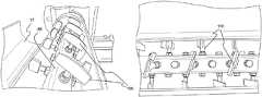
- FIGS. 6-8show portions of the fiber-slurry mixer 32 with a door 37 of its mixing chamber in an open position to show views of the paddles 100 mounted on the shaft 88 by being threaded into the shaft 88 .
- FIG. 7depicts four linear rows of paddles in the mixer in this particular embodiment of mixer configuration.
- FIG. 8provides a close-up view of the mixer showing the orientation of the paddles 100 with respect to the central shaft 88 . Placement of the paddles 100 on the central shaft 88 in the spiral form can also be observed.
- the size, location, and orientation of raw material inlets ports (inlet conduits) of the fiber-slurry mixerare configured to ease introduction of the raw material into the fiber-slurry mixer and to minimize potential for blocking of ports from the slurry mixture in the mixer.
- the cementitious slurry from the slurry mixeris preferably conveyed using a slurry hose to the fiber-slurry mixer and introduced into the fiber-slurry mixer through an inlet port setup to accept the slurry hose.
- the cementitious slurry from the slurry mixermay be gravity fed to the fiber-slurry mixer.
- the fiberscan be introduced into the fiber-slurry mixer gravimetrically or volumetrically using a variety of metering equipment such as screw feeders or vibratory feeders.
- Fiberscan be conveyed from a fiber feeder to the fiber-slurry mixer by a variety of conveying devices.
- fiberscan be transferred using screws (augers), air conveying, or simple gravity deposition.
- Discrete or chopped fiberscan be made of different reinforcing fiber materials including fiberglass; polymeric materials such as polypropylene, polyethylene, polyvinyl alcohol, etc.; carbon; graphite; aramid; ceramic; steel; cellulosic, paper, or natural fibers such as jute or sisal; or a combination thereof.
- the fiber lengthis about 2 inches or lower, more preferably less than 1.5 inches or lower and most preferably less than 0.75 inches or lower.
- FIGS. 9 and 10show the fiber-slurry mixture is in panel production.
- a cementitious panel production lineis diagrammatically shown and is generally designated 10 .
- the production line 10includes a support frame or forming table 12 having a plurality of legs 13 or other supports. Included on the support frame 12 is a moving carrier 14 , such as an endless rubber-like conveyor belt with a smooth, water-impervious surface, however porous surfaces are contemplated.
- the support frame 12may be made of at least one table-like segment, which may include designated legs 13 or other support structure.
- the support frame 12also includes a main drive roll 16 at a distal end 18 of the frame 12 , and an idler roll 20 at a proximal end 22 of the frame 12 .
- At least one belt tracking and/or tensioning device 24is typically provided for maintaining a desired tension and positioning of the carrier 14 upon the rolls 16 , 20 .
- the cementitious panelsare produced continuously as the moving carrier proceeds in a direction “T” from the proximal end 22 to the distal end 18 .
- a web 26 of release paper, polymer film, a plastic carrier, slip sheet, or forming mold, for supporting a slurry prior to settingmay be provided and laid upon the carrier 14 to protect it and/or keep it clean.
- individual sheets(not shown) of a relatively rigid material, e.g., sheets of polymer plastic, may be placed on the carrier 14 .
- These carrier films or sheetsmay be removed from the produced panels at the end of the line or they may be incorporated as a permanent feature in the panel as part of the overall composite design.
- these films or sheetsWhen these films or sheets are incorporated as a permanent feature in the panel they may provide enhanced attributes to the panel including improved aesthetics, enhanced tensile and flexural strengths, enhanced impact and blast resistance, enhanced environmental durability such as resistance to water and water vapor transmission, freeze-thaw resistance, salt-scaling resistance, and chemical resistance.
- Continuous reinforcement 44such as a roving or a web of reinforcing scrim such as fiberglass scrim may be provided for embedding in the fiber-slurry mixture prior to setting and reinforcing the resulting cementitious panels.
- the continuous rovings and/or reinforcing scrim roll 42are fed through the headbox 40 to be laid upon the mixture on the carrier 14 .
- the continuous scrim or rovingscan be made of different reinforcing fiber materials including fiberglass; polymeric materials such as polypropylene, polyethylene, polyvinyl alcohol, etc; carbon; graphite; aramid; ceramic; steel; cellulosic or natural fibers such as jute or sisal; or a combination thereof.
- a rovingis an assemblage of continuous reinforcing monofilaments. Scrim is a web of continuous fibers running in the machine direction and the cross-direction. Reinforcement may also be provided as a nonwoven fiber web made of discrete reinforcement fibers.
- the nonwoven fiber webmay be made of organic fibers such as polyolefin fibers or inorganic fibers such or fiberglass or a combination thereof. Fibrous webs made of metal fibers are also contemplated as part of the present invention.
- the carrier 14is moved along the support frame 12 by a combination of motors, pulleys, belts or chains which drive the main drive roll 16 as is known in the art. It is contemplated that the speed of the carrier 14 (forming belt) of the forming line may vary to suit the product being made.
- the fiber-slurry mixturetravels in direction “T”.
- the present production line 10includes a continuous slurry mixer 2 .
- the slurry mixermay be a single shaft or dual shaft mixer.
- Dry powder feeder 4(one or more may be employed) feeds dry components of the cementitious composition, except for reinforcing fibers, to the slurry mixer 2 .
- Liquid pump 6(one or more may be employed) feeds to the slurry mixer 2 aqueous medium, such as water, with liquid or water soluble additives.
- the slurry mixer 2mixes the dry components and the aqueous medium to form a cementitious slurry 31 .
- the cementitious slurry 31feeds a first slurry accumulator and positive displacement pump 30 which pumps the slurry to a fiber-slurry mixer 32 .
- a fiber feeder 34feeds fibers to the fiber-slurry mixer 32 .
- the fibers and slurryare mixed to form a fiber-slurry mixture 36 .
- Fiber-slurry mixture 36feeds a second slurry accumulator and positive displacement pump 38 which pumps the fiber-slurry mixture 36 to a headbox 40 .
- Headbox 40deposits the fiber-slurry mixture on the web 26 of release paper (if present) and/or, if present, continuous reinforcement provided by rovings and/or scrim, traveling on the moving carrier 14 .
- Continuous reinforcement in form of rovings or scrim or nonwoven fiber matmay be deposited on either one or both surfaces of the panel.
- continuous reinforcement 44 provided by fiber rovings or spools and/or scrim roll and/or nonwoven fiber mat 42is also passed through the headbox 40 as shown in FIG. 9 to deposit on top of the deposited fiber-slurry mixture 46 .
- Bottom continuous reinforcementif desired, is fed behind the headbox 40 and it rests directly on top of the conveying/forming belt.
- the bottom continuous reinforcementpasses under the headbox 40 and the fiber-slurry mixture in the headbox 40 is poured directly on its top as the continuous reinforcement moves forward.
- continuous reinforcementcan be provided by web 26 or a roll (not shown) upstream to the headbox 40 in addition to the roll providing web 26 to lay the continuous reinforcement above web 26 .
- a forming vibrating plate 50may be provided under or slightly downstream on the location where the headbox 40 deposits the fiber-slurry mixture 46 .
- the slurry 46sets as it travels along the moving carrier 14 .
- a cutter 54panel cutting device
- the boards (FRC panels) 55are then placed on an unloading and curing rack 57 (See FIG. 10 ) and allowed to cure.
- the panel 55is formed directly on the forming belt 14 or optional release paper/slip sheets/forming molds/nonwoven fiber webs 26 .
- FIG. 10further shows edge formation and leakage prevention devices 80 .
- edge belts, edge rails or other suitable edge formation and leakage prevention devicesas explained elsewhere in this specification, for example belt-bonded slit formers, used singly or in combination.
- the fiber-cement mixtures produced by the method and apparatus of this inventioncontain cement, water, and other cement additives.
- the cementitious compositionspreferably avoid thickeners or other high viscosity processing aids at high dosage rates as commonly used with conventional fiber cement extrusion processes.
- the present slurriesavoid high viscosity cellulose ethers addition at high dosage rates.
- high viscosity cellulose etherswhich the present slurries avoid are methyl cellulose, hydroxypropyl methyl cellulose, and hydroxyethyl methylcellulose.
- the fiber-cement mixtures produced by the method and apparatus of this inventionare aqueous slurries which may be from a variety of settable cementitious slurries.
- compositions based on hydraulic cementsASTM defines “hydraulic cement” as follows: a cement that sets and hardens by chemical interaction with water and is capable of doing so under water.
- suitable hydraulic cementsare Portland cement, calcium aluminate cements (CAC), calcium sulfoaluminate cements (CSA), geopolymers, magnesium oxychloride cements (sorel cements), and magnesium phosphate cements.
- a preferred geopolymeris based on chemical activation of Class C fly ash.
- calcium sulfate hemihydratesets and hardens by chemical interaction with water, it is not included within the broad definition of hydraulic cements in the context of this invention.
- calcium sulfate hemihydratemay be included in fiber-cement mixtures produced by the method and apparatus of this invention.
- aqueous slurriesmay be based on calcium sulfate cements such as gypsum cements or plaster of Paris.
- Gypsum cementsare primarily calcined gypsum (calcium sulfate hemihydrate). It is customary in the industry to term calcined gypsum cements as gypsum cements.
- the fiber-cement mixturescontain sufficient water to achieve the desired slump test value and viscosity in combination with the other ingredients of the fiber-cement mixtures. If desired the composition may have a weight ratio of water-to-reactive powder of 0.20/1 to 0.90/1, preferably 0.20/1 to 0.70/1.
- the fiber-cement mixturesmay contain pozzolanic material such as silica fume, a finely divided amorphous silica which is the product of silicon metal and ferro-silicon alloy manufacture. Characteristically, it has very high silica content and low alumina content.
- pozzolanic propertiesincluding pumice, perlite, diatomaceous earth, tuff, trass, metakaolin, microsilica, and ground granulated blast furnace slag. Fly ash also has pozzolanic properties.
- the fiber-cement mixturesmay contain Ceramic microspheres and/or Polymer microspheres.
- the fiber-cement slurries made by the present methodis to produce structural cement panels (SCP panels) having reinforcing fibers such as fiberglass, particularly alkali resistant glass fibers.
- the cementitious slurry 31is preferably comprised of varying amounts of Portland cement, gypsum, aggregate, water, accelerators, plasticizers, superplasticizers, foaming agents, fillers and/or other ingredients well known in the art, and described in the patents listed below which have been incorporated by reference.
- the relative amounts of these ingredients, including the elimination of some of the above or the addition of others,may vary to suit the intended use of the final product.
- Water reducing admixture additivesoptionally can be included in the fiber-cement mixture, such as, for example, superplasticizer, to improve the fluidity of a hydraulic slurry. Such additives disperse the molecules in solution so they move more easily relative to each other, thereby improving the flowability of the entire slurry. Sulfonated melamines and sulfonated naphthalenes, and polycarboxylate based superplasticizers can be used as superplasticizers. Water reducing admixture additive can be present in an amount from 0% to 5%, preferably 0.5 to 5%, by weight of the wet finish fiber-slurry mixture.
- U.S. Pat. No. 6,620,487 to Tonyan et al.discloses a reinforced, lightweight, dimensionally stable structural cement panel (SCP) which employs a core of a continuous phase resulting from the curing of an aqueous mixture of calcium sulfate alpha hemihydrate, hydraulic cement, an active pozzolan and lime.
- the continuous phaseis reinforced with alkali-resistant glass fibers and containing ceramic microspheres, or a blend of ceramic and polymer microspheres, or being formed from an aqueous mixture having a weight ratio of water-to-reactive powder of 0.6/1 to 0.7/1 or a combination thereof.
- At least one outer surface of the SCP panelsmay include a cured continuous phase reinforced with glass fibers and containing sufficient polymer spheres to improve nailability or made with a water-to-reactive powders ratio to provide an effect similar to polymer spheres, or a combination thereof.
- the compositionmay have a weight ratio of water-to-reactive powder of 0.20/1 to 0.90/1, preferably 0.20/1 to 0.70/1.
- a typical formulationwould comprise as the reactive powder, on a dry basis, 35 to 75 wt. % (typically 45-65 or 55 to 65 wt. %) calcium sulfate alpha hemihydrate, 20 to 55 wt. % (typically 25-40 wt. %) hydraulic cement such as Portland cement, 0.2 to 3.5 wt. % lime, and 5 to 25 wt. % (typically 10-15 wt.
- the continuous phase of the panelwould be uniformly reinforced with alkali-resistant glass fibers and would contain 20-50% by weight of uniformly distributed lightweight filler particles selected from the group consisting of ceramic microspheres, glass microspheres, plastic (polymer) microspheres, fly ash cenospheres, and perlite.
- An example of a formulation for the composite slurryincludes from 42 to 68 wt. % reactive powders, 23 to 43 wt. % ceramic microspheres, 0.2 to 1.0 wt. % polymer microspheres, and 5 to 15 wt. % alkali-resistant glass fibers, based on the total dry ingredients.
- U.S. Pat. No. 8,038,790 to Dubey et alprovides another example of a preferred formulation for the composite slurry which includes an aqueous mixture of a cementitious composition comprising, on a dry basis, 50 to 95 wt % reactive powder, 1 to 20 wt % of coated hydrophobic expanded perlite particles uniformly distributed as lightweight filler therein, the coated hydrophobic perlite particles having a diameter in the range of about 1 to 500 microns (micrometers), a median diameter of 20 to 150 microns (micrometers) and an effective particle density (specific gravity) of less than about 0.50 g/cc, 0 to 25 wt % hollow ceramic microspheres, and 3 to 16 wt.
- a cementitious compositioncomprising, on a dry basis, 50 to 95 wt % reactive powder, 1 to 20 wt % of coated hydrophobic expanded perlite particles uniformly distributed as lightweight filler therein, the coated hydrophobic perlite particles having a diameter in the
- the reactive powdercomprises: 25 to 75 wt. % calcium sulfate alpha hemihydrate, 10 to 75 wt. % hydraulic cement comprising Portland cement, 0 to 3.5 wt. % lime, and 5 to 30 wt. % of an active pozzolan; and the panel having a density of 50 to 100 pounds per cubic foot.
- compositions for the composite fiber-slurry mixtureare preferred, the relative amounts of these ingredients, including the elimination of some of the above or the addition of others, may vary to suit the intended use of the final product.
- a fiber-slurry feeder(also known as a forming assembly) receives a supply of fiber-slurry mixture 36 from the fiber-slurry mixer 32 .
- the slurry feed apparatusis a fiber-slurry headbox 40 .
- a headboxis a preferred type of forming assembly.
- Other types of forming assemblies suitable in the present inventioninclude: cylindrical screed rolls, roller coaters, vibrating plates with a gap at the bottom, vibrating plates (top and bottom) with a gap in the middle.
- FIGS. 9-15show forming assembly (slurry feed apparatus) in the form of a headbox 40 .
- Different types of forming assembliesmay also be combined and/or used in series to produce the product. For example, a headbox may be used in combination with a screed roll or a vibrating plate.
- One preferred forming assemblyfor depositing a slurry upon a moving forming web of a structural cementitious panel (SCP panel) production line or the like where settable slurries are used for producing fiber reinforced concrete (FRC) building panels or board having a direction of travel, comprises:
- the preferred headbox 40is disposed transversely to the direction of travel “T” of the carrier 14 .
- the fiber-slurry mixtureis deposited in a cavity of the headbox 40 and discharges through a discharge opening of the headbox onto the moving carrier web 14 (conveyor belt).
- the preferred headbox 40consists of a corrosion resistant material (for example, stainless steel) and has specific geometry to provide a reservoir for the slurry, height adjustment and support mounts to adjust slurry gap opening, and a curved transition to a straight lip to smoothly and evenly distribute the flow of slurry.
- the curved transitionalso provides a means to introduce a reinforcing fiberglass scrim (if needed) from above the headbox.
- An adjustable sealis provided at the back of the headbox in order to prevent any leakage. Reinforcing glass fiber scrim may also be added from underneath the headbox. Both scrim systems have adjustment for tracking purposes.
- the vibration unitis a single mass system consists of a table, springs, and two motors which direct forces directly into the mat and cancel out in other directions.
- This unitis placed under the headbox and it extends about 2 to 24 inches, or about 3 to 12 inches or about 3 to 6 inches beyond the headbox.
- the headbox height adjustment and support systemcan either be manually adjusted, mechanically operated, or electrically driven.
- the entire forming assemblyhas several advantages:
- the fiber reinforced cementitious slurrycan be pumped through a hose and hose oscillator system into the headbox 40 or it may be dropped into the headbox 40 directly from the fiber-slurry mixer 32 .
- the oscillator systemwould be used in either case to agitate the slurry.
- Thickness of the product formed using the headbox 40is controlled by the slurry flow rate in the headbox 40 , the amount of slurry elevation head in the headbox 40 , and headbox discharge opening gap for a given line speed.
- the discharge opening gap of the headbox 40is a transverse opening through which the fiber-slurry mixture discharges from the headbox 40 onto the moving carrier web 14 .
- the fiber-slurry mixture from the headboxdeposits onto the moving carrier 14 in one step at close to the desired thickness and finish of the final panel 55 .
- Vibrationmay be added to improve formation and different forms of continuous reinforcements such as scrims, nonwoven fiber mats and rovings may be added to improve flexural strength of the formed product.
- a vibration unit 50may be located below the headbox 40 under the conveyor belt 14 .
- the vibration unit 50is typically a single mass system of a table, springs, and two motors which direct forces directly into the deposited mat of fiber-cement slurry and cancel out in other directions. This unit 50 is placed under the headbox 40 and extends about 3 to 6 inches beyond the headbox.
- the headbox 40deposits an even layer of the fiber-slurry mixture of relatively controlled thickness upon the moving carrier web 14 .
- Suitable layer thicknessesrange from about 0.125 to 2 inches thick, preferably 0.25 to 1 inches thick, typically 0.40 to 0.75 inches thick.
- the fiber-slurry mixtureis completely deposited as a continuous curtain or sheet of slurry uniformly directed down to within a distance of about 1.0 to about 1.5 inches (2.54 to 3.81 cm.) of the carrier web 14 .
- the frame 12may have forming devices provided to shape an upper surface of the setting slurry-fiber mixture 46 traveling on the belt 14 .
- the production line 10may include smoothing devices, also termed vibrating screed plates 52 , to gently smooth the upper surface of the panel (see FIGS. 9 and 10 ).
- the smoothing device 52facilitates the distribution of the fibers throughout the deposited slurry 46 that will become the FRC panel 55 , and provides a more uniform upper surface.
- the smoothing device 52may either be pivoted or rigidly mounted to the forming line frame assembly.
- the layer of slurryhas begun to set, and the respective panels 55 are separated from each other by a cutting device 54 , which in a typical embodiment is a water jet cutter.
- the cutting device 54is disposed relative to the line 10 and the frame 12 so panels are produced having a desired length.
- the cutting device 54may be mounted to cut perpendicularly to the direction of travel of the web 14 .
- such cutting devicesare known to be mounted to the production line 10 on an angle to the direction of web travel.
- the separated FRC panels 55are stacked for further handling, packaging, storage and/or shipment as is well known in the art.
- the resulting FRC panel 55is constructed so the fibers 30 are uniformly distributed throughout the panel. This has been found to enable the production of relatively stronger panels with relatively less, more efficient use of fibers.
- the volume fraction of fibers relative to the volume of slurry in each layerpreferably constitutes approximately in the range of 1% to 5% by volume, preferably 1.5% to 3% by volume, of the fiber-slurry mixture 46 .
- FIG. 10shows the method of FIG. 9 as a composite view of a process flow chart for the portion of the cementitious panel production line suitable for use with the present fiber-slurry mixing device upstream of the headbox and a top view of the production line downstream of the headbox.
- FIG. 11shows a production line 10 A which is a first variation of the cementitious panel production line of FIG. 9 as a composite view of a process flow chart for the portion of the cementitious panel production line suitable for use with the present fiber-slurry mixing device upstream of the headbox and a top view of the cementitious panel production line downstream of the headbox 40 .
- Thisomits slurry accumulator and positive displacement pump 30 .
- FIG. 12shows a production line 10 B which is a second variation of the cementitious panel production line of FIG. 9 as a composite view of a process flow chart for the portion of the cementitious panel production line suitable for use with the present fiber-slurry mixing device upstream of the headbox and a top view of the cementitious panel production line downstream of the headbox 40 .
- Thisomits slurry accumulator and positive displacement pump 38 .
- FIG. 13shows a production line 10 C which is a third variation of the cementitious panel production line of FIG. 9 as a composite view of a process flow chart for the portion of the cementitious panel production line suitable for use with the present fiber-slurry mixing device upstream of the headbox and a top view of the cementitious panel production line downstream of the headbox 40 .
- Thisomits slurry accumulator and positive displacement pump 30 and slurry accumulator and positive displacement pump 38 .
- fiber-slurry mixer 32 and fiber-slurry mixture 36 in these production line variations, and other like numbered elements shownare the same as used in the production line 10 of FIG. 9 and FIG. 10 .
- FIGS. 9 through 13show process flow diagrams for a manufacturing process that utilizes the fiber-slurry mixer of this invention for producing FRC panels.
- FIGS. 9 through 13show process flow diagrams for a manufacturing process that utilizes the fiber-slurry mixer of this invention for producing FRC panels.
- other uses and applications of the fiber-slurry mixer of this inventionare possible and contemplated as part of this disclosure.
- FIG. 14shows a photograph of a slump patty 101 of a fiber reinforced cementitious slurry mixture made using the fiber-slurry mixer of the present invention.
- FIG. 15is a thickness profile of a 3 ⁇ 4′′ thick panel FRC panel produced using fiber-slurry mixture produced by the method this invention. It shows consistent thickness achieved when a single layer was deposited.
- the fiber-slurry mixturecontained Portland cement, gypsum, and glass fibers.
Landscapes
- Chemical & Material Sciences (AREA)
- Engineering & Computer Science (AREA)
- Chemical Kinetics & Catalysis (AREA)
- Mechanical Engineering (AREA)
- Structural Engineering (AREA)
- Ceramic Engineering (AREA)
- Dispersion Chemistry (AREA)
- Automation & Control Theory (AREA)
- Manufacturing & Machinery (AREA)
- Preparation Of Clay, And Manufacture Of Mixtures Containing Clay Or Cement (AREA)
- Accessories For Mixers (AREA)
- Mixers Of The Rotary Stirring Type (AREA)
Abstract
Description
- an elongated mixing chamber defined by a horizontal (typically cylindrical) housing having an interior side wall,
- at least one fiber inlet port to introduce reinforcement fibers into the mixing chamber in a first feed section of the horizontal housing, and
- at least one cementitious slurry inlet port to introduce cementitious slurry mixture into the chamber in a second feed section of the horizontal housing,
- a fiber-slurry mixture outlet port at a second discharge end section of the horizontal housing to discharge the fiber reinforced cementitious slurry mixture produced by the mixer, and
- a venting port to remove any air introduced into the mixing chamber from raw material feed,
- a rotating horizontally oriented shaft mounted within the elongated mixing chamber traversing from one end of the fiber-slurry mixer to another end of the fiber-slurry mixer,
- an elongated mixing chamber defined by a horizontal (typically cylindrical) housing having an interior side wall,
- at least one fiber inlet port to introduce reinforcement fibers into the mixing chamber in a first feed section of the horizontal housing, and
- at least one cementitious slurry inlet port to introduce cementitious slurry mixture into the chamber in a second feed section of the horizontal housing,
- a fiber-slurry mixture outlet port at a second discharge end section of the horizontal cylindrical housing to discharge the fiber reinforced cementitious slurry mixture produced by the mixer, and
- a venting port to remove any air introduced into the mixing chamber from raw material feed,
- a horizontally oriented shaft mounted for rotating in the elongated mixing chamber, the horizontally oriented shaft traversing from one end of the mixer to another,
- a headbox mounted transverse to the direction of travel of the moving web, having a transverse back wall, sidewalls, a concave transverse front wall, an open top, and an open bottom for directing slurry onto the forming web;
- a moveable dam releasably attached to the back wall, a seal attached to a bottom wall of the dam; and
- headbox height adjustment and support system extending from opposed said sidewalls.
Claims (16)
Priority Applications (15)
| Application Number | Priority Date | Filing Date | Title |
|---|---|---|---|
| US15/662,932US11173629B2 (en) | 2016-08-05 | 2017-07-28 | Continuous mixer and method of mixing reinforcing fibers with cementitious materials |
| CN201780045053.7ACN109476042B (en) | 2016-08-05 | 2017-08-04 | Continuous mixer and method for mixing reinforcing fibers with cementitious materials |
| BR112019000928-0ABR112019000928B1 (en) | 2016-08-05 | 2017-08-04 | CONTINUOUS MIXER AND METHOD OF MIXING REINFORCING FIBERS WITH CEMENTICIOUS MATERIALS |
| JP2019502190AJP7018051B2 (en) | 2016-08-05 | 2017-08-04 | Continuous mixer, and how to mix reinforced fiber and cement material |
| PL17751581TPL3493961T3 (en) | 2016-08-05 | 2017-08-04 | Continuous mixer and method of mixing reinforcing fibers with cementitious materials |
| CA3032829ACA3032829A1 (en) | 2016-08-05 | 2017-08-04 | Continuous mixer and method of mixing reinforcing fibers with cementitious materials |
| PCT/US2017/045420WO2018027090A1 (en) | 2016-08-05 | 2017-08-04 | Continuous mixer and method of mixing reinforcing fibers with cementitious materials |
| AU2017306682AAU2017306682B2 (en) | 2016-08-05 | 2017-08-04 | Continuous mixer and method of mixing reinforcing fibers with cementitious materials |
| MX2019000875AMX2019000875A (en) | 2016-08-05 | 2017-08-04 | Continuous mixer and method of mixing reinforcing fibers with cementitious materials. |
| EP17751581.4AEP3493961B1 (en) | 2016-08-05 | 2017-08-04 | Continuous mixer and method of mixing reinforcing fibers with cementitious materials |
| PE2019000264APE20190309A1 (en) | 2016-08-05 | 2017-08-04 | CONTINUOUS MIXER AND METHOD FOR MIXING REINFORCEMENT FIBERS WITH CEMENTOUS MATERIALS |
| KR1020197004800AKR102434310B1 (en) | 2016-08-05 | 2017-08-04 | Continuous mixer and method for mixing reinforcing fibers and cementitious materials |
| CL2019000216ACL2019000216A1 (en) | 2016-08-05 | 2019-01-28 | Continuous mixer and method for mixing reinforcement fibers with cementitious materials. |
| SA519400994ASA519400994B1 (en) | 2016-08-05 | 2019-01-29 | Continuous Mixer and Method of Mixing Reinforcing Fibers with Cementitious Materials |
| CONC2019/0001752ACO2019001752A2 (en) | 2016-08-05 | 2019-02-26 | Continuous mixer and method for mixing reinforcement fibers with cementitious materials |
Applications Claiming Priority (2)
| Application Number | Priority Date | Filing Date | Title |
|---|---|---|---|
| US201662371578P | 2016-08-05 | 2016-08-05 | |
| US15/662,932US11173629B2 (en) | 2016-08-05 | 2017-07-28 | Continuous mixer and method of mixing reinforcing fibers with cementitious materials |
Publications (2)
| Publication Number | Publication Date |
|---|---|
| US20180036911A1 US20180036911A1 (en) | 2018-02-08 |
| US11173629B2true US11173629B2 (en) | 2021-11-16 |
Family
ID=61071353
Family Applications (1)
| Application Number | Title | Priority Date | Filing Date |
|---|---|---|---|
| US15/662,932Active2040-07-02US11173629B2 (en) | 2016-08-05 | 2017-07-28 | Continuous mixer and method of mixing reinforcing fibers with cementitious materials |
Country Status (15)
| Country | Link |
|---|---|
| US (1) | US11173629B2 (en) |
| EP (1) | EP3493961B1 (en) |
| JP (1) | JP7018051B2 (en) |
| KR (1) | KR102434310B1 (en) |
| CN (1) | CN109476042B (en) |
| AU (1) | AU2017306682B2 (en) |
| BR (1) | BR112019000928B1 (en) |
| CA (1) | CA3032829A1 (en) |
| CL (1) | CL2019000216A1 (en) |
| CO (1) | CO2019001752A2 (en) |
| MX (1) | MX2019000875A (en) |
| PE (1) | PE20190309A1 (en) |
| PL (1) | PL3493961T3 (en) |
| SA (1) | SA519400994B1 (en) |
| WO (1) | WO2018027090A1 (en) |
Families Citing this family (25)
| Publication number | Priority date | Publication date | Assignee | Title |
|---|---|---|---|---|
| US10272399B2 (en) | 2016-08-05 | 2019-04-30 | United States Gypsum Company | Method for producing fiber reinforced cementitious slurry using a multi-stage continuous mixer |
| US11173629B2 (en)* | 2016-08-05 | 2021-11-16 | United States Gypsum Company | Continuous mixer and method of mixing reinforcing fibers with cementitious materials |
| US10981294B2 (en) | 2016-08-05 | 2021-04-20 | United States Gypsum Company | Headbox and forming station for fiber-reinforced cementitious panel production |
| US11224990B2 (en)* | 2016-08-05 | 2022-01-18 | United States Gypsum Company | Continuous methods of making fiber reinforced concrete panels |
| CN109012459A (en)* | 2018-10-10 | 2018-12-18 | 重庆腾治科技有限公司 | Agravic mixing arrangement for grouting material production |
| US11518141B2 (en) | 2018-11-01 | 2022-12-06 | United States Gypsum Company | Water barrier exterior sheathing panel |
| US20200261864A1 (en)* | 2019-02-15 | 2020-08-20 | United States Gypsum Company | System and method for continuous manufacture of joint compound |
| CN109847641B (en)* | 2019-03-19 | 2021-10-15 | 广东顺德景合盟科技有限公司 | Scraping equipment of horizontal type art paint stirring machine |
| CN109855942B (en)* | 2019-03-20 | 2021-09-21 | 南京六合高新建设发展有限公司 | Structural ceramic product detection equipment |
| CN109822741B (en)* | 2019-03-20 | 2023-09-19 | 岭南师范学院 | A mixer for processing ceramic water cups that facilitates thorough mixing |
| CN113767000A (en)* | 2019-04-15 | 2021-12-07 | 吉野石膏株式会社 | Mixer for pretreatment, apparatus for producing gypsum slurry, apparatus for producing building surface material, method for producing pretreated calcined gypsum, method for producing gypsum slurry, and method for producing building surface material |
| US10759697B1 (en) | 2019-06-11 | 2020-09-01 | MSB Global, Inc. | Curable formulations for structural and non-structural applications |
| US11674317B2 (en) | 2019-12-23 | 2023-06-13 | United States Gypsum Company | Apparatus and process with a vibratory angled plate and/or fixed horizontal plate for forming fiber-reinforced cementitious panels with controlled thickness |
| CN111619000A (en)* | 2020-05-13 | 2020-09-04 | 福建航融建材科技有限公司 | Double-horizontal-shaft mixer for concrete trial-production |
| CN112191437B (en)* | 2020-09-22 | 2022-11-01 | 东佳精密光电(南京)有限公司 | Roller coating equipment convenient to clean cam in liquid storage tank |
| CN112619501A (en)* | 2020-11-28 | 2021-04-09 | 德清科邦晶体纤维有限公司 | Cotton pulp preparation mixing arrangement of polycrystal mullite fibreboard |
| CN114684837B (en)* | 2020-12-30 | 2023-12-22 | 内蒙古亿利化学工业有限公司 | Recycling device and method for preparing active calcium oxide from calcium carbide slag as calcium carbide raw material |
| CN114074376B (en)* | 2021-11-30 | 2023-03-24 | 中铁八局集团第一工程有限公司 | High-ductility concrete stirring device and construction method thereof |
| CN115286293B (en)* | 2022-08-01 | 2023-10-13 | 汨罗景通新材料有限公司 | Asphalt concrete preparation method |
| CN115338951B (en)* | 2022-08-08 | 2023-06-09 | 南通理工学院 | Spraying and mixing device and method for preparing mixed fiber concrete by adopting same |
| US11940363B1 (en)* | 2023-03-28 | 2024-03-26 | Kuwait University | System for monitoring and enhancing the physical stability of dispersed particles in flowing suspensions |
| WO2025109481A1 (en)* | 2023-11-21 | 2025-05-30 | Comas - Costruzioni Macchine Speciali - S.P.A. | Mixer and method for making a plant-based mixture in a continuous process |
| CN117735905B (en)* | 2023-12-22 | 2024-06-04 | 济宁广进新型材料有限公司 | High-strength spraying material for underground coal mine building and preparation device thereof |
| CN117901371B (en)* | 2024-01-22 | 2024-10-22 | 湖南齐丰新材料有限公司 | A kind of magnesia taphole mud production equipment and preparation method for submerged arc furnace |
| CN118493630B (en)* | 2024-06-19 | 2025-03-04 | 重庆大学 | A coconut shell fiber reinforced coral aggregate concrete mixing equipment |
Citations (99)
| Publication number | Priority date | Publication date | Assignee | Title |
|---|---|---|---|---|
| DE1007684B (en) | 1955-01-24 | 1957-05-02 | Lauterberger Blechwarenfabrik | Continuously working mixer for preparing mortar or the like. |
| US3284980A (en) | 1964-07-15 | 1966-11-15 | Paul E Dinkel | Hydraulic cement panel with low density core and fiber reinforced high density surface layers |
| GB1085592A (en) | 1964-11-23 | 1967-10-04 | St Annes Board Mill Co Ltd | Dewatering watery pulp to form paper, board or tissue |
| US3354031A (en) | 1964-07-16 | 1967-11-21 | Carey Philip Mfg Co | Cement-asbestos products and improvement in the manufacture thereof |
| DE2312436A1 (en) | 1972-03-13 | 1973-10-11 | Kobe Steel Ltd | Rotating screw mixer - for compounding dmc and similar materials |
| US3785621A (en) | 1969-09-29 | 1974-01-15 | Nat Res Dev | Preparation of mixes |
| US3885774A (en) | 1972-07-22 | 1975-05-27 | Caledonian Mining Co Ltd | Apparatus for preparing and dispensing mixtures of concrete and fibres |
| US3972972A (en) | 1973-04-21 | 1976-08-03 | Onoda Cement Company, Ltd. | Process for producing a board of cement-like material reinforced by fibrous material and apparatus for the process |
| US4093471A (en) | 1975-07-04 | 1978-06-06 | Pilkington Brothers Limited | Glass fiber reinforced cement composite materials |
| US4187275A (en) | 1974-06-14 | 1980-02-05 | H. H. Robertson Company | Method and apparatus for producing shaped glass fiber reinforced cementitious articles |
| US4205919A (en) | 1975-08-20 | 1980-06-03 | London Brick Buildings Limited | Mixer for and method for mixing particulate constituents |
| GB2048446A (en) | 1979-03-13 | 1980-12-10 | Ito Y | Drying fine granular material, particularly in the preparation of mortar or concrete |
| US4298413A (en) | 1980-03-03 | 1981-11-03 | Teare John W | Method and apparatus for producing concrete panels |
| JPS5743805A (en) | 1980-08-29 | 1982-03-12 | Matsushita Electric Works Ltd | Method of molding inorganic molding material |
| EP0003705B1 (en) | 1978-02-08 | 1982-09-08 | Saint-Gobain Industries | Method and device for manufacturing a plaster web or plaster panels and panels so produced |
| US4450022A (en) | 1982-06-01 | 1984-05-22 | United States Gypsum Company | Method and apparatus for making reinforced cement board |
| US4504533A (en) | 1980-03-29 | 1985-03-12 | Gebr. Knauf Westdeutsche Gipswerke | Gypsum construction sheet with glass fiber/non-woven felt lining sheet |
| GB2166660A (en) | 1984-11-07 | 1986-05-14 | Green Bay Packaging Inc | Filtering and washing cellulosic pulp |
| US4793892A (en) | 1987-09-24 | 1988-12-27 | Glascrete, Inc. | Apparatus for producing reinforced cementitious panel webs |
| US5018673A (en)* | 1988-11-24 | 1991-05-28 | Draiswerke Gmbh | Continuously working mixer |
| US5051221A (en)* | 1989-02-26 | 1991-09-24 | Wurtex Maschinenbau Hofmann Gmbh & Co | Method for the manufacture of a moist mixture from plaster of Paris and fibres |
| JPH04189104A (en) | 1990-11-22 | 1992-07-07 | Kyowa Giken Kk | Continuous kneading method of slurry mixed with fiber material |
| US5221386A (en) | 1986-02-20 | 1993-06-22 | United States Gypsum Company | Cement board having reinforced edges |
| US5306452A (en) | 1993-03-23 | 1994-04-26 | Apv Chemical Machinery Inc. | Devolatilizing and/or processing systems and methods |
| US5366676A (en) | 1991-12-17 | 1994-11-22 | Shigeru Kobayashi | Method and apparatus for manufacturing concrete panels by continuous pressing |
| JPH08118330A (en) | 1994-10-21 | 1996-05-14 | Matsushita Electric Works Ltd | Production of inorganic panel |
| CN1205264A (en) | 1997-07-14 | 1999-01-20 | 葛焕林 | Prodn. tech. and its appts. for glass fibre reinforced cement slab products |
| US5891374A (en) | 1994-02-01 | 1999-04-06 | Northwestern University | Method of making extruded fiber reinforced cement matrix composites |
| US5902528A (en) | 1997-06-13 | 1999-05-11 | Spragg; Peter H. | Method of making an article from a lightweight cementitious composition |
| CN2344149Y (en) | 1998-10-16 | 1999-10-20 | 汪孝文 | Fibre and slurry mixed spraying machine |
| US6248214B1 (en) | 1998-10-05 | 2001-06-19 | Voith Sulzer Papiertechnik Patent Gmbh | Headbox |
| US6248156B1 (en) | 1999-05-03 | 2001-06-19 | Scott Equipment Company | Particulate capture system and method of use |
| US6299970B1 (en) | 1989-10-12 | 2001-10-09 | Georgia-Pacific Gypsum Corporation | Fire-resistant gypsum fiberboard |
| DE10060328C1 (en) | 2000-12-04 | 2001-12-20 | Pama Papiermaschinen Gmbh | High turbulence headbox nozzle for a high speed papermaking machine, has reinforcing ribs connected to nozzle walls, resisting widening of the nozzle slot |
| JP2003127129A (en) | 2001-10-26 | 2003-05-08 | Daiho Constr Co Ltd | Method for producing wet refractory material, apparatus for producing wet refractory material, and apparatus for spraying wet refractory material |
| JP2003516880A (en) | 1999-12-15 | 2003-05-20 | ジェームズ ハーディー リサーチ プロプライアトリー リミテッド | Method and apparatus for extruding cementitious articles |
| US6620487B1 (en) | 2000-11-21 | 2003-09-16 | United States Gypsum Company | Structural sheathing panels |
| US20040219845A1 (en) | 2003-04-29 | 2004-11-04 | Graham Samuel E. | Fabric reinforced cement |
| US20050064164A1 (en) | 2003-09-18 | 2005-03-24 | United States Gypsum Company | Multi-layer process and apparatus for producing high strength fiber-reinforced structural cementitious panels |
| US6986812B2 (en) | 2003-09-18 | 2006-01-17 | United States Gypsum Company | Slurry feed apparatus for fiber-reinforced structural cementitious panel production |
| EP1653000A1 (en) | 2004-08-06 | 2006-05-03 | Voith Paper Patent GmbH | Headbox for machine for producing a fibrous web, in particular a paper or board web |
| US7049251B2 (en) | 2003-01-21 | 2006-05-23 | Saint-Gobain Technical Fabrics Canada Ltd | Facing material with controlled porosity for construction boards |
| US20060144005A1 (en) | 2004-12-30 | 2006-07-06 | United States Gypsum Company | Non-combustible reinforced cementitious lightweight panels and metal frame system for flooring |
| US20060168906A1 (en) | 2005-01-27 | 2006-08-03 | United States Gypsum Company | Non-combustible reinforced cementitious lighweight panels and metal frame system for a fire wall and other fire resistive assemblies |
| US20060168905A1 (en) | 2002-11-05 | 2006-08-03 | Wilfried Blanc | Light-converting material comprising a barium magenesium silicate as additive |
| US20060174572A1 (en) | 2005-01-27 | 2006-08-10 | United States Gypsum Company | Non-combustible reinforced cementitious lightweight panels and metal frame system for shear walls |
| US20060185267A1 (en) | 2005-01-27 | 2006-08-24 | United States Gypsum Company | Non-combustible reinforced cementitious lightweight panels and metal frame system for roofing |
| US20060233043A1 (en)* | 2005-04-14 | 2006-10-19 | Ekato Ruhr- Und Mischtechnik Gmbh | Treatment plant |
| US20070110970A1 (en) | 2003-09-18 | 2007-05-17 | Ashish Dubey | Multi-layer process and apparatus for producing high strength fiber-reinforced structural cementitious panels with enhanced fiber content |
| US20070148430A1 (en) | 2005-12-22 | 2007-06-28 | Gaurav Agrawal | Perforated, coated nonwoven mat |
| US20070149083A1 (en) | 2005-12-22 | 2007-06-28 | Gaurav Agrawal | Board formed from a cementitious material and a facer containing a laminate |
| US7347896B2 (en) | 2000-01-27 | 2008-03-25 | Tececo Pty Ltd | Reactive magnesium oxide cements |
| US7347895B2 (en) | 2004-09-16 | 2008-03-25 | United States Gypsum Company | Flexible hydraulic compositions |
| US7354876B2 (en) | 2003-07-09 | 2008-04-08 | Saint-Gobain Technical Fabrics Canada Ltd. | Fabric reinforcement and cementitious boards faced with same |
| US20080099133A1 (en) | 2006-11-01 | 2008-05-01 | United States Gypsum Company | Panel smoothing process and apparatus for forming a smooth continuous surface on fiber-reinforced structural cement panels |
| US7384514B2 (en) | 1997-01-24 | 2008-06-10 | Bpb Plc | Non-woven inorganic fiber mat |
| US7416636B2 (en) | 2001-11-09 | 2008-08-26 | Ahlstrom Glassfibre Oy | Method and apparatus for foam forming |
| JP2008207140A (en) | 2007-02-28 | 2008-09-11 | Fujita Corp | Continuous stirring device and continuous stirring method using the same |
| US20080308968A1 (en) | 2007-06-13 | 2008-12-18 | Immordino Jr Salvatore C | Method of making a low-dust building panel |
| US7513963B2 (en) | 2006-11-01 | 2009-04-07 | United States Gypsum Company | Method for wet mixing cementitious slurry for fiber-reinforced structural cement panels |
| US7524386B2 (en) | 2006-11-01 | 2009-04-28 | United States Gypsum Company | Method for wet mixing cementitious slurry for fiber-reinforced structural cement panels |
| WO2009085981A2 (en) | 2007-12-28 | 2009-07-09 | United States Gypsum Company | Cementitious boards with reinforced edges that resist impact damage |
| US20090239977A1 (en) | 2008-03-03 | 2009-09-24 | United States Government As Represented By The Secretary Of The Army | Self-leveling cementitious composition with controlled rate of strength development and ultra-high compressive strength upon hardening and articles made from same |
| WO2009142791A2 (en) | 2008-03-03 | 2009-11-26 | United States Gypsum Company | Process of manufacturing cement based armor panels |
| WO2009152615A1 (en) | 2008-06-20 | 2009-12-23 | Vidabode Group Inc. | A production system and method for manufacturing lightweight fiber reinforced concrete panels |
| JP4454715B2 (en) | 1999-03-23 | 2010-04-21 | 株式会社エーアンドエーマテリアル | Manufacturing method of fiber cement board using low heat cement |
| DE102008058222A1 (en) | 2008-11-19 | 2010-05-20 | Qualifire Materials Co. Ltd., Yixing | Continuously producing fire-resistant door panels in the form of plates in a sandwich-like composite made of non-woven material and foamed hardenable pasty magnesium oxychloride mixture, comprises placing non-woven material on base plates |
| US7732032B2 (en) | 2004-12-30 | 2010-06-08 | United States Gypsum Company | Lightweight, fiber-reinforced cementitious panels |
| US20100143682A1 (en) | 2008-10-30 | 2010-06-10 | United States Gypsum Company | Mat-Faced Cementitious Article and Method for Preparing Same |
| US20100151757A1 (en) | 2008-12-16 | 2010-06-17 | Saint-Gobain Technical Fabrics America, Inc. | Polyolefin coated fabric reinforcement and cementitious boards reinforced with same |
| US7754052B2 (en) | 2006-11-01 | 2010-07-13 | United States Gypsum Company | Process and apparatus for feeding cementitious slurry for fiber-reinforced structural cement panels |
| US7794221B2 (en) | 2007-03-28 | 2010-09-14 | United States Gypsum Company | Embedment device for fiber reinforced structural cementitious panel production |
| US7842629B2 (en) | 2003-06-27 | 2010-11-30 | Johns Manville | Non-woven glass fiber mat faced gypsum board and process of manufacture |
| US7846536B2 (en) | 2004-12-16 | 2010-12-07 | United States Gypsum Company | Building panels with aesthetic edges |
| US7845130B2 (en) | 2005-12-29 | 2010-12-07 | United States Gypsum Company | Reinforced cementitious shear panels |
| US7870698B2 (en) | 2006-06-27 | 2011-01-18 | United States Gypsum Company | Non-combustible reinforced cementitious lightweight panels and metal frame system for building foundations |
| US7897079B2 (en) | 2006-09-21 | 2011-03-01 | United States Gypsum Company | Method and apparatus for scrim embedment into wet processed panels |
| US7989370B2 (en) | 2003-10-17 | 2011-08-02 | Georgia-Pacific Gypsum Llc | Interior wallboard and method of making same |
| US20110186664A1 (en) | 2010-01-29 | 2011-08-04 | Scott Equipment Company | Dryer/Grinder |
| US8038790B1 (en)* | 2010-12-23 | 2011-10-18 | United States Gypsum Company | High performance non-combustible gypsum-cement compositions with enhanced water durability and thermal stability for reinforced cementitious lightweight structural cement panels |
| US8057915B2 (en) | 2007-05-31 | 2011-11-15 | United States Gypsum Company | Acoustical gypsum board panel and method of making it |
| US8061257B2 (en) | 2008-03-03 | 2011-11-22 | United States Gypsum Company | Cement based armor panel system |
| US8062741B2 (en) | 2008-03-03 | 2011-11-22 | U.S. Gypsum Company | Cement based laminated armor panels |
| US8128767B2 (en) | 2003-06-27 | 2012-03-06 | Johns Manville | Process for manufacturing gypsum board faced with non-woven glass fiber mat |
| US8163352B2 (en) | 2007-06-29 | 2012-04-24 | United States Gypsum Company | Method for smoothing cementitious slurry in the production of structural cementitious panels |
| US20120219747A1 (en) | 2009-11-13 | 2012-08-30 | Shigeki Kanao | Panel with decorative slate |
| US20120231233A1 (en) | 2011-03-07 | 2012-09-13 | Shigeki Kanao | Decorative lightweight panel |
| US20130075051A1 (en) | 2009-09-30 | 2013-03-28 | Marco Thomisch | Headbox for a machine for producing a fibrous material web, in particular a paper or cardboard web |
| US8461067B2 (en) | 2004-03-12 | 2013-06-11 | Georgia-Pacific Gypsum Llc | Use of pre-coated mat for preparing gypsum board |
| US20130186989A1 (en) | 2012-01-20 | 2013-07-25 | Scott Equipment Company | Paddle assembly |
| US8568544B2 (en) | 2007-02-12 | 2013-10-29 | United States Gypsum Company | Water resistant cementitious article and method for preparing same |
| US20130337251A1 (en) | 2011-02-11 | 2013-12-19 | Johns Manville | Glass Fibre Mat and Products Containing Glass Fibre Mats |
| US8770139B2 (en) | 2009-03-03 | 2014-07-08 | United States Gypsum Company | Apparatus for feeding cementitious slurry onto a moving web |
| US20140272404A1 (en) | 2013-03-15 | 2014-09-18 | Tremco Incorporated | Exterior sheathing panel with integrated air/water barrier membrane |
| CN204093355U (en) | 2014-08-14 | 2015-01-14 | 广西凯力福科技有限公司 | A kind of high viscosity ribbon dispersing stirrer and the ribbon dispersator with this ribbon dispersing stirrer |
| US20180036693A1 (en)* | 2016-08-05 | 2018-02-08 | United States Gypsum Company | Method for producing fiber reinforced cementitious slurry using a multi-stage continuous mixer |
| US20180036909A1 (en) | 2016-08-05 | 2018-02-08 | United States Gypsum Company | Headbox and forming station for fiber-reinforced cementitious panel production |
| WO2018027090A1 (en)* | 2016-08-05 | 2018-02-08 | United States Gypsum Company | Continuous mixer and method of mixing reinforcing fibers with cementitious materials |
| US20180036912A1 (en)* | 2016-08-05 | 2018-02-08 | United States Gypsum Company | Continuous methods of making fiber reinforced concrete panels |
- 2017
- 2017-07-28USUS15/662,932patent/US11173629B2/enactiveActive
- 2017-08-04EPEP17751581.4Apatent/EP3493961B1/enactiveActive
- 2017-08-04PEPE2019000264Apatent/PE20190309A1/enunknown
- 2017-08-04AUAU2017306682Apatent/AU2017306682B2/enactiveActive
- 2017-08-04PLPL17751581Tpatent/PL3493961T3/enunknown
- 2017-08-04JPJP2019502190Apatent/JP7018051B2/enactiveActive
- 2017-08-04CNCN201780045053.7Apatent/CN109476042B/enactiveActive
- 2017-08-04MXMX2019000875Apatent/MX2019000875A/enunknown
- 2017-08-04BRBR112019000928-0Apatent/BR112019000928B1/enactiveIP Right Grant
- 2017-08-04WOPCT/US2017/045420patent/WO2018027090A1/ennot_activeCeased
- 2017-08-04KRKR1020197004800Apatent/KR102434310B1/enactiveActive
- 2017-08-04CACA3032829Apatent/CA3032829A1/enactivePending
- 2019
- 2019-01-28CLCL2019000216Apatent/CL2019000216A1/enunknown
- 2019-01-29SASA519400994Apatent/SA519400994B1/enunknown
- 2019-02-26COCONC2019/0001752Apatent/CO2019001752A2/enunknown
Patent Citations (121)
| Publication number | Priority date | Publication date | Assignee | Title |
|---|---|---|---|---|
| DE1007684B (en) | 1955-01-24 | 1957-05-02 | Lauterberger Blechwarenfabrik | Continuously working mixer for preparing mortar or the like. |
| US3284980A (en) | 1964-07-15 | 1966-11-15 | Paul E Dinkel | Hydraulic cement panel with low density core and fiber reinforced high density surface layers |
| US3354031A (en) | 1964-07-16 | 1967-11-21 | Carey Philip Mfg Co | Cement-asbestos products and improvement in the manufacture thereof |
| GB1085592A (en) | 1964-11-23 | 1967-10-04 | St Annes Board Mill Co Ltd | Dewatering watery pulp to form paper, board or tissue |
| US3785621A (en) | 1969-09-29 | 1974-01-15 | Nat Res Dev | Preparation of mixes |
| DE2312436A1 (en) | 1972-03-13 | 1973-10-11 | Kobe Steel Ltd | Rotating screw mixer - for compounding dmc and similar materials |
| US3885774A (en) | 1972-07-22 | 1975-05-27 | Caledonian Mining Co Ltd | Apparatus for preparing and dispensing mixtures of concrete and fibres |
| US3972972A (en) | 1973-04-21 | 1976-08-03 | Onoda Cement Company, Ltd. | Process for producing a board of cement-like material reinforced by fibrous material and apparatus for the process |
| US4187275A (en) | 1974-06-14 | 1980-02-05 | H. H. Robertson Company | Method and apparatus for producing shaped glass fiber reinforced cementitious articles |
| US4093471A (en) | 1975-07-04 | 1978-06-06 | Pilkington Brothers Limited | Glass fiber reinforced cement composite materials |
| US4205919A (en) | 1975-08-20 | 1980-06-03 | London Brick Buildings Limited | Mixer for and method for mixing particulate constituents |
| EP0003705B1 (en) | 1978-02-08 | 1982-09-08 | Saint-Gobain Industries | Method and device for manufacturing a plaster web or plaster panels and panels so produced |
| GB2048446A (en) | 1979-03-13 | 1980-12-10 | Ito Y | Drying fine granular material, particularly in the preparation of mortar or concrete |
| US4298413A (en) | 1980-03-03 | 1981-11-03 | Teare John W | Method and apparatus for producing concrete panels |
| US4504533A (en) | 1980-03-29 | 1985-03-12 | Gebr. Knauf Westdeutsche Gipswerke | Gypsum construction sheet with glass fiber/non-woven felt lining sheet |
| JPS5743805A (en) | 1980-08-29 | 1982-03-12 | Matsushita Electric Works Ltd | Method of molding inorganic molding material |
| US4450022A (en) | 1982-06-01 | 1984-05-22 | United States Gypsum Company | Method and apparatus for making reinforced cement board |
| GB2166660A (en) | 1984-11-07 | 1986-05-14 | Green Bay Packaging Inc | Filtering and washing cellulosic pulp |
| US5221386A (en) | 1986-02-20 | 1993-06-22 | United States Gypsum Company | Cement board having reinforced edges |
| US4793892A (en) | 1987-09-24 | 1988-12-27 | Glascrete, Inc. | Apparatus for producing reinforced cementitious panel webs |
| US5018673A (en)* | 1988-11-24 | 1991-05-28 | Draiswerke Gmbh | Continuously working mixer |
| US5051221A (en)* | 1989-02-26 | 1991-09-24 | Wurtex Maschinenbau Hofmann Gmbh & Co | Method for the manufacture of a moist mixture from plaster of Paris and fibres |
| US6299970B1 (en) | 1989-10-12 | 2001-10-09 | Georgia-Pacific Gypsum Corporation | Fire-resistant gypsum fiberboard |
| JPH04189104A (en) | 1990-11-22 | 1992-07-07 | Kyowa Giken Kk | Continuous kneading method of slurry mixed with fiber material |
| JP2763059B2 (en) | 1990-11-22 | 1998-06-11 | 武田薬品工業株式会社 | Continuous kneading method of slurry mixed with fiber material |
| US5366676A (en) | 1991-12-17 | 1994-11-22 | Shigeru Kobayashi | Method and apparatus for manufacturing concrete panels by continuous pressing |
| US5306452A (en) | 1993-03-23 | 1994-04-26 | Apv Chemical Machinery Inc. | Devolatilizing and/or processing systems and methods |
| US5891374A (en) | 1994-02-01 | 1999-04-06 | Northwestern University | Method of making extruded fiber reinforced cement matrix composites |
| JPH08118330A (en) | 1994-10-21 | 1996-05-14 | Matsushita Electric Works Ltd | Production of inorganic panel |
| US7384514B2 (en) | 1997-01-24 | 2008-06-10 | Bpb Plc | Non-woven inorganic fiber mat |
| US5902528A (en) | 1997-06-13 | 1999-05-11 | Spragg; Peter H. | Method of making an article from a lightweight cementitious composition |
| CN1205264A (en) | 1997-07-14 | 1999-01-20 | 葛焕林 | Prodn. tech. and its appts. for glass fibre reinforced cement slab products |
| US6248214B1 (en) | 1998-10-05 | 2001-06-19 | Voith Sulzer Papiertechnik Patent Gmbh | Headbox |
| CN2344149Y (en) | 1998-10-16 | 1999-10-20 | 汪孝文 | Fibre and slurry mixed spraying machine |
| JP4454715B2 (en) | 1999-03-23 | 2010-04-21 | 株式会社エーアンドエーマテリアル | Manufacturing method of fiber cement board using low heat cement |
| US6248156B1 (en) | 1999-05-03 | 2001-06-19 | Scott Equipment Company | Particulate capture system and method of use |
| JP2003516880A (en) | 1999-12-15 | 2003-05-20 | ジェームズ ハーディー リサーチ プロプライアトリー リミテッド | Method and apparatus for extruding cementitious articles |
| US20030146539A1 (en) | 1999-12-15 | 2003-08-07 | Hong Chen | Method and apparatus for extruding cementitious articles |
| US20090218720A1 (en)* | 1999-12-15 | 2009-09-03 | Hong Chen | Method and Apparatus for Extruding Cementitious Articles |
| CN1235729C (en) | 1999-12-15 | 2006-01-11 | 詹姆士·哈代国际金融公司 | Method and apparatus for extruding cementitious articles |
| US20060061007A1 (en) | 1999-12-15 | 2006-03-23 | Hong Chen | Method and apparatus for extruding cementitious articles |
| US7347896B2 (en) | 2000-01-27 | 2008-03-25 | Tececo Pty Ltd | Reactive magnesium oxide cements |
| US6620487B1 (en) | 2000-11-21 | 2003-09-16 | United States Gypsum Company | Structural sheathing panels |
| DE10060328C1 (en) | 2000-12-04 | 2001-12-20 | Pama Papiermaschinen Gmbh | High turbulence headbox nozzle for a high speed papermaking machine, has reinforcing ribs connected to nozzle walls, resisting widening of the nozzle slot |
| JP2003127129A (en) | 2001-10-26 | 2003-05-08 | Daiho Constr Co Ltd | Method for producing wet refractory material, apparatus for producing wet refractory material, and apparatus for spraying wet refractory material |
| US7416636B2 (en) | 2001-11-09 | 2008-08-26 | Ahlstrom Glassfibre Oy | Method and apparatus for foam forming |
| US20060168905A1 (en) | 2002-11-05 | 2006-08-03 | Wilfried Blanc | Light-converting material comprising a barium magenesium silicate as additive |
| US7049251B2 (en) | 2003-01-21 | 2006-05-23 | Saint-Gobain Technical Fabrics Canada Ltd | Facing material with controlled porosity for construction boards |
| US20040219845A1 (en) | 2003-04-29 | 2004-11-04 | Graham Samuel E. | Fabric reinforced cement |
| US8128767B2 (en) | 2003-06-27 | 2012-03-06 | Johns Manville | Process for manufacturing gypsum board faced with non-woven glass fiber mat |
| US7842629B2 (en) | 2003-06-27 | 2010-11-30 | Johns Manville | Non-woven glass fiber mat faced gypsum board and process of manufacture |
| US7615504B2 (en) | 2003-07-09 | 2009-11-10 | Saint-Gobain Technical Fabrics America, Inc. | Cementitious boards |
| US7354876B2 (en) | 2003-07-09 | 2008-04-08 | Saint-Gobain Technical Fabrics Canada Ltd. | Fabric reinforcement and cementitious boards faced with same |
| US7670520B2 (en) | 2003-09-18 | 2010-03-02 | United States Gypsum Company | Multi-layer process for producing high strength fiber-reinforced structural cementitious panels with enhanced fiber content |
| US20070110970A1 (en) | 2003-09-18 | 2007-05-17 | Ashish Dubey | Multi-layer process and apparatus for producing high strength fiber-reinforced structural cementitious panels with enhanced fiber content |
| US20050064164A1 (en) | 2003-09-18 | 2005-03-24 | United States Gypsum Company | Multi-layer process and apparatus for producing high strength fiber-reinforced structural cementitious panels |
| US6986812B2 (en) | 2003-09-18 | 2006-01-17 | United States Gypsum Company | Slurry feed apparatus for fiber-reinforced structural cementitious panel production |
| US7989370B2 (en) | 2003-10-17 | 2011-08-02 | Georgia-Pacific Gypsum Llc | Interior wallboard and method of making same |
| US8461067B2 (en) | 2004-03-12 | 2013-06-11 | Georgia-Pacific Gypsum Llc | Use of pre-coated mat for preparing gypsum board |
| EP1653000A1 (en) | 2004-08-06 | 2006-05-03 | Voith Paper Patent GmbH | Headbox for machine for producing a fibrous web, in particular a paper or board web |
| US7347895B2 (en) | 2004-09-16 | 2008-03-25 | United States Gypsum Company | Flexible hydraulic compositions |
| US7846536B2 (en) | 2004-12-16 | 2010-12-07 | United States Gypsum Company | Building panels with aesthetic edges |
| US8069633B2 (en) | 2004-12-30 | 2011-12-06 | U.S. Gypsum Company | Non-combustible reinforced cementitious lightweight panels and metal frame system for flooring |
| US7732032B2 (en) | 2004-12-30 | 2010-06-08 | United States Gypsum Company | Lightweight, fiber-reinforced cementitious panels |
| US20060144005A1 (en) | 2004-12-30 | 2006-07-06 | United States Gypsum Company | Non-combustible reinforced cementitious lightweight panels and metal frame system for flooring |
| US20060174572A1 (en) | 2005-01-27 | 2006-08-10 | United States Gypsum Company | Non-combustible reinforced cementitious lightweight panels and metal frame system for shear walls |
| US20060185267A1 (en) | 2005-01-27 | 2006-08-24 | United States Gypsum Company | Non-combustible reinforced cementitious lightweight panels and metal frame system for roofing |
| US20060168906A1 (en) | 2005-01-27 | 2006-08-03 | United States Gypsum Company | Non-combustible reinforced cementitious lighweight panels and metal frame system for a fire wall and other fire resistive assemblies |
| US20060233043A1 (en)* | 2005-04-14 | 2006-10-19 | Ekato Ruhr- Und Mischtechnik Gmbh | Treatment plant |
| US20070149083A1 (en) | 2005-12-22 | 2007-06-28 | Gaurav Agrawal | Board formed from a cementitious material and a facer containing a laminate |
| US20070148430A1 (en) | 2005-12-22 | 2007-06-28 | Gaurav Agrawal | Perforated, coated nonwoven mat |
| US7845130B2 (en) | 2005-12-29 | 2010-12-07 | United States Gypsum Company | Reinforced cementitious shear panels |
| US8065853B2 (en) | 2005-12-29 | 2011-11-29 | U.S. Gypsum Company | Reinforced cementitious shear panels |
| US8061108B2 (en) | 2006-06-27 | 2011-11-22 | U.S. Gypsum Company | Non-combustible reinforced cementitious lightweight panels and metal frame system for building foundations |
| US7870698B2 (en) | 2006-06-27 | 2011-01-18 | United States Gypsum Company | Non-combustible reinforced cementitious lightweight panels and metal frame system for building foundations |
| US7897079B2 (en) | 2006-09-21 | 2011-03-01 | United States Gypsum Company | Method and apparatus for scrim embedment into wet processed panels |
| US7524386B2 (en) | 2006-11-01 | 2009-04-28 | United States Gypsum Company | Method for wet mixing cementitious slurry for fiber-reinforced structural cement panels |
| US8038915B2 (en) | 2006-11-01 | 2011-10-18 | United States Gypsum Company | Panel smoothing process and apparatus for forming a smooth continuous surface on fiber-reinforced structural cement panels |
| US7754052B2 (en) | 2006-11-01 | 2010-07-13 | United States Gypsum Company | Process and apparatus for feeding cementitious slurry for fiber-reinforced structural cement panels |
| CL2007003152A1 (en) | 2006-11-01 | 2008-04-18 | United States Gypsum Co | PROCESS TO PRODUCE STRUCTURAL GROUNDED PANELS THAT INCLUDES PROVIDING A MOVING NETWORK, DEPOSITING A FIRST LAYER OF INDIVIDUAL LOOSE FIBERS ON THE NETWORK, DEPOSITING A PULP LAYER, DEPOSITING A SECOND LAYER OF FIBERS, AND ME |
| US20080099133A1 (en) | 2006-11-01 | 2008-05-01 | United States Gypsum Company | Panel smoothing process and apparatus for forming a smooth continuous surface on fiber-reinforced structural cement panels |
| US7513963B2 (en) | 2006-11-01 | 2009-04-07 | United States Gypsum Company | Method for wet mixing cementitious slurry for fiber-reinforced structural cement panels |
| US8568544B2 (en) | 2007-02-12 | 2013-10-29 | United States Gypsum Company | Water resistant cementitious article and method for preparing same |
| JP2008207140A (en) | 2007-02-28 | 2008-09-11 | Fujita Corp | Continuous stirring device and continuous stirring method using the same |
| US7794221B2 (en) | 2007-03-28 | 2010-09-14 | United States Gypsum Company | Embedment device for fiber reinforced structural cementitious panel production |
| US8057915B2 (en) | 2007-05-31 | 2011-11-15 | United States Gypsum Company | Acoustical gypsum board panel and method of making it |
| US20080308968A1 (en) | 2007-06-13 | 2008-12-18 | Immordino Jr Salvatore C | Method of making a low-dust building panel |
| US8163352B2 (en) | 2007-06-29 | 2012-04-24 | United States Gypsum Company | Method for smoothing cementitious slurry in the production of structural cementitious panels |
| WO2009085981A2 (en) | 2007-12-28 | 2009-07-09 | United States Gypsum Company | Cementitious boards with reinforced edges that resist impact damage |
| US8030377B2 (en) | 2008-03-03 | 2011-10-04 | United States Gypsum Company | Self-leveling cementitious composition with controlled rate of strength development and ultra-high compressive strength upon hardening and articles made from same |
| US8061257B2 (en) | 2008-03-03 | 2011-11-22 | United States Gypsum Company | Cement based armor panel system |
| US8062741B2 (en) | 2008-03-03 | 2011-11-22 | U.S. Gypsum Company | Cement based laminated armor panels |
| US20090239977A1 (en) | 2008-03-03 | 2009-09-24 | United States Government As Represented By The Secretary Of The Army | Self-leveling cementitious composition with controlled rate of strength development and ultra-high compressive strength upon hardening and articles made from same |
| CL2009000371A1 (en) | 2008-03-03 | 2009-10-30 | United States Gypsum Co | Cementitious composition, containing a continuous phase that results from the curing of a cementitious mixture, in the absence of silica flour, and comprising inorganic cement, inorganic mineral, pozzolanic filler, polycarboxylate and water; and use of the composition in a cementitious panel and barrier. |
| WO2009142791A2 (en) | 2008-03-03 | 2009-11-26 | United States Gypsum Company | Process of manufacturing cement based armor panels |
| US8137490B2 (en) | 2008-03-03 | 2012-03-20 | United States Gypsum Company | Process of manufacturing cement based armor panels |
| WO2009152615A1 (en) | 2008-06-20 | 2009-12-23 | Vidabode Group Inc. | A production system and method for manufacturing lightweight fiber reinforced concrete panels |
| US20100143682A1 (en) | 2008-10-30 | 2010-06-10 | United States Gypsum Company | Mat-Faced Cementitious Article and Method for Preparing Same |
| DE102008058222A1 (en) | 2008-11-19 | 2010-05-20 | Qualifire Materials Co. Ltd., Yixing | Continuously producing fire-resistant door panels in the form of plates in a sandwich-like composite made of non-woven material and foamed hardenable pasty magnesium oxychloride mixture, comprises placing non-woven material on base plates |
| US20100151757A1 (en) | 2008-12-16 | 2010-06-17 | Saint-Gobain Technical Fabrics America, Inc. | Polyolefin coated fabric reinforcement and cementitious boards reinforced with same |
| US8770139B2 (en) | 2009-03-03 | 2014-07-08 | United States Gypsum Company | Apparatus for feeding cementitious slurry onto a moving web |
| US20130075051A1 (en) | 2009-09-30 | 2013-03-28 | Marco Thomisch | Headbox for a machine for producing a fibrous material web, in particular a paper or cardboard web |
| US20120219747A1 (en) | 2009-11-13 | 2012-08-30 | Shigeki Kanao | Panel with decorative slate |
| US20110186664A1 (en) | 2010-01-29 | 2011-08-04 | Scott Equipment Company | Dryer/Grinder |
| US20140231560A1 (en) | 2010-01-29 | 2014-08-21 | Scott Equipment Company | Dryer/Grinder |
| US8038790B1 (en)* | 2010-12-23 | 2011-10-18 | United States Gypsum Company | High performance non-combustible gypsum-cement compositions with enhanced water durability and thermal stability for reinforced cementitious lightweight structural cement panels |
| US20130337251A1 (en) | 2011-02-11 | 2013-12-19 | Johns Manville | Glass Fibre Mat and Products Containing Glass Fibre Mats |
| US20120231233A1 (en) | 2011-03-07 | 2012-09-13 | Shigeki Kanao | Decorative lightweight panel |
| US20130186989A1 (en) | 2012-01-20 | 2013-07-25 | Scott Equipment Company | Paddle assembly |
| US8727254B2 (en) | 2012-01-20 | 2014-05-20 | Scott Equipment Company | Paddle assembly |
| US20140239105A1 (en) | 2012-01-20 | 2014-08-28 | Scott Equipment Company | Paddle assembly |
| US20140272404A1 (en) | 2013-03-15 | 2014-09-18 | Tremco Incorporated | Exterior sheathing panel with integrated air/water barrier membrane |
| CN204093355U (en) | 2014-08-14 | 2015-01-14 | 广西凯力福科技有限公司 | A kind of high viscosity ribbon dispersing stirrer and the ribbon dispersator with this ribbon dispersing stirrer |
| US20180036693A1 (en)* | 2016-08-05 | 2018-02-08 | United States Gypsum Company | Method for producing fiber reinforced cementitious slurry using a multi-stage continuous mixer |
| US20180036909A1 (en) | 2016-08-05 | 2018-02-08 | United States Gypsum Company | Headbox and forming station for fiber-reinforced cementitious panel production |
| WO2018027090A1 (en)* | 2016-08-05 | 2018-02-08 | United States Gypsum Company | Continuous mixer and method of mixing reinforcing fibers with cementitious materials |
| US20180036911A1 (en)* | 2016-08-05 | 2018-02-08 | United States Gypsum Company | Continuous mixer and method of mixing reinforcing fibers with cementitious materials |
| US20180036912A1 (en)* | 2016-08-05 | 2018-02-08 | United States Gypsum Company | Continuous methods of making fiber reinforced concrete panels |
| US10272399B2 (en)* | 2016-08-05 | 2019-04-30 | United States Gypsum Company | Method for producing fiber reinforced cementitious slurry using a multi-stage continuous mixer |
| US20190217259A1 (en)* | 2016-08-05 | 2019-07-18 | United States Gypsum Company | A method for producing fiber reinforced cementitious slurry using a multi-stage continuous mixer |
| US10646837B2 (en)* | 2016-08-05 | 2020-05-12 | United States Gypsum Company | Method for producing fiber reinforced cementitious slurry using a multi-state continuous mixer |
Non-Patent Citations (16)
| Title |
|---|
| Application of PID neural network in headbox multivariable decoupling control (only Abstract), IEEE, pp. 2427-2430, ISBN 978-1-4577-1414-6, 2012. |
| Bentur et al., Fibre Reinforced Cementitious Composites, Modern Concrete Technology Series, Taylor & Francis Group, 2007. |
| International Search Report and Written Opinion dated Oct. 24, 2017 for PCT/US2017/045420 to United States Gypsum Company filed Aug. 4, 2017. |
| Majumdar et al, Glass fibre reinforced cement, Material Science and Engineering, vol. 15, Issue 2-3, Aug.-Sep. 1974, pp. 107-127 (Abstract only), URL : < http://www.sciencedirect.com/science/article/pii/0025541674900433> , retrieved from the Internet Jun. 22, 2016. |
| Martin Christopher Tr{umlaut over ( )}ub, Numerical Modeling of High Performance Fiber Reinforced Cementitious Composites, ETH No. 19437, ETH Zurich, 2011. |
| Martin Christopher Tr{umlaut over ( )}ub, Numerical Modeling of High Performance Fiber Reinforced Cementitious Composites, ETH No. 19437, ETH Zurich, 2011. |
| Naaman, Engineered Steel Fibers with Optimal Properties for Reinforcement of Cement Composites, Journal of Advanced Concrete Technology vol. 1, No. 3, 241-252, Nov. 2003, Japan Concrete Institute. |
| O'Connell, Development of a New High Performance Synthetic Fiber for Concrete Reinforcement, Master's Thesis, Dalhousie University, Jul. 5, 2011. |
| Office Action dated Jun. 1, 2021 from Japanese Patent Application No. 2019-502190 to United States Gypsum Company. |
| Office Action dated May 27, 2020 from Chinese Patent Application No. 201780045714.6 to United States Gypsum Company. |
| Office Action dated May 27, 2020 from Chinese Patent Application No. 201780047253.6 to United States Gypsum Company with machine translatio. |
| Paddle Mixers, Paddle Mixers from Steelfields, URL:<http://steelfields.com/mixers/paddle-mixers/>, Retrieved from the Internet Jun. 21, 2016. |
| Pan Mixers, Pan Mixers from Steelfields, URL: <http://steelfields.com/mixers/pan-mixers/>, Retrieved from the Internet Jun. 21, 2016. |
| Technical Guidelines, Pictorial Atlas of Concrete Repair Equipment, International Concrete Repair Institute, (ICRI) Guideline No. 320.5R-2014, May 2014. |
| Tucker et al., Production of Glass Fibers for Reinforcement of Lunar Concrete, Conference: 44th AIAA Aerospace Sciences Meeting and Exhibit, Jan. 2006), DOI: 10.2514/6.2006-523, URL: <https://www.researchgate.net/publication/268564326_Production_of_Glass_Fibers_for_Reinforcement_of_Lunar_Concrete>, Retrieved from the Internet Jun. 22, 2017. |
| USG Building Envelope Solutions, USG SECUROCK® Brand Glass-Mat Sheathing Regular and FIRECODE® X, USG Corporation, 2015. |
Also Published As
| Publication number | Publication date |
|---|---|
| US20180036911A1 (en) | 2018-02-08 |
| CO2019001752A2 (en) | 2019-03-18 |
| CN109476042A (en) | 2019-03-15 |
| KR102434310B1 (en) | 2022-08-19 |
| AU2017306682A1 (en) | 2019-02-28 |
| JP2019524490A (en) | 2019-09-05 |
| KR20190036539A (en) | 2019-04-04 |
| CN109476042B (en) | 2022-03-11 |
| BR112019000928A2 (en) | 2019-04-30 |
| JP7018051B2 (en) | 2022-02-09 |
| EP3493961B1 (en) | 2022-03-30 |
| CA3032829A1 (en) | 2018-02-08 |
| BR112019000928B1 (en) | 2023-03-21 |
| WO2018027090A1 (en) | 2018-02-08 |
| CL2019000216A1 (en) | 2019-04-22 |
| PE20190309A1 (en) | 2019-03-01 |
| EP3493961A1 (en) | 2019-06-12 |
| PL3493961T3 (en) | 2022-06-27 |
| SA519400994B1 (en) | 2022-12-25 |
| AU2017306682B2 (en) | 2022-09-01 |
| MX2019000875A (en) | 2019-05-15 |
Similar Documents
| Publication | Publication Date | Title |
|---|---|---|
| US11173629B2 (en) | Continuous mixer and method of mixing reinforcing fibers with cementitious materials | |
| US10646837B2 (en) | Method for producing fiber reinforced cementitious slurry using a multi-state continuous mixer | |
| US11224990B2 (en) | Continuous methods of making fiber reinforced concrete panels | |
| KR102373188B1 (en) | Headboxes and forming stations for the production of fiber-reinforced cementitious panels |
Legal Events
| Date | Code | Title | Description |
|---|---|---|---|
| AS | Assignment | Owner name:UNITED STATES GYPSUM COMPANY, ILLINOIS Free format text:ASSIGNMENT OF ASSIGNORS INTEREST;ASSIGNORS:DUBEY, ASHISH;GROZA, PETER B.;NELSON, CHRISTOPHER R.;REEL/FRAME:043129/0514 Effective date:20170728 | |
| STPP | Information on status: patent application and granting procedure in general | Free format text:DOCKETED NEW CASE - READY FOR EXAMINATION | |
| STPP | Information on status: patent application and granting procedure in general | Free format text:NON FINAL ACTION MAILED | |
| STPP | Information on status: patent application and granting procedure in general | Free format text:NON FINAL ACTION MAILED | |
| STPP | Information on status: patent application and granting procedure in general | Free format text:RESPONSE TO NON-FINAL OFFICE ACTION ENTERED AND FORWARDED TO EXAMINER | |
| STPP | Information on status: patent application and granting procedure in general | Free format text:FINAL REJECTION MAILED | |
| STPP | Information on status: patent application and granting procedure in general | Free format text:RESPONSE AFTER FINAL ACTION FORWARDED TO EXAMINER | |
| STPP | Information on status: patent application and granting procedure in general | Free format text:NOTICE OF ALLOWANCE MAILED -- APPLICATION RECEIVED IN OFFICE OF PUBLICATIONS | |
| STPP | Information on status: patent application and granting procedure in general | Free format text:PUBLICATIONS -- ISSUE FEE PAYMENT RECEIVED | |
| STPP | Information on status: patent application and granting procedure in general | Free format text:PUBLICATIONS -- ISSUE FEE PAYMENT VERIFIED | |
| STCF | Information on status: patent grant | Free format text:PATENTED CASE | |
| MAFP | Maintenance fee payment | Free format text:PAYMENT OF MAINTENANCE FEE, 4TH YEAR, LARGE ENTITY (ORIGINAL EVENT CODE: M1551); ENTITY STATUS OF PATENT OWNER: LARGE ENTITY Year of fee payment:4 |