US11173221B2 - Ultraviolet disinfection for a water bottle - Google Patents
Ultraviolet disinfection for a water bottleDownload PDFInfo
- Publication number
- US11173221B2 US11173221B2US16/176,336US201816176336AUS11173221B2US 11173221 B2US11173221 B2US 11173221B2US 201816176336 AUS201816176336 AUS 201816176336AUS 11173221 B2US11173221 B2US 11173221B2
- Authority
- US
- United States
- Prior art keywords
- mouthpiece
- container
- cover
- ultraviolet light
- storage region
- Prior art date
- Legal status (The legal status is an assumption and is not a legal conclusion. Google has not performed a legal analysis and makes no representation as to the accuracy of the status listed.)
- Active
Links
Images


Classifications
- A—HUMAN NECESSITIES
- A61—MEDICAL OR VETERINARY SCIENCE; HYGIENE
- A61L—METHODS OR APPARATUS FOR STERILISING MATERIALS OR OBJECTS IN GENERAL; DISINFECTION, STERILISATION OR DEODORISATION OF AIR; CHEMICAL ASPECTS OF BANDAGES, DRESSINGS, ABSORBENT PADS OR SURGICAL ARTICLES; MATERIALS FOR BANDAGES, DRESSINGS, ABSORBENT PADS OR SURGICAL ARTICLES
- A61L2/00—Methods or apparatus for disinfecting or sterilising materials or objects other than foodstuffs or contact lenses; Accessories therefor
- A61L2/02—Methods or apparatus for disinfecting or sterilising materials or objects other than foodstuffs or contact lenses; Accessories therefor using physical phenomena
- A61L2/08—Radiation
- A61L2/10—Ultraviolet radiation
- B—PERFORMING OPERATIONS; TRANSPORTING
- B65—CONVEYING; PACKING; STORING; HANDLING THIN OR FILAMENTARY MATERIAL
- B65D—CONTAINERS FOR STORAGE OR TRANSPORT OF ARTICLES OR MATERIALS, e.g. BAGS, BARRELS, BOTTLES, BOXES, CANS, CARTONS, CRATES, DRUMS, JARS, TANKS, HOPPERS, FORWARDING CONTAINERS; ACCESSORIES, CLOSURES, OR FITTINGS THEREFOR; PACKAGING ELEMENTS; PACKAGES
- B65D51/00—Closures not otherwise provided for
- B65D51/24—Closures not otherwise provided for combined or co-operating with auxiliary devices for non-closing purposes
- A—HUMAN NECESSITIES
- A45—HAND OR TRAVELLING ARTICLES
- A45F—TRAVELLING OR CAMP EQUIPMENT: SACKS OR PACKS CARRIED ON THE BODY
- A45F3/00—Travelling or camp articles; Sacks or packs carried on the body
- A45F3/16—Water-bottles; Mess-tins; Cups
- A—HUMAN NECESSITIES
- A47—FURNITURE; DOMESTIC ARTICLES OR APPLIANCES; COFFEE MILLS; SPICE MILLS; SUCTION CLEANERS IN GENERAL
- A47G—HOUSEHOLD OR TABLE EQUIPMENT
- A47G19/00—Table service
- A47G19/22—Drinking vessels or saucers used for table service
- A47G19/2205—Drinking glasses or vessels
- A47G19/2266—Means for facilitating drinking, e.g. for infants or invalids
- A47G19/2272—Means for facilitating drinking, e.g. for infants or invalids from drinking glasses or cups comprising lids or covers
- B—PERFORMING OPERATIONS; TRANSPORTING
- B65—CONVEYING; PACKING; STORING; HANDLING THIN OR FILAMENTARY MATERIAL
- B65D—CONTAINERS FOR STORAGE OR TRANSPORT OF ARTICLES OR MATERIALS, e.g. BAGS, BARRELS, BOTTLES, BOXES, CANS, CARTONS, CRATES, DRUMS, JARS, TANKS, HOPPERS, FORWARDING CONTAINERS; ACCESSORIES, CLOSURES, OR FITTINGS THEREFOR; PACKAGING ELEMENTS; PACKAGES
- B65D47/00—Closures with filling and discharging, or with discharging, devices
- B65D47/04—Closures with discharging devices other than pumps
- B65D47/06—Closures with discharging devices other than pumps with pouring spouts or tubes; with discharge nozzles or passages
- B65D47/12—Closures with discharging devices other than pumps with pouring spouts or tubes; with discharge nozzles or passages having removable closures
- B65D47/14—Closures with discharging devices other than pumps with pouring spouts or tubes; with discharge nozzles or passages having removable closures and closure-retaining means
- B65D47/147—Closures with discharging devices other than pumps with pouring spouts or tubes; with discharge nozzles or passages having removable closures and closure-retaining means for snap-on caps
- B—PERFORMING OPERATIONS; TRANSPORTING
- B65—CONVEYING; PACKING; STORING; HANDLING THIN OR FILAMENTARY MATERIAL
- B65D—CONTAINERS FOR STORAGE OR TRANSPORT OF ARTICLES OR MATERIALS, e.g. BAGS, BARRELS, BOTTLES, BOXES, CANS, CARTONS, CRATES, DRUMS, JARS, TANKS, HOPPERS, FORWARDING CONTAINERS; ACCESSORIES, CLOSURES, OR FITTINGS THEREFOR; PACKAGING ELEMENTS; PACKAGES
- B65D47/00—Closures with filling and discharging, or with discharging, devices
- B65D47/04—Closures with discharging devices other than pumps
- B65D47/20—Closures with discharging devices other than pumps comprising hand-operated members for controlling discharge
- B65D47/24—Closures with discharging devices other than pumps comprising hand-operated members for controlling discharge with poppet valves or lift valves, i.e. valves opening or closing a passageway by a relative motion substantially perpendicular to the plane of the seat
- B65D47/241—Closures with discharging devices other than pumps comprising hand-operated members for controlling discharge with poppet valves or lift valves, i.e. valves opening or closing a passageway by a relative motion substantially perpendicular to the plane of the seat the valve being opened or closed by actuating a cap-like element
- B65D47/243—Closures with discharging devices other than pumps comprising hand-operated members for controlling discharge with poppet valves or lift valves, i.e. valves opening or closing a passageway by a relative motion substantially perpendicular to the plane of the seat the valve being opened or closed by actuating a cap-like element moving linearly, i.e. without rotational motion
- A—HUMAN NECESSITIES
- A45—HAND OR TRAVELLING ARTICLES
- A45F—TRAVELLING OR CAMP EQUIPMENT: SACKS OR PACKS CARRIED ON THE BODY
- A45F3/00—Travelling or camp articles; Sacks or packs carried on the body
- A45F3/16—Water-bottles; Mess-tins; Cups
- A45F2003/163—Water bottles with purification filter
- A—HUMAN NECESSITIES
- A47—FURNITURE; DOMESTIC ARTICLES OR APPLIANCES; COFFEE MILLS; SPICE MILLS; SUCTION CLEANERS IN GENERAL
- A47G—HOUSEHOLD OR TABLE EQUIPMENT
- A47G2400/00—Details not otherwise provided for in A47G19/00-A47G23/16
- A47G2400/02—Hygiene
- B—PERFORMING OPERATIONS; TRANSPORTING
- B08—CLEANING
- B08B—CLEANING IN GENERAL; PREVENTION OF FOULING IN GENERAL
- B08B7/00—Cleaning by methods not provided for in a single other subclass or a single group in this subclass
- B08B7/0035—Cleaning by methods not provided for in a single other subclass or a single group in this subclass by radiant energy, e.g. UV, laser, light beam or the like
- B08B7/0057—Cleaning by methods not provided for in a single other subclass or a single group in this subclass by radiant energy, e.g. UV, laser, light beam or the like by ultraviolet radiation
- C—CHEMISTRY; METALLURGY
- C02—TREATMENT OF WATER, WASTE WATER, SEWAGE, OR SLUDGE
- C02F—TREATMENT OF WATER, WASTE WATER, SEWAGE, OR SLUDGE
- C02F2307/00—Location of water treatment or water treatment device
- C02F2307/02—Location of water treatment or water treatment device as part of a bottle
Definitions
- the disclosurerelates generally to water bottles, and more particularly, to a solution for disinfecting a surface of and/or fluid within the water bottle using ultraviolet light.
- Reusable water bottleshave become a ubiquitous part of people's lives. Effectively cleaning a water bottle between uses is important. However, such cleaning can be difficult to achieve for some surfaces of the water bottle. As a result, individuals can be more susceptible to sickness due to use of a dirty water bottle. Additionally, a reusable water bottle may be disposed of due to its lack of cleanliness, despite otherwise being in condition that would allow for continued use.
- a cover assemblycan include a cover configured to selectively enclose the surface to be disinfected, such as the mouthpiece.
- the cover assemblycan be configured such that ultraviolet radiation can be emitted into an interior volume at least partially formed by the cover and including the surface.
- the cover assemblycan further include a power source which provides power to one or more ultraviolet light sources that emit the ultraviolet radiation.
- the cover assemblycan be a mouthpiece cover assembly physically separate from a container and the top cover or integrated in the top cover.
- the container and/or top covercan include a set of ultraviolet light sources mounted there to, which are configured to emit ultraviolet radiation directed into an interior volume formed by the container and the top cover.
- the container and/or top covercan further include a power source which provides power to one or more ultraviolet light sources that emit the ultraviolet radiation directed into the interior volume.
- Operation of any of the ultraviolet light sourcescan be managed by a control unit. Such operation can be predetermined and/or determined using input data acquired by one or more sensors.
- the control unitalso can receive data from and/or provide data to a user, e.g., via one or more input/output devices.
- a bottom of the containercan be selectively removable, which can allow for more ready access to clean the surfaces of the interior volume and/or replace one or more ultraviolet radiation components.
- the containercan include at least two storage regions, each of which can physically contain a fluid therein.
- a one way valvecan allow fluid to flow only in a direction from one storage region to the other, e.g., in a direction toward the outlet, such as a mouthpiece.
- a first aspect of the inventionprovides a structure comprising: a mouthpiece cover assembly including: a mouthpiece cover; a set of ultraviolet light sources mounted to the mouthpiece cover assembly, wherein the set of ultraviolet light sources are configured to emit ultraviolet radiation directed into an interior volume at least partially formed by the mouthpiece cover; and a power source mounted to the mouthpiece cover assembly, wherein the power source provides power to the set of ultraviolet light sources.
- a second aspect of the inventionprovides a structure comprising: a top cover configured to selectively enclose an opening of a container; a mouthpiece mounted to the top cover; and a mouthpiece cover assembly including: a mouthpiece cover for removably covering the mouthpiece; a set of ultraviolet light sources, wherein the set of ultraviolet light sources are configured to emit ultraviolet radiation directed into an interior volume at least partially formed by the top cover and the mouthpiece cover when the mouthpiece cover is covering the mouthpiece; a control unit configured to manage operation of the set of ultraviolet light sources; and a power source, wherein the power source provides power to the control unit.
- a third aspect of the inventionprovides a water bottle assembly comprising: a container; a top cover configured to selectively enclose an opening of the container; a mouthpiece mounted to the top cover; and a mouthpiece cover assembly including: a mouthpiece cover for removably covering the mouthpiece; a set of ultraviolet light sources, wherein the set of ultraviolet light sources are configured to emit ultraviolet radiation directed into an interior volume at least partially formed by the top cover and the mouthpiece cover when the mouthpiece cover is covering the mouthpiece; a control unit configured to manage operation of the set of ultraviolet light sources; at least one sensor located on at least one of: the top cover or the mouthpiece cover, wherein the at least one sensor is configured to provide data to the control unit indicating a status corresponding to whether the mouthpiece is covered by the mouthpiece cover; and a power source, wherein the power source provides power to the control unit.
- the illustrative aspects of the inventionare designed to solve one or more of the problems herein described and/or one or more other problems not discussed.
- FIG. 1Ashows an illustrative water bottle according to an embodiment
- FIG. 1Bshows a more detailed schematic view of an illustrative mouthpiece cover according to an embodiment.
- FIG. 2shows an illustrative water bottle according to another embodiment.
- FIG. 3shows another illustrative water bottle according to an embodiment.
- FIG. 4shows an illustrative top cover with a retractable mouthpiece according to an embodiment.
- a cover assemblycan include a cover configured to selectively enclose the surface to be disinfected, such as the mouthpiece.
- the cover assemblycan be configured such that ultraviolet radiation can be emitted into an interior volume at least partially formed by the cover and including the surface.
- the cover assemblycan further include a power source which provides power to one or more ultraviolet light sources that emit the ultraviolet radiation.
- the cover assemblycan be a mouthpiece cover assembly physically separate from a container and top cover or integrated in the top cover. Further aspects provide a container and/or top cover including one or more features for improved cleanliness.
- aspects of the inventionprovide a solution in which surface(s) are disinfected using ultraviolet radiation.
- the ultraviolet radiationcan be directed at the surface(s) in such a manner as to harm (e.g., suppress growth of, reduce an amount of, kill, damage, injure, etc.) any organisms that may be present on the surface(s).
- the organism(s)can comprise any combination of various types of organisms, such as bacteria, viruses, protozoa, biofilms, mold, and/or the like.
- the discussion hereinrefers to the disinfection of one or more surfaces.
- “disinfect” and variants thereofrefers to harming one or more target organisms, and include purification, sterilization, and/or the like.
- a “disinfected surface”includes a surface that is devoid of any live organisms, a surface that is devoid of any live targeted organisms (but which may include non-targeted organisms), and a surface that includes some live targeted organism(s), but which is substantially free of such organism(s).
- a layeris a transparent layer when the layer allows at least ten percent of radiation having a target wavelength, which is radiated at a normal incidence to an interface of the layer, to pass there through.
- a layeris a reflective layer when the layer reflects at least ten percent of radiation having a target wavelength, which is radiated at a normal incidence to an interface of the layer.
- the target wavelength of the radiationcorresponds to a wavelength of radiation emitted or sensed (e.g., peak wavelength+/ ⁇ five nanometers) by an active region of an optoelectronic device during operation of the device.
- the wavelengthcan be measured in a material of consideration and can depend on a refractive index of the material.
- a container described hereinis referred to as a water bottle.
- aspects of the inventioncan be directed to any type of container utilized to store any type of fluid.
- aspects of the inventionare not limited to water or any type of liquid, but can be applied to any of various types of fluids that may be stored in any of various types of containers.
- the illustrative embodimentdescribes disinfection of a mouthpiece, it is understood that a container, and the fluid stored therein, can be utilized for any purpose and human or animal consumption via a mouthpiece is only an illustrative application.
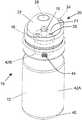
- FIG. 1Ashows an illustrative water bottle 10 according to an embodiment.
- the water bottle 10comprises a container 12 having a neck 14 , and a top cap 16 .
- the top cap 16can include a mouthpiece 18 with an opening 19 for extraction of a fluid, such as water, stored in the container 12 .
- the opening 19can be selectively opened and closed, e.g., by lifting and lowering the mouthpiece 18 .
- the top cap 16can have a maximum diameter that corresponds to the opening at the neck 14 of the container 12 .
- the mouthpiece 18can have a maximum diameter that is smaller than a maximum diameter of the top cap 16 .
- the water bottle 10can further include a mouthpiece cover assembly 20 , which can include a mouthpiece cover 22 configured to selectively cover the mouthpiece 18 and opening 19 .
- the mouthpiece cover 22can have a maximum diameter that is smaller than the maximum diameter of the top cap 16 .
- the maximum diameter of the mouthpiece cover 22is larger than the maximum diameter of the mouthpiece 18 .
- the mouthpiece cover assembly 20further includes a strap 24 and a securing mechanism 26 . The securing mechanism 26 can be secured to the container 12 and/or neck 14 of the water bottle 10 using any solution.
- the securing mechanism 26can comprise a ring having an inner diameter sized to fit around the neck 14 , but smaller than the maximum diameters of the container 12 and the top cap 16 .
- the strap 24can be permanently secured to both the mouthpiece cover 22 and the securing mechanism 26 using any solution, such as fabrication as one molded piece.
- the mouthpiece cover 22can be secured by a lock mechanism 17 located on a top surface of the top cap 16 when covering the mouthpiece 12 .
- the mouthpiece cover 22is further configured to disinfect the mouthpiece 18 , e.g., from organisms, such as bacteria, that can be transported from a person's mouth, using ultraviolet light.
- an embodiment of the mouthpiece cover 22can include one or more ultraviolet light sources 28 .
- the ultraviolet light source(s) 28can be positioned and oriented to illuminate at least a portion of the mouthpiece 18 with ultraviolet radiation when the mouthpiece cover 22 is covering the mouthpiece 18 .
- one or more ultraviolet light sources 28can be mounted to a top surface 23 A of the mouthpiece cover 22 and can be configured to direct ultraviolet radiation down toward a top surface of the mouthpiece 18 including the opening 19 .
- an embodiment of the mouthpiece cover 22can include one or more ultraviolet light sources mounted to a side surface 23 B of the mouthpiece cover 22 .
- Examples of an ultraviolet light source 28include, but are not limited to, ultraviolet LEDs, super luminescent LEDs, laser diodes, and/or the like.
- the ultraviolet light source 28can comprise an LED manufactured with one or more layers of materials selected from the group-III nitride material system (e.g., Al x In y Ga 1-x-y N, where 0 ⁇ x, y ⁇ 1, and x+y ⁇ 1 and/or alloys thereof).
- group-III nitride material systeme.g., Al x In y Ga 1-x-y N, where 0 ⁇ x, y ⁇ 1, and x+y ⁇ 1 and/or alloys thereof.
- any solution for mounting an ultraviolet light source 28 to the mouthpiece 18can be used.
- the ultraviolet light source 28can be embedded within the material of the mouthpiece 18 , e.g., with only a light emitting surface exposed.
- the ultraviolet light source 28can be adhered to a surface of the mouthpiece 18 using an ultraviolet transparent material, such as a fluoropolymer, polylactide (PLA), sapphire, fused silica, and/or the like.
- the ultraviolet light source 28can comprise one or more additional components (e.g., a wave guiding structure, a component for relocating and/or redirecting the ultraviolet light source 28 , etc.) to direct and/or deliver the emitted radiation to a particular location/area, in a particular direction, in a particular pattern, and/or the like.
- additional componentse.g., a wave guiding structure, a component for relocating and/or redirecting the ultraviolet light source 28 , etc.
- Illustrative wave guiding structuresinclude, but are not limited to: a wave guide; a plurality of ultraviolet fibers, each of which terminates at an opening; a diffuser; and/or the like.
- the ultraviolet light source 28can comprise a lens manufactured from an ultraviolet transparent material, which is designed to direct the ultraviolet radiation to one or more locations on the mouthpiece 18 .
- the mouthpiece cover 22can comprise a reflective parabolic mirror designed to collimate the ultraviolet radiation emitted by the ultraviolet light source 28 .
- these componentsare only illustrative of various possible components. To this extent, it is understood that other optical elements such as prisms, ultraviolet transparent windows, etc., can be employed.
- An ultraviolet light source 28can be configured to emit any type of ultraviolet radiation (e.g., radiation having a peak wavelength in a range of 10 nanometers to 400 nanometers) suitable for performing a desired disinfection of the mouthpiece 18 .
- the ultraviolet light emitted by the ultraviolet light source 28can have a peak wavelength selected to damage the DNA structure of any bacteria that may be present on the mouthpiece 18 .
- the ultraviolet light source 28can emit ultraviolet light in the UV-C wavelength range of approximately 250 nm to approximately 290 nm.
- the ultraviolet lighthas a peak wavelength in a range of 260 nanometers to 285 nanometers.
- the ultraviolet light source 28can emit ultraviolet radiation having a peak wavelength in the near-ultraviolet wavelength range of approximately 300 nanometers to 400 nanometers.
- the ultraviolet radiationcan have a peak wavelength in the UV-A wavelength range of approximately 315 nanometers to 400 nanometers.
- the peak wavelength emitted by the ultraviolet light source 28can be just outside the ultraviolet range, within the highest frequency range of the visible light spectrum, e.g., between 400 nanometers and 420 nanometers.
- a more particular embodiment of an ultraviolet light source 28can emit radiation having a peak wavelength in a range of 380 nanometers to 420 nanometers.
- the ultraviolet light sources 28can emit ultraviolet light of distinct peak wavelengths.
- the mouthpiece cover assembly 20includes all necessary components to enable operation of the ultraviolet light source 28 .
- the mouthpiece assembly 20can include a power source 30 , e.g., mounted to a side surface 23 B of the mouthpiece cover 22 .
- the power source 30can comprise, for example, a battery.
- the power source 30comprises a rechargeable battery.
- the mouthpiece cover assembly 20can include a mechanism for enabling the power source 30 to be recharged, such as a connector for forming an electrical connection with a recharging unit.
- the power source 30can be recharged via, for example, one or more solar cells, using a wireless recharging solution, and/or the like.
- a usercan selectively turn on and/or off power to the ultraviolet light source 28 .
- the mouthpiece cover assembly 20can include a control mechanism 32 , which enables the user to input a request to activate and/or deactivate the ultraviolet light source 28 .
- the control mechanism 32comprises a button, which when depressed, activates the ultraviolet light source 28 , e.g., for a predetermined fixed amount of time and/or until the control mechanism 32 is depressed again.
- the mouthpiece cover assembly 20includes an indicator as to whether the ultraviolet disinfection is occurring or is not occurring.
- the control mechanism 32can include a visible light that is on while the ultraviolet light source 28 is on and turns off when the ultraviolet light source 28 is off.
- an embodiment of the control mechanism 32comprises a button with a visible light source.
- a control mechanismcan use an audible or visual approach to provide the user with an approximate or exact amount of time remaining for the disinfection process to complete.
- the control mechanism 32can comprise multiple visual light sources or a visual light source having an adjustable brightness, which can be altered over time to indicate an approximate amount of time remaining.
- the control mechanism 32can include a visual (e.g., a countdown timer) or audible indication of time that is conveyed to the user.
- control mechanism 32and the operation thereof, is only illustrative.
- an embodimentcan activate the ultraviolet light source 28 , e.g., for a predetermined time period, when the mouthpiece cover 22 is secured to the lock mechanism 17 located on the top cap 16 .
- an embodimentcan prevent activation of the ultraviolet light source 28 via the control mechanism 32 when the mouthpiece cover 22 is not secured to the lock mechanism 17 .
- a rim 34 of the mouthpiece cover 22can be configured to generate a signal, close a switch, and/or the like, when the rim 34 is secured to the lock mechanism 17 .
- the rim 34can include one or more sensors, which are configured to generate a signal, close a switch, and/or the like, when a bottom of the rim 34 is in contact with the top surface of the top cap 16 .
- the rim 34 and/or sensor(s)can comprise a material whose electrical properties change when in contact with a material of the lock mechanism 17 and/or the top cap 16 .
- the mouthpiece cover assembly 20can comprise a control unit 36 (e.g., a microcontroller), which is configured to control operation of the ultraviolet light source 28 .
- a control unit 36can include logic for implementing a more complicated operation regime, e.g., determining a suitable intensity, duration, pattern, location, and/or the like, of the ultraviolet radiation, and operating the ultraviolet light source(s) 28 according to the determined operation regime.
- the operationcan be implemented with input from one or more sensors, such as the rim 34 and/or sensor(s) located thereon, and/or one or more control mechanisms 32 , which also can be included in the mouthpiece cover assembly 20 using any solution.
- the mouthpiece cover assembly 20can include various electrical connections 38 between the components included to enable operation of the ultraviolet light source 28 .
- the various devicesare shown and described as being mounted to the mouthpiece cover 22 , it is understood that one or more components can be mounted to a different portion of the mouthpiece cover assembly 20 .
- the power source 30 , control unit 36 , and/or control mechanism 32could be mounted on the strap 24 and/or the securing mechanism 26 .
- electrical connections 38 between the various componentscan be routed through (e.g., embedded in) the strap 24 and/or the securing mechanism 26 to the ultraviolet light source 28 .
- the ultraviolet light source 28can be mounted on the strap 24 and/or the securing mechanism 26 , with a wave guiding structure, such as optical fibers, routed through (e.g., embedded in) the strap 24 and/or the securing mechanism 26 to deliver light generated by the ultraviolet light source 28 to the mouthpiece 18 .
- a wave guiding structuresuch as optical fibers
- An internal surface of the mouthpiece cover 22 , an outer surface of the mouthpiece 18 , and/or a top surface of the top cap 16can be configured to contain the ultraviolet radiation within a region defined thereby. In an embodiment, one or more of these surfaces is configured to improve recycling of the ultraviolet radiation within the region. In an embodiment, one or more of such surfaces is capable of reflecting the ultraviolet radiation.
- such a reflective surfacecan comprise polished aluminum, a fluoropolymer, such as ethylene fluorinated ethylene-propylene (EFEP), expanding polytetrafluoroethylene (ePTFE) membrane (e.g., GORE® DRP® Diffuse Reflector Material), polytetrafluoroethylene (PTFE, e.g., Teflon®), and/or the like.
- EFEPethylene fluorinated ethylene-propylene
- ePTFEexpanding polytetrafluoroethylene
- PTFEpolytetrafluoroethylene
- Teflon®polytetrafluoroethylene
- one or more of the internal surface of the mouthpiece cover 22 , the outer surface of the mouthpiece 18 , and/or the top surface of the top cap 16can include a material transparent to the ultraviolet radiation.
- a transparent layercan be located adjacent to and on a side of a reflective layer of material forming a region in which the ultraviolet light is emitted.
- the transparent layercan be configured to provide wave guiding.
- Such a surfacecan comprise any suitable ultraviolet transparent material, such as SiO 2 , Al 3 O 3 , CaF 2 , MgF 3 , HfO 2 , and/or the like.
- such a surfacecan also comprise a fluoropolymer.
- each surface exposed to the ultraviolet radiation generated by the ultraviolet light source 28can be formed of a material that is suitable for use in conjunction with the ultraviolet radiation, e.g., will not be modified in a potentially hazardous manner.
- the internal surfacecan comprise a material such as stainless steel, quartz window(s), and/or the like, which are capable of withstanding exposure to such radiation.
- FIG. 2shows an illustrative water bottle 10 according to another embodiment.
- the water bottle 10can include a mouthpiece cover assembly 20 , which can be configured as described in conjunction with FIGS. 1A and 1B .
- the water bottle 10includes a bottom member 40 with an ultraviolet light source 28 located thereon.
- the ultraviolet light source 28can be configured to emit ultraviolet light that is directed into an interior of the container 12 .
- the bottom member 40can comprise a detachable bottom surface for an interior volume formed by the container 12 .
- the container 12can include a bottom surface through which ultraviolet radiation generated by the ultraviolet light source 28 is directed.
- the ultraviolet lightcan be used to, for example, disinfect a fluid, such as water, located within the interior of the container 12 and/or disinfect one or more surfaces defining the interior of the container 12 .
- the top cap 16can include one or more ultraviolet light sources 28 configured to emit ultraviolet light directed into the interior of the container 12 and be configured similar to the bottom member 40 .
- the container 12can be configured to include one or more ultraviolet light sources 28 .
- a bottom of the container 12can include an ultraviolet light source 28 without requiring a removable bottom member 40 .
- embodiments of a water bottle described hereincan be fabricated with any combination of one or more of: a bottom member 40 , a mouthpiece cover assembly 20 , a container 12 , and/or a top cap 16 , including one or more ultraviolet light sources 28 and/or one or more components for operating the ultraviolet light source(s) 28 to disinfect one or more surfaces of the water bottle 10 and/or a fluid contained therein.
- the ultraviolet light sources 28can be operated autonomously or together.
- operation of an ultraviolet light source on the mouthpiece cover assembly 20can be separate from operation of any other ultraviolet light source(s) on the water bottle 10 .
- the ultraviolet light source 28can be configured similar to the ultraviolet light source described in conjunction with FIGS. 1A and 1B .
- the bottom member 40can include one or more of the additional components described in conjunction with the mouthpiece cover assembly 20 , such as: a power source 30 ; component(s), such as a control unit 36 , wave guiding structures, and/or the like, to direct and/or deliver the emitted radiation to a particular location/area, in a particular direction, in a particular pattern, etc.; a control mechanism 32 for interfacing with a user; etc.
- the bottom member 40can be removable. To this extent, the bottom member 40 can be separately washed and/or enable easier washing of the interior surfaces of the container 12 .
- the container 12can include a bottom fabricated of a material transparent to ultraviolet radiation. Any of the ultraviolet transparent materials described herein can be used to fabricate a bottom of the container 12 .
- an interior surface of the container 12 and/or an interior surface of the top cap 16can be formed of a material and/or include one or more structures configured to contain the ultraviolet radiation within the container 12 . In an embodiment, one or more of these surfaces is configured to improve recycling of the ultraviolet radiation within the container 12 , e.g., by including ultraviolet transparent and/or reflective materials, one or more wave guiding structures, and/or the like.
- the bottom of the container 12 and the bottom member 40can be configured to be removably secured to one another.
- the bottom of the container 12 and the bottom member 40can include complementary screw threads.
- a magnetic and/or tension coupling mechanism, and/or the likecan be utilized to removably secure the bottom member 40 to the container 12 in a desired location.
- the bottom member 40can include one or more sensors configured to prevent the ultraviolet light source 28 from emitting ultraviolet light when the bottom member 40 is not secured to the bottom of the container 12 .
- the bottom member 40can include one or more sensors configured to emit a signal, close a switch, and/or the like, when in contact with the bottom of the container 12 .
- the container 12can include one or more sensors configured to prevent the ultraviolet light source 28 from emitting ultraviolet light when the top cap 16 is not secured to the container 12 .
- the neck 14 of the container 12can include a sensor which emits a signal, close a switch, and/or the like, when the top cap 16 is attached thereto. While not shown for clarity, it is understood that the container 12 and the bottom member 40 can include the required wiring embedded therein to enable operation of the ultraviolet light source 28 .
- a water bottle described hereinincludes one or more additional light sources and/or sensors.
- an embodiment of the water bottlecan include one or more visible light sources, e.g., to provide information regarding a status of an ultraviolet disinfection to a user.
- an embodiment of the water bottlecan include one or more sensors for determining a level of and/or location of contamination on a surface of the water bottle and/or in the fluid contained therein.
- an embodiment of a water bottle described hereincan include a visible or infrared light source, which can be operated by a microcontroller to induce fluorescent excitation in a contaminant which may be present on the surface, e.g., of the mouthpiece, an interior surface of the container, an interior surface of the top cover, and/or the like.
- the water bottlecan further include a set of sensors configured to sense the fluorescent radiation, which can be correlated with a level of contamination on the corresponding surface.
- the set of sensorscan provide fluorescent radiation data to a control unit, which can process the data to determine whether an ultraviolet treatment of the surface is required and/or modify one or more of an intensity, duration, location, etc., of the ultraviolet radiation in response.
- a set of ultraviolet light sources 28can emit UV-A and/or visible light in a range between 380-420 nanometers. Such radiation can increase the presence of reactive oxygen species (ROS) within the fluid, which can contribute to the decay of the microorganisms.
- ROSreactive oxygen species
- an ultraviolet light source 28 that emits UV-A and/or visible radiationcan be combined with a photocatalyst to increase hydroxyl group radicals and/or ROS within the fluid to suppress microorganism growth.
- the photocatalystcan comprise any suitable photocatalyst, such as for example, TiO 2 , copper, silver, copper/silver particles, platinum/palladium particles, etc., and can be applied to the inner surfaces of the container 14 using any solution.
- the inner surfaces of the container 14can comprise sapphire with platinum/palladium decoration.
- the water bottle 10can include instructions for the user to shake the water bottle 10 during the disinfection. Additionally, the water bottle 10 can include one or more additional components to improve mixing. For example, a set of mixing elements can be included within the container 12 . Furthermore, one or more ultraviolet light sources 28 can be positioned within the fluid, e.g., via structure that extends into the interior of the container 12 and includes an ultraviolet transparent material that encapsulates the ultraviolet light source(s) 28 from the fluid.
- FIG. 3shows another illustrative water bottle 10 according to an embodiment.
- the mouthpiece cover assembly 20includes a larger, semi-spherical mouthpiece cover 22 , with an ultraviolet light source 28 located thereon.
- a larger mouthpiece cover 22can be beneficial for improved disinfection of the mouthpiece 18 .
- the mouthpiece cover assembly 20can include features and/or other components for operating the ultraviolet light source 28 as shown and/or described herein.
- the container 12can include two storage regions 42 A, 42 B.
- the storage regions 42 A, 42 Bcan be separated by a structure that restricts the flow of fluid between the storage regions 42 A, 42 B to one or more one way valves 44 .
- Each one way valve 44can be configured to allow fluid to flow from the storage region 42 A to the storage region 42 B, but not the reverse.
- the storage region 42 Acan comprise a larger volume than the volume of fluid stored in the storage region 42 B, while the storage region 42 B can be fluidly connected to the mouthpiece 18 .
- fluid within the storage region 42 Bmay interact with a user's mouth and, as a result, may be contaminated by the user. However, any such contamination will remain confined to the storage region 42 B and the fluid located therein.
- the larger volume of fluid stored in the storage region 42 Acan remain uncontaminated.
- the smaller volume of fluid located in the storage region 42 Bcan be discarded without discarding the larger volume of fluid located in the storage region 42 A.
- a usercan remove a cover 21 of the storage region 42 B and pour out the fluid.
- the one way valve 44can remain closed and only allow fluid to pass there through in response to additional pressure being generated (e.g., by squeezing the container 12 ).
- the usercan disassemble the storage region 42 B from the storage region 42 A and pour out the fluid before reassembling the regions 42 A, 42 B.
- the one way valve 44in addition to restricting the flow of fluid, can include a filter, which can be configured to remove large scale particles that may be present in the fluid stored in the region 42 A prior to the fluid entering the storage region 42 B.
- An embodiment of the water bottle 10can be configured to disinfect the fluid and/or surfaces of the storage region 42 B.
- a capthe cover 21 covering the storage region 42 Bcan include a set of ultraviolet light sources 29 . While not shown for clarity, it is understood that the ultraviolet light sources 29 and/or the storage region 42 B can include features and/or other components for operating the ultraviolet light sources 29 as shown and/or described herein in order to disinfect the fluid and/or surfaces of the storage region 42 B.
- An embodiment of the water bottle 10can include a bottom member 40 , which can disinfect a fluid and/or one or more surfaces of the interior of the container 12 .
- the bottom member 40can be configured to disinfect the fluid stored within the storage region 42 A and/or the interior surfaces of the storage region 42 A and can be configured as described herein.
- one or both storage regions 42 A, 42 Bcontains a photocatalyst, which can improve disinfection as described herein.
- access to the storage region 42 Acan be obtained via removing the bottom member 40 .
- the container 12can comprise two distinct portions, one for each storage region 42 A, 42 B, which can be attached and selectively detached to expose the storage region 42 A using any attachment mechanism, e.g., complementary screw threads.
- an embodiment of the water bottle 10can be implemented without the bottom member 40 including an ultraviolet light source.
- the fluid placed in the storage region 42 Acan be known to be safe for consumption.
- a popup mouthpiece 18 as shown hereinis only illustrative of various mouthpiece configurations that can be disinfected using a solution described herein.
- the placement of the ultraviolet light source(s)can be selected based on the location of the opening 19 and/or orientation of the mouthpiece when placed in a stored configuration to direct the ultraviolet radiation to the desired location(s).
- FIG. 4shows an illustrative top cover 50 with a retractable mouthpiece 52 (e.g., a retractable wide straw) according to an embodiment.
- the top cover 50includes a top cap 54 , which can be removably attached to a top of a container 12 of a water bottle using any solution, e.g., complementary screw threads.
- the top cover 50further includes an integrated mouthpiece cover assembly, which includes a rotatable mouthpiece cover 56 .
- To retract the mouthpiece 52 when not in usethe user can first rotate the mouthpiece 52 in the direction shown and then rotate the mouthpiece cover 56 in the direction shown. Once fully lowered, the mouthpiece cover 56 can be held in place by a latch mechanism (not shown).
- a button 58which causes the latch mechanism to release and the mouthpiece cover 56 and retractable mouthpiece 52 to rotate to their illustrated positions (e.g., via spring mechanisms).
- the top cover 50further includes a set of ultraviolet light sources 28 A, 28 B, which are configured to irradiate the retracted mouthpiece 52 to disinfect the mouthpiece 52 .
- the top cover 50can include various other features and/or other components for operating the ultraviolet light sources 28 A, 28 B as shown and/or described herein in order to disinfect the mouthpiece 52 .
- the top cover 50can include a control unit that operates the ultraviolet light sources 28 A, 28 B when the mouthpiece 52 is retracted and secured by the mouthpiece cover 56 .
- the control unitcan receive an indication that the mouthpiece cover 56 is secured from one or more sensors, e.g., associated with the latch mechanism.
- the control unitin response to the latch mechanism being released, e.g., by depression of the button 58 , the control unit can turn off the ultraviolet light sources 28 A, 28 B, if necessary.
- the button 58includes a visible indicator indicating that an ultraviolet treatment is being performed on the mouthpiece 52 .
- the mouthpiece 52 , mouthpiece cover 56 and top surface of the top cap 54can form an enclosure within which the ultraviolet radiation emitted by the ultraviolet light sources 28 A, 28 B is shone.
- Each of these componentscan be fabricated of a suitable material, which can facilitate containment and/or recycling of the ultraviolet light therein.
- the mouthpiece 52is fabricated of an ultraviolet transparent material, which allows ultraviolet light to penetrate the outer walls of the mouthpiece 52 to disinfect an interior region defined by the opening 59 .
- one or more ultraviolet light sourcescan be located to direct ultraviolet radiation directly into the opening 59 .
- an embodimentcan comprise a control unit that can turn on the disinfection process, e.g., after each use of the water bottle.
- the control unitcan determine use of the water bottle using data from any of various possible sensors. For example, the use can be determined by sensing an opening of a cover for the mouthpiece, a change in bottle orientation, or other indicators of use, such as changes in a weight of the fluid stored within the water bottle.
- the control unitcan adjust the radiation intensity and/or duration based on one or more of: the amount of water in the bottle, the frequency of the use of the water bottle, data collected by fluorescent sensors, and/or the like.
- the term “set”means one or more (i.e., at least one) and the phrase “any solution” means any now known or later developed solution.
- the singular forms “a,” “an,” and “the”include the plural forms as well, unless the context clearly indicates otherwise.
- the terms “comprises,” “includes,” “has,” and related forms of each, when used in this specification,specify the presence of stated features, but do not preclude the presence or addition of one or more other features and/or groups thereof. It is understood that, unless otherwise specified, each value is approximate and each range of values included herein is inclusive of the end values defining the range.
- the term “approximately”means a reasonable amount of deviation of the modified term such that the end result is not meaningfully changed. In an embodiment, approximately is inclusive of values within +/ ⁇ ten percent of the stated value when this deviation does not result in a meaningful change to the modified value, term, range, etc.
Landscapes
- Health & Medical Sciences (AREA)
- Engineering & Computer Science (AREA)
- Mechanical Engineering (AREA)
- General Health & Medical Sciences (AREA)
- Pediatric Medicine (AREA)
- Life Sciences & Earth Sciences (AREA)
- Animal Behavior & Ethology (AREA)
- Epidemiology (AREA)
- Public Health (AREA)
- Veterinary Medicine (AREA)
- Physical Water Treatments (AREA)
- Apparatus For Disinfection Or Sterilisation (AREA)
- Physics & Mathematics (AREA)
- Optics & Photonics (AREA)
- Details Of Rigid Or Semi-Rigid Containers (AREA)
Abstract
Description
Claims (20)
Priority Applications (2)
| Application Number | Priority Date | Filing Date | Title |
|---|---|---|---|
| US16/176,336US11173221B2 (en) | 2017-10-31 | 2018-10-31 | Ultraviolet disinfection for a water bottle |
| US17/526,185US20220072169A1 (en) | 2017-10-31 | 2021-11-15 | Ultraviolet Disinfection for a Water Bottle |
Applications Claiming Priority (2)
| Application Number | Priority Date | Filing Date | Title |
|---|---|---|---|
| US201762579876P | 2017-10-31 | 2017-10-31 | |
| US16/176,336US11173221B2 (en) | 2017-10-31 | 2018-10-31 | Ultraviolet disinfection for a water bottle |
Related Child Applications (1)
| Application Number | Title | Priority Date | Filing Date |
|---|---|---|---|
| US17/526,185ContinuationUS20220072169A1 (en) | 2017-10-31 | 2021-11-15 | Ultraviolet Disinfection for a Water Bottle |
Publications (2)
| Publication Number | Publication Date |
|---|---|
| US20190125907A1 US20190125907A1 (en) | 2019-05-02 |
| US11173221B2true US11173221B2 (en) | 2021-11-16 |
Family
ID=66245907
Family Applications (2)
| Application Number | Title | Priority Date | Filing Date |
|---|---|---|---|
| US16/176,336ActiveUS11173221B2 (en) | 2017-10-31 | 2018-10-31 | Ultraviolet disinfection for a water bottle |
| US17/526,185PendingUS20220072169A1 (en) | 2017-10-31 | 2021-11-15 | Ultraviolet Disinfection for a Water Bottle |
Family Applications After (1)
| Application Number | Title | Priority Date | Filing Date |
|---|---|---|---|
| US17/526,185PendingUS20220072169A1 (en) | 2017-10-31 | 2021-11-15 | Ultraviolet Disinfection for a Water Bottle |
Country Status (1)
| Country | Link |
|---|---|
| US (2) | US11173221B2 (en) |
Cited By (6)
| Publication number | Priority date | Publication date | Assignee | Title |
|---|---|---|---|---|
| US11945735B2 (en) | 2018-03-31 | 2024-04-02 | Sensor Electronic Technology, Inc. | Ultraviolet irradiation of a flowing fluid |
| US12128149B2 (en) | 2018-01-31 | 2024-10-29 | Sensor Electronic Technology, Inc. | Humidifier disinfection using ultraviolet light |
| USD1050801S1 (en) | 2022-12-16 | 2024-11-12 | Yeti Coolers, Llc | Lid |
| USD1050803S1 (en) | 2022-12-16 | 2024-11-12 | Yeti Coolers, Llc | Lid |
| USD1080747S1 (en) | 2022-12-16 | 2025-06-24 | Yeti Coolers, Llc | Lid |
| US12402570B2 (en) | 2016-07-26 | 2025-09-02 | Sensor Electronic Technology, Inc. | Radiation-based mildew control |
Families Citing this family (8)
| Publication number | Priority date | Publication date | Assignee | Title |
|---|---|---|---|---|
| US11375595B2 (en) | 2016-09-30 | 2022-06-28 | Sensor Electronic Technology, Inc. | Controlling ultraviolet intensity over a surface of a light sensitive object |
| US10881755B2 (en) | 2017-12-31 | 2021-01-05 | Sensor Electronic Technology, Inc. | Ultraviolet illumination with optical elements |
| US11608279B2 (en) | 2018-02-28 | 2023-03-21 | Sensor Electronic Technology, Inc. | Ultraviolet irradiation of fluids |
| US10881751B2 (en) | 2018-03-31 | 2021-01-05 | Sensor Electronic Technology, Inc. | Ultraviolet irradiation of food handling instruments |
| US11027319B2 (en) | 2018-03-31 | 2021-06-08 | Sensor Electronic Technology, Inc. | Illumination using multiple light sources |
| CN110236291B (en)* | 2019-08-02 | 2024-02-02 | 江苏厚睦莱照明科技有限公司 | Military kettle |
| CN111513526A (en)* | 2020-05-18 | 2020-08-11 | 上海应用技术大学 | A deep ultraviolet LED sterilization water cup |
| US12274801B2 (en)* | 2022-03-30 | 2025-04-15 | Delcina Augustin | Spirometer sterilizing assembly |
Citations (74)
| Publication number | Priority date | Publication date | Assignee | Title |
|---|---|---|---|---|
| US5292021A (en)* | 1989-04-28 | 1994-03-08 | Lyon Christopher J | Holder for liquid containing package |
| US5919365A (en)* | 1997-07-21 | 1999-07-06 | Collette; Daniel | Filter device for drinking container |
| US6004460A (en)* | 1998-03-19 | 1999-12-21 | Seychelle Environmental Technology, Inc. | Portable water filtration bottle |
| US6565743B1 (en)* | 1999-08-31 | 2003-05-20 | Kimberly-Clark Worldwide, Inc. | Portable purification container with cumulative use indicator |
| US20060165571A1 (en)* | 2005-01-24 | 2006-07-27 | Seon Kim S | Nipple overcap having sterilizer |
| US20080203005A1 (en)* | 2007-01-25 | 2008-08-28 | 350 Cambridge Partners, Llc | Water filter device for use with individual containers |
| US7537141B1 (en)* | 2005-07-26 | 2009-05-26 | Rexam Closure Systems Inc. | Dispensing closure and package |
| US7553456B2 (en) | 2006-03-02 | 2009-06-30 | Sensor Electronic Technology, Inc. | Organism growth suppression using ultraviolet radiation |
| US7634996B2 (en) | 2006-02-14 | 2009-12-22 | Sensor Electronic Technology, Inc. | Ultraviolet radiation sterilization |
| US20110278206A1 (en)* | 2008-03-18 | 2011-11-17 | Rubbermaid Inc. | Drinking Container and Filter Assembly |
| US8277734B2 (en) | 2008-05-12 | 2012-10-02 | Sensor Electronic Technology, Inc. | Biological activity monitoring and/or suppression |
| US20130048545A1 (en) | 2011-08-23 | 2013-02-28 | Maxim S. Shatalov | Water Disinfection Using Deep Ultraviolet Light |
| US20130214007A1 (en)* | 2012-02-10 | 2013-08-22 | Armond Simonian | Water bottle with check valve |
| US20130319915A1 (en)* | 2012-05-30 | 2013-12-05 | Floz, Inc. | Water Bottle with Flow Meter |
| US20140202962A1 (en) | 2013-01-18 | 2014-07-24 | Sensor Electronic Technology, Inc. | Ultraviolet Fluid Disinfection System with Feedback Sensor |
| US20140202948A1 (en)* | 2013-01-24 | 2014-07-24 | Xiaohang Li | Portable Liquid Purifying Apparatus |
| US20150053624A1 (en)* | 2013-08-21 | 2015-02-26 | Hydro-Photon, Inc. | Portable water purification system using one or more low output power uv light sources |
| US8975596B1 (en)* | 2012-07-20 | 2015-03-10 | Meridian Design, Inc. | Water purifying drink containers |
| US8980178B2 (en) | 2009-05-23 | 2015-03-17 | Sensor Electronic Technology, Inc. | Medium treatment using ultraviolet light |
| US9006680B2 (en) | 2013-03-18 | 2015-04-14 | Sensor Electronic Technology, Inc. | Ultraviolet disinfection case |
| US9034271B2 (en) | 2012-08-28 | 2015-05-19 | Sensor Electronics Technology, Inc. | Storage device including ultraviolet illumination |
| US9061082B2 (en) | 2012-04-16 | 2015-06-23 | Sensor Electronic Technology, Inc. | Ultraviolet-based sterilization |
| US20150217011A1 (en)* | 2013-03-18 | 2015-08-06 | Sensor Electronic Technology, Inc. | Ultraviolet Disinfection Case |
| US9138499B2 (en) | 2012-12-31 | 2015-09-22 | Sensor Electronic Technology, Inc. | Electronic gadget disinfection |
| US9179703B2 (en) | 2012-08-28 | 2015-11-10 | Sensor Electronic Technology, Inc. | Ultraviolet system for disinfection |
| US20160031720A1 (en)* | 2014-08-01 | 2016-02-04 | QuenchWorks, LLC | Roll-up water bottle with closure/filter assembly |
| US20160107904A1 (en)* | 2013-05-22 | 2016-04-21 | Merck Patent Gmbh | Biocidal Purification Device |
| US20160114186A1 (en) | 2014-10-28 | 2016-04-28 | Sensor Electronic Technology, Inc. | Adhesive Device with Ultraviolet Element |
| US20160166094A1 (en)* | 2014-05-02 | 2016-06-16 | Munchkin, Inc. | Bite proof straw assembly |
| US20160355412A1 (en)* | 2015-06-08 | 2016-12-08 | Rayvio Corporation | Ultraviolet disinfection system |
| US9572903B2 (en) | 2014-10-15 | 2017-02-21 | Sensor Electronic Technology, Inc. | Ultraviolet-based detection and sterilization |
| US20170057842A1 (en) | 2015-09-01 | 2017-03-02 | Sensor Electronic Technology, Inc. | Fluid Disinfection Using Ultraviolet Light |
| US20170057841A1 (en)* | 2015-08-27 | 2017-03-02 | aqUV, LLC | Liquid purification system |
| US20170100495A1 (en) | 2012-08-28 | 2017-04-13 | Sensor Electronic Technology, Inc. | Storage Device Including Ultraviolet Illumination |
| US9687577B2 (en) | 2014-09-13 | 2017-06-27 | Sensor Electronic Technology, Inc. | Ultraviolet illuminator for footwear treatment |
| US20170189711A1 (en) | 2015-12-31 | 2017-07-06 | Sensor Electronic Technology, Inc. | Medical Device with Radiation Delivery |
| US9707307B2 (en) | 2012-08-28 | 2017-07-18 | Sensor Electronic Technology, Inc. | Ultraviolet system for disinfection |
| US9718706B2 (en) | 2014-06-03 | 2017-08-01 | Sensor Electronic Technology, Inc. | Ultraviolet transparent enclosure |
| US9724441B2 (en) | 2012-08-28 | 2017-08-08 | Sensor Electronic Technology, Inc. | Storage device including target UV illumination ranges |
| US20170245616A1 (en) | 2016-02-29 | 2017-08-31 | Sensor Electronic Technology, Inc. | Ultraviolet Razor Blade Treatment |
| US20170245527A1 (en) | 2016-02-29 | 2017-08-31 | Sensor Electronic Technology, Inc. | Disinfection of Grain using Ultraviolet Radiation |
| US9750830B2 (en) | 2012-08-28 | 2017-09-05 | Sensor Electronic Technology, Inc. | Multi wave sterilization system |
| US9757486B2 (en) | 2014-11-06 | 2017-09-12 | Sensor Electronic Technology, Inc. | Ultraviolet-based bathroom surface sanitization |
| US20170280737A1 (en)* | 2015-03-27 | 2017-10-05 | Rayvio Corporation | Device for uv-led liquid monitoring and treatment |
| US20170281812A1 (en) | 2016-03-31 | 2017-10-05 | Sensor Electronic Technology, Inc. | Treatment Of Fluid Transport Conduit With Ultraviolet Radiation |
| US20170290934A1 (en) | 2016-04-07 | 2017-10-12 | Sensor Electronic Technology, Inc. | Ultraviolet Surface Illumination System |
| US9802840B2 (en) | 2013-07-08 | 2017-10-31 | Sensor Electronic Technology, Inc. | Ultraviolet water disinfection system |
| WO2017185217A1 (en)* | 2016-04-25 | 2017-11-02 | 圆融健康科技(深圳)有限公司 | Sterilization cover, storage apparatus, water bottle, milk bottle, medicine bottle, and cosmetic bottle |
| US20170368215A1 (en) | 2012-08-28 | 2017-12-28 | Sensor Electronic Technology, Inc. | Storage Device Including Ultraviolet Illumination |
| US9878061B2 (en) | 2012-08-28 | 2018-01-30 | Sensor Electronic Technology, Inc. | Ultraviolet system for disinfection |
| US20180028700A1 (en) | 2016-07-26 | 2018-02-01 | Sensor Electronic Technology, Inc. | Ultraviolet-Based Mildew Control |
| US9919068B2 (en) | 2012-08-28 | 2018-03-20 | Sensor Electronic Technology, Inc. | Storage device including ultraviolet illumination |
| US20180092308A1 (en) | 2016-09-30 | 2018-04-05 | Sensor Electronic Technology, Inc. | Controlling Ultraviolet Intensity Over a Surface of a Light Sensitive Object |
| US20180104368A1 (en) | 2012-04-16 | 2018-04-19 | Sensor Electronic Technology, Inc. | Ultraviolet-Based Sterilization |
| US20180117194A1 (en) | 2014-10-15 | 2018-05-03 | Sensor Electronic Technology, Inc. | Ultraviolet-Based Detection and Sterilization |
| US9974877B2 (en) | 2012-12-31 | 2018-05-22 | Sensor Electronic Technology, Inc. | Electronic gadget disinfection |
| US9981051B2 (en) | 2012-08-28 | 2018-05-29 | Sensor Electronic Technology, Inc. | Ultraviolet gradient sterilization, disinfection, and storage system |
| US9987383B2 (en) | 2015-05-07 | 2018-06-05 | Sensor Electronic Technology, Inc. | Medical device treatment |
| US9999782B2 (en) | 2012-04-16 | 2018-06-19 | Sensor Electronic Technology, Inc. | Ultraviolet-based sterilization |
| US10004821B2 (en) | 2015-10-13 | 2018-06-26 | Sensor Electronic Technology, Inc. | Ultraviolet treatment of light absorbing liquids |
| US20180185529A1 (en) | 2016-12-29 | 2018-07-05 | Sensor Electronic Technology, Inc. | Ultraviolet Illuminator for Object Disinfection |
| US20180194645A1 (en)* | 2017-01-12 | 2018-07-12 | Industrial Technology Research Institute | Purifying device |
| US10040699B2 (en) | 2013-07-08 | 2018-08-07 | Sensor Electronics Technology, Inc. | Ultraviolet water disinfection system |
| US20180221521A1 (en) | 2012-08-28 | 2018-08-09 | Sensor Electronic Technology, Inc. | Multi Wave Sterilization System |
| US20180243458A1 (en) | 2012-08-28 | 2018-08-30 | Sensor Electronic Technology, Inc. | Storage Device Including Ultraviolet Illumination |
| US10099944B2 (en) | 2014-06-03 | 2018-10-16 | Sensor Electronic Technology, Inc. | Ultraviolet transparent enclosure |
| US20180339075A1 (en) | 2017-05-26 | 2018-11-29 | Sensor Electronic Technology, Inc. | Surface Treatment with Ultraviolet Light |
| US20190030477A1 (en) | 2017-07-31 | 2019-01-31 | Sensor Electronic Technology, Inc. | Ultraviolet Treatment of Volatile Organic Compounds |
| US20190038008A1 (en)* | 2017-08-02 | 2019-02-07 | An-Jen LEE | Storage bottle with filtration and disinfection effects |
| US20190090998A1 (en)* | 2017-09-25 | 2019-03-28 | Dentsply Sirona Inc. | Method and arrangement for cleaning of a canal |
| US20190100718A1 (en) | 2017-09-30 | 2019-04-04 | Sensor Electronic Technology, Inc. | Ultraviolet Irradiation of Fluids |
| US20190099613A1 (en) | 2017-09-30 | 2019-04-04 | Sensor Electronic Technology, Inc. | Wearable Ultraviolet Light Phototherapy Device |
| US20190100445A1 (en) | 2017-09-30 | 2019-04-04 | Sensor Electronic Technology, Inc. | Ultraviolet Irradiation of Aquatic Environment |
| US20190117811A1 (en) | 2017-10-25 | 2019-04-25 | Sensor Electronic Technology, Inc. | Illuminator with Ultraviolet and Blue-Ultraviolet Light Source |
Family Cites Families (7)
| Publication number | Priority date | Publication date | Assignee | Title |
|---|---|---|---|---|
| JP2001238936A (en)* | 2000-02-26 | 2001-09-04 | Market Bureinzu:Kk | Screw cap for nursing bottle |
| KR200328679Y1 (en)* | 2003-05-02 | 2003-10-01 | 김상선 | UV Sterilizer Bottle Overcap |
| KR100447287B1 (en)* | 2003-09-30 | 2004-09-07 | (주)유비코 | a pacifier sterilizer for a baby |
| CN202950971U (en)* | 2012-10-24 | 2013-05-29 | 北京六同志远科技有限公司 | Ultraviolet-light emitting diode (UV-LED) sterilization disinfection cover |
| US20140263377A1 (en)* | 2013-03-13 | 2014-09-18 | Juan Marco Jullian Olmedo | Liquid storage closure device with integrated straw |
| KR20160060286A (en)* | 2014-11-20 | 2016-05-30 | (주)위더스아이엔씨코리아 | Portable apparatus for sterilization and disinfection of feeding bottle |
| CN206198314U (en)* | 2016-07-05 | 2017-05-31 | 济宁市丰鹏工程设备有限公司 | A kind of feeding bottle of long-acting bactericidal |
- 2018
- 2018-10-31USUS16/176,336patent/US11173221B2/enactiveActive
- 2021
- 2021-11-15USUS17/526,185patent/US20220072169A1/enactivePending
Patent Citations (78)
| Publication number | Priority date | Publication date | Assignee | Title |
|---|---|---|---|---|
| US5292021A (en)* | 1989-04-28 | 1994-03-08 | Lyon Christopher J | Holder for liquid containing package |
| US5919365A (en)* | 1997-07-21 | 1999-07-06 | Collette; Daniel | Filter device for drinking container |
| US6004460A (en)* | 1998-03-19 | 1999-12-21 | Seychelle Environmental Technology, Inc. | Portable water filtration bottle |
| US6565743B1 (en)* | 1999-08-31 | 2003-05-20 | Kimberly-Clark Worldwide, Inc. | Portable purification container with cumulative use indicator |
| US20060165571A1 (en)* | 2005-01-24 | 2006-07-27 | Seon Kim S | Nipple overcap having sterilizer |
| US7537141B1 (en)* | 2005-07-26 | 2009-05-26 | Rexam Closure Systems Inc. | Dispensing closure and package |
| US7634996B2 (en) | 2006-02-14 | 2009-12-22 | Sensor Electronic Technology, Inc. | Ultraviolet radiation sterilization |
| US7553456B2 (en) | 2006-03-02 | 2009-06-30 | Sensor Electronic Technology, Inc. | Organism growth suppression using ultraviolet radiation |
| US20080203005A1 (en)* | 2007-01-25 | 2008-08-28 | 350 Cambridge Partners, Llc | Water filter device for use with individual containers |
| US20110278206A1 (en)* | 2008-03-18 | 2011-11-17 | Rubbermaid Inc. | Drinking Container and Filter Assembly |
| US8277734B2 (en) | 2008-05-12 | 2012-10-02 | Sensor Electronic Technology, Inc. | Biological activity monitoring and/or suppression |
| US8980178B2 (en) | 2009-05-23 | 2015-03-17 | Sensor Electronic Technology, Inc. | Medium treatment using ultraviolet light |
| US20130048545A1 (en) | 2011-08-23 | 2013-02-28 | Maxim S. Shatalov | Water Disinfection Using Deep Ultraviolet Light |
| US20130214007A1 (en)* | 2012-02-10 | 2013-08-22 | Armond Simonian | Water bottle with check valve |
| US20180104368A1 (en) | 2012-04-16 | 2018-04-19 | Sensor Electronic Technology, Inc. | Ultraviolet-Based Sterilization |
| US9061082B2 (en) | 2012-04-16 | 2015-06-23 | Sensor Electronic Technology, Inc. | Ultraviolet-based sterilization |
| US9999782B2 (en) | 2012-04-16 | 2018-06-19 | Sensor Electronic Technology, Inc. | Ultraviolet-based sterilization |
| US20130319915A1 (en)* | 2012-05-30 | 2013-12-05 | Floz, Inc. | Water Bottle with Flow Meter |
| US8975596B1 (en)* | 2012-07-20 | 2015-03-10 | Meridian Design, Inc. | Water purifying drink containers |
| US9034271B2 (en) | 2012-08-28 | 2015-05-19 | Sensor Electronics Technology, Inc. | Storage device including ultraviolet illumination |
| US9707307B2 (en) | 2012-08-28 | 2017-07-18 | Sensor Electronic Technology, Inc. | Ultraviolet system for disinfection |
| US9724441B2 (en) | 2012-08-28 | 2017-08-08 | Sensor Electronic Technology, Inc. | Storage device including target UV illumination ranges |
| US20170100495A1 (en) | 2012-08-28 | 2017-04-13 | Sensor Electronic Technology, Inc. | Storage Device Including Ultraviolet Illumination |
| US9919068B2 (en) | 2012-08-28 | 2018-03-20 | Sensor Electronic Technology, Inc. | Storage device including ultraviolet illumination |
| US9179703B2 (en) | 2012-08-28 | 2015-11-10 | Sensor Electronic Technology, Inc. | Ultraviolet system for disinfection |
| US20180243458A1 (en) | 2012-08-28 | 2018-08-30 | Sensor Electronic Technology, Inc. | Storage Device Including Ultraviolet Illumination |
| US9795699B2 (en) | 2012-08-28 | 2017-10-24 | Sensor Electronic Technology, Inc. | Storage device including target UV illumination ranges |
| US20180221521A1 (en) | 2012-08-28 | 2018-08-09 | Sensor Electronic Technology, Inc. | Multi Wave Sterilization System |
| US9878061B2 (en) | 2012-08-28 | 2018-01-30 | Sensor Electronic Technology, Inc. | Ultraviolet system for disinfection |
| US20170368215A1 (en) | 2012-08-28 | 2017-12-28 | Sensor Electronic Technology, Inc. | Storage Device Including Ultraviolet Illumination |
| US9750830B2 (en) | 2012-08-28 | 2017-09-05 | Sensor Electronic Technology, Inc. | Multi wave sterilization system |
| US9981051B2 (en) | 2012-08-28 | 2018-05-29 | Sensor Electronic Technology, Inc. | Ultraviolet gradient sterilization, disinfection, and storage system |
| US9974877B2 (en) | 2012-12-31 | 2018-05-22 | Sensor Electronic Technology, Inc. | Electronic gadget disinfection |
| US9138499B2 (en) | 2012-12-31 | 2015-09-22 | Sensor Electronic Technology, Inc. | Electronic gadget disinfection |
| US20140202962A1 (en) | 2013-01-18 | 2014-07-24 | Sensor Electronic Technology, Inc. | Ultraviolet Fluid Disinfection System with Feedback Sensor |
| US20140202948A1 (en)* | 2013-01-24 | 2014-07-24 | Xiaohang Li | Portable Liquid Purifying Apparatus |
| US20150217011A1 (en)* | 2013-03-18 | 2015-08-06 | Sensor Electronic Technology, Inc. | Ultraviolet Disinfection Case |
| US9006680B2 (en) | 2013-03-18 | 2015-04-14 | Sensor Electronic Technology, Inc. | Ultraviolet disinfection case |
| US9801965B2 (en) | 2013-03-18 | 2017-10-31 | Sensor Electronic Technology, Inc. | Ultraviolet disinfection case |
| US20160107904A1 (en)* | 2013-05-22 | 2016-04-21 | Merck Patent Gmbh | Biocidal Purification Device |
| US10040699B2 (en) | 2013-07-08 | 2018-08-07 | Sensor Electronics Technology, Inc. | Ultraviolet water disinfection system |
| US9802840B2 (en) | 2013-07-08 | 2017-10-31 | Sensor Electronic Technology, Inc. | Ultraviolet water disinfection system |
| US20150053624A1 (en)* | 2013-08-21 | 2015-02-26 | Hydro-Photon, Inc. | Portable water purification system using one or more low output power uv light sources |
| US20160166094A1 (en)* | 2014-05-02 | 2016-06-16 | Munchkin, Inc. | Bite proof straw assembly |
| US9718706B2 (en) | 2014-06-03 | 2017-08-01 | Sensor Electronic Technology, Inc. | Ultraviolet transparent enclosure |
| US10099944B2 (en) | 2014-06-03 | 2018-10-16 | Sensor Electronic Technology, Inc. | Ultraviolet transparent enclosure |
| US20160031720A1 (en)* | 2014-08-01 | 2016-02-04 | QuenchWorks, LLC | Roll-up water bottle with closure/filter assembly |
| US9687577B2 (en) | 2014-09-13 | 2017-06-27 | Sensor Electronic Technology, Inc. | Ultraviolet illuminator for footwear treatment |
| US9572903B2 (en) | 2014-10-15 | 2017-02-21 | Sensor Electronic Technology, Inc. | Ultraviolet-based detection and sterilization |
| US20180117194A1 (en) | 2014-10-15 | 2018-05-03 | Sensor Electronic Technology, Inc. | Ultraviolet-Based Detection and Sterilization |
| US20160114186A1 (en) | 2014-10-28 | 2016-04-28 | Sensor Electronic Technology, Inc. | Adhesive Device with Ultraviolet Element |
| US20160114067A1 (en)* | 2014-10-28 | 2016-04-28 | Sensor Electronic Technology, Inc. | Flexible Article for UV Disinfection |
| US9603960B2 (en) | 2014-10-28 | 2017-03-28 | Sensor Electronic Technology, Inc. | Flexible article for UV disinfection |
| US9757486B2 (en) | 2014-11-06 | 2017-09-12 | Sensor Electronic Technology, Inc. | Ultraviolet-based bathroom surface sanitization |
| US20170280737A1 (en)* | 2015-03-27 | 2017-10-05 | Rayvio Corporation | Device for uv-led liquid monitoring and treatment |
| US9987383B2 (en) | 2015-05-07 | 2018-06-05 | Sensor Electronic Technology, Inc. | Medical device treatment |
| US20160355412A1 (en)* | 2015-06-08 | 2016-12-08 | Rayvio Corporation | Ultraviolet disinfection system |
| US20170057841A1 (en)* | 2015-08-27 | 2017-03-02 | aqUV, LLC | Liquid purification system |
| US20170057842A1 (en) | 2015-09-01 | 2017-03-02 | Sensor Electronic Technology, Inc. | Fluid Disinfection Using Ultraviolet Light |
| US10004821B2 (en) | 2015-10-13 | 2018-06-26 | Sensor Electronic Technology, Inc. | Ultraviolet treatment of light absorbing liquids |
| US20170189711A1 (en) | 2015-12-31 | 2017-07-06 | Sensor Electronic Technology, Inc. | Medical Device with Radiation Delivery |
| US20170245616A1 (en) | 2016-02-29 | 2017-08-31 | Sensor Electronic Technology, Inc. | Ultraviolet Razor Blade Treatment |
| US20170245527A1 (en) | 2016-02-29 | 2017-08-31 | Sensor Electronic Technology, Inc. | Disinfection of Grain using Ultraviolet Radiation |
| US20170281812A1 (en) | 2016-03-31 | 2017-10-05 | Sensor Electronic Technology, Inc. | Treatment Of Fluid Transport Conduit With Ultraviolet Radiation |
| US20170290934A1 (en) | 2016-04-07 | 2017-10-12 | Sensor Electronic Technology, Inc. | Ultraviolet Surface Illumination System |
| WO2017185217A1 (en)* | 2016-04-25 | 2017-11-02 | 圆融健康科技(深圳)有限公司 | Sterilization cover, storage apparatus, water bottle, milk bottle, medicine bottle, and cosmetic bottle |
| US20180028700A1 (en) | 2016-07-26 | 2018-02-01 | Sensor Electronic Technology, Inc. | Ultraviolet-Based Mildew Control |
| US20180092308A1 (en) | 2016-09-30 | 2018-04-05 | Sensor Electronic Technology, Inc. | Controlling Ultraviolet Intensity Over a Surface of a Light Sensitive Object |
| US20180185529A1 (en) | 2016-12-29 | 2018-07-05 | Sensor Electronic Technology, Inc. | Ultraviolet Illuminator for Object Disinfection |
| US20180194645A1 (en)* | 2017-01-12 | 2018-07-12 | Industrial Technology Research Institute | Purifying device |
| US20180339075A1 (en) | 2017-05-26 | 2018-11-29 | Sensor Electronic Technology, Inc. | Surface Treatment with Ultraviolet Light |
| US20190030477A1 (en) | 2017-07-31 | 2019-01-31 | Sensor Electronic Technology, Inc. | Ultraviolet Treatment of Volatile Organic Compounds |
| US20190038008A1 (en)* | 2017-08-02 | 2019-02-07 | An-Jen LEE | Storage bottle with filtration and disinfection effects |
| US20190090998A1 (en)* | 2017-09-25 | 2019-03-28 | Dentsply Sirona Inc. | Method and arrangement for cleaning of a canal |
| US20190100718A1 (en) | 2017-09-30 | 2019-04-04 | Sensor Electronic Technology, Inc. | Ultraviolet Irradiation of Fluids |
| US20190099613A1 (en) | 2017-09-30 | 2019-04-04 | Sensor Electronic Technology, Inc. | Wearable Ultraviolet Light Phototherapy Device |
| US20190100445A1 (en) | 2017-09-30 | 2019-04-04 | Sensor Electronic Technology, Inc. | Ultraviolet Irradiation of Aquatic Environment |
| US20190117811A1 (en) | 2017-10-25 | 2019-04-25 | Sensor Electronic Technology, Inc. | Illuminator with Ultraviolet and Blue-Ultraviolet Light Source |
Cited By (6)
| Publication number | Priority date | Publication date | Assignee | Title |
|---|---|---|---|---|
| US12402570B2 (en) | 2016-07-26 | 2025-09-02 | Sensor Electronic Technology, Inc. | Radiation-based mildew control |
| US12128149B2 (en) | 2018-01-31 | 2024-10-29 | Sensor Electronic Technology, Inc. | Humidifier disinfection using ultraviolet light |
| US11945735B2 (en) | 2018-03-31 | 2024-04-02 | Sensor Electronic Technology, Inc. | Ultraviolet irradiation of a flowing fluid |
| USD1050801S1 (en) | 2022-12-16 | 2024-11-12 | Yeti Coolers, Llc | Lid |
| USD1050803S1 (en) | 2022-12-16 | 2024-11-12 | Yeti Coolers, Llc | Lid |
| USD1080747S1 (en) | 2022-12-16 | 2025-06-24 | Yeti Coolers, Llc | Lid |
Also Published As
| Publication number | Publication date |
|---|---|
| US20220072169A1 (en) | 2022-03-10 |
| US20190125907A1 (en) | 2019-05-02 |
Similar Documents
| Publication | Publication Date | Title |
|---|---|---|
| US20220072169A1 (en) | Ultraviolet Disinfection for a Water Bottle | |
| US10456488B2 (en) | Ultraviolet transparent structure for ultraviolet illumination using scattered and focused radiation | |
| US10543290B2 (en) | Ultraviolet illuminator for object disinfection | |
| JP7049295B2 (en) | A device that emits ultraviolet irradiation | |
| US10556026B2 (en) | Ultraviolet transparent structure for ultraviolet illumination | |
| US10426852B2 (en) | Ultraviolet-based detection and sterilization | |
| US10183085B2 (en) | Ultraviolet-based detection and sterilization | |
| JP6506741B2 (en) | Biocidal purification device | |
| US10988389B1 (en) | Water sterilization cap with removable cartridge | |
| US20170101328A1 (en) | Ultraviolet Transparent Enclosure | |
| US10717659B2 (en) | Ultraviolet irradiation of aquatic environment | |
| US9974877B2 (en) | Electronic gadget disinfection | |
| US8895940B2 (en) | Switch sanitizing device | |
| CN107670067A (en) | Intelligent ultraviolet chlorination equipment and sterilization method | |
| RU2589278C2 (en) | Disinfectant container for storage of ophthalmic lenses | |
| KR101468688B1 (en) | Portable sterilizing apparatus for smart device | |
| US20220388873A1 (en) | Bottlecap with UV LED and a removable filter cartridge for water purification | |
| WO2017185217A1 (en) | Sterilization cover, storage apparatus, water bottle, milk bottle, medicine bottle, and cosmetic bottle | |
| US20170182196A1 (en) | Apparatus configured for collection and sterilization of expectorates | |
| CN209790437U (en) | portable sterilization and disinfection box | |
| CN107619086A (en) | UV disinfection system | |
| CN216117631U (en) | Alcohol detector with self-disinfection function | |
| KR102649075B1 (en) | Oxygen Generator With Sterilization | |
| US20230211025A1 (en) | Far uv-c apparatus and confirmation of use | |
| CN210169948U (en) | Ultraviolet sterilization deodorization toilet lid is assisted to photocatalyst |
Legal Events
| Date | Code | Title | Description |
|---|---|---|---|
| FEPP | Fee payment procedure | Free format text:ENTITY STATUS SET TO UNDISCOUNTED (ORIGINAL EVENT CODE: BIG.); ENTITY STATUS OF PATENT OWNER: LARGE ENTITY | |
| STPP | Information on status: patent application and granting procedure in general | Free format text:APPLICATION DISPATCHED FROM PREEXAM, NOT YET DOCKETED | |
| AS | Assignment | Owner name:SENSOR ELECTRONIC TECHNOLOGY, INC., SOUTH CAROLINA Free format text:ASSIGNMENT OF ASSIGNORS INTEREST;ASSIGNOR:DOBRINSKY, ALEXANDER;REEL/FRAME:049360/0607 Effective date:20190510 | |
| STPP | Information on status: patent application and granting procedure in general | Free format text:DOCKETED NEW CASE - READY FOR EXAMINATION | |
| STPP | Information on status: patent application and granting procedure in general | Free format text:NON FINAL ACTION MAILED | |
| STPP | Information on status: patent application and granting procedure in general | Free format text:NON FINAL ACTION MAILED | |
| STPP | Information on status: patent application and granting procedure in general | Free format text:FINAL REJECTION MAILED | |
| STPP | Information on status: patent application and granting procedure in general | Free format text:NON FINAL ACTION MAILED | |
| STPP | Information on status: patent application and granting procedure in general | Free format text:RESPONSE TO NON-FINAL OFFICE ACTION ENTERED AND FORWARDED TO EXAMINER | |
| STPP | Information on status: patent application and granting procedure in general | Free format text:FINAL REJECTION MAILED | |
| STPP | Information on status: patent application and granting procedure in general | Free format text:ADVISORY ACTION MAILED | |
| STPP | Information on status: patent application and granting procedure in general | Free format text:DOCKETED NEW CASE - READY FOR EXAMINATION | |
| STPP | Information on status: patent application and granting procedure in general | Free format text:NOTICE OF ALLOWANCE MAILED -- APPLICATION RECEIVED IN OFFICE OF PUBLICATIONS | |
| STPP | Information on status: patent application and granting procedure in general | Free format text:PUBLICATIONS -- ISSUE FEE PAYMENT VERIFIED | |
| STCF | Information on status: patent grant | Free format text:PATENTED CASE | |
| MAFP | Maintenance fee payment | Free format text:PAYMENT OF MAINTENANCE FEE, 4TH YEAR, LARGE ENTITY (ORIGINAL EVENT CODE: M1551); ENTITY STATUS OF PATENT OWNER: LARGE ENTITY Year of fee payment:4 |