US11173041B2 - Spinal fixation device - Google Patents
Spinal fixation deviceDownload PDFInfo
- Publication number
- US11173041B2 US11173041B2US16/379,331US201916379331AUS11173041B2US 11173041 B2US11173041 B2US 11173041B2US 201916379331 AUS201916379331 AUS 201916379331AUS 11173041 B2US11173041 B2US 11173041B2
- Authority
- US
- United States
- Prior art keywords
- end plate
- outer housing
- spinal
- fixation device
- kit
- Prior art date
- Legal status (The legal status is an assumption and is not a legal conclusion. Google has not performed a legal analysis and makes no representation as to the accuracy of the status listed.)
- Active, expires
Links
Images


Classifications
- A—HUMAN NECESSITIES
- A61—MEDICAL OR VETERINARY SCIENCE; HYGIENE
- A61F—FILTERS IMPLANTABLE INTO BLOOD VESSELS; PROSTHESES; DEVICES PROVIDING PATENCY TO, OR PREVENTING COLLAPSING OF, TUBULAR STRUCTURES OF THE BODY, e.g. STENTS; ORTHOPAEDIC, NURSING OR CONTRACEPTIVE DEVICES; FOMENTATION; TREATMENT OR PROTECTION OF EYES OR EARS; BANDAGES, DRESSINGS OR ABSORBENT PADS; FIRST-AID KITS
- A61F2/00—Filters implantable into blood vessels; Prostheses, i.e. artificial substitutes or replacements for parts of the body; Appliances for connecting them with the body; Devices providing patency to, or preventing collapsing of, tubular structures of the body, e.g. stents
- A61F2/02—Prostheses implantable into the body
- A61F2/30—Joints
- A61F2/44—Joints for the spine, e.g. vertebrae, spinal discs
- A61F2/4455—Joints for the spine, e.g. vertebrae, spinal discs for the fusion of spinal bodies, e.g. intervertebral fusion of adjacent spinal bodies, e.g. fusion cages
- A61F2/4465—Joints for the spine, e.g. vertebrae, spinal discs for the fusion of spinal bodies, e.g. intervertebral fusion of adjacent spinal bodies, e.g. fusion cages having a circular or kidney shaped cross-section substantially perpendicular to the axis of the spine
- A—HUMAN NECESSITIES
- A61—MEDICAL OR VETERINARY SCIENCE; HYGIENE
- A61F—FILTERS IMPLANTABLE INTO BLOOD VESSELS; PROSTHESES; DEVICES PROVIDING PATENCY TO, OR PREVENTING COLLAPSING OF, TUBULAR STRUCTURES OF THE BODY, e.g. STENTS; ORTHOPAEDIC, NURSING OR CONTRACEPTIVE DEVICES; FOMENTATION; TREATMENT OR PROTECTION OF EYES OR EARS; BANDAGES, DRESSINGS OR ABSORBENT PADS; FIRST-AID KITS
- A61F2/00—Filters implantable into blood vessels; Prostheses, i.e. artificial substitutes or replacements for parts of the body; Appliances for connecting them with the body; Devices providing patency to, or preventing collapsing of, tubular structures of the body, e.g. stents
- A61F2/02—Prostheses implantable into the body
- A61F2/30—Joints
- A61F2/44—Joints for the spine, e.g. vertebrae, spinal discs
- A—HUMAN NECESSITIES
- A61—MEDICAL OR VETERINARY SCIENCE; HYGIENE
- A61F—FILTERS IMPLANTABLE INTO BLOOD VESSELS; PROSTHESES; DEVICES PROVIDING PATENCY TO, OR PREVENTING COLLAPSING OF, TUBULAR STRUCTURES OF THE BODY, e.g. STENTS; ORTHOPAEDIC, NURSING OR CONTRACEPTIVE DEVICES; FOMENTATION; TREATMENT OR PROTECTION OF EYES OR EARS; BANDAGES, DRESSINGS OR ABSORBENT PADS; FIRST-AID KITS
- A61F2/00—Filters implantable into blood vessels; Prostheses, i.e. artificial substitutes or replacements for parts of the body; Appliances for connecting them with the body; Devices providing patency to, or preventing collapsing of, tubular structures of the body, e.g. stents
- A61F2/02—Prostheses implantable into the body
- A61F2/30—Joints
- A61F2/46—Special tools for implanting artificial joints
- A61F2/4603—Special tools for implanting artificial joints for insertion or extraction of endoprosthetic joints or of accessories thereof
- A61F2/4611—Special tools for implanting artificial joints for insertion or extraction of endoprosthetic joints or of accessories thereof of spinal prostheses
- A—HUMAN NECESSITIES
- A61—MEDICAL OR VETERINARY SCIENCE; HYGIENE
- A61F—FILTERS IMPLANTABLE INTO BLOOD VESSELS; PROSTHESES; DEVICES PROVIDING PATENCY TO, OR PREVENTING COLLAPSING OF, TUBULAR STRUCTURES OF THE BODY, e.g. STENTS; ORTHOPAEDIC, NURSING OR CONTRACEPTIVE DEVICES; FOMENTATION; TREATMENT OR PROTECTION OF EYES OR EARS; BANDAGES, DRESSINGS OR ABSORBENT PADS; FIRST-AID KITS
- A61F2/00—Filters implantable into blood vessels; Prostheses, i.e. artificial substitutes or replacements for parts of the body; Appliances for connecting them with the body; Devices providing patency to, or preventing collapsing of, tubular structures of the body, e.g. stents
- A61F2/02—Prostheses implantable into the body
- A61F2/30—Joints
- A61F2/46—Special tools for implanting artificial joints
- A61F2/4603—Special tools for implanting artificial joints for insertion or extraction of endoprosthetic joints or of accessories thereof
- A—HUMAN NECESSITIES
- A61—MEDICAL OR VETERINARY SCIENCE; HYGIENE
- A61F—FILTERS IMPLANTABLE INTO BLOOD VESSELS; PROSTHESES; DEVICES PROVIDING PATENCY TO, OR PREVENTING COLLAPSING OF, TUBULAR STRUCTURES OF THE BODY, e.g. STENTS; ORTHOPAEDIC, NURSING OR CONTRACEPTIVE DEVICES; FOMENTATION; TREATMENT OR PROTECTION OF EYES OR EARS; BANDAGES, DRESSINGS OR ABSORBENT PADS; FIRST-AID KITS
- A61F2/00—Filters implantable into blood vessels; Prostheses, i.e. artificial substitutes or replacements for parts of the body; Appliances for connecting them with the body; Devices providing patency to, or preventing collapsing of, tubular structures of the body, e.g. stents
- A61F2/02—Prostheses implantable into the body
- A61F2/30—Joints
- A61F2002/30001—Additional features of subject-matter classified in A61F2/28, A61F2/30 and subgroups thereof
- A61F2002/30316—The prosthesis having different structural features at different locations within the same prosthesis; Connections between prosthetic parts; Special structural features of bone or joint prostheses not otherwise provided for
- A61F2002/30329—Connections or couplings between prosthetic parts, e.g. between modular parts; Connecting elements
- A61F2002/30331—Connections or couplings between prosthetic parts, e.g. between modular parts; Connecting elements made by longitudinally pushing a protrusion into a complementarily-shaped recess, e.g. held by friction fit
- A61F2002/30362—Connections or couplings between prosthetic parts, e.g. between modular parts; Connecting elements made by longitudinally pushing a protrusion into a complementarily-shaped recess, e.g. held by friction fit with possibility of relative movement between the protrusion and the recess
- A61F2002/3037—Translation along the common longitudinal axis, e.g. piston
- A61F2002/30373—Translation along the common longitudinal axis, e.g. piston with additional means for preventing said translation
- A—HUMAN NECESSITIES
- A61—MEDICAL OR VETERINARY SCIENCE; HYGIENE
- A61F—FILTERS IMPLANTABLE INTO BLOOD VESSELS; PROSTHESES; DEVICES PROVIDING PATENCY TO, OR PREVENTING COLLAPSING OF, TUBULAR STRUCTURES OF THE BODY, e.g. STENTS; ORTHOPAEDIC, NURSING OR CONTRACEPTIVE DEVICES; FOMENTATION; TREATMENT OR PROTECTION OF EYES OR EARS; BANDAGES, DRESSINGS OR ABSORBENT PADS; FIRST-AID KITS
- A61F2/00—Filters implantable into blood vessels; Prostheses, i.e. artificial substitutes or replacements for parts of the body; Appliances for connecting them with the body; Devices providing patency to, or preventing collapsing of, tubular structures of the body, e.g. stents
- A61F2/02—Prostheses implantable into the body
- A61F2/30—Joints
- A61F2002/30001—Additional features of subject-matter classified in A61F2/28, A61F2/30 and subgroups thereof
- A61F2002/30316—The prosthesis having different structural features at different locations within the same prosthesis; Connections between prosthetic parts; Special structural features of bone or joint prostheses not otherwise provided for
- A61F2002/30329—Connections or couplings between prosthetic parts, e.g. between modular parts; Connecting elements
- A61F2002/30383—Connections or couplings between prosthetic parts, e.g. between modular parts; Connecting elements made by laterally inserting a protrusion, e.g. a rib into a complementarily-shaped groove
- A61F2002/3039—Connections or couplings between prosthetic parts, e.g. between modular parts; Connecting elements made by laterally inserting a protrusion, e.g. a rib into a complementarily-shaped groove with possibility of relative movement of the rib within the groove
- A61F2002/30392—Rotation
- A—HUMAN NECESSITIES
- A61—MEDICAL OR VETERINARY SCIENCE; HYGIENE
- A61F—FILTERS IMPLANTABLE INTO BLOOD VESSELS; PROSTHESES; DEVICES PROVIDING PATENCY TO, OR PREVENTING COLLAPSING OF, TUBULAR STRUCTURES OF THE BODY, e.g. STENTS; ORTHOPAEDIC, NURSING OR CONTRACEPTIVE DEVICES; FOMENTATION; TREATMENT OR PROTECTION OF EYES OR EARS; BANDAGES, DRESSINGS OR ABSORBENT PADS; FIRST-AID KITS
- A61F2/00—Filters implantable into blood vessels; Prostheses, i.e. artificial substitutes or replacements for parts of the body; Appliances for connecting them with the body; Devices providing patency to, or preventing collapsing of, tubular structures of the body, e.g. stents
- A61F2/02—Prostheses implantable into the body
- A61F2/30—Joints
- A61F2002/30001—Additional features of subject-matter classified in A61F2/28, A61F2/30 and subgroups thereof
- A61F2002/30316—The prosthesis having different structural features at different locations within the same prosthesis; Connections between prosthetic parts; Special structural features of bone or joint prostheses not otherwise provided for
- A61F2002/30329—Connections or couplings between prosthetic parts, e.g. between modular parts; Connecting elements
- A61F2002/30405—Connections or couplings between prosthetic parts, e.g. between modular parts; Connecting elements made by screwing complementary threads machined on the parts themselves
- A—HUMAN NECESSITIES
- A61—MEDICAL OR VETERINARY SCIENCE; HYGIENE
- A61F—FILTERS IMPLANTABLE INTO BLOOD VESSELS; PROSTHESES; DEVICES PROVIDING PATENCY TO, OR PREVENTING COLLAPSING OF, TUBULAR STRUCTURES OF THE BODY, e.g. STENTS; ORTHOPAEDIC, NURSING OR CONTRACEPTIVE DEVICES; FOMENTATION; TREATMENT OR PROTECTION OF EYES OR EARS; BANDAGES, DRESSINGS OR ABSORBENT PADS; FIRST-AID KITS
- A61F2/00—Filters implantable into blood vessels; Prostheses, i.e. artificial substitutes or replacements for parts of the body; Appliances for connecting them with the body; Devices providing patency to, or preventing collapsing of, tubular structures of the body, e.g. stents
- A61F2/02—Prostheses implantable into the body
- A61F2/30—Joints
- A61F2002/30001—Additional features of subject-matter classified in A61F2/28, A61F2/30 and subgroups thereof
- A61F2002/30316—The prosthesis having different structural features at different locations within the same prosthesis; Connections between prosthetic parts; Special structural features of bone or joint prostheses not otherwise provided for
- A61F2002/30329—Connections or couplings between prosthetic parts, e.g. between modular parts; Connecting elements
- A61F2002/30476—Connections or couplings between prosthetic parts, e.g. between modular parts; Connecting elements locked by an additional locking mechanism
- A61F2002/30495—Connections or couplings between prosthetic parts, e.g. between modular parts; Connecting elements locked by an additional locking mechanism using a locking ring
- A—HUMAN NECESSITIES
- A61—MEDICAL OR VETERINARY SCIENCE; HYGIENE
- A61F—FILTERS IMPLANTABLE INTO BLOOD VESSELS; PROSTHESES; DEVICES PROVIDING PATENCY TO, OR PREVENTING COLLAPSING OF, TUBULAR STRUCTURES OF THE BODY, e.g. STENTS; ORTHOPAEDIC, NURSING OR CONTRACEPTIVE DEVICES; FOMENTATION; TREATMENT OR PROTECTION OF EYES OR EARS; BANDAGES, DRESSINGS OR ABSORBENT PADS; FIRST-AID KITS
- A61F2/00—Filters implantable into blood vessels; Prostheses, i.e. artificial substitutes or replacements for parts of the body; Appliances for connecting them with the body; Devices providing patency to, or preventing collapsing of, tubular structures of the body, e.g. stents
- A61F2/02—Prostheses implantable into the body
- A61F2/30—Joints
- A61F2002/30001—Additional features of subject-matter classified in A61F2/28, A61F2/30 and subgroups thereof
- A61F2002/30316—The prosthesis having different structural features at different locations within the same prosthesis; Connections between prosthetic parts; Special structural features of bone or joint prostheses not otherwise provided for
- A61F2002/30329—Connections or couplings between prosthetic parts, e.g. between modular parts; Connecting elements
- A61F2002/30518—Connections or couplings between prosthetic parts, e.g. between modular parts; Connecting elements with possibility of relative movement between the prosthetic parts
- A61F2002/30523—Connections or couplings between prosthetic parts, e.g. between modular parts; Connecting elements with possibility of relative movement between the prosthetic parts by means of meshing gear teeth
- A—HUMAN NECESSITIES
- A61—MEDICAL OR VETERINARY SCIENCE; HYGIENE
- A61F—FILTERS IMPLANTABLE INTO BLOOD VESSELS; PROSTHESES; DEVICES PROVIDING PATENCY TO, OR PREVENTING COLLAPSING OF, TUBULAR STRUCTURES OF THE BODY, e.g. STENTS; ORTHOPAEDIC, NURSING OR CONTRACEPTIVE DEVICES; FOMENTATION; TREATMENT OR PROTECTION OF EYES OR EARS; BANDAGES, DRESSINGS OR ABSORBENT PADS; FIRST-AID KITS
- A61F2/00—Filters implantable into blood vessels; Prostheses, i.e. artificial substitutes or replacements for parts of the body; Appliances for connecting them with the body; Devices providing patency to, or preventing collapsing of, tubular structures of the body, e.g. stents
- A61F2/02—Prostheses implantable into the body
- A61F2/30—Joints
- A61F2002/30001—Additional features of subject-matter classified in A61F2/28, A61F2/30 and subgroups thereof
- A61F2002/30316—The prosthesis having different structural features at different locations within the same prosthesis; Connections between prosthetic parts; Special structural features of bone or joint prostheses not otherwise provided for
- A61F2002/30535—Special structural features of bone or joint prostheses not otherwise provided for
- A61F2002/30537—Special structural features of bone or joint prostheses not otherwise provided for adjustable
- A61F2002/30538—Special structural features of bone or joint prostheses not otherwise provided for adjustable for adjusting angular orientation
- A—HUMAN NECESSITIES
- A61—MEDICAL OR VETERINARY SCIENCE; HYGIENE
- A61F—FILTERS IMPLANTABLE INTO BLOOD VESSELS; PROSTHESES; DEVICES PROVIDING PATENCY TO, OR PREVENTING COLLAPSING OF, TUBULAR STRUCTURES OF THE BODY, e.g. STENTS; ORTHOPAEDIC, NURSING OR CONTRACEPTIVE DEVICES; FOMENTATION; TREATMENT OR PROTECTION OF EYES OR EARS; BANDAGES, DRESSINGS OR ABSORBENT PADS; FIRST-AID KITS
- A61F2/00—Filters implantable into blood vessels; Prostheses, i.e. artificial substitutes or replacements for parts of the body; Appliances for connecting them with the body; Devices providing patency to, or preventing collapsing of, tubular structures of the body, e.g. stents
- A61F2/02—Prostheses implantable into the body
- A61F2/30—Joints
- A61F2002/30001—Additional features of subject-matter classified in A61F2/28, A61F2/30 and subgroups thereof
- A61F2002/30316—The prosthesis having different structural features at different locations within the same prosthesis; Connections between prosthetic parts; Special structural features of bone or joint prostheses not otherwise provided for
- A61F2002/30535—Special structural features of bone or joint prostheses not otherwise provided for
- A61F2002/30537—Special structural features of bone or joint prostheses not otherwise provided for adjustable
- A61F2002/30556—Special structural features of bone or joint prostheses not otherwise provided for adjustable for adjusting thickness
- A—HUMAN NECESSITIES
- A61—MEDICAL OR VETERINARY SCIENCE; HYGIENE
- A61F—FILTERS IMPLANTABLE INTO BLOOD VESSELS; PROSTHESES; DEVICES PROVIDING PATENCY TO, OR PREVENTING COLLAPSING OF, TUBULAR STRUCTURES OF THE BODY, e.g. STENTS; ORTHOPAEDIC, NURSING OR CONTRACEPTIVE DEVICES; FOMENTATION; TREATMENT OR PROTECTION OF EYES OR EARS; BANDAGES, DRESSINGS OR ABSORBENT PADS; FIRST-AID KITS
- A61F2/00—Filters implantable into blood vessels; Prostheses, i.e. artificial substitutes or replacements for parts of the body; Appliances for connecting them with the body; Devices providing patency to, or preventing collapsing of, tubular structures of the body, e.g. stents
- A61F2/02—Prostheses implantable into the body
- A61F2/30—Joints
- A61F2002/30001—Additional features of subject-matter classified in A61F2/28, A61F2/30 and subgroups thereof
- A61F2002/30316—The prosthesis having different structural features at different locations within the same prosthesis; Connections between prosthetic parts; Special structural features of bone or joint prostheses not otherwise provided for
- A61F2002/30535—Special structural features of bone or joint prostheses not otherwise provided for
- A61F2002/30579—Special structural features of bone or joint prostheses not otherwise provided for with mechanically expandable devices, e.g. fixation devices
- A—HUMAN NECESSITIES
- A61—MEDICAL OR VETERINARY SCIENCE; HYGIENE
- A61F—FILTERS IMPLANTABLE INTO BLOOD VESSELS; PROSTHESES; DEVICES PROVIDING PATENCY TO, OR PREVENTING COLLAPSING OF, TUBULAR STRUCTURES OF THE BODY, e.g. STENTS; ORTHOPAEDIC, NURSING OR CONTRACEPTIVE DEVICES; FOMENTATION; TREATMENT OR PROTECTION OF EYES OR EARS; BANDAGES, DRESSINGS OR ABSORBENT PADS; FIRST-AID KITS
- A61F2/00—Filters implantable into blood vessels; Prostheses, i.e. artificial substitutes or replacements for parts of the body; Appliances for connecting them with the body; Devices providing patency to, or preventing collapsing of, tubular structures of the body, e.g. stents
- A61F2/02—Prostheses implantable into the body
- A61F2/30—Joints
- A61F2002/30001—Additional features of subject-matter classified in A61F2/28, A61F2/30 and subgroups thereof
- A61F2002/30316—The prosthesis having different structural features at different locations within the same prosthesis; Connections between prosthetic parts; Special structural features of bone or joint prostheses not otherwise provided for
- A61F2002/30535—Special structural features of bone or joint prostheses not otherwise provided for
- A61F2002/30601—Special structural features of bone or joint prostheses not otherwise provided for telescopic
- A—HUMAN NECESSITIES
- A61—MEDICAL OR VETERINARY SCIENCE; HYGIENE
- A61F—FILTERS IMPLANTABLE INTO BLOOD VESSELS; PROSTHESES; DEVICES PROVIDING PATENCY TO, OR PREVENTING COLLAPSING OF, TUBULAR STRUCTURES OF THE BODY, e.g. STENTS; ORTHOPAEDIC, NURSING OR CONTRACEPTIVE DEVICES; FOMENTATION; TREATMENT OR PROTECTION OF EYES OR EARS; BANDAGES, DRESSINGS OR ABSORBENT PADS; FIRST-AID KITS
- A61F2/00—Filters implantable into blood vessels; Prostheses, i.e. artificial substitutes or replacements for parts of the body; Appliances for connecting them with the body; Devices providing patency to, or preventing collapsing of, tubular structures of the body, e.g. stents
- A61F2/02—Prostheses implantable into the body
- A61F2/30—Joints
- A61F2002/30001—Additional features of subject-matter classified in A61F2/28, A61F2/30 and subgroups thereof
- A61F2002/30667—Features concerning an interaction with the environment or a particular use of the prosthesis
- A61F2002/30677—Means for introducing or releasing pharmaceutical products, e.g. antibiotics, into the body
- A61F2002/3068—Means for introducing or releasing pharmaceutical products, e.g. antibiotics, into the body the pharmaceutical product being in a reservoir
- A—HUMAN NECESSITIES
- A61—MEDICAL OR VETERINARY SCIENCE; HYGIENE
- A61F—FILTERS IMPLANTABLE INTO BLOOD VESSELS; PROSTHESES; DEVICES PROVIDING PATENCY TO, OR PREVENTING COLLAPSING OF, TUBULAR STRUCTURES OF THE BODY, e.g. STENTS; ORTHOPAEDIC, NURSING OR CONTRACEPTIVE DEVICES; FOMENTATION; TREATMENT OR PROTECTION OF EYES OR EARS; BANDAGES, DRESSINGS OR ABSORBENT PADS; FIRST-AID KITS
- A61F2/00—Filters implantable into blood vessels; Prostheses, i.e. artificial substitutes or replacements for parts of the body; Appliances for connecting them with the body; Devices providing patency to, or preventing collapsing of, tubular structures of the body, e.g. stents
- A61F2/02—Prostheses implantable into the body
- A61F2/30—Joints
- A61F2/30767—Special external or bone-contacting surface, e.g. coating for improving bone ingrowth
- A61F2/30771—Special external or bone-contacting surface, e.g. coating for improving bone ingrowth applied in original prostheses, e.g. holes or grooves
- A61F2002/30904—Special external or bone-contacting surface, e.g. coating for improving bone ingrowth applied in original prostheses, e.g. holes or grooves serrated profile, i.e. saw-toothed
- A—HUMAN NECESSITIES
- A61—MEDICAL OR VETERINARY SCIENCE; HYGIENE
- A61F—FILTERS IMPLANTABLE INTO BLOOD VESSELS; PROSTHESES; DEVICES PROVIDING PATENCY TO, OR PREVENTING COLLAPSING OF, TUBULAR STRUCTURES OF THE BODY, e.g. STENTS; ORTHOPAEDIC, NURSING OR CONTRACEPTIVE DEVICES; FOMENTATION; TREATMENT OR PROTECTION OF EYES OR EARS; BANDAGES, DRESSINGS OR ABSORBENT PADS; FIRST-AID KITS
- A61F2/00—Filters implantable into blood vessels; Prostheses, i.e. artificial substitutes or replacements for parts of the body; Appliances for connecting them with the body; Devices providing patency to, or preventing collapsing of, tubular structures of the body, e.g. stents
- A61F2/02—Prostheses implantable into the body
- A61F2/30—Joints
- A61F2/30767—Special external or bone-contacting surface, e.g. coating for improving bone ingrowth
- A61F2002/3093—Special external or bone-contacting surface, e.g. coating for improving bone ingrowth for promoting ingrowth of bone tissue
- A—HUMAN NECESSITIES
- A61—MEDICAL OR VETERINARY SCIENCE; HYGIENE
- A61F—FILTERS IMPLANTABLE INTO BLOOD VESSELS; PROSTHESES; DEVICES PROVIDING PATENCY TO, OR PREVENTING COLLAPSING OF, TUBULAR STRUCTURES OF THE BODY, e.g. STENTS; ORTHOPAEDIC, NURSING OR CONTRACEPTIVE DEVICES; FOMENTATION; TREATMENT OR PROTECTION OF EYES OR EARS; BANDAGES, DRESSINGS OR ABSORBENT PADS; FIRST-AID KITS
- A61F2/00—Filters implantable into blood vessels; Prostheses, i.e. artificial substitutes or replacements for parts of the body; Appliances for connecting them with the body; Devices providing patency to, or preventing collapsing of, tubular structures of the body, e.g. stents
- A61F2/02—Prostheses implantable into the body
- A61F2/30—Joints
- A61F2/46—Special tools for implanting artificial joints
- A61F2/4603—Special tools for implanting artificial joints for insertion or extraction of endoprosthetic joints or of accessories thereof
- A61F2002/4625—Special tools for implanting artificial joints for insertion or extraction of endoprosthetic joints or of accessories thereof with relative movement between parts of the instrument during use
- A61F2002/4627—Special tools for implanting artificial joints for insertion or extraction of endoprosthetic joints or of accessories thereof with relative movement between parts of the instrument during use with linear motion along or rotating motion about the instrument axis or the implantation direction, e.g. telescopic, along a guiding rod, screwing inside the instrument
- A—HUMAN NECESSITIES
- A61—MEDICAL OR VETERINARY SCIENCE; HYGIENE
- A61F—FILTERS IMPLANTABLE INTO BLOOD VESSELS; PROSTHESES; DEVICES PROVIDING PATENCY TO, OR PREVENTING COLLAPSING OF, TUBULAR STRUCTURES OF THE BODY, e.g. STENTS; ORTHOPAEDIC, NURSING OR CONTRACEPTIVE DEVICES; FOMENTATION; TREATMENT OR PROTECTION OF EYES OR EARS; BANDAGES, DRESSINGS OR ABSORBENT PADS; FIRST-AID KITS
- A61F2/00—Filters implantable into blood vessels; Prostheses, i.e. artificial substitutes or replacements for parts of the body; Appliances for connecting them with the body; Devices providing patency to, or preventing collapsing of, tubular structures of the body, e.g. stents
- A61F2/02—Prostheses implantable into the body
- A61F2/30—Joints
- A61F2/46—Special tools for implanting artificial joints
- A61F2/4637—Special tools for implanting artificial joints for connecting or disconnecting two parts of a prosthesis
- A61F2002/4638—Tools for performing screwing, e.g. nut or screwdrivers, or particular adaptations therefor
- A—HUMAN NECESSITIES
- A61—MEDICAL OR VETERINARY SCIENCE; HYGIENE
- A61F—FILTERS IMPLANTABLE INTO BLOOD VESSELS; PROSTHESES; DEVICES PROVIDING PATENCY TO, OR PREVENTING COLLAPSING OF, TUBULAR STRUCTURES OF THE BODY, e.g. STENTS; ORTHOPAEDIC, NURSING OR CONTRACEPTIVE DEVICES; FOMENTATION; TREATMENT OR PROTECTION OF EYES OR EARS; BANDAGES, DRESSINGS OR ABSORBENT PADS; FIRST-AID KITS
- A61F2310/00—Prostheses classified in A61F2/28 or A61F2/30 - A61F2/44 being constructed from or coated with a particular material
- A61F2310/00005—The prosthesis being constructed from a particular material
- A61F2310/00011—Metals or alloys
- A61F2310/00017—Iron- or Fe-based alloys, e.g. stainless steel
- A—HUMAN NECESSITIES
- A61—MEDICAL OR VETERINARY SCIENCE; HYGIENE
- A61F—FILTERS IMPLANTABLE INTO BLOOD VESSELS; PROSTHESES; DEVICES PROVIDING PATENCY TO, OR PREVENTING COLLAPSING OF, TUBULAR STRUCTURES OF THE BODY, e.g. STENTS; ORTHOPAEDIC, NURSING OR CONTRACEPTIVE DEVICES; FOMENTATION; TREATMENT OR PROTECTION OF EYES OR EARS; BANDAGES, DRESSINGS OR ABSORBENT PADS; FIRST-AID KITS
- A61F2310/00—Prostheses classified in A61F2/28 or A61F2/30 - A61F2/44 being constructed from or coated with a particular material
- A61F2310/00005—The prosthesis being constructed from a particular material
- A61F2310/00011—Metals or alloys
- A61F2310/00023—Titanium or titanium-based alloys, e.g. Ti-Ni alloys
- A—HUMAN NECESSITIES
- A61—MEDICAL OR VETERINARY SCIENCE; HYGIENE
- A61F—FILTERS IMPLANTABLE INTO BLOOD VESSELS; PROSTHESES; DEVICES PROVIDING PATENCY TO, OR PREVENTING COLLAPSING OF, TUBULAR STRUCTURES OF THE BODY, e.g. STENTS; ORTHOPAEDIC, NURSING OR CONTRACEPTIVE DEVICES; FOMENTATION; TREATMENT OR PROTECTION OF EYES OR EARS; BANDAGES, DRESSINGS OR ABSORBENT PADS; FIRST-AID KITS
- A61F2310/00—Prostheses classified in A61F2/28 or A61F2/30 - A61F2/44 being constructed from or coated with a particular material
- A61F2310/00005—The prosthesis being constructed from a particular material
- A61F2310/00011—Metals or alloys
- A61F2310/00029—Cobalt-based alloys, e.g. Co-Cr alloys or Vitallium
- A—HUMAN NECESSITIES
- A61—MEDICAL OR VETERINARY SCIENCE; HYGIENE
- A61F—FILTERS IMPLANTABLE INTO BLOOD VESSELS; PROSTHESES; DEVICES PROVIDING PATENCY TO, OR PREVENTING COLLAPSING OF, TUBULAR STRUCTURES OF THE BODY, e.g. STENTS; ORTHOPAEDIC, NURSING OR CONTRACEPTIVE DEVICES; FOMENTATION; TREATMENT OR PROTECTION OF EYES OR EARS; BANDAGES, DRESSINGS OR ABSORBENT PADS; FIRST-AID KITS
- A61F2310/00—Prostheses classified in A61F2/28 or A61F2/30 - A61F2/44 being constructed from or coated with a particular material
- A61F2310/00005—The prosthesis being constructed from a particular material
- A61F2310/00179—Ceramics or ceramic-like structures
Definitions
- the present disclosurerelates to an apparatus for treating spinal conditions, and more particularly, to an intervertebral implant.
- the human spineincludes thirty-three vertebrae.
- the vertebraeinterlock with one another to form a spinal column.
- Each vertebrahas a cylindrical bony body (vertebral body), two pedicles extending from the vertebral body, a lamina extending from the pedicles, two wing-like projections extending from the pedicles, a spinous process extending from the lamina, a pars interarticularis, two superior facets extending from the pedicles, and two inferior facets extending from the lamina.
- the vertebraeare separated and cushioned by thin pads of tough, resilient fiber known as inter-vertebral discs. Inter-vertebral discs provide flexibility to the spine and act as shock absorbers during activity.
- a small opening (foramen) located in each vertebraallows passage of the spinal cord.
- the spinal cordpasses through without a problem.
- nerves of the spinal cordmay get compressed and may cause back pain, leg pain, or other neurological disorders.
- disorders of the spinethat may cause misalignment of the vertebrae or constriction of the spinal canal include spinal injuries, infections, tumor formation, herniation of the inter-vertebral discs (i.e., slippage or protrusion), arthritic disorders, and scoliosis.
- surgerymay be tried to either decompress the neural elements and/or fuse adjacent vertebral segments. Decompression may involve laminectomy, discectomy, or corpectomy.
- Laminectomyinvolves the removal of part of the lamina, i.e., the bony roof of the spinal canal.
- Discectomyinvolves removal of the inter-vertebral discs.
- Corpectomyinvolves removal of the vertebral body as well as the adjacent inter-vertebral discs.
- a number of spinal surgical devicesmay be used to promote bony fusion after decompressing the spinal nerves. For instance, surgeons often replace the diseased vertebral tissue with one or more spinal cages and bone support matrix. Spinal cages support adjacent vertebral segments, while furthering spinal fusion of adjacent vertebral bodies.
- Scientists and clinicianshave developed a number of devices and methods for decompressing spinal nerves. Improvements to these methods and devices are nevertheless still possible.
- intervertebral spacer implantsused as a stand-alone device or provided in an assembly including a retention mechanism to help alleviate expulsion and movement of the implant when placed in the spine, are well known.
- implant assembliesare advantageous in providing an implant that is easier to insert in the spine.
- Intervertebral spacer implant assemblieswhich include a spacer and a plate, where the plate comprises a supplemental or alternative retention mechanism having one or more holes in the anterior end of the plate that are directed toward the superior, inferior or both end plates of adjacent vertebrae are also known in the art.
- Such implantsare used to stabilize and immobilize the spinal segments in the treatment of single or multi-level degenerative disc disease, spinal stenosis, and failed previous fusions, as well as other spine conditions.
- an spinal fixation devicethat can be secured to the spine and provide anterior column support and stabilization, while providing a maximum fusion area.
- a spinal fixation deviceincluding an outer housing and an end plate assembly coupled with the outer housing.
- the outer housingdefines an aperture and a longitudinal axis. At least a portion of the end plate assembly is slidably received within the outer housing through the aperture.
- the end plate assemblyincludes a first end plate configured to engage a vertebral body, wherein the end plate assembly is selectively movable between a first position in which the first end plate is spaced apart from the outer housing and a second position in which the first end plate is adjacent the outer housing. Further, the first end plate is selectively adjustable to an angular orientation of a plurality of angular orientations with respect to the longitudinal axis of the outer housing.
- the end plate assemblymay include first and second elongate members operatively coupled to the first end plate such that axial movement of the first and second elongate members in tandem causes axial displacement of the first end plate, and relative movement between the first and second elongate members transitions the first end plate from a first angular orientation to a second angular orientation.
- the spinal fixation devicemay include a mounting assembly operatively supporting the first and second elongate members in the outer housing.
- the mounting assemblymay be releasably secured with the outer housing.
- the mounting assemblymay include a retaining housing and first and second rotatable members rotatably supported in the retaining housing. The first and second rotatable members may be operatively coupled with the first and second elongate members of the end plate assembly. The first and second rotatable members of the mounting assembly may be spaced apart from each other to define a gap therebetween.
- each of the first and second rotatable members of the mounting assemblymay include circumferentially arranged teeth opposing each other.
- the first rotatable member of the mounting assemblymay include inner threads in a first orientation and the second rotatable member of the mounting assembly may include inner threads in a second orientation opposite to the first orientation.
- the outer housingmay define a plurality of bores.
- at least one bore of the plurality of boresmay be in communication with the gap defined between the first and second rotatable members of the mounting assembly.
- the plurality of boresmay be circumferentially arranged about the outer housing.
- the plurality of boresmay be arranged along a length of the outer housing.
- a surgical kitincluding a spinal fixation device and a surgical instrument.
- the spinal fixation deviceincludes an outer housing and an end plate assembly.
- the end plate assemblyis coupled with the outer housing. At least a portion of the end plate assembly is slidably received within the outer housing through an aperture of the outer housing.
- the end plate assemblyincludes a first end plate configured to engage a vertebral body, wherein the end plate assembly is selectively movable between a first position in which the first end plate is spaced apart from the outer housing and a second position in which the first end plate is adjacent the outer housing.
- the first end plateis selectively adjustable to an angular orientation of a plurality of angular orientations with respect to the outer housing.
- the surgical instrumentdefines a channel extending therethrough.
- the surgical instrumentdefines an engaging portion configured to securely engage the outer housing of the spinal fixation device.
- the surgical instrumentmay include a height adjusting driver rotatably extending through the channel of the surgical instrument.
- the height adjusting drivermay include an engaging portion having teeth configured to engage the circumferentially arranged teeth of the first and second rotatable members of the mounting assembly, whereby rotation of the height adjusting driver causes rotation of the first and second rotatable members of the mounting assembly.
- the surgical instrumentmay further include an angle adjusting driver rotatably extending through the channel of the surgical instrument.
- the angle adjusting drivermay include an engaging portion having teeth configured to engage the circumferentially arranged teeth of one of the first or second rotatable members of the mounting assembly, whereby rotation of the angle adjusting driver causes rotation of the one of the first or second rotatable members of the mounting assembly.
- the kitmay further include a rod connector having an anchoring portion coupled with the outer housing of the spinal fixation device and a head portion having a recessed portion configured to receive a spinal rod.
- the rod connectormay define a channel therethrough.
- the head portion of the rod connectormay define a bore in communication with the channel.
- the kitmay further include a drug delivery assembly including a drug reservoir securely coupled with the outer housing of the spinal fixation device, a supply port, and a catheter in fluid communication with the supply port and the drug reservoir.
- the kitmay further include a shield attachable to the spinal fixation device.
- the shieldmay be configured to reduce radiation to a spinal cord.
- the shieldmay include slow releasing medicament.
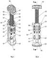
- FIG. 1is a perspective view of a spinal fixation device in accordance with an embodiment of the present disclosure
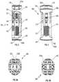
- FIG. 2is a rear view of the spinal fixation device of FIG. 1 ;
- FIG. 3is a side view of the spinal fixation device of FIG. 1 ;
- FIG. 4is a front view of the spinal fixation device of FIG. 1 ;
- FIG. 5Ais a bottom view of the spinal fixation device of FIG. 1 ;
- FIG. 5Bis a top view of the spinal fixation device of FIG. 1 ;
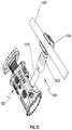
- FIG. 6is a exploded, perspective view of the spinal fixation device of FIG. 1 with parts separated;
- FIG. 7is a perspective view of the spinal fixation device of FIG. 1 with a first end plate spaced apart from a body of the spinal fixation device;
- FIG. 8is a rear view of the spinal fixation device of FIG. 7 ;
- FIG. 9is a cross-sectional view of the spinal fixation device of FIG. 8 cut along section line “ 9 - 9 ” of FIG. 8 ;
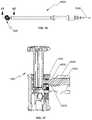
- FIG. 10is a perspective view of an insertion instrument illustrating use with the spinal fixation device of FIG. 1 ;
- FIG. 11is a top view of the insertion instrument of FIG. 10 ;
- FIG. 12is a perspective view of the insertion instrument of FIG. 10 ;
- FIG. 13Ais a side view of a height adjusting driver for use with the insertion instrument of FIG. 10 ;
- FIG. 13Bis a top view of the height adjusting driver of FIG. 13A ;
- FIG. 13Cis a partial side view of a distal portion of the height adjusting driver of FIG. 13A ;
- FIG. 14Ais a side view of an angle adjusting driver for use with the insertion instrument of FIG. 10 ;
- FIG. 14Bis a top view of the angle adjusting driver of FIG. 14A ;
- FIG. 14Cis a partial side view of a distal portion of the angle adjusting driver of FIG. 14A ;
- FIG. 15Ais a side view of a tapered driver for use with the insertion instrument of FIG. 10 ;
- FIG. 15Bis a top view of the tapered driver of FIG. 15A ;
- FIG. 15Cis a partial side view of a distal portion of the tapered driver of FIG. 15A ;
- FIG. 16is a top view of the insertion instrument of FIG. 10 illustrating use with the height adjusting driver of FIG. 13A with the spinal fixation device of FIG. 1 ;
- FIG. 17is a cross-sectional view of the insertion instrument and the spinal fixation device of FIG. 16 cut along section line “ 17 - 17 ” of FIG. 16 ;
- FIG. 18is a top view of the insertion instrument of FIG. 10 illustrating use with the angle adjusting driver of FIG. 14A and the spinal fixation device of FIG. 1 ;
- FIG. 19is a cross-sectional view of the insertion instrument of FIG. 18 cut along section line “ 19 - 19 ” of FIG. 18 ;
- FIG. 20 ais a perspective view of a rod connector for use with the spinal fixation device of FIG. 1 ;
- FIG. 20 bis a perspective view of the rod connector of FIG. 20 a illustrating polyaxial rotation thereof;
- FIG. 21 ais a perspective view of the spinal fixation device of FIG. 1 and the rod connector of FIG. 20 a;
- FIG. 21 bis a perspective view of the spinal fixation device and the rod connector of FIG. 21 a illustrating polyaxial rotation of the rod connector;
- FIG. 22is a perspective view of the spinal fixation device and the rod connector of FIG. 21 a secured with the spinal fixation device illustrating use with a spinal rod;
- FIG. 23is a perspective view of the spinal fixation device of FIG. 22 secured between vertebral bodies by the rod connector and the spinal rod of FIG. 22 ;
- FIG. 24is a perspective view of the spinal fixation device of FIG. 22 secured between the vertebral bodies by a pair of rod connectors and spinal rods of FIG. 22 ;
- FIG. 25is a perspective view of the spinal fixation device of FIG. 1 and a drug delivery assembly operatively coupled with the spinal fixation device;
- FIG. 26is a perspective view of the spinal fixation device of FIG. 23 and a drug delivery assembly in accordance with another embodiment of the present disclosure
- FIG. 27is a perspective view of the spinal fixation device of FIG. 1 and a drug delivery assembly for use with the spinal fixation device in accordance with another embodiment of the present disclosure
- FIG. 28is a perspective view of the spinal fixation device of FIG. 1 and a drug delivery assembly for use with the spinal fixation device in accordance with an alternative embodiment of the present disclosure.
- FIG. 29is a perspective view of the spinal fixation device of FIG. 23 and a shield for use with the spinal fixation device in accordance with an embodiment of the present disclosure, illustrating placement of the shield on the spinal fixation device in phantom.
- proximal and distalmay be employed interchangeably, and should be understood as referring to the portion of a structure that is closer to a clinician during proper use.
- distaland “leading” may also be employed interchangeably, and should be understood as referring to the portion of a structure that is farther from the clinician during proper use.
- cephalador “cranial” is used in this application to indicate a direction toward a patient's head, whereas the term “caudad” indicates a direction toward the patient's feet.
- the term “medial”indicates a direction toward the middle of the body of the patient
- the term “lateral”indicates a direction toward a side of the body of the patient (i.e., away from the middle of the body of the patient).
- the term “posterior”indicates a direction toward the patient's back
- the term “anterior”indicates a direction toward the patient's front.
- spinal fixation device 500configured and adapted to be positioned between vertebral bodies to support vertebral bodies and to promote spinal fusion.
- spinal fixation device 500may be inserted into the patient laterally, posteriorly, anteriorly, or obliquely.
- spinal fixation device 500may be inserted into the patient through procedures such as, e.g., posterior lumbar interbody fusion (PLIF), transforaminal lumbar interbody fusion (TLIF), lateral lumbar interbody fusion (LLIF), oblique lumbar interbody fusion (OLIF), or lateral extracavitary (LECA) procedures.
- PLIFposterior lumbar interbody fusion
- TLIFtransforaminal lumbar interbody fusion
- LLIFlateral lumbar interbody fusion
- OLIFoblique lumbar interbody fusion
- LECAextracavitary
- Spinal fixation device 500includes an outer housing 510 and an end plate assembly 560 interchangeably coupled with outer housing 510 .
- Outer housing 510includes a second end plate 550 .
- End plate assembly 560includes a first end plate 540 , first and second elongate members 666 , 668 operatively supporting first end plate 540 , and a mounting assembly 600 operatively supporting first and second elongate members 666 , 668 .
- First and second end plates 540 , 550are configured to engage end plates of adjacent vertebral bodies.
- first and second end plates 540 , 550are configured to engage, e.g., endplates of superior and inferior vertebral bodies, respectively.
- Each of first and second end plates 540 , 550may include a plurality of pyramidal shaped spikes 533 a , 533 b (i.e., tetrahedrons) to aid in securing spinal fixation device 500 to the adjacent vertebral bodies for enhanced gripping of the vertebral bodies and minimizing movement of spinal fixation device 500 relative to the vertebral bodies.
- each of first and second end plates 540 , 550may include ridges or similar projections to aid in securing spinal fixation device 500 to the vertebral bodies.
- End plate assembly 560is configured as a modular assembly that is interchangeably mounted in outer housing 510 .
- a plurality of end plate assemblies 560may be provided with varying parameters such as, e.g., footprint and lordosis, such that the clinician may selectively attach a desired end plate assembly 560 to outer housing 510 to meet the needs of each patient or surgical procedure being performed.
- end plate assembly 560may be tailored to achieve a desired lordosis of a first end plate 540 and a desired axial spacing between outer housing 510 and first end plate 540 , as will be discussed hereinbelow.
- Spinal fixation device 500may be made of titanium, titanium alloy, stainless steel, allograft bone, autologous bone graft, polyetheretherketone (PEEK), cobalt chrome, polymeric materials, a combination thereof, or any other suitable biocompatible material.
- spinal fixation device 500may be formed of bone, or an artificial material other than bone which may be harder or stronger than bone, such as, e.g., ceramic materials.
- Outer housing 510may include a bone growth promoting material such as, e.g., bone morphogenic protein and hydroxyapatite. Outer housing 510 may define a cavity 551 to accommodate bone graft material therein.
- outer housing 510includes first and second ends 524 , 526 and an outer wall 512 extending between first and second ends 524 , 526 .
- Outer wall 512defines a plurality of bores 521 configured to receive a screw 190 and operatively engage insertion instrument 6000 ( FIG. 10 ), as will be discussed hereinbelow. Bores 521 are circumferentially arranged about outer housing 510 to facilitate insertion of screw 190 and engagement with insertion instrument 6000 at different orientations.
- outer wall 512further defines a plurality of bores 527 ( FIGS.
- outer housing 510to facilitate fixation of spinal stabilization devices such as, e.g., a rod connector 1000 ( FIGS. 20 a and 20 b ), or a drug delivery assembly 1700 ( FIG. 25 ), as will be discussed hereinbelow.
- spinal stabilization devicessuch as, e.g., a rod connector 1000 ( FIGS. 20 a and 20 b ), or a drug delivery assembly 1700 ( FIG. 25 ), as will be discussed hereinbelow.
- the plurality of bores 527may be defined in anterolateral portions of outer housing 510 .
- first end 524 of outer housing 510defines an aperture 522
- second end 526 of outer housing 510includes second end plate 550 , e.g., integrally formed, with outer housing 510 .
- Outer housing 510defines a chamber 520 configured to receive at least a portion of end plate assembly 560 through aperture 522 .
- End plate assembly 560is selectively positionable within chamber 520 .
- End plate assembly 560includes a mounting assembly 600 releasably supported on a shoulder 530 of first end 524 of outer housing 510 .
- Mounting assembly 600includes a retaining housing 602 including first and second housing halves 602 a , 602 b , first and second rotatable members 610 , 612 rotatably supported in retaining housing 602 , and first and second retaining rings 606 , 608 .
- aperture 522 of first end 524 of outer housing 510includes a non-circular cross-section complementary to a transverse cross-section of a first end 615 of retaining housing 602 to inhibit rotation of retaining housing 602 in aperture 522 .
- each of first and second housing halves 602 a , 602 bincludes radially extending first and second protrusions 605 , 607 configured to be received in respective first and second recesses 523 , 525 defined in shoulder 530 of outer housing 510 .
- Outer housing 510defines a pair of bores 571 transverse to a longitudinal axis “A” ( FIG. 9 ) of spinal fixation device 500 .
- Each bore 571is configured to receive a spring pin 577 .
- Each of first and second housing halves 602 a , 602 bdefines a transverse groove 613 on respective second protrusions 607 .
- Transverse groove 613is configured to receive spring pin 577 .
- spring pin 577 inserted through the respective bore 571 of outer housing 510is received through transverse groove 613 of the respective second protrusion 607 to secure retaining housing 602 with outer housing 510 .
- Spring pin 577is flexible to enable the clinician to remove end plate assembly 560 from outer body 510 when end plate assembly 560 is pulled away from outer housing 510 .
- end plate assembly 560When end plate assembly 560 is pulled away from outer housing 510 , spring pin 577 flexes and disengages from transverse groove 613 of second protrusion 607 . In this manner, the clinician is able to interchangeably utilize various end plate assemblies 560 .
- each of first and second housing halves 602 a , 602 bincludes an inner wall 611 defining first and second circumferential grooves 630 , 632 configured to receive at least a portion of first and second retaining rings 606 , 608 , respectively.
- First rotatable member 610defines a circumferential groove 670 configured to support first retaining ring 606 therein.
- First retaining ring 606extends radially outward from circumferential groove 670 of first rotatable member 610 such that at least a portion of first retaining ring 606 is received in first circumferential groove 630 of retaining housing 602 .
- first rotatable member 610is rotatably supported within retaining housing 602 .
- second rotatable member 612defines a circumferential groove 672 configured to support second retaining ring 608 therein.
- Second retaining ring 608extends radially outward from circumferential groove 672 such that at least a portion of second retaining ring 608 is received in second circumferential groove 632 of retaining housing 602 .
- second rotatable member 612is rotatably supported within retaining housing 602 .
- first and second rotatable members 610 , 612are rotatable with respect to retaining housing 602 , while maintaining a fixed axial distance therebetween.
- First and second rotatable members 610 , 612include internal threads 609 , 613 ( FIG. 6 ), respectively.
- internal threads 609 , 613are in opposite orientations, such that when first and second rotatable members 610 , 612 rotate in opposite directions, the orientations of internal threads 609 , 613 are the same.
- Internal threads 609 , 613are configured to threadably engage outer threads 662 , 664 of first and second elongate members 666 , 668 of end plate assembly 560 , respectively.
- first and second rotatable members 610 , 612rotate in opposite directions causes axial movement of first and second elongate members 666 , 668 along longitudinal axis “A-A” ( FIG. 9 ), as will be described hereinbelow.
- first and second rotatable members 610 , 612include opposing teeth 682 , 684 , respectively. Teeth 682 , 684 are configured to engage, e.g., an engaging portion 7030 of a height adjusting driver 7000 ( FIG. 13A ), as will be discussed hereinbelow.
- rotation of height adjusting driver 7000 operatively coupled with teeth 682 , 684causes rotation of first and second rotatable members 610 , 612 , which, in turn, causes axial movement of first and second elongate members 666 , 668 .
- end plate assembly 560is selectively positionable relative to outer housing 510 through rotation of first and second rotatable members 610 , 612 in opposite directions. In this manner, a length of spinal fixation device 500 may be selectively tailored to, e.g., the intervertebral space.
- first end plate 540includes an underside 545 defining first and second grooves 547 , 549 .
- First and second grooves 547 , 549are configured to receive round head portions 666 a , 668 a of first and second elongate members 666 , 668 , respectively.
- Round head portions 666 a , 668 adefine respective bores 666 b , 668 b .
- First end plate 540further defines bores 541 , 543 ( FIG. 7 ) configured to receive respective pins 611 ( FIG. 6 ). In this manner, pins 611 pivotably secure round head portions 666 a , 668 a to first end plate 540 .
- first and second elongate members 666 , 668enables the clinician to adjust angular orientation of first end plate 540 with respect to longitudinal axis “A-A” ( FIG. 9 ) to achieve the desired lordosis, as will be discussed hereinbelow.
- First and second elongate members 666 , 668 of end plate assembly 560include outer threads 662 , 664 configured to engage internal threads 609 , 613 ( FIG. 6 ) of first and second rotatable members 602 , 404 .
- First and second elongate members 666 , 668 of end plate assembly 560are movable relative to each other along longitudinal axis “A-A”.
- first end plate 540may be advantageously angled to provide a desired amount of lordosis tailored to the need of each patient.
- first end plate 540may be positioned substantially orthogonal to the longitudinal axis “A-A” ( FIG. 9 ) and adjacent first end 524 of outer housing 510 .
- first end plate 540may define an acute angle with longitudinal axis “A-A” ( FIG. 9 ) and spaced apart from first end 524 .
- the clinicianmay use angle adjusting driver 8000 to adjust the relative positioning of first and second elongate members 666 , 668 to provide the adequate amount of lordosis of first end plate 540 , as will be described hereinbelow.
- Insertion instrument 6000for use with spinal fixation device 500 to position spinal fixation device 500 between adjacent vertebral bodies.
- Insertion instrument 6000includes a handle 6010 and an elongate body 6020 extending from handle 6010 .
- Insertion instrument 6000defines a channel 6035 ( FIG. 17 ) configured to receive a height adjusting driver 7000 (a distal end of height adjusting driver 700 shown in FIG. 17 ), an angle adjusting driver 8000 ( FIG. 18 ), or a tapered driver 9000 ( FIGS. 15A-C ) therethrough.
- Elongate body 6020includes engaging portion 6032 ( FIG. 17 ) configured to, e.g., threadably, engage bore 521 of outer housing 510 to securely attach spinal fixation device 500 with insertion instrument 6000 .
- Height adjusting driver 7000configured to be received through channel 6035 ( FIG. 17 ) of insertion instrument 6000 .
- Height adjusting driver 7000includes a handle 7010 , an elongate body 7020 , and an engaging portion 7030 .
- Engaging portion 7030includes a plurality of teeth 7032 configured to engage teeth 684 , 682 ( FIG. 6 ) of first and second rotatable members 610 , 612 of mounting assembly 600 , respectively.
- rotation of handle 7010causes concomitant rotation of engaging portion 7030 about elongate body 7020 , which, in turn, causes rotation of first and second rotatable members 610 , 612 in opposite directions.
- Rotation of first and second rotatable members 610 , 612 in opposite directionsimparts axial translation of first and second elongate members 666 , 668 as a single construct, which, in turn, enables the clinician to adjust the axial distance between first end plate 540 and outer housing 510 , i.e., overall height of spinal fixation device 500 .
- Rotation of handle 7010 in an opposite directioncauses axial movement of end plate assembly 560 in an opposite direction.
- Angle adjusting driver 8000configured to be received through channel 6035 ( FIG. 17 ) of insertion instrument 6000 .
- Angle adjusting driver 8000includes a handle 8010 , an elongate body 8020 , and an engaging portion 8030 .
- engaging portion 8030may be radially offset from a central axis “C-C” defined by elongate body 8020 .
- Engaging portion 8030includes a plurality of teeth 8034 configured to engage teeth 682 , 684 ( FIG. 6 ) of either first or second rotatable members 610 , 612 of mounting assembly 600 .
- rotation of handle 8010causes rotation of one of the first or second rotatable members 610 , 612 of mounting assembly 600 .
- Rotation of only one rotatable member 610 , 612causes translation of one of first or second elongate member 666 , 668 .
- Relative movement between first and second elongate members 666 , 668changes angular orientation of first end plate 540 with respect to outer housing 510 and longitudinal axis “A-A.”
- the clinicianmay adjust the angular orientation of first end plate 540 to achieve the desired amount of lordosis or kyphosis.
- height adjusting driver 7000 and angle adjusting driver 8000may be constructed as a single instrument that is configured to be received through channel 6035 ( FIG. 17 ) of insertion instrument 6000 .
- a tapered driver 9000configured to be received through channel 6035 ( FIG. 17 ) of insertion instrument 6000 .
- Tapered driver 9000includes a handle 9010 , an elongate body 9020 , and an engaging portion 9030 .
- screws 190may be positioned in bore 521 of outer housing 510 through channel 6035 of insertion instrument 6000 .
- Teeth 9034 of engaging portion 9030engage teeth on a head portion of screw 190 .
- handle 9010may be rotated to threadably secure screw 190 in bore 521 .
- Rod connector 1000may be used with spinal fixation device 500 to enhance securement of spinal fixation device 500 between vertebral bodies and to promote spinal fusion.
- Rod connector 1000includes an anchoring portion 1010 , a coupling portion 1020 rotatably and pivotably coupled with anchoring portion 1010 , and a head portion 1030 .
- Anchoring portion 1010includes an engaging portion 1012 configured to be threadably coupled with bore 527 ( FIGS. 21 a and 21 b ) of spinal fixation device 500 .
- Anchoring portion 1010further includes a tip portion 1014 extending from engaging portion 1012 .
- Tip portion 1014has a diameter smaller than a diameter of engaging portion 1012 to facilitate alignment of engaging portion 1012 with bore 527 .
- Anchoring portion 1010further includes a ball joint 1016 ( FIG. 20 b ).
- Coupling portion 1020includes a socket 1022 configured to rotatably and pivotably receive ball joint 1016 of anchoring portion 1010 . Under such a configuration, variable or polyaxial adjustments may be made between anchoring portion 1010 and coupling portion 1020 . It is also contemplated that anchoring portion 1010 may include a socket and coupling portion 1020 may include a ball joint.
- Head portion 1030includes a recessed portion 1032 configured to receive spinal rod 1500 therethrough. Head portion 1030 defines slits 1038 configured to flex or enlarge the dimensions of recessed portion 1032 to facilitate insertion of spinal rod 1500 . Head portion 1030 further defines a bore 1034 ( FIG. 21 a ) configured to receive a screw 1040 . Upon insertion of spinal rod 1500 in recessed portion 1032 , screw 1040 may be fastened to secure spinal rod 1500 in recessed portion 1032 . With particular reference to FIG. 22 , spinal rod 1500 may be, e.g., a 5.5 mm diameter round rod. A reference may be made to U.S. patent application Ser. No. 13/251,546, now U.S. Pat. No. 8,920,471, filed on Oct. 3, 2011, entitled “Transverse Connector,” the entire content of which is incorporated herein by reference, for a detailed discussion of the construction and operation of screws.
- spinal fixation device 500may be tailored to a particular surgical procedure being performed.
- spinal fixation device 500 ′may include a plurality of bores 527 ′ axially arranged along a length of spinal fixation device 500 ′.
- rod connector 1000may be secured at a desired location along the length of spinal fixation device 500 to better secure spinal fixation device 500 ′ between vertebral bodies v 1 , v 2 .
- additional rod connectors 1000may be axially placed along the length of spinal fixation device 500 ′ to further secure spinal fixation device 500 ′.
- pedicle screws 1600may be secured to respective vertebral bodies v 1 , v 2 and at least one rod connector 1000 may be secured with spinal fixation device 500 ′.
- Spinal rod 1500may be received through the pedicle screws and rod connector 1000 .
- Screw 1040is utilized to secure spinal rod 1500 in recessed portion 1032 of rod connector 1000 and set screws (not shown) are used to secure spinal rod 1500 with pedicle screws 1600 .
- a referencemay be made to U.S. patent application Ser. No. 12/739,461, now U.S. Pat. No. 8,814,919, filed on Aug.
- a pair of spinal rods 1500may be utilized to further secure spinal fixation device 500 ′ between vertebral bodies v 1 , v 2 .
- additional rod connectors 1000may be axially placed along the length of spinal fixation device 500 ′.
- bores 527may also be used to secure a drug delivery assembly 1700 to deliver a range of different synthetic or naturally occurring pharmaceutical or biological agents in liquid or gel formulations depending upon the particular application.
- Drugsmay be administered for any actual or potential therapeutic, prophylactic or other medicinal purpose.
- Such drugsmay include, e.g., analgesics, anesthetics, antimicrobial agents, antibodies, anticoagulants, antifibrinolytic agents, anti-inflammatory agents, antiparasitic agents, antiviral agents, cytokines, cytotoxins or cell proliferation inhibiting agents, chemotherapeutic agents, radiolabeled compounds or biologics, hormones, interferons, and combinations thereof.
- spinal fixation device 500may be used to deliver a formulation comprising an agent used in chemotherapy or radiotherapy.
- Therapeutic agentsmay include chemotherapeutic agents (for example, paclitaxel, vincristine, ifosfamide, dacttinomycin, doxorubicin, cyclophosphamide, and the like), bisphosphonates (for example, alendronate, pamidronate, clodronate, zoledronic acid, and ibandronic acid), analgesics (such as opioids and NSAIDS), anesthetics (for example, ketoamine, bupivacaine and ropivacaine), tramadol, and dexamethasone.
- drug delivery assembly 1700may be used for delivering an agent useful in radiotherapy in, e.g., beads.
- radioactive agentsthat are capable of targeting a particular tissue, antigen, or receptor type
- the radioactive agentsare administered locally following implantation of spinal fixation device 500 .
- radiotherapy agentsinclude radiolabeled antibodies, radiolabeled peptide receptor ligands, or any other radiolabeled compound capable of specifically binding to the specific targeted cancer cells.
- drug delivery assembly 1700may be used to deliver drugs used in the management of pain and swelling that occurs following the implantation surgery.
- spinal fixation device 500may release an effective amount of an analgesic agent alone or in combination with an anesthetic agent.
- spinal fixation device 500may be used to deliver drugs which help minimize the risk of infection following implantation.
- spinal fixation device 500may release one or more antibiotics (for example, cefazolin, cephalosporin, tobramycin, gentamycin, etc.) and/or another agent effective in preventing or mitigating biofilms (for example, a quorum-sensing blocker or other agent targeting biofilm integrity).
- antibioticsfor example, cefazolin, cephalosporin, tobramycin, gentamycin, etc.
- another agent effective in preventing or mitigating biofilmsfor example, a quorum-sensing blocker or other agent targeting biofilm integrity.
- Biofilmsmay form biofilms on the surface of spinal fixation device 500 , and these biofilms may be relatively impermeable to antibiotics. Accordingly, systemically administered antibiotics may not achieve optimal dosing where it is most needed. However, spinal fixation device 500 enables the delivery of the desired dose of antibiotic precisely when and where needed. In certain circumstances, the antibiotic may be delivered beneath the biofilm.
- drug delivery assembly 1700includes a drug reservoir 1720 secured with bore 527 , a catheter 1730 in fluid communication with drug reservoir 1720 , and a supply port 1740 in fluid communication with catheter 1730 .
- Supply port 1740may be affixed to a location most convenient for the patient or the clinician to supply the drugs using, e.g., syringe 1750 .
- supply port 1740may be affixed to an external location such as, e.g., the skin, of the patient.
- Supply port 1740 shown hereinis merely exemplary and not drawn to scale.
- Supply port 1740 having different sizes, shapes, or profilesmay be utilized for other applications such as, e.g., subcutaneous application.
- the drugs discussed hereinabovemay be supplied through supply port 1740 by a syringe 1750 . It is also contemplated that drug reservoir 1720 may be preloaded with a predetermined amount of drugs to eliminate catheter 1730 , supply port 1740 , and syringe 1750 . It is further contemplated that spinal fixation device 500 may include channels, pores, and/or passages (not shown) formed in, e.g., outer housing 510 . The channels, pores, and/or passages may be in fluid communication with drug reservoir 1720 to facilitate delivery of the drugs from drug reservoir 1720 to the delivery target.
- bores 527 ′ of spinal fixation device 500 ′ or alternatively, bores 527 of spinal fixation device 500may also be used to secure a drug delivery assembly 1800 to deliver the drugs.
- Drug delivery assembly 1800includes a cannula 1810 defining a channel 1820 therethrough. The drugs discussed hereinabove, may be supplied to bores 527 , 527 ′ by syringe 1750 coupled to cannula 1810 . It is contemplated that cannula 1810 may be coupled to spinal fixation device 500 , 500 ′ to supply the drugs to the delivery target during the surgical procedure and may be removed after the completion of the surgical procedure.
- a drug delivery assembly 1900may be utilized to deliver the drugs to the delivery target.
- Drug delivery assembly 1900includes rod connector 2000 , a seal member 2060 , a supply port 1940 , and a catheter 1930 interconnecting supply port 1940 and rod connector 2000 .
- rod connector 2000defines a channel (not shown) extending therethrough such that when rod connector 2000 is coupled with spinal fixation device 500 , 500 ′, the channel is in fluid communication with bore 527 , 527 ′ of spinal fixation device 500 , 500 ′ to facilitate drug delivery through rod connector 2000 .
- Rod connector 2000has a substantially similar configuration as rod connector 1000 .
- Rod connector 2000includes an anchoring portion 2010 , a coupling portion 2020 rotatably and pivotably coupled with anchoring portion 2010 , and a head portion 2030 .
- Anchoring portion 2010includes an engaging portion 2012 configured to be threadably coupled with bore 527 of spinal fixation device 500 .
- Coupling portion 2020is secured with head portion 2030 .
- Head portion 2030includes a recessed portion 2032 configured to receive spinal rod 1500 therethrough. Head portion 2030 defines slits 2038 configured to flex or enlarge the dimensions of recessed portion 2032 to facilitate insertion of spinal rod 1500 .
- Head portion 1030further defines a bore 2034 configured to receive screw 1040 .
- screw 1040may be fastened to secure spinal rod 1500 in recessed portion 2032 .
- head portion 2030defines a bore 2050 in communication with the channel. Bore 2050 is dimensioned to receive seal member 2060 in a sealing relation. Under such a configuration, when the patient or the clinician supplies the drugs through supply port 1940 using, e.g., syringe 1750 ( FIG. 25 ), the drugs flow through the channel of rod connector 2000 and to the drug delivery target through bore 527 , 527 ′ of spinal fixation device 500 , 500 ′.
- rod connector 2000may include a drug reservoir preloaded with a predetermined amount of drugs such that catheter 1930 , supply port 1940 , and seal member 2060 may be eliminated. Under such a configuration, a plug may be used to close bore 2050 in communication with the channel. In this manner, rod connector 2000 may provide, e.g., time-release, drug delivery.
- a drug delivery assembly 3000may be utilized to deliver the drugs to the delivery target.
- drug delivery assembly 3000includes a rod connector 3010 , an engaging portion 3012 , a seal member 3060 , a supply port 3014 , and catheters 3016 a , 3016 b .
- Rod connector 3010is substantially identical to head portion 2030 of drug delivery assembly 1900 , and thus, will not be described in detail herein.
- Rod connector 3010includes a recessed portion 3032 configured to receive spinal rod 1500 therethrough.
- Rod connector 3010defines slits 3038 configured to flex or enlarge the dimensions of recessed portion 3032 to facilitate insertion of spinal rod 1500 .
- Rod connector 3010further defines a bore 3034 configured to receive screw 1040 .
- screw 1040may be fastened to secure spinal rod 1500 in recessed portion 3032 .
- connecting rod 3010defines a bore 3050 .
- Bore 3050is dimensioned to receive seal member 3060 in a sealing relation.
- Catheter 3016 aconnects bore 3050 with engaging portion 3012
- catheter 3016 binterconnects supply port 3014 with seal member 3060 .
- Engaging portion 3012may be e.g., threadably, coupled with bore 527 , 527 ′ of spinal fixation device 500 , 500 ′.
- rod connector 3010may include a drug reservoir preloaded with a predetermined amount of drugs such that catheter 3016 b , supply port 3014 , and seal member 3060 are eliminated. Under such a configuration, a plug (not shown) may be used to close bore 3050 . In this manner, rod connector 3010 may provide, e.g., time-release, drug delivery.
- a shield for use with spinal fixation device 500 , 500 ′is generally shown as 4000 .
- Shield 4000may be affixed to spinal fixation device 500 , 500 ′ using adhesive, ultrasonic welding or other suitable means.
- Shield 4000may include, e.g., polyphenylene sulfide (PPS), to reduce radiation to the spinal cord during, e.g., post-operative radiotherapy.
- PPSpolyphenylene sulfide
- shield 4000may serve as a barrier for bone cement such as, e.g., polymethyl methacrylate (PMMA), drugs, or bone graft products and biologics.
- shield 4000may include, e.g., slow release agents such as antibiotics.
- the clinicianfirst distracts vertebral bodies of interest to establish the intervertebral space.
- the clinicianmay then remove vertebral tissue, if necessary or desired.
- First and second elongate members 666 , 668 of end plate assembly 560are selectively positioned to achieve a desired orientation of first end plate 540 .
- Insertion instrument 6000is coupled with spinal fixation device 500 by, e.g., threadably, coupling engaging portion 6032 ( FIG. 17 ) with bore 521 .
- Spinal fixation device 500is then positioned adjacent a desired intervertebral space between vertebral bodies.
- height adjusting driver 7000can be inserted through channel 6035 ( FIGS.
- insertion instrument 6000to further adjust the axial distance between first end plate 560 and outer housing 510 by placing engaging portion 7030 through one of the plurality of bores 521 defined in outer housing 510 such that teeth 7032 of engaging portion 7030 of height adjusting driver 7000 engages teeth 684 , 682 of first and second rotatable members 610 , 612 of mounting assembly 600 , respectively.
- rotation of handle 7010causes rotation of first and second rotatable members 610 , 612 in opposite directions, which, in turn, imparts axial translation of first and second elongate members 666 , 668 .
- the clinicianmay adjust the axial distance between first end plate 540 and outer housing 510 , i.e., height of spinal fixation device 500 .
- Handle 7010is rotated until a desired height of spinal fixation device 500 is effected through axial movement of end plate assembly 560 .
- angle adjusting driver 8000can be inserted through channel 6035 ( FIG. 19 ) of insertion instrument 6000 to further adjust the angular orientation of first end plate 540 with respect to outer housing 510 .
- Engaging portion 8030is inserted through one of the plurality of bores 521 defined in outer housing 510 such that teeth 8034 of engaging portion 8030 of angle adjusting driver 8000 engages teeth 682 of first rotatable member 610 or teeth 684 of second rotatable member 612 of mounting assembly 600 .
- Rotation of handle 8010causes rotation of one of the first or second rotatable members 610 , 612 of mounting assembly 600 , which, in turn, causes translation of one of first or second elongate members 666 , 668 .
- Relative movement between first and second elongate members 666 , 668enables the clinician to adjust the angular orientation of first end plate 540 with respect to outer housing 510 to achieve the desired lordosis or kyphosis. It is contemplated that the clinician may make further adjustments by alternating height adjusting driver 7000 and angle adjusting driver 8000 to achieve the desired length of spinal fixation device 500 and angular orientation of first end plate 540 .
- screw 190may be placed in bore 521 defined in outer housing 510 through channel 6035 of insertion instrument 6000 .
- Screw 190may be threadably secured in bore 521 by using tapered driver 9000 .
- rod connector 1000pedicle screws 1600 , and spinal rod 1500 may be utilized to further secure spinal fixation device 500 between vertebral bodies and to further promote spinal fusion.
- Anchoring portion 1010 of rod connector 1000is threadably coupled with bore 527 of spinal fixation device 500 , and pedicle screws 1600 are secured with respective vertebral bodies.
- spinal rod 1500is inserted through recessed portion 1032 of rod connector 1000 and respective pedicle screws 1600 .
- rod connector 1000may be adjusted for proper angular orientation.
- Screw 1040may be used to secure spinal rod 1500 in recessed portion 1032 of rod connector 1000 and the set screws (not shown) may be used to secure spinal rod 1500 with pedicle screws 1600 .
- additional rod connector 1000may be used to further secure spinal fixation device 500 between vertebral bodies.
- additional spinal rod 1500may be utilized to further secure spinal fixation device 500 ( FIG. 24 ).
- drug delivery assemblies 1700 , 1800 , 1900 , 3000may be utilized to deliver the necessary drugs to the patient.
- drug reservoir 1720 of drug delivery assembly 1700is secured with bore 527 of spinal fixation device 500 .
- Supply port 1740may be affixed to a location most convenient for the patient or the clinician to supply the drugs using, e.g., syringe 1750 .
- cannula 1810 of drug delivery assembly 1800is secured with bore 527 of spinal fixation device 500 .
- the patient or the clinicianmay administer the drugs using syringe 1750 .
- the use of drug delivery assemblies 1900 , 2000is substantially identical to the use of drug delivery assemblies 1700 , 1800 , and thus, will not be described herein.
- a drug pumpsuch as, e.g., an insulin pump, may be connected to catheter 1730 to supply the drugs.
- first end plate 560may be adjustable in the medial and lateral directions. It is to be understood, therefore, that the disclosure is not limited to those precise embodiments, and that various other changes and modifications may be effected therein by one skilled in the art without departing from the scope or spirit of the disclosure.
Landscapes
- Health & Medical Sciences (AREA)
- Engineering & Computer Science (AREA)
- Biomedical Technology (AREA)
- Orthopedic Medicine & Surgery (AREA)
- Transplantation (AREA)
- Neurology (AREA)
- Oral & Maxillofacial Surgery (AREA)
- Cardiology (AREA)
- Heart & Thoracic Surgery (AREA)
- Vascular Medicine (AREA)
- Life Sciences & Earth Sciences (AREA)
- Animal Behavior & Ethology (AREA)
- General Health & Medical Sciences (AREA)
- Public Health (AREA)
- Veterinary Medicine (AREA)
- Physical Education & Sports Medicine (AREA)
- Surgical Instruments (AREA)
- Prostheses (AREA)
Abstract
Description
Claims (20)
Priority Applications (2)
| Application Number | Priority Date | Filing Date | Title |
|---|---|---|---|
| US16/379,331US11173041B2 (en) | 2013-03-14 | 2019-04-09 | Spinal fixation device |
| US17/505,371US12220325B2 (en) | 2013-03-14 | 2021-10-19 | Spinal fixation device |
Applications Claiming Priority (5)
| Application Number | Priority Date | Filing Date | Title |
|---|---|---|---|
| US201361781837P | 2013-03-14 | 2013-03-14 | |
| US14/212,236US9707096B2 (en) | 2013-03-14 | 2014-03-14 | Spinal fixation device |
| US201462078666P | 2014-11-12 | 2014-11-12 | |
| US14/936,911US10292832B2 (en) | 2013-03-14 | 2015-11-10 | Spinal fixation device |
| US16/379,331US11173041B2 (en) | 2013-03-14 | 2019-04-09 | Spinal fixation device |
Related Parent Applications (1)
| Application Number | Title | Priority Date | Filing Date |
|---|---|---|---|
| US14/936,911DivisionUS10292832B2 (en) | 2013-03-14 | 2015-11-10 | Spinal fixation device |
Related Child Applications (1)
| Application Number | Title | Priority Date | Filing Date |
|---|---|---|---|
| US17/505,371ContinuationUS12220325B2 (en) | 2013-03-14 | 2021-10-19 | Spinal fixation device |
Publications (2)
| Publication Number | Publication Date |
|---|---|
| US20190231557A1 US20190231557A1 (en) | 2019-08-01 |
| US11173041B2true US11173041B2 (en) | 2021-11-16 |
Family
ID=55401196
Family Applications (3)
| Application Number | Title | Priority Date | Filing Date |
|---|---|---|---|
| US14/936,911Active2035-09-06US10292832B2 (en) | 2013-03-14 | 2015-11-10 | Spinal fixation device |
| US16/379,331Active2035-01-02US11173041B2 (en) | 2013-03-14 | 2019-04-09 | Spinal fixation device |
| US17/505,371Active2034-08-11US12220325B2 (en) | 2013-03-14 | 2021-10-19 | Spinal fixation device |
Family Applications Before (1)
| Application Number | Title | Priority Date | Filing Date |
|---|---|---|---|
| US14/936,911Active2035-09-06US10292832B2 (en) | 2013-03-14 | 2015-11-10 | Spinal fixation device |
Family Applications After (1)
| Application Number | Title | Priority Date | Filing Date |
|---|---|---|---|
| US17/505,371Active2034-08-11US12220325B2 (en) | 2013-03-14 | 2021-10-19 | Spinal fixation device |
Country Status (1)
| Country | Link |
|---|---|
| US (3) | US10292832B2 (en) |
Families Citing this family (38)
| Publication number | Priority date | Publication date | Assignee | Title |
|---|---|---|---|---|
| US8597360B2 (en) | 2004-11-03 | 2013-12-03 | Neuropro Technologies, Inc. | Bone fusion device |
| US9358123B2 (en)* | 2011-08-09 | 2016-06-07 | Neuropro Spinal Jaxx, Inc. | Bone fusion device, apparatus and method |
| WO2013023096A1 (en) | 2011-08-09 | 2013-02-14 | Neuropro Technologies, Inc. | Bone fusion device, system and method |
| US9532883B2 (en) | 2012-04-13 | 2017-01-03 | Neuropro Technologies, Inc. | Bone fusion device |
| CA2906531C (en) | 2013-03-15 | 2020-10-06 | Neuropro Technologies, Inc. | Bodiless bone fusion device, apparatus and method |
| FR3010628B1 (en) | 2013-09-18 | 2015-10-16 | Medicrea International | METHOD FOR REALIZING THE IDEAL CURVATURE OF A ROD OF A VERTEBRAL OSTEOSYNTHESIS EQUIPMENT FOR STRENGTHENING THE VERTEBRAL COLUMN OF A PATIENT |
| FR3012030B1 (en) | 2013-10-18 | 2015-12-25 | Medicrea International | METHOD FOR REALIZING THE IDEAL CURVATURE OF A ROD OF A VERTEBRAL OSTEOSYNTHESIS EQUIPMENT FOR STRENGTHENING THE VERTEBRAL COLUMN OF A PATIENT |
| US9974663B2 (en)* | 2014-10-09 | 2018-05-22 | Warsaw Orthopedic, Inc. | Spinal implant system and method |
| US11452612B2 (en)* | 2014-10-09 | 2022-09-27 | Warsaw Orthopedic, Inc. | Spinal implant system and method |
| US10363142B2 (en) | 2014-12-11 | 2019-07-30 | K2M, Inc. | Expandable spinal implants |
| US20160213405A1 (en) | 2015-01-27 | 2016-07-28 | K2M, Inc. | Vertebral plate systems and methods of use |
| US10028841B2 (en) | 2015-01-27 | 2018-07-24 | K2M, Inc. | Interbody spacer |
| US10285825B2 (en)* | 2016-04-07 | 2019-05-14 | Howmedica Osteonics Corp. | Surgical insertion instruments |
| US10420591B2 (en)* | 2016-04-14 | 2019-09-24 | Spinal Simplicity, Llc | Interspinous implant insertion instrument with staggered path implant deployment mechanism |
| WO2018027676A1 (en)* | 2016-08-10 | 2018-02-15 | 北京爱康宜诚医疗器材有限公司 | Artificial vertebral body fixing system |
| WO2018109556A1 (en) | 2016-12-12 | 2018-06-21 | Medicrea International | Systems and methods for patient-specific spinal implants |
| US10973657B2 (en) | 2017-01-18 | 2021-04-13 | Neuropro Technologies, Inc. | Bone fusion surgical system and method |
| US10111760B2 (en) | 2017-01-18 | 2018-10-30 | Neuropro Technologies, Inc. | Bone fusion system, device and method including a measuring mechanism |
| US10729560B2 (en) | 2017-01-18 | 2020-08-04 | Neuropro Technologies, Inc. | Bone fusion system, device and method including an insertion instrument |
| US10213321B2 (en) | 2017-01-18 | 2019-02-26 | Neuropro Technologies, Inc. | Bone fusion system, device and method including delivery apparatus |
| EP3612122B1 (en) | 2017-04-21 | 2023-12-20 | Medicrea International | A system for developing one or more patient-specific spinal implants |
| EP3415108B1 (en) | 2017-05-25 | 2024-09-04 | Stryker European Operations Holdings LLC | Fusion cage with integrated fixation and insertion features |
| US11006981B2 (en) | 2017-07-07 | 2021-05-18 | K2M, Inc. | Surgical implant and methods of additive manufacturing |
| US10441430B2 (en) | 2017-07-24 | 2019-10-15 | K2M, Inc. | Expandable spinal implants |
| WO2019051260A1 (en) | 2017-09-08 | 2019-03-14 | Pioneer Surgical Technology, Inc. | Intervertebral implants, instruments, and methods |
| EP3456297B1 (en) | 2017-09-15 | 2023-10-04 | Howmedica Osteonics Corp. | Instruments for expandable interbody implants |
| US10918422B2 (en) | 2017-12-01 | 2021-02-16 | Medicrea International | Method and apparatus for inhibiting proximal junctional failure |
| US20210077267A1 (en) | 2018-02-26 | 2021-03-18 | K2M, Inc. | Spinal Implants With Custom Density And 3-D Printing Of Spinal Implants |
| USD897527S1 (en)* | 2018-05-04 | 2020-09-29 | Karl Storz Se & Co. Kg | Fixation handle |
| US11944385B2 (en) | 2019-04-02 | 2024-04-02 | Medicrea International | Systems and methods for medical image analysis |
| US11877801B2 (en) | 2019-04-02 | 2024-01-23 | Medicrea International | Systems, methods, and devices for developing patient-specific spinal implants, treatments, operations, and/or procedures |
| US11925417B2 (en) | 2019-04-02 | 2024-03-12 | Medicrea International | Systems, methods, and devices for developing patient-specific spinal implants, treatments, operations, and/or procedures |
| KR102195236B1 (en) | 2019-06-21 | 2020-12-28 | (주)엘앤케이바이오메드 | Anterior To Psoas Fusion Cage for Lumbar Spine Surgery |
| US11534307B2 (en) | 2019-09-16 | 2022-12-27 | K2M, Inc. | 3D printed cervical standalone implant |
| US11769251B2 (en) | 2019-12-26 | 2023-09-26 | Medicrea International | Systems and methods for medical image analysis |
| US12318144B2 (en) | 2021-06-23 | 2025-06-03 | Medicrea International SA | Systems and methods for planning a patient-specific spinal correction |
| CN114699227B (en)* | 2022-06-08 | 2022-08-30 | 北京理贝尔生物工程研究所有限公司 | Vertebral body prosthesis |
| CN115778646B (en)* | 2022-11-16 | 2023-05-16 | 北京纳通医疗科技控股有限公司 | Vertebral body fixation system |
Citations (164)
| Publication number | Priority date | Publication date | Assignee | Title |
|---|---|---|---|---|
| US3374011A (en) | 1966-02-04 | 1968-03-19 | John A. Schipper | Adjustable farm implement tongue |
| US3402947A (en) | 1966-06-20 | 1968-09-24 | John A Donato | Connector |
| US3588023A (en) | 1968-09-16 | 1971-06-28 | Maurice Cohen | Vertically adjustable standard |
| US3893730A (en) | 1974-08-05 | 1975-07-08 | Lear Siegler Inc | Seat positioner |
| US4387926A (en) | 1981-06-26 | 1983-06-14 | Rockwell International Corporation | Seat positioner |
| US4554914A (en) | 1983-10-04 | 1985-11-26 | Kapp John P | Prosthetic vertebral body |
| SU1560184A1 (en) | 1988-07-29 | 1990-04-30 | Харьковский Научно-Исследовательский Институт Ортопедии И Травматологии Им.Проф.М.И.Ситенко | Endoprosthesis of spinal column segments |
| US4938319A (en) | 1987-11-14 | 1990-07-03 | Ernst Hans Hellmut | Linearly adjustable force transfer element with stepless inertia-sensitive blocking |
| US5053036A (en) | 1987-11-03 | 1991-10-01 | Synthes (U.S.A.) | Point contact bone compression plate |
| US5108066A (en) | 1990-04-13 | 1992-04-28 | Lundstrom Donald A | Hand releasable locking collar |
| US5236460A (en) | 1990-02-12 | 1993-08-17 | Midas Rex Pneumatic Tools, Inc. | Vertebral body prosthesis |
| US5290312A (en) | 1991-09-03 | 1994-03-01 | Alphatec | Artificial vertebral body |
| US5336223A (en) | 1993-02-04 | 1994-08-09 | Rogers Charles L | Telescoping spinal fixator |
| US5360430A (en) | 1993-07-29 | 1994-11-01 | Lin Chih I | Intervertebral locking device |
| US5458641A (en) | 1993-09-08 | 1995-10-17 | Ramirez Jimenez; Juan J. | Vertebral body prosthesis |
| US5520690A (en) | 1995-04-13 | 1996-05-28 | Errico; Joseph P. | Anterior spinal polyaxial locking screw plate assembly |
| US5547308A (en) | 1992-04-28 | 1996-08-20 | Dzus Fastener Europe Limited | Fastening device |
| US5571190A (en) | 1993-08-20 | 1996-11-05 | Heinrich Ulrich | Implant for the replacement of vertebrae and/or stabilization and fixing of the spinal column |
| US5571192A (en) | 1994-07-02 | 1996-11-05 | Heinrich Ulrich | Prosthetic vertebral implant |
| US5702455A (en) | 1996-07-03 | 1997-12-30 | Saggar; Rahul | Expandable prosthesis for spinal fusion |
| US5723013A (en) | 1995-02-06 | 1998-03-03 | Jbs S.A. | Spacer implant for substituting missing vertebrae |
| US5738685A (en) | 1993-05-18 | 1998-04-14 | Schafer Micomed Gmbh | Osteosynthesis device |
| US5776198A (en) | 1994-12-09 | 1998-07-07 | Sdgi Holdings, Inc. | Adjustable vertebral body replacement |
| WO1998046173A1 (en) | 1997-04-15 | 1998-10-22 | Synthes Ag Chur | Telescopic vertebral prosthesis |
| US5885286A (en) | 1996-09-24 | 1999-03-23 | Sdgi Holdings, Inc. | Multi-axial bone screw assembly |
| US5888014A (en) | 1997-04-14 | 1999-03-30 | Lung; Jimmy R. | Extensible lockable apparatus |
| US5901798A (en) | 1993-10-14 | 1999-05-11 | Hydril U.K. Limited | Drill pipe tubing and casing protectors |
| US5904683A (en) | 1998-07-10 | 1999-05-18 | Sulzer Spine-Tech Inc. | Anterior cervical vertebral stabilizing device |
| DE19804765A1 (en) | 1998-02-06 | 1999-08-26 | Biedermann Motech Gmbh | Placeholder with adjustable axial length |
| US5980522A (en) | 1994-07-22 | 1999-11-09 | Koros; Tibor | Expandable spinal implants |
| US5989290A (en) | 1995-05-24 | 1999-11-23 | Biedermann; Lutz | Height-adjustable artificial vertebral body |
| US6074391A (en) | 1997-06-16 | 2000-06-13 | Howmedica Gmbh | Receiving part for a retaining component of a vertebral column implant |
| US6099531A (en) | 1998-08-20 | 2000-08-08 | Bonutti; Peter M. | Changing relationship between bones |
| US6110172A (en) | 1998-07-31 | 2000-08-29 | Jackson; Roger P. | Closure system for open ended osteosynthesis apparatus |
| US6132434A (en) | 1996-11-07 | 2000-10-17 | Sdgi Holdings, Inc. | Multi-angle bone screw assembly using shape-memory technology |
| US6179514B1 (en) | 1999-05-28 | 2001-01-30 | Kun-Chia Cheng | Telescopic tube joint |
| US6183517B1 (en) | 1998-12-16 | 2001-02-06 | Loubert Suddaby | Expandable intervertebral fusion implant and applicator |
| US6193756B1 (en) | 1997-09-30 | 2001-02-27 | Sulzer Orthopaedie Ag | Tubular support body for bridging two vertebrae |
| US6193755B1 (en) | 1996-09-26 | 2001-02-27 | Howmedica Gmbh | Spinal cage assembly |
| US6235062B1 (en) | 1994-09-06 | 2001-05-22 | Finn Gramnas | Fastening device for prosthesis |
| US6241769B1 (en) | 1998-05-06 | 2001-06-05 | Cortek, Inc. | Implant for spinal fusion |
| US6254602B1 (en) | 1999-05-28 | 2001-07-03 | Sdgi Holdings, Inc. | Advanced coupling device using shape-memory technology |
| US6273888B1 (en) | 1999-05-28 | 2001-08-14 | Sdgi Holdings, Inc. | Device and method for selectively preventing the locking of a shape-memory alloy coupling system |
| US20010021851A1 (en) | 1998-07-20 | 2001-09-13 | Roland Eberlein | Fastening assembly |
| US6296665B1 (en) | 2000-03-20 | 2001-10-02 | Electro-Biology, Inc. | Method and apparatus for spinal fixation |
| US6296642B1 (en) | 1998-11-09 | 2001-10-02 | Sdgi Holdings, Inc. | Reverse angle thread for preventing splaying in medical devices |
| US6302888B1 (en) | 1999-03-19 | 2001-10-16 | Interpore Cross International | Locking dovetail and self-limiting set screw assembly for a spinal stabilization member |
| US6332895B1 (en) | 2000-03-08 | 2001-12-25 | Loubert Suddaby | Expandable intervertebral fusion implant having improved stability |
| US6342074B1 (en) | 1999-04-30 | 2002-01-29 | Nathan S. Simpson | Anterior lumbar interbody fusion implant and method for fusing adjacent vertebrae |
| US6364880B1 (en) | 1994-03-28 | 2002-04-02 | Gary Karlin Michelson | Spinal implant with bone screws |
| US6375683B1 (en) | 1997-05-02 | 2002-04-23 | Stryker France S.A. | Implant in particular for replacing a vertebral body in surgery of the spine |
| US6395034B1 (en) | 1999-11-24 | 2002-05-28 | Loubert Suddaby | Intervertebral disc prosthesis |
| US6419705B1 (en) | 1999-06-23 | 2002-07-16 | Sulzer Spine-Tech Inc. | Expandable fusion device and method |
| US6440170B1 (en) | 2000-12-04 | 2002-08-27 | Roger P. Jackson | Threaded interbody device |
| US20020128654A1 (en) | 1998-02-18 | 2002-09-12 | Steger Shon D. | Method and apparatus for bone fracture fixation |
| US20020161441A1 (en) | 1998-10-15 | 2002-10-31 | Bruno Lang | Telescopic vertebral prosthesis |
| US6500178B2 (en) | 1997-01-02 | 2002-12-31 | St. Francis Medical Technologies, Inc. | Spine distraction implant and method |
| WO2003032812A2 (en) | 2001-10-17 | 2003-04-24 | Medicinelodge, Inc. | Adjustable bone fusion implant and method |
| US6558423B1 (en) | 1999-05-05 | 2003-05-06 | Gary K. Michelson | Interbody spinal fusion implants with multi-lock for locking opposed screws |
| US20030130737A1 (en) | 2000-02-22 | 2003-07-10 | Mcgahan Thomas V. | Anterior impacted bone graft and driver instruments |
| US6610090B1 (en) | 1998-01-30 | 2003-08-26 | Königsee Implantate und Instrumente zur Ostheosynthese GmbH | Height-adjustable vertebral implant |
| US6616695B1 (en) | 1998-01-30 | 2003-09-09 | Stryker Spine | Implant for replacing a vertebra |
| US20030181980A1 (en) | 2002-03-21 | 2003-09-25 | Berry Bret M. | Vertebral body and disc space replacement devices |
| US6629998B1 (en) | 2000-08-23 | 2003-10-07 | Chih-I Lin | Intervertebral retrieval device |
| US6660038B2 (en) | 2000-03-22 | 2003-12-09 | Synthes (Usa) | Skeletal reconstruction cages |
| US6663060B1 (en) | 2002-09-26 | 2003-12-16 | Robert Wayne Gifford, Sr. | Microphone stand |
| US6716214B1 (en) | 2003-06-18 | 2004-04-06 | Roger P. Jackson | Polyaxial bone screw with spline capture connection |
| US6730088B2 (en) | 2001-08-29 | 2004-05-04 | Chung-Chun Yeh | Device for fixing spinal column under treatment |
| US6752832B2 (en) | 2000-12-27 | 2004-06-22 | Ulrich Gmbh & Co., Kg | Vertebral implant and setting tool therefor |
| US6770096B2 (en) | 1999-07-01 | 2004-08-03 | Spinevision S.A. | Interbody spinal stabilization cage and spinal stabilization method |
| US20040186569A1 (en) | 2003-03-20 | 2004-09-23 | Berry Bret M. | Height adjustable vertebral body and disc space replacement devices |
| US6827719B2 (en) | 2001-02-15 | 2004-12-07 | K2 Medical, Llc | Polyaxial pedicle screw having a rotating locking element |
| US20040247379A1 (en) | 2001-07-24 | 2004-12-09 | Pascal Guidetti | Device for locking two telescopic elongated elements |
| US6834840B1 (en) | 2000-08-01 | 2004-12-28 | Hill-Rom Services, Inc. | Medical device support assembly |
| US6835196B2 (en) | 2001-03-27 | 2004-12-28 | Biedermann Motech Gmbh | Anchoring element |
| US6837889B2 (en) | 2002-03-01 | 2005-01-04 | Endius Incorporated | Apparatus for connecting a longitudinal member to a bone portion |
| US6843791B2 (en) | 2003-01-10 | 2005-01-18 | Depuy Acromed, Inc. | Locking cap assembly for spinal fixation instrumentation |
| US6866682B1 (en) | 1999-09-02 | 2005-03-15 | Stryker Spine | Distractable corpectomy device |
| US20050060034A1 (en) | 2003-09-15 | 2005-03-17 | Sdgi Holdings, Inc. | Revisable prosthetic device |
| US6869112B2 (en) | 2000-04-17 | 2005-03-22 | Pascal Guidetti | Device for locking two telescopic elongated elements |
| US6869433B2 (en) | 2001-01-12 | 2005-03-22 | Depuy Acromed, Inc. | Polyaxial screw with improved locking |
| US20050085910A1 (en) | 2003-10-16 | 2005-04-21 | Sweeney Patrick J. | Vertebral prosthesis |
| US6884244B1 (en) | 2000-06-06 | 2005-04-26 | Roger P. Jackson | Removable medical implant closure for open headed implants |
| US6893443B2 (en) | 1999-07-07 | 2005-05-17 | Synthes (U.S.A) | Angle-adjustable bone screw and fixation device |
| US6896677B1 (en) | 2003-12-11 | 2005-05-24 | A-Spine Holding Group Corp. | Rotary device for retrieving spinal column under treatment |
| US6918911B2 (en) | 2002-03-27 | 2005-07-19 | Biedermann Motech Gmbh | Bone anchoring device for stabilizing bone segments and seat part of a bone anchoring device |
| US6945975B2 (en) | 2003-07-07 | 2005-09-20 | Aesculap, Inc. | Bone fixation assembly and method of securement |
| US20050209697A1 (en) | 2000-12-05 | 2005-09-22 | Stryker Spine | Spinal intervertebral implant adjustable in situ comprising hard pass point |
| US20050218275A1 (en) | 2004-04-06 | 2005-10-06 | Allan Keating | Stand |
| US6972019B2 (en) | 2001-01-23 | 2005-12-06 | Michelson Gary K | Interbody spinal implant with trailing end adapted to receive bone screws |
| US20050273173A1 (en) | 2003-08-05 | 2005-12-08 | Gordon Charles R | Expandable articulating intervertebral implant with cam |
| US6984234B2 (en) | 2003-04-21 | 2006-01-10 | Rsb Spine Llc | Bone plate stabilization system and method for its use |
| US20060041260A1 (en) | 2000-02-01 | 2006-02-23 | Orbay Jorge L | Fixation system with plate having holes with divergent axes and multidirectional fixators for use therethrough |
| US20060074490A1 (en) | 2004-10-01 | 2006-04-06 | Sweeney Patrick J | Vertebral prosthesis and spinal fixation system |
| US7025787B2 (en) | 2001-11-26 | 2006-04-11 | Sdgi Holdings, Inc. | Implantable joint prosthesis and associated instrumentation |
| US20060100710A1 (en) | 2003-04-28 | 2006-05-11 | Michael Gutlin | Intervertebral implant |
| US7056343B2 (en) | 2002-03-02 | 2006-06-06 | Bernd Schafer | Extendable spinal implant and extension tool |
| US20060122701A1 (en) | 2004-11-23 | 2006-06-08 | Kiester P D | Posterior lumbar interbody fusion expandable cage with lordosis and method of deploying the same |
| US20060129244A1 (en) | 2004-10-25 | 2006-06-15 | Alphaspine, Inc. | Expandable intervertebral spacer method and apparatus |
| US20060149251A1 (en) | 2004-12-22 | 2006-07-06 | Tara Ziolo | Bone fixation system |
| US20060149385A1 (en) | 2002-09-23 | 2006-07-06 | Mckay William F | Expandable spinal fusion device and methods of promoting spinal fusion |
| US7077864B2 (en) | 2002-02-12 | 2006-07-18 | Cross Medical Products, Inc. | Vertebral interbody cage with translatable locking screw |
| US20060173456A1 (en) | 2005-01-31 | 2006-08-03 | Hawkes David T | Polyaxial pedicle screw assembly |
| US7087057B2 (en) | 2003-06-27 | 2006-08-08 | Depuy Acromed, Inc. | Polyaxial bone screw |
| US7086631B2 (en) | 2004-03-03 | 2006-08-08 | Eml Technologies Llc | Quick-release telescoping tripod |
| US7094257B2 (en) | 2003-02-14 | 2006-08-22 | Zimmer Spine, Inc. | Expandable intervertebral implant cage |
| US20060200244A1 (en) | 2003-02-05 | 2006-09-07 | Richard Assaker | Vertebral replacement and distraction device for placing said implant |
| US20060212118A1 (en) | 2005-03-16 | 2006-09-21 | Abernathie Dennis L | Spinal fusion cage and method of use |
| US20060217715A1 (en) | 2005-03-24 | 2006-09-28 | Depuy Spine, Inc. | Low profile spinal tethering systems |
| US20060241762A1 (en) | 2003-12-11 | 2006-10-26 | Deltacor Gmbh | Height-adjustable spinal implant and operating instrument for the implant |
| US20060241770A1 (en) | 2005-04-21 | 2006-10-26 | Rhoda William S | Expandable vertebral prosthesis |
| US20060271047A1 (en) | 2005-05-10 | 2006-11-30 | Jackson Roger P | Polyaxial bone screw with compound articulation |
| US20060276792A1 (en) | 2005-05-25 | 2006-12-07 | Ensign Michael D | Low profile pedicle screw and rod assembly |
| US20070010887A1 (en) | 2002-03-30 | 2007-01-11 | Williams Lytton A | Intervertebral Device and Method of Use |
| US20070032871A1 (en) | 2000-02-04 | 2007-02-08 | Michelson Gary K | Expandable push-in arcuate orthopedic implant |
| US7175624B2 (en) | 2002-12-31 | 2007-02-13 | Depuy Spine, Inc. | Bone plate and screw system allowing bi-directional assembly |
| US20070073298A1 (en) | 2003-12-22 | 2007-03-29 | Florian Beutter | Bone plate |
| US20070093817A1 (en) | 2005-09-29 | 2007-04-26 | Michael Barrus | Spinal fixation system having locking and unlocking devices for use with a multi-planar, taper lock screw |
| US20070100340A1 (en) | 2005-10-27 | 2007-05-03 | Sdgi Holdings, Inc. | Intervertebral prosthetic device for spinal stabilization and method of implanting same |
| US20070106231A1 (en) | 2003-11-25 | 2007-05-10 | Snow Jeremy K | Resettable safety shield for medical needles |
| US20070162126A1 (en) | 2005-12-01 | 2007-07-12 | Sdgi Holdings, Inc. | End device for a vertebral implant |
| US20070191954A1 (en) | 2005-04-21 | 2007-08-16 | Noah Hansell | Expandable Vertebral Prosthesis |
| US20070219635A1 (en) | 2002-02-19 | 2007-09-20 | Claude Mathieu | Intervertebral implant |
| US7285134B2 (en) | 2003-10-22 | 2007-10-23 | Warsaw Orthopedic, Inc. | Vertebral body replacement implant |
| US20070250171A1 (en) | 2006-04-24 | 2007-10-25 | Sdgi Holdings, Inc. | Expandable intervertebral devices and methods of use |
| US20070255408A1 (en) | 2006-04-27 | 2007-11-01 | Sdgi Holdings, Inc. | Stabilized, adjustable expandable implant and method |
| US20070270964A1 (en) | 2006-04-27 | 2007-11-22 | Sdgi Holdings, Inc. | Expandable vertebral implant and methods of use |
| US20070270968A1 (en) | 2004-02-10 | 2007-11-22 | Baynham Bret O | Plif opposing wedge ramp |
| US20070282441A1 (en) | 2006-05-19 | 2007-12-06 | Katie Stream | Spinal Stabilization Device and Methods |
| FR2902315A1 (en) | 2006-06-20 | 2007-12-21 | Abbott Spine Sa | INTERVERTEBRAL DISTRACTABLE IMPLANT |
| WO2008005627A2 (en) | 2006-07-06 | 2008-01-10 | Lanx, Llc | Expandable spinal fusion cage |
| US7318825B2 (en) | 2003-12-22 | 2008-01-15 | Life Spine Llc | Dynamic cervical plates and cervical plate constructs |
| EP1878408A1 (en) | 2006-07-14 | 2008-01-16 | BIEDERMANN MOTECH GmbH | A spacer for insertion between two vertebrae |
| US20080021555A1 (en) | 2006-07-19 | 2008-01-24 | John White | Expandable vertebral body implants and methods of use |
| US20080114467A1 (en) | 2006-11-09 | 2008-05-15 | Warsaw Orthopedic, Inc. | Expanding Vertebral Body Implant |
| US20080125864A1 (en) | 2006-04-12 | 2008-05-29 | Spinalmotion, Inc. | Posterior Spinal Device and Method |
| US20080147193A1 (en) | 2006-11-23 | 2008-06-19 | Wilfried Matthis | Expandable intervertebral implant |
| US20080167720A1 (en) | 2007-01-08 | 2008-07-10 | Warsaw Orthopedic, Inc. | Expandable vertebral body replacement device |
| US20080249624A1 (en) | 2003-12-12 | 2008-10-09 | Co.Don Ag | Method for the Production of Intervertebral Disk Cell Transplants and Their Use as Transplantation Material |
| US20080249625A1 (en) | 2007-04-03 | 2008-10-09 | Warsaw Orthopedic, Inc. | Composite Interbody Spacer |
| US20080288071A1 (en) | 2006-05-16 | 2008-11-20 | Ashok Biyani | Expandable corpectomy device |
| WO2009023016A1 (en) | 2007-08-15 | 2009-02-19 | Warsaw Orthopedic, Inc. | Expandable vertebral implant and methods of use |
| US7531002B2 (en) | 2004-04-16 | 2009-05-12 | Depuy Spine, Inc. | Intervertebral disc with monitoring and adjusting capabilities |
| US7544208B1 (en) | 2004-05-03 | 2009-06-09 | Theken Spine, Llc | Adjustable corpectomy apparatus |
| US7611104B1 (en) | 2007-01-29 | 2009-11-03 | Gifford Sr Robert Wayne | Stand for supporting an object |
| US20100005715A1 (en) | 2006-12-07 | 2010-01-14 | Allsop, Inc. | Adjustable garden stake |
| US7651517B2 (en) | 2002-12-31 | 2010-01-26 | Depuy Acromed, Inc. | Bone plate and resilient screw system allowing bi-directional assembly |
| US7691147B2 (en) | 2002-12-06 | 2010-04-06 | Synthes Usa, Llc | Intervertebral implant |
| US20100137919A1 (en) | 2006-12-20 | 2010-06-03 | Dietmar Wolter | Bone screw |
| US20100318092A1 (en) | 2009-06-10 | 2010-12-16 | Butler Michael S | Instruments For Installing Multi-Section Intervertebral Spinal Implants |
| US7862616B2 (en) | 2003-02-06 | 2011-01-04 | Synthes Usa, Llc | Intervertebral implant |
| US20110160861A1 (en) | 2009-07-22 | 2011-06-30 | Jimenez Omar F | Methods and apparatuses for vertebral body distraction and fusion employing a coaxial screw gear sleeve mechanism |
| US20110208248A1 (en) | 2007-10-23 | 2011-08-25 | Michael Barrus | Polyaxial screw assembly |
| US8137405B2 (en) | 2008-10-08 | 2012-03-20 | K2M, Inc. | Spinal interbody spacer |
| US20120179255A1 (en)* | 2011-01-12 | 2012-07-12 | Ebi, Llc | Expandable spinal implant device |
| US8353961B2 (en) | 2008-02-07 | 2013-01-15 | K2M, Inc. | Expandable vertebral device with cam lock |
| US8377101B2 (en) | 2008-11-05 | 2013-02-19 | K2M, Inc. | Multi-planar taper lock screw with increased rod friction |
| US8585761B2 (en) | 2008-03-28 | 2013-11-19 | K2M, Inc. | Expandable cage with locking device |
| US8673011B2 (en) | 2008-03-28 | 2014-03-18 | K2M, Inc. | Expandable cage |
| US20140135931A1 (en) | 2012-11-15 | 2014-05-15 | DePuy Synthes Products, LLC | Endplate for a vertebral implant |
| US8801791B2 (en) | 2006-09-27 | 2014-08-12 | K2M, Inc. | Spinal interbody spacer |
| US8814919B2 (en) | 2007-10-23 | 2014-08-26 | K2M, Inc. | Posterior pedicle screw having a taper lock |
| US20140277503A1 (en) | 2013-03-14 | 2014-09-18 | K2M, Inc. | Spinal fixation device |
| US8920471B2 (en) | 2010-07-12 | 2014-12-30 | K2M, Inc. | Transverse connector |
Family Cites Families (1)
| Publication number | Priority date | Publication date | Assignee | Title |
|---|---|---|---|---|
| US8202321B2 (en)* | 2009-06-17 | 2012-06-19 | Ulrich Gmbh & Co. Kg | Implant |
- 2015
- 2015-11-10USUS14/936,911patent/US10292832B2/enactiveActive
- 2019
- 2019-04-09USUS16/379,331patent/US11173041B2/enactiveActive
- 2021
- 2021-10-19USUS17/505,371patent/US12220325B2/enactiveActive
Patent Citations (188)
| Publication number | Priority date | Publication date | Assignee | Title |
|---|---|---|---|---|
| US3374011A (en) | 1966-02-04 | 1968-03-19 | John A. Schipper | Adjustable farm implement tongue |
| US3402947A (en) | 1966-06-20 | 1968-09-24 | John A Donato | Connector |
| US3588023A (en) | 1968-09-16 | 1971-06-28 | Maurice Cohen | Vertically adjustable standard |
| US3893730A (en) | 1974-08-05 | 1975-07-08 | Lear Siegler Inc | Seat positioner |
| US4387926A (en) | 1981-06-26 | 1983-06-14 | Rockwell International Corporation | Seat positioner |
| US4554914A (en) | 1983-10-04 | 1985-11-26 | Kapp John P | Prosthetic vertebral body |
| US5053036A (en) | 1987-11-03 | 1991-10-01 | Synthes (U.S.A.) | Point contact bone compression plate |
| US4938319A (en) | 1987-11-14 | 1990-07-03 | Ernst Hans Hellmut | Linearly adjustable force transfer element with stepless inertia-sensitive blocking |
| SU1560184A1 (en) | 1988-07-29 | 1990-04-30 | Харьковский Научно-Исследовательский Институт Ортопедии И Травматологии Им.Проф.М.И.Ситенко | Endoprosthesis of spinal column segments |
| US5236460A (en) | 1990-02-12 | 1993-08-17 | Midas Rex Pneumatic Tools, Inc. | Vertebral body prosthesis |
| US5108066A (en) | 1990-04-13 | 1992-04-28 | Lundstrom Donald A | Hand releasable locking collar |
| US5290312A (en) | 1991-09-03 | 1994-03-01 | Alphatec | Artificial vertebral body |
| US5547308A (en) | 1992-04-28 | 1996-08-20 | Dzus Fastener Europe Limited | Fastening device |
| US5336223A (en) | 1993-02-04 | 1994-08-09 | Rogers Charles L | Telescoping spinal fixator |
| US5738685A (en) | 1993-05-18 | 1998-04-14 | Schafer Micomed Gmbh | Osteosynthesis device |
| US5360430A (en) | 1993-07-29 | 1994-11-01 | Lin Chih I | Intervertebral locking device |
| US5571190A (en) | 1993-08-20 | 1996-11-05 | Heinrich Ulrich | Implant for the replacement of vertebrae and/or stabilization and fixing of the spinal column |
| US5458641A (en) | 1993-09-08 | 1995-10-17 | Ramirez Jimenez; Juan J. | Vertebral body prosthesis |
| US5901798A (en) | 1993-10-14 | 1999-05-11 | Hydril U.K. Limited | Drill pipe tubing and casing protectors |
| US6364880B1 (en) | 1994-03-28 | 2002-04-02 | Gary Karlin Michelson | Spinal implant with bone screws |
| US5571192A (en) | 1994-07-02 | 1996-11-05 | Heinrich Ulrich | Prosthetic vertebral implant |
| US5980522A (en) | 1994-07-22 | 1999-11-09 | Koros; Tibor | Expandable spinal implants |
| US6235062B1 (en) | 1994-09-06 | 2001-05-22 | Finn Gramnas | Fastening device for prosthesis |
| US5776198A (en) | 1994-12-09 | 1998-07-07 | Sdgi Holdings, Inc. | Adjustable vertebral body replacement |
| US5723013A (en) | 1995-02-06 | 1998-03-03 | Jbs S.A. | Spacer implant for substituting missing vertebrae |
| US5520690A (en) | 1995-04-13 | 1996-05-28 | Errico; Joseph P. | Anterior spinal polyaxial locking screw plate assembly |
| US5989290A (en) | 1995-05-24 | 1999-11-23 | Biedermann; Lutz | Height-adjustable artificial vertebral body |
| US5702455A (en) | 1996-07-03 | 1997-12-30 | Saggar; Rahul | Expandable prosthesis for spinal fusion |
| US5885286A (en) | 1996-09-24 | 1999-03-23 | Sdgi Holdings, Inc. | Multi-axial bone screw assembly |
| US6193755B1 (en) | 1996-09-26 | 2001-02-27 | Howmedica Gmbh | Spinal cage assembly |
| US6132434A (en) | 1996-11-07 | 2000-10-17 | Sdgi Holdings, Inc. | Multi-angle bone screw assembly using shape-memory technology |
| US20020032443A1 (en) | 1996-11-07 | 2002-03-14 | Sherman Michael C. | Multi-angle bone screw assembly using shape-memory technology |
| US6500178B2 (en) | 1997-01-02 | 2002-12-31 | St. Francis Medical Technologies, Inc. | Spine distraction implant and method |
| US5888014A (en) | 1997-04-14 | 1999-03-30 | Lung; Jimmy R. | Extensible lockable apparatus |
| US6176881B1 (en) | 1997-04-15 | 2001-01-23 | Synthes | Telescopic vertebral prosthesis |
| WO1998046173A1 (en) | 1997-04-15 | 1998-10-22 | Synthes Ag Chur | Telescopic vertebral prosthesis |
| US6375683B1 (en) | 1997-05-02 | 2002-04-23 | Stryker France S.A. | Implant in particular for replacing a vertebral body in surgery of the spine |
| US6074391A (en) | 1997-06-16 | 2000-06-13 | Howmedica Gmbh | Receiving part for a retaining component of a vertebral column implant |
| US6193756B1 (en) | 1997-09-30 | 2001-02-27 | Sulzer Orthopaedie Ag | Tubular support body for bridging two vertebrae |
| US6616695B1 (en) | 1998-01-30 | 2003-09-09 | Stryker Spine | Implant for replacing a vertebra |
| US6908485B2 (en) | 1998-01-30 | 2005-06-21 | Stryker Spine | Implant for replacing a vertebra |
| US6610090B1 (en) | 1998-01-30 | 2003-08-26 | Königsee Implantate und Instrumente zur Ostheosynthese GmbH | Height-adjustable vertebral implant |
| US6200348B1 (en) | 1998-02-06 | 2001-03-13 | Biedermann, Motech Gmbh | Spacer with adjustable axial length |
| DE19804765A1 (en) | 1998-02-06 | 1999-08-26 | Biedermann Motech Gmbh | Placeholder with adjustable axial length |
| US20020128654A1 (en) | 1998-02-18 | 2002-09-12 | Steger Shon D. | Method and apparatus for bone fracture fixation |
| US7052499B2 (en) | 1998-02-18 | 2006-05-30 | Walter Lorenz Surgical, Inc. | Method and apparatus for bone fracture fixation |
| US6241769B1 (en) | 1998-05-06 | 2001-06-05 | Cortek, Inc. | Implant for spinal fusion |
| US5904683A (en) | 1998-07-10 | 1999-05-18 | Sulzer Spine-Tech Inc. | Anterior cervical vertebral stabilizing device |
| US7229443B2 (en) | 1998-07-20 | 2007-06-12 | Biedermann Motech Gmbh | Fastening assembly with improved handling properties |
| US20010021851A1 (en) | 1998-07-20 | 2001-09-13 | Roland Eberlein | Fastening assembly |
| US6110172A (en) | 1998-07-31 | 2000-08-29 | Jackson; Roger P. | Closure system for open ended osteosynthesis apparatus |
| US6423063B1 (en) | 1998-08-20 | 2002-07-23 | Peter M. Bonutti | Changing relationship between bones |
| US7001385B2 (en) | 1998-08-20 | 2006-02-21 | Bonutti Ip, Llc | Joint spacer with compartment for orthobiologic material |
| US6099531A (en) | 1998-08-20 | 2000-08-08 | Bonutti; Peter M. | Changing relationship between bones |
| US6524341B2 (en) | 1998-10-15 | 2003-02-25 | Synthes (Usa) | Telescopic vertebral prosthesis |
| US20020161441A1 (en) | 1998-10-15 | 2002-10-31 | Bruno Lang | Telescopic vertebral prosthesis |
| US6296642B1 (en) | 1998-11-09 | 2001-10-02 | Sdgi Holdings, Inc. | Reverse angle thread for preventing splaying in medical devices |
| US6183517B1 (en) | 1998-12-16 | 2001-02-06 | Loubert Suddaby | Expandable intervertebral fusion implant and applicator |
| US6302888B1 (en) | 1999-03-19 | 2001-10-16 | Interpore Cross International | Locking dovetail and self-limiting set screw assembly for a spinal stabilization member |
| US6342074B1 (en) | 1999-04-30 | 2002-01-29 | Nathan S. Simpson | Anterior lumbar interbody fusion implant and method for fusing adjacent vertebrae |
| US7033394B2 (en) | 1999-05-05 | 2006-04-25 | Sdgi Holdings, Inc. | Interbody spinal fusion implants with end cap for locking vertebral body penetrating members |
| US7041135B2 (en) | 1999-05-05 | 2006-05-09 | Sdgi Holdings, Inc. | Interbody spinal fusion implants with single-lock for locking opposed screws |
| US6558423B1 (en) | 1999-05-05 | 2003-05-06 | Gary K. Michelson | Interbody spinal fusion implants with multi-lock for locking opposed screws |
| US6254602B1 (en) | 1999-05-28 | 2001-07-03 | Sdgi Holdings, Inc. | Advanced coupling device using shape-memory technology |
| US6273888B1 (en) | 1999-05-28 | 2001-08-14 | Sdgi Holdings, Inc. | Device and method for selectively preventing the locking of a shape-memory alloy coupling system |
| US6179514B1 (en) | 1999-05-28 | 2001-01-30 | Kun-Chia Cheng | Telescopic tube joint |
| US6830589B2 (en) | 1999-06-23 | 2004-12-14 | Zimmer Spine, Inc. | Expandable fusion device and method |
| US6419705B1 (en) | 1999-06-23 | 2002-07-16 | Sulzer Spine-Tech Inc. | Expandable fusion device and method |
| US6770096B2 (en) | 1999-07-01 | 2004-08-03 | Spinevision S.A. | Interbody spinal stabilization cage and spinal stabilization method |
| US6893443B2 (en) | 1999-07-07 | 2005-05-17 | Synthes (U.S.A) | Angle-adjustable bone screw and fixation device |
| US6866682B1 (en) | 1999-09-02 | 2005-03-15 | Stryker Spine | Distractable corpectomy device |
| US6395034B1 (en) | 1999-11-24 | 2002-05-28 | Loubert Suddaby | Intervertebral disc prosthesis |
| US20060041260A1 (en) | 2000-02-01 | 2006-02-23 | Orbay Jorge L | Fixation system with plate having holes with divergent axes and multidirectional fixators for use therethrough |
| US20070032871A1 (en) | 2000-02-04 | 2007-02-08 | Michelson Gary K | Expandable push-in arcuate orthopedic implant |
| US20030130737A1 (en) | 2000-02-22 | 2003-07-10 | Mcgahan Thomas V. | Anterior impacted bone graft and driver instruments |
| US6332895B1 (en) | 2000-03-08 | 2001-12-25 | Loubert Suddaby | Expandable intervertebral fusion implant having improved stability |
| US6296665B1 (en) | 2000-03-20 | 2001-10-02 | Electro-Biology, Inc. | Method and apparatus for spinal fixation |
| US6660038B2 (en) | 2000-03-22 | 2003-12-09 | Synthes (Usa) | Skeletal reconstruction cages |
| US6869112B2 (en) | 2000-04-17 | 2005-03-22 | Pascal Guidetti | Device for locking two telescopic elongated elements |
| US6884244B1 (en) | 2000-06-06 | 2005-04-26 | Roger P. Jackson | Removable medical implant closure for open headed implants |
| US6834840B1 (en) | 2000-08-01 | 2004-12-28 | Hill-Rom Services, Inc. | Medical device support assembly |
| US6629998B1 (en) | 2000-08-23 | 2003-10-07 | Chih-I Lin | Intervertebral retrieval device |
| US6440170B1 (en) | 2000-12-04 | 2002-08-27 | Roger P. Jackson | Threaded interbody device |
| US20050209697A1 (en) | 2000-12-05 | 2005-09-22 | Stryker Spine | Spinal intervertebral implant adjustable in situ comprising hard pass point |
| US7156874B2 (en) | 2000-12-05 | 2007-01-02 | Stryker Spine | Spinal intervertebral implant adjustable in situ comprising hard pass point |
| US6752832B2 (en) | 2000-12-27 | 2004-06-22 | Ulrich Gmbh & Co., Kg | Vertebral implant and setting tool therefor |
| US6869433B2 (en) | 2001-01-12 | 2005-03-22 | Depuy Acromed, Inc. | Polyaxial screw with improved locking |
| US6972019B2 (en) | 2001-01-23 | 2005-12-06 | Michelson Gary K | Interbody spinal implant with trailing end adapted to receive bone screws |
| US6827719B2 (en) | 2001-02-15 | 2004-12-07 | K2 Medical, Llc | Polyaxial pedicle screw having a rotating locking element |
| US6835196B2 (en) | 2001-03-27 | 2004-12-28 | Biedermann Motech Gmbh | Anchoring element |
| US20040247379A1 (en) | 2001-07-24 | 2004-12-09 | Pascal Guidetti | Device for locking two telescopic elongated elements |
| US6730088B2 (en) | 2001-08-29 | 2004-05-04 | Chung-Chun Yeh | Device for fixing spinal column under treatment |
| US6863673B2 (en) | 2001-10-17 | 2005-03-08 | Movdice Holding, Inc. | Methods for adjustable bone fusion implants |
| US6562074B2 (en) | 2001-10-17 | 2003-05-13 | Medicinelodge, Inc. | Adjustable bone fusion implant and method |
| WO2003032812A2 (en) | 2001-10-17 | 2003-04-24 | Medicinelodge, Inc. | Adjustable bone fusion implant and method |
| US20030130739A1 (en) | 2001-10-17 | 2003-07-10 | Medicinelodge, Inc. | Adjustable bone fusion implant and method |
| US6852129B2 (en) | 2001-10-17 | 2005-02-08 | Movdice Holding, Inc. | Adjustable bone fusion implant and method |
| US6648917B2 (en) | 2001-10-17 | 2003-11-18 | Medicinelodge, Inc. | Adjustable bone fusion implant and method |
| US7025787B2 (en) | 2001-11-26 | 2006-04-11 | Sdgi Holdings, Inc. | Implantable joint prosthesis and associated instrumentation |
| US7077864B2 (en) | 2002-02-12 | 2006-07-18 | Cross Medical Products, Inc. | Vertebral interbody cage with translatable locking screw |
| US7618456B2 (en) | 2002-02-19 | 2009-11-17 | Synthes Usa, Llc | Intervertebral implant |
| US20070219635A1 (en) | 2002-02-19 | 2007-09-20 | Claude Mathieu | Intervertebral implant |
| US6837889B2 (en) | 2002-03-01 | 2005-01-04 | Endius Incorporated | Apparatus for connecting a longitudinal member to a bone portion |
| US7056343B2 (en) | 2002-03-02 | 2006-06-06 | Bernd Schafer | Extendable spinal implant and extension tool |
| US20030181980A1 (en) | 2002-03-21 | 2003-09-25 | Berry Bret M. | Vertebral body and disc space replacement devices |
| US6918911B2 (en) | 2002-03-27 | 2005-07-19 | Biedermann Motech Gmbh | Bone anchoring device for stabilizing bone segments and seat part of a bone anchoring device |
| US20070010887A1 (en) | 2002-03-30 | 2007-01-11 | Williams Lytton A | Intervertebral Device and Method of Use |
| US20060149385A1 (en) | 2002-09-23 | 2006-07-06 | Mckay William F | Expandable spinal fusion device and methods of promoting spinal fusion |
| US6663060B1 (en) | 2002-09-26 | 2003-12-16 | Robert Wayne Gifford, Sr. | Microphone stand |
| US7691147B2 (en) | 2002-12-06 | 2010-04-06 | Synthes Usa, Llc | Intervertebral implant |
| US7175624B2 (en) | 2002-12-31 | 2007-02-13 | Depuy Spine, Inc. | Bone plate and screw system allowing bi-directional assembly |
| US7651517B2 (en) | 2002-12-31 | 2010-01-26 | Depuy Acromed, Inc. | Bone plate and resilient screw system allowing bi-directional assembly |
| US6843791B2 (en) | 2003-01-10 | 2005-01-18 | Depuy Acromed, Inc. | Locking cap assembly for spinal fixation instrumentation |
| US20060200244A1 (en) | 2003-02-05 | 2006-09-07 | Richard Assaker | Vertebral replacement and distraction device for placing said implant |
| US7862616B2 (en) | 2003-02-06 | 2011-01-04 | Synthes Usa, Llc | Intervertebral implant |
| US7094257B2 (en) | 2003-02-14 | 2006-08-22 | Zimmer Spine, Inc. | Expandable intervertebral implant cage |
| US20040186569A1 (en) | 2003-03-20 | 2004-09-23 | Berry Bret M. | Height adjustable vertebral body and disc space replacement devices |
| US6984234B2 (en) | 2003-04-21 | 2006-01-10 | Rsb Spine Llc | Bone plate stabilization system and method for its use |
| US20060100710A1 (en) | 2003-04-28 | 2006-05-11 | Michael Gutlin | Intervertebral implant |
| US6716214B1 (en) | 2003-06-18 | 2004-04-06 | Roger P. Jackson | Polyaxial bone screw with spline capture connection |
| US7087057B2 (en) | 2003-06-27 | 2006-08-08 | Depuy Acromed, Inc. | Polyaxial bone screw |
| US6945975B2 (en) | 2003-07-07 | 2005-09-20 | Aesculap, Inc. | Bone fixation assembly and method of securement |
| US20050273173A1 (en) | 2003-08-05 | 2005-12-08 | Gordon Charles R | Expandable articulating intervertebral implant with cam |
| US20050060034A1 (en) | 2003-09-15 | 2005-03-17 | Sdgi Holdings, Inc. | Revisable prosthetic device |
| US20050085910A1 (en) | 2003-10-16 | 2005-04-21 | Sweeney Patrick J. | Vertebral prosthesis |
| US7285134B2 (en) | 2003-10-22 | 2007-10-23 | Warsaw Orthopedic, Inc. | Vertebral body replacement implant |
| US20070106231A1 (en) | 2003-11-25 | 2007-05-10 | Snow Jeremy K | Resettable safety shield for medical needles |
| US6896677B1 (en) | 2003-12-11 | 2005-05-24 | A-Spine Holding Group Corp. | Rotary device for retrieving spinal column under treatment |
| US20060241762A1 (en) | 2003-12-11 | 2006-10-26 | Deltacor Gmbh | Height-adjustable spinal implant and operating instrument for the implant |
| US20080249624A1 (en) | 2003-12-12 | 2008-10-09 | Co.Don Ag | Method for the Production of Intervertebral Disk Cell Transplants and Their Use as Transplantation Material |
| US7318825B2 (en) | 2003-12-22 | 2008-01-15 | Life Spine Llc | Dynamic cervical plates and cervical plate constructs |
| US20070073298A1 (en) | 2003-12-22 | 2007-03-29 | Florian Beutter | Bone plate |
| US20070270968A1 (en) | 2004-02-10 | 2007-11-22 | Baynham Bret O | Plif opposing wedge ramp |
| US7086631B2 (en) | 2004-03-03 | 2006-08-08 | Eml Technologies Llc | Quick-release telescoping tripod |
| US20050218275A1 (en) | 2004-04-06 | 2005-10-06 | Allan Keating | Stand |
| US7531002B2 (en) | 2004-04-16 | 2009-05-12 | Depuy Spine, Inc. | Intervertebral disc with monitoring and adjusting capabilities |
| US7544208B1 (en) | 2004-05-03 | 2009-06-09 | Theken Spine, Llc | Adjustable corpectomy apparatus |
| US20060074490A1 (en) | 2004-10-01 | 2006-04-06 | Sweeney Patrick J | Vertebral prosthesis and spinal fixation system |
| US20060129244A1 (en) | 2004-10-25 | 2006-06-15 | Alphaspine, Inc. | Expandable intervertebral spacer method and apparatus |
| US20060122701A1 (en) | 2004-11-23 | 2006-06-08 | Kiester P D | Posterior lumbar interbody fusion expandable cage with lordosis and method of deploying the same |
| US20060149251A1 (en) | 2004-12-22 | 2006-07-06 | Tara Ziolo | Bone fixation system |
| US7527640B2 (en) | 2004-12-22 | 2009-05-05 | Ebi, Llc | Bone fixation system |
| US20060173456A1 (en) | 2005-01-31 | 2006-08-03 | Hawkes David T | Polyaxial pedicle screw assembly |
| US7445627B2 (en) | 2005-01-31 | 2008-11-04 | Alpinespine, Llc | Polyaxial pedicle screw assembly |
| US20060212118A1 (en) | 2005-03-16 | 2006-09-21 | Abernathie Dennis L | Spinal fusion cage and method of use |
| US20060217715A1 (en) | 2005-03-24 | 2006-09-28 | Depuy Spine, Inc. | Low profile spinal tethering systems |
| US20060241770A1 (en) | 2005-04-21 | 2006-10-26 | Rhoda William S | Expandable vertebral prosthesis |
| US20070191954A1 (en) | 2005-04-21 | 2007-08-16 | Noah Hansell | Expandable Vertebral Prosthesis |
| US20060271047A1 (en) | 2005-05-10 | 2006-11-30 | Jackson Roger P | Polyaxial bone screw with compound articulation |
| US20060276792A1 (en) | 2005-05-25 | 2006-12-07 | Ensign Michael D | Low profile pedicle screw and rod assembly |
| US20070093817A1 (en) | 2005-09-29 | 2007-04-26 | Michael Barrus | Spinal fixation system having locking and unlocking devices for use with a multi-planar, taper lock screw |
| US20070100340A1 (en) | 2005-10-27 | 2007-05-03 | Sdgi Holdings, Inc. | Intervertebral prosthetic device for spinal stabilization and method of implanting same |
| US20070162126A1 (en) | 2005-12-01 | 2007-07-12 | Sdgi Holdings, Inc. | End device for a vertebral implant |
| US20080125864A1 (en) | 2006-04-12 | 2008-05-29 | Spinalmotion, Inc. | Posterior Spinal Device and Method |
| US20070250171A1 (en) | 2006-04-24 | 2007-10-25 | Sdgi Holdings, Inc. | Expandable intervertebral devices and methods of use |
| US20070270964A1 (en) | 2006-04-27 | 2007-11-22 | Sdgi Holdings, Inc. | Expandable vertebral implant and methods of use |
| US20070255408A1 (en) | 2006-04-27 | 2007-11-01 | Sdgi Holdings, Inc. | Stabilized, adjustable expandable implant and method |
| US20080288071A1 (en) | 2006-05-16 | 2008-11-20 | Ashok Biyani | Expandable corpectomy device |
| US20070282441A1 (en) | 2006-05-19 | 2007-12-06 | Katie Stream | Spinal Stabilization Device and Methods |
| US20080009946A1 (en) | 2006-06-20 | 2008-01-10 | Stephane Douget | Distractible intervertebral implant |
| FR2902315A1 (en) | 2006-06-20 | 2007-12-21 | Abbott Spine Sa | INTERVERTEBRAL DISTRACTABLE IMPLANT |
| WO2008005627A2 (en) | 2006-07-06 | 2008-01-10 | Lanx, Llc | Expandable spinal fusion cage |
| EP1878408A1 (en) | 2006-07-14 | 2008-01-16 | BIEDERMANN MOTECH GmbH | A spacer for insertion between two vertebrae |
| US20080021555A1 (en) | 2006-07-19 | 2008-01-24 | John White | Expandable vertebral body implants and methods of use |
| US8801791B2 (en) | 2006-09-27 | 2014-08-12 | K2M, Inc. | Spinal interbody spacer |
| US20080114467A1 (en) | 2006-11-09 | 2008-05-15 | Warsaw Orthopedic, Inc. | Expanding Vertebral Body Implant |
| US20080147193A1 (en) | 2006-11-23 | 2008-06-19 | Wilfried Matthis | Expandable intervertebral implant |
| US20100005715A1 (en) | 2006-12-07 | 2010-01-14 | Allsop, Inc. | Adjustable garden stake |
| US20100137919A1 (en) | 2006-12-20 | 2010-06-03 | Dietmar Wolter | Bone screw |
| US20080167720A1 (en) | 2007-01-08 | 2008-07-10 | Warsaw Orthopedic, Inc. | Expandable vertebral body replacement device |
| US7611104B1 (en) | 2007-01-29 | 2009-11-03 | Gifford Sr Robert Wayne | Stand for supporting an object |
| US20080249625A1 (en) | 2007-04-03 | 2008-10-09 | Warsaw Orthopedic, Inc. | Composite Interbody Spacer |
| WO2009023016A1 (en) | 2007-08-15 | 2009-02-19 | Warsaw Orthopedic, Inc. | Expandable vertebral implant and methods of use |
| US8814919B2 (en) | 2007-10-23 | 2014-08-26 | K2M, Inc. | Posterior pedicle screw having a taper lock |
| US20110208248A1 (en) | 2007-10-23 | 2011-08-25 | Michael Barrus | Polyaxial screw assembly |
| US8353961B2 (en) | 2008-02-07 | 2013-01-15 | K2M, Inc. | Expandable vertebral device with cam lock |
| US8663330B2 (en) | 2008-02-07 | 2014-03-04 | K2M, Inc. | Expandable vertebral device with ring plate |
| US8585761B2 (en) | 2008-03-28 | 2013-11-19 | K2M, Inc. | Expandable cage with locking device |
| US8673011B2 (en) | 2008-03-28 | 2014-03-18 | K2M, Inc. | Expandable cage |
| US8439977B2 (en) | 2008-10-08 | 2013-05-14 | K2M, Inc. | Spinal interbody spacer |
| US8137405B2 (en) | 2008-10-08 | 2012-03-20 | K2M, Inc. | Spinal interbody spacer |
| US8377101B2 (en) | 2008-11-05 | 2013-02-19 | K2M, Inc. | Multi-planar taper lock screw with increased rod friction |
| US20100318092A1 (en) | 2009-06-10 | 2010-12-16 | Butler Michael S | Instruments For Installing Multi-Section Intervertebral Spinal Implants |
| US20110160861A1 (en) | 2009-07-22 | 2011-06-30 | Jimenez Omar F | Methods and apparatuses for vertebral body distraction and fusion employing a coaxial screw gear sleeve mechanism |
| US8920471B2 (en) | 2010-07-12 | 2014-12-30 | K2M, Inc. | Transverse connector |
| US20120179255A1 (en)* | 2011-01-12 | 2012-07-12 | Ebi, Llc | Expandable spinal implant device |
| US20140135931A1 (en) | 2012-11-15 | 2014-05-15 | DePuy Synthes Products, LLC | Endplate for a vertebral implant |
| US20140277503A1 (en) | 2013-03-14 | 2014-09-18 | K2M, Inc. | Spinal fixation device |
Non-Patent Citations (9)
| Title |
|---|
| Australian Examination Report for Application No. 2015255166 dated Sep. 17, 2019, 1 page. |
| Australian Examination Report for Application No. 2015255166, dated Aug. 11, 2020, 1 page. |
| European Comminucation issued in corresponding European Appln No. 15194277.8 dated Feb. 23, 2017. |
| European Search Report dated May 28, 2009 from corresponding EP Appln. No. EP09152270.6 filed Feb. 6, 2009. |
| European Search Report for EP15194277 dated Feb. 23, 2016. |
| Extended European Search Report including Written Opinion for EP09724564 dated Dec. 7, 2012. |
| Extended European Search Report including Written Opinion for EP15194277.8 dated Mar. 3, 2016. |
| International Search Report for PCT/US2009/038780 dated Nov. 13, 2009. |
| International Search Report from PCT/US2009/038787 dated May 27, 2009. |
Also Published As
| Publication number | Publication date |
|---|---|
| US10292832B2 (en) | 2019-05-21 |
| US12220325B2 (en) | 2025-02-11 |
| US20190231557A1 (en) | 2019-08-01 |
| US20220039967A1 (en) | 2022-02-10 |
| US20160058575A1 (en) | 2016-03-03 |
Similar Documents
| Publication | Publication Date | Title |
|---|---|---|
| US12220325B2 (en) | Spinal fixation device | |
| US11896493B2 (en) | Expandable intervertebral spacer | |
| CN108852562B (en) | Expanded interbody implant and articulating inserter and methods of use | |
| US9044284B2 (en) | Intervertebral insert system | |
| CN108498151B (en) | Expanded interbody implant and articulating inserter and methods of use | |
| US8419795B2 (en) | Interbody cage system | |
| AU2021201171B2 (en) | Corpectomy device and method of use thereof | |
| US9707096B2 (en) | Spinal fixation device | |
| US20180368983A1 (en) | Prosthetic device | |
| US20100222750A1 (en) | Replenishable drug delivery implant for bone and cartilage | |
| WO2011091349A2 (en) | Sacro-iliac joint implant | |
| US20180243104A1 (en) | Modular interbody fusion systems and methods | |
| US20130103154A1 (en) | Expandable spinal implant and methods of use | |
| EP3020375B1 (en) | Spinal fixation device | |
| AU2011305680B2 (en) | Fusion cage with combined biological delivery system | |
| JP2021535780A (en) | Spinal implant system and method |
Legal Events
| Date | Code | Title | Description |
|---|---|---|---|
| FEPP | Fee payment procedure | Free format text:ENTITY STATUS SET TO UNDISCOUNTED (ORIGINAL EVENT CODE: BIG.); ENTITY STATUS OF PATENT OWNER: LARGE ENTITY | |
| AS | Assignment | Owner name:K2M, INC., VIRGINIA Free format text:ASSIGNMENT OF ASSIGNORS INTEREST;ASSIGNOR:BUCHOWSKI, JACOB M.;REEL/FRAME:048993/0869 Effective date:20160509 Owner name:OHIO STATE INNOVATION FOUNDATION, OHIO Free format text:ASSIGNMENT OF ASSIGNORS INTEREST;ASSIGNOR:MENDEL, EHUD;REEL/FRAME:048993/0882 Effective date:20160520 Owner name:K2M, INC., VIRGINIA Free format text:ASSIGNMENT OF ASSIGNORS INTEREST;ASSIGNOR:SUTTERLIN, CHESTER E., III;REEL/FRAME:048994/0041 Effective date:20150610 Owner name:K2M, INC., VIRGINIA Free format text:ASSIGNMENT OF ASSIGNORS INTEREST;ASSIGNORS:FINN, MICHAEL;BOYD, CLINT;JONES, SCOTT;AND OTHERS;SIGNING DATES FROM 20160601 TO 20160705;REEL/FRAME:048993/0721 | |
| STPP | Information on status: patent application and granting procedure in general | Free format text:NON FINAL ACTION MAILED | |
| STPP | Information on status: patent application and granting procedure in general | Free format text:RESPONSE TO NON-FINAL OFFICE ACTION ENTERED AND FORWARDED TO EXAMINER | |
| STPP | Information on status: patent application and granting procedure in general | Free format text:NOTICE OF ALLOWANCE MAILED -- APPLICATION RECEIVED IN OFFICE OF PUBLICATIONS | |
| STPP | Information on status: patent application and granting procedure in general | Free format text:PUBLICATIONS -- ISSUE FEE PAYMENT VERIFIED | |
| STCF | Information on status: patent grant | Free format text:PATENTED CASE | |
| MAFP | Maintenance fee payment | Free format text:PAYMENT OF MAINTENANCE FEE, 4TH YEAR, LARGE ENTITY (ORIGINAL EVENT CODE: M1551); ENTITY STATUS OF PATENT OWNER: LARGE ENTITY Year of fee payment:4 | |
| AS | Assignment | Owner name:ANKURA TRUST COMPANY, LLC, AS COLLATERAL AGENT, CONNECTICUT Free format text:PATENT SECURITY AGREEMENT;ASSIGNORS:K2M, INC.;VB SPINE US OPCO LLC;VB SPINE LLC;REEL/FRAME:071682/0116 Effective date:20250616 | |
| AS | Assignment | Owner name:TEXAS CAPITAL BANK, AS COLLATERAL AGENT, TEXAS Free format text:SECURITY INTEREST;ASSIGNORS:K2M, INC.;VB SPINE US OPCO LLC;REEL/FRAME:072340/0397 Effective date:20250401 |