US11172947B2 - Endoscope tool - Google Patents
Endoscope toolDownload PDFInfo
- Publication number
- US11172947B2 US11172947B2US16/081,095US201616081095AUS11172947B2US 11172947 B2US11172947 B2US 11172947B2US 201616081095 AUS201616081095 AUS 201616081095AUS 11172947 B2US11172947 B2US 11172947B2
- Authority
- US
- United States
- Prior art keywords
- controller
- basket device
- plunger
- tool
- outer sleeve
- Prior art date
- Legal status (The legal status is an assumption and is not a legal conclusion. Google has not performed a legal analysis and makes no representation as to the accuracy of the status listed.)
- Active, expires
Links
Images


Classifications
- A—HUMAN NECESSITIES
- A61—MEDICAL OR VETERINARY SCIENCE; HYGIENE
- A61B—DIAGNOSIS; SURGERY; IDENTIFICATION
- A61B17/00—Surgical instruments, devices or methods
- A61B17/22—Implements for squeezing-off ulcers or the like on inner organs of the body; Implements for scraping-out cavities of body organs, e.g. bones; for invasive removal or destruction of calculus using mechanical vibrations; for removing obstructions in blood vessels, not otherwise provided for
- A61B17/221—Gripping devices in the form of loops or baskets for gripping calculi or similar types of obstructions
- A—HUMAN NECESSITIES
- A61—MEDICAL OR VETERINARY SCIENCE; HYGIENE
- A61B—DIAGNOSIS; SURGERY; IDENTIFICATION
- A61B1/00—Instruments for performing medical examinations of the interior of cavities or tubes of the body by visual or photographical inspection, e.g. endoscopes; Illuminating arrangements therefor
- A61B1/00064—Constructional details of the endoscope body
- A61B1/00071—Insertion part of the endoscope body
- A61B1/0008—Insertion part of the endoscope body characterised by distal tip features
- A61B1/00085—Baskets
- A—HUMAN NECESSITIES
- A61—MEDICAL OR VETERINARY SCIENCE; HYGIENE
- A61B—DIAGNOSIS; SURGERY; IDENTIFICATION
- A61B1/00—Instruments for performing medical examinations of the interior of cavities or tubes of the body by visual or photographical inspection, e.g. endoscopes; Illuminating arrangements therefor
- A61B1/00131—Accessories for endoscopes
- A61B1/00133—Drive units for endoscopic tools inserted through or with the endoscope
- A—HUMAN NECESSITIES
- A61—MEDICAL OR VETERINARY SCIENCE; HYGIENE
- A61B—DIAGNOSIS; SURGERY; IDENTIFICATION
- A61B17/00—Surgical instruments, devices or methods
- A61B2017/00367—Details of actuation of instruments, e.g. relations between pushing buttons, or the like, and activation of the tool, working tip, or the like
- A—HUMAN NECESSITIES
- A61—MEDICAL OR VETERINARY SCIENCE; HYGIENE
- A61B—DIAGNOSIS; SURGERY; IDENTIFICATION
- A61B17/00—Surgical instruments, devices or methods
- A61B2017/0042—Surgical instruments, devices or methods with special provisions for gripping
- A—HUMAN NECESSITIES
- A61—MEDICAL OR VETERINARY SCIENCE; HYGIENE
- A61B—DIAGNOSIS; SURGERY; IDENTIFICATION
- A61B17/00—Surgical instruments, devices or methods
- A61B2017/0046—Surgical instruments, devices or methods with a releasable handle; with handle and operating part separable
- A—HUMAN NECESSITIES
- A61—MEDICAL OR VETERINARY SCIENCE; HYGIENE
- A61B—DIAGNOSIS; SURGERY; IDENTIFICATION
- A61B17/00—Surgical instruments, devices or methods
- A61B2017/00477—Coupling
Definitions
- the exemplary and non-limiting embodimentsrelate generally to an endoscope and, more particularly, to an apparatus used with an endoscope.
- U.S. Pat. No. 6,764,499discloses a medical device with a basket.
- U.S. Pat. No. 8,211,115discloses a variable size retrieval basket.
- an example embodimentmay be provided in a tool for use by a surgeon for operating a basket device for capturing an object to be removed from a body of an animal, the tool comprising: a first controller adapted to be coupled to the basket device for selectively controlling the basket device and moving the basket device between a first, closed position and a second, open position, the first controller comprising: a plunger and cylinder mechanism; and a handle coupled to the plunger for operating the relative position of the plunger with respect to the cylinder; and a second controller positioned adjacent to the first controller and adapted to be coupled to the basket device for selectively controlling the rotation of the basket device independent of the first controller.
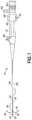
- FIG. 1is a side view of an endoscope
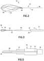
- FIG. 2is a side view of a distal end of an endoscopic tool
- FIG. 3is a side view illustrating extension of the tool shown in FIG. 2 from the distal end of the endoscope shown in FIG. 1 ;
- FIG. 4is a perspective view of a proximal end of the endoscopic tool shown in FIGS. 2-3 ;
- FIG. 5is a schematic view illustrating connections of the sheath and basket device to the assembly shown in FIG. 4 ;
- FIG. 6is an exploded perspective view of the assembly shown in FIG. 4 ;
- FIG. 7is a cross sectional view of the outer sleeve of the assembly shown in FIGS. 4 and 6 ;
- FIG. 8is a cross sectional view of the assembly shown in FIGS. 4 and 6 ;
- FIG. 9is a partial cross sectional view of the top button and plunger shown in FIG. 8 ;
- FIG. 10is a perspective view of the plunger shown in FIGS. 4, 6 and 8 ;
- FIG. 11is a cross sectional view of the plunger shown in FIG. 10 ;
- FIG. 12is a perspective view of an alternate embodiment of the connector shown in FIGS. 4 and 8 ;
- FIG. 13is an exploded perspective view of the connector shown in FIG. 12 .
- the apparatus 10 in this exampleis an endoscope medical device configured to be partially inserted into a patient's body, such as in through the patient's urethra for example.
- the endoscopegenerally comprises a control section 12 and a flexible or semi-flexible shaft 14 connected to the control section 12 .
- the control sectionforms a handle for the apparatus.
- the shaft 14includes a passive deflection section 16 and an active deflection section (bending section) 18 at the distal end of the shaft 14 .
- a control system 22 to control the active deflection section 18extends from the control section 12 to the active deflection section 18 .
- the control system 22generally comprises bending control wires, wire sheaths, and an actuator 28 . The wires are connected to the actuator 28 at one end and are connected to the active deflection section 18 at a second end.
- the control section 12has a user operated slide or lever (control lever) 30 .
- the lever 30is connected to the actuator 28 .
- the actuator 28is adapted to pull and release the wires of the control system 22 .
- the actuator 28may be, for example, a drum or pulley rotatably connected to the control section 12 to pull one wire while releasing the other.
- the actuatormay be any suitable type of device, such as a rocker arm adapted to pull and release the wires of the control system 22 .
- the control sectionwill have additional actuators and corresponding controls to drive the additional pairs of bending control wires.
- the control sectionmay have knobs with rack and pinion mechanisms or other suitable user operated controls for the control system.
- the shaft 14is cantilevered from the control section 12 .
- the flexible shaft 14includes the bending control wires of the control system 22 , a fiber optical image bundle, a fiber optical illumination bundle, and a working channel.
- a port 60 for inserting instruments into the working channel 24 of the shaftis located on the control section 12 .
- the control section 12also has a light source post 62 for connecting a light source (not shown) to the illumination bundle.
- the control section 12has an eyepiece 63 for a user to view an image transmitted by the image bundle from the front end 20 .
- the flexible shaftmay house different systems within.
- the shaft 14generally comprises a frame 26 , a cover 32 and an objective head 34 .
- the tool 36is attached to the apparatus 10 and is configured to extend out of the distal end 20 of the shaft 14 from the working channel 24 .
- the tool 36in this example, is a Surgeon Controlled Basket Device (SCBD).
- SCBDSurgeon Controlled Basket Device
- the tool 36includes an assembly 33 which comprises a basket device 50 and a sheath 56 .
- the basket device 50comprises a basket section 52 at a distal end, and a shaft section 54 extending through the sheath 56 to a proximal end of the tool 36 .
- the shaft section 54functions as a control wire for moving the basket section 52 .
- FIGS. 2 and 3show the shaft section (control wire) 54 moved forward relative to the sheath 56 such that the basket section 52 is located out from a front end aperture 66 of the sheath 56 .
- the basket section 52In the forward position of the sheath 56 on the basket device 50 , the basket section 52 is located inside the sheath 56 ; the basket section 52 being collapsed by the sheath 56 into a smaller shape to fit inside the sheath 56 .
- the tool 36 in this examplecomprises a control assembly 70 .
- the control assembly 70is connected to proximal ends of the basket device 50 and sheath 56 .
- the control assembly 70is configured to be attached to the control section 12 at the port 60 into the working channel 24 .
- control assembly 70comprises an outer sleeve 72 , a connector 74 and a plunger 76 .
- the connector 74is configured to connect the control assembly 70 to the control section 12 at the port 60 .
- the outer sleeve 72is slidably connected to the connector 74 as indicated by arrow A in FIG. 4 .
- the proximal end of the sheath 56is attached to the outer sleeve 72 to longitudinally move the sheath 56 when the outer sleeve 72 is moved.
- the plunger 76is movably mounted to the outer sleeve 72 to also slide as indicated by arrow A.
- FIG. 4shows the plunger 76 is an outward home position relative to the outer sleeve 72 .
- the plunger 76can be depressed into the outer sleeve 72 as indicated by arrow B.
- the proximal end of the shaft section 54 of the basket device 50is attached to the plunger 76 for the plunger to be able to longitudinally move the shaft section 54 of the basket device 50 when the plunger 76 is longitudinally moved.
- the distal end of the basket device 50is extended out of the front end aperture 66 of the sheath 54 .
- the distal end 52 of the basket device 50is retracted towards the front end aperture 66 of the sheath 54 .
- the proximal end of the sheath 56may be connected to the plunger 76 , and a proximal end of the shaft section 54 of the basket device 50 may be connected to the outer sleeve 72 .
- the plunger 76may be depressed from its extended home position towards its depressed position on the outer sleeve 72 to move the sheath 56 over the basket section 52 , and the plunger may be released from its depressed position to its extended home position to move the sheath 56 off of the basket section 52 .
- the control assembly 70comprises two springs 78 , 79 and a top button 80 .
- the top spring 78is located in area 82 of the outer sleeve 72 and the bottom spring 79 is located in the area 83 of the outer sleeve 72 .
- the top spring 78is compressed between surface 92 shown in FIG. 7 and the bottom end 90 of the plunger 76 to bias the plunger 76 in its extending home position relative to the outer sleeve as shown in FIGS. 4 and 8 .
- a top member 88is connected to the top end of the outer sleeve 72 to keep the bottom end 90 of the plunger 76 inside the area 82 .
- the bottom spring 79biases the outer sleeve 72 away from the connector 74 .
- a bottom member 84is connected to the bottom end of the outer sleeve 72 .
- the bottom member 84is adjustably located on the connector 74 .
- the bottom member 84has projections which are configured to engage recesses 86 in the connector 74 to adjustable lock the longitudinal position of the outer sleeve 72 on the connector 74 at one of a plurality of different longitudinal positions of the connector 74 .
- the outer sleeve 72can be axially rotated with the bottom member 84 to disengage from the recesses 86 .
- the outer sleeve 72can be longitudinally slid along the connector 74 to a new longitudinal position.
- the outer sleeve 72can then be axially rotated with the bottom member 84 in an opposite direct to reengage with a new pair of the recesses 86 . This may be used to act as a fine adjustment for moving both the basket device 50 and sheath 56 together relative to the apparatus 10 .
- the top button 80is attached to the top of the plunger 76 .
- the top button 80is adapted to axially rotate on the top of the plunger 76 .
- FIGS. 4 and 6show a top button 80 which covers less than half of the top side of the plunger.
- FIGS. 8 and 9show a top button 80 ′ which covers a majority of the top surface.
- both top buttons 80 , 80 ′function the same way.
- the top buttons 80 , 80 ′provide a top surface for a user's finger to press against, but still allow the plunger 76 to be easily axially rotated on the outer sleeve 72 .
- the plunger 76has a top end 94 .
- the top end 94has finger grooves 96 to provide better frictional engagement with a user's finger(s).
- the top end 94has a hole 98 .
- the top button 80 , 80 ′has a projection 100 which extends into the hole 98 .
- the button 80 , 80 ′is rotatably mounted to the plunger 76 at this projection/hole interface.
- the proximal end of the shaft section 54 of the basket device 50is fixedly connected to the plunger 76 in the channel leading to the hole 98 . However, the shaft section 54 of the basket device 50 is not directly connected to the button 80 , 80 ′.
- the usermay axially rotate the basket device 50 by axially rotating the plunger 76 while the button 80 , 80 ′ and the user's finger on the button do not axially rotate.
- Thisprovides a more comfortable feel to the user's finger and less possibility that the user's finger might slip off of the button/plunger assembly while the plunger is being rotated.
- the above identified example embodimentprovides a tool comprising a first controller and a second controller.
- the first controlleris formed by a plunger and cylinder mechanism comprising the button 80 and the outer sleeve 72 .
- This first controlleris adapted to linearly move the basket device.
- the second controlleris formed by the plunger 76 and is adapted to rotate the basket device independently of the first controller's control of the linear movement or position of the basket device 50 .
- the plunger 76connects the button 80 to the basket device 50 and the cylinder formed by the outer sleeve 72 .
- the connector 102is configured to replace the connector 74 .
- the connector 102generally comprises an extension shaft 104 , and inner insert 106 , a plunger shaft 108 and two buttons 110 .
- the front end 112 of the plunger shaft 108is adapted to be located at the port 60 into the working channel 24 .
- the inwardly facing projections of the bottom member 84 on the outer sleeve 72are located in the grooves 114 .
- the bottom spring 79biases the outer sleeve 72 away from the extension shaft 104 , but the inward projections on the bottom member 84 being located in the grooves 114 keeps the outer sleeve connected to the extension shaft 104 .
- the bottom spring 79may be compressed to move the outer sleeve 72 downward on the outside of the extension shaft 104 . This allows the sheath 56 and basket device 50 to be moved together relative to the connector 102 and apparatus 10 .
- the outer sleeve 72 and attached bottom member 84may be axially rotated on the extension shaft 104 to move the inward projections on the bottom member 84 to rotate into areas 116 to lock the longitudinal position outer sleeve 72 on the connector 102 at a forward location.
- the plunger shaft 108comprises lateral slots 118 and teeth pockets 120 on opposite sides of the slots 118 .
- the slots 118allow for relative movement of the buttons 110 along the longitudinal length of the plunger shaft 108 .
- the teeth pockets 120allow the teeth 122 to engage in the teeth pockets 120 to adjustably lock the position of the buttons 110 relative to the plunger shaft 108 .
- the buttons 110project into the slots 118 through the button holes 124 in the inner insert 106 .
- the buttons 110may be outwardly biased by springs (not shown).
- the buttons 110may be inwardly depressed to move the teeth 112 out of the teeth pockets 120 and allow longitudinal extension or retraction of the extension shaft 104 (with attached inner insert 106 ) along to the plunger shaft 108 .
- This featuremay be used to allow use of the tool with different endoscopes having different length working channels.
- the length of the connector 102can be adjusted to adjust for the different length working channels.
- the toolcan be used with different types of endoscopes.
- an endoscope toolmay be provided having a spin plate, such as the plunger 76 for example, for axially rotating another member, such as a basket device for example.
- a spin platesuch as the plunger 76 for example
- another membersuch as a basket device for example.
- SCBDSurgeon Controlled Basket Device
- SCBDSurgeon Controlled Basket Device
- a mechanismmay be provided which allows the operator's finger to keep pressure on the plunger while the plunger is rotated without subjecting the finger, used to maintain pressure, to the rotation.
- the top surfacewill spin independently relative to the plunger. This allows the plunger to be rotated freely without requiring adjustment by the finger used to apply the downward pressure.
- a top surfacesuch as button 80 or 80 ′ for example, may be attached to the plunger in a manner which holds the top surface steady relative to the plunger in the direction of movement resulting in deployment of the basket (axial direction), but does not link the radial position of the top surface to the radial position or motion of the plunger mechanism. This allows the two components to rotate independent of each other while still maintaining a linear position relationship.
- a tool for use by a surgeon for operating a basket device for capturing an object to be removed from a body of an animalcomprising a first controller adapted to be coupled to the basket device for selectively controlling the basket device and moving the basket device between a first, closed position and a second, open position, the first controller comprising: a plunger and cylinder mechanism; and a handle coupled to the plunger for operating the relative position of the plunger with respect to the cylinder; and a second controller positioned adjacent to the first controller and adapted to be coupled to the basket device for selectively controlling the rotation of the basket device independent of the first controller.
- the toolmay further comprise a sheath having a first end and a second end, the sheath adapted to receive the basket device and to have the basket device longitudinally slide with respect thereto between the first, closed position and the second, open position; and wherein the sheath is coupled to the first controller for translational movement relative to the basket device and the basket device is coupled to the second controller for rotational movement with respect to the first controller.
- the toolmay further comprise a first biasing mechanism operatively located for biasing the plunger with respect to the cylinder to move the basket device toward the first, closed position.
- the toolmay further comprise a locking mechanism coupled to the first controller for locking the plunger in the second, open position. The second controller may remain operative when the locking mechanism locks the first controller.
- the second controllermay continue to rotate the basket device while the first controller is locked.
- the toolmay further comprise a second biasing mechanism for biasing the basket device toward the first, closed position with respect to the handle and the sheath; and wherein the basket device is rigidly rotationally coupled to second controller.
- the second biasing mechanismmay be coupled to the second controller to bias the plunger 76 towards moving the basket to a first, closed position.
- the toolmay further comprise a luer coupler, such as connector 74 for example, for selectively coupling the tool to an endoscope.
- An example embodimentmay be provided in a tool for use by a surgeon for operating a basket device for capturing an object to be removed from a body of an animal, the tool comprising a housing having a longitudinal axis and including a passage; a first controller including a first portion located in the passage in the housing and a second portion extending from the housing; wherein the first controller is adapted to be coupled to the basket device for selectively controlling the basket device and wherein the first controller is axially movable in the passage of the housing for moving the basket device between a first, closed position and a second, open position, and wherein the first controller is rotationally movable in the passage of the housing for rotating the basket device when in the second, open position; and an end surface coupled to the second portion of the first controller wherein the end surface moves axially with the first controller and wherein the end surface moves independently rotationally of the first controller such that the end surface may remain rotationally stationary while the first controller is rotated.
- the toolmay further comprise a sheath having a first end and a second end, the sheath adapted to receive the basket device- and to have the basket device longitudinally slide with respect thereto between the first, closed position and the second, open position; and wherein the basket device is coupled to first controller for translational movement relative to the sheath and wherein the sheath is coupled to housing.
- the toolmay further comprise a first biasing mechanism operatively located for biasing the first controller with respect to the passage in the housing to urge the basket device toward the first, closed position.
- the toolmay further comprise a locking mechanism coupled to the housing for locking the first controller in the second, open position. The first controller may remain rotationally operative when the locking mechanism locks the first controller in the second, open position.
- the toolmay further comprise a luer coupler for selectively coupling the tool to an endoscope.
Landscapes
- Health & Medical Sciences (AREA)
- Life Sciences & Earth Sciences (AREA)
- Surgery (AREA)
- Molecular Biology (AREA)
- General Health & Medical Sciences (AREA)
- Veterinary Medicine (AREA)
- Engineering & Computer Science (AREA)
- Biomedical Technology (AREA)
- Heart & Thoracic Surgery (AREA)
- Medical Informatics (AREA)
- Public Health (AREA)
- Animal Behavior & Ethology (AREA)
- Nuclear Medicine, Radiotherapy & Molecular Imaging (AREA)
- Physics & Mathematics (AREA)
- Biophysics (AREA)
- Optics & Photonics (AREA)
- Pathology (AREA)
- Radiology & Medical Imaging (AREA)
- Orthopedic Medicine & Surgery (AREA)
- Vascular Medicine (AREA)
- Surgical Instruments (AREA)
- Endoscopes (AREA)
Abstract
Description
Claims (12)
Applications Claiming Priority (1)
| Application Number | Priority Date | Filing Date | Title |
|---|---|---|---|
| PCT/IB2016/051346WO2017153806A1 (en) | 2016-03-09 | 2016-03-09 | Endoscope tool |
Publications (2)
| Publication Number | Publication Date |
|---|---|
| US20190069915A1 US20190069915A1 (en) | 2019-03-07 |
| US11172947B2true US11172947B2 (en) | 2021-11-16 |
Family
ID=55642535
Family Applications (1)
| Application Number | Title | Priority Date | Filing Date |
|---|---|---|---|
| US16/081,095Active2036-04-11US11172947B2 (en) | 2016-03-09 | 2016-03-09 | Endoscope tool |
Country Status (6)
| Country | Link |
|---|---|
| US (1) | US11172947B2 (en) |
| EP (3) | EP3416570B1 (en) |
| JP (1) | JP7181085B2 (en) |
| CN (2) | CN114711893B (en) |
| ES (1) | ES2901446T3 (en) |
| WO (1) | WO2017153806A1 (en) |
Families Citing this family (5)
| Publication number | Priority date | Publication date | Assignee | Title |
|---|---|---|---|---|
| US10702280B2 (en)* | 2015-11-10 | 2020-07-07 | Covidien Lp | Endoscopic reposable surgical clip applier |
| EP3416570B1 (en) | 2016-03-09 | 2020-03-18 | Gyrus Acmi Inc., D.B.A. Olympus Surgical Technologies America | Endoscope tool |
| CN108601601B (en)* | 2016-03-10 | 2022-03-08 | 捷锐士阿希迈公司(以奥林巴斯美国外科技术名义) | Surgical tool |
| WO2020052355A1 (en)* | 2018-09-13 | 2020-03-19 | 杭州唯强医疗科技有限公司 | Intravascular foreign body extraction apparatus |
| CN117462188B (en)* | 2023-12-28 | 2024-03-29 | 杭州德晋医疗科技有限公司 | Interventional medical instrument |
Citations (30)
| Publication number | Priority date | Publication date | Assignee | Title |
|---|---|---|---|---|
| GB809773A (en) | 1954-09-16 | 1959-03-04 | S & R J Everett & Co Ltd | Improvements in or relating to syringes |
| US3955578A (en) | 1974-12-23 | 1976-05-11 | Cook Inc. | Rotatable surgical snare |
| US4691705A (en) | 1985-02-08 | 1987-09-08 | Olympus Optical Co., Ltd. | Calculus crushing apparatus |
| US5147303A (en) | 1991-05-23 | 1992-09-15 | Martin Bret C | Disposable safety syringe |
| US5403324A (en) | 1994-01-14 | 1995-04-04 | Microsonic Engineering Devices Company, Inc. | Flexible catheter with stone basket and ultrasonic conductor |
| US5720754A (en) | 1989-08-16 | 1998-02-24 | Medtronic, Inc. | Device or apparatus for manipulating matter |
| JPH10192286A (en) | 1997-01-17 | 1998-07-28 | Asahi Optical Co Ltd | Endoscope treatment tool |
| JPH11113917A (en) | 1998-08-06 | 1999-04-27 | Olympus Optical Co Ltd | Sheath sliding type stone grinding basket |
| US6053934A (en) | 1997-06-02 | 2000-04-25 | Cook Urological, Incorporated | Replaceable, medical device handle |
| US6228023B1 (en)* | 1999-02-17 | 2001-05-08 | Abiomed, Inc. | Tissue pick and method for use in minimally invasive surgical procedures |
| US6419679B1 (en) | 2001-01-17 | 2002-07-16 | Avtar S. Dhindsa | Endoscopic stone extraction device with rotatable basket |
| US20030009176A1 (en)* | 2001-07-05 | 2003-01-09 | Bilitz Mark R. | Medical retrieval device with independent rotational means |
| US20030109889A1 (en)* | 2001-12-12 | 2003-06-12 | Steve Mercereau | Articulating stone basket |
| US6764499B2 (en) | 2000-05-18 | 2004-07-20 | Cook Urological Incorporated | Medical device handle |
| WO2004069059A2 (en) | 2003-02-03 | 2004-08-19 | Scimed Life Systems, Inc. | Apparatus for de-endothelialization of aneurysms and other body lumens |
| JP2005230132A (en) | 2004-02-18 | 2005-09-02 | Asahi Intecc Co Ltd | Medical treatment tool |
| JP2006204745A (en) | 2005-01-31 | 2006-08-10 | Olympus Medical Systems Corp | Endoscopic treatment tool |
| US20080188890A1 (en) | 2006-12-01 | 2008-08-07 | Barry Weitzner | Multi-part instrument systems and methods |
| US20090157060A1 (en) | 2007-12-18 | 2009-06-18 | Teague James A | Multi-functional medical device |
| US7744583B2 (en) | 2003-02-03 | 2010-06-29 | Boston Scientific Scimed | Systems and methods of de-endothelialization |
| US8211115B2 (en) | 2004-05-06 | 2012-07-03 | Boston Scientific Scimed, Inc. | Variable size retrieval basket |
| JP2012161638A (en) | 2006-03-03 | 2012-08-30 | Covidien Ag | System for controlling electrosurgical snare |
| US20130035695A1 (en) | 2010-03-09 | 2013-02-07 | Transcot S.A. | Manually Actuated Function Hose Instrument and Operating Device Therefor |
| US20130211415A1 (en) | 2012-02-09 | 2013-08-15 | Boston Scientific Scimed, Inc. | Steerable tissue manipulation medical devices and related methods of use |
| US8608690B2 (en) | 2005-04-20 | 2013-12-17 | Cook Medical Technologies Llc | Melt-bonded joint for joining sheaths used in medical devices, and methods of forming the melt-bonded joint |
| US20140257253A1 (en) | 2013-03-11 | 2014-09-11 | Boston Scientific Scimed, Inc. | Medical device handles and related methods of use |
| US20160008015A1 (en)* | 2014-07-09 | 2016-01-14 | Boston Scientific Scimed, Inc. | Medical retrieval devices and methods |
| WO2016061297A1 (en) | 2014-10-15 | 2016-04-21 | Cyrus Acmi, D.B.A. Olympus Surgical Technologies America | Surgical tool for removing kidney stone |
| WO2017153806A1 (en) | 2016-03-09 | 2017-09-14 | Gyrus Acmi, Inc. D.B.A. Olympus Surgical Technologies America | Endoscope tool |
| JP2020073196A (en) | 2020-02-18 | 2020-05-14 | ジャイラス・エーシーエムアイ・インコーポレーテッド | Endoscopic instrument |
Family Cites Families (3)
| Publication number | Priority date | Publication date | Assignee | Title |
|---|---|---|---|---|
| CZ297361B6 (en) | 1998-01-30 | 2006-11-15 | Novo Nordisk A/S | Injection syringe |
| EP2109474B2 (en) | 2007-02-05 | 2019-01-30 | Novo Nordisk A/S | Injection button |
| JP6163887B2 (en)* | 2013-06-03 | 2017-07-19 | 住友ベークライト株式会社 | High frequency treatment tool |
- 2016
- 2016-03-09EPEP16713092.1Apatent/EP3416570B1/enactiveActive
- 2016-03-09EPEP19218914.0Apatent/EP3656318B1/enactiveActive
- 2016-03-09CNCN202210201632.9Apatent/CN114711893B/enactiveActive
- 2016-03-09CNCN201680081223.2Apatent/CN108601600B/enactiveActive
- 2016-03-09ESES19218914Tpatent/ES2901446T3/enactiveActive
- 2016-03-09USUS16/081,095patent/US11172947B2/enactiveActive
- 2016-03-09WOPCT/IB2016/051346patent/WO2017153806A1/ennot_activeCeased
- 2016-03-09JPJP2018542138Apatent/JP7181085B2/enactiveActive
- 2016-03-09EPEP21196787.2Apatent/EP3973894B1/enactiveActive
Patent Citations (35)
| Publication number | Priority date | Publication date | Assignee | Title |
|---|---|---|---|---|
| GB809773A (en) | 1954-09-16 | 1959-03-04 | S & R J Everett & Co Ltd | Improvements in or relating to syringes |
| US3955578A (en) | 1974-12-23 | 1976-05-11 | Cook Inc. | Rotatable surgical snare |
| US4691705A (en) | 1985-02-08 | 1987-09-08 | Olympus Optical Co., Ltd. | Calculus crushing apparatus |
| US5720754A (en) | 1989-08-16 | 1998-02-24 | Medtronic, Inc. | Device or apparatus for manipulating matter |
| US5147303A (en) | 1991-05-23 | 1992-09-15 | Martin Bret C | Disposable safety syringe |
| US5403324A (en) | 1994-01-14 | 1995-04-04 | Microsonic Engineering Devices Company, Inc. | Flexible catheter with stone basket and ultrasonic conductor |
| JPH10192286A (en) | 1997-01-17 | 1998-07-28 | Asahi Optical Co Ltd | Endoscope treatment tool |
| US6053934A (en) | 1997-06-02 | 2000-04-25 | Cook Urological, Incorporated | Replaceable, medical device handle |
| JPH11113917A (en) | 1998-08-06 | 1999-04-27 | Olympus Optical Co Ltd | Sheath sliding type stone grinding basket |
| US6228023B1 (en)* | 1999-02-17 | 2001-05-08 | Abiomed, Inc. | Tissue pick and method for use in minimally invasive surgical procedures |
| US6764499B2 (en) | 2000-05-18 | 2004-07-20 | Cook Urological Incorporated | Medical device handle |
| US6419679B1 (en) | 2001-01-17 | 2002-07-16 | Avtar S. Dhindsa | Endoscopic stone extraction device with rotatable basket |
| US20030009176A1 (en)* | 2001-07-05 | 2003-01-09 | Bilitz Mark R. | Medical retrieval device with independent rotational means |
| US20120095477A1 (en) | 2001-07-05 | 2012-04-19 | Bilitz Mark R | Medical retrieval device with independent rotational means |
| US20030109889A1 (en)* | 2001-12-12 | 2003-06-12 | Steve Mercereau | Articulating stone basket |
| US7744583B2 (en) | 2003-02-03 | 2010-06-29 | Boston Scientific Scimed | Systems and methods of de-endothelialization |
| WO2004069059A2 (en) | 2003-02-03 | 2004-08-19 | Scimed Life Systems, Inc. | Apparatus for de-endothelialization of aneurysms and other body lumens |
| JP2005230132A (en) | 2004-02-18 | 2005-09-02 | Asahi Intecc Co Ltd | Medical treatment tool |
| US8211115B2 (en) | 2004-05-06 | 2012-07-03 | Boston Scientific Scimed, Inc. | Variable size retrieval basket |
| JP2006204745A (en) | 2005-01-31 | 2006-08-10 | Olympus Medical Systems Corp | Endoscopic treatment tool |
| US8608690B2 (en) | 2005-04-20 | 2013-12-17 | Cook Medical Technologies Llc | Melt-bonded joint for joining sheaths used in medical devices, and methods of forming the melt-bonded joint |
| JP2012161638A (en) | 2006-03-03 | 2012-08-30 | Covidien Ag | System for controlling electrosurgical snare |
| US20080188890A1 (en) | 2006-12-01 | 2008-08-07 | Barry Weitzner | Multi-part instrument systems and methods |
| US20090157060A1 (en) | 2007-12-18 | 2009-06-18 | Teague James A | Multi-functional medical device |
| US20130035695A1 (en) | 2010-03-09 | 2013-02-07 | Transcot S.A. | Manually Actuated Function Hose Instrument and Operating Device Therefor |
| US20130211415A1 (en) | 2012-02-09 | 2013-08-15 | Boston Scientific Scimed, Inc. | Steerable tissue manipulation medical devices and related methods of use |
| US20140257253A1 (en) | 2013-03-11 | 2014-09-11 | Boston Scientific Scimed, Inc. | Medical device handles and related methods of use |
| US20160008015A1 (en)* | 2014-07-09 | 2016-01-14 | Boston Scientific Scimed, Inc. | Medical retrieval devices and methods |
| WO2016061297A1 (en) | 2014-10-15 | 2016-04-21 | Cyrus Acmi, D.B.A. Olympus Surgical Technologies America | Surgical tool for removing kidney stone |
| WO2017153806A1 (en) | 2016-03-09 | 2017-09-14 | Gyrus Acmi, Inc. D.B.A. Olympus Surgical Technologies America | Endoscope tool |
| CN108601600A (en) | 2016-03-09 | 2018-09-28 | 捷锐士阿希迈公司(以奥林巴斯美国外科技术名义) | endoscopic tool |
| JP2019509090A (en) | 2016-03-09 | 2019-04-04 | ジャイラス・エーシーエムアイ・インコーポレーテッド | Endoscopic instrument |
| EP3416570B1 (en) | 2016-03-09 | 2020-03-18 | Gyrus Acmi Inc., D.B.A. Olympus Surgical Technologies America | Endoscope tool |
| EP3656318A1 (en) | 2016-03-09 | 2020-05-27 | Gyrus Acmi Inc., D.B.A. Olympus Surgical Technologies America | Endoscope tool |
| JP2020073196A (en) | 2020-02-18 | 2020-05-14 | ジャイラス・エーシーエムアイ・インコーポレーテッド | Endoscopic instrument |
Non-Patent Citations (21)
Also Published As
| Publication number | Publication date |
|---|---|
| EP3973894A1 (en) | 2022-03-30 |
| CN114711893B (en) | 2025-09-19 |
| CN108601600A (en) | 2018-09-28 |
| EP3656318A1 (en) | 2020-05-27 |
| EP3973894B1 (en) | 2024-08-28 |
| JP2019509090A (en) | 2019-04-04 |
| EP3416570A1 (en) | 2018-12-26 |
| US20190069915A1 (en) | 2019-03-07 |
| WO2017153806A1 (en) | 2017-09-14 |
| CN108601600B (en) | 2022-03-08 |
| ES2901446T3 (en) | 2022-03-22 |
| JP7181085B2 (en) | 2022-11-30 |
| EP3656318B1 (en) | 2021-10-06 |
| CN114711893A (en) | 2022-07-08 |
| EP3416570B1 (en) | 2020-03-18 |
Similar Documents
| Publication | Publication Date | Title |
|---|---|---|
| US11172947B2 (en) | Endoscope tool | |
| JP5302019B2 (en) | Treatment endoscope | |
| US9456736B2 (en) | Endoscope, and treatment instrument for endoscope | |
| US11311180B2 (en) | Endoscope configured to change a length of a bendable part | |
| US8888687B2 (en) | Method and apparatus related to a flexible assembly at a distal end portion of a medical device | |
| JP6082553B2 (en) | Brake release mechanism and medical manipulator having the same | |
| US11202556B2 (en) | Control of a basket retrieval device | |
| JP2009195694A (en) | Endoscope for treatment | |
| JP6042678B2 (en) | Brake mechanism and medical manipulator having the same | |
| US11344324B2 (en) | Surgical tool for operating a sheath and a wire | |
| CN112469346B (en) | Medical handle | |
| US20090287044A1 (en) | Endoscopic apparatus | |
| JP2016522704A (en) | Surgeon controlled endoscopic device and method | |
| EP2083715B1 (en) | Removable handle for medical device | |
| JP7523606B2 (en) | Endoscopic Instruments | |
| JP2022540883A (en) | Endoscopic Tool Stabilization and Related Uses |
Legal Events
| Date | Code | Title | Description |
|---|---|---|---|
| AS | Assignment | Owner name:GYRUS ACMI, INC. D.B.A. OLYMPUS SURGICAL TECHNOLOGIES AMERICA, MASSACHUSETTS Free format text:ASSIGNMENT OF ASSIGNORS INTEREST;ASSIGNORS:MANSFIELD, RICHARD P.;WALISH, JUDY L.;FEMIA, STEPHEN P.;SIGNING DATES FROM 20180711 TO 20180716;REEL/FRAME:046751/0803 Owner name:GYRUS ACMI, INC. D.B.A. OLYMPUS SURGICAL TECHNOLOG Free format text:ASSIGNMENT OF ASSIGNORS INTEREST;ASSIGNORS:MANSFIELD, RICHARD P.;WALISH, JUDY L.;FEMIA, STEPHEN P.;SIGNING DATES FROM 20180711 TO 20180716;REEL/FRAME:046751/0803 | |
| FEPP | Fee payment procedure | Free format text:ENTITY STATUS SET TO UNDISCOUNTED (ORIGINAL EVENT CODE: BIG.); ENTITY STATUS OF PATENT OWNER: LARGE ENTITY | |
| STPP | Information on status: patent application and granting procedure in general | Free format text:DOCKETED NEW CASE - READY FOR EXAMINATION | |
| STPP | Information on status: patent application and granting procedure in general | Free format text:RESPONSE TO NON-FINAL OFFICE ACTION ENTERED AND FORWARDED TO EXAMINER | |
| STPP | Information on status: patent application and granting procedure in general | Free format text:DOCKETED NEW CASE - READY FOR EXAMINATION | |
| STPP | Information on status: patent application and granting procedure in general | Free format text:NON FINAL ACTION MAILED | |
| STPP | Information on status: patent application and granting procedure in general | Free format text:RESPONSE TO NON-FINAL OFFICE ACTION ENTERED AND FORWARDED TO EXAMINER | |
| STPP | Information on status: patent application and granting procedure in general | Free format text:NOTICE OF ALLOWANCE MAILED -- APPLICATION RECEIVED IN OFFICE OF PUBLICATIONS | |
| STPP | Information on status: patent application and granting procedure in general | Free format text:NOTICE OF ALLOWANCE MAILED -- APPLICATION RECEIVED IN OFFICE OF PUBLICATIONS | |
| STPP | Information on status: patent application and granting procedure in general | Free format text:AWAITING TC RESP, ISSUE FEE PAYMENT VERIFIED | |
| STPP | Information on status: patent application and granting procedure in general | Free format text:PUBLICATIONS -- ISSUE FEE PAYMENT VERIFIED | |
| STCF | Information on status: patent grant | Free format text:PATENTED CASE | |
| MAFP | Maintenance fee payment | Free format text:PAYMENT OF MAINTENANCE FEE, 4TH YEAR, LARGE ENTITY (ORIGINAL EVENT CODE: M1551); ENTITY STATUS OF PATENT OWNER: LARGE ENTITY Year of fee payment:4 |