US11171875B2 - Systems and methods of communications network failure detection and remediation utilizing link probes - Google Patents
Systems and methods of communications network failure detection and remediation utilizing link probesDownload PDFInfo
- Publication number
- US11171875B2 US11171875B2US16/904,277US202016904277AUS11171875B2US 11171875 B2US11171875 B2US 11171875B2US 202016904277 AUS202016904277 AUS 202016904277AUS 11171875 B2US11171875 B2US 11171875B2
- Authority
- US
- United States
- Prior art keywords
- client
- network
- user
- connection
- registration
- Prior art date
- Legal status (The legal status is an assumption and is not a legal conclusion. Google has not performed a legal analysis and makes no representation as to the accuracy of the status listed.)
- Active
Links
Images


Classifications
- H—ELECTRICITY
- H04—ELECTRIC COMMUNICATION TECHNIQUE
- H04L—TRANSMISSION OF DIGITAL INFORMATION, e.g. TELEGRAPHIC COMMUNICATION
- H04L43/00—Arrangements for monitoring or testing data switching networks
- H04L43/08—Monitoring or testing based on specific metrics, e.g. QoS, energy consumption or environmental parameters
- H04L43/0805—Monitoring or testing based on specific metrics, e.g. QoS, energy consumption or environmental parameters by checking availability
- H04L43/0811—Monitoring or testing based on specific metrics, e.g. QoS, energy consumption or environmental parameters by checking availability by checking connectivity
- H—ELECTRICITY
- H04—ELECTRIC COMMUNICATION TECHNIQUE
- H04L—TRANSMISSION OF DIGITAL INFORMATION, e.g. TELEGRAPHIC COMMUNICATION
- H04L12/00—Data switching networks
- H04L12/28—Data switching networks characterised by path configuration, e.g. LAN [Local Area Networks] or WAN [Wide Area Networks]
- H04L12/2801—Broadband local area networks
- H—ELECTRICITY
- H04—ELECTRIC COMMUNICATION TECHNIQUE
- H04L—TRANSMISSION OF DIGITAL INFORMATION, e.g. TELEGRAPHIC COMMUNICATION
- H04L12/00—Data switching networks
- H04L12/28—Data switching networks characterised by path configuration, e.g. LAN [Local Area Networks] or WAN [Wide Area Networks]
- H04L12/2854—Wide area networks, e.g. public data networks
- H04L12/2856—Access arrangements, e.g. Internet access
- H04L12/2863—Arrangements for combining access network resources elements, e.g. channel bonding
- H04L12/2865—Logical combinations
- H—ELECTRICITY
- H04—ELECTRIC COMMUNICATION TECHNIQUE
- H04L—TRANSMISSION OF DIGITAL INFORMATION, e.g. TELEGRAPHIC COMMUNICATION
- H04L41/00—Arrangements for maintenance, administration or management of data switching networks, e.g. of packet switching networks
- H04L41/06—Management of faults, events, alarms or notifications
- H04L41/0654—Management of faults, events, alarms or notifications using network fault recovery
- H04L41/0668—Management of faults, events, alarms or notifications using network fault recovery by dynamic selection of recovery network elements, e.g. replacement by the most appropriate element after failure
- H—ELECTRICITY
- H04—ELECTRIC COMMUNICATION TECHNIQUE
- H04L—TRANSMISSION OF DIGITAL INFORMATION, e.g. TELEGRAPHIC COMMUNICATION
- H04L41/00—Arrangements for maintenance, administration or management of data switching networks, e.g. of packet switching networks
- H04L41/12—Discovery or management of network topologies
- H—ELECTRICITY
- H04—ELECTRIC COMMUNICATION TECHNIQUE
- H04L—TRANSMISSION OF DIGITAL INFORMATION, e.g. TELEGRAPHIC COMMUNICATION
- H04L41/00—Arrangements for maintenance, administration or management of data switching networks, e.g. of packet switching networks
- H04L41/50—Network service management, e.g. ensuring proper service fulfilment according to agreements
- H04L41/5003—Managing SLA; Interaction between SLA and QoS
- H04L41/5019—Ensuring fulfilment of SLA
- H—ELECTRICITY
- H04—ELECTRIC COMMUNICATION TECHNIQUE
- H04L—TRANSMISSION OF DIGITAL INFORMATION, e.g. TELEGRAPHIC COMMUNICATION
- H04L43/00—Arrangements for monitoring or testing data switching networks
- H04L43/08—Monitoring or testing based on specific metrics, e.g. QoS, energy consumption or environmental parameters
- H04L43/0876—Network utilisation, e.g. volume of load or congestion level
- H04L43/0882—Utilisation of link capacity
- H—ELECTRICITY
- H04—ELECTRIC COMMUNICATION TECHNIQUE
- H04L—TRANSMISSION OF DIGITAL INFORMATION, e.g. TELEGRAPHIC COMMUNICATION
- H04L43/00—Arrangements for monitoring or testing data switching networks
- H04L43/50—Testing arrangements
- H—ELECTRICITY
- H04—ELECTRIC COMMUNICATION TECHNIQUE
- H04L—TRANSMISSION OF DIGITAL INFORMATION, e.g. TELEGRAPHIC COMMUNICATION
- H04L45/00—Routing or path finding of packets in data switching networks
- H04L45/22—Alternate routing
- H—ELECTRICITY
- H04—ELECTRIC COMMUNICATION TECHNIQUE
- H04L—TRANSMISSION OF DIGITAL INFORMATION, e.g. TELEGRAPHIC COMMUNICATION
- H04L45/00—Routing or path finding of packets in data switching networks
- H04L45/28—Routing or path finding of packets in data switching networks using route fault recovery
- H—ELECTRICITY
- H04—ELECTRIC COMMUNICATION TECHNIQUE
- H04L—TRANSMISSION OF DIGITAL INFORMATION, e.g. TELEGRAPHIC COMMUNICATION
- H04L45/00—Routing or path finding of packets in data switching networks
- H04L45/74—Address processing for routing
- H—ELECTRICITY
- H04—ELECTRIC COMMUNICATION TECHNIQUE
- H04L—TRANSMISSION OF DIGITAL INFORMATION, e.g. TELEGRAPHIC COMMUNICATION
- H04L47/00—Traffic control in data switching networks
- H04L47/10—Flow control; Congestion control
- H04L47/28—Flow control; Congestion control in relation to timing considerations
- H04L47/283—Flow control; Congestion control in relation to timing considerations in response to processing delays, e.g. caused by jitter or round trip time [RTT]
- H—ELECTRICITY
- H04—ELECTRIC COMMUNICATION TECHNIQUE
- H04L—TRANSMISSION OF DIGITAL INFORMATION, e.g. TELEGRAPHIC COMMUNICATION
- H04L47/00—Traffic control in data switching networks
- H04L47/70—Admission control; Resource allocation
- H04L47/74—Admission control; Resource allocation measures in reaction to resource unavailability
- H—ELECTRICITY
- H04—ELECTRIC COMMUNICATION TECHNIQUE
- H04L—TRANSMISSION OF DIGITAL INFORMATION, e.g. TELEGRAPHIC COMMUNICATION
- H04L47/00—Traffic control in data switching networks
- H04L47/70—Admission control; Resource allocation
- H04L47/76—Admission control; Resource allocation using dynamic resource allocation, e.g. in-call renegotiation requested by the user or requested by the network in response to changing network conditions
- H04L47/765—Admission control; Resource allocation using dynamic resource allocation, e.g. in-call renegotiation requested by the user or requested by the network in response to changing network conditions triggered by the end-points
- H—ELECTRICITY
- H04—ELECTRIC COMMUNICATION TECHNIQUE
- H04L—TRANSMISSION OF DIGITAL INFORMATION, e.g. TELEGRAPHIC COMMUNICATION
- H04L65/00—Network arrangements, protocols or services for supporting real-time applications in data packet communication
- H04L65/10—Architectures or entities
- H04L65/1045—Proxies, e.g. for session initiation protocol [SIP]
- H—ELECTRICITY
- H04—ELECTRIC COMMUNICATION TECHNIQUE
- H04L—TRANSMISSION OF DIGITAL INFORMATION, e.g. TELEGRAPHIC COMMUNICATION
- H04L65/00—Network arrangements, protocols or services for supporting real-time applications in data packet communication
- H04L65/1066—Session management
- H04L65/1073—Registration or de-registration
- H—ELECTRICITY
- H04—ELECTRIC COMMUNICATION TECHNIQUE
- H04L—TRANSMISSION OF DIGITAL INFORMATION, e.g. TELEGRAPHIC COMMUNICATION
- H04L65/00—Network arrangements, protocols or services for supporting real-time applications in data packet communication
- H04L65/1066—Session management
- H04L65/1101—Session protocols
- H04L65/1104—Session initiation protocol [SIP]
- H—ELECTRICITY
- H04—ELECTRIC COMMUNICATION TECHNIQUE
- H04L—TRANSMISSION OF DIGITAL INFORMATION, e.g. TELEGRAPHIC COMMUNICATION
- H04L67/00—Network arrangements or protocols for supporting network services or applications
- H04L67/14—Session management
- H04L67/141—Setup of application sessions
- H04L67/2838—
- H—ELECTRICITY
- H04—ELECTRIC COMMUNICATION TECHNIQUE
- H04L—TRANSMISSION OF DIGITAL INFORMATION, e.g. TELEGRAPHIC COMMUNICATION
- H04L67/00—Network arrangements or protocols for supporting network services or applications
- H04L67/50—Network services
- H04L67/56—Provisioning of proxy services
- H04L67/567—Integrating service provisioning from a plurality of service providers
- H—ELECTRICITY
- H04—ELECTRIC COMMUNICATION TECHNIQUE
- H04L—TRANSMISSION OF DIGITAL INFORMATION, e.g. TELEGRAPHIC COMMUNICATION
- H04L69/00—Network arrangements, protocols or services independent of the application payload and not provided for in the other groups of this subclass
- H04L69/14—Multichannel or multilink protocols
- H—ELECTRICITY
- H04—ELECTRIC COMMUNICATION TECHNIQUE
- H04L—TRANSMISSION OF DIGITAL INFORMATION, e.g. TELEGRAPHIC COMMUNICATION
- H04L41/00—Arrangements for maintenance, administration or management of data switching networks, e.g. of packet switching networks
- H04L41/02—Standardisation; Integration
- H04L41/0213—Standardised network management protocols, e.g. simple network management protocol [SNMP]
- H—ELECTRICITY
- H04—ELECTRIC COMMUNICATION TECHNIQUE
- H04L—TRANSMISSION OF DIGITAL INFORMATION, e.g. TELEGRAPHIC COMMUNICATION
- H04L41/00—Arrangements for maintenance, administration or management of data switching networks, e.g. of packet switching networks
- H04L41/14—Network analysis or design
- H04L41/149—Network analysis or design for prediction of maintenance
- H—ELECTRICITY
- H04—ELECTRIC COMMUNICATION TECHNIQUE
- H04L—TRANSMISSION OF DIGITAL INFORMATION, e.g. TELEGRAPHIC COMMUNICATION
- H04L43/00—Arrangements for monitoring or testing data switching networks
- H04L43/10—Active monitoring, e.g. heartbeat, ping or trace-route
Definitions
- the present technologyrelates generally to communications networks and more specifically to detection and remediation of network failures utilizing link probes.
- Communications networkscan include a collection of nodes where transmission links are connected so as to enable communication between the nodes.
- the transmission linksconnect the nodes together.
- the nodesuse circuit switching, message switching, or packet switching to pass the signal through the correct links and nodes to reach the correct destination terminal.
- Each node in the networkusually has a unique address so messages or connections can be routed to the correct recipients.
- the collection of addresses in the networkis called the address space.
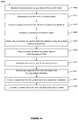
- a method for communications network failure detection and remediationmay comprise: receiving first communications using a network from a first client, the first communications including a telephone number, location, and security credential, the telephone number, location, and security credential each being associated with a first user of the first client; authenticating the first user of the first client using the telephone number and the security credential associated with a first user of the first client; creating, responsive to the authenticating, a registration for the first client in a registration database, the registration including the location from the first communications from the first client, the registration being used to route second communications directed to the telephone number of the first client from a second client; establishing, responsive to the authenticating of the first user of the first client, a connection to the first client; detecting the connection to the first client has failed, the detecting comprising: using a link probe to test connectivity of the first client, resulting in a plurality of connectivity test results of the first client; and utilizing
- a system for communications network failure detection and remediationmay comprise a server, the server including: a processor; and a memory communicatively coupled to the processor, the memory storing instructions executable by the processor to perform a method comprising: receiving first communications using a network from a first client, the first communications including a telephone number, location, and security credential, the telephone number, location, and security credential each being associated with a first user of the first client; authenticating the first user of the first client using the telephone number and the security credential; creating, responsive to the authenticating, a registration for the first client in a registration database, the registration including a telephone number, location, and security credential, the telephone number, location, and security credential each being associated with a first user of the first client, the registration being used to route second communications directed to the telephone number of the first client from a second client; establishing, responsive to the authenticating of the first user of the first client, a connection to the first client; detecting the connection to the first client has failed, the detecting comprising
- a system for communications network failure detection and remediationmay comprise means for receiving first communications using a network from a first client, the first communications including a telephone number, location, and security credential, the telephone number, location, and security credential each being associated with a first user of the first client; means for authenticating the first user of the first client using the telephone number and the security credential; means for creating, responsive to the authenticating, a registration for the first client in a registration database, the registration including a telephone number, location, and security credential, the telephone number, location, and security credential each being associated with a first user of the first client, the registration being used to route second communications directed to the telephone number of the first client from a second client; means for establishing, responsive to the authenticating of the first user of the first client, a connection to the first client; means for detecting the connection to the first client has failed, the detecting comprising: means for using a link probe to test connectivity of the first client, resulting in a plurality of connectivity test results of the first client; and
- FIG. 1is a simplified ladder diagram of a process for making a call, according to some embodiments.
- FIG. 2is simplified block diagram of a network, according to various embodiments.
- FIG. 3is simplified block diagram of a network, in accordance with some embodiments.
- FIG. 4is simplified block diagram of a network, in accordance with various embodiments.
- FIG. 5is simplified flow diagram of a method for monitoring, according to some embodiments.
- FIG. 6is simplified flow diagram of a method for monitoring, according to various embodiments.
- FIG. 7is simplified block diagram of a network, in accordance with some embodiments.
- FIG. 8is simplified flow diagram of a method for evaluation, in accordance with various embodiments.
- FIG. 9is simplified flow diagram of a method for processing multiple events, according to some embodiments.
- FIG. 10is simplified block diagram of a network, according to various embodiments.
- FIG. 11is simplified block diagram of various hub network architectures, in accordance with some embodiments.
- FIG. 12is simplified block diagram of a network, in accordance with various embodiments.
- FIG. 13is a simplified block diagram of a computing system, according to some embodiments.
- FIG. 14is simplified flow diagram of a method of the present disclosure.
- FIG. 15is simplified flow diagram of another method of the present disclosure.
- the users in a conversationare often labeled based on which user initiates the conversation. For example, if a first user wishes to initiate a call to a second user, the first user will be referred to as the “caller” and the second the “called.” Both the caller and the called connect to and interface with the system using one or more user devices.
- the callermay have a desktop phone
- the calledmay have a desktop phone, a mobile phone, a video unit, and the like.
- User devicesare generally two-way. That is, a user may place or receive calls or video sessions (which can include audio and video), and as such may be the caller or the called in any particular session, depending on which user chooses to initiate the conversation.
- the user location capabilityis logically distributed across many entities, which may or may not be physically combined in a number of ways.
- An example systemis the IETF's Session Initiation Protocol (SIP).
- SIPSession Initiation Protocol
- the device(s) representing a usere.g., the user's telephone, video unit, etc.
- UAuser agent
- These UAscan communicate with a centralized entity called a “registrar” (e.g., a central telephony server) which maintains a list of “registrations.”
- Registrationsmap a unique identifier for a (human) user to one or more UAs that may be used to reach that user.
- the identifiermay be a telephone number (e.g., 555-555-1212, for a North American telephone number), a SIP Uniform Resource Identifier (URI) (e.g., sip:user@example.com), a telephone extension, a user name, or some other identifier appropriate for the scope of the system under discussion.
- URIUniform Resource Identifier
- Each registrationtakes the form of an identifier mapping to a list of the location(s) of one or more UAs that can be used to reach the user associated with that identifier.
- the locationis most often in a form that includes one or more of an Internet Protocol (IP) address, IP port, transport protocol (UDP/TCP), and other networking information. When different networking technology is used, other information useful to make the connection may be used.
- IPInternet Protocol
- UDP/TCPtransport protocol
- the locationsare not used directly by the UAs, but rather by another centralized network entity that works on their behalf.
- the caller UAmay not contact the registrar to obtain the address of the called UA (in order to contact it directly), but rather sends any requests to communicate to a SIP “proxy” server.
- the proxycontacts the registrar to obtain the caller's UA location and forwards (“proxies”) the signaling information to the called's UA.
- these two logical entitiesare physically the same device (e.g., are on a common server or even common software application).
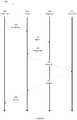
- FIG. 1is a ladder diagram 100 illustrating an example process of making a call.
- FIG. 1shows the exchange of information between four entities—Caller UA 110 , Proxy 111 , Registrar 112 , and Called UA 113 . Time increases from the top of the figure toward the bottom.
- FIG. 1is a simplified representation of the messages exchanged into a logical flow, and does not limit messages which can be exchanged. For example, in SIP, multiple messages make up the acceptance of a request (e.g., 100 TRYING, 180 RINGING, 200 OK, and ACK messages), some occurring prior to and some occurring at the moment the user of the UA indicates they would like to take the call. Similarly, in some cases the proxy may not be present and the UAs may directly contact the registrar. In other cases, multiple proxies may be involved (for example when a user of one organization contacts a user at another organization).
- Caller UA 110the user's device
- Caller UA 110generates one or messages required to initiate a conversation, “inviting” the remote party to a call, and passes these to proxy 111 at step 120 .
- Proxy 111delivers this request to the UA working on behalf of the intended recipient of the call, the called. To locate this UA, Proxy 111 creates a query message, searching for the location(s) of the user identified in Invitation 120 . As discussed above, this identifier could be a phone number, extension, SIP URI, or other identifier, and is provided by Caller UA 110 in Invitation 120 . In the example of a regular phone call, the phone number dialed by the calling user is encoded by Caller UA 110 in invitation 120 . The query containing this identifier is forwarded to Registrar 112 at step 121 . The registrar searches its database, and returns any matching records (locations) in Response 122 . The response includes a location (e.g., IP address and/or similar or related information) needed to reach one or more UAs associated with that identifier.
- this identifiercould be a phone number, extension, SIP URI, or other identifier, and is provided by Caller UA 110 in
- proxy 111forwards the invitation 123 on to the Called UA 113 .
- Called UA 113next alerts the corresponding user, for example by ringing a telephone.
- Called UA 113wishes to take the call and is present.
- the Called UA 113When the user answers (e.g., by lifting the telephone receiver), the Called UA 113 generates one or more messages to indicate accepting the call at step 124 , and sends these to Proxy 111 , which forwards them to Caller UA 110 at step 125 .
- Proxy 111which forwards them to Caller UA 110 at step 125 .
- multiple messagesin both directions
- the processis shown simply as the accept messages 124 and 125 for simplicity.
- Registrationscan, by their very nature, be ephemeral. Certain devices, for example portable devices, may move from one location (and network) to another, and in the process, the IP address for such devices changes. As an example, if a user is running an application on a tablet device that functions as a UA (such as a “soft” phone), the IP address at which that device can be reached will change when the user moves from the office network to home network or onto a mobile provider network. Similarly, devices may be powered off or lose connectivity (resulting in that device no longer being available), or be rebooted (potentially resulting in a different IP address). Additionally, it is often desirable that users can change devices, log in and out of devices, and otherwise have control over specifying which devices can be used to reach them, with minimal administrator involvement.
- protocolssuch as SIP can specify that the devices themselves send registration messages to the registrar to populate the registration database, specifying the address(s) that can be used to reach them, and incorporate expiry times for registrations, allowing older “stale” registrations to be removed.
- a UAWhen a UA is configured, the user inputs their identifier, as well as the location (e.g., IP address) that can be used to reach the registration server. For example, a user may configure a hardware-based telephone or a software application softphone by entering their phone number and the address of the registrar server (often the same server as the proxy that phone will use, although if not both addresses may need to be provided). Additionally, the user typically provides some security credentials (e.g., a password or certificate) associated with the identifier to prevent random individuals from asserting they should be reached when an identifier (e.g., phone number) is contacted. This information also may be entered into a record stored on a configuration or provisioning server, and the device will contact this server to obtain the configuration information.
- security credentialse.g., a password or certificate
- the UAsends a registration message to the registrar, containing the user's identifier and credentials asserting access to that identifier, along with the IP address(es) of the UA.
- the UAalso specifies a preferred expiry time for the registration.
- the registrarverifies the credentials (optionally rejecting the message if the credentials are invalid or not present), and creates a registration mapping in the registration database, associating the user's identifier with the supplied address.
- the registrarwill consider the registration expiry time provided by the UA, and if it is acceptable to the registrar, the current time plus this time will be used to determine how long the registration is valid.
- the registrarmay accept the registration, but substitute an alternate expiry time of its own, which it then sends back to the UA in a message.
- the registrarmay also reject the registration if the time is unacceptable, optionally providing information about what an acceptable time would be.
- expiry timesvary, with times such as 3600 seconds (one hour), 1800 seconds (half an hour) or 600 seconds (10 minutes) being common.
- the UAcan a resend registration messages refreshing the registration periodically, with a period slightly less than the expiry time. For example, if the expiry time is 3600 seconds, the UA may re-register after 3580 seconds have passed. This allows the registrar to know the device is still active and able to receive calls on behalf of the user.
- a user's UA deviceleaves the network in a “clean” way—for example by the user logging out, exiting, or cleanly powering the device down—the UA can send a message to de-register.
- SIPfor example, a new registration message is sent to the registrar with the user's identifier, credentials, the address of the UA, and an expiry time of zero.
- the registrarUpon acceptance by the registrar (after verifying credentials), the registrar will remove the registration. Note that this generally removes only the registration for this device. That is, if the user has two devices registered, only the one being powered down will de-register.
- a UA devicewill no longer be reachable or available but will not cleanly leave and will not de-register. There are many reasons this could occur.
- the UAmay no longer be able to connect to the servers to place calls, and the servers will not be able to direct inbound calls to the UA.
- a devicemay be unplugged, without sending a de-register message.
- a usermay close the cover of a laptop, hibernating the device.
- a software UA (softclient) running on this laptopwould stop suddenly, rendering the softclient unreachable.
- a devicemay also move from one network to another without being shut down or cleanly exiting.
- a softclient running on a tablet or laptopmay be moved from the office to home, changing the network information, including IP address, without the softclient being aware. In this case, because the tablet's IP address changed, the earlier registration is no longer valid.
- VPNis a network construct that provides access to a central network to a remote device, making it function as though that remote device were present on the central network.
- the remote deviceis assigned an IP address on and managed by the central network. Traffic from the device is delivered back to the central network via the VPN. This is typically accomplished by tunneling traffic from the remote device using special protocols back to the central network via a VPN server connected to the central network. The VPN server then delivers the traffic back to the central network. Because the address of the remote device is managed by the central network, this remote traffic from the remote device appears to other devices on the central network to originate from another (trusted) device the central network. Similarly, any traffic sent to the remote device using the central network managed address will be delivered to the VPN server, then relayed to the remote device, again making it appear to be located directly on the central network. This allows a device that is located remotely to participate if it was physically connected to the central network. In a corporate use case, this means a home user's device appears to be connected to a corporate network, with all the access and capabilities that provides.
- the VPN servercan require credentials from the user before allowing a device to connect to the VPN, preventing unauthorized devices from joining the central network. Similarly, traffic over the VPN (tunnel) is often encrypted, ensuring the information from the central network is not leaked to remote devices.
- mechanisms for determining that a network between a provider and the provider's customers has failed or degradedcan be used.
- a failure or degradationis detected, one or more variables are set, indicating the failure or degradation.
- a mechanismmonitors these variables, and takes appropriate pre-defined actions when one or more variables indicates that that action should occur.
- Detection of the failure, as well as the response to the failure being detected,may occur either internally to the customer's network (e.g., on a device connected to the customer network) or externally.
- the customercan be a home or commercial end-user.
- the detectionmay also occur externally to the customer's network.
- the failures or degradationmay be detected by equipment operated by a service provider offering a particular service to the customer, for example a communications service, monitoring of Internet connected devices, or a streaming service.
- the failure or degradationmay also by detected by the customer's ISP (Internet Service Provider), an intermediary network provider, or the provider of service to the service provider.
- ISPInternet Service Provider
- FIG. 2is a simplified block diagram of network 200 connecting a customer (consumer or enterprise) to a service provider.
- the customeraccesses and uses the network via one or more Customer Devices 201 .
- the customermay have computers, tablets, smartphones, or other consumer devices. These devices connect to one or more Customer Network(s) 202 .
- Customer Network(s) 202may take several forms, including wired Ethernet networks, Wireless (Wi-Fi) networks, DECT networks, ZigBee networks, Bluetooth networks, or other network types.
- Customer Network(s) 202can be produced and/or controlled by optional Customer Router 210 and/or a Provider Hub 211 .
- Optional Customer Router 210is a home router device, which is used to allow multiple devices to interface with and use a network connection provided to the customer's ISP. These devices provide access internally using one or more network technologies (e.g., wired Ethernet, Wi-Fi, etc.), typically also provide other capabilities such as firewall, network address translation (NAT), filtering, security, etc.
- network technologiese.g., wired Ethernet, Wi-Fi, etc.
- NATnetwork address translation
- Provider Hub 211can be a device provided and/or managed by a Service Provider 220 .
- Provider Hub 211can provide access to services offered by the service provider, either by the consumer directly interacting with the device, or via one or more of the Customer Devices 201 .
- the service provideroffers communications services (e.g., telephony and/or video services), and the provider hub enables communications devices (telephone handsets, video devices, etc.) on the premises to connect to the service offered by the service provider.
- communications servicese.g., telephony and/or video services
- the provider hubmay have connections to allow analog telephone devices, or DECT wireless telephone devices in the premises (Customer Devices 201 ) to connect to and use the services of the service provider, as well as devices (Customer Devices 201 ) connecting over computer network connections (e.g., Ethernet, Wi-Fi, etc.)
- Customer Devices 201may connect to and use the services of the service provider, as well as devices (Customer Devices 201 ) connecting over computer network connections (e.g., Ethernet, Wi-Fi, etc.)
- the provider hub 211can include many or all of the capabilities of Customer Router 210 , such as providing network access over one or more access technologies, providing security and/or firewall services, etc. As such, in some deployments the customer router is not necessarily needed and the provider hub instead provides these services.
- the Provider Hub 211is connected to one or more Access Network(s) 230 to reach the Internet 232 (and on to Service Provider 220 via the service provider network, not shown).
- one or more Access Device(s) 231may be required between the provider hub and the access network.
- the network service for the customeris provided by a cable company ISP, and the access device takes the form of a cable modem.
- the access networkis a cellular network, for example an LTE network, and the access device is a modem to connect to this network.
- the access deviceis a consumer device featuring a network connection which it can share with other devices. For example, a mobile phone may share its broadband connection with provider hub and/or consumer router as a network connection.
- Access Device(s) 231may not be needed if the components of these devices are integrated directly into Provider Hub 211 and/or Customer Router 210 .
- any combination of stand-alone access device or similar technology integrated into the provider hub or consumer routermay be employed (e.g., a stand-alone access device in the form of a cable modem is connected to the provider hub, and additionally the provider hub features integrated hardware allowing access to a wireless LTE network).
- multiple Access Network(s)are supported simultaneously for reliability, cost-savings, security, or other reasons.
- the deployment described abovewould incorporate a connection using a cable provider ISP network, and an LTE wireless connection. Additional connections are possible, for example a third connection could be provided over a satellite network.
- FIG. 2Customer Router 210 is shown connected to Access Network(s) 230 via Provider Hub 211 (that is, the customer router is “inside” of the provider hub relative to the access network).
- Provider Hub 211that is, the customer router is “inside” of the provider hub relative to the access network.
- FIG. 3illustrates an architecture 300 where the customer router and provider hub are reversed, with the provider hub instead connecting to the access networks via the customer router (that is, the provider hub being “inside” of the customer router relative to the access network).
- one of devices Provider Hub 211 and Customer Router 210may be “behind” the other with respect to one network, but also connected directly to one or more access networks directly.
- FIG. 4illustrates an architecture 400 where this situation occurs.
- the provider hubis “behind” the customer router with respect to the primary network (Access Network(s) 230 via Access Device(s) 231 ), but also has its own connection to Internet 232 via optional Secondary Access Device(s) 240 and Secondary Access Network(s) 241 .
- some Customer Device(s) 201may be connected to the customer router while others (Provider Hub Customer Devices 250 ) are connected via the provider hub.
- Secondary network access via the secondary access networkmay be available only to provider hub customer devices, and not to customer devices.
- An analogous situationexists if Customer Router 210 accesses the primary network via Provider Hub 211 , while accessing its own secondary network directly.
- Secondary Access Device(s) 240may not be required if access capabilities are integrated into Provider Hub 211 .
- Secondary Access Network(s) 241is an LTE and/or other wide area wireless network connection, and Secondary Access Device(s) 240 is integrated into Provider Hub 211 .
- Other topologiescan be used. For example, Provider Hub 211 connecting to the primary network, but Customer Router 210 connecting to its own secondary network.
- failures or degradations in the networkare detected through the mechanisms discussed below. If through one of these mechanisms (“monitoring”) a network is determined to have failed or to have degraded beyond on specific criteria defined below, variables are set, and when the appropriate set of variables are set indicating the failure, one or more pre-defined actions are taken in response to the variables having been set.
- Provider Hub 211is a home hub, and may be used for failure detection.
- detectioncan also be performed by a freestanding, external measurement device on the home network; by Customer Router 210 ; by one of Customer Devices 201 or software operating on a Customer Device; by Access Device(s) 231 ; and/or by remote measurement in cooperation with devices at Service Provider 220 .
- a combination of two or more of the above example devicesis used to obtain the network measurements used to determine if the network has failed.
- FIG. 5shows a simplified flow diagram of a process 500 for setting these variables.
- raw variablesare read and saved and/or cleared without any processing. For example, while some variables may be set to indicate that a failure has occurred, at step 505 , variables are saved with raw measured values. This allows entities taking actions (later) to access raw data without any interpretation by the entity measuring the network information, if required.
- a failure or degradationis indicated (for example, a network failure). This is determined by examining one or more variables to determine if they have degraded beyond a specified criteria. Specific metrics or conditions for determining failure or degradation are outlined below. If at step 510 it is determined that a failure or degradation has occurred, processing moves to step 530 to see if a failure or degradation has cleared (and returns to 505 where the measurements continue to be performed and the status of the network continues to be monitored.) The monitoring process may be continuous, polling-based, triggered by an event, or some other mechanism.
- zero or more variables with more information about the degradation or failuremay be set at step 520 .
- the variablemay include information about the nature of the failure or detected degradation, the severity of the failure, the location where the failure was detected, the entity that detected the failure, etc. In some cases, the variable may not be set due to other conditions (e.g., a measurement that would normally cause a failure flag to be set is overridden by a flag indicating the measurement is suspect of the network is under maintenance). Multiple variables may be set if the condition causes multiple failure types, has occurred at multiple locations, etc.
- variablesmay be cleared in response to the degradation or failure. That is, if some variables previously had been set reflecting a different (for example better) state of the network prior to the detection of the failure or degradation, these may be cleared here.
- step 530After checking if a failure or degradation has occurred, flow moves to step 530 , where it is determined if a failure or degradation has been resolved. If a situation has not resolved (a change of state), processing returns to 505 where monitoring continues to determine if a problem has occurred or been resolved.
- variable(s) set at step 520are cleared. Additionally, at step 550 other variable(s) may be set or cleared in response to the network issue resolving itself. These variables may be analogous to those cleared in step 525 . After completion of this action, the process can return to the beginning (step 505 ) and restart.
- More than one instance of process 500may be running simultaneously/concurrently, monitoring for different network metrics that may trigger setting (or clearing) of variables associated with different network failures or degradations. That is, one process may monitor for loss of connectivity, and set corresponding variables, while another process may simultaneously monitor for high latency, yet another may monitor for high rates of packet loss, etc.
- instances of process 500may be performed in multiple different locations on multiple devices; on customer side equipment (e.g., Customer Device(s) 201 , Customer Router 210 , Provider Hub 211 , or Access Device(s) 231 ); on intermediary network devices (e.g., devices constituting Access Network(s) 230 or Internet 232 ); and/or on devices located at Service Provider 220 . Any of these instances may set or clear appropriate variables.
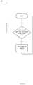
- FIG. 6shows a simplified flow diagram for a process 600 for monitoring and responding to variable(s) set or cleared by process 500 by taking a pre-defined action.
- step 610it is determined if variables which are being monitored have reached pre-defined criteria. This may be a variable being set or cleared; exceeding or falling below a certain value; or being set, cleared or reaching some value in combination with other variables.
- step 610it is determined whether one or more monitored variable(s) have reached the defined criteria. If they have, the process 600 continues at step 620 where the pre-defined action(s) (described in more detail below) are taken in response. If monitored variables have not reached the pre-defined criteria, flow returns to step 610 for further monitoring.
- process 600may be running simultaneously/concurrently, monitoring different variable(s) and/or using different criteria that may trigger taking a pre-defined action in response to the change in variables. That is, one process may take one action when a monitored variable indicates loss of connectivity, and another may take a different action when connectivity returns. As with process 500 , many variable(s) or combinations of variable(s) may be monitored, with different actions associated with different sets or values of variable(s).
- instances of process 600may be performed in multiple different locations on the customer side equipment (e.g., Customer Device(s) 201 , Customer Router 210 , Provider Hub 211 , or Access Device(s) 231 ); may be performed by intermediary network devices (e.g., devices constituting Access Network(s) 230 or Internet 232 ); and/or may be performed on devices located at Service Provider 220 . Any of these instances may take pre-defined responses in response to changes in monitored variable(s).
- the criteria defined at step 610can include detecting whether variables have been cleared, no analogous step is included for when the network returns to the original state—that is handled by setting and/or clearing variables—which will be responded to by different instances of process 600 monitoring those variables to reach certain criteria which indicate the network has returned to proper functionality.
- Failures of network connectivitymay occur at several different levels within the network, or may manifest as failures of different services (e.g., a particular service may fail even when basic network connectivity still operates). Failures at different levels or of different services may result in different actions being taken to deal with the failure. Colloquially, we refer to the failures defined by what has failed from the point of view of the remote location (e.g., in FIG. 2 from the point of view of the Customer Devices 201 or from Provider Hub 211 attempting to reach Service Provider 220 ), and identify these levels within the network based on where failures can occur.
- Connectivity failurescan manifest themselves as an inability to establish a connection between network-enabled devices or services, or an inability to deliver packets (or frames, segment, datagram, or other terms used for sections of data delivered between devices).
- Connectivity failuresrefer to failure of the actual network layer (or lower) connection. This may be because devices on the network are no longer connected to one another physically, for example due to a failed device or the network connection being physically severed. This failure may also be the result of a hardware failure of a device at the link or network levels, causing a failure of packets to be delivered within the network or outside of the network, despite physical connections being sound and all devices being operational. Failure may also occur even with fully functional devices and network links, due to misconfiguration of devices; overload (resulting in dropped packets); security, administrative, or accounting controls; or other conditions that preclude delivery of packets.
- Failuremay occur in several locations. For example, in the architecture presented in FIG. 2 , failure of any of Customer Router 210 , Provider Hub 211 , Access Device(s) 231 , or any device within Customer Network(s) 202 , Access Network(s) 230 , or Internet 232 may cause a connectivity failure.
- DNS failuresrefer to the loss of Domain Name Service (DNS).
- DNStranslates human-readable domain and hostnames (e.g., www.ooma.com) to IP addresses (e.g., 192.230.64.10, 192.230.65.10, etc.), enabling human users to define where packets should be sent.
- IP addressese.g., 192.230.64.10, 192.230.65.10, etc.
- packetsare delivered properly if the IP address is already known.
- the systemis of limited use to users themselves, because they cannot translate human-readable hostnames into IP addresses that can be used by the devices to make network connections and deliver packets (e.g., the role of DNS).
- third-partyIn a third-party failure, tests to see if one or more third-party network sites can be reached fail.
- third-partyrefers to a party that is not the consumer or service provider. For example, tests may be performed to see if major web sites, network providers, or consumer sites are reachable. Failure to reach one (or more convincingly, multiple) third party sites, in the absence of a Connectivity of DNS failure is a strong indication that something in the network connection is not functioning properly or is misconfigured.
- Failure to reach a desired network service(e.g., the service provided by service provider 220 in FIG. 2 ), in the absence of the failures listed above (e.g., Connectivity, DNS, and Third-Party), likely (although not certainly) indicates that that particular service, rather than the network, has failed. For example, if the network appears to be working from a connectivity and DNS perspective, and multiple third-party systems can be reached, failure to reach the service provider likely indicates the service provider or the service provider's network has failed.
- a desired network servicee.g., the service provided by service provider 220 in FIG. 2
- the absence of the failures listed abovee.g., Connectivity, DNS, and Third-Party
- failure to reach the service providerlikely indicates the service provider or the service provider's network has failed.
- Loss of connectivitycan result in numerous issues for an end-user. Obviously, the end-user is deprived of the use of the network for ordinary actions, such as web surfing, exchanging email, using messaging services, streaming media, and other such uses, but a number of particular issues may be more serious for the end-user.
- VoIPVoice over Internet Protocol
- a registrationis used to map a unique identifier for the user (e.g., a phone number, user name, URI, or similar) to a location where the user can be reached (e.g., an IP address).
- a traditional SIP registrationhas an associated expiry time, typically 3600 seconds. If the end-user is unreachable for some reason (for example, because the connection between the service provider and the called end-user has failed, because the end-user equipment has failed, etc.), the service provider may still attempt to deliver the call, only realizing the caller is unavailable after the attempt fails. This may involve lengthy network timeouts, inconveniencing the caller or leading to situations where it is unclear if the call is able to complete.
- Protocols used for communicationsuse mechanisms slightly different than the SIP architecture, but typically with analogous notions of registration allowing a user to be reached by finding the user's unique identifier and mapping that to an address or addresses where the user may be reached.
- One novel example alternate mechanism for registrationis described below.
- the IoTcan include a network of physical devices, vehicles, home appliances, and other items embedded with electronics, software, sensors, actuators, and connectivity which enables these objects to connect and exchange data.
- FIG. 5depicts a simplified flow diagram for a generalized method 500 for monitoring and setting or clearing variables in response to detecting the occurrence or resolution of degradation or failure.
- the various mechanisms that may be used to detect the failuresare described further below. That is, various detection mechanisms which can be used in FIG. 5 are disclosed. Actions/remediation taken in response to the variable(s) being set or cleared are explained later below.
- failuresmay be detected either by components of and/or device(s) in the Service Provider 220 , customer side component and/or device(s), by intermediary devices, and/or by third party devices. Each party may set variables and take actions in response to these variables.
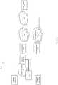
- FIG. 7illustrates a network diagram for deployment 700 , where end-user devices connect to a service provider.
- FIG. 7shows further details of parts of network 200 , illustrating Provider Hub 211 connected to a Service Provider 220 either over VPN 710 , or over Non-VPN Connection 740 .
- FIG. 7further illustrates details of components within Provider Hub 211 and Service Provider 220 .
- embodiments of the present inventionuse traffic other than the registrations flowing between a remote device and a central network to detect abnormalities in the connection, and to inform the registrar of failures of a remote communications device before the registration expires. This may be accomplished directly, for example by sending the registrar a message, or by setting a variable indicating one or more factors indicates a network failure.
- Such detection of abnormalitiescan lead to early detection of unavailability of the remote/other party.
- the registrarWhen the registrar is made aware that this device is unreachable, it will remove registrations for that device after determining if the information provided is sufficient to be certain the device is unreachable. For example, a registration for a telephone that is no longer reachable is removed and delivery of incoming calls will not be attempted for that device. Similarly, other types of failures may be detected, and appropriate actions taken for other services, as described below.
- Provider Hub 211makes a VPN connection to Service Provider 220 via VPN 710 .
- the provider hubincorporates a VPN Client 720 module
- Service Provider 220incorporates a VPN Server 721 module. While the connection here is shown between the provider hub and the service provider, the VPN connection could also originate from and be managed by other customer-controlled devices, such as Customer Devices 201 , Customer Router 210 , Access Device(s) 231 , etc.
- the VPNmay direct packets from a number of different applications (e.g., packets to manage the VPN itself, applications for the Service Provider 220 , other traffic from Customer Devices 201 that requires service provider intervention, etc.) between the service provider and the Provider Hub 211 , there are a number of ways in which loss of the connection may be detected.
- applicationse.g., packets to manage the VPN itself, applications for the Service Provider 220 , other traffic from Customer Devices 201 that requires service provider intervention, etc.
- the VPN Server 721directly detects a failure or abnormality in the network connection to a particular VPN Client(s) 720 , and sets and/or clears one or more variable(s) in response.
- the VPN Server 721explicitly terminates the connection for any of several reasons (e.g., security, authentication, network overload, traffic shaping, or other). For example, if a customer or employee's service is terminated, the VPN server may disconnect any open connections. Similarly, an “abusive” connection—for example one sending excessive traffic, flooding the network with packets, or otherwise disrupting the operation of the network—may be intentionally closed. Since the connection has been terminated, the VPN server explicitly knows that the connection to the VPN Client 720 associated with that VPN connection has been lost, and sets and/or clears one or more variable(s) in response to the connection being terminated.
- reasonse.g., security, authentication, network overload, traffic shaping, or other. For example, if a customer or employee's service is terminated, the VPN server may disconnect any open connections. Similarly, an “abusive” connection—for example one sending excessive traffic, flooding the network with packets, or otherwise disrupting the operation of the network—may be intentionally closed. Since the connection has been terminated, the VPN server explicitly
- VPNsmay be configured to explicitly send “keep-alive” packets between the remote device and the VPN server. These packets are sent explicitly (by the VPN server, remote VPN client, or both) to verify that the connection is still active and information is flowing properly between the two devices. Note that this traffic may or may not be VPN traffic. That is, it may be carried over the tunnel established between the VPN server and the remote device, but may flow over the open Internet between the two devices.
- the frequency that VPN keep-alive packets are sentis configurable in most implementations, but sending the packets every 10 to 30 seconds is typical. After a pre-configured number of keep-alive packets are not seen (for example, 3-5 missed packets), the connection is deemed to have failed or be in a degraded state, and the VPN can be terminated.
- VPN Server 721determines that a connection has failed or become degraded if expected VPN keep-alive packets are not seen.
- Keep-alive packetsmay be sent by each side periodically, and not seeing some predetermined number (e.g., 3) in a row indicates a failure, and the VPN server sets and/or clears one or more variable(s) in response to the failure detected.
- each sideperiodically uses keep-alive messages to determine if the connection is still valid, but rather than simply watching for periodic keep-alive messages from the remote side, keep-alive requests are sent, and responses to keep-alive requests are expected. That is, a poll based approach is used. Failure to receive some number of responses (e.g., 3) to keep-alive requests indicates the other side is no longer connected.
- VPN Server 721fails to see the expected responses, it sets and/or clears one or more variable(s) in response to the failure detected.
- IETF ICMP (ICMP) ping messagesmay be used to achieve the same result, as could any other message sent at regular intervals (including periodic application traffic), so long as the lack of such regular messages is interpreted by the VPN server to indicate loss of connection to the remote party.
- some VPN serversmay monitor the tunnel and determine a connection has failed if traffic of any type is not seen on the connection in a particular interval. That is, if the connection is unexpectedly devoid of traffic for a particular interval, this is interpreted to indicate a failure or degradation.
- This intervalmay be a fixed (or configured) time period, for example 5 minutes, in which no traffic has been seen over the tunnel, or it may be determined that it is statistically unlikely that a connection would have had no traffic in this time period. That is, the system may statistically determine this network link has only a 0.1% chance of not seeing traffic for this duration, and thus determine the link is down. In other words, if a statistical model of the connection shows that the probability of the connection still being open after not seeing traffic on the connection for a certain time falls below a pre-determined threshold, the connection is deemed invalid.
- the remote deviceis connected over a VPN 710 via VPN Client 720 , and VPN Server 721 monitors the connection to see if any traffic has been sent and/or received. If no traffic is seen in a particular fixed or configured interval (e.g., 5 minutes), this fact causes the VPN server to determine that the connection has failed. In response to the detected failure, the VPN server sets and/or clears one or more variables.
- the remote deviceis connected over a VPN
- VPN Server 721monitors the connection to see if any traffic has been sent and/or received. If no traffic is seen for a given duration, a calculation is performed to determine the statistical likelihood that a valid connection would have no traffic for this duration. If the probability that a valid connection would have no traffic falls below a given pre-set threshold, this fact causes the VPN server to determine that the connection has failed, and it sets and/or clears one or more variables in response to the failure detected.
- an additional stepis taken. If the VPN Server 721 determines it is statistically likely the network has failed or become degraded, one or more active checks (e.g., sending ICMP ping requests to the client, sending a VPN keep alive request, or other similar mechanism) are performed to attempt to determine if the connection is still valid before setting and/or clearing the variable(s) in response to the failure detected.
- active checkse.g., sending ICMP ping requests to the client, sending a VPN keep alive request, or other similar mechanism
- FIG. 8is a flow diagram of a method 800 for statistical determination with optional active check. This process can be performed at steps 510 , 520 , and 525 ( FIG. 5 ).
- the systemcan determine how long the connection has been idle.
- a statistical modelcan be used to predict the probability that the connection is still alive if no traffic has been seen in the time determined at step 810 . For example, if it was determined that the connection had seen no traffic in 3 minutes at step 810 , at step 820 the statistic model determines a probability P that a live connection would have no traffic in 3 minutes.
- modelsmay be employed, including ones based on general behavior of all connections the VPN server has seen; behavior from all connections the manufacturer has seen; behavior as predicted in the literature; or other models. Additionally, models may take into account the behavior of this particular user or connection, learning that particular users are more or less “chatty,” and correspondingly, that those connections may have higher or lower probability of being silent for a given interval while still connected.
- a probability threshold T at which a connection is processed as potentially closedcan be retrieved.
- Probability threshold Tis the probability at which it is deemed too unlikely a live connection would have had no traffic for the interval of time seen.
- This valuemay be configured by an operator, configured by the end user, obtained experimentally, or otherwise calculated by the system.
- probability P(from step 820 ) can be compared to probability threshold T (from step 830 ). If probability P is above probability threshold T (e.g., P>T), this implies that the probability of a valid connection being idle exceeds the threshold. If P>T, method 800 proceeds to step 810 (e.g., to continue monitoring the system).
- step 850it is determined if the system is configured to perform an active check to confirm if the connection is alive. If the active check is requested, control proceeds to step 860 to perform the active check. If the active check is not requested, control will continue at step 880 .
- the active testcan be performed, for example, by sending an ICMP ping message, VPN keep-alive message, or similar query to actively determine if the connection is live, but just happened to have no traffic for an extended period.
- controlpasses to step 870 , where it is determined if the check has failed. If the check has not failed, the connection is deemed to be alive (and the time that the connection has been idle is reset to zero), and control passes back to step 810 to monitor the connection to see if it is idle.
- step 870If the active check fails at step 870 , or no active check was requested at step 850 , control moves to step 880 , where it is assumed the connection is dead, because the idle time without traffic was deemed too long.
- step 880e.g., an instance of steps 520 and 525 ) the system sets and/or clears one or more variable(s) in response to failure detected.
- a variablecan be set containing the connection idle time periodically, rather than interpretation being applied while collecting information. This allows pre-defined actions taken (e.g., as described in FIG. 6 ) to determine thresholds at the time actions are taken, rather than relying on the threshold being determined at the time the variable is set.
- VPN Server 721is described as detecting that traffic is not seen flowing over the network, this procedure could also be performed by another device or module within Service Provider 220 which has visibility into network traffic and can determine if no traffic has been seen from the remote side. For example, a core router within the service provider would also be able to monitor the connection for the time it has been idle and take appropriate actions. Any traffic packets flowing over the VPN's connection (e.g., relayed by the VPN server) may trigger these action, explicit testing traffic is not required.
- VPN serversmay also use TCP connection timeout indications to detect failure of the network connection.
- the remote devicee.g., Provider Hub 211 via VPN Client 720
- Service Provider 220is connected to Service Provider 220 over a VPN 710 , and the VPN tunnel is established over a TCP connection.
- acknowledgementsare generated by the receiver for all packets sent over the TCP connection as part of the reliability implemented by TCP.
- TCPis used, if packets are lost, those packets are retransmitted either when the sender fails to see the expected acknowledgement after a given time (timeout) or when acknowledgements of subsequent packets indicate using sequence numbers that one or more intermediate packets have not been received. When just a few packets are lost, these mechanisms can be used to retransmit those (few) missing packets.
- the TCP stackrunning the TCP algorithm, determines the connection itself is dead or not adequate to carry the connection-oriented link, and the application is signaled that the connection is no longer available.
- VPN Server 721receives a signal from the TCP stack and recognizes the remote device is no longer reachable. When this failure is detected, this fact causes the VPN server to determine that the connection has failed, and it sets and/or clears one or more variables in response to the failure detected. Any traffic packets flowing over the VPN's connection (e.g., relayed by the VPN server) may trigger these action, explicit testing traffic is not required.
- VPN Server 721other network failures not expressly described here are detected by the VPN Server 721 , and a network fail variable is set. These include, but are not limited to detecting explicit termination messages from the VPN Client 720 , detecting a failure of the underlying hardware link, etc. Again, in this case the VPN server sets and/or clears one or more variables in response to the failure detected. Other mechanisms for the detection of network failures can be used.
- detection of link layer failuresmay be used to detect remote device connection failures.
- Link layer traffice.g., ARP (Address Resolution Protocol) traffic
- ARPAddress Resolution Protocol
- a network at Service Provider 220 and a remote devicee.g., Provider Hub 211 , Customer Device(s) 201 , and/or Customer Router 210
- the link layer traffice.g., ARP
- ARPAddress Resolution Protocol
- the link layer trafficis also forwarded across the VPN between the remote device entity and the central network entities proxying this link layer traffic.
- an ARP relayis used to extend link-level traffic across the VPN.
- Devices monitoring link layer traffice.g., hosts, routers, switches, etc.
- ARP tables mapping IP address to Ethernet (MAC) addresse.g., IP address to Ethernet (MAC) address.
- devicessend ARP request to verify that devices are still associated with a particular IP address.
- ARP table entries for the remote deviceexpire on various devices in the Service Provider 220 network, these device will send ARP requests asking the remote device to verify it is still associated with the remote device IP, in order to update/refresh the ARP table.
- the ARP relaywill forward this information over the VPN.
- An ARP Entity 724 at Service Provider 220can participate as a link layer device.
- the link layer devicemay be the ARP relay or other link layer devices (e.g., hosts, switches, routers, etc.). If an ARP Entity link layer device in Service Provider 220 finds that an ARP table entry has expired for a particular IP address of a remote device, and the remote device does not respond to the renewal request, the link layer device then determines that the connection for that IP address appears to no longer be available. The ARP Entity then sets and/or clears one or more link-level failure variables in response to the failure detected.
- the remote deviceuses ARP over the ARP relay to find the MAC address of a device in Service Provider 220 , and this fails, this may indicate loss of the network connection. Further tests (e.g., more ARP requests) can be used to determine if the failure is a network failure or simply that the one entity the ARP request was sent to has failed. In either case (e.g., single entity or generalized network failure), the remote device then sets and/or clears one or more link-level failure variables in response to the failure detected.
- Registration messagesindicate that a particular user may be reached at a particular device.
- these registrationshave a finite life time. That is, each registration has an expiration time, and can be refreshed periodically to maintain the registration.
- Contact with a particular useris established to registered device(s) when communications session requests for that particular user are received.
- SIPis used as the protocol between a remote customer device (e.g., Provider Hub 211 , Customer Device(s) 201 , Customer Router 210 , etc.) and a Registration Server 722 at Service Provider 220 .
- Registration messagesare periodically received by the registration server. In the event that a registration message is not received by Registration Server 722 before the expiry time of the registration, the registration server sets and/or clears one or more variables in response to the failure detected.
- Registration Server 722can be an instance of a DNS server used by Service Provider 220 .
- a mapping between the user's ID and the VPN IP address(e.g., the address the end device is reachable over via the VPN) is used to create a DNS entry mapping a user name to an IP.
- a user abc1234 registering IP address 10.1.1.1may result in a DNS entry of abc1234.domain.com mapping to 10.1.1.1. This is used internally to route communications to the end user device when incoming communications requests (calls) reach Service Provider 220 .
- Failure to refresh the VPN connectionresult in failures being detect as mentioned above, but may also cause the registration within the DNS server (e.g., the instance of the registration server) to expire. Accordingly, the registration server (e.g., DNS server) sets and/or clears one or more variables in response to the failure detected.
- the registration servere.g., DNS server
- a protocol, or mechanism other that SIP, or the DNS/VPN approach described aboveis used to handle registration. Failure of the end user device to register periodically, allowing a registration to expire, causes the registration server to set and/or clears one or more variables in response to the failure detected.
- a remote customer devicee.g., Provider Hub 211 , Customer Device(s) 201 , Customer Router 210 , etc.
- Interaction Entity(s) 723is interacting in some way with Interaction Entity(s) 723 at Service Provider 220 , either over VPN 710 or directly over Non-VPN Connection 740 .
- Numerous other interactionsmay be occurring between the customer device and the periodic entity that produce or require interactive traffic to be exchanged. Failures of this exchange may indicate a failure or degradation.
- Interaction Entity(s) 723can be such an entity. It is a part (e.g., process, device, module, etc.) of Service Provider 220 's architecture that expects interaction with one or more customer entities.
- Interaction Entity(s) 723expects regular communication from a remote (customer) device. These communications could be updates sent from the remote device at regular intervals to provide information to the interaction entity, or replies from the remote device to periodic queries from the interaction entity. Similarly, the remote device may expect messages or query responses from the interaction entity. The absence of these communications between the participants is interpreted as a failure of the connection between the interaction entity and the remote device. In the absence of expected interaction traffic, the participants can detect the network failure and set and/or clear one or more variables.
- this informationmay not be reported at regular intervals, but rather as circumstances dictate. For example, information may be sent only when the status of the device changes. Despite information not flowing at regular intervals, statistical models are used to predict the probability that no interaction would be seen within a given time for a live connection. When the probability falls below a pre-defined criteria, this will be interpreted to indicate a network failure or degradation, and one or more variables will be set and/or cleared.
- Interaction Entity 723is a management and/or monitoring server(s). Regular communication is expected between a remote (customer) device and the monitoring and/or management server(s). This communication could be updates sent from the remote device to provide information to the server, replies from the remote device to periodic queries from the server, updates sent from the server to the remote device, or responses from the server to queries from the device.
- the absence of these communications between the participants, either at specific intervals, or at non-specific intervals using a probabilistic model,is interpreted by the management server as a failure of the connection to the remote device. In the absence of expected interaction traffic, the participants can detect the network failure and set and/or clear one or more variable(s).
- the messages or responses exchanged between the remote device and Interaction Entity(s) 723contain status information relating to or measured by the device and/or interaction entity. For example, this could include CPU or processor load, capabilities, resource usage, or other parameters of interest for management.
- the Interaction Entity(s) 723 and/or the devicesmay also periodically measure the latency, bandwidth, or other properties of the network connection between the interaction entity and the remote device by sending probe traffic, and then report this information to the server, the remote device, or other remote devices, as appropriate.
- Other remote monitoring, administrative, or diagnostic messagesmay also be sent, including SMTP messages, remote logging systems, etc. Both the probe traffic itself as well as the exchange of resulting measurements may constitute expected interactive traffic.
- Interaction Entity(s) 723is a security server. Authentication, authorization, credentialing, or other services related to security and access control can be performed between the remote device and the security server(s). Periodically, the remote device provides appropriate credentials, or respond to requests for their credentials, for example, to re-authenticate. In another instance, this information may not be required at regular intervals, but statistical models may be used to detect when traffic should have been seen with high probability, and interpret the lack of traffic as a failure. If this exchange fails at any time, the security server(s) sets and/or clears one or more variable(s) in response to the failure detected.
- Interaction Entity(s) 723is an accounting or billing server. Accounting information can be tracked by the remote device, and either reported (e.g., periodically or at the time of a transaction) to one or more accounting server(s), or the server periodically queries the remote device for accounting information. In another instance, this information may not be required at regular intervals, but statistical models may be used to detect when traffic should have been seen with high probability, and interpret the lack of traffic as a failure. Failure of the remote device to respond or to provide this accounting information when expected causes the accounting server to set and/or clear accounting failed variable(s) in response to the failure detected.
- Presence-based or subscription based solutionscan use subscriptions and/or polling to update the status or “presence” of information of interest across a network.
- a devicemay subscribe to the status (e.g., availability to chat) of a number of other users for an interactive chat system, or to information about physical devices (e.g., open or closed state door) for an alarm system.
- a status server or serversmaintains this information, learning from remote devices when it changes, and relaying these changes to other devices.
- Similar mechanismscan be used to subscribe to voicemail boxes, for example, to see if any voicemail is waiting to be listened to. Polling of voicemail occurs at regular intervals, with the Asterisk SIP server (e.g., a communications system) using a default of 30 seconds for the polling interval.
- Asterisk SIP servere.g., a communications system
- Subscription-based informationis not limited to communications.
- Systemsmay send relevant information to interested parties at regular intervals.
- Camerase.g., “webcams” of sites of interest
- Thesemay send updates when the value changes, periodically, or some combination thereof.
- These interactionscan require communication between the remote device and one or more devices on the central network.
- Interaction Entity(s) 723is a presence or subscription server. Updates of status information, for example, subscriptions, presence information, subscribe/notify, can be exchanged between a remote device and one or more status servers. Any change to the tracked status information is reported either by the remote device (to the status server) or by the status server (to the remote device). Additionally, in some cases, the status values are reported periodically (e.g., every 30 seconds, 10 minutes, etc.) even if they do not change.
- Examples of information that may generate user statusinclude but are not limited to user presence; user idle time; availability of voice, text, e-mail, or other media messages; activity of user (e.g., music being played, show watched, etc.); temperature or weather information; number of users participating in or viewing a session; etc.
- this informationmay not be reported at regular intervals, but statistical models may be used to detect when traffic should have been seen with high probability, and interpret the lack of traffic as a failure. Failure of either the remote device or server to respond or to provide this status information when expected causes the status server and/or remote device to set and/or clear one or more variable(s) in response to the failure detected.
- Interaction Entity(s) 723is an information server.
- the nature of the information produced or consumed by the servercan require updates of other information be reported at regular intervals from the remote device to the server, or from the server to a remote device.
- data of interestmay be sent at regular intervals. Examples include sensors taking readings (e.g., temperature, pressure, sound, humidity, etc.); cameras sending still or video images; microphones sending audio information; consumer electronic devices reporting on their usage, state, or other information (e.g., a cable box reporting channels watched, a music application reporting files played, a video game reporting hours of engagement, etc.); etc.
- this informationmay not be reported at regular intervals, but statistical models may be used to detect when traffic should have been seen with high probability, and interpret the lack of traffic as a failure. Failure of the remote device and/or server to respond to or to provide this information when expected causes the server and/or remote device to set and/or clear one or more variable(s) in response to the failure detected.
- Interaction Entity(s) 723is a communications server, for example a gateway, proxy server, telephony server, soft switch, IP-PBX, etc., communicating with a remote device (e.g., a telephone, communications function in Provider Hub 211 , etc.). While messages needed to establish, maintain, or prepare for communications are exchanged, the device or server fails to send, receive or receive a response from the server or device as expected. In response, the server and/or remote device to set and/or clear one or more variable(s) in response to the failure detected.
- a communications serverfor example a gateway, proxy server, telephony server, soft switch, IP-PBX, etc.
- Interaction Entity(s) 723is an application server, interacting with an application on a remote customer device.
- Applicationsby their nature are expected to generate traffic between the remote device and server at regular intervals. Examples of this type of traffic include database queries; web requests; sending of outgoing email; polling for incoming email; interaction between home automation devices and servers; updates from security device applications including sensors and cameras; social media update; communications to or from digital assistants; connections to stream media; synchronization of data, for example notebooks, shared drives/folders, etc.
- readingstemperature, pressure, sound, humidity, etc.
- camerassending still or video images; microphones sending audio information; consumer electronic devices reporting on their usage, state, or other information (e.g., a cable box reporting channels watched, a music application reporting files played, a video game reporting hours of engagement, etc.); etc.
- this informationmay not be reported at regular intervals, but statistical models may be used to detect when traffic should have been seen with high probability, and interpret the lack of traffic as a failure. Failure of the remote device and/or server to respond to or to provide this information when expected causes the server and/or remote device to set and/or clear one or more variable(s) in response to the failure detected.
- Customer remote devicesfor example Provider Hub 211 , Customer Router 210 , and Customer Devices 201 may track if DNS queries are being resolved properly. If the DNS server is unreachable, unresponsive, or not returning valid results, the device will set and/or clear one or more variable(s) in response to the failure detected, noting that DNS is not functioning properly.
- the devicesets and/or clears the DNS-related variables any time that a DNS query is performed. That is, the variables are set and/or cleared any time DNS is needed during ordinary activity of the device.
- the deviceperiodically performs a DNS query explicitly to determine if DNS service is functional.
- the deviceperforms DNS queries explicitly (only) when ordinary activity has not required a DNS search for a pre-defined period of activity in order to verify DNS is functional.
- the devicein response to the success or failure of the DNS query, the device will set and/or clear one or more variable(s).
- a specific DNS serveris used.
- the specific DNS serveris hosted and located at Service Provider 220 .
- the variables setmay indicate a generalized failure, but may also be indicative of potential connectivity issues to the Service Provider.
- an external serviceis used to provide DNS, and connectivity to it may indicate generalized network failures or connectivity issues to the DNS service provider.
- DNS requestsare sent to the Service Provider, where they are relayed to a DNS service provider.
- failure to resolve a hostname using DNSmay indicate generalized connectivity issues, connectivity issues to the Service Provider, or connectivity issues between the Service Provider and the DNS service provider.
- the devicein response to the success or failure of the DNS query, the device will set and/or clear one or more variable(s).
- Customer remote devicesmay have one or more variables indicating failures of the connection to the Service Provider 220 .
- these variablesmay only indicate that the connection to the service provider does not function.
- a variable indicating failure to reach the service providedmay not confirm the network itself has failed. Accordingly, these devices may also monitor the connection to one or more third-party internet location(s) to determine if these sites are reachable.
- ICMP protocol messagese.g., ping
- specialized transactionse.g., fetching a web page, attempting to stream a video, etc.
- the variable(s) set and/or cleared in response to the testmay indicate which type of test was performed.
- third-partyin this context may vary. In one case, a pre-configured list of third-party entities (e.g., major Internet sites) is used. In another case, any Internet address that is not associated with Service Provider 220 or with the Customer Network(s) 202 is considered a third-party. Determination if an address is part of the customer network may be made, for example, by using the network netmask. Similarly, addresses associated with the Access Network(s) 230 may be filtered and excluded in the case where the device has access to the netmask of the access network. The variable(s) set and/or cleared may indicate information about the specific third-party contacted or other information about the third-party reached.
- third-party entitiese.g., major Internet sites
- any Internet address that is not associated with Service Provider 220 or with the Customer Network(s) 202is considered a third-party. Determination if an address is part of the customer network may be made, for example, by using the network netmask. Similarly, addresses associated with the Access
- the devicesets and/or clears the third-party-related variables any time that a third party is contacted. That is, the variables are set and/or cleared any time a third-party is contacted during ordinary activity of the device.
- the deviceperiodically (explicitly) contacts a third-party location to determine if that third-party is reachable.
- the deviceperforms an explicit test when ordinary activity has not required a connection to a third-party for a pre-defined period of activity to determine third-party reachability.
- the devicein response to the success or failure of the connection to the third-party, the device will set and/or clear one or more variables.
- Various network protocolscan support direct notification of failures (e.g., SNMP), may be used to measure if connectivity is available between locations, and the like.
- SNMPprovides direct reports from devices about failures of connections, which may be used to set and/or clear one or more variable(s).
- direct measurementsmay be taken of connectivity using ICMP protocol capabilities such as ping and traceroute.
- Interactive Connectivity EstablishmentICE may also be used to attempt to open a connection between two devices (e.g., Provider Hub 211 and a destination).
- the results of ICE and/or ICMP testscan indicate connectivity and/or quality of connectivity.
- the IETF's Failure Detection and Locator Pair Exploration Protocol for IPv6 Multihomingprovides additional mechanisms to test for connectivity.
- This protocol and similar protocolsmay be used to set and/or clear one or more variable(s) indicating network failure or degradation.
- failures of multiple remote customer devicesmay be detected. In some embodiments, if a link is severed to a particular neighborhood, failures may be detected for all the remote customer devices in that neighborhood.
- detection of simultaneous or near-simultaneous failures of a number of remote customer devicescauses the detecting entity (e.g., a device in Service Provider 220 , the customer ISP, or an intermediary device) to set variable(s).
- the variablesmay not indicate a failure, but that these devices are correlated in their failure states.
- Algorithms to determine the threshold at which forming a grouping is considered appropriatecan be applied to remove coincidence.
- Variable(s)may be set/cleared to help identify and create groups of end customer devices.
- Detection of groupsmay allow the Service Provider to identify groups of end customer devices associated with particular ISP or intermediary network infrastructure. For example, it may allow determination of which locations for regional networks, to identify which devices are supported by which regional data center, to identify which (potentially geographically or topologically distributed) devices are associated with which distributed load-balancing server, etc. This information can then be stored in variable(s) to improve the performance of the system, as well as to provide unique data for use by Service Provider 220 .
- Groupings of end customer devicesmay also be configured explicitly. If it is known at the time that the system is configured, variables may be set indicating groups of end customer devices belong to a group. For example, based on IP address, it can be determined that a group of end customer devices share a particular ISP, and variable(s) may be set and/or cleared to indicate this.
- Variablesmay be set to indicate multiple groups to which an end customer device belongs.
- groupsmay indicate a particular ISP, particular ISP region, particular geographic region (independent of ISP), etc.
- Such information grouping end customer devicesmay also be stored via other mechanisms, for example, in databases, flat files, etc., and variable(s) are only set and or cleared when failures are encountered, indicating that other end customer devices may also have experienced (or is on longer experiencing) a degradation or failure, because it is in a common group with other end customer devices which have experienced (or is no longer experiencing) a similar failure or degradation.
- pre-defined actionsmay be taken by customer entities, e.g., Customer Devices 201 , Customer Router 210 , Provider Hub 211 , Access Device(s) 231 , or other customer devices; by access network or Internet entities; by entities within Service Provider 220 ; etc.
- customer entitiese.g., Customer Devices 201 , Customer Router 210 , Provider Hub 211 , Access Device(s) 231 , or other customer devices; by access network or Internet entities; by entities within Service Provider 220 ; etc.
- Actionsmay be taken by Service Provider 220 in response to network failure or degradation (or resolution thereof). Actions taken may be performed by the detecting module or device, or the detecting module or device may notify a different module or device within the service provider. For example, VPN Server 721 may detect that a network failure has occurred, but the resultant action may be taken by Registration Server 722 .
- Actionsmay be taken on groups of end customer devices, as well. If a pre-determined number (or percentage, fraction, etc.) of end customer devices within a group have set or cleared variable(s) indicating failure or degradation of the network (or the resolution thereof), actions may be taken for all the end customer devices within that group preemptively. For example, actions are taken for all members of a group, even those that have not detected and set/cleared variable(s) to indicate failure or degradation (or resolution thereof), if a pre-set number, percentage, or fraction have set/cleared variable(s).
- variables for the remaining membersare set/cleared (rather than action taken directly) in response to a pre-determined number, fraction, or percentage of the group indicating failure.
- the remaining membersare directed to test further for the failure condition prior to setting/clearing variables or taking action.
- the setting of network failure variablesis used by the Registration Server 722 to remove a registration for a non-viable communications device, prior to the registration from the device expiring. If the registration server determines that one or more of these variable(s) indicates to the registration server that the connection to the IP address(es) associated with that remote device have been lost, and takes a pre-defined action to remove the registration. Alternatively or additionally, a different entity in Service Provider 220 detects the variable change and takes a pre-defined action to remove the registration. Alternatively or additionally, the VPN server 721 notices the variable change itself and takes a pre-defined action to remove the registration.
- a different communications server or deviceobserves that variables have been set indicating failure, and takes a pre-defined action to remove the registration.
- the pre-defined action to remove the registrationmay vary, depending on implementation.
- the actionis to send a message to the registration server, asking it to remove the registration.
- a message, command, instruction or direct interactionis used to remove the registration from the database or other data store (e.g., DNS server, flat file) used to store registrations.
- the pre-defined actionmay include other steps beyond removing the registration.
- the Registration Server 722sends a message to the remote device indicating it has been de-registered. This forces the device to re-register if it is available.
- this messageis sent by another entity in Server Provider 220 on behalf of the registration server.
- the deviceis one of Provider Hub Customer Devices 250 as shown in FIG. 4 .
- a message indicating the device has been deregisteredis sent over Secondary Access Network(s) 241 , allowing the message to be received even if Access Network(s) 230 has failed, potentially allowing the device to re-register over the secondary network.
- the Registration Server 722sends a message to user of the remote device indicating it has been de-registered. This allows the user to investigate the cause of the problem and potentially correct the issue. Additionally or alternatively, this message is sent by another entity in Server Provider 220 on behalf of the registration server.
- the messagemay be sent in many forms, including a phone call or text message to a telephone number (different than the one with the failed registration); email; push notification in mobile application (potentially over a secondary network such as 4G); as a message over another secondary network; or other mechanism specified by the user or service provider.
- variable set by VPN Server 721 indicating a connection has been terminatedcan be a clear indication a remote device is unreachable, in other cases multiple variables may be consulted prior to removing a registration.
- a network monitoring server or accounting server losing connection with a remote devicemay indicate network failure, but may also indicate that the remote device's monitoring software has crashed or the accounting server has encountered an error.
- the failurelikely indicates the device connection is down, but could also indicate the relay has failed.
- Such determinations based on other network trafficmay be made regardless of whether the connection to the remote device takes place over VPN 710 or over a direct, network connection such as Non-VPN Connection 740 .
- FIG. 9illustrates a flow diagram of an example method 900 for processing multiple events to determine if a pre-defined action of removing a device registration is appropriate.
- the devicecan be connected over VPN 710 , and VPN Server 721 may not have set flags indicating that the connection has been explicitly broken. This is a particular instance of the flow illustrated by FIG. 6 .
- This processmay be run by Registration Server 722 or another entity at Service Provider 220 .
- the variables tracking the status of VPN keep-alive traffic and connection traffici.e., has the connection been idle too long
- other variablescan be used.
- the systemcan obtain the variable(s) tracking the state of the keep-alive packet traffic monitoring. Note that this can be monitored separately (and variable(s) set and/or cleared) in an action not shown in FIG. 5 , and at this step the system is checking if the variables are set indicating keep-alive packets are being received/responded to as expected.
- the systemcan determine if variables reflecting time since the last traffic flowing through the tunnel is currently indicating a valid connection. As before, this is checking the current status, and the setting and/or clearing is handled elsewhere. In this case, the process of detecting this property and setting the connection idle fail variable to true is detailed above in relation to FIG. 8 .
- step 930additional variables can be obtained and checked to see if they indicate the connection is broken. These variables correspond to any other connection status information devices within Service Provider 220 may obtain (e.g., link failure information, information from Interaction Entity(s) 723 , etc.).
- connection state variablesindicate a connection failure has occurred. If not, method 900 returns to step 910 and monitoring of the variables continues.
- Step 940may consist of checking a Boolean value of a variable (e.g., is a variable indicating a failure set), and/or raw variables (e.g., set at step 505 ) may be used to make more sophisticated determinations.
- the connection idle variablemay indicate failure, but raw values may be consulted by the entity executing method 900 to decide if the determination criteria used to set the failure variable is acceptable.
- the failure variable set in Process 800may not be used, and the raw variable(s) set in step 505 may be used instead.
- the variable(s)may indicate insufficient information, and additional measurements (e.g., active probes) may be used to supplement the variable(s) collected.
- step 940If at step 940 a variable (is determined to) indicate failure/degradation, method 900 proceeds to step 950 , where the pre-defined action(s) discussed above are taken in response to determining that relevant variables have been set.
- An expiry mechanism built into communications registration protocolscan help to handle failure or unclean exit scenarios, but may not be perfectly predictive. Because the expiry times are frequently quite long, there is opportunity for failure. If the end user device registers and failure or unclean exit occurs prior to the expiry time, then the servers will be unaware the device is available. In such cases, the server may erroneously believe the end user device is still capable of accepting calls and behave improperly. For example, while the servers may be configured to redirect incoming calls to voice mail if no device is available to service the user's call, if the servers believe the device is still available, then this behavior may fail or be delayed while the server attempts to reach a non-reachable device. Some embodiments, by monitoring other variable(s), can advantageously more rapidly detect failed or unreachable devices, resulting in a more reliable communications system.
- the detecting entitywhen one or more monitored variable(s) indicates a network failure or degradation (e.g., independent of communications devices and/or registrations for communications devices), the detecting entity sends a message to user that the connection has been lost. This allows the user to investigate the cause of the problem and potentially correct the issue.
- the messagemay be sent in many forms, including a phone call or text message to a telephone number (e.g., different than the one with the failed registration); email; push notification in mobile application; out-of-band (e.g., second network) notification; or other mechanism specified by the user or service provider.
- the service associated Service Provider 220is a critical service, for example security monitoring, health monitoring, or a similar service that cannot be interrupted.
- a command or monitoring centercan be notified.
- the detecting entitysends a message to the command or monitoring center that the connection has been lost. This allows the command or monitoring center to take other actions, including notification of the customer, and/or sending an appropriate response.
- the serviceis an alarm monitoring service.
- the loss of connectionis detected, the service attempts to contact the user to determine if there is a threat, and if the user indicates there is or cannot be reached, police or security are dispatched to investigate.
- one or more devices on the customer networkare connected to more than one network.
- the illustrated provider hubis an example of such a configuration.
- the provider hubhas access to Access Network(s) 230 , in this case via Customer Router 210 and Access Device(s) 231 .
- Provider Hub 211has access to Secondary Access Network(s) 241 via Secondary Access Device(s) 240 .
- Other architecturesare possible, including both networks being connected to the provider hub, networks where the customer router connects to the primary network via the provider hub but has a secondary network, networks where the customer router has both connections, and other architectures. Different devices featuring the secondary connection can be used.
- an entity in Service Provider 220contacts the customer device equipped with a secondary network over the secondary network.
- the remote devicemay (initially) be unaware that the connection is not working properly, but is made aware via the secondary network connection.
- the remote devicemay then use the secondary network, both to contact Service Provider 220 , as well as optionally for other services.
- the secondary networkis combined with customer notification, as a mechanism to inform the customer that the primary network has failed.
- Provider Hub 211own address is used as the address of the server to resolve DNS requests. This allows DNS requests to be proxied as desired by the Provider Hub.
- the Provider Hubmay then direct requests to the Service Provider 220 , to an alternate DNS service provider, to a well-known public DNS server (e.g., Google's 8.8.8.8 DNS service), or to an ISP or other service provider DNS server.
- a well-known public DNS servere.g., Google's 8.8.8.8 DNS service
- the addresses of a DNS server located at the Service Provider 220of an alternate DNS service provider, of a well-known public DNS server (e.g., Google's 8.8.8.8 DNS service), or of an ISP or other service provider DNS server is used (instead of the Provider Hub 211 's address).
- a DNS server located at the Service Provider 220of an alternate DNS service provider, of a well-known public DNS server (e.g., Google's 8.8.8.8 DNS service), or of an ISP or other service provider DNS server is used (instead of the Provider Hub 211 's address).
- the Provider Hubprovides the DNS server address(es) to clients (e.g., Customer Devices 201 and/or Provider Hub Customer Devices 250 ) directly using DHCP at the time the devices request a network address.
- clientse.g., Customer Devices 201 and/or Provider Hub Customer Devices 250
- Customer Router 210provides the DNS server address(es) to clients.
- the Customer Routermay itself obtain the DNS server address from the Provider Hub or may be pre-configured to provide one of the addresses discussed above.
- an external DHCP serverprovides the DNS server address to the clients.
- one or more devicesare hard-coded or pre-configured to provide one of the addresses above.
- the network configurationis such that the DNS server used is located at Service Provider 220 , or at a DNS service provider and relayed via the Service Provider.
- an alternate DNS servermay be specified (e.g., directly to DNS service provider, an alternate DNS service provider, a well-known public DNS server (e.g., Google's 8.8.8.8 DNS service), or an ISP or other service provider DNS server may be specified.
- a DNS server other than one located at Service Provider 220or DNS service provider and relayed via the Service Provider is used.
- an alternate DNS servermay be specified (e.g., directly to DNS service provider, an alternate DNS service provider, a well-known public DNS server (e.g., Google's 8.8.8.8 DNS service), or an ISP or other service provider DNS server specified.
- Provider Hub 211performs the DNS resolution on behalf of clients (e.g., Customer Devices 201 and/or Provider Hub Customer Devices 250 ) which are given the Provider Hub's address as the DNS server via DHCP (from Provider Hub 211 , Customer Router 210 , or some other DHCP server).
- clientse.g., Customer Devices 201 and/or Provider Hub Customer Devices 250
- the Provider Hubuses the alternate address to perform DNS lookups on the client's behalf.
- clientsare provided the DNS server address as part of the DHCP process. In that case, newly connected clients and those renewing their DHCP leases will obtain the new DNS server address.
- short duration DHCP leases(e.g., 5 minutes) may be used as a mechanism to ensure that clients will be forced to renew their lease, more rapidly obtaining a new DNS server in the event of failure.
- Provider Hub 211own address is used as the address of the server to resolve DNS requests. This allows DNS requests to be proxied as desired by the Provider Hub.
- the Provider Hubmay then direct requests to the Service Provider 220 , to an alternate DNS service provider, to a well-known public DNS server (e.g., Google's 8.8.8.8 DNS service), or to an ISP or other service provider DNS server.
- a well-known public DNS servere.g., Google's 8.8.8.8 DNS service
- the addresses of a DNS server located at the Service Provider 220of an alternate DNS service provider, of a well-known public DNS server (e.g., Google's 8.8.8.8 DNS service), or of an ISP or other service provider DNS server is used instead of the Provider Hub 211 's address.
- a DNS server located at the Service Provider 220of an alternate DNS service provider, of a well-known public DNS server (e.g., Google's 8.8.8.8 DNS service), or of an ISP or other service provider DNS server is used instead of the Provider Hub 211 's address.
- the Provider Hubprovides the DNS server address(es) to clients (e.g., Customer Devices 201 and/or Provider Hub Customer Devices 250 ) directly using DHCP at the time the devices request a network address.
- clientse.g., Customer Devices 201 and/or Provider Hub Customer Devices 250
- Customer Router 210provides the DNS server address(es) to clients.
- the Customer Routermay itself obtain the DNS server address from the Provider Hub or may be pre-configured to provide one of the addresses discussed above.
- an external DHCP serverprovides the DNS server address to the clients.
- one or more devicesis hard-coded or pre-configured to provide one of the addresses above.
- the network configurationis such that the DNS server used is located at Service Provider 220 , or at a DNS service provider and relayed via the Service Provider.
- an alternate DNS servermay be specified (e.g., directly to DNS service provider, an alternate DNS service provider, a well-known public DNS server (e.g., Google's 8.8.8.8 DNS service), or an ISP or other service provider DNS server may be specified.
- a DNS server other than one located at Service Provider 220or DNS service provider and relayed via the Service Provider is used.
- an alternate DNS servermay be specified (e.g., directly to DNS service provider, an alternate DNS service provider, a well-known public DNS server (e.g., Google's 8.8.8.8 DNS service), or an ISP or other service provider DNS server specified.
- Provider Hub 211performs the DNS resolution on behalf of clients (e.g., Customer Devices 201 and/or Provider Hub Customer Devices 250 ) which are given the Provider Hub's address as the DNS server via DHCP (from Provider Hub 211 , Customer Router 210 , or some other DHCP server).
- clientse.g., Customer Devices 201 and/or Provider Hub Customer Devices 250
- the Provider Hubuses the alternate address to perform DNS lookups on the client's behalf.
- clientsare provided the DNS server address as part of the DHCP process. In that case, newly connected clients and those renewing their DHCP leases will obtain the new DNS server address.
- short duration DHCP leases(e.g., 5 minutes) may be used as a mechanism to ensure that clients will be forced to renew their lease, more rapidly obtaining a new DNS server in the event of failure.
- one or more devices on the customer networkis connected to more than one network.
- the illustrated provider hubis an example of such a configuration.
- the provider hubhas access to Access Network(s) 230 , in this case via Customer Router 210 and Access Device(s) 231 .
- Provider Hub 211has access to Secondary Access Network(s) 241 via Secondary Access Device(s) 240 .
- Other architecturesare possible, including both networks being connected to the provider hub, networks where the customer router connects to the primary network via the provider hub but has a secondary network, networks where the customer router has both connections, and other architectures. Different devices featuring the secondary connection can be used.
- actionscan be taken to make use of the secondary network. As described above, this may also be performed upon notification from the Service Provider 220 that it is no longer receiving communications from the device.
- the user device equipped with one or more secondary networksmaintains a prioritized list of which connections are preferred for use.
- a Provider Hub 211may have an Ethernet broadband connection, an LTE to another network provider, and a Wi-Fi connection to a consumer device with a separate network connection (e.g., a tablet that can provide a hotspot via Wi-Fi to the tablet's service provider).
- a separate network connectione.g., a tablet that can provide a hotspot via Wi-Fi to the tablet's service provider.
- the deviceprefers to use them in that order.
- the devicewill try the next connection on the list. If that one fails, the next connection will be attempted.
- any earlier (higher priority) connectionsare re-tried before moving to a lower priority network. For example, if the Ethernet connection above fails, the device will try the LTE connection. If this also fails, the Ethernet connection may be retried before moving to the Wi-Fi connection.
- the secondary networkwhen a failure or degradation is detected, is used in addition to, rather than in place of the primary network, as a bonded connection.
- multipath protocolse.g., IETF MPTCP
- techniquese.g., MPUDP
- the Provider Hub 211and the traffic destination.
- Theseare used to send traffic for a single application and source/destination pair over multiple network paths simultaneously.
- the primary networke.g., Access Network(s) 230
- variables indicating network performanceindicate failure or degradation, in which case some or all traffic is routed over the secondary network (e.g., Secondary Access Network(s) 241 ).
- the secondary networke.g., Secondary Access Network(s) 241
- both the primary and secondary networkare used, but a much smaller fraction is sent using the secondary network unless variables indicate failure or degradation of the primary network, at which point an increasing portion (up to all) of the traffic is moved to the secondary network.
- this approachis combined with the prioritized list described above. If the primary network does not meet performance goals, the first secondary network is used to provide improved performance. If the bonded network is still not meeting performance criteria, additional networks from the list are bonded to improve performance.
- variables being set and/or cleared in response to changes in the behavior of the original (primary) networkare used to return to using the primary network.
- Method 500 in FIG. 5illustrates an example part of this process.
- variableshave been set and/or cleared in response to failure or degradation of the network, and the process is monitoring the network to see if the problem has resolved. If the problem has resolved, appropriate variables are cleared and/or set at steps 540 and 550 .
- method 500can be active (e.g., probing the network to see if it has improved) or passive (e.g., watching behavior of existing traffic).
- Method 500can be triggered by events (e.g., observing traffic on a network after a period of no traffic, obtaining a link indication, etc.) or by polling periodically to check network behavior.
- An embodiment of method 600is a process that monitors variables used to indicate that a network has improved. If this process detects that those variables that indicate the network has improved are set and/or cleared at step 610 , the pre-defined actions taken at step 620 will move to determine if traffic should be moved back to the primary network (based on configuration, user-preference, service provider preference, etc.).
- each network on a prioritized listis periodically monitored, and if a higher priority network has returned to connectivity and/or improved from a degraded state, as indicated by variables, the higher priority network will again be used subject to user, service provider, or configuration settings.
- variables from other end customer devices in the same group as the primary network connectionare used to help determine when to return to the primary network. If several other end customer devices in the same group (e.g., on the same ISP, on the same ISP access device, etc.) indicate that their primary network has returned, the system instructs the end customer to device to either return to the primary network or to test the primary network to potentially return to it.
- the impact of improved performance variables for the primarymay be to remove a lower-priority bonded network, to route more traffic over the primary network, to cease bonding, or some combination of these actions.
- Bondingcan be performed using two or more networks (channels) to send data—split among the networks—resulting in greater (combined) bandwidth than one network alone. Bonding was described above in relation to FIG. 4 .
- the above techniquesmay be used to switch between two different secondary networks as well, in scenarios where more than one secondary network is employed. For clarity, switching back to the primary network is described, but this mechanism can also be used to move between different secondary networks. For example, a primary network, preferred secondary network, and back-up (less preferred) secondary network are connected. If both the primary and preferred secondary network are degraded or disabled, traffic may flow over the back-up secondary network.
- the mechanisms described abovemay be used to determine that the preferred secondary network has become available, not just to determine that the primary network has become available.
- variable(s)indicate degradation or failure of the primary network
- the performance of one or more secondary networksis tested (e.g., via active probing or testing such as latency tests, speed tests, connectivity tests, etc.) before traffic is moved to one or more secondary network(s) or before one or more secondary network(s) is bonded to improve performance. This ensures that the networks are adequate or an improvement before moving traffic, and that moving to a secondary network does not reduce performance.
- active and/or passive monitoringis used for the primary network and one or more secondary network(s) at all times.
- Variable(s)are set and refreshed periodically, allowing decisions about switching and/or bonding secondary network(s) to be made immediately after variable indicate failure and/or degradation of the primary network, rather than waiting for active testing to be performed.
- these testsmay be active testing (such as latency tests, speed tests, connectivity tests, etc.), but if any traffic is flowing over the connections, such testing may also be performed passively or parasitically with existing traffic.
- the primary network and/or other secondary network(s)may be tested (e.g., again, by active probing or testing such as latency tests, speed tests, connectivity tests, etc.) prior to moving traffic back to the primary network or changing the blend of traffic across a bonded connection.
- the end customer(user) is presented with the information related to variables set and/or cleared related to performance of the primary network and secondary network(s).
- the end customercan actively make decisions about when to switch automatically.
- the useris prompted to make the decision themselves when the network degrades below a certain level, and similarly is prompted to make the decision themselves to return when performance improves.
- the end useris able to adjust bonding parameters manually in response to information about degradation and/or failure of one or more networks, as conveyed by variable(s).
- one or more variable(s)indicates a need to have end customer devices communicate with either a different server or with servers in a different data center location. This may be determined based on variables set by the end customer device, ISP, or intermediary, for example by noticing that the service is unreachable. This may also be determined by the service provider, for example via variable(s) indicating that a particular data center is undergoing maintenance or noticing that a particular customer has changed ISPs and a different server or data center would improve performance.
- variable(s)indicate that an end user device should move to a different server and/or data center.
- the determinationis made by a device at or under control of the service provider. Instructions are sent to the end customer device directing it to move connections to the new data center and/or server. Alternatively or additionally, messages are sent to the data center and/or server the end customer device is currently associated with, instructing it to terminate the connection, forcing the end customer device to reconnect, potentially to a different data center and/or server.
- variable(s)indicate that an end user device should move to a different server and/or data center.
- the determinationis made by the end customer device, the end customer's ISP, or an intermediary device.
- the end user deviceconnects to a second data center and/or server in response.
- the new server and/or data centermay be pre-provisioned, or the end user device may contact the service provider in some way to determine the location for a new data center and/or server.
- FIG. 10is a block diagram showing architecture 1000 for performing secondary network connection that advantageously allows more end user devices to take advantage of the secondary network.
- Architecture 1000has at least some of the characteristics of architecture 400 of FIG. 4 .
- Provider Hub 211is “behind” the customer router with respect to the primary network (e.g., Access Network(s) 230 via Access Device(s) 231 ), but also has its own connection to Internet 232 via optional Secondary Access Device(s) 240 and Secondary Access Network(s) 241 .
- some Customer Device(s) 201may be connected to the customer router while others (e.g., Provider Hub Customer Devices 250 ) are connected via the provider hub.
- secondary network access via the secondary access networkmay be available only to provider hub customer devices, and not via customer devices.
- Provider Hub 211is disposed “outside” the network. That is, having Customer Router 210 connect to Provider 211 to reach the primary Access Network(s) 230 . However, end users may be unwilling to configure their network in this way.
- Connection 1001some other sort of connection allowing Customer Router 210 to access the secondary connection of Provider Hub 211 , shown here as Connection 1001 , is used.
- This connectionmay take several forms.
- Customer Router 210incorporates a USB connection and logic to use the USB connection to connect a secondary network device.
- the customer routermay be designed to allow a USB LTE modem to be connected and used as a secondary network. Because Service Provider 220 already provides Secondary Access Network 241 service via Provider Hub 211 , it may not be desirable to purchase a USB LTE modem and connect it to the customer router.
- Provider Hub 211can include a USB connection, which is connected to Customer Router 210 over Connection 1001 , in this case a USB connection.
- a USB connectionBy emulating the behavior of a USB LTE modem (or other modem technology supported by the customer router), Provider Hub 211 can be used to provide backup network capabilities to the customer router. In this scenario, both Provider Hub Customer Devices 250 and Customer Devices 201 are able to use the secondary network.
- USB On-the-GoUSB On-the-Go
- USBGOUSB On-the-Go
- connection between Provider Hub 211 and Customer Router 210is via Bluetooth (i.e., Connection 1001 is a Bluetooth connection), rather than USB.
- Bluetoothis used as a data connection, allowing Customer Router 210 to access the secondary network connection (via Secondary Access Network(s) 241 ) offered by Provider Hub 211 .
- connection 1001is a serial connection
- connection 1001is a (RS-232) serial connection
- Wi-Fi connectionis a Wi-Fi connection
- other commonly used connection technologyis used for Connection 1001 .
- Provider Hub 211presents itself over connection 1001 as a router for one network technology (e.g., LTE router) that Customer Router 210 is compatible with, while Secondary Access Network(s) 241 is actually a different network technology (for example, a secondary Ethernet broadband connection). In this way, the customer router can be used with any secondary network technology supported by Provider Hub 211 .
- one network technologye.g., LTE router
- Secondary Access Network(s) 241is actually a different network technology (for example, a secondary Ethernet broadband connection).
- the customer routercan be used with any secondary network technology supported by Provider Hub 211 .
- Connection 1001is a wired connection, for example a USB, serial, or similar cable.
- the connectionis a wireless connection (e.g., Bluetooth; Wi-Fi; or wireless connections for USB, serial, or similar connection).
- Provider Hub 211provides one external Ethernet port, which is used to connect to an access network, and provides several internal Ethernet ports, typically used to connect Provider Hub Customer Devices 250 . If Provider Hub 211 is the external device, as illustrated in FIG. 2 , the external Ethernet port is used to connect to Access Device(s) 231 to connect to Access Network(s) 230 . If instead Provider Hub is internal to Customer Router 210 , as illustrated by FIG. 4 , the external Ethernet port connects to Customer Router 210 via Customer Network(s) 202 .
- one or more of the internal Ethernet portsmay be reconfigured (e.g., by Service Provider 220 , automatically, or by the end user) to be used to access a secondary network. That is, rather than providing a connection to Provider Hub Customer Devices 250 , one or more internal Ethernet port(s) is reconfigured to connect to a Secondary Access Network(s) 241 , via a Secondary Access Device(s) 240 . This advantageously can eliminate the need for a dedicated secondary network Ethernet connection, or allows for additional secondary network(s) to be connected.
- FIG. 11illustrates this scenario 1100 .
- a block diagram for initial operation mode (A) of the Provider Hub 211is illustrated.
- a WAN Port 1110is connected to the Primary Access Network(s) 230 , and on to Internet 232 (for simplicity, Access Device(s) 231 , Customer Router(s) 210 etc. are not depicted).
- LAN Port(s) 1120are connected to the Customer Network(s) 202 , for example the user's LAN.
- FIG. 11On the right of FIG. 11 a second scenario, for modified operation mode (B) is depicted.
- the user and/or the Service Provider 220has reconfigured one of the LAN ports 1120 to instead be a Secondary WAN Port (LAN Port Reconfigured as Secondary WAN Port 1130 ).
- This Secondary WAN Portconnects to the Internet 232 via Secondary Access Network(s) 241 .
- FIG. 12illustrates a deployment diagram 1200 where a Provider Hub 211 accesses a nearby neighbor(s) (or neighboring businesses) who are also customers of Service Provider 220 and have a Provider Hub 211 to access a secondary network.
- the neighborcan have some different combination of networks—that is, one or more of Access Network(s) 230 and Secondary Access Network(s) 241 differs between the end customer and their neighbor.
- thisis illustrated by showing Neighbor Provider Hub 1211 , connected to Neighbor Secondary Access Network(s) 1241 via Neighbor Secondary Access Device(s) 1240 ; and Neighbor Customer Router 1210 connected to Neighbor Access Network(s) 1230 via Neighbor Access Device(s) 1231 .
- Neighbor Access Network(s) 1230 and/or Neighbor Secondary Access Network(s) 1241differ from Access Network(s) 230 and Secondary Access Network(s) 241 (or there is no Secondary Access Network(s) 241 ), providing an additional connection option via one of the neighbors' connections.
- Neighborscan have an incentive to share the connection if they are allowed to use other neighbors' connections as well. Credential information and management is accomplished and managed by Service Provider 220 .
- Provider Hub 211can be connected to Neighbor Provider Hub 1211 (via Connection 1250 ) and/or to Neighbor Customer Router 1210 (via Connection 1251 ).
- Connection 1250can be a wireless connection.
- Service Provider 220providing appropriate (e.g., shared and secured to prevent other use of information between customers) connection credentials with Provider Hub 211 , allowing a wireless connection be made similarly to any other client of Neighbor Provider Hub 1211 .
- Additional controls, such as MAC based access controlmay be employed to ensure the connection is only used when permitted by Service Provider 220 , for example during an outage of all other networks available to Provider Hub 211 .
- Connection 1250is a direct Ethernet or other wired connection (e.g., serial, network over power, etc.), with Provider Hub 211 managing the connection. This may be achieved, for example with a second secondary Ethernet connection, or by using one of the internal Ethernet connections, as described earlier.
- this connectioncould be directly to Neighbor Customer Router 1210 , via Connection 1251 .
- Neighbor Secondary Access Network(s) 1241may not be accessible in this scenario, as they are connected to Neighbor Provider Hub 1211 .
- a special connection(e.g., not a regular network connection) is established between Provider Hub 211 and Neighbor Provider Hub 1211 .
- This connectionmay be over either a wired (e.g., Ethernet, network over powerline, serial etc.) or wireless connection (e.g., Wi-Fi, Bluetooth, microwave, etc.), but can be specially managed to allow more control over access by Provider Hub 211 to Neighbor Provider Hub 1211 's networks. Again, access and control may be managed by Service Provider 220 .
- FIG. 13illustrates an exemplary computer system 1300 that may be used to implement some embodiments of the present invention.
- the computer system 1300 in FIG. 13may be implemented in the contexts of the likes of computing systems, networks, servers, or combinations thereof.
- the computer system 1300 in FIG. 13includes one or more processor unit(s) 1310 and main memory 1320 .
- Main memory 1320stores, in part, instructions and data for execution by processor unit(s) 1310 .
- Main memory 1320stores the executable code when in operation, in this example.
- the computer system 1300 in FIG. 13further includes a mass data storage 1330 , portable storage device 1340 , output devices 1350 , user input devices 1360 , a graphics display system 1370 , and peripheral device(s) 1380 .
- FIG. 13The components shown in FIG. 13 are depicted as being connected via a single bus 1390 .
- the componentsmay be connected through one or more data transport means.
- Processor unit(s) 1310 and main memory 1320are connected via a local microprocessor bus, and the mass data storage 1330 , peripheral device(s) 1380 , portable storage device 1340 , and graphics display system 1370 are connected via one or more input/output (I/O) buses.
- I/Oinput/output
- Mass data storage 1330which can be implemented with a magnetic disk drive, solid state drive, or an optical disk drive, is a non-volatile storage device for storing data and instructions for use by processor unit(s) 1310 . Mass data storage 1330 stores the system software for implementing embodiments of the present disclosure for purposes of loading that software into main memory 1320 .
- Portable storage device 1340operates in conjunction with a portable non-volatile storage medium, such as a flash drive, floppy disk, compact disk, digital video disc, or Universal Serial Bus (USB) storage device, to input and output data and code to and from the computer system 1300 in FIG. 13 .
- a portable non-volatile storage mediumsuch as a flash drive, floppy disk, compact disk, digital video disc, or Universal Serial Bus (USB) storage device, to input and output data and code to and from the computer system 1300 in FIG. 13 .
- the system software for implementing embodiments of the present disclosureis stored on such a portable medium and input to the computer system 1300 via the portable storage device 1340 .
- User input devices 1360can provide a portion of a user interface.
- User input devices 1360may include one or more microphones, an alphanumeric keypad, such as a keyboard, for inputting alphanumeric and other information, or a pointing device, such as a mouse, a trackball, stylus, or cursor direction keys.
- User input devices 1360can also include a touchscreen.
- the computer system 1300 as shown in FIG. 13includes output devices 1350 . Suitable output devices 1350 include speakers, printers, network interfaces, and monitors.
- Graphics display system 1370include a liquid crystal display (LCD) or other suitable display device. Graphics display system 1370 is configurable to receive textual and graphical information and processes the information for output to the display device.
- LCDliquid crystal display
- Peripheral device(s) 1380may include any type of computer support device to add additional functionality to the computer system.
- the components provided in the computer system 1300 in FIG. 13are those typically found in computer systems that may be suitable for use with embodiments of the present disclosure and are intended to represent a broad category of such computer components that are well known in the art.
- the computer system 1300 in FIG. 13can be a personal computer (PC), hand held computer system, telephone, mobile computer system, workstation, tablet, phablet, mobile phone, server, minicomputer, mainframe computer, wearable, or any other computer system.
- the computermay also include different bus configurations, networked platforms, multi-processor platforms, and the like.
- Various operating systemsmay be used including UNIX, LINUX, WINDOWS, MAC OS, PALM OS, QNX ANDROID, IOS, CHROME, and other suitable operating systems.
- Some of the above-described functionsmay be composed of instructions that are stored on storage media (e.g., computer-readable medium).
- the instructionsmay be retrieved and executed by the processor.
- Some examples of storage mediaare memory devices, tapes, disks, and the like.
- the instructionsare operational when executed by the processor to direct the processor to operate in accord with the technology. Those skilled in the art are familiar with instructions, processor(s), and storage media.
- the computer system 1300may be implemented as a cloud-based computing environment, such as a virtual machine operating within a computing cloud. In other embodiments, the computer system 1300 may itself include a cloud-based computing environment, where the functionalities of the computer system 1300 are executed in a distributed fashion. Thus, the computer system 1300 , when configured as a computing cloud, may include pluralities of computing devices in various forms, as will be described in greater detail below.
- a cloud-based computing environmentis a resource that typically combines the computational power of a large grouping of processors (such as within web servers) and/or that combines the storage capacity of a large grouping of computer memories or storage devices.
- Systems that provide cloud-based resourcesmay be utilized exclusively by their owners or such systems may be accessible to outside users who deploy applications within the computing infrastructure to obtain the benefit of large computational or storage resources.
- the cloudis formed, for example, by a network of web servers that comprise a plurality of computing devices, such as the computer system 1300 , with each server (or at least a plurality thereof) providing processor and/or storage resources.
- These serversmanage workloads provided by multiple users (e.g., cloud resource customers or other users).
- userse.g., cloud resource customers or other users.
- each userplaces workload demands upon the cloud that vary in real-time, sometimes dramatically. The nature and extent of these variations typically depends on the type of business associated with the user.
- Non-volatile mediainclude, for example, optical, magnetic, and solid-state disks, such as a fixed disk.
- Volatile mediainclude dynamic memory, such as system random-access memory (RAM).
- Transmission mediacan include coaxial cables, copper wire and fiber optics, among others, including the wires that comprise a bus.
- Transmission mediacan also take the form of acoustic or light waves, such as those generated during radio frequency (RF) and infrared (IR) data communications.
- RFradio frequency
- IRinfrared
- Common forms of computer-readable mediainclude, for example, a floppy disk, a flexible disk, a hard disk, magnetic tape, any other magnetic medium, a CD-ROM disk, digital video disk (DVD), any other optical medium, any other physical medium with patterns of marks or holes, a RAM, a programmable read-only memory (PROM), an erasable programmable read-only memory (EPROM), an electrically erasable programmable read-only memory (EEPROM), a Flash memory, any other memory chip or data exchange adapter, a carrier wave, or any other medium from which a computer can read.
- PROMprogrammable read-only memory
- EPROMerasable programmable read-only memory
- EEPROMelectrically erasable programmable read-only memory
- Flash memoryany other
- a buscarries the data to system RAM, from which a CPU retrieves and executes the instructions.
- the instructions received by system RAMcan optionally be stored on a fixed disk either before or after execution by a CPU.
- Computer program code for carrying out operations for aspects of the present technologymay be written in any combination of one or more programming languages, including an object oriented programming language such as JAVA, SMALLTALK, C++ or the like and procedural programming languages, such as the “C” programming language or similar programming languages.
- the program codemay execute entirely on the user's computer, partly on the user's computer, as a stand-alone software package, partly on the user's computer and partly on a remote computer or entirely on the remote computer or server.
- the remote computermay be connected to the user's computer through any type of wired and/or wireless network, including a (wireless) local area network (LAN/WLAN) or a (wireless) wide area network (WAN/WWAN), or the connection may be made to an external computer (for example, through the Internet using an Internet Service Provider, wireless Internet provider, and the like).
- LAN/WLANlocal area network
- WAN/WWANwide area network
- These computer program instructionsmay also be stored in a computer readable medium that can direct a computer, other programmable data processing apparatus, or other devices to function in a particular manner, such that the instructions stored in the computer readable medium produce an article of manufacture including instructions which implement the function/act specified in the flowchart and/or block diagram block or blocks.
- the computer program instructionsmay also be loaded onto a computer, other programmable data processing apparatus, or other devices to cause a series of operational steps to be performed on the computer, other programmable apparatus or other devices to produce a computer implemented process such that the instructions which execute on the computer or other programmable apparatus provide processes for implementing the functions/acts specified in the flowchart and/or block diagram block or blocks.
- each block in the flowchart or block diagramsmay represent a module, segment, or portion of code, which comprises one or more executable instructions for implementing the specified logical function(s).
- the functions noted in the blockmay occur out of the order noted in the figures. For example, two blocks shown in succession may, in fact, be executed substantially concurrently, or the blocks may sometimes be executed in the reverse order, depending upon the functionality involved.
- Users of the systems and methods for communications network failure detection and remediation, as described herein,may desire a failover network. Such users may need to keep their phones running, so that they can receive and make calls at any time, even when their primary and/or secondary connections fail or are otherwise unavailable on the network.
- One of the many advantages of the systems of the present disclosureis that these systems provide valuable knowledge to the users about the availability of their network. That is, the systems described herein provide the users with the knowledge of how much time they can use their systems. Users desire an available, usable network that is up and running at all times, and they also wish to minimize the possible down time it may take to transition from a failed network connection (a first client) to an operable, usable or otherwise available network connection (a second client).
- the systemincludes a first feature called the quick fallback feature, where link probes and voting schemes are used to detect that a failure of a connection to a client or to trigger a failure of the connection.
- link probescan be used to test the connectivity of a client.
- a linkmay be defined as a path through a network interface, through intervening switches and routers, to a defined probe target.
- a probeis defined as any operation made to determine whether a link is working.
- a probe targetcomprises one or more servers needed to respond to a probe.
- the connectivity, including the quality of connectivity, of a clientcan be tested multiple times, resulting in a plurality of connectivity test results of the client.
- a plurality of connectivity test results is desiredis because one or more link probes may be hampered with or destroyed while they are in the queue.
- a voting schemecan be used to determine whether the connection to the client has indeed failed or whether a failure should be triggered.
- the voting schemecomprises n/m (n of m).
- the voting schemecan be 5 of 9, meaning that out of 9 link probes, at least 5 of the 9 link probes provide a failing test result, in any order, thereby resulting in a determination that the connection to the client has failed.
- the voting schemecan be used for a specific period of time, such as ten seconds.
- a feature called the lookahead feature(which is complimentary to the quick fallback feature) can be used to detect and switch over or transition from a failed client to an available and usable client.
- a lookahead featurethere may be a verification that no phone calls are in progress or that the phone call is terminated, and that a predetermined period of time has passed before looking ahead to see if three is an available and usable client to switch to or to transition from a failed client.
- FIG. 14is a simplified flow diagram depicting an exemplary computer-implemented method 1400 for communications network failure detection and remediation utilizing link probes.
- a first communicationsis received using a network from a first client.
- the first communicationscomprises an identifier and a security credential.
- the first communicationscomprises a telephone number, location, and security credential, each being associated with a first user of the first client.
- the first user of the first clientis authenticated using the telephone number and the security credential associated with a first user of the first client.
- a registrationis created for the first client in a registration database.
- the registrationmay include the location from the first communications from the first client. This registration may be used to route second communications directed to the telephone number of the first client from a second client.
- a connection to the first clientis established at operation 1420 .
- a detectionis made that the connection to the first client has failed.
- the detectioncomprises using a link probe to test connectivity of the first client multiple times, which results in a plurality of connectivity test results of the first client.
- the detectionalso comprises utilizing a voting scheme, based on the plurality of connectivity test results, to determine that the connection to the first client has indeed failed or to trigger a failure of the first client.
- the voting schememay comprise a n/m voting scheme, as described earlier herein. Alternatively, filters can be used as part of the voting scheme.
- the voting schemecan be a weighted detection, such that more recent connectivity test results are weighted more heavily than earlier connectivity test results of a client.
- a third communicationsis received using the network from the second client.
- the third communicationscomprises a telephone number, location, and security credential, each associated with a first user of the second client.
- the first user of the second clientis authenticated using the telephone number and the security credential associated with a first user of the second client.
- the registration for the first clientis removed from the registration database.
- a registration for the second clientis created in a registration database.
- a connection to the second clientis established within the network.
- a prioritized list of clients, list of service, or available network connections to trycan be helpful in the systems of the present disclosure.
- the prioritized listcan be ordered such that the first client on the list has the highest priority on a prioritized list of network connections.
- a second clienthas the second highest priority on a prioritized list of network connections.
- the prioritized listensures that an already prepared service or client is ready or almost ready to be used for network connection.
- connection failurethere are other ways of detecting failure of a client (connection failure). These added steps can be used in addition to or in conjunction with detecting failure of a client by using link probes and voting schemes.
- a userupon detecting a connection failure, can be notified of that failure using at least one of email, text message, telephone call, and push notification. Also a monitoring center of the detected connection failure and one or more clients in the network can be notified of the connection failure.
- FIG. 15is a simplified flow diagram depicting an exemplary computer-implemented method 1500 for communications network failure detection and remediation, illustrating both complimentary features which were described earlier in this section.
- a first communicationsis received using a network from a first client.
- the first communicationscomprises an identifier and a security credential.
- the first communicationscomprises a telephone number, location, and security credential, each being associated with a first user of the first client.
- the first user of the first clientis authenticated using the telephone number and the security credential associated with a first user of the first client.
- a registrationis created for the first client in a registration database.
- the registrationmay include the location from the first communications from the first client. This registration may be used to route second communications directed to the telephone number of the first client from a second client.
- a connection to the first clientis established at operation 1520 .
- a detectionis made that the connection to the first client has failed.
- the detectioncomprises using a link probe to test connectivity of the first client multiple times, which results in a plurality of connectivity test results of the first client.
- the detectionalso comprises utilizing a voting scheme, based on the plurality of connectivity test results, to determine that the connection to the first client has indeed failed or to trigger a failure of the first client.
- the voting schememay comprise a n/m voting scheme, as described earlier herein. Alternatively, filters can be used as part of the voting scheme.
- the voting schemecan be a weighted detection, such that more recent connectivity test results are weighted more heavily than earlier connectivity test results of a client.
- a third communicationsis received using the network from the second client.
- the third communicationscomprises a telephone number, location, and security credential, each associated with a first user of the second client.
- the first user of the second clientis authenticated using the telephone number and the security credential associated with a first user of the second client.
- the registration for the first clientis removed from the registration database.
- a registration for the second clientis created in a registration database.
- a connection to the second clientis established within the network.
- the method 1500continues at operation 1555 , where a determination is made that a third client is available for connection.
- the first and third clientsare the same; that is, the method allows for a transition from the first client to the second client, and then another transition from the second client back to the first client.
- a fourth communicationsis received using the network from the third client.
- the fourth communicationscomprises a telephone number, location, and security credential, each associated with a first user of the third client.
- the first user of the third clientis authenticated using the telephone number and the security credential associated with a first user of the third client.
- the registration for the second clientis removed from the registration database.
- a registration for the third clientis created in a registration database.
- a connection to the third clientis established within the network.
- Some of the above-described functionsmay be composed of instructions that are stored on storage media (e.g., computer-readable medium).
- the instructionsmay be retrieved and executed by the processor.
- Some examples of storage mediaare memory devices, tapes, disks, and the like.
- the instructionsare operational when executed by the processor to direct the processor to operate in accord with the technology. Those skilled in the art are familiar with instructions, processor(s), and storage media.
- the computer system 1300 in FIG. 13may be implemented as a cloud-based computing environment, such as a virtual machine operating within a computing cloud.
- the computer system 1300may itself include a cloud-based computing environment, where the functionalities of the computer system 1300 are executed in a distributed fashion.
- the computer system 1300when configured as a computing cloud, may include pluralities of computing devices in various forms, as will be described in greater detail below.
- a cloud-based computing environmentis a resource that typically combines the computational power of a large grouping of processors (such as within web servers) and/or that combines the storage capacity of a large grouping of computer memories or storage devices.
- Systems that provide cloud-based resourcesmay be utilized exclusively by their owners or such systems may be accessible to outside users who deploy applications within the computing infrastructure to obtain the benefit of large computational or storage resources.
- the cloudis formed, for example, by a network of web servers that comprise a plurality of computing devices, such as the computer system 1300 , with each server (or at least a plurality thereof) providing processor and/or storage resources.
- These serversmanage workloads provided by multiple users (e.g., cloud resource customers or other users).
- userse.g., cloud resource customers or other users.
- each userplaces workload demands upon the cloud that vary in real-time, sometimes dramatically. The nature and extent of these variations typically depends on the type of business associated with the user.
- Non-volatile mediainclude, for example, optical, magnetic, and solid-state disks, such as a fixed disk.
- Volatile mediainclude dynamic memory, such as system random-access memory (RAM).
- Transmission mediacan include coaxial cables, copper wire and fiber optics, among others, including the wires that comprise a bus. Transmission media can also take the form of acoustic or light waves, such as those generated during radio frequency (RF) and infrared (IR) data communications.
- RFradio frequency
- IRinfrared
- Computer-readable mediainclude, for example, a floppy disk, a flexible disk, a hard disk, magnetic tape, any other magnetic medium, a CD-ROM disk, digital video disk (DVD), any other optical medium, any other physical medium with patterns of marks or holes, a RAM, a programmable read-only memory (PROM), an erasable programmable read-only memory (EPROM), an electrically erasable programmable read-only memory (EEPROM), a Flash memory, any other memory chip or data exchange adapter, a carrier wave, or any other medium from which a computer can read.
- PROMprogrammable read-only memory
- EPROMerasable programmable read-only memory
- EEPROMelectrically erasable programmable read-only memory
- Flash memoryany other memory chip or data exchange adapter, a carrier wave, or any other medium from which a computer can read.
- a buscarries the data to system RAM, from which a CPU retrieves and executes the instructions.
- the instructions received by system RAMcan optionally be stored on a fixed disk either before or after execution by a CPU.
- Computer program code for carrying out operations for aspects of the present technologymay be written in any combination of one or more programming languages, including an object oriented programming language such as JAVA, SMALLTALK, C++ or the like and procedural programming languages, such as the “C” programming language or similar programming languages.
- the program codemay execute entirely on the user's computer, partly on the user's computer, as a stand-alone software package, partly on the user's computer and partly on a remote computer or entirely on the remote computer or server.
- the remote computermay be connected to the user's computer through any type of wired and/or wireless network, including a (wireless) local area network (LAN/WLAN) or a (wireless) wide area network (WAN/WWAN), or the connection may be made to an external computer (for example, through the Internet using an Internet Service Provider, wireless Internet provider, and the like).
- LAN/WLANlocal area network
- WAN/WWANwide area network
- These computer program instructionsmay also be stored in a computer readable medium that can direct a computer, other programmable data processing apparatus, or other devices to function in a particular manner, such that the instructions stored in the computer readable medium produce an article of manufacture including instructions which implement the function/act specified in the flowchart and/or block diagram block or blocks.
- the computer program instructionsmay also be loaded onto a computer, other programmable data processing apparatus, or other devices to cause a series of operational steps to be performed on the computer, other programmable apparatus or other devices to produce a computer implemented process such that the instructions which execute on the computer or other programmable apparatus provide processes for implementing the functions/acts specified in the flowchart and/or block diagram block or blocks.
- each block in the flowchart or block diagramsmay represent a module, segment, or portion of code, which comprises one or more executable instructions for implementing the specified logical function(s).
- the functions noted in the blockmay occur out of the order noted in the figures. For example, two blocks shown in succession may, in fact, be executed substantially concurrently, or the blocks may sometimes be executed in the reverse order, depending upon the functionality involved.
Landscapes
- Engineering & Computer Science (AREA)
- Computer Networks & Wireless Communication (AREA)
- Signal Processing (AREA)
- Environmental & Geological Engineering (AREA)
- Multimedia (AREA)
- Business, Economics & Management (AREA)
- General Business, Economics & Management (AREA)
- Computer Security & Cryptography (AREA)
- Telephonic Communication Services (AREA)
Abstract
Description
Claims (23)
Priority Applications (1)
| Application Number | Priority Date | Filing Date | Title |
|---|---|---|---|
| US16/904,277US11171875B2 (en) | 2015-05-08 | 2020-06-17 | Systems and methods of communications network failure detection and remediation utilizing link probes |
Applications Claiming Priority (5)
| Application Number | Priority Date | Filing Date | Title |
|---|---|---|---|
| US14/708,132US9521069B2 (en) | 2015-05-08 | 2015-05-08 | Managing alternative networks for high quality of service communications |
| US15/251,977US10009286B2 (en) | 2015-05-08 | 2016-08-30 | Communications hub |
| US15/974,308US11032211B2 (en) | 2015-05-08 | 2018-05-08 | Communications hub |
| US16/011,479US10771396B2 (en) | 2015-05-08 | 2018-06-18 | Communications network failure detection and remediation |
| US16/904,277US11171875B2 (en) | 2015-05-08 | 2020-06-17 | Systems and methods of communications network failure detection and remediation utilizing link probes |
Related Parent Applications (1)
| Application Number | Title | Priority Date | Filing Date |
|---|---|---|---|
| US16/011,479Continuation-In-PartUS10771396B2 (en) | 2015-05-08 | 2018-06-18 | Communications network failure detection and remediation |
Publications (2)
| Publication Number | Publication Date |
|---|---|
| US20200322283A1 US20200322283A1 (en) | 2020-10-08 |
| US11171875B2true US11171875B2 (en) | 2021-11-09 |
Family
ID=72662508
Family Applications (1)
| Application Number | Title | Priority Date | Filing Date |
|---|---|---|---|
| US16/904,277ActiveUS11171875B2 (en) | 2015-05-08 | 2020-06-17 | Systems and methods of communications network failure detection and remediation utilizing link probes |
Country Status (1)
| Country | Link |
|---|---|
| US (1) | US11171875B2 (en) |
Cited By (7)
| Publication number | Priority date | Publication date | Assignee | Title |
|---|---|---|---|---|
| US11250687B2 (en) | 2014-05-20 | 2022-02-15 | Ooma, Inc. | Network jamming detection and remediation |
| US11330100B2 (en)* | 2014-07-09 | 2022-05-10 | Ooma, Inc. | Server based intelligent personal assistant services |
| US11495117B2 (en) | 2014-05-20 | 2022-11-08 | Ooma, Inc. | Security monitoring and control |
| US11646974B2 (en) | 2015-05-08 | 2023-05-09 | Ooma, Inc. | Systems and methods for end point data communications anonymization for a communications hub |
| US11943091B1 (en)* | 2022-10-26 | 2024-03-26 | Cisco Technology, Inc. | Distributed diagnostics for network wide route policy analyzer and other use cases |
| US12190702B2 (en) | 2014-07-09 | 2025-01-07 | Ooma, Inc. | Systems and methods for provisioning appliance devices in response to a panic signal |
| US12250339B2 (en) | 2022-07-08 | 2025-03-11 | Granite Telecommunications, Llc | Method and system for communication control |
Families Citing this family (9)
| Publication number | Priority date | Publication date | Assignee | Title |
|---|---|---|---|---|
| US9940670B2 (en)* | 2009-12-10 | 2018-04-10 | Royal Bank Of Canada | Synchronized processing of data by networked computing resources |
| US8493202B1 (en)* | 2010-03-22 | 2013-07-23 | Alarm.Com | Alarm signaling technology |
| US10911368B2 (en) | 2015-05-08 | 2021-02-02 | Ooma, Inc. | Gateway address spoofing for alternate network utilization |
| JP7283572B2 (en)* | 2019-11-15 | 2023-05-30 | 日本電信電話株式会社 | EDGE SWITCHING SYSTEM, EDGE SWITCHING DEVICE, EDGE SWITCHING METHOD AND PROGRAM |
| CN114116278B (en)* | 2021-11-02 | 2025-01-07 | 广州方硅信息技术有限公司 | Live broadcast fault detection and processing method and its device, equipment, medium, and product |
| CN114629820B (en)* | 2022-03-25 | 2023-09-12 | 阿里巴巴(中国)有限公司 | Network connectivity detection method, device, equipment and medium |
| CN114531285A (en)* | 2022-04-01 | 2022-05-24 | 杭州立思辰安科科技有限公司 | Intelligent detection method for firewall multi-core architecture |
| US20240163313A1 (en)* | 2022-11-10 | 2024-05-16 | At&T Intellectual Property I, L.P. | Software-Defined Wide Area Network Self-Service for Service Assurance |
| US20240357373A1 (en)* | 2023-04-24 | 2024-10-24 | Dish Wireless L.L.C. | Network interface verification |
Citations (371)
| Publication number | Priority date | Publication date | Assignee | Title |
|---|---|---|---|---|
| US5323444A (en) | 1991-08-16 | 1994-06-21 | U S West Advanced Technologies, Inc. | Emergency call system with call capacity/last chance routing feature |
| US5425085A (en) | 1994-03-18 | 1995-06-13 | Rates Technology Inc. | Least cost routing device for separate connection into phone line |
| US5463595A (en) | 1993-10-13 | 1995-10-31 | Rodhall; Arne | Portable security system for outdoor sites |
| US5519769A (en) | 1994-04-04 | 1996-05-21 | Rates Technology Inc. | Method and system for updating a call rating database |
| US5596625A (en) | 1994-09-28 | 1997-01-21 | U S West Technologies, Inc. | Method for routing emergency calls during busy interface channel conditions |
| US5598460A (en) | 1996-02-09 | 1997-01-28 | Tendler Cellular, Inc. | Emergency back-up system for enhancing reliability or rescue |
| US5796736A (en) | 1994-07-19 | 1998-08-18 | Nec Corporation | ATM network topology auto discovery method |
| US5999611A (en) | 1996-11-19 | 1999-12-07 | Stentor Resource Centre Inc. | Subscriber interface for accessing and operating personal communication services |
| US6023724A (en) | 1997-09-26 | 2000-02-08 | 3Com Corporation | Apparatus and methods for use therein for an ISDN LAN modem that displays fault information to local hosts through interception of host DNS request messages |
| US6128481A (en) | 1997-10-22 | 2000-10-03 | Telefonaktiebolaget L M Ericsson (Publ) | System and method of routing emergency services calls in a radio telecommunications network |
| US6148190A (en) | 1998-11-06 | 2000-11-14 | Telefonaktiebolaget L M Ericsson (Publ) | System and method of handling emergency calls in a radio telecommunications network in the presence of cloned mobile stations |
| US6202169B1 (en) | 1997-12-31 | 2001-03-13 | Nortel Networks Corporation | Transitioning between redundant computer systems on a network |
| US6201856B1 (en) | 1998-12-15 | 2001-03-13 | Ameritech Corporation | Emergency telephone call notification service system and method |
| US6266397B1 (en) | 1999-03-01 | 2001-07-24 | David M. Stoner | Interfacing device to be used with a telephone system terminal for transmitting extended station information to a public safety answering point |
| US20010053194A1 (en) | 2000-06-15 | 2001-12-20 | Pace Micro Technology Plc | Digital enhanced cordless telecommunication systems synchronization |
| US20020016718A1 (en) | 2000-06-22 | 2002-02-07 | Rothschild Peter A. | Medical image management system and method |
| US20020035556A1 (en) | 1999-12-20 | 2002-03-21 | Shah Ajit S. | Information exchange engine providing a critical infrastructure layer and methods of use thereof |
| US20020038167A1 (en) | 1999-08-07 | 2002-03-28 | Munroe Chirnomas | Method and apparatus for vending goods |
| US20020037750A1 (en) | 2000-09-22 | 2002-03-28 | Tahir Hussain | Call-based provisioning of mobile equipment location information |
| US6377938B1 (en) | 1997-02-27 | 2002-04-23 | Real-Time Billing, Inc. | Real time subscriber billing system and method |
| US20020057764A1 (en) | 2000-11-13 | 2002-05-16 | Angelo Salvucci | Real-time incident and response information messaging in a system for the automatic notification that an emergency call has occurred from a wireline or wireless device |
| US20020085692A1 (en) | 1985-07-10 | 2002-07-04 | Ronald A. Katz Technology Licensing, L.P. | Voice-data telephonic interface control system |
| US20020130784A1 (en) | 2001-03-16 | 2002-09-19 | Hideaki Suzuki | Maintenance service system for home electric appliances |
| US20020133614A1 (en) | 2001-02-01 | 2002-09-19 | Samaradasa Weerahandi | System and method for remotely estimating bandwidth between internet nodes |
| US20020140549A1 (en) | 2001-03-30 | 2002-10-03 | Po-Chien Tseng | Telephone controlled vehicle intrusion sensor and report apperatus |
| US20020165966A1 (en) | 2001-01-10 | 2002-11-07 | Widegren Ina B. | Method and apparatus for coordinating end-to-end quality of service requirements for media flows in a multimedia session |
| US6487197B1 (en) | 1999-05-11 | 2002-11-26 | Nortel Networks Limited | Method and apparatus for connecting to a packet based communication system |
| US20030027602A1 (en) | 2001-08-06 | 2003-02-06 | Charles Han | Method and apparatus for prompting a cellular telephone user with instructions |
| US20030058844A1 (en) | 2001-09-24 | 2003-03-27 | Teleware, Inc. | Communication management system with lines status notification and single button dialing for key switch emulation |
| US20030099334A1 (en) | 2001-11-28 | 2003-05-29 | Contractor Sunil H. | Transferring voice mail messages to a data network |
| US20030119492A1 (en) | 2001-05-25 | 2003-06-26 | Timmins Timothy A. | Technique for effectively providing a personalized information assistance service |
| US6594246B1 (en) | 1998-07-10 | 2003-07-15 | Malibu Networks, Inc. | IP-flow identification in a wireless point to multi-point transmission system |
| US20030133443A1 (en) | 2001-11-02 | 2003-07-17 | Netvmg, Inc. | Passive route control of data networks |
| US20030141093A1 (en) | 2000-12-21 | 2003-07-31 | Jacob Tirosh | System and method for routing a media stream |
| US20030158940A1 (en) | 2002-02-20 | 2003-08-21 | Leigh Kevin B. | Method for integrated load balancing among peer servers |
| US6615264B1 (en) | 1999-04-09 | 2003-09-02 | Sun Microsystems, Inc. | Method and apparatus for remotely administered authentication and access control |
| US20030164877A1 (en) | 2000-06-30 | 2003-09-04 | Nobuo Murai | Remote monitoring method and monitor control server |
| US20030184436A1 (en) | 2002-04-02 | 2003-10-02 | Seales Todd Z. | Security system |
| US20030189928A1 (en) | 2002-04-05 | 2003-10-09 | Bo Xiong | Router with automatic protocol configuration and methods of use |
| US6661340B1 (en) | 2001-04-24 | 2003-12-09 | Microstrategy Incorporated | System and method for connecting security systems to a wireless device |
| US20040001512A1 (en) | 2002-06-28 | 2004-01-01 | International Business Machines Corporation | Method and apparatus for peer to peer bandwidth sharing |
| US20040010472A1 (en) | 2002-07-12 | 2004-01-15 | Hilby Robert T. | System and method for verifying information |
| US20040010569A1 (en) | 2002-07-09 | 2004-01-15 | Adtran, Inc. | System and method for provisioning network access devices |
| US20040017803A1 (en) | 2001-02-28 | 2004-01-29 | Jung-Ouk Lim | Call forwarding method |
| US6690932B1 (en) | 2000-03-04 | 2004-02-10 | Lucent Technologies Inc. | System and method for providing language translation services in a telecommunication network |
| US6697358B2 (en) | 2001-07-18 | 2004-02-24 | 2Wire, Inc. | Emulation of phone extensions in a packet telephony distribution system |
| US20040059821A1 (en) | 2002-09-24 | 2004-03-25 | Jian Tang | Method and system for a point to point protocol-bridge operating mode in network communication system |
| US6714545B1 (en) | 2000-03-03 | 2004-03-30 | Qwest Communications International, Inc. | VDSL data network, service and management architecture |
| US20040062373A1 (en) | 2002-09-30 | 2004-04-01 | Baker Nathan Bryant | Technique for invoking information assistance and services during a call |
| US20040086093A1 (en) | 2002-10-29 | 2004-05-06 | Schranz Paul Steven | VoIP security monitoring & alarm system |
| US20040090968A1 (en) | 2002-11-08 | 2004-05-13 | Gary Kimber | Method and apparatus for associating a media terminal adapter with a cable modem in an HFC network |
| US20040105444A1 (en) | 2002-11-15 | 2004-06-03 | Korotin Dmitry O. | Auto-configuration of broadband service for one of a plurality of network communication protocols |
| US6775267B1 (en) | 1999-12-30 | 2004-08-10 | At&T Corp | Method for billing IP broadband subscribers |
| US6778528B1 (en) | 2000-05-17 | 2004-08-17 | Cisco Technology, Inc. | Dial-out with dynamic IP address assignment |
| US6778517B1 (en) | 1999-10-14 | 2004-08-17 | Bellsouth Intellectual Property Corporation | Wireless broadband service |
| US20040160956A1 (en) | 2001-03-27 | 2004-08-19 | Hardy William Geoffrey | Network tunnelling |
| US6781983B1 (en) | 1999-05-03 | 2004-08-24 | Cisco Technology, Inc. | Packet-switched telephony with circuit-switched backup |
| US20040235509A1 (en) | 2003-05-21 | 2004-11-25 | Burritt David R. | Dropped call continuation |
| US20050027887A1 (en) | 2002-09-25 | 2005-02-03 | Randy Zimler | API tool-set for providing services through a residential communication gateway |
| US20050036590A1 (en) | 2003-08-11 | 2005-02-17 | Sbc Knowledge Ventures, L.P. | Method and system for communicating information to a caller on a telephone network by superimposing an audible information message over a dial tone |
| US20050053209A1 (en) | 2003-09-06 | 2005-03-10 | D'evelyn Linda Kaye | Method and system for availing participants in a special number call event and others of information contained in a plurality of data stores |
| US20050074114A1 (en) | 2002-06-18 | 2005-04-07 | Gryphon Networks, Inc. | Do-Not-Call compliance management for predictive dialer call centers |
| US20050078681A1 (en) | 2003-08-21 | 2005-04-14 | Fujitsu Limited | Identifier assignment system, method, and program |
| US20050089018A1 (en) | 1997-06-30 | 2005-04-28 | Siemens Telecom Networks | Telecommunication system |
| US20050097222A1 (en) | 2001-06-12 | 2005-05-05 | Wenyu Jiang | System and method for call routing in an ip telephony network |
| US20050105708A1 (en) | 2003-10-23 | 2005-05-19 | Siemens Aktiengesellschaft | Method of routing signals through communication networks |
| US20050141485A1 (en) | 2003-12-26 | 2005-06-30 | Matsushita Electric Industrial Co., Ltd. | Communication apparatus |
| US6914900B1 (en) | 1999-11-12 | 2005-07-05 | Fujitsu Limited | Method and apparatus for connecting communication device via IP network |
| US20050169247A1 (en) | 2004-02-04 | 2005-08-04 | Heng-Chien Chen | Lan-to-lan voip system and related user interface |
| US20050180549A1 (en) | 2003-11-17 | 2005-08-18 | Leo Chiu | System for advertisement selection, placement and delivery within a multiple-tenant voice interaction service system |
| US6934258B1 (en) | 1999-05-26 | 2005-08-23 | Nortel Networks Limited | Quality of service based transitioning between alternate transport paths |
| US20050222820A1 (en) | 2003-02-26 | 2005-10-06 | Intexact Technologies Limited | Security system and a method of operating |
| US20050238142A1 (en) | 2004-04-27 | 2005-10-27 | Qwest Communications International Inc. | Systems and methods for processing emergency calls through a public switched telephone network |
| US20050238034A1 (en) | 2004-04-12 | 2005-10-27 | Brian Gillespie | System and method for automatically initiating and dynamically establishing secure internet connections between a fire-walled server and a fire-walled client |
| US20050246174A1 (en) | 2004-04-28 | 2005-11-03 | Degolia Richard C | Method and system for presenting dynamic commercial content to clients interacting with a voice extensible markup language system |
| US20050259637A1 (en) | 2004-05-21 | 2005-11-24 | Chu Thomas P | Method for optimal path selection in traversal of packets through network address translators |
| US20050282518A1 (en) | 2004-06-17 | 2005-12-22 | D Evelyn Linda K | System and method for amending instructions for emergency auxiliary services following an emergency services request |
| US20050287979A1 (en) | 2004-06-24 | 2005-12-29 | Rollender Douglas H | Method of providing a unique call back number for wireless 9-1-1 calls |
| US20060009240A1 (en) | 2004-07-06 | 2006-01-12 | Mr. Daniel Katz | A wireless location determining device |
| US20060007915A1 (en) | 2004-07-09 | 2006-01-12 | Andrew Frame | Connecting a VOIP phone call using a shared POTS line |
| US20060013195A1 (en) | 2002-05-31 | 2006-01-19 | Softbank Corp. | Terminal connection device, connection control device, and multi-function telephone terminal |
| US20060059238A1 (en) | 2004-05-29 | 2006-03-16 | Slater Charles S | Monitoring the flow of messages received at a server |
| US20060071775A1 (en) | 2004-09-22 | 2006-04-06 | Otto Kevin L | Remote field command post |
| US20060092011A1 (en) | 2004-10-20 | 2006-05-04 | Honeywell International, Inc. | Central station monitoring with real-time status and control |
| US20060114894A1 (en) | 2004-11-30 | 2006-06-01 | Ali Cherchali | Technique for automated MAC address cloning |
| US20060140352A1 (en) | 2001-11-01 | 2006-06-29 | Net2Phone, Inc. | Secondary subscriber line override system and method |
| US20060156251A1 (en) | 2004-12-20 | 2006-07-13 | Atiya Suhail | System and method for providing feature customization for a communications device based on an active communications session |
| US20060167746A1 (en) | 2005-01-21 | 2006-07-27 | Nehemia Zucker | Method for cross-promoting communications services |
| US20060187900A1 (en) | 2005-02-22 | 2006-08-24 | Akbar Imran M | Method and system for providing private virtual secure Voice over Internet Protocol communications |
| US20060187898A1 (en) | 2005-01-28 | 2006-08-24 | Inventec Multimedia & Telecom Corporation | VoIP terminal capable of having conversation through both internet and PSTN |
| US20060206933A1 (en) | 2005-03-10 | 2006-09-14 | Stsn General Holdings Inc. | Security for mobile devices in a wireless network |
| US7113090B1 (en) | 2001-04-24 | 2006-09-26 | Alarm.Com Incorporated | System and method for connecting security systems to a wireless device |
| US7127506B1 (en) | 1999-05-28 | 2006-10-24 | Teradyne, Inc. | PC configuration fault analysis |
| US7124506B2 (en) | 2001-05-16 | 2006-10-24 | Yazaki Corporation | Process for assembling connector |
| US20060243797A1 (en) | 2005-04-28 | 2006-11-02 | Chidanand Apte | Method and system for targeted marketing by leveraging video-based demographic insights |
| US20060251048A1 (en) | 2001-03-19 | 2006-11-09 | Shigeki Yoshino | Packet routing apparatus |
| US20060259767A1 (en) | 2005-05-16 | 2006-11-16 | Mansz Robert P | Methods and apparatuses for information authentication and user interface feedback |
| US20060258341A1 (en) | 2005-05-13 | 2006-11-16 | Microsoft Corporation | Mobile internet services discovery and/or provisioning |
| US20060268828A1 (en) | 2005-05-12 | 2006-11-30 | Yahoo! Inc. | Selecting a network based on metrics for real time communication |
| US20060268848A1 (en) | 2005-05-25 | 2006-11-30 | Telefonaktiebolaget Lm Ericsson (Publ) | Connection type handover of voice over internet protocol call based low-quality detection |
| US7154891B1 (en) | 2002-04-23 | 2006-12-26 | Juniper Networks, Inc. | Translating between globally unique network addresses |
| US20070030161A1 (en) | 2005-08-08 | 2007-02-08 | Tzung-Yuan Yang | Communications system and method capable of generating wireless signals according to a status of an electric appliance |
| US20070032220A1 (en) | 2005-08-03 | 2007-02-08 | Kamilo Feher | Emergency location transceivers (ELT) |
| US20070037605A1 (en) | 2000-08-29 | 2007-02-15 | Logan James D | Methods and apparatus for controlling cellular and portable phones |
| US20070036314A1 (en) | 2005-07-20 | 2007-02-15 | Kloberdans Michael J | Telephony extension attack detection, recording, and intelligent prevention |
| US20070037560A1 (en) | 2005-08-10 | 2007-02-15 | Samsung Electronics Co., Ltd. | Redirection method for a mobile terminal and system using the same |
| US20070041517A1 (en) | 2005-06-30 | 2007-02-22 | Pika Technologies Inc. | Call transfer detection method using voice identification techniques |
| US20070049342A1 (en) | 2005-08-26 | 2007-03-01 | Net2Phone, Inc. | MTA-cradle personal gateway |
| US20070054645A1 (en) | 2005-09-06 | 2007-03-08 | Nec Corporation | Method of evaluating channel bandwidth utilization ratio, wireless communication system, apparatus for evaluating channel bandwidth utilization ratio and program thereof |
| US20070061735A1 (en) | 1995-06-06 | 2007-03-15 | Hoffberg Steven M | Ergonomic man-machine interface incorporating adaptive pattern recognition based control system |
| US20070061363A1 (en) | 2005-09-14 | 2007-03-15 | Jorey Ramer | Managing sponsored content based on geographic region |
| US20070067219A1 (en) | 2003-10-06 | 2007-03-22 | Utbk, Inc. | Methods and apparatuses to manage multiple advertisements |
| US20070071212A1 (en) | 2005-06-22 | 2007-03-29 | Nec Corporation | Method to block switching to unsolicited phone calls |
| US20070118750A1 (en) | 2005-10-27 | 2007-05-24 | The Go Daddy Group, Inc. | Authenticating a caller initiating a communication session |
| US20070121593A1 (en) | 2005-06-10 | 2007-05-31 | Vance William H | Method and apparatus for ensuring accessibility to emergency service via VoIP or via PSTN |
| US20070121596A1 (en) | 2005-08-09 | 2007-05-31 | Sipera Systems, Inc. | System and method for providing network level and nodal level vulnerability protection in VoIP networks |
| US20070132844A1 (en) | 1993-03-12 | 2007-06-14 | Telebuyer, Llc | Security monitoring system with combined video and graphics display |
| US20070133757A1 (en) | 2005-12-12 | 2007-06-14 | Girouard Janice M | Internet telephone voice mail management |
| US20070135088A1 (en) | 2005-12-08 | 2007-06-14 | Salvatore Alessandro | On demand/emergency telematics & communication system |
| US20070153776A1 (en) | 2005-12-29 | 2007-07-05 | Joseph Gigo K | Method and apparatus for routing internet telephone calls based upon the media types and formats or CODEC capabilities of the end points or destinations |
| US20070165811A1 (en) | 2006-01-19 | 2007-07-19 | John Reumann | System and method for spam detection |
| US20070183407A1 (en) | 2006-02-07 | 2007-08-09 | Broadcom Corporation, A California Corporation | Auxiliary bridging device supporting multiple pathway telephony bridging |
| US20070203999A1 (en) | 2006-02-24 | 2007-08-30 | Townsley William M | Techniques for replacing point to point protocol with dynamic host configuration protocol |
| US20070223455A1 (en) | 2006-03-27 | 2007-09-27 | F3 Incorporation | Method of switching between VoIP call and traditional call |
| US7280495B1 (en) | 2000-08-18 | 2007-10-09 | Nortel Networks Limited | Reliable broadcast protocol in a wireless local area network |
| US20070238472A1 (en) | 2006-04-05 | 2007-10-11 | James Andrew Wanless | Method and system for smart route dialling to a destination identifier using a telephone |
| US20070255702A1 (en) | 2005-11-29 | 2007-11-01 | Orme Gregory M | Search Engine |
| US7295660B1 (en) | 2003-10-23 | 2007-11-13 | Aol Llc | Telemarketer screening |
| US20070283430A1 (en) | 2006-06-02 | 2007-12-06 | Research In Motion Limited | Negotiating vpn tunnel establishment parameters on user's interaction |
| US20070298772A1 (en) | 2004-08-27 | 2007-12-27 | Owens Steve B | System and method for an interactive security system for a home |
| US20080016556A1 (en) | 2006-04-29 | 2008-01-17 | Alcatel Lucent | Method of providing a guest terminal with emergency access to a wlan |
| US20080036585A1 (en) | 2003-11-19 | 2008-02-14 | Gould Harley N | Methods for detecting, computing and disseminating location information of weapons of mass destruction |
| US20080049748A1 (en) | 2006-08-22 | 2008-02-28 | Bugenhagen Michael K | System and method for routing communications between packet networks based on intercarrier agreements |
| US20080075248A1 (en) | 2001-04-02 | 2008-03-27 | Verizon Business Global Llc | Intelligent telephone set |
| US20080075257A1 (en) | 2006-09-22 | 2008-03-27 | Steven Nguyen | Telecommunication Network Screening of Telemarketer Messages |
| US20080084975A1 (en) | 2006-10-04 | 2008-04-10 | Ronald Schwartz | Method and System for Incoming Call Management |
| US20080089325A1 (en) | 2006-10-14 | 2008-04-17 | E28 Limited | Audio quality-based continuity switching system and method |
| US20080097819A1 (en) | 2003-12-19 | 2008-04-24 | At&T Delaware Intellectual Property, Inc. | Dynamic Force Management System |
| US20080111765A1 (en) | 2006-11-15 | 2008-05-15 | Samsung Electronics Co., Ltd. | Display apparatus |
| US7376124B2 (en) | 2001-05-26 | 2008-05-20 | Samsung Electronics Co., Ltd. | Voice over internet protocol gateway and a method for controlling the same |
| US20080118039A1 (en) | 2002-06-20 | 2008-05-22 | Elliot Harvey A | Enhanced 911 notification for internet enabled alarm system |
| US20080125964A1 (en) | 2006-11-27 | 2008-05-29 | Carani Sherry L | Tracking System and Method with Automatic Map Selector And Geo Fence Defining Features |
| US20080125095A1 (en) | 2006-09-20 | 2008-05-29 | Sbc Knowledge Ventures, L.P. | Method of recognizing an event transpiring at a terminal device |
| US20080144884A1 (en) | 2006-07-20 | 2008-06-19 | Babak Habibi | System and method of aerial surveillance |
| US20080144625A1 (en) | 2006-12-14 | 2008-06-19 | Array Networks, Inc. | Dynamic system and method for virtual private network (VPN) application level content routing using dual-proxy method |
| US7394803B1 (en) | 2001-09-28 | 2008-07-01 | 8×8, Inc | Distributed local telephony gateway |
| US20080159515A1 (en) | 2006-12-29 | 2008-07-03 | Rines Clark C | Communication system for remotely updating a registered user's status |
| US20080168145A1 (en) | 2002-07-16 | 2008-07-10 | Brian Wilson | Active E-mail Filter with Challenge-Response |
| US20080166992A1 (en) | 2007-01-10 | 2008-07-10 | Camillo Ricordi | Mobile emergency alert system |
| US20080196099A1 (en) | 2002-06-10 | 2008-08-14 | Akonix Systems, Inc. | Systems and methods for detecting and blocking malicious content in instant messages |
| US20080200142A1 (en) | 2007-02-15 | 2008-08-21 | Research In Motion Limited | Emergency number selection for mobile communications device |
| US20080205386A1 (en) | 2007-02-26 | 2008-08-28 | Research In Motion Limited | System and Method of User-Directed Dynamic Domain Selection |
| US20080225749A1 (en) | 2007-03-13 | 2008-09-18 | Dennis Peng | Auto-configuration of a network device |
| US20080247401A1 (en) | 2007-04-06 | 2008-10-09 | Texas Instruments Incorporated | Remote Access to Home Communication Services |
| US20080293374A1 (en) | 2007-05-25 | 2008-11-27 | At&T Knowledge Ventures, L.P. | Method and apparatus for transmitting emergency alert messages |
| US20080298348A1 (en) | 2007-05-31 | 2008-12-04 | Andrew Frame | System and method for providing audio cues in operation of a VoIP service |
| US20080313297A1 (en) | 2007-06-13 | 2008-12-18 | Microsoft Corporation | User Experience For Multiple Simultaneous Connections On An Instant Messaging Program |
| US20080309486A1 (en) | 2005-09-20 | 2008-12-18 | Selflink Llc | Self-configuring emergency event alarm system having connection to a public safety answering point |
| US20080310599A1 (en) | 2007-06-15 | 2008-12-18 | Research In Motion Limited | System and Method for Indicating Emergency Call Back to User Equipment |
| US20080316946A1 (en) | 2007-06-20 | 2008-12-25 | Simon Capper | System and method for providing virtual multiple lines in a communications system |
| US20090097474A1 (en) | 2007-10-16 | 2009-04-16 | Embarq Holdings Company, Llc | System and method for providing location information to a public safety answering point during an emergency 911 call from a softphone |
| US20090106318A1 (en) | 2007-10-18 | 2009-04-23 | Srinivas Mantripragada | system and method for detecting spam over internet telephony (spit) in ip telecommunication systems |
| US20090135008A1 (en) | 2003-06-25 | 2009-05-28 | 3N Global, Inc. | Providing Notifications Using Voice-to-Text Conversion |
| US20090168755A1 (en) | 2008-01-02 | 2009-07-02 | Dennis Peng | Enforcement of privacy in a VoIP system |
| US20090172131A1 (en) | 2007-12-28 | 2009-07-02 | Sullivan Paul C | Emergency Information System |
| US20090175165A1 (en) | 2006-07-06 | 2009-07-09 | Gerald Winston Leighton | Method for Enabling Communication Between Two Network Nodes via a Network Address Translation Device (NAT) |
| US20090186596A1 (en) | 2008-01-17 | 2009-07-23 | Calvin Lee Kaltsukis | Network server emergency information accessing method |
| US20090213999A1 (en) | 2008-02-25 | 2009-08-27 | Ooma, Inc. | System and method for providing personalized reverse 911 service |
| US20090224931A1 (en) | 2008-03-06 | 2009-09-10 | Research In Motion Limited | Safety for Mobile Device Users While Driving |
| US20090240586A1 (en) | 2005-09-14 | 2009-09-24 | Jorey Ramer | Revenue models associated with syndication of a behavioral profile using a monetization platform |
| US7599356B1 (en) | 2003-11-03 | 2009-10-06 | At&T Intellectual Property Ii, L.P. | System and method of providing a high-quality voice network architecture over IP Centrex |
| US20090253428A1 (en) | 2002-09-12 | 2009-10-08 | Navin Communication, Inc. | Communications Systems And Methods For Exchanging Messages Between Users |
| US20090264093A1 (en) | 2008-04-16 | 2009-10-22 | Lmr Inventions, Llc | Device, system and method for confidentially communicating a security alert |
| US20090261958A1 (en) | 2008-04-16 | 2009-10-22 | Srinivasan Sundararajan | Low cost, automatic collision notification system and method of using the same |
| US20090295572A1 (en) | 2008-05-30 | 2009-12-03 | International Business Machines Corporation | System and Method for Detecting and Broadcasting a Critical Event |
| US20090303042A1 (en) | 2008-06-04 | 2009-12-10 | National Chiao Tung University | Intruder detection system and method |
| US20090319271A1 (en) | 2008-06-23 | 2009-12-24 | John Nicholas Gross | System and Method for Generating Challenge Items for CAPTCHAs |
| US20100003960A1 (en) | 2008-07-03 | 2010-01-07 | Embarq Holdings Company, Llc | System and method for sending an emergency message selected from among multiple emergency message types from a wireless communications device |
| US20100034121A1 (en) | 2006-12-14 | 2010-02-11 | Bruno Bozionek | Method for repelling unwanted speech advertising for packet-oriented communication networks |
| US20100046731A1 (en) | 2007-10-02 | 2010-02-25 | Douglas Gisby | Method, apparatus and system for use of presence and location information in intelligent call routing |
| US20100046530A1 (en) | 2006-12-12 | 2010-02-25 | Jani Hautakorpi | IP Address Distribution in Middleboxes |
| US20100077063A1 (en) | 2008-09-19 | 2010-03-25 | Jonathan Amit | System and method for emulating a computing device |
| US20100098058A1 (en) | 2002-10-15 | 2010-04-22 | Delangis Eric M | Broadband communications device |
| US20100098034A1 (en) | 2008-10-20 | 2010-04-22 | General Instrument Corporation | Wi-Fi ENABLED ROUTER HAVING UPLINK BANDWITH SHARING CAPABILITY |
| US20100098235A1 (en) | 2005-02-25 | 2010-04-22 | Microsoft Corporation | Method and system for forwarding telephone calls based on presence information |
| US20100114896A1 (en) | 2006-12-19 | 2010-05-06 | Bce Inc. | Method, system and apparatus for handling a request for a media-over-packet communication session |
| EP2187574A1 (en) | 2007-09-14 | 2010-05-19 | Huawei Technologies Co., Ltd. | Method, media gateway and system for controlling redundant data packets transport |
| US20100136982A1 (en) | 2003-05-15 | 2010-06-03 | Redknee, Inc. | Method and system for routing incoming communications in a communications network |
| US7733859B2 (en) | 2006-05-22 | 2010-06-08 | Hitachi, Ltd. | Apparatus and method for packet forwarding in layer 2 network |
| US20100158223A1 (en) | 2008-12-23 | 2010-06-24 | Huawei Technologies Co., Ltd. | Method, device and system for realizing advertisement services |
| US20100191829A1 (en) | 2007-01-18 | 2010-07-29 | Cagenius Torbjoern | Method and apparatus for remote access to a home network |
| US20100195805A1 (en) | 2009-02-04 | 2010-08-05 | Embarq Holdings Company, Llc | System and method for identifying e-911 calls and notifying family members/friends of the caller |
| US20100215153A1 (en) | 2009-02-24 | 2010-08-26 | Embarq Holdings Company, Llc | System and method for establishing pre-stored emergency messages |
| US20100220840A1 (en) | 2009-02-27 | 2010-09-02 | Embarq Holdings Company, Llc | Teletypewriter (tty) for communicating pre-stored emergency messages to public safety answering points (psaps) |
| US20100229452A1 (en) | 2009-03-12 | 2010-09-16 | Samsung Techwin Co., Ltd. | Firearm system having camera unit with adjustable optical axis |
| US20100246781A1 (en) | 2009-03-25 | 2010-09-30 | General Motors Corporation | System and method for managing emergency calls |
| US20100261448A1 (en) | 2009-04-09 | 2010-10-14 | Vixxi Solutions, Inc. | System and method for emergency text messaging |
| US20100277307A1 (en) | 2009-05-01 | 2010-11-04 | Cathy Horton | Municipal Operations Monitoring and Alert System |
| US7844034B1 (en) | 2005-07-06 | 2010-11-30 | Sprint Spectrum L.P. | Method and system for bridging third parties into calls |
| US20100302025A1 (en) | 2009-05-26 | 2010-12-02 | Script Michael H | Portable Motion Detector And Alarm System And Method |
| US20110013591A1 (en) | 2008-01-17 | 2011-01-20 | Nec Corporation | Wireless communication terminal, method, program, recording medium, and wireless communication system |
| US20110047031A1 (en) | 2009-08-20 | 2011-02-24 | At&T Intellectual Property I, Lp. | Targeted Advertising Based on User-Created Profiles |
| US20110054689A1 (en) | 2009-09-03 | 2011-03-03 | Battelle Energy Alliance, Llc | Robots, systems, and methods for hazard evaluation and visualization |
| US20110111728A1 (en) | 2009-11-11 | 2011-05-12 | Daniel Lee Ferguson | Wireless device emergency services connection and panic button, with crime and safety information system |
| US20110140868A1 (en) | 2009-12-14 | 2011-06-16 | Securitas Direct Ab | Method and a system for exchanging information |
| US20110151791A1 (en) | 2009-12-21 | 2011-06-23 | James Snider | Apparatus And Method For Maintaining Communication With A Stolen Vehicle Tracking Device |
| US20110170680A1 (en) | 2007-08-15 | 2011-07-14 | Primus Telecommunications Canada, Inc. | Call Screening System and Method |
| US20110183652A1 (en) | 2010-01-22 | 2011-07-28 | Bellmar Communications Llc | Communication method and system |
| US20110208822A1 (en) | 2010-02-22 | 2011-08-25 | Yogesh Chunilal Rathod | Method and system for customized, contextual, dynamic and unified communication, zero click advertisement and prospective customers search engine |
| US20110265145A1 (en) | 2008-10-06 | 2011-10-27 | Anand Raghawa Prasad | Protection against unsolicited communication for internet protocol multimedia subsystem |
| US20110286462A1 (en) | 2010-05-19 | 2011-11-24 | Juniper Networks, Inc. | Systems and methods for equal-cost multi-path virtual private lan service |
| US20110320274A1 (en) | 2009-03-04 | 2011-12-29 | Mandar Patil | Method for display offline, targeted, individually scheduled advertisements in any desktop display |
| US20120009904A1 (en) | 2010-07-07 | 2012-01-12 | Milap Modi | Systems, Methods, and Computer Program Products for Determining a Location of a Tracked Device After a Device or Network Failure |
| US20120010955A1 (en) | 2005-11-05 | 2012-01-12 | Jorey Ramer | System for targeting advertising content to a plurality of mobile communication facilities |
| US8098798B2 (en) | 2006-10-31 | 2012-01-17 | Alcatel Lucent | Logging call data for failed emergency calls |
| US20120027191A1 (en) | 2010-07-27 | 2012-02-02 | Marchex, Inc. | System and method for blocking telephone calls |
| US20120035993A1 (en) | 2009-03-09 | 2012-02-09 | Rajender Kumar Nangia | Method of providing brand promotion via mobile terminal and the system thereof |
| US20120036576A1 (en) | 2010-08-05 | 2012-02-09 | At&T Intellectual Property I, L.P. | Apparatus and method for defending against internet-based attacks |
| US20120047442A1 (en) | 2010-08-17 | 2012-02-23 | Google Inc. | Hovercard pivoting for mobile devices |
| US8140392B2 (en) | 2003-10-06 | 2012-03-20 | Utbk, Inc. | Methods and apparatuses for pay for lead advertisements |
| US20120092158A1 (en) | 2010-10-14 | 2012-04-19 | Honeywell International Inc. | Integrated Mobile Identification System with Intrusion System that Detects Intruder |
| US20120099716A1 (en) | 2002-04-29 | 2012-04-26 | Securus Technologies, Inc. | System and Method for Call Treatment Using a Third Party Database |
| US8180316B2 (en) | 2006-06-12 | 2012-05-15 | West Corporation | Automatic routing of in-vehicle emergency calls to automatic crash notification services and to public safety answering points |
| US8208955B1 (en) | 2010-12-31 | 2012-06-26 | Paramount Pictures Corporation | Voice-over-IP (VoIP) systems, components and methods for providing enhanced location information to emergency responders to respond to emergency calls |
| US20120166582A1 (en) | 2010-12-22 | 2012-06-28 | May Patents Ltd | System and method for routing-based internet security |
| US20120167086A1 (en) | 2010-12-22 | 2012-06-28 | Electronics And Telecommunications Research Institute | Operating methods for virtual machine server and node and apparatuses thereof |
| US20120177052A1 (en) | 2009-09-23 | 2012-07-12 | Huawei Technologies Co., Ltd. | User-oriented communication method, route registration method and device, and communication system |
| US20120180122A1 (en) | 2009-09-18 | 2012-07-12 | Zte Corporation | Implementation method and system of virtual private network |
| US20120178404A1 (en) | 2011-01-11 | 2012-07-12 | GreatCall, Inc. | Emergency call return systems and methods |
| US20120213094A1 (en) | 2011-02-17 | 2012-08-23 | Tiebing Zhang | Plug-and-play network filter |
| US20120265528A1 (en) | 2009-06-05 | 2012-10-18 | Apple Inc. | Using Context Information To Facilitate Processing Of Commands In A Virtual Assistant |
| US20120284778A1 (en) | 2006-10-24 | 2012-11-08 | Chiou Scott L | Controlling access to a protected network |
| US8331547B2 (en) | 2005-05-04 | 2012-12-11 | Arona, Ltd. | Call handling |
| US20120320905A1 (en) | 2011-06-20 | 2012-12-20 | Dell Products, Lp | System and Method for Routing Customer Support Softphone Call |
| US20120329420A1 (en) | 2009-11-12 | 2012-12-27 | Soteria Systems, Llc | Personal safety application for mobile device and method |
| US8350694B1 (en) | 2009-05-18 | 2013-01-08 | Alarm.Com Incorporated | Monitoring system to monitor a property with a mobile device with a monitoring application |
| US20130018509A1 (en) | 2011-07-13 | 2013-01-17 | Lindsay Corporation | Control system for stopping or reversing movement of an irrigation system |
| US20130024197A1 (en) | 2011-07-19 | 2013-01-24 | Lg Electronics Inc. | Electronic device and method for controlling the same |
| US20130035774A1 (en) | 2011-08-04 | 2013-02-07 | 2Gig Technologies, Inc. | System automation via an alarm system |
| US20130052982A1 (en) | 2011-08-24 | 2013-02-28 | FRESS, Inc. | Method and apparatus for creating emergency social network |
| US20130053005A1 (en) | 2005-09-14 | 2013-02-28 | Jumptac, Inc. | Mobile dynamic advertisement creation and placement |
| US20130070928A1 (en) | 2011-09-21 | 2013-03-21 | Daniel P. W. Ellis | Methods, systems, and media for mobile audio event recognition |
| US20130111589A1 (en) | 2011-10-28 | 2013-05-02 | Samsung Sds Co., Ltd. | System and method for detecting address resolution protocol (arp) spoofing |
| US20130136241A1 (en) | 2011-11-25 | 2013-05-30 | Mitel Networks Corporation | Temporary callback system for emergency calls and methods thereof |
| US20130154822A1 (en) | 2011-12-20 | 2013-06-20 | Rogers Communications Inc. | Method and system for cross media alarm event notification |
| US20130162758A1 (en) | 2011-12-27 | 2013-06-27 | Electronics And Telecommunications Research Institute | Video conference control system and method for reserving video conference |
| US20130162160A1 (en) | 2011-12-05 | 2013-06-27 | Qualcomm Incorporated | Telehealth wireless communication hub device and service platform system |
| US20130214925A1 (en) | 2012-02-17 | 2013-08-22 | Wavemarket, Inc. | System and method for detecting and responding to an emergency |
| US20130229282A1 (en) | 2012-03-01 | 2013-09-05 | Kenneth W. Brent | Method and apparatus for public safety answering point (psap) discreet alert system |
| US20130267791A1 (en) | 2008-05-12 | 2013-10-10 | Earlysense Ltd. | Monitoring, predicting and treating clinical episodes |
| US20130276084A1 (en) | 2010-12-23 | 2013-10-17 | France Telecom | Anonymous access to a service by means of aggregated certificates |
| US20130272219A1 (en) | 2012-03-13 | 2013-10-17 | Qualcomm Incorporated | Methods and apparatus for backhaul sharing by femtocells |
| US20130288639A1 (en) | 2006-04-12 | 2013-10-31 | Martin Varsavsky Waisman-Diamond | System and method for linking existing wi-fi access points into a single unified network |
| US8577000B1 (en) | 2009-04-06 | 2013-11-05 | Wendell Brown | Method and apparatus for content presentation in association with a telephone call |
| US20130293368A1 (en) | 2011-09-20 | 2013-11-07 | Chikezie Ottah | Esom security |
| US20130336174A1 (en) | 2012-06-13 | 2013-12-19 | All Purpose Networks LLC | Operational constraints in lte fdd systems using rf agile beam forming techniques |
| US20140011470A1 (en) | 2011-03-02 | 2014-01-09 | Sisvel Technology S.R.L. | Process and apparatus for cooperating transmission of an alarm |
| US8634520B1 (en) | 2013-01-31 | 2014-01-21 | Marchex, Inc. | Call tracking system utilizing an automated filtering function |
| US20140022915A1 (en) | 2006-05-26 | 2014-01-23 | Bce Inc. | Method, system and apparatus for verifying validity of location information in a packet-based network |
| US20140038536A1 (en) | 2012-08-06 | 2014-02-06 | Motorola Mobility Llc | Methods and apparatus for detecting presence of a jamming signal |
| US20140066063A1 (en) | 2012-08-30 | 2014-03-06 | Samsung Electronics Co., Ltd. | Heartbeat period determination method and apparatus for push service in wireless network |
| US20140085093A1 (en) | 2012-09-21 | 2014-03-27 | Nest Labs, Inc. | Detector unit and sensing chamber therefor |
| US20140084165A1 (en) | 2012-09-21 | 2014-03-27 | Nest Labs, Inc. | Selectable lens button for a hazard detector and method therefor |
| US20140101082A1 (en) | 2012-09-30 | 2014-04-10 | Nest Labs, Inc. | Automated presence detection and presence-related control within an intelligent controller |
| US20140129942A1 (en) | 2011-05-03 | 2014-05-08 | Yogesh Chunilal Rathod | System and method for dynamically providing visual action or activity news feed |
| US20140156279A1 (en) | 2012-11-30 | 2014-06-05 | Kabushiki Kaisha Toshiba | Content searching apparatus, content search method, and control program product |
| US20140172953A1 (en) | 2012-12-14 | 2014-06-19 | Rawles Llc | Response Endpoint Selection |
| US20140169274A1 (en) | 2012-12-12 | 2014-06-19 | Samsung Electronics Co., Ltd. | Apparatus and method for playing contents in home network system |
| US20140181865A1 (en) | 2012-12-25 | 2014-06-26 | Panasonic Corporation | Speech recognition apparatus, speech recognition method, and television set |
| US20140199946A1 (en) | 2013-01-16 | 2014-07-17 | Integrity Tracking, Llc | Emergency response systems and methods |
| US20140201571A1 (en)* | 2005-07-11 | 2014-07-17 | Brooks Automation, Inc. | Intelligent condition monitoring and fault diagnostic system for preventative maintenance |
| US20140207929A1 (en) | 2013-01-21 | 2014-07-24 | Alaxala Networks Corporation | Management apparatus and management method |
| US20140206279A1 (en) | 2013-01-22 | 2014-07-24 | Eden Rock Communications, Llc | Method and system for intelligent jamming signal generation |
| US20140222436A1 (en) | 2013-02-07 | 2014-08-07 | Apple Inc. | Voice trigger for a digital assistant |
| US20140253326A1 (en) | 2013-03-08 | 2014-09-11 | Qualcomm Incorporated | Emergency Handling System Using Informative Alarm Sound |
| US8837698B2 (en) | 2003-10-06 | 2014-09-16 | Yp Interactive Llc | Systems and methods to collect information just in time for connecting people for real time communications |
| US20140273979A1 (en) | 2013-03-14 | 2014-09-18 | Apple Inc. | System and method for processing voicemail |
| US20140280870A1 (en) | 2013-03-14 | 2014-09-18 | Alcatel-Lucent Usa Inc | Protection of sensitive data of a user from being utilized by web services |
| US20140273912A1 (en) | 2013-03-15 | 2014-09-18 | Guat Chai Peh | User Configurable Emergency Alert System for Mobile Wireless Devices |
| US20140266699A1 (en) | 2013-03-14 | 2014-09-18 | Comcast Cable Communications, Llc | Processing alarm signals |
| US20140306802A1 (en) | 2013-04-12 | 2014-10-16 | Pathfinder Intelligence, Inc. | Instant alert network system |
| US20140334645A1 (en) | 2013-05-07 | 2014-11-13 | Qualcomm Incorporated | Method and apparatus for controlling voice activation |
| US20140358666A1 (en) | 2013-05-31 | 2014-12-04 | Accenture Global Services Limited | Cross-channel personalized promotion platform |
| US20150065078A1 (en) | 2012-04-27 | 2015-03-05 | Leonardo Mejia | Alarm system |
| US20150071450A1 (en) | 2013-09-09 | 2015-03-12 | Elwha Llc | Systems and methods for monitoring sound during an in-building emergency |
| US20150082451A1 (en) | 2013-09-17 | 2015-03-19 | Exacttarget, Inc. | System and Method for Evaluating Domains to Send Emails While Maintaining Sender Reputation |
| US8988232B1 (en) | 2013-10-07 | 2015-03-24 | Google Inc. | Smart-home hazard detector providing useful follow up communications to detection events |
| US20150088514A1 (en) | 2013-09-25 | 2015-03-26 | Rawles Llc | In-Call Virtual Assistants |
| US20150089032A1 (en) | 2013-09-25 | 2015-03-26 | International Business Machines Corporation | Scalable Network Configuration with Consistent Updates in Software Defined Networks |
| US20150087280A1 (en) | 2013-09-23 | 2015-03-26 | Ooma, Inc. | Identifying and Filtering Incoming Telephone Calls to Enhance Privacy |
| US20150117624A1 (en) | 2013-10-25 | 2015-04-30 | Outleads, Inc. | Tracking and management of voice calls and form submissions related to accessing network based content |
| US20150138333A1 (en) | 2012-02-28 | 2015-05-21 | Google Inc. | Agent Interfaces for Interactive Electronics that Support Social Cues |
| US20150145693A1 (en) | 2013-01-28 | 2015-05-28 | Rakuten, Inc. | Information processing apparatus, server apparatus, information processing method, information processing program, and recording medium recording information processing program therein |
| US20150177114A1 (en) | 2013-12-20 | 2015-06-25 | Agco Corporation | System and method of monitoring particulate storage |
| US20150200973A1 (en) | 2014-01-13 | 2015-07-16 | Comcast Cable Communication, Llc | Systems And Methods For Dynamic Connection Management |
| US9087515B2 (en) | 2010-10-25 | 2015-07-21 | Denso Corporation | Determining navigation destination target in a situation of repeated speech recognition errors |
| US20150221207A1 (en) | 2014-01-31 | 2015-08-06 | Trane International Inc. | HVAC System with Visitor Presence Sensor |
| US20150229770A1 (en) | 2014-02-13 | 2015-08-13 | Qualcomm Incorporated | Enhancing Reachability in Internet Protocol Communications |
| US20150242932A1 (en) | 2014-02-26 | 2015-08-27 | Amazon Technologies, Inc. | Delivery service system |
| US20150255071A1 (en) | 2012-08-28 | 2015-09-10 | Kyocera Corporation | Electronic device, control method, and control program |
| US20150262435A1 (en) | 2014-03-17 | 2015-09-17 | Hti Ip, Llc | Method and System for Providing Intelligent Alerts |
| US9147054B1 (en) | 2012-12-19 | 2015-09-29 | Amazon Technolgies, Inc. | Dialogue-driven user security levels |
| US20150281450A1 (en) | 2014-03-28 | 2015-10-01 | Ifbyphone, Inc. | Systems, method, and computer program product for cross-channel customer relationship management support with dynamically inserted voice call numbers |
| US20150302725A1 (en) | 2013-04-23 | 2015-10-22 | Canary Connect, lnc. | Monitoring & security systems and methods with learning capabilities |
| US9179279B2 (en) | 2008-12-10 | 2015-11-03 | Alvarion Ltd. | Method and device for identifying the location of an indoor mobile telephone user |
| US20150327039A1 (en) | 2014-05-07 | 2015-11-12 | Verizon Patent And Licensing Inc. | Method and apparatus for providing event investigation through witness devices |
| US20150334227A1 (en) | 2014-05-16 | 2015-11-19 | Cox Communications, Inc. | Systems and Methods of Single Identity Service Regardless of Network Service Provider |
| US20150339912A1 (en) | 2014-05-20 | 2015-11-26 | Ooma, Inc. | Security Monitoring and Control |
| US20150358795A1 (en) | 2012-11-13 | 2015-12-10 | Zte Corporation | Browser emergency call method, system, and mobile device in real-time communication |
| US20150381563A1 (en) | 2013-01-15 | 2015-12-31 | Jeong Hoan Seo | Relay system for transmitting ip address of client to server and method therefor |
| US20150379562A1 (en) | 2008-09-08 | 2015-12-31 | Invoca, Inc. | Methods and systems for routing calls |
| US20160006837A1 (en) | 2014-07-01 | 2016-01-07 | Trinity Mobile Networks, Inc. | Methods, devices, and systems for implementing centralized hybrid wireless self-organizing networks |
| WO2016007244A1 (en) | 2014-07-09 | 2016-01-14 | Ooma, Inc. | Appliance device integration with alarm systems |
| US20160036962A1 (en) | 2013-04-04 | 2016-02-04 | James S. Rand | Unified communications system and method |
| US20160036751A1 (en) | 2014-07-31 | 2016-02-04 | Samsung Electronics Co., Ltd. | Apparatus and method for providing information |
| US20160066011A1 (en) | 2014-08-27 | 2016-03-03 | Lg Electronics Inc. | Image display apparatus and method of operating the same |
| US20160078750A1 (en) | 2014-09-14 | 2016-03-17 | Voalte, Inc. | Usage modeling for intelligent management of alarms and messages in mobile health systems |
| US20160105847A1 (en) | 2013-03-15 | 2016-04-14 | Master Lock Company Llc | Networked security system |
| US20160117684A1 (en) | 2005-06-24 | 2016-04-28 | Iii Holdings 1, Llc | Evaluation of voice communications |
| US20160142758A1 (en) | 2014-06-23 | 2016-05-19 | Google Inc. | Camera Data Access based on Subscription Status |
| US20160150024A1 (en) | 2014-11-20 | 2016-05-26 | Aol Inc. | Systems and methods for dynamic connection paths for devices connected to computer networks |
| US20160173693A1 (en) | 2008-09-08 | 2016-06-16 | Invoca, Inc. | Methods and systems for data transfer and campaign management |
| US9386414B1 (en) | 2015-01-26 | 2016-07-05 | Apple Inc. | Location support for emergency calls |
| US20160219150A1 (en) | 2009-04-06 | 2016-07-28 | Wendell D. Brown | Method and apparatus for content presentation in association with a communication connection |
| US20160232774A1 (en) | 2013-02-26 | 2016-08-11 | OnAlert Technologies, LLC | System and method of automated gunshot emergency response system |
| US20160248847A1 (en) | 2015-02-24 | 2016-08-25 | BrainofT Inc. | Automatically learning and controlling connected devices |
| US20160260436A1 (en) | 2015-03-08 | 2016-09-08 | Apple Inc. | Virtual assistant activation |
| US20160260431A1 (en) | 2015-03-08 | 2016-09-08 | Apple Inc. | Competing devices responding to voice triggers |
| US20160269882A1 (en) | 2013-12-16 | 2016-09-15 | Eddie Balthasar | Emergency evacuation service |
| US20160300260A1 (en) | 2015-04-09 | 2016-10-13 | Clickbooth.com, LLC | Methods for optimizing advertising traffic with continuously optimized affiliate links |
| US20160315909A1 (en) | 2015-04-21 | 2016-10-27 | Cujo LLC | Network security analysis for smart appliances |
| US20160330319A1 (en) | 2013-09-23 | 2016-11-10 | Ooma, Inc. | Identifying and Filtering Incoming Telephone Calls to Enhance Privacy |
| US20160330108A1 (en) | 2015-05-08 | 2016-11-10 | Ooma, Inc. | Managing alternative networks for high quality of service communications |
| US20160330069A1 (en) | 2015-05-08 | 2016-11-10 | Securitas Direct Aktiebolag | Jamming detection method and device |
| US20160330770A1 (en) | 2015-05-07 | 2016-11-10 | Samsung Electronics Co., Ltd. | Electronic device, operating method thereof, and recording medium |
| US20160373372A1 (en) | 2015-05-08 | 2016-12-22 | Ooma, Inc. | Communications Hub |
| US20170021802A1 (en) | 2015-07-22 | 2017-01-26 | Titus Mims | Mobile application for vehicle alarm notices and related system |
| US20170024995A1 (en) | 2012-09-21 | 2017-01-26 | Mivalife Mobile Technology, Inc. | Event notification |
| US20170104875A1 (en) | 2015-10-09 | 2017-04-13 | Ooma, Inc. | Real-Time Communications-Based Internet Advertising |
| US20170188216A1 (en) | 2015-12-27 | 2017-06-29 | AMOTZ Koskas | Personal emergency saver system and method |
| US20170272316A1 (en) | 2006-09-25 | 2017-09-21 | Weaved, Inc. | Managing network connected devices |
| US20170270569A1 (en) | 2007-04-09 | 2017-09-21 | Yellowpages.Com Llc | Systems and methods to provide connections via callback acceptance cross-reference to related applications |
| US20170293301A1 (en) | 2014-02-28 | 2017-10-12 | Lucas J. Myslinski | Drone device security system for protecting a package |
| US9826372B2 (en) | 2012-01-18 | 2017-11-21 | Samsung Electronics Co., Ltd. | Using a voice command during a call |
| US20170339228A1 (en) | 2016-05-19 | 2017-11-23 | Futurewei Technologies, Inc. | Decentralized, hierarchical, and overlay-driven mobility support architecture for information-centric networks |
| US20180005125A1 (en) | 2013-03-14 | 2018-01-04 | Google Inc. | Devices, methods, and associated information processing for security in a smart-sensored home |
| US9905103B2 (en) | 2015-04-21 | 2018-02-27 | Sintai Optical (Shenzhen) Co., Ltd. & Asia Optical International Ltd. | Active protection system |
| US20180061213A1 (en) | 2012-07-31 | 2018-03-01 | LiveWatch Securuity, LLC | Security Alarm Systems And Methods |
| WO2018044657A1 (en) | 2016-08-30 | 2018-03-08 | Ooma, Inc. | Communications hub |
| US20180075540A1 (en) | 2010-07-16 | 2018-03-15 | Hartford Fire Insurance Company | Secure Remote Monitoring Data Validation |
| US20180152557A1 (en) | 2014-07-09 | 2018-05-31 | Ooma, Inc. | Integrating intelligent personal assistants with appliance devices |
| US20180182389A1 (en) | 2016-12-27 | 2018-06-28 | Amazon Technologies, Inc. | Messaging from a shared device |
| US20180182380A1 (en) | 2016-12-28 | 2018-06-28 | Amazon Technologies, Inc. | Audio message extraction |
| US20180302334A1 (en) | 2015-05-08 | 2018-10-18 | Ooma, Inc. | Communications Network Failure Detection and Remediation |
| US20180324105A1 (en) | 2015-05-08 | 2018-11-08 | Ooma, Inc. | Gateway Address Spoofing for Alternate Network Utilization |
| US20180365969A1 (en) | 2014-05-20 | 2018-12-20 | Ooma, Inc. | Network Jamming Detection and Remediation |
| US20180365026A1 (en) | 2017-06-20 | 2018-12-20 | Cleverspeck, LLC | Systems, devices, and methods for providing improved virtual assistants using state-based artificial intelligence |
| US20180375927A1 (en) | 2017-06-21 | 2018-12-27 | Fujitsu Limited | Information processing apparatus and memory control method |
| US20190014024A1 (en) | 2017-07-10 | 2019-01-10 | Dell Products, Lp | Multiple link aggregation among local area networks |
| US20190028587A1 (en) | 2017-07-18 | 2019-01-24 | Newvoicemedia, Ltd. | System and method for integrated virtual assistant-enhanced customer service |
| US10192546B1 (en) | 2015-03-30 | 2019-01-29 | Amazon Technologies, Inc. | Pre-wakeword speech processing |
| US20190044641A1 (en) | 2017-08-03 | 2019-02-07 | Alarm.Com Incorporated | System and method for triggering an alarm during a sensor jamming attack |
| US10297250B1 (en) | 2013-03-11 | 2019-05-21 | Amazon Technologies, Inc. | Asynchronous transfer of audio data |
| US20190190942A1 (en) | 2017-12-15 | 2019-06-20 | 802 Secure, Inc. | Systems and Methods for Distributed P25 LMR Radio Vulnerability Management and Real-Time Interference Monitoring |
| US20190222993A1 (en) | 2018-01-16 | 2019-07-18 | Qualcomm Incorporated | Methods and systems for a connected building emergency service |
| US20200004989A1 (en) | 2015-12-04 | 2020-01-02 | Early Warning Services, Llc | Systems and methods of determining compromised identity information |
| US20200105082A1 (en) | 2013-06-04 | 2020-04-02 | Raymond Anthony Joao | Control, monitoring, and/or security, apparatus and method for premises, vehicles, and/or articles |
| US20200126388A1 (en) | 2010-08-19 | 2020-04-23 | Vladimir Kranz | System for Operative Control and Monitoring |
| US20200143663A1 (en) | 2018-03-30 | 2020-05-07 | Tyco Safety Products Canada Ltd. | Alarm system for facilitating partial alarm system disabling during temporary premisis access |
| US20200145313A1 (en)* | 2018-11-01 | 2020-05-07 | Microsoft Technology Licensing, Llc | Link fault isolation using latencies |
| US10706703B1 (en) | 2017-12-28 | 2020-07-07 | Security Products, Inc. | Service entrance alarm system and methods of using the same |
- 2020
- 2020-06-17USUS16/904,277patent/US11171875B2/enactiveActive
Patent Citations (437)
| Publication number | Priority date | Publication date | Assignee | Title |
|---|---|---|---|---|
| US20020085692A1 (en) | 1985-07-10 | 2002-07-04 | Ronald A. Katz Technology Licensing, L.P. | Voice-data telephonic interface control system |
| US5323444A (en) | 1991-08-16 | 1994-06-21 | U S West Advanced Technologies, Inc. | Emergency call system with call capacity/last chance routing feature |
| US20070132844A1 (en) | 1993-03-12 | 2007-06-14 | Telebuyer, Llc | Security monitoring system with combined video and graphics display |
| US5463595A (en) | 1993-10-13 | 1995-10-31 | Rodhall; Arne | Portable security system for outdoor sites |
| US5425085A (en) | 1994-03-18 | 1995-06-13 | Rates Technology Inc. | Least cost routing device for separate connection into phone line |
| US5425085C1 (en) | 1994-03-18 | 2001-10-09 | Rates Technology Inc | Least control routing device for separate connection into phone line |
| US5519769A (en) | 1994-04-04 | 1996-05-21 | Rates Technology Inc. | Method and system for updating a call rating database |
| US5519769C1 (en) | 1994-04-04 | 2002-05-28 | Rates Technology Inc | Method and system for updating a call rating database |
| US5796736A (en) | 1994-07-19 | 1998-08-18 | Nec Corporation | ATM network topology auto discovery method |
| US5596625A (en) | 1994-09-28 | 1997-01-21 | U S West Technologies, Inc. | Method for routing emergency calls during busy interface channel conditions |
| US20070061735A1 (en) | 1995-06-06 | 2007-03-15 | Hoffberg Steven M | Ergonomic man-machine interface incorporating adaptive pattern recognition based control system |
| US5598460A (en) | 1996-02-09 | 1997-01-28 | Tendler Cellular, Inc. | Emergency back-up system for enhancing reliability or rescue |
| US5999611A (en) | 1996-11-19 | 1999-12-07 | Stentor Resource Centre Inc. | Subscriber interface for accessing and operating personal communication services |
| US6377938B1 (en) | 1997-02-27 | 2002-04-23 | Real-Time Billing, Inc. | Real time subscriber billing system and method |
| US20050089018A1 (en) | 1997-06-30 | 2005-04-28 | Siemens Telecom Networks | Telecommunication system |
| US6023724A (en) | 1997-09-26 | 2000-02-08 | 3Com Corporation | Apparatus and methods for use therein for an ISDN LAN modem that displays fault information to local hosts through interception of host DNS request messages |
| US6128481A (en) | 1997-10-22 | 2000-10-03 | Telefonaktiebolaget L M Ericsson (Publ) | System and method of routing emergency services calls in a radio telecommunications network |
| US6202169B1 (en) | 1997-12-31 | 2001-03-13 | Nortel Networks Corporation | Transitioning between redundant computer systems on a network |
| US6594246B1 (en) | 1998-07-10 | 2003-07-15 | Malibu Networks, Inc. | IP-flow identification in a wireless point to multi-point transmission system |
| US6148190A (en) | 1998-11-06 | 2000-11-14 | Telefonaktiebolaget L M Ericsson (Publ) | System and method of handling emergency calls in a radio telecommunications network in the presence of cloned mobile stations |
| US6201856B1 (en) | 1998-12-15 | 2001-03-13 | Ameritech Corporation | Emergency telephone call notification service system and method |
| US6266397B1 (en) | 1999-03-01 | 2001-07-24 | David M. Stoner | Interfacing device to be used with a telephone system terminal for transmitting extended station information to a public safety answering point |
| US6615264B1 (en) | 1999-04-09 | 2003-09-02 | Sun Microsystems, Inc. | Method and apparatus for remotely administered authentication and access control |
| US6781983B1 (en) | 1999-05-03 | 2004-08-24 | Cisco Technology, Inc. | Packet-switched telephony with circuit-switched backup |
| US6487197B1 (en) | 1999-05-11 | 2002-11-26 | Nortel Networks Limited | Method and apparatus for connecting to a packet based communication system |
| US6934258B1 (en) | 1999-05-26 | 2005-08-23 | Nortel Networks Limited | Quality of service based transitioning between alternate transport paths |
| US7127506B1 (en) | 1999-05-28 | 2006-10-24 | Teradyne, Inc. | PC configuration fault analysis |
| US20020038167A1 (en) | 1999-08-07 | 2002-03-28 | Munroe Chirnomas | Method and apparatus for vending goods |
| US6778517B1 (en) | 1999-10-14 | 2004-08-17 | Bellsouth Intellectual Property Corporation | Wireless broadband service |
| US6914900B1 (en) | 1999-11-12 | 2005-07-05 | Fujitsu Limited | Method and apparatus for connecting communication device via IP network |
| US20020035556A1 (en) | 1999-12-20 | 2002-03-21 | Shah Ajit S. | Information exchange engine providing a critical infrastructure layer and methods of use thereof |
| US6775267B1 (en) | 1999-12-30 | 2004-08-10 | At&T Corp | Method for billing IP broadband subscribers |
| US6714545B1 (en) | 2000-03-03 | 2004-03-30 | Qwest Communications International, Inc. | VDSL data network, service and management architecture |
| US6690932B1 (en) | 2000-03-04 | 2004-02-10 | Lucent Technologies Inc. | System and method for providing language translation services in a telecommunication network |
| US6778528B1 (en) | 2000-05-17 | 2004-08-17 | Cisco Technology, Inc. | Dial-out with dynamic IP address assignment |
| US20010053194A1 (en) | 2000-06-15 | 2001-12-20 | Pace Micro Technology Plc | Digital enhanced cordless telecommunication systems synchronization |
| US20020016718A1 (en) | 2000-06-22 | 2002-02-07 | Rothschild Peter A. | Medical image management system and method |
| US20030164877A1 (en) | 2000-06-30 | 2003-09-04 | Nobuo Murai | Remote monitoring method and monitor control server |
| US7280495B1 (en) | 2000-08-18 | 2007-10-09 | Nortel Networks Limited | Reliable broadcast protocol in a wireless local area network |
| US20070037605A1 (en) | 2000-08-29 | 2007-02-15 | Logan James D | Methods and apparatus for controlling cellular and portable phones |
| US20020037750A1 (en) | 2000-09-22 | 2002-03-28 | Tahir Hussain | Call-based provisioning of mobile equipment location information |
| US20020057764A1 (en) | 2000-11-13 | 2002-05-16 | Angelo Salvucci | Real-time incident and response information messaging in a system for the automatic notification that an emergency call has occurred from a wireline or wireless device |
| US20030141093A1 (en) | 2000-12-21 | 2003-07-31 | Jacob Tirosh | System and method for routing a media stream |
| US20020165966A1 (en) | 2001-01-10 | 2002-11-07 | Widegren Ina B. | Method and apparatus for coordinating end-to-end quality of service requirements for media flows in a multimedia session |
| US20020133614A1 (en) | 2001-02-01 | 2002-09-19 | Samaradasa Weerahandi | System and method for remotely estimating bandwidth between internet nodes |
| US20040017803A1 (en) | 2001-02-28 | 2004-01-29 | Jung-Ouk Lim | Call forwarding method |
| US20020130784A1 (en) | 2001-03-16 | 2002-09-19 | Hideaki Suzuki | Maintenance service system for home electric appliances |
| US20060251048A1 (en) | 2001-03-19 | 2006-11-09 | Shigeki Yoshino | Packet routing apparatus |
| US20040160956A1 (en) | 2001-03-27 | 2004-08-19 | Hardy William Geoffrey | Network tunnelling |
| US20020140549A1 (en) | 2001-03-30 | 2002-10-03 | Po-Chien Tseng | Telephone controlled vehicle intrusion sensor and report apperatus |
| US20080075248A1 (en) | 2001-04-02 | 2008-03-27 | Verizon Business Global Llc | Intelligent telephone set |
| US6661340B1 (en) | 2001-04-24 | 2003-12-09 | Microstrategy Incorporated | System and method for connecting security systems to a wireless device |
| US7113090B1 (en) | 2001-04-24 | 2006-09-26 | Alarm.Com Incorporated | System and method for connecting security systems to a wireless device |
| US7124506B2 (en) | 2001-05-16 | 2006-10-24 | Yazaki Corporation | Process for assembling connector |
| US20030119492A1 (en) | 2001-05-25 | 2003-06-26 | Timmins Timothy A. | Technique for effectively providing a personalized information assistance service |
| US7376124B2 (en) | 2001-05-26 | 2008-05-20 | Samsung Electronics Co., Ltd. | Voice over internet protocol gateway and a method for controlling the same |
| US20050097222A1 (en) | 2001-06-12 | 2005-05-05 | Wenyu Jiang | System and method for call routing in an ip telephony network |
| US6697358B2 (en) | 2001-07-18 | 2004-02-24 | 2Wire, Inc. | Emulation of phone extensions in a packet telephony distribution system |
| US20030027602A1 (en) | 2001-08-06 | 2003-02-06 | Charles Han | Method and apparatus for prompting a cellular telephone user with instructions |
| US20030058844A1 (en) | 2001-09-24 | 2003-03-27 | Teleware, Inc. | Communication management system with lines status notification and single button dialing for key switch emulation |
| US7394803B1 (en) | 2001-09-28 | 2008-07-01 | 8×8, Inc | Distributed local telephony gateway |
| US20060140352A1 (en) | 2001-11-01 | 2006-06-29 | Net2Phone, Inc. | Secondary subscriber line override system and method |
| US7127043B2 (en) | 2001-11-01 | 2006-10-24 | Net2Phone, Inc. | Secondary subscriber line override system and method |
| US20030133443A1 (en) | 2001-11-02 | 2003-07-17 | Netvmg, Inc. | Passive route control of data networks |
| US20030099334A1 (en) | 2001-11-28 | 2003-05-29 | Contractor Sunil H. | Transferring voice mail messages to a data network |
| US20030158940A1 (en) | 2002-02-20 | 2003-08-21 | Leigh Kevin B. | Method for integrated load balancing among peer servers |
| US20030184436A1 (en) | 2002-04-02 | 2003-10-02 | Seales Todd Z. | Security system |
| US20030189928A1 (en) | 2002-04-05 | 2003-10-09 | Bo Xiong | Router with automatic protocol configuration and methods of use |
| US7154891B1 (en) | 2002-04-23 | 2006-12-26 | Juniper Networks, Inc. | Translating between globally unique network addresses |
| US20120099716A1 (en) | 2002-04-29 | 2012-04-26 | Securus Technologies, Inc. | System and Method for Call Treatment Using a Third Party Database |
| US20060013195A1 (en) | 2002-05-31 | 2006-01-19 | Softbank Corp. | Terminal connection device, connection control device, and multi-function telephone terminal |
| US20080196099A1 (en) | 2002-06-10 | 2008-08-14 | Akonix Systems, Inc. | Systems and methods for detecting and blocking malicious content in instant messages |
| US20050074114A1 (en) | 2002-06-18 | 2005-04-07 | Gryphon Networks, Inc. | Do-Not-Call compliance management for predictive dialer call centers |
| US20080118039A1 (en) | 2002-06-20 | 2008-05-22 | Elliot Harvey A | Enhanced 911 notification for internet enabled alarm system |
| US20040001512A1 (en) | 2002-06-28 | 2004-01-01 | International Business Machines Corporation | Method and apparatus for peer to peer bandwidth sharing |
| US20040010569A1 (en) | 2002-07-09 | 2004-01-15 | Adtran, Inc. | System and method for provisioning network access devices |
| US20040010472A1 (en) | 2002-07-12 | 2004-01-15 | Hilby Robert T. | System and method for verifying information |
| US20080168145A1 (en) | 2002-07-16 | 2008-07-10 | Brian Wilson | Active E-mail Filter with Challenge-Response |
| US20090253428A1 (en) | 2002-09-12 | 2009-10-08 | Navin Communication, Inc. | Communications Systems And Methods For Exchanging Messages Between Users |
| US20040059821A1 (en) | 2002-09-24 | 2004-03-25 | Jian Tang | Method and system for a point to point protocol-bridge operating mode in network communication system |
| US20050027887A1 (en) | 2002-09-25 | 2005-02-03 | Randy Zimler | API tool-set for providing services through a residential communication gateway |
| US20040062373A1 (en) | 2002-09-30 | 2004-04-01 | Baker Nathan Bryant | Technique for invoking information assistance and services during a call |
| US20100098058A1 (en) | 2002-10-15 | 2010-04-22 | Delangis Eric M | Broadband communications device |
| US20040086093A1 (en) | 2002-10-29 | 2004-05-06 | Schranz Paul Steven | VoIP security monitoring & alarm system |
| US20040090968A1 (en) | 2002-11-08 | 2004-05-13 | Gary Kimber | Method and apparatus for associating a media terminal adapter with a cable modem in an HFC network |
| US20040105444A1 (en) | 2002-11-15 | 2004-06-03 | Korotin Dmitry O. | Auto-configuration of broadband service for one of a plurality of network communication protocols |
| US20050222820A1 (en) | 2003-02-26 | 2005-10-06 | Intexact Technologies Limited | Security system and a method of operating |
| US20100136982A1 (en) | 2003-05-15 | 2010-06-03 | Redknee, Inc. | Method and system for routing incoming communications in a communications network |
| US20040235509A1 (en) | 2003-05-21 | 2004-11-25 | Burritt David R. | Dropped call continuation |
| US20090135008A1 (en) | 2003-06-25 | 2009-05-28 | 3N Global, Inc. | Providing Notifications Using Voice-to-Text Conversion |
| US20050036590A1 (en) | 2003-08-11 | 2005-02-17 | Sbc Knowledge Ventures, L.P. | Method and system for communicating information to a caller on a telephone network by superimposing an audible information message over a dial tone |
| US20050078681A1 (en) | 2003-08-21 | 2005-04-14 | Fujitsu Limited | Identifier assignment system, method, and program |
| US20050053209A1 (en) | 2003-09-06 | 2005-03-10 | D'evelyn Linda Kaye | Method and system for availing participants in a special number call event and others of information contained in a plurality of data stores |
| US8837698B2 (en) | 2003-10-06 | 2014-09-16 | Yp Interactive Llc | Systems and methods to collect information just in time for connecting people for real time communications |
| US8140392B2 (en) | 2003-10-06 | 2012-03-20 | Utbk, Inc. | Methods and apparatuses for pay for lead advertisements |
| US20070067219A1 (en) | 2003-10-06 | 2007-03-22 | Utbk, Inc. | Methods and apparatuses to manage multiple advertisements |
| US7295660B1 (en) | 2003-10-23 | 2007-11-13 | Aol Llc | Telemarketer screening |
| US20050105708A1 (en) | 2003-10-23 | 2005-05-19 | Siemens Aktiengesellschaft | Method of routing signals through communication networks |
| US7599356B1 (en) | 2003-11-03 | 2009-10-06 | At&T Intellectual Property Ii, L.P. | System and method of providing a high-quality voice network architecture over IP Centrex |
| US20050180549A1 (en) | 2003-11-17 | 2005-08-18 | Leo Chiu | System for advertisement selection, placement and delivery within a multiple-tenant voice interaction service system |
| US20080036585A1 (en) | 2003-11-19 | 2008-02-14 | Gould Harley N | Methods for detecting, computing and disseminating location information of weapons of mass destruction |
| US20080097819A1 (en) | 2003-12-19 | 2008-04-24 | At&T Delaware Intellectual Property, Inc. | Dynamic Force Management System |
| US20050141485A1 (en) | 2003-12-26 | 2005-06-30 | Matsushita Electric Industrial Co., Ltd. | Communication apparatus |
| US20050169247A1 (en) | 2004-02-04 | 2005-08-04 | Heng-Chien Chen | Lan-to-lan voip system and related user interface |
| US20050238034A1 (en) | 2004-04-12 | 2005-10-27 | Brian Gillespie | System and method for automatically initiating and dynamically establishing secure internet connections between a fire-walled server and a fire-walled client |
| US20050238142A1 (en) | 2004-04-27 | 2005-10-27 | Qwest Communications International Inc. | Systems and methods for processing emergency calls through a public switched telephone network |
| US20050246174A1 (en) | 2004-04-28 | 2005-11-03 | Degolia Richard C | Method and system for presenting dynamic commercial content to clients interacting with a voice extensible markup language system |
| US20050259637A1 (en) | 2004-05-21 | 2005-11-24 | Chu Thomas P | Method for optimal path selection in traversal of packets through network address translators |
| US20060059238A1 (en) | 2004-05-29 | 2006-03-16 | Slater Charles S | Monitoring the flow of messages received at a server |
| US20050282518A1 (en) | 2004-06-17 | 2005-12-22 | D Evelyn Linda K | System and method for amending instructions for emergency auxiliary services following an emergency services request |
| US20050287979A1 (en) | 2004-06-24 | 2005-12-29 | Rollender Douglas H | Method of providing a unique call back number for wireless 9-1-1 calls |
| US20060009240A1 (en) | 2004-07-06 | 2006-01-12 | Mr. Daniel Katz | A wireless location determining device |
| US20060007915A1 (en) | 2004-07-09 | 2006-01-12 | Andrew Frame | Connecting a VOIP phone call using a shared POTS line |
| US20070298772A1 (en) | 2004-08-27 | 2007-12-27 | Owens Steve B | System and method for an interactive security system for a home |
| US20060071775A1 (en) | 2004-09-22 | 2006-04-06 | Otto Kevin L | Remote field command post |
| US20060092011A1 (en) | 2004-10-20 | 2006-05-04 | Honeywell International, Inc. | Central station monitoring with real-time status and control |
| US7342925B2 (en) | 2004-11-30 | 2008-03-11 | At&T Corp. | Technique for automated MAC address cloning |
| US20060114894A1 (en) | 2004-11-30 | 2006-06-01 | Ali Cherchali | Technique for automated MAC address cloning |
| US20060156251A1 (en) | 2004-12-20 | 2006-07-13 | Atiya Suhail | System and method for providing feature customization for a communications device based on an active communications session |
| US20060167746A1 (en) | 2005-01-21 | 2006-07-27 | Nehemia Zucker | Method for cross-promoting communications services |
| US20060187898A1 (en) | 2005-01-28 | 2006-08-24 | Inventec Multimedia & Telecom Corporation | VoIP terminal capable of having conversation through both internet and PSTN |
| US20060187900A1 (en) | 2005-02-22 | 2006-08-24 | Akbar Imran M | Method and system for providing private virtual secure Voice over Internet Protocol communications |
| US20100098235A1 (en) | 2005-02-25 | 2010-04-22 | Microsoft Corporation | Method and system for forwarding telephone calls based on presence information |
| US20060206933A1 (en) | 2005-03-10 | 2006-09-14 | Stsn General Holdings Inc. | Security for mobile devices in a wireless network |
| US20060243797A1 (en) | 2005-04-28 | 2006-11-02 | Chidanand Apte | Method and system for targeted marketing by leveraging video-based demographic insights |
| US8331547B2 (en) | 2005-05-04 | 2012-12-11 | Arona, Ltd. | Call handling |
| US20060268828A1 (en) | 2005-05-12 | 2006-11-30 | Yahoo! Inc. | Selecting a network based on metrics for real time communication |
| US20060258341A1 (en) | 2005-05-13 | 2006-11-16 | Microsoft Corporation | Mobile internet services discovery and/or provisioning |
| US20060259767A1 (en) | 2005-05-16 | 2006-11-16 | Mansz Robert P | Methods and apparatuses for information authentication and user interface feedback |
| US20060268848A1 (en) | 2005-05-25 | 2006-11-30 | Telefonaktiebolaget Lm Ericsson (Publ) | Connection type handover of voice over internet protocol call based low-quality detection |
| US20070121593A1 (en) | 2005-06-10 | 2007-05-31 | Vance William H | Method and apparatus for ensuring accessibility to emergency service via VoIP or via PSTN |
| US20070071212A1 (en) | 2005-06-22 | 2007-03-29 | Nec Corporation | Method to block switching to unsolicited phone calls |
| US20160117684A1 (en) | 2005-06-24 | 2016-04-28 | Iii Holdings 1, Llc | Evaluation of voice communications |
| US20070041517A1 (en) | 2005-06-30 | 2007-02-22 | Pika Technologies Inc. | Call transfer detection method using voice identification techniques |
| US7844034B1 (en) | 2005-07-06 | 2010-11-30 | Sprint Spectrum L.P. | Method and system for bridging third parties into calls |
| US20140201571A1 (en)* | 2005-07-11 | 2014-07-17 | Brooks Automation, Inc. | Intelligent condition monitoring and fault diagnostic system for preventative maintenance |
| US20070036314A1 (en) | 2005-07-20 | 2007-02-15 | Kloberdans Michael J | Telephony extension attack detection, recording, and intelligent prevention |
| US20070032220A1 (en) | 2005-08-03 | 2007-02-08 | Kamilo Feher | Emergency location transceivers (ELT) |
| US20070030161A1 (en) | 2005-08-08 | 2007-02-08 | Tzung-Yuan Yang | Communications system and method capable of generating wireless signals according to a status of an electric appliance |
| US20070121596A1 (en) | 2005-08-09 | 2007-05-31 | Sipera Systems, Inc. | System and method for providing network level and nodal level vulnerability protection in VoIP networks |
| US20070037560A1 (en) | 2005-08-10 | 2007-02-15 | Samsung Electronics Co., Ltd. | Redirection method for a mobile terminal and system using the same |
| US20070049342A1 (en) | 2005-08-26 | 2007-03-01 | Net2Phone, Inc. | MTA-cradle personal gateway |
| US20070054645A1 (en) | 2005-09-06 | 2007-03-08 | Nec Corporation | Method of evaluating channel bandwidth utilization ratio, wireless communication system, apparatus for evaluating channel bandwidth utilization ratio and program thereof |
| US20130053005A1 (en) | 2005-09-14 | 2013-02-28 | Jumptac, Inc. | Mobile dynamic advertisement creation and placement |
| US20070061363A1 (en) | 2005-09-14 | 2007-03-15 | Jorey Ramer | Managing sponsored content based on geographic region |
| US20090240586A1 (en) | 2005-09-14 | 2009-09-24 | Jorey Ramer | Revenue models associated with syndication of a behavioral profile using a monetization platform |
| US20080309486A1 (en) | 2005-09-20 | 2008-12-18 | Selflink Llc | Self-configuring emergency event alarm system having connection to a public safety answering point |
| US20070118750A1 (en) | 2005-10-27 | 2007-05-24 | The Go Daddy Group, Inc. | Authenticating a caller initiating a communication session |
| US20120010955A1 (en) | 2005-11-05 | 2012-01-12 | Jorey Ramer | System for targeting advertising content to a plurality of mobile communication facilities |
| US20070255702A1 (en) | 2005-11-29 | 2007-11-01 | Orme Gregory M | Search Engine |
| US20070135088A1 (en) | 2005-12-08 | 2007-06-14 | Salvatore Alessandro | On demand/emergency telematics & communication system |
| US20070133757A1 (en) | 2005-12-12 | 2007-06-14 | Girouard Janice M | Internet telephone voice mail management |
| US20070153776A1 (en) | 2005-12-29 | 2007-07-05 | Joseph Gigo K | Method and apparatus for routing internet telephone calls based upon the media types and formats or CODEC capabilities of the end points or destinations |
| US20070165811A1 (en) | 2006-01-19 | 2007-07-19 | John Reumann | System and method for spam detection |
| US20070183407A1 (en) | 2006-02-07 | 2007-08-09 | Broadcom Corporation, A California Corporation | Auxiliary bridging device supporting multiple pathway telephony bridging |
| US20070203999A1 (en) | 2006-02-24 | 2007-08-30 | Townsley William M | Techniques for replacing point to point protocol with dynamic host configuration protocol |
| US20070223455A1 (en) | 2006-03-27 | 2007-09-27 | F3 Incorporation | Method of switching between VoIP call and traditional call |
| US20070238472A1 (en) | 2006-04-05 | 2007-10-11 | James Andrew Wanless | Method and system for smart route dialling to a destination identifier using a telephone |
| US20130288639A1 (en) | 2006-04-12 | 2013-10-31 | Martin Varsavsky Waisman-Diamond | System and method for linking existing wi-fi access points into a single unified network |
| US20080016556A1 (en) | 2006-04-29 | 2008-01-17 | Alcatel Lucent | Method of providing a guest terminal with emergency access to a wlan |
| US7733859B2 (en) | 2006-05-22 | 2010-06-08 | Hitachi, Ltd. | Apparatus and method for packet forwarding in layer 2 network |
| US20140022915A1 (en) | 2006-05-26 | 2014-01-23 | Bce Inc. | Method, system and apparatus for verifying validity of location information in a packet-based network |
| US20070283430A1 (en) | 2006-06-02 | 2007-12-06 | Research In Motion Limited | Negotiating vpn tunnel establishment parameters on user's interaction |
| US8180316B2 (en) | 2006-06-12 | 2012-05-15 | West Corporation | Automatic routing of in-vehicle emergency calls to automatic crash notification services and to public safety answering points |
| US20090175165A1 (en) | 2006-07-06 | 2009-07-09 | Gerald Winston Leighton | Method for Enabling Communication Between Two Network Nodes via a Network Address Translation Device (NAT) |
| US20080144884A1 (en) | 2006-07-20 | 2008-06-19 | Babak Habibi | System and method of aerial surveillance |
| US20080049748A1 (en) | 2006-08-22 | 2008-02-28 | Bugenhagen Michael K | System and method for routing communications between packet networks based on intercarrier agreements |
| US20080125095A1 (en) | 2006-09-20 | 2008-05-29 | Sbc Knowledge Ventures, L.P. | Method of recognizing an event transpiring at a terminal device |
| US20080075257A1 (en) | 2006-09-22 | 2008-03-27 | Steven Nguyen | Telecommunication Network Screening of Telemarketer Messages |
| US20170272316A1 (en) | 2006-09-25 | 2017-09-21 | Weaved, Inc. | Managing network connected devices |
| US20080084975A1 (en) | 2006-10-04 | 2008-04-10 | Ronald Schwartz | Method and System for Incoming Call Management |
| US20080089325A1 (en) | 2006-10-14 | 2008-04-17 | E28 Limited | Audio quality-based continuity switching system and method |
| US20120284778A1 (en) | 2006-10-24 | 2012-11-08 | Chiou Scott L | Controlling access to a protected network |
| US8098798B2 (en) | 2006-10-31 | 2012-01-17 | Alcatel Lucent | Logging call data for failed emergency calls |
| US20080111765A1 (en) | 2006-11-15 | 2008-05-15 | Samsung Electronics Co., Ltd. | Display apparatus |
| US20080125964A1 (en) | 2006-11-27 | 2008-05-29 | Carani Sherry L | Tracking System and Method with Automatic Map Selector And Geo Fence Defining Features |
| US20100046530A1 (en) | 2006-12-12 | 2010-02-25 | Jani Hautakorpi | IP Address Distribution in Middleboxes |
| US20100034121A1 (en) | 2006-12-14 | 2010-02-11 | Bruno Bozionek | Method for repelling unwanted speech advertising for packet-oriented communication networks |
| US20080144625A1 (en) | 2006-12-14 | 2008-06-19 | Array Networks, Inc. | Dynamic system and method for virtual private network (VPN) application level content routing using dual-proxy method |
| US20100114896A1 (en) | 2006-12-19 | 2010-05-06 | Bce Inc. | Method, system and apparatus for handling a request for a media-over-packet communication session |
| US20080159515A1 (en) | 2006-12-29 | 2008-07-03 | Rines Clark C | Communication system for remotely updating a registered user's status |
| US20080166992A1 (en) | 2007-01-10 | 2008-07-10 | Camillo Ricordi | Mobile emergency alert system |
| US20100191829A1 (en) | 2007-01-18 | 2010-07-29 | Cagenius Torbjoern | Method and apparatus for remote access to a home network |
| US20080200142A1 (en) | 2007-02-15 | 2008-08-21 | Research In Motion Limited | Emergency number selection for mobile communications device |
| US20080205386A1 (en) | 2007-02-26 | 2008-08-28 | Research In Motion Limited | System and Method of User-Directed Dynamic Domain Selection |
| US20080225749A1 (en) | 2007-03-13 | 2008-09-18 | Dennis Peng | Auto-configuration of a network device |
| US20080247401A1 (en) | 2007-04-06 | 2008-10-09 | Texas Instruments Incorporated | Remote Access to Home Communication Services |
| US20170270569A1 (en) | 2007-04-09 | 2017-09-21 | Yellowpages.Com Llc | Systems and methods to provide connections via callback acceptance cross-reference to related applications |
| US20080293374A1 (en) | 2007-05-25 | 2008-11-27 | At&T Knowledge Ventures, L.P. | Method and apparatus for transmitting emergency alert messages |
| US20080298348A1 (en) | 2007-05-31 | 2008-12-04 | Andrew Frame | System and method for providing audio cues in operation of a VoIP service |
| US10469556B2 (en) | 2007-05-31 | 2019-11-05 | Ooma, Inc. | System and method for providing audio cues in operation of a VoIP service |
| US20080313297A1 (en) | 2007-06-13 | 2008-12-18 | Microsoft Corporation | User Experience For Multiple Simultaneous Connections On An Instant Messaging Program |
| US20080310599A1 (en) | 2007-06-15 | 2008-12-18 | Research In Motion Limited | System and Method for Indicating Emergency Call Back to User Equipment |
| US9225626B2 (en) | 2007-06-20 | 2015-12-29 | Ooma, Inc. | System and method for providing virtual multiple lines in a communications system |
| US20080316946A1 (en) | 2007-06-20 | 2008-12-25 | Simon Capper | System and method for providing virtual multiple lines in a communications system |
| US20110170680A1 (en) | 2007-08-15 | 2011-07-14 | Primus Telecommunications Canada, Inc. | Call Screening System and Method |
| EP2187574A1 (en) | 2007-09-14 | 2010-05-19 | Huawei Technologies Co., Ltd. | Method, media gateway and system for controlling redundant data packets transport |
| US20100046731A1 (en) | 2007-10-02 | 2010-02-25 | Douglas Gisby | Method, apparatus and system for use of presence and location information in intelligent call routing |
| US20090097474A1 (en) | 2007-10-16 | 2009-04-16 | Embarq Holdings Company, Llc | System and method for providing location information to a public safety answering point during an emergency 911 call from a softphone |
| US20090106318A1 (en) | 2007-10-18 | 2009-04-23 | Srinivas Mantripragada | system and method for detecting spam over internet telephony (spit) in ip telecommunication systems |
| US20090172131A1 (en) | 2007-12-28 | 2009-07-02 | Sullivan Paul C | Emergency Information System |
| US20090168755A1 (en) | 2008-01-02 | 2009-07-02 | Dennis Peng | Enforcement of privacy in a VoIP system |
| US20110013591A1 (en) | 2008-01-17 | 2011-01-20 | Nec Corporation | Wireless communication terminal, method, program, recording medium, and wireless communication system |
| US20090186596A1 (en) | 2008-01-17 | 2009-07-23 | Calvin Lee Kaltsukis | Network server emergency information accessing method |
| US8515021B2 (en) | 2008-02-25 | 2013-08-20 | Ooma, Inc. | System and method for providing personalized reverse 911 service |
| US20090213999A1 (en) | 2008-02-25 | 2009-08-27 | Ooma, Inc. | System and method for providing personalized reverse 911 service |
| US20090224931A1 (en) | 2008-03-06 | 2009-09-10 | Research In Motion Limited | Safety for Mobile Device Users While Driving |
| US20090261958A1 (en) | 2008-04-16 | 2009-10-22 | Srinivasan Sundararajan | Low cost, automatic collision notification system and method of using the same |
| US20090264093A1 (en) | 2008-04-16 | 2009-10-22 | Lmr Inventions, Llc | Device, system and method for confidentially communicating a security alert |
| US20130267791A1 (en) | 2008-05-12 | 2013-10-10 | Earlysense Ltd. | Monitoring, predicting and treating clinical episodes |
| US20090295572A1 (en) | 2008-05-30 | 2009-12-03 | International Business Machines Corporation | System and Method for Detecting and Broadcasting a Critical Event |
| US20090303042A1 (en) | 2008-06-04 | 2009-12-10 | National Chiao Tung University | Intruder detection system and method |
| US20090319271A1 (en) | 2008-06-23 | 2009-12-24 | John Nicholas Gross | System and Method for Generating Challenge Items for CAPTCHAs |
| US20100003960A1 (en) | 2008-07-03 | 2010-01-07 | Embarq Holdings Company, Llc | System and method for sending an emergency message selected from among multiple emergency message types from a wireless communications device |
| US20160173693A1 (en) | 2008-09-08 | 2016-06-16 | Invoca, Inc. | Methods and systems for data transfer and campaign management |
| US20150379562A1 (en) | 2008-09-08 | 2015-12-31 | Invoca, Inc. | Methods and systems for routing calls |
| US20100077063A1 (en) | 2008-09-19 | 2010-03-25 | Jonathan Amit | System and method for emulating a computing device |
| US20110265145A1 (en) | 2008-10-06 | 2011-10-27 | Anand Raghawa Prasad | Protection against unsolicited communication for internet protocol multimedia subsystem |
| US20100098034A1 (en) | 2008-10-20 | 2010-04-22 | General Instrument Corporation | Wi-Fi ENABLED ROUTER HAVING UPLINK BANDWITH SHARING CAPABILITY |
| US9179279B2 (en) | 2008-12-10 | 2015-11-03 | Alvarion Ltd. | Method and device for identifying the location of an indoor mobile telephone user |
| US20100158223A1 (en) | 2008-12-23 | 2010-06-24 | Huawei Technologies Co., Ltd. | Method, device and system for realizing advertisement services |
| US20100195805A1 (en) | 2009-02-04 | 2010-08-05 | Embarq Holdings Company, Llc | System and method for identifying e-911 calls and notifying family members/friends of the caller |
| US20100215153A1 (en) | 2009-02-24 | 2010-08-26 | Embarq Holdings Company, Llc | System and method for establishing pre-stored emergency messages |
| US20100220840A1 (en) | 2009-02-27 | 2010-09-02 | Embarq Holdings Company, Llc | Teletypewriter (tty) for communicating pre-stored emergency messages to public safety answering points (psaps) |
| US20110320274A1 (en) | 2009-03-04 | 2011-12-29 | Mandar Patil | Method for display offline, targeted, individually scheduled advertisements in any desktop display |
| US20120035993A1 (en) | 2009-03-09 | 2012-02-09 | Rajender Kumar Nangia | Method of providing brand promotion via mobile terminal and the system thereof |
| US20100229452A1 (en) | 2009-03-12 | 2010-09-16 | Samsung Techwin Co., Ltd. | Firearm system having camera unit with adjustable optical axis |
| US20100246781A1 (en) | 2009-03-25 | 2010-09-30 | General Motors Corporation | System and method for managing emergency calls |
| US8577000B1 (en) | 2009-04-06 | 2013-11-05 | Wendell Brown | Method and apparatus for content presentation in association with a telephone call |
| US20160219150A1 (en) | 2009-04-06 | 2016-07-28 | Wendell D. Brown | Method and apparatus for content presentation in association with a communication connection |
| US20100261448A1 (en) | 2009-04-09 | 2010-10-14 | Vixxi Solutions, Inc. | System and method for emergency text messaging |
| US20100277307A1 (en) | 2009-05-01 | 2010-11-04 | Cathy Horton | Municipal Operations Monitoring and Alert System |
| US8350694B1 (en) | 2009-05-18 | 2013-01-08 | Alarm.Com Incorporated | Monitoring system to monitor a property with a mobile device with a monitoring application |
| US20100302025A1 (en) | 2009-05-26 | 2010-12-02 | Script Michael H | Portable Motion Detector And Alarm System And Method |
| US20120265528A1 (en) | 2009-06-05 | 2012-10-18 | Apple Inc. | Using Context Information To Facilitate Processing Of Commands In A Virtual Assistant |
| US20110047031A1 (en) | 2009-08-20 | 2011-02-24 | At&T Intellectual Property I, Lp. | Targeted Advertising Based on User-Created Profiles |
| US20110054689A1 (en) | 2009-09-03 | 2011-03-03 | Battelle Energy Alliance, Llc | Robots, systems, and methods for hazard evaluation and visualization |
| US20120180122A1 (en) | 2009-09-18 | 2012-07-12 | Zte Corporation | Implementation method and system of virtual private network |
| US20120177052A1 (en) | 2009-09-23 | 2012-07-12 | Huawei Technologies Co., Ltd. | User-oriented communication method, route registration method and device, and communication system |
| US20140120863A1 (en) | 2009-11-11 | 2014-05-01 | Daniel Lee Ferguson | Wireless device emergency services connection and panic button, with crime and safety information system |
| US20110111728A1 (en) | 2009-11-11 | 2011-05-12 | Daniel Lee Ferguson | Wireless device emergency services connection and panic button, with crime and safety information system |
| US20120329420A1 (en) | 2009-11-12 | 2012-12-27 | Soteria Systems, Llc | Personal safety application for mobile device and method |
| US20110140868A1 (en) | 2009-12-14 | 2011-06-16 | Securitas Direct Ab | Method and a system for exchanging information |
| US20110151791A1 (en) | 2009-12-21 | 2011-06-23 | James Snider | Apparatus And Method For Maintaining Communication With A Stolen Vehicle Tracking Device |
| US20110183652A1 (en) | 2010-01-22 | 2011-07-28 | Bellmar Communications Llc | Communication method and system |
| US20110208822A1 (en) | 2010-02-22 | 2011-08-25 | Yogesh Chunilal Rathod | Method and system for customized, contextual, dynamic and unified communication, zero click advertisement and prospective customers search engine |
| US20110286462A1 (en) | 2010-05-19 | 2011-11-24 | Juniper Networks, Inc. | Systems and methods for equal-cost multi-path virtual private lan service |
| US20120009904A1 (en) | 2010-07-07 | 2012-01-12 | Milap Modi | Systems, Methods, and Computer Program Products for Determining a Location of a Tracked Device After a Device or Network Failure |
| US20180075540A1 (en) | 2010-07-16 | 2018-03-15 | Hartford Fire Insurance Company | Secure Remote Monitoring Data Validation |
| US20120027191A1 (en) | 2010-07-27 | 2012-02-02 | Marchex, Inc. | System and method for blocking telephone calls |
| US20120036576A1 (en) | 2010-08-05 | 2012-02-09 | At&T Intellectual Property I, L.P. | Apparatus and method for defending against internet-based attacks |
| US20120047442A1 (en) | 2010-08-17 | 2012-02-23 | Google Inc. | Hovercard pivoting for mobile devices |
| US20200126388A1 (en) | 2010-08-19 | 2020-04-23 | Vladimir Kranz | System for Operative Control and Monitoring |
| US20120092158A1 (en) | 2010-10-14 | 2012-04-19 | Honeywell International Inc. | Integrated Mobile Identification System with Intrusion System that Detects Intruder |
| US9087515B2 (en) | 2010-10-25 | 2015-07-21 | Denso Corporation | Determining navigation destination target in a situation of repeated speech recognition errors |
| US20120166582A1 (en) | 2010-12-22 | 2012-06-28 | May Patents Ltd | System and method for routing-based internet security |
| US20120167086A1 (en) | 2010-12-22 | 2012-06-28 | Electronics And Telecommunications Research Institute | Operating methods for virtual machine server and node and apparatuses thereof |
| US20130276084A1 (en) | 2010-12-23 | 2013-10-17 | France Telecom | Anonymous access to a service by means of aggregated certificates |
| US8208955B1 (en) | 2010-12-31 | 2012-06-26 | Paramount Pictures Corporation | Voice-over-IP (VoIP) systems, components and methods for providing enhanced location information to emergency responders to respond to emergency calls |
| US20120178404A1 (en) | 2011-01-11 | 2012-07-12 | GreatCall, Inc. | Emergency call return systems and methods |
| US20120213094A1 (en) | 2011-02-17 | 2012-08-23 | Tiebing Zhang | Plug-and-play network filter |
| US20140011470A1 (en) | 2011-03-02 | 2014-01-09 | Sisvel Technology S.R.L. | Process and apparatus for cooperating transmission of an alarm |
| US20140129942A1 (en) | 2011-05-03 | 2014-05-08 | Yogesh Chunilal Rathod | System and method for dynamically providing visual action or activity news feed |
| US20120320905A1 (en) | 2011-06-20 | 2012-12-20 | Dell Products, Lp | System and Method for Routing Customer Support Softphone Call |
| US20130018509A1 (en) | 2011-07-13 | 2013-01-17 | Lindsay Corporation | Control system for stopping or reversing movement of an irrigation system |
| US20130024197A1 (en) | 2011-07-19 | 2013-01-24 | Lg Electronics Inc. | Electronic device and method for controlling the same |
| US20130035774A1 (en) | 2011-08-04 | 2013-02-07 | 2Gig Technologies, Inc. | System automation via an alarm system |
| US20130052982A1 (en) | 2011-08-24 | 2013-02-28 | FRESS, Inc. | Method and apparatus for creating emergency social network |
| US20130293368A1 (en) | 2011-09-20 | 2013-11-07 | Chikezie Ottah | Esom security |
| US20130070928A1 (en) | 2011-09-21 | 2013-03-21 | Daniel P. W. Ellis | Methods, systems, and media for mobile audio event recognition |
| US20130111589A1 (en) | 2011-10-28 | 2013-05-02 | Samsung Sds Co., Ltd. | System and method for detecting address resolution protocol (arp) spoofing |
| US20130136241A1 (en) | 2011-11-25 | 2013-05-30 | Mitel Networks Corporation | Temporary callback system for emergency calls and methods thereof |
| US20130162160A1 (en) | 2011-12-05 | 2013-06-27 | Qualcomm Incorporated | Telehealth wireless communication hub device and service platform system |
| US20130154822A1 (en) | 2011-12-20 | 2013-06-20 | Rogers Communications Inc. | Method and system for cross media alarm event notification |
| US20130162758A1 (en) | 2011-12-27 | 2013-06-27 | Electronics And Telecommunications Research Institute | Video conference control system and method for reserving video conference |
| US9826372B2 (en) | 2012-01-18 | 2017-11-21 | Samsung Electronics Co., Ltd. | Using a voice command during a call |
| US20130214925A1 (en) | 2012-02-17 | 2013-08-22 | Wavemarket, Inc. | System and method for detecting and responding to an emergency |
| US20150138333A1 (en) | 2012-02-28 | 2015-05-21 | Google Inc. | Agent Interfaces for Interactive Electronics that Support Social Cues |
| US20130229282A1 (en) | 2012-03-01 | 2013-09-05 | Kenneth W. Brent | Method and apparatus for public safety answering point (psap) discreet alert system |
| US20130272219A1 (en) | 2012-03-13 | 2013-10-17 | Qualcomm Incorporated | Methods and apparatus for backhaul sharing by femtocells |
| US20150065078A1 (en) | 2012-04-27 | 2015-03-05 | Leonardo Mejia | Alarm system |
| US20130336174A1 (en) | 2012-06-13 | 2013-12-19 | All Purpose Networks LLC | Operational constraints in lte fdd systems using rf agile beam forming techniques |
| US20180061213A1 (en) | 2012-07-31 | 2018-03-01 | LiveWatch Securuity, LLC | Security Alarm Systems And Methods |
| US20140038536A1 (en) | 2012-08-06 | 2014-02-06 | Motorola Mobility Llc | Methods and apparatus for detecting presence of a jamming signal |
| US20150255071A1 (en) | 2012-08-28 | 2015-09-10 | Kyocera Corporation | Electronic device, control method, and control program |
| US20140066063A1 (en) | 2012-08-30 | 2014-03-06 | Samsung Electronics Co., Ltd. | Heartbeat period determination method and apparatus for push service in wireless network |
| US20140085093A1 (en) | 2012-09-21 | 2014-03-27 | Nest Labs, Inc. | Detector unit and sensing chamber therefor |
| US20140084165A1 (en) | 2012-09-21 | 2014-03-27 | Nest Labs, Inc. | Selectable lens button for a hazard detector and method therefor |
| US20170024995A1 (en) | 2012-09-21 | 2017-01-26 | Mivalife Mobile Technology, Inc. | Event notification |
| US20140101082A1 (en) | 2012-09-30 | 2014-04-10 | Nest Labs, Inc. | Automated presence detection and presence-related control within an intelligent controller |
| US20150358795A1 (en) | 2012-11-13 | 2015-12-10 | Zte Corporation | Browser emergency call method, system, and mobile device in real-time communication |
| US20140156279A1 (en) | 2012-11-30 | 2014-06-05 | Kabushiki Kaisha Toshiba | Content searching apparatus, content search method, and control program product |
| US20140169274A1 (en) | 2012-12-12 | 2014-06-19 | Samsung Electronics Co., Ltd. | Apparatus and method for playing contents in home network system |
| US20140172953A1 (en) | 2012-12-14 | 2014-06-19 | Rawles Llc | Response Endpoint Selection |
| US9147054B1 (en) | 2012-12-19 | 2015-09-29 | Amazon Technolgies, Inc. | Dialogue-driven user security levels |
| US20140181865A1 (en) | 2012-12-25 | 2014-06-26 | Panasonic Corporation | Speech recognition apparatus, speech recognition method, and television set |
| US20150381563A1 (en) | 2013-01-15 | 2015-12-31 | Jeong Hoan Seo | Relay system for transmitting ip address of client to server and method therefor |
| US20140199946A1 (en) | 2013-01-16 | 2014-07-17 | Integrity Tracking, Llc | Emergency response systems and methods |
| US20140207929A1 (en) | 2013-01-21 | 2014-07-24 | Alaxala Networks Corporation | Management apparatus and management method |
| US20140206279A1 (en) | 2013-01-22 | 2014-07-24 | Eden Rock Communications, Llc | Method and system for intelligent jamming signal generation |
| US20150145693A1 (en) | 2013-01-28 | 2015-05-28 | Rakuten, Inc. | Information processing apparatus, server apparatus, information processing method, information processing program, and recording medium recording information processing program therein |
| US8634520B1 (en) | 2013-01-31 | 2014-01-21 | Marchex, Inc. | Call tracking system utilizing an automated filtering function |
| US20140222436A1 (en) | 2013-02-07 | 2014-08-07 | Apple Inc. | Voice trigger for a digital assistant |
| US20160232774A1 (en) | 2013-02-26 | 2016-08-11 | OnAlert Technologies, LLC | System and method of automated gunshot emergency response system |
| US20140253326A1 (en) | 2013-03-08 | 2014-09-11 | Qualcomm Incorporated | Emergency Handling System Using Informative Alarm Sound |
| US10297250B1 (en) | 2013-03-11 | 2019-05-21 | Amazon Technologies, Inc. | Asynchronous transfer of audio data |
| US20180005125A1 (en) | 2013-03-14 | 2018-01-04 | Google Inc. | Devices, methods, and associated information processing for security in a smart-sensored home |
| US20140273979A1 (en) | 2013-03-14 | 2014-09-18 | Apple Inc. | System and method for processing voicemail |
| US20140280870A1 (en) | 2013-03-14 | 2014-09-18 | Alcatel-Lucent Usa Inc | Protection of sensitive data of a user from being utilized by web services |
| US20140266699A1 (en) | 2013-03-14 | 2014-09-18 | Comcast Cable Communications, Llc | Processing alarm signals |
| US20140273912A1 (en) | 2013-03-15 | 2014-09-18 | Guat Chai Peh | User Configurable Emergency Alert System for Mobile Wireless Devices |
| US20160105847A1 (en) | 2013-03-15 | 2016-04-14 | Master Lock Company Llc | Networked security system |
| US20160036962A1 (en) | 2013-04-04 | 2016-02-04 | James S. Rand | Unified communications system and method |
| US20140306802A1 (en) | 2013-04-12 | 2014-10-16 | Pathfinder Intelligence, Inc. | Instant alert network system |
| US20150302725A1 (en) | 2013-04-23 | 2015-10-22 | Canary Connect, lnc. | Monitoring & security systems and methods with learning capabilities |
| US20170186309A1 (en) | 2013-04-23 | 2017-06-29 | Canary Connect, lnc. | Remote user interface and display for events for a monitored location |
| US20140334645A1 (en) | 2013-05-07 | 2014-11-13 | Qualcomm Incorporated | Method and apparatus for controlling voice activation |
| US20140358666A1 (en) | 2013-05-31 | 2014-12-04 | Accenture Global Services Limited | Cross-channel personalized promotion platform |
| US20200105082A1 (en) | 2013-06-04 | 2020-04-02 | Raymond Anthony Joao | Control, monitoring, and/or security, apparatus and method for premises, vehicles, and/or articles |
| US20150071450A1 (en) | 2013-09-09 | 2015-03-12 | Elwha Llc | Systems and methods for monitoring sound during an in-building emergency |
| US20150244873A1 (en) | 2013-09-09 | 2015-08-27 | Elwha Llc | Systems and methods for monitoring sound during an in-building emergency |
| US20150082451A1 (en) | 2013-09-17 | 2015-03-19 | Exacttarget, Inc. | System and Method for Evaluating Domains to Send Emails While Maintaining Sender Reputation |
| US9667782B2 (en) | 2013-09-23 | 2017-05-30 | Ooma, Inc. | Identifying and filtering incoming telephone calls to enhance privacy |
| US9386148B2 (en) | 2013-09-23 | 2016-07-05 | Ooma, Inc. | Identifying and filtering incoming telephone calls to enhance privacy |
| EP3050287B1 (en) | 2013-09-23 | 2018-12-19 | Ooma Inc. | Identifying and filtering incoming telephone calls to enhance privacy |
| US20190052752A1 (en) | 2013-09-23 | 2019-02-14 | Ooma, Inc. | Identifying and Filtering Incoming Telephone Calls to Enhance Privacy |
| US20150087280A1 (en) | 2013-09-23 | 2015-03-26 | Ooma, Inc. | Identifying and Filtering Incoming Telephone Calls to Enhance Privacy |
| US20160330319A1 (en) | 2013-09-23 | 2016-11-10 | Ooma, Inc. | Identifying and Filtering Incoming Telephone Calls to Enhance Privacy |
| US20150086001A1 (en) | 2013-09-23 | 2015-03-26 | Toby Farrand | Identifying and Filtering Incoming Telephone Calls to Enhance Privacy |
| WO2015041738A1 (en) | 2013-09-23 | 2015-03-26 | Ooma, Inc. | Identifying and filtering incoming telephone calls to enhance privacy |
| US20160277573A1 (en) | 2013-09-23 | 2016-09-22 | Ooma, Inc. | Identifying and Filtering Incoming Telephone Calls to Enhance Privacy |
| US10135976B2 (en) | 2013-09-23 | 2018-11-20 | Ooma, Inc. | Identifying and filtering incoming telephone calls to enhance privacy |
| US9560198B2 (en) | 2013-09-23 | 2017-01-31 | Ooma, Inc. | Identifying and filtering incoming telephone calls to enhance privacy |
| US10728386B2 (en) | 2013-09-23 | 2020-07-28 | Ooma, Inc. | Identifying and filtering incoming telephone calls to enhance privacy |
| US9426288B2 (en) | 2013-09-23 | 2016-08-23 | Ooma, Inc. | Identifying and filtering incoming telephone calls to enhance privacy |
| US20160323446A1 (en) | 2013-09-23 | 2016-11-03 | Ooma, Inc. | Identifying and Filtering Incoming Telephone Calls to Enhance Privacy |
| EP3050287A1 (en) | 2013-09-23 | 2016-08-03 | Ooma Inc. | Identifying and filtering incoming telephone calls to enhance privacy |
| US20150088514A1 (en) | 2013-09-25 | 2015-03-26 | Rawles Llc | In-Call Virtual Assistants |
| US20150089032A1 (en) | 2013-09-25 | 2015-03-26 | International Business Machines Corporation | Scalable Network Configuration with Consistent Updates in Software Defined Networks |
| US8988232B1 (en) | 2013-10-07 | 2015-03-24 | Google Inc. | Smart-home hazard detector providing useful follow up communications to detection events |
| US20150100167A1 (en) | 2013-10-07 | 2015-04-09 | Google Inc. | Smart-home control system providing hvac system dependent responses to hazard detection events |
| US20150117624A1 (en) | 2013-10-25 | 2015-04-30 | Outleads, Inc. | Tracking and management of voice calls and form submissions related to accessing network based content |
| US20160269882A1 (en) | 2013-12-16 | 2016-09-15 | Eddie Balthasar | Emergency evacuation service |
| US20150177114A1 (en) | 2013-12-20 | 2015-06-25 | Agco Corporation | System and method of monitoring particulate storage |
| US20150200973A1 (en) | 2014-01-13 | 2015-07-16 | Comcast Cable Communication, Llc | Systems And Methods For Dynamic Connection Management |
| US20150221207A1 (en) | 2014-01-31 | 2015-08-06 | Trane International Inc. | HVAC System with Visitor Presence Sensor |
| US20150229770A1 (en) | 2014-02-13 | 2015-08-13 | Qualcomm Incorporated | Enhancing Reachability in Internet Protocol Communications |
| US20150242932A1 (en) | 2014-02-26 | 2015-08-27 | Amazon Technologies, Inc. | Delivery service system |
| US20170293301A1 (en) | 2014-02-28 | 2017-10-12 | Lucas J. Myslinski | Drone device security system for protecting a package |
| US20150262435A1 (en) | 2014-03-17 | 2015-09-17 | Hti Ip, Llc | Method and System for Providing Intelligent Alerts |
| US20150281450A1 (en) | 2014-03-28 | 2015-10-01 | Ifbyphone, Inc. | Systems, method, and computer program product for cross-channel customer relationship management support with dynamically inserted voice call numbers |
| US20150327039A1 (en) | 2014-05-07 | 2015-11-12 | Verizon Patent And Licensing Inc. | Method and apparatus for providing event investigation through witness devices |
| US20150334227A1 (en) | 2014-05-16 | 2015-11-19 | Cox Communications, Inc. | Systems and Methods of Single Identity Service Regardless of Network Service Provider |
| EP3146516A1 (en) | 2014-05-20 | 2017-03-29 | Ooma Inc. | Security monitoring and control |
| US9633547B2 (en) | 2014-05-20 | 2017-04-25 | Ooma, Inc. | Security monitoring and control |
| US10769931B2 (en) | 2014-05-20 | 2020-09-08 | Ooma, Inc. | Network jamming detection and remediation |
| US20200250957A1 (en) | 2014-05-20 | 2020-08-06 | Ooma, Inc. | Network jamming detection and remediation |
| US20160012702A1 (en) | 2014-05-20 | 2016-01-14 | Ooma, Inc. | Appliance Device Integration with Alarm Systems |
| CA2949211C (en) | 2014-05-20 | 2019-02-26 | Ooma, Inc. | Security monitoring and control |
| US10255792B2 (en) | 2014-05-20 | 2019-04-09 | Ooma, Inc. | Security monitoring and control |
| US20200219378A1 (en) | 2014-05-20 | 2020-07-09 | Ooma, Inc. | Security monitoring and control utilizing dect devices |
| US20190206227A1 (en) | 2014-05-20 | 2019-07-04 | Ooma, Inc. | Security Monitoring and Control |
| US20150339912A1 (en) | 2014-05-20 | 2015-11-26 | Ooma, Inc. | Security Monitoring and Control |
| US20170084164A1 (en) | 2014-05-20 | 2017-03-23 | Ooma, Inc. | Security Monitoring and Control |
| US20190385435A1 (en) | 2014-05-20 | 2019-12-19 | Ooma, Inc. | Community Security Monitoring and Control |
| US20200380851A1 (en) | 2014-05-20 | 2020-12-03 | Ooma, Inc. | Security Monitoring and Control |
| US10818158B2 (en) | 2014-05-20 | 2020-10-27 | Ooma, Inc. | Security monitoring and control |
| US10553098B2 (en) | 2014-05-20 | 2020-02-04 | Ooma, Inc. | Appliance device integration with alarm systems |
| US20180365969A1 (en) | 2014-05-20 | 2018-12-20 | Ooma, Inc. | Network Jamming Detection and Remediation |
| WO2015179120A1 (en) | 2014-05-20 | 2015-11-26 | Ooma, Inc. | Security monitoring and control |
| US11094185B2 (en) | 2014-05-20 | 2021-08-17 | Ooma, Inc. | Community security monitoring and control |
| US20160142758A1 (en) | 2014-06-23 | 2016-05-19 | Google Inc. | Camera Data Access based on Subscription Status |
| US20160006837A1 (en) | 2014-07-01 | 2016-01-07 | Trinity Mobile Networks, Inc. | Methods, devices, and systems for implementing centralized hybrid wireless self-organizing networks |
| CA2954351C (en) | 2014-07-09 | 2020-04-07 | Ooma, Inc. | Appliance device integration with alarm systems |
| US20180152557A1 (en) | 2014-07-09 | 2018-05-31 | Ooma, Inc. | Integrating intelligent personal assistants with appliance devices |
| WO2016007244A1 (en) | 2014-07-09 | 2016-01-14 | Ooma, Inc. | Appliance device integration with alarm systems |
| EP3167340A1 (en) | 2014-07-09 | 2017-05-17 | Ooma Inc. | Appliance device integration with alarm systems |
| US20200168073A1 (en) | 2014-07-09 | 2020-05-28 | Ooma, Inc. | Systems and Methods for Provisioning Appliance Devices |
| US20200186644A1 (en) | 2014-07-09 | 2020-06-11 | Ooma, Inc. | Cloud-based assistive services for use in telecommunications and on premise devices |
| US20160036751A1 (en) | 2014-07-31 | 2016-02-04 | Samsung Electronics Co., Ltd. | Apparatus and method for providing information |
| US20160066011A1 (en) | 2014-08-27 | 2016-03-03 | Lg Electronics Inc. | Image display apparatus and method of operating the same |
| US20160078750A1 (en) | 2014-09-14 | 2016-03-17 | Voalte, Inc. | Usage modeling for intelligent management of alarms and messages in mobile health systems |
| US20160150024A1 (en) | 2014-11-20 | 2016-05-26 | Aol Inc. | Systems and methods for dynamic connection paths for devices connected to computer networks |
| US9386414B1 (en) | 2015-01-26 | 2016-07-05 | Apple Inc. | Location support for emergency calls |
| US20160248847A1 (en) | 2015-02-24 | 2016-08-25 | BrainofT Inc. | Automatically learning and controlling connected devices |
| US20160260436A1 (en) | 2015-03-08 | 2016-09-08 | Apple Inc. | Virtual assistant activation |
| US20160260431A1 (en) | 2015-03-08 | 2016-09-08 | Apple Inc. | Competing devices responding to voice triggers |
| US10192546B1 (en) | 2015-03-30 | 2019-01-29 | Amazon Technologies, Inc. | Pre-wakeword speech processing |
| US20160300260A1 (en) | 2015-04-09 | 2016-10-13 | Clickbooth.com, LLC | Methods for optimizing advertising traffic with continuously optimized affiliate links |
| US20160315909A1 (en) | 2015-04-21 | 2016-10-27 | Cujo LLC | Network security analysis for smart appliances |
| US9905103B2 (en) | 2015-04-21 | 2018-02-27 | Sintai Optical (Shenzhen) Co., Ltd. & Asia Optical International Ltd. | Active protection system |
| US20160330770A1 (en) | 2015-05-07 | 2016-11-10 | Samsung Electronics Co., Ltd. | Electronic device, operating method thereof, and recording medium |
| US20160330108A1 (en) | 2015-05-08 | 2016-11-10 | Ooma, Inc. | Managing alternative networks for high quality of service communications |
| US10009286B2 (en) | 2015-05-08 | 2018-06-26 | Ooma, Inc. | Communications hub |
| US20180324105A1 (en) | 2015-05-08 | 2018-11-08 | Ooma, Inc. | Gateway Address Spoofing for Alternate Network Utilization |
| US20170034062A1 (en) | 2015-05-08 | 2017-02-02 | Ooma, Inc. | Establishing and Managing Alternative Networks for High Quality of Service Communications |
| US20210288917A1 (en) | 2015-05-08 | 2021-09-16 | Ooma, Inc. | Communications Hub |
| US20160330069A1 (en) | 2015-05-08 | 2016-11-10 | Securitas Direct Aktiebolag | Jamming detection method and device |
| US11032211B2 (en) | 2015-05-08 | 2021-06-08 | Ooma, Inc. | Communications hub |
| EP3585011B1 (en) | 2015-05-08 | 2021-04-07 | Ooma, Inc. | Managing alternative networks for high quality of service communications |
| US20180302334A1 (en) | 2015-05-08 | 2018-10-18 | Ooma, Inc. | Communications Network Failure Detection and Remediation |
| US20170034044A1 (en) | 2015-05-08 | 2017-02-02 | Ooma, Inc. | Local Fault Tolerance for Managing Alternative Networks for High Quality of Service Communications |
| US10911368B2 (en) | 2015-05-08 | 2021-02-02 | Ooma, Inc. | Gateway address spoofing for alternate network utilization |
| US20180262441A1 (en) | 2015-05-08 | 2018-09-13 | Ooma, Inc. | Communications Hub |
| WO2016182796A1 (en) | 2015-05-08 | 2016-11-17 | Ooma, Inc. | Managing alternative networks for high quality of service communications |
| US9521069B2 (en) | 2015-05-08 | 2016-12-13 | Ooma, Inc. | Managing alternative networks for high quality of service communications |
| US10263918B2 (en) | 2015-05-08 | 2019-04-16 | Ooma, Inc. | Local fault tolerance for managing alternative networks for high quality of service communications |
| US20170034081A1 (en) | 2015-05-08 | 2017-02-02 | Ooma, Inc. | Address Space Mapping for Managing Alternative Networks for High Quality of Service Communications |
| US10771396B2 (en)* | 2015-05-08 | 2020-09-08 | Ooma, Inc. | Communications network failure detection and remediation |
| US9787611B2 (en) | 2015-05-08 | 2017-10-10 | Ooma, Inc. | Establishing and managing alternative networks for high quality of service communications |
| US9929981B2 (en) | 2015-05-08 | 2018-03-27 | Ooma, Inc. | Address space mapping for managing alternative networks for high quality of service communications |
| US20160373372A1 (en) | 2015-05-08 | 2016-12-22 | Ooma, Inc. | Communications Hub |
| EP3295620A1 (en) | 2015-05-08 | 2018-03-21 | Ooma Inc. | Managing alternative networks for high quality of service communications |
| US20170034045A1 (en) | 2015-05-08 | 2017-02-02 | Ooma, Inc. | Remote Fault Tolerance for Managing Alternative Networks for High Quality of Service Communications |
| EP3585011A1 (en) | 2015-05-08 | 2019-12-25 | Ooma Inc. | Managing alternative networks for high quality of service communications |
| US10158584B2 (en) | 2015-05-08 | 2018-12-18 | Ooma, Inc. | Remote fault tolerance for managing alternative networks for high quality of service communications |
| US20170021802A1 (en) | 2015-07-22 | 2017-01-26 | Titus Mims | Mobile application for vehicle alarm notices and related system |
| US10341490B2 (en) | 2015-10-09 | 2019-07-02 | Ooma, Inc. | Real-time communications-based internet advertising |
| US20190045058A1 (en) | 2015-10-09 | 2019-02-07 | Ooma, Inc. | Real-Time Communications-Based Internet Advertising |
| US20170104875A1 (en) | 2015-10-09 | 2017-04-13 | Ooma, Inc. | Real-Time Communications-Based Internet Advertising |
| US10116796B2 (en) | 2015-10-09 | 2018-10-30 | Ooma, Inc. | Real-time communications-based internet advertising |
| US20200004989A1 (en) | 2015-12-04 | 2020-01-02 | Early Warning Services, Llc | Systems and methods of determining compromised identity information |
| US20170188216A1 (en) | 2015-12-27 | 2017-06-29 | AMOTZ Koskas | Personal emergency saver system and method |
| US20170339228A1 (en) | 2016-05-19 | 2017-11-23 | Futurewei Technologies, Inc. | Decentralized, hierarchical, and overlay-driven mobility support architecture for information-centric networks |
| WO2018044657A1 (en) | 2016-08-30 | 2018-03-08 | Ooma, Inc. | Communications hub |
| US20180182389A1 (en) | 2016-12-27 | 2018-06-28 | Amazon Technologies, Inc. | Messaging from a shared device |
| US20180182380A1 (en) | 2016-12-28 | 2018-06-28 | Amazon Technologies, Inc. | Audio message extraction |
| US20180365026A1 (en) | 2017-06-20 | 2018-12-20 | Cleverspeck, LLC | Systems, devices, and methods for providing improved virtual assistants using state-based artificial intelligence |
| US20180375927A1 (en) | 2017-06-21 | 2018-12-27 | Fujitsu Limited | Information processing apparatus and memory control method |
| US20190014024A1 (en) | 2017-07-10 | 2019-01-10 | Dell Products, Lp | Multiple link aggregation among local area networks |
| US20190028587A1 (en) | 2017-07-18 | 2019-01-24 | Newvoicemedia, Ltd. | System and method for integrated virtual assistant-enhanced customer service |
| US20190044641A1 (en) | 2017-08-03 | 2019-02-07 | Alarm.Com Incorporated | System and method for triggering an alarm during a sensor jamming attack |
| US20190190942A1 (en) | 2017-12-15 | 2019-06-20 | 802 Secure, Inc. | Systems and Methods for Distributed P25 LMR Radio Vulnerability Management and Real-Time Interference Monitoring |
| US10706703B1 (en) | 2017-12-28 | 2020-07-07 | Security Products, Inc. | Service entrance alarm system and methods of using the same |
| US20190222993A1 (en) | 2018-01-16 | 2019-07-18 | Qualcomm Incorporated | Methods and systems for a connected building emergency service |
| US20200143663A1 (en) | 2018-03-30 | 2020-05-07 | Tyco Safety Products Canada Ltd. | Alarm system for facilitating partial alarm system disabling during temporary premisis access |
| US20200145313A1 (en)* | 2018-11-01 | 2020-05-07 | Microsoft Technology Licensing, Llc | Link fault isolation using latencies |
Non-Patent Citations (39)
| Title |
|---|
| "Extended European Search Report," European Patent Application No. 14845956.3, dated Feb. 16, 2017, 8 pages. |
| "Extended European Search Report," European Patent Application No. 15796148.3, dated Jan. 8, 2018, 8 pages. |
| "Extended European Search Report," European Patent Application No. 15818258.4, dated Feb. 26, 2018, 8 pages. |
| "Extended European Search Report," European Patent Application No. 16793194.8, dated Feb. 26, 2019, 9 pages. |
| "Extended European Search Report," European Patent Application No. 19187593.9, dated Nov. 13, 2019, 8 pages. |
| "Increased usability with virtual assistants by storing original audio when confidence is below a threshold level", IP. com, Jan. 13, 2020, 3 pages. |
| "International Search Report" and "Written Opinion of the International Searching Authority," Patent Cooperation Treaty Application No. PCT/US2014/044945, dated Nov. 7, 2014, 12 pages. |
| "International Search Report" and "Written Opinion of the International Searching Authority," Patent Cooperation Treaty Application No. PCT/US2015/029109, dated Jul. 27, 2015, 12 pages. |
| "International Search Report" and "Written Opinion of the International Searching Authority," Patent Cooperation Treaty Application No. PCT/US2015/034054, dated Nov. 2, 2015, 15 pages. |
| "International Search Report" and "Written Opinion of the International Searching Authority," Patent Cooperation Treaty Application No. PCT/US2016/030597, dated Jun. 30, 2016, 12 pages. |
| "International Search Report" and "Written Opinion of the International Searching Authority," Patent Cooperation Treaty Application No. PCT/US2017/048284, dated Nov. 8, 2017, 8 pages. |
| "Notice of Allowance," European Patent Application No. 14845956.3, dated Jul. 11, 2018, 7 pages. |
| "Notice of Allowance", Canada Patent Application No. 2924631, dated May 18, 2021, 1 page. |
| "Notice of Allowance", Canadian Patent Application No. 2949211, dated Jul. 31, 2018, 1 page. |
| "Notice of Allowance", Canadian Patent Application No. 2954351, dated Aug. 27, 2019, 1 page. |
| "Notice of Allowance", Eurooean Patent Application No. 16793194.8, dated May 28, 2021, 7 pages. |
| "Notice of Allowance", European Patent Application No. 15818258.4, dated Oct. 2, 2020, 7 pages. |
| "Notice of Allowance", European Patent Application No. 19187593.9, dated Oct. 27, 2020, 7 pages. |
| "Office Action," Canadian Patent Application No. 2924631, dated Jul. 14, 2020, 5 pages. |
| "Office Action," Canadian Patent Application No. 2949211, dated Aug. 16, 2017, 4 pages. |
| "Office Action," Canadian Patent Application No. 2954351, dated Aug. 22, 2018, 4 pages. |
| "Office Action," Canadian Patent Application No. 2954351, dated Oct. 27, 2017, 3 pages. |
| "Office Action," European Patent Application No. 14845956.3, dated Apr. 9, 2018, 4 pages. |
| "Office Action," European Patent Application No. 15796148.3, dated Jan. 29, 2020, 6 pages. |
| "Office Action," European Patent Application No. 15818258.4, dated Jan. 31, 2020, 5 pages. |
| "Office Action," European Patent Application No. 16793194.8, dated Jun. 9, 2020, 4 pages. |
| "Office Action", Canada Patent Application No. 3072813, dated Apr. 21, 2021, 3 pages. |
| "Office Action", European Patent Application No. 15796148.3, dated Dec. 8, 2020, 4 pages. |
| "Office Action", European Patent Application No. 15818258.4, dated Feb. 10, 2021, 4 pages. |
| "Partial Supplementary European Search Report," European Patent Application No. 16793194.8, dated Nov. 19, 2018, 10 pages. |
| Christensen et al., "Voice-enabled IT transformation The new voice technologies", IBM Systems Journal, vol. 46, No. 4, 2007, 13 pages. |
| Das et al., "An automated speech-language therapy tool with interactive virtual agent and peer-to-peer feedback", IEEE, 2017, 6 pages. |
| Iannizzotto et al., "A Vision and Speech Enabled, Customizable, Virtual Assistant for Smart Environments", IEEE, 2018, 7 pages. |
| Life Alert. "Life Alert's Four Layers of Protection, First Layer of Protection: Protection at Home." https://web.archive.org/web/20121127094247/http://www.lifealert.net/products/homeprotection.html. [retrieved Oct. 13, 2015], 4 pages. |
| Michaud, "Observations of a New Chatbot Drawing Conclusions from Early Interactions with Users", IEEE Computer Society, 2018, 8 pages. |
| Rogoff, "Voice activated GUI—the next user interface", IEEE, 2001, 4 pages. |
| Smarter Home Life: "Hello Bixby Samsung Launches 5th Virtual Assistant Platform, SmartThings-embedded Wi-Fi router," [online], [retrieved on Jun. 18, 2020], Retrieved from the Internet: <URL: https://smarterhomelife.com/everything/2017/3/30/hello-bixby-samsung-launches-5th-virtual-assistant-platform-smartthings-embedded-wi-fi-router>. |
| Takahashi et al. "A Hybrid FEC Method Using Packet-Level Convolution and Reed-Solomon Codes," IEICE Transaction on Communications, Communications Society, vol. E89-B, No. 8, Aug. 1, 2006. pp. 2143-2151. |
| Zhang et al., "Dangerous Skills Understanding and Mitigating Security Risks of Voice-Controlled Third-Party Functions on Virtual Personal Assistant Systems", IEEE Symposium on Security and Privacy, 2019, 16 pages. |
Cited By (9)
| Publication number | Priority date | Publication date | Assignee | Title |
|---|---|---|---|---|
| US11250687B2 (en) | 2014-05-20 | 2022-02-15 | Ooma, Inc. | Network jamming detection and remediation |
| US11495117B2 (en) | 2014-05-20 | 2022-11-08 | Ooma, Inc. | Security monitoring and control |
| US11763663B2 (en) | 2014-05-20 | 2023-09-19 | Ooma, Inc. | Community security monitoring and control |
| US11330100B2 (en)* | 2014-07-09 | 2022-05-10 | Ooma, Inc. | Server based intelligent personal assistant services |
| US12190702B2 (en) | 2014-07-09 | 2025-01-07 | Ooma, Inc. | Systems and methods for provisioning appliance devices in response to a panic signal |
| US11646974B2 (en) | 2015-05-08 | 2023-05-09 | Ooma, Inc. | Systems and methods for end point data communications anonymization for a communications hub |
| US12250339B2 (en) | 2022-07-08 | 2025-03-11 | Granite Telecommunications, Llc | Method and system for communication control |
| US11943091B1 (en)* | 2022-10-26 | 2024-03-26 | Cisco Technology, Inc. | Distributed diagnostics for network wide route policy analyzer and other use cases |
| US12212450B2 (en) | 2022-10-26 | 2025-01-28 | Cisco Technology, Inc. | Distributed diagnostics for network wide route policy analyzer and other use cases |
Also Published As
| Publication number | Publication date |
|---|---|
| US20200322283A1 (en) | 2020-10-08 |
Similar Documents
| Publication | Publication Date | Title |
|---|---|---|
| US11171875B2 (en) | Systems and methods of communications network failure detection and remediation utilizing link probes | |
| US10771396B2 (en) | Communications network failure detection and remediation | |
| US12323312B1 (en) | Apparatuses and methods involving a set of servers monitoring data communication endpoints to assess possible communication problems | |
| US8107361B2 (en) | Simultaneous active registration in a SIP survivable network configuration | |
| US7995466B2 (en) | Failover/failback trigger using SIP messages in a SIP survivable configuration | |
| US8527656B2 (en) | Registering an endpoint with a sliding window of controllers in a list of controllers of a survivable network | |
| JP5399059B2 (en) | Survivable phone operation using SIP signaling in SIP network configuration | |
| US8433795B2 (en) | Selective user notification based on IP flow information | |
| US11307945B2 (en) | Methods and apparatus for detecting, eliminating and/or mitigating split brain occurrences in high availability systems | |
| US20130332597A1 (en) | Reducing virtual ip-address (vip) failure detection time | |
| US9509777B2 (en) | Connection method and management server | |
| Kim et al. | DYSWIS: Crowdsourcing a home network diagnosis | |
| US8065727B2 (en) | Monitoring network service affecting events, taking action, and automating subscriber notification | |
| CN110933051B (en) | Intercommunication method between SIP signaling services | |
| JP2009055342A (en) | Media gateway system compatible with sip | |
| CN115499485A (en) | A server switching method and network equipment | |
| JP2011003981A (en) | Ip telephone exchange and ip telephone system | |
| JP2019149752A (en) | Fault detection device, fault detection method, and fault detection program |
Legal Events
| Date | Code | Title | Description |
|---|---|---|---|
| FEPP | Fee payment procedure | Free format text:ENTITY STATUS SET TO UNDISCOUNTED (ORIGINAL EVENT CODE: BIG.); ENTITY STATUS OF PATENT OWNER: SMALL ENTITY | |
| FEPP | Fee payment procedure | Free format text:ENTITY STATUS SET TO SMALL (ORIGINAL EVENT CODE: SMAL); ENTITY STATUS OF PATENT OWNER: SMALL ENTITY | |
| AS | Assignment | Owner name:OOMA, INC., CALIFORNIA Free format text:ASSIGNMENT OF ASSIGNORS INTEREST;ASSIGNORS:OSTERLUND, KARL;FARRAND, TOBIN E.;GILLON, WILLIAM M.;AND OTHERS;SIGNING DATES FROM 20200824 TO 20200910;REEL/FRAME:053735/0790 | |
| STPP | Information on status: patent application and granting procedure in general | Free format text:DOCKETED NEW CASE - READY FOR EXAMINATION | |
| AS | Assignment | Owner name:KEYBANK NATIONAL ASSOCIATION, OHIO Free format text:INTELLECTUAL PROPERTY SECURITY AGREEMENT;ASSIGNOR:OOMA, INC.;REEL/FRAME:054959/0756 Effective date:20210108 | |
| STPP | Information on status: patent application and granting procedure in general | Free format text:NON FINAL ACTION MAILED | |
| STPP | Information on status: patent application and granting procedure in general | Free format text:RESPONSE TO NON-FINAL OFFICE ACTION ENTERED AND FORWARDED TO EXAMINER | |
| STPP | Information on status: patent application and granting procedure in general | Free format text:NOTICE OF ALLOWANCE MAILED -- APPLICATION RECEIVED IN OFFICE OF PUBLICATIONS | |
| STPP | Information on status: patent application and granting procedure in general | Free format text:AWAITING TC RESP, ISSUE FEE PAYMENT VERIFIED | |
| STPP | Information on status: patent application and granting procedure in general | Free format text:PUBLICATIONS -- ISSUE FEE PAYMENT VERIFIED | |
| STCF | Information on status: patent grant | Free format text:PATENTED CASE | |
| AS | Assignment | Owner name:OOMA, INC., CALIFORNIA Free format text:RELEASE BY SECURED PARTY;ASSIGNOR:KEYBANK NATIONAL ASSOCIATION, AS ADMINISTRATIVE AGENT;REEL/FRAME:063910/0866 Effective date:20230607 | |
| FEPP | Fee payment procedure | Free format text:ENTITY STATUS SET TO UNDISCOUNTED (ORIGINAL EVENT CODE: BIG.); ENTITY STATUS OF PATENT OWNER: LARGE ENTITY | |
| MAFP | Maintenance fee payment | Free format text:PAYMENT OF MAINTENANCE FEE, 4TH YEAR, LARGE ENTITY (ORIGINAL EVENT CODE: M1551); ENTITY STATUS OF PATENT OWNER: LARGE ENTITY Year of fee payment:4 |