US11171568B2 - Transformer resonant converter - Google Patents
Transformer resonant converterDownload PDFInfo
- Publication number
- US11171568B2 US11171568B2US15/889,586US201815889586AUS11171568B2US 11171568 B2US11171568 B2US 11171568B2US 201815889586 AUS201815889586 AUS 201815889586AUS 11171568 B2US11171568 B2US 11171568B2
- Authority
- US
- United States
- Prior art keywords
- resonant converter
- converter circuit
- transformer
- circuit according
- resonant
- Prior art date
- Legal status (The legal status is an assumption and is not a legal conclusion. Google has not performed a legal analysis and makes no representation as to the accuracy of the status listed.)
- Active
Links
Images


Classifications
- H—ELECTRICITY
- H02—GENERATION; CONVERSION OR DISTRIBUTION OF ELECTRIC POWER
- H02M—APPARATUS FOR CONVERSION BETWEEN AC AND AC, BETWEEN AC AND DC, OR BETWEEN DC AND DC, AND FOR USE WITH MAINS OR SIMILAR POWER SUPPLY SYSTEMS; CONVERSION OF DC OR AC INPUT POWER INTO SURGE OUTPUT POWER; CONTROL OR REGULATION THEREOF
- H02M3/00—Conversion of DC power input into DC power output
- H02M3/22—Conversion of DC power input into DC power output with intermediate conversion into AC
- H02M3/24—Conversion of DC power input into DC power output with intermediate conversion into AC by static converters
- H02M3/28—Conversion of DC power input into DC power output with intermediate conversion into AC by static converters using discharge tubes with control electrode or semiconductor devices with control electrode to produce the intermediate AC
- H02M3/325—Conversion of DC power input into DC power output with intermediate conversion into AC by static converters using discharge tubes with control electrode or semiconductor devices with control electrode to produce the intermediate AC using devices of a triode or a transistor type requiring continuous application of a control signal
- H02M3/335—Conversion of DC power input into DC power output with intermediate conversion into AC by static converters using discharge tubes with control electrode or semiconductor devices with control electrode to produce the intermediate AC using devices of a triode or a transistor type requiring continuous application of a control signal using semiconductor devices only
- H02M3/337—Conversion of DC power input into DC power output with intermediate conversion into AC by static converters using discharge tubes with control electrode or semiconductor devices with control electrode to produce the intermediate AC using devices of a triode or a transistor type requiring continuous application of a control signal using semiconductor devices only in push-pull configuration
- H02M3/3376—Conversion of DC power input into DC power output with intermediate conversion into AC by static converters using discharge tubes with control electrode or semiconductor devices with control electrode to produce the intermediate AC using devices of a triode or a transistor type requiring continuous application of a control signal using semiconductor devices only in push-pull configuration with automatic control of output voltage or current
- G—PHYSICS
- G01—MEASURING; TESTING
- G01S—RADIO DIRECTION-FINDING; RADIO NAVIGATION; DETERMINING DISTANCE OR VELOCITY BY USE OF RADIO WAVES; LOCATING OR PRESENCE-DETECTING BY USE OF THE REFLECTION OR RERADIATION OF RADIO WAVES; ANALOGOUS ARRANGEMENTS USING OTHER WAVES
- G01S7/00—Details of systems according to groups G01S13/00, G01S15/00, G01S17/00
- G01S7/02—Details of systems according to groups G01S13/00, G01S15/00, G01S17/00 of systems according to group G01S13/00
- G01S7/03—Details of HF subsystems specially adapted therefor, e.g. common to transmitter and receiver
- G—PHYSICS
- G01—MEASURING; TESTING
- G01S—RADIO DIRECTION-FINDING; RADIO NAVIGATION; DETERMINING DISTANCE OR VELOCITY BY USE OF RADIO WAVES; LOCATING OR PRESENCE-DETECTING BY USE OF THE REFLECTION OR RERADIATION OF RADIO WAVES; ANALOGOUS ARRANGEMENTS USING OTHER WAVES
- G01S7/00—Details of systems according to groups G01S13/00, G01S15/00, G01S17/00
- G01S7/02—Details of systems according to groups G01S13/00, G01S15/00, G01S17/00 of systems according to group G01S13/00
- G01S7/28—Details of pulse systems
- G01S7/282—Transmitters
- H—ELECTRICITY
- H01—ELECTRIC ELEMENTS
- H01J—ELECTRIC DISCHARGE TUBES OR DISCHARGE LAMPS
- H01J37/00—Discharge tubes with provision for introducing objects or material to be exposed to the discharge, e.g. for the purpose of examination or processing thereof
- H01J37/32—Gas-filled discharge tubes
- H01J37/32009—Arrangements for generation of plasma specially adapted for examination or treatment of objects, e.g. plasma sources
- H01J37/32082—Radio frequency generated discharge
- H01J37/32137—Radio frequency generated discharge controlling of the discharge by modulation of energy
- H01J37/32146—Amplitude modulation, includes pulsing
- H—ELECTRICITY
- H02—GENERATION; CONVERSION OR DISTRIBUTION OF ELECTRIC POWER
- H02M—APPARATUS FOR CONVERSION BETWEEN AC AND AC, BETWEEN AC AND DC, OR BETWEEN DC AND DC, AND FOR USE WITH MAINS OR SIMILAR POWER SUPPLY SYSTEMS; CONVERSION OF DC OR AC INPUT POWER INTO SURGE OUTPUT POWER; CONTROL OR REGULATION THEREOF
- H02M3/00—Conversion of DC power input into DC power output
- H02M3/01—Resonant DC/DC converters
- H—ELECTRICITY
- H02—GENERATION; CONVERSION OR DISTRIBUTION OF ELECTRIC POWER
- H02M—APPARATUS FOR CONVERSION BETWEEN AC AND AC, BETWEEN AC AND DC, OR BETWEEN DC AND DC, AND FOR USE WITH MAINS OR SIMILAR POWER SUPPLY SYSTEMS; CONVERSION OF DC OR AC INPUT POWER INTO SURGE OUTPUT POWER; CONTROL OR REGULATION THEREOF
- H02M3/00—Conversion of DC power input into DC power output
- H02M3/22—Conversion of DC power input into DC power output with intermediate conversion into AC
- H02M3/24—Conversion of DC power input into DC power output with intermediate conversion into AC by static converters
- H02M3/28—Conversion of DC power input into DC power output with intermediate conversion into AC by static converters using discharge tubes with control electrode or semiconductor devices with control electrode to produce the intermediate AC
- H02M3/305—Conversion of DC power input into DC power output with intermediate conversion into AC by static converters using discharge tubes with control electrode or semiconductor devices with control electrode to produce the intermediate AC using devices of a thyratron or thyristor type requiring extinguishing means
- H02M3/315—Conversion of DC power input into DC power output with intermediate conversion into AC by static converters using discharge tubes with control electrode or semiconductor devices with control electrode to produce the intermediate AC using devices of a thyratron or thyristor type requiring extinguishing means using semiconductor devices only
- H02M3/3155—Conversion of DC power input into DC power output with intermediate conversion into AC by static converters using discharge tubes with control electrode or semiconductor devices with control electrode to produce the intermediate AC using devices of a thyratron or thyristor type requiring extinguishing means using semiconductor devices only with automatic control of the output voltage or current
- H—ELECTRICITY
- H02—GENERATION; CONVERSION OR DISTRIBUTION OF ELECTRIC POWER
- H02M—APPARATUS FOR CONVERSION BETWEEN AC AND AC, BETWEEN AC AND DC, OR BETWEEN DC AND DC, AND FOR USE WITH MAINS OR SIMILAR POWER SUPPLY SYSTEMS; CONVERSION OF DC OR AC INPUT POWER INTO SURGE OUTPUT POWER; CONTROL OR REGULATION THEREOF
- H02M3/00—Conversion of DC power input into DC power output
- H02M3/22—Conversion of DC power input into DC power output with intermediate conversion into AC
- H02M3/24—Conversion of DC power input into DC power output with intermediate conversion into AC by static converters
- H02M3/28—Conversion of DC power input into DC power output with intermediate conversion into AC by static converters using discharge tubes with control electrode or semiconductor devices with control electrode to produce the intermediate AC
- H02M3/325—Conversion of DC power input into DC power output with intermediate conversion into AC by static converters using discharge tubes with control electrode or semiconductor devices with control electrode to produce the intermediate AC using devices of a triode or a transistor type requiring continuous application of a control signal
- H02M3/335—Conversion of DC power input into DC power output with intermediate conversion into AC by static converters using discharge tubes with control electrode or semiconductor devices with control electrode to produce the intermediate AC using devices of a triode or a transistor type requiring continuous application of a control signal using semiconductor devices only
- H02M3/3353—Conversion of DC power input into DC power output with intermediate conversion into AC by static converters using discharge tubes with control electrode or semiconductor devices with control electrode to produce the intermediate AC using devices of a triode or a transistor type requiring continuous application of a control signal using semiconductor devices only having at least two simultaneously operating switches on the input side, e.g. "double forward" or "double (switched) flyback" converter
- H—ELECTRICITY
- H02—GENERATION; CONVERSION OR DISTRIBUTION OF ELECTRIC POWER
- H02M—APPARATUS FOR CONVERSION BETWEEN AC AND AC, BETWEEN AC AND DC, OR BETWEEN DC AND DC, AND FOR USE WITH MAINS OR SIMILAR POWER SUPPLY SYSTEMS; CONVERSION OF DC OR AC INPUT POWER INTO SURGE OUTPUT POWER; CONTROL OR REGULATION THEREOF
- H02M3/00—Conversion of DC power input into DC power output
- H02M3/22—Conversion of DC power input into DC power output with intermediate conversion into AC
- H02M3/24—Conversion of DC power input into DC power output with intermediate conversion into AC by static converters
- H02M3/28—Conversion of DC power input into DC power output with intermediate conversion into AC by static converters using discharge tubes with control electrode or semiconductor devices with control electrode to produce the intermediate AC
- H02M3/325—Conversion of DC power input into DC power output with intermediate conversion into AC by static converters using discharge tubes with control electrode or semiconductor devices with control electrode to produce the intermediate AC using devices of a triode or a transistor type requiring continuous application of a control signal
- H02M3/335—Conversion of DC power input into DC power output with intermediate conversion into AC by static converters using discharge tubes with control electrode or semiconductor devices with control electrode to produce the intermediate AC using devices of a triode or a transistor type requiring continuous application of a control signal using semiconductor devices only
- H02M3/33569—Conversion of DC power input into DC power output with intermediate conversion into AC by static converters using discharge tubes with control electrode or semiconductor devices with control electrode to produce the intermediate AC using devices of a triode or a transistor type requiring continuous application of a control signal using semiconductor devices only having several active switching elements
- H02M3/33573—Full-bridge at primary side of an isolation transformer
- H—ELECTRICITY
- H02—GENERATION; CONVERSION OR DISTRIBUTION OF ELECTRIC POWER
- H02M—APPARATUS FOR CONVERSION BETWEEN AC AND AC, BETWEEN AC AND DC, OR BETWEEN DC AND DC, AND FOR USE WITH MAINS OR SIMILAR POWER SUPPLY SYSTEMS; CONVERSION OF DC OR AC INPUT POWER INTO SURGE OUTPUT POWER; CONTROL OR REGULATION THEREOF
- H02M3/00—Conversion of DC power input into DC power output
- H02M3/22—Conversion of DC power input into DC power output with intermediate conversion into AC
- H02M3/24—Conversion of DC power input into DC power output with intermediate conversion into AC by static converters
- H02M3/28—Conversion of DC power input into DC power output with intermediate conversion into AC by static converters using discharge tubes with control electrode or semiconductor devices with control electrode to produce the intermediate AC
- H02M3/325—Conversion of DC power input into DC power output with intermediate conversion into AC by static converters using discharge tubes with control electrode or semiconductor devices with control electrode to produce the intermediate AC using devices of a triode or a transistor type requiring continuous application of a control signal
- H02M3/335—Conversion of DC power input into DC power output with intermediate conversion into AC by static converters using discharge tubes with control electrode or semiconductor devices with control electrode to produce the intermediate AC using devices of a triode or a transistor type requiring continuous application of a control signal using semiconductor devices only
- H02M3/33569—Conversion of DC power input into DC power output with intermediate conversion into AC by static converters using discharge tubes with control electrode or semiconductor devices with control electrode to produce the intermediate AC using devices of a triode or a transistor type requiring continuous application of a control signal using semiconductor devices only having several active switching elements
- H02M3/33576—Conversion of DC power input into DC power output with intermediate conversion into AC by static converters using discharge tubes with control electrode or semiconductor devices with control electrode to produce the intermediate AC using devices of a triode or a transistor type requiring continuous application of a control signal using semiconductor devices only having several active switching elements having at least one active switching element at the secondary side of an isolation transformer
- H02M3/33592—Conversion of DC power input into DC power output with intermediate conversion into AC by static converters using discharge tubes with control electrode or semiconductor devices with control electrode to produce the intermediate AC using devices of a triode or a transistor type requiring continuous application of a control signal using semiconductor devices only having several active switching elements having at least one active switching element at the secondary side of an isolation transformer having a synchronous rectifier circuit or a synchronous freewheeling circuit at the secondary side of an isolation transformer
- H—ELECTRICITY
- H03—ELECTRONIC CIRCUITRY
- H03K—PULSE TECHNIQUE
- H03K3/00—Circuits for generating electric pulses; Monostable, bistable or multistable circuits
- H03K3/02—Generators characterised by the type of circuit or by the means used for producing pulses
- H03K3/53—Generators characterised by the type of circuit or by the means used for producing pulses by the use of an energy-accumulating element discharged through the load by a switching device controlled by an external signal and not incorporating positive feedback
- H03K3/57—Generators characterised by the type of circuit or by the means used for producing pulses by the use of an energy-accumulating element discharged through the load by a switching device controlled by an external signal and not incorporating positive feedback the switching device being a semiconductor device
- H—ELECTRICITY
- H02—GENERATION; CONVERSION OR DISTRIBUTION OF ELECTRIC POWER
- H02M—APPARATUS FOR CONVERSION BETWEEN AC AND AC, BETWEEN AC AND DC, OR BETWEEN DC AND DC, AND FOR USE WITH MAINS OR SIMILAR POWER SUPPLY SYSTEMS; CONVERSION OF DC OR AC INPUT POWER INTO SURGE OUTPUT POWER; CONTROL OR REGULATION THEREOF
- H02M1/00—Details of apparatus for conversion
- H02M1/0003—Details of control, feedback or regulation circuits
- H—ELECTRICITY
- H02—GENERATION; CONVERSION OR DISTRIBUTION OF ELECTRIC POWER
- H02M—APPARATUS FOR CONVERSION BETWEEN AC AND AC, BETWEEN AC AND DC, OR BETWEEN DC AND DC, AND FOR USE WITH MAINS OR SIMILAR POWER SUPPLY SYSTEMS; CONVERSION OF DC OR AC INPUT POWER INTO SURGE OUTPUT POWER; CONTROL OR REGULATION THEREOF
- H02M1/00—Details of apparatus for conversion
- H02M1/0048—Circuits or arrangements for reducing losses
- H02M1/0054—Transistor switching losses
- H02M1/0058—Transistor switching losses by employing soft switching techniques, i.e. commutation of transistors when applied voltage is zero or when current flow is zero
- H—ELECTRICITY
- H02—GENERATION; CONVERSION OR DISTRIBUTION OF ELECTRIC POWER
- H02M—APPARATUS FOR CONVERSION BETWEEN AC AND AC, BETWEEN AC AND DC, OR BETWEEN DC AND DC, AND FOR USE WITH MAINS OR SIMILAR POWER SUPPLY SYSTEMS; CONVERSION OF DC OR AC INPUT POWER INTO SURGE OUTPUT POWER; CONTROL OR REGULATION THEREOF
- H02M7/00—Conversion of AC power input into DC power output; Conversion of DC power input into AC power output
- H02M7/42—Conversion of DC power input into AC power output without possibility of reversal
- H02M7/44—Conversion of DC power input into AC power output without possibility of reversal by static converters
- H02M7/48—Conversion of DC power input into AC power output without possibility of reversal by static converters using discharge tubes with control electrode or semiconductor devices with control electrode
- H02M7/4815—Resonant converters
- Y—GENERAL TAGGING OF NEW TECHNOLOGICAL DEVELOPMENTS; GENERAL TAGGING OF CROSS-SECTIONAL TECHNOLOGIES SPANNING OVER SEVERAL SECTIONS OF THE IPC; TECHNICAL SUBJECTS COVERED BY FORMER USPC CROSS-REFERENCE ART COLLECTIONS [XRACs] AND DIGESTS
- Y02—TECHNOLOGIES OR APPLICATIONS FOR MITIGATION OR ADAPTATION AGAINST CLIMATE CHANGE
- Y02B—CLIMATE CHANGE MITIGATION TECHNOLOGIES RELATED TO BUILDINGS, e.g. HOUSING, HOUSE APPLIANCES OR RELATED END-USER APPLICATIONS
- Y02B70/00—Technologies for an efficient end-user side electric power management and consumption
- Y02B70/10—Technologies improving the efficiency by using switched-mode power supplies [SMPS], i.e. efficient power electronics conversion e.g. power factor correction or reduction of losses in power supplies or efficient standby modes
- Y—GENERAL TAGGING OF NEW TECHNOLOGICAL DEVELOPMENTS; GENERAL TAGGING OF CROSS-SECTIONAL TECHNOLOGIES SPANNING OVER SEVERAL SECTIONS OF THE IPC; TECHNICAL SUBJECTS COVERED BY FORMER USPC CROSS-REFERENCE ART COLLECTIONS [XRACs] AND DIGESTS
- Y02—TECHNOLOGIES OR APPLICATIONS FOR MITIGATION OR ADAPTATION AGAINST CLIMATE CHANGE
- Y02P—CLIMATE CHANGE MITIGATION TECHNOLOGIES IN THE PRODUCTION OR PROCESSING OF GOODS
- Y02P80/00—Climate change mitigation technologies for sector-wide applications
- Y02P80/10—Efficient use of energy, e.g. using compressed air or pressurized fluid as energy carrier
Definitions
- Systems and methodsare disclosed for producing high voltage, high frequency pulses using a switching voltage source and a transformer that includes a resonant converter such as, for example, a series resonant converter.
- Some embodimentsmay include a resonant converter comprising a DC input, a plurality of solid state switches (which for us might be comprised of the SPA, a switching power amplifier based on the full bridge topology); a transformer having a stray inductance, L s , a stray capacitance, C s , and a primary to secondary turns ratio n; a total series resistance, R, that will be comprised of the stray series circuit resistance, R s , and any additional series resistance, R a , that is intentionally added to control Q; a diode rectifier on the secondary side of the transformer; and an output waveform filter.
- the resonant circuithas a Q factor according to
- the stray inductanceis measured from the primary side of the transformer and the stray capacitance is measured from the secondary side.
- additional capacitance, C a , and/or inductance, L amay be included to produce a desired resonant frequency and/or change the circuit Q.
- Some embodimentsmay include a resonant converter circuit having a transformer having a stray inductance, L s , and a stray capacitance, C s ; and a stray resistance with a resistance, R s , in series with the transformer.
- the resonant circuitproduces a Q factor according to
- Ris the sum of the series stray resistance R s and any additionally added resistance R a and equivalent series load resistance R L
- Cis the sum of the stray capacitance C s and any added capacitance C a and any other stray capacitance C so
- Lis the sum of the stray series inductance L s and any additional added inductance L a and any other stray series inductance L so .
- the outputcan have a voltage greater than 5 kV, 15 kV, and/or 50 kV.
- the resonant convertercan operate with a frequency greater than about 25 kHz or 100 kHz.
- the ratio between a peak output power and an average output poweris greater than a factor of 10.
- the stray inductance L scomprises more than 50% of the total circuit inductance.
- the output pulseshave a rise time with a voltage slew rate greater than 10 9 V/s.
- the resonant converterincludes an output that is galvanically isolated from its input (e.g., a floating output).
- the pulse output voltagecan be adjusted during the pulse duration with a timescale of less than 10 ⁇ s to make the adjustment to a new voltage output level.
- the stray capacitance C scomprises more than 50% of the total circuit resonant capacitance.
- the peak output poweris greater than 5 kW or greater than 50 kW.
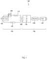
- FIG. 1is an example transformer resonant converter according to some embodiments.
- FIG. 2is a circuit diagram of an example transformer resonant converter coupled with switching circuitry and a load according to some embodiments.
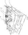
- FIG. 3is a photograph of an example resonant converter.
- FIG. 4is an example waveform created from a transformer resonant converter according to some embodiments.
- FIG. 5is an example waveform created from a transformer resonant converter according to some embodiments.
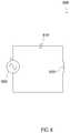
- FIG. 6is an idealized example of a series resonant circuit according to some embodiments.
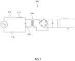
- FIG. 7is a circuit diagram of an example transformer resonant converter according to some embodiments.
- the switching voltage sourcemay include a full bridge or a half bridge topology.
- the switching voltage sourcemay include a full bridge or a half bridge switch topology.
- the switching voltage sourcemay have additional output filter elements.
- the switching voltage sourcefor example, may include a full bridge topology or a half bridge topology.
- the switching voltage sourcemay include a switching power amplifier.
- the transformer resonant convertermay not include any physical capacitors and/or inductors. Instead, in some embodiments, the transformer resonant converter may include a resistor in series with the stray capacitance and/or the stray inductance of at least the transformer.
- the stray inductance, L so , and/or stray capacitance, C so , of other circuit elementsmay also be leveraged as part of the resonant converter.
- the total stray inductance and/or the stray capacitancecan be small. For example, the stray inductance can be less than about 3,000 nH, 300 nH, 30 nH, 3 nH etc., as measured on the primary side of the transformer.
- the stray capacitancecan be less than about 300 pF or less than about 30 pF, as measured on the secondary side of the transformer. Additional capacitance, C a , and inductance, L a , may be added in conjunction such as, for example, in parallel and/or series with the stray capacitance and stray inductance.
- Resonant converterstypically leverage the resonance of a circuit when the circuit is driven at the resonant frequency (an example series resonant circuit is shown in FIG. 6 ).
- the resonant frequencycan be determined from the total inductance and capacitance of the circuit elements, for example, from the following:
- FIG. 6shows an idealized series resonant circuit 600 without any resistance; and with an inductor 620 , a capacitor 610 , and power source 605 . Resistance may be present in various forms throughout the circuit.
- the effective reactance of each of the circuit componentsare equal in magnitude but opposite in sign. Therefore, they cancel each other out and all that's left is the real resistance of the circuit whether composed of stray resistance and/or resistive elements, including the load.
- this real resistancecan be the resistance of the copper traces and/or any other circuit components in series with the resonant LC components.
- the ratio of the reactive components to the real resistanceis defined as the Q factor, which is a dimensionless parameter that is a good estimate for what multiplier the driving voltage will ring up to when measured across either L or C.
- the resonant frequency and Q factorcan be calculated from the following:
- Ris the total equivalent series/dissipative resistance and may include any series stray resistance Rs as well as any additionally added resistance Ra, and additional equivalent series load resistance R L , as well as any other dielectric or other dissipative losses from switches or other components.
- Typical resonant convertersuse discrete physical circuit components for the inductor, capacitor, and/or a resistor to create a desired Q factor and resonant frequency f.
- additional resistancemay be left out to improve circuit efficiency.
- some form of feedback and controlmay be used to regulate the output voltage to a value lower than that which would naturally be set by the circuit Q.
- One such form of feedback and controlmay rely on pulse width modulation of the switching voltage source.
- FIG. 1is a circuit diagram of an example transformer resonant converter 100 according to some embodiments.
- the resonant converter 100may include, for example, a DC input 105 coupled with a switch 110 .
- the switchmay include a freewheeling diode or a body diode.
- the switch 110may open and close at high frequencies, such as, for example, at the resonant frequency of the transformer resonant converter 100 .
- the switch 110may be any type of solid-state switch.
- the primary side 160 of the resonant convertermay also include resonant series inductance 115 and resonant series resistance 120 .
- the switch 110can produce high frequency pulses such as at frequencies greater than 50 KHz, 500 kHz, 5000 KHz, for example.
- the switch 110may operate with transition times less than, for example, about 40 ns, 10 ns, or 1 ns.
- the switch 110may include a solid-state switch.
- the switch 110may include an IGBT switch, MOSFET switch, FET switch, GaN switch, etc.
- the switch 110may be a high efficiency switch.
- the switch 110may be a fast switch (e.g., switching with a frequency greater than 100 kHz), which may allow for an output with low ripple.
- pulse width modulation (PWM) techniquescan be utilized for fast control of the output voltage, to allow, for example, the control of beam characteristics with tens of ⁇ s resolution, for example, when driving neutral beams.
- PWMpulse width modulation
- the resonant series inductance 115may include, for example, stray inductance of the transformer, stray inductance of the primary side 160 circuitry, and/or a physical inductor.
- the resonant series inductance 115may be small, for example, less than about 3,000 nH, 300 nH, 30 nH, 3 nH, etc.
- the resonant series resistance 120may include stray resistance and/or a physical resistor.
- a physical resistormay lower circuit efficiency, however, a physical resistor may allow for faster circuit response times, and/or may reduce the need for feedback and control loops to control/regulate the output voltage.
- the transformer 125may include any type of transformer such as, for example, a toroid shaped transformer with one or more primary side windings and a plurality of secondary side windings.
- the transformer 125may be a coaxial transformer with one or more primary side windings and a plurality of secondary side windings.
- the one or more primary side windingsmay include a conductive sheet.
- the one or more secondary windingsmay include a conductive sheet.
- the circuitry on the secondary side of the transformer 125may include resonant series capacitance 130 .
- the resonant series capacitance 130may include stray capacitance of the transformer and/or stray capacitance of the secondary side circuitry and/or a capacitor.
- the resonant series capacitance 130may be small, for example, less than about 1,000 pF, 100 pF, 10 pF, etc.
- the resonant series capacitance 130may be in parallel with the transformer output.
- the secondary side 165 of the circuitmay include a rectifier 135 and/or an output filter 140 .
- a primary winding and/or a secondary windingmay include single conductive sheet that is wrapped around at least a portion of a transformer core.
- a conductive sheetmay wrap around the outside, top, and inside surfaces of a transformer core.
- Conductive traces and/or planes on and/or within the circuit boardmay complete the primary turn, and/or connect the primary turn to other circuit elements.
- the conductive sheetmay comprise a metal sheet.
- the conductive sheetmay comprise sections of pipe, tube, and/or other thin walled metal objects that have a certain geometry.
- a conductive sheetmay terminate on one or more pads on a circuit board. In some embodiments, a conductive sheet may terminate with two or more wires.
- a primary windingmay include a conductive paint that has been painted on one or more outside surfaces of the transformer core.
- the conductive sheetmay include a metallic layer that has been deposited on the transformer core using a deposition technique such as thermal spray coating, vapor deposition, chemical vapor deposition, ion beam deposition, plasma and thermal spray deposition, etc.
- the conductive sheetmay comprise a conductive tape material that is wrapped around the transformer core.
- the conductive sheetmay comprise a conductor that has been electroplated on the transformer core.
- a plurality of wires in parallelcan be used in place of the conductive sheet.
- an insulatormay be disposed or deposited between transformer core and the conductive sheet.
- the insulatormay include a polymer, a polyimide, epoxy, etc.
- the rectifier 135may include any type of rectifier such as, for example, a diode-based rectifier, a full-bridge rectifier (e.g., as shown in FIG. 7 ), a half-bridge rectifier, a three-phase rectifier, a voltage multiplying rectifier, etc. Any other type of rectifier can be used.
- a diode-based rectifiere.g., as shown in FIG. 7
- a half-bridge rectifiere.g., as shown in FIG. 7
- Any other type of rectifiercan be used.
- the output filter 140may include any type of filter.
- the output filter 140may include a high pass filter, a low pass filter, a band pass filter, etc.
- Some embodimentsmay include a transformer resonant converter 100 that has low stray inductance measured from the primary side 160 .
- Low stray inductancemay include inductance less than, for example, about 3,000 nH, 300 nH, 30 nH, 3 nH, etc.
- Some embodimentsmay include a transformer resonant converter 100 that has low stray capacitance as measured from the primary side 160 .
- Low stray capacitancemay include capacitance less than, for example, about 1,000 pF, 100 pF, 10 pF, etc.
- Some embodimentsmay include the transformer resonant converter 100 that can produce high average output power such as greater than, for example, about 3 kW, 100 kW, 3 MW. For short bursts the peak power output, for example, may exceed 30 kW, 300 kW, 3 MW. Some embodiments may include a transformer resonant converter 100 that produces pulses with high voltage such as greater than, for example, 5 kV, 25 kV, 250 kV, 2500 kV. Some embodiments may include a transformer resonant converter 100 that produces a high power burst operation with a peak power greater than 5 times the average operating power of the converter. In some embodiments, the peak power output may be in excess of the average output power by a factor, for example, of 5 , 50 , 500 .
- the transformer resonant converter 100can produce high voltage pulses with a fast rise time, for example, less than, for example, about 10 ⁇ s, 1 ⁇ s, 100 ns, 10 ns, etc. for voltages greater than for example 5 kV, 30 kV, 100 kV, 500 kV, etc.
- the transformer resonant converter 100can produce an output pulse with low voltage ripple such as, for example, less than about 5%. Typical output voltage ripple may be less than, for example, 15% or 0.5%.
- the transformer resonant converter 100can operate with pulse width modulation that may allow for greater control of the output waveform and/or allow for high efficiency power output.
- the transformer resonant convertermay include real time feedback and control of the high voltage and/or power output.
- the low stray inductance and/or low stray capacitance, and/or high frequency of operationcan allow for this feedback loop to be fast.
- the transformer resonant converter 100may significantly increase the overall power density of a system.
- the transformer resonant converter 100could be used with an electron tube driver for high-power radar systems and/or RF systems.
- the transformer resonant converter 100may increase the overall power density of the high-power radar systems and/or the RF systems. Power densities may exceed, for example, 0.5 W/cm 3 , 5 W/cm 3 , 50 W/cm 3 , or 500 W/cm 3 .
- the transformer resonant converter 100may include switching components that are at low voltage in a standard H-bridge power supply configuration with a hard ground reference. This may, for example, remove the requirement of floating each module to high voltage as seen in the pulse step modulator.
- a transformer resonant convertermay include high voltage components that include a high voltage transformer and rectification diodes and other high voltage components. These components can, for example, be packaged for safe high voltage using oil, potting or other methods. In some embodiments, some components may be in air with appropriate stand-off to eliminate corona generation, arcing, and/or tracking.
- the outputis transformer isolated, so the same system can provide either a floating or ground referenced output and/or can be configured to provide either a positive or negative polarity.
- Thismay allow, for example, the same design to be utilized for any of the various high voltage grids of a particular neutral beam injection design including, for example, either positive or negative ion extraction and acceleration as well as ion and electron suppressor grids.
- a resonant convertermay produce the same power levels with a dramatic decrease in overall system size and/or control complexity as compared to the pulse step modulators used currently for smaller neutral beam injector systems.
- the resonant convertermay be safe to arc-faults due the inherent series resonant behavior of the supply.
- the series resonant behavior of a resonant convertermay have a supply impedance that is matched to the load. When an arc occurs, for example, this mismatch can reduce the power flowing in the primary side 160 of the circuit and the voltage on the secondary may fall, whereby the current in the arc cannot continue to increase to the point of damage to the grids.
- the transformer resonant convertermay have very little energy stored in its output filter components.
- this stored energymay be less than, for example, about 10 J, 1.0 J, or 0.1 J.
- the high frequency of operationallows this stored energy to be minimized. In some embodiments, minimizing this stored energy can be important. This energy, for example, can damage load components when arcs occur.
- a transformer resonant convertermay be modular.
- a transformer resonant convertermay be easily scaled to higher output power levels making it a possible choice for large neutral beam injector systems such as, for example, like those used at NSTX, DIII-D, or ITER.
- power supplies with a transformer resonant convertercan be added together with output arranged in series to easily increase the output voltage.
- output currentcan be increased by adding units in parallel on the primary as long as the high voltage side is scaled to account for the increase current level.
- FIG. 2is a circuit diagram of a transformer resonant converter 200 coupled with a load 250 according to some embodiments.
- the transformer 225can have any number of turns.
- the total series inductanceis represented by an inductor circuit element 205 (e.g., having an inductance less than about 3,000 nH, 300 nH, 30 nH, 3 nH) on the primary side 260 , which may be primarily composed of the stray inductance L s of the transformer.
- the total series capacitanceis represented by a capacitor circuit element 210 (e.g., having a capacitance less than about 1,000 pF, 100 pF, 10 pF, etc.) on the secondary side 265 , which may be primarily composed of the stray capacitance C s of the transformer.
- the stray inductance 205 and/or the stray capacitance 210can be of any value depending on the size, type, material, etc. of the transformer and/or the number of turns of the transformer.
- a primary resistor 215may be included in the circuit in series with the inductor 205 and/or the capacitor 210 .
- the primary resistor 215may have a small value, such as, for example, less than 3,000 mOhms, 300 mOhms, 30 mOhms, 3 mOhms.
- the transformer resonant converter 200includes switching circuitry with four switch circuits 230 .
- Each switch circuit 230may include a solid-state switch 235 with any number of circuit elements.
- the solid-state switchmay include, for example, an IGBT switch, MOSFET switch, FET switch, GaN switch, etc.
- Each switch circuit 230may also include stray inductance represented by circuit element 240 and/or stray resistance represented by circuit element 245 .
- Each switch circuit 230may also include a diode 255 .
- the secondary side of the transfermay also include a full bridge rectifier 261 , an output filter 270 , a load element 250 (e.g., in a specific example, comprising an 86 k Ohm resistor), and/or a filter resistor 280 (e.g., in a specific example, comprising a 10 k Ohm resistor) that acts in conjunction with an external user load capacitor 285 (e.g., in a specific example, comprising a capacitor of 30 pF).
- a full bridge rectifier 261e.g., an output filter 270 , a load element 250 (e.g., in a specific example, comprising an 86 k Ohm resistor), and/or a filter resistor 280 (e.g., in a specific example, comprising a 10 k Ohm resistor) that acts in conjunction with an external user load capacitor 285 (e.g., in a specific example, comprising a capacitor of 30 pF).
- no feedback and control regulationmay be
- circuit elementsmay follow the rectifier.
- these other elementsmay include capacitive, inductive, and/or resistive filter components, and/or the external loads.
- a transformer resonant converter(e.g., transformer resonant converter 100 , transformer resonant converter 200 , transformer resonant converter 700 , etc.) can produce pulses with various properties.
- a transformer resonant convertercan produce pulses with a voltage greater than about 30 kV.
- a transformer resonant convertercan produce pulses with a voltage greater than about 5 kV, 25 kV, 250 kV, or 2,500 kV.
- a transformer resonant convertercan produce pulses with a rise time to or a fall time from voltages greater than about 25 kV of less than about 300 ⁇ s, 30 ⁇ s, 3 ⁇ s.
- a transformer resonant convertercan produce pulses with a variable pulse width.
- a transformer resonant convertercan produce pulses with a variable frequency.
- a transformer resonant convertercan produce pulses with a variable voltage.
- a transformer resonant convertercan produce pulses for a dielectric barrier discharge and/or neutral beam injection devices.
- a transformer resonant convertercan produce pulses that have a pulse width of any duration such as, for example, ranging from about 1 ⁇ s to DC.
- a transformer resonant convertercan produce pulses with a pulse repetition rate greater than about 1 kHz for continuous operation at average power levels in excess of several kilowatts.
- a transformer resonant convertercan produce pulses having a pulse repetition frequency greater than about 1 kHz, 30 kHz, or 1000 kHz.
- a transformer resonant convertercan produce pulses having power greater than about 3 kW, 100 kW, or 3 MW.
- a transformer resonant convertercan be housed in a rack-mountable enclosure (e.g., standard 6U enclosure that is has approximate dimensions of 10′′ ⁇ 17′′ ⁇ 28′′).
- a transformer resonant convertermay have a high power density, for example, a power density that can exceed 0.5 W/cm 3 , 5 W/cm 3 , 50 W/cm 3 or 500 W/cm 3 .
- a transformer resonant convertermay include any type of solid state switches such as, for example, an IGBT, an FET, a MOSFET, a SiC junction transistor, a GaN switch, etc.
- FIG. 3is a photograph of an example transformer resonant converter including a transformer with windings 310 and a plurality of resistors 305 .
- the value of the cumulative resistance of the plurality of resistors 305can be determined from equation 2 for a give Q factor.
- the transformer resonant converteralso includes a plurality of solid state switches 315 that are coupled with heat sinks. The solid-state switches can be arranged, for example, in the full bridge topology in this instance.
- the transformer resonant converteralso includes a plurality of full-bridge rectifying diodes 320 . Numerous other circuit elements can also be included.
- FIG. 4is an example waveform created from a transformer resonant converter according to some embodiments.
- the output voltageis greater than 30 kV, has a rise time of about 4 ⁇ s and a flat top width of about 12 ⁇ s.
- FIG. 5is another example waveform created from a transformer resonant converter according to some embodiments.
- This waveformwas produced by the switching resonant converter shown in FIG. 2 .
- the input voltage to the transformer resonant converterwas 600 V and the output pulse is 30 kV.
- the rise timeis about 5 ⁇ s and the flat top width is about 20 ⁇ s.
- These waveformscould have additional rises, flat tops, and falls, depending on the modulation of the resonant converter.
- This waveformshows one typical output pulse; various other output pulses are possible.
- the high power density, power, frequency, rise time, and/or voltage of the output of a transformer resonant convertercan be unique.
- These attributesmay be enabled by the use of a transformer (and/or circuit) with low stray capacitance and/or low stray inductance that allows for operation at high frequency, and the use of solid state switches that operate at high power with very fast transition times.
- FIG. 7is a circuit diagram of an example transformer resonant converter 700 according to some embodiments.
- a transformer 705is coupled with and/or is part of a resonant converter topology where the transformer 705 has a step-up voltage of n, which represents the ratio of turns of the primary winding to the turns of the secondary winding of the transformer 705 .
- the stray inductance L sis represented by inductor 715
- the stray capacitance C sis represented by capacitor 720 of the transformer.
- the stray inductance L so and stray capacitance c so of other circuit elementscan also be leveraged be used in conjunction with stray inductance L s 715 and capacitance C s 720 to achieve the desired resonant frequency f, and Q.
- Resistor 710represents the additional resistance R a that may be included on the primary side of the transformer.
- the voltage on the secondary of the transformercan be stepped up by the transformer by a factor of n multiplied by the resonant converter by a factor of Q.
- the total stray inductance and the total stray capacitance, of the transformer and/or other circuit elementsare kept low, for example, to produce a resonant oscillating voltage at high frequency, and an output voltage with fast rise times and/or fast fall rise times.
- the circuitcan switch at high frequencies such as, for example, at frequencies greater than 50 kHz, 500 kHz, 5 MHz, for example.
- the low total stray inductance and the low total stray capacitance of the transformer and/or other circuit elementsmay also, for example, be kept low to produce fast rectified rise times, faster than 100 ⁇ s, 10 ⁇ s, 1 ⁇ s, for example.
- the stray capacitancecan be measured from the secondary side of the transformer.
- the stray capacitancecan be measured from the primary side of the transformer, which is equal to the capacitance on the secondary side of the transformer times the square of the turns ratio n.
- the stray inductancecan be measured from the primary side of the transformer.
- the stray inductancecan be measured from the secondary side of the transformer, which is equal to the inductance on the primary side of the transformer times the square of the turns ratio n.
- the total equivalent series capacitancecan be measured from the secondary side of the transformer.
- the total equivalent series capacitancecan be measured from the primary side of the transformer, which is equal to the total equivalent series capacitance on the secondary side of the transformer times the square of the turns ratio n.
- the total equivalent series inductancecan be measured from the primary side of the transformer.
- the total equivalent series inductancecan be measured from the secondary side of the transformer, which is equal to the total equivalent series inductance on the primary side of the transformer times the square of the turns ratio n.
Landscapes
- Engineering & Computer Science (AREA)
- Power Engineering (AREA)
- Physics & Mathematics (AREA)
- Computer Networks & Wireless Communication (AREA)
- General Physics & Mathematics (AREA)
- Radar, Positioning & Navigation (AREA)
- Remote Sensing (AREA)
- Plasma & Fusion (AREA)
- Chemical & Material Sciences (AREA)
- Analytical Chemistry (AREA)
- Dc-Dc Converters (AREA)
- Electronic Switches (AREA)
Abstract
Description
and the resonant converter produces an output voltage Voutfrom an input voltage Vin, according to Vout=QnVin. In some embodiments, the stray inductance is measured from the primary side of the transformer and the stray capacitance is measured from the secondary side. In some embodiments, additional capacitance, Ca, and/or inductance, La, may be included to produce a desired resonant frequency and/or change the circuit Q.
where R is the sum of the series stray resistance Rsand any additionally added resistance Raand equivalent series load resistance RL, C is the sum of the stray capacitance Csand any added capacitance Caand any other stray capacitance Cso, and L is the sum of the stray series inductance Lsand any additional added inductance Laand any other stray series inductance Lso.
in this example, L and C represent the total effective and/or equivalent series circuit inductance and capacitance, respectively, and as defined above, L=Ls+Lso+La, and C=Cs+Cso+Ca.
R is the total equivalent series/dissipative resistance and may include any series stray resistance Rs as well as any additionally added resistance Ra, and additional equivalent series load resistance RL, as well as any other dielectric or other dissipative losses from switches or other components. Typical resonant converters use discrete physical circuit components for the inductor, capacitor, and/or a resistor to create a desired Q factor and resonant frequency f. In some embodiments, additional resistance may be left out to improve circuit efficiency. In some embodiments, some form of feedback and control may be used to regulate the output voltage to a value lower than that which would naturally be set by the circuit Q. One such form of feedback and control, for example, may rely on pulse width modulation of the switching voltage source.
Vout=QnVc (3).
Thus, the voltage on the secondary of the transformer can be stepped up by the transformer by a factor of n multiplied by the resonant converter by a factor of Q.
Claims (22)
Priority Applications (3)
| Application Number | Priority Date | Filing Date | Title |
|---|---|---|---|
| US15/889,586US11171568B2 (en) | 2017-02-07 | 2018-02-06 | Transformer resonant converter |
| US17/163,331US11539352B2 (en) | 2013-11-14 | 2021-01-29 | Transformer resonant converter |
| US18/053,249US20230093824A1 (en) | 2013-11-14 | 2022-11-07 | Transformer resonant converter |
Applications Claiming Priority (2)
| Application Number | Priority Date | Filing Date | Title |
|---|---|---|---|
| US201762456060P | 2017-02-07 | 2017-02-07 | |
| US15/889,586US11171568B2 (en) | 2017-02-07 | 2018-02-06 | Transformer resonant converter |
Related Parent Applications (1)
| Application Number | Title | Priority Date | Filing Date |
|---|---|---|---|
| US16/457,791Continuation-In-PartUS10985740B2 (en) | 2013-11-14 | 2019-06-28 | High voltage nanosecond pulser with variable pulse width and pulse repetition frequency |
Related Child Applications (1)
| Application Number | Title | Priority Date | Filing Date |
|---|---|---|---|
| US17/163,331Continuation-In-PartUS11539352B2 (en) | 2013-11-14 | 2021-01-29 | Transformer resonant converter |
Publications (2)
| Publication Number | Publication Date |
|---|---|
| US20180226896A1 US20180226896A1 (en) | 2018-08-09 |
| US11171568B2true US11171568B2 (en) | 2021-11-09 |
Family
ID=63038884
Family Applications (1)
| Application Number | Title | Priority Date | Filing Date |
|---|---|---|---|
| US15/889,586ActiveUS11171568B2 (en) | 2013-11-14 | 2018-02-06 | Transformer resonant converter |
Country Status (4)
| Country | Link |
|---|---|
| US (1) | US11171568B2 (en) |
| EP (2) | EP4266579A3 (en) |
| CN (2) | CN110692188B (en) |
| WO (1) | WO2018148182A1 (en) |
Cited By (7)
| Publication number | Priority date | Publication date | Assignee | Title |
|---|---|---|---|---|
| US11631573B2 (en) | 2014-02-28 | 2023-04-18 | Eagle Harbor Technologies, Inc. | High voltage resistive output stage circuit |
| US11646176B2 (en) | 2019-01-08 | 2023-05-09 | Eagle Harbor Technologies, Inc. | Efficient nanosecond pulser with source and sink capability for plasma control applications |
| US11875971B2 (en) | 2018-07-27 | 2024-01-16 | Eagle Harbor Technologies, Inc. | Efficient energy recovery in a nanosecond pulser circuit |
| US12230477B2 (en) | 2018-07-27 | 2025-02-18 | Eagle Harbor Technologies, Inc. | Nanosecond pulser ADC system |
| US12348228B2 (en) | 2022-06-29 | 2025-07-01 | EHT Ventures LLC | Bipolar high voltage pulser |
| US12354832B2 (en) | 2022-09-29 | 2025-07-08 | Eagle Harbor Technologies, Inc. | High voltage plasma control |
| US12437967B2 (en) | 2020-07-09 | 2025-10-07 | Eagle Harbor Technologies, Inc. | Ion current droop compensation |
Families Citing this family (42)
| Publication number | Priority date | Publication date | Assignee | Title |
|---|---|---|---|---|
| US10892140B2 (en) | 2018-07-27 | 2021-01-12 | Eagle Harbor Technologies, Inc. | Nanosecond pulser bias compensation |
| US10978955B2 (en) | 2014-02-28 | 2021-04-13 | Eagle Harbor Technologies, Inc. | Nanosecond pulser bias compensation |
| US11171568B2 (en) | 2017-02-07 | 2021-11-09 | Eagle Harbor Technologies, Inc. | Transformer resonant converter |
| US11539352B2 (en) | 2013-11-14 | 2022-12-27 | Eagle Harbor Technologies, Inc. | Transformer resonant converter |
| US10020800B2 (en) | 2013-11-14 | 2018-07-10 | Eagle Harbor Technologies, Inc. | High voltage nanosecond pulser with variable pulse width and pulse repetition frequency |
| EP4210223A1 (en) | 2013-11-14 | 2023-07-12 | Eagle Harbor Technologies, Inc. | High voltage nanosecond pulser |
| US11004660B2 (en) | 2018-11-30 | 2021-05-11 | Eagle Harbor Technologies, Inc. | Variable output impedance RF generator |
| US11824454B2 (en)* | 2016-06-21 | 2023-11-21 | Eagle Harbor Technologies, Inc. | Wafer biasing in a plasma chamber |
| US11430635B2 (en) | 2018-07-27 | 2022-08-30 | Eagle Harbor Technologies, Inc. | Precise plasma control system |
| US10333410B2 (en)* | 2016-09-15 | 2019-06-25 | Futurewei Technologies, Inc. | Common-mode (CM) electromagnetic interference (EMI) reduction in resonant converters |
| JP6902167B2 (en) | 2017-08-25 | 2021-07-14 | イーグル ハーバー テクノロジーズ, インク.Eagle Harbor Technologies, Inc. | Generation of arbitrary waveforms using nanosecond pulses |
| US10510575B2 (en) | 2017-09-20 | 2019-12-17 | Applied Materials, Inc. | Substrate support with multiple embedded electrodes |
| US10555412B2 (en) | 2018-05-10 | 2020-02-04 | Applied Materials, Inc. | Method of controlling ion energy distribution using a pulse generator with a current-return output stage |
| US11381071B2 (en)* | 2018-07-17 | 2022-07-05 | Hubbell Incorporated | Voltage harvester for power distribution system devices |
| US11532457B2 (en) | 2018-07-27 | 2022-12-20 | Eagle Harbor Technologies, Inc. | Precise plasma control system |
| US11222767B2 (en) | 2018-07-27 | 2022-01-11 | Eagle Harbor Technologies, Inc. | Nanosecond pulser bias compensation |
| US10607814B2 (en)* | 2018-08-10 | 2020-03-31 | Eagle Harbor Technologies, Inc. | High voltage switch with isolated power |
| JP7038901B2 (en) | 2018-08-10 | 2022-03-18 | イーグル ハーバー テクノロジーズ,インク. | Plasma sheath control for RF plasma reactor |
| US11476145B2 (en) | 2018-11-20 | 2022-10-18 | Applied Materials, Inc. | Automatic ESC bias compensation when using pulsed DC bias |
| KR102827481B1 (en) | 2019-01-22 | 2025-06-30 | 어플라이드 머티어리얼스, 인코포레이티드 | Feedback loop to control pulse voltage waveform |
| US11508554B2 (en) | 2019-01-24 | 2022-11-22 | Applied Materials, Inc. | High voltage filter assembly |
| WO2020243023A1 (en)* | 2019-05-24 | 2020-12-03 | Eagle Harbor Technologies, Inc. | Klystron driver |
| TWI778449B (en) | 2019-11-15 | 2022-09-21 | 美商鷹港科技股份有限公司 | High voltage pulsing circuit |
| US11532989B2 (en) | 2019-11-27 | 2022-12-20 | Hamilton Sundstrand Corporation | Using parasitic capacitance of a transformer as a tank element in a DC-DC converter |
| EP4082036B1 (en) | 2019-12-24 | 2025-01-22 | Eagle Harbor Technologies, Inc. | Nanosecond pulser rf isolation for plasma systems |
| US11848176B2 (en) | 2020-07-31 | 2023-12-19 | Applied Materials, Inc. | Plasma processing using pulsed-voltage and radio-frequency power |
| US11798790B2 (en) | 2020-11-16 | 2023-10-24 | Applied Materials, Inc. | Apparatus and methods for controlling ion energy distribution |
| US11901157B2 (en) | 2020-11-16 | 2024-02-13 | Applied Materials, Inc. | Apparatus and methods for controlling ion energy distribution |
| US11495470B1 (en) | 2021-04-16 | 2022-11-08 | Applied Materials, Inc. | Method of enhancing etching selectivity using a pulsed plasma |
| US11948780B2 (en) | 2021-05-12 | 2024-04-02 | Applied Materials, Inc. | Automatic electrostatic chuck bias compensation during plasma processing |
| US11791138B2 (en) | 2021-05-12 | 2023-10-17 | Applied Materials, Inc. | Automatic electrostatic chuck bias compensation during plasma processing |
| US11967483B2 (en) | 2021-06-02 | 2024-04-23 | Applied Materials, Inc. | Plasma excitation with ion energy control |
| US12394596B2 (en) | 2021-06-09 | 2025-08-19 | Applied Materials, Inc. | Plasma uniformity control in pulsed DC plasma chamber |
| US20220399185A1 (en) | 2021-06-09 | 2022-12-15 | Applied Materials, Inc. | Plasma chamber and chamber component cleaning methods |
| US11810760B2 (en) | 2021-06-16 | 2023-11-07 | Applied Materials, Inc. | Apparatus and method of ion current compensation |
| US11569066B2 (en) | 2021-06-23 | 2023-01-31 | Applied Materials, Inc. | Pulsed voltage source for plasma processing applications |
| US11476090B1 (en) | 2021-08-24 | 2022-10-18 | Applied Materials, Inc. | Voltage pulse time-domain multiplexing |
| US12106938B2 (en) | 2021-09-14 | 2024-10-01 | Applied Materials, Inc. | Distortion current mitigation in a radio frequency plasma processing chamber |
| US11972924B2 (en) | 2022-06-08 | 2024-04-30 | Applied Materials, Inc. | Pulsed voltage source for plasma processing applications |
| US12315732B2 (en) | 2022-06-10 | 2025-05-27 | Applied Materials, Inc. | Method and apparatus for etching a semiconductor substrate in a plasma etch chamber |
| US12272524B2 (en) | 2022-09-19 | 2025-04-08 | Applied Materials, Inc. | Wideband variable impedance load for high volume manufacturing qualification and on-site diagnostics |
| US12111341B2 (en) | 2022-10-05 | 2024-10-08 | Applied Materials, Inc. | In-situ electric field detection method and apparatus |
Citations (182)
| Publication number | Priority date | Publication date | Assignee | Title |
|---|---|---|---|---|
| US4070589A (en) | 1976-10-29 | 1978-01-24 | The Singer Company | High speed-high voltage switching with low power consumption |
| US4438331A (en) | 1981-12-02 | 1984-03-20 | Power Spectra, Inc. | Bulk semiconductor switch |
| US4504895A (en) | 1982-11-03 | 1985-03-12 | General Electric Company | Regulated dc-dc converter using a resonating transformer |
| EP0174164A2 (en) | 1984-09-01 | 1986-03-12 | GEC-Marconi Limited | A pulse generator |
| US4885074A (en) | 1987-02-24 | 1989-12-05 | International Business Machines Corporation | Plasma reactor having segmented electrodes |
| US4924191A (en) | 1989-04-18 | 1990-05-08 | Erbtec Engineering, Inc. | Amplifier having digital bias control apparatus |
| US4992919A (en) | 1989-12-29 | 1991-02-12 | Lee Chu Quon | Parallel resonant converter with zero voltage switching |
| US5072191A (en) | 1989-03-30 | 1991-12-10 | Hitachi Metals, Ltd. | High-voltage pulse generating circuit, and discharge-excited laser and accelerator containing such circuit |
| US5118969A (en) | 1990-02-09 | 1992-06-02 | General Atomics | Multiple pulse generator using saturable inductor |
| US5140510A (en) | 1991-03-04 | 1992-08-18 | Motorola, Inc. | Constant frequency power converter |
| US5313481A (en) | 1993-09-29 | 1994-05-17 | The United States Of America As Represented By The United States Department Of Energy | Copper laser modulator driving assembly including a magnetic compression laser |
| US5321597A (en) | 1991-03-22 | 1994-06-14 | Gec Alsthom Sa | Galvanic isolation device for direct current electrical signals or electrical signals likely to include a direct current component |
| US5325021A (en) | 1992-04-09 | 1994-06-28 | Clemson University | Radio-frequency powered glow discharge device and method with high voltage interface |
| US5392043A (en) | 1993-10-04 | 1995-02-21 | General Electric Company | Double-rate sampled signal integrator |
| US5451846A (en) | 1993-12-14 | 1995-09-19 | Aeg Automation Systems Corporation | Low current compensation control for thyristor armature power supply |
| US5488552A (en) | 1992-10-07 | 1996-01-30 | Hiroshi Sakamoto | Inverter power supply |
| US5610452A (en) | 1992-04-13 | 1997-03-11 | The United States Of America As Represented By The United States Department Of Energy | E-beam high voltage switching power supply |
| US5623171A (en) | 1989-09-14 | 1997-04-22 | Hitachi Metals, Ltd. | High-voltage pulse generating circuit and electrostatic recipitator containing it |
| JPH09129621A (en) | 1995-09-28 | 1997-05-16 | Applied Materials Inc | Pulse waveform bias power |
| US5656123A (en) | 1995-06-07 | 1997-08-12 | Varian Associates, Inc. | Dual-frequency capacitively-coupled plasma reactor for materials processing |
| US5729562A (en) | 1995-02-17 | 1998-03-17 | Cymer, Inc. | Pulse power generating circuit with energy recovery |
| US5796598A (en) | 1996-01-26 | 1998-08-18 | W. Schlafhorst Ag & Co. | Voltage-converting circuit for the power supply of an electrical consumer of high output, particularly a bobbin winding machine |
| US5808504A (en) | 1995-08-25 | 1998-09-15 | Mitsubishi Denki Kabushiki Kaisha | Insulated gate transistor drive circuit |
| US5905646A (en) | 1996-12-20 | 1999-05-18 | Scanditronix Medical Ab | Power modulator |
| US5930125A (en) | 1996-08-28 | 1999-07-27 | Siemens Medical Systems, Inc. | Compact solid state klystron power supply |
| EP0947048A1 (en) | 1996-12-20 | 1999-10-06 | Scanditronix Medical AB | Power modulator |
| US5968377A (en) | 1996-05-24 | 1999-10-19 | Sekisui Chemical Co., Ltd. | Treatment method in glow-discharge plasma and apparatus thereof |
| CA2292526A1 (en) | 1998-06-03 | 1999-12-09 | Neurocontrol Corporation | Percutaneous intramuscular stimulation system |
| US6059935A (en) | 1995-06-19 | 2000-05-09 | The University Of Tennessee Research Corporation | Discharge method and apparatus for generating plasmas |
| US6066901A (en) | 1998-09-17 | 2000-05-23 | First Point Scientific, Inc. | Modulator for generating high voltage pulses |
| US6087871A (en) | 1995-11-15 | 2000-07-11 | Kardo-Syssoev; Alexei F. | Pulse generating circuits using drift step recovery devices |
| US6205074B1 (en) | 2000-02-29 | 2001-03-20 | Advanced Micro Devices, Inc. | Temperature-compensated bias generator |
| US6233161B1 (en) | 2000-03-02 | 2001-05-15 | Power Integrations, Inc. | Switched mode power supply responsive to voltage across energy transfer element |
| US6238387B1 (en) | 1996-08-23 | 2001-05-29 | Team Medical, L.L.C. | Electrosurgical generator |
| US6253704B1 (en) | 1995-10-13 | 2001-07-03 | Mattson Technology, Inc. | Apparatus and method for pulsed plasma processing of a semiconductor substrate |
| US20010008552A1 (en) | 2000-01-17 | 2001-07-19 | Toyoshige Harada | X-ray computer tomography apparatus |
| EP1128557A2 (en) | 2000-02-21 | 2001-08-29 | Ngk Insulators, Ltd. | Switching circuit for generating pulsed power |
| WO2001093419A1 (en) | 2000-05-30 | 2001-12-06 | Bumjong Ko | Output stage protection circuit for power amplifier |
| US20020016617A1 (en) | 1996-06-13 | 2002-02-07 | Oldham Jacqueline A. | Stimulation of muscles |
| US6359542B1 (en) | 2000-08-25 | 2002-03-19 | Motorola, Inc. | Securement for transformer core utilized in a transformer power supply module and method to assemble same |
| US6362604B1 (en) | 1998-09-28 | 2002-03-26 | Alpha-Omega Power Technologies, L.L.C. | Electrostatic precipitator slow pulse generating circuit |
| US6392187B1 (en) | 1997-10-15 | 2002-05-21 | Tokyo Electron Limited | Apparatus and method for utilizing a plasma density gradient to produce a flow of particles |
| US20020140464A1 (en) | 2000-05-03 | 2002-10-03 | Joseph Yampolsky | Repetitive power pulse generator with fast rising pulse |
| US6480399B2 (en) | 2000-03-02 | 2002-11-12 | Power Integrations, Inc. | Switched mode power supply responsive to current derived from voltage across energy transfer element input |
| US6483731B1 (en) | 2000-07-31 | 2002-11-19 | Vanner, Inc. | Alexander topology resonance energy conversion and inversion circuit utilizing a series capacitance multi-voltage resonance section |
| US20020180276A1 (en) | 2001-05-31 | 2002-12-05 | Ngk Insulators, Ltd. | Circuit for generating high voltage pulse |
| US20020186577A1 (en) | 2001-06-06 | 2002-12-12 | Siemens Medical Systems, Inc. | Unified power architecture |
| US6496047B1 (en) | 1998-06-23 | 2002-12-17 | Eev Liimited | Solid state switch with pulsed control |
| US20030021125A1 (en) | 2001-07-16 | 2003-01-30 | Alfred-Christophe Rufer | Electrical power supply suitable in particular for DC plasma processing |
| US20030071035A1 (en) | 2001-10-16 | 2003-04-17 | Brailove Adam Alexander | Induction plasma reactor |
| US6577135B1 (en) | 1992-07-08 | 2003-06-10 | Texas Instruments Incorporated | Battery pack with monitoring function utilizing association with a battery charging system |
| US20030137791A1 (en) | 2002-01-18 | 2003-07-24 | Arnet Beat J. | Contactor feedback and precharge/discharge circuit |
| US20030169107A1 (en) | 2001-10-19 | 2003-09-11 | Lechevalier Robert | Method and system for proportional plus integral loop compensation using a hybrid of switched capacitor and linear amplifiers |
| US20040085784A1 (en) | 2002-11-01 | 2004-05-06 | Magdy Salama | High-voltage power supply |
| US6741484B2 (en) | 2002-01-04 | 2004-05-25 | Scandinova Ab | Power modulator having at least one pulse generating module; multiple cores; and primary windings parallel-connected such that each pulse generating module drives all cores |
| US6741120B1 (en) | 2001-08-07 | 2004-05-25 | Globespanvirata, Inc. | Low power active filter and method |
| US20040149217A1 (en) | 2002-06-05 | 2004-08-05 | Collins Kenneth S. | Plasma immersion ion implantation system including a capacitively coupled plasma source having low dissociation and low minimum plasma voltage |
| EP1515430A1 (en) | 2003-09-15 | 2005-03-16 | IEE INTERNATIONAL ELECTRONICS & ENGINEERING S.A. | Mixer for the conversion of radio frequency signals into baseband signals |
| US6897574B2 (en) | 2002-12-13 | 2005-05-24 | International Rectifier Corporation | Gate driver ASIC for an automotive starter/alternator |
| US20050152159A1 (en) | 2004-01-14 | 2005-07-14 | Alexander Isurin | High-frequency DC-DC converter control |
| US6947300B2 (en) | 2001-10-23 | 2005-09-20 | Delta Electronics, Inc. | Parallel DC-to-AC power inverter system with current sharing technique and method thereof |
| US20050270096A1 (en) | 2004-05-28 | 2005-12-08 | Ixys Corporation | RF generator with phase controlled mosfets |
| US7061230B2 (en) | 2001-09-19 | 2006-06-13 | Micro-Epsilon Messtechnik Gmbh & Co. Kg | Circuit and method for measuring distances |
| US20060187607A1 (en) | 2003-03-31 | 2006-08-24 | Seung-Kee Mo | Apparatus and method for creating pulse magnetic stimulation having modulation function |
| US20060192774A1 (en) | 2002-12-27 | 2006-08-31 | Sony Corporation | Switching power supply circuit |
| US20060210020A1 (en) | 2003-05-15 | 2006-09-21 | Jun Takahashi | X-ray generation device |
| US20060274887A1 (en) | 2003-05-23 | 2006-12-07 | Kazuhiko Sakamoto | X-ray high voltage device |
| US20070018504A1 (en) | 2003-10-14 | 2007-01-25 | Wiener Scott A | Short duration variable amplitude high voltage pulse generator |
| US7180082B1 (en) | 2004-02-19 | 2007-02-20 | The United States Of America As Represented By The United States Department Of Energy | Method for plasma formation for extreme ultraviolet lithography-theta pinch |
| US20070115705A1 (en) | 2003-02-18 | 2007-05-24 | Martin Gotzenberger | Operation of a half-bridge, in particular a field-effect transistor half-bridge |
| US20070114981A1 (en) | 2005-11-21 | 2007-05-24 | Square D Company | Switching power supply system with pre-regulator for circuit or personnel protection devices |
| US7256637B2 (en) | 2001-06-15 | 2007-08-14 | E2V Technologies (Uk) Limited | High voltage switching apparatus |
| US20070212811A1 (en) | 2002-06-05 | 2007-09-13 | Applied Materials, Inc. | Low temperature CVD process with selected stress of the CVD layer on CMOS devices |
| US7291545B2 (en) | 2000-08-11 | 2007-11-06 | Applied Materials, Inc. | Plasma immersion ion implantation process using a capacitively couple plasma source having low dissociation and low minimum plasma voltage |
| US7307375B2 (en) | 2004-07-09 | 2007-12-11 | Energetiq Technology Inc. | Inductively-driven plasma light source |
| US7319579B2 (en) | 2004-07-22 | 2008-01-15 | Kabushiki Kaisha Toshiba | Snubber circuit |
| US20080062733A1 (en) | 2006-09-12 | 2008-03-13 | Michael John Gay | Dc-dc converter and method |
| US7354501B2 (en) | 2002-05-17 | 2008-04-08 | Applied Materials, Inc. | Upper chamber for high density plasma CVD |
| US20080106151A1 (en) | 2006-11-02 | 2008-05-08 | Korea Electro Technology Research Institute | Pulse power generator using semiconductor switch |
| US20080143260A1 (en) | 2005-03-24 | 2008-06-19 | Oerlikon Trading As, Trubbach | Vacuum Plasma Generator |
| US7396746B2 (en) | 2004-05-24 | 2008-07-08 | Varian Semiconductor Equipment Associates, Inc. | Methods for stable and repeatable ion implantation |
| US20080198634A1 (en) | 2005-04-26 | 2008-08-21 | Koninklijke Philips Electronics N. V. | Resonant Dc/Dc Converter With Zero Current Switching |
| US20080231337A1 (en) | 2007-03-23 | 2008-09-25 | University Of Southern California | Compact subnanosecond high voltage pulse generation system for cell electro-manipulation |
| US20080252225A1 (en) | 2005-05-13 | 2008-10-16 | Toshiaki Kurachi | Dielectric Barrier Discharge Lamp Lighting Device |
| US20080272706A1 (en) | 2005-02-02 | 2008-11-06 | Oh-Young Kwon | Hybrid Power Supply System |
| US20090016549A1 (en) | 2006-01-23 | 2009-01-15 | French John B | Power supply for limited power sources and audio amplifier using power supply |
| US7492138B2 (en) | 2004-04-06 | 2009-02-17 | International Rectifier Corporation | Synchronous rectifier circuits and method for utilizing common source inductance of the synchronous FET |
| US7512433B2 (en) | 2003-10-06 | 2009-03-31 | Tyco Electronics Corporation | Catheter tip electrode assembly and method for fabricating same |
| US7521370B2 (en) | 2003-05-16 | 2009-04-21 | Applied Materials, Inc. | Method of operating a plasma reactor chamber with respect to two plasma parameters selected from a group comprising ion density, wafer voltage, etch rate and wafer current, by controlling chamber parameters of source power and bias power |
| US20090108759A1 (en) | 2007-10-25 | 2009-04-30 | General Electric Company | High effficiency and high bandwidth plasma generator system for flow control and noise reduction |
| CN101534071A (en) | 2009-04-09 | 2009-09-16 | 复旦大学 | All solid state high voltage nanosecond pulse power supply |
| US7601619B2 (en) | 2005-04-04 | 2009-10-13 | Panasonic Corporation | Method and apparatus for plasma processing |
| US7605385B2 (en) | 2004-07-28 | 2009-10-20 | Board of Regents of the University and Community College System of Nevada, on behlaf of the University of Nevada | Electro-less discharge extreme ultraviolet light source |
| US20100007358A1 (en) | 2008-07-11 | 2010-01-14 | Liaisons Electroniques-Mecaniques Lem Sa | Sensor for high voltage environment |
| US20100148847A1 (en) | 2006-05-23 | 2010-06-17 | Johannes Schurack | High-power switching module and method for the generation of switching synchronism in a high-power switching module |
| WO2010069317A1 (en) | 2008-12-19 | 2010-06-24 | Neurodan A/S | Bursts of electrical pulses in the treatment of pelvic disorders by electrical nerve stimulation |
| US7767433B2 (en) | 2005-04-22 | 2010-08-03 | University Of Southern California | High voltage nanosecond pulse generator using fast recovery diodes for cell electro-manipulation |
| US20100284208A1 (en) | 2009-05-05 | 2010-11-11 | Nguyen Vietson M | Power-conversion control system including sliding mode controller and cycloconverter |
| US20110001438A1 (en) | 2008-04-14 | 2011-01-06 | Digital Lumens, Inc. | Power Management Unit with Temperature Protection |
| US7936544B2 (en) | 1999-11-10 | 2011-05-03 | Emd Technologies Inc. | High-voltage X-ray generator |
| US7948185B2 (en) | 2004-07-09 | 2011-05-24 | Energetiq Technology Inc. | Inductively-driven plasma light source |
| US20110140607A1 (en) | 2008-05-30 | 2011-06-16 | Colorado State University Research Foundation | System, method and apparatus for generating plasma |
| US7989987B2 (en) | 2005-06-08 | 2011-08-02 | Mcdonald Kenneth Fox | Photon initiated marxed modulators |
| US8093979B2 (en) | 2003-12-09 | 2012-01-10 | Nujira Limited | Transformer based voltage supply |
| US20120016282A1 (en) | 2002-11-15 | 2012-01-19 | Van Brunt Nicholas P | High frequency chest wall oscillation system |
| US8115343B2 (en) | 2008-05-23 | 2012-02-14 | University Of Southern California | Nanosecond pulse generator |
| US20120052599A1 (en) | 2010-08-29 | 2012-03-01 | Advanced Energy Industries, Inc. | Wafer Chucking System for Advanced Plasma Ion Energy Processing Systems |
| US8129653B2 (en) | 2007-07-23 | 2012-03-06 | Huettinger Elektronik Gmbh + Co. Kg | Plasma supply device |
| US20120081350A1 (en) | 2000-09-29 | 2012-04-05 | Fujitsu Hitachi Plasma Display Limited | Capacitive-load driving circuit and plasma display apparatus using the same |
| US20120155613A1 (en) | 2010-12-17 | 2012-06-21 | General Electric Company | Method and system for active resonant voltage switching |
| US8222936B2 (en) | 2009-09-13 | 2012-07-17 | International Business Machines Corporation | Phase and frequency detector with output proportional to frequency difference |
| US8259476B2 (en) | 2008-07-29 | 2012-09-04 | Shmuel Ben-Yaakov | Self-adjusting switched-capacitor converter with multiple target voltages and target voltage ratios |
| US20130027848A1 (en) | 2011-07-29 | 2013-01-31 | Said Waleed M | Cooling and controlling electronics |
| US20130075390A1 (en) | 2011-09-26 | 2013-03-28 | Mitsutoshi ASHIDA | Microwave processing apparatus and method for processing object to be processed |
| US8436602B2 (en) | 2008-08-15 | 2013-05-07 | Technology Reasearch Corporation | Voltage compensation circuit |
| US20130113650A1 (en) | 2011-05-04 | 2013-05-09 | Sabertek Inc. | Methods and apparatus for suppression of low-frequency noise and drift in wireless sensors or receivers |
| US8450985B2 (en) | 2009-09-16 | 2013-05-28 | Solarbridge Technologies, Inc. | Energy recovery circuit |
| US20130174105A1 (en) | 2004-04-14 | 2013-07-04 | Hitachi High-Technologies Corporation | Method and apparatus for plasma processing |
| US20130175575A1 (en) | 2012-01-09 | 2013-07-11 | Eagle Harbor Technologies, Inc. | Efficient igbt switching |
| CN103458600A (en) | 2013-07-31 | 2013-12-18 | 华中科技大学 | System producing atmospheric pressure dispersion discharging non-equilibrium plasma |
| US20140009969A1 (en) | 2012-02-23 | 2014-01-09 | Kyosan Electric Mfg. Co., Ltd. | Current source inverter and method for controlling current source inverter |
| US20140021180A1 (en) | 2012-07-23 | 2014-01-23 | Illinois Tool Works Inc. | Method and Apparatus For Providing Welding Type Power |
| WO2014036000A1 (en) | 2012-08-28 | 2014-03-06 | Advanced Energy Industries, Inc. | Wide dynamic range ion energy bias control; fast ion energy switching; ion energy control and a pulsed bias supply; and a virtual front panel |
| US20140077611A1 (en) | 2012-09-14 | 2014-03-20 | Henry Todd Young | Capacitor bank, laminated bus, and power supply apparatus |
| US20140109886A1 (en) | 2012-10-22 | 2014-04-24 | Transient Plasma Systems, Inc. | Pulsed power systems and methods |
| US20140118414A1 (en) | 2012-10-30 | 2014-05-01 | Samsung Display Co., Ltd. | Dc-dc converter and organic light emitting display device using the same |
| US8723591B2 (en) | 2011-07-22 | 2014-05-13 | Lsis Co., Ltd. | Method for driving IGBT |
| US20140146571A1 (en) | 2012-11-26 | 2014-05-29 | Korea Electrotechnology Research Institute | Pulsed power generator |
| US8773184B1 (en) | 2013-03-13 | 2014-07-08 | Futurewei Technologies, Inc. | Fully integrated differential LC PLL with switched capacitor loop filter |
| US20140268968A1 (en) | 2011-07-08 | 2014-09-18 | E2V Technologies (Uk) Limited | Transformer for an inverter system and an inverter system comprising the transformer |
| US8847433B2 (en) | 2009-11-16 | 2014-09-30 | Dh Technologies Development Pte. Ltd. | Apparatus for providing power to a multipole in a mass spectrometer |
| US20140354343A1 (en) | 2013-06-04 | 2014-12-04 | Eagle Harbor Technologies, Inc. | Analog integrator system and method |
| US20150076372A1 (en) | 2013-08-19 | 2015-03-19 | Eagle Harbor Technologies, Inc. | High frequency, repetitive, compact toroid-generation for radiation production |
| US20150084509A1 (en) | 2012-06-18 | 2015-03-26 | Kyosan Electric Mfg. Co., Ltd. | High-frequency power supply device and reflected wave power control method |
| US20150130525A1 (en) | 2013-11-14 | 2015-05-14 | Eagle Harbor Technologies, Inc. | High voltage nanosecond pulser |
| US20150155086A1 (en)* | 2013-12-04 | 2015-06-04 | Tdk Corporation | Electronic circuit device |
| US9067788B1 (en) | 2012-11-01 | 2015-06-30 | Rick B. Spielman | Apparatus for highly efficient cold-plasma ozone production |
| US9070396B1 (en) | 2011-08-08 | 2015-06-30 | Marvell International Ltd. | Method and apparatus for initial self-servo writing based on writing timing tracks on a disk |
| US9084334B1 (en) | 2014-11-10 | 2015-07-14 | Illinois Tool Works Inc. | Balanced barrier discharge neutralization in variable pressure environments |
| US9122350B2 (en) | 2012-03-16 | 2015-09-01 | PixArt Imaging Incorporation, R.O.C. | Optical touch apparatus capable of detecting displacement with two light beams and optical touch method thereof |
| US20150256086A1 (en)* | 2014-02-28 | 2015-09-10 | Eagle Harbor Technologies, Inc. | Galvanically isolated output variable pulse generator disclosure |
| US20150303914A1 (en) | 2014-01-27 | 2015-10-22 | Eagle Harbor Technologies, Inc. | Solid-state replacement for tube-based modulators |
| US20150311680A1 (en) | 2014-04-29 | 2015-10-29 | Federal-Mogul Ignition Company | Distribution of corona igniter power signal |
| US20150318846A1 (en) | 2013-11-14 | 2015-11-05 | Eagle Harbor Technologies, Inc. | High voltage nanosecond pulser with variable pulse width and pulse repetition frequency |
| US9287086B2 (en) | 2010-04-26 | 2016-03-15 | Advanced Energy Industries, Inc. | System, method and apparatus for controlling ion energy distribution |
| US9287092B2 (en) | 2009-05-01 | 2016-03-15 | Advanced Energy Industries, Inc. | Method and apparatus for controlling ion energy distribution |
| US9306533B1 (en) | 2015-02-20 | 2016-04-05 | Reno Technologies, Inc. | RF impedance matching network |
| US9329256B2 (en) | 2010-02-17 | 2016-05-03 | Accuflux Inc. | Shadow band pyranometer with shadow band support |
| US20160220670A1 (en) | 2013-12-04 | 2016-08-04 | EP Technologies LLC | Boosting the efficacy of dna-based vaccines with non-thermal dbd plasma |
| US9417739B2 (en) | 2009-05-29 | 2016-08-16 | 3M Innovative Properties Company | High speed multi-touch touch device and controller therefor |
| US20160241234A1 (en) | 2015-02-18 | 2016-08-18 | Reno Technologies, Inc. | Switching circuit |
| US20160269195A1 (en) | 2013-10-25 | 2016-09-15 | Vlaamse Instelling Voor Technologisch Onderzoek (Vito) Nv | Method and system for providing pulsed power and data on a bus |
| WO2016171582A1 (en) | 2015-04-20 | 2016-10-27 | Михаил Владимирович ЕФАНОВ | Pulse generator |
| US20160327029A1 (en) | 2015-05-04 | 2016-11-10 | Eagle Harbor Technologies, Inc. | Low pressure dielectric barrier discharge plasma thruster |
| US20160327089A1 (en) | 2013-12-27 | 2016-11-10 | Federal-Mogul Wiesbaden Gmbh | Self-lubricating thermoplastic layers containing ptfe additive having a polymodal molecular weight |
| CN106537776A (en) | 2014-07-11 | 2017-03-22 | 鹰港科技有限公司 | High voltage nanosecond pulser with variable pulse width and pulse repetition frequency |
| US20170083810A1 (en) | 2015-09-23 | 2017-03-23 | Politecnico Di Milano | Electronic Neuromorphic System, Synaptic Circuit With Resistive Switching Memory And Method Of Performing Spike-Timing Dependent Plasticity |
| US20170126049A1 (en)* | 2015-10-30 | 2017-05-04 | Shenzhen Yichong Wireless Power Technology Co. Ltd | System, apparatus and method for adaptive tuning for wireless power transfer |
| US20170154726A1 (en) | 2015-11-30 | 2017-06-01 | Eagle Harbor Technologies, Inc. | High voltage transformer |
| US9767988B2 (en) | 2010-08-29 | 2017-09-19 | Advanced Energy Industries, Inc. | Method of controlling the switched mode ion energy distribution system |
| US20170311431A1 (en) | 2013-03-15 | 2017-10-26 | Plasmanano Corporation | Method and apparatus for generating highly repetitive pulsed plasmas |
| US20170359886A1 (en) | 2014-10-30 | 2017-12-14 | Tri Alpha Energy, Inc. | Systems and methods for forming and maintaining a high performance frc |
| US10009024B2 (en) | 2014-06-25 | 2018-06-26 | Delta Electronics (Shanghai) Co., Ltd. | Power conversion device, driving device and driving method |
| US10027314B2 (en) | 2016-10-11 | 2018-07-17 | Eagle Harbor Technologies, Inc. | Nonlinear transmission line high voltage pulse sharpening |
| US20180226896A1 (en) | 2017-02-07 | 2018-08-09 | Eagle Harbor Technologies, Inc. | Transformer resonant converter |
| US20180286636A1 (en) | 2017-03-31 | 2018-10-04 | Eagle Harbor Technologies, Inc. | High voltage resistive output stage circuit |
| WO2018186901A1 (en) | 2017-04-07 | 2018-10-11 | IonQuest LLC | High power resonance pulse ac hedp sputtering source and method for material processing |
| US20180315583A1 (en) | 2016-12-16 | 2018-11-01 | Applied Materials, Inc. | Adjustable extended electrode for edge uniformity control |
| US20180374689A1 (en) | 2015-12-21 | 2018-12-27 | IonQuest LLC | Electrically and Magnetically Enhanced Ionized Physical Vapor Deposition Unbalanced Sputtering Source |
| US20190157044A1 (en) | 2014-02-28 | 2019-05-23 | Eagle Harbor Technologies, Inc. | High voltage resistive output stage circuit |
| US10304661B2 (en) | 2017-08-25 | 2019-05-28 | Eagle Harbor Technologies, Inc. | Arbitarary waveform generation using nanosecond pulses |
| US20190172685A1 (en) | 2017-11-17 | 2019-06-06 | Advanced Energy Industries, Inc. | Synchronization with a bias supply in a plasma processing system |
| US20190180982A1 (en) | 2009-05-01 | 2019-06-13 | Advanced Energy Industries, Inc. | System, method, and apparatus for controlling ion energy distribution in plasma processing systems |
| US20190228952A1 (en) | 2018-01-22 | 2019-07-25 | Applied Materials, Inc. | Processing with powered edge ring |
| US10373804B2 (en) | 2017-02-03 | 2019-08-06 | Applied Materials, Inc. | System for tunable workpiece biasing in a plasma reactor |
| US20190326092A1 (en) | 2018-04-23 | 2019-10-24 | Tokyo Electron Limited | Plasma etching method and plasma processing apparatus |
| US20190393791A1 (en) | 2014-02-28 | 2019-12-26 | Eagle Harbor Technologies, Inc. | Nanosecond pulser bias compensation |
| US20200035458A1 (en) | 2018-07-27 | 2020-01-30 | Eagle Harbor Technologies, Inc. | Nanosecond pulser pulse generation |
| US20200051786A1 (en) | 2018-08-10 | 2020-02-13 | Eagle Harbor Technologies, Inc. | High voltage switch with isolated power |
| US10796887B2 (en) | 2019-01-08 | 2020-10-06 | Eagle Harbor Technologies, Inc. | Efficient nanosecond pulser with source and sink capability for plasma control applications |
| US11004660B2 (en) | 2018-11-30 | 2021-05-11 | Eagle Harbor Technologies, Inc. | Variable output impedance RF generator |
| US20210152163A1 (en)* | 2013-11-14 | 2021-05-20 | Eagle Harbor Technologies, Inc. | Transformer resonant converter |
Family Cites Families (5)
| Publication number | Priority date | Publication date | Assignee | Title |
|---|---|---|---|---|
| US4128868A (en)* | 1977-03-30 | 1978-12-05 | Rca Corporation | D-C converter using pulsed resonant circuit |
| CN101902129B (en)* | 2010-07-01 | 2012-09-05 | 西安交通大学 | Current-type multi-resonance direct current (DC) converter |
| DE102012224212B4 (en)* | 2012-12-21 | 2023-05-04 | Tridonic Gmbh & Co Kg | Constant current converter controlled on the primary side for lighting equipment |
| CN104092316B (en)* | 2014-07-25 | 2016-05-25 | 东南大学 | Constant current output type induction type wireless power transmission converter and parameter selection method thereof |
| CN104917396B (en)* | 2015-06-25 | 2017-05-31 | 华北电力大学(保定) | LLC resonant converter optimization design method |
- 2018
- 2018-02-06USUS15/889,586patent/US11171568B2/enactiveActive
- 2018-02-06WOPCT/US2018/016993patent/WO2018148182A1/ennot_activeCeased
- 2018-02-06CNCN201880023863.7Apatent/CN110692188B/enactiveActive
- 2018-02-06EPEP23174412.9Apatent/EP4266579A3/ennot_activeWithdrawn
- 2018-02-06EPEP18751292.6Apatent/EP3580841A4/ennot_activeWithdrawn
- 2018-02-06CNCN202211010502.3Apatent/CN115378264A/enactivePending
Patent Citations (214)
| Publication number | Priority date | Publication date | Assignee | Title |
|---|---|---|---|---|
| US4070589A (en) | 1976-10-29 | 1978-01-24 | The Singer Company | High speed-high voltage switching with low power consumption |
| US4438331A (en) | 1981-12-02 | 1984-03-20 | Power Spectra, Inc. | Bulk semiconductor switch |
| US4504895A (en) | 1982-11-03 | 1985-03-12 | General Electric Company | Regulated dc-dc converter using a resonating transformer |
| EP0174164A2 (en) | 1984-09-01 | 1986-03-12 | GEC-Marconi Limited | A pulse generator |
| US4885074A (en) | 1987-02-24 | 1989-12-05 | International Business Machines Corporation | Plasma reactor having segmented electrodes |
| US5072191A (en) | 1989-03-30 | 1991-12-10 | Hitachi Metals, Ltd. | High-voltage pulse generating circuit, and discharge-excited laser and accelerator containing such circuit |
| US4924191A (en) | 1989-04-18 | 1990-05-08 | Erbtec Engineering, Inc. | Amplifier having digital bias control apparatus |
| US5623171A (en) | 1989-09-14 | 1997-04-22 | Hitachi Metals, Ltd. | High-voltage pulse generating circuit and electrostatic recipitator containing it |
| US4992919A (en) | 1989-12-29 | 1991-02-12 | Lee Chu Quon | Parallel resonant converter with zero voltage switching |
| US5118969A (en) | 1990-02-09 | 1992-06-02 | General Atomics | Multiple pulse generator using saturable inductor |
| US5140510A (en) | 1991-03-04 | 1992-08-18 | Motorola, Inc. | Constant frequency power converter |
| US5321597A (en) | 1991-03-22 | 1994-06-14 | Gec Alsthom Sa | Galvanic isolation device for direct current electrical signals or electrical signals likely to include a direct current component |
| US5325021A (en) | 1992-04-09 | 1994-06-28 | Clemson University | Radio-frequency powered glow discharge device and method with high voltage interface |
| US5610452A (en) | 1992-04-13 | 1997-03-11 | The United States Of America As Represented By The United States Department Of Energy | E-beam high voltage switching power supply |
| US6577135B1 (en) | 1992-07-08 | 2003-06-10 | Texas Instruments Incorporated | Battery pack with monitoring function utilizing association with a battery charging system |
| US5488552A (en) | 1992-10-07 | 1996-01-30 | Hiroshi Sakamoto | Inverter power supply |
| US5313481A (en) | 1993-09-29 | 1994-05-17 | The United States Of America As Represented By The United States Department Of Energy | Copper laser modulator driving assembly including a magnetic compression laser |
| US5392043A (en) | 1993-10-04 | 1995-02-21 | General Electric Company | Double-rate sampled signal integrator |
| US5451846A (en) | 1993-12-14 | 1995-09-19 | Aeg Automation Systems Corporation | Low current compensation control for thyristor armature power supply |
| US5729562A (en) | 1995-02-17 | 1998-03-17 | Cymer, Inc. | Pulse power generating circuit with energy recovery |
| US5656123A (en) | 1995-06-07 | 1997-08-12 | Varian Associates, Inc. | Dual-frequency capacitively-coupled plasma reactor for materials processing |
| US6059935A (en) | 1995-06-19 | 2000-05-09 | The University Of Tennessee Research Corporation | Discharge method and apparatus for generating plasmas |
| US5808504A (en) | 1995-08-25 | 1998-09-15 | Mitsubishi Denki Kabushiki Kaisha | Insulated gate transistor drive circuit |
| JPH09129621A (en) | 1995-09-28 | 1997-05-16 | Applied Materials Inc | Pulse waveform bias power |
| US6253704B1 (en) | 1995-10-13 | 2001-07-03 | Mattson Technology, Inc. | Apparatus and method for pulsed plasma processing of a semiconductor substrate |
| US6087871A (en) | 1995-11-15 | 2000-07-11 | Kardo-Syssoev; Alexei F. | Pulse generating circuits using drift step recovery devices |
| US5796598A (en) | 1996-01-26 | 1998-08-18 | W. Schlafhorst Ag & Co. | Voltage-converting circuit for the power supply of an electrical consumer of high output, particularly a bobbin winding machine |
| US5968377A (en) | 1996-05-24 | 1999-10-19 | Sekisui Chemical Co., Ltd. | Treatment method in glow-discharge plasma and apparatus thereof |
| US20020016617A1 (en) | 1996-06-13 | 2002-02-07 | Oldham Jacqueline A. | Stimulation of muscles |
| US6238387B1 (en) | 1996-08-23 | 2001-05-29 | Team Medical, L.L.C. | Electrosurgical generator |
| US5933335A (en) | 1996-08-28 | 1999-08-03 | Siemens Medical Systems, Inc. | Compact solid state klystron power supply |
| US5930125A (en) | 1996-08-28 | 1999-07-27 | Siemens Medical Systems, Inc. | Compact solid state klystron power supply |
| EP0947048A1 (en) | 1996-12-20 | 1999-10-06 | Scanditronix Medical AB | Power modulator |
| US5905646A (en) | 1996-12-20 | 1999-05-18 | Scanditronix Medical Ab | Power modulator |
| US6392187B1 (en) | 1997-10-15 | 2002-05-21 | Tokyo Electron Limited | Apparatus and method for utilizing a plasma density gradient to produce a flow of particles |
| CA2292526A1 (en) | 1998-06-03 | 1999-12-09 | Neurocontrol Corporation | Percutaneous intramuscular stimulation system |
| US6496047B1 (en) | 1998-06-23 | 2002-12-17 | Eev Liimited | Solid state switch with pulsed control |
| US6066901A (en) | 1998-09-17 | 2000-05-23 | First Point Scientific, Inc. | Modulator for generating high voltage pulses |
| US6362604B1 (en) | 1998-09-28 | 2002-03-26 | Alpha-Omega Power Technologies, L.L.C. | Electrostatic precipitator slow pulse generating circuit |
| US7936544B2 (en) | 1999-11-10 | 2011-05-03 | Emd Technologies Inc. | High-voltage X-ray generator |
| US20010008552A1 (en) | 2000-01-17 | 2001-07-19 | Toyoshige Harada | X-ray computer tomography apparatus |
| EP1128557A2 (en) | 2000-02-21 | 2001-08-29 | Ngk Insulators, Ltd. | Switching circuit for generating pulsed power |
| US6205074B1 (en) | 2000-02-29 | 2001-03-20 | Advanced Micro Devices, Inc. | Temperature-compensated bias generator |
| US6480399B2 (en) | 2000-03-02 | 2002-11-12 | Power Integrations, Inc. | Switched mode power supply responsive to current derived from voltage across energy transfer element input |
| US6233161B1 (en) | 2000-03-02 | 2001-05-15 | Power Integrations, Inc. | Switched mode power supply responsive to voltage across energy transfer element |
| US6831377B2 (en) | 2000-05-03 | 2004-12-14 | University Of Southern California | Repetitive power pulse generator with fast rising pulse |
| US20020140464A1 (en) | 2000-05-03 | 2002-10-03 | Joseph Yampolsky | Repetitive power pulse generator with fast rising pulse |
| WO2001093419A1 (en) | 2000-05-30 | 2001-12-06 | Bumjong Ko | Output stage protection circuit for power amplifier |
| US6483731B1 (en) | 2000-07-31 | 2002-11-19 | Vanner, Inc. | Alexander topology resonance energy conversion and inversion circuit utilizing a series capacitance multi-voltage resonance section |
| US7291545B2 (en) | 2000-08-11 | 2007-11-06 | Applied Materials, Inc. | Plasma immersion ion implantation process using a capacitively couple plasma source having low dissociation and low minimum plasma voltage |
| US6359542B1 (en) | 2000-08-25 | 2002-03-19 | Motorola, Inc. | Securement for transformer core utilized in a transformer power supply module and method to assemble same |
| US20120081350A1 (en) | 2000-09-29 | 2012-04-05 | Fujitsu Hitachi Plasma Display Limited | Capacitive-load driving circuit and plasma display apparatus using the same |
| US20020180276A1 (en) | 2001-05-31 | 2002-12-05 | Ngk Insulators, Ltd. | Circuit for generating high voltage pulse |
| US20020186577A1 (en) | 2001-06-06 | 2002-12-12 | Siemens Medical Systems, Inc. | Unified power architecture |
| US7256637B2 (en) | 2001-06-15 | 2007-08-14 | E2V Technologies (Uk) Limited | High voltage switching apparatus |
| US20030021125A1 (en) | 2001-07-16 | 2003-01-30 | Alfred-Christophe Rufer | Electrical power supply suitable in particular for DC plasma processing |
| US6741120B1 (en) | 2001-08-07 | 2004-05-25 | Globespanvirata, Inc. | Low power active filter and method |
| US7061230B2 (en) | 2001-09-19 | 2006-06-13 | Micro-Epsilon Messtechnik Gmbh & Co. Kg | Circuit and method for measuring distances |
| US20030071035A1 (en) | 2001-10-16 | 2003-04-17 | Brailove Adam Alexander | Induction plasma reactor |
| US20030169107A1 (en) | 2001-10-19 | 2003-09-11 | Lechevalier Robert | Method and system for proportional plus integral loop compensation using a hybrid of switched capacitor and linear amplifiers |
| US6947300B2 (en) | 2001-10-23 | 2005-09-20 | Delta Electronics, Inc. | Parallel DC-to-AC power inverter system with current sharing technique and method thereof |
| US6741484B2 (en) | 2002-01-04 | 2004-05-25 | Scandinova Ab | Power modulator having at least one pulse generating module; multiple cores; and primary windings parallel-connected such that each pulse generating module drives all cores |
| US20030137791A1 (en) | 2002-01-18 | 2003-07-24 | Arnet Beat J. | Contactor feedback and precharge/discharge circuit |
| US7354501B2 (en) | 2002-05-17 | 2008-04-08 | Applied Materials, Inc. | Upper chamber for high density plasma CVD |
| US20040149217A1 (en) | 2002-06-05 | 2004-08-05 | Collins Kenneth S. | Plasma immersion ion implantation system including a capacitively coupled plasma source having low dissociation and low minimum plasma voltage |
| US20070212811A1 (en) | 2002-06-05 | 2007-09-13 | Applied Materials, Inc. | Low temperature CVD process with selected stress of the CVD layer on CMOS devices |
| US20040085784A1 (en) | 2002-11-01 | 2004-05-06 | Magdy Salama | High-voltage power supply |
| US20120016282A1 (en) | 2002-11-15 | 2012-01-19 | Van Brunt Nicholas P | High frequency chest wall oscillation system |
| US6897574B2 (en) | 2002-12-13 | 2005-05-24 | International Rectifier Corporation | Gate driver ASIC for an automotive starter/alternator |
| US20060192774A1 (en) | 2002-12-27 | 2006-08-31 | Sony Corporation | Switching power supply circuit |
| US20070115705A1 (en) | 2003-02-18 | 2007-05-24 | Martin Gotzenberger | Operation of a half-bridge, in particular a field-effect transistor half-bridge |
| US20060187607A1 (en) | 2003-03-31 | 2006-08-24 | Seung-Kee Mo | Apparatus and method for creating pulse magnetic stimulation having modulation function |
| US20060210020A1 (en) | 2003-05-15 | 2006-09-21 | Jun Takahashi | X-ray generation device |
| US7521370B2 (en) | 2003-05-16 | 2009-04-21 | Applied Materials, Inc. | Method of operating a plasma reactor chamber with respect to two plasma parameters selected from a group comprising ion density, wafer voltage, etch rate and wafer current, by controlling chamber parameters of source power and bias power |
| US20060274887A1 (en) | 2003-05-23 | 2006-12-07 | Kazuhiko Sakamoto | X-ray high voltage device |
| EP1515430A1 (en) | 2003-09-15 | 2005-03-16 | IEE INTERNATIONAL ELECTRONICS & ENGINEERING S.A. | Mixer for the conversion of radio frequency signals into baseband signals |
| US7512433B2 (en) | 2003-10-06 | 2009-03-31 | Tyco Electronics Corporation | Catheter tip electrode assembly and method for fabricating same |
| US20070018504A1 (en) | 2003-10-14 | 2007-01-25 | Wiener Scott A | Short duration variable amplitude high voltage pulse generator |
| US8093979B2 (en) | 2003-12-09 | 2012-01-10 | Nujira Limited | Transformer based voltage supply |
| US20050152159A1 (en) | 2004-01-14 | 2005-07-14 | Alexander Isurin | High-frequency DC-DC converter control |
| US7180082B1 (en) | 2004-02-19 | 2007-02-20 | The United States Of America As Represented By The United States Department Of Energy | Method for plasma formation for extreme ultraviolet lithography-theta pinch |
| US7492138B2 (en) | 2004-04-06 | 2009-02-17 | International Rectifier Corporation | Synchronous rectifier circuits and method for utilizing common source inductance of the synchronous FET |
| US20130174105A1 (en) | 2004-04-14 | 2013-07-04 | Hitachi High-Technologies Corporation | Method and apparatus for plasma processing |
| US7396746B2 (en) | 2004-05-24 | 2008-07-08 | Varian Semiconductor Equipment Associates, Inc. | Methods for stable and repeatable ion implantation |
| US20050270096A1 (en) | 2004-05-28 | 2005-12-08 | Ixys Corporation | RF generator with phase controlled mosfets |
| US8143790B2 (en) | 2004-07-09 | 2012-03-27 | Energetiq Technology, Inc. | Method for inductively-driven plasma light source |
| US7948185B2 (en) | 2004-07-09 | 2011-05-24 | Energetiq Technology Inc. | Inductively-driven plasma light source |
| US7307375B2 (en) | 2004-07-09 | 2007-12-11 | Energetiq Technology Inc. | Inductively-driven plasma light source |
| US7319579B2 (en) | 2004-07-22 | 2008-01-15 | Kabushiki Kaisha Toshiba | Snubber circuit |
| US7605385B2 (en) | 2004-07-28 | 2009-10-20 | Board of Regents of the University and Community College System of Nevada, on behlaf of the University of Nevada | Electro-less discharge extreme ultraviolet light source |
| US20080272706A1 (en) | 2005-02-02 | 2008-11-06 | Oh-Young Kwon | Hybrid Power Supply System |
| US20080143260A1 (en) | 2005-03-24 | 2008-06-19 | Oerlikon Trading As, Trubbach | Vacuum Plasma Generator |
| US7601619B2 (en) | 2005-04-04 | 2009-10-13 | Panasonic Corporation | Method and apparatus for plasma processing |
| US7767433B2 (en) | 2005-04-22 | 2010-08-03 | University Of Southern California | High voltage nanosecond pulse generator using fast recovery diodes for cell electro-manipulation |
| US7901930B2 (en) | 2005-04-22 | 2011-03-08 | University Of Southern California | High voltage nanosecond pulse generator using fast recovery diodes for cell electro-manipulation |
| US20080198634A1 (en) | 2005-04-26 | 2008-08-21 | Koninklijke Philips Electronics N. V. | Resonant Dc/Dc Converter With Zero Current Switching |
| US20080252225A1 (en) | 2005-05-13 | 2008-10-16 | Toshiaki Kurachi | Dielectric Barrier Discharge Lamp Lighting Device |
| US7989987B2 (en) | 2005-06-08 | 2011-08-02 | Mcdonald Kenneth Fox | Photon initiated marxed modulators |
| US20070114981A1 (en) | 2005-11-21 | 2007-05-24 | Square D Company | Switching power supply system with pre-regulator for circuit or personnel protection devices |
| US20090016549A1 (en) | 2006-01-23 | 2009-01-15 | French John B | Power supply for limited power sources and audio amplifier using power supply |
| US20100148847A1 (en) | 2006-05-23 | 2010-06-17 | Johannes Schurack | High-power switching module and method for the generation of switching synchronism in a high-power switching module |
| US20080062733A1 (en) | 2006-09-12 | 2008-03-13 | Michael John Gay | Dc-dc converter and method |
| US20080106151A1 (en) | 2006-11-02 | 2008-05-08 | Korea Electro Technology Research Institute | Pulse power generator using semiconductor switch |
| US10301587B2 (en) | 2007-03-23 | 2019-05-28 | University Of Southern California | Compact subnanosecond high voltage pulse generation system for cell electro-manipulation |
| US9493765B2 (en) | 2007-03-23 | 2016-11-15 | University Of Southern California | Compact subnanosecond high voltage pulse generation system for cell electro-manipulation |
| US20080231337A1 (en) | 2007-03-23 | 2008-09-25 | University Of Southern California | Compact subnanosecond high voltage pulse generation system for cell electro-manipulation |
| US8129653B2 (en) | 2007-07-23 | 2012-03-06 | Huettinger Elektronik Gmbh + Co. Kg | Plasma supply device |
| US20090108759A1 (en) | 2007-10-25 | 2009-04-30 | General Electric Company | High effficiency and high bandwidth plasma generator system for flow control and noise reduction |
| US20110001438A1 (en) | 2008-04-14 | 2011-01-06 | Digital Lumens, Inc. | Power Management Unit with Temperature Protection |
| US8115343B2 (en) | 2008-05-23 | 2012-02-14 | University Of Southern California | Nanosecond pulse generator |
| US8575843B2 (en) | 2008-05-30 | 2013-11-05 | Colorado State University Research Foundation | System, method and apparatus for generating plasma |
| US20110140607A1 (en) | 2008-05-30 | 2011-06-16 | Colorado State University Research Foundation | System, method and apparatus for generating plasma |
| US20100007358A1 (en) | 2008-07-11 | 2010-01-14 | Liaisons Electroniques-Mecaniques Lem Sa | Sensor for high voltage environment |
| US8259476B2 (en) | 2008-07-29 | 2012-09-04 | Shmuel Ben-Yaakov | Self-adjusting switched-capacitor converter with multiple target voltages and target voltage ratios |
| US8436602B2 (en) | 2008-08-15 | 2013-05-07 | Technology Reasearch Corporation | Voltage compensation circuit |
| WO2010069317A1 (en) | 2008-12-19 | 2010-06-24 | Neurodan A/S | Bursts of electrical pulses in the treatment of pelvic disorders by electrical nerve stimulation |
| CN101534071A (en) | 2009-04-09 | 2009-09-16 | 复旦大学 | All solid state high voltage nanosecond pulse power supply |
| US9287092B2 (en) | 2009-05-01 | 2016-03-15 | Advanced Energy Industries, Inc. | Method and apparatus for controlling ion energy distribution |
| US20190180982A1 (en) | 2009-05-01 | 2019-06-13 | Advanced Energy Industries, Inc. | System, method, and apparatus for controlling ion energy distribution in plasma processing systems |
| US20100284208A1 (en) | 2009-05-05 | 2010-11-11 | Nguyen Vietson M | Power-conversion control system including sliding mode controller and cycloconverter |
| US9417739B2 (en) | 2009-05-29 | 2016-08-16 | 3M Innovative Properties Company | High speed multi-touch touch device and controller therefor |
| US8222936B2 (en) | 2009-09-13 | 2012-07-17 | International Business Machines Corporation | Phase and frequency detector with output proportional to frequency difference |
| US8450985B2 (en) | 2009-09-16 | 2013-05-28 | Solarbridge Technologies, Inc. | Energy recovery circuit |
| US8847433B2 (en) | 2009-11-16 | 2014-09-30 | Dh Technologies Development Pte. Ltd. | Apparatus for providing power to a multipole in a mass spectrometer |
| US9329256B2 (en) | 2010-02-17 | 2016-05-03 | Accuflux Inc. | Shadow band pyranometer with shadow band support |
| US9287086B2 (en) | 2010-04-26 | 2016-03-15 | Advanced Energy Industries, Inc. | System, method and apparatus for controlling ion energy distribution |
| US9767988B2 (en) | 2010-08-29 | 2017-09-19 | Advanced Energy Industries, Inc. | Method of controlling the switched mode ion energy distribution system |
| US9435029B2 (en) | 2010-08-29 | 2016-09-06 | Advanced Energy Industries, Inc. | Wafer chucking system for advanced plasma ion energy processing systems |
| US20120052599A1 (en) | 2010-08-29 | 2012-03-01 | Advanced Energy Industries, Inc. | Wafer Chucking System for Advanced Plasma Ion Energy Processing Systems |
| US20120155613A1 (en) | 2010-12-17 | 2012-06-21 | General Electric Company | Method and system for active resonant voltage switching |
| US20130113650A1 (en) | 2011-05-04 | 2013-05-09 | Sabertek Inc. | Methods and apparatus for suppression of low-frequency noise and drift in wireless sensors or receivers |
| US20140268968A1 (en) | 2011-07-08 | 2014-09-18 | E2V Technologies (Uk) Limited | Transformer for an inverter system and an inverter system comprising the transformer |
| US8723591B2 (en) | 2011-07-22 | 2014-05-13 | Lsis Co., Ltd. | Method for driving IGBT |
| US20130027848A1 (en) | 2011-07-29 | 2013-01-31 | Said Waleed M | Cooling and controlling electronics |
| US9070396B1 (en) | 2011-08-08 | 2015-06-30 | Marvell International Ltd. | Method and apparatus for initial self-servo writing based on writing timing tracks on a disk |
| US20130075390A1 (en) | 2011-09-26 | 2013-03-28 | Mitsutoshi ASHIDA | Microwave processing apparatus and method for processing object to be processed |
| US9601283B2 (en) | 2012-01-09 | 2017-03-21 | Eagle Harbor Technologies Inc. | Efficient IGBT switching |
| US20130175575A1 (en) | 2012-01-09 | 2013-07-11 | Eagle Harbor Technologies, Inc. | Efficient igbt switching |
| US20150028932A1 (en) | 2012-01-09 | 2015-01-29 | Eagle Harbor Technologies, Inc. | Efficient igbt switching |
| US8963377B2 (en) | 2012-01-09 | 2015-02-24 | Eagle Harbor Technologies Inc. | Efficient IGBT switching |
| US20140009969A1 (en) | 2012-02-23 | 2014-01-09 | Kyosan Electric Mfg. Co., Ltd. | Current source inverter and method for controlling current source inverter |
| US9122350B2 (en) | 2012-03-16 | 2015-09-01 | PixArt Imaging Incorporation, R.O.C. | Optical touch apparatus capable of detecting displacement with two light beams and optical touch method thereof |
| US20150084509A1 (en) | 2012-06-18 | 2015-03-26 | Kyosan Electric Mfg. Co., Ltd. | High-frequency power supply device and reflected wave power control method |
| US20140021180A1 (en) | 2012-07-23 | 2014-01-23 | Illinois Tool Works Inc. | Method and Apparatus For Providing Welding Type Power |
| US20160020072A1 (en) | 2012-08-28 | 2016-01-21 | Advanced Energy Industries, Inc. | Ion energy bias control apparatus |
| WO2014036000A1 (en) | 2012-08-28 | 2014-03-06 | Advanced Energy Industries, Inc. | Wide dynamic range ion energy bias control; fast ion energy switching; ion energy control and a pulsed bias supply; and a virtual front panel |
| US20140077611A1 (en) | 2012-09-14 | 2014-03-20 | Henry Todd Young | Capacitor bank, laminated bus, and power supply apparatus |
| US20140109886A1 (en) | 2012-10-22 | 2014-04-24 | Transient Plasma Systems, Inc. | Pulsed power systems and methods |
| US20140118414A1 (en) | 2012-10-30 | 2014-05-01 | Samsung Display Co., Ltd. | Dc-dc converter and organic light emitting display device using the same |
| US9067788B1 (en) | 2012-11-01 | 2015-06-30 | Rick B. Spielman | Apparatus for highly efficient cold-plasma ozone production |
| US20140146571A1 (en) | 2012-11-26 | 2014-05-29 | Korea Electrotechnology Research Institute | Pulsed power generator |
| US8773184B1 (en) | 2013-03-13 | 2014-07-08 | Futurewei Technologies, Inc. | Fully integrated differential LC PLL with switched capacitor loop filter |
| US20170311431A1 (en) | 2013-03-15 | 2017-10-26 | Plasmanano Corporation | Method and apparatus for generating highly repetitive pulsed plasmas |
| US20140354343A1 (en) | 2013-06-04 | 2014-12-04 | Eagle Harbor Technologies, Inc. | Analog integrator system and method |
| CN103458600A (en) | 2013-07-31 | 2013-12-18 | 华中科技大学 | System producing atmospheric pressure dispersion discharging non-equilibrium plasma |
| CN103458600B (en) | 2013-07-31 | 2016-07-13 | 华中科技大学 | A system for generating atmospheric pressure diffuse discharge non-equilibrium plasma |
| US20170243731A1 (en) | 2013-08-19 | 2017-08-24 | Eagle Harbor Technologies, Inc. | High frequency, repetitive, compact toroid-generation for radiation production |
| US20150076372A1 (en) | 2013-08-19 | 2015-03-19 | Eagle Harbor Technologies, Inc. | High frequency, repetitive, compact toroid-generation for radiation production |
| US20160269195A1 (en) | 2013-10-25 | 2016-09-15 | Vlaamse Instelling Voor Technologisch Onderzoek (Vito) Nv | Method and system for providing pulsed power and data on a bus |
| US10020800B2 (en) | 2013-11-14 | 2018-07-10 | Eagle Harbor Technologies, Inc. | High voltage nanosecond pulser with variable pulse width and pulse repetition frequency |
| US10382022B2 (en) | 2013-11-14 | 2019-08-13 | Eagle Harbor Technologies, Inc. | High voltage nanosecond pulser with variable pulse width and pulse repetition frequency |
| US10707864B2 (en) | 2013-11-14 | 2020-07-07 | Eagle Harbor Technologies, Inc. | High voltage nanosecond pulser |
| US20150130525A1 (en) | 2013-11-14 | 2015-05-14 | Eagle Harbor Technologies, Inc. | High voltage nanosecond pulser |
| US20150318846A1 (en) | 2013-11-14 | 2015-11-05 | Eagle Harbor Technologies, Inc. | High voltage nanosecond pulser with variable pulse width and pulse repetition frequency |
| US20210152163A1 (en)* | 2013-11-14 | 2021-05-20 | Eagle Harbor Technologies, Inc. | Transformer resonant converter |
| US9960763B2 (en) | 2013-11-14 | 2018-05-01 | Eagle Harbor Technologies, Inc. | High voltage nanosecond pulser |
| US20160220670A1 (en) | 2013-12-04 | 2016-08-04 | EP Technologies LLC | Boosting the efficacy of dna-based vaccines with non-thermal dbd plasma |
| US20150155086A1 (en)* | 2013-12-04 | 2015-06-04 | Tdk Corporation | Electronic circuit device |
| US20160327089A1 (en) | 2013-12-27 | 2016-11-10 | Federal-Mogul Wiesbaden Gmbh | Self-lubricating thermoplastic layers containing ptfe additive having a polymodal molecular weight |
| US20150303914A1 (en) | 2014-01-27 | 2015-10-22 | Eagle Harbor Technologies, Inc. | Solid-state replacement for tube-based modulators |
| US10734906B2 (en) | 2014-02-28 | 2020-08-04 | Eagle Harbor Technologies, Inc. | Nanosecond pulser |
| US20190393791A1 (en) | 2014-02-28 | 2019-12-26 | Eagle Harbor Technologies, Inc. | Nanosecond pulser bias compensation |
| US20190157044A1 (en) | 2014-02-28 | 2019-05-23 | Eagle Harbor Technologies, Inc. | High voltage resistive output stage circuit |
| US20170294842A1 (en) | 2014-02-28 | 2017-10-12 | Eagle Harbor Technologies, Inc. | Nanosecond pulser |
| US20150256086A1 (en)* | 2014-02-28 | 2015-09-10 | Eagle Harbor Technologies, Inc. | Galvanically isolated output variable pulse generator disclosure |
| US9706630B2 (en) | 2014-02-28 | 2017-07-11 | Eagle Harbor Technologies, Inc. | Galvanically isolated output variable pulse generator disclosure |
| US10224822B2 (en) | 2014-02-28 | 2019-03-05 | Eagle Harbor Technologies, Inc. | Nanosecond pulser |
| US10483089B2 (en) | 2014-02-28 | 2019-11-19 | Eagle Harbor Technologies, Inc. | High voltage resistive output stage circuit |
| US20150311680A1 (en) | 2014-04-29 | 2015-10-29 | Federal-Mogul Ignition Company | Distribution of corona igniter power signal |
| US10009024B2 (en) | 2014-06-25 | 2018-06-26 | Delta Electronics (Shanghai) Co., Ltd. | Power conversion device, driving device and driving method |
| CN106537776A (en) | 2014-07-11 | 2017-03-22 | 鹰港科技有限公司 | High voltage nanosecond pulser with variable pulse width and pulse repetition frequency |
| US20170359886A1 (en) | 2014-10-30 | 2017-12-14 | Tri Alpha Energy, Inc. | Systems and methods for forming and maintaining a high performance frc |
| US9084334B1 (en) | 2014-11-10 | 2015-07-14 | Illinois Tool Works Inc. | Balanced barrier discharge neutralization in variable pressure environments |
| US20160241234A1 (en) | 2015-02-18 | 2016-08-18 | Reno Technologies, Inc. | Switching circuit |
| US9306533B1 (en) | 2015-02-20 | 2016-04-05 | Reno Technologies, Inc. | RF impedance matching network |
| WO2016171582A1 (en) | 2015-04-20 | 2016-10-27 | Михаил Владимирович ЕФАНОВ | Pulse generator |
| US20160327029A1 (en) | 2015-05-04 | 2016-11-10 | Eagle Harbor Technologies, Inc. | Low pressure dielectric barrier discharge plasma thruster |
| US20170083810A1 (en) | 2015-09-23 | 2017-03-23 | Politecnico Di Milano | Electronic Neuromorphic System, Synaptic Circuit With Resistive Switching Memory And Method Of Performing Spike-Timing Dependent Plasticity |
| US20170126049A1 (en)* | 2015-10-30 | 2017-05-04 | Shenzhen Yichong Wireless Power Technology Co. Ltd | System, apparatus and method for adaptive tuning for wireless power transfer |
| US20170154726A1 (en) | 2015-11-30 | 2017-06-01 | Eagle Harbor Technologies, Inc. | High voltage transformer |
| US10373755B2 (en) | 2015-11-30 | 2019-08-06 | Eagle Harbor Technologies, Inc. | High voltage transformer |
| US20180374689A1 (en) | 2015-12-21 | 2018-12-27 | IonQuest LLC | Electrically and Magnetically Enhanced Ionized Physical Vapor Deposition Unbalanced Sputtering Source |
| US10027314B2 (en) | 2016-10-11 | 2018-07-17 | Eagle Harbor Technologies, Inc. | Nonlinear transmission line high voltage pulse sharpening |
| US20180315583A1 (en) | 2016-12-16 | 2018-11-01 | Applied Materials, Inc. | Adjustable extended electrode for edge uniformity control |
| US10373804B2 (en) | 2017-02-03 | 2019-08-06 | Applied Materials, Inc. | System for tunable workpiece biasing in a plasma reactor |
| US20190348258A1 (en) | 2017-02-03 | 2019-11-14 | Applied Materials, Inc. | System for tunable workpiece biasing in a plasma reactor |
| US20180226896A1 (en) | 2017-02-07 | 2018-08-09 | Eagle Harbor Technologies, Inc. | Transformer resonant converter |
| US20190080884A1 (en) | 2017-03-31 | 2019-03-14 | Eagle Harbor Technologies, Inc. | High voltage resistive output stage circuit |
| US20180286636A1 (en) | 2017-03-31 | 2018-10-04 | Eagle Harbor Technologies, Inc. | High voltage resistive output stage circuit |
| US10460910B2 (en) | 2017-03-31 | 2019-10-29 | Eagle Harbor Technologies, Inc. | High voltage resistive output stage circuit |
| WO2018186901A1 (en) | 2017-04-07 | 2018-10-11 | IonQuest LLC | High power resonance pulse ac hedp sputtering source and method for material processing |
| US10304661B2 (en) | 2017-08-25 | 2019-05-28 | Eagle Harbor Technologies, Inc. | Arbitarary waveform generation using nanosecond pulses |
| US10777388B2 (en) | 2017-08-25 | 2020-09-15 | Eagle Harbor Technologies, Inc. | Arbitrary waveform generation using digital pulses |
| US20190172685A1 (en) | 2017-11-17 | 2019-06-06 | Advanced Energy Industries, Inc. | Synchronization with a bias supply in a plasma processing system |
| US20190228952A1 (en) | 2018-01-22 | 2019-07-25 | Applied Materials, Inc. | Processing with powered edge ring |
| US20190326092A1 (en) | 2018-04-23 | 2019-10-24 | Tokyo Electron Limited | Plasma etching method and plasma processing apparatus |
| US10659019B2 (en) | 2018-07-27 | 2020-05-19 | Eagle Harbor Technologies, Inc. | Nanosecond pulser ADC system |
| US10811230B2 (en) | 2018-07-27 | 2020-10-20 | Eagle Harbor Technologies, Inc. | Spatially variable wafer bias power system |
| US10892140B2 (en) | 2018-07-27 | 2021-01-12 | Eagle Harbor Technologies, Inc. | Nanosecond pulser bias compensation |
| US20200035458A1 (en) | 2018-07-27 | 2020-01-30 | Eagle Harbor Technologies, Inc. | Nanosecond pulser pulse generation |
| US10607814B2 (en) | 2018-08-10 | 2020-03-31 | Eagle Harbor Technologies, Inc. | High voltage switch with isolated power |
| US20200051786A1 (en) | 2018-08-10 | 2020-02-13 | Eagle Harbor Technologies, Inc. | High voltage switch with isolated power |
| US11004660B2 (en) | 2018-11-30 | 2021-05-11 | Eagle Harbor Technologies, Inc. | Variable output impedance RF generator |
| US10796887B2 (en) | 2019-01-08 | 2020-10-06 | Eagle Harbor Technologies, Inc. | Efficient nanosecond pulser with source and sink capability for plasma control applications |
Non-Patent Citations (102)
| Title |
|---|
| Bland, M.J., et al., "A High Power RF Power Supply for High Energy Physics Applications," Proceedings of 2005 the Particle Accelerator Conference, IEEE pp. 4018-4020 (May 16-20, 2005). |
| Dammertz, G., et al., "Development of Multimegawatt Gyrotrons for Fusion Plasma Heating and current Drive," IEEE Transactions on Electron Devices, vol. 52, No. 5, pp. 808-817 (Apr. 2005) (Abstract). |
| Extended European Search Report for Application No. 18848041.2 received Jun. 23, 2020, 9 pages. |
| Extended European Search Report for Application No. 20195265.2 received Mar. 17, 2021, 8 pages. |
| Extended European Search Report for Application No. 20200919.7 received Apr. 30, 2021, 11 pages. |
| Garwin, R., "Pulsed Power Peer Review Committee Report," Sandia National Laboratories Report, SAND2000-2515, pp. 3-38 (Oct. 2000). |
| Gaudet, J.A., et al, "Research issues in Developing Compact Pulsed Power for High Peak Power Applications on Mobile Platforms," Proceedings of the IEEE, vol. 92, No. 7, pp. 1144-1165 (Jul. 2004). |
| Goodman, "Characteristics of sheet windings in transformers", IEEE Engineering, Nov. 1963, pp. 673-676. (Year: 1963).* |
| In, Y., et al., "On the roles of direct feedback and error field correction in stabilizing resistive-wall modes," Nuclear 2 Fusion, vol. 50, No. 4, pp. 1-5 (2010). |
| International Search Report and Written Opinion as issued in connection with International Patent Application No. PCT US2018/48206, dated Nov. 1, 2018, 10 pages. |
| International Search Report and Written Opinion as issued in connection with International Patent Application No. PCT US2019/043932, dated Dec. 5, 2019, 16 pages. |
| International Search Report and Written Opinion as issued in connection with International Patent Application No. PCT/US2014/040929, dated Sep. 15, 2014, 10 pages. |
| International Search Report and Written Opinion as issued in connection with International Patent Application No. PCT/US2014/065832, dated Feb. 20, 2015, 13 pages. |
| International Search Report and Written Opinion as issued in connection with International Patent Application No. PCT/US2015/018349, dated Jul. 14, 2015, 15 pages. |
| International Search Report and Written Opinion as issued in connection with International Patent Application No. PCT/US2015/040204, dated Oct. 6, 2015, 12 pages. |
| International Search Report and Written Opinion as issued in connection with International Patent Application No. PCT/US2018/025440, dated Jun. 25, 2018, 25 pages. |
| International Search Report and Written Opinion as issued in connection with International Patent Application No. PCT/US2019/043933, dated Oct. 25, 2019, 9 pages. |
| International Search Report and Written Opinion as issued in connection with International Patent Application No. PCT/US2019/043988, dated Dec. 10, 2019, 13 pages. |
| International Search Report and Written Opinion as issued in connection with International Patent Application No. PCT/US2020/012641, dated May 28, 2020, 15 pages. |
| International Search Report and Written Opinion as issued in connection with International Patent Application No. PCT/US2020/016253, dated Apr. 29, 2020, 7 pages. |
| International Search Report and written opinion received for PCT Patent Application No. PCT/US2020/60799, dated Feb. 5, 2021, 11 pages. |
| International Search Report and Written Opinion, as issued in connection with International Patent Application No. PCT/US2018/016993, dated Apr. 18, 2018, 10 pgs. |
| Kim, J.H. et al., "High Voltage Pulsed Power Supply Using IGBT Stacks," IEEE Transactions on Dielectrics and Electrical insulation, vol. 14, No. 4, pp. 921-926 (Aug. 2007) (Abstract). |
| Locher, R., "Introduction to Power MOSFETs and their Applications (Application Note 558)," Fairchild Semiconductor, 15 pages (Oct. 1998). |
| Locher, R.E., and Pathak, A.D., "Use of BiMOSFETs in Modern Radar Transmitters," IEEE International Conference on Power Electronics and Drive Systems, pp. 776-782 (2001). |
| Partial Supplementary European Search Report in related foreign application No. 14861818.4, 12 Pages. |
| Pokryvailo, A., et al., "A 1KW Pulsed Corona System for Pollution Control Applications," 14th IEEE International Pulsed Power Conference, Dallas, TX, USA (Jun. 15-18, 2003). |
| Pokryvailo, A., et al., "High-Power Pulsed Corona for Treatment of Pollutants in Heterogeneous Media," IEEE Transactions on Plasma Science, vol. 34, No. 5, pp. 1731-1743 (Oct. 2006) (Abstract). |
| Prager, J.R. et al., "A High Voltage Nanosecond Pulser with Variable Pulse Width and Pulse Repetition Frequency control For Nonequilibrium Plasma Applications", 41st International Conference on Plasma Sciences held with 2014 EEE International Conference on High-Power Particle Beams, May 25-29, 2014, 6, Washington, D.C. |
| Quinley, M., et al., "High Voltage Nanosecond Pulser Operating at 30 kW and 400 kHz" APS-GEC-2018, 1 page (2018). |
| Rao, X., et al., "Combustion Dynamics of Plasma-Enhanced Premixed and Nonpremixed Flames," IEEE Transactions on Plasma Science, vol. 38, No. 12, pp. 3265-3271 (Dec. 2010). |
| Reass, W.A., et al., "Progress Towards a 20 KV, 2 KA Plasma Source Ion Implantation Modulator for Automotive Production of Diamond Film on Aluminum," Submitted to 22nd International Power Symposium, Boca Raton, FL, 6 pages (Jun. 24-27, 1996). |
| Sanders, J.M., et al, "Scalable, compact, nanosecond pulse generator with a high repetition rate for biomedical applications requiring intense electric fields," 2009 IEEE Pulsed Power Conference, Washington, DC, 2 pages (Jun. 28, 2009-Jul. 2, 2009) (Abstract). |
| Schamiloglu, E., et al, "Scanning the Technology: Modem Pulsed Power: Charlie Martin and Beyond," Proceedings of the IEEE, vol. 92, No. 7 , pp. 1014-1020 (Jul. 2004). |
| Scoville, J.T., et al., "The Resistive Wall Mode Feedback Control System on DIII-D," IEEE/NPSS 18th Symposium on fusion Engineering, Albuquerque, NM, Oct. 25-29, 1999, General Atomics Report GAA23256, 7 pages (Nov. 1999). |
| Singleton, D.R., et al. "Compact Pulsed-Power System for Transient Plasma Ignition," IEEE Transactions on Plasma Science, vol. 37, No. 12, pp. 2275-2279 (2009) (Abstract). |
| Singleton, D.R., et al., "Low Energy Compact Power Modulators for Transient Plasma Ignition," IEEE Transactions on Dielectrics and Electrical Insulation, vol. 18, No. 4, pp. 1084-1090 (Aug. 2011) (Abstract). |
| Starikovskiy, A. and Aleksandrov, N., "Plasma-assisted ignition and combustion," Progress in Energy and Combustion Science, vol. 39, No. 1, pp. 61-110 (Feb. 2013). |
| U.S. Advisory Action in U.S. Appl. No. 16/736,971, dated May 12, 2020, 5 pages. |
| U.S. Final Office Action in U.S. Appl. No. 14/542,487 dated Dec. 12, 2016, 13 pages. |
| U.S. Final Office Action in U.S. Appl. No. 14/542,487 dated Dec. 19, 2017, 07 pages. |
| U.S. Final Office Action in U.S. Appl. No. 14/542,487 dated Feb. 12, 2016, 11 pages. |
| U.S. Final Office Action in U.S. Appl. No. 14/635,991, dated Jan. 23, 2017, 22 pages. |
| U.S. Final Office Action in U.S. Appl. No. 14/798,154 dated Dec. 28, 2017, 06 pages. |
| U.S. Final Office Action in U.S. Appl. No. 14/798,154 dated Oct. 6, 2016, 14 pages. |
| U.S. Final Office Action in U.S. Appl. No. 15/623,464, dated Mar. 27, 2018, 18 pages. |
| U.S. Final Office Action in U.S. Appl. No. 15/941,731, dated May 3, 2019, 16 pages. |
| U.S. Final Office Action in U.S. Appl. No. 16/178,538 dated Jun. 7, 2019, 17 pages. |
| U.S. Final Office Action in U.S. Appl. No. 16/178,565, dated Jul. 12, 2019, 11 pages. |
| U.S. Final Office Action in U.S. Appl. No. 16/523,840, dated Jun. 26, 2020, 5 pages. |
| U.S. Final Office Action in U.S. Appl. No. 16/599,318, dated Jul. 23, 2020, 14 pages. |
| U.S. Final Office Action in U.S. Appl. No. 16/722,115, dated Dec. 2, 2020, 7 pages. |
| U.S. Final Office Action in U.S. Appl. No. 16/736,971, dated Apr. 17, 2020, 6 pages. |
| U.S. Non Final Office Action in U.S. Appl. No. 14/635,991, dated Jul. 29, 2016, 17 pages. |
| U.S. Non Final Office Action in U.S. Appl. No. 15/623,464, dated Nov. 7, 2017, 18 pages. |
| U.S. Non Final Office Action in U.S. Appl. No. 15/941,731, dated Nov. 16, 2018, 17 pages. |
| U.S. Non Final Office Action in U.S. Appl. No. 15/945,722, dated Nov. 15, 2019, 13 pages. |
| U.S. Non Final Office Action in U.S. Appl. No. 16/178,538, dated Jan. 11, 2019, 27 pages. |
| U.S. Non Final Office Action in U.S. Appl. No. 16/178,565, dated Apr. 4, 2019, 10 pages. |
| U.S. Non Final Office Action in U.S. Appl. No. 16/250,157 dated Dec. 19, 2019, 6 pages. |
| U.S. Non Final Office Action in U.S. Appl. No. 16/250,765, dated Mar. 29, 2019, 11 pages. |
| U.S. Non Final Office Action in U.S. Appl. No. 16/537,513, dated Sep. 3, 2020, 13 pages. |
| U.S. Non Final Office Action in U.S. Appl. No. 16/903,374, dated Nov. 25, 2020, 16 pages. |
| U.S. Non Final Office Action in U.S. Appl. No. 16/941,532, dated Apr. 14, 2021, 10 pages. |
| U.S. Non Final Office Action in U.S. Appl. No. 16/941,532, dated Jul. 16, 2021, 9 pages. |
| U.S. Non-Final Office Action in U.S. Appl. No. 14/542,487 dated Apr. 8, 2016, 12 pages. |
| U.S. Non-Final Office Action in U.S. Appl. No. 14/542,487 dated Jun. 5, 2017, 12 pages. |
| U.S. Non-Final Office Action in U.S. Appl. No. 14/542,487 dated Nov. 23, 2015, 11 pages. |
| U.S. Non-Final Office Action in U.S. Appl. No. 14/798,154 dated Jan. 5, 2016, 13 pages. |
| U.S. Non-Final Office Action in U.S. Appl. No. 14/798,154 dated May 26, 2017, 16 pages. |
| U.S. Non-Final Office Action in U.S. Appl. No. 15/921,650 dated Nov. 28, 2018, 11 pages. |
| U.S. Non-Final Office Action in U.S. Appl. No. 16/457,791 dated Apr. 15, 2020, 12 pages. |
| U.S. Non-Final Office Action in U.S. Appl. No. 16/523,840, dated Mar. 19, 2020, 6 pages. |
| U.S. Non-Final Office Action in U.S. Appl. No. 16/555,948, dated May 15, 2020, 8 pages. |
| U.S. Non-Final Office Action in U.S. Appl. No. 16/599,318, dated Jan. 16, 2020, 11 pages. |
| U.S. Non-Final Office Action in U.S. Appl. No. 16/722,085, dated Mar. 6, 2020, 5 pages. |
| U.S. Non-Final Office Action in U.S. Appl. No. 16/722,115, dated May 14, 2020, 6 pages. |
| U.S. Non-Final Office Action in U.S. Appl. No. 16/722,115, dated May 3, 2021, 9 pages. |
| U.S. Non-Final Office Action in U.S. Appl. No. 16/736,971, dated Apr. 7, 2020, 14 pages. |
| U.S. Notice of Allowance in U.S. Appl. No. 14/542,487 dated Mar. 21, 2018, 05 pages. |
| U.S. Notice of Allowance in U.S. Appl. No. 14/635,991, dated May 4, 2017, 07 pages. |
| U.S. Notice of Allowance in U.S. Appl. No. 14/798,154 dated Jun. 1, 2018, 05 pages. |
| U.S. Notice of Allowance in U.S. Appl. No. 15/623,464, dated Oct. 17, 2018, 7 pages. |
| U.S. Notice of Allowance in U.S. Appl. No. 15/921,650 dated Apr. 4, 2019, 7 pages. |
| U.S. Notice of Allowance in U.S. Appl. No. 15/941,731, dated Jul. 17, 2019, 12 pages. |
| U.S. Notice of Allowance in U.S. Appl. No. 15/945,722, dated Apr. 3, 2020, 7 pages. |
| U.S. Notice of Allowance in U.S. Appl. No. 16/114,195, dated Apr. 3, 2019, 9 pages. |
| U.S. Notice of Allowance in U.S. Appl. No. 16/178,538 dated Jul. 17, 2019, 10 pages. |
| U.S. Notice of Allowance in U.S. Appl. No. 16/178,565, dated Nov. 14, 2019, 5 pages. |
| U.S. Notice of Allowance in U.S. Appl. No. 16/250,157 dated Apr. 13, 2020, 8 pages. |
| U.S. Notice of Allowance in U.S. Appl. No. 16/250,765, dated Jul. 10, 2019, 9 pages. |
| U.S. Notice of Allowance in U.S. Appl. No. 16/457,791 dated Jan. 22, 2021, 7 pages. |
| U.S. Notice of Allowance in U.S. Appl. No. 16/523,840, dated Dec. 4, 2020, 11 pages. |
| U.S. Notice of Allowance in U.S. Appl. No. 16/523,840, dated Sep. 30, 2020, 11 pages. |
| U.S. Notice of Allowance in U.S. Appl. No. 16/555,948, dated Jan. 13, 2021, 7 pages. |
| U.S. Notice of Allowance in U.S. Appl. No. 16/599,318, dated Aug. 4, 2020, 8 pages. |
| U.S. Notice of Allowance in U.S. Appl. No. 16/722,085, dated Jul. 16, 2020, 8 pages. |
| U.S. Notice of Allowance in U.S. Appl. No. 16/722,115, dated Apr. 1, 2021, 9 pages. |
| U.S. Notice of Allowance in U.S. Appl. No. 16/736,971, dated Jun. 30, 2020, 14 pages. |
| Wang, F., et al., "Compact High Repetition Rate Pseudospark Pulse Generator," IEEE Transactions on Plasma Science, vol. 33, No. 4, pp. 1177-1181 (Aug. 2005) (Abstract). |
| Zavadtsev, D.A., et al., "Compact Electron Linear Accelerator RELUS-5 for Radiation Technology Application," 10th European Particle Accelerator Conference, Edinburgh, UK, pp. 2385-2387 (Jun. 26-30, 2006). |
| Zhu, Z., et al., "High Voltage pulser with a fast fall-time for plasma immersion ion implantation," Review of Scientific Instruments, vol. 82, No. 4, pp. 045102-1-045102-4 (Apr. 2011). |
Cited By (7)
| Publication number | Priority date | Publication date | Assignee | Title |
|---|---|---|---|---|
| US11631573B2 (en) | 2014-02-28 | 2023-04-18 | Eagle Harbor Technologies, Inc. | High voltage resistive output stage circuit |
| US11875971B2 (en) | 2018-07-27 | 2024-01-16 | Eagle Harbor Technologies, Inc. | Efficient energy recovery in a nanosecond pulser circuit |
| US12230477B2 (en) | 2018-07-27 | 2025-02-18 | Eagle Harbor Technologies, Inc. | Nanosecond pulser ADC system |
| US11646176B2 (en) | 2019-01-08 | 2023-05-09 | Eagle Harbor Technologies, Inc. | Efficient nanosecond pulser with source and sink capability for plasma control applications |
| US12437967B2 (en) | 2020-07-09 | 2025-10-07 | Eagle Harbor Technologies, Inc. | Ion current droop compensation |
| US12348228B2 (en) | 2022-06-29 | 2025-07-01 | EHT Ventures LLC | Bipolar high voltage pulser |
| US12354832B2 (en) | 2022-09-29 | 2025-07-08 | Eagle Harbor Technologies, Inc. | High voltage plasma control |
Also Published As
| Publication number | Publication date |
|---|---|
| EP3580841A1 (en) | 2019-12-18 |
| WO2018148182A1 (en) | 2018-08-16 |
| US20180226896A1 (en) | 2018-08-09 |
| CN110692188B (en) | 2022-09-09 |
| EP4266579A3 (en) | 2023-12-27 |
| CN115378264A (en) | 2022-11-22 |
| EP4266579A2 (en) | 2023-10-25 |
| CN110692188A (en) | 2020-01-14 |
| EP3580841A4 (en) | 2020-12-16 |
Similar Documents
| Publication | Publication Date | Title |
|---|---|---|
| US20230093824A1 (en) | Transformer resonant converter | |
| US11171568B2 (en) | Transformer resonant converter | |
| US11631573B2 (en) | High voltage resistive output stage circuit | |
| KR102499709B1 (en) | Plasma sheath control for RF plasma reactors | |
| US11716059B2 (en) | High gain resonant amplifier for resistive output impedance | |
| US5905646A (en) | Power modulator | |
| CN106537776B (en) | High Voltage Nanosecond Pulse Generator with Variable Pulse Width and Pulse Repetition Frequency | |
| EP0947048B2 (en) | Power modulator | |
| US4916599A (en) | Switching power supply | |
| TW202318478A (en) | Plasma system | |
| US20240008162A1 (en) | Drive circuit for a dielectric barrier discharge device and method of controlling the discharge in a dielectric barrier discharge | |
| KR100931844B1 (en) | Method and apparatus for generating square wave pulse using Max generator | |
| Thekkeppat et al. | A solid-state converter topology,− 100 kV, 20 A, 1.6 ms, modulator for high average power klystron amplifier | |
| Kim et al. | Optimal design of− 40-kV long-pulse power supply | |
| Chae et al. | Pulse current generator with improved waveform fidelity for high-voltage capacitively coupled plasma systems | |
| JP2020036483A (en) | Power supply circuit loaded with multiple converter circuits and control circuit thereof | |
| Strickland et al. | High-regulation, capacitor-charging power supplies | |
| Holland | High voltage, high power density electronic power conditioners for microwave power modules (MPMs) | |
| Kumar et al. | Flyback topology based multi-output pulsed power supply with planar magnetic technology and current mode control method | |
| Burkhart et al. | Inductive Adders | |
| Burkhart et al. | Pulsed Power Engineering Advanced Topologies | |
| Yanamshetti et al. | A solid state high voltage pulser for RADAR transmitter using fractional turn transformer | |
| HK40072657A (en) | Circuit | |
| Bhosale et al. | Performance analysis of solid state Marx generator—A comparative study of self-driven gate driver circuit with conventional driver | |
| Lee et al. | Series resonant converter using flyback control |
Legal Events
| Date | Code | Title | Description |
|---|---|---|---|
| FEPP | Fee payment procedure | Free format text:ENTITY STATUS SET TO UNDISCOUNTED (ORIGINAL EVENT CODE: BIG.); ENTITY STATUS OF PATENT OWNER: LARGE ENTITY | |
| FEPP | Fee payment procedure | Free format text:ENTITY STATUS SET TO SMALL (ORIGINAL EVENT CODE: SMAL); ENTITY STATUS OF PATENT OWNER: LARGE ENTITY | |
| AS | Assignment | Owner name:EAGLE HARBOR TECHNOLOLOGIES, INC., WASHINGTON Free format text:ASSIGNMENT OF ASSIGNORS INTEREST;ASSIGNORS:ZIEMBA, TIMOTHY M.;CARSCADDEN, JOHN G.;PRAGER, JAMES R.;AND OTHERS;SIGNING DATES FROM 20180507 TO 20180508;REEL/FRAME:045759/0250 | |
| STPP | Information on status: patent application and granting procedure in general | Free format text:RESPONSE TO NON-FINAL OFFICE ACTION ENTERED AND FORWARDED TO EXAMINER | |
| STPP | Information on status: patent application and granting procedure in general | Free format text:FINAL REJECTION MAILED | |
| STPP | Information on status: patent application and granting procedure in general | Free format text:DOCKETED NEW CASE - READY FOR EXAMINATION | |
| STPP | Information on status: patent application and granting procedure in general | Free format text:NON FINAL ACTION MAILED | |
| STPP | Information on status: patent application and granting procedure in general | Free format text:RESPONSE TO NON-FINAL OFFICE ACTION ENTERED AND FORWARDED TO EXAMINER | |
| STPP | Information on status: patent application and granting procedure in general | Free format text:FINAL REJECTION MAILED | |
| STPP | Information on status: patent application and granting procedure in general | Free format text:RESPONSE AFTER FINAL ACTION FORWARDED TO EXAMINER | |
| STCV | Information on status: appeal procedure | Free format text:NOTICE OF APPEAL FILED | |
| STPP | Information on status: patent application and granting procedure in general | Free format text:RESPONSE TO NON-FINAL OFFICE ACTION ENTERED AND FORWARDED TO EXAMINER | |
| STPP | Information on status: patent application and granting procedure in general | Free format text:RESPONSE TO NON-FINAL OFFICE ACTION ENTERED AND FORWARDED TO EXAMINER | |
| STPP | Information on status: patent application and granting procedure in general | Free format text:NOTICE OF ALLOWANCE MAILED -- APPLICATION RECEIVED IN OFFICE OF PUBLICATIONS | |
| FEPP | Fee payment procedure | Free format text:ENTITY STATUS SET TO UNDISCOUNTED (ORIGINAL EVENT CODE: BIG.); ENTITY STATUS OF PATENT OWNER: LARGE ENTITY | |
| STPP | Information on status: patent application and granting procedure in general | Free format text:DOCKETED NEW CASE - READY FOR EXAMINATION | |
| STPP | Information on status: patent application and granting procedure in general | Free format text:NON FINAL ACTION MAILED | |
| STPP | Information on status: patent application and granting procedure in general | Free format text:RESPONSE TO NON-FINAL OFFICE ACTION ENTERED AND FORWARDED TO EXAMINER | |
| STPP | Information on status: patent application and granting procedure in general | Free format text:NOTICE OF ALLOWANCE MAILED -- APPLICATION RECEIVED IN OFFICE OF PUBLICATIONS | |
| STPP | Information on status: patent application and granting procedure in general | Free format text:DOCKETED NEW CASE - READY FOR EXAMINATION | |
| STPP | Information on status: patent application and granting procedure in general | Free format text:NOTICE OF ALLOWANCE MAILED -- APPLICATION RECEIVED IN OFFICE OF PUBLICATIONS | |
| STPP | Information on status: patent application and granting procedure in general | Free format text:PUBLICATIONS -- ISSUE FEE PAYMENT RECEIVED | |
| STPP | Information on status: patent application and granting procedure in general | Free format text:PUBLICATIONS -- ISSUE FEE PAYMENT VERIFIED | |
| STCF | Information on status: patent grant | Free format text:PATENTED CASE | |
| AS | Assignment | Owner name:EHT VENTURES LLC, WASHINGTON Free format text:ASSIGNMENT OF ASSIGNORS INTEREST;ASSIGNOR:EAGLE HARBOR TECHNOLOGIES, INC.;REEL/FRAME:065259/0258 Effective date:20230918 | |
| FEPP | Fee payment procedure | Free format text:ENTITY STATUS SET TO SMALL (ORIGINAL EVENT CODE: SMAL); ENTITY STATUS OF PATENT OWNER: SMALL ENTITY | |
| MAFP | Maintenance fee payment | Free format text:PAYMENT OF MAINTENANCE FEE, 4TH YR, SMALL ENTITY (ORIGINAL EVENT CODE: M2551); ENTITY STATUS OF PATENT OWNER: SMALL ENTITY Year of fee payment:4 |