US11170224B2 - Keyframe-based object scanning and tracking - Google Patents
Keyframe-based object scanning and trackingDownload PDFInfo
- Publication number
- US11170224B2 US11170224B2US16/421,822US201916421822AUS11170224B2US 11170224 B2US11170224 B2US 11170224B2US 201916421822 AUS201916421822 AUS 201916421822AUS 11170224 B2US11170224 B2US 11170224B2
- Authority
- US
- United States
- Prior art keywords
- objects
- keyframe
- volumetric model
- estimate
- pose
- Prior art date
- Legal status (The legal status is an assumption and is not a legal conclusion. Google has not performed a legal analysis and makes no representation as to the accuracy of the status listed.)
- Active, expires
Links
Images


Classifications
- G—PHYSICS
- G06—COMPUTING OR CALCULATING; COUNTING
- G06T—IMAGE DATA PROCESSING OR GENERATION, IN GENERAL
- G06T17/00—Three dimensional [3D] modelling, e.g. data description of 3D objects
- G06T17/20—Finite element generation, e.g. wire-frame surface description, tesselation
- G06K9/00744—
- G—PHYSICS
- G06—COMPUTING OR CALCULATING; COUNTING
- G06F—ELECTRIC DIGITAL DATA PROCESSING
- G06F18/00—Pattern recognition
- G06F18/20—Analysing
- G06F18/21—Design or setup of recognition systems or techniques; Extraction of features in feature space; Blind source separation
- G06F18/214—Generating training patterns; Bootstrap methods, e.g. bagging or boosting
- G06K9/6256—
- G—PHYSICS
- G06—COMPUTING OR CALCULATING; COUNTING
- G06N—COMPUTING ARRANGEMENTS BASED ON SPECIFIC COMPUTATIONAL MODELS
- G06N20/00—Machine learning
- G—PHYSICS
- G06—COMPUTING OR CALCULATING; COUNTING
- G06N—COMPUTING ARRANGEMENTS BASED ON SPECIFIC COMPUTATIONAL MODELS
- G06N3/00—Computing arrangements based on biological models
- G06N3/02—Neural networks
- G06N3/08—Learning methods
- G—PHYSICS
- G06—COMPUTING OR CALCULATING; COUNTING
- G06T—IMAGE DATA PROCESSING OR GENERATION, IN GENERAL
- G06T7/00—Image analysis
- G06T7/70—Determining position or orientation of objects or cameras
- G06T7/73—Determining position or orientation of objects or cameras using feature-based methods
- G—PHYSICS
- G06—COMPUTING OR CALCULATING; COUNTING
- G06V—IMAGE OR VIDEO RECOGNITION OR UNDERSTANDING
- G06V10/00—Arrangements for image or video recognition or understanding
- G06V10/20—Image preprocessing
- G06V10/255—Detecting or recognising potential candidate objects based on visual cues, e.g. shapes
- G—PHYSICS
- G06—COMPUTING OR CALCULATING; COUNTING
- G06V—IMAGE OR VIDEO RECOGNITION OR UNDERSTANDING
- G06V10/00—Arrangements for image or video recognition or understanding
- G06V10/70—Arrangements for image or video recognition or understanding using pattern recognition or machine learning
- G06V10/77—Processing image or video features in feature spaces; using data integration or data reduction, e.g. principal component analysis [PCA] or independent component analysis [ICA] or self-organising maps [SOM]; Blind source separation
- G06V10/774—Generating sets of training patterns; Bootstrap methods, e.g. bagging or boosting
- G—PHYSICS
- G06—COMPUTING OR CALCULATING; COUNTING
- G06V—IMAGE OR VIDEO RECOGNITION OR UNDERSTANDING
- G06V20/00—Scenes; Scene-specific elements
- G06V20/40—Scenes; Scene-specific elements in video content
- G06V20/46—Extracting features or characteristics from the video content, e.g. video fingerprints, representative shots or key frames
- G—PHYSICS
- G06—COMPUTING OR CALCULATING; COUNTING
- G06V—IMAGE OR VIDEO RECOGNITION OR UNDERSTANDING
- G06V20/00—Scenes; Scene-specific elements
- G06V20/60—Type of objects
- G06V20/64—Three-dimensional objects
- G—PHYSICS
- G06—COMPUTING OR CALCULATING; COUNTING
- G06N—COMPUTING ARRANGEMENTS BASED ON SPECIFIC COMPUTATIONAL MODELS
- G06N7/00—Computing arrangements based on specific mathematical models
- G06N7/01—Probabilistic graphical models, e.g. probabilistic networks
- G—PHYSICS
- G06—COMPUTING OR CALCULATING; COUNTING
- G06T—IMAGE DATA PROCESSING OR GENERATION, IN GENERAL
- G06T2207/00—Indexing scheme for image analysis or image enhancement
- G06T2207/20—Special algorithmic details
- G06T2207/20081—Training; Learning
Definitions
- This subject matter of this applicationrelates generally to methods and apparatuses, including computer program products, for keyframe-based object scanning and tracking—including techniques for improved computer vision tracking using machine learning.
- This techniqueworks well when using a high-quality structured light sensor, which can provide an accurate depth map and which, in turn, provides an accurate pose result.
- a sensor that is not as accuratesuch as a back-illuminated time-of-flight (ToF) image sensor from Sony Corp.
- ToFtime-of-flight
- the pose calculationtends to be less accurate resulting in drifting of the tracking as the object is rotated over 360 degrees. This drifting then in turn causes significant problems at the loop-end of the object—as well as in the quality of the 3D global model.
- this ‘false positive pose’also known as ‘drifting check’
- the systemcan stop the mapping process.
- the systemcan validate the re-localization of the object. In either case, a reliable detection of such conditions is very important.
- a set of criteria with adjustable parametersis used to detect the condition of an incorrect pose.
- the techniques described hereinadvantageously provide keyframe-based tracking—even for dense tracking—based on the depth map. Hence, as described herein, the tracking relies on the local depth map and 2D keyframes—as opposed to the 3D global model. It also allows for a real-time correction of the 3D global model based on the truncated signed distance function (TSDF).
- TSDFtruncated signed distance function
- the techniques described hereinadvantageously apply machine learning techniques to the incorrect pose problem described above, using a set of key criteria along with a large training dataset.
- This approachthus provides a validation process which verifies that the estimated pose is accurate.
- the algorithmutilizes current color and depth maps, current feature points, reference keyframes, and model raycast data to inform the validation.
- the main idea of validationis the same whether the system is using it to verify re-localization or using it as a drifting check during the scanning to detect ‘false positive’ conditions where the pose is inaccurate.
- the central differenceis that false negatives (i.e., when the pose is correct, but the system assigns the pose as being incorrect) have a larger impact during scanning, potentially causing too many tracking losses.
- the systemadvantageously leverages the machine learning techniques to both detect false positives and minimize the false negative rate.
- the inventionin one aspect, features a system for keyframe-based object scanning and tracking.
- the systemcomprises a sensor device that captures a plurality of images of one or more objects in a scene, and a computing device coupled to the sensor device that comprises a memory that stores computer-executable instructions and a processor that executes the instructions.
- the computing devicelabels each of at least a plurality of pixels in the image as either a background pixel, a foreground noise pixel, an object pixel, or an unknown pixel; tracks at least one region of the labeled image to determine an estimate of a current pose of at least one of the one or more objects, wherein the at least one region is determined by the labeled pixels; validates the estimate of the current pose of the at least one of the one or more objects; selects the labeled image as a keyframe based upon validation of the estimate of the current pose of the at least one of the one or more objects; and updates a volumetric model comprising the at least one of the one or more objects using the keyframe.
- the computing devicegenerates a final 3D model of the at least one of the one or more objects based upon the updated volumetric model.
- the inventionin another aspect, features a computerized method of keyframe-based object scanning and tracking.
- a sensor devicecaptures a plurality of images of one or more objects in a scene.
- a computing devicecoupled to the sensor device labels each of at least a plurality of pixels in the image as either a background pixel, a foreground noise pixel, an object pixel, or an unknown pixel; tracks at least one region of the labeled image to determine an estimate of a current pose of at least one of the one or more objects, wherein the at least one region is determined by the labeled pixels; validates the estimate of the current pose of the at least one of the one or more objects; selects the labeled image as a keyframe based upon validation of the estimate of the current pose of the at least one of the one or more objects; and updates a volumetric model comprising the at least one of the one or more objects using the keyframe.
- the computing devicegenerates a final 3D model of the at least one of the one or more objects based
- tracking at least one region of the labeled imagecomprises: rendering an anchor depth map based upon an implicit surface of the at least one of the one or more objects, the implicit surface defined by a Truncated Signed Distance Function (TSDF); identifying one or more reference keyframes based upon the labeled image; defining first error terms between the labeled image and the anchor depth map using Iterative Closest Point (ICP); defining second error terms between the labeled image and the one or more reference keyframes based upon matching features; and minimizing the first error terms and the second error terms to determine the estimate of the current pose of the at least one of the one or more objects.
- TSDFTruncated Signed Distance Function
- ICPIterative Closest Point
- validating the estimate of the current pose of the at least one of the one or more objectscomprises comparing the estimate of the current pose of the at least one of the one or more objects to a pose of the at least one of the one or more objects in one of the one or more reference keyframes.
- validating the estimate of the current pose of the at least one of the one or more objectscomprises: generating a feature set using a depth map associated with the labeled image, the anchor depth map, the estimate of the current pose of the at least one of the one or more objects, one or more ORB features of the at least one of the one or more objects, and one or more of the reference keyframes, wherein the feature set comprises a dense error value and a sparse error value; generating a feature vector from the feature set; and executing a machine learning classifier on the feature vector to classify the feature vector as corresponding to a correct object pose or an incorrect object pose.
- the machine learning classifieris trained on training data to predict whether an input feature vector corresponds to a correct object pose. In some embodiments, the machine learning classifier includes a bias value to adjust a classification outcome of the classifier.
- selecting the image as a keyframe based upon validation of the estimate of the current pose of the at least one of the one or more objectscomprises: identifying one or more of: a strength of color features in the labeled image, a confidence of the estimate of the current pose, or a presence of foreground noise in the labeled image; and selecting the labeled image as a keyframe based upon the identified strength of color features in the labeled image, the confidence of the estimate of the current pose, or the presence of foreground noise in the labeled image.
- the computing deviceevaluates one or more reference keyframes related to the labeled image to determine whether one or more of the reference keyframes are redundant. In some embodiments, the computing device removes one or more redundant reference keyframes.
- updating a volumetric model comprising the at least one of the one or more objects using the keyframecomprises one or more of: adding the keyframe to the volumetric model; or removing the keyframe from the volumetric model.
- adding the keyframe to the volumetric modelcomprises: determining a distance from each cell in a surface of the at least one of the one or more objects in the volumetric model to a surface of the at least one of the one or more objects in the keyframe; and averaging the determined distance into the volumetric model.
- removing the keyframe from the volumetric modelcomprises subtracting the determined distance from the volumetric model.
- the computing devicegenerates an initial volumetric model of the at least one of the one or more objects, searches for a registration between the initial volumetric model and the updated volumetric model, and merges the initial volumetric model with the updated volumetric model when a registration is found.
- FIG. 1is a block diagram of a system for keyframe-based object scanning and tracking.
- FIG. 2is a flow diagram of a computerized method of keyframe-based object scanning and tracking.
- FIG. 3is a diagram showing how the system labels portions of a keyframe.
- FIG. 4is a flow diagram of a method for classifying pose information using machine learning.
- FIG. 5is a flow diagram for classifying object pose information using machine learning.
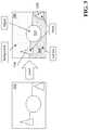
- FIG. 6is a diagram showing an exemplary volumetric probability model technique.
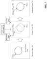
- FIG. 7is a workflow diagram of object region tracking.
- FIG. 8is a graph showing the performance of an exemplary machine learning classifier that detects drift.
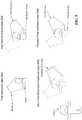
- FIG. 9is a workflow diagram of insertion and evaluation of keyframes.
- FIG. 10is a workflow diagram of removing noisy keyframes and re-adding keyframes after removing noise.
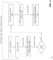
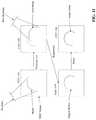
- FIG. 11is a workflow diagram of registration and merging of the volumetric model during tracking loss.
- FIG. 1is a block diagram of a system 100 for keyframe-based object scanning and tracking. Certain embodiments of the systems and methods described in this application utilize:
- the systemincludes a sensor 103 coupled to a computing device 104 .
- the computing device 104includes an image processing module 106 .
- the computing devicecan also be coupled to a data storage module 108 , e.g., used for storing certain 3D models, color images, and other data as described herein.
- the sensor 103is positioned to capture images (e.g., color images) of a scene 101 which includes one or more physical objects (e.g., object 102 ).
- a usermanually rotates and moves the object 102 in the scene 101 so that the sensor 103 captures a plurality of scans of the object from different angles and/or sides; in some embodiments, the user's hand is captured in the scans along with the object.
- Exemplary sensors that can be used in the system 100include, but are not limited to, time-of-flight (ToF) sensors that are capable of capturing depth information of the pixels along with the images of a real-world object and/or scene to collect data on its position, location, and appearance.
- Other types of sensorsinclude 3D scanners, digital cameras, and other types of devices.
- the sensor 103is embedded into the computing device 104 , such as a camera in a smartphone, for example.
- An exemplary sensor 103can be a 3D scanner built from combining a depth camera and a high-resolution RGB camera. The cameras can be calibrated so their data can be registered to each other.
- the sensor 103includes an Orbbec Astra Mini depth camera attached to, e.g., a mobile device with an embedded camera. It should be appreciated that other combinations of these devices or other devices can be used to perform the techniques described herein.
- the computing device 104receives images (also called scans) of the scene 101 from the sensor 103 and processes the images to generate 3D models of objects (e.g., object 102 ) represented in the scene 101 .
- the computing device 104can take on many forms, including both mobile and non-mobile forms. Exemplary computing devices include, but are not limited to, a laptop computer, a desktop computer, a tablet computer, a smartphone, a smart watch, an internet of things (IoT) device, augmented reality (AR)/virtual reality (VR) devices (e.g., glasses, headset apparatuses, and so forth), or the like.
- the sensor 103 and computing device 104can be embedded in a larger mobile structure such as a robot or unmanned aerial vehicle (UAV).
- UAVunmanned aerial vehicle
- the computing device 104includes network-interface components to connect to a communications network (not shown).
- the network-interface componentsinclude components to connect to a wireless network, such as a Wi-Fi or cellular network, in order to access a wider network, such as the Internet.
- the computing device 104includes an image processing module 106 configured to receive images captured by the sensor 103 and analyze the images in a variety of ways, including detecting the position and location of objects represented in the images and generating 3D models of objects in the images.
- the image processing module 106is a hardware and/or software module that resides on the computing device 104 to perform functions associated with analyzing images capture by the scanner, including the generation of 3D models (e.g., .OBJ files) based upon objects in the images.
- the functionality of the image processing module 106is distributed among a plurality of computing devices.
- the image processing module 106operates in conjunction with other modules that are either also located on the computing device 104 or on other computing devices coupled to the computing device 104 .
- An exemplary image processing module 106is the Starry Night SDK, available from VanGogh Imaging, Inc. of McLean, Va.
- the image processing module 106comprises specialized hardware (such as a processor or system-on-chip) that is embedded into, e.g., a circuit board or other similar component of another device.
- the image processing module 106is specifically programmed with the image processing and modeling software functionality described below.
- the computing device 104includes a machine learning classifier 107 , which is a specialized hardware and/or software module that can be trained with a set of object tracking training data to generate a classification model that automatically validates tracking (i.e., pose information) associated with one or more objects in the scene—as will be described in greater detail below.
- a machine learning classifier 107is a specialized hardware and/or software module that can be trained with a set of object tracking training data to generate a classification model that automatically validates tracking (i.e., pose information) associated with one or more objects in the scene—as will be described in greater detail below.
- the keyframe-based object reconstruction process described hereinuses a model that is defined by a set of keyframes.
- a volumetric modelis rebuilt from the keyframe set every time a keyframe is inserted or removed.
- Keyframesconsist of a color image, a depth image aligned to the color image, an estimated pose, and a labeling of all locations in the images into semantic categories.
- the volumetric modelcontains a truncated signed distance field (TSDF) and a probabilistic space labeling.
- the TSDFis generated by projecting each depth image into the model space based on its pose and describes the implicit surface of the object being scanned.
- the space labelingis created by analyzing the labels associated with the depth image and is used to classify points in future frames.
- the scanning systemis composed of a tracking and a mapping subsystem.
- the location of the objectis tracked against a model, which is built from select input frames.
- the systemrestarts construction at the new location while simultaneously trying to align the new map to the original.
- the systemtracks each frame individually in sequence.
- the systemUpon receiving a new frame of data, the system first attempts to label regions of the image that correspond to the desired object, unwanted foreground noise, and the background behind the object.
- the systemattempts to align the object portion of the input by aligning it with a combination of model parameters via several error terms.
- the first set of termscomes from the input 3D point cloud and an anchor point cloud rendered from the TSDF at the last estimated pose. Further terms are supplied by corner, edge, and 3d features in the keyframes close to the current frame.
- FIG. 2is a flow diagram of a computerized method 200 of keyframe-based object scanning and tracking, using the system 100 of FIG. 1 .
- the sensor 103captures one or more scans (also called frames or images) of the object 102 in the scene, and transmits a depth map and a color image for each scan to the image processing module 106 , for use as input to object tracking and model generation process.
- the image processing module 106labels ( 202 ) the input frame.
- each pixel in the depth image of each keyframeis labeled as either background, foreground noise, object, or unknown.
- background pixelsare those which must be behind the object. They imply there is no part of the object along the ray associated with that pixel.
- Object pixelsare those depth points corresponding to the object that the system is trying to track and reconstruct.
- Foreground noise pixelsare any points around the object that the system does not wish to track, including the user's hands or clutter in the environment. Parts of the object may be behind the foreground noise point.
- Unknown pixelsare those that cannot be accurately categorized or do not have any depth data.
- the image processing module 106generates label data (e.g., a mapping file that defines the pixel labels in conjunction with the depth/image data) and stores the generated label data in database 108 .
- Labelsare generated by examining each pixel's geometric relationship to the total scene geometry for that frame and the estimated model location. For instance, the image processing module 106 labels a group of points close to the camera surrounded by distant points as an object, while a point that is part of a large plane of points is probably part of the table on which the user is scanning, and the image processing module 106 labels the point as background.
- FIG. 3is a diagram showing how the system 100 labels portions of the keyframe.
- the image processing module 106receives an input keyframe 302 , and labels the sphere 304 in the middle of the keyframe as ‘object,’ labels a portion 306 of the keyframe as ‘background,’ labels another portion 308 of the keyframe as ‘surface,’ and labels certain regions 310 a , 310 b around the object as ‘noise.’
- the image processing module 106tracks ( 204 ) a region (i.e., an object region) of the labeled frame.
- a regioni.e., an object region
- FIG. 7is a workflow diagram of object region tracking, using the system 100 of FIG. 1 .
- the current input frame 702comprises a color and depth image, both already warped to a common alignment.
- the module 106also has a rough estimate of the pose 702 a of the object in the current input frame based on the optimized pose 704 a of the previous frame 704 .
- the module 106renders an anchor depth map 706 based on the implicit surface defined by the TSDF as well as identifying several nearby reference keyframes (e.g., 708 a , 708 b ).
- the module 106defines error terms between the current frame 702 and the anchor map 706 using projection iterative closest point (ICP), and further error terms between the current frame 702 and the reference keyframes 708 a , 708 b based on matching corner and edge features. Minimizing these terms gives the module 106 an optimal estimate 710 a for the current pose of the object (e.g., in an optimized frame 710 ).
- ICPprojection iterative closest point
- the module 106can then validate the tracking by comparing the current frame 702 to the individual keyframes 708 a , 708 b .
- a large error in several keyframesmay indicate that tracking was not successful, while a large error in a single keyframe may mean that the keyframe pose is inaccurate and should be removed.
- the module 106continues to track the object(s), the module 106 accumulates statistics about the reference keyframes used and how accurate they are compared to other nearby keyframes. Low-quality keyframes can be removed and high accuracy input frames can be saved as keyframes. This way, tracking and model quality continues to improve throughout the tracking process.
- the image processing module 106utilizes advanced algorithmic techniques described herein to train the machine learning classifier module 107 with a set of training data, then leverage the trained classifier 107 to automatically validate the tracking (e.g., the pose information).
- the module 106can encapsulate indicator values into a fixed-size vector of real numbers and a machine learning classifier 107 is trained using a large number of examples of these vectors individually labeled “true” or “false.”
- the classifier 107solves the incorrect pose problem, allowing the image processing module 106 to automatically find the best transformation for every set of data in a short amount of time.
- the training processproduces hard numbers proving exactly how good a given approach is.
- the image processing module 106In order to be confident in the output of training the machine learning classifier 107 , the image processing module 106 must have a statistically meaningful set of data which covers more-or-less all situations that one is interested in handling. As well, the larger the feature vector, the more data is needed. For a three-element vector, two hundred samples may be sufficient. A ten-element vector may require several thousand. There should be a similar number of “true” and “false” samples.
- data collectiontypically happens in rounds.
- An initial set of datais labeled and a classifier is trained.
- the classifiere.g., machine learning classifier 107
- the classifiercan then be tested using more data. If the classifier 107 performs well, then the training phase is complete. If not, the module 106 can add the incorrectly classified data to the training set. This approach deliberately trains the classifier 107 on the cases it would otherwise get wrong.
- the machine learning classifier 107uses logistic regression to find the best separating hyperplane between the data.
- the classifier 107starts by assigning “true” samples a value of 1 and “false” 0. Call this value y i for sample i.
- the module 106wants to find ⁇ that best approximates ⁇ x i , y i ⁇ for all i via the function
- the classifier 107finds this value by running Newton's method on a cost function summing errors for each data sample. The classifier 107 then rounds the predicted f(x) to either 0 or 1 to classify any new data. Alternatively, the classifier 107 can simply test if the dot product of ⁇ and x is greater or less than zero. This simple classification scheme has the advantage of being very fast, so it can be run every frame.
- FIG. 4is a flow diagram of a method for classifying pose information using machine learning.
- a feature seti.e., a set of input parameters to be classified
- the feature setcomprises three values: two values for dense error 412 and one value for sparse error 414 .
- the two values in the dense error feature 412are (i) the ratio of matched dense points to total points in the current model and (ii) the ratio of missing dense points to total points in the current 3D model.
- a matched pointis a point where the input depth map 402 value is within some small distance of the expected 3D model point value (as determined from the current pose 406 and anchor points 404 ).
- a missing pointis a point where the input depth map 402 value is much larger than the expected model point value, indicating that the image processing module 106 can see through where part of the 3D model is supposed to be if the pose was correct.
- the sparse error value 414is a count of the number of 2D ORB features 408 that currently can be seen and which have a close match in the keyframe 410 . It should be appreciated that the more matching ORB features, the more likely that the pose is correct.
- the image processing module 106generates a feature vector 416 from the dense error 412 values and the sparse error 414 value, and transmits the feature vector to the machine learning classifier 107 as input.
- the classifier 107executes to classify the vector as corresponding to an object pose that is correct (e.g., Yes) or incorrect (e.g., No) and generate associated output 418 for use by the module 106 .
- FIG. 5is a flow diagram for classifying object pose information using machine learning.
- the classifier 107can be used after tracking 508 every input frame, using the input sensor data 502 , anchor point data 504 , and keyframe data 506 (as described above). If the current pose is untrusted, such as when the image processing module 106 has recently re-localized (i.e., re-localization 512 ), the image processing module 106 uses the classifier 107 a as trained. Once the current pose is trusted, the machine learning classifier 107 b can include bias in the classification process (e.g., by lowering the passing threshold) to avoid having too many false positives.
- the classifier 107acts as both a validator for re-localization and a drifting check during normal tracking.
- the classifier 107 a or the classifier with bias 107 bexecutes to classify the vector as corresponding to an object pose that is correct (e.g., Yes) or incorrect (e.g., No) and generate associated output 510 for use by the image processing module 106 .
- FIG. 8is a graph showing the performance of an exemplary machine learning classifier (e.g., classifier 107 ) that detects drift. A positive result indicates that drifting has occurred.
- the graph of FIG. 8shows the tradeoff between the true positive rate (TPR), i.e. how many drifted frames were correctly identified, versus the false positive rate (FPR), i.e. how many correctly aligned frames were misclassified as drifted.
- TPRtrue positive rate
- FPRfalse positive rate
- Different bias levelscorrespond to different points on the curve.
- the point 802 labeled “no bias”presents an optimal balance between TPR and FPR for a single frame and is used during re-localization. However, during tracking the system can consider many similar frames in succession, so a large negative bias can be chosen (point 804 ), lowering the FPR at the cost of the TPR.
- the machine learning techniques described hereincan be used for any part of tracking where the image processing module 106 needs to accept or reject some value based on the current state.
- the image processing module 106can use the machine learning techniques to intelligently decide which features are more relevant versus others in order to provide more accurate pose calculation. The same regression and data analysis is valid for many classification tasks.
- the image processing module 106determines whether to keep the optimized frame and if so, the image processing module 106 selects ( 206 ) the optimized frame as a keyframe. For example, the current loose frame is considered for inclusion in the keyframe set based on a number of criteria, including uniqueness of position, strength of color features, confidence of the pose estimate, and presence of foreground noise.
- the module 106re-evaluates nearby keyframes to see if those nearby keyframes are now redundant. If so, the module 106 removes them, erasing their influence on the TSDF and object boundary.
- FIG. 9is a workflow diagram of insertion and evaluation of keyframes, using the system 100 of FIG. 1 .
- the object being scannedis a teddy bear.
- the image processing module 106captures a current loose frame as a first keyframe (step 902 ) that includes a model of the object.
- the image processing module 106adds other keyframes—for example, the module 106 can add a new keyframe (step 904 ); however, this keyframe may include a misaligned model of the object.
- the module 106can still determine whether nearby keyframes are now redundant (step 906 )—even for keyframes that may contain a misaligned model. The module 106 does not add the redundant keyframes. Then, the module 106 can remove poor or low-quality keyframes (step 908 ) and in some cases, can replace the removed keyframes with new keyframes that are of better quality.
- the keyframehas previously been labeled to identify, e.g., either background, foreground noise, object, or unknown pixels.
- the image processing module 106uses the keyframe labels to create probabilistic labels of the volumetric model. For each voxel in the volumetric model, the image processing module 106 projects the voxel to each keyframe and determines what information both the label (e.g., background, foreground noise, object, or unknown) and depth map can give about that location in space. For instance, by counting the number of times a particular voxel appears as either background, object, or in front of any depth point, the module 106 estimates the probability that the voxel either contains an object point or is empty.
- the labele.g., background, foreground noise, object, or unknown
- the module 106uses this estimate to influence future labels. For instance, if a new depth point under consideration lies in a voxel with a large chance of being empty then the module 106 can label the depth point as foreground noise, whereas if the voxel is frequently labeled as object, then the new point is probably an object point as well and the image processing module 106 can label the depth point as object.
- FIG. 6is a diagram showing an exemplary volumetric probability model technique used by the image processing module 106 .
- the image processing module 106projects each voxel to each keyframe 602 a , 602 b , 602 c and determines a probability that each voxel is part of the object (i.e., high object probability, white region 604 ) or is not part of the object (i.e., low object probability, shaded region 606 ).
- the image processing module 106also determines a projected object boundary 608 .
- the image processing module 106may not have enough information to reconstruct a smooth model. For example, if keyframes are noisy, the module 106 needs more keyframes to smooth out that noise. If the image processing module 106 and/or computing device 104 in general have limited memory, the module 106 needs to use fewer keyframes. In environments that are both noisy and constrained, the module 106 needs to combine multiple depth maps into a single keyframe. To do this, the image processing module 106 keeps a set of approximately thirty of the most recent aligned depth images.
- the module 106can combine the depth map of the selected frame with the set of most recent aligned depth maps, smoothing out noise and increasing the amount of information available in a single keyframe.
- the module 106can use fifty multi-frame keyframes and get the same quality results. This also allows the module 106 to run post-processing model adjustment faster than otherwise. Because many frames are already combined into one, there are fewer keyframes to adjust and optimize.
- the image processing moduleupdates ( 208 ) the volumetric model using the selected keyframe.
- the volumetric modelis an implicit surface defined by the estimated distance from each cell in the volume to the true surface of the object.
- the biggest advantage of maintaining a keyframe-based modelis the ability to easily modify the model to add, remove, or readjust input data to fix errors.
- the image processing module 106adds a keyframe to the volumetric model by averaging in the distance from each cell to the object's surface found in the keyframe. The module 106 can then remove the keyframe by subtracting this distance back out from the (potentially updated) cell average. Readjustment is equivalent to removing a keyframe and then re-adding it.
- FIG. 10is a workflow diagram of removing noisy keyframes and re-adding keyframes after removing noise, using the system 100 of FIG. 1 .
- the image processing module 106captures a current loose frame as a first keyframe (step 1002 ) that includes a model of the object.
- the image processing module 106may add a new keyframe that includes noise (step 1004 )—e.g., the arm of the teddy bear is not smooth.
- the module 106can remove the noisy keyframe (step 1006 ) and eliminate the noise (e.g., by smoothing the keyframe) then re-add the keyframe (step 1008 ) after removing the noise.
- Driftoccurs when the object is first scanned in a 360-degree arc.
- every small drifting error from frame to frameis added together to create a large error between the initial object pose and the current object pose.
- the module 106detects this during tracking, when the current input data may line up very well with one reference keyframe but not another.
- the image processing module 106fixes this problem by identifying the magnitude of the pose error and optimizing the keyframe poses to reduce this error. Once the keyframes are optimized, the module 106 can rebuild the volumetric model and continue scanning.
- the image processing module 106processes ( 210 ) the updated volumetric model to generate a final 3D model. It should be appreciated that, during scanning, especially with inexperienced users, it is fairly easy to lose tracking on the object. The naive strategy when this happens is to try to re-localize the object before continuing to scan. This requires the user to return the object to some previously scanned pose, perhaps trying several poses if re-localization is not working well. As a result, scanning time and user frustration increases.
- the system 100makes use of the fact that the volumetric model can be reconstituted from any set of keyframes.
- the image processing module 106starts by creating a new volumetric model, then merges this new model into the old model once the module 106 is able to register the two together. This allows the user to continue to scan and make progress on the model. While this new model is being built, the image processing module 106 searches for a registration between the new model and old model in a separate processing thread, then seamlessly merges the two together once the registration is found. If a registration cannot be found, the module 106 can wait and let the new model grow more detailed, making a second attempt at registration more likely to succeed. Merging the two models involves transforming the new model's keyframes into the coordinate system of the old model, combining all keyframes into one set, then rebuilding the volumetric model.
- FIG. 11is a workflow diagram of registration and merging of the volumetric model during tracking loss, using the system 100 of FIG. 1 .
- the image processing module 106generates a model (step 1102 ) using the TSDF volume and keyframe. If tracking is lost while the image processing module 106 builds the model using a new keyframe, the module 106 can simply create a new model (step 1104 ).
- the module 106searches for a registration between the new model and old model in a separate processing thread (step 1106 )—for example, given any number of models, the module 106 repeatedly tries to combine the current model with any of the older ones. Once the module 106 finds a registration between an old model and the new model, the module 106 merges the two models together (step 1108 ). This eventually leads back to a single unified model once the object has been fully scanned.
- the above-described techniquescan be implemented in digital and/or analog electronic circuitry, or in computer hardware, firmware, software, or in combinations of them.
- the implementationcan be as a computer program product, i.e., a computer program tangibly embodied in a machine-readable storage device, for execution by, or to control the operation of, a data processing apparatus, e.g., a programmable processor, a computer, and/or multiple computers.
- a computer programcan be written in any form of computer or programming language, including source code, compiled code, interpreted code and/or machine code, and the computer program can be deployed in any form, including as a stand-alone program or as a subroutine, element, or other unit suitable for use in a computing environment.
- a computer programcan be deployed to be executed on one computer or on multiple computers at one or more sites.
- Method stepscan be performed by one or more specialized processors executing a computer program to perform functions by operating on input data and/or generating output data. Method steps can also be performed by, and an apparatus can be implemented as, special purpose logic circuitry, e.g., a FPGA (field programmable gate array), a FPAA (field-programmable analog array), a CPLD (complex programmable logic device), a PSoC (Programmable System-on-Chip), ASIP (application-specific instruction-set processor), or an ASIC (application-specific integrated circuit), or the like.
- Subroutinescan refer to portions of the stored computer program and/or the processor, and/or the special circuitry that implement one or more functions.
- processors suitable for the execution of a computer programinclude, by way of example, special purpose microprocessors.
- a processorreceives instructions and data from a read-only memory or a random access memory or both.
- the essential elements of a computerare a processor for executing instructions and one or more memory devices for storing instructions and/or data.
- Memory devicessuch as a cache, can be used to temporarily store data. Memory devices can also be used for long-term data storage.
- a computeralso includes, or is operatively coupled to receive data from or transfer data to, or both, one or more mass storage devices for storing data, e.g., magnetic, magneto-optical disks, or optical disks.
- a computercan also be operatively coupled to a communications network in order to receive instructions and/or data from the network and/or to transfer instructions and/or data to the network.
- Computer-readable storage mediums suitable for embodying computer program instructions and datainclude all forms of volatile and non-volatile memory, including by way of example semiconductor memory devices, e.g., DRAM, SRAM, EPROM, EEPROM, and flash memory devices; magnetic disks, e.g., internal hard disks or removable disks; magneto-optical disks; and optical disks, e.g., CD, DVD, HD-DVD, and Blu-ray disks.
- the processor and the memorycan be supplemented by and/or incorporated in special purpose logic circuitry.
- the above described techniquescan be implemented on a computer in communication with a display device, e.g., a CRT (cathode ray tube), plasma, or LCD (liquid crystal display) monitor, for displaying information to the user and a keyboard and a pointing device, e.g., a mouse, a trackball, a touchpad, or a motion sensor, by which the user can provide input to the computer (e.g., interact with a user interface element).
- a display devicee.g., a CRT (cathode ray tube), plasma, or LCD (liquid crystal display) monitor
- a keyboard and a pointing devicee.g., a mouse, a trackball, a touchpad, or a motion sensor, by which the user can provide input to the computer (e.g., interact with a user interface element).
- feedback provided to the usercan be any form of sensory feedback, e.g., visual feedback, auditory feedback, or tactile feedback; and input from the user can be received in any form, including acoustic, speech, and/or tactile input.
- feedback provided to the usercan be any form of sensory feedback, e.g., visual feedback, auditory feedback, or tactile feedback
- input from the usercan be received in any form, including acoustic, speech, and/or tactile input.
- the above described techniquescan be implemented in a distributed computing system that includes a back-end component.
- the back-end componentcan, for example, be a data server, a middleware component, and/or an application server.
- the above described techniquescan be implemented in a distributed computing system that includes a front-end component.
- the front-end componentcan, for example, be a client computer having a graphical user interface, a Web browser through which a user can interact with an example implementation, and/or other graphical user interfaces for a transmitting device.
- the above described techniquescan be implemented in a distributed computing system that includes any combination of such back-end, middleware, or front-end components.
- Transmission mediumcan include any form or medium of digital or analog data communication (e.g., a communication network).
- Transmission mediumcan include one or more packet-based networks and/or one or more circuit-based networks in any configuration.
- Packet-based networkscan include, for example, the Internet, a carrier internet protocol (IP) network (e.g., local area network (LAN), wide area network (WAN), campus area network (CAN), metropolitan area network (MAN), home area network (HAN)), a private IP network, an IP private branch exchange (IPBX), a wireless network (e.g., radio access network (RAN), Bluetooth, Wi-Fi, WiMAX, general packet radio service (GPRS) network, HiperLAN), and/or other packet-based networks.
- IPcarrier internet protocol
- RANradio access network
- GPRSgeneral packet radio service
- HiperLANHiperLAN
- Circuit-based networkscan include, for example, the public switched telephone network (PSTN), a legacy private branch exchange (PBX), a wireless network (e.g., RAN, code-division multiple access (CDMA) network, time division multiple access (TDMA) network, global system for mobile communications (GSM) network), and/or other circuit-based networks.
- PSTNpublic switched telephone network
- PBXlegacy private branch exchange
- CDMAcode-division multiple access
- TDMAtime division multiple access
- GSMglobal system for mobile communications
- Communication protocolscan include, for example, Ethernet protocol, Internet Protocol (IP), Voice over IP (VOIP), a Peer-to-Peer (P2P) protocol, Hypertext Transfer Protocol (HTTP), Session Initiation Protocol (SIP), H.323, Media Gateway Control Protocol (MGCP), Signaling System #7 (SS7), a Global System for Mobile Communications (GSM) protocol, a Push-to-Talk (PTT) protocol, a PTT over Cellular (POC) protocol, Universal Mobile Telecommunications System (UMTS), 3GPP Long Term Evolution (LTE) and/or other communication protocols.
- IPInternet Protocol
- VOIPVoice over IP
- P2PPeer-to-Peer
- HTTPHypertext Transfer Protocol
- SIPSession Initiation Protocol
- H.323H.323
- MGCPMedia Gateway Control Protocol
- SS7Signaling System #7
- GSMGlobal System for Mobile Communications
- PTTPush-to-Talk
- POCPTT over Cellular
- UMTS
- Devices of the computing systemcan include, for example, a computer, a computer with a browser device, a telephone, an IP phone, a mobile device (e.g., cellular phone, personal digital assistant (PDA) device, smart phone, tablet, laptop computer, electronic mail device), and/or other communication devices.
- the browser deviceincludes, for example, a computer (e.g., desktop computer and/or laptop computer) with a World Wide Web browser (e.g., ChromeTM from Google, Inc., Microsoft® Internet Explorer® available from Microsoft Corporation, and/or Mozilla® Firefox available from Mozilla Corporation).
- Mobile computing deviceinclude, for example, a Blackberry® from Research in Motion, an iPhone® from Apple Corporation, and/or an AndroidTM-based device.
- IP phonesinclude, for example, a Cisco® Unified IP Phone 7985G and/or a Cisco® Unified Wireless Phone 7920 available from Cisco Systems, Inc.
- Comprise, include, and/or plural forms of eachare open ended and include the listed parts and can include additional parts that are not listed. And/or is open ended and includes one or more of the listed parts and combinations of the listed parts.
Landscapes
- Engineering & Computer Science (AREA)
- Theoretical Computer Science (AREA)
- Physics & Mathematics (AREA)
- General Physics & Mathematics (AREA)
- Software Systems (AREA)
- Computer Vision & Pattern Recognition (AREA)
- Evolutionary Computation (AREA)
- Artificial Intelligence (AREA)
- Multimedia (AREA)
- Computing Systems (AREA)
- Data Mining & Analysis (AREA)
- General Engineering & Computer Science (AREA)
- Medical Informatics (AREA)
- Mathematical Physics (AREA)
- Health & Medical Sciences (AREA)
- General Health & Medical Sciences (AREA)
- Life Sciences & Earth Sciences (AREA)
- Computer Graphics (AREA)
- Geometry (AREA)
- Databases & Information Systems (AREA)
- Biomedical Technology (AREA)
- Biophysics (AREA)
- Computational Linguistics (AREA)
- Molecular Biology (AREA)
- Bioinformatics & Cheminformatics (AREA)
- Bioinformatics & Computational Biology (AREA)
- Evolutionary Biology (AREA)
- Image Analysis (AREA)
Abstract
Description
- the object recognition, reconstruction, and analysis techniques as described in U.S. Pat. No. 9,715,761, titled “Real-Time 3D Computer Vision Processing Engine for Object Recognition, Reconstruction, and Analysis;”
- the dynamic 3D modeling techniques as described in U.S. patent application Ser. No. 14/849,172, titled “Real-Time Dynamic Three-Dimensional Adaptive Object Recognition and Model Reconstruction;”
- the shape-based registration and modeling techniques described in U.S. Pat. No. 10,169,676, titled “Shape-Based Registration for Non-Rigid Objects with Large Holes;”
- the 3D photogrammetry techniques described in U.S. Pat. No. 10,192,347, titled “3D Photogrammetry;”
- the sparse SLAM and unified tracking techniques as described in U.S. patent application Ser. No. 15/638,278, titled “Sparse Simultaneous Localization and Matching with Unified Tracking;”
- the 2D and 3D video compression techniques described in U.S. patent application Ser. No. 15/726,316, titled “Real-Time Remote Collaboration and Virtual Presence using Simultaneous Localization and Mapping to Construct a 3D Model and Update a Scene Based on Sparse Data;”
- the object tracking techniques as described in U.S. patent application Ser. No. 16/123,256, titled “Combining Sparse Two-Dimensional (2D) and Dense Three-Dimensional (3D) Tracking;”
- the 4D hologram technology described in U.S. patent application Ser. No. 16/240,404, titled “4D Hologram: Real-Time Remote Avatar Creation and Animation Control;”
- the real-time texture alignment techniques described in U.S. patent application Ser. No. 16/374,023, titled “Dynamic Real-Time Texture Alignment for 3D Models;”
- the 3D capture techniques described in U.S. Provisional Patent Application No. 62/843,680, titled “3D Capture Using Edge Cloud Computing Resources;” and
- the remote 3D animation techniques described in U.S. Provisional Patent Application No. 62/843,683, titled “Remote Visualization of 3D Animation With Synchronized Voice in Time.”
Claims (24)
Priority Applications (1)
| Application Number | Priority Date | Filing Date | Title |
|---|---|---|---|
| US16/421,822US11170224B2 (en) | 2018-05-25 | 2019-05-24 | Keyframe-based object scanning and tracking |
Applications Claiming Priority (3)
| Application Number | Priority Date | Filing Date | Title |
|---|---|---|---|
| US201862676507P | 2018-05-25 | 2018-05-25 | |
| US201962789309P | 2019-01-07 | 2019-01-07 | |
| US16/421,822US11170224B2 (en) | 2018-05-25 | 2019-05-24 | Keyframe-based object scanning and tracking |
Publications (2)
| Publication Number | Publication Date |
|---|---|
| US20190362157A1 US20190362157A1 (en) | 2019-11-28 |
| US11170224B2true US11170224B2 (en) | 2021-11-09 |
Family
ID=68614682
Family Applications (1)
| Application Number | Title | Priority Date | Filing Date |
|---|---|---|---|
| US16/421,822Active2039-10-17US11170224B2 (en) | 2018-05-25 | 2019-05-24 | Keyframe-based object scanning and tracking |
Country Status (1)
| Country | Link |
|---|---|
| US (1) | US11170224B2 (en) |
Cited By (2)
| Publication number | Priority date | Publication date | Assignee | Title |
|---|---|---|---|---|
| US11410315B2 (en)* | 2019-11-16 | 2022-08-09 | Uatc, Llc | High quality instance segmentation |
| US11816231B2 (en) | 2021-11-22 | 2023-11-14 | Bank Of America Corporation | Using machine-learning models to determine graduated levels of access to secured data for remote devices |
Families Citing this family (14)
| Publication number | Priority date | Publication date | Assignee | Title |
|---|---|---|---|---|
| KR102455468B1 (en)* | 2018-06-22 | 2022-10-19 | 한국전자통신연구원 | Method and apparatus for reconstructing three dimensional model of object |
| DE102018126855A1 (en)* | 2018-10-26 | 2020-04-30 | Visualix GmbH | Device and method for determining the position in a 3D model of an environment |
| US11600068B2 (en)* | 2019-08-20 | 2023-03-07 | Dilili Labs, Inc. | Systems, methods, and storage media for processing digital video |
| US11037531B2 (en)* | 2019-10-24 | 2021-06-15 | Facebook Technologies, Llc | Neural reconstruction of sequential frames |
| US11080862B2 (en)* | 2019-11-18 | 2021-08-03 | Ncku Research And Development Foundation | Reliability based keyframe switching system and method adaptable to ICP |
| CN111724439B (en)* | 2019-11-29 | 2024-05-17 | 中国科学院上海微系统与信息技术研究所 | Visual positioning method and device under dynamic scene |
| US20210209377A1 (en)* | 2020-01-03 | 2021-07-08 | Cawamo Ltd | System and method for identifying events of interest in images from one or more imagers in a computing network |
| US12127085B2 (en)* | 2020-07-29 | 2024-10-22 | Aurora Operations, Inc. | Systems and methods for mitigating vehicle pose error across an aggregated feature map |
| US11113894B1 (en)* | 2020-09-11 | 2021-09-07 | Microsoft Technology Licensing, Llc | Systems and methods for GPS-based and sensor-based relocalization |
| CN112750201B (en)* | 2021-01-15 | 2024-03-29 | 浙江商汤科技开发有限公司 | Three-dimensional reconstruction method, related device and equipment |
| US12173469B2 (en) | 2021-04-20 | 2024-12-24 | Deere & Company | Apparatus and method for grade control |
| CN113284176B (en)* | 2021-06-04 | 2022-08-16 | 深圳积木易搭科技技术有限公司 | Online matching optimization method combining geometry and texture and three-dimensional scanning system |
| US12223676B2 (en)* | 2022-05-26 | 2025-02-11 | Htc Corporation | Method for pose correction and host |
| CN118629003B (en)* | 2024-05-23 | 2025-03-04 | 中兵智能创新研究院有限公司 | Dynamic environment vision SLAM method based on previous frame memory and DCP network layer |
Citations (110)
| Publication number | Priority date | Publication date | Assignee | Title |
|---|---|---|---|---|
| US5675326A (en) | 1990-04-11 | 1997-10-07 | Auto-Sense, Ltd. | Method of determining optimal detection beam locations using reflective feature mapping |
| US6259815B1 (en) | 1999-03-04 | 2001-07-10 | Mitsubishi Electric Research Laboratories, Inc. | System and method for recognizing scanned objects with deformable volumetric templates |
| US6275235B1 (en) | 1998-12-21 | 2001-08-14 | Silicon Graphics, Inc. | High precision texture wrapping method and device |
| US6525722B1 (en) | 1995-08-04 | 2003-02-25 | Sun Microsystems, Inc. | Geometry compression for regular and irregular mesh structures |
| US6525725B1 (en) | 2000-03-15 | 2003-02-25 | Sun Microsystems, Inc. | Morphing decompression in a graphics system |
| EP1308902A2 (en) | 2001-11-05 | 2003-05-07 | Canon Europa N.V. | Three-dimensional computer modelling |
| US20050068317A1 (en) | 2002-06-28 | 2005-03-31 | Fujitsu Limited | Program, method, and device for comparing three-dimensional images in voxel form |
| US20050128201A1 (en) | 2003-12-12 | 2005-06-16 | Warner Michael S. | Method and system for system visualization |
| US20050253924A1 (en) | 2004-05-13 | 2005-11-17 | Ken Mashitani | Method and apparatus for processing three-dimensional images |
| US20060050952A1 (en) | 2004-09-03 | 2006-03-09 | Francois Blais | Recursive 3D model optimization |
| WO2006027339A2 (en) | 2004-09-06 | 2006-03-16 | The European Community, Represented By The European Commission | Method and system for 3d scene change detection |
| US20060170695A1 (en) | 2005-01-28 | 2006-08-03 | Microsoft Corporation | Decorating surfaces with textures |
| US20060277454A1 (en) | 2003-12-09 | 2006-12-07 | Yi-Chih Chen | Multimedia presentation system |
| US20070075997A1 (en) | 2005-09-22 | 2007-04-05 | Janos Rohaly | Artifact mitigation in three-dimensional imaging |
| US20070122001A1 (en)* | 2005-11-30 | 2007-05-31 | Microsoft Corporation | Real-time Bayesian 3D pose tracking |
| US7248257B2 (en) | 2001-02-14 | 2007-07-24 | Technion Research & Development Foundation Ltd. | Low bandwidth transmission of 3D graphical data |
| US20070216675A1 (en)* | 2006-03-16 | 2007-09-20 | Microsoft Corporation | Digital Video Effects |
| US20080181486A1 (en)* | 2007-01-26 | 2008-07-31 | Conversion Works, Inc. | Methodology for 3d scene reconstruction from 2d image sequences |
| US20080180448A1 (en) | 2006-07-25 | 2008-07-31 | Dragomir Anguelov | Shape completion, animation and marker-less motion capture of people, animals or characters |
| US7420555B1 (en) | 2002-12-02 | 2008-09-02 | Ngrain (Canada) Corporation | Method and apparatus for transforming point cloud data to volumetric data |
| US20080310757A1 (en) | 2007-06-15 | 2008-12-18 | George Wolberg | System and related methods for automatically aligning 2D images of a scene to a 3D model of the scene |
| US20090232353A1 (en) | 2006-11-10 | 2009-09-17 | University Of Maryland | Method and system for markerless motion capture using multiple cameras |
| US20100111370A1 (en) | 2008-08-15 | 2010-05-06 | Black Michael J | Method and apparatus for estimating body shape |
| US20100198563A1 (en) | 2009-02-03 | 2010-08-05 | Thomas Plewe | Systems and methods for component-based architecture design |
| US20100209013A1 (en) | 2009-02-13 | 2010-08-19 | Harris Corporation | Registration of 3d point cloud data to 2d electro-optical image data |
| US20100302247A1 (en) | 2009-05-29 | 2010-12-02 | Microsoft Corporation | Target digitization, extraction, and tracking |
| US20110052043A1 (en) | 2009-08-25 | 2011-03-03 | Samsung Electronics Co., Ltd. | Method of mobile platform detecting and tracking dynamic objects and computer-readable medium thereof |
| US20110063403A1 (en)* | 2009-09-16 | 2011-03-17 | Microsoft Corporation | Multi-camera head pose tracking |
| US20110074929A1 (en) | 2005-03-11 | 2011-03-31 | Hebert Patrick | Auto-referenced sensing device for three-dimensional scanning |
| KR101054736B1 (en) | 2010-05-04 | 2011-08-05 | 성균관대학교산학협력단 | 3D object recognition and attitude estimation method |
| KR20110116671A (en) | 2010-04-20 | 2011-10-26 | 삼성전자주식회사 | Mesh generating apparatus and method, and image processing apparatus and method |
| US20120056800A1 (en) | 2010-09-07 | 2012-03-08 | Microsoft Corporation | System for fast, probabilistic skeletal tracking |
| US20120063672A1 (en) | 2006-11-21 | 2012-03-15 | Mantis Vision Ltd. | 3d geometric modeling and motion capture using both single and dual imaging |
| US20120098937A1 (en) | 2009-04-28 | 2012-04-26 | Behzad Sajadi | Markerless Geometric Registration Of Multiple Projectors On Extruded Surfaces Using An Uncalibrated Camera |
| US20120130762A1 (en) | 2010-11-18 | 2012-05-24 | Navteq North America, Llc | Building directory aided navigation |
| US8209144B1 (en) | 2009-09-15 | 2012-06-26 | Google Inc. | Accurate alignment of multiple laser scans using a template surface |
| US20120194516A1 (en) | 2011-01-31 | 2012-08-02 | Microsoft Corporation | Three-Dimensional Environment Reconstruction |
| US20120194517A1 (en) | 2011-01-31 | 2012-08-02 | Microsoft Corporation | Using a Three-Dimensional Environment Model in Gameplay |
| US20120306876A1 (en) | 2011-06-06 | 2012-12-06 | Microsoft Corporation | Generating computer models of 3d objects |
| US20130069940A1 (en) | 2011-09-21 | 2013-03-21 | University Of South Florida (A Florida Non-Profit Corporation) | Systems And Methods For Projecting Images Onto An Object |
| US20130123801A1 (en) | 2011-11-15 | 2013-05-16 | Macdonald Dettwiler & Associates | Method of real-time tracking of moving/flexible surfaces |
| US20130156262A1 (en) | 2011-12-19 | 2013-06-20 | Yuichi Taguchi | Voting-Based Pose Estimation for 3D Sensors |
| US20130201104A1 (en) | 2012-02-02 | 2013-08-08 | Raymond William Ptucha | Multi-user interactive display system |
| US20130201105A1 (en) | 2012-02-02 | 2013-08-08 | Raymond William Ptucha | Method for controlling interactive display system |
| US20130208955A1 (en) | 2012-02-14 | 2013-08-15 | Tiecheng Zhao | Cloud-based medical image processing system with access control |
| US8542233B2 (en) | 2006-05-04 | 2013-09-24 | Battle M. Brown | Systems and methods for photogrammetric rendering |
| US20140160115A1 (en) | 2011-04-04 | 2014-06-12 | Peter Keitler | System And Method For Visually Displaying Information On Real Objects |
| US20140176677A1 (en) | 2005-09-09 | 2014-06-26 | Industrial Research Limited | 3D Scene Scanner and Position and Orientation System |
| US8766979B2 (en) | 2012-01-20 | 2014-07-01 | Vangogh Imaging, Inc. | Three dimensional data compression |
| US20140206443A1 (en) | 2013-01-24 | 2014-07-24 | Microsoft Corporation | Camera pose estimation for 3d reconstruction |
| US20140241617A1 (en) | 2013-02-22 | 2014-08-28 | Microsoft Corporation | Camera/object pose from predicted coordinates |
| US20140240464A1 (en) | 2013-02-28 | 2014-08-28 | Motorola Mobility Llc | Context-Based Depth Sensor Control |
| US20140270484A1 (en) | 2013-03-14 | 2014-09-18 | Nec Laboratories America, Inc. | Moving Object Localization in 3D Using a Single Camera |
| US20140321702A1 (en) | 2013-04-30 | 2014-10-30 | Qualcomm Incorporated | Diminished and mediated reality effects from reconstruction |
| US20150009214A1 (en) | 2013-07-08 | 2015-01-08 | Vangogh Imaging, Inc. | Real-time 3d computer vision processing engine for object recognition, reconstruction, and analysis |
| US8942917B2 (en) | 2011-02-14 | 2015-01-27 | Microsoft Corporation | Change invariant scene recognition by an agent |
| US20150045923A1 (en) | 2013-08-07 | 2015-02-12 | Fu Tai Hua Industry (Shenzhen) Co., Ltd. | Material cutting optimization apparatus, system, and method |
| US8995756B2 (en) | 2012-09-27 | 2015-03-31 | Vangogh Imaging, Inc. | 3D vision processing |
| US20150142394A1 (en) | 2013-11-18 | 2015-05-21 | Dassault Systemés | Computing Camera Parameters |
| US9041711B1 (en) | 2012-05-08 | 2015-05-26 | Google Inc. | Generating reduced resolution textured model from higher resolution model |
| US20150213572A1 (en) | 2014-01-24 | 2015-07-30 | Here Global B.V. | Methods, apparatuses and computer program products for three dimensional segmentation and textured modeling of photogrammetry surface meshes |
| US9104908B1 (en) | 2012-05-22 | 2015-08-11 | Image Metrics Limited | Building systems for adaptive tracking of facial features across individuals and groups |
| US20150234477A1 (en) | 2013-07-12 | 2015-08-20 | Magic Leap, Inc. | Method and system for determining user input based on gesture |
| US20150262405A1 (en) | 2012-10-05 | 2015-09-17 | Max-Planck-Gesellschaft Zur Foerderung Der Wissenschaften E. V. | Co-registration - simultaneous alignment and modeling of articulated 3d shapes |
| US20150269715A1 (en) | 2014-03-19 | 2015-09-24 | Samsung Electronics Co., Ltd. | Electronic device and method for processing an image |
| US20150279118A1 (en) | 2014-03-25 | 2015-10-01 | Cisco Technology, Inc. | Scanning and Tracking Dynamic Objects with Depth Cameras |
| US20150301592A1 (en) | 2014-04-18 | 2015-10-22 | Magic Leap, Inc. | Utilizing totems for augmented or virtual reality systems |
| US9171402B1 (en) | 2013-06-19 | 2015-10-27 | Google Inc. | View-dependent textures for interactive geographic information system |
| US20150325044A1 (en) | 2014-05-09 | 2015-11-12 | Adornably, Inc. | Systems and methods for three-dimensional model texturing |
| US20150371440A1 (en) | 2014-06-19 | 2015-12-24 | Qualcomm Incorporated | Zero-baseline 3d map initialization |
| US20160026253A1 (en) | 2014-03-11 | 2016-01-28 | Magic Leap, Inc. | Methods and systems for creating virtual and augmented reality |
| US20160071318A1 (en) | 2014-09-10 | 2016-03-10 | Vangogh Imaging, Inc. | Real-Time Dynamic Three-Dimensional Adaptive Object Recognition and Model Reconstruction |
| US20160163098A1 (en)* | 2013-05-31 | 2016-06-09 | Longsand Limited | Three-dimensional object modeling |
| US20160173842A1 (en) | 2014-12-11 | 2016-06-16 | Texas Instruments Incorporated | Camera-Assisted Two Dimensional Keystone Correction |
| US20160171765A1 (en) | 2014-12-10 | 2016-06-16 | Dassault Systemes | Texturing a 3d modeled object |
| US20160358382A1 (en) | 2015-06-04 | 2016-12-08 | Vangogh Imaging, Inc. | Augmented Reality Using 3D Depth Sensor and 3D Projection |
| US20170054965A1 (en) | 2015-08-19 | 2017-02-23 | Faro Technologies, Inc. | Three-dimensional imager |
| US20170053447A1 (en) | 2015-08-20 | 2017-02-23 | Microsoft Technology Licensing, Llc | Augmented Reality |
| US20170054954A1 (en) | 2011-04-04 | 2017-02-23 | EXTEND3D GmbH | System and method for visually displaying information on real objects |
| US9607388B2 (en) | 2014-09-19 | 2017-03-28 | Qualcomm Incorporated | System and method of pose estimation |
| US9710960B2 (en) | 2014-12-04 | 2017-07-18 | Vangogh Imaging, Inc. | Closed-form 3D model generation of non-rigid complex objects from incomplete and noisy scans |
| US20170221263A1 (en) | 2016-01-29 | 2017-08-03 | Magic Leap, Inc. | Orthogonal-Projection-Based Texture Atlas Packing of Three-Dimensional Meshes |
| US20170243397A1 (en) | 2016-02-24 | 2017-08-24 | Vangogh Imaging, Inc. | Shape-based registration for non-rigid objects with large holes |
| US20170249752A1 (en)* | 2016-02-29 | 2017-08-31 | Canon Kabushiki Kaisha | Device for measuring position and orientation of imaging apparatus and method therefor |
| US20170278293A1 (en) | 2013-07-18 | 2017-09-28 | Google Inc. | Processing a Texture Atlas Using Manifold Neighbors |
| US20170316597A1 (en) | 2016-04-29 | 2017-11-02 | Adobe Systems Incorporated | Texturing a three-dimensional scanned model with localized patch colors |
| US20170316612A1 (en)* | 2016-04-28 | 2017-11-02 | Fujitsu Limited | Authoring device and authoring method |
| US20170337726A1 (en) | 2016-05-17 | 2017-11-23 | Vangogh Imaging, Inc. | 3d photogrammetry |
| US20180005015A1 (en)* | 2016-07-01 | 2018-01-04 | Vangogh Imaging, Inc. | Sparse simultaneous localization and matching with unified tracking |
| US20180025529A1 (en) | 2015-03-09 | 2018-01-25 | Carestream Health, Inc. | Apparatus and method of texture mapping for dental 3d scanner |
| US20180114363A1 (en) | 2016-10-25 | 2018-04-26 | Microsoft Technology Licensing, Llc | Augmented scanning of 3d models |
| US9978177B2 (en) | 2015-12-31 | 2018-05-22 | Dassault Systemes | Reconstructing a 3D modeled object |
| US20180144535A1 (en) | 2014-06-06 | 2018-05-24 | Matterport, Inc. | Optimal texture memory allocation |
| US20180218513A1 (en)* | 2017-02-02 | 2018-08-02 | Intel Corporation | Method and system of automatic object dimension measurement by using image processing |
| US20180288387A1 (en) | 2017-03-29 | 2018-10-04 | Intel Corporation | Real-time capturing, processing, and rendering of data for enhanced viewing experiences |
| US20180300937A1 (en) | 2017-04-13 | 2018-10-18 | National Taiwan University | System and a method of restoring an occluded background region |
| US20190026942A1 (en)* | 2017-07-18 | 2019-01-24 | Sony Corporation | Robust mesh tracking and fusion by using part-based key frames and priori model |
| US20190073825A1 (en) | 2017-09-01 | 2019-03-07 | Vangogh Imaging, Inc. | Enhancing depth sensor-based 3d geometry reconstruction with photogrammetry |
| US20190073787A1 (en) | 2017-09-07 | 2019-03-07 | Vangogh Imaging, Inc. | Combining sparse two-dimensional (2d) and dense three-dimensional (3d) tracking |
| US20190208007A1 (en) | 2018-01-03 | 2019-07-04 | Verizon Patent And Licensing Inc. | Edge Compute Systems and Methods |
| US20190206116A1 (en)* | 2017-12-28 | 2019-07-04 | Beijing Jingdong Shangke Information Technology Co., Ltd. | System and method for monocular simultaneous localization and mapping |
| US20190213773A1 (en) | 2018-01-05 | 2019-07-11 | Vangogh Imaging, Inc. | 4d hologram: real-time remote avatar creation and animation control |
| US20190220775A1 (en)* | 2018-01-15 | 2019-07-18 | Canon Kabushiki Kaisha | Information processing apparatus, system, information processing method, and non-transitory computer-readable storage medium |
| US20190226852A1 (en)* | 2016-09-09 | 2019-07-25 | Nanyang Technological University | Simultaneous localization and mapping methods and apparatus |
| US20190234746A1 (en)* | 2016-09-14 | 2019-08-01 | Zhejiang University | Method for simultaneous localization and mapping |
| US20190244412A1 (en) | 2018-02-06 | 2019-08-08 | A9.Com, Inc. | Photorealistic three dimensional texturing using canonical views and a two-stage approach |
| US20190304161A1 (en) | 2018-04-03 | 2019-10-03 | Vangogh Imaging, Inc. | Dynamic real-time texture alignment for 3d models |
| US20200086487A1 (en) | 2018-09-13 | 2020-03-19 | The Charles Stark Draper Laboratory, Inc. | Robot Interaction With Human Co-Workers |
| US20200105013A1 (en) | 2016-04-27 | 2020-04-02 | Bellus3D | Robust Head Pose Estimation with a Depth Camera |
| US20200334842A1 (en)* | 2018-02-23 | 2020-10-22 | Sony Corporation | Methods, devices and computer program products for global bundle adjustment of 3d images |
- 2019
- 2019-05-24USUS16/421,822patent/US11170224B2/enactiveActive
Patent Citations (112)
| Publication number | Priority date | Publication date | Assignee | Title |
|---|---|---|---|---|
| US5675326A (en) | 1990-04-11 | 1997-10-07 | Auto-Sense, Ltd. | Method of determining optimal detection beam locations using reflective feature mapping |
| US6525722B1 (en) | 1995-08-04 | 2003-02-25 | Sun Microsystems, Inc. | Geometry compression for regular and irregular mesh structures |
| US6275235B1 (en) | 1998-12-21 | 2001-08-14 | Silicon Graphics, Inc. | High precision texture wrapping method and device |
| US6259815B1 (en) | 1999-03-04 | 2001-07-10 | Mitsubishi Electric Research Laboratories, Inc. | System and method for recognizing scanned objects with deformable volumetric templates |
| US6525725B1 (en) | 2000-03-15 | 2003-02-25 | Sun Microsystems, Inc. | Morphing decompression in a graphics system |
| US7248257B2 (en) | 2001-02-14 | 2007-07-24 | Technion Research & Development Foundation Ltd. | Low bandwidth transmission of 3D graphical data |
| EP1308902A2 (en) | 2001-11-05 | 2003-05-07 | Canon Europa N.V. | Three-dimensional computer modelling |
| US20050068317A1 (en) | 2002-06-28 | 2005-03-31 | Fujitsu Limited | Program, method, and device for comparing three-dimensional images in voxel form |
| US7420555B1 (en) | 2002-12-02 | 2008-09-02 | Ngrain (Canada) Corporation | Method and apparatus for transforming point cloud data to volumetric data |
| US20060277454A1 (en) | 2003-12-09 | 2006-12-07 | Yi-Chih Chen | Multimedia presentation system |
| US20050128201A1 (en) | 2003-12-12 | 2005-06-16 | Warner Michael S. | Method and system for system visualization |
| US20050253924A1 (en) | 2004-05-13 | 2005-11-17 | Ken Mashitani | Method and apparatus for processing three-dimensional images |
| US7657081B2 (en) | 2004-09-03 | 2010-02-02 | National Research Council Of Canada | Recursive 3D model optimization |
| US20060050952A1 (en) | 2004-09-03 | 2006-03-09 | Francois Blais | Recursive 3D model optimization |
| WO2006027339A2 (en) | 2004-09-06 | 2006-03-16 | The European Community, Represented By The European Commission | Method and system for 3d scene change detection |
| US20060170695A1 (en) | 2005-01-28 | 2006-08-03 | Microsoft Corporation | Decorating surfaces with textures |
| US20110074929A1 (en) | 2005-03-11 | 2011-03-31 | Hebert Patrick | Auto-referenced sensing device for three-dimensional scanning |
| US20140176677A1 (en) | 2005-09-09 | 2014-06-26 | Industrial Research Limited | 3D Scene Scanner and Position and Orientation System |
| US20070075997A1 (en) | 2005-09-22 | 2007-04-05 | Janos Rohaly | Artifact mitigation in three-dimensional imaging |
| US20070122001A1 (en)* | 2005-11-30 | 2007-05-31 | Microsoft Corporation | Real-time Bayesian 3D pose tracking |
| US20070216675A1 (en)* | 2006-03-16 | 2007-09-20 | Microsoft Corporation | Digital Video Effects |
| US8542233B2 (en) | 2006-05-04 | 2013-09-24 | Battle M. Brown | Systems and methods for photogrammetric rendering |
| US20080180448A1 (en) | 2006-07-25 | 2008-07-31 | Dragomir Anguelov | Shape completion, animation and marker-less motion capture of people, animals or characters |
| US20090232353A1 (en) | 2006-11-10 | 2009-09-17 | University Of Maryland | Method and system for markerless motion capture using multiple cameras |
| US20120063672A1 (en) | 2006-11-21 | 2012-03-15 | Mantis Vision Ltd. | 3d geometric modeling and motion capture using both single and dual imaging |
| US20080181486A1 (en)* | 2007-01-26 | 2008-07-31 | Conversion Works, Inc. | Methodology for 3d scene reconstruction from 2d image sequences |
| US20080310757A1 (en) | 2007-06-15 | 2008-12-18 | George Wolberg | System and related methods for automatically aligning 2D images of a scene to a 3D model of the scene |
| US20100111370A1 (en) | 2008-08-15 | 2010-05-06 | Black Michael J | Method and apparatus for estimating body shape |
| US20100198563A1 (en) | 2009-02-03 | 2010-08-05 | Thomas Plewe | Systems and methods for component-based architecture design |
| US20100209013A1 (en) | 2009-02-13 | 2010-08-19 | Harris Corporation | Registration of 3d point cloud data to 2d electro-optical image data |
| US20120098937A1 (en) | 2009-04-28 | 2012-04-26 | Behzad Sajadi | Markerless Geometric Registration Of Multiple Projectors On Extruded Surfaces Using An Uncalibrated Camera |
| US20100302247A1 (en) | 2009-05-29 | 2010-12-02 | Microsoft Corporation | Target digitization, extraction, and tracking |
| US20110052043A1 (en) | 2009-08-25 | 2011-03-03 | Samsung Electronics Co., Ltd. | Method of mobile platform detecting and tracking dynamic objects and computer-readable medium thereof |
| US8209144B1 (en) | 2009-09-15 | 2012-06-26 | Google Inc. | Accurate alignment of multiple laser scans using a template surface |
| US20110063403A1 (en)* | 2009-09-16 | 2011-03-17 | Microsoft Corporation | Multi-camera head pose tracking |
| KR20110116671A (en) | 2010-04-20 | 2011-10-26 | 삼성전자주식회사 | Mesh generating apparatus and method, and image processing apparatus and method |
| KR101054736B1 (en) | 2010-05-04 | 2011-08-05 | 성균관대학교산학협력단 | 3D object recognition and attitude estimation method |
| US20120056800A1 (en) | 2010-09-07 | 2012-03-08 | Microsoft Corporation | System for fast, probabilistic skeletal tracking |
| US20120130762A1 (en) | 2010-11-18 | 2012-05-24 | Navteq North America, Llc | Building directory aided navigation |
| US20120194516A1 (en) | 2011-01-31 | 2012-08-02 | Microsoft Corporation | Three-Dimensional Environment Reconstruction |
| US20120194517A1 (en) | 2011-01-31 | 2012-08-02 | Microsoft Corporation | Using a Three-Dimensional Environment Model in Gameplay |
| US8942917B2 (en) | 2011-02-14 | 2015-01-27 | Microsoft Corporation | Change invariant scene recognition by an agent |
| US20170054954A1 (en) | 2011-04-04 | 2017-02-23 | EXTEND3D GmbH | System and method for visually displaying information on real objects |
| US20140160115A1 (en) | 2011-04-04 | 2014-06-12 | Peter Keitler | System And Method For Visually Displaying Information On Real Objects |
| US20120306876A1 (en) | 2011-06-06 | 2012-12-06 | Microsoft Corporation | Generating computer models of 3d objects |
| US20130069940A1 (en) | 2011-09-21 | 2013-03-21 | University Of South Florida (A Florida Non-Profit Corporation) | Systems And Methods For Projecting Images Onto An Object |
| US20130123801A1 (en) | 2011-11-15 | 2013-05-16 | Macdonald Dettwiler & Associates | Method of real-time tracking of moving/flexible surfaces |
| US20130156262A1 (en) | 2011-12-19 | 2013-06-20 | Yuichi Taguchi | Voting-Based Pose Estimation for 3D Sensors |
| US8766979B2 (en) | 2012-01-20 | 2014-07-01 | Vangogh Imaging, Inc. | Three dimensional data compression |
| US20130201105A1 (en) | 2012-02-02 | 2013-08-08 | Raymond William Ptucha | Method for controlling interactive display system |
| US20130201104A1 (en) | 2012-02-02 | 2013-08-08 | Raymond William Ptucha | Multi-user interactive display system |
| US20130208955A1 (en) | 2012-02-14 | 2013-08-15 | Tiecheng Zhao | Cloud-based medical image processing system with access control |
| US9041711B1 (en) | 2012-05-08 | 2015-05-26 | Google Inc. | Generating reduced resolution textured model from higher resolution model |
| US9104908B1 (en) | 2012-05-22 | 2015-08-11 | Image Metrics Limited | Building systems for adaptive tracking of facial features across individuals and groups |
| US8995756B2 (en) | 2012-09-27 | 2015-03-31 | Vangogh Imaging, Inc. | 3D vision processing |
| US20150262405A1 (en) | 2012-10-05 | 2015-09-17 | Max-Planck-Gesellschaft Zur Foerderung Der Wissenschaften E. V. | Co-registration - simultaneous alignment and modeling of articulated 3d shapes |
| US20140206443A1 (en) | 2013-01-24 | 2014-07-24 | Microsoft Corporation | Camera pose estimation for 3d reconstruction |
| US20140241617A1 (en) | 2013-02-22 | 2014-08-28 | Microsoft Corporation | Camera/object pose from predicted coordinates |
| US20140240464A1 (en) | 2013-02-28 | 2014-08-28 | Motorola Mobility Llc | Context-Based Depth Sensor Control |
| US20140270484A1 (en) | 2013-03-14 | 2014-09-18 | Nec Laboratories America, Inc. | Moving Object Localization in 3D Using a Single Camera |
| US20140321702A1 (en) | 2013-04-30 | 2014-10-30 | Qualcomm Incorporated | Diminished and mediated reality effects from reconstruction |
| US20160163098A1 (en)* | 2013-05-31 | 2016-06-09 | Longsand Limited | Three-dimensional object modeling |
| US9171402B1 (en) | 2013-06-19 | 2015-10-27 | Google Inc. | View-dependent textures for interactive geographic information system |
| US20150009214A1 (en) | 2013-07-08 | 2015-01-08 | Vangogh Imaging, Inc. | Real-time 3d computer vision processing engine for object recognition, reconstruction, and analysis |
| US20150234477A1 (en) | 2013-07-12 | 2015-08-20 | Magic Leap, Inc. | Method and system for determining user input based on gesture |
| US20170278293A1 (en) | 2013-07-18 | 2017-09-28 | Google Inc. | Processing a Texture Atlas Using Manifold Neighbors |
| US20150045923A1 (en) | 2013-08-07 | 2015-02-12 | Fu Tai Hua Industry (Shenzhen) Co., Ltd. | Material cutting optimization apparatus, system, and method |
| US20150142394A1 (en) | 2013-11-18 | 2015-05-21 | Dassault Systemés | Computing Camera Parameters |
| US9886530B2 (en) | 2013-11-18 | 2018-02-06 | Dassault Systems | Computing camera parameters |
| US20150213572A1 (en) | 2014-01-24 | 2015-07-30 | Here Global B.V. | Methods, apparatuses and computer program products for three dimensional segmentation and textured modeling of photogrammetry surface meshes |
| US20160026253A1 (en) | 2014-03-11 | 2016-01-28 | Magic Leap, Inc. | Methods and systems for creating virtual and augmented reality |
| US20150269715A1 (en) | 2014-03-19 | 2015-09-24 | Samsung Electronics Co., Ltd. | Electronic device and method for processing an image |
| US20150279118A1 (en) | 2014-03-25 | 2015-10-01 | Cisco Technology, Inc. | Scanning and Tracking Dynamic Objects with Depth Cameras |
| US20150301592A1 (en) | 2014-04-18 | 2015-10-22 | Magic Leap, Inc. | Utilizing totems for augmented or virtual reality systems |
| US20150325044A1 (en) | 2014-05-09 | 2015-11-12 | Adornably, Inc. | Systems and methods for three-dimensional model texturing |
| US20180144535A1 (en) | 2014-06-06 | 2018-05-24 | Matterport, Inc. | Optimal texture memory allocation |
| US20150371440A1 (en) | 2014-06-19 | 2015-12-24 | Qualcomm Incorporated | Zero-baseline 3d map initialization |
| US20160071318A1 (en) | 2014-09-10 | 2016-03-10 | Vangogh Imaging, Inc. | Real-Time Dynamic Three-Dimensional Adaptive Object Recognition and Model Reconstruction |
| US9607388B2 (en) | 2014-09-19 | 2017-03-28 | Qualcomm Incorporated | System and method of pose estimation |
| US9710960B2 (en) | 2014-12-04 | 2017-07-18 | Vangogh Imaging, Inc. | Closed-form 3D model generation of non-rigid complex objects from incomplete and noisy scans |
| US20160171765A1 (en) | 2014-12-10 | 2016-06-16 | Dassault Systemes | Texturing a 3d modeled object |
| US20160173842A1 (en) | 2014-12-11 | 2016-06-16 | Texas Instruments Incorporated | Camera-Assisted Two Dimensional Keystone Correction |
| US20180025529A1 (en) | 2015-03-09 | 2018-01-25 | Carestream Health, Inc. | Apparatus and method of texture mapping for dental 3d scanner |
| US20160358382A1 (en) | 2015-06-04 | 2016-12-08 | Vangogh Imaging, Inc. | Augmented Reality Using 3D Depth Sensor and 3D Projection |
| US20170054965A1 (en) | 2015-08-19 | 2017-02-23 | Faro Technologies, Inc. | Three-dimensional imager |
| US20170053447A1 (en) | 2015-08-20 | 2017-02-23 | Microsoft Technology Licensing, Llc | Augmented Reality |
| US9978177B2 (en) | 2015-12-31 | 2018-05-22 | Dassault Systemes | Reconstructing a 3D modeled object |
| US20170221263A1 (en) | 2016-01-29 | 2017-08-03 | Magic Leap, Inc. | Orthogonal-Projection-Based Texture Atlas Packing of Three-Dimensional Meshes |
| US20170243397A1 (en) | 2016-02-24 | 2017-08-24 | Vangogh Imaging, Inc. | Shape-based registration for non-rigid objects with large holes |
| US20170249752A1 (en)* | 2016-02-29 | 2017-08-31 | Canon Kabushiki Kaisha | Device for measuring position and orientation of imaging apparatus and method therefor |
| US20200105013A1 (en) | 2016-04-27 | 2020-04-02 | Bellus3D | Robust Head Pose Estimation with a Depth Camera |
| US20170316612A1 (en)* | 2016-04-28 | 2017-11-02 | Fujitsu Limited | Authoring device and authoring method |
| US20170316597A1 (en) | 2016-04-29 | 2017-11-02 | Adobe Systems Incorporated | Texturing a three-dimensional scanned model with localized patch colors |
| US20170337726A1 (en) | 2016-05-17 | 2017-11-23 | Vangogh Imaging, Inc. | 3d photogrammetry |
| US20180005015A1 (en)* | 2016-07-01 | 2018-01-04 | Vangogh Imaging, Inc. | Sparse simultaneous localization and matching with unified tracking |
| US20190226852A1 (en)* | 2016-09-09 | 2019-07-25 | Nanyang Technological University | Simultaneous localization and mapping methods and apparatus |
| US20190234746A1 (en)* | 2016-09-14 | 2019-08-01 | Zhejiang University | Method for simultaneous localization and mapping |
| US20180114363A1 (en) | 2016-10-25 | 2018-04-26 | Microsoft Technology Licensing, Llc | Augmented scanning of 3d models |
| US20180218513A1 (en)* | 2017-02-02 | 2018-08-02 | Intel Corporation | Method and system of automatic object dimension measurement by using image processing |
| US20180288387A1 (en) | 2017-03-29 | 2018-10-04 | Intel Corporation | Real-time capturing, processing, and rendering of data for enhanced viewing experiences |
| US20180300937A1 (en) | 2017-04-13 | 2018-10-18 | National Taiwan University | System and a method of restoring an occluded background region |
| US20190026942A1 (en)* | 2017-07-18 | 2019-01-24 | Sony Corporation | Robust mesh tracking and fusion by using part-based key frames and priori model |
| US20190073825A1 (en) | 2017-09-01 | 2019-03-07 | Vangogh Imaging, Inc. | Enhancing depth sensor-based 3d geometry reconstruction with photogrammetry |
| US20190073787A1 (en) | 2017-09-07 | 2019-03-07 | Vangogh Imaging, Inc. | Combining sparse two-dimensional (2d) and dense three-dimensional (3d) tracking |
| US20190206116A1 (en)* | 2017-12-28 | 2019-07-04 | Beijing Jingdong Shangke Information Technology Co., Ltd. | System and method for monocular simultaneous localization and mapping |
| US20190208007A1 (en) | 2018-01-03 | 2019-07-04 | Verizon Patent And Licensing Inc. | Edge Compute Systems and Methods |
| US20190213773A1 (en) | 2018-01-05 | 2019-07-11 | Vangogh Imaging, Inc. | 4d hologram: real-time remote avatar creation and animation control |
| US20190220775A1 (en)* | 2018-01-15 | 2019-07-18 | Canon Kabushiki Kaisha | Information processing apparatus, system, information processing method, and non-transitory computer-readable storage medium |
| US20190244412A1 (en) | 2018-02-06 | 2019-08-08 | A9.Com, Inc. | Photorealistic three dimensional texturing using canonical views and a two-stage approach |
| US20200334842A1 (en)* | 2018-02-23 | 2020-10-22 | Sony Corporation | Methods, devices and computer program products for global bundle adjustment of 3d images |
| US20190304161A1 (en) | 2018-04-03 | 2019-10-03 | Vangogh Imaging, Inc. | Dynamic real-time texture alignment for 3d models |
| US20200086487A1 (en) | 2018-09-13 | 2020-03-19 | The Charles Stark Draper Laboratory, Inc. | Robot Interaction With Human Co-Workers |
Non-Patent Citations (26)
| Title |
|---|
| Allen, Brett, et al., "The space of human body shapes: reconstruction and parameterization from range scans," ACM Transactions on Graphics (TOG), vol. 22, Issue 3, Jul. 2003, pp. 587-594. |
| Bay, Herbert, et al., "Speeded-Up Robust Features (SURF)," Computer Vision and Image Understanding 110 (2008), pp. 346-359. |
| Biegelbauer, Georg et al., "Model-based 3D object detection - Efficient approach using superquadrics," Machine Vision and Applications, Jun. 2010, vol. 21, Issue 4, pp. 497-516. |
| Bookstein, F., "Principal Warps: Thin-Plate Splines and the Decomposition of Deformations," IEEE Transactions on Pattern Analysis and Machine Intelligence, vol. 11, No. 6, Jun. 1989, pp. 567-585. |
| European Search Report from European patent application No. EP 15839160, dated Feb. 19, 2018, 8 pages. |
| Harris, Chris & Mike Stephens, "A Combined Comer and Edge Detector," Plessey Research Roke Manor, U.K. [1988), pp. 147-151. |
| International Search Report and Written Opinion from PCT patent application No. PCT/US13/062292, dated Jan. 28, 2014,10 pages. |
| International Search Report and Written Opinion from PCT patent application No. PCT/US14/045591, dated Nov. 5, 2014, 9 pages. |
| International Search Report and Written Opinion from PCT patent application No. PCT/US15/49175, dated Feb. 19, 2016, 14 pages. |
| Izadi, S. et al., "KinectFusion: Real-time 3D Reconstruction and Interaction Using a Moving Depth Camera," UIST '11, Oct. 16-19, 2011, 10 pages. |
| Kaess, Michael, et al., "iSAM: Incremental Smoothing and Mapping," IEEE Transactions on Robotics, Manuscript, Sept 7, 2008, 14 pages. |
| Kanezaki, Asako et al., "High-speed 3D Object Recognition Using Additive Features in a Linear Subspace," 2010 EEE International Conference on Robotics and Automation, Anchorage Convention District, May 3-8, 2010, pp. 3128-3134. |
| Kim, Young Min, et al., "Guided Real-Time Scanning of Indoor Objects," Computer Graphics Forum, vol. 32, No. 7 (2013), 10 pages. |
| Kummerle, Rainer, et al., "g2o: A General Framework for Graph Optimization," 2011 IEEE International Conference an Robotics and Automation, May 9-13, 2011, Shanghai, China, 7 pages. |
| Liu, Song, et al., "Creating Simplified 3D Models with High Quality Textures," arXiv:1602.06645v1 [cs.GR], Feb. 22, 2016, 9 pages. |
| Lowe, David G., "Distinctive Image Features from Scale-Invariant Keypoints," International Journal of Computer Vision, vol. 60, Issue 2, Nov. 2004, pp. 91-110. |
| Melax, S., "A Simple, Fast, and Effective Polygon Reduction Algorithm," Game Developer, Nov. 1998, pp. 14-49. |
| Muratov, Oleg, Yury Slynko, Vitaly Chernov, Maria Lyubimtseva, Artem Shamsuarov, and Victor Bucha. "3DCapture: 3D Reconstruction fora Smartphone." In Proceedings of the IEEE Conference on Computer Vision and Pattern Recognition Workshops, pp. 75-82. 2016. (Year: 2016).* |
| Myronenko, A. et al., "Point Set Registration: Coherent Point Drift," IEEE Transactions on Pattern Analysis and Machine Intelligence, vol. 32, No. 12, Dec. 2010, pp. 2262-2275. |
| Papazov, C et al., "An Efficient RANSAC for 3D Object Recognition in Noisy and Occluded Scenes," presented at Computer Vision—ACCV 2010 -10th Asian Conference on Computer Vision, Queenstown, New Zealand, Nov. 3-12, 2010, 14 pages. |
| Rossignac, J. et al., "3D Compression Made Simple: Edgebreaker on a Corner-Table," Invited lecture at the Shape Modeling International Conference, Genoa, Italy (Jan. 30, 2001), pp. 1-6. |
| Rosten, Edward, et al., "Faster and better: a machine learning approach to corner detection," arXiv:08102.2434v1 cs.CV], Oct. 14, 2008, available at https://arxiv.org/pdf/0810.2434.pdf, 35 pages. |
| Rublee, Ethan, et al., "ORB: an efficient alternative to SIFT or SURF," Willow Garage, Menlo Park, CA (2011), available from http://citeseerx.ist.psu.edu/viewdoc/download?doi=10.1.1.370.4395&rep=rep1&type=pdf, 8 pages. |
| Rusinkewicz, Szymon, et al., "Real-time 3D model acquisition," ACM Transactions on Graphics (TOG) 21.3 (2002), pp. 438-446. |
| Stoll, C., et al., "Template Deformation for Point Cloud Filtering," Eurographics Symposium on Point-Based Graphics (2006), 9 pages. |
| Sumner, R. et al., "Embedded Deformation for Shape Manipulation," Applied Geometry Group, ETH Zurich, SIGGRAPH 2007, 7 pages. |
Cited By (4)
| Publication number | Priority date | Publication date | Assignee | Title |
|---|---|---|---|---|
| US11410315B2 (en)* | 2019-11-16 | 2022-08-09 | Uatc, Llc | High quality instance segmentation |
| US11734828B2 (en) | 2019-11-16 | 2023-08-22 | Uatc, Llc | High quality instance segmentation |
| US11816231B2 (en) | 2021-11-22 | 2023-11-14 | Bank Of America Corporation | Using machine-learning models to determine graduated levels of access to secured data for remote devices |
| US12158963B2 (en) | 2021-11-22 | 2024-12-03 | Bank Of America Corporation | Using machine-learning models to determine graduated levels of access to secured data for remote devices |
Also Published As
| Publication number | Publication date |
|---|---|
| US20190362157A1 (en) | 2019-11-28 |
Similar Documents
| Publication | Publication Date | Title |
|---|---|---|
| US11170224B2 (en) | Keyframe-based object scanning and tracking | |
| US11393256B2 (en) | Method and device for liveness detection, and storage medium | |
| US9042648B2 (en) | Salient object segmentation | |
| US20180005015A1 (en) | Sparse simultaneous localization and matching with unified tracking | |
| US6865289B1 (en) | Detection and removal of image occlusion errors | |
| US10929676B2 (en) | Video recognition using multiple modalities | |
| WO2019218824A1 (en) | Method for acquiring motion track and device thereof, storage medium, and terminal | |
| US10169676B2 (en) | Shape-based registration for non-rigid objects with large holes | |
| US10810783B2 (en) | Dynamic real-time texture alignment for 3D models | |
| CN107452015B (en) | A Target Tracking System with Redetection Mechanism | |
| WO2022187753A1 (en) | Slam-guided monocular depth refinement system using self-supervised online learning | |
| CN105283905A (en) | Robust tracking using point and line features | |
| WO2015191338A1 (en) | Entrance detection from street-level imagery | |
| US11335063B2 (en) | Multiple maps for 3D object scanning and reconstruction | |
| US20200184697A1 (en) | Image Modification Using Detected Symmetry | |
| JP7327077B2 (en) | Road obstacle detection device, road obstacle detection method, and road obstacle detection program | |
| US20190073825A1 (en) | Enhancing depth sensor-based 3d geometry reconstruction with photogrammetry | |
| JP5506717B2 (en) | Method for handling occlusion in stereo images | |
| CN104769643B (en) | Method for initializing and resolving the local geometry or surface normal of a surfel using an image in a parallelizable framework | |
| US12014569B2 (en) | Synthetic human fingerprints | |
| WO2023015938A1 (en) | Three-dimensional point detection method and apparatus, electronic device, and storage medium | |
| CN107992790B (en) | Target long-time tracking method and system, storage medium and electronic terminal | |
| WO2022003740A1 (en) | Method for determining the confidence of a disparity map through a self-adaptive learning of a neural network, and sensor system thereof | |
| US20190073787A1 (en) | Combining sparse two-dimensional (2d) and dense three-dimensional (3d) tracking | |
| CN117557748A (en) | A robust dynamic visual synchronization positioning and mapping method and system |
Legal Events
| Date | Code | Title | Description |
|---|---|---|---|
| FEPP | Fee payment procedure | Free format text:ENTITY STATUS SET TO UNDISCOUNTED (ORIGINAL EVENT CODE: BIG.); ENTITY STATUS OF PATENT OWNER: SMALL ENTITY | |
| FEPP | Fee payment procedure | Free format text:ENTITY STATUS SET TO SMALL (ORIGINAL EVENT CODE: SMAL); ENTITY STATUS OF PATENT OWNER: SMALL ENTITY | |
| STPP | Information on status: patent application and granting procedure in general | Free format text:DOCKETED NEW CASE - READY FOR EXAMINATION | |
| STPP | Information on status: patent application and granting procedure in general | Free format text:NOTICE OF ALLOWANCE MAILED -- APPLICATION RECEIVED IN OFFICE OF PUBLICATIONS | |
| AS | Assignment | Owner name:VANGOGH IMAGING, INC., VIRGINIA Free format text:ASSIGNMENT OF ASSIGNORS INTEREST;ASSIGNORS:CAMBIAS, CRAIG;LEE, KEN;HOU, XIN;AND OTHERS;REEL/FRAME:057016/0369 Effective date:20210715 | |
| STPP | Information on status: patent application and granting procedure in general | Free format text:PUBLICATIONS -- ISSUE FEE PAYMENT RECEIVED | |
| STPP | Information on status: patent application and granting procedure in general | Free format text:PUBLICATIONS -- ISSUE FEE PAYMENT VERIFIED | |
| STCF | Information on status: patent grant | Free format text:PATENTED CASE | |
| AS | Assignment | Owner name:SAMSUNG ELECTRONICS CO., LTD., KOREA, REPUBLIC OF Free format text:ASSIGNMENT OF ASSIGNORS INTEREST;ASSIGNOR:VANGOGH IMAGING, INC.;REEL/FRAME:070560/0391 Effective date:20250226 | |
| FEPP | Fee payment procedure | Free format text:ENTITY STATUS SET TO UNDISCOUNTED (ORIGINAL EVENT CODE: BIG.); ENTITY STATUS OF PATENT OWNER: LARGE ENTITY | |
| MAFP | Maintenance fee payment | Free format text:PAYMENT OF MAINTENANCE FEE, 4TH YEAR, LARGE ENTITY (ORIGINAL EVENT CODE: M1551); ENTITY STATUS OF PATENT OWNER: LARGE ENTITY Year of fee payment:4 |