US11170221B2 - Object search system, object search device, and object search method - Google Patents
Object search system, object search device, and object search methodDownload PDFInfo
- Publication number
- US11170221B2 US11170221B2US16/642,828US201816642828AUS11170221B2US 11170221 B2US11170221 B2US 11170221B2US 201816642828 AUS201816642828 AUS 201816642828AUS 11170221 B2US11170221 B2US 11170221B2
- Authority
- US
- United States
- Prior art keywords
- display
- scope
- position information
- circles
- show
- Prior art date
- Legal status (The legal status is an assumption and is not a legal conclusion. Google has not performed a legal analysis and makes no representation as to the accuracy of the status listed.)
- Active
Links
Images


Classifications
- G06K9/00671—
- G—PHYSICS
- G06—COMPUTING OR CALCULATING; COUNTING
- G06V—IMAGE OR VIDEO RECOGNITION OR UNDERSTANDING
- G06V20/00—Scenes; Scene-specific elements
- G06V20/10—Terrestrial scenes
- G06V20/13—Satellite images
- G—PHYSICS
- G06—COMPUTING OR CALCULATING; COUNTING
- G06F—ELECTRIC DIGITAL DATA PROCESSING
- G06F3/00—Input arrangements for transferring data to be processed into a form capable of being handled by the computer; Output arrangements for transferring data from processing unit to output unit, e.g. interface arrangements
- G06F3/01—Input arrangements or combined input and output arrangements for interaction between user and computer
- G06F3/048—Interaction techniques based on graphical user interfaces [GUI]
- G06F3/0481—Interaction techniques based on graphical user interfaces [GUI] based on specific properties of the displayed interaction object or a metaphor-based environment, e.g. interaction with desktop elements like windows or icons, or assisted by a cursor's changing behaviour or appearance
- G06K9/00201—
- G—PHYSICS
- G06—COMPUTING OR CALCULATING; COUNTING
- G06T—IMAGE DATA PROCESSING OR GENERATION, IN GENERAL
- G06T19/00—Manipulating 3D models or images for computer graphics
- G06T19/006—Mixed reality
- G—PHYSICS
- G06—COMPUTING OR CALCULATING; COUNTING
- G06V—IMAGE OR VIDEO RECOGNITION OR UNDERSTANDING
- G06V20/00—Scenes; Scene-specific elements
- G06V20/20—Scenes; Scene-specific elements in augmented reality scenes
- G—PHYSICS
- G06—COMPUTING OR CALCULATING; COUNTING
- G06V—IMAGE OR VIDEO RECOGNITION OR UNDERSTANDING
- G06V20/00—Scenes; Scene-specific elements
- G06V20/50—Context or environment of the image
- G06V20/52—Surveillance or monitoring of activities, e.g. for recognising suspicious objects
- G—PHYSICS
- G06—COMPUTING OR CALCULATING; COUNTING
- G06V—IMAGE OR VIDEO RECOGNITION OR UNDERSTANDING
- G06V20/00—Scenes; Scene-specific elements
- G06V20/60—Type of objects
- G06V20/64—Three-dimensional objects
- G—PHYSICS
- G06—COMPUTING OR CALCULATING; COUNTING
- G06V—IMAGE OR VIDEO RECOGNITION OR UNDERSTANDING
- G06V2201/00—Indexing scheme relating to image or video recognition or understanding
- G06V2201/10—Recognition assisted with metadata
Definitions
- the present inventionrelates to an object search system, an object search device and an object search method, and particularly to an object search system, an object search device and an object search method which display an augmented reality space, made out of a synthesized image, on a real space.
- a systemwhich detects an obstacle, a fallen object or the like (hereinafter referred to as a fallen object) from a vast area (a work site, a ground, an inside of a facility, a parking area, a road, a railway, a runway or the like) using a radar or the like.
- a vast areaa work site, a ground, an inside of a facility, a parking area, a road, a railway, a runway or the like
- a radar or the likeis capable of identifying a position (coordinates or the like) of the fallen object with some precision based on a result of the detection by the radar.
- a worker or the like of a management companygoes to collect the fallen object.
- a conventional practiceis that the worker or the like searches for the fallen object while seeing a map based on the coordinate information about the fallen object. For example, the map is displayed on a tablet, and a position of the fallen object is highlighted on the map.
- Patent Literature 1discloses a technique of displaying various types of additional information (AR information) on a head-mounted display device by superposing the various types of information on a real space (external scene).
- Patent Literature 2discloses a technique of finding a target material or part from a large number of articles placed in a storage yard.
- Patent Literature 1Japanese Patent Application Publication No. 2015-075832
- Patent Literature 2Japanese Patent Application Publication No. 2011-242591
- the search using the tabletinvolves a problem that the fallen object is difficult to find in the vast area with no mark. In addition, it is dangerous for the worker to perform the search while seeing the tablet. Furthermore, search time is not limited to daytime, and may be after dusk when there is a lack of sunlight.
- the search using the tabletinvolves a problem that a small fallen object is more difficult to search for in a situation where it is dim.
- the technique disclosed in Patent Literature 1 or 2is not designed to search a vast area for an object. There has been a demand for a new technique.
- the present inventionhas been made with the above situation taken into consideration, and an object of the present invention is to solve the above problems.
- the present inventionis an object search system including: a detection device which detects position information about an object; and an object search device to be worn by a user, and including a display which shows an augmented reality space on a real space.
- the detection deviceincludes a transmitter which transmits the position information about the object to the object search device.
- the object search deviceincludes: a receiver which receives the position information about the object transmitted from the detection device; an acquirer which acquires position information about the object search device; and a display controller which shows a specific display to specify a position of the object on the display based on the position information about the object and the position information about the object search device.
- the display controllermay show, as the specific display, a straight line indicating the position of the object such that the straight line extends to the position of the object.
- the display controllermay show, as the specific display, a display indicating nearness to the object in the position of the object.
- the display controllermay increase the number of specific displays indicating the nearness, or make the specific display become larger, as the nearness to the object increases.
- the display controllermay show, as the specific display, an arrow indicating a direction toward the object.
- the detection devicemay include a camera which captures an image of the object; the object search device may receive the image of the object; and the display controller may show the image on the display.
- the present inventionis an object search device to be worn by a user, and including a display which shows an augmented reality space on a real space.
- the object search deviceincludes: a receiver which acquires position information about an object to be searched for; an acquirer which acquires position information about the object search device; and a display controller which shows a specific display to specify a position of the object on the display based on the position information about the object and the position information about the object search device.
- the display controllermay show, as the specific display, a straight line indicating the position of the object such that the straight line extends to the position of the object.
- the display controllermay show, as the specific display, a display indicating nearness to the object in the position of the object.
- the display controllermay increase the number of displays indicating the nearness to the object, or make the display indicating the nearness become larger, as the nearness increases.
- the display controllermay show, as the specific display, an arrow indicating a direction toward the object.
- An object search methodincludes: an object position acquiring step of acquiring position information about an object; a display position acquiring step of acquiring position information about an object search device to be worn by a user, and including a display which shows an augmented reality space on a real space; and a specific display step of showing, as a specific display reflecting a relationship between the position information about the object and the position information about the object search device, the position information about the object in the augmented reality space based on the position information about the object and the position information about the object search device.
- the present inventionmakes it possible to easily search for a fallen object in a situation where there is no information about a specific shape of the object.
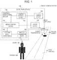
- FIG. 1is a block diagram illustrating a configuration of an object search system according to an embodiment.
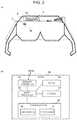
- FIG. 2is a block diagram illustrating a configuration of a scope according to the embodiment.
- FIG. 3is a diagram illustrating examples of a mode in which a straight line and a ripple for indicating a location of a fallen object are displayed in the embodiment.
- FIG. 4is a block diagram illustrating a configuration of the object search system according to the embodiment.
- the embodimentwill describe a technique of detecting an object in a vast area using the AR technique. Descriptions will be provided for an application example in which plant premises are searched for a fallen object by showing a specific display on a scope (object search device) including a transparent display.
- FIG. 1is a block diagram illustrating a schematic configuration of an object search system 1 according to the embodiment.
- FIG. 2is a diagram illustrating a scope 109 .
- FIG. 2( a )is a block diagram illustrating an example of a display to be shown on the scope 109 .
- FIG. 2( b )is a diagram illustrating a schematic configuration of the scope 109 .
- the object search system 1includes the scope 109 to be used by a worker 108 , and a detection device 110 .
- Information about a fallen object 106 which is detected by the detection device 110is shown on the scope 109 .
- the detection device 110includes: a radar device 100 ; a camera device 105 ; and a control/monitoring device 120 which controls the radar device 100 and the camera device 105 .
- a surface condition of a road surface 107is monitored using the radar device 100 and the camera device 105 to be installed within the premises. Where or how many radar devices 100 and camera devices 105 are to be installed is not particularly limited.
- Each radar device 100 and each camera device 105are connected to the detection device 110 using optical fibers and the like, and can be remotely controlled.
- the radar device 100detects the existence of the fallen object 106 by: transmitting a predetermined electromagnetic wave (for example, in a millimeter waveband with a frequency of 60 GHz or more); and receiving a wave reflected off the fallen object 106 . Based on a detection result, the camera device 105 takes an image of the fallen object 106 .
- a predetermined electromagnetic wavefor example, in a millimeter waveband with a frequency of 60 GHz or more
- the camera device 105takes an image of the fallen object 106 .
- the control/monitoring device 120includes a radar control device 101 , a detection result display device 102 , a wireless transmission device 103 , and a camera control device 104 .
- the radar control device 101controls the radar device 100 . Furthermore, the radar control device 101 has a function of performing signal processing on a signal reception processing result, and acquires fallen object information (specifically, position information (coordinates) and shape information) about the fallen object 106 by searching a predetermined range by the radar periodically or based on manipulation by an administrator or the like.
- fallen object informationspecifically, position information (coordinates) and shape information
- a camera control device 104takes an image of the detected fallen object 106 .
- the detection result display device 102displays the signal reception processing result obtained through the signal processing by the radar control device 101 . Specifically, the detection result display device 102 displays things such as: a map showing the position coordinates and fall position which are representative of where the fallen object 106 is; and a real image of the fallen object 106 which is taken by the camera device 105 .
- a wireless transmission device 103is connected to the detection result display device 102 , and transmits the fallen object information to portable terminals such as the scope 109 and a tablet (not illustrated) which the worker 108 carries.
- the transmission of the fallen object information to the scope 109 , the tablet and the likemay be preformed manually by the administrator who visually checks the existence of the fallen object 106 by looking at the detection result display device 102 , or may be performed automatically based on the information detected by the radar control device 101 .
- the scope 109includes a scope controller 151 , a wireless transmitter 152 , a display 153 , a storage 154 , and a position sensor 155 .
- the position sensor 155includes, for example, a GNSS sensor 156 and a gyro sensor 157 .
- the GNSS sensor 156detects a position of the scope 109 , that is to say, a position of the worker 108 .
- the gyro sensor 157detects a direction in which the scope 109 faces.
- the wireless transmitter 152acquires the fallen object information about the fallen object 106 and map information by making communications with the wireless transmission device 103 of the detection device 110 , and stores the fallen object information and the map information onto the storage 154 .
- the map informationmay be retained on the storage 154 in advance.
- the scope controller 151controls the entirety of the scope 109 .
- the scope controller 151compares a direction in which the worker 108 looks and the position of the fallen object based on the position information (coordinates) about the scope 109 acquired by the GNSS sensor 156 as well as the gyro sensor 157 , and displays a direction toward the fallen object 106 (that is to say, a direction in which the worker 108 is to go) on the display 153 using an arrow A.
- a distance to the fallen objectmay be indicated by changing boldness and length of the arrow A.
- the scope control 151displays a line B (which may be a straight line or a broken line) extending from upper to lower sides on the field of view like a rainfall, in the position of the fallen object 106 which is acquired from the detection device 110 . This display may blink. Furthermore, the distance between the fallen object 106 and the scope 109 may be displayed using a ripple C.
- FIG. 3illustrates an example of a mode in which the straight line B and the ripple C indicating the location of the fallen object 106 is displayed.
- a display example on a more leftward position in FIG. 3means being farther from the fallen object 106
- a display example on a more rightward position in FIG. 3means being nearer to the fallen object 106 .
- the displayis performed using an increased number of more ripples C in order for the worker 108 to visually realize that the worker 108 goes nearer to the fallen object 106 .
- a farthest fallen objectis displayed using a single ripple C, while a nearest fallen object is displayed using three ripples C.
- the image of the fallen object 106 taken by the camera device 105may be shown on the display 153 simultaneously. In this case, the image is displayed in an area where the image does not hinder the display of the fallen object 106 and the straight line B.
- Timings at which to search for the fallen object 106are not limited to daytime.
- the timingsmay be after dusk when there is a lack of sunshine.
- the scope 109displays things such as: the arrow A indicating the direction toward the fallen object 106 ; the line B extending from the upper to lower sides on the field of view like a rainfall which is displayed in the position of the fallen object 106 ; and the ripple C indicating the distance to the fallen object. The position of the fallen object, therefore, can be searched for by use of these displays.
- the radar control device 101acquires the position information about the fallen object 106 by identifying the position information from the detection information (S 12 ).
- the radar control device 101makes the camera device 105 take an image of the detected fallen object 106 by controlling the camera control device 104 , and causes the shape of the fallen object 106 to be checked (S 14 ).
- the detection result display device 102displays the fallen object 106 which is detected by the radar device 100 and whose image is taken by the camera device 105 (S 16 ), and transmits the object information about the fallen object 106 to the scope 109 (S 18 ).
- the scope 109performs the AR process on the object information about the fallen object 106 which is acquired from the detection device 110 and causes the display 153 to display the result (S 20 ).
- the worker 108can realizes specific information about the size, color and the like of the actual fallen object 106 . Accordingly, it is possible to achieve an easy search, and a reduction in the search time.
- FIG. 2( a ) and the likeshow an example of how the large fallen object 106 is detected.
- the use of the scope 109 according to the present inventionmakes it possible to reduce the labor and time to be required for the search to a large extent while securing the safety of the worker (a person engaging in the search).
- the scope 109includes the transparent type (optical transmission type) of display 153
- the scope 109may include a video transmission of display.
- the scope 109is provided with an image capturing device which acquires an image of the outside.
- the above-discussed embodimenthas provided the case where the scope 109 acquires the fallen object information (position information and the like) about the fallen object 106 by making the wireless communications with the detection device 110 .
- the method in which the object search device according to the present invention acquires the position information about the object from the outsideis not limited.
Landscapes
- Engineering & Computer Science (AREA)
- Physics & Mathematics (AREA)
- General Physics & Mathematics (AREA)
- Theoretical Computer Science (AREA)
- Multimedia (AREA)
- General Engineering & Computer Science (AREA)
- Astronomy & Astrophysics (AREA)
- Remote Sensing (AREA)
- Computer Graphics (AREA)
- Computer Hardware Design (AREA)
- Software Systems (AREA)
- Human Computer Interaction (AREA)
- User Interface Of Digital Computer (AREA)
- Traffic Control Systems (AREA)
- Controls And Circuits For Display Device (AREA)
Abstract
Description
Claims (6)
Applications Claiming Priority (4)
| Application Number | Priority Date | Filing Date | Title |
|---|---|---|---|
| JP2017184592 | 2017-09-26 | ||
| JP2017-184592 | 2017-09-26 | ||
| JPJP2017-184592 | 2017-09-26 | ||
| PCT/JP2018/031694WO2019065045A1 (en) | 2017-09-26 | 2018-08-28 | Object search system, object search device, and object search method |
Publications (2)
| Publication Number | Publication Date |
|---|---|
| US20200193159A1 US20200193159A1 (en) | 2020-06-18 |
| US11170221B2true US11170221B2 (en) | 2021-11-09 |
Family
ID=65901750
Family Applications (1)
| Application Number | Title | Priority Date | Filing Date |
|---|---|---|---|
| US16/642,828ActiveUS11170221B2 (en) | 2017-09-26 | 2018-08-28 | Object search system, object search device, and object search method |
Country Status (5)
| Country | Link |
|---|---|
| US (1) | US11170221B2 (en) |
| EP (1) | EP3690626B1 (en) |
| JP (1) | JP6859446B2 (en) |
| SG (1) | SG11202001936SA (en) |
| WO (1) | WO2019065045A1 (en) |
Cited By (9)
| Publication number | Priority date | Publication date | Assignee | Title |
|---|---|---|---|---|
| US20230080905A1 (en)* | 2021-09-15 | 2023-03-16 | Sony Interactive Entertainment Inc. | Dynamic notification surfacing in virtual or augmented reality scenes |
| US20230146384A1 (en)* | 2021-07-28 | 2023-05-11 | Multinarity Ltd | Initiating sensory prompts indicative of changes outside a field of view |
| US11924283B2 (en) | 2021-02-08 | 2024-03-05 | Multinarity Ltd | Moving content between virtual and physical displays |
| US11948263B1 (en) | 2023-03-14 | 2024-04-02 | Sightful Computers Ltd | Recording the complete physical and extended reality environments of a user |
| US12073054B2 (en) | 2022-09-30 | 2024-08-27 | Sightful Computers Ltd | Managing virtual collisions between moving virtual objects |
| US12094070B2 (en) | 2021-02-08 | 2024-09-17 | Sightful Computers Ltd | Coordinating cursor movement between a physical surface and a virtual surface |
| US12175614B2 (en) | 2022-01-25 | 2024-12-24 | Sightful Computers Ltd | Recording the complete physical and extended reality environments of a user |
| US12189422B2 (en) | 2021-02-08 | 2025-01-07 | Sightful Computers Ltd | Extending working display beyond screen edges |
| US12380238B2 (en) | 2022-01-25 | 2025-08-05 | Sightful Computers Ltd | Dual mode presentation of user interface elements |
Families Citing this family (3)
| Publication number | Priority date | Publication date | Assignee | Title |
|---|---|---|---|---|
| US11107360B1 (en)* | 2019-08-28 | 2021-08-31 | Amazon Technologies, Inc. | Automated air traffic control systems and methods |
| US11611651B2 (en)* | 2021-07-09 | 2023-03-21 | Kawasaki Motors, Ltd. | Calling system and method for personal watercraft |
| WO2023026451A1 (en)* | 2021-08-27 | 2023-03-02 | 株式会社日立国際電気 | Object search system, object search device, object search method |
Citations (14)
| Publication number | Priority date | Publication date | Assignee | Title |
|---|---|---|---|---|
| JP2005275723A (en) | 2004-03-24 | 2005-10-06 | Mitsubishi Electric Corp | Surveillance moving body, foreign object detection sensor and road surface maintenance management system |
| JP2009052907A (en) | 2007-08-23 | 2009-03-12 | Kozo Keikaku Engineering Inc | Foreign matter detecting system |
| US20090243881A1 (en) | 2008-03-31 | 2009-10-01 | Xsight Systems Ltd. | System and method for ascription of foreign object debris detected on airport travel surfaces to foreign object sources |
| JP2010004381A (en) | 2008-06-20 | 2010-01-07 | Olympus Corp | Personal digital assistant |
| JP2011242591A (en) | 2010-05-18 | 2011-12-01 | Fujifilm Corp | Head-mounted display device |
| JP2012095914A (en) | 2010-11-04 | 2012-05-24 | Ns Solutions Corp | Golf player support system, user terminal device, method of supporting golf player, and program |
| JP2012251900A (en) | 2011-06-03 | 2012-12-20 | Ihi Corp | Leftover object detecting method and device |
| US20130172093A1 (en) | 2011-12-30 | 2013-07-04 | Nike, Inc. | System For Tracking A Golf Ball And Displaying An Enhanced Image Of The Golf Ball |
| US20140055491A1 (en) | 2012-08-27 | 2014-02-27 | Empire Technology Development Llc | Indicating the geographic origin of a digitally-mediated communication |
| WO2014170895A1 (en) | 2013-04-15 | 2014-10-23 | Xsight Systems Ltd. | Contaminant detection and bird risk management at airports |
| US20140354684A1 (en)* | 2013-05-28 | 2014-12-04 | Honda Motor Co., Ltd. | Symbology system and augmented reality heads up display (hud) for communicating safety information |
| JP2015075832A (en) | 2013-10-07 | 2015-04-20 | コニカミノルタ株式会社 | Ar display system, ar display device, information processor, and program |
| US20160078278A1 (en)* | 2014-09-17 | 2016-03-17 | Toyota Motor Engineering & Manufacturing North America, Inc. | Wearable eyeglasses for providing social and environmental awareness |
| JP2016172469A (en) | 2015-03-16 | 2016-09-29 | 株式会社デンソー | Image generation device |
Family Cites Families (3)
| Publication number | Priority date | Publication date | Assignee | Title |
|---|---|---|---|---|
| JP2011248765A (en)* | 2010-05-28 | 2011-12-08 | Sony Corp | Information processing device, information processing system and program |
| WO2014069442A1 (en)* | 2012-10-31 | 2014-05-08 | 日本電気株式会社 | Ripple user interface for information display system |
| JP2015162152A (en)* | 2014-02-28 | 2015-09-07 | 京セラドキュメントソリューションズ株式会社 | Touch panel device and image forming apparatus |
- 2018
- 2018-08-28USUS16/642,828patent/US11170221B2/enactiveActive
- 2018-08-28EPEP18860092.8Apatent/EP3690626B1/enactiveActive
- 2018-08-28JPJP2019544442Apatent/JP6859446B2/enactiveActive
- 2018-08-28SGSG11202001936SApatent/SG11202001936SA/enunknown
- 2018-08-28WOPCT/JP2018/031694patent/WO2019065045A1/ennot_activeCeased
Patent Citations (18)
| Publication number | Priority date | Publication date | Assignee | Title |
|---|---|---|---|---|
| JP2005275723A (en) | 2004-03-24 | 2005-10-06 | Mitsubishi Electric Corp | Surveillance moving body, foreign object detection sensor and road surface maintenance management system |
| JP2009052907A (en) | 2007-08-23 | 2009-03-12 | Kozo Keikaku Engineering Inc | Foreign matter detecting system |
| US20090243881A1 (en) | 2008-03-31 | 2009-10-01 | Xsight Systems Ltd. | System and method for ascription of foreign object debris detected on airport travel surfaces to foreign object sources |
| JP2010004381A (en) | 2008-06-20 | 2010-01-07 | Olympus Corp | Personal digital assistant |
| JP2011242591A (en) | 2010-05-18 | 2011-12-01 | Fujifilm Corp | Head-mounted display device |
| JP5603205B2 (en) | 2010-11-04 | 2014-10-08 | 新日鉄住金ソリューションズ株式会社 | Golf player support system, user terminal device, golf player support method and program |
| JP2012095914A (en) | 2010-11-04 | 2012-05-24 | Ns Solutions Corp | Golf player support system, user terminal device, method of supporting golf player, and program |
| JP2012251900A (en) | 2011-06-03 | 2012-12-20 | Ihi Corp | Leftover object detecting method and device |
| JP2015503399A (en) | 2011-12-30 | 2015-02-02 | ナイキ イノヴェイト シーヴィー | System for tracking a golf ball and displaying an enhanced image of the golf ball |
| US20130172093A1 (en) | 2011-12-30 | 2013-07-04 | Nike, Inc. | System For Tracking A Golf Ball And Displaying An Enhanced Image Of The Golf Ball |
| US20140055491A1 (en) | 2012-08-27 | 2014-02-27 | Empire Technology Development Llc | Indicating the geographic origin of a digitally-mediated communication |
| JP2015537264A (en) | 2012-08-27 | 2015-12-24 | エンパイア テクノロジー ディベロップメント エルエルシー | Indicate the geographical source of digitally mediated communications |
| WO2014170895A1 (en) | 2013-04-15 | 2014-10-23 | Xsight Systems Ltd. | Contaminant detection and bird risk management at airports |
| US20140354684A1 (en)* | 2013-05-28 | 2014-12-04 | Honda Motor Co., Ltd. | Symbology system and augmented reality heads up display (hud) for communicating safety information |
| JP2015075832A (en) | 2013-10-07 | 2015-04-20 | コニカミノルタ株式会社 | Ar display system, ar display device, information processor, and program |
| US20160078278A1 (en)* | 2014-09-17 | 2016-03-17 | Toyota Motor Engineering & Manufacturing North America, Inc. | Wearable eyeglasses for providing social and environmental awareness |
| JP2016172469A (en) | 2015-03-16 | 2016-09-29 | 株式会社デンソー | Image generation device |
| US20180090007A1 (en)* | 2015-03-16 | 2018-03-29 | Denso Corporation | Image generation apparatus |
Non-Patent Citations (3)
| Title |
|---|
| International Search Report (English and Japanese) issued in PCT/JP2018/031694, dated Oct. 30, 2018; ISA/JP. |
| Nobata, Yoshinori et al., "Foreign object debris detection stem using W-band millimeter signal", Proceedings of the Engineering Sciences Society Conference of IEICE 2013; Sep. 3, 2013, C-14-14, p. 259. |
| Search Report and Written Opinion dated May 18, 2021 in corresponding Singapore application No. 11202001936S. |
Cited By (22)
| Publication number | Priority date | Publication date | Assignee | Title |
|---|---|---|---|---|
| US12095867B2 (en) | 2021-02-08 | 2024-09-17 | Sightful Computers Ltd | Shared extended reality coordinate system generated on-the-fly |
| US11924283B2 (en) | 2021-02-08 | 2024-03-05 | Multinarity Ltd | Moving content between virtual and physical displays |
| US12360558B2 (en) | 2021-02-08 | 2025-07-15 | Sightful Computers Ltd | Altering display of virtual content based on mobility status change |
| US12360557B2 (en) | 2021-02-08 | 2025-07-15 | Sightful Computers Ltd | Docking virtual objects to surfaces |
| US12094070B2 (en) | 2021-02-08 | 2024-09-17 | Sightful Computers Ltd | Coordinating cursor movement between a physical surface and a virtual surface |
| US12095866B2 (en) | 2021-02-08 | 2024-09-17 | Multinarity Ltd | Sharing obscured content to provide situational awareness |
| US12189422B2 (en) | 2021-02-08 | 2025-01-07 | Sightful Computers Ltd | Extending working display beyond screen edges |
| US20230146384A1 (en)* | 2021-07-28 | 2023-05-11 | Multinarity Ltd | Initiating sensory prompts indicative of changes outside a field of view |
| US11829524B2 (en) | 2021-07-28 | 2023-11-28 | Multinarity Ltd. | Moving content between a virtual display and an extended reality environment |
| US12265655B2 (en) | 2021-07-28 | 2025-04-01 | Sightful Computers Ltd. | Moving windows between a virtual display and an extended reality environment |
| US12236008B2 (en) | 2021-07-28 | 2025-02-25 | Sightful Computers Ltd | Enhancing physical notebooks in extended reality |
| US11874959B2 (en)* | 2021-09-15 | 2024-01-16 | Sony Interactive Entertainment Inc. | Dynamic notification surfacing in virtual or augmented reality scenes |
| US20230080905A1 (en)* | 2021-09-15 | 2023-03-16 | Sony Interactive Entertainment Inc. | Dynamic notification surfacing in virtual or augmented reality scenes |
| US12175614B2 (en) | 2022-01-25 | 2024-12-24 | Sightful Computers Ltd | Recording the complete physical and extended reality environments of a user |
| US12380238B2 (en) | 2022-01-25 | 2025-08-05 | Sightful Computers Ltd | Dual mode presentation of user interface elements |
| US12141416B2 (en) | 2022-09-30 | 2024-11-12 | Sightful Computers Ltd | Protocol for facilitating presentation of extended reality content in different physical environments |
| US12124675B2 (en) | 2022-09-30 | 2024-10-22 | Sightful Computers Ltd | Location-based virtual resource locator |
| US12112012B2 (en) | 2022-09-30 | 2024-10-08 | Sightful Computers Ltd | User-customized location based content presentation |
| US12099696B2 (en) | 2022-09-30 | 2024-09-24 | Sightful Computers Ltd | Displaying virtual content on moving vehicles |
| US12079442B2 (en) | 2022-09-30 | 2024-09-03 | Sightful Computers Ltd | Presenting extended reality content in different physical environments |
| US12073054B2 (en) | 2022-09-30 | 2024-08-27 | Sightful Computers Ltd | Managing virtual collisions between moving virtual objects |
| US11948263B1 (en) | 2023-03-14 | 2024-04-02 | Sightful Computers Ltd | Recording the complete physical and extended reality environments of a user |
Also Published As
| Publication number | Publication date |
|---|---|
| JP6859446B2 (en) | 2021-04-14 |
| JPWO2019065045A1 (en) | 2020-04-23 |
| EP3690626A4 (en) | 2021-06-23 |
| EP3690626A1 (en) | 2020-08-05 |
| US20200193159A1 (en) | 2020-06-18 |
| SG11202001936SA (en) | 2020-04-29 |
| EP3690626B1 (en) | 2024-02-07 |
| WO2019065045A1 (en) | 2019-04-04 |
Similar Documents
| Publication | Publication Date | Title |
|---|---|---|
| US11170221B2 (en) | Object search system, object search device, and object search method | |
| CN115597659B (en) | Intelligent safety management and control method for transformer substation | |
| KR101747180B1 (en) | Auto video surveillance system and method | |
| KR101727162B1 (en) | Apparatus and method for providing vessel traffic service | |
| WO2021159549A1 (en) | Road condition sensing and evaluation method for traffic safety | |
| CN109373821A (en) | Anti- unmanned machine equipment, system and method | |
| CN107422390A (en) | A kind of airfield pavement foreign body intelligent detecting and purging system | |
| EP3064899A1 (en) | Tracking in an indoor environment | |
| US20190299412A1 (en) | Augmented Reality System | |
| KR101379636B1 (en) | Automatic identification system and method for ship by using image of monocular camera vision | |
| WO2017169841A1 (en) | Display device and display control method | |
| US9979934B1 (en) | Automated weather sensing system and method using cameras | |
| KR101910887B1 (en) | Method of displaying the location of the foreign substance within the runway | |
| KR101496446B1 (en) | System for managing of Submarine Cable Using by Recognization Radio Frequency and Method Thereof | |
| US9282230B2 (en) | Automatic tracking camera system | |
| CN102311076A (en) | Patrol robot and production method thereof | |
| CN202297053U (en) | Patrolling robot | |
| RU155323U1 (en) | UNMANNED AIRCRAFT CONTROL SYSTEM | |
| CN111010543B (en) | Robot remote-viewing video monitoring method and device, electronic equipment and storage medium | |
| KR101501022B1 (en) | System and method for providing a navaids data | |
| JP2000152220A (en) | Method for controlling monitor itv camera | |
| KR20230094466A (en) | System and method for monitoring operator | |
| RU2563557C2 (en) | Multispectral system and method for electro-optical surveillance of protected area | |
| CN205384519U (en) | Device that aims is trailed in infrared thermal imaging search | |
| KR102683516B1 (en) | Surveillance camera system including Augmented Reality mobile device and the control method thereof |
Legal Events
| Date | Code | Title | Description |
|---|---|---|---|
| AS | Assignment | Owner name:HITACHI KOKUSAI ELECTRIC INC., JAPAN Free format text:ASSIGNMENT OF ASSIGNORS INTEREST;ASSIGNORS:SATO, YOSUKE;KASHIMA, KENICHI;REEL/FRAME:052046/0958 Effective date:20200130 | |
| FEPP | Fee payment procedure | Free format text:ENTITY STATUS SET TO UNDISCOUNTED (ORIGINAL EVENT CODE: BIG.); ENTITY STATUS OF PATENT OWNER: LARGE ENTITY | |
| STPP | Information on status: patent application and granting procedure in general | Free format text:NON FINAL ACTION MAILED | |
| STPP | Information on status: patent application and granting procedure in general | Free format text:RESPONSE TO NON-FINAL OFFICE ACTION ENTERED AND FORWARDED TO EXAMINER | |
| STPP | Information on status: patent application and granting procedure in general | Free format text:FINAL REJECTION MAILED | |
| STPP | Information on status: patent application and granting procedure in general | Free format text:DOCKETED NEW CASE - READY FOR EXAMINATION | |
| STPP | Information on status: patent application and granting procedure in general | Free format text:NOTICE OF ALLOWANCE MAILED -- APPLICATION RECEIVED IN OFFICE OF PUBLICATIONS | |
| STPP | Information on status: patent application and granting procedure in general | Free format text:AWAITING TC RESP., ISSUE FEE NOT PAID | |
| STPP | Information on status: patent application and granting procedure in general | Free format text:NOTICE OF ALLOWANCE MAILED -- APPLICATION RECEIVED IN OFFICE OF PUBLICATIONS | |
| STPP | Information on status: patent application and granting procedure in general | Free format text:PUBLICATIONS -- ISSUE FEE PAYMENT VERIFIED | |
| STCF | Information on status: patent grant | Free format text:PATENTED CASE | |
| MAFP | Maintenance fee payment | Free format text:PAYMENT OF MAINTENANCE FEE, 4TH YEAR, LARGE ENTITY (ORIGINAL EVENT CODE: M1551); ENTITY STATUS OF PATENT OWNER: LARGE ENTITY Year of fee payment:4 | |
| AS | Assignment | Owner name:KOKUSAI DENKI ELECTRIC INC., JAPAN Free format text:CHANGE OF NAME;ASSIGNOR:HITACHI KOKUSAI ELECTRIC INC.;REEL/FRAME:071275/0236 Effective date:20241227 Owner name:HITACHI KOKUSAI ELECTRIC INC., JAPAN Free format text:CHANGE OF ADDRESS;ASSIGNOR:HITACHI KOKUSAI ELECTRIC INC.;REEL/FRAME:071275/0058 Effective date:20161001 |