US11169344B2 - Common module storage within a fiber distribution hub - Google Patents
Common module storage within a fiber distribution hubDownload PDFInfo
- Publication number
- US11169344B2 US11169344B2US16/286,791US201916286791AUS11169344B2US 11169344 B2US11169344 B2US 11169344B2US 201916286791 AUS201916286791 AUS 201916286791AUS 11169344 B2US11169344 B2US 11169344B2
- Authority
- US
- United States
- Prior art keywords
- connector
- storage module
- module
- fiber optic
- connector holder
- Prior art date
- Legal status (The legal status is an assumption and is not a legal conclusion. Google has not performed a legal analysis and makes no representation as to the accuracy of the status listed.)
- Active
Links
Images


Classifications
- G—PHYSICS
- G02—OPTICS
- G02B—OPTICAL ELEMENTS, SYSTEMS OR APPARATUS
- G02B6/00—Light guides; Structural details of arrangements comprising light guides and other optical elements, e.g. couplings
- G02B6/44—Mechanical structures for providing tensile strength and external protection for fibres, e.g. optical transmission cables
- G02B6/4439—Auxiliary devices
- G02B6/444—Systems or boxes with surplus lengths
- G02B6/4452—Distribution frames
- G—PHYSICS
- G02—OPTICS
- G02B—OPTICAL ELEMENTS, SYSTEMS OR APPARATUS
- G02B6/00—Light guides; Structural details of arrangements comprising light guides and other optical elements, e.g. couplings
- G02B6/44—Mechanical structures for providing tensile strength and external protection for fibres, e.g. optical transmission cables
- G02B6/4439—Auxiliary devices
- G02B6/444—Systems or boxes with surplus lengths
- G02B6/44528—Patch-cords; Connector arrangements in the system or in the box
- G—PHYSICS
- G02—OPTICS
- G02B—OPTICAL ELEMENTS, SYSTEMS OR APPARATUS
- G02B6/00—Light guides; Structural details of arrangements comprising light guides and other optical elements, e.g. couplings
- G02B6/24—Coupling light guides
- G02B6/36—Mechanical coupling means
- G02B6/38—Mechanical coupling means having fibre to fibre mating means
- G02B6/3807—Dismountable connectors, i.e. comprising plugs
- G02B6/3897—Connectors fixed to housings, casing, frames or circuit boards
- G—PHYSICS
- G02—OPTICS
- G02B—OPTICAL ELEMENTS, SYSTEMS OR APPARATUS
- G02B6/00—Light guides; Structural details of arrangements comprising light guides and other optical elements, e.g. couplings
- G02B6/44—Mechanical structures for providing tensile strength and external protection for fibres, e.g. optical transmission cables
- G02B6/4439—Auxiliary devices
- G02B6/444—Systems or boxes with surplus lengths
- G02B6/4441—Boxes
- G02B6/4442—Cap coupling boxes
- G—PHYSICS
- G02—OPTICS
- G02B—OPTICAL ELEMENTS, SYSTEMS OR APPARATUS
- G02B6/00—Light guides; Structural details of arrangements comprising light guides and other optical elements, e.g. couplings
- G02B6/44—Mechanical structures for providing tensile strength and external protection for fibres, e.g. optical transmission cables
- G02B6/4439—Auxiliary devices
- G02B6/444—Systems or boxes with surplus lengths
- G02B6/4441—Boxes
- G02B6/4446—Cable boxes, e.g. splicing boxes with two or more multi fibre cables
- G02B6/44465—Seals
- G—PHYSICS
- G02—OPTICS
- G02B—OPTICAL ELEMENTS, SYSTEMS OR APPARATUS
- G02B6/00—Light guides; Structural details of arrangements comprising light guides and other optical elements, e.g. couplings
- G02B6/44—Mechanical structures for providing tensile strength and external protection for fibres, e.g. optical transmission cables
- G02B6/4439—Auxiliary devices
- G02B6/444—Systems or boxes with surplus lengths
- G02B6/4452—Distribution frames
- G02B6/44524—Distribution frames with frame parts or auxiliary devices mounted on the frame and collectively not covering a whole width of the frame or rack
Definitions
- Passive optical networksare becoming prevalent in part because service providers want to deliver high bandwidth communication capabilities to customers. Passive optical networks are a desirable choice for delivering high-speed communication data because they may not employ active electronic devices, such as amplifiers and repeaters, between a central office and a subscriber termination. The absence of active electronic devices may decrease network complexity and/or cost and may increase network reliability.
- FIG. 1illustrates a network 100 deploying passive fiber optic lines.
- the network 100can include a central office 101 that connects a number of end subscribers 105 (also called end users 105 herein) in a network.
- the central office 110can additionally connect to a larger network such as the Internet (not shown) and a public switched telephone network (PSTN).
- PSTNpublic switched telephone network
- the network 100can also include fiber distribution hubs 130 having one or more optical splitters (e.g., 1-to-8 splitters, 1-to-16 splitters, or 1-to-32 splitters) that generate a number of individual fibers that may lead to the premises of an end user 115 .
- the various lines of the network 100can be aerial or housed within underground conduits.
- the portion of the network 100 that is closest to central office 110is generally referred to as the F1 region, where F1 is the “feeder fiber” from the central office 110 .
- the portion of the network 100 closest to the end users 105can be referred to as an F2 portion of network 100 .
- the network 100includes a plurality of break-out locations 125 at which branch cables 105 are separated out from the main cable lines 120 .
- Branch cables 105are often connected to drop terminals 104 that include connector interfaces for facilitating coupling of the fibers of the branch cables to a plurality of different subscriber locations 115 .
- Splitters used in an fiber distribution hub 130can accept a feeder cable F1 having a number of fibers and may split those incoming fibers into, for example, 216 to 432 individual distribution fibers that may be associated with a like number of end user locations.
- an optical splitteris provided prepackaged in an optical splitter module housing and provided with a splitter output in pigtails that extend from the module.
- the splitter output pigtailsare typically connectorized with, for example, SC, LC, or LX.5 connectors.
- the optical splitter moduleprovides protective packaging for the optical splitter components in the housing and thus provides for easy handling for otherwise fragile splitter components. This modular approach allows optical splitter modules to be added incrementally to fiber distribution hubs 130 as required.
- Splitter pigtailscan be stored at a connector holder location until service is desired.
- Example pigtail storage used in a fiber distribution hub 130is disclosed in U.S. Pat. No. 7,218,827. Improvements are desired.
- Some aspects of the disclosureare directed to a fiber distribution hub including a fiber termination field and a module mounting location separate from the fiber termination field.
- the fiber termination fieldincludes a plurality of optical adapters that act as a transition point between incoming and outgoing cables within the fiber distribution hub.
- One or more modules of various typescan be mounted at the module mounting location.
- Non-limiting examples of module typesinclude a splitter module, a connector storage module, and a fiber storage module.
- a splitter moduleincludes an optical splitter disposed within a body having an input and an output.
- the optical splittersplits optical signals received at the input onto pigtails extending through the output.
- the pigtailshave ends terminated at fiber optic connectors.
- dust capsare mounted over end faces of the fiber optic connectors.
- a connector storage moduleincludes a body having a plurality of connector holder stations. Each connector holder station is configured to retain a fiber optic connector. In certain examples, each connector holder station retains a fiber optic connector with a dust cap mounted over the end face of the fiber optic connector. In certain examples, the connector storage module does not include an optical splitter. In certain examples, the connector holder stations are accessed laterally through a first side of the body while fibers (e.g., splitter pigtails) terminated by the fiber optic connectors extend through a front of the body. In an example, a cover mounts to the first side of the body to block access to the fiber optic connectors retained at the connector holder stations. In certain examples, the connector holder station includes a cable manager for holding excess length of the optical fibers terminated by the fiber optic connectors.
- a fiber storage moduleincludes a body in which a plurality of optical fibers (e.g., splitter pigtails) may be stored.
- the bodymay define a spool or a plurality of bend radius limiters about which the optical fibers may be routed.
- a coil or other section of the optical fibersare inserted into the body through a first side of the body while the optical fibers extend out of the body through a front of the body.
- the fiber storage moduledoes not include an optical splitter.
- the fiber storage moduledoes not include a connector holder station.
- the module mounting locationdefines a plurality of module mounting spaces (e.g., slots) at which the various modules can be mounted in any desired order.
- a splitter modulecan be mounted next to a connector storage module or next to a fiber storage module or next to another splitter module.
- the various moduleshave a common footprint so that any of the modules can fit at any of the module mounting spaces.
- the various modulesare each sized to interchangeably fit at any of the module mounting spaces.
- each of the various modulesis configured to secure to (e.g., latch to, fasten to, friction-fit within etc.) one of the module mounting spaces.
- inventive aspectscan relate to individual features and to combinations of features. It is to be understood that both the forgoing general description and the following detailed description are exemplary and explanatory only and are not restrictive of the broad inventive concepts upon which the embodiments disclosed herein are based.
- FIG. 1shows a passive fiber optic network
- FIG. 2is a schematic diagram of an example fiber distribution hub including a module mounting location and a termination field;
- FIG. 3is a schematic diagram of an example splitter module suitable for mounting at the module mounting location of the fiber distribution hub of FIG. 2 ;
- FIG. 4is a schematic diagram of an example connector storage module suitable for mounting at the module mounting location of the fiber distribution hub of FIG. 2 ;
- FIG. 5is a perspective view of the connector storage module of FIG. 4 ;
- FIG. 6is a schematic diagram of an example fiber storage module suitable for mounting at the module mounting location of the fiber distribution hub of FIG. 2 .
- the present disclosureis directed to a fiber distribution hub including a fiber termination field and a module mounting location separate from the fiber termination field.
- the fiber termination fieldincludes a plurality of optical adapters that act as a transition point between incoming and outgoing cables within the fiber distribution hub.
- the module mounting locationdefines a plurality of module mounting spaces (e.g., slots) at which the various modules can be mounted in any desired order.
- modules of various typescan be mounted at the module mounting location.
- module typesinclude a splitter module, a connector storage module, and a fiber storage module.
- a splitter modulecan be mounted next to a connector storage module or next to a fiber storage module or next to another splitter module.
- the various moduleshave a common footprint so that any of the modules can fit at any of the module mounting spaces.
- the various modulesare each sized to interchangeably fit at any of the module mounting spaces.
- each of the various modulesis configured to secure to (e.g., latch to, fasten to, friction-fit within etc.) one of the module mounting spaces.
- a fiber distribution hub 200includes a cabinet 202 defining an interior.
- a termination field 240 and a module mounting location 220are disposed within the interior of the cabinet 202 .
- the termination field 240includes optical adapters 245 having opposite first and second ports. The first ports face out from a first side of the termination field 240 and the second ports face out from a second side of the termination field 240 .
- the termination field 240is mounted to a swing frame chassis 204 .
- the cabinet 202also includes a cable port 210 through which one or more input cables 281 and one or more output cables 288 enter the cabinet 202 .
- the cable port 210is sealed (e.g., by a cable gland).
- the cable port 210is a ruggedized connectorized interface at which a feeder cable and a distribution cable can be optically connected to an internal input cable 281 and an internal output cable 288 , respectively.
- the input and output cables 281 , 288(or feeder and distribution cables) are anchored to the cabinet 202 at an anchor point 212 .
- the cables 281 , 288are clamped to the cabinet 202 at the anchor point 212 .
- the termination field 240defines the connection point between the incoming cables 281 and the outgoing cables 288 .
- the second ports of the optical adapters 245 at the termination field 240are pre-cabled to connect to the outgoing cable 288 .
- fibers 286have first ends terminated at fiber optic connectors 287 plugged into the second ports of the adapters 245 and second ends routed to a cable interface location 216 at which an interface arrangement 217 is disposed.
- the cable interface arrangement 217includes one or more splice trays at which the second ends of the fibers 286 are spliced to the outgoing cable 288 .
- the cable interface arrangement 217includes one or more optical adapters at which connectorized ends of the fibers 286 connect to connectorized ends of the outgoing cable 288 .
- connectorized ends of the outgoing cable 288can be routed directly to the second ports of the adapters 245 at the termination field 240 .
- connectorized ends of the incoming cable 281can be routed directly to the module mounting location 220 . In other implementations, however, the end of the incoming cable 281 is routed to a cable interface location 214 at which an interface arrangement 215 is disposed.
- the cable interface arrangement 215includes one or more splice trays at which the incoming cable 281 is spliced to module input fibers 282 . In other examples, the cable interface arrangement 215 includes one or more optical adapters at which connectorized ends of the incoming cable 281 connect to connectorized ends of the module input fibers 282 .
- the module mounting location 220is disposed within the cabinet 202 separate from the termination field 240 . In certain examples, the module mounting location 220 also is mounted to a swing frame chassis. In an example, the module mounting location 220 is mounted to the same swing frame chassis 204 as the termination field 240 . In some examples, the module mounting location 220 is disposed above the termination field 240 . In other examples, the module mounting location 220 is disposed beneath the termination field 240 . In still other examples, the module mounting location 220 is disposed side-by-side with the termination field 240 .
- the module mounting location 220includes a plurality of mounting spaces 225 .
- Each mounting space 225is configured to receive one of a variety of types of modules.
- each space 225can interchangeably receive a splitter module 230 , a fiber storage module 250 , a connector storage module 260 , or a pass-through module.
- Certain types of modulesmay take up more than one space 225 .
- a connector holder module 260 configured to hold SC connectorsmay take up two spaces 225 whereas a connector holder module 260 configured to hold LC connectors may take up a single space 225 .
- the module mounting location 220includes a row of spaces 225 extending horizontally within the cabinet 202 . In other implementations, the module mounting location 220 includes a column of spaces 225 so that the modules received thereat are stacked vertically. In some examples, the spaces 225 in the form of slots in which the modules are received. In certain examples, walls or partial walls may separate the slots 225 . In other examples, the spaces 225 include a row or column of guide channels along which portions of the modules can slide. In certain examples, each space 225 has a retaining structure that secures the module at a fixed position in the space 225 . For example, each space 225 can have a latch feature or fastener aperture that aligns with a latch feature or fastener aperture on the module.
- modulescan be mounted at the spaces 225 .
- Modulesalso can be referred to as cartridges, cassettes, trays, housings, devices, or components.
- suitable modulesinclude a splitter module 230 , a fiber/cable storage module 250 , a connector holder module 260 , and a pass-through module.
- splitter modules 230house optical splitters that split signals received at splitter inputs onto splitter pigtails.
- a pass-through modulemay directly connect a connectorized pigtail to an input cable 281 or module input fiber 282 without splitting the signal.
- a pass-through modulemay fanout a multi-fiber input cable 281 or multi-fiber module input cable 282 into a plurality of separate connectorized pigtails 235 without splitting the optical signals.
- Connector holder modules 260store optical connectors within the modules.
- Fiber/cable storage modulesstore optical fiber or cables (e.g., excess length of pigtails) within the modules.
- one or more modulescan be tethered together prior to installation at the cabinet 202 .
- Tethered modulesare movable relative to each other.
- Tethered modulescan be installed at separate locations within the cabinet 202 .
- Tethered modulesare installed at the cabinet during the same general timeframe, but need not be loaded simultaneously.
- tether modulesalso can be installed at the cabinet as a unit.
- one or more splitter modules 230 and one or more connector storage modules 260can be installed in the cabinet 202 at the module mounting location 220 at generally the same time.
- a splitter module 230can be installed at a first space 225 in the module mounting location 220 and one or more connector storage modules 260 can be installed at one or more additional spaces 225 .
- Either module 230 , 260can be installed before the other.
- Each module 230 , 260is separately secured (e.g., latched, fastened, etc.) at the respective space 225 .
- the connectorized ends 237 of the splitter pigtails 235 output from the splitter 230are retained at the one or more connector storage modules 260 .
- a splitter module 230 , a fiber/cable storage module 250 , and a connector storage module 260can all be tethered together.
- the fiber/cable storage module 250may be positioned between the splitter module 230 and the connector storage module 260 .
- the fiber/cable storage module 250holds the excess length of the pigtails 235 between the splitter module 230 and the connector storage module 260 .
- each of the modules 230 , 250 , 260is movable relative to the other modules.
- each of the modules 230 , 250 , 260is separately loadable at different spaces 225 at the module mounting location 220 .
- the connectorized ends 237 of the splitter pigtails 235are removed from the connector storage module 260 .
- the connector storage module 260is removed from the respective space 225 before the connectorized ends 237 are removed from the connector storage module 260 .
- the connectorized ends 237cannot be removed from the connector storage module 260 while the connector storage module 260 is disposed at any of the spaces 225 of the module mounting location 220 .
- the pigtails 235are removed from the fiber storage module 260 .
- the splitter pigtails 235are routed from the splitter module 230 , along a fiber routing path 270 , to the termination field 240 .
- Connectorized ends 237 of the pigtails 235are plugged into first ports of the optical adapters 245 at the termination field 240 .
- Excess length of the pigtails 235can be taken up by cable managers 275 (e.g., spools, half spools, bend radius limiters, clips, ties, etc.) along the fiber routing path 270 .
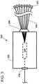
- FIG. 3shows an example splitter module 230 suitable for use with the cabinet of FIG. 2 .
- the example splitter module 230includes a body 232 housing an optical splitter 234 .
- the body 232defines an input 236 and an output 238 .
- the optical splitter 234splits an optical signal received at the input 236 onto a plurality of pigtails 235 that extend through the output 238 .
- ends of the pigtailsare connectorized with fiber optic connectors 237 .
- the input 236includes a port configured to receive a fiber optic connector terminating an end of an input cable 281 or module input fiber 282 .
- the input 236includes a connectorized stub fiber that can be routed to the first cable interface arrangement 215 .
- the output 238includes a strain relief boot extending outwardly from the housing 232 through which the pigtails 235 extend.
- the output 238can include a multi-fiber cable port or a plurality of single-fiber cable ports.
- FIGS. 4 and 5shows an example connector storage module 260 suitable for use with the cabinet of FIG. 2 and/or splitter module of FIG. 3 .
- the connector storage module 260includes a body 261 having a depth D extending between a front (or cable entry end) 262 and a rear 263 , a width W extending between opposite first and second sides 264 , 266 , and a height H extending between a top and a bottom of the body 261 to define an interior 269 .
- the connector storage module 260does not include an optical splitter.
- One or more connector holder stations 265are carried by the body 261 .
- Connectorized ends of fibers or cablese.g., connectorized ends 237 of pigtails 235
- the connector holder stations 265hold onto fiber optic connectors terminating the ends of the fibers or cables.
- the connector holder stations 265hold onto bodies of the fiber optic connectors.
- the connector holder stations 265hold onto ferrules of the fiber optic connectors.
- the connector holder stations 265hold onto strain-relief of the fiber optic connectors.
- the connector holder stations 265hold onto the fibers or cables adjacent the fiber optic connectors.
- the connector holder stations 265hold onto the dust caps covering the optical end faces of the fiber optic connectors.
- the connector holder stations 265retain the fiber optic connectors with dust caps covering optical end faces (e.g., ferrule end faces) of the fiber optic connectors.
- the connector holder stations 265include integral dust caps that cover the optical end faces of the fiber optic connectors mounted at the connector holder stations 265 .
- the connector holder stations 265are disposed within the interior 269 of the body 261 .
- the connector holder station 260includes a plurality of connector holder stations 265 layered along the depth of the body 261 .
- a first connector holder station 265is disposed at a first location along the depth and a second connector holder station 265 is disposed at a second location along the depth, the second location being different from the first location.
- the connector holder stations 265are staggered between the front 262 and rear 263 of the connector storage module 260 .
- a plurality of the connector holder stations 265are spaced at different distances from the cable entry end 262 of the connector storage module 260 .
- first and second connector holder stations 265are offset from each other along the height of the body 261 . In other examples, the first and second connector holder stations 265 are aligned at a common height. In certain implementations, the connector holder stations 265 overlap along the height of the connector storage module 260 .
- the plurality of the connector holder stations 265are spaced at different distances from the cable entry end 262 and the connector holder stations 265 overlap each other along the height of the connector storage module 265 .
- the connector holder module 260can store more connectors than could fit within the surface area formed by the height and width of the connector holder module 260 .
- the body 261includes at least four connector holder stations 265 . In certain implementations, the body 261 includes at least six connector holder stations 265 . In certain implementations, the body 261 includes at least eight connector holder stations 265 . In certain implementations, the body 261 includes at least twelve connector holder stations 265 . In certain implementations, the body 261 includes at least sixteen connector holder stations 265 . In certain implementations, the body 261 includes between four and sixteen connector holder stations 265 . In certain implementations, the body 261 includes between eight and twelve connector holder stations 265 .
- the connectorized endscan be snap-fit at the connector holder stations 265 .
- certain types of connector holder stations 265include latching arms configured to receive the connectorized ends when the connectorized ends are pressed into the latching arms.
- the connector holder stations 265include depressions in the housing sized and shaped to fit the connectorized ends when the connectorized ends are pressed into the depressions.
- the connectorized endsmay be friction fit within the depressions.
- the depressionsmay be defined in foam or another elastic material.
- the connectorized endscan be fastened (e.g., by push pins, by screws, or by other such fasteners) to the connector holder stations 265 .
- the first side 264 of the body 261is open or defines an opening providing access to the interior 269 .
- the connectorized endsmay be loaded at the connector holder stations 265 through the open first side 264 or opening. In certain examples, the connectorized ends can only be loaded at the connector holder stations 265 laterally through the first side 264 of the connector holder module 260 . In certain examples, the connectorized ends cannot be accessed through the front 262 , rear 263 , top, or bottom of the connector module 260 . In certain examples, the connectorized ends can be accessed through the first side 264 , but not through the second side 266 of the module 260 . Accordingly, the connectorized ends are not accessible when stored at the connector holder stations 265 while the connector holder module 260 is disposed at a space 225 at the module mounting location 220 .
- the front 262 of the body 261defines slots 267 through which the optical fibers terminated by the fiber optic connectors enter the body 261 .
- the front 262may define a single aperture or slot through which the optical fibers enter the body 261 .
- the fiber optic connectorsmay be threaded into the body 261 through an aperture defined in the front 262 .
- the first and second sides 264 , 266 of the body 261are larger than the front 262 and rear 263 and are larger than the top and bottom.
- the depth of the body 261is larger than the height and is larger than the width. In the example shown, the depth is larger than the height, which is larger than the width. In certain examples, the depth is at least twice the width. In certain examples, the depth is at least three times the width. In certain examples, the depth is at least four times the width. In certain examples, the depth is at least five times the width.
- the height of the body 261is between 100 mm and 130 mm. In certain implementations, the depth of the body 261 is between 100 mm and 180 mm. In certain implementations, the height of the body 261 is between 5 mm and 20 mm. In certain examples, the height of the body 261 is between 110 mm and 120 mm, the depth of the body 261 is between 120 mm and 160 mm, and the width of the body 261 is about 10 mm. In an example, the height of the body 261 is about 115 mm, the depth is about 140 mm, and the width is a factor of 10 mm (e.g., 10 mm, 20 mm, 30 mm).
- the height of the body 261is between 100 mm and 130 mm, the width of the body is no more than 20 mm, and the body 261 holds at least four fiber optic connectors. In certain implementations, the height of the body 261 is between 100 mm and 130 mm, the width of the body is no more than 20 mm, and the body 261 holds at least eight fiber optic connectors. In certain implementations, the height of the body 261 is between 100 mm and 130 mm, the width of the body is no more than 20 mm, and the body 261 holds at least ten fiber optic connectors.
- the height of the body 261is between 100 mm and 130 mm, the width of the body is no more than 20 mm, and the body 261 holds at least twelve fiber optic connectors. In certain implementations, the height of the body 261 is between 100 mm and 130 mm, the width of the body is no more than 20 mm, and the body 261 holds at least sixteen fiber optic connectors.
- the height of the body 261is between 100 mm and 130 mm, the width of the body is about 10 mm, and the body 261 holds at least four fiber optic connectors. In certain implementations, the height of the body 261 is between 100 mm and 130 mm, the width of the body is about 10 mm, and the body 261 holds at least eight fiber optic connectors. In certain implementations, the height of the body 261 is between 100 mm and 130 mm, the width of the body is about 10 mm, and the body 261 holds at least ten fiber optic connectors. In certain implementations, the height of the body 261 is between 100 mm and 130 mm, the width of the body is about 10 mm, and the body 261 holds at least twelve fiber optic connectors. In certain implementations, the height of the body 261 is between 100 mm and 130 mm, the width of the body is about 10 mm, and the body 261 holds at least sixteen fiber optic connectors.
- the body 261has a volume of no more than 175,000 mm 3 . In certain implementations, the body 261 has a volume of no more than 170,000 mm 3 . In certain implementations, the body 261 has a volume of no more than 165,000 mm 3 . In certain implementations, the body 261 has a volume of between about 160,000 mm 3 and 165,000 mm 3 . In certain implementations, the body 261 has a volume of about 161,000 mm 3 .
- the body 261has a volume of no more than 165,000 mm 3 and holds at least six connectors. In certain implantations, the body 261 has a volume of no more than 165,000 mm 3 and holds at least eight connectors. In certain implantations, the body 261 has a volume of no more than 165,000 mm 3 and holds at least twelve connectors. In certain implantations, the body 261 has a volume of no more than 165,000 mm 3 and holds at least sixteen connectors. In certain implantations, the body 261 has a volume of about 161,000 mm 3 and holds at least six connectors. In certain implantations, the body 261 has a volume of about 161,000 mm 3 and holds at least eight connectors. In certain implantations, the body 261 has a volume of about 161,000 mm 3 and holds at least twelve connectors. In certain implantations, the body 261 has a volume of about 161,000 mm 3 and holds at least sixteen connectors.
- the connector storage module 260has a three-dimensional footprint that generally corresponds with a three-dimensional footprint of the splitter module 230 .
- the three-dimensional footprint of the connector storage module 260is the same as the three-dimensional footprint of the splitter module 230 .
- the three-dimensional footprintsare different, but are both sized and shaped to fit within the spaces 225 defined at the module mounting location 220 .
- the splitter module 230 and the connector holder module 260have the same height, depth, and width even while having differently shaped peripheries.
- the connector holder stations 265retain the fiber optic connectors fully within the volume of the body 261 .
- the first side 264 of the body 261remains open to facilitate accessing the fiber optic connectors at the connector holder stations 265 .
- a cover 268can be mounted to the first side 264 of the body 261 to enclose the fiber optic connectors and/or connector holder stations 265 .
- the cover 268can be sealed to the body 261 .
- the connector holder station 265is configured to manage at least some excess length of the pigtails 235 or other fibers/cables received at the connector storage module 260 .
- the excess lengthcan be stored in one or more loops of coils.
- the connector storage module 260stores the excess length within the body 261 of the connector storage module 260 .
- the connector storage module 260stores the excess length at a common side with the connector holder stations 265 .
- the connector holder stations 265store the excess length at an opposite side of a wall or bulkhead from the connector holder stations 265 .
- the excess lengthis stored at an exterior of the body 261 .
- the connector storage module 260includes a cable manager at which an excess length of the pigtails 235 can be stored.
- the cable manageris disposed within the body 261 to route the pigtails 235 in one or more coils about the connector holder stations 265 .
- the cable manageris disposed at an exterior of the body 261 .
- the cable managerincludes a spool coupled to the front 262 or side 264 of the body 261 .
- the cable managerincludes a plurality of bend radius limiters positioned to guide the excess length about a front face or side face of the body 261 .
- the excess length of the splitter pigtails 235is managed separate from the connector holder module 260 (e.g., along the cable routing path 270 , at a fiber storage module 250 , etc.).
- FIG. 6shows an example fiber storage module 250 suitable for use with the cabinet 202 of FIG. 2 .
- the fiber storage module 250includes a body 252 configured to hold an excess length of one or more fibers 255 (e.g., splitter pigtails 235 ).
- the body 252 of the fiber storage module 250does not include an optical splitter.
- Guiding structure including one or more guide members 256can be disposed within the body 252 to inhibit excess bending of the fibers 255 stored within the body 252 .
- the guides 256may include radius limiters, spools, tabs, or other structures about which the fibers 255 can be routed.
- the body 252defines a first side that is open or defines an opening through which the fibers 255 can be installed into the body 252 .
- the body 252also defines a front face defining apertures or slots through which the fibers 255 may extend so that the fibers remain within a width of the body 252 .
- a covercan be mounted to the first side to enclose the fibers 255 .
- two or more of the modules 230 , 250 260may be coupled together prior to installation at the cabinet 202 .
- the connectorized ends of the splitter pigtailsmay be stored at the connector holder stations within one or more connector storage modules 260 .
- the connector holder module 260is tethered to the splitter module 230 prior to installation of the modules 230 , 260 at the cabinet 202 .
- the connector holder stations of the connector storage module(s) 260can be loaded with the connectorized ends 237 of the splitter pigtails 235 at the factory.
- a splitter module 230 and a connector storage module 260are mounted at respective spaces 225 of the module mounting location 220 .
- the connectorized ends 237may remain within the connector holder module 260 during installation of the splitter module 230 and the connector holder module 260 .
- a connectorized end of an incoming cable 281 or a module input fiber 282is routed to the input 236 of the splitter module 230 .
- one or more fiber storage modules 250are tethered to the splitter module 230 and/or to the connector storage module 260 .
- the pigtails 235 of the splitter 230may be loaded into the fiber storage module 250 at the factory and remain within the fiber storage module 250 during installation of the splitter module 230 and the fiber storage module 250 .
- a userWhen service is requested, a user removes the one or more connector storage modules 260 from the respective space(s) 225 at the module mounting location 220 and removes the desired number of fiber optic connectors 237 from the respective connector holder stations 265 . In certain examples, the user also removes the one or more fiber storage modules 250 from the respective space(s) 225 at the module mounting location 220 and removes the excess pigtail length from the fiber storage module 250 . The user routes the pigtails 235 through the fiber routing path 270 to the termination field 240 at which the fiber optic connector(s) 237 are plugged into the first port(s) of respective fiber optic adapter(s) 245 .
- any fiber optic connectors 237remain retained at the connector storage module 260 , when the user may reinsert the connector storage module 260 at the respective space 225 at the module mounting location 225 . In certain examples, the user also may reinsert excess fibers of the pigtails 235 corresponding to the stored connectors 237 back into the fiber storage module 250 and reload the fiber storage module 250 at the module mounting location 220 .
Landscapes
- Physics & Mathematics (AREA)
- General Physics & Mathematics (AREA)
- Optics & Photonics (AREA)
- Light Guides In General And Applications Therefor (AREA)
- Mechanical Coupling Of Light Guides (AREA)
Abstract
Description
Claims (21)
Priority Applications (2)
| Application Number | Priority Date | Filing Date | Title |
|---|---|---|---|
| US16/286,791US11169344B2 (en) | 2018-02-27 | 2019-02-27 | Common module storage within a fiber distribution hub |
| US17/521,098US20220057589A1 (en) | 2018-02-27 | 2021-11-08 | Common Module Storage within a Fiber Distribution Hub |
Applications Claiming Priority (2)
| Application Number | Priority Date | Filing Date | Title |
|---|---|---|---|
| US201862635865P | 2018-02-27 | 2018-02-27 | |
| US16/286,791US11169344B2 (en) | 2018-02-27 | 2019-02-27 | Common module storage within a fiber distribution hub |
Related Child Applications (1)
| Application Number | Title | Priority Date | Filing Date |
|---|---|---|---|
| US17/521,098DivisionUS20220057589A1 (en) | 2018-02-27 | 2021-11-08 | Common Module Storage within a Fiber Distribution Hub |
Publications (2)
| Publication Number | Publication Date |
|---|---|
| US20190265427A1 US20190265427A1 (en) | 2019-08-29 |
| US11169344B2true US11169344B2 (en) | 2021-11-09 |
Family
ID=67685750
Family Applications (2)
| Application Number | Title | Priority Date | Filing Date |
|---|---|---|---|
| US16/286,791ActiveUS11169344B2 (en) | 2018-02-27 | 2019-02-27 | Common module storage within a fiber distribution hub |
| US17/521,098AbandonedUS20220057589A1 (en) | 2018-02-27 | 2021-11-08 | Common Module Storage within a Fiber Distribution Hub |
Family Applications After (1)
| Application Number | Title | Priority Date | Filing Date |
|---|---|---|---|
| US17/521,098AbandonedUS20220057589A1 (en) | 2018-02-27 | 2021-11-08 | Common Module Storage within a Fiber Distribution Hub |
Country Status (1)
| Country | Link |
|---|---|
| US (2) | US11169344B2 (en) |
Families Citing this family (1)
| Publication number | Priority date | Publication date | Assignee | Title |
|---|---|---|---|---|
| US11169344B2 (en)* | 2018-02-27 | 2021-11-09 | Commscope Technologies Llc | Common module storage within a fiber distribution hub |
Citations (24)
| Publication number | Priority date | Publication date | Assignee | Title |
|---|---|---|---|---|
| US6208796B1 (en)* | 1998-07-21 | 2001-03-27 | Adc Telecommunications, Inc. | Fiber optic module |
| US20010036351A1 (en)* | 2000-03-08 | 2001-11-01 | Fritz Robert L. | Fiber optic wall mount cabinet |
| US20030103750A1 (en)* | 2001-11-30 | 2003-06-05 | Laporte Richard B. | Distribution terminal for network access point |
| US20040141692A1 (en)* | 2003-01-21 | 2004-07-22 | Fitel Usa Corp. | High density modular backplane connector for fiber optics |
| US20050002633A1 (en)* | 2003-07-02 | 2005-01-06 | Solheid James J. | Telecommunications connection cabinet |
| US6983095B2 (en) | 2003-11-17 | 2006-01-03 | Fiber Optic Network Solutions Corporation | Systems and methods for managing optical fibers and components within an enclosure in an optical communications network |
| US7198409B2 (en) | 2003-06-30 | 2007-04-03 | Adc Telecommunications, Inc. | Fiber optic connector holder and method |
| US7218827B2 (en) | 2004-06-18 | 2007-05-15 | Adc Telecommunications, Inc. | Multi-position fiber optic connector holder and method |
| US20070189692A1 (en)* | 2006-02-13 | 2007-08-16 | Zimmel Steven C | Fiber optic splitter module |
| US7369741B2 (en)* | 2003-11-17 | 2008-05-06 | Fiber Optics Network Solutions Corp. | Storage adapter with dust cap posts |
| US20080170824A1 (en)* | 2007-01-13 | 2008-07-17 | Furukawa Electric North America, Inc. | Fiber optic cabling for multi-dwelling unit (MDU) and commercial building deployments |
| US20080298764A1 (en)* | 2007-05-30 | 2008-12-04 | Stephen Guy Bloodworth | Fiber optic connector holders |
| US7720343B2 (en) | 2006-02-13 | 2010-05-18 | Adc Telecommunications, Inc. | Fiber distribution hub with swing frame and modular termination panels |
| US7751672B2 (en)* | 2007-10-31 | 2010-07-06 | Adc Telecommunications, Inc. | Low profile fiber distribution hub |
| US7816602B2 (en) | 2006-02-13 | 2010-10-19 | Adc Telecommunications, Inc. | Fiber distribution hub with outside accessible grounding terminals |
| US20110052132A1 (en)* | 2009-08-31 | 2011-03-03 | Cisco Technology, Inc. | Fiber Optic Cable Storage Enclosure |
| US20110158599A1 (en)* | 2007-08-06 | 2011-06-30 | Adc Telecommunications, Inc. | Fiber optic enclosure with internal cable spool |
| US20110274403A1 (en)* | 2010-05-07 | 2011-11-10 | Adc Telecommunications, Inc. | Fiber distribution hub with pass-through interfaces |
| US20120033926A1 (en)* | 2010-08-06 | 2012-02-09 | De Jong Michael | Fiber Optic Connector Holder |
| US20140003771A1 (en)* | 2012-06-29 | 2014-01-02 | Micah Colen Isenhour | Indexable optical fiber connectors and optical fiber connector arrays |
| US8718436B2 (en)* | 2010-08-30 | 2014-05-06 | Corning Cable Systems Llc | Methods, apparatuses for providing secure fiber optic connections |
| US20150060539A1 (en)* | 2013-09-04 | 2015-03-05 | Adc Telecommunications, Inc. | Telecommunications systems with managed connectivity |
| US10031307B2 (en)* | 2014-04-03 | 2018-07-24 | CommScope Connectivity Belgium BVBA | Splitter module and enclosure for use therein |
| US20190265427A1 (en)* | 2018-02-27 | 2019-08-29 | Commscope Technologies Llc | Common Module Storage within a Fiber Distribution Hub |
- 2019
- 2019-02-27USUS16/286,791patent/US11169344B2/enactiveActive
- 2021
- 2021-11-08USUS17/521,098patent/US20220057589A1/ennot_activeAbandoned
Patent Citations (90)
| Publication number | Priority date | Publication date | Assignee | Title |
|---|---|---|---|---|
| US6208796B1 (en)* | 1998-07-21 | 2001-03-27 | Adc Telecommunications, Inc. | Fiber optic module |
| US20010036351A1 (en)* | 2000-03-08 | 2001-11-01 | Fritz Robert L. | Fiber optic wall mount cabinet |
| US20030103750A1 (en)* | 2001-11-30 | 2003-06-05 | Laporte Richard B. | Distribution terminal for network access point |
| US20040141692A1 (en)* | 2003-01-21 | 2004-07-22 | Fitel Usa Corp. | High density modular backplane connector for fiber optics |
| US7980768B2 (en) | 2003-06-30 | 2011-07-19 | Adc Telecommunications, Inc. | Fiber optic connector holder and method |
| US9122019B2 (en) | 2003-06-30 | 2015-09-01 | Adc Telecommunications, Inc. | Fiber optic connector holder and method |
| US10168491B2 (en) | 2003-06-30 | 2019-01-01 | Commscope Technologies Llc | Fiber optic connector holder and method |
| US8636421B2 (en) | 2003-06-30 | 2014-01-28 | Adc Telecommunications, Inc. | Fiber optic connector holder and method |
| US7841775B2 (en) | 2003-06-30 | 2010-11-30 | Adc Telecommunications, Inc. | Connector storage system |
| US9470851B2 (en) | 2003-06-30 | 2016-10-18 | Commscope Technologies Llc | Fiber optic connector holder and method |
| US7198409B2 (en) | 2003-06-30 | 2007-04-03 | Adc Telecommunications, Inc. | Fiber optic connector holder and method |
| US9784928B2 (en) | 2003-06-30 | 2017-10-10 | Commscope Technologies Llc | Fiber optic connector holder and method |
| US20190196120A1 (en) | 2003-06-30 | 2019-06-27 | Commscope Technologies Llc | Fiber optic connector holder and method |
| US8210756B2 (en) | 2003-06-30 | 2012-07-03 | Adc Telecommunications, Inc. | Fiber optic connector holder and method |
| US7407330B2 (en) | 2003-06-30 | 2008-08-05 | Adc Telecommunications, Inc. | Fiber optic connector holder and method |
| US9304276B2 (en) | 2003-07-02 | 2016-04-05 | Commscope Technologies Llc | Telecommunications connection cabinet |
| US9541724B2 (en) | 2003-07-02 | 2017-01-10 | Commscope Technologies Llc | Telecommunications connection cabinet |
| US8401357B2 (en) | 2003-07-02 | 2013-03-19 | Adc Telecommunications, Inc. | Telecommunications connection cabinet |
| US20190064461A1 (en) | 2003-07-02 | 2019-02-28 | Commscope Technologies Llc | Telecommunications connection cabinet |
| US20190064460A1 (en) | 2003-07-02 | 2019-02-28 | Commscope Technologies Llc | Telecommunications connection cabinet |
| US7457503B2 (en) | 2003-07-02 | 2008-11-25 | Adc Telecommunications, Inc. | Telecommunications connection cabinet |
| US20180372973A1 (en) | 2003-07-02 | 2018-12-27 | Commscope Technologies Llc | Telecommunications connection cabinet |
| US8811791B2 (en) | 2003-07-02 | 2014-08-19 | Adc Telecommunications, Inc. | Telecommunications connection cabinet |
| US7233731B2 (en) | 2003-07-02 | 2007-06-19 | Adc Telecommunications, Inc. | Telecommunications connection cabinet |
| US20180372972A1 (en) | 2003-07-02 | 2018-12-27 | Commscope Technologies Llc | Telecommunications connection cabinet |
| US20050002633A1 (en)* | 2003-07-02 | 2005-01-06 | Solheid James J. | Telecommunications connection cabinet |
| US10151896B2 (en) | 2003-07-02 | 2018-12-11 | CommScope Technologies, LLC | Telecommunications connection cabinet |
| US9250408B2 (en) | 2003-07-02 | 2016-02-02 | Commscope Technologies Llc | Telecommunications connection cabinet |
| US7995894B2 (en) | 2003-07-02 | 2011-08-09 | Adc Telecommunications, Inc. | Telecommunications connection cabinet |
| US7844159B2 (en) | 2003-07-02 | 2010-11-30 | Adc Telecommunications, Inc. | Telecommunications connection cabinet |
| US7646958B1 (en) | 2003-11-17 | 2010-01-12 | Adc Telecommunications, Inc. | Fiber distribution hub with half-loop pigtail storage |
| US7200317B2 (en) | 2003-11-17 | 2007-04-03 | Fiber Optic Network Solutions Corporation | Systems and methods for optical fiber distribution and management |
| US7809232B2 (en) | 2003-11-17 | 2010-10-05 | Adc Telecommunications, Inc. | Fiber distribution hub |
| US7171102B2 (en) | 2003-11-17 | 2007-01-30 | Fiber Optic Network Solutions Corporation | Optical communication signal distribution enclosure |
| US7844161B2 (en) | 2003-11-17 | 2010-11-30 | Adc Telecommunications, Inc. | Parking in fiber distribution hubs |
| US7146089B2 (en) | 2003-11-17 | 2006-12-05 | Fiber Optic Network Solutions Corporation | Systems and methods for fiber distribution hub administration |
| US7809235B2 (en) | 2003-11-17 | 2010-10-05 | Adc Telecommunications, Inc. | Fiber distribution device |
| US7873255B2 (en) | 2003-11-17 | 2011-01-18 | Adc Telecommunications, Inc. | Fiber distribution hubs |
| US9335505B2 (en) | 2003-11-17 | 2016-05-10 | Commscope Technologies Llc | Fiber distribution device |
| US7103255B2 (en) | 2003-11-17 | 2006-09-05 | Fiber Optic Networks Solutions Corporation | Optical splitter module |
| US7088899B2 (en) | 2003-11-17 | 2006-08-08 | Fiber Optic Networks Solutions Corporation | Configuring pigtails in a fiber distribution hub |
| US9739970B2 (en) | 2003-11-17 | 2017-08-22 | Commscope Technologies Llc | Fiber distribution device |
| US8005335B2 (en) | 2003-11-17 | 2011-08-23 | Adc Telecommunications, Inc. | Fiber distribution hub with pigtail routing |
| US20180011271A1 (en) | 2003-11-17 | 2018-01-11 | Commscope Technologies Llc | Fiber distribution device |
| US9146373B2 (en) | 2003-11-17 | 2015-09-29 | Adc Telecommunications, Inc. | Fiber distribution device |
| US9146372B2 (en) | 2003-11-17 | 2015-09-29 | Tyco Electronics Services Gmbh | Fiber distribution device |
| US6983095B2 (en) | 2003-11-17 | 2006-01-03 | Fiber Optic Network Solutions Corporation | Systems and methods for managing optical fibers and components within an enclosure in an optical communications network |
| US7369741B2 (en)* | 2003-11-17 | 2008-05-06 | Fiber Optics Network Solutions Corp. | Storage adapter with dust cap posts |
| US8224145B2 (en) | 2003-11-17 | 2012-07-17 | Adc Telecommunications, Inc. | Installing splitter module, storage receptacles and pigtails while pigtail connectors left in the storage receptacles |
| US7471869B2 (en) | 2003-11-17 | 2008-12-30 | Fiber Optics Network Solutions Corp. | Equipment layout for fiber distribution hubs |
| US8285103B2 (en) | 2003-11-17 | 2012-10-09 | Adc Telecommunications, Inc. | Fiber distribution hubs with swing frame chassis |
| US8374476B2 (en) | 2003-11-17 | 2013-02-12 | Adc Telecommunications, Inc. | Fiber distribution device |
| US7400816B2 (en) | 2003-11-17 | 2008-07-15 | Fiber Optics Network Solutions Corp. | Telecommunications apparatus for distributing optical communications signals |
| US7515805B2 (en) | 2004-06-18 | 2009-04-07 | Adc Telecommunications, Inc. | Fiber optic splitter |
| US7277620B2 (en) | 2004-06-18 | 2007-10-02 | Adc Telecommunications, Inc. | Fiber optic splitter |
| US10345539B2 (en) | 2004-06-18 | 2019-07-09 | Commscope Technologies Llc | Telecommunications cabinet with connector storage |
| US8538228B2 (en) | 2004-06-18 | 2013-09-17 | Adc Telecommunications, Inc. | Telecommunications cabinet with connector storage |
| US7218827B2 (en) | 2004-06-18 | 2007-05-15 | Adc Telecommunications, Inc. | Multi-position fiber optic connector holder and method |
| US20180348450A1 (en) | 2004-06-18 | 2018-12-06 | Commscope Technologies Llc | Fiber optic connector holder unit |
| US8818158B2 (en) | 2004-06-18 | 2014-08-26 | Adc Telecommunications, Inc. | Telecommunications cabinet with connector storage |
| US10274686B2 (en) | 2004-06-18 | 2019-04-30 | Commscope Technologies Llc | Telecommunications cabinet with connector storage |
| US8184940B2 (en) | 2004-06-18 | 2012-05-22 | Adc Telecommunications, Inc. | Telecommunications cabinet with connector storage |
| US10126509B2 (en) | 2004-06-18 | 2018-11-13 | Commscope Technologies Llc | Telecommunications cabinet with connector storage |
| US7519259B2 (en) | 2004-06-18 | 2009-04-14 | Adc Telecommunications, Inc. | Increasing capacity of a telecommunications cabinet |
| US9201206B2 (en) | 2004-06-18 | 2015-12-01 | Commscope Emea Limited | Telecommunications cabinet with connector storage |
| US7809233B2 (en) | 2004-06-18 | 2010-10-05 | Adc Telecommunications, Inc. | Telecommunications cabinet with connector storage |
| US7809234B2 (en) | 2004-06-18 | 2010-10-05 | Adc Telecommunications, Inc. | Telecommunications cabinet with connector storage |
| US7826706B2 (en) | 2004-06-18 | 2010-11-02 | Adc Telecommunications, Inc. | Telecommunications connection cabinet |
| US9341798B2 (en) | 2004-06-18 | 2016-05-17 | Commscope Technologies Llc | Telecommunications cabinet with connector storage |
| US7816602B2 (en) | 2006-02-13 | 2010-10-19 | Adc Telecommunications, Inc. | Fiber distribution hub with outside accessible grounding terminals |
| US9678292B2 (en) | 2006-02-13 | 2017-06-13 | Commscope Technologies Llc | Termination module with termination leg and management leg |
| US7720343B2 (en) | 2006-02-13 | 2010-05-18 | Adc Telecommunications, Inc. | Fiber distribution hub with swing frame and modular termination panels |
| US20070189692A1 (en)* | 2006-02-13 | 2007-08-16 | Zimmel Steven C | Fiber optic splitter module |
| US8569618B2 (en) | 2006-02-13 | 2013-10-29 | Adc Telecommunications, Inc. | Fiber distribution hub with outside accessible grounding terminals |
| US20190079256A1 (en) | 2006-02-13 | 2019-03-14 | Commscope Technologies Llc | Fiber distribution hub |
| US10078192B2 (en) | 2006-02-13 | 2018-09-18 | Commscope Technologies Llc | Fiber distribution hub with outside accessible grounding terminals |
| US8121458B2 (en) | 2006-02-13 | 2012-02-21 | Adc Telecommunications, Inc. | Fiber distribution hub with swing frame and modular termination panels |
| US8263861B2 (en) | 2006-02-13 | 2012-09-11 | Adc Telecommunications, Inc. | Fiber distribution hub with outside accessible grounding terminals |
| US20080170824A1 (en)* | 2007-01-13 | 2008-07-17 | Furukawa Electric North America, Inc. | Fiber optic cabling for multi-dwelling unit (MDU) and commercial building deployments |
| US20080298764A1 (en)* | 2007-05-30 | 2008-12-04 | Stephen Guy Bloodworth | Fiber optic connector holders |
| US20110158599A1 (en)* | 2007-08-06 | 2011-06-30 | Adc Telecommunications, Inc. | Fiber optic enclosure with internal cable spool |
| US7751672B2 (en)* | 2007-10-31 | 2010-07-06 | Adc Telecommunications, Inc. | Low profile fiber distribution hub |
| US20110052132A1 (en)* | 2009-08-31 | 2011-03-03 | Cisco Technology, Inc. | Fiber Optic Cable Storage Enclosure |
| US20110274403A1 (en)* | 2010-05-07 | 2011-11-10 | Adc Telecommunications, Inc. | Fiber distribution hub with pass-through interfaces |
| US20120033926A1 (en)* | 2010-08-06 | 2012-02-09 | De Jong Michael | Fiber Optic Connector Holder |
| US8718436B2 (en)* | 2010-08-30 | 2014-05-06 | Corning Cable Systems Llc | Methods, apparatuses for providing secure fiber optic connections |
| US20140003771A1 (en)* | 2012-06-29 | 2014-01-02 | Micah Colen Isenhour | Indexable optical fiber connectors and optical fiber connector arrays |
| US20150060539A1 (en)* | 2013-09-04 | 2015-03-05 | Adc Telecommunications, Inc. | Telecommunications systems with managed connectivity |
| US10031307B2 (en)* | 2014-04-03 | 2018-07-24 | CommScope Connectivity Belgium BVBA | Splitter module and enclosure for use therein |
| US20190265427A1 (en)* | 2018-02-27 | 2019-08-29 | Commscope Technologies Llc | Common Module Storage within a Fiber Distribution Hub |
Non-Patent Citations (1)
| Title |
|---|
| Fiber Distribution Flub, 288 Outdoor—2/NBD 116 200; Hexatronic Cables & Interconnect Systems; 3 pages; admited as prior art as of the Feb. 27, 2018. |
Also Published As
| Publication number | Publication date |
|---|---|
| US20190265427A1 (en) | 2019-08-29 |
| US20220057589A1 (en) | 2022-02-24 |
Similar Documents
| Publication | Publication Date | Title |
|---|---|---|
| US10429602B2 (en) | Low profile fiber distribution hub | |
| US8380036B2 (en) | Splitter module with connectorized pigtail manager | |
| US12019295B2 (en) | Fiber management tray for drop terminal | |
| US8606067B2 (en) | Pedestal terminal with swing frame | |
| US8891927B2 (en) | Fiber distribution hub with pass-through interfaces | |
| US20170176701A1 (en) | Splitter module and enclosure for use therein | |
| US20110091170A1 (en) | Fiber distribution hub and cable for use therewith | |
| US10495834B2 (en) | Optical fiber management | |
| US11150428B2 (en) | Telecommunications system and methods | |
| US20220057589A1 (en) | Common Module Storage within a Fiber Distribution Hub | |
| US20220299726A1 (en) | Dual-sided splice cassette | |
| US12276857B2 (en) | Fiber distribution hub including sealed splice module | |
| AU2014101551A4 (en) | Low profile fiber distribution hub | |
| US20250147258A1 (en) | Optical fiber management tray assembly with improved access to interior fiber management features |
Legal Events
| Date | Code | Title | Description |
|---|---|---|---|
| FEPP | Fee payment procedure | Free format text:ENTITY STATUS SET TO UNDISCOUNTED (ORIGINAL EVENT CODE: BIG.); ENTITY STATUS OF PATENT OWNER: LARGE ENTITY | |
| AS | Assignment | Owner name:COMMSCOPE TECHNOLOGIES LLC, NORTH CAROLINA Free format text:ASSIGNMENT OF ASSIGNORS INTEREST;ASSIGNORS:LEBLANC, THOMAS G.;GRONVALL, ERIK J.;HALLER, KIMBERLY ANN;SIGNING DATES FROM 20190401 TO 20190402;REEL/FRAME:048888/0932 | |
| STPP | Information on status: patent application and granting procedure in general | Free format text:NON FINAL ACTION MAILED | |
| STPP | Information on status: patent application and granting procedure in general | Free format text:NON FINAL ACTION MAILED | |
| STPP | Information on status: patent application and granting procedure in general | Free format text:RESPONSE TO NON-FINAL OFFICE ACTION ENTERED AND FORWARDED TO EXAMINER | |
| STPP | Information on status: patent application and granting procedure in general | Free format text:DOCKETED NEW CASE - READY FOR EXAMINATION | |
| STPP | Information on status: patent application and granting procedure in general | Free format text:NON FINAL ACTION MAILED | |
| STPP | Information on status: patent application and granting procedure in general | Free format text:RESPONSE TO NON-FINAL OFFICE ACTION ENTERED AND FORWARDED TO EXAMINER | |
| STPP | Information on status: patent application and granting procedure in general | Free format text:FINAL REJECTION MAILED | |
| STPP | Information on status: patent application and granting procedure in general | Free format text:RESPONSE AFTER FINAL ACTION FORWARDED TO EXAMINER | |
| STPP | Information on status: patent application and granting procedure in general | Free format text:ADVISORY ACTION MAILED | |
| STPP | Information on status: patent application and granting procedure in general | Free format text:DOCKETED NEW CASE - READY FOR EXAMINATION | |
| STPP | Information on status: patent application and granting procedure in general | Free format text:NOTICE OF ALLOWANCE MAILED -- APPLICATION RECEIVED IN OFFICE OF PUBLICATIONS | |
| STPP | Information on status: patent application and granting procedure in general | Free format text:PUBLICATIONS -- ISSUE FEE PAYMENT VERIFIED | |
| STCF | Information on status: patent grant | Free format text:PATENTED CASE | |
| AS | Assignment | Owner name:WILMINGTON TRUST, DELAWARE Free format text:SECURITY INTEREST;ASSIGNORS:ARRIS SOLUTIONS, INC.;ARRIS ENTERPRISES LLC;COMMSCOPE TECHNOLOGIES LLC;AND OTHERS;REEL/FRAME:060752/0001 Effective date:20211115 | |
| AS | Assignment | Owner name:JPMORGAN CHASE BANK, N.A., AS COLLATERAL AGENT, NEW YORK Free format text:PATENT SECURITY AGREEMENT (ABL);ASSIGNORS:ARRIS ENTERPRISES LLC;COMMSCOPE TECHNOLOGIES LLC;COMMSCOPE, INC. OF NORTH CAROLINA;REEL/FRAME:067252/0657 Effective date:20240425 Owner name:JPMORGAN CHASE BANK, N.A., AS COLLATERAL AGENT, NEW YORK Free format text:PATENT SECURITY AGREEMENT (TERM);ASSIGNORS:ARRIS ENTERPRISES LLC;COMMSCOPE TECHNOLOGIES LLC;COMMSCOPE, INC. OF NORTH CAROLINA;REEL/FRAME:067259/0697 Effective date:20240425 | |
| AS | Assignment | Owner name:APOLLO ADMINISTRATIVE AGENCY LLC, NEW YORK Free format text:SECURITY INTEREST;ASSIGNORS:ARRIS ENTERPRISES LLC;COMMSCOPE TECHNOLOGIES LLC;COMMSCOPE INC., OF NORTH CAROLINA;AND OTHERS;REEL/FRAME:069889/0114 Effective date:20241217 | |
| AS | Assignment | Owner name:COMMSCOPE TECHNOLOGIES LLC, NORTH CAROLINA Free format text:RELEASE OF SECURITY INTEREST AT REEL/FRAME 067259/0697;ASSIGNOR:JPMORGAN CHASE BANK, N.A., AS COLLATERAL AGENT;REEL/FRAME:069790/0575 Effective date:20241217 Owner name:COMMSCOPE, INC. OF NORTH CAROLINA, NORTH CAROLINA Free format text:RELEASE OF SECURITY INTEREST AT REEL/FRAME 067259/0697;ASSIGNOR:JPMORGAN CHASE BANK, N.A., AS COLLATERAL AGENT;REEL/FRAME:069790/0575 Effective date:20241217 Owner name:ARRIS ENTERPRISES LLC (F/K/A ARRIS ENTERPRISES, INC.), NORTH CAROLINA Free format text:RELEASE OF SECURITY INTEREST AT REEL/FRAME 067259/0697;ASSIGNOR:JPMORGAN CHASE BANK, N.A., AS COLLATERAL AGENT;REEL/FRAME:069790/0575 Effective date:20241217 | |
| FEPP | Fee payment procedure | Free format text:MAINTENANCE FEE REMINDER MAILED (ORIGINAL EVENT CODE: REM.); ENTITY STATUS OF PATENT OWNER: LARGE ENTITY |