US11169032B2 - Gauge with adaptive calibration and method - Google Patents
Gauge with adaptive calibration and methodDownload PDFInfo
- Publication number
- US11169032B2 US11169032B2US15/481,713US201715481713AUS11169032B2US 11169032 B2US11169032 B2US 11169032B2US 201715481713 AUS201715481713 AUS 201715481713AUS 11169032 B2US11169032 B2US 11169032B2
- Authority
- US
- United States
- Prior art keywords
- calibration
- memory
- gauge
- measured
- highest
- Prior art date
- Legal status (The legal status is an assumption and is not a legal conclusion. Google has not performed a legal analysis and makes no representation as to the accuracy of the status listed.)
- Active, expires
Links
- 238000000034methodMethods0.000titleclaimsabstractdescription40
- 230000003044adaptive effectEffects0.000titledescription2
- 238000004458analytical methodMethods0.000claimsabstractdescription33
- 238000012545processingMethods0.000claimsabstractdescription16
- 238000004891communicationMethods0.000description7
- 238000005259measurementMethods0.000description5
- 239000011159matrix materialSubstances0.000description3
- 239000010453quartzSubstances0.000description3
- VYPSYNLAJGMNEJ-UHFFFAOYSA-Nsilicon dioxideInorganic materialsO=[Si]=OVYPSYNLAJGMNEJ-UHFFFAOYSA-N0.000description3
- 235000008733Citrus aurantifoliaNutrition0.000description1
- 235000011941Tilia x europaeaNutrition0.000description1
- 238000004422calculation algorithmMethods0.000description1
- 238000004364calculation methodMethods0.000description1
- 238000013480data collectionMethods0.000description1
- 238000000605extractionMethods0.000description1
- 239000012530fluidSubstances0.000description1
- 230000006870functionEffects0.000description1
- 239000004571limeSubstances0.000description1
- 238000004519manufacturing processMethods0.000description1
- 239000000463materialSubstances0.000description1
- 238000012067mathematical methodMethods0.000description1
- 239000002184metalSubstances0.000description1
- 238000002620method outputMethods0.000description1
- 238000012986modificationMethods0.000description1
- 230000004048modificationEffects0.000description1
- 238000012544monitoring processMethods0.000description1
- 239000003129oil wellSubstances0.000description1
- 230000003287optical effectEffects0.000description1
- 230000000750progressive effectEffects0.000description1
- 150000003839saltsChemical class0.000description1
- 239000004576sandSubstances0.000description1
- 230000001131transforming effectEffects0.000description1
- 230000000007visual effectEffects0.000description1
Images


Classifications
- G—PHYSICS
- G01—MEASURING; TESTING
- G01K—MEASURING TEMPERATURE; MEASURING QUANTITY OF HEAT; THERMALLY-SENSITIVE ELEMENTS NOT OTHERWISE PROVIDED FOR
- G01K1/00—Details of thermometers not specially adapted for particular types of thermometer
- G01K1/02—Means for indicating or recording specially adapted for thermometers
- G01K1/022—Means for indicating or recording specially adapted for thermometers for recording
- G—PHYSICS
- G01—MEASURING; TESTING
- G01L—MEASURING FORCE, STRESS, TORQUE, WORK, MECHANICAL POWER, MECHANICAL EFFICIENCY, OR FLUID PRESSURE
- G01L27/00—Testing or calibrating of apparatus for measuring fluid pressure
- G01L27/002—Calibrating, i.e. establishing true relation between transducer output value and value to be measured, zeroing, linearising or span error determination
- G—PHYSICS
- G01—MEASURING; TESTING
- G01V—GEOPHYSICS; GRAVITATIONAL MEASUREMENTS; DETECTING MASSES OR OBJECTS; TAGS
- G01V13/00—Manufacturing, calibrating, cleaning, or repairing instruments or devices covered by groups G01V1/00 – G01V11/00
Definitions
- Embodiments of the subject matter disclosed hereingenerally relate to an apparatus and method for calibrating a gauge under various conditions, storing corresponding calibration matrices in a memory associated with the gauge and optimizing a precision of the gauge depending on the actual conditions under which the gauge has made the readings.
- a memory gaugeis a device used to collect various data in downhole environments, such as, for example, inside of wells used for oil and gas extraction.
- a memory gaugemay contain sensors, such as, for example, geophones, temperature sensors, pressure sensors, accelerometers, optical sensors, etc.
- sensorssuch as, for example, geophones, temperature sensors, pressure sensors, accelerometers, optical sensors, etc.
- a memoryis directly associated with the gauge so that the data from the sensors are stored in the gauge, without need to transmit in real time.
- a memory gauge that has been lowered into a wellneed to be calibrated prior to measuring a parameter inside the well.
- FIG. 1depicts an exemplary downhole tool 100 , which in this case is a memory gauge.
- a memory gaugehas at least one sensor that records an associated parameter and a memory that stores that parameter.
- the memory gaugeis configured to record that parameter over a period of time, which results in a set of measured values that are all stored in the memory.
- the memoryis also located on the gauge.
- memory gauge 100may include a main housing 102 of any suitable shape and made of any suitable material for enclosing any equipment, such as, for example, sensors 108 (for temperature, pressure, etc.), a memory 110 connected to the sensors and other mechanical, electric, and electronic components.
- a pressure and temperature memory gauge (Quartz or Piezo version) 100embeds for instance a pressure sensor 108 , which is calibrated to measure accurately the pressure. This measurement is then recorded in the memory 110 of the memory gauge, depending on the programming of the memory gauge.
- the drawback of these gaugesis that sometimes the memory gauge 100 , when deployed in a well 200 , as illustrated in FIG. 2 , measures a maximum ambient pressure Pa or temperature Ta or any other parameter, which is much lower than the maximum value for which the memory gauge has been calibrated. This results in an accuracy of the gauge that is commensurate with the calibrated value and not with the measured value, i.e., it is lower than the percentage of the full scale that the memory gauge can measure.
- This problemis present in the existing memory gauges because it is not known a priori the maximum value that the memory gauge will measure in the well 200 , as the various parameters that are measured in the well depend with the depth H of the well 200 , the subsurface structure 230 (e.g., sand, salt, lime, vulcanic, etc.) in which the well was drilled, the oil and gas reservoir 232 presence next to the well 200 , etc.
- This lack of a priori informationrequires to use of a high value calibration for the memory gauge in order to be able to record any value that is encountered inside the well.
- the slick-line option illustrated in FIG. 2i.e., a gauge connected to a line that extends to the surface
- a slick-line option for lowering the gauge 100 in the well and putting it into positionis only exemplary: other way for implementing a gauge in a well are possible and known, like a carrier coupled (e.g., screwed) to a string, or a suspending support helping the gauge to be positioned.
- a method for processing recorded raw data acquired with a memory gauge in a wellThe memory gauge has plural calibration tables for a parameter to be measured with the gauge from the recorded raw data.
- the methodincludes selecting a first calibration table (C 1 ), of the memory gauge, that has a highest calibration value for the measured parameter; performing a first analysis of the recorded raw data using the first calibration table (C 1 ) to determine a highest measured value of the measured parameter; comparing the highest measured value of the measured parameter with highest calibration values of the plural calibration tables of the memory gauge; and (1) when a highest calibration value of a second calibration table is closer to the highest measured value of the measured parameter than the highest calibration value of the first calibration table, selecting the second calibration table (C 2 ), and performing a second analysis of the recorded raw data using the second calibration table (C 2 ) to generate measured values of the measured parameter; or (2) when the highest calibration value of the first calibration table is closer to the highest measured value of the measured parameter than a highest calibration value of the second calibration table, outputting a result of the first analysis
- a device for processing recorded raw data acquired with a memory gauge in a wellhas plural calibration tables associated with a parameter to be measured with the gauge from the recorded raw data.
- the deviceincludes an interface for receiving the recorded raw data; and a processor.
- the processoris configured to select a first calibration table (C 1 ) of the memory gauge that has a highest calibration value for the measured parameter; perform a first analysis of the recorded raw data using the first calibration table (C 1 ) to determine a highest measured value of the measured parameter; compare the highest measured value of the measured parameter with highest calibration values of the plural calibration tables of the memory gauge; and (1) when a highest calibration value of a second calibration table is closer to the highest measured value of the measured parameter than the highest calibration value of the first calibration table, selecting the second calibration table (C 2 ), and perform a second analysis of the recorded raw data using the second calibration table (C 2 ) to generate measured values of the measured parameter; or (2) when the highest calibration value of the first calibration table is closer to the highest measured value of the measured parameter than a highest calibration value of the second calibration table, output a result of the first analysis.
- a method for calibrating a memory gauge to be used in a wellincludes placing the memory gauge in a chamber; varying, in a controlled way, a first parameter inside the chamber, up to a first maximum value; measuring with a sensor located on the memory gauge a second parameter; generating a first calibration table for the sensor for the first and second parameters while varying the first parameter up to the first maximum value; varying again the first parameter inside the chamber, up to a second maximum value, which is different from the first maximum value; measuring with the sensor located on the memory gauge the second parameter; generating a second calibration table for the sensor for the first and second parameters while varying the first parameter up to the second maximum value; and storing the first and second calibration tables in a memory associated with the memory gauge.
- FIG. 1depicts an exemplary memory gauge downhole tool
- FIG. 2illustrates a memory gauge located in a well
- FIG. 3illustrates a memory gauge located in a controlled environment for calibration
- FIG. 4illustrates calibration data obtained during the calibration process
- FIG. 5illustrates a memory gauge having a sensor and a processing device
- FIG. 6is a flowchart of a method for measuring raw data and processing it with different calibrations
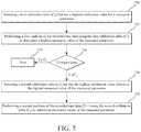
- FIG. 7is a flowchart of a method for calibrating a memory gauge with different calibration ranges
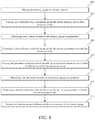
- FIG. 8is a flowchart of a method for processing recorded raw data with an adaptive calibration.
- FIG. 9is a schematic illustration of a computing device for implementing one or more of the methods discussed herein.
- the inventionis not limited to measuring a pressure with a memory gauge in a well, but it may be applied to other situations, as for example, using any measuring device or tool in a medium in which the measuring range for a given parameter is large and a maximum value of the given parameter to be measured with the measuring device varies based on the medium, e.g., ESP (Electric Submersible Pump) gauges or PCP (Progressive Cavity Pump) gauges or any permanent gauges.
- ESPElectrical Submersible Pump
- PCPProgressive Cavity Pump
- the accuracy of a memory gaugeis a percentage of the full scale of the gauge.
- the quartz gaugesare rated with an accuracy of 0.02% of their full scale.
- the accuracy of piezo memory gaugesusually is claimed as about 0.03 or 0.05% of their full scale. This means that the accuracy of a quartz memory gauge calibrated up to 1000 bars is 200 mbars whereas the accuracy of a piezo memory gauge calibrated up to 700 bars is 140 mbars.
- a memory gaugeis understood in the following to be a device that can measure at least one parameter, e.g., temperature or pressure or both. The measurements are stored in a memory associated with the memory gauge.
- the memoryis located inside the gauge device, as illustrated in FIG. 1 .
- the memoryis not physically located on the gauge.
- the memorymay be located at earth surface, and connected via a communication link (wired or wireless) to the gauge tool located on in the well.
- FIG. 2shows gauge 100 being connected through link 235 to a computing device 242 , which includes memory 240 .
- memory 240is not located on the gauge, but is linked through link 235 to the gauge.
- link 235may be wireless.
- reference to a “memory gauge”implies that a memory is associated with the link, the memory is (1) located on or inside the gauge or (2) only connected to the gauge, but not physically located on or inside the gauge.
- plural calibrationsare performed for the given memory gauge.
- a pressure memory gaugeinstead of performing a single calibration with a maximum value of 1000 bars, two or more calibrations may be performed, each calibration having a maximum value p i with p i being different from p j for any two calibrations “i” and “j”.
- “i”is an index describing the calibration number and this index may have a value between 2 and 100.
- p 1is 1000 bars
- p 2is 500 bars.
- a pressure sensor 308in this case (any known pressure sensor may be used for the memory gauge 300 ), implies measuring in a controlled environment (e.g., in a calibrating chamber or oven 330 in the lab) a pressure with the pressure sensor 308 while the temperature inside the chamber 330 is varied incrementally (in a controlled way), based on a known schedule of temperature.
- a pressure actuator 334may be located directly on the pressure sensor 308 (e.g., at the nose of the memory gauge) for generating a pressure directly on the pressure sensor.
- chamber 330may be an oil bath in which the pressure sensor 308 is placed and the ambient temperature of the pressure sensor is controlled by controlling the temperature of the oil bath. Other calibration methods may be used as known in the art.
- the associated calibration tables C 1 and C 2are generated and stored in the memory 310 of the memory gauge 300 .
- a processor 312may be connected to sensor 308 and memory 310 for receiving the data from the sensor and writing the corresponding values in the memory 310 . Processor 312 may also format this data to appear as calibration tables C 1 and C 2 .
- a processor 340 associated with the controlled environment 330may be electrically connected to memory gauge 300 for processing the data recorded by sensor 308 , for generating the calibration tables C 1 and C 2 , and/or for writing these tables into memory 310 .
- the step of writing the plural calibration tables (at least two) into the memory located in the memory gaugeis preferred because any two memory gauges, even if manufactured to have the same characteristics, would have different properties, and thus, different calibration matrices.
- an external devicee.g., laptop
- an external devicee.g., laptop
- FIG. 4shows a first calibration 446 of the memory gauge 300 for a maximum temperature of 150° C. and a maximum pressure of 700 bars.
- the pressure profile 440 and the temperature profile 442 for the first calibration 446are shown superimposed on the corresponding pressure profile 450 and temperature profile 452 of a second calibration 448 .
- the abscissaindicates the time over which the calibration has taken place, with the time interval t 0 to t 1 indicating a constant temperature of about 30° C., t 1 to t 2 a higher temperature, and so on.
- the ordinateindicates on the left the pressure and on the right the temperature.
- the pressure applied by the pressure actuator to the nose of the gaugee.g., with a dead well tester (DWT) (preferably being 5 ⁇ 10 ⁇ 4 accurate, pressure generator), is increased and recorded with the pressure sensor 308 .
- DWTdead well tester
- the data recorded in the memory 310 of the memory gauge 300includes the information shown in FIG. 4 , which is stored as a first calibrating table C 1 for the first range of pressures and temperatures and as a second calibrating table C 2 for the second range of pressures and temperatures.
- a first calibrating table C 1for the first range of pressures and temperatures
- a second calibrating table C 2for the second range of pressures and temperatures.
- many calibrating tablesmay be stored in the memory of a single memory gauge. If the memory gauge includes plural sensors, e.g., one for pressure, one for temperature and one for the flow of a fluid inside the well, plural calibration tables for each parameter may be generated and stored in the memory for each sensor.
- FIG. 3has illustrated one configuration of a memory gauge that can store plural calibration tables per sensor.
- FIG. 5illustrates a different configuration of a memory gauge specifically built to store the calibration tables.
- Memory gauge 500includes a body 502 , which is made of metal to resist the high temperatures and pressures inside the well.
- a sensor 508e.g., pressure or temperature or any other type of sensor
- Sensor 508is connected to a processing device 506 that is housed by body 502 .
- Processing device 506may include an analog to digital (A/D) converter 514 , which transforms the analog measurement of the sensor into digital data. If the sensor is digital, the A/D converter may be omitted or programmed to not affect the digital signal.
- A/Danalog to digital
- a calibration module 516which may be implemented in software in processor 512 or as a dedicated circuitry as shown in FIG. 5 , may store the calibration matrices C i , and provide them upon request, to processor 512 .
- Calibration module 516acts like a switch that selects one of the existing calibration matrices, e.g., C 1 or C 2 when only two matrices are present.
- the memory gauge 500is not able to exchange data with a surface device while collecting data in the well because there is no telemetry between the memory gauge and the surface when the memory gauge is located in the well.
- a linkmay be extending between the memory gauge 100 and the surface, and this link may transmit the recorded data from the gauge to the surface memory if no memory is provided on or inside the gauge. This link may also be used for deploying/retrieving the memory gauge inside the well. All recorded data 511 in the embodiment illustrated in FIG. 5 is stored in memory 510 .
- the memory gaugeWhen the acquisition is completed, the memory gauge is brought to the surface and made to communicate, via communication interface 520 , with an external device 530 , e.g., a computer, tablet, smartphone, etc.
- Memory gauge 500may be left in the well, hanging from a deploying device, e.g., wire as illustrated in FIG. 2 , during data collection so that the data is continuously or intermittently transmitted from the gauge to the surface as the survey progresses.
- the deploying toolis removed and the memory gauge uses a wing to be fixedly attached to the well. After all the data has been collected, the deploying tool is deployed again in the well for retrieving the memory gauge.
- Communication interface 520may be a wireless interface that uses existing communication methods, as, for example, Bluetooth, wi-fi, radio communication, etc., or may be a wired interface that connects through a cable (e.g., coaxial, Ethernet, etc.) directly to the surface computer 530 for communicating the recorded data.
- a wireless interfacethat uses existing communication methods, as, for example, Bluetooth, wi-fi, radio communication, etc.
- a wired interfacethat connects through a cable (e.g., coaxial, Ethernet, etc.) directly to the surface computer 530 for communicating the recorded data.
- the external device 530selects the maximum range calibration matrix (if pressure is measured, then the external device selects a first calibration matrix for the highest-pressure value) and runs a first analysis of the recorded data 511 with this calibration table. The first analysis produces the recorded pressures and the highest measured pressure P high is identified. Based on this highest measured pressure P high , the external device 530 may select a second calibration table that has its highest calibration pressure P calibration closest to the measured highest pressure P high .
- the first calibration tableis identical to the second calibration table, in which case, the optimal accuracy was obtained, and the recorded pressures are considered as being the measured pressure data.
- the two calibration tablesare different and the accuracy in the recorded pressures can be improved by using the second calibration table, which has the highest calibration pressure closer to the higher measured pressure than the first calibration table.
- the first calibration table C 1has a maximum pressure of 1000 bars and the second calibration table C 2 has a maximum pressure of 2000 bars.
- the memory gaugeis used in a well job in which the measured pressure does not exceed 500 bars.
- the first analysis of the recorded datauses the calibration table C 2 having the highest calibration pressure P calibration , i.e., 2000 bars.
- the external deviceselects the other calibration table C 1 (highest pressure 1000 bars) for the second analysis of the recorded data 511 .
- the data 511 recorded during that particular well jobis then accurate within 200 mbars instead of 400 mbars as a traditional memory gauge would have delivered.
- FIG. 6shows a step 600 of calibrating a given memory gauge 500 for at least two different calibration ranges.
- the first calibration rangegenerates a first calibration table C 1 and the second calibration range generates a second calibration table C 2 .
- the calibration rangesmay be for pressure, temperature, flow, or other parameters measured within a well with a memory gauge.
- the calibration of the memory gaugeis performed inside a controlled environment as discussed above with respect to FIG. 3 .
- the calibration tablesmay include the information illustrated, for example, in FIG. 4 .
- the generated calibration tablesare stored within the memory gauge, for example, in a dedicated memory 510 .
- the stepmay be applied to existing memory gauges which have a memory or to new memory gauges that have a calibration module 516 , as illustrated in FIG. 5 .
- the memory gaugeis deployed within a well for acquiring data.
- the preferred memory gaugetypically does not have electrical communication with the surface (i.e., no telemetry).
- the memory gaugerecords the raw data 511 (pressure or temperature or flow or a combination thereof) and stores this data in the memory 510 .
- the datamay be stored as analog data or digital data.
- the raw data recorded by the sensormay be stored as is or it may be slightly processed at the processor 512 , prior to being stored in memory 510 . This slight processing may include, for example, transforming the analog data into digital data.
- step 608after the recording has been finished, the memory gauge is retrieved from the well and connected to the external device 530 at the surface as illustrated in FIG. 5 .
- step 610the recorded data 511 is retrieved from the memory 508 of the memory gauge and stored into the external device.
- step 612the calibration tables C 1 from the memory gauge are transferred to the external device.
- step 614the calibration table having the largest calibration parameter (e.g., pressure P calibration if the sensor is a pressure sensor) is selected.
- a first analysis of the recorded data 511is performed using the calibration table selected in step 614 . A result of this analysis outputs the highest value of the measured parameter (e.g., P high ) with an uncertain accuracy.
- step 618the highest value of the measured parameter, calculated based on the calibration table selected in step 614 , is compared with the highest calibration pressure of the same calibration table. Based on this comparison, if the highest calibration pressure of another calibration table is closer to the highest value of the measured parameter than the highest calibration pressure of the calibration table selected in step 614 , then the method advances to step 620 , in which the method selects another calibration table having its highest calibration value as close as possible to the highest measured value determined in step 616 . Otherwise, the method outputs the results of the first analysis in step 624 and stops.
- the third calibration table having the highest calibration value 1500is selected as 1500 is closer to measured value 1300 than highest calibration value 1000 of the second calibration table.
- the external deviceHaving selected the most appropriate calibration table, the external device performs a second analysis in step 622 (considering that the first calibration table selected in step 614 was not the best), in which the highest measured value and the other measured values are determined with the best accuracy based on the selected calibration table. Step 622 might be omitted if the originally chosen calibration table is identical to the most appropriate calibration table, as discussed above.
- the external deviceoutputs all the measured values in a visual form, for example, as a printout or as a file or as an image on a screen.
- the calculations performed in the external devicemay be partially or totally performed in the processor of the memory gauge.
- the first analysis stepmay be performed in the memory gauge and the second analysis step may be performed in the external device.
- the memory gauge's processoris powerful enough, both the first and second analysis steps are performed in the memory gauge. If this is the case, the processing may start while the memory gauge is in the well.
- the span of the measured data(e.g., its range) may be determined and divided into various intervals and a best calibration table is selected for each interval. Then, the second analysis step uses the best calibration table for each interval and at the end, the measured data processed as a result of the second analysis step is put together to form a single set of data. Continuity problems that may appear at the borders of the selected intervals may be addressed by applying various tappers or known mathematical methods.
- the methodincludes a step 700 of selecting a first calibration table (C 1 ) that has a highest calibration value for a measured parameter, a step 702 of performing a first analysis of the recorded raw data using the first calibration table (C 1 ) to determine a highest measured value of the measured parameter, and a step 704 of comparing the highest measured value of the measured parameter with the calibration values of the first and second calibration tables.
- step 706the method advances to step 706 of selecting a second calibration table (C 2 ) that has the highest calibration value closest to the highest measured value of the measured parameter, and a step 708 of performing a second analysis of the recorded raw data using the second calibration table (C 2 ) to determine measured values of the measured parameter. If the highest measured value of the measured parameter is closer to the calibration values of the first calibration table, then the method proceeds from step 704 to step 710 , in which it outputs the measured data processed with the first calibration table.
- the methodincludes a step 800 of placing the memory gauge in a chamber, usually an oven or an oil bath, a step 802 of varying, in a controlled way, a first parameter (e.g., temperature) inside the chamber, up to a first maximum value, a step 804 of measuring with a sensor of the memory gauge a second parameter (e.g., pressure) while the first parameter is varied, a step 806 of generating a first calibration table for the sensor for the first and second parameters, with the first parameter varying up to the first maximum value, a step 808 of varying the first parameter inside the chamber, up to a second maximum value, which is different from the first maximum value, a step 810 of measuring with the sensor located on the memory gauge the second parameter, a step 812 of generating a second calibration table for the sensor for the first and second parameters, with the first parameter varying up to the second maximum value, and a step 814 of
- the computing device 900includes a processor 902 that is connected through a bus 904 to a storage device 906 .
- Computing device 900may also include an input/output interface 908 through which data can be exchanged with the processor and/or storage device.
- a keyboard, mouse or other devicemay be connected to the input/output interface 908 to send commands to the processor and/or to collect data stored in storage device or to provide data necessary to the processor. Results of this or another algorithm may be visualized on a screen 910 .
- the disclosed exemplary embodimentsprovide an apparatus and method for better processing raw data recorded inside a well. It should be understood that this description is not intended to limit the invention. On the contrary, the exemplary embodiments are intended to cover alternatives, modifications and equivalents, which are included in the spirit and scope of the invention as defined by the appended claims. Further, in the detailed description of the exemplary embodiments, numerous specific details are set forth in order to provide a comprehensive understanding of the claimed invention. However, one skilled in the art would understand that various embodiments may be practiced without such specific details.
Landscapes
- Physics & Mathematics (AREA)
- General Physics & Mathematics (AREA)
- Engineering & Computer Science (AREA)
- Life Sciences & Earth Sciences (AREA)
- General Life Sciences & Earth Sciences (AREA)
- Geophysics (AREA)
- Manufacturing & Machinery (AREA)
- Mining & Mineral Resources (AREA)
- Geology (AREA)
- Measuring Fluid Pressure (AREA)
- Fluid Mechanics (AREA)
- Geochemistry & Mineralogy (AREA)
- Environmental & Geological Engineering (AREA)
- Indication And Recording Devices For Special Purposes And Tariff Metering Devices (AREA)
- Radar Systems Or Details Thereof (AREA)
- Remote Sensing (AREA)
- Amplifiers (AREA)
- Circuits Of Receivers In General (AREA)
Abstract
Description
Claims (14)
Priority Applications (4)
| Application Number | Priority Date | Filing Date | Title |
|---|---|---|---|
| US15/481,713US11169032B2 (en) | 2017-04-07 | 2017-04-07 | Gauge with adaptive calibration and method |
| EP18162458.6AEP3422054B1 (en) | 2017-04-07 | 2018-03-19 | Gauge with adaptive calibration and method |
| CA2999141ACA2999141A1 (en) | 2017-04-07 | 2018-03-22 | Gauge with adaptive calibration and method |
| MX2018004032AMX2018004032A (en) | 2017-04-07 | 2018-04-02 | Gauge with adaptive calibration and method. |
Applications Claiming Priority (1)
| Application Number | Priority Date | Filing Date | Title |
|---|---|---|---|
| US15/481,713US11169032B2 (en) | 2017-04-07 | 2017-04-07 | Gauge with adaptive calibration and method |
Publications (2)
| Publication Number | Publication Date |
|---|---|
| US20180291732A1 US20180291732A1 (en) | 2018-10-11 |
| US11169032B2true US11169032B2 (en) | 2021-11-09 |
Family
ID=61801828
Family Applications (1)
| Application Number | Title | Priority Date | Filing Date |
|---|---|---|---|
| US15/481,713Active2038-12-08US11169032B2 (en) | 2017-04-07 | 2017-04-07 | Gauge with adaptive calibration and method |
Country Status (4)
| Country | Link |
|---|---|
| US (1) | US11169032B2 (en) |
| EP (1) | EP3422054B1 (en) |
| CA (1) | CA2999141A1 (en) |
| MX (1) | MX2018004032A (en) |
Families Citing this family (2)
| Publication number | Priority date | Publication date | Assignee | Title |
|---|---|---|---|---|
| CN115833967B (en)* | 2022-11-21 | 2025-05-23 | 创远信科(上海)技术股份有限公司 | Method, device, processor and storage medium for realizing automatic calibration processing for 5GNR frequency sweeper device CINR |
| WO2025018435A1 (en)* | 2023-07-14 | 2025-01-23 | 엘지전자 주식회사 | Method and device for beamforming in wireless communication system |
Citations (52)
| Publication number | Priority date | Publication date | Assignee | Title |
|---|---|---|---|---|
| US2053967A (en)* | 1936-01-15 | 1936-09-08 | Shell Dev | Apparatus for determining well temperatures |
| US3181063A (en)* | 1959-09-21 | 1965-04-27 | Hellige & Co Gmbh F | Dual sensitivity range calibration apparatus employing automatic sequential sensitivity alternation |
| US3440533A (en)* | 1966-04-01 | 1969-04-22 | Central Electr Generat Board | Portable potentiometric recorder testing and calibrating device |
| US3720813A (en)* | 1971-08-23 | 1973-03-13 | Damon Corp | Interpolative readout apparatus |
| US3740533A (en)* | 1970-01-23 | 1973-06-19 | Ballast Nedam Groep Nv | Method of controlling a process and apparatus for the performance of the method |
| US4663628A (en)* | 1985-05-06 | 1987-05-05 | Halliburton Company | Method of sampling environmental conditions with a self-contained downhole gauge system |
| US4665398A (en)* | 1985-05-06 | 1987-05-12 | Halliburton Company | Method of sampling and recording information pertaining to a physical condition detected in a well bore |
| US4689744A (en)* | 1985-01-14 | 1987-08-25 | Halliburton Company | Control method for a recording device |
| US4709234A (en)* | 1985-05-06 | 1987-11-24 | Halliburton Company | Power-conserving self-contained downhole gauge system |
| US4718011A (en)* | 1982-11-01 | 1988-01-05 | Western Atlas International, Inc. | Well logging data acquisition, telemetry and control method and system |
| US4866607A (en)* | 1985-05-06 | 1989-09-12 | Halliburton Company | Self-contained downhole gauge system |
| US5180973A (en)* | 1990-08-20 | 1993-01-19 | U.S. Philips Corporation | Self-calibrating crt measuring instrument |
| US5343963A (en)* | 1990-07-09 | 1994-09-06 | Bouldin Brett W | Method and apparatus for providing controlled force transference to a wellbore tool |
| US5710370A (en)* | 1996-05-17 | 1998-01-20 | Dieterich Technology Holding Corp. | Method for calibrating a differential pressure fluid flow measuring system |
| US6234008B1 (en) | 1999-12-08 | 2001-05-22 | Massachusetts Institute Of Technology | Method and apparatus for the direct measurement of moisture characteristics of porous samples of soil, wood, concrete and the like |
| US6272434B1 (en)* | 1994-12-12 | 2001-08-07 | Baker Hughes Incorporated | Drilling system with downhole apparatus for determining parameters of interest and for adjusting drilling direction in response thereto |
| US20020078732A1 (en)* | 2000-12-21 | 2002-06-27 | Bentley Ian N. | Method and apparatus for the calibration and compensation of sensors |
| US20020171560A1 (en)* | 1997-06-02 | 2002-11-21 | Schlumberger Technology Corporation | Reservoir management system and method |
| US20020195247A1 (en)* | 1997-06-02 | 2002-12-26 | Schlumberger Technology Corporation | Well-bore sensor apparatus and method |
| US20040122301A1 (en)* | 2002-09-25 | 2004-06-24 | Kiani Massl E. | Parameter compensated pulse oximeter |
| US20040249592A1 (en)* | 2003-06-06 | 2004-12-09 | Invensys Systems, Inc. | Multiple calibration ranges stored in a process transmitter |
| US20040253734A1 (en)* | 2001-11-13 | 2004-12-16 | Cully Firmin | Down-hole pressure monitoring system |
| US20050117034A1 (en)* | 2002-06-21 | 2005-06-02 | Microsoft Corp. | Temperature compensation in multi-camera photographic devices |
| US6932154B2 (en)* | 2003-09-16 | 2005-08-23 | Canada Tech Corporation | Pressure sensor insert for a downhole tool |
| US20050257611A1 (en) | 2004-05-21 | 2005-11-24 | Halliburton Energy Services, Inc. | Methods and apparatus for measuring formation properties |
| US20070032957A1 (en)* | 2005-07-28 | 2007-02-08 | Schlumberger Technology Corporation | High Temperature Wellbore Monitoring Method and Apparatus |
| US20090141771A1 (en)* | 2006-06-03 | 2009-06-04 | Owen William H | Temperature-sensing and transmitting assemblies, programmable temperature sensor units, and methods of making and using them |
| US20110128003A1 (en)* | 2009-11-30 | 2011-06-02 | Chevron U.S.A, Inc. | System and method for measurement incorporating a crystal oscillator |
| US20110267065A1 (en)* | 2009-11-30 | 2011-11-03 | Chevron U.S.A., Inc. | Packer fluid and system and method for remote sensing |
| US20120037422A1 (en)* | 2008-06-27 | 2012-02-16 | Wajid Rasheed | Drilling tool, apparatus and method for underreaming and simultaneously monitoring and controlling wellbore diameter |
| US20120265468A1 (en)* | 2011-04-15 | 2012-10-18 | Mark Kenneth Dennis | Variable tool calibration |
| US20130037260A1 (en)* | 2011-08-10 | 2013-02-14 | Stewart D. Reed | Systems and Methods for Downhole Communications Using Power Cycling |
| US20140019052A1 (en)* | 2012-07-13 | 2014-01-16 | Baker Hughes Incorporated | Device and method for predictive calibration |
| US20140077964A1 (en)* | 2012-09-19 | 2014-03-20 | Honeywell International Inc. | System and Method for Optimizing an Operation of a Sensor Used with Wellbore Equipment |
| US20140265619A1 (en)* | 2013-03-15 | 2014-09-18 | Merlin Technology, Inc. | Advanced Inground Device Power Control and Associated Methods |
| US20150148919A1 (en)* | 2013-11-27 | 2015-05-28 | Adept Ai Systems Inc. | Method and apparatus for artificially intelligent model-based control of dynamic processes using probabilistic agents |
| US20150218929A1 (en)* | 2014-02-04 | 2015-08-06 | Schlumberger Technology Corporation | Well-Logging System With Data Synchronization And Methods |
| US20150268117A1 (en)* | 2014-03-24 | 2015-09-24 | General Electric Company | Systems and methods for distributed pressure sensing |
| US20150345283A1 (en)* | 2012-12-07 | 2015-12-03 | Evolution Engineering Inc. | Back up directional and inclination sensors and method of operating same |
| US20160076918A1 (en)* | 2014-09-15 | 2016-03-17 | Avago Technologies General Ip (Singapore) Pte. Ltd. | Optical linear measurement system and method |
| US20160108720A1 (en)* | 2012-02-10 | 2016-04-21 | Austin Powder Company | Method and apparatus to measure borehole pressure during blasting |
| US20160123137A1 (en)* | 2013-06-04 | 2016-05-05 | Evolution Engineering Inc. | Method and Apparatus for Detecting Gamma Radiation Downhole |
| US20160168978A1 (en)* | 2014-12-15 | 2016-06-16 | Arthur H. Kozak | Methods and apparatuses for determining true vertical depth (tvd) within a well |
| US20160245049A1 (en)* | 2013-11-08 | 2016-08-25 | Maersk Olie Og Gas A/S | Apparatus and method for simulating and/or controlling fluid injection |
| US20160327684A1 (en)* | 2014-12-12 | 2016-11-10 | Halliburton Energy Services, Inc. | Optical computing device diagnostics and treatment |
| US20170101863A1 (en)* | 2014-07-03 | 2017-04-13 | Schlumberger Technology Corporation | System And Method For Downhole And Surface Measurements For An Electric Submersible Pump |
| US20170226813A1 (en)* | 2016-02-05 | 2017-08-10 | Weatherford Technology Holdings, Llc | Control of Hydraulic Power Flowrate for Managed Pressure Drilling |
| US20170268323A1 (en)* | 2015-10-22 | 2017-09-21 | Halliburton Energy Services, Inc. | Improving fault detectability through controller reconfiguration |
| US20170285221A1 (en)* | 2016-01-22 | 2017-10-05 | Saudi Arabian Oil Company | Generating dynamically calibrated geo-models in green fields |
| US20170328151A1 (en)* | 2016-05-10 | 2017-11-16 | Weatherford Technology Holdings, Llc | Drilling System and Method Having Flow Measurement Choke |
| US20180066513A1 (en)* | 2016-08-15 | 2018-03-08 | Sanvean Technologies Llc | Drilling Dynamics Data Recorder |
| US20180080310A1 (en)* | 2015-09-28 | 2018-03-22 | Hrl Laboratories, Llc | Opportunistic sensor fusion algorithm for autonomous guidance while drilling |
- 2017
- 2017-04-07USUS15/481,713patent/US11169032B2/enactiveActive
- 2018
- 2018-03-19EPEP18162458.6Apatent/EP3422054B1/enactiveActive
- 2018-03-22CACA2999141Apatent/CA2999141A1/enactivePending
- 2018-04-02MXMX2018004032Apatent/MX2018004032A/enunknown
Patent Citations (54)
| Publication number | Priority date | Publication date | Assignee | Title |
|---|---|---|---|---|
| US2053967A (en)* | 1936-01-15 | 1936-09-08 | Shell Dev | Apparatus for determining well temperatures |
| US3181063A (en)* | 1959-09-21 | 1965-04-27 | Hellige & Co Gmbh F | Dual sensitivity range calibration apparatus employing automatic sequential sensitivity alternation |
| US3440533A (en)* | 1966-04-01 | 1969-04-22 | Central Electr Generat Board | Portable potentiometric recorder testing and calibrating device |
| US3740533A (en)* | 1970-01-23 | 1973-06-19 | Ballast Nedam Groep Nv | Method of controlling a process and apparatus for the performance of the method |
| US3720813A (en)* | 1971-08-23 | 1973-03-13 | Damon Corp | Interpolative readout apparatus |
| US4718011A (en)* | 1982-11-01 | 1988-01-05 | Western Atlas International, Inc. | Well logging data acquisition, telemetry and control method and system |
| US4689744A (en)* | 1985-01-14 | 1987-08-25 | Halliburton Company | Control method for a recording device |
| US4663628A (en)* | 1985-05-06 | 1987-05-05 | Halliburton Company | Method of sampling environmental conditions with a self-contained downhole gauge system |
| US4665398A (en)* | 1985-05-06 | 1987-05-12 | Halliburton Company | Method of sampling and recording information pertaining to a physical condition detected in a well bore |
| US4709234A (en)* | 1985-05-06 | 1987-11-24 | Halliburton Company | Power-conserving self-contained downhole gauge system |
| US4866607A (en)* | 1985-05-06 | 1989-09-12 | Halliburton Company | Self-contained downhole gauge system |
| US5343963A (en)* | 1990-07-09 | 1994-09-06 | Bouldin Brett W | Method and apparatus for providing controlled force transference to a wellbore tool |
| US5180973A (en)* | 1990-08-20 | 1993-01-19 | U.S. Philips Corporation | Self-calibrating crt measuring instrument |
| US6272434B1 (en)* | 1994-12-12 | 2001-08-07 | Baker Hughes Incorporated | Drilling system with downhole apparatus for determining parameters of interest and for adjusting drilling direction in response thereto |
| US5710370A (en)* | 1996-05-17 | 1998-01-20 | Dieterich Technology Holding Corp. | Method for calibrating a differential pressure fluid flow measuring system |
| US20020195247A1 (en)* | 1997-06-02 | 2002-12-26 | Schlumberger Technology Corporation | Well-bore sensor apparatus and method |
| US20020171560A1 (en)* | 1997-06-02 | 2002-11-21 | Schlumberger Technology Corporation | Reservoir management system and method |
| US6234008B1 (en) | 1999-12-08 | 2001-05-22 | Massachusetts Institute Of Technology | Method and apparatus for the direct measurement of moisture characteristics of porous samples of soil, wood, concrete and the like |
| US20020078732A1 (en)* | 2000-12-21 | 2002-06-27 | Bentley Ian N. | Method and apparatus for the calibration and compensation of sensors |
| US20040253734A1 (en)* | 2001-11-13 | 2004-12-16 | Cully Firmin | Down-hole pressure monitoring system |
| US20050117034A1 (en)* | 2002-06-21 | 2005-06-02 | Microsoft Corp. | Temperature compensation in multi-camera photographic devices |
| US20040122301A1 (en)* | 2002-09-25 | 2004-06-24 | Kiani Massl E. | Parameter compensated pulse oximeter |
| US20040249592A1 (en)* | 2003-06-06 | 2004-12-09 | Invensys Systems, Inc. | Multiple calibration ranges stored in a process transmitter |
| US6932154B2 (en)* | 2003-09-16 | 2005-08-23 | Canada Tech Corporation | Pressure sensor insert for a downhole tool |
| US20050257611A1 (en) | 2004-05-21 | 2005-11-24 | Halliburton Energy Services, Inc. | Methods and apparatus for measuring formation properties |
| US20070032957A1 (en)* | 2005-07-28 | 2007-02-08 | Schlumberger Technology Corporation | High Temperature Wellbore Monitoring Method and Apparatus |
| US20090141771A1 (en)* | 2006-06-03 | 2009-06-04 | Owen William H | Temperature-sensing and transmitting assemblies, programmable temperature sensor units, and methods of making and using them |
| US20120037422A1 (en)* | 2008-06-27 | 2012-02-16 | Wajid Rasheed | Drilling tool, apparatus and method for underreaming and simultaneously monitoring and controlling wellbore diameter |
| US20110128003A1 (en)* | 2009-11-30 | 2011-06-02 | Chevron U.S.A, Inc. | System and method for measurement incorporating a crystal oscillator |
| US20110267065A1 (en)* | 2009-11-30 | 2011-11-03 | Chevron U.S.A., Inc. | Packer fluid and system and method for remote sensing |
| US20120265468A1 (en)* | 2011-04-15 | 2012-10-18 | Mark Kenneth Dennis | Variable tool calibration |
| US20130037260A1 (en)* | 2011-08-10 | 2013-02-14 | Stewart D. Reed | Systems and Methods for Downhole Communications Using Power Cycling |
| US20160108720A1 (en)* | 2012-02-10 | 2016-04-21 | Austin Powder Company | Method and apparatus to measure borehole pressure during blasting |
| US20140019052A1 (en)* | 2012-07-13 | 2014-01-16 | Baker Hughes Incorporated | Device and method for predictive calibration |
| WO2014011966A1 (en) | 2012-07-13 | 2014-01-16 | Baker Hughes Incorporated | Device and method for predictive calibration |
| US20140077964A1 (en)* | 2012-09-19 | 2014-03-20 | Honeywell International Inc. | System and Method for Optimizing an Operation of a Sensor Used with Wellbore Equipment |
| US20150345283A1 (en)* | 2012-12-07 | 2015-12-03 | Evolution Engineering Inc. | Back up directional and inclination sensors and method of operating same |
| US20170241255A1 (en)* | 2012-12-07 | 2017-08-24 | Evolution Engineering Inc. | Back up directional and inclination sensors and method of operating same |
| US20140265619A1 (en)* | 2013-03-15 | 2014-09-18 | Merlin Technology, Inc. | Advanced Inground Device Power Control and Associated Methods |
| US20160123137A1 (en)* | 2013-06-04 | 2016-05-05 | Evolution Engineering Inc. | Method and Apparatus for Detecting Gamma Radiation Downhole |
| US20160245049A1 (en)* | 2013-11-08 | 2016-08-25 | Maersk Olie Og Gas A/S | Apparatus and method for simulating and/or controlling fluid injection |
| US20150148919A1 (en)* | 2013-11-27 | 2015-05-28 | Adept Ai Systems Inc. | Method and apparatus for artificially intelligent model-based control of dynamic processes using probabilistic agents |
| US20150218929A1 (en)* | 2014-02-04 | 2015-08-06 | Schlumberger Technology Corporation | Well-Logging System With Data Synchronization And Methods |
| US20150268117A1 (en)* | 2014-03-24 | 2015-09-24 | General Electric Company | Systems and methods for distributed pressure sensing |
| US20170101863A1 (en)* | 2014-07-03 | 2017-04-13 | Schlumberger Technology Corporation | System And Method For Downhole And Surface Measurements For An Electric Submersible Pump |
| US20160076918A1 (en)* | 2014-09-15 | 2016-03-17 | Avago Technologies General Ip (Singapore) Pte. Ltd. | Optical linear measurement system and method |
| US20160327684A1 (en)* | 2014-12-12 | 2016-11-10 | Halliburton Energy Services, Inc. | Optical computing device diagnostics and treatment |
| US20160168978A1 (en)* | 2014-12-15 | 2016-06-16 | Arthur H. Kozak | Methods and apparatuses for determining true vertical depth (tvd) within a well |
| US20180080310A1 (en)* | 2015-09-28 | 2018-03-22 | Hrl Laboratories, Llc | Opportunistic sensor fusion algorithm for autonomous guidance while drilling |
| US20170268323A1 (en)* | 2015-10-22 | 2017-09-21 | Halliburton Energy Services, Inc. | Improving fault detectability through controller reconfiguration |
| US20170285221A1 (en)* | 2016-01-22 | 2017-10-05 | Saudi Arabian Oil Company | Generating dynamically calibrated geo-models in green fields |
| US20170226813A1 (en)* | 2016-02-05 | 2017-08-10 | Weatherford Technology Holdings, Llc | Control of Hydraulic Power Flowrate for Managed Pressure Drilling |
| US20170328151A1 (en)* | 2016-05-10 | 2017-11-16 | Weatherford Technology Holdings, Llc | Drilling System and Method Having Flow Measurement Choke |
| US20180066513A1 (en)* | 2016-08-15 | 2018-03-08 | Sanvean Technologies Llc | Drilling Dynamics Data Recorder |
Non-Patent Citations (1)
| Title |
|---|
| Partial European Search Report in European Application No. EP 18 16 2458 dated Dec. 5, 2018. |
Also Published As
| Publication number | Publication date |
|---|---|
| EP3422054B1 (en) | 2023-09-13 |
| EP3422054A2 (en) | 2019-01-02 |
| CA2999141A1 (en) | 2018-10-07 |
| MX2018004032A (en) | 2018-11-09 |
| US20180291732A1 (en) | 2018-10-11 |
| EP3422054A3 (en) | 2019-01-23 |
Similar Documents
| Publication | Publication Date | Title |
|---|---|---|
| AU2014391098B2 (en) | Time-lapse electromagnetic monitoring | |
| US20140019052A1 (en) | Device and method for predictive calibration | |
| RU2600493C2 (en) | Device and method for determination of geological boundaries | |
| US10989831B2 (en) | Determining permeability in subsurface anisotropic formations | |
| CA2594217A1 (en) | Reservoir sample chain-of-custody | |
| CN105556345B (en) | System and method for estimating porosity distribution in a subterranean reservoir | |
| US20210055436A1 (en) | Sparse Deconvolution And Inversion For Formation Properties | |
| EP3422054B1 (en) | Gauge with adaptive calibration and method | |
| US10139371B2 (en) | Casing defect determination using eddy current techniques | |
| CA3005431A1 (en) | Real time tracking of bending forces and fatigue in a tubing guide | |
| US11713668B2 (en) | Integrated well logging systems and methods | |
| EP2902814A2 (en) | Well-logging system with data synchronization and methods | |
| SA519410603B1 (en) | Methods to Synchronize Signals Among Antennas With Different Clock Systems | |
| SA519410882B1 (en) | A new porosity independent methodology for permeability prediction based on micro-resistivity images and laterolog resistivities | |
| GB2522709A (en) | An offshore pipe monitoring system | |
| WO2019190532A1 (en) | A method for combined resistivity and permitivity determination with borehole imagers | |
| WO2018038712A1 (en) | Borehole shape estimation field of the invention | |
| US20180120470A1 (en) | Apparatus and method for obtaining petrophysical images using electrical imager and multi-frequency dispersion measurements | |
| RU2600806C2 (en) | Methods and systems for determining the gap between the downhole instrument and the geological formation | |
| NO20131039A1 (en) | Low-frequency viscosity, density and viscoelasticity foils for use in boreholes | |
| CN103998714A (en) | Downhole visualization method | |
| US8534115B2 (en) | Systems and methods of determining parameter values in a downhole environment | |
| US20140118334A1 (en) | 3d visualization of borehole data | |
| WO2015126416A1 (en) | Determining water salinity and water-filled porosity of a formation | |
| WO2017132287A1 (en) | Downhole tension sensing apparatus |
Legal Events
| Date | Code | Title | Description |
|---|---|---|---|
| AS | Assignment | Owner name:SERCEL, FRANCE Free format text:ASSIGNMENT OF ASSIGNORS INTEREST;ASSIGNOR:BRAVARD, NICOLAS;REEL/FRAME:042195/0077 Effective date:20170412 | |
| STPP | Information on status: patent application and granting procedure in general | Free format text:RESPONSE TO NON-FINAL OFFICE ACTION ENTERED AND FORWARDED TO EXAMINER | |
| STPP | Information on status: patent application and granting procedure in general | Free format text:FINAL REJECTION MAILED | |
| STCV | Information on status: appeal procedure | Free format text:NOTICE OF APPEAL FILED | |
| STCV | Information on status: appeal procedure | Free format text:APPEAL BRIEF (OR SUPPLEMENTAL BRIEF) ENTERED AND FORWARDED TO EXAMINER | |
| STCV | Information on status: appeal procedure | Free format text:EXAMINER'S ANSWER TO APPEAL BRIEF MAILED | |
| STCV | Information on status: appeal procedure | Free format text:ON APPEAL -- AWAITING DECISION BY THE BOARD OF APPEALS | |
| STCV | Information on status: appeal procedure | Free format text:BOARD OF APPEALS DECISION RENDERED | |
| STPP | Information on status: patent application and granting procedure in general | Free format text:EX PARTE QUAYLE ACTION MAILED | |
| STPP | Information on status: patent application and granting procedure in general | Free format text:RESPONSE TO EX PARTE QUAYLE ACTION ENTERED AND FORWARDED TO EXAMINER | |
| STPP | Information on status: patent application and granting procedure in general | Free format text:NOTICE OF ALLOWANCE MAILED -- APPLICATION RECEIVED IN OFFICE OF PUBLICATIONS | |
| STPP | Information on status: patent application and granting procedure in general | Free format text:PUBLICATIONS -- ISSUE FEE PAYMENT VERIFIED | |
| STCF | Information on status: patent grant | Free format text:PATENTED CASE | |
| MAFP | Maintenance fee payment | Free format text:PAYMENT OF MAINTENANCE FEE, 4TH YEAR, LARGE ENTITY (ORIGINAL EVENT CODE: M1551); ENTITY STATUS OF PATENT OWNER: LARGE ENTITY Year of fee payment:4 |