US11168779B2 - Pulley device for a tensioner roller or winding roller - Google Patents
Pulley device for a tensioner roller or winding rollerDownload PDFInfo
- Publication number
- US11168779B2 US11168779B2US16/288,273US201916288273AUS11168779B2US 11168779 B2US11168779 B2US 11168779B2US 201916288273 AUS201916288273 AUS 201916288273AUS 11168779 B2US11168779 B2US 11168779B2
- Authority
- US
- United States
- Prior art keywords
- bearing
- screw
- bore
- tongue
- flange
- Prior art date
- Legal status (The legal status is an assumption and is not a legal conclusion. Google has not performed a legal analysis and makes no representation as to the accuracy of the status listed.)
- Active, expires
Links
Images


Classifications
- F—MECHANICAL ENGINEERING; LIGHTING; HEATING; WEAPONS; BLASTING
- F16—ENGINEERING ELEMENTS AND UNITS; GENERAL MEASURES FOR PRODUCING AND MAINTAINING EFFECTIVE FUNCTIONING OF MACHINES OR INSTALLATIONS; THERMAL INSULATION IN GENERAL
- F16H—GEARING
- F16H57/00—General details of gearing
- F16H57/0018—Shaft assemblies for gearings
- F16H57/0031—Shaft assemblies for gearings with gearing elements rotatable supported on the shaft
- F—MECHANICAL ENGINEERING; LIGHTING; HEATING; WEAPONS; BLASTING
- F16—ENGINEERING ELEMENTS AND UNITS; GENERAL MEASURES FOR PRODUCING AND MAINTAINING EFFECTIVE FUNCTIONING OF MACHINES OR INSTALLATIONS; THERMAL INSULATION IN GENERAL
- F16C—SHAFTS; FLEXIBLE SHAFTS; ELEMENTS OR CRANKSHAFT MECHANISMS; ROTARY BODIES OTHER THAN GEARING ELEMENTS; BEARINGS
- F16C19/00—Bearings with rolling contact, for exclusively rotary movement
- F16C19/02—Bearings with rolling contact, for exclusively rotary movement with bearing balls essentially of the same size in one or more circular rows
- F16C19/14—Bearings with rolling contact, for exclusively rotary movement with bearing balls essentially of the same size in one or more circular rows for both radial and axial load
- F16C19/18—Bearings with rolling contact, for exclusively rotary movement with bearing balls essentially of the same size in one or more circular rows for both radial and axial load with two or more rows of balls
- F—MECHANICAL ENGINEERING; LIGHTING; HEATING; WEAPONS; BLASTING
- F16—ENGINEERING ELEMENTS AND UNITS; GENERAL MEASURES FOR PRODUCING AND MAINTAINING EFFECTIVE FUNCTIONING OF MACHINES OR INSTALLATIONS; THERMAL INSULATION IN GENERAL
- F16H—GEARING
- F16H55/00—Elements with teeth or friction surfaces for conveying motion; Worms, pulleys or sheaves for gearing mechanisms
- F16H55/32—Friction members
- F16H55/36—Pulleys
- F—MECHANICAL ENGINEERING; LIGHTING; HEATING; WEAPONS; BLASTING
- F16—ENGINEERING ELEMENTS AND UNITS; GENERAL MEASURES FOR PRODUCING AND MAINTAINING EFFECTIVE FUNCTIONING OF MACHINES OR INSTALLATIONS; THERMAL INSULATION IN GENERAL
- F16H—GEARING
- F16H7/00—Gearings for conveying rotary motion by endless flexible members
- F16H7/08—Means for varying tension of belts, ropes or chains
- F—MECHANICAL ENGINEERING; LIGHTING; HEATING; WEAPONS; BLASTING
- F16—ENGINEERING ELEMENTS AND UNITS; GENERAL MEASURES FOR PRODUCING AND MAINTAINING EFFECTIVE FUNCTIONING OF MACHINES OR INSTALLATIONS; THERMAL INSULATION IN GENERAL
- F16H—GEARING
- F16H7/00—Gearings for conveying rotary motion by endless flexible members
- F16H7/18—Means for guiding or supporting belts, ropes, or chains
- F16H7/20—Mountings for rollers or pulleys
- F—MECHANICAL ENGINEERING; LIGHTING; HEATING; WEAPONS; BLASTING
- F16—ENGINEERING ELEMENTS AND UNITS; GENERAL MEASURES FOR PRODUCING AND MAINTAINING EFFECTIVE FUNCTIONING OF MACHINES OR INSTALLATIONS; THERMAL INSULATION IN GENERAL
- F16H—GEARING
- F16H7/00—Gearings for conveying rotary motion by endless flexible members
- F16H7/08—Means for varying tension of belts, ropes or chains
- F16H2007/0863—Finally actuated members, e.g. constructional details thereof
- F16H2007/0865—Pulleys
Definitions
- the present inventionrelates to the field of pulley devices for tensioner rollers or winding rollers that are intended to cooperate with a belt, for example a timing belt or drive belt of a motor vehicle internal combustion engine.
- rollersserve generally to permanently maintain tension in the belt in a given range or to locally modify the path taken thereby.
- the rollersare thus referred to as tensioner rollers and winding rollers, respectively.
- the pulleyis rotatably mounted on a threaded screw body via a bearing, the roller then being fixed directly or indirectly to the engine block or to an element of a tensioner roller device, for example an articulated arm or an eccentric.
- the bearinggenerally comprises a fixed inner ring having a bore through which the screw passes, a rotating outer ring surmounted by the pulley, and at least one row of rolling elements interposed between the rings.
- Such devicesare often equipped with additional protective flanges that help to protect the device from contaminants or spatter originating from the outside environment.
- the flangealso serves as a thrust washer for the head of the screw.
- Pulley devicesare preferably delivered to motor vehicle equipment manufacturers or to motor vehicle manufacturers in a manner equipped with their screws and their flanges. Therefore, it is desirable for the device to form an assembly that is incapable of being dismantled, is easy to handle and to transport, without any risk of accidental dismantling, and needs to be able to be mounted without any other particular preparation by simply tightening the screw.
- the threaded screwhas to be inserted into the bore of the flange, deforming the interior projections of the flange.
- the thread of the screwcan be damaged as a result, making the screw unusable or reducing the force keeping it together with the support in which it is screwed. This may result in a need to change the screw, and thus an additional cost and an additional assembly operation, or a risk of the pulley device coming apart from its support during operation, and thus a drop-in performance of the device.
- the present inventionaims to remedy this drawback.
- the present inventionaims to provide a pulley device that is resistant to high levels of pollution, is particularly economical, is easy and safe to mount, forming a subassembly that is incapable of being dismantled, and has a smaller axial and radial space requirement.
- the inventionrelates to a pulley device for a tensioner roller or winding roller of a belt, comprising a pulley, a bearing, a protective flange and a screw.
- the bearingis provided with a rotating outer ring surmounted by the pulley, and with a fixed inner ring, the rings being coaxial and the bearing having a mounting bore.
- the protective flangecomprises a substantially radial portion bearing against a front surface of the bearing, and a bore.
- the screwcomprises a body housed in the bores of the bearing and the flange, and a screw head at one end of the body, the screw head bearing against the substantially radial portion of the flange.
- the substantially radial portion of the flangecomprises at least one tongue cut into the portion and extending towards the body of the screw.
- the tongueis provided with a plastically deformable part which extends in a substantially axial direction, and with an inner free end having a bore forming a portion of the bore of the flange.
- the tongueis configured such that it can pass from a first, undeformed configuration into a second, deformed configuration.
- the first, undeformed configurationcorresponds to a tongue of which the plastically deformable part is in an undeformed initial configuration, the bore of the tongue having an inside diameter strictly greater than the outside diameter of the body of the screw.
- the second, deformed configurationcorresponds to a tongue of which the plastically deformable part is in a deformed configuration against which the head of the screw comes to bear, the tongue then extending radially in its entirety, and the bore of the tongue passing into the immediate vicinity of or into contact with the body of the screw.
- the bearingis a plain bearing.
- the bearingis a bearing having rolling elements, at least one row of rolling elements being radially interposed between the outer and inner rings of the bearing.
- the rolling elementsare balls.
- a cagemaintains the circumferential spacing of the rolling elements.
- a washeris interposed between the screw head and the substantially radial portion of the flange.
- the inner ring of the bearingcomprises a bore forming the mounting bore of the bearing.
- the bearingcomprises an annular spacer interposed between the inner ring and the body of the screw, the spacer being provided with an outer surface fitted in a bore of the inner ring, with a front surface against which the substantially radial portion of the flange comes to bear, and with a bore forming a mounting bore for the bearing in which the body of the screw is housed.
- the substantially radial portion of the flangecomprises a first radial portion of small diameter that is provided with an inner edge forming the bore of the flange and with an outer edge, a second radial portion of large diameter that is provided with an inner edge and with an outer edge, and an intermediate portion connecting the outer edge of the first radial portion and the inner edge of the second radial portion.
- the intermediate portionis cylindrical.
- the intermediate portionis frustoconical.
- the outer edge of the second radial portion of large diameterextends in the immediate vicinity of the pulley to form a narrow passage.
- the flangecomprises an axial portion that extends axially from the bore of the substantially radial portion and is housed in the mounting bore of the bearing.
- the axial portionis mounted securely in the mounting bore of the bearing.
- the axial portionis mounted tightly in the mounting bore of the bearing.
- the axial portioncomprises retaining means that cooperate with the central mounting bore of the bearing.
- the at least one tongueis cut into the first radial portion of small diameter of the flange.
- the head of the screwis stepped.
- the body of the screwcomprises a smooth portion and a threaded portion.
- the smooth portionis arranged axially between the screw head and the threaded portion.
- the outside diameter of the smooth portionis strictly less than the outside diameter of the threaded portion.
- the tongueextends radially in the immediate vicinity of or in contact with the smooth portion of the body of the screw.
- the plastically deformable part of the tonguecomes to bear against the front surface of the inner ring of the bearing.
- the plastically deformable part of the tonguecomes to bear against the front surface of the spacer of the bearing.
- the plastically deformable partis a circumferential boss extending substantially axially away from the bearing.
- the plastically deformable partis the free inner end of the tongue having a frustoconical shape and extending substantially axially away from the bearing.
- the pulleyis made of metal, for example of steel.
- the pulleyis made of plastics material, for example of polyamide.
- the pulleyis formed by overmoulding plastics material on the outer ring of the bearing.
- the flangeis made of metal, for example of steel.
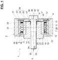
- FIG. 1is a view in axial section of a pulley device according to a first embodiment in a first, undeformed configuration
- FIG. 2is a perspective front view of a flange for the pulley device in FIG. 1 ;
- FIG. 3is a view in axial section of the pulley device according to the first embodiment in a second, deformed configuration
- FIG. 4is a view in axial section of a pulley device according to a second embodiment in a first, undeformed configuration
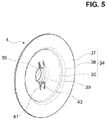
- FIG. 5is a perspective front view of a flange for the pulley device in FIG. 4 .
- a pulley device for a tensioner roller or winding roller of a beltbearing the overall reference 1 , has a geometric axis X 1 and comprises a pulley 2 designed to cooperate with a belt (not shown), a bearing 3 , a protective flange 4 , and a screw 5 .
- the bearing 3comprises a fixed inner ring 6 , a rotating outer ring 7 , two rows of rolling elements 8 and 9 , in the form of balls here, that are disposed between the rings, and cages 10 and 11 that maintain the circumferential spacing of the rolling elements 8 and 9 , respectively.
- the inner ring 6 and outer ring 7are concentric.
- the ringsare solid, obtained by machining or grinding with removal of material from metal tubes, bars, forged parts or rolled blanks.
- the inner ring 6comprises a bore 14 , an outer cylindrical surface 15 provided with raceways that have, in axial section, a concave internal profile suitable for the rolling elements 8 , 9 , and two front surfaces 16 , 17 .
- the outer ring 7comprises a cylindrical bore 18 provided with raceways that have, in axial section, a concave internal profile suitable for the rolling elements 8 , 9 , an outer cylindrical surface 19 on which the pulley 2 is mounted, and two front surfaces 20 , 21 .
- the bearingmay comprise a different number of rows of rolling elements arranged between the outer and inner rings, for example a single row of rolling elements.
- the bearingmay comprise other types of rolling elements, for example tapered rollers or needles.
- the bearingmay be a plain bearing.
- the bearing 3also comprises a spacer 22 .
- the spacer 22is annular and is provided with an outer surface 23 fitted in the bore 14 of the inner ring 6 , with a bore 24 forming the mounting bore of the bearing 3 , and with two front surfaces 25 , 26 .
- the spacer 22extends axially out of the bearing 3 in the axial direction towards a support on which the pulley device 1 is intended to be mounted.
- the spacer 22advantageously comprises a radial rim 27 against which the front face 16 of the inner ring 6 of the bearing 3 can come to bear.
- the radial rim 27comprises a surface for bearing against the support of the device 1 .
- the bearing 3does not comprise a spacer, the bore 14 of the inner ring 6 forming the mounting bore of the bearing 3 .
- the pulley 2may advantageously be made of plastics material, and preferably of polyamide, for example of PA6 or PA66.
- the pulley 2may advantageously be formed by overmoulding plastics material on the outer ring 7 of the bearing 3 . This results in excellent cohesion between these parts.
- the pulley 2may be made of metal material, for example of steel, and be mounted tightly on the outer cylindrical surface 19 of the outer ring 7 .
- the pulley 2may also have other shapes that are optimized depending on the needs of the application.
- the screw 5comprises a body 30 and a head 31 at one end of the body 30 .
- the body 30comprises a threaded portion 32 and a smooth portion 33 disposed between the threaded portion 32 and the head 31 .
- the body 30is housed in the mounting bore of the bearing 3 , in this case the bore 24 of the spacer 22 .
- the protective flange 4comprises a substantially radial portion 34 with a first radial portion 35 of small diameter that is provided with an inner edge forming the bore 36 of the flange 4 and with an outer edge, a second radial portion 37 of large diameter that is provided with an inner edge and with an outer edge, and a cylindrical intermediate portion 38 connecting the outer edge of the first radial portion 35 and the inner edge of the second radial portion 37 .
- the intermediate portion 38may be frustoconical.
- the outer edge of the second radial portion 37 of large diameterextends in the immediate vicinity of the pulley 2 to form a narrow passage that reduces the risk of outside contaminants intruding into the vicinity of the bearing 3 , and more particularly the bearing surfaces between the rolling elements 8 , 9 and the inner ring 6 and outer ring 7 .
- the seals 12 , 13are involved in the sealing and further reduce the risk of harmful intrusion, the flange 4 forming a first barrier in an environment with high levels of pollution.
- the first radial portion 35comes to bear against the front surface 17 of the inner ring 6 and the front surface 26 of the spacer 22 situated opposite the rim 27 , and thus of the support on which the device 1 is intended to be mounted.
- the head 31 of the screw 5has a relatively flat surface that comes to bear against the first radial portion 35 of the flange 4 , the first radial portion 35 being axially jammed between the head 31 of the screw 5 and the inner ring 6 of the bearing 3 .
- a washermay be interposed between the screw head and the substantially radial portion of the flange.
- the flange 4also comprises an axial portion 39 extending axially from the inner edge of the first radial portion 35 .
- the axial portion 39is housed and secured in the mounting bore 24 of the bearing 3 .
- the bore 24 of the spacer 22is provided with a circumferential groove 40 , the axial portion 39 being radially deformed to be partially housed in the circumferential groove 40 .
- the flange 4is kept axially and radially together with the bearing 3 via its axial portion 39 that cooperates with the walls of the circumferential groove 40 provided in the spacer 22 .
- the circumferential groovemay be provided in the bore of the inner ring of the bearing if the latter does not have a spacer.
- the axial portion of the flangemay be mounted tightly in the bore of the bearing.
- the axial portionis mounted securely in the mounting bore of the bearing by any other suitable means, for example by adhesive bonding.
- the substantially radial portion 34 of the flange 4comprises two tongues 41 cut into the portion 34 .
- the tongues 41are radially opposite one another and are identical.
- the flange 4may comprise a single tongue, or more than two.
- Each of the tongues 41extends towards the body 30 of the screw 5 .
- the tonguesare each provided with a plastically deformable part 42 that extends in a substantially axial direction, and with an inner free end 43 having a bore that forms a portion of the bore 36 of the flange 4 .
- the plastically deformable part 42 of each of the tongues 41is a circumferential boss that extends substantially axially away from the bearing 3 .
- the tongues 41are configured such that they can pass from a first, undeformed configuration, illustrated in FIG. 1 , to a second, deformed configuration, illustrated in FIG. 3 .
- the substantially radial portion 34 provided with the tongues 41comes to bear against the front surfaces of the inner ring 6 and of the spacer 22 of the bearing.
- the flange 4defines a bore 36 formed partially by the inner edge of the substantially radial portion and by the inner free ends 43 of the tongues 41 . Since the inside diameter of the bore 36 of the flange 4 is strictly greater than the outside diameter of the body 30 of the screw 5 , the body 30 can be inserted into the bore 36 without there being the slightest contact therebetween. The body 30 is then inserted into the mounting bore 24 of the bearing 3 until the head 31 of the screw 5 comes to bear against the bosses 42 of the tongues 41 .
- the screw 5can thus be inserted into the device 1 in this first configuration easily and without any risk of damaging the thread 32 .
- the flange 4centers the screw 5 , ensuring that the screw 5 , for the one part, and the pulley 2 and the bearing 3 , for the other part, are centered, this potentially making it easier to screw the screw 5 into a support provided with a tapped hole for this purpose.
- an axial forceis applied to the screw 5 in the insertion direction thereof.
- the forceis such that the head 31 exerts an axial force on the bosses 42 of the tongues 41 and thus deforms them until they are completely flattened against the front surface 26 of the spacer 22 .
- the forcecan be applied via a washer between the screw head and the flange, if appropriate.
- the tongues 41thus extend entirely radially.
- the axial extension of the boss 42 of each tongue 41is converted in the radial direction, the radial length of each tongue 41 thus being increased.
- the inner free ends 43 of the tongues 41thus pass into the immediate vicinity or into contact with the body 30 of the screw 5 .
- the screw 5is retained axially and radially by the tongues 41 of the flange in the second configuration.
- the pulley device 1forms an assembly that is incapable of being dismantled and is made up of the pulley 2 , the bearing 3 with the spacer 22 , the flange 4 and the screw 5 .
- Such a devicecan be easily handled, transported, and then installed on an assembly line without any risk of parts being lost, then installed on a support by screwing the screw into a tapped hole for this purpose without any other particular preparation.
- the flange 4can be manufactured economically by cutting out and stamping a blank made of sheet metal, for example steel.
- the smooth part 33 of the body 30 of the screw 5can have an outside diameter strictly less than the outside diameter of the threaded portion 32 to form an annular groove in which the free ends 43 of the tongues 41 are housed. This arrangement makes it possible to improve the axial retention of the screw.
- the head 31 of the screw 5is flush with the radial plane defining the overall exterior size of the pulley 2 .
- the screw 5 and the flange 4do not increase the overall size of the assembly, the overall size remaining that defined by the pulley 2 on the outer side of the device 1 .
- the plastically deformable part 42 of each of the tongues 41is the inner free end 43 of the tongue 41 having a frustoconical shape and extending substantially axially towards the head 31 of the screw 5 .
- the frustoconical inner free end 43 of each tongue 41has an inside diameter strictly greater than the outside diameter of the body 30 of the screw 5 , and more particularly of the threaded portion 32 , to allow contact-free insertion of the body 30 of the screw 5 into the flange 4 .
- the tongues 41can pass into a second, deformed configuration following the flattening of the frustoconical inner free ends 43 by application of an axial force via the head 31 of the screw 5 .
- the pulley device 1is then in a configuration similar to the one illustrated in FIG. 3 , the tongues extending in the immediate vicinity of or in contact with the body 30 of the screw 5 in order to ensure that the latter is axially and radially retained.
- the pulley devicecan be adapted in terms of cost, performance and ease of use.
Landscapes
- Engineering & Computer Science (AREA)
- General Engineering & Computer Science (AREA)
- Mechanical Engineering (AREA)
- Pulleys (AREA)
- Devices For Conveying Motion By Means Of Endless Flexible Members (AREA)
Abstract
Description
Claims (8)
Applications Claiming Priority (2)
| Application Number | Priority Date | Filing Date | Title |
|---|---|---|---|
| FR1851904 | 2018-03-06 | ||
| FR1851904AFR3078758B1 (en) | 2018-03-06 | 2018-03-06 | PULLEY DEVICE FOR TENSIONER OR ROLLER |
Publications (2)
| Publication Number | Publication Date |
|---|---|
| US20190277389A1 US20190277389A1 (en) | 2019-09-12 |
| US11168779B2true US11168779B2 (en) | 2021-11-09 |
Family
ID=62455681
Family Applications (1)
| Application Number | Title | Priority Date | Filing Date |
|---|---|---|---|
| US16/288,273Active2039-10-22US11168779B2 (en) | 2018-03-06 | 2019-02-28 | Pulley device for a tensioner roller or winding roller |
Country Status (4)
| Country | Link |
|---|---|
| US (1) | US11168779B2 (en) |
| CN (1) | CN110230674B (en) |
| DE (1) | DE102019202672A1 (en) |
| FR (1) | FR3078758B1 (en) |
Citations (118)
| Publication number | Priority date | Publication date | Assignee | Title |
|---|---|---|---|---|
| US1482579A (en)* | 1923-01-05 | 1924-02-05 | Budd G Nice | Ball-bearing wheel |
| US1627558A (en)* | 1924-03-27 | 1927-05-10 | Prec Metal Workers | Sheave |
| US1845631A (en)* | 1929-06-03 | 1932-02-16 | Grand Rapids Hardware Co | Sash pulley |
| US1848144A (en)* | 1928-07-05 | 1932-03-08 | Alexis R Pribil | Pressed steel ball bearing wheel |
| US1903776A (en)* | 1931-02-09 | 1933-04-18 | Formica Insulation Company | Method of securing a bearing within a pulley |
| US2137987A (en)* | 1936-02-11 | 1938-11-22 | Fafnir Bearing Co | Pulley |
| US2198831A (en)* | 1937-08-26 | 1940-04-30 | Westinghouse Electric & Mfg Co | Composite pulley |
| US2315357A (en)* | 1940-01-31 | 1943-03-30 | Midland Steel Prod Co | Ball-bearing annulus and method of making it |
| US2349281A (en)* | 1942-02-07 | 1944-05-23 | George H Kendall | Pulley bearing |
| US2530665A (en)* | 1943-07-21 | 1950-11-21 | Fafnir Bearing Co | Bearing |
| US2655813A (en)* | 1950-08-10 | 1953-10-20 | Edward N Howell | Sheave |
| US2669878A (en)* | 1950-10-10 | 1954-02-23 | Nelson Thomas Edward | Pulley construction |
| US3367199A (en)* | 1966-05-25 | 1968-02-06 | Dankowski Gerhard | Pulley and bearing assembly |
| US3490285A (en)* | 1967-08-15 | 1970-01-20 | Schaeffler Ohg Industriewerk | Convex pulley |
| US3767279A (en)* | 1971-12-09 | 1973-10-23 | Skf Ind Co | Flexible flange for bearings, preferably rolling bearings |
| US3789683A (en)* | 1971-11-18 | 1974-02-05 | Frost & Son C L | Rotatable member assembly and method for making same |
| US3825312A (en)* | 1973-02-09 | 1974-07-23 | Borg Warner | Shaft lock device |
| US3871241A (en)* | 1974-01-23 | 1975-03-18 | Illinois Tool Works | Take-up pulley |
| US3881789A (en)* | 1971-03-25 | 1975-05-06 | Kornylac Co | Conveyor roller and bearing seal |
| US3918277A (en)* | 1972-11-13 | 1975-11-11 | Skf Ind Trading & Dev | Bearing assembly |
| US3990136A (en)* | 1975-01-17 | 1976-11-09 | Wada Seiko Kabushiki Kaisha (Wada Seiko Co., Ltd.) | Method for producing revolving parts |
| US4010987A (en)* | 1975-10-23 | 1977-03-08 | C. L. Frost & Son, Inc. | Removable seal for bearings |
| US4033196A (en)* | 1975-11-26 | 1977-07-05 | Toyota Jidosha Kogyo Kabushiki Kaisha | Timing belt tensioner |
| US4073551A (en)* | 1976-07-08 | 1978-02-14 | Freeway Corporation | Rolling type bearing and method for making same |
| US4402678A (en)* | 1978-11-06 | 1983-09-06 | Dyneer Corporation | Clutch housing and pulley assembly |
| US4443210A (en)* | 1980-06-27 | 1984-04-17 | Skf Kugellagerfabriken Gmbh | Tension roller for belt drives |
| US4457740A (en)* | 1980-05-30 | 1984-07-03 | Skf Kugellagerfabriken Gmbh | Pin for tension rollers |
| US4474562A (en)* | 1980-12-03 | 1984-10-02 | Fag Kugelfischer Georg Schafer & Co. | Tensioner for motor-vehicle timing belt |
| US4504252A (en)* | 1980-03-07 | 1985-03-12 | Nissan Motor Company, Limited | Belt tensioner |
| US4516962A (en)* | 1982-12-16 | 1985-05-14 | Skf Kugellagerfabriken Gmbh | Tension roller for drive belts |
| US4518372A (en)* | 1983-10-24 | 1985-05-21 | Dye Donald D | Idler pulley and method of mounting a precision bearing |
| US4534749A (en)* | 1982-05-11 | 1985-08-13 | Skf Gmbh | Pulley |
| US4557708A (en)* | 1983-06-22 | 1985-12-10 | Skf Kugellagerfabriken Gmbh | Tension roller |
| US4568316A (en)* | 1984-04-26 | 1986-02-04 | Fmc Corporation | Multiple sheave mechanism with overlapping fit |
| US4571227A (en)* | 1984-02-01 | 1986-02-18 | Riv-Skf Officine Di Villar Perosa S.P.A. | Belt drive unit for transmitting drive between the drive shaft on an internal combustion engine and associated accessories |
| US4591352A (en)* | 1980-05-16 | 1986-05-27 | Skf Kugellagerfabriken Gmbh | Tension roller |
| US4610646A (en)* | 1980-09-27 | 1986-09-09 | Skf Kugellagerfabriken Gmbh | Roller, especially a tension roller for a belt drive |
| US4610645A (en)* | 1984-03-09 | 1986-09-09 | Riv-Skf Officine Di Villar Perosa S.P.A. | Belt stretcher unit designed for assembly on a flexible drive particularly on a motor vehicle |
| US4668209A (en)* | 1984-11-12 | 1987-05-26 | Nippon Seiko Kabushiki Kaisha | Plastic-surrounded bearing |
| US4831705A (en)* | 1987-06-17 | 1989-05-23 | Kabushiki Kaisha Kanemitsu | Method of manufacturing a sheet metal poly-V pulley |
| US4917655A (en)* | 1989-03-01 | 1990-04-17 | Ina Bearing Co., Inc. | Self adjusting timing belt tensioner |
| US5630769A (en)* | 1993-12-17 | 1997-05-20 | Ina Walzlager Schaeffler Kg | Tension roller for belt drives |
| US5725448A (en)* | 1994-12-28 | 1998-03-10 | Ntn Corporation | Idler pulley |
| US5728020A (en)* | 1995-09-06 | 1998-03-17 | Ntn Corporation | Pulley and ball bearing for pulleys |
| US5913743A (en)* | 1996-07-08 | 1999-06-22 | Koyo Seiko Co., Ltd. | Auto-tensioner |
| US6001037A (en)* | 1996-12-19 | 1999-12-14 | Dayco Europe S.P.A. | Tensioning device for belts, in particular toothed belts |
| US6010420A (en)* | 1995-08-21 | 2000-01-04 | Ntn Corporation | Pulley, ball bearing and fan for preventing the occurence of abnormal noise under cold ambient conditions |
| DE19836191A1 (en) | 1998-08-10 | 2000-02-17 | Schaeffler Waelzlager Ohg | Fixing unit for a belt idler roller comprises an elastic slit holder ring is inserted under preload into the bearing bore to secure the unit during its transport |
| US6102822A (en)* | 1997-09-30 | 2000-08-15 | Ntn Corporation | Pulley |
| US6196720B1 (en)* | 1998-03-19 | 2001-03-06 | Ntn Corporation | Bearing for automobile pulleys |
| US6220982B1 (en)* | 1997-10-31 | 2001-04-24 | Ntn Corporation | Idler pulley |
| US6241257B1 (en)* | 1997-11-22 | 2001-06-05 | Skf Gmbh | Fastening device for belt pulleys |
| US6270001B1 (en)* | 1999-03-26 | 2001-08-07 | Skf France | Method of manufacturing a pulley with integral bearing |
| US6293885B1 (en)* | 2000-03-14 | 2001-09-25 | The Gates Corporation | Idler pulley |
| US6450689B1 (en)* | 1999-12-08 | 2002-09-17 | Tokyo Sunworker Co., Ltd. | Roller and method of producing the same |
| US6572270B2 (en)* | 2000-07-21 | 2003-06-03 | Nsk Ltd. | Rolling bearing unit |
| US6605574B2 (en)* | 2001-01-26 | 2003-08-12 | Ntn Corporation | Grease sealed bearing for automobile |
| US6659649B2 (en)* | 2001-01-30 | 2003-12-09 | Nsk Ltd. | Rotation support apparatus for compressor pulley |
| US6692393B2 (en)* | 2000-12-21 | 2004-02-17 | Ntn Corporation | Pulley ball bearing and pulley |
| US20040097313A1 (en)* | 2000-09-06 | 2004-05-20 | Ina Walzlager Schaeffler Ohg | Deflection pulley for a traction mechanism drive |
| US20040178398A1 (en)* | 2003-03-13 | 2004-09-16 | Miller Bradley D. | Spun-formed rotatable object with bearing and method of manufacture |
| US6860639B2 (en)* | 2002-01-15 | 2005-03-01 | Denso Corporation | Rotator with bearing, and method for manufacturing the same |
| US7011593B2 (en)* | 2002-03-05 | 2006-03-14 | Ina-Schaeffler Kg | Tensioning or deflection pulley for a belt drive |
| US7041019B2 (en)* | 2002-03-15 | 2006-05-09 | Sanden Corporation | Automotive compressor having a simple waterproof structure for a bearing supporting a pulley |
| US7108623B2 (en)* | 2001-07-06 | 2006-09-19 | The Gates Corporation | Fan idler pulley |
| WO2007085333A1 (en) | 2006-01-25 | 2007-08-02 | Schaeffler Kg | Splash guard disc for a deflection pulley |
| US7325974B2 (en)* | 2001-09-18 | 2008-02-05 | Nsk Ltd. | Pulley rotation support apparatus |
| US7364522B2 (en)* | 2003-07-10 | 2008-04-29 | Bando Chemical Industries, Ltd. | Pulley for power transmission belt and belt power transmission device |
| US7435005B2 (en)* | 2003-07-24 | 2008-10-14 | Schaeffler Kg | Seal for an antifriction bearing |
| US7448806B2 (en)* | 2002-02-20 | 2008-11-11 | Nsk Ltd. | Rotation support device for compressor pulley |
| US20080300077A1 (en)* | 2005-12-01 | 2008-12-04 | Schaeffler Kg | Deflection Pulley for a Traction Means |
| WO2009089265A2 (en) | 2008-01-08 | 2009-07-16 | Cloyes Gear And Products, Inc. | Captive fastener apparatus for chain guide or tensioner arm |
| US20090191999A1 (en)* | 2006-06-01 | 2009-07-30 | Kacy Joseph | Dust Shield For A Pulley Bearing And A Pulley With A Dust Shield |
| US20090298630A1 (en)* | 2008-05-28 | 2009-12-03 | Katsunori Mineno | Pulley fixing structure |
| US7695385B2 (en)* | 2005-07-27 | 2010-04-13 | Aktiebolaget Skf | Belt roller device |
| US7909701B2 (en)* | 2007-03-30 | 2011-03-22 | Denso Corporation | Power transmission apparatus |
| US7909717B2 (en)* | 2006-10-20 | 2011-03-22 | Aktiebolaget Skf | Tensioning roller device or winder |
| US20110152025A1 (en)* | 2009-12-23 | 2011-06-23 | Aktiebolaget Skf | Pulley Device for a Tensioning or Guide Roller |
| US7993228B2 (en)* | 2004-10-19 | 2011-08-09 | Denso Corporation | Power transmission device |
| US8012053B2 (en)* | 2005-09-29 | 2011-09-06 | Dayco Products, Llc | Combination dust cover and bearing retention member |
| US8167750B2 (en)* | 2008-01-24 | 2012-05-01 | Jtekt Corporation | Resin pulley |
| US8172056B2 (en)* | 2007-02-27 | 2012-05-08 | Aktiebolaget Skf | Disengageable pulley device |
| US8235851B2 (en)* | 2006-05-16 | 2012-08-07 | Schaeffler Technologies AG & Co. KG | Tensioning or deflector pulley in particular for the belt drive on an internal combustion engine |
| US8258659B2 (en)* | 2006-03-15 | 2012-09-04 | Aktiebolaget Skf | Shaft support system for electric motor, electric motor and method for making same |
| DE102011077019A1 (en) | 2011-06-07 | 2012-12-13 | Schaeffler Technologies AG & Co. KG | Belt pulley for belt drive of internal combustion engine, comprises running disk guiding belt, roller bearing with outer ring fastened in running disk and inner ring, retaining ring, and fastening screw that passes through retaining ring |
| US8506434B2 (en)* | 2011-01-24 | 2013-08-13 | The Gates Corporation | Isolating decoupler |
| US8512185B2 (en)* | 2008-12-12 | 2013-08-20 | Schaeffler Technologies AG & Co. KG | Switchable drive pulley with electrically actuated friction disc torque transfer mechanism |
| US8617016B2 (en)* | 2010-06-02 | 2013-12-31 | Dayco Ip Holdings, Llc | Low noise pulley |
| US8790018B2 (en)* | 2009-05-20 | 2014-07-29 | Interroll Holding Ag | Drum motor having an inner and an outer cover |
| US8905879B2 (en)* | 2009-08-11 | 2014-12-09 | Dayco Ip Holdings, Llc | Deflected bearing shield as a bearing seal for a pulley assembly and method of assembly |
| US20150125103A1 (en)* | 2013-11-04 | 2015-05-07 | Aktiebolaget Skf | Pulley-bearing assembly |
| US9028352B2 (en)* | 2008-06-23 | 2015-05-12 | Aktiebolaget Skf | Pulley device for tensioning idler or runner roller |
| US20150141185A1 (en)* | 2013-11-14 | 2015-05-21 | Aktiebolaget Skf | Pulley device for a chain or belt and motor vehicle equipped with such a device |
| US20150292603A1 (en)* | 2014-04-11 | 2015-10-15 | Aktiebolaget Skf | Pulley device for belt or chain, manufacturing process of an hollow shaft for such a device and assembly process of such a device |
| US9206838B2 (en)* | 2009-04-03 | 2015-12-08 | Aktiebolaget Skf | Idler and bearing assembly and a method of manufacturing same |
| US9273772B2 (en)* | 2011-06-30 | 2016-03-01 | Nsk Ltd. | Pulley apparatus |
| FR3025276A1 (en) | 2014-08-29 | 2016-03-04 | Skf Ab | BELT ROLLER DEVICE |
| US9416863B2 (en)* | 2013-05-29 | 2016-08-16 | Schaeffler Technologies AG & Co. KG | Pulley ring |
| US9453571B2 (en)* | 2012-12-24 | 2016-09-27 | Borgwarner Inc. | Metal pulley with non-magnetically susceptible insert |
| US20160327146A1 (en)* | 2015-05-04 | 2016-11-10 | Aktiebolaget Skf | Pulley device for tensioner or idler |
| US20160356375A1 (en)* | 2015-06-02 | 2016-12-08 | Aktiebolaget Skf | Pulley device for tensioner roller or winding roller |
| US9682621B2 (en)* | 2013-01-31 | 2017-06-20 | Litens Automotive Partnership | Decoupler |
| US9702399B2 (en)* | 2007-11-06 | 2017-07-11 | Aktiebolaget Skf | Tensioning roller or winder device and method of manufacture |
| US9709154B2 (en)* | 2014-07-17 | 2017-07-18 | Aktiebolaget Skf | Pulley device for chain or belt |
| US9834083B2 (en)* | 2013-03-21 | 2017-12-05 | GETRAG Getriebe—und Zahnradfabrik Hermann Hagen | Drive train for a motor vehicle |
| US9841096B2 (en)* | 2013-03-28 | 2017-12-12 | Schaeffler Technologies AG & Co. KG | Belt pulley and method for producing it |
| US9927017B2 (en)* | 2015-04-17 | 2018-03-27 | Aktiebolaget Skf | Sheave for guiding rope in an industrial machine |
| US10030758B2 (en)* | 2016-04-12 | 2018-07-24 | Ford Global Technologies, Llc | Two-piece zero distortion pulley assembly having outer bearing raceway |
| US10088031B2 (en)* | 2013-03-14 | 2018-10-02 | Ntn Corporation | Pressed pulley |
| US10220432B2 (en)* | 2016-11-23 | 2019-03-05 | Dongxing Auto Parts Co. | Welded idler and manufacturing method thereof |
| US10228051B2 (en)* | 2016-07-22 | 2019-03-12 | Ford Global Technologies, Llc | Two-piece molded pulley having radial bearing distortion-reducing characteristics |
| US10274013B2 (en)* | 2011-11-16 | 2019-04-30 | Roller Bearing Company Of America, Inc. | Cam follower with tire having axial movement compensating features |
| US10393252B2 (en)* | 2015-08-06 | 2019-08-27 | Aktiebolaget Skf | Pulley device for tensioner roller or winding roller |
| US10493712B2 (en)* | 2015-08-06 | 2019-12-03 | Aktiebolaget Skf | Method for manufacturing a pulley device, a pulley device according to such a manufacturing method and an engine fitted with such a pulley |
| US10520029B2 (en)* | 2017-04-19 | 2019-12-31 | Seiko Instruments Inc. | Structure with thermoplastic elastomer enveloping layer, bearing, and drive module |
| US10539185B2 (en)* | 2017-07-28 | 2020-01-21 | Jtekt Corporation | Rolling bearing for sliding door |
| US10634189B2 (en)* | 2017-07-28 | 2020-04-28 | Jtekt Corporation | Rolling bearing for sliding door |
| US10662997B2 (en)* | 2017-08-14 | 2020-05-26 | Cheonghosystem Co., Ltd | Roller assembly for storage device |
Family Cites Families (7)
| Publication number | Priority date | Publication date | Assignee | Title |
|---|---|---|---|---|
| FR2510701B1 (en)* | 1981-07-31 | 1986-03-28 | Valeo | PULLEY WITH FLANGES WITH VARIABLE GAP, IN PARTICULAR FOR SPEED VARIATOR, PARTICULARLY FOR MOTOR VEHICLE |
| FR2636700A1 (en)* | 1988-09-19 | 1990-03-23 | Valeo | Speed varying pulley with limiting components, particularly for a motor vehicle |
| IT1273698B (en)* | 1994-07-28 | 1997-07-09 | Dayco Europe Spa | PROTECTION DEVICE FOR PULLEY BEARINGS IN BELT DRIVES |
| AT412812B (en)* | 2002-08-27 | 2005-07-25 | Miba Gleitlager Gmbh | BEARING CUP |
| DE102008050471A1 (en)* | 2008-10-04 | 2010-04-08 | Thyssenkrupp Presta Teccenter Ag | Divided gear |
| FR3018886B1 (en)* | 2014-03-19 | 2016-03-11 | Skf Ab | ROLLER OR ROLLER DEVICE |
| FR3020108A1 (en)* | 2014-04-17 | 2015-10-23 | Skf Ab | ROLLER OR ROLLER DEVICE |
- 2018
- 2018-03-06FRFR1851904Apatent/FR3078758B1/enactiveActive
- 2019
- 2019-02-27DEDE102019202672.9Apatent/DE102019202672A1/enactivePending
- 2019-02-28USUS16/288,273patent/US11168779B2/enactiveActive
- 2019-03-04CNCN201910159479.6Apatent/CN110230674B/enactiveActive
Patent Citations (123)
| Publication number | Priority date | Publication date | Assignee | Title |
|---|---|---|---|---|
| US1482579A (en)* | 1923-01-05 | 1924-02-05 | Budd G Nice | Ball-bearing wheel |
| US1627558A (en)* | 1924-03-27 | 1927-05-10 | Prec Metal Workers | Sheave |
| US1848144A (en)* | 1928-07-05 | 1932-03-08 | Alexis R Pribil | Pressed steel ball bearing wheel |
| US1845631A (en)* | 1929-06-03 | 1932-02-16 | Grand Rapids Hardware Co | Sash pulley |
| US1903776A (en)* | 1931-02-09 | 1933-04-18 | Formica Insulation Company | Method of securing a bearing within a pulley |
| US2137987A (en)* | 1936-02-11 | 1938-11-22 | Fafnir Bearing Co | Pulley |
| US2198831A (en)* | 1937-08-26 | 1940-04-30 | Westinghouse Electric & Mfg Co | Composite pulley |
| US2315357A (en)* | 1940-01-31 | 1943-03-30 | Midland Steel Prod Co | Ball-bearing annulus and method of making it |
| US2349281A (en)* | 1942-02-07 | 1944-05-23 | George H Kendall | Pulley bearing |
| US2530665A (en)* | 1943-07-21 | 1950-11-21 | Fafnir Bearing Co | Bearing |
| US2655813A (en)* | 1950-08-10 | 1953-10-20 | Edward N Howell | Sheave |
| US2669878A (en)* | 1950-10-10 | 1954-02-23 | Nelson Thomas Edward | Pulley construction |
| US3367199A (en)* | 1966-05-25 | 1968-02-06 | Dankowski Gerhard | Pulley and bearing assembly |
| US3490285A (en)* | 1967-08-15 | 1970-01-20 | Schaeffler Ohg Industriewerk | Convex pulley |
| US3881789A (en)* | 1971-03-25 | 1975-05-06 | Kornylac Co | Conveyor roller and bearing seal |
| US3789683A (en)* | 1971-11-18 | 1974-02-05 | Frost & Son C L | Rotatable member assembly and method for making same |
| US3767279A (en)* | 1971-12-09 | 1973-10-23 | Skf Ind Co | Flexible flange for bearings, preferably rolling bearings |
| US3918277A (en)* | 1972-11-13 | 1975-11-11 | Skf Ind Trading & Dev | Bearing assembly |
| US3825312A (en)* | 1973-02-09 | 1974-07-23 | Borg Warner | Shaft lock device |
| US3871241A (en)* | 1974-01-23 | 1975-03-18 | Illinois Tool Works | Take-up pulley |
| US3990136A (en)* | 1975-01-17 | 1976-11-09 | Wada Seiko Kabushiki Kaisha (Wada Seiko Co., Ltd.) | Method for producing revolving parts |
| US4010987A (en)* | 1975-10-23 | 1977-03-08 | C. L. Frost & Son, Inc. | Removable seal for bearings |
| US4033196A (en)* | 1975-11-26 | 1977-07-05 | Toyota Jidosha Kogyo Kabushiki Kaisha | Timing belt tensioner |
| US4073551A (en)* | 1976-07-08 | 1978-02-14 | Freeway Corporation | Rolling type bearing and method for making same |
| US4402678A (en)* | 1978-11-06 | 1983-09-06 | Dyneer Corporation | Clutch housing and pulley assembly |
| US4504252A (en)* | 1980-03-07 | 1985-03-12 | Nissan Motor Company, Limited | Belt tensioner |
| US4591352A (en)* | 1980-05-16 | 1986-05-27 | Skf Kugellagerfabriken Gmbh | Tension roller |
| US4457740A (en)* | 1980-05-30 | 1984-07-03 | Skf Kugellagerfabriken Gmbh | Pin for tension rollers |
| US4443210A (en)* | 1980-06-27 | 1984-04-17 | Skf Kugellagerfabriken Gmbh | Tension roller for belt drives |
| US4610646A (en)* | 1980-09-27 | 1986-09-09 | Skf Kugellagerfabriken Gmbh | Roller, especially a tension roller for a belt drive |
| US4474562A (en)* | 1980-12-03 | 1984-10-02 | Fag Kugelfischer Georg Schafer & Co. | Tensioner for motor-vehicle timing belt |
| US4534749A (en)* | 1982-05-11 | 1985-08-13 | Skf Gmbh | Pulley |
| US4516962A (en)* | 1982-12-16 | 1985-05-14 | Skf Kugellagerfabriken Gmbh | Tension roller for drive belts |
| US4557708A (en)* | 1983-06-22 | 1985-12-10 | Skf Kugellagerfabriken Gmbh | Tension roller |
| US4518372A (en)* | 1983-10-24 | 1985-05-21 | Dye Donald D | Idler pulley and method of mounting a precision bearing |
| US4571227A (en)* | 1984-02-01 | 1986-02-18 | Riv-Skf Officine Di Villar Perosa S.P.A. | Belt drive unit for transmitting drive between the drive shaft on an internal combustion engine and associated accessories |
| US4610645A (en)* | 1984-03-09 | 1986-09-09 | Riv-Skf Officine Di Villar Perosa S.P.A. | Belt stretcher unit designed for assembly on a flexible drive particularly on a motor vehicle |
| US4568316A (en)* | 1984-04-26 | 1986-02-04 | Fmc Corporation | Multiple sheave mechanism with overlapping fit |
| US4668209A (en)* | 1984-11-12 | 1987-05-26 | Nippon Seiko Kabushiki Kaisha | Plastic-surrounded bearing |
| US4831705A (en)* | 1987-06-17 | 1989-05-23 | Kabushiki Kaisha Kanemitsu | Method of manufacturing a sheet metal poly-V pulley |
| US4917655A (en)* | 1989-03-01 | 1990-04-17 | Ina Bearing Co., Inc. | Self adjusting timing belt tensioner |
| US5630769A (en)* | 1993-12-17 | 1997-05-20 | Ina Walzlager Schaeffler Kg | Tension roller for belt drives |
| US5725448A (en)* | 1994-12-28 | 1998-03-10 | Ntn Corporation | Idler pulley |
| US6010420A (en)* | 1995-08-21 | 2000-01-04 | Ntn Corporation | Pulley, ball bearing and fan for preventing the occurence of abnormal noise under cold ambient conditions |
| US5728020A (en)* | 1995-09-06 | 1998-03-17 | Ntn Corporation | Pulley and ball bearing for pulleys |
| US5913743A (en)* | 1996-07-08 | 1999-06-22 | Koyo Seiko Co., Ltd. | Auto-tensioner |
| US6001037A (en)* | 1996-12-19 | 1999-12-14 | Dayco Europe S.P.A. | Tensioning device for belts, in particular toothed belts |
| US6102822A (en)* | 1997-09-30 | 2000-08-15 | Ntn Corporation | Pulley |
| US6220982B1 (en)* | 1997-10-31 | 2001-04-24 | Ntn Corporation | Idler pulley |
| US6241257B1 (en)* | 1997-11-22 | 2001-06-05 | Skf Gmbh | Fastening device for belt pulleys |
| US6196720B1 (en)* | 1998-03-19 | 2001-03-06 | Ntn Corporation | Bearing for automobile pulleys |
| DE19836191A1 (en) | 1998-08-10 | 2000-02-17 | Schaeffler Waelzlager Ohg | Fixing unit for a belt idler roller comprises an elastic slit holder ring is inserted under preload into the bearing bore to secure the unit during its transport |
| US6270001B1 (en)* | 1999-03-26 | 2001-08-07 | Skf France | Method of manufacturing a pulley with integral bearing |
| US6450689B1 (en)* | 1999-12-08 | 2002-09-17 | Tokyo Sunworker Co., Ltd. | Roller and method of producing the same |
| US6293885B1 (en)* | 2000-03-14 | 2001-09-25 | The Gates Corporation | Idler pulley |
| US6572270B2 (en)* | 2000-07-21 | 2003-06-03 | Nsk Ltd. | Rolling bearing unit |
| US20040097313A1 (en)* | 2000-09-06 | 2004-05-20 | Ina Walzlager Schaeffler Ohg | Deflection pulley for a traction mechanism drive |
| US6692393B2 (en)* | 2000-12-21 | 2004-02-17 | Ntn Corporation | Pulley ball bearing and pulley |
| US6605574B2 (en)* | 2001-01-26 | 2003-08-12 | Ntn Corporation | Grease sealed bearing for automobile |
| US6659649B2 (en)* | 2001-01-30 | 2003-12-09 | Nsk Ltd. | Rotation support apparatus for compressor pulley |
| US7108623B2 (en)* | 2001-07-06 | 2006-09-19 | The Gates Corporation | Fan idler pulley |
| US7325974B2 (en)* | 2001-09-18 | 2008-02-05 | Nsk Ltd. | Pulley rotation support apparatus |
| US6860639B2 (en)* | 2002-01-15 | 2005-03-01 | Denso Corporation | Rotator with bearing, and method for manufacturing the same |
| US7448806B2 (en)* | 2002-02-20 | 2008-11-11 | Nsk Ltd. | Rotation support device for compressor pulley |
| US7011593B2 (en)* | 2002-03-05 | 2006-03-14 | Ina-Schaeffler Kg | Tensioning or deflection pulley for a belt drive |
| US7041019B2 (en)* | 2002-03-15 | 2006-05-09 | Sanden Corporation | Automotive compressor having a simple waterproof structure for a bearing supporting a pulley |
| US20040178398A1 (en)* | 2003-03-13 | 2004-09-16 | Miller Bradley D. | Spun-formed rotatable object with bearing and method of manufacture |
| US7364522B2 (en)* | 2003-07-10 | 2008-04-29 | Bando Chemical Industries, Ltd. | Pulley for power transmission belt and belt power transmission device |
| US7435005B2 (en)* | 2003-07-24 | 2008-10-14 | Schaeffler Kg | Seal for an antifriction bearing |
| US7993228B2 (en)* | 2004-10-19 | 2011-08-09 | Denso Corporation | Power transmission device |
| US7695385B2 (en)* | 2005-07-27 | 2010-04-13 | Aktiebolaget Skf | Belt roller device |
| US8012053B2 (en)* | 2005-09-29 | 2011-09-06 | Dayco Products, Llc | Combination dust cover and bearing retention member |
| US20080300077A1 (en)* | 2005-12-01 | 2008-12-04 | Schaeffler Kg | Deflection Pulley for a Traction Means |
| US8651988B2 (en)* | 2005-12-01 | 2014-02-18 | Schaeffler Technologies AG & Co. KG | Deflection pulley for a traction means |
| WO2007085333A1 (en) | 2006-01-25 | 2007-08-02 | Schaeffler Kg | Splash guard disc for a deflection pulley |
| US8258659B2 (en)* | 2006-03-15 | 2012-09-04 | Aktiebolaget Skf | Shaft support system for electric motor, electric motor and method for making same |
| US8235851B2 (en)* | 2006-05-16 | 2012-08-07 | Schaeffler Technologies AG & Co. KG | Tensioning or deflector pulley in particular for the belt drive on an internal combustion engine |
| US20090191999A1 (en)* | 2006-06-01 | 2009-07-30 | Kacy Joseph | Dust Shield For A Pulley Bearing And A Pulley With A Dust Shield |
| US7909717B2 (en)* | 2006-10-20 | 2011-03-22 | Aktiebolaget Skf | Tensioning roller device or winder |
| US8172056B2 (en)* | 2007-02-27 | 2012-05-08 | Aktiebolaget Skf | Disengageable pulley device |
| US7909701B2 (en)* | 2007-03-30 | 2011-03-22 | Denso Corporation | Power transmission apparatus |
| US9702399B2 (en)* | 2007-11-06 | 2017-07-11 | Aktiebolaget Skf | Tensioning roller or winder device and method of manufacture |
| WO2009089265A2 (en) | 2008-01-08 | 2009-07-16 | Cloyes Gear And Products, Inc. | Captive fastener apparatus for chain guide or tensioner arm |
| US8167750B2 (en)* | 2008-01-24 | 2012-05-01 | Jtekt Corporation | Resin pulley |
| US20090298630A1 (en)* | 2008-05-28 | 2009-12-03 | Katsunori Mineno | Pulley fixing structure |
| US9028352B2 (en)* | 2008-06-23 | 2015-05-12 | Aktiebolaget Skf | Pulley device for tensioning idler or runner roller |
| US8512185B2 (en)* | 2008-12-12 | 2013-08-20 | Schaeffler Technologies AG & Co. KG | Switchable drive pulley with electrically actuated friction disc torque transfer mechanism |
| US9206838B2 (en)* | 2009-04-03 | 2015-12-08 | Aktiebolaget Skf | Idler and bearing assembly and a method of manufacturing same |
| US8790018B2 (en)* | 2009-05-20 | 2014-07-29 | Interroll Holding Ag | Drum motor having an inner and an outer cover |
| US8905879B2 (en)* | 2009-08-11 | 2014-12-09 | Dayco Ip Holdings, Llc | Deflected bearing shield as a bearing seal for a pulley assembly and method of assembly |
| US8840497B2 (en)* | 2009-12-23 | 2014-09-23 | Aktiebolaget Skf | Pulley device for a tensioning or guide roller |
| US20110152025A1 (en)* | 2009-12-23 | 2011-06-23 | Aktiebolaget Skf | Pulley Device for a Tensioning or Guide Roller |
| US8617016B2 (en)* | 2010-06-02 | 2013-12-31 | Dayco Ip Holdings, Llc | Low noise pulley |
| US8506434B2 (en)* | 2011-01-24 | 2013-08-13 | The Gates Corporation | Isolating decoupler |
| DE102011077019A1 (en) | 2011-06-07 | 2012-12-13 | Schaeffler Technologies AG & Co. KG | Belt pulley for belt drive of internal combustion engine, comprises running disk guiding belt, roller bearing with outer ring fastened in running disk and inner ring, retaining ring, and fastening screw that passes through retaining ring |
| US9273772B2 (en)* | 2011-06-30 | 2016-03-01 | Nsk Ltd. | Pulley apparatus |
| US10274013B2 (en)* | 2011-11-16 | 2019-04-30 | Roller Bearing Company Of America, Inc. | Cam follower with tire having axial movement compensating features |
| US9453571B2 (en)* | 2012-12-24 | 2016-09-27 | Borgwarner Inc. | Metal pulley with non-magnetically susceptible insert |
| US9682621B2 (en)* | 2013-01-31 | 2017-06-20 | Litens Automotive Partnership | Decoupler |
| US10088031B2 (en)* | 2013-03-14 | 2018-10-02 | Ntn Corporation | Pressed pulley |
| US9834083B2 (en)* | 2013-03-21 | 2017-12-05 | GETRAG Getriebe—und Zahnradfabrik Hermann Hagen | Drive train for a motor vehicle |
| US9841096B2 (en)* | 2013-03-28 | 2017-12-12 | Schaeffler Technologies AG & Co. KG | Belt pulley and method for producing it |
| US9416863B2 (en)* | 2013-05-29 | 2016-08-16 | Schaeffler Technologies AG & Co. KG | Pulley ring |
| US20150125103A1 (en)* | 2013-11-04 | 2015-05-07 | Aktiebolaget Skf | Pulley-bearing assembly |
| US20150141185A1 (en)* | 2013-11-14 | 2015-05-21 | Aktiebolaget Skf | Pulley device for a chain or belt and motor vehicle equipped with such a device |
| US20150292603A1 (en)* | 2014-04-11 | 2015-10-15 | Aktiebolaget Skf | Pulley device for belt or chain, manufacturing process of an hollow shaft for such a device and assembly process of such a device |
| US9709154B2 (en)* | 2014-07-17 | 2017-07-18 | Aktiebolaget Skf | Pulley device for chain or belt |
| FR3025276A1 (en) | 2014-08-29 | 2016-03-04 | Skf Ab | BELT ROLLER DEVICE |
| US9927017B2 (en)* | 2015-04-17 | 2018-03-27 | Aktiebolaget Skf | Sheave for guiding rope in an industrial machine |
| FR3035928A1 (en) | 2015-05-04 | 2016-11-11 | Skf Ab | PULLEY DEVICE FOR TILT ROLLER OR ROLLER |
| US10082200B2 (en)* | 2015-05-04 | 2018-09-25 | Aktiebolaget Skf | Pulley device for tensioner or idler |
| US20160327146A1 (en)* | 2015-05-04 | 2016-11-10 | Aktiebolaget Skf | Pulley device for tensioner or idler |
| US20160356375A1 (en)* | 2015-06-02 | 2016-12-08 | Aktiebolaget Skf | Pulley device for tensioner roller or winding roller |
| US10132399B2 (en)* | 2015-06-02 | 2018-11-20 | Aktiebolaget Skf | Pulley device for tensioner roller or winding roller |
| US10393252B2 (en)* | 2015-08-06 | 2019-08-27 | Aktiebolaget Skf | Pulley device for tensioner roller or winding roller |
| US10493712B2 (en)* | 2015-08-06 | 2019-12-03 | Aktiebolaget Skf | Method for manufacturing a pulley device, a pulley device according to such a manufacturing method and an engine fitted with such a pulley |
| US10030758B2 (en)* | 2016-04-12 | 2018-07-24 | Ford Global Technologies, Llc | Two-piece zero distortion pulley assembly having outer bearing raceway |
| US10228051B2 (en)* | 2016-07-22 | 2019-03-12 | Ford Global Technologies, Llc | Two-piece molded pulley having radial bearing distortion-reducing characteristics |
| US10220432B2 (en)* | 2016-11-23 | 2019-03-05 | Dongxing Auto Parts Co. | Welded idler and manufacturing method thereof |
| US10520029B2 (en)* | 2017-04-19 | 2019-12-31 | Seiko Instruments Inc. | Structure with thermoplastic elastomer enveloping layer, bearing, and drive module |
| US10539185B2 (en)* | 2017-07-28 | 2020-01-21 | Jtekt Corporation | Rolling bearing for sliding door |
| US10634189B2 (en)* | 2017-07-28 | 2020-04-28 | Jtekt Corporation | Rolling bearing for sliding door |
| US10662997B2 (en)* | 2017-08-14 | 2020-05-26 | Cheonghosystem Co., Ltd | Roller assembly for storage device |
Also Published As
| Publication number | Publication date |
|---|---|
| DE102019202672A1 (en) | 2019-09-12 |
| US20190277389A1 (en) | 2019-09-12 |
| CN110230674A (en) | 2019-09-13 |
| FR3078758B1 (en) | 2020-04-03 |
| FR3078758A1 (en) | 2019-09-13 |
| CN110230674B (en) | 2024-04-05 |
Similar Documents
| Publication | Publication Date | Title |
|---|---|---|
| US20220074480A1 (en) | Pulley device for a tensioner roller or winding roller | |
| US11092227B2 (en) | Pulley device for a tensioner roller or winding roller | |
| US10082200B2 (en) | Pulley device for tensioner or idler | |
| US20070025655A1 (en) | Belt roller device | |
| US10132399B2 (en) | Pulley device for tensioner roller or winding roller | |
| US11371597B2 (en) | Pulley device for tensioner or winder roller | |
| US11204088B2 (en) | Pulley device, in particular for tensioning idler or runner roller | |
| KR20130119373A (en) | Wear compensation device for a gear set with temporary angular pre-indexing, and associated mounting method | |
| US20200088274A1 (en) | Pulley device for a tensioning or winding roller | |
| US11746878B2 (en) | Pulley device | |
| US11168779B2 (en) | Pulley device for a tensioner roller or winding roller | |
| US11035453B2 (en) | Pulley device for a tensioner roller or idler roller | |
| EP3135957B1 (en) | Pulley device with retaining plug | |
| US10167896B2 (en) | Triple row yoke roller assembly | |
| US20210222766A1 (en) | Pulley device for a tensioner roller or winding roller | |
| US11306810B2 (en) | Pulley device for a tensioner roller or winding roller | |
| US11371598B2 (en) | Pulley device for a tensioner roller or winding roller |
Legal Events
| Date | Code | Title | Description |
|---|---|---|---|
| FEPP | Fee payment procedure | Free format text:ENTITY STATUS SET TO UNDISCOUNTED (ORIGINAL EVENT CODE: BIG.); ENTITY STATUS OF PATENT OWNER: LARGE ENTITY | |
| STPP | Information on status: patent application and granting procedure in general | Free format text:NON FINAL ACTION MAILED | |
| STPP | Information on status: patent application and granting procedure in general | Free format text:RESPONSE TO NON-FINAL OFFICE ACTION ENTERED AND FORWARDED TO EXAMINER | |
| STPP | Information on status: patent application and granting procedure in general | Free format text:NOTICE OF ALLOWANCE MAILED -- APPLICATION RECEIVED IN OFFICE OF PUBLICATIONS | |
| STPP | Information on status: patent application and granting procedure in general | Free format text:DOCKETED NEW CASE - READY FOR EXAMINATION | |
| STPP | Information on status: patent application and granting procedure in general | Free format text:NOTICE OF ALLOWANCE MAILED -- APPLICATION RECEIVED IN OFFICE OF PUBLICATIONS | |
| STPP | Information on status: patent application and granting procedure in general | Free format text:PUBLICATIONS -- ISSUE FEE PAYMENT RECEIVED | |
| STPP | Information on status: patent application and granting procedure in general | Free format text:PUBLICATIONS -- ISSUE FEE PAYMENT VERIFIED | |
| STCF | Information on status: patent grant | Free format text:PATENTED CASE | |
| MAFP | Maintenance fee payment | Free format text:PAYMENT OF MAINTENANCE FEE, 4TH YEAR, LARGE ENTITY (ORIGINAL EVENT CODE: M1551); ENTITY STATUS OF PATENT OWNER: LARGE ENTITY Year of fee payment:4 |