US11167836B2 - Devices and methods to attach composite core to a surrounding structure - Google Patents
Devices and methods to attach composite core to a surrounding structureDownload PDFInfo
- Publication number
- US11167836B2 US11167836B2US16/014,466US201816014466AUS11167836B2US 11167836 B2US11167836 B2US 11167836B2US 201816014466 AUS201816014466 AUS 201816014466AUS 11167836 B2US11167836 B2US 11167836B2
- Authority
- US
- United States
- Prior art keywords
- planar member
- composite core
- core structure
- assembly
- core
- Prior art date
- Legal status (The legal status is an assumption and is not a legal conclusion. Google has not performed a legal analysis and makes no representation as to the accuracy of the status listed.)
- Active, expires
Links
Images


Classifications
- B—PERFORMING OPERATIONS; TRANSPORTING
- B29—WORKING OF PLASTICS; WORKING OF SUBSTANCES IN A PLASTIC STATE IN GENERAL
- B29C—SHAPING OR JOINING OF PLASTICS; SHAPING OF MATERIAL IN A PLASTIC STATE, NOT OTHERWISE PROVIDED FOR; AFTER-TREATMENT OF THE SHAPED PRODUCTS, e.g. REPAIRING
- B29C70/00—Shaping composites, i.e. plastics material comprising reinforcements, fillers or preformed parts, e.g. inserts
- B29C70/04—Shaping composites, i.e. plastics material comprising reinforcements, fillers or preformed parts, e.g. inserts comprising reinforcements only, e.g. self-reinforcing plastics
- B29C70/26—Non-fibrous reinforcements only
- B—PERFORMING OPERATIONS; TRANSPORTING
- B64—AIRCRAFT; AVIATION; COSMONAUTICS
- B64C—AEROPLANES; HELICOPTERS
- B64C3/00—Wings
- B64C3/20—Integral or sandwich constructions
- B—PERFORMING OPERATIONS; TRANSPORTING
- B64—AIRCRAFT; AVIATION; COSMONAUTICS
- B64C—AEROPLANES; HELICOPTERS
- B64C3/00—Wings
- B64C3/26—Construction, shape, or attachment of separate skins, e.g. panels
- B—PERFORMING OPERATIONS; TRANSPORTING
- B23—MACHINE TOOLS; METAL-WORKING NOT OTHERWISE PROVIDED FOR
- B23B—TURNING; BORING
- B23B7/00—Automatic or semi-automatic turning-machines with a single working-spindle, e.g. controlled by cams; Equipment therefor; Features common to automatic and semi-automatic turning-machines with one or more working-spindles
- B23B7/12—Automatic or semi-automatic machines for turning of workpieces
- B—PERFORMING OPERATIONS; TRANSPORTING
- B29—WORKING OF PLASTICS; WORKING OF SUBSTANCES IN A PLASTIC STATE IN GENERAL
- B29C—SHAPING OR JOINING OF PLASTICS; SHAPING OF MATERIAL IN A PLASTIC STATE, NOT OTHERWISE PROVIDED FOR; AFTER-TREATMENT OF THE SHAPED PRODUCTS, e.g. REPAIRING
- B29C70/00—Shaping composites, i.e. plastics material comprising reinforcements, fillers or preformed parts, e.g. inserts
- B29C70/68—Shaping composites, i.e. plastics material comprising reinforcements, fillers or preformed parts, e.g. inserts by incorporating or moulding on preformed parts, e.g. inserts or layers, e.g. foam blocks
- B29C70/72—Encapsulating inserts having non-encapsulated projections, e.g. extremities or terminal portions of electrical components
- B—PERFORMING OPERATIONS; TRANSPORTING
- B29—WORKING OF PLASTICS; WORKING OF SUBSTANCES IN A PLASTIC STATE IN GENERAL
- B29D—PRODUCING PARTICULAR ARTICLES FROM PLASTICS OR FROM SUBSTANCES IN A PLASTIC STATE
- B29D99/00—Subject matter not provided for in other groups of this subclass
- B29D99/0089—Producing honeycomb structures
- B—PERFORMING OPERATIONS; TRANSPORTING
- B32—LAYERED PRODUCTS
- B32B—LAYERED PRODUCTS, i.e. PRODUCTS BUILT-UP OF STRATA OF FLAT OR NON-FLAT, e.g. CELLULAR OR HONEYCOMB, FORM
- B32B27/00—Layered products comprising a layer of synthetic resin
- B32B27/06—Layered products comprising a layer of synthetic resin as the main or only constituent of a layer, which is next to another layer of the same or of a different material
- B32B27/08—Layered products comprising a layer of synthetic resin as the main or only constituent of a layer, which is next to another layer of the same or of a different material of synthetic resin
- B—PERFORMING OPERATIONS; TRANSPORTING
- B32—LAYERED PRODUCTS
- B32B—LAYERED PRODUCTS, i.e. PRODUCTS BUILT-UP OF STRATA OF FLAT OR NON-FLAT, e.g. CELLULAR OR HONEYCOMB, FORM
- B32B3/00—Layered products comprising a layer with external or internal discontinuities or unevennesses, or a layer of non-planar shape; Layered products comprising a layer having particular features of form
- B32B3/02—Layered products comprising a layer with external or internal discontinuities or unevennesses, or a layer of non-planar shape; Layered products comprising a layer having particular features of form characterised by features of form at particular places, e.g. in edge regions
- B32B3/06—Layered products comprising a layer with external or internal discontinuities or unevennesses, or a layer of non-planar shape; Layered products comprising a layer having particular features of form characterised by features of form at particular places, e.g. in edge regions for securing layers together; for attaching the product to another member, e.g. to a support, or to another product, e.g. groove/tongue, interlocking
- B—PERFORMING OPERATIONS; TRANSPORTING
- B32—LAYERED PRODUCTS
- B32B—LAYERED PRODUCTS, i.e. PRODUCTS BUILT-UP OF STRATA OF FLAT OR NON-FLAT, e.g. CELLULAR OR HONEYCOMB, FORM
- B32B3/00—Layered products comprising a layer with external or internal discontinuities or unevennesses, or a layer of non-planar shape; Layered products comprising a layer having particular features of form
- B32B3/10—Layered products comprising a layer with external or internal discontinuities or unevennesses, or a layer of non-planar shape; Layered products comprising a layer having particular features of form characterised by a discontinuous layer, i.e. formed of separate pieces of material
- B32B3/12—Layered products comprising a layer with external or internal discontinuities or unevennesses, or a layer of non-planar shape; Layered products comprising a layer having particular features of form characterised by a discontinuous layer, i.e. formed of separate pieces of material characterised by a layer of regularly- arranged cells, e.g. a honeycomb structure
- B—PERFORMING OPERATIONS; TRANSPORTING
- B32—LAYERED PRODUCTS
- B32B—LAYERED PRODUCTS, i.e. PRODUCTS BUILT-UP OF STRATA OF FLAT OR NON-FLAT, e.g. CELLULAR OR HONEYCOMB, FORM
- B32B3/00—Layered products comprising a layer with external or internal discontinuities or unevennesses, or a layer of non-planar shape; Layered products comprising a layer having particular features of form
- B32B3/10—Layered products comprising a layer with external or internal discontinuities or unevennesses, or a layer of non-planar shape; Layered products comprising a layer having particular features of form characterised by a discontinuous layer, i.e. formed of separate pieces of material
- B32B3/18—Layered products comprising a layer with external or internal discontinuities or unevennesses, or a layer of non-planar shape; Layered products comprising a layer having particular features of form characterised by a discontinuous layer, i.e. formed of separate pieces of material characterised by an internal layer formed of separate pieces of material which are juxtaposed side-by-side
- B32B3/20—Layered products comprising a layer with external or internal discontinuities or unevennesses, or a layer of non-planar shape; Layered products comprising a layer having particular features of form characterised by a discontinuous layer, i.e. formed of separate pieces of material characterised by an internal layer formed of separate pieces of material which are juxtaposed side-by-side of hollow pieces, e.g. tubes; of pieces with channels or cavities
- B—PERFORMING OPERATIONS; TRANSPORTING
- B32—LAYERED PRODUCTS
- B32B—LAYERED PRODUCTS, i.e. PRODUCTS BUILT-UP OF STRATA OF FLAT OR NON-FLAT, e.g. CELLULAR OR HONEYCOMB, FORM
- B32B3/00—Layered products comprising a layer with external or internal discontinuities or unevennesses, or a layer of non-planar shape; Layered products comprising a layer having particular features of form
- B32B3/26—Layered products comprising a layer with external or internal discontinuities or unevennesses, or a layer of non-planar shape; Layered products comprising a layer having particular features of form characterised by a particular shape of the outline of the cross-section of a continuous layer; characterised by a layer with cavities or internal voids ; characterised by an apertured layer
- B32B3/263—Layered products comprising a layer with external or internal discontinuities or unevennesses, or a layer of non-planar shape; Layered products comprising a layer having particular features of form characterised by a particular shape of the outline of the cross-section of a continuous layer; characterised by a layer with cavities or internal voids ; characterised by an apertured layer characterised by a layer having non-uniform thickness
- B—PERFORMING OPERATIONS; TRANSPORTING
- B32—LAYERED PRODUCTS
- B32B—LAYERED PRODUCTS, i.e. PRODUCTS BUILT-UP OF STRATA OF FLAT OR NON-FLAT, e.g. CELLULAR OR HONEYCOMB, FORM
- B32B3/00—Layered products comprising a layer with external or internal discontinuities or unevennesses, or a layer of non-planar shape; Layered products comprising a layer having particular features of form
- B32B3/26—Layered products comprising a layer with external or internal discontinuities or unevennesses, or a layer of non-planar shape; Layered products comprising a layer having particular features of form characterised by a particular shape of the outline of the cross-section of a continuous layer; characterised by a layer with cavities or internal voids ; characterised by an apertured layer
- B32B3/28—Layered products comprising a layer with external or internal discontinuities or unevennesses, or a layer of non-planar shape; Layered products comprising a layer having particular features of form characterised by a particular shape of the outline of the cross-section of a continuous layer; characterised by a layer with cavities or internal voids ; characterised by an apertured layer characterised by a layer comprising a deformed thin sheet, i.e. the layer having its entire thickness deformed out of the plane, e.g. corrugated, crumpled
- B—PERFORMING OPERATIONS; TRANSPORTING
- B32—LAYERED PRODUCTS
- B32B—LAYERED PRODUCTS, i.e. PRODUCTS BUILT-UP OF STRATA OF FLAT OR NON-FLAT, e.g. CELLULAR OR HONEYCOMB, FORM
- B32B5/00—Layered products characterised by the non- homogeneity or physical structure, i.e. comprising a fibrous, filamentary, particulate or foam layer; Layered products characterised by having a layer differing constitutionally or physically in different parts
- B32B5/22—Layered products characterised by the non- homogeneity or physical structure, i.e. comprising a fibrous, filamentary, particulate or foam layer; Layered products characterised by having a layer differing constitutionally or physically in different parts characterised by the presence of two or more layers which are next to each other and are fibrous, filamentary, formed of particles or foamed
- B32B5/24—Layered products characterised by the non- homogeneity or physical structure, i.e. comprising a fibrous, filamentary, particulate or foam layer; Layered products characterised by having a layer differing constitutionally or physically in different parts characterised by the presence of two or more layers which are next to each other and are fibrous, filamentary, formed of particles or foamed one layer being a fibrous or filamentary layer
- B—PERFORMING OPERATIONS; TRANSPORTING
- B32—LAYERED PRODUCTS
- B32B—LAYERED PRODUCTS, i.e. PRODUCTS BUILT-UP OF STRATA OF FLAT OR NON-FLAT, e.g. CELLULAR OR HONEYCOMB, FORM
- B32B7/00—Layered products characterised by the relation between layers; Layered products characterised by the relative orientation of features between layers, or by the relative values of a measurable parameter between layers, i.e. products comprising layers having different physical, chemical or physicochemical properties; Layered products characterised by the interconnection of layers
- B32B7/04—Interconnection of layers
- B32B7/12—Interconnection of layers using interposed adhesives or interposed materials with bonding properties
- B—PERFORMING OPERATIONS; TRANSPORTING
- B64—AIRCRAFT; AVIATION; COSMONAUTICS
- B64C—AEROPLANES; HELICOPTERS
- B64C3/00—Wings
- B64C3/18—Spars; Ribs; Stringers
- B64C3/187—Ribs
- B—PERFORMING OPERATIONS; TRANSPORTING
- B29—WORKING OF PLASTICS; WORKING OF SUBSTANCES IN A PLASTIC STATE IN GENERAL
- B29L—INDEXING SCHEME ASSOCIATED WITH SUBCLASS B29C, RELATING TO PARTICULAR ARTICLES
- B29L2031/00—Other particular articles
- B29L2031/60—Multitubular or multicompartmented articles, e.g. honeycomb
- B29L2031/608—Honeycomb structures
- B—PERFORMING OPERATIONS; TRANSPORTING
- B32—LAYERED PRODUCTS
- B32B—LAYERED PRODUCTS, i.e. PRODUCTS BUILT-UP OF STRATA OF FLAT OR NON-FLAT, e.g. CELLULAR OR HONEYCOMB, FORM
- B32B2250/00—Layers arrangement
- B32B2250/40—Symmetrical or sandwich layers, e.g. ABA, ABCBA, ABCCBA
- B—PERFORMING OPERATIONS; TRANSPORTING
- B32—LAYERED PRODUCTS
- B32B—LAYERED PRODUCTS, i.e. PRODUCTS BUILT-UP OF STRATA OF FLAT OR NON-FLAT, e.g. CELLULAR OR HONEYCOMB, FORM
- B32B2260/00—Layered product comprising an impregnated, embedded, or bonded layer wherein the layer comprises an impregnation, embedding, or binder material
- B32B2260/02—Composition of the impregnated, bonded or embedded layer
- B32B2260/021—Fibrous or filamentary layer
- B—PERFORMING OPERATIONS; TRANSPORTING
- B32—LAYERED PRODUCTS
- B32B—LAYERED PRODUCTS, i.e. PRODUCTS BUILT-UP OF STRATA OF FLAT OR NON-FLAT, e.g. CELLULAR OR HONEYCOMB, FORM
- B32B2260/00—Layered product comprising an impregnated, embedded, or bonded layer wherein the layer comprises an impregnation, embedding, or binder material
- B32B2260/04—Impregnation, embedding, or binder material
- B32B2260/046—Synthetic resin
- B—PERFORMING OPERATIONS; TRANSPORTING
- B32—LAYERED PRODUCTS
- B32B—LAYERED PRODUCTS, i.e. PRODUCTS BUILT-UP OF STRATA OF FLAT OR NON-FLAT, e.g. CELLULAR OR HONEYCOMB, FORM
- B32B2262/00—Composition or structural features of fibres which form a fibrous or filamentary layer or are present as additives
- B32B2262/10—Inorganic fibres
- B32B2262/101—Glass fibres
- B—PERFORMING OPERATIONS; TRANSPORTING
- B32—LAYERED PRODUCTS
- B32B—LAYERED PRODUCTS, i.e. PRODUCTS BUILT-UP OF STRATA OF FLAT OR NON-FLAT, e.g. CELLULAR OR HONEYCOMB, FORM
- B32B2262/00—Composition or structural features of fibres which form a fibrous or filamentary layer or are present as additives
- B32B2262/10—Inorganic fibres
- B32B2262/106—Carbon fibres, e.g. graphite fibres
- B—PERFORMING OPERATIONS; TRANSPORTING
- B32—LAYERED PRODUCTS
- B32B—LAYERED PRODUCTS, i.e. PRODUCTS BUILT-UP OF STRATA OF FLAT OR NON-FLAT, e.g. CELLULAR OR HONEYCOMB, FORM
- B32B2307/00—Properties of the layers or laminate
- B32B2307/50—Properties of the layers or laminate having particular mechanical properties
- B32B2307/542—Shear strength
- B—PERFORMING OPERATIONS; TRANSPORTING
- B32—LAYERED PRODUCTS
- B32B—LAYERED PRODUCTS, i.e. PRODUCTS BUILT-UP OF STRATA OF FLAT OR NON-FLAT, e.g. CELLULAR OR HONEYCOMB, FORM
- B32B2307/00—Properties of the layers or laminate
- B32B2307/50—Properties of the layers or laminate having particular mechanical properties
- B32B2307/546—Flexural strength; Flexion stiffness
- B—PERFORMING OPERATIONS; TRANSPORTING
- B32—LAYERED PRODUCTS
- B32B—LAYERED PRODUCTS, i.e. PRODUCTS BUILT-UP OF STRATA OF FLAT OR NON-FLAT, e.g. CELLULAR OR HONEYCOMB, FORM
- B32B2307/00—Properties of the layers or laminate
- B32B2307/70—Other properties
- B32B2307/732—Dimensional properties
- B—PERFORMING OPERATIONS; TRANSPORTING
- B32—LAYERED PRODUCTS
- B32B—LAYERED PRODUCTS, i.e. PRODUCTS BUILT-UP OF STRATA OF FLAT OR NON-FLAT, e.g. CELLULAR OR HONEYCOMB, FORM
- B32B2603/00—Vanes, blades, propellers, rotors with blades
- B—PERFORMING OPERATIONS; TRANSPORTING
- B32—LAYERED PRODUCTS
- B32B—LAYERED PRODUCTS, i.e. PRODUCTS BUILT-UP OF STRATA OF FLAT OR NON-FLAT, e.g. CELLULAR OR HONEYCOMB, FORM
- B32B2605/00—Vehicles
- B32B2605/18—Aircraft
- B—PERFORMING OPERATIONS; TRANSPORTING
- B64—AIRCRAFT; AVIATION; COSMONAUTICS
- B64C—AEROPLANES; HELICOPTERS
- B64C3/00—Wings
- B64C3/18—Spars; Ribs; Stringers
- B64C3/185—Spars
- Y—GENERAL TAGGING OF NEW TECHNOLOGICAL DEVELOPMENTS; GENERAL TAGGING OF CROSS-SECTIONAL TECHNOLOGIES SPANNING OVER SEVERAL SECTIONS OF THE IPC; TECHNICAL SUBJECTS COVERED BY FORMER USPC CROSS-REFERENCE ART COLLECTIONS [XRACs] AND DIGESTS
- Y02—TECHNOLOGIES OR APPLICATIONS FOR MITIGATION OR ADAPTATION AGAINST CLIMATE CHANGE
- Y02T—CLIMATE CHANGE MITIGATION TECHNOLOGIES RELATED TO TRANSPORTATION
- Y02T50/00—Aeronautics or air transport
- Y02T50/40—Weight reduction
Definitions
- the present disclosurerelates generally to composite core structure, and more particularly to composite core structure in aerospace applications.
- Composite core materialprovides a lighter weight and a higher specific strength alternative to solid fillers and core made of other non-composite materials, particularly in aerospace applications.
- the use composite core materialmay pose challenges related to connection with surrounding support structure and especially surrounding support structure that is not parallel with the primary axes of the core shape.
- the use of fillers containing additives to adhere the composite core material to surrounding structurecan add unnecessary weight to applications where weight may be prohibitive.
- Fillers with other additivesalso may not offer the structural stability necessary for all operating environments including those with exposure to moisture and other chemicals.
- Many types of connection featurescan also limit options for passage of electrical lines, hoses, air lines, fuel lines, and the like in or around the composite core material.
- fillers and additivescan completely encapsulate the various types of lines and hoses thereby preventing inspection and, when necessary, repair.
- the use of fillers and additivescan also increase waste and result in unnecessary fumes or other harmful chemicals to an artisan installing the composite core as well as releasing these chemicals to the environment.
- a composite core assemblyin one embodiment, includes a composite core structure having a length, width and thickness, an internal material interface and at least one attachment rail coupled to the composite core structure.
- the at least one attachment railincludes a first planar surface and a second planar surface.
- the second planar surfaceis arranged at an angle relative to the first planar surface (e.g., arranged transverse to the first planar surface) and the first planar surface arranged parallel to the ribbon direction of the composite core structure.
- the first planar portionis at least partially integrated into the composite core structure in the ribbon direction and at least a portion of the first planar surface extends beyond a perimeter surface of the composite core structure.
- the second planar surfaceis configured to attach to a surrounding support member.
- the core materialtypically does not have any net edge facets, or flat edges, positioned next to surrounding structure, and/or may not have a structure arranged parallel to the adjacent support structure for purposes of attachment to the support structure.
- a width of the first planar surfaceis no greater than a thickness of the composite core structure.
- the second planar memberis configured to attach to a surrounding support member with at least one fastener.
- the first planar memberis adhesively bonded to the composite core structure between two or more ribbon corrugations of the composite core structure wherein the two or more ribbon corrugations defining the ribbon direction.
- the adhesive bondingmay include co-curing of the composite core structure with the adhesive used to connect the first planar member to the composite core structure.
- an angle between the first planar member and the second planar memberis 90 degrees. In other embodiments, an angle between the first planar member and the second planar member is less than 90 degrees and greater than 10 degrees. In some embodiments, the first planar member and the second planar member are formed as separate parts and couple together to form an assembly when mounted in the surrounding support structure.
- the first planar member and the second planar memberare integrally formed a single structure.
- the composite coreincludes a plurality of interconnected cells (e.g., formed by mandrels or other structures individually wrapped with composite material) and at least a second attachment rail is spaced apart from the attachment rail a predetermined number of cells.
- the composite core assemblymay include attachment rails in both longitudinal and width orientations in the composite core.
- the second planar memberincludes first and second spaced portions spaced apart by a gap or cavity, and a recess is formed the first planar member and aligned with the gap or cavity.
- the first planar member and second planar memberform a T-shape.
- the first planar member and the second planar memberform an L-shape.
- a method of assembling a core structure assembly with at least one attachment railincludes assembling a first core material on a mandrel and assembling a second core material on a modified mandrel. The method further includes curing the first and second core materials to form a core structure, the composite core structure having at least one gap or cavity formed therein. The method may include inserting the at least one attachment rail into the at least one gap or cavity of the core structure and connecting the at least one attachment rail to the core structure to form a core structure assembly.
- the at least one attachment railsmay include first and second attachment rail members and the method may include assembling the first and second attachment rail members to form an attachment rail assembly, and inserting the at least one attachment rail includes inserting the attachment rail assembly into the at least one gap or cavity of the core structure. In some embodiments, wherein inserting the at least one attachment rail into the at least one gap or cavity of the core structure may occur prior to curing the first and second core materials.
- the mandrel and the modified mandrelmay have different cross-sectional shapes, and the first and second core materials may be positioned in contact with each other before curing the first and second core materials.
- inserting the at least one attachment rail into the at least one gap or cavity of the core structuremay occur after curing the first and second core materials.
- an apparatus with an internal composite coreincludes an upper skin, a lower skin arranged opposite and spaced apart from the upper skin, a forward spar connecting and separating the upper skin and lower skin at a first end, and an aft spar connecting and separating the upper skin and lower skin at a second end opposite the first end.
- the apparatusmay include a first side rib (also referred to as an end surface) connecting and separating the upper skin and lower skin at a first side, the first side extending from the first end to the second end and a second side rib connecting and separating the upper skin and lower skin at a second side, the second side extending from the first end to the second end.
- the apparatusincludes a composite core assembly positioned between the upper skin and lower skin.
- the composite structureincludes a composite core structure and a plurality of attachment rails coupled to the composite core structure.
- Each of the plurality of attachment railsincludes a first portion integrated into the composite core structure and a second portion connected to the first portion and arranged outside of the composite core structure.
- the second portionis arranged at an angle relative to the first portion and the second portion is connected to at least one of the forward spar, the aft spar, the first side rib, and the second side rib.
- the plurality of attachment railsmay include separate attachment rails connected to each of the forward spar, the aft spar, the first side rib, and the second side rib.
- the apparatusmay be a wing torque box.
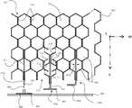
- FIG. 1is a perspective view of an exemplary wing box structure in accordance with the present disclosure
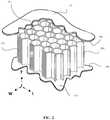
- FIG. 2is a perspective cut-away view of an exemplary section of the wing box structure of FIG. 1 taken along lines 2 - 2 ;
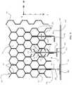
- FIG. 3is a top view of a cross-section of the wing box structure shown in FIG. 1 taken along lines 3 - 3 ;
- FIGS. 4A-4Cshow attachment rail embodiments in accordance with the present disclosure
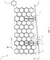
- FIG. 5is a top view of a cross-section of another exemplary core structure with variations of the attachment rails in accordance with the present disclosure
- FIGS. 6A and 6Billustrate an embodiment of a mounting device of one embodiment of an attachment rail in accordance with the present disclosure
- FIG. 7is a is a top view of a cross-section of another exemplary core structure with attachment rails in accordance with the present disclosure.
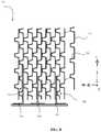
- FIG. 8is a top view of a cross-section of another exemplary core structure with attachment rails in accordance with the present disclosure.
- FIGS. 9A-9Cshow attachment rail embodiments in accordance with the present disclosure.
- FIG. 10is a cross-sectional view of the wing box structure shown in FIG. 3 taken along lines 10 - 10 .
- a composite core structureis typically made from plies of continuous fiber reinforced material.
- a composite corecan include a ribbon-based or a wrap-based architecture. Conventional methods of attaching core material to the surrounding structure add weight and cost as well an increase in cost of manufacturing.
- the core materialdoes not have any net edge facets, or flat edges, positioned next to surrounding structure, and/or may not have a structure arranged parallel to the adjacent support structure for purposes of attachment to the support structure.
- Fillersmay attach a non-uniform surface of the composite core to the surrounding support structure.
- Such fillersmay include foaming adhesives, epoxy, glass bead fillers, and the like to bridge the gap or cavity between the surrounding support structure and the composite core.
- FIG. 1illustrates an example of a potential structure which may utilize the embodiments described herein.
- the potential structure picturedis a wing torque box 100 .
- Other examples of structureinclude, but are not limited to, wind turbine blades, rotor blades, wing structures, and other structures which benefit from low weight applications. Some of these applications are outside of the aerospace field.
- the wing torque box 100may include a center box section 102 , a left-wing section 104 , and a right-wing section 106 .
- the wing torque box 100may be bound by an upper skin 108 and a lower skin 110 opposing the upper skin 108 .
- a forward end 112 of the wing torque box 100is bound by a forward spar (not shown) and an aft end 116 of the wing torque box 100 is bound by an aft spar 118 .
- the forward sparmay be arranged opposite the aft spar 118 .
- the wing torque box 100may also include first and second side ribs 120 , 122 arranged at opposite ends of the wing torque box 100 .
- the upper and lower skins 108 , 110are supported by an internal structure which may provide structural integrity.
- the wing torque box 100may bend without the skins 108 , 110 buckling. This may prevent the wing torque box 100 from collapsing and may also limit aerodynamic or flight safety issues that might otherwise occur.
- the skins 108 , 110may be stiffened with longitudinal and lateral elements.
- the internal stiffening supportsmay include core material comprising composite core structure and the elimination of both lateral and longitudinal internal stiffening elements.
- FIG. 2illustrates a perspective cut-away view of the wing torque box 100 of FIG. 1 along lines 2 - 2 .
- the interior of the wing torque box 100may comprise a composite core structure 200 between the upper and low skins 108 , 110 .
- the core structure 200may be have an upper surface 202 contoured to match an interior surface 204 of the upper skin 108 .
- the core structure 200may have a bottom surface (not shown, but arranged opposite the upper surface 202 ) to match an interior surface 208 of the lower skin 110 .
- the contouringmay be dependent on the support structure. For example, the contouring may differ between a wing box structure and a wind turbine blade.
- the core structure 200may comprise a ribbon corrugation.
- the ribbon corrugationas will be discussed later, may have a ribbon direction. In the embodiment shown, the ribbon direction may align with a length L of the core structure 200 .
- the width W of the core structure 200may be determined based at least in part on the number of ribbons attached together.
- the core structuremay comprise a collection of individually material wrapped cells.
- An overall thickness T of the core structure 200may vary along the width W and length L of the core structure 200 . For example, if the upper skin 108 , and in some embodiments lower skin 110 , vary in contour along an outer surface of the surrounding structure, the thickness T of the core structure 200 may vary as well. In other embodiments, if the upper skin 108 and/or lower skin 110 are substantially planar with a constant distance between them, then the thickness T of the core structure 200 may be consistent.
- the core structure 200may be a composite core structure.
- the core structuremay have a hexagonal-cell shape.
- the cellsmay have a size, for example, of about 1 ⁇ 4 inch to about 2 inches wide.
- the hexagonal cell-shapemay be larger than about 3 inches or smaller than about 1 ⁇ 4 inch.
- the core structure 200may further include a net edge core. Net edge core may be manufactured such that the location of individual cells is planned for in the final assembly. For example, the distances between end facets 210 may be predetermined such that an end facet 210 may mate with an edge of the surrounding structure and an opposing edge facet (not shown) of the core structure 200 may mate with the opposing edge of the surrounding structure.
- the end facet 210mates against a surface 300 of the torque box 100 .
- the torque box 100 in this exampleis merely exemplary as the core structure 200 may be used in a variety of applications as discussed previously.
- an end facet 210 amates with an end surface 302 of the left-wing section 104 .
- End surface 302may be referred to as a side rib, rib or mounting surface.
- An opposing end facet 210 bmates with an end surface 304 of the left-wing section 104 .
- the right-wing section(e.g., right-wing section 106 in FIG. 1 ) may have a similar structure.
- the core structure 200may not have any flat surfaces (e.g., end facets) to mate with surrounding walls of the torque box 100 along the length L of the core structure 200 (e.g., referred to as surrounding support structure). Therefore, in some embodiments, one or more rails 308 may attach the core structure 200 to the wing torque box 100 .
- the rails 308may enable the core structure 200 to provide strength and rigidity while reducing weight as compared to other attachment means.
- the rails 308may be integrated into the core structure 200 during fabrication of the core structure 200 or may be inserted afterwards. Both methods will be described herein.
- the rails 308also enable the core structure 200 to attach to non-uniform surfaces.
- the forward and aft walls 310 , 312are substantially perpendicular to the surface 300 . Not all mating surfaces in all applications will be perpendicular.
- the forward and aft walls 314 , 316 of the left-wing section 104are not perpendicular to the end surfaces 302 , 304 . Rather, the swept portion of the wing torque box 100 is offset at an angle ⁇ from the aft wall 312 .
- the rails 308may connect the core structure 200 to these offset walls 314 , 316 .
- Rails 308can also be used to attach the core structure 200 to surrounding surfaces that may be perpendicular to the length L of the core structure 200 , provided the ribbon direction is aligned with the length L.
- the core edges 318have insufficient bonding area to communicate forces from the core structure 200 to the surrounding walls 310 , 312 .
- the rails 308may bridge between the core edges 318 and the forward and aft walls 310 , 312 .
- FIGS. 4A-4Cillustrates different embodiments of the rail 308 .
- FIG. 4Aillustrates a tee rail 308 a .
- FIG. 4Billustrates an angle rail 308 b .
- FIG. 4Cillustrates a blade rail 308 c .
- the tee rail 308 amay provide a symmetric load path between the core structure 200 and the surrounding support surface. This may provide a high strength bond between the core structure 200 and the surrounding support surface.
- the angle rail 308 bmay be used to mate the core structure 200 to the surrounding support surface.
- the blade rail 308 cmay ease fabrication of the rail 308 c into the core structure 200 during fabrication of the core structure.
- the rails 308may comprise the same material as the core structure 200 .
- the rails 308may be the same prepreg used to build core structure 200 and form surrounding structure.
- the railsare precured before use in assembly.
- the rails 308may also be molded via a pultrusion process using reinforcing fibers.
- Each rail 308 a , 308 b , 308 chas a substantially planar core attachment leg 400 .
- the core attachment leg 400may have a width approximately equal to the thickness of the core structure 200 . In other embodiments, the core attachment leg 400 may have a width that is less than the thickness of the core structure 200 .
- Each rail 308 a , 308 b , 308 cmay have a mounting surface 402 .
- the mounting surface 402may be substantially planar and approximately the same width as the core attachment leg 400 . In some embodiments, the mounting surface 402 may be substantially narrower than the core attachment leg 400 . The moment in the rail may be reacted back into the cores structure and skins (e.g., skins 108 , 110 , FIGS.
- the mounting surface 402is shown arranged perpendicular to the core attachment leg 400 , but the mounting surface 402 may be transverse the core attachment leg 400 and potentially offset at a predetermined angle greater or less than 90 degrees. The moment be a direct result of the eccentricity between the surrounding structure and a centroid of the interface surface with the core. Typically, only shear in the T direction is reacted by mounting surface 402 .
- the tee rail 308 a and the angle rail 308 bmay have a joint 404 connecting the core attachment leg 400 and the mounting surface 402 .
- the joint 404may be a rigid joint with an angle predetermined when the rails 308 a , 308 b are manufactured. In other embodiments, the joint 404 may allow for some movement such that the angle may be set when the core structure 200 is assembled into surrounding support structure. In other embodiments, the joint 404 may be a flexible joint such as a hinge, spring joint, linkage, or the like. The flexible joint configuration may be useful, for example, when an angle between the ribbon direction and mating surface varies along a width of the core structure 200 .
- the blade rail 308 cmay have a separate mounting device 406 .
- the mounting device 406may have a mounting surface 402 and a joint 404 .
- the joint 404may form a Pi joint, so named because the mounting device 406 forms a shape similar to the letter Pi, ⁇ , in the Greek alphabet.
- the Pi jointmay comprise a groove 408 formed in the mounting surface 402 to accept the blade rail 308 c.
- FIG. 5illustrates a ribbon-based hexagonal core structure 500 with the three different rails 308 incorporated therein.
- the core structure 500may consist of separate ribbon corrugations 502 .
- the core structure 500may be constructed by placing composite material over mandrels (e.g., a hexagonal-shaped mandrel) or other tool components.
- the mandrelsmay be symmetric.
- the composite materialmay then be constrained on the mandrel during curing cycle (e.g., an oven cycle) to cure the composite material.
- the composite materialmay consist of any available prepreg material including epoxies, cyanite ester, polyimides, or lower end vinyl esters, and phenolic resin, with glass, carbon, quartz, and/or fibers.
- the curing cyclemay consist, for example, of placing the tooled ribbon corrugation in an oven to cure the material. Curing the material may consist of hardening the material to form a rigid, structural ribbon.
- the curing cyclemay include a thermosetting chemical reaction resulting in the creation of polymer chains and cross linking across ply boundaries. The mandrels may be extracted after the composite material is consolidated and cured.
- the interfaces between the ribbon corrugations 502are cured simultaneously with the ribbon corrugation 502 to form hexagonal cells 506 . This may enable crosslinking in the resin occurs and a ribbon joint 504 may be formed.
- the ribbon corrugations 502may be separately cured and adhesively bonded together.
- the ribbon corrugations 502may be bonded together using cured composite pieces with a hot film. The film may have a certain thickness and softens and cures during a cure cycle.
- the core attachment leg 400 of the rails 308 a 308 b , 308 cmay be aligned parallel with the length direction L of the core structure 500 .
- the angle rail 308 bmay be constructed prior to insertion between the ribbon corrugations 502 .
- the angle rail 308 bmay be inserted between the ribbon corrugations 502 as a step of or prior to the curing process of the core structure 500 .
- the core attachment leg 400 bmay become a part of the ribbon joint 504 .
- the core attachment leg 400 bmay be prepared for bonding and adhesive placed between the core attachment leg 400 b and the ribbon corrugation 502 , for example after the core structure 500 is cured.
- the preparationmay include sanding down the surface of the core attachment leg 400 b or applying one or more solvents on the core attachment leg 400 b to better accept adhesive and bond to the ribbon corrugation 502 .
- Other preparation methodsmay include grit blasting, peel ply, and the like.
- one or more hexagonal cells 506may be modified to accept a thickness t of the core attachment leg 400 .
- the thickness t of the planar leg of attachment rail integrated into the composite core 400may cause the hexagonal cells 506 and ribbon corrugation 502 to misalign as the core structure 500 is being manufactured.
- a disrupting thickness tmay be 1 to 5 plies thick, which may be in the range of about 0.0075 inches to about 0.0375 inches thick depending on the thickness of the individual plies.
- modified hexagonal cells 508may be incorporated into the fabrication stage to accept the planar leg of attachment rail integrated into the composite core 400 (e.g., attachment leg 400 b ).
- a modified cell 508may be fabricated using modified mandrels.
- a modified mandrelmay have a different cross-sectional shape or size as compared to the standard mandrel used for forming cells 506 .
- the core attachment leg 400may be integrated into the core structure 500 after the hexagonal core has been constructed.
- a ribbon joint 504may be removed from the core structure 500 in a location 510 where a rail 308 is to be incorporated.
- Partial ribbons 512 , 514may be formed onto the core attachment leg 400 of, in this embodiment, the tee rail 308 a .
- the partial ribbons 512 , 514may complete the trimmed hexagonal cells 516 .
- the partial ribbon 512may complete more than one trimmed hexagonal cell 516 .
- the partial ribbon 512may have an edge facet 518 and two legs 520 to complete the trimmed hexagonal cell 516 .
- the modified core attachment leg 400may be bonded into place.
- the modified core attachment leg 400may be moved into place using a spring action of the cantilevered portions of the trimmed hexagonal cell 516 to push back against the legs 514 of the partial ribbon 512 .
- a rail 308may be cured with the core structure 500 using the adjacent ribbon corrugations 502 and a partial modified mandrel.
- the rail 308may be a blade rail 308 c .
- the connection between the blade rail 308 c and the ribbon corrugations 502may then be formed during the curing process.
- Other rail configurationsmay also be cured with the core structure 500 such as the tee rail 308 a and the angle rail 308 b.
- the mounting surface 402may be secured to the surrounding support surface 524 using, for example, adhesive, fasteners, clips, or other coupled devices or methods.
- a mounting device 406may be adhered to the surrounding support surface 524 .
- the mounting device 406may have a mounting surface 402 with two prongs 530 transverse to the mounting surface 402 forming the groove 408 .
- the two prongs 530may be substantially perpendicular to the mounting surface 402 or may be offset at an angle ⁇ to the mounting surface 402 .
- the prongs 530may have a predetermined distance d between them forming the groove 408 .
- the predetermined distance dmay allow the groove 408 to accept an end 536 of the blade rail 308 c (see FIG. 5 ).
- the end 536 of the blade rail 308 cmay be, for example, pressed, adhered (e.g., using room templast material), fastened or otherwise coupled the mounting device 406 via the groove 408 .
- a depth of the groove 408may be determined by a length of the prongs 530 The prong length may be extended or increased to reinforce the end 536 of the blade rail 308 c and prevent bending of the blade rail 308 c.
- FIG. 7is a wrap-based hexagonal core structure 600 with rails 308 incorporated therein.
- the core structure 600may be separate wrapped polygons 604 assembled together to form the core structure 600 structure.
- the polygons 604may be formed by wrapping or winding composite material around a hexagonal mandrel and then assembling the mandrels in a desired pattern.
- the assembled mandrelsmay then be cured (e.g., in an oven cycle) to form the composite core structure 600 .
- the curing processmay cause the resin in the composite to cross-link and bond or otherwise adhere the separate polygons 604 together.
- the polygons 604may be formed and cured separately and then adhered or otherwise joined together to form the core structure 600 .
- the rails 308may be incorporated into the core structure 600 .
- modified mandrelsmay form modified cells 606 .
- the rails 308may be assembled with the modified cells 606 prior to the cure process such that the rails 308 and core structure 600 will be cured concurrently.
- the modified cells 606 and core structure 600may be cured without the rail 602 inserted.
- a modified mandrel or tool diemay be placed in the rail location to maintain dimensional integrity during the curing process.
- the polygons 604 , modified cells 606 , and rails 308may be separately cured and then assembled using the various techniques described herein.
- the core structure 600may incorporate extended cells to accept the rails 308 .
- modified mandrelsmay form extended cells, or cells that are longer in a one or more directions thereby forming an elongated hexagon shape.
- the extended cellmay then be split into sections (e.g., in half) to form the modified cell 606 .
- the rails 308may connect the core structure 600 to surrounding structure 608 .
- the surrounding structure 608may be a left-wing section (e.g. left-wing section 104 ) as seen in FIG. 1 or may be another surrounding structure as noted herein.
- the surrounding structure 608may not align with the core structure 600 .
- the surrounding structure 608may be offset at an angle ⁇ from a facet edge 610 of the core structure 600 . This may prevent the core structure 600 from directly coupling to the surrounding structure 608 without the use of fillers or adhesives. Instead, the mounting surface 402 of the rail 308 may couple the core structure 600 to the surrounding structure 608 .
- the mounting surface 402may be offset from the core attachment leg 400 to mate with the surrounding structure 608 by an angle ⁇ .
- the offset angle ⁇may be predetermined and incorporated into the manufacture of the rail 308 .
- the rail 308may comprise a somewhat flexible material and the offset angle ⁇ may be set during assembly of the apparatus.
- a hinge or other flexible jointmay be present at the joint 404 .
- the flexible joint 404may enable the angle ⁇ to be customized during the assembly process.
- FIG. 8depicts a ribbon-based flex hat core structure 700 with rails 308 arranged parallel to the core ribbon direction.
- the core structure 700may be configured similarly to the ribbon-based hexagonal core structure 500 except the flex hat-shaped ribbon corrugations 702 are a different shape.
- the flex shaped coreis typically cut with a band saw in parallel slices and then shaped or formed to a contour. In an application such as a through depth core wing box as shown in FIGS. 1, 2 and 3 , the core is profiled with a multi axis mill to represent the contour and the flexing capability of the configuration is not used.
- the shear strength of a flex hat core shape as compared to an equivalent density hexagonal coreis typically higher because of the number of folds per unit cell.
- the flex-hat shaped ribbon corrugation 702may be modified to incorporate one or more rails 308 .
- the hat portion 706 of the ribbon corrugation 702may be shortened to form a modified top hat cell 708 .
- Modified brim cells 710may also be used to incorporate one or more rails 308 into the core structure 700 .
- the rails 308may be incorporated during fabrication of the core structure 700 or may be inserted after the core structure 700 has been assembled.
- FIGS. 9A-9Cillustrates an alternative rail 908 embodiment.
- the rails 908 a , 908 b , 908 c shownmay be similar to the rail 308 a , 308 b , 308 c described previously.
- FIG. 9Aillustrates a tee rail 908 a .
- FIG. 9Billustrates an angle rail 908 b .
- FIG. 9Cillustrates a blade rail 908 c .
- a mounting device (not shown) for the blade rail 908 cmay be similar to the mounting device 406 described with reference to FIGS. 4-6 .
- the rail 908may include a core attachment leg 904 , mounting surface 906 and joint 907 .
- the rail 908may additionally have a notch 910 .
- the notch 910may interrupt the mounting surface 906 and create a void in the core attachment leg 904 .
- the notch 910may vary in one or more of size, shape and location along the mounting surface 906 .
- the notchmay provide additional space between the core and the adjacent structure.
- the notch 910opens a volume 912 in the space between the core 914 the adjacent structural member 916 surrounding the core 914 .
- the notch 910houses various objects 922 near the surrounding structure 916 .
- the various objects 922may include mount system lines, hydraulic lines, wiring, and similar features depending on the end use of the apparatus 918 .
- This volume 912 contained inside the apparatus 918may be accessible with a removable section 920 of the surrounding structure 916 .
- the removable section 920may reveal an opening 924 in the structure 916 .
- the interrupted mounting surface 906may attach to the structure 916 on either side of the opening 924 .
- the removable section 920may snap into place, or may be screwed, fastened, or otherwise removably affixed to the structure 916 .
- the notched rails 902 combined with the removable panel 920may enable a person to inspect the inside of the apparatus 918 and also inspect the various objects 922 placed within the notch 910 .
- the rail configurations described hereinmay be used with core designs not depicted herein including, for example, over-expanded OX core, reinforced stabilized core, double flex core, and noise reducing core.
- the rail configurationscan also be incorporated into a number of cores made from different materials as discussed herein.
- the term “aligned”means parallel, substantially parallel, or forming an angle of less than 35.0 degrees.
- the term “transverse”means perpendicular, substantially perpendicular, or forming an angle between 55.0 and 125.0 degrees.
- the term “length”means the longest dimension of an object.
- the term “width”means the dimension of an object from side to side. Often, the width of an object is transverse the object's length.
Landscapes
- Engineering & Computer Science (AREA)
- Mechanical Engineering (AREA)
- Aviation & Aerospace Engineering (AREA)
- Chemical & Material Sciences (AREA)
- Composite Materials (AREA)
- Moulding By Coating Moulds (AREA)
- Laminated Bodies (AREA)
Abstract
Description
Claims (20)
Priority Applications (5)
| Application Number | Priority Date | Filing Date | Title |
|---|---|---|---|
| US16/014,466US11167836B2 (en) | 2018-06-21 | 2018-06-21 | Devices and methods to attach composite core to a surrounding structure |
| GB2019962.6AGB2587740B (en) | 2018-06-21 | 2019-06-12 | Devices and methods to attach composite core to a surrounding structure |
| PCT/US2019/036827WO2019245827A1 (en) | 2018-06-21 | 2019-06-12 | Devices and methods to attach composite core to a surrounding structure |
| EP19822274.7AEP3810410A4 (en) | 2018-06-21 | 2019-06-12 | DEVICES AND METHODS FOR ATTACHING A COMPOSITE CORE TO SURROUNDING STRUCTURE |
| US17/453,803US11891172B2 (en) | 2018-06-21 | 2021-11-05 | Devices and methods to attach a composite core to a surrounding structure |
Applications Claiming Priority (1)
| Application Number | Priority Date | Filing Date | Title |
|---|---|---|---|
| US16/014,466US11167836B2 (en) | 2018-06-21 | 2018-06-21 | Devices and methods to attach composite core to a surrounding structure |
Related Child Applications (1)
| Application Number | Title | Priority Date | Filing Date |
|---|---|---|---|
| US17/453,803DivisionUS11891172B2 (en) | 2018-06-21 | 2021-11-05 | Devices and methods to attach a composite core to a surrounding structure |
Publications (2)
| Publication Number | Publication Date |
|---|---|
| US20190389557A1 US20190389557A1 (en) | 2019-12-26 |
| US11167836B2true US11167836B2 (en) | 2021-11-09 |
Family
ID=68980539
Family Applications (2)
| Application Number | Title | Priority Date | Filing Date |
|---|---|---|---|
| US16/014,466Active2039-09-24US11167836B2 (en) | 2018-06-21 | 2018-06-21 | Devices and methods to attach composite core to a surrounding structure |
| US17/453,803ActiveUS11891172B2 (en) | 2018-06-21 | 2021-11-05 | Devices and methods to attach a composite core to a surrounding structure |
Family Applications After (1)
| Application Number | Title | Priority Date | Filing Date |
|---|---|---|---|
| US17/453,803ActiveUS11891172B2 (en) | 2018-06-21 | 2021-11-05 | Devices and methods to attach a composite core to a surrounding structure |
Country Status (4)
| Country | Link |
|---|---|
| US (2) | US11167836B2 (en) |
| EP (1) | EP3810410A4 (en) |
| GB (1) | GB2587740B (en) |
| WO (1) | WO2019245827A1 (en) |
Cited By (3)
| Publication number | Priority date | Publication date | Assignee | Title |
|---|---|---|---|---|
| US12162606B1 (en) | 2023-09-08 | 2024-12-10 | Hamilton Sundstrand Corporation | Metal plated plastic ACM part with internal thermally adaptive structure |
| US20250084766A1 (en)* | 2023-09-08 | 2025-03-13 | Hamilton Sundstrand Corporation | Aircraft airfoil formed from thermally adaptive materials and including damping element, stiffening element, and a thermoelectric junction |
| US12384515B2 (en) | 2023-09-08 | 2025-08-12 | Hamilton Sundstrand Corporation | Airfoil formed of thermally adaptive materials and a thermoelectric junction |
Families Citing this family (1)
| Publication number | Priority date | Publication date | Assignee | Title |
|---|---|---|---|---|
| US11001375B2 (en)* | 2019-03-18 | 2021-05-11 | The Boeing Company | Structurally tunable cores |
Citations (28)
| Publication number | Priority date | Publication date | Assignee | Title |
|---|---|---|---|---|
| US3392225A (en)* | 1965-06-21 | 1968-07-09 | Frederick W Rohe | Method for installing molded-in inserts in sandwich panels |
| US4206895A (en)* | 1978-03-30 | 1980-06-10 | Olez Nejat A | Loop-tension joint |
| US4662587A (en) | 1981-09-30 | 1987-05-05 | The Boeing Company | Composite for aircraft wing and method of making |
| US5567500A (en) | 1991-08-07 | 1996-10-22 | Speciality Cellular Products Company | Composite honeycomb core structure comprising cell walls constructed of at least three unidirectional fiber layers or at least two unidirectional fiber layers and a random fiber layer |
| US6394722B1 (en)* | 1999-10-26 | 2002-05-28 | Swales Aerospace | Anti-distortion insert for mounting optical elements on a honeycomb panel |
| US6520706B1 (en) | 2000-08-25 | 2003-02-18 | Lockheed Martin Corporation | Composite material support structures with sinusoidal webs and method of fabricating same |
| US20040011927A1 (en)* | 2002-07-19 | 2004-01-22 | Christman David B. | Apparatuses and methods for joining structural members, such as composite structural members |
| US7037568B1 (en)* | 2003-07-15 | 2006-05-02 | Rogers Terry W | Joining member for mechanically joining a skin to a supporting rib |
| US20100006702A1 (en)* | 2007-05-11 | 2010-01-14 | The Boeing Company | Fastner-Free Primary Structural Joint for Sandwich Panels |
| US20100320325A1 (en)* | 2009-06-22 | 2010-12-23 | The Boeing Company | Skin Panel Joint for Improved Airflow |
| US20110095572A1 (en)* | 2009-10-28 | 2011-04-28 | Eurocopter | Honeycomb-structured floor panel for a vehicle, the panel incorporating a fastener element for fastening equipment of the vehicle |
| US20110135887A1 (en)* | 2009-12-04 | 2011-06-09 | The Boeing Company | Sandwich Structure Having Arrestment Feature and Method of Making the Same |
| US20110315300A1 (en)* | 2008-12-19 | 2011-12-29 | Saab Ab | Method of attaching elements by bonding |
| US20120234979A1 (en)* | 2011-03-15 | 2012-09-20 | The Boeing Company | Method and system for insulating frame member |
| US8544794B2 (en) | 2005-09-28 | 2013-10-01 | Airbus Operations Sas | Floor panel and installation for fixing layout elements comprising such panels |
| WO2014065718A1 (en) | 2012-10-22 | 2014-05-01 | Saab Ab | An integrated curved structure and winglet strength enhancement |
| US20140209744A1 (en) | 2013-01-26 | 2014-07-31 | The Boeing Company | Box Structures for Carrying Loads and Methods of Making the Same |
| US20140293497A1 (en)* | 2013-03-29 | 2014-10-02 | The Boeing Company | Method and Apparatus for Providing a Current Return Network in an Aircraft Structure |
| US20140295123A1 (en)* | 2013-03-28 | 2014-10-02 | Mitsubishi Aircraft Corporation | Method for repairing honeycomb core sandwich structural body and repaired product |
| US9156239B2 (en) | 2013-12-20 | 2015-10-13 | Bell Helicopter Textron Inc. | Method of manufacturing net edge core and a method of bonding net edge core to a substructure |
| US20150360764A1 (en)* | 2013-01-31 | 2015-12-17 | Airbus Operations Limited | Structual Assembly Joint |
| US20150362005A1 (en)* | 2014-06-17 | 2015-12-17 | John Meyers | Method for inserting and fixing a mounting insert into a lightweight sandwich panel as well as mounting insert |
| US9713913B2 (en) | 2010-02-04 | 2017-07-25 | Textron Innovations Inc. | Composite core and method of making same |
| US20180050788A1 (en) | 2016-08-16 | 2018-02-22 | The Boeing Company | Planked stringers that provide structural support for an aircraft wing |
| US20180201008A1 (en)* | 2017-01-18 | 2018-07-19 | The Boeing Company | Splices comprising honeycomb cores supported by tie clips and methods of forming thereof |
| US20180229443A1 (en)* | 2017-02-16 | 2018-08-16 | The Boeing Company | Efficient sub-structures |
| US20190232602A1 (en)* | 2016-07-25 | 2019-08-01 | Nolax Ag | Sandwich component, method for producing a sandwich component, and use of a sandwich component |
| US20200254713A1 (en)* | 2017-08-03 | 2020-08-13 | Lufthansa Technik Ag | Sandwich structure having an embedded connecting element |
Family Cites Families (214)
| Publication number | Priority date | Publication date | Assignee | Title |
|---|---|---|---|---|
| US1376785A (en) | 1920-11-04 | 1921-05-03 | Jacob P Sellmer | Aeroplane |
| US2501920A (en) | 1946-05-31 | 1950-03-28 | Steigel Mike | Folding airfoil |
| US2938680A (en) | 1957-07-02 | 1960-05-31 | North American Aviation Inc | Multiple position airfoil slat |
| US3049320A (en) | 1958-07-11 | 1962-08-14 | Charles J Fletcher | Annular wing aircraft |
| US3017139A (en) | 1959-02-02 | 1962-01-16 | Binder Wilhelm | Ring airfoil aircraft |
| US3310262A (en) | 1965-05-21 | 1967-03-21 | Augustine W Robins | Supersonic aircraft |
| US3360217A (en) | 1965-05-26 | 1967-12-26 | John C Trotter | Duct rotation system for vtol aircraft |
| US3415467A (en) | 1967-01-30 | 1968-12-10 | Joseph A. Barringer | Retrievable rocket with folded wings |
| US3438597A (en) | 1967-04-03 | 1969-04-15 | Witold A Kasper | Aircraft |
| US3564134A (en) | 1968-07-03 | 1971-02-16 | Us Navy | Two-camera remote drone control |
| US3916560A (en) | 1974-02-01 | 1975-11-04 | Joseph T Becker | Miniature aircraft and launcher unit therefor |
| US4008867A (en) | 1974-08-16 | 1977-02-22 | Kaniut Herbert M | Aircraft with safety tail unit |
| USD246168S (en) | 1976-05-17 | 1977-10-25 | Landrus Donald S | Man powered airplane |
| US4372507A (en) | 1977-03-02 | 1983-02-08 | Rockwell International Corporation | Selectively actuated flight simulation system for trainer aircraft |
| USD256347S (en) | 1977-05-26 | 1980-08-12 | Fairchild Industries, Inc. | Aircraft |
| USD256905S (en) | 1977-11-01 | 1980-09-16 | Fairchild Industries, Inc. | Aircraft |
| USD257338S (en) | 1978-11-09 | 1980-10-14 | Fairchild Industries, Inc. | Aircraft |
| USD264454S (en) | 1978-12-21 | 1982-05-18 | Snyder Stephen L | Jet aircraft |
| US4710708A (en) | 1981-04-27 | 1987-12-01 | Develco | Method and apparatus employing received independent magnetic field components of a transmitted alternating magnetic field for determining location |
| US4415132A (en) | 1981-11-25 | 1983-11-15 | The United States Of America As Represented By The Secretary Of The Air Force | Aircraft having variable incidence forward-swept wing |
| USD274510S (en) | 1982-02-18 | 1984-07-03 | Fairchild Industries, Inc. | Aircraft |
| USD281680S (en) | 1982-04-08 | 1985-12-10 | Charles Henderson | Airplane |
| US4569493A (en) | 1983-03-14 | 1986-02-11 | Grumman Aerospace Corporation | Integrated multi-role variable sweep wing aircraft |
| BR8601586A (en) | 1985-04-09 | 1986-12-30 | Dei Tech Inc | SUPER AGIL TACTICAL CACA AVIATION AND PILOT PROCESS |
| US4966802A (en)* | 1985-05-10 | 1990-10-30 | The Boeing Company | Composites made of fiber reinforced resin elements joined by adhesive |
| US4712352A (en)* | 1985-12-04 | 1987-12-15 | Low R Glenn | Modular construction system |
| USD298026S (en) | 1986-03-31 | 1988-10-11 | Judge Richard J | Aircraft |
| US4687691A (en) | 1986-04-28 | 1987-08-18 | United Technologies Corporation | Honeycomb spliced multilayer foam core aircraft composite parts and method for making same |
| DE3614618A1 (en)* | 1986-04-30 | 1987-11-05 | Messerschmitt Boelkow Blohm | SHELL STRUCTURE MADE OF FIBER REINFORCED PLASTIC |
| US5111400A (en) | 1987-03-16 | 1992-05-05 | Yoder Evan W | Automatic integrated real-time flight crew information system |
| US5118052A (en) | 1987-11-02 | 1992-06-02 | Albert Alvarez Calderon F | Variable geometry RPV |
| US4869443A (en) | 1988-03-21 | 1989-09-26 | Eidetics International, Inc. | Method of extending the performance of a specific jet aircraft |
| USD319805S (en) | 1988-05-13 | 1991-09-10 | Wiegert Gerald A | Aircraft |
| USD326255S (en) | 1988-09-23 | 1992-05-19 | Composite Industries Limited | Aircraft |
| US5039032A (en) | 1988-11-07 | 1991-08-13 | The Boeing Company | High taper wing tip extension |
| US4979699A (en) | 1989-05-26 | 1990-12-25 | Grumman Aerospace Corporation | Flight control augmentation inlet device |
| USD323315S (en) | 1989-05-30 | 1992-01-21 | The Ishida Foundation | Dual mode air vehicle |
| US5115996A (en) | 1990-01-31 | 1992-05-26 | Moller International, Inc. | Vtol aircraft |
| USD332080S (en) | 1990-02-23 | 1992-12-29 | Northrop Corporation | Aircraft |
| US5274846A (en) | 1990-06-12 | 1994-01-04 | Hpi Health Protection, Inc. | Cushion having multilayer closed cell structure |
| EP0539464A4 (en) | 1990-07-25 | 1994-11-02 | Sadleir Vtol Aircraft Co Pty L | Thrust unit for vtol aircraft |
| US5574648A (en) | 1990-10-09 | 1996-11-12 | Pilley; Harold R. | Airport control/management system using GNSS-based methods and equipment for the control of surface and airborne traffic |
| US5192037A (en) | 1991-08-23 | 1993-03-09 | Mcdonnell Douglas Corporation | Double-pivoting deployment system for aerosurfaces |
| US5379969A (en) | 1992-01-30 | 1995-01-10 | The Boeing Company | Hydraulic actuator with mechanical lock and installation |
| AU121271S (en) | 1992-10-23 | 1994-08-15 | Eagle Aircraft Pty Ltd | Aircraft |
| JP2680246B2 (en) | 1993-09-17 | 1997-11-19 | 徳三 廣瀬 | Flying object |
| USD356990S (en) | 1993-10-15 | 1995-04-04 | Northrop Grumman Corporation | Aircraft |
| US5496001A (en) | 1994-01-28 | 1996-03-05 | Skow; Andrew | T-38 aircraft modified with an F-5 wing |
| DE19529706C2 (en)* | 1995-08-11 | 2001-08-02 | Deutsch Zentr Luft & Raumfahrt | Wing structure, in particular for an aircraft |
| DE19529476C2 (en)* | 1995-08-11 | 2000-08-10 | Deutsch Zentr Luft & Raumfahrt | Wing with shear-resistant wing shells made of fiber composite materials for aircraft |
| US5716032A (en) | 1996-04-22 | 1998-02-10 | United States Of America As Represented By The Secretary Of The Army | Unmanned aerial vehicle automatic landing system |
| USD392937S (en) | 1996-07-19 | 1998-03-31 | Aero Challenge | Two seater amphibious aircraft |
| US5890079A (en) | 1996-12-17 | 1999-03-30 | Levine; Seymour | Remote aircraft flight recorder and advisory system |
| US5842666A (en) | 1997-02-21 | 1998-12-01 | Northrop Grumman Coporation | Laminar supersonic transport aircraft |
| US5984229A (en) | 1997-06-02 | 1999-11-16 | Boeing North American, Inc. | Extremely short takeoff and landing of aircraft using multi-axis thrust vectoring |
| DE19730381C1 (en)* | 1997-07-16 | 1998-08-20 | Deutsch Zentr Luft & Raumfahrt | Structural element, e.g wing panel for aircraft |
| DE19731604C2 (en)* | 1997-07-18 | 2002-04-11 | Dwa Deutsche Waggonbau Gmbh | Sandwich panel with integrated profile, especially for vehicle construction |
| US6147980A (en) | 1997-11-28 | 2000-11-14 | Motorola, Inc. | Avionics satellite based data message routing and delivery system |
| US6260797B1 (en) | 1998-01-13 | 2001-07-17 | Science Applications International Corporation | Transformable gun launched aero vehicle |
| US5927645A (en) | 1998-01-15 | 1999-07-27 | Northrop Grumman Corporation | Shovel nose pneumatic vortex control |
| USD446764S1 (en) | 1998-03-30 | 2001-08-21 | Aktsionernoe Obschestvo Otkrytogo Tipa Taganrogsky Aviatsionny Nauchno-Tekhnichesky Komplex Imeni Gm Berieva | Light amphibian |
| US6176451B1 (en) | 1998-09-21 | 2001-01-23 | Lockheed Martin Corporation | Utilizing high altitude long endurance unmanned airborne vehicle technology for airborne space lift range support |
| DE19845863B4 (en)* | 1998-10-05 | 2005-05-19 | Deutsches Zentrum für Luft- und Raumfahrt e.V. | Structural element with large unidirectional stiffness |
| USD418805S (en) | 1998-11-24 | 2000-01-11 | Sikorsky Aircraft Corporation | Unmanned multi-mode vertical take off and landing aircraft |
| USD418105S (en) | 1999-01-26 | 1999-12-28 | Michael Margaritoff | Six seater twin engine aircraft |
| US7570214B2 (en) | 1999-03-05 | 2009-08-04 | Era Systems, Inc. | Method and apparatus for ADS-B validation, active and passive multilateration, and elliptical surviellance |
| US7429950B2 (en) | 1999-03-05 | 2008-09-30 | Era Systems Corporation | Method and apparatus to extend ADS performance metrics |
| US6885340B2 (en) | 2000-02-29 | 2005-04-26 | Rannoch Corporation | Correlation of flight track data with other data sources |
| US6633259B1 (en) | 1999-03-05 | 2003-10-14 | Rannuch Corporation | Method and apparatus for improving utility of automatic dependent surveillance |
| US7782256B2 (en) | 1999-03-05 | 2010-08-24 | Era Systems Corporation | Enhanced passive coherent location techniques to track and identify UAVs, UCAVs, MAVs, and other objects |
| USD439876S1 (en) | 1999-04-22 | 2001-04-03 | Zakrytoe Actsionernoe Obshchestvo “Otdelenie morskikh sistem OKB im. P.O. Sukhogo” | Supersonic aircraft with in-flight refueling system |
| US6173159B1 (en) | 1999-06-25 | 2001-01-09 | Harris Corporation | Wireless spread spectrum ground link-based aircraft data communication system for updating flight management files |
| USD458577S1 (en) | 1999-10-25 | 2002-06-11 | Charles Kochen Han | Spy plane |
| USD431522S (en) | 1999-12-29 | 2000-10-03 | Honda Giken Kogyo Kabushiki Kaisha | Airplane |
| US6338011B1 (en) | 2000-01-11 | 2002-01-08 | Solipsys Corporation | Method and apparatus for sharing vehicle telemetry data among a plurality of users over a communications network |
| JP2003521714A (en) | 2000-02-02 | 2003-07-15 | ノキア コーポレイション | Position calculation receiver |
| US20020066825A1 (en) | 2000-04-13 | 2002-06-06 | Miralles Carlos T. | Payload delivery system |
| US6392213B1 (en) | 2000-10-12 | 2002-05-21 | The Charles Stark Draper Laboratory, Inc. | Flyer assembly |
| MXPA03003479A (en) | 2000-10-17 | 2003-07-14 | United Parcel Service Inc | Integrated datalinks in a surveillance receiver. |
| USD464604S1 (en) | 2000-12-07 | 2002-10-22 | Andrey Mikhailovich Karklin | Aeroplane |
| USD468255S1 (en) | 2000-12-21 | 2003-01-07 | Raghaven Gopalaswami | Aerospace vehicle |
| JPWO2003004352A1 (en) | 2001-07-06 | 2004-10-21 | セイコーエプソン株式会社 | Airship system |
| US6677888B2 (en) | 2001-08-09 | 2004-01-13 | Honeywell International, Inc. | Secure aircraft communications addressing and reporting system (ACARS) |
| US6681158B2 (en) | 2001-09-21 | 2004-01-20 | Garmin At, Inc. | Uninterruptable ADS-B system for aircraft tracking |
| US6995688B2 (en) | 2001-09-24 | 2006-02-07 | Reynolds James S | Method and apparatus for thwarting attempts to hijack aircraft and for responding to other aircraft emergencies |
| ITMI20012170A1 (en) | 2001-10-18 | 2003-04-18 | Aermacchi S P A | IMPROVED AERODYNAMIC AIRCRAFT CONFIGURATION |
| US20030094536A1 (en) | 2001-10-25 | 2003-05-22 | Labiche Mitchell G. | Flyable automobile |
| US6799114B2 (en) | 2001-11-20 | 2004-09-28 | Garmin At, Inc. | Systems and methods for correlation in an air traffic control system of interrogation-based target positional data and GPS-based intruder positional data |
| EP1338506A1 (en) | 2002-02-15 | 2003-08-27 | Fairchild Dornier GmbH | Airplane wing with slat and Krueger flap |
| USD467217S1 (en) | 2002-02-27 | 2002-12-17 | Michael J. Andreyko | Airplane |
| US20040048027A1 (en)* | 2002-09-06 | 2004-03-11 | Hayes Michael W. | Honeycomb cores for aerospace applications |
| US7040210B2 (en) | 2003-02-18 | 2006-05-09 | Lockheed Martin Corporation | Apparatus and method for restraining and releasing a control surface |
| US7410124B2 (en) | 2003-02-21 | 2008-08-12 | Aai Corporation | Lightweight air vehicle and pneumatic launcher |
| US7343232B2 (en) | 2003-06-20 | 2008-03-11 | Geneva Aerospace | Vehicle control system including related methods and components |
| US7070146B2 (en) | 2003-08-29 | 2006-07-04 | Supersonic Aerospace International, Llc | Aircraft thickness/camber control device for low sonic boom |
| US6935592B2 (en) | 2003-08-29 | 2005-08-30 | Supersonic Aerospace International, Llc | Aircraft lift device for low sonic boom |
| US7130741B2 (en) | 2003-10-23 | 2006-10-31 | International Business Machines Corporation | Navigating a UAV with a remote control device |
| US6942178B2 (en) | 2003-11-11 | 2005-09-13 | Supersonic Aerospace International, Llc | Mach weighted area ruling for supersonic vehicles |
| GB2412027B (en) | 2004-03-08 | 2007-04-11 | Raytheon Systems Ltd | Secondary radar message decoding |
| US7252263B1 (en) | 2004-07-29 | 2007-08-07 | Hawker Beechcraft Corporation | Design methods and configurations for supersonic aircraft |
| US7840317B2 (en) | 2004-08-16 | 2010-11-23 | Matos Jeffrey A | Method and system for controlling a hijacked aircraft |
| US7307579B2 (en) | 2004-11-03 | 2007-12-11 | Flight Safety Technologies, Inc. | Collision alerting and avoidance system |
| US7228232B2 (en) | 2005-01-24 | 2007-06-05 | International Business Machines Corporation | Navigating a UAV with obstacle avoidance algorithms |
| US7669372B2 (en)* | 2005-02-07 | 2010-03-02 | T. Clear Corporation | Structural insulated panel and panel joint |
| US7269513B2 (en) | 2005-05-03 | 2007-09-11 | Herwitz Stanley R | Ground-based sense-and-avoid display system (SAVDS) for unmanned aerial vehicles |
| US7789339B2 (en) | 2005-07-07 | 2010-09-07 | Sommer Geoffrey S | Modular articulated-wing aircraft |
| US20080217472A1 (en) | 2005-10-03 | 2008-09-11 | Rocket Racing, Inc. | Rocket-powered vehicle racing reality system |
| DE102005057907B4 (en)* | 2005-12-02 | 2012-03-22 | Eurocopter Deutschland Gmbh | Aircraft pressure cabin door made of fiber composite material |
| US20070222665A1 (en) | 2006-03-07 | 2007-09-27 | Koeneman Robert L | Airborne Situational Awareness System |
| US8838289B2 (en) | 2006-04-19 | 2014-09-16 | Jed Margolin | System and method for safely flying unmanned aerial vehicles in civilian airspace |
| US7581702B2 (en) | 2006-06-09 | 2009-09-01 | Insitu, Inc. | Wirelessly controlling unmanned aircraft and accessing associated surveillance data |
| US20090222148A1 (en) | 2006-06-21 | 2009-09-03 | Calspan Corporation | Autonomous Outer Loop Control of Man-Rated Fly-By-Wire Aircraft |
| US7551989B2 (en) | 2006-06-21 | 2009-06-23 | Calspan Corporation | Autonomous outer loop control of man-rated fly-by-wire aircraft |
| US7991516B2 (en) | 2006-09-03 | 2011-08-02 | Matos Jeffrey A | Apparatus for airfield management |
| US7835824B2 (en) | 2006-09-06 | 2010-11-16 | Matos Jeffrey A | Systems and methods for detecting and managing the unauthorized use of a unmanned aircraft |
| AU2007354885B2 (en) | 2006-12-06 | 2011-10-20 | Honeywell International, Inc. | Methods, apparatus and systems for enhanced synthetic vision and multi-sensor data fusion to improve operational capabilities of unmanned aerial vehicles |
| US20080158041A1 (en) | 2006-12-29 | 2008-07-03 | Tommasi & Tommasi America, Llc | Airport Surface Detector and Control System |
| US7637686B2 (en)* | 2007-03-02 | 2009-12-29 | The Boeing Company | Swivel fitting attachment apparatus |
| US7912593B2 (en) | 2007-04-02 | 2011-03-22 | Aviation Communication & Surveillance Systems, Llc | Merging and spacing speed target calculation |
| US8089033B2 (en) | 2007-06-18 | 2012-01-03 | Bae Systems Information And Electronic Systems Integration Inc. | POD launched unmanned air vehicle |
| US7946527B2 (en) | 2007-09-10 | 2011-05-24 | Alan Glen Holmes | Aircraft with fixed, swinging and folding wings |
| US8376279B2 (en) | 2008-01-23 | 2013-02-19 | Aurora Flight Sciences Corporation | Inflatable folding wings for a very high altitude aircraft |
| USD613202S1 (en) | 2008-06-12 | 2010-04-06 | Icon Aircraft, Inc. | Amphibious sport aircraft |
| US9446840B2 (en) | 2008-07-01 | 2016-09-20 | The Boeing Company | Systems and methods for alleviating aircraft loads with plasma actuators |
| US20100051742A1 (en) | 2008-07-22 | 2010-03-04 | Terrafugia, Inc,; | Folding Wing & Locking Mechanism |
| USD621774S1 (en) | 2008-07-25 | 2010-08-17 | Matthias Betsch | Airplane |
| US8089034B2 (en) | 2009-04-17 | 2012-01-03 | Itt Manufacturing Enterprises, Inc. | Mechanism for folding, sweeping, and locking vehicle wings about a single pivot |
| US8444082B1 (en) | 2009-08-19 | 2013-05-21 | The United States Of America, As Represented By The Secretary Of The Navy | High performance ‘X’-configuration airplane for storage and launch from a tubular container |
| FR2951434B1 (en) | 2009-10-20 | 2012-03-09 | Airbus Operations Sas | HORIZONTAL AIRCRAFT EMPLOYMENT WITH AN ATTACHMENT APEX |
| US8448893B2 (en) | 2009-10-26 | 2013-05-28 | Aerion Corporation | Laminar flow wing optimized for transonic cruise aircraft |
| USD690254S1 (en) | 2009-12-23 | 2013-09-24 | OOO “KB Sovremennye Aviatsionnye Tehnologii” | Acrobatic aircraft |
| USD651156S1 (en) | 2010-03-31 | 2011-12-27 | Aurora Flight Sciences Corporation | Unmanned air-launched cargo glider |
| US8342447B2 (en) | 2010-06-15 | 2013-01-01 | The Boeing Company | Morphing control surface transition |
| WO2012006711A1 (en) | 2010-07-16 | 2012-01-19 | Vital Alert Communication | Portable through-the-earth radio |
| RU2440916C1 (en) | 2010-07-28 | 2012-01-27 | Открытое акционерное общество "ОКБ Сухого" | Aircraft in integral aerodynamic configuration |
| US8387913B2 (en) | 2010-08-12 | 2013-03-05 | Abe Karem | Compact aircraft wing folding systems and methods |
| ITTO20110122A1 (en) | 2011-02-14 | 2012-08-15 | Alenia Aermacchi Spa | AIRCRAFT CONFIGURATION TO IMPROVED AERODYNAMIC PERFORMANCES. |
| US9527596B1 (en) | 2011-03-01 | 2016-12-27 | Richard D. Adams | Remote controlled aerial reconnaissance vehicle |
| USD649506S1 (en) | 2011-04-04 | 2011-11-29 | Luca Morelli | Airplane |
| USD717227S1 (en) | 2011-04-12 | 2014-11-11 | Lisa Airplanes | Amphibian aeroplane |
| US8876039B2 (en) | 2011-05-03 | 2014-11-04 | Stark Aerospace, Inc. | Folding wing for aircraft |
| USD665331S1 (en) | 2011-11-09 | 2012-08-14 | Unmanned Systems, Inc. | Unmanned aerial vehicle |
| FR2990409B1 (en)* | 2012-05-09 | 2015-01-30 | Airbus Operations Sas | VENTRAL BEAM OF AN AIRCRAFT |
| BG111231A (en) | 2012-06-07 | 2013-12-31 | КРЪСТЕВ ИванKrustev Ivan | Road aircraft |
| CN104540733B (en) | 2012-06-07 | 2016-09-21 | 威罗门飞行公司 | System for detachably coupling an unmanned aerial vehicle within a launch tube |
| US10669021B2 (en) | 2012-09-14 | 2020-06-02 | Textron Innovations Inc. | Method of optimizing and customizing rotor blade structural properties by tailoring large cell composite core and a rotor blade incorporating the same |
| US9156476B2 (en) | 2012-10-02 | 2015-10-13 | Trevor O'Neill | System and method for remote control of unmanned vehicles |
| US9149999B2 (en) | 2012-10-30 | 2015-10-06 | Bell Helicopter Textron Inc. | Method of repairing, splicing, joining, machining, and stabilizing honeycomb core using pourable structural foam and a structure incorporating the same |
| US9031559B2 (en) | 2012-11-20 | 2015-05-12 | At&T Mobility Ii Llc | Facilitation of adaptive traffic flow management by a power-limited mobile device |
| US9120255B2 (en) | 2013-03-15 | 2015-09-01 | Bell Helicopter Textron Inc. | Composite core and method of making same |
| KR20150132459A (en) | 2013-03-15 | 2015-11-25 | 키사, 아이엔씨. | Ehf secure communication device |
| USD734402S1 (en) | 2013-04-29 | 2015-07-14 | Vladimir Reznik | Radio controlled airplane |
| USD706678S1 (en) | 2013-05-13 | 2014-06-10 | Precisionhawk Inc. | Unmanned aerial vehicle |
| GB2514770B (en) | 2013-06-03 | 2015-08-05 | Lockheed Corp | Launched air vehicle system |
| USD713321S1 (en) | 2013-07-09 | 2014-09-16 | Empirical Systems Aerospace, Inc. | Air vehicle having rotating wings |
| USD739807S1 (en) | 2013-07-15 | 2015-09-29 | Icon Aircraft, Inc. | Amphibious sport aircraft |
| USD713774S1 (en) | 2013-07-15 | 2014-09-23 | Icon Aircraft, Inc. | Amphibious sport aircraft with wings stowed |
| USD708563S1 (en) | 2013-07-17 | 2014-07-08 | Rosemount Aerospace Inc. | Hand launched fixed wing aircraft |
| US9749878B2 (en) | 2013-07-31 | 2017-08-29 | Blackberry Limited | System and method for managing communications for two networks in a communication device |
| USD710782S1 (en) | 2013-09-05 | 2014-08-12 | Darold B. Cummings | Air vehicle having rotatable and retractable pairs of wings |
| US9776719B2 (en) | 2013-09-05 | 2017-10-03 | Raytheon Company | Air-launchable container for deploying air vehicle |
| USD803724S1 (en) | 2013-09-23 | 2017-11-28 | Dylan T X Zhou | Amphibious unmanned vertical takeoff and landing aircraft |
| USD809970S1 (en) | 2013-09-23 | 2018-02-13 | Dylan T X Zhou | Amphibious unmanned vertical takeoff and landing aircraft |
| USD801856S1 (en) | 2013-09-23 | 2017-11-07 | Dylan T X Zhou | Amphibious unmanned vertical takeoff and landing aircraft |
| US9457537B1 (en)* | 2013-11-26 | 2016-10-04 | Hrl Laboratories, Llc | Methods for embedding fasteners in an open cellular sandwich structure |
| US9090026B2 (en) | 2013-12-20 | 2015-07-28 | Bell Helicopter Textron Inc. | Method of splicing composite core |
| US20150293845A1 (en) | 2014-04-11 | 2015-10-15 | Advanced Micro Devices, Inc. | Multi-level memory hierarchy |
| US10124890B2 (en) | 2014-04-11 | 2018-11-13 | Dronetechuav Corporation | Modular nacelles to provide vertical takeoff and landing (VTOL) capabilities to fixed wing aerial vehicles, and associated systems and methods |
| US9783284B2 (en) | 2014-05-20 | 2017-10-10 | The Boeing Company | Rotary drive assembly for wing tip |
| USD743868S1 (en) | 2014-06-26 | 2015-11-24 | Darold B. Cummings | Vertical takeoff and landing airplane |
| US9760094B2 (en) | 2014-10-08 | 2017-09-12 | The Boeing Company | Distributed collaborative operations processor systems and methods |
| FR3028498B1 (en) | 2014-11-14 | 2018-06-01 | Airbus Operations | DEVICE FOR CONTROLLING A PUSHING REGIME OF AT LEAST ONE AIRCRAFT ENGINE. |
| EP3040270B1 (en) | 2014-12-31 | 2020-09-30 | Rolls-Royce North American Technologies, Inc. | Fluid-vectoring system |
| CN204998752U (en) | 2015-01-04 | 2016-01-27 | 北京零零无限科技有限公司 | Folding unmanned aerial vehicle |
| US20160266733A1 (en) | 2015-03-11 | 2016-09-15 | Case Global, Inc. | Event and staff management systems and methods |
| US10843434B2 (en) | 2015-06-22 | 2020-11-24 | Sikorsky Aircraft Corporation | Core material for composite structures |
| US10232938B2 (en) | 2015-07-01 | 2019-03-19 | W.Morrison Consulting Group, Inc. | Unmanned supply delivery aircraft |
| GB2534435B (en) | 2015-08-13 | 2017-09-06 | Wirth Res Ltd | An unmanned aerial vehicle with folding wing arrangement |
| US9507346B1 (en) | 2015-11-04 | 2016-11-29 | Zoox, Inc. | Teleoperation system and method for trajectory modification of autonomous vehicles |
| US10401852B2 (en) | 2015-11-04 | 2019-09-03 | Zoox, Inc. | Teleoperation system and method for trajectory modification of autonomous vehicles |
| US9555873B1 (en) | 2015-11-11 | 2017-01-31 | Area-I Inc. | Aerial vehicle with deployable components |
| US9777502B2 (en) | 2015-12-18 | 2017-10-03 | Amazon Technologies, Inc. | Multi-level fulfillment center for unmanned aerial vehicles |
| US10328658B2 (en) | 2015-12-29 | 2019-06-25 | Bell Helicopter Textron Inc. | Composite core with non-traditional geometries |
| US9725155B2 (en) | 2015-12-30 | 2017-08-08 | General Electric Company | Method and system for open rotor engine fuselage protection |
| US10493936B1 (en) | 2016-01-22 | 2019-12-03 | State Farm Mutual Automobile Insurance Company | Detecting and responding to autonomous vehicle collisions |
| US10124880B1 (en) | 2016-02-03 | 2018-11-13 | Lockheed Martin Corporation | Rotatable control surface assembly for an unmanned aerial vehicle |
| US10399285B2 (en)* | 2016-02-08 | 2019-09-03 | Bell Helicopter Textron Inc. | Composite wing structure and methods of manufacture |
| US10046850B2 (en) | 2016-04-01 | 2018-08-14 | Lockheed Martin Corporation | Aircraft wing shift device |
| US9505484B1 (en) | 2016-04-11 | 2016-11-29 | Nasser M. Al-Sabah | Modular aircraft system |
| USD810621S1 (en) | 2016-04-12 | 2018-02-20 | King Saud University | Aerial vehicle |
| USD807273S1 (en) | 2016-04-15 | 2018-01-09 | Johann Schwöller | Glider |
| USD795160S1 (en) | 2016-04-15 | 2017-08-22 | Johann Schwöller | Airplane |
| EP3254956B1 (en) | 2016-06-09 | 2020-01-29 | Airbus Operations GmbH | Foldable wing with an actuator arrangement |
| US10974809B2 (en) | 2016-06-23 | 2021-04-13 | Sierra Nevada Corporation | Air-launched unmanned aerial vehicle |
| US10220935B2 (en)* | 2016-09-13 | 2019-03-05 | The Boeing Company | Open-channel stiffener |
| USD808328S1 (en) | 2016-09-14 | 2018-01-23 | Bell Helicopter Textron Inc. | Foldable tiltrotor aircraft |
| US10710710B2 (en) | 2016-10-27 | 2020-07-14 | International Business Machines Corporation | Unmanned aerial vehicle (UAV) compliance using standard protocol requirements and components to enable identifying and controlling rogue UAVS |
| USD813143S1 (en) | 2016-11-04 | 2018-03-20 | Aerovironment, Inc. | Vertical take-off and landing (VTOL) winged air vehicle with complementary angled rotors |
| US10207793B2 (en) | 2016-11-30 | 2019-02-19 | Bell Helicopter Textron Inc. | Rotor blade having variable twist |
| JP6819490B2 (en) | 2017-02-02 | 2021-01-27 | 株式会社豊田自動織機 | Remote control system for industrial vehicles, industrial vehicles, remote control devices, remote control programs for industrial vehicles and remote control methods for industrial vehicles |
| JP6614178B2 (en) | 2017-02-16 | 2019-12-04 | トヨタ自動車株式会社 | Vehicle communication system and vehicle control apparatus |
| US9815545B1 (en) | 2017-02-28 | 2017-11-14 | Steering Financial Ltd. | Aerodynamic lifting system |
| CN106970648B (en) | 2017-04-19 | 2019-05-14 | 北京航空航天大学 | Unmanned plane multi-goal path plans combined method for searching under the environment of city low latitude |
| USD824804S1 (en) | 2017-07-06 | 2018-08-07 | Yu Tian | Hybrid VTOL fixed-wing drone |
| US10386836B2 (en) | 2017-07-07 | 2019-08-20 | Zoox, Inc. | Interactions between vehicle and teleoperations system |
| US20210061027A1 (en) | 2017-10-26 | 2021-03-04 | Applied Mechatronic Products | Apparatus and method for vehicular monitoring, analysis, and control |
| US10393527B2 (en) | 2017-12-20 | 2019-08-27 | National Chung Shan Institute Of Science And Technology | UAV navigation obstacle avoidance system and method thereof |
| US10706948B2 (en) | 2018-07-12 | 2020-07-07 | Allegro Microsystems, Llc | Multi-level memory safety of a sensor integrated circuit |
| WO2020035996A1 (en) | 2018-08-17 | 2020-02-20 | ソニー株式会社 | Information processing device, information processing system, information processing method, and program |
| WO2020145803A1 (en) | 2019-01-11 | 2020-07-16 | 엘지전자 주식회사 | Method for transmitting feedback information in wireless communication system |
| US10932301B2 (en) | 2019-03-28 | 2021-02-23 | Lg Electronics Inc. | Method of operating transmitting UE in relation to RLF reporting of the transmitting UE which has established link after random access procedure in wireless communication system |
| DE112020001663T5 (en) | 2019-03-29 | 2022-03-24 | Intel Corporation | Autonomous Vehicle System |
| US20200404569A1 (en) | 2019-06-19 | 2020-12-24 | Lg Electronics Inc. | Method and apparatus for switching a transmission route of data in wireless communication system |
| US11713060B2 (en) | 2020-09-18 | 2023-08-01 | Guident Ltd. | Systems and methods for remote monitoring of a vehicle, robot or drone |
- 2018
- 2018-06-21USUS16/014,466patent/US11167836B2/enactiveActive
- 2019
- 2019-06-12WOPCT/US2019/036827patent/WO2019245827A1/ennot_activeCeased
- 2019-06-12EPEP19822274.7Apatent/EP3810410A4/enactivePending
- 2019-06-12GBGB2019962.6Apatent/GB2587740B/enactiveActive
- 2021
- 2021-11-05USUS17/453,803patent/US11891172B2/enactiveActive
Patent Citations (29)
| Publication number | Priority date | Publication date | Assignee | Title |
|---|---|---|---|---|
| US3392225A (en)* | 1965-06-21 | 1968-07-09 | Frederick W Rohe | Method for installing molded-in inserts in sandwich panels |
| US4206895A (en)* | 1978-03-30 | 1980-06-10 | Olez Nejat A | Loop-tension joint |
| US4662587A (en) | 1981-09-30 | 1987-05-05 | The Boeing Company | Composite for aircraft wing and method of making |
| US5567500A (en) | 1991-08-07 | 1996-10-22 | Speciality Cellular Products Company | Composite honeycomb core structure comprising cell walls constructed of at least three unidirectional fiber layers or at least two unidirectional fiber layers and a random fiber layer |
| US6394722B1 (en)* | 1999-10-26 | 2002-05-28 | Swales Aerospace | Anti-distortion insert for mounting optical elements on a honeycomb panel |
| US6520706B1 (en) | 2000-08-25 | 2003-02-18 | Lockheed Martin Corporation | Composite material support structures with sinusoidal webs and method of fabricating same |
| US20040011927A1 (en)* | 2002-07-19 | 2004-01-22 | Christman David B. | Apparatuses and methods for joining structural members, such as composite structural members |
| US7037568B1 (en)* | 2003-07-15 | 2006-05-02 | Rogers Terry W | Joining member for mechanically joining a skin to a supporting rib |
| US8544794B2 (en) | 2005-09-28 | 2013-10-01 | Airbus Operations Sas | Floor panel and installation for fixing layout elements comprising such panels |
| US20100006702A1 (en)* | 2007-05-11 | 2010-01-14 | The Boeing Company | Fastner-Free Primary Structural Joint for Sandwich Panels |
| US20110315300A1 (en)* | 2008-12-19 | 2011-12-29 | Saab Ab | Method of attaching elements by bonding |
| US20100320325A1 (en)* | 2009-06-22 | 2010-12-23 | The Boeing Company | Skin Panel Joint for Improved Airflow |
| US20110095572A1 (en)* | 2009-10-28 | 2011-04-28 | Eurocopter | Honeycomb-structured floor panel for a vehicle, the panel incorporating a fastener element for fastening equipment of the vehicle |
| US20110135887A1 (en)* | 2009-12-04 | 2011-06-09 | The Boeing Company | Sandwich Structure Having Arrestment Feature and Method of Making the Same |
| US9713913B2 (en) | 2010-02-04 | 2017-07-25 | Textron Innovations Inc. | Composite core and method of making same |
| US20120234979A1 (en)* | 2011-03-15 | 2012-09-20 | The Boeing Company | Method and system for insulating frame member |
| WO2014065718A1 (en) | 2012-10-22 | 2014-05-01 | Saab Ab | An integrated curved structure and winglet strength enhancement |
| US20140209744A1 (en) | 2013-01-26 | 2014-07-31 | The Boeing Company | Box Structures for Carrying Loads and Methods of Making the Same |
| US20150360764A1 (en)* | 2013-01-31 | 2015-12-17 | Airbus Operations Limited | Structual Assembly Joint |
| US20140295123A1 (en)* | 2013-03-28 | 2014-10-02 | Mitsubishi Aircraft Corporation | Method for repairing honeycomb core sandwich structural body and repaired product |
| US20140293497A1 (en)* | 2013-03-29 | 2014-10-02 | The Boeing Company | Method and Apparatus for Providing a Current Return Network in an Aircraft Structure |
| US9681527B2 (en)* | 2013-03-29 | 2017-06-13 | The Boeing Company | Method and apparatus for providing a current return network in an aircraft structure |
| US9156239B2 (en) | 2013-12-20 | 2015-10-13 | Bell Helicopter Textron Inc. | Method of manufacturing net edge core and a method of bonding net edge core to a substructure |
| US20150362005A1 (en)* | 2014-06-17 | 2015-12-17 | John Meyers | Method for inserting and fixing a mounting insert into a lightweight sandwich panel as well as mounting insert |
| US20190232602A1 (en)* | 2016-07-25 | 2019-08-01 | Nolax Ag | Sandwich component, method for producing a sandwich component, and use of a sandwich component |
| US20180050788A1 (en) | 2016-08-16 | 2018-02-22 | The Boeing Company | Planked stringers that provide structural support for an aircraft wing |
| US20180201008A1 (en)* | 2017-01-18 | 2018-07-19 | The Boeing Company | Splices comprising honeycomb cores supported by tie clips and methods of forming thereof |
| US20180229443A1 (en)* | 2017-02-16 | 2018-08-16 | The Boeing Company | Efficient sub-structures |
| US20200254713A1 (en)* | 2017-08-03 | 2020-08-13 | Lufthansa Technik Ag | Sandwich structure having an embedded connecting element |
Non-Patent Citations (1)
| Title |
|---|
| International Search Report for PCT/US19/36827, dated Oct. 8, 2019 (4 pp.). |
Cited By (3)
| Publication number | Priority date | Publication date | Assignee | Title |
|---|---|---|---|---|
| US12162606B1 (en) | 2023-09-08 | 2024-12-10 | Hamilton Sundstrand Corporation | Metal plated plastic ACM part with internal thermally adaptive structure |
| US20250084766A1 (en)* | 2023-09-08 | 2025-03-13 | Hamilton Sundstrand Corporation | Aircraft airfoil formed from thermally adaptive materials and including damping element, stiffening element, and a thermoelectric junction |
| US12384515B2 (en) | 2023-09-08 | 2025-08-12 | Hamilton Sundstrand Corporation | Airfoil formed of thermally adaptive materials and a thermoelectric junction |
Also Published As
| Publication number | Publication date |
|---|---|
| GB202019962D0 (en) | 2021-02-03 |
| US20220161922A1 (en) | 2022-05-26 |
| WO2019245827A1 (en) | 2019-12-26 |
| GB2587740A (en) | 2021-04-07 |
| EP3810410A4 (en) | 2022-03-23 |
| EP3810410A1 (en) | 2021-04-28 |
| US11891172B2 (en) | 2024-02-06 |
| GB2587740B (en) | 2022-11-02 |
| US20190389557A1 (en) | 2019-12-26 |
Similar Documents
| Publication | Publication Date | Title |
|---|---|---|
| US11891172B2 (en) | Devices and methods to attach a composite core to a surrounding structure | |
| EP1288124B1 (en) | A method of manufacturing a composite material wing and a composite material wing | |
| US6743504B1 (en) | Co-cured composite structures and method of making them | |
| KR101790439B1 (en) | Joint for composite wings | |
| JP2677676B2 (en) | In particular, aircraft fuselage frame and manufacturing method thereof | |
| US6458309B1 (en) | Method for fabricating an advanced composite aerostructure article having an integral co-cured fly away hollow mandrel | |
| KR101786342B1 (en) | Multi-box spar and skin | |
| US9302759B2 (en) | Flexible truss frame and method of making the same | |
| US4749155A (en) | Method of making wing box cover panel | |
| CN1665673B (en) | Method of assembling a one-piece co-cured structure | |
| US7712993B2 (en) | Double shear joint for bonding in structural applications | |
| US8985515B2 (en) | Multi-directional load joint system | |
| US5833786A (en) | Titanium radius filler for use in composite interfaces | |
| US10005267B1 (en) | Formation of complex composite structures using laminate templates | |
| KR102022727B1 (en) | Composite structural panels and aircraft fuselages | |
| WO2021228338A1 (en) | Wind turbine blade | |
| US11787148B2 (en) | Honeycomb core sandwich panels | |
| JPS6323040B2 (en) | ||
| CN103687788B (en) | a composite frame |
Legal Events
| Date | Code | Title | Description |
|---|---|---|---|
| AS | Assignment | Owner name:SIERRA NEVADA CORPORATION, NEVADA Free format text:ASSIGNMENT OF ASSIGNORS INTEREST;ASSIGNOR:HETHCOCK, JAMES DONN, JR.;REEL/FRAME:046408/0039 Effective date:20180619 | |
| FEPP | Fee payment procedure | Free format text:ENTITY STATUS SET TO UNDISCOUNTED (ORIGINAL EVENT CODE: BIG.); ENTITY STATUS OF PATENT OWNER: LARGE ENTITY | |
| STPP | Information on status: patent application and granting procedure in general | Free format text:DOCKETED NEW CASE - READY FOR EXAMINATION | |
| AS | Assignment | Owner name:BANK OF AMERICA, N.A., AS ADMINISTRATIVE AGENT, NO Free format text:SECURITY INTEREST;ASSIGNOR:SIERRA NEVADA CORPORATION;REEL/FRAME:049832/0576 Effective date:20190723 Owner name:BANK OF AMERICA, N.A., AS ADMINISTRATIVE AGENT, NO Free format text:SECURITY INTEREST;ASSIGNOR:KUTTA RADIOS, INC.;REEL/FRAME:049832/0405 Effective date:20190723 Owner name:BANK OF AMERICA, N.A., AS ADMINISTRATIVE AGENT, NORTH CAROLINA Free format text:SECURITY INTEREST;ASSIGNOR:SIERRA NEVADA CORPORATION;REEL/FRAME:049832/0576 Effective date:20190723 Owner name:BANK OF AMERICA, N.A., AS ADMINISTRATIVE AGENT, NORTH CAROLINA Free format text:SECURITY INTEREST;ASSIGNOR:KUTTA RADIOS, INC.;REEL/FRAME:049832/0405 Effective date:20190723 | |
| STPP | Information on status: patent application and granting procedure in general | Free format text:FINAL REJECTION MAILED | |
| STPP | Information on status: patent application and granting procedure in general | Free format text:RESPONSE AFTER FINAL ACTION FORWARDED TO EXAMINER | |
| STPP | Information on status: patent application and granting procedure in general | Free format text:NOTICE OF ALLOWANCE MAILED -- APPLICATION RECEIVED IN OFFICE OF PUBLICATIONS | |
| STPP | Information on status: patent application and granting procedure in general | Free format text:PUBLICATIONS -- ISSUE FEE PAYMENT RECEIVED | |
| STPP | Information on status: patent application and granting procedure in general | Free format text:PUBLICATIONS -- ISSUE FEE PAYMENT VERIFIED | |
| STCF | Information on status: patent grant | Free format text:PATENTED CASE | |
| AS | Assignment | Owner name:SIERRA NEVADA COMPANY, LLC, NEVADA Free format text:CHANGE OF NAME;ASSIGNOR:SIERRA NEVADA CORPORATION;REEL/FRAME:069807/0046 Effective date:20230830 | |
| MAFP | Maintenance fee payment | Free format text:PAYMENT OF MAINTENANCE FEE, 4TH YEAR, LARGE ENTITY (ORIGINAL EVENT CODE: M1551); ENTITY STATUS OF PATENT OWNER: LARGE ENTITY Year of fee payment:4 |