US11167655B2 - Charging station and connector therefor, and method of charging an electric vehicle with a charging station - Google Patents
Charging station and connector therefor, and method of charging an electric vehicle with a charging stationDownload PDFInfo
- Publication number
- US11167655B2 US11167655B2US16/843,125US202016843125AUS11167655B2US 11167655 B2US11167655 B2US 11167655B2US 202016843125 AUS202016843125 AUS 202016843125AUS 11167655 B2US11167655 B2US 11167655B2
- Authority
- US
- United States
- Prior art keywords
- housing member
- housing
- charging
- light source
- connector
- Prior art date
- Legal status (The legal status is an assumption and is not a legal conclusion. Google has not performed a legal analysis and makes no representation as to the accuracy of the status listed.)
- Active
Links
- 238000000034methodMethods0.000titleclaimsdescription26
- 230000007727signaling mechanismEffects0.000claimsabstractdescription47
- 230000008878couplingEffects0.000claimsdescription4
- 238000010168coupling processMethods0.000claimsdescription4
- 238000005859coupling reactionMethods0.000claimsdescription4
- 230000003213activating effectEffects0.000claims2
- 230000000007visual effectEffects0.000description15
- 238000004891communicationMethods0.000description4
- 239000004020conductorSubstances0.000description2
- 238000010586diagramMethods0.000description2
- 230000006872improvementEffects0.000description2
- 230000004913activationEffects0.000description1
- 230000009286beneficial effectEffects0.000description1
- 238000011161developmentMethods0.000description1
- 230000005611electricityEffects0.000description1
- 238000005516engineering processMethods0.000description1
- XGFJCRNRWOXGQM-UHFFFAOYSA-Nhot-2Chemical compoundCCSC1=CC(OC)=C(CCNO)C=C1OCXGFJCRNRWOXGQM-UHFFFAOYSA-N0.000description1
- 230000007246mechanismEffects0.000description1
- 238000012986modificationMethods0.000description1
- 230000004048modificationEffects0.000description1
- 230000007935neutral effectEffects0.000description1
- 238000012546transferMethods0.000description1
- 230000032258transportEffects0.000description1
Images


Classifications
- B—PERFORMING OPERATIONS; TRANSPORTING
- B60—VEHICLES IN GENERAL
- B60L—PROPULSION OF ELECTRICALLY-PROPELLED VEHICLES; SUPPLYING ELECTRIC POWER FOR AUXILIARY EQUIPMENT OF ELECTRICALLY-PROPELLED VEHICLES; ELECTRODYNAMIC BRAKE SYSTEMS FOR VEHICLES IN GENERAL; MAGNETIC SUSPENSION OR LEVITATION FOR VEHICLES; MONITORING OPERATING VARIABLES OF ELECTRICALLY-PROPELLED VEHICLES; ELECTRIC SAFETY DEVICES FOR ELECTRICALLY-PROPELLED VEHICLES
- B60L53/00—Methods of charging batteries, specially adapted for electric vehicles; Charging stations or on-board charging equipment therefor; Exchange of energy storage elements in electric vehicles
- B60L53/30—Constructional details of charging stations
- B—PERFORMING OPERATIONS; TRANSPORTING
- B60—VEHICLES IN GENERAL
- B60L—PROPULSION OF ELECTRICALLY-PROPELLED VEHICLES; SUPPLYING ELECTRIC POWER FOR AUXILIARY EQUIPMENT OF ELECTRICALLY-PROPELLED VEHICLES; ELECTRODYNAMIC BRAKE SYSTEMS FOR VEHICLES IN GENERAL; MAGNETIC SUSPENSION OR LEVITATION FOR VEHICLES; MONITORING OPERATING VARIABLES OF ELECTRICALLY-PROPELLED VEHICLES; ELECTRIC SAFETY DEVICES FOR ELECTRICALLY-PROPELLED VEHICLES
- B60L53/00—Methods of charging batteries, specially adapted for electric vehicles; Charging stations or on-board charging equipment therefor; Exchange of energy storage elements in electric vehicles
- B60L53/10—Methods of charging batteries, specially adapted for electric vehicles; Charging stations or on-board charging equipment therefor; Exchange of energy storage elements in electric vehicles characterised by the energy transfer between the charging station and the vehicle
- B60L53/14—Conductive energy transfer
- B60L53/16—Connectors, e.g. plugs or sockets, specially adapted for charging electric vehicles
- H—ELECTRICITY
- H01—ELECTRIC ELEMENTS
- H01R—ELECTRICALLY-CONDUCTIVE CONNECTIONS; STRUCTURAL ASSOCIATIONS OF A PLURALITY OF MUTUALLY-INSULATED ELECTRICAL CONNECTING ELEMENTS; COUPLING DEVICES; CURRENT COLLECTORS
- H01R13/00—Details of coupling devices of the kinds covered by groups H01R12/70 or H01R24/00 - H01R33/00
- H01R13/64—Means for preventing incorrect coupling
- H01R13/641—Means for preventing incorrect coupling by indicating incorrect coupling; by indicating correct or full engagement
- H—ELECTRICITY
- H01—ELECTRIC ELEMENTS
- H01R—ELECTRICALLY-CONDUCTIVE CONNECTIONS; STRUCTURAL ASSOCIATIONS OF A PLURALITY OF MUTUALLY-INSULATED ELECTRICAL CONNECTING ELEMENTS; COUPLING DEVICES; CURRENT COLLECTORS
- H01R13/00—Details of coupling devices of the kinds covered by groups H01R12/70 or H01R24/00 - H01R33/00
- H01R13/66—Structural association with built-in electrical component
- H01R13/665—Structural association with built-in electrical component with built-in electronic circuit
- H—ELECTRICITY
- H01—ELECTRIC ELEMENTS
- H01R—ELECTRICALLY-CONDUCTIVE CONNECTIONS; STRUCTURAL ASSOCIATIONS OF A PLURALITY OF MUTUALLY-INSULATED ELECTRICAL CONNECTING ELEMENTS; COUPLING DEVICES; CURRENT COLLECTORS
- H01R13/00—Details of coupling devices of the kinds covered by groups H01R12/70 or H01R24/00 - H01R33/00
- H01R13/66—Structural association with built-in electrical component
- H01R13/717—Structural association with built-in electrical component with built-in light source
- H01R13/7175—Light emitting diodes (LEDs)
- H—ELECTRICITY
- H01—ELECTRIC ELEMENTS
- H01R—ELECTRICALLY-CONDUCTIVE CONNECTIONS; STRUCTURAL ASSOCIATIONS OF A PLURALITY OF MUTUALLY-INSULATED ELECTRICAL CONNECTING ELEMENTS; COUPLING DEVICES; CURRENT COLLECTORS
- H01R2201/00—Connectors or connections adapted for particular applications
- H01R2201/26—Connectors or connections adapted for particular applications for vehicles
- Y—GENERAL TAGGING OF NEW TECHNOLOGICAL DEVELOPMENTS; GENERAL TAGGING OF CROSS-SECTIONAL TECHNOLOGIES SPANNING OVER SEVERAL SECTIONS OF THE IPC; TECHNICAL SUBJECTS COVERED BY FORMER USPC CROSS-REFERENCE ART COLLECTIONS [XRACs] AND DIGESTS
- Y02—TECHNOLOGIES OR APPLICATIONS FOR MITIGATION OR ADAPTATION AGAINST CLIMATE CHANGE
- Y02T—CLIMATE CHANGE MITIGATION TECHNOLOGIES RELATED TO TRANSPORTATION
- Y02T10/00—Road transport of goods or passengers
- Y02T10/60—Other road transportation technologies with climate change mitigation effect
- Y02T10/70—Energy storage systems for electromobility, e.g. batteries
- Y—GENERAL TAGGING OF NEW TECHNOLOGICAL DEVELOPMENTS; GENERAL TAGGING OF CROSS-SECTIONAL TECHNOLOGIES SPANNING OVER SEVERAL SECTIONS OF THE IPC; TECHNICAL SUBJECTS COVERED BY FORMER USPC CROSS-REFERENCE ART COLLECTIONS [XRACs] AND DIGESTS
- Y02—TECHNOLOGIES OR APPLICATIONS FOR MITIGATION OR ADAPTATION AGAINST CLIMATE CHANGE
- Y02T—CLIMATE CHANGE MITIGATION TECHNOLOGIES RELATED TO TRANSPORTATION
- Y02T10/00—Road transport of goods or passengers
- Y02T10/60—Other road transportation technologies with climate change mitigation effect
- Y02T10/7072—Electromobility specific charging systems or methods for batteries, ultracapacitors, supercapacitors or double-layer capacitors
- Y—GENERAL TAGGING OF NEW TECHNOLOGICAL DEVELOPMENTS; GENERAL TAGGING OF CROSS-SECTIONAL TECHNOLOGIES SPANNING OVER SEVERAL SECTIONS OF THE IPC; TECHNICAL SUBJECTS COVERED BY FORMER USPC CROSS-REFERENCE ART COLLECTIONS [XRACs] AND DIGESTS
- Y02—TECHNOLOGIES OR APPLICATIONS FOR MITIGATION OR ADAPTATION AGAINST CLIMATE CHANGE
- Y02T—CLIMATE CHANGE MITIGATION TECHNOLOGIES RELATED TO TRANSPORTATION
- Y02T90/00—Enabling technologies or technologies with a potential or indirect contribution to GHG emissions mitigation
- Y02T90/10—Technologies relating to charging of electric vehicles
- Y02T90/12—Electric charging stations
- Y—GENERAL TAGGING OF NEW TECHNOLOGICAL DEVELOPMENTS; GENERAL TAGGING OF CROSS-SECTIONAL TECHNOLOGIES SPANNING OVER SEVERAL SECTIONS OF THE IPC; TECHNICAL SUBJECTS COVERED BY FORMER USPC CROSS-REFERENCE ART COLLECTIONS [XRACs] AND DIGESTS
- Y02—TECHNOLOGIES OR APPLICATIONS FOR MITIGATION OR ADAPTATION AGAINST CLIMATE CHANGE
- Y02T—CLIMATE CHANGE MITIGATION TECHNOLOGIES RELATED TO TRANSPORTATION
- Y02T90/00—Enabling technologies or technologies with a potential or indirect contribution to GHG emissions mitigation
- Y02T90/10—Technologies relating to charging of electric vehicles
- Y02T90/14—Plug-in electric vehicles
- Y—GENERAL TAGGING OF NEW TECHNOLOGICAL DEVELOPMENTS; GENERAL TAGGING OF CROSS-SECTIONAL TECHNOLOGIES SPANNING OVER SEVERAL SECTIONS OF THE IPC; TECHNICAL SUBJECTS COVERED BY FORMER USPC CROSS-REFERENCE ART COLLECTIONS [XRACs] AND DIGESTS
- Y02—TECHNOLOGIES OR APPLICATIONS FOR MITIGATION OR ADAPTATION AGAINST CLIMATE CHANGE
- Y02T—CLIMATE CHANGE MITIGATION TECHNOLOGIES RELATED TO TRANSPORTATION
- Y02T90/00—Enabling technologies or technologies with a potential or indirect contribution to GHG emissions mitigation
- Y02T90/10—Technologies relating to charging of electric vehicles
- Y02T90/16—Information or communication technologies improving the operation of electric vehicles
Definitions
- the disclosed conceptpertains generally to charging stations and, more particularly, to charging stations for electric vehicles (EVs).
- the disclosed conceptfurther pertains to connectors for charging stations.
- the disclosed conceptfurther pertains to methods of charging EVs with a charging station.
- An EV charging stationalso called an electric recharging point, charging point, and EVSE (Electric Vehicle Supply Equipment) is an element in an infrastructure that supplies electric energy for the recharging of electric vehicles, plug-in hybrid electric-gasoline vehicles, or semi-static and mobile electrical units such as exhibition stands.
- An EV charging stationis a device that safely allows electricity to flow. These charging stations and the protocols established to create them are known as EVSE, and they enhance safety by enabling two-way communication between the charging station and the electric vehicle.
- the 1996 NEC and California Article 625define EVSE as being the conductors, including the ungrounded, grounded, and equipment grounding conductors, the electric vehicle connectors, attachment plugs, and all other fittings, devices, power outlets or apparatus installed specifically for the purpose of delivering energy from premises wiring to an electric vehicle.
- EVSEis defined by the Society of Automotive Engineers (SAE) recommended practice J1772 and the National Fire Protection Association (NFPA) National Electric Code (NEC) Article 625.
- a charging stationcomprises a charging box having a signaling mechanism; and a connector comprising an electrical receptacle electrically connected to the signaling mechanism, a housing coupled to the electrical receptacle, an indicating assembly coupled to the housing, and an interface between the indicating assembly and the signaling mechanism in order to energize the indicating assembly and provide an indication of charging status.
- a method of charging an electric vehicle with a charging stationincludes a charging box and a connector.
- the charging boxhas a signaling mechanism.
- the connectorincludes an electrical receptacle electrically connected to the signaling mechanism, a housing coupled to the electrical receptacle, an indicating assembly coupled to the housing, and an interface between the indicating assembly and the signaling mechanism.
- the methodincludes the steps of mechanically coupling and electrically connecting the electrical receptacle to the electric vehicle; sending a signal from the signaling mechanism to the indicating assembly; and energizing the indicating assembly in order to provide an indication of charging status.
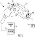
- FIG. 1is a partially simplified view of a charging station and connector therefor, shown as employed with an EV, in accordance with a non-limiting embodiment of the disclosed concept;
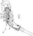
- FIG. 2is a front isometric view of the connector of FIG. 1 , shown with a housing member removed in order to see hidden structures;
- FIG. 3is a front isometric view of the connector of FIG. 2 , shown with portions removed in order to see hidden structures;
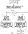
- FIG. 4is a schematic flow diagram, in block form, of a method of charging the EV.
- numbershall mean one or an integer greater than one (i.e., a plurality).
- charging stateshall mean a state in which electric power is being transferred from one source into another.
- a charging state in which a charging station is mechanically coupled and electrically connected to an EVis a state in which electric power is being transferred from the charging station into the EV.
- error stateshall mean a state in which electric power is not being transferred from one source to another, and in which there is a problem with the connection between the two sources.
- an error state in which a charging station is attempting to charge an EVis a state in which there is a problem with the connection between the charging station and the EV, and as a result electric power is not being transferred from the charging station into the EV.
- the term “power ready state”shall mean a state in which electric power is ready to be transferred from one source into another, but is not being transferred because the two sources are not mechanically coupled and are not electrically connected.
- a power ready state of a connector that is not mechanically coupled or electrically connected to an EVis a state in which the connector is ready to transfer electric power, but is not able to because of the lack of connection with the EV.
- FIG. 1shows a partially simplified view of a charging station 2 with an EV 200 , in accordance with a non-limiting embodiment of the disclosed concept.
- the example charging station 2includes a charging box 4 and a connector 100 coupled to the charging box 4 .
- the connector 100advantageously provides a visual indication to an operator (e.g., a driver of the EV 200 ) of charging status. That is, in addition to any indicators provided on the charging box 4 or the EV 200 , the connector 100 provides a separate mechanism for the operator to know charging status.
- the connector 100when connected to the EV 200 , the connector 100 is structured to indicate to the operator whether there is a charging state or whether there is an error state. Additionally, when the connector 100 is not connected to the EV 200 , the connector 100 is also structured to provide a visual indication of whether or not there is a power ready state. In this manner, the operator can save time by more easily determining whether or not the EV 200 is being charged, or will be able to be charged, distinct from prior art charging stations (not shown) in which visual indication of charging status is only provided on the charging box and the EV.
- the charging box 4has a signaling mechanism 6 , and the connector 100 has an electrical receptacle 102 that is electrically connected to the signaling mechanism 6 .
- the EV 200has a pilot signal that has a voltage which allows charging status to be determined, as will be discussed below. In operation, when the operator mechanically couples and electrically connects the receptacle 102 to the EV 200 , and activates the charging box 4 , the EV 200 is able to be charged.
- the connector 100further includes a housing 110 having first and second housing members 111 , 112 that are each coupled to the electrical receptacle 102 and to each other. Additionally, as shown in FIG. 2 , the connector 100 includes an indicating assembly 120 coupled to the second housing member 112 , and an interface (e.g., without limitation, electrical wire 160 ).
- the wire 160electrically connects the indicating assembly 120 to the signaling mechanism 6 ( FIG. 1 ) so that the signaling mechanism 6 can communicate with the indicating assembly 120 and cause the indicating assembly 120 to provide the visual indication of charging status.
- an interface(not shown) to wirelessly communicate a signal from the signaling mechanism 6 to the indicating assembly 120 .
- the interface(e.g., the electrical wire 160 or a wireless communication (not shown)) between the indicating assembly 120 and the signaling mechanism 6 energizes the indicating assembly 120 to provide the visual indication of charging status.
- the indicating assembly 120provides a visual indication corresponding to a charging state, an error state, or a power ready state.
- a visual indication of any suitable number and/or combination of charging statescould be provided on a suitable alternative connector (not shown), without departing from the scope of the disclosed concept.
- a connectornot shown to only have a visual indication for a charging state, and not have visual indications for error and power ready states.
- the indicating assembly 120includes a number of light sources 122 , 124 , 126 and a printed circuit board 128 mechanically coupled and electrically connected to the light sources 122 , 124 , 126 .
- the light sources 122 , 124 , 126 and the printed circuit board 128are electrically connected to the wire 160 in order to allow the signaling mechanism 6 to energize the light sources 122 , 124 , 126 .
- the signaling mechanism 6sends a signal through the wire 160 to the printed circuit board 128 , which in turn communicates with and energizes an appropriate one of the light sources 122 , 124 , 126 .
- the voltage of the pilot signal of the EV 200is communicated by way of the signaling mechanism 6 and the wire 160 to the printed circuit board 128 , thereby allowing charging status to be determined.
- the light sources 122 , 124 , 126correspond to a charging state, an error state, and a power ready state, respectively, and are each structured to be energized independently of each other. Accordingly, when there is a charging state, the light source 122 illuminates and the light sources 124 , 126 remain un-illuminated.
- one of the light sources 124 , 126is illuminated and the other two respective light sources (i.e., two of the light sources 122 , 124 , 126 ) remain un-illuminated.
- the operatorwill readily be able to determine charging status by viewing the connector 100 and observing which one of the three light sources 122 , 124 , 126 is illuminated.
- a connector(not shown) to have an alternative indicating assembly (not shown) such as, for example and without limitation, a display screen to provide a visual indication of charging status, without departing from the scope of the disclosed concept.
- the first housing member 111has a plurality of slots 113 , 114 , 115 that are each aligned with one of the light sources 122 , 124 , 126 .
- the light sources 122 , 124 , 126When one of the light sources 122 , 124 , 126 is energized, visible light passes from an interior of the connector 100 to an exterior of the connector 100 through a respective one of the slots 113 , 114 , 115 in order to provide the appropriate visual indication of charging status.
- each of the light sources 122 , 124 , 126includes a corresponding light emitting diode 130 , 132 , 134 and a corresponding light pipe 136 , 138 , 140 coupled to the light emitting diode 130 , 132 , 134 .
- the light emitting diodes 130 , 132 , 134are electrically connected to the printed circuit board 128 and receive activation signals from the signaling mechanism 6 ( FIG. 1 ) via the printed circuit board 128 and the wire 160 , or via a wireless communication.
- a respective one of the light pipes 136 , 138 , 140transports the visible light from the respective light emitting diode 130 , 132 , 134 through a respective one of the slots 113 , 114 , 115 in order to provide the appropriate visual indication to the operator.
- each of the light sources 122 , 124 , 126operates independently (i.e., only one of the light sources 122 , 124 , 126 is illuminated at a given time) of the other light sources 122 , 124 , 126 , the operator will readily be able to determine charging status. That is, when the operator looks at the connector 100 and sees that one of the light sources 122 , 124 , 126 is illuminated, the operator will be able to know the appropriate charging state based on which of the light sources 122 , 124 , 126 is illuminated.
- the connector 100may also have written labels (i.e., labels of “charging state,” “error state,” and “power ready state”) near the slots 113 , 114 , 115 so that when one of the light sources 122 , 124 , 126 is illuminated, the operator can read the written label below the illuminated light source 122 , 124 , 126 and determine the charging status.
- written labelsi.e., labels of “charging state,” “error state,” and “power ready state”
- the second housing member 112has a pair of opposing internal support portions 116 , 117 that each have a groove.
- the printed circuit board 128( FIG. 2 ) extends into the grooves of the support portions 116 , 117 in order to be reliably supported within the housing 110 (shown in FIG. 1 and partially shown in FIGS. 2 and 3 in the form of the second housing member 112 ).
- the relatively thin printed circuit board 128extends into the grooves of the support portions 116 , 117 and is prevented from moving up and down in the housing 110 (with respect to the orientation of FIG. 3 ).
- the indicating assembly 120is prevented from moving side-to-side (i.e., into and out of the page with respect to the orientation of FIG. 3 ) and is thus fixed with respect to the housing 110 .
- suitable methods of retaining the printed circuit board 128 within the connector 100may be employed, without departing from the scope of the disclosed concept.
- FIG. 4shows a schematic flow diagram, in block form, of a method of charging the EV 200 with the charging station 2 .
- the methodfirst includes the step 300 of illuminating the light source 126 before connecting the connector 100 to the EV 200 .
- thiswill allow the operator attempting to charge the EV 200 to know before connecting the connector 100 to the EV 200 whether or not the charging station 2 is in a condition to charge.
- the operatorwill know that there is a problem with the charging station 2 that would prevent the EV 200 from being charged if connected to the connector 100 , saving the operator significant time by not having to wait until a later time and realize that the EV 200 is not charging.
- an alternative methodto not include the step 300 , as alternative connectors (not shown) may not have the light source 126 .
- the methodfurther includes the step 310 of mechanically coupling and electrically connecting the electrical receptacle 102 to the EV 200 .
- the next step 320is determining whether there is a charging state such that the EV 200 is being charged. This determination is based on the voltage reading of the pilot signal of the EV 200 , in which different voltages correspond to different charging states.
- the methodfurther includes the step 330 of sending a signal from the signaling mechanism 6 to the indicating assembly 120 , and the step 340 of energizing the indicating assembly 120 by illuminating the light source 122 corresponding to the charging state in order to provide a visual indication of charging status.
- the methodfurther includes the step 350 of sending a signal from the signaling mechanism 6 to the indicating assembly 120 , and the step 360 of energizing the indicating assembly 120 by illuminating the light source 124 corresponding to the error state in order to provide a visual indication of charging status.
- the methodfurther includes the step 370 of checking the connections between the connector 100 and the EV 200 , followed by the step 320 of determining whether there is a charging state such that the EV 200 is being charged.
- the operatorobserves that the light source 124 is illuminated, the operator will be able to save time by adjusting the connections, rather than leaving the connector 100 connected to the EV 200 and discovering at a later point in time that the EV 200 was in fact not being charged.
- the methodincludes illuminating no more than one of the light sources 122 , 124 , 126 responsive to the signal from the signaling mechanism 6 .
- the interface between the signaling mechanism 6 and the indicating assembly 120may be wireless.
- the methodmay further include wirelessly communicating the signal from the signaling mechanism 6 to the indicating assembly 120 .
- the disclosed conceptprovides for an improved charging station 2 and connector 100 therefor, and method of charging an EV 200 with the charging station 2 , in which the connector 100 has an indicating assembly 120 that provides visual indication of charging status to an operator, advantageously allowing the operator to have another source (i.e., the connector 100 ) to readily determine charging status, in addition to the charging box 4 and the EV 200 .
Landscapes
- Engineering & Computer Science (AREA)
- Power Engineering (AREA)
- Transportation (AREA)
- Mechanical Engineering (AREA)
- Microelectronics & Electronic Packaging (AREA)
- Physics & Mathematics (AREA)
- Optics & Photonics (AREA)
- Charge And Discharge Circuits For Batteries Or The Like (AREA)
- Electric Propulsion And Braking For Vehicles (AREA)
Abstract
Description
Claims (14)
Priority Applications (1)
| Application Number | Priority Date | Filing Date | Title |
|---|---|---|---|
| US16/843,125US11167655B2 (en) | 2016-01-07 | 2020-04-08 | Charging station and connector therefor, and method of charging an electric vehicle with a charging station |
Applications Claiming Priority (2)
| Application Number | Priority Date | Filing Date | Title |
|---|---|---|---|
| US14/989,980US10647207B2 (en) | 2016-01-07 | 2016-01-07 | Charging station and connector therefor, and method of charging an electric vehicle with a charging station |
| US16/843,125US11167655B2 (en) | 2016-01-07 | 2020-04-08 | Charging station and connector therefor, and method of charging an electric vehicle with a charging station |
Related Parent Applications (1)
| Application Number | Title | Priority Date | Filing Date |
|---|---|---|---|
| US14/989,980ContinuationUS10647207B2 (en) | 2016-01-07 | 2016-01-07 | Charging station and connector therefor, and method of charging an electric vehicle with a charging station |
Publications (2)
| Publication Number | Publication Date |
|---|---|
| US20200231052A1 US20200231052A1 (en) | 2020-07-23 |
| US11167655B2true US11167655B2 (en) | 2021-11-09 |
Family
ID=59270759
Family Applications (2)
| Application Number | Title | Priority Date | Filing Date |
|---|---|---|---|
| US14/989,980Active2037-03-31US10647207B2 (en) | 2016-01-07 | 2016-01-07 | Charging station and connector therefor, and method of charging an electric vehicle with a charging station |
| US16/843,125ActiveUS11167655B2 (en) | 2016-01-07 | 2020-04-08 | Charging station and connector therefor, and method of charging an electric vehicle with a charging station |
Family Applications Before (1)
| Application Number | Title | Priority Date | Filing Date |
|---|---|---|---|
| US14/989,980Active2037-03-31US10647207B2 (en) | 2016-01-07 | 2016-01-07 | Charging station and connector therefor, and method of charging an electric vehicle with a charging station |
Country Status (3)
| Country | Link |
|---|---|
| US (2) | US10647207B2 (en) |
| CA (1) | CA2951937C (en) |
| MX (1) | MX2017000278A (en) |
Cited By (2)
| Publication number | Priority date | Publication date | Assignee | Title |
|---|---|---|---|---|
| LU500992B1 (en) | 2021-12-12 | 2023-06-12 | Eclever Entw Ohg | PROCEDURE FOR TESTING CHARGING POSTS AND THEIR FUNCTIONALITY |
| DE102021214171A1 (en) | 2021-12-12 | 2023-06-15 | eClever Entwicklungs OHG | PROCEDURE FOR TESTING CHARGING POSTS AND THEIR FUNCTIONALITY |
Families Citing this family (16)
| Publication number | Priority date | Publication date | Assignee | Title |
|---|---|---|---|---|
| DE102016112937B4 (en)* | 2016-07-14 | 2025-02-27 | Phoenix Contact E-Mobility Gmbh | connector part with a locking element |
| USD902866S1 (en)* | 2018-08-01 | 2020-11-24 | Phoenix Contact E-Mobility Gmbh | Cable feed-through for electric vehicles |
| US10513197B1 (en)* | 2018-09-17 | 2019-12-24 | Ford Global Technologies, Llc | Vehicle electrical port indicia |
| US20230063349A1 (en)* | 2021-08-24 | 2023-03-02 | Midtronics, Inc. | Power adapter for automotive vehicle maintenance device |
| DE102021131133B4 (en) | 2021-11-26 | 2024-10-24 | Dr. Ing. H.C. F. Porsche Aktiengesellschaft | vehicle with loading trough |
| TWD226205S (en)* | 2022-01-17 | 2023-07-01 | 大陸商比亞迪股份有限公司 | Charger |
| GB2630695B (en)* | 2022-02-07 | 2025-06-25 | Albright Product Design Ltd | An electric vehicle charging plug |
| USD1018469S1 (en)* | 2022-05-17 | 2024-03-19 | Christopher Eckhard Maiwald | Charging adapter |
| WO2024023995A1 (en)* | 2022-07-27 | 2024-02-01 | 日産自動車株式会社 | Error information display method and error information display device |
| USD1034471S1 (en)* | 2022-12-07 | 2024-07-09 | Dropcases Ltd. | Convertor assembly |
| USD1040110S1 (en)* | 2023-06-01 | 2024-08-27 | Shenzhen Yongchuangcheng Technology Co., Ltd. | Charging connector |
| USD1044736S1 (en)* | 2023-07-21 | 2024-10-01 | Weihuang Mai | Charging gun |
| USD1079618S1 (en)* | 2023-07-28 | 2025-06-17 | Guangdong Chongwei technology Co., LTD | Charging gun |
| USD1040089S1 (en)* | 2023-09-12 | 2024-08-27 | Shenzhen Yongchuangcheng Technology Co., Ltd. | Charging connector |
| USD1046773S1 (en)* | 2023-09-12 | 2024-10-15 | Shenzhen Yongchuangcheng Technology Co., Ltd. | Charging adapter |
| DE102024100611A1 (en) | 2024-01-10 | 2025-07-10 | Dr. Ing. H.C. F. Porsche Aktiengesellschaft | Method for increasing safety during a charging process of a battery of an electrically powered motor vehicle |
Citations (13)
| Publication number | Priority date | Publication date | Assignee | Title |
|---|---|---|---|---|
| US6081205A (en)* | 1992-05-19 | 2000-06-27 | Williams; Douglas J. | Electronic parking meter and electric automobile recharging station |
| US6225776B1 (en) | 2000-08-03 | 2001-05-01 | Wellmon Chai | Charging station for electric-powered vehicles |
| US20110051471A1 (en)* | 2009-08-26 | 2011-03-03 | Long Chen | Compact inverter plug for led light strings |
| US20110144823A1 (en) | 2009-07-28 | 2011-06-16 | Michael Muller | Sequential Charging of Multiple Electric Vehicles |
| US20110172839A1 (en) | 2010-01-11 | 2011-07-14 | Leviton Manufacturing Co., Inc. | Electric vehicle supply equipment with timer |
| US20120126747A1 (en)* | 2010-11-19 | 2012-05-24 | Delphi Technologies, Inc. | Battery charger having non-contact electrical switch |
| US20120164850A1 (en) | 2010-12-17 | 2012-06-28 | Ngk Spark Plug Co., Ltd. | Sensor apparatus |
| US20130169226A1 (en) | 2011-12-30 | 2013-07-04 | Electric Transportation Engineering Corporation d/b/a ECOtality North America | Electricity transfer system for modifying an electric vehicle charging station and method of providing, using, and supporting the same |
| US20130201641A1 (en) | 2010-04-09 | 2013-08-08 | David Paul Soden | Portable charging cable with in-line controller |
| US20140015482A1 (en)* | 2012-07-16 | 2014-01-16 | Jason-David Nitzberg | Remote annunciator for electric vehicle supply equipment |
| US8768563B2 (en) | 2012-01-24 | 2014-07-01 | Eaton Corporation | Electric vehicle supply equipment testing apparatus |
| US20150015202A1 (en)* | 2013-07-10 | 2015-01-15 | Lsis Co., Ltd. | Charger for electric vehicle |
| US9071074B2 (en) | 2012-02-20 | 2015-06-30 | Eaton Corporation | Multi-standard, alternating current or direct current compatible electric vehicle supply equipment |
- 2016
- 2016-01-07USUS14/989,980patent/US10647207B2/enactiveActive
- 2016-12-16CACA2951937Apatent/CA2951937C/enactiveActive
- 2017
- 2017-01-05MXMX2017000278Apatent/MX2017000278A/enunknown
- 2020
- 2020-04-08USUS16/843,125patent/US11167655B2/enactiveActive
Patent Citations (13)
| Publication number | Priority date | Publication date | Assignee | Title |
|---|---|---|---|---|
| US6081205A (en)* | 1992-05-19 | 2000-06-27 | Williams; Douglas J. | Electronic parking meter and electric automobile recharging station |
| US6225776B1 (en) | 2000-08-03 | 2001-05-01 | Wellmon Chai | Charging station for electric-powered vehicles |
| US20110144823A1 (en) | 2009-07-28 | 2011-06-16 | Michael Muller | Sequential Charging of Multiple Electric Vehicles |
| US20110051471A1 (en)* | 2009-08-26 | 2011-03-03 | Long Chen | Compact inverter plug for led light strings |
| US20110172839A1 (en) | 2010-01-11 | 2011-07-14 | Leviton Manufacturing Co., Inc. | Electric vehicle supply equipment with timer |
| US20130201641A1 (en) | 2010-04-09 | 2013-08-08 | David Paul Soden | Portable charging cable with in-line controller |
| US20120126747A1 (en)* | 2010-11-19 | 2012-05-24 | Delphi Technologies, Inc. | Battery charger having non-contact electrical switch |
| US20120164850A1 (en) | 2010-12-17 | 2012-06-28 | Ngk Spark Plug Co., Ltd. | Sensor apparatus |
| US20130169226A1 (en) | 2011-12-30 | 2013-07-04 | Electric Transportation Engineering Corporation d/b/a ECOtality North America | Electricity transfer system for modifying an electric vehicle charging station and method of providing, using, and supporting the same |
| US8768563B2 (en) | 2012-01-24 | 2014-07-01 | Eaton Corporation | Electric vehicle supply equipment testing apparatus |
| US9071074B2 (en) | 2012-02-20 | 2015-06-30 | Eaton Corporation | Multi-standard, alternating current or direct current compatible electric vehicle supply equipment |
| US20140015482A1 (en)* | 2012-07-16 | 2014-01-16 | Jason-David Nitzberg | Remote annunciator for electric vehicle supply equipment |
| US20150015202A1 (en)* | 2013-07-10 | 2015-01-15 | Lsis Co., Ltd. | Charger for electric vehicle |
Cited By (3)
| Publication number | Priority date | Publication date | Assignee | Title |
|---|---|---|---|---|
| LU500992B1 (en) | 2021-12-12 | 2023-06-12 | Eclever Entw Ohg | PROCEDURE FOR TESTING CHARGING POSTS AND THEIR FUNCTIONALITY |
| DE102021214171A1 (en) | 2021-12-12 | 2023-06-15 | eClever Entwicklungs OHG | PROCEDURE FOR TESTING CHARGING POSTS AND THEIR FUNCTIONALITY |
| WO2023105093A1 (en) | 2021-12-12 | 2023-06-15 | eClever Entwicklungs OHG | Method for checking charging columns and their range of functions |
Also Published As
| Publication number | Publication date |
|---|---|
| US20170197514A1 (en) | 2017-07-13 |
| CA2951937A1 (en) | 2017-07-07 |
| CA2951937C (en) | 2023-09-12 |
| US20200231052A1 (en) | 2020-07-23 |
| US10647207B2 (en) | 2020-05-12 |
| MX2017000278A (en) | 2018-07-04 |
Similar Documents
| Publication | Publication Date | Title |
|---|---|---|
| US11167655B2 (en) | Charging station and connector therefor, and method of charging an electric vehicle with a charging station | |
| CN105048227B (en) | High voltage connector component | |
| EP2872355B1 (en) | Remote annunciator for electric vehicle supply equipment | |
| CN102891510B (en) | Indicate state, light guide assemblies and the method at electric vehicle charging station | |
| US10106071B2 (en) | Automotive exterior lamp assembly with charge port | |
| KR101587356B1 (en) | Recharging device and recharging method for vehicle | |
| JP2013051753A (en) | Power-supplying connector for supplying power from vehicle to external power-supplied apparatus, method for identifying the connector, system for identifying the connector, power-supplying system using the connector, and vehicle capable of supplying power in the system | |
| JP2023544917A (en) | Charging port plugs for electric vehicles and measures to prevent vehicles from running out of control | |
| EP2783450A1 (en) | Power supply control device | |
| CN205985427U (en) | Electronic equipment | |
| US20050037632A1 (en) | Lighted trailer wiring adapter | |
| EP2674320A2 (en) | A charger for electric vehicle | |
| US20180170199A1 (en) | Isolated high precision pilot voltage generating circuit and electric vehicle supply equipment including the same | |
| US20060235586A1 (en) | Diagnostic device | |
| US10801847B2 (en) | Method and apparatus to provide electrical outlet information for electrified vehicles | |
| CN208621338U (en) | EMU electrically weighs joint-trial experiment device | |
| CN111355106A (en) | Electric discharge device of electric automobile | |
| JP2013090422A (en) | Charging system, power supply side connecting member, and vehicle side connecting member | |
| CN107121621A (en) | It is a kind of to be applied to the cable sorter without communication signal region | |
| US8669737B2 (en) | Courtesy light for an electrical charging system | |
| US8378690B1 (en) | Test cable device for detecting an electrical fault | |
| CN103085674B (en) | Vehicle and electrical-power-feed connector thereof | |
| CN210296680U (en) | Charging and discharging gun | |
| US10604015B1 (en) | Indicating driving battery charger related information inside an electric vehicle to a user of the electric vehicle | |
| CN115009055A (en) | Adapter for connection, interface device, vehicle and connection system |
Legal Events
| Date | Code | Title | Description |
|---|---|---|---|
| AS | Assignment | Owner name:EATON INTELLIGENT POWER LIMITED, IRELAND Free format text:ASSIGNMENT OF ASSIGNORS INTEREST;ASSIGNOR:EATON CORPORATION;REEL/FRAME:052346/0007 Effective date:20171231 | |
| FEPP | Fee payment procedure | Free format text:ENTITY STATUS SET TO UNDISCOUNTED (ORIGINAL EVENT CODE: BIG.); ENTITY STATUS OF PATENT OWNER: LARGE ENTITY | |
| STPP | Information on status: patent application and granting procedure in general | Free format text:NON FINAL ACTION MAILED | |
| STPP | Information on status: patent application and granting procedure in general | Free format text:RESPONSE TO NON-FINAL OFFICE ACTION ENTERED AND FORWARDED TO EXAMINER | |
| STPP | Information on status: patent application and granting procedure in general | Free format text:FINAL REJECTION MAILED | |
| STPP | Information on status: patent application and granting procedure in general | Free format text:RESPONSE AFTER FINAL ACTION FORWARDED TO EXAMINER | |
| STPP | Information on status: patent application and granting procedure in general | Free format text:ADVISORY ACTION MAILED | |
| STPP | Information on status: patent application and granting procedure in general | Free format text:DOCKETED NEW CASE - READY FOR EXAMINATION | |
| STPP | Information on status: patent application and granting procedure in general | Free format text:NOTICE OF ALLOWANCE MAILED -- APPLICATION RECEIVED IN OFFICE OF PUBLICATIONS | |
| STPP | Information on status: patent application and granting procedure in general | Free format text:PUBLICATIONS -- ISSUE FEE PAYMENT VERIFIED | |
| STCF | Information on status: patent grant | Free format text:PATENTED CASE | |
| MAFP | Maintenance fee payment | Free format text:PAYMENT OF MAINTENANCE FEE, 4TH YEAR, LARGE ENTITY (ORIGINAL EVENT CODE: M1551); ENTITY STATUS OF PATENT OWNER: LARGE ENTITY Year of fee payment:4 |