US11167507B2 - Method for manufacturing a wind turbine rotor blade root assembly - Google Patents
Method for manufacturing a wind turbine rotor blade root assemblyDownload PDFInfo
- Publication number
- US11167507B2 US11167507B2US15/923,043US201815923043AUS11167507B2US 11167507 B2US11167507 B2US 11167507B2US 201815923043 AUS201815923043 AUS 201815923043AUS 11167507 B2US11167507 B2US 11167507B2
- Authority
- US
- United States
- Prior art keywords
- root
- holes
- plate
- fluid hole
- inserts
- Prior art date
- Legal status (The legal status is an assumption and is not a legal conclusion. Google has not performed a legal analysis and makes no representation as to the accuracy of the status listed.)
- Active, expires
Links
Images


Classifications
- B—PERFORMING OPERATIONS; TRANSPORTING
- B29—WORKING OF PLASTICS; WORKING OF SUBSTANCES IN A PLASTIC STATE IN GENERAL
- B29C—SHAPING OR JOINING OF PLASTICS; SHAPING OF MATERIAL IN A PLASTIC STATE, NOT OTHERWISE PROVIDED FOR; AFTER-TREATMENT OF THE SHAPED PRODUCTS, e.g. REPAIRING
- B29C70/00—Shaping composites, i.e. plastics material comprising reinforcements, fillers or preformed parts, e.g. inserts
- B29C70/04—Shaping composites, i.e. plastics material comprising reinforcements, fillers or preformed parts, e.g. inserts comprising reinforcements only, e.g. self-reinforcing plastics
- B29C70/28—Shaping operations therefor
- B29C70/40—Shaping or impregnating by compression not applied
- B29C70/42—Shaping or impregnating by compression not applied for producing articles of definite length, i.e. discrete articles
- B29C70/46—Shaping or impregnating by compression not applied for producing articles of definite length, i.e. discrete articles using matched moulds, e.g. for deforming sheet moulding compounds [SMC] or prepregs
- B29C70/48—Shaping or impregnating by compression not applied for producing articles of definite length, i.e. discrete articles using matched moulds, e.g. for deforming sheet moulding compounds [SMC] or prepregs and impregnating the reinforcements in the closed mould, e.g. resin transfer moulding [RTM], e.g. by vacuum
- B—PERFORMING OPERATIONS; TRANSPORTING
- B29—WORKING OF PLASTICS; WORKING OF SUBSTANCES IN A PLASTIC STATE IN GENERAL
- B29D—PRODUCING PARTICULAR ARTICLES FROM PLASTICS OR FROM SUBSTANCES IN A PLASTIC STATE
- B29D99/00—Subject matter not provided for in other groups of this subclass
- B29D99/0025—Producing blades or the like, e.g. blades for turbines, propellers, or wings
- B29D99/0028—Producing blades or the like, e.g. blades for turbines, propellers, or wings hollow blades
- B—PERFORMING OPERATIONS; TRANSPORTING
- B29—WORKING OF PLASTICS; WORKING OF SUBSTANCES IN A PLASTIC STATE IN GENERAL
- B29C—SHAPING OR JOINING OF PLASTICS; SHAPING OF MATERIAL IN A PLASTIC STATE, NOT OTHERWISE PROVIDED FOR; AFTER-TREATMENT OF THE SHAPED PRODUCTS, e.g. REPAIRING
- B29C70/00—Shaping composites, i.e. plastics material comprising reinforcements, fillers or preformed parts, e.g. inserts
- B29C70/04—Shaping composites, i.e. plastics material comprising reinforcements, fillers or preformed parts, e.g. inserts comprising reinforcements only, e.g. self-reinforcing plastics
- B29C70/28—Shaping operations therefor
- B29C70/40—Shaping or impregnating by compression not applied
- B29C70/42—Shaping or impregnating by compression not applied for producing articles of definite length, i.e. discrete articles
- B29C70/44—Shaping or impregnating by compression not applied for producing articles of definite length, i.e. discrete articles using isostatic pressure, e.g. pressure difference-moulding, vacuum bag-moulding, autoclave-moulding or expanding rubber-moulding
- B29C70/443—Shaping or impregnating by compression not applied for producing articles of definite length, i.e. discrete articles using isostatic pressure, e.g. pressure difference-moulding, vacuum bag-moulding, autoclave-moulding or expanding rubber-moulding and impregnating by vacuum or injection
- B—PERFORMING OPERATIONS; TRANSPORTING
- B29—WORKING OF PLASTICS; WORKING OF SUBSTANCES IN A PLASTIC STATE IN GENERAL
- B29C—SHAPING OR JOINING OF PLASTICS; SHAPING OF MATERIAL IN A PLASTIC STATE, NOT OTHERWISE PROVIDED FOR; AFTER-TREATMENT OF THE SHAPED PRODUCTS, e.g. REPAIRING
- B29C70/00—Shaping composites, i.e. plastics material comprising reinforcements, fillers or preformed parts, e.g. inserts
- B29C70/04—Shaping composites, i.e. plastics material comprising reinforcements, fillers or preformed parts, e.g. inserts comprising reinforcements only, e.g. self-reinforcing plastics
- B29C70/28—Shaping operations therefor
- B29C70/54—Component parts, details or accessories; Auxiliary operations, e.g. feeding or storage of prepregs or SMC after impregnation or during ageing
- B29C70/546—Measures for feeding or distributing the matrix material in the reinforcing structure
- B29C70/547—Measures for feeding or distributing the matrix material in the reinforcing structure using channels or porous distribution layers incorporated in or associated with the product
- B—PERFORMING OPERATIONS; TRANSPORTING
- B29—WORKING OF PLASTICS; WORKING OF SUBSTANCES IN A PLASTIC STATE IN GENERAL
- B29C—SHAPING OR JOINING OF PLASTICS; SHAPING OF MATERIAL IN A PLASTIC STATE, NOT OTHERWISE PROVIDED FOR; AFTER-TREATMENT OF THE SHAPED PRODUCTS, e.g. REPAIRING
- B29C70/00—Shaping composites, i.e. plastics material comprising reinforcements, fillers or preformed parts, e.g. inserts
- B29C70/68—Shaping composites, i.e. plastics material comprising reinforcements, fillers or preformed parts, e.g. inserts by incorporating or moulding on preformed parts, e.g. inserts or layers, e.g. foam blocks
- B29C70/74—Moulding material on a relatively small portion of the preformed part, e.g. outsert moulding
- B29C70/76—Moulding on edges or extremities of the preformed part
- B—PERFORMING OPERATIONS; TRANSPORTING
- B29—WORKING OF PLASTICS; WORKING OF SUBSTANCES IN A PLASTIC STATE IN GENERAL
- B29C—SHAPING OR JOINING OF PLASTICS; SHAPING OF MATERIAL IN A PLASTIC STATE, NOT OTHERWISE PROVIDED FOR; AFTER-TREATMENT OF THE SHAPED PRODUCTS, e.g. REPAIRING
- B29C70/00—Shaping composites, i.e. plastics material comprising reinforcements, fillers or preformed parts, e.g. inserts
- B29C70/68—Shaping composites, i.e. plastics material comprising reinforcements, fillers or preformed parts, e.g. inserts by incorporating or moulding on preformed parts, e.g. inserts or layers, e.g. foam blocks
- B29C70/86—Incorporated in coherent impregnated reinforcing layers, e.g. by winding
- F—MECHANICAL ENGINEERING; LIGHTING; HEATING; WEAPONS; BLASTING
- F03—MACHINES OR ENGINES FOR LIQUIDS; WIND, SPRING, OR WEIGHT MOTORS; PRODUCING MECHANICAL POWER OR A REACTIVE PROPULSIVE THRUST, NOT OTHERWISE PROVIDED FOR
- F03D—WIND MOTORS
- F03D1/00—Wind motors with rotation axis substantially parallel to the air flow entering the rotor
- F03D1/06—Rotors
- F03D1/065—Rotors characterised by their construction elements
- F03D1/0675—Rotors characterised by their construction elements of the blades
- B—PERFORMING OPERATIONS; TRANSPORTING
- B29—WORKING OF PLASTICS; WORKING OF SUBSTANCES IN A PLASTIC STATE IN GENERAL
- B29L—INDEXING SCHEME ASSOCIATED WITH SUBCLASS B29C, RELATING TO PARTICULAR ARTICLES
- B29L2031/00—Other particular articles
- B29L2031/08—Blades for rotors, stators, fans, turbines or the like, e.g. screw propellers
- B29L2031/082—Blades, e.g. for helicopters
- B29L2031/085—Wind turbine blades
- F—MECHANICAL ENGINEERING; LIGHTING; HEATING; WEAPONS; BLASTING
- F01—MACHINES OR ENGINES IN GENERAL; ENGINE PLANTS IN GENERAL; STEAM ENGINES
- F01D—NON-POSITIVE DISPLACEMENT MACHINES OR ENGINES, e.g. STEAM TURBINES
- F01D5/00—Blades; Blade-carrying members; Heating, heat-insulating, cooling or antivibration means on the blades or the members
- F01D5/12—Blades
- F01D5/14—Form or construction
- F01D5/18—Hollow blades, i.e. blades with cooling or heating channels or cavities; Heating, heat-insulating or cooling means on blades
- F—MECHANICAL ENGINEERING; LIGHTING; HEATING; WEAPONS; BLASTING
- F03—MACHINES OR ENGINES FOR LIQUIDS; WIND, SPRING, OR WEIGHT MOTORS; PRODUCING MECHANICAL POWER OR A REACTIVE PROPULSIVE THRUST, NOT OTHERWISE PROVIDED FOR
- F03D—WIND MOTORS
- F03D1/00—Wind motors with rotation axis substantially parallel to the air flow entering the rotor
- F03D1/06—Rotors
- F03D1/065—Rotors characterised by their construction elements
- F03D1/0658—Arrangements for fixing wind-engaging parts to a hub
- F—MECHANICAL ENGINEERING; LIGHTING; HEATING; WEAPONS; BLASTING
- F05—INDEXING SCHEMES RELATING TO ENGINES OR PUMPS IN VARIOUS SUBCLASSES OF CLASSES F01-F04
- F05B—INDEXING SCHEME RELATING TO WIND, SPRING, WEIGHT, INERTIA OR LIKE MOTORS, TO MACHINES OR ENGINES FOR LIQUIDS COVERED BY SUBCLASSES F03B, F03D AND F03G
- F05B2230/00—Manufacture
- F05B2230/20—Manufacture essentially without removing material
- F05B2230/23—Manufacture essentially without removing material by permanently joining parts together
- Y—GENERAL TAGGING OF NEW TECHNOLOGICAL DEVELOPMENTS; GENERAL TAGGING OF CROSS-SECTIONAL TECHNOLOGIES SPANNING OVER SEVERAL SECTIONS OF THE IPC; TECHNICAL SUBJECTS COVERED BY FORMER USPC CROSS-REFERENCE ART COLLECTIONS [XRACs] AND DIGESTS
- Y02—TECHNOLOGIES OR APPLICATIONS FOR MITIGATION OR ADAPTATION AGAINST CLIMATE CHANGE
- Y02E—REDUCTION OF GREENHOUSE GAS [GHG] EMISSIONS, RELATED TO ENERGY GENERATION, TRANSMISSION OR DISTRIBUTION
- Y02E10/00—Energy generation through renewable energy sources
- Y02E10/70—Wind energy
- Y02E10/72—Wind turbines with rotation axis in wind direction
- Y—GENERAL TAGGING OF NEW TECHNOLOGICAL DEVELOPMENTS; GENERAL TAGGING OF CROSS-SECTIONAL TECHNOLOGIES SPANNING OVER SEVERAL SECTIONS OF THE IPC; TECHNICAL SUBJECTS COVERED BY FORMER USPC CROSS-REFERENCE ART COLLECTIONS [XRACs] AND DIGESTS
- Y02—TECHNOLOGIES OR APPLICATIONS FOR MITIGATION OR ADAPTATION AGAINST CLIMATE CHANGE
- Y02P—CLIMATE CHANGE MITIGATION TECHNOLOGIES IN THE PRODUCTION OR PROCESSING OF GOODS
- Y02P70/00—Climate change mitigation technologies in the production process for final industrial or consumer products
- Y02P70/50—Manufacturing or production processes characterised by the final manufactured product
Definitions
- the present subject matterrelates generally to wind turbines and, more particularly, to methods for manufacturing wind turbine rotor blade root assemblies.
- Wind poweris considered one of the cleanest, most environmentally friendly energy sources presently available, and wind turbines have gained increased attention in this regard.
- a modern wind turbinetypically includes a tower, a generator, a gearbox, a nacelle, and a rotor.
- the rotoris coupled to the nacelle and includes a rotatable hub having one or more rotor blades.
- the rotor bladesare connected to the hub by a blade root.
- the rotor bladescapture kinetic energy from wind using known airfoil principles and convert the kinetic energy into mechanical energy through rotational energy to turn a shaft coupling the rotor blades to a gearbox, or if a gearbox is not used, directly to the generator.
- the generatorthen converts the mechanical energy to electrical energy that may be deployed to a utility grid.
- the particular size of the rotor bladesis a significant factor contributing to the overall capacity of the wind turbine. Specifically, increases in the length or span of a rotor blade may generally lead to an overall increase in the energy production of a wind turbine. Accordingly, efforts to increase the size of rotor blades aid in the continuing growth of wind turbine technology and the adoption of wind energy as an alternative and commercially competitive energy source. Such increases in rotor blade size, however, may impose increased loads on various wind turbine components. For example, larger rotor blades may experience increased stresses at the connection between the blade root and the hub, leading to challenging design constraints, both characterized by extreme events and fatigue life requirements.
- Modern methods for manufacturing rotor bladesinclude curing a plurality of root bolts into the blade root during a vacuum infusion process. More specifically, the root bolts can be placed between the inner and outer skin layers of the blade root and cured directly therebetween with a resin material during the infusion process. Thus, such a process eliminates machining of the blade root after the part has cured to accommodate the root bolts.
- a composite infused partoften has limited access to the vacuum from one side of the part, thus limiting the flow of the resin to all areas of the part.
- the lack of vacuum pressure differential to drive the flow of resin to all areas of the partcan lead to under infused areas of the composite, thereby causing detrimental defects within the final part.
- the present disclosureis directed to methods for manufacturing rotor blade roots that provide an additional vacuum path along the mold side of the part to improve infusion results.
- the present disclosureis directed to a method for manufacturing a root assembly of a rotor blade of a wind turbine.
- the methodincludes placing one or more outer skin layers onto a blade mold. Further, the method includes arranging a root plate adjacent to an end face of the blade mold.
- the root plateincludes at least one fluid hole configured therethrough to provide a non-gas tight root plate.
- the root plateincludes a plurality of through holes.
- the methodalso includes placing a plurality of root inserts atop the one or more outer skin layers and abutting against the root plate.
- the plurality of root insertseach define a longitudinal fastener hole. As such, the longitudinal fastener holes of the plurality of root inserts align with the plurality of through holes of the root plate.
- the methodincludes placing one or more inner skin layers atop the plurality of root inserts.
- the methodalso includes inserting a root fastener into each of the aligned through holes and longitudinal fastener holes.
- the methodincludes securing the one or more outer skin layers, the plurality of root inserts, the one or more inner skin layers, and the root fasteners together to form the root assembly via the vacuum infusion process.
- a center point of the at least one fluid holeis offset from a center point of a lower-most through hole of the plurality of through holes.
- the root platemay further include a plurality of additional fluid holes arranged circumferentially therein for allowing at least one of gas or resin material to pass therethrough during infusion.
- the fluid hole(s)may be located on a lower half of the root plate. In additional embodiments, the fluid hole(s) may be located at least partially between two of the plurality of through holes.
- the vacuum infusion processmay include placing a first vacuum bag atop the one or more inner skin layers, removing air between the blade mold and the first vacuum bag, and infusing a resin material into the first vacuum bag.
- the methodmay further include creating an external vacuum with the fluid hole in the root plate by placing the first vacuum bag or the second vacuum bag atop an outlet of the fluid hole, removing air from the first vacuum bag or the second vacuum bag, and infusing a resin material into the first vacuum bag or the second vacuum bag.
- the methodmay include placing a membrane over at least one of an inlet or the outlet of the fluid hole in the root plate.
- the membraneis configured to allow gas to flow therethrough but preventing the resin material from flowing therethrough.
- the methodmay also include sealing off the root fasteners from the resin material during the infusing step.
- the present disclosureis directed to a system for manufacturing a root assembly of a rotor blade of a wind turbine.
- the systemincludes at least one blade mold for receiving one or more outer skins, a plurality of root inserts, one or more inner skin layers, and a plurality of root fasteners.
- the methodincludes a root plate for positioning a plurality of root fasteners circumferentially around the root assembly.
- the root plateincludes a plurality of through holes that align with the longitudinal fastener holes of the plurality of root inserts of the root assembly. The aligned through holes and fastener holes are configured to receive the plurality of root fasteners.
- the systemalso includes at least one seal arranged between the root plate and the blade mold that forms a non-gas tight connection with at least one of the root plate or the blade mold during a vacuum infusion process.
- the systemalso includes a vacuum infusion system for securing the one or more outer skins, the plurality of root inserts, the one or more inner skin layers, and the plurality of root fasteners together via a resin material to form the root assembly.
- the systemmay further include any of the additional features as described herein.
- the sealmay include a fluid opening or may be formed of a breathable material. More specifically, the breathable material as described herein is permeable to vapor but not resin.
- the non-gas tight featuremay include at least one fluid hole configured through the root plate.
- the non-gas tight featuremay include at least one opening configured through a seal arranged between the root plate and the blade mold.
- the systemmay further include any of the additional features as described herein.
- FIG. 1illustrates a perspective view of one embodiment of a wind turbine according to the present disclosure
- FIG. 2illustrates a perspective view of one embodiment of a root assembly of a wind turbine according to the present disclosure
- FIG. 3illustrates an enlarged view of a portion of the root assembly of FIG. 2 according to the present disclosure
- FIG. 4illustrates a cross-sectional view of one embodiment of the root assembly according to the present disclosure
- FIG. 5illustrates a flow diagram of one embodiment of a method for manufacturing a root assembly of a rotor blade of a wind turbine according to the present disclosure
- FIG. 6illustrates a partial cross-sectional view of one embodiment of a system for manufacturing a root assembly according to the present disclosure
- FIG. 7illustrates a front view of one embodiment of a non-gas tight root plate of a system for manufacturing a root assembly according to the present disclosure
- FIG. 8illustrates a partial cross-sectional view of another embodiment of a system for manufacturing a root assembly according to the present disclosure
- FIG. 9illustrates a front view of another embodiment of a non-gas tight root plate of a system for manufacturing a root assembly according to the present disclosure
- FIG. 10illustrates a partial cross-sectional view of still another embodiment of a system for manufacturing a root assembly according to the present disclosure
- FIG. 11illustrates a front view of still another embodiment of a system for manufacturing a root assembly according to the present disclosure, particularly illustrated a non-gas tight connection between a root plate and a mold of the system;
- FIG. 12illustrates a partial cross-sectional view of yet another embodiment of a system for manufacturing a root assembly according to the present disclosure, particularly illustrating the root plate secured to the ground;
- FIG. 13illustrates a partial cross-sectional view of another embodiment of a system for manufacturing a root assembly according to the present disclosure, particularly illustrating the root plate secured to framework that supports the blade mold;
- FIG. 14illustrates a partial cross-sectional view of still another embodiment of a system for manufacturing a root assembly according to the present disclosure, particularly illustrating an L-shaped blade mold;
- FIG. 15illustrates a partial cross-sectional view of a further another embodiment of a system for manufacturing a root assembly according to the present disclosure, particularly illustrating an L-shaped root plate that sits atop the blade mold;
- FIG. 16illustrates a partial cross-sectional view of an additional embodiment of a system for manufacturing a root assembly according to the present disclosure, particularly illustrating an L-shaped root plate that sits atop the blade mold and is secured to the blade mold via a plurality of dowel pins.
- the present disclosureis directed to improved methods for manufacturing wind turbine rotor blades that utilizes a root plate, a plurality of root inserts each defining a fastener hole, and a non-gas tight feature.
- the non-gas tight featuremay be created via an additional vacuum port (also referred to herein as a fluid hole) in the root plate to create a non-gas tight root plate.
- the non-gas tight featuremay be created via a non-gas tight connection of a seal between the root plate and the blade mold, e.g. by providing a hole or opening through the seal.
- the additional vacuum port in the root plate and/or the hole in the sealimproves resin flow by drawing gas and/or resin therethrough, thereby decreasing potential manufacturing defects in the infused part and more effectively drawing the resin below the root inserts.
- non-gas tightgenerally refers to deliberately enabling gas flow to pass through, for example, by providing a hole, leak, or similar in one or more components of the system.
- the pressure drop across the non-gas tight featuree.g. the root plate or seal
- gas-tight systemsmay allow some level of gas to pass through certain components of the system, the overall goal of such systems is to minimize such flow.
- the system of the present disclosurepurposely increases the amount of gas flow allowed to pass through one or more components thereof for the benefit of drawing resin to an area that would otherwise be difficult to reach.
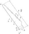
- FIG. 1illustrates a perspective view of one embodiment of a wind turbine 10 according to the present disclosure. More specifically, as shown, the wind turbine 10 includes a tower 12 extending from a support surface 14 , a nacelle 16 mounted on the tower 12 , and a rotor 18 coupled to the nacelle 16 .
- the rotor 18includes a rotatable hub 20 and at least one rotor blade 22 coupled to and extending outwardly from the hub 20 .
- the rotor 18includes three rotor blades 22 .
- the rotor 18may include more or less than three rotor blades 22 .
- Each rotor blade 22may be spaced about the hub 20 to facilitate rotating the rotor 18 to enable kinetic energy to be transferred from the wind into usable mechanical energy, and subsequently, electrical energy.
- the hub 20may be rotatably coupled to the nacelle 16 , which encloses an electric generator (not shown) to permit electrical energy to be produced.
- the rotor blade 22includes a body shell 108 defining a pressure side 110 and a suction side 112 extending between a leading edge 114 and a trailing edge 116 .
- the body shell 108may generally be configured to extend between a blade root 105 and a blade tip 106 disposed opposite the blade root 105 and may serve as the outer casing/covering of inner load bearing structure of the blade 22 .
- the rotor blade 22may have a span 118 defining the total length between the blade root 105 and the blade tip 106 .
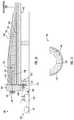
- the blade root section 104includes end face 124 and has a substantially annular cross-section defined by an outer sidewall surface 120 and an inner sidewall surface 122 . More specifically, a plurality of root inserts 126 are provided between the sidewall surfaces 120 , 122 each defining a longitudinal fastener hole 128 extending from the end face 124 to a predetermined span-wise distance within the root assembly 100 . Thus, as shown, a plurality of root fasteners 130 can be provided through the longitudinal fastener holes 128 of the root inserts 126 .
- FIG. 4a cross-sectional view of one embodiment of the root assembly 100 connected to the hub 20 according to the present disclosure is illustrated. More specifically, as shown, the blade root section 104 is connected to a hub 20 with the root fasteners 130 through a pitch bearing 106 . Further, as shown, the blade root section 104 includes inner 122 and outer 120 sidewall surfaces, wherein the root fasteners 130 are circumferentially spaced (equally or otherwise) between the inner 122 and the outer 120 sidewall surfaces. Moreover, as shown, the plurality of root inserts 126 are provided between the sidewall surfaces 120 , 122 and each define one of the longitudinal fastener holes 128 .
- the root inserts 126may include a threaded portion 132 having internal threads for threading the root fasteners 130 thereto. Further, as shown, the root fasteners 130 may be secured within the longitudinal fastener holes 128 via nuts 138 which are configured to provide a predetermined preload to the root fasteners 130 .
- the root assembly 100may include a filler material 134 positioned to fill a gap between the inner 122 and the outer 120 sidewall surfaces adjacent to the root inserts 126 .
- the present disclosureis directed to systems and methods for manufacturing root assemblies for wind turbines, such as the root assembly 100 illustrated in FIGS. 3 and 4 .
- FIG. 5a flow diagram of one embodiment of a method 200 for manufacturing the root assembly 100 according to the present disclosure is illustrated.
- FIGS. 6-11illustrate various embodiments of a system 140 for manufacturing the root assembly 100 according to the present disclosure.
- the method 200includes placing one or more outer skin layers 120 onto a blade mold 142 .
- the outer skin layers 120form the outer sidewall surface 120 of the final root assembly 100 , therefore, reference character 120 is used to describe both terms.
- the method 200includes arranging a root plate 144 adjacent to an end face of the blade mold 142 .
- the root plate 144may have a generally arcuate or curved shape that corresponds to the shape or profile of the end face 124 of the root assembly 100 .
- the root plate 144includes a plurality of through holes 146 configured to align with longitudinal fastener holes 128 of the root inserts 126 to assist in properly locating and holding the root fasteners 130 in place during manufacturing of the root assembly 100 .
- the root plate 144may be a non-gas tight plate that allows gas and/or a resin to pass through, facilitated by a vacuum pump.
- the non-gas tight platemay include any suitable non-gas tight feature, such as a hole, that provides improved resin flow during a vacuum infusion process.
- the non-gas tight featuremay correspond to at least one fluid hole 148 configured through the root plate 144 .
- the root plate 144includes a single fluid hole 148 .
- the root plate 144may include a plurality of fluid holes 148 arranged circumferentially around the root plate 144 for allowing gas and/or resin material to pass therethrough during infusion.
- the fluid hole(s) 148 in the root plate 144may be located on a lower half of the root plate 144 .
- a center point 149 of the fluid hole(s) 148may be offset from a center point 147 of a lower-most through hole of the plurality of through holes 146 , e.g. as shown via offset 150 .
- the center point 149 of the fluid hole(s) 148may be located below the center point 147 of the lower-most through hole 146 .
- the center point 148 of the fluid hole(s) 148may be located above the center point 147 of the lower-most through hole 146 .
- the fluid hole(s) 148may be located at least partially between two of the through holes 146 .
- the method 200includes placing the plurality of root inserts 126 atop the one or more outer skin layers 120 and abutting against the root plate 144 .
- each of the root inserts 126define one of the longitudinal fastener holes 128 .
- the longitudinal fastener holes 128 of the plurality of root inserts 126align with the plurality of through holes 146 of the root plate 144 .
- the method 200further includes inserting a root fastener 130 into each of the aligned through holes 146 and longitudinal fastener holes 128 .
- the method 200further includes placing one or more inner skin layers 122 atop the plurality of root inserts 126 .
- the inner skin layers 122form the inner sidewall surface 122 of the final root assembly 100 , therefore, reference character 122 is used to describe both terms.
- the method 200includes securing the outer skin layer(s) 120 , the root inserts 126 , the inner skin layer(s) 122 , and the root fasteners 130 together to form the root assembly 100 via the vacuum infusion process.
- the vacuum infusion processmay include placing a first vacuum bag 156 atop the one or more inner skin layers 122 , removing air between the blade mold 142 and the first vacuum bag 156 , and infusing a resin material 158 into the first vacuum bag 156 .
- the system 140may include a non-gas tight connection, rather than a non-gas tight root plate 144 .
- the non-gas tight connectionmay be provided via at least one opening 154 configured through a seal 172 arranged between the root plate 144 and the blade mold 142 .
- the system 140may also include an external vacuum system 166 for providing an external vacuum to the non-gas tight feature/connection.
- the external vacuummay be created by placing vacuum bag 164 atop an outlet 168 of the non-gas tight feature/connection, e.g. the seal opening 154 , removing air from the vacuum bag 164 (e.g.
- the external vacuummay be created by placing a second vacuum bag 164 atop the outlet 168 of the fluid hole(s) 148 and/or the opening(s) 154 , removing air from the second vacuum bag 164 (e.g. via the vacuum pump 167 ), infusing the resin material 158 into the second vacuum bag 164 , drawing the resin material 158 through the root assembly 100 towards the fluid hole(s) 148 and/or the opening(s) 154 , and capturing any excess resin material 158 that flows through the fluid hole(s) 148 and/or the opening(s) 154 into the storage container 169 .
- the system 140may also include at least one membrane 162 positioned at the inlet and/or outlet 168 of the fluid hole(s) 148 and/or the opening(s) 154 , i.e. between the vacuum bags 156 , 164 and the outlet 168 .
- the membrane(s) 162is gas permeable (i.e. the membrane 162 allows gas to flow therethrough but prevents the resin material 158 from flowing therethrough).
- the system 140may include one or more additional seals 160 , 165 , 170 , 172 for maintaining system-wide vacuum integrity.
- one or more first seals 165may be provided between the root plate 144 and the first vacuum bag 156 . More specifically, in one embodiment, such seals 165 may correspond to a temporary mold sealant, such as tacky tape.
- the system 140may also include one or more second seals 160 for sealing off the root fasteners 130 from the resin material 158 during the infusing step.
- the second seals(s) 160may correspond to O-seals that fit around the outer diameter of the root fasteners 130 .
- the second seals 160are configured to prevent the resin material 158 from flowing into the longitudinal fastener holes 128 of the root inserts 126 .
- the system 140may include one or more third seals 170 at the outlet 168 of the fluid hole(s) 148 and/or the fluid opening(s) 154 , e.g. between the membrane 162 and the respective vacuum bag 156 , 164 .
- the third seals 170are configured to assist in creating the external vacuum for the fluid hole(s) and/or opening(s) 148 , 154 .
- the system 140may include one or more fourth seals 172 positioned between the root plate 144 and the blade mold 142 .
- the fourth seals 172may correspond to silicone beads, tacky tape, or similar.
- the seals 160 , 165 , 170 , 172 described hereinprovide a sealed system, except for the fluid hole(s) 148 and/or opening(s) 154 that allow gas and/or resin to pass therethrough.
- FIGS. 12-16various cross-sectional views of additional embodiments of the system 140 for manufacturing the root assembly 100 according to the present disclosure are illustrated. More specifically, as shown in FIG. 12 , the root plate 144 is secured to the ground 176 via one or more supports 174 . Thus, as shown, the root plate 144 is not secured to the blade mold 142 . Therefore, in such embodiments, the support(s) 174 are configured to hinge into and out of position to provide pressure to the root plate 144 . Similarly, as shown in FIG. 13 , a partial cross-sectional view of another embodiment of the system 140 for manufacturing the root assembly 100 according to the present disclosure is illustrated. More specifically, as shown, the root plate 144 is secured to framework 178 that supports the blade mold 174 via the support(s) 174 . Thus, like the embodiment of FIG. 12 , the root plate 144 is not secured to the blade mold 142 .
- the root plate 144may be eliminated.
- the blade mold 142may have an L-shape such that the blade mold 142 is configured to operate similar to the root plate 144 described herein.
- the blade mold 142may include at least one fluid hole 148 to provide a non-gas tight feature.
- the root plate 144has an L-shape such that the plate 144 sits atop the blade mold 142 .
- the root assembly 100may include an insert 180 arranged between the blade mold 142 and the root plate 144 .
- the insert 180is configured to position the root plate 144 atop the blade mold 142 .
- the insert 180may be constructed of a metallic material.
- the root plate 144may be secured to the blade mold 142 via one or more dowel pins 182 .
- the illustrated system 140includes at least one fluid hole 148 configured through the L-shaped root plate 44 , the insert 180 , and the blade mold 142 to provide a non-gas tight connection.
Landscapes
- Engineering & Computer Science (AREA)
- Mechanical Engineering (AREA)
- Chemical & Material Sciences (AREA)
- Composite Materials (AREA)
- Life Sciences & Earth Sciences (AREA)
- Sustainable Development (AREA)
- Sustainable Energy (AREA)
- Combustion & Propulsion (AREA)
- General Engineering & Computer Science (AREA)
- Wind Motors (AREA)
- Turbine Rotor Nozzle Sealing (AREA)
Abstract
Description
Claims (14)
Priority Applications (6)
| Application Number | Priority Date | Filing Date | Title |
|---|---|---|---|
| US15/923,043US11167507B2 (en) | 2018-03-16 | 2018-03-16 | Method for manufacturing a wind turbine rotor blade root assembly |
| EP19714043.7AEP3765733A1 (en) | 2018-03-16 | 2019-03-15 | Method for manufacturing a wind turbine rotor blade root assembly |
| CN201980032812.5ACN112154267B (en) | 2018-03-16 | 2019-03-15 | Method for manufacturing a wind turbine rotor blade root assembly |
| PCT/US2019/022465WO2019178476A1 (en) | 2018-03-16 | 2019-03-15 | Method for manufacturing a wind turbine rotor blade root assembly |
| MX2020009571AMX2020009571A (en) | 2018-03-16 | 2019-03-15 | Method for manufacturing a wind turbine rotor blade root assembly. |
| MA052147AMA52147A (en) | 2018-03-16 | 2019-03-15 | METHOD OF MANUFACTURING A WIND TURBINE ROTOR BLADE ROOT ASSEMBLY |
Applications Claiming Priority (1)
| Application Number | Priority Date | Filing Date | Title |
|---|---|---|---|
| US15/923,043US11167507B2 (en) | 2018-03-16 | 2018-03-16 | Method for manufacturing a wind turbine rotor blade root assembly |
Publications (2)
| Publication Number | Publication Date |
|---|---|
| US20190283347A1 US20190283347A1 (en) | 2019-09-19 |
| US11167507B2true US11167507B2 (en) | 2021-11-09 |
Family
ID=65952191
Family Applications (1)
| Application Number | Title | Priority Date | Filing Date |
|---|---|---|---|
| US15/923,043Active2040-02-29US11167507B2 (en) | 2018-03-16 | 2018-03-16 | Method for manufacturing a wind turbine rotor blade root assembly |
Country Status (6)
| Country | Link |
|---|---|
| US (1) | US11167507B2 (en) |
| EP (1) | EP3765733A1 (en) |
| CN (1) | CN112154267B (en) |
| MA (1) | MA52147A (en) |
| MX (1) | MX2020009571A (en) |
| WO (1) | WO2019178476A1 (en) |
Cited By (1)
| Publication number | Priority date | Publication date | Assignee | Title |
|---|---|---|---|---|
| US20230366371A1 (en)* | 2021-07-12 | 2023-11-16 | General Electric Renovables Espana, S.L. | Wind turbine blade assembly and methods |
Families Citing this family (7)
| Publication number | Priority date | Publication date | Assignee | Title |
|---|---|---|---|---|
| PT3711938T (en)* | 2019-03-21 | 2021-12-21 | Lm Wind Power As | Manufacturing a wind turbine blade shell part |
| CN112157702B (en)* | 2020-08-25 | 2022-04-01 | 中材科技(邯郸)风电叶片有限公司 | Wind-powered electricity generation blade root covering cutting device |
| CN113352655A (en)* | 2021-06-16 | 2021-09-07 | 上海尔华杰机电装备制造有限公司 | Machining process of integrally formed blade |
| US12006908B2 (en)* | 2021-06-23 | 2024-06-11 | Tpi Technology, Inc. | Quick adjust root plate attachment for wind turbine blade molds |
| EP4108428A1 (en) | 2021-06-24 | 2022-12-28 | Nordex Blade Technology Centre APS | A method of fastening a joining insert to a wind turbine rotor blade element |
| EP4382285A1 (en)* | 2022-12-05 | 2024-06-12 | Nordex Blade Technology Centre APS | A method of manufacturing a wind turbine rotor blade part having an embedded placeholder |
| CN119163550B (en)* | 2024-10-29 | 2025-06-03 | 中材科技风电叶片股份有限公司 | Blade root structure, wind turbine blade and wind generating set |
Citations (26)
| Publication number | Priority date | Publication date | Assignee | Title |
|---|---|---|---|---|
| CN101413479A (en) | 2008-11-25 | 2009-04-22 | 上海应用技术学院 | Wind power machine pre-embedded type flange blade root and manufacturing process thereof |
| CN102220936A (en) | 2011-05-25 | 2011-10-19 | 北京世纪威能风电设备有限公司 | Blade root structure made of bamboo composite material and manufacturing method thereof |
| US8172538B2 (en) | 2004-12-29 | 2012-05-08 | Vestas Wind Systems A/S | Method of manufacturing a wind turbine blade shell member with a fastening member and a wind turbine blade with a fastening member |
| US8347501B2 (en) | 2009-07-17 | 2013-01-08 | Vestas Wind Systems A/S | Method for manufacturing WTG blade having a spar |
| CN103061995A (en) | 2013-01-22 | 2013-04-24 | 重庆通用工业(集团)有限责任公司 | Pre-embedding technology of megawatt wind power blade root screw |
| CN203019567U (en) | 2013-01-16 | 2013-06-26 | 北京金风科创风电设备有限公司 | Device for installing and locating root flanges of embedded bolt fan blades |
| EP2623769A1 (en) | 2012-02-01 | 2013-08-07 | LM Wind Power A/S | Wind turbine blade with a connection ring forming part of a blade root - to - hub connection |
| WO2013113962A1 (en) | 2012-01-31 | 2013-08-08 | Argolabe Ingenieria, S. L. | Manufacturing method for a wind turbine blade |
| CN103692660A (en) | 2013-12-16 | 2014-04-02 | 中材科技风电叶片股份有限公司北京分公司 | Method and device for preparing pre-buried blade on post-punching blade die |
| US8727731B2 (en) | 2008-04-29 | 2014-05-20 | Repower Systems Ag | Method for establishing a blade connection of a rotor blade, a blade connection and a securing element for a blade connection |
| CN203783821U (en) | 2014-03-31 | 2014-08-20 | 北京金风科创风电设备有限公司 | A root flange of a wind power blade and the wind power blade |
| CN104110352A (en) | 2014-06-19 | 2014-10-22 | 连云港中复连众复合材料集团有限公司 | Method for manufacturing root portion of fan blade with square embedded bolt sleeve |
| CN204109193U (en) | 2014-10-21 | 2015-01-21 | 北京玻钢院复合材料有限公司 | Wind-powered blade mold |
| US20150056081A1 (en) | 2012-02-02 | 2015-02-26 | Lm Wp Patent Holding A/S | A Post-Moulding Station and an Associated Method of Manufacture of a Wind Turbine Blade |
| CN104589093A (en) | 2015-01-30 | 2015-05-06 | 迪皮埃风电叶片大丰有限公司 | Root drilling and positioning tool for wind power blades and positioning method thereof |
| CN204449947U (en) | 2015-01-30 | 2015-07-08 | 迪皮埃风电叶片大丰有限公司 | A kind of wind turbine blade root hole drilling positioning fixture |
| US9132590B2 (en) | 2011-02-01 | 2015-09-15 | Siemens Aktiengesellschaft | Method of moulding a wind-turbine blade |
| US20160003215A1 (en) | 2014-07-04 | 2016-01-07 | Siemens Aktiengesellschaft | Mounting ring arrangement |
| CN105269717A (en) | 2014-10-21 | 2016-01-27 | 北京玻钢院复合材料有限公司 | Wind power blade mold and manufacturing method thereof |
| CN105459417A (en) | 2015-12-11 | 2016-04-06 | 北京金风科创风电设备有限公司 | Blade root end embedding device and production method of root end embedding blade |
| CN205271786U (en) | 2015-11-19 | 2016-06-01 | 中材科技风电叶片股份有限公司 | Zero degree marks position positioner |
| US20160176127A1 (en) | 2013-05-31 | 2016-06-23 | Lm Wp Patent Holding A/S | System and Method for Assisting in the Manufacture of a Wind Turbine Blade Shell |
| CN105773879A (en) | 2014-12-16 | 2016-07-20 | 中材科技风电叶片股份有限公司 | Embedded root flange device for fan blade |
| CN106121935A (en) | 2016-08-26 | 2016-11-16 | 三重型能源装备有限公司 | Manufacture method for bolt sleeve assembly, blade and the blade of blade |
| US9539759B2 (en) | 2012-02-02 | 2017-01-10 | Lm Wp Patent Holding A/S | Cradle for a wind turbine blade |
| EP3121441A1 (en) | 2015-07-22 | 2017-01-25 | General Electric Company | Rotor blade root assembly for a wind turbine |
Family Cites Families (6)
| Publication number | Priority date | Publication date | Assignee | Title |
|---|---|---|---|---|
| JP2002030991A (en)* | 2000-07-17 | 2002-01-31 | Keihin Corp | Negative pressure operated valve in constant vacuum vaporizer |
| CN100532073C (en)* | 2002-01-11 | 2009-08-26 | 纤维线公司 | A method of manufacturing a fiber-reinforced structural element |
| JP2006192797A (en)* | 2005-01-14 | 2006-07-27 | Kanto Auto Works Ltd | Vacuum forming method and vacuum forming mold |
| EP2160287B1 (en)* | 2007-06-29 | 2012-11-28 | Lm Glasfiber A/S | A method for producing a composite structure and a composite structure |
| US8956115B2 (en)* | 2012-01-20 | 2015-02-17 | General Electric Company | Blade extension and rotor blade assembly for wind turbine |
| CN106438195A (en)* | 2016-10-26 | 2017-02-22 | 中材科技风电叶片股份有限公司 | Root structure of wind power blade and manufacturing method thereof and wind power blade |
- 2018
- 2018-03-16USUS15/923,043patent/US11167507B2/enactiveActive
- 2019
- 2019-03-15EPEP19714043.7Apatent/EP3765733A1/enactivePending
- 2019-03-15WOPCT/US2019/022465patent/WO2019178476A1/ennot_activeCeased
- 2019-03-15MXMX2020009571Apatent/MX2020009571A/enunknown
- 2019-03-15MAMA052147Apatent/MA52147A/enunknown
- 2019-03-15CNCN201980032812.5Apatent/CN112154267B/enactiveActive
Patent Citations (28)
| Publication number | Priority date | Publication date | Assignee | Title |
|---|---|---|---|---|
| US8172538B2 (en) | 2004-12-29 | 2012-05-08 | Vestas Wind Systems A/S | Method of manufacturing a wind turbine blade shell member with a fastening member and a wind turbine blade with a fastening member |
| US8727731B2 (en) | 2008-04-29 | 2014-05-20 | Repower Systems Ag | Method for establishing a blade connection of a rotor blade, a blade connection and a securing element for a blade connection |
| CN101413479A (en) | 2008-11-25 | 2009-04-22 | 上海应用技术学院 | Wind power machine pre-embedded type flange blade root and manufacturing process thereof |
| US8347501B2 (en) | 2009-07-17 | 2013-01-08 | Vestas Wind Systems A/S | Method for manufacturing WTG blade having a spar |
| US9132590B2 (en) | 2011-02-01 | 2015-09-15 | Siemens Aktiengesellschaft | Method of moulding a wind-turbine blade |
| CN102220936A (en) | 2011-05-25 | 2011-10-19 | 北京世纪威能风电设备有限公司 | Blade root structure made of bamboo composite material and manufacturing method thereof |
| WO2013113962A1 (en) | 2012-01-31 | 2013-08-08 | Argolabe Ingenieria, S. L. | Manufacturing method for a wind turbine blade |
| EP2623769A1 (en) | 2012-02-01 | 2013-08-07 | LM Wind Power A/S | Wind turbine blade with a connection ring forming part of a blade root - to - hub connection |
| US20150056081A1 (en) | 2012-02-02 | 2015-02-26 | Lm Wp Patent Holding A/S | A Post-Moulding Station and an Associated Method of Manufacture of a Wind Turbine Blade |
| US9539759B2 (en) | 2012-02-02 | 2017-01-10 | Lm Wp Patent Holding A/S | Cradle for a wind turbine blade |
| CN203019567U (en) | 2013-01-16 | 2013-06-26 | 北京金风科创风电设备有限公司 | Device for installing and locating root flanges of embedded bolt fan blades |
| CN103061995A (en) | 2013-01-22 | 2013-04-24 | 重庆通用工业(集团)有限责任公司 | Pre-embedding technology of megawatt wind power blade root screw |
| US20160176127A1 (en) | 2013-05-31 | 2016-06-23 | Lm Wp Patent Holding A/S | System and Method for Assisting in the Manufacture of a Wind Turbine Blade Shell |
| CN103692660A (en) | 2013-12-16 | 2014-04-02 | 中材科技风电叶片股份有限公司北京分公司 | Method and device for preparing pre-buried blade on post-punching blade die |
| CN103692660B (en) | 2013-12-16 | 2016-02-10 | 中材科技风电叶片股份有限公司北京分公司 | A kind of method and device making pre-buried blade on rear punching blade mold |
| CN203783821U (en) | 2014-03-31 | 2014-08-20 | 北京金风科创风电设备有限公司 | A root flange of a wind power blade and the wind power blade |
| CN104110352A (en) | 2014-06-19 | 2014-10-22 | 连云港中复连众复合材料集团有限公司 | Method for manufacturing root portion of fan blade with square embedded bolt sleeve |
| US20160003215A1 (en) | 2014-07-04 | 2016-01-07 | Siemens Aktiengesellschaft | Mounting ring arrangement |
| CN204109193U (en) | 2014-10-21 | 2015-01-21 | 北京玻钢院复合材料有限公司 | Wind-powered blade mold |
| CN105269717A (en) | 2014-10-21 | 2016-01-27 | 北京玻钢院复合材料有限公司 | Wind power blade mold and manufacturing method thereof |
| CN105773879A (en) | 2014-12-16 | 2016-07-20 | 中材科技风电叶片股份有限公司 | Embedded root flange device for fan blade |
| CN104589093A (en) | 2015-01-30 | 2015-05-06 | 迪皮埃风电叶片大丰有限公司 | Root drilling and positioning tool for wind power blades and positioning method thereof |
| CN204449947U (en) | 2015-01-30 | 2015-07-08 | 迪皮埃风电叶片大丰有限公司 | A kind of wind turbine blade root hole drilling positioning fixture |
| CN104589093B (en) | 2015-01-30 | 2017-01-18 | 迪皮埃风电叶片大丰有限公司 | Positioning method of root drilling and positioning tool for wind power blades |
| EP3121441A1 (en) | 2015-07-22 | 2017-01-25 | General Electric Company | Rotor blade root assembly for a wind turbine |
| CN205271786U (en) | 2015-11-19 | 2016-06-01 | 中材科技风电叶片股份有限公司 | Zero degree marks position positioner |
| CN105459417A (en) | 2015-12-11 | 2016-04-06 | 北京金风科创风电设备有限公司 | Blade root end embedding device and production method of root end embedding blade |
| CN106121935A (en) | 2016-08-26 | 2016-11-16 | 三重型能源装备有限公司 | Manufacture method for bolt sleeve assembly, blade and the blade of blade |
Non-Patent Citations (1)
| Title |
|---|
| PCT Search Report and Written Opinion, dated Jun. 26, 2019. |
Cited By (2)
| Publication number | Priority date | Publication date | Assignee | Title |
|---|---|---|---|---|
| US20230366371A1 (en)* | 2021-07-12 | 2023-11-16 | General Electric Renovables Espana, S.L. | Wind turbine blade assembly and methods |
| US12071922B2 (en)* | 2021-07-12 | 2024-08-27 | General Electric Renovables Espana, S.L. | Wind turbine blade assembly and methods |
Also Published As
| Publication number | Publication date |
|---|---|
| MA52147A (en) | 2021-01-20 |
| US20190283347A1 (en) | 2019-09-19 |
| WO2019178476A1 (en) | 2019-09-19 |
| CN112154267A (en) | 2020-12-29 |
| CN112154267B (en) | 2024-01-23 |
| EP3765733A1 (en) | 2021-01-20 |
| MX2020009571A (en) | 2021-04-28 |
Similar Documents
| Publication | Publication Date | Title |
|---|---|---|
| US11167507B2 (en) | Method for manufacturing a wind turbine rotor blade root assembly | |
| US10190571B2 (en) | Ring insert for a wind turbine rotor blade | |
| US11572861B2 (en) | Method for forming a rotor blade for a wind turbine | |
| US9464622B2 (en) | Rotor blade assembly having a stiffening root insert | |
| US9506452B2 (en) | Method for installing a shear web insert within a segmented rotor blade assembly | |
| EP3112671B1 (en) | Modular wind turbine rotor blade | |
| US9890764B2 (en) | Trailing edge cap for a rotor blade and method of manufacturing same | |
| US9951815B2 (en) | Pitch bearing assembly with stiffener | |
| US9551324B2 (en) | Pitch bearing assembly with stiffener | |
| US9897065B2 (en) | Modular wind turbine rotor blades and methods of assembling same | |
| EP3631198B1 (en) | Segmented rotor blade of a wind turbine with a joint assembly having flanged bushings | |
| US20140119926A1 (en) | Wind turbine rotor blade assembly with a ring insert in the blade root | |
| US20140377078A1 (en) | Root stiffener for a wind turbine rotor blade | |
| US10961979B2 (en) | Reinforced wind turbine blade component | |
| US20140377072A1 (en) | Root stiffener for a wind turbine rotor blade | |
| US20140169980A1 (en) | Root assemblies with external structural connection supports for rotor blades | |
| US20150093250A1 (en) | Root stiffener assembly for a wind turbine rotor blade | |
| US11668277B2 (en) | Wind turbine jointed rotor blade having a hollow chord-wise extending pin | |
| US11073027B2 (en) | Mold tool and methods for airfoil bonding | |
| US11685081B2 (en) | Connection of mould parts | |
| US10502195B2 (en) | Clamping apparatus for securing a main bearing of a wind turbine during an installation and/or repair procedure | |
| US12313030B2 (en) | Jointed wind turbine rotor blade with chord-wise extending pin bushings designed to minimize chord-wise gap | |
| US10046515B1 (en) | Method of forming wind turbine rotor blade root portions | |
| EP3787883A1 (en) | Method for forming a rotor blade for a wind turbine | |
| US20120027611A1 (en) | Compression member for wind turbine rotor blades |
Legal Events
| Date | Code | Title | Description |
|---|---|---|---|
| AS | Assignment | Owner name:GENERAL ELECTRIC COMPANY, NEW YORK Free format text:ASSIGNMENT OF ASSIGNORS INTEREST;ASSIGNORS:WALKER, ALAN M.;RODWELL, ANDREW MITCHELL;CRIPPS, DAVID PATRICK;AND OTHERS;SIGNING DATES FROM 20180306 TO 20180315;REEL/FRAME:045251/0093 | |
| FEPP | Fee payment procedure | Free format text:ENTITY STATUS SET TO UNDISCOUNTED (ORIGINAL EVENT CODE: BIG.); ENTITY STATUS OF PATENT OWNER: LARGE ENTITY | |
| STPP | Information on status: patent application and granting procedure in general | Free format text:NON FINAL ACTION MAILED | |
| STPP | Information on status: patent application and granting procedure in general | Free format text:RESPONSE TO NON-FINAL OFFICE ACTION ENTERED AND FORWARDED TO EXAMINER | |
| STPP | Information on status: patent application and granting procedure in general | Free format text:NON FINAL ACTION MAILED | |
| STPP | Information on status: patent application and granting procedure in general | Free format text:NOTICE OF ALLOWANCE MAILED -- APPLICATION RECEIVED IN OFFICE OF PUBLICATIONS | |
| STPP | Information on status: patent application and granting procedure in general | Free format text:PUBLICATIONS -- ISSUE FEE PAYMENT RECEIVED | |
| STPP | Information on status: patent application and granting procedure in general | Free format text:PUBLICATIONS -- ISSUE FEE PAYMENT VERIFIED | |
| STCF | Information on status: patent grant | Free format text:PATENTED CASE | |
| AS | Assignment | Owner name:LM WIND POWER US TECHNOLOGY APS, DENMARK Free format text:ASSIGNMENT OF ASSIGNORS INTEREST;ASSIGNOR:GENERAL ELECTRIC COMPANY;REEL/FRAME:065531/0160 Effective date:20231109 | |
| AS | Assignment | Owner name:GE INFRASTRUCTURE TECHNOLOGY LLC, SOUTH CAROLINA Free format text:ASSIGNMENT OF ASSIGNORS INTEREST;ASSIGNOR:LM WIND POWER US TECHNOLOGY APS;REEL/FRAME:066869/0770 Effective date:20240322 | |
| MAFP | Maintenance fee payment | Free format text:PAYMENT OF MAINTENANCE FEE, 4TH YEAR, LARGE ENTITY (ORIGINAL EVENT CODE: M1551); ENTITY STATUS OF PATENT OWNER: LARGE ENTITY Year of fee payment:4 |