US11167495B2 - System and method for additively manufacturing functional elements into existing components - Google Patents
System and method for additively manufacturing functional elements into existing componentsDownload PDFInfo
- Publication number
- US11167495B2 US11167495B2US15/858,236US201715858236AUS11167495B2US 11167495 B2US11167495 B2US 11167495B2US 201715858236 AUS201715858236 AUS 201715858236AUS 11167495 B2US11167495 B2US 11167495B2
- Authority
- US
- United States
- Prior art keywords
- feature
- head
- nozzle
- channel
- matrix
- Prior art date
- Legal status (The legal status is an assumption and is not a legal conclusion. Google has not performed a legal analysis and makes no representation as to the accuracy of the status listed.)
- Active, expires
Links
- 238000004519manufacturing processMethods0.000titleclaimsabstractdescription30
- 238000000034methodMethods0.000titledescription13
- 239000011159matrix materialSubstances0.000claimsabstractdescription82
- 239000002131composite materialSubstances0.000claimsabstractdescription32
- 239000003623enhancerSubstances0.000claimsabstractdescription23
- 238000007599dischargingMethods0.000claimsabstractdescription20
- 238000004891communicationMethods0.000claimsabstractdescription6
- 230000002787reinforcementEffects0.000claimsdescription88
- 239000000463materialSubstances0.000claimsdescription40
- 230000007246mechanismEffects0.000claimsdescription27
- 229920001169thermoplasticPolymers0.000claimsdescription18
- 239000004416thermosoftening plasticSubstances0.000claimsdescription18
- 238000005520cutting processMethods0.000claimsdescription17
- 239000000835fiberSubstances0.000claimsdescription13
- 238000005056compactionMethods0.000claimsdescription4
- 239000007788liquidSubstances0.000claimsdescription4
- 238000006243chemical reactionMethods0.000claimsdescription2
- 239000013307optical fiberSubstances0.000claims5
- 238000001514detection methodMethods0.000claims1
- 229920001187thermosetting polymerPolymers0.000description21
- 239000004593EpoxySubstances0.000description13
- 230000006870functionEffects0.000description8
- 230000008569processEffects0.000description8
- 239000000654additiveSubstances0.000description7
- 230000000996additive effectEffects0.000description7
- 230000003287optical effectEffects0.000description7
- 238000010438heat treatmentMethods0.000description6
- 229920000647polyepoxidePolymers0.000description5
- 229920005989resinPolymers0.000description4
- 239000011347resinSubstances0.000description4
- 239000003054catalystSubstances0.000description3
- 238000005516engineering processMethods0.000description3
- 230000009286beneficial effectEffects0.000description2
- 239000004020conductorSubstances0.000description2
- 238000000151depositionMethods0.000description2
- 125000003700epoxy groupChemical group0.000description2
- 239000011888foilSubstances0.000description2
- 230000005484gravityEffects0.000description2
- 230000010355oscillationEffects0.000description2
- 239000012255powdered metalSubstances0.000description2
- 230000002028prematureEffects0.000description2
- 238000011144upstream manufacturingMethods0.000description2
- 229920000049Carbon (fiber)Polymers0.000description1
- 229920002522Wood fibrePolymers0.000description1
- 230000004913activationEffects0.000description1
- 150000001336alkenesChemical class0.000description1
- 238000004873anchoringMethods0.000description1
- 230000008901benefitEffects0.000description1
- 230000005540biological transmissionEffects0.000description1
- 230000015572biosynthetic processEffects0.000description1
- 239000003990capacitorSubstances0.000description1
- 239000004917carbon fiberSubstances0.000description1
- 239000000109continuous materialSubstances0.000description1
- 230000001276controlling effectEffects0.000description1
- 230000008878couplingEffects0.000description1
- 238000010168coupling processMethods0.000description1
- 238000005859coupling reactionMethods0.000description1
- 238000004132cross linkingMethods0.000description1
- 230000001419dependent effectEffects0.000description1
- 230000008021depositionEffects0.000description1
- 230000005670electromagnetic radiationEffects0.000description1
- 239000003822epoxy resinSubstances0.000description1
- 150000002148estersChemical class0.000description1
- 239000011152fibreglassSubstances0.000description1
- 239000003365glass fiberSubstances0.000description1
- 238000000227grindingMethods0.000description1
- LNEPOXFFQSENCJ-UHFFFAOYSA-NhaloperidolChemical compoundC1CC(O)(C=2C=CC(Cl)=CC=2)CCN1CCCC(=O)C1=CC=C(F)C=C1LNEPOXFFQSENCJ-UHFFFAOYSA-N0.000description1
- 230000006872improvementEffects0.000description1
- 230000000977initiatory effectEffects0.000description1
- 238000009434installationMethods0.000description1
- 238000009413insulationMethods0.000description1
- 239000013528metallic particleSubstances0.000description1
- 238000003801millingMethods0.000description1
- 239000002557mineral fiberSubstances0.000description1
- 230000004048modificationEffects0.000description1
- 238000012986modificationMethods0.000description1
- 238000000465mouldingMethods0.000description1
- -1photopolymersPolymers0.000description1
- 229920001225polyester resinPolymers0.000description1
- 239000004645polyester resinSubstances0.000description1
- 239000004848polyfunctional curativeSubstances0.000description1
- 230000009467reductionEffects0.000description1
- 230000001105regulatory effectEffects0.000description1
- 230000004044responseEffects0.000description1
- 238000007789sealingMethods0.000description1
- 239000007787solidSubstances0.000description1
- 239000000126substanceSubstances0.000description1
- 238000004381surface treatmentMethods0.000description1
- 230000002459sustained effectEffects0.000description1
- 239000012815thermoplastic materialSubstances0.000description1
- 150000003573thiolsChemical class0.000description1
- 230000007704transitionEffects0.000description1
- 150000003673urethanesChemical class0.000description1
- 235000013311vegetablesNutrition0.000description1
- 239000011800void materialSubstances0.000description1
- 239000012855volatile organic compoundSubstances0.000description1
- 238000009736wettingMethods0.000description1
- 239000002025wood fiberSubstances0.000description1
Images


Classifications
- B—PERFORMING OPERATIONS; TRANSPORTING
- B29—WORKING OF PLASTICS; WORKING OF SUBSTANCES IN A PLASTIC STATE IN GENERAL
- B29C—SHAPING OR JOINING OF PLASTICS; SHAPING OF MATERIAL IN A PLASTIC STATE, NOT OTHERWISE PROVIDED FOR; AFTER-TREATMENT OF THE SHAPED PRODUCTS, e.g. REPAIRING
- B29C64/00—Additive manufacturing, i.e. manufacturing of three-dimensional [3D] objects by additive deposition, additive agglomeration or additive layering, e.g. by 3D printing, stereolithography or selective laser sintering
- B29C64/30—Auxiliary operations or equipment
- B29C64/386—Data acquisition or data processing for additive manufacturing
- B29C64/393—Data acquisition or data processing for additive manufacturing for controlling or regulating additive manufacturing processes
- B—PERFORMING OPERATIONS; TRANSPORTING
- B29—WORKING OF PLASTICS; WORKING OF SUBSTANCES IN A PLASTIC STATE IN GENERAL
- B29C—SHAPING OR JOINING OF PLASTICS; SHAPING OF MATERIAL IN A PLASTIC STATE, NOT OTHERWISE PROVIDED FOR; AFTER-TREATMENT OF THE SHAPED PRODUCTS, e.g. REPAIRING
- B29C37/00—Component parts, details, accessories or auxiliary operations, not covered by group B29C33/00 or B29C35/00
- B29C37/0078—Measures or configurations for obtaining anchoring effects in the contact areas between layers
- B—PERFORMING OPERATIONS; TRANSPORTING
- B29—WORKING OF PLASTICS; WORKING OF SUBSTANCES IN A PLASTIC STATE IN GENERAL
- B29C—SHAPING OR JOINING OF PLASTICS; SHAPING OF MATERIAL IN A PLASTIC STATE, NOT OTHERWISE PROVIDED FOR; AFTER-TREATMENT OF THE SHAPED PRODUCTS, e.g. REPAIRING
- B29C64/00—Additive manufacturing, i.e. manufacturing of three-dimensional [3D] objects by additive deposition, additive agglomeration or additive layering, e.g. by 3D printing, stereolithography or selective laser sintering
- B29C64/10—Processes of additive manufacturing
- B29C64/165—Processes of additive manufacturing using a combination of solid and fluid materials, e.g. a powder selectively bound by a liquid binder, catalyst, inhibitor or energy absorber
- B—PERFORMING OPERATIONS; TRANSPORTING
- B29—WORKING OF PLASTICS; WORKING OF SUBSTANCES IN A PLASTIC STATE IN GENERAL
- B29C—SHAPING OR JOINING OF PLASTICS; SHAPING OF MATERIAL IN A PLASTIC STATE, NOT OTHERWISE PROVIDED FOR; AFTER-TREATMENT OF THE SHAPED PRODUCTS, e.g. REPAIRING
- B29C64/00—Additive manufacturing, i.e. manufacturing of three-dimensional [3D] objects by additive deposition, additive agglomeration or additive layering, e.g. by 3D printing, stereolithography or selective laser sintering
- B29C64/20—Apparatus for additive manufacturing; Details thereof or accessories therefor
- B29C64/205—Means for applying layers
- B29C64/209—Heads; Nozzles
- B—PERFORMING OPERATIONS; TRANSPORTING
- B29—WORKING OF PLASTICS; WORKING OF SUBSTANCES IN A PLASTIC STATE IN GENERAL
- B29C—SHAPING OR JOINING OF PLASTICS; SHAPING OF MATERIAL IN A PLASTIC STATE, NOT OTHERWISE PROVIDED FOR; AFTER-TREATMENT OF THE SHAPED PRODUCTS, e.g. REPAIRING
- B29C64/00—Additive manufacturing, i.e. manufacturing of three-dimensional [3D] objects by additive deposition, additive agglomeration or additive layering, e.g. by 3D printing, stereolithography or selective laser sintering
- B29C64/20—Apparatus for additive manufacturing; Details thereof or accessories therefor
- B29C64/295—Heating elements
- B—PERFORMING OPERATIONS; TRANSPORTING
- B29—WORKING OF PLASTICS; WORKING OF SUBSTANCES IN A PLASTIC STATE IN GENERAL
- B29C—SHAPING OR JOINING OF PLASTICS; SHAPING OF MATERIAL IN A PLASTIC STATE, NOT OTHERWISE PROVIDED FOR; AFTER-TREATMENT OF THE SHAPED PRODUCTS, e.g. REPAIRING
- B29C64/00—Additive manufacturing, i.e. manufacturing of three-dimensional [3D] objects by additive deposition, additive agglomeration or additive layering, e.g. by 3D printing, stereolithography or selective laser sintering
- B29C64/30—Auxiliary operations or equipment
- B29C64/307—Handling of material to be used in additive manufacturing
- B29C64/321—Feeding
- B29C64/336—Feeding of two or more materials
- B—PERFORMING OPERATIONS; TRANSPORTING
- B29—WORKING OF PLASTICS; WORKING OF SUBSTANCES IN A PLASTIC STATE IN GENERAL
- B29C—SHAPING OR JOINING OF PLASTICS; SHAPING OF MATERIAL IN A PLASTIC STATE, NOT OTHERWISE PROVIDED FOR; AFTER-TREATMENT OF THE SHAPED PRODUCTS, e.g. REPAIRING
- B29C70/00—Shaping composites, i.e. plastics material comprising reinforcements, fillers or preformed parts, e.g. inserts
- B29C70/04—Shaping composites, i.e. plastics material comprising reinforcements, fillers or preformed parts, e.g. inserts comprising reinforcements only, e.g. self-reinforcing plastics
- B29C70/28—Shaping operations therefor
- B29C70/30—Shaping by lay-up, i.e. applying fibres, tape or broadsheet on a mould, former or core; Shaping by spray-up, i.e. spraying of fibres on a mould, former or core
- B29C70/38—Automated lay-up, e.g. using robots, laying filaments according to predetermined patterns
- B29C70/382—Automated fiber placement [AFP]
- B29C70/384—Fiber placement heads, e.g. component parts, details or accessories
- B—PERFORMING OPERATIONS; TRANSPORTING
- B29—WORKING OF PLASTICS; WORKING OF SUBSTANCES IN A PLASTIC STATE IN GENERAL
- B29C—SHAPING OR JOINING OF PLASTICS; SHAPING OF MATERIAL IN A PLASTIC STATE, NOT OTHERWISE PROVIDED FOR; AFTER-TREATMENT OF THE SHAPED PRODUCTS, e.g. REPAIRING
- B29C70/00—Shaping composites, i.e. plastics material comprising reinforcements, fillers or preformed parts, e.g. inserts
- B29C70/68—Shaping composites, i.e. plastics material comprising reinforcements, fillers or preformed parts, e.g. inserts by incorporating or moulding on preformed parts, e.g. inserts or layers, e.g. foam blocks
- B29C70/681—Component parts, details or accessories; Auxiliary operations
- B29C70/682—Preformed parts characterised by their structure, e.g. form
- B—PERFORMING OPERATIONS; TRANSPORTING
- B29—WORKING OF PLASTICS; WORKING OF SUBSTANCES IN A PLASTIC STATE IN GENERAL
- B29C—SHAPING OR JOINING OF PLASTICS; SHAPING OF MATERIAL IN A PLASTIC STATE, NOT OTHERWISE PROVIDED FOR; AFTER-TREATMENT OF THE SHAPED PRODUCTS, e.g. REPAIRING
- B29C70/00—Shaping composites, i.e. plastics material comprising reinforcements, fillers or preformed parts, e.g. inserts
- B29C70/68—Shaping composites, i.e. plastics material comprising reinforcements, fillers or preformed parts, e.g. inserts by incorporating or moulding on preformed parts, e.g. inserts or layers, e.g. foam blocks
- B29C70/78—Moulding material on one side only of the preformed part
- B—PERFORMING OPERATIONS; TRANSPORTING
- B33—ADDITIVE MANUFACTURING TECHNOLOGY
- B33Y—ADDITIVE MANUFACTURING, i.e. MANUFACTURING OF THREE-DIMENSIONAL [3-D] OBJECTS BY ADDITIVE DEPOSITION, ADDITIVE AGGLOMERATION OR ADDITIVE LAYERING, e.g. BY 3-D PRINTING, STEREOLITHOGRAPHY OR SELECTIVE LASER SINTERING
- B33Y30/00—Apparatus for additive manufacturing; Details thereof or accessories therefor
- B—PERFORMING OPERATIONS; TRANSPORTING
- B33—ADDITIVE MANUFACTURING TECHNOLOGY
- B33Y—ADDITIVE MANUFACTURING, i.e. MANUFACTURING OF THREE-DIMENSIONAL [3-D] OBJECTS BY ADDITIVE DEPOSITION, ADDITIVE AGGLOMERATION OR ADDITIVE LAYERING, e.g. BY 3-D PRINTING, STEREOLITHOGRAPHY OR SELECTIVE LASER SINTERING
- B33Y50/00—Data acquisition or data processing for additive manufacturing
- B33Y50/02—Data acquisition or data processing for additive manufacturing for controlling or regulating additive manufacturing processes
Definitions
- the present disclosurerelates generally to an additive manufacturing system and, more particularly, to a system and method for additively manufacturing functional elements into existing components.
- FDMfused deposition modeling
- a recently developed improvement over traditional FDM manufacturinginvolves the use of continuous fibers embedded within material discharging from the print head (a.k.a., Continuous Fiber 3D Printing—CF3DTM).
- a matrixis supplied to the print head and discharged (e.g., extruded and/or pultruded) along with one or more continuous fibers also passing through the same head at the same time.
- the matrixcan be a traditional thermoplastic, a powdered metal, a liquid matrix (e.g., a UV curable and/or two-part resin), or a combination of any of these and other known matrixes.
- a cure enhancere.g., a UV light, an ultrasonic emitter, a heat source, a catalyst supply, etc.
- a cure enhancere.g., a UV light, an ultrasonic emitter, a heat source, a catalyst supply, etc.
- one or more of the continuous fibers making up the structurecan include wires (electrical leads) and/or optical tubes (e.g., fiber-optic cables). These wires and/or optical tubes can then be used as heaters, strain gauges, and/or signal conductors.
- wireselectrical leads
- optical tubese.g., fiber-optic cables
- the disclosed system and methodare directed to overcoming one or more of the problems set forth above and/or other problems of the prior art.
- the present disclosureis directed to a system for additively manufacturing a composite structure.
- the systemmay include a head having a matrix reservoir, a nozzle fluidly connected to the matrix reservoir and configured to discharge a composite material into a feature of an existing component. a guide configured to detect a location of the feature, and a cure enhancer configured to expose composite material discharging from the nozzle to a cure energy.
- the systemmay also include a support configured to move the head in multiple dimensions, and a controller in communication with the cure enhancer and the support. The controller may be configured to cause the support to move the head during discharge of the composite material into the feature based on the detected location of the feature.
- the present disclosureis directed to another system for additively manufacturing a composite structure.
- This systemmay include a head having a matrix reservoir, a nozzle fluidly connected to the matrix reservoir and having a plurality of separate channels arranged sequentially in a direction of travel of the head, and a cure enhancer configured to expose composite material discharging from the nozzle to a cure energy.
- the systemmay also include a support configured to move the head in multiple dimensions, and a controller in communication with the cure enhancer and the support. The controller may be configured to cause the support to move the head during discharge of the composite material into the feature.
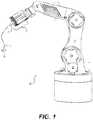
- FIG. 1is a diagrammatic illustration of an exemplary disclosed additive manufacturing system
- FIGS. 2-5are diagrammatic illustrations of exemplary disclosed heads that may be used in conjunction with the system of FIG. 1 ;
- FIGS. 6 and 7are cross-sectional illustrations of exemplary nozzles that may be used in conjunction with the heads of FIGS. 2-5 .
- FIG. 1illustrates an exemplary system 10 , which may be used to continuously manufacture a composite structure 12 having any desired cross-sectional shape (e.g., circular, polygonal, etc.).
- System 10may include at least a support 14 and a head 16 .
- Head 16may be coupled to and moved by support 14 .
- support 14is a robotic arm capable of moving head 16 in multiple directions during fabrication of structure 12 , such that a resulting longitudinal axis of structure 12 is three-dimensional. It is contemplated, however, that support 14 could alternatively be an overhead gantry or a hybrid gantry/arm also capable of moving head 16 in multiple directions during fabrication of structure 12 .
- a drivemay mechanically couple head 16 to support 14 , and may include components that cooperate to move and/or supply power or materials to head 16 .
- Head 16may be configured to receive or otherwise contain a matrix.
- the matrixmay include any type of material (e.g., a liquid resin, such as a zero-volatile organic compound resin; a powdered metal; etc.) that is curable.
- Exemplary matrixesinclude thermosets, single- or multi-part epoxy resins, polyester resins, cationic epoxies, acrylated epoxies, urethanes, esters, thermoplastics, photopolymers, polyepoxides, thiols, alkenes, thiol-enes, and more.
- the matrix inside head 16may be pressurized, for example by an external device (e.g., an extruder or another type of pump—not shown) that is fluidly connected to head 16 via a corresponding conduit (not shown).
- the matrix pressuremay be generated completely inside of head 16 by a similar type of device.
- the matrixmay be gravity-fed through and/or mixed within head 16 .
- the matrix inside head 16may need to be kept cool and/or dark to inhibit premature curing; while in other instances, the matrix may need to be kept warm for the same reason. In either situation, head 16 may be specially configured (e.g., insulated, chilled, and/or warmed) to provide for these needs.
- the matrixmay be used to coat, encase, or otherwise at least partially surround any number of continuous reinforcements (e.g., separate fibers, tows, rovings, ribbons, and/or sheets of material) and, together with the reinforcements, make up at least a portion (e.g., a wall, a floor, a ceiling, a filling, etc.) of composite structure 12 .
- the reinforcementsmay be stored within (e.g., on separate internal spools—not shown) or otherwise passed through head 16 (e.g., fed from external spools).
- the reinforcementsmay be of the same type and have the same diameter and cross-sectional shape (e.g., circular, square, flat, etc.), or of a different type with different diameters and/or cross-sectional shapes.
- the reinforcementsmay include, for example, carbon fibers, vegetable fibers, wood fibers, mineral fibers, glass fibers, metallic wires, optical tubes, etc. It should be noted that the term “reinforcement” is meant to encompass both structural and non-structural types of continuous materials that can be at least partially encased in the matrix discharging from head 16 .
- the reinforcementsmay be exposed to (e.g., coated with) the matrix while the reinforcements are inside head 16 , while the reinforcements are being passed to head 16 (e.g., as a pre-preg material), and/or while the reinforcements are discharging from head 16 , as desired.
- the matrix, dry reinforcements, and/or reinforcements that are already exposed to the matrixmay be transported into head 16 in any manner apparent to one skilled in the art.
- the matrix alone, the reinforcement alone, and/or the matrix-wetted reinforcementmay be discharged from head 16 via at least two different modes of operation.
- a first mode of operationthe matrix and/or reinforcement are extruded (e.g., pushed under pressure and/or mechanical force) from head 16 , as head 16 is moved by support 14 to create the 3-dimensional shape of structure 12 .
- a second mode of operationat least the reinforcement is pulled from head 16 , such that a tensile stress is created in the reinforcement during discharge.
- the matrixmay cling to the reinforcement and thereby also be pulled from head 16 along with the reinforcement, and/or the matrix may be discharged from head 16 under pressure along with the pulled reinforcement.
- the resulting tension in the reinforcementmay increase a strength of structure 12 , while also allowing for a greater length of unsupported material to have a straighter trajectory (i.e., the tension may act against the force of gravity to provide free-standing support for structure 12 ).
- the reinforcementmay be pulled from head 16 as a result of head 16 moving away from an anchor point 18 .
- a length of matrix and/or matrix-impregnated reinforcementmay be adhered to anchor point 18 (e.g., via curing of the matrix).
- head 16may be moved away from anchor point 18 , and the relative movement may cause the reinforcement to be pulled from head 16 .
- the movement of the matrix and/or reinforcement through head 16could be assisted (e.g., via internal feed mechanisms), if desired.
- the discharge rate of the reinforcement from head 16may primarily be the result of relative movement between head 16 and anchor point 18 , such that tension is created within the reinforcement.
- anchor point 18could be moved away from head 16 instead of or in addition to head 16 being moved away from anchor point 18 .
- One or more cure enhancers(e.g., one or more light sources, an ultrasonic emitter, a laser, a heater, a catalyst dispenser, a microwave generator, a chiller, etc.) 20 may be mounted proximate (e.g., within, on, and/or trailing from) head 16 and configured to enhance a cure rate and/or quality of the matrix as it is discharged from head 16 .
- cure enhancer 20may be controlled to selectively expose internal and/or external surfaces of structure 12 to cure energy (e.g., light energy, electromagnetic radiation, vibrations, heat, a chemical catalyst or hardener, etc.) during the formation of structure 12 .
- cure energye.g., light energy, electromagnetic radiation, vibrations, heat, a chemical catalyst or hardener, etc.
- the energymay increase a rate of chemical reaction occurring within the matrix, sinter the material, harden the material, or otherwise cause the material to cure as it discharges from head 16 .
- cure enhancers 20may function to remove energy from the matrix, thereby causing the matrix to cool and harden.
- a controller 22may be provided and communicatively coupled with support 14 , head 16 , and any number and type of cure enhancers 20 .
- Controller 22may embody a single processor or multiple processors that include a means for controlling an operation of system 10 .
- Controller 22may include one or more general- or special-purpose processors or microprocessors.
- Controller 22may further include or be associated with a memory for storing data such as, for example, design limits, performance characteristics, operational instructions, matrix characteristics, reinforcement characteristics, characteristics of structure 12 , and corresponding parameters of each component of system 10 .
- Various other known circuitsmay be associated with controller 22 , including power supply circuitry, signal-conditioning circuitry, solenoid/motor driver circuitry, communication circuitry, and other appropriate circuitry.
- controller 22may be capable of communicating with other components of system 10 via wired and/or wireless transmission.
- One or more mapsmay be stored in the memory of controller 22 and used during fabrication of structure 12 .
- Each of these mapsmay include a collection of data in the form of models, lookup tables, graphs, and/or equations.
- the mapsare used by controller 22 to determine desired characteristics of cure enhancers 20 , the associated matrix, and/or the associated reinforcements at different locations within structure 12 .
- the characteristicsmay include, among others, a type, quantity, and/or configuration of reinforcement and/or matrix to be discharged at a particular location within structure 12 , and/or an amount, intensity, shape, and/or location of desired curing.
- Controller 22may then correlate operation of support 14 (e.g., the location and/or orientation of head 16 ) and/or the discharge of material from head 16 (a type of material, desired performance of the material, cross-linking requirements of the material, a discharge rate, etc.) with the operation of cure enhancers 20 , such that structure 12 is produced in a desired manner.
- support 14e.g., the location and/or orientation of head 16
- discharge of material from head 16a type of material, desired performance of the material, cross-linking requirements of the material, a discharge rate, etc.
- head 16may be used to fill a feature (e.g., a groove, a channel, a void, a recess, a crack, etc.) 24 within an existing component 26 .
- Component 26may include, for example, a body panel (e.g., a wing, a fuselage, a door, a hood, etc.) of a vehicle (not shown), a wall of a residential or commercial building, a pre-fabricated form that functions as a housing for structure 12 (e.g., in a wiring harness application), or another component known in the art. In any of these examples, component 26 may itself function as anchor point 18 , for use in fabrication of structure 12 within feature 24 .
- Feature 24may be formed in advance by way of an integral molding process, an integral additive manufacturing process, a subtractive process (e.g., a milling, grinding, or cutting process), unintentional damage (e.g., as a crack), and/or in other ways.
- a subtractive processe.g., a milling, grinding, or cutting process
- unintentional damagee.g., as a crack
- the fabrication of structure 12 within feature 24may completely fill and/or seal feature 24 .
- an additional processmay be implemented to top-off and/or seal feature 24 after fabrication of structure 12 inside of feature 24 , if desired.
- head 16may include, among other things, a matrix reservoir 28 , and one or more nozzles 30 fluidly connected to matrix reservoir 28 .
- nozzle 30has a single-path configuration that discharges composite material having a generally circular cross-section.
- the configuration of head 16may allow nozzle 30 to be swapped out for another nozzle (not shown) that discharges matrix only, reinforcement only, and/or composite material having any desired shape (e.g., a tubular cross-section, a linear or flat cross-section, a box-shaped cross-section, a multi-channel shape, etc.).
- matrix reservoir 28is shown as communicating with nozzle 30 via an opening 32 .
- matrix reservoir 28has a generally circular cross-section, and tapers radially inward to opening 32 .
- a size (e.g., diameter and/or height) of matrix reservoir 28may be sufficient to hold a supply of matrix material (represented as M in FIG. 2 ) necessary for wetting any associated reinforcements (represented as R in FIG. 6 ) passing through nozzle 30 .
- a size of nozzle 30(e.g., an outer diameter or width) at a tip end may be designed to accommodate features 24 having a particular width at an outer surface of component 26 .
- nozzle 30may be sized to be larger than the width of feature 24 , such that nozzle 30 may straddle feature 24 and extend radially outward past opposing edges of feature 24 .
- the tip end (e.g., opposing sides of a corresponding end surface) of nozzle 30may contact (e.g., ride along) the upper surface of component 26 .
- an axis of nozzle 30may generally remain normal to an axis of feature 24 during fabrication.
- these spatial and orientation relationshipsmay help to pull more matrix (e.g., about 20% more) from nozzle 30 than would otherwise be possible.
- the matrix(together with any associated reinforcement) may fill feature 24 completely.
- a spacemay be intentionally left at an exposed side of feature 24 , such that another material may be deposited adjacent the cured matrix and thereby seal off feature 24 . It is also contemplated that, even when the cured matrix completely fills feature 24 , the other material could still be deposited adjacent an exposed side of the cured matrix to function as a cap or cover, if desired.
- Head 16may be moved by support 14 to follow a pre-programmed path associated with feature 24 , thereby allowing nozzle 30 to fill feature 24 with material. In some applications, it may be beneficial to assist and/or alternatively control movements of head 16 with a detected location of feature 24 .
- a guide 34may be used for this purpose. It should be noted that, although guide 34 is shown as being connected to head 16 , guide 34 could alternatively be located offboard head 16 (e.g., connected directly to support 14 or connected to an independent support—not shown).
- guide 34is a mechanical device having a protrusion 36 that extends from a leading side of head 16 into feature 24 .
- Protrusion 36may be configured to physically engage a portion of feature 24 (e.g., one side wall, both opposing side walls, a bottom, etc.), and an associated sensing mechanism 38 may generate a signal indicative of a real-time trajectory relationship between nozzle 30 and feature 24 .
- the signalmay be directed to controller 22 , which may responsibly regulate operation of support 14 and movement of head 16 during fabrication of structure 12 to maintain nozzle 30 at a desired location and orientation relative to feature 24 .
- compactingmay provide for a greater density of reinforcements, situate the reinforcements at a desired location (e.g., at a center) within the matrix, and/or provide a desired texture to an outer surface of the material.
- this compactionis provided by way of a shoe 40 that trails behind nozzle 30 (e.g., between nozzle 30 and cure enhancer 20 ). It is contemplated, however, that another device (e.g., a compaction wheel) could additionally or alternatively be used for this purpose, if desired.
- Shoe 40may be biased (e.g., via a spring 42 —shown only in FIGS. 6 and 7 ) downward, to slide over the material discharging from nozzle 30 and/or over the upper surface of component 26 at the sides of feature 24 .
- shoe 40is shown as having a generally flat bottom surface that spans at least the full width of feature 24 , it is contemplated that shoe 40 could have another shape that produces a non-planar surface and/or that feature 24 could have a narrower width that allows shoe 40 to travel within feature 24 , if desired.
- shoe 40may function as a die, imparting a desired shape into the discharging material.
- a vibration actuator(e.g., a linear resonant actuator—not shown) that generates oscillations of shoe 40 in a direction normal to a trajectory of the discharging material (e.g., in an axial direction of nozzle 30 ), may be utilized in some applications, to improve compaction, reduce porosity, and/or provide a desired surface texture.
- a frequency of the oscillations generated with shoe 40may be in the ultrasonic range (e.g., at least 20,000 Hz).
- FIG. 3Another exemplary head 16 that may be used to fill feature 24 within component 26 is illustrated in FIG. 3 .
- feature 24is not originally an integral part of component 26 .
- feature 24must first be fabricated through a subtraction process, prior to the additive process of filling feature 24 with composite material.
- a trajectory of feature 24may be designed to provide a desired functionality (e.g., to provide even heating of an airfoil, to provide distributed load sensing, etc.) within the existing component 26 .
- the trajectory of feature 24may be defined, at least in part, by damage sustained within component 26 (e.g., to cut away damaged material, such that a uniform cross-section and/or depth of feature 24 is achieved along an existing crack trajectory). Head 16 of FIG.
- a cutting mechanism 44may be operatively connected to head 16 .
- cutting mechanism 44is a rotary blade. It is contemplated, however, that a router bit, a laser, a torch, or another type of cutting mechanism known in the art could alternatively be employed, if desired.
- Cutting mechanism 44may be positioned in front of guide 34 , such that guide 34 detects surfaces generated by cutting mechanism 44 . Alternatively, guide 34 may be eliminated in some situations, as cutting mechanism 44 may perform functions similar to those performed by guide 34 .
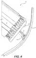
- Head 16 of FIG. 4may also include cutting mechanism 44 .
- cutting mechanism 44 of FIG. 4may be integral with nozzle 30 (e.g., instead of spaced apart in front of nozzle 30 ).
- the example shown in FIG. 4includes a sharped blade at a leading side of nozzle 30 .
- the sharpened blademay be heated and/or vibrated to reduce an effort required to cut through the outer surface of component 26 . It is contemplated that, instead of removing material from component 26 , cutting mechanism 44 of FIG.
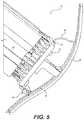
- Head 16 of FIG. 5illustrates a configuration having a no-contact type of guide located at the leading side of nozzle 16 .
- head 16may include a scanner 46 configured to detect a location and/or characteristics (e.g., depth, width, contour, etc.) of feature 24 . Scanner 46 may then generate signals directed to controller 22 (referring to FIG. 1 ), allowing controller 22 to responsively adjust movement and/or operation of head 16 . It is contemplated that scanner 46 could be used in conjunction with guide 34 , if desired. In this example, guide 34 would be located at a trailing side of nozzle 30 , opposite scanner 46 . The use of guide 34 together with scanner 46 may allow for more precise positioning control over nozzle 30 .
- a scanner 46configured to detect a location and/or characteristics (e.g., depth, width, contour, etc.) of feature 24 . Scanner 46 may then generate signals directed to controller 22 (referring to FIG. 1 ), allowing controller 22 to responsively adjust movement and/or operation of head 16 . It
- scanner 46could function to provide feedback regarding how the material discharging from nozzle 30 is filling feature 24 . Controller 22 could then use the signals from scanner 46 to dynamically adjust operation of head 16 .
- FIGS. 6 and 7illustrate cross-sections of exemplary nozzle 30 that may be used to fill and/or seal feature 24 .
- nozzle 30may have multiple channels 48 each configured to discharge a distinct track of material (e.g., matrix, reinforcement, wetted-reinforcement, etc.).
- the tracks of materialmay be discharged at different times such that only a single track is compacted by shoe 40 , or at the same time such that the tracks overlap each other are compressed together into a common layer of structure 12 .
- four different channels 48are shown, including a thermoset channel 48 a , a first reinforcement channel 48 b , a second reinforcement channel 48 c , and a thermoplastic channel 48 d .
- Thermoset channel 48 amay be located at a leading side of nozzle 30 ; thermoplastic channel 48 d may be located at a trailing side of nozzle 30 , and first and second reinforcement channels 48 c , 48 d may be located sequentially between thermoset and thermoplastic channels 48 a , 48 d . It should be noted that any number of channels 48 could be included and arranged into any particular configuration.
- Thermoset channel 48 amay be configured to discharge a reinforcement (e.g., fiberglass) that has been wetted with a thermoset epoxy or the thermoset epoxy alone (e.g., an epoxy contained within matrix reservoir 28 ).
- First reinforcement channel 48 bmay be configured to discharge a matrix-wetted or dry reinforcement of a first size.
- Second reinforcement channel 48 cmay be configured to discharge a matrix-wetted or dry reinforcement of a second size.
- first and second reinforcement channelsare fluidly isolated from matrix reservoir 28 . It is contemplated, however, that one or both of first and second reinforcement channels 48 b , 48 c could be fluidly connected to matrix reservoir 28 , if desired.
- Thermoplastic channel 48 dmay be configured to discharge a thermoplastic matrix only or a thermoplastic-wetted reinforcement.
- Thermoplastic channel 48 dmay be fluidly isolated from matrix reservoir 28 .
- a trailing edge of each channel 48may be rounded to reduce breakage of any associated reinforcements.
- thermoset-wetted reinforcement discharging from channel 48 amay form a bed within feature 24 for one or both of the reinforcements subsequently discharged from channels 48 b and/or 48 c .
- thermoset epoxiesmay not always readily coat and/or cling to metallic wires and/or optical tubes.
- the thermoplastic material discharging from channel 48 dmay be substantially identical to the material making up component 26 (or at least formulated to readily bond with the component material in a desirable manner), thereby allowing for sealing of feature 24 .
- thermoset epoxymay primarily be due to the UV light from cure enhancers 20 . Accordingly, the thermoset epoxy may need to be exposed to the UV light prior to the epoxy being covered and sealed by the thermoplastic matrix.
- head 16 of FIG. 7includes cure enhancer(s) 20 located between thermoset channel 48 a and thermoplastic channel 48 d (e.g., upstream, between, and/or downstream of first and/or second reinforcement channels 48 a and 48 b ).
- thermoset channel 48 amay also need to be insulated from thermoplastic channel 48 d , such that the heat associated with thermoplastic channel 48 d , such that premature curing does not happen.
- An air gap 56may provide at least some of this insulation.
- one or more of channels 48may be pivotally connected to each other (e.g., via one or more hinges 58 ). Hinge(s) 58 may allow for a sharper turn radius of nozzle 30 .
- one or more of channels 48are features of a monolithic nozzle body.
- the heatmay be provided via a separate heating mechanism 50 that is associated with thermoplastic channel 48 d .
- heatmay be conducted from heating mechanism 50 to a thermoplastic feedstock passing through channel 48 , causing the feedstock to soften and/or melt within nozzle 30 .
- Some of this heatmay also be conducted toward channel 48 a , allowing the associated thermoset epoxy within channel 48 a to warm to an initiation threshold just prior to discharge from nozzle 30 .
- this heatalone, may be sufficient to fully cure the thermoset epoxy.
- cure enhancers 20may still be utilized and curing may simply be assisted by the heat from mechanism 50 .
- one or more of the reinforcements within structure 12could be electrically charged during fabrication of structure 12 .
- a first end (e.g., an end already placed into feature 24 ) of one or more of the reinforcementscould be grounded, while a second end (e.g., an end within a supply located upstream of or inside of head 16 ) could be charged.
- a currentwould then pass from the second end to the first end, causing the reinforcement to heat.
- the heat from this reinforcementwould then be conducted into the surrounding thermoset epoxy, facilitating curing thereof.
- Component 26may benefit from reinforcements of different sizes at different locations within feature 24 .
- controller 22(referring to FIG. 1 ) may be configured to selectively cause only the first reinforcement, only the second reinforcement, or both the first and second reinforcements to be advanced out of channels 48 a and/or 48 b .
- one or more feed mechanismse.g., roller sets, plungers, jets, etc.
- feed mechanisms 52may be associated with each channel 48 , and configured to advance the associated material through channel 48 in response to a command generated by controller 22 .
- controller 22may selectively cause a cutter (e.g., an ultrasonic blade, a rotary device, a laser, etc.) 54 to sever one or more of the reinforcements. It is contemplated that the same cutter 54 may be used to sever multiple reinforcements (e.g., to pivot between adjacent reinforcements), if desired. After a particular reinforcement has been severed, controller 22 may cause the associated feed mechanism 52 to retract the reinforcement (e.g., a distance back inside of the corresponding channel 48 b or 48 c ).
- a cuttere.g., an ultrasonic blade, a rotary device, a laser, etc.
- the reinforcement being discharged through any channel 48may have unique characteristics that allow for increased functionality within structure 12 .
- the reinforcementmay include one or more functional elements 60 connected to or otherwise forming an integral portion of the reinforcement.
- Functional elements 60may include, for example, resisters, capacitors, light-emitting diodes (LED), RFID tags, switches, batteries, fuses, filters (e.g., low-pass filters), etc.
- a particular reinforcementmay have, at a particular axial distance along its length, an LED that is integrally joined between opposing first and second ends. At this location, the LED may function as a continuity indicator, for example, illuminating any time a current of a minimum magnitude passes from the first end to the second end.
- Functional elements 60may become an integral portion of the reinforcements prior to the reinforcements passing through head 16 .
- the material discharging from channel 48 dincludes a reinforcement that is braided and/or is made from a metallic foil (e.g., a solid or perforated foil), as well as a thermoset matrix having suspended metallic particles and/or that is electrically conductive and grounded at particular locations. It is also contemplated that the thermoset matrix may be transparent at particular locations, such that the functional elements 60 described above may be observed.
- a metallic foile.g., a solid or perforated foil
- thermoset matrixhaving suspended metallic particles and/or that is electrically conductive and grounded at particular locations. It is also contemplated that the thermoset matrix may be transparent at particular locations, such that the functional elements 60 described above may be observed.
- the disclosed system, head, and nozzlemay be used to impart functionality to existing structures.
- wiring harnesses, electrical grids, sensors, heaters, etc.may be embedded into the skins of existing automobiles, aircraft, watercraft, and other types of machine, where light-weight, low-cost, small-footprint, and high-performance are important.
- These functional elementsmay be embedded at low-cost, due to the reduction in dedicated tooling for each configuration, and due to the ability to redesign and make on-the-fly adjustments.
- the associated components embedded into the machinesmay have a low footprint, because they are fabricated directly in place on machine 12 .
- the disclosed systemmay impart high-performance due to the unique ways that particular reinforcements, functional elements 60 , and matrix materials can be used and laid out within the components. Operation of system 10 will now be described in detail, with reference to FIGS. 1-7 .
- system 10may be loaded into system 10 (e.g., into controller 22 that is responsible for regulating operation of support 14 , cure enhancer(s) 20 , shoe 40 , heating mechanism 50 , feed mechanisms 52 , cutter 54 , and/or any other associated components).
- This informationmay include, among other things, a size (e.g., diameter, wall thickness, length, etc.), a contour (e.g., a trajectory), surface features (e.g., ridge size, location, thickness, length; flange size, location, thickness, length; etc.), connector geometry (e.g., locations and sizes of couplings, tees, splices, etc.), location-specific matrix stipulations, location-specific reinforcement stipulations, location-specific conductor stipulations, desired cure rates, cure locations, cure shapes, cure amounts, surface contours, etc. It should be noted that this information may alternatively or additionally be loaded into system 10 at different times and/or continuously during the manufacturing event, if desired.
- a sizee.g., diameter, wall thickness, length, etc.
- a contoure.g., a trajectory
- surface featurese.g., ridge size, location, thickness, length; flange size, location, thickness, length; etc.
- reinforcements and/or matrix materialsmay be selectively installed within system 10 and/or continuously supplied into print head 16 .
- the corresponding reinforcementse.g., prepreg or dry fibers, tows, ribbons, sheets, wires, optical tubes, etc.
- the corresponding reinforcementsmay be threaded through matrix reservoir 28 and/or channels 48 of print head 16 and nozzle 30 , and thereafter connected to a pulling machine (not shown) and/or to a mounting fixture (e.g., to anchor point 18 and/or feature 24 ).
- Installation of the matrix materialmay include filling matrix reservoir 28 with resin and/or directing feedstock into channel 48 d.
- Print head 16may be moved by support 14 under the regulation of controller 22 to cause matrix only, reinforcement only, and/or matrix-coated reinforcements to be placed against a surface of feature 24 and/or on a corresponding anchor point 18 .
- Cure enhancers 20may then be selectively activated to cause hardening of the matrix material(s), thereby bonding the reinforcements to anchor point 18 and/or feature 24 .
- activation of cure enhancers 20may be unnecessary, and heat from heating mechanism 50 may be sufficient for initial anchoring.
- the component, feature, and/or materials informationmay then be used to control operation of system 10 .
- the reinforcement(s)may be submerged within associated matrixes, and pulled through the corresponding channels 48 to at least partially fill feature 24 .
- head 16may additionally fabricate feature 24 prior to filling, in some applications.
- Controller 22may selectively cause support 14 to move print head 16 in a desired manner at this time (e.g., based on input and/or feedback from guide 34 and/or scanner 46 ), such that the discharging composite material follows a desired trajectory inside of feature 24 .
- cure enhancers 20may be selectively activated by controller 22 during material discharge to initiate, speed up, or complete hardening of the matrix material.
- feature 24is filled with thermoset matrix, fibers, wires, and/or optical tubes, the exposed side of feature 24 may be sealed off with thermoset matrix (and additional reinforcements, if desired).
- nozzle 30may be oriented generally normal to the surface of component 26 , and ride along sides of feature 24 . This may allow matrix located at the tip end of nozzle 30 to contact walls of feature 24 . This contact may result in extra (e.g., up to about 20% extra) matrix being drawn out of nozzle 30 than would normally be pulled out by movement of reinforcement only.
- the reinforcementsmay be disconnected (e.g., severed) from print head 16 in any desired manner.
- the severed ends of the reinforcement(s)may then be joined to connectors (e.g., power sources, grounds, etc.), if desired, thereby completing fabrication of component 26 .
Landscapes
- Engineering & Computer Science (AREA)
- Chemical & Material Sciences (AREA)
- Materials Engineering (AREA)
- Mechanical Engineering (AREA)
- Manufacturing & Machinery (AREA)
- Composite Materials (AREA)
- Physics & Mathematics (AREA)
- Optics & Photonics (AREA)
- Robotics (AREA)
Abstract
Description
Claims (16)
Priority Applications (1)
| Application Number | Priority Date | Filing Date | Title |
|---|---|---|---|
| US15/858,236US11167495B2 (en) | 2017-12-29 | 2017-12-29 | System and method for additively manufacturing functional elements into existing components |
Applications Claiming Priority (1)
| Application Number | Priority Date | Filing Date | Title |
|---|---|---|---|
| US15/858,236US11167495B2 (en) | 2017-12-29 | 2017-12-29 | System and method for additively manufacturing functional elements into existing components |
Publications (2)
| Publication Number | Publication Date |
|---|---|
| US20190202131A1 US20190202131A1 (en) | 2019-07-04 |
| US11167495B2true US11167495B2 (en) | 2021-11-09 |
Family
ID=67059179
Family Applications (1)
| Application Number | Title | Priority Date | Filing Date |
|---|---|---|---|
| US15/858,236Active2040-07-08US11167495B2 (en) | 2017-12-29 | 2017-12-29 | System and method for additively manufacturing functional elements into existing components |
Country Status (1)
| Country | Link |
|---|---|
| US (1) | US11167495B2 (en) |
Cited By (1)
| Publication number | Priority date | Publication date | Assignee | Title |
|---|---|---|---|---|
| US12391010B2 (en) | 2023-01-13 | 2025-08-19 | Rtx Corporation | Methods of manufacture for composite blades |
Families Citing this family (5)
| Publication number | Priority date | Publication date | Assignee | Title |
|---|---|---|---|---|
| US10766594B2 (en)* | 2016-11-03 | 2020-09-08 | Continuous Composites Inc. | Composite vehicle body |
| US10933600B2 (en)* | 2018-03-08 | 2021-03-02 | The Boeing Company | Three-dimensional printing of composite repair patches and structures |
| US20220371274A1 (en)* | 2018-11-19 | 2022-11-24 | Continuous Composites Inc. | System for additively manufacturing composite structure |
| US11420390B2 (en)* | 2018-11-19 | 2022-08-23 | Continuous Composites Inc. | System for additively manufacturing composite structure |
| CN114901457A (en)* | 2020-01-02 | 2022-08-12 | 9T实验室股份公司 | Apparatus and method for applying elongated fiber tows |
Citations (175)
| Publication number | Priority date | Publication date | Assignee | Title |
|---|---|---|---|---|
| US3286305A (en) | 1964-09-03 | 1966-11-22 | Rexall Drug Chemical | Apparatus for continuous manufacture of hollow articles |
| US3809514A (en) | 1971-11-13 | 1974-05-07 | Castro Nunez Elem Huecos | Machine for the continuous manufacture of hollow elements |
| US3984271A (en) | 1973-06-25 | 1976-10-05 | Owens-Corning Fiberglas Corporation | Method of manufacturing large diameter tubular structures |
| US3993726A (en) | 1974-01-16 | 1976-11-23 | Hercules Incorporated | Methods of making continuous length reinforced plastic articles |
| US4643940A (en) | 1984-08-06 | 1987-02-17 | The Dow Chemical Company | Low density fiber-reinforced plastic composites |
| US4671761A (en) | 1984-06-30 | 1987-06-09 | Fried. Krupp Gesellschaft Mit Beschrankter Haftung | Apparatus for producing reinforced elongate bodies |
| US4822548A (en) | 1986-06-13 | 1989-04-18 | Firma Carl Freudenberg | Method and apparatus for manufacturing a thread-reinforced rubber hose |
| US4851065A (en) | 1986-01-17 | 1989-07-25 | Tyee Aircraft, Inc. | Construction of hollow, continuously wound filament load-bearing structure |
| US5002712A (en) | 1988-10-19 | 1991-03-26 | Bayer Aktiengesellschaft | Manufacturing composite materials |
| US5037691A (en) | 1986-09-15 | 1991-08-06 | Compositech, Ltd. | Reinforced plastic laminates for use in the production of printed circuit boards and process for making such laminates and resulting products |
| DE4102257A1 (en) | 1991-01-23 | 1992-07-30 | Artos Med Produkte | Appts. for mfg. reinforced components in laser-cured polymer - has laser-curable polymer in bath, laser directed at polymer surface where fibres pass through polymer and are guided relative to laser beam angle |
| US5296335A (en) | 1993-02-22 | 1994-03-22 | E-Systems, Inc. | Method for manufacturing fiber-reinforced parts utilizing stereolithography tooling |
| US5340433A (en) | 1989-10-30 | 1994-08-23 | Stratasys, Inc. | Modeling apparatus for three-dimensional objects |
| US5746967A (en) | 1995-06-26 | 1998-05-05 | Fox Lite, Inc. | Method of curing thermoset resin with visible light |
| US5866058A (en) | 1997-05-29 | 1999-02-02 | Stratasys Inc. | Method for rapid prototyping of solid models |
| US5936861A (en) | 1997-08-15 | 1999-08-10 | Nanotek Instruments, Inc. | Apparatus and process for producing fiber reinforced composite objects |
| US6153034A (en) | 1997-08-03 | 2000-11-28 | Micromod R.P. Ltd | Rapid prototyping |
| US20020009935A1 (en) | 1999-03-23 | 2002-01-24 | Hexcel Corporation | Core-crush resistant fabric and prepreg for fiber reinforced composite sandwich structures |
| US20020062909A1 (en) | 2000-11-29 | 2002-05-30 | Jang Bor Z. | Layer-additive method and apparatus for freeform fabrication of 3-D objects |
| US20020113331A1 (en) | 2000-12-20 | 2002-08-22 | Tan Zhang | Freeform fabrication method using extrusion of non-cross-linking reactive prepolymers |
| US6459069B1 (en) | 1996-11-22 | 2002-10-01 | Joshua E. Rabinovich | Rapid manufacturing system for metal, metal matrix composite materials and ceramics |
| US20020165304A1 (en) | 2000-12-04 | 2002-11-07 | Mulligan Anthony C. | Methods and appratus for preparation of three-dimensional bodies |
| US6501554B1 (en) | 2000-06-20 | 2002-12-31 | Ppt Vision, Inc. | 3D scanner and method for measuring heights and angles of manufactured parts |
| US20030044539A1 (en) | 2001-02-06 | 2003-03-06 | Oswald Robert S. | Process for producing photovoltaic devices |
| US20030056870A1 (en) | 2001-09-21 | 2003-03-27 | Stratasys, Inc. | High-precision modeling filament |
| US20030160970A1 (en) | 2002-01-30 | 2003-08-28 | Anup Basu | Method and apparatus for high resolution 3D scanning |
| US20030186042A1 (en) | 2002-05-07 | 2003-10-02 | Dunlap Earl N. | Process for tempering rapid prototype parts |
| US20030236588A1 (en) | 2002-03-14 | 2003-12-25 | Jang Bor Z. | Nanotube fiber reinforced composite materials and method of producing fiber reinforced composites |
| US6799081B1 (en) | 2000-11-15 | 2004-09-28 | Mcdonnell Douglas Corporation | Fiber placement and fiber steering systems and corresponding software for composite structures |
| US6803003B2 (en) | 2000-12-04 | 2004-10-12 | Advanced Ceramics Research, Inc. | Compositions and methods for preparing multiple-component composite materials |
| US20050006803A1 (en) | 2001-05-17 | 2005-01-13 | Owens Charles R. | Preform for manufacturing a material having a plurality of voids and method of making the same |
| US20050061422A1 (en) | 2003-09-22 | 2005-03-24 | Martin James P. | Multiple tape laying apparatus and method |
| US20050104257A1 (en) | 2003-09-04 | 2005-05-19 | Peihua Gu | Multisource and multimaterial freeform fabrication |
| US20050109451A1 (en) | 2003-11-20 | 2005-05-26 | Hauber David E. | Composite tape laying apparatus and method |
| US20050230029A1 (en) | 2001-01-02 | 2005-10-20 | Advanced Ceramics Research, Inc. | Continuous fiber reinforced composites and methods, apparatuses, and compositions for making the same |
| US7039485B2 (en) | 2004-03-12 | 2006-05-02 | The Boeing Company | Systems and methods enabling automated return to and/or repair of defects with a material placement machine |
| US20070003650A1 (en) | 2001-03-01 | 2007-01-04 | Schroeder Ernest C | Apparatus for fabricating fiber reinforced plastic parts |
| US20070228592A1 (en) | 2006-04-03 | 2007-10-04 | Stratasys, Inc. | Auto tip calibration in an extrusion apparatus |
| US20090095410A1 (en) | 2007-10-16 | 2009-04-16 | Ingersoll Machine Tools, Inc. | Fiber Placement Machine Platform System Having Interchangeable Head and Creel Assemblies |
| US7555404B2 (en) | 2007-08-09 | 2009-06-30 | The Boeing Company | Methods and systems for automated ply boundary and orientation inspection |
| US7795349B2 (en) | 1999-11-05 | 2010-09-14 | Z Corporation | Material systems and methods of three-dimensional printing |
| KR100995983B1 (en) | 2008-07-04 | 2010-11-23 | 재단법인서울대학교산학협력재단 | Cross-printing method and apparatus of circuit board |
| US20110032301A1 (en) | 2004-09-21 | 2011-02-10 | Z Corporation | Apparatus and methods for servicing 3d printers |
| US20110143108A1 (en) | 2008-05-09 | 2011-06-16 | Fit Fruth Innovative Technologien Gmbh | Fibers and methods for use in solid freeform fabrication |
| US20120060468A1 (en) | 2010-09-13 | 2012-03-15 | Experimental Propulsion Lab, Llc | Additive manufactured propulsion system |
| US20120159785A1 (en) | 2009-09-04 | 2012-06-28 | BayerMaerialScience LLC | Automated processes for the production of polyurethane wind turbine blades |
| US8221669B2 (en) | 2009-09-30 | 2012-07-17 | Stratasys, Inc. | Method for building three-dimensional models in extrusion-based digital manufacturing systems using ribbon filaments |
| KR101172859B1 (en) | 2010-10-04 | 2012-08-09 | 서울대학교산학협력단 | Ultra precision machining apparatus using nano-scale three dimensional printing and method using the same |
| US20120231225A1 (en) | 2010-09-17 | 2012-09-13 | Stratasys, Inc. | Core-shell consumable materials for use in extrusion-based additive manufacturing systems |
| US20120247655A1 (en) | 2009-11-13 | 2012-10-04 | Karlsruher Institut Fuer Technologie | Method for producing a component from a fiber-reinforced material |
| WO2013017284A2 (en) | 2011-08-04 | 2013-02-07 | Arburg Gmbh + Co. Kg | Method and device for producing a three-dimensional object comprising a fiber feed |
| US20130164498A1 (en) | 2011-12-21 | 2013-06-27 | Adc Acquisition Company | Thermoplastic composite prepreg for automated fiber placement |
| US20130209600A1 (en) | 2012-02-10 | 2013-08-15 | Adam Perry Tow | Multi-axis, multi-purpose robotics automation and quality adaptive additive manufacturing |
| US20130233471A1 (en) | 2012-03-08 | 2013-09-12 | Randall A. Kappesser | Small flat composite placement system |
| US20130292039A1 (en) | 2012-04-04 | 2013-11-07 | Massachusetts Institute Of Technology | Methods and Apparatus for Actuated Fabricator |
| US20130337265A1 (en) | 2012-06-19 | 2013-12-19 | EADS UK Limited British | Thermoplastic polymer powder |
| US20130337256A1 (en) | 2012-06-19 | 2013-12-19 | Eads Uk Limited | Extrusion-based additive manufacturing system |
| US20140034214A1 (en) | 2012-07-31 | 2014-02-06 | Makerbot Industries, Llc | Build material switching |
| US20140061974A1 (en) | 2012-08-29 | 2014-03-06 | Kenneth Tyler | Method and apparatus for continuous composite three-dimensional printing |
| US20140159284A1 (en) | 2012-12-07 | 2014-06-12 | Stratasys, Inc. | Liquefier assembly for use in additive manufacturing system |
| US20140232035A1 (en) | 2013-02-19 | 2014-08-21 | Hemant Bheda | Reinforced fused-deposition modeling |
| US20140268604A1 (en) | 2013-03-14 | 2014-09-18 | Board Of Regents, The University Of Texas System | Methods and Systems For Embedding Filaments in 3D Structures, Structural Components, and Structural Electronic, Electromagnetic and Electromechanical Components/Devices |
| US20140291886A1 (en) | 2013-03-22 | 2014-10-02 | Gregory Thomas Mark | Three dimensional printing |
| US8962717B2 (en) | 2012-08-20 | 2015-02-24 | Basf Se | Long-fiber-reinforced flame-retardant polyesters |
| US20150136455A1 (en) | 2013-11-15 | 2015-05-21 | Robert J. Fleming | Shape forming process and application thereof for creating structural elements and designed objects |
| US20150174824A1 (en)* | 2013-12-19 | 2015-06-25 | Karl Joseph Gifford | Systems and methods for 3D printing with multiple exchangeable printheads |
| US9126365B1 (en) | 2013-03-22 | 2015-09-08 | Markforged, Inc. | Methods for composite filament fabrication in three dimensional printing |
| US9126367B1 (en) | 2013-03-22 | 2015-09-08 | Markforged, Inc. | Three dimensional printer for fiber reinforced composite filament fabrication |
| US9149988B2 (en) | 2013-03-22 | 2015-10-06 | Markforged, Inc. | Three dimensional printing |
| US9156205B2 (en) | 2013-03-22 | 2015-10-13 | Markforged, Inc. | Three dimensional printer with composite filament fabrication |
| US9186846B1 (en) | 2013-03-22 | 2015-11-17 | Markforged, Inc. | Methods for composite filament threading in three dimensional printing |
| US9186848B2 (en) | 2013-03-22 | 2015-11-17 | Markforged, Inc. | Three dimensional printing of composite reinforced structures |
| US20150367576A1 (en)* | 2014-06-19 | 2015-12-24 | Autodesk, Inc. | Automated systems for composite part fabrication |
| US20160012935A1 (en) | 2014-07-11 | 2016-01-14 | Empire Technology Development Llc | Feedstocks for additive manufacturing and methods for their preparation and use |
| EP2589481B1 (en) | 2011-11-04 | 2016-01-20 | Ralph Peter Hegler | Device for continuously manufacturing a composite pipe with connection sleeve |
| US20160031155A1 (en) | 2014-07-29 | 2016-02-04 | Cc3D Llc | Method and Apparatus for Additive Mechanical Growth of Tubular Structures |
| US20160046082A1 (en) | 2014-08-12 | 2016-02-18 | Airbus Operations Gmbh | Apparatus and method for manufacturing components from a fiber-reinforced composite material |
| US20160052208A1 (en) | 2014-08-21 | 2016-02-25 | Mosaic Manufacturing Ltd. | Series enabled multi-material extrusion technology |
| US20160082659A1 (en) | 2014-09-18 | 2016-03-24 | The Boeing Company | Extruded Deposition of Polymers Having Continuous Carbon Nanotube Reinforcements |
| US20160082641A1 (en) | 2014-09-18 | 2016-03-24 | The Boeing Company | Extruded Deposition of Fiber Reinforced Polymers |
| US20160107379A1 (en) | 2013-03-22 | 2016-04-21 | Markforged, Inc. | Composite filament 3d printing using complementary reinforcement formations |
| US20160114532A1 (en) | 2013-05-31 | 2016-04-28 | United Technologies Corporation | Continuous fiber-reinforced component fabrication |
| US20160136885A1 (en) | 2014-11-14 | 2016-05-19 | Cole Nielsen-Cole | Additive manufacturing techniques and systems to form composite materials |
| WO2016088048A1 (en) | 2014-12-01 | 2016-06-09 | Sabic Global Technologies B.V. | Rapid nozzle cooling for additive manufacturing |
| WO2016088042A1 (en) | 2014-12-01 | 2016-06-09 | Sabic Global Technologies B.V. | Additive manufacturing process automation systems and methods |
| US9370896B2 (en) | 2013-06-05 | 2016-06-21 | Markforged, Inc. | Methods for fiber reinforced additive manufacturing |
| US9381702B2 (en) | 2013-03-15 | 2016-07-05 | Seriforge Inc. | Composite preforms including three-dimensional interconnections |
| US20160192741A1 (en) | 2015-01-05 | 2016-07-07 | Markforged, Inc. | Footwear fabrication by composite filament 3d printing |
| WO2016110444A1 (en) | 2015-01-09 | 2016-07-14 | Daher Aerospace | Method for producing a complex composite part, in particular having a thermoplastic matrix, and part obtained by such a method |
| US20160243762A1 (en) | 2013-11-15 | 2016-08-25 | Fleming Robert J | Automated design, simulation, and shape forming process for creating structural elements and designed objects |
| US20160263806A1 (en) | 2013-10-30 | 2016-09-15 | Laing O'rourke Australia Pty Limited | Method for fabricating an object |
| US20160263822A1 (en) | 2013-10-30 | 2016-09-15 | R. Platt Boyd, IV | Additive manufacturing of building and other structures |
| US20160263823A1 (en) | 2015-03-09 | 2016-09-15 | Frederick Matthew Espiau | 3d printed radio frequency absorber |
| US20160271876A1 (en) | 2015-03-22 | 2016-09-22 | Robert Bruce Lower | Apparatus and method of embedding cable in 3D printed objects |
| US9458955B2 (en) | 2012-07-20 | 2016-10-04 | Mag Aerospace Industries, Llc | Composite waste and water transport elements and methods of manufacture for use on aircraft |
| US9457521B2 (en) | 2011-09-01 | 2016-10-04 | The Boeing Company | Method, apparatus and material mixture for direct digital manufacturing of fiber reinforced parts |
| WO2016159259A1 (en) | 2015-03-31 | 2016-10-06 | キョーラク株式会社 | Filament resin molding, three-dimensional object fabrication method, and filament resin molding manufacturing method |
| US20160297104A1 (en) | 2013-11-19 | 2016-10-13 | Guill Tool & Engineering | Coextruded, multilayer and multicomponent 3d printing inputs field |
| US20160311165A1 (en) | 2013-03-22 | 2016-10-27 | Markforged, Inc. | Multiaxis fiber reinforcement for 3d printing |
| US20160325491A1 (en) | 2013-12-26 | 2016-11-10 | Texas Tech University System | Microwave-induced localized heating of cnt filled polymer composites for enhanced inter-bead diffusive bonding of fused filament fabricated parts |
| US20160332369A1 (en) | 2014-02-04 | 2016-11-17 | Samir Shah | Device and method of manufacturing customizable three-dimensional objects |
| US20160339633A1 (en) | 2014-01-17 | 2016-11-24 | Graphene 3D Lab Inc. | Fused filament fabrication using multi-segment filament |
| WO2016196382A1 (en) | 2015-06-01 | 2016-12-08 | Velo3D, Inc. | Three-dimensional printing and three-dimensional objects formed using the same |
| US20160361869A1 (en) | 2013-03-22 | 2016-12-15 | Markforged, Inc. | Three dimensional printer for fiber reinforced composite filament fabrication |
| US20160368255A1 (en) | 2015-06-19 | 2016-12-22 | Airbus Operations Gmbh | Method of manufacturing components, in particular elongated profile sections from band-shaped pre-impregnated fibers (prepreg) |
| US9539762B2 (en) | 2013-03-22 | 2017-01-10 | Markforged, Inc. | 3D printing with kinematic coupling |
| WO2017006324A1 (en) | 2015-07-09 | 2017-01-12 | Something3D Ltd. | Method and apparatus for three dimensional printing |
| US20170007366A1 (en) | 2015-07-07 | 2017-01-12 | Align Technology, Inc. | Direct fabrication of aligners for arch expansion |
| US20170007386A1 (en) | 2015-07-07 | 2017-01-12 | Align Technology, Inc. | Systems, apparatuses and methods for substance delivery from dental appliance |
| US20170007362A1 (en) | 2015-07-07 | 2017-01-12 | Align Technology, Inc. | Dental materials using thermoset polymers |
| US20170007359A1 (en) | 2015-07-07 | 2017-01-12 | Align Technology, Inc. | Direct fabrication of orthodontic appliances with variable properties |
| WO2017006178A1 (en) | 2015-07-07 | 2017-01-12 | Align Technology, Inc. | Systems, apparatuses and methods for substance delivery from dental appliances and for ornamental designs on dental appliances |
| US20170007365A1 (en) | 2015-07-07 | 2017-01-12 | Align Technology, Inc. | Direct fabrication of aligners with interproximal force coupling |
| US20170007368A1 (en) | 2015-07-07 | 2017-01-12 | Align Technology, Inc. | Direct fabrication of attachment templates with adhesive |
| US20170015060A1 (en) | 2015-07-17 | 2017-01-19 | Lawrence Livermore National Security, Llc | Additive manufacturing continuous filament carbon fiber epoxy composites |
| US20170015059A1 (en) | 2015-07-17 | 2017-01-19 | Lawrence Livermore National Securty, Llc | High performance, rapid thermal/uv curing epoxy resin for additive manufacturing of short and continuous carbon fiber epoxy composites |
| US20170021565A1 (en) | 2014-04-30 | 2017-01-26 | Magna International Inc. | Apparatus and process for forming three-dimensional objects |
| US20170028588A1 (en) | 2015-07-31 | 2017-02-02 | The Boeing Company | Systems and methods for additively manufacturing composite parts |
| US20170028633A1 (en) | 2015-07-31 | 2017-02-02 | The Boeing Company | Systems and methods for additively manufacturing composite parts |
| US20170028644A1 (en) | 2015-07-31 | 2017-02-02 | The Boeing Company | Systems and methods for additively manufacturing composite parts |
| US20170028623A1 (en) | 2015-07-31 | 2017-02-02 | The Boeing Company | Systems and methods for additively manufacturing composite parts |
| US20170028638A1 (en) | 2015-07-31 | 2017-02-02 | The Boeing Company | Systems and methods for additively manufacturing composite parts |
| US20170028628A1 (en) | 2015-07-31 | 2017-02-02 | The Boeing Company | Systems and methods for additively manufacturing composite parts |
| US20170028635A1 (en) | 2015-07-31 | 2017-02-02 | Boeing Co | Systems and methods for additively manufacturing composite parts |
| US20170030207A1 (en) | 2015-07-28 | 2017-02-02 | General Electric Company | Ply, method for manufacturing ply, and method for manufacturing article with ply |
| US20170036403A1 (en) | 2014-03-28 | 2017-02-09 | Ez Print, Llc | 3D Print Bed Having Permanent Coating |
| US9579851B2 (en) | 2013-03-22 | 2017-02-28 | Markforged, Inc. | Apparatus for fiber reinforced additive manufacturing |
| US20170057167A1 (en) | 2015-08-25 | 2017-03-02 | University Of South Carolina | Integrated robotic 3d printing system for printing of fiber reinforced parts |
| US20170057164A1 (en) | 2015-08-31 | 2017-03-02 | Colorado School Of Mines | Hybrid additive manufacturing method and apparatus made therefrom |
| US20170064840A1 (en) | 2015-08-24 | 2017-03-02 | Board Of Regents, The University Of Texas System | Method and apparatus for wire handling and embedding on and within 3d printed parts |
| US20170057181A1 (en) | 2015-08-25 | 2017-03-02 | The Boeing Company | Composite feedstock strips for additive manufacturing and methods of forming thereof |
| US20170057165A1 (en) | 2015-08-25 | 2017-03-02 | The Boeing Company | Composite feedstock strips for additive manufacturing and methods of forming thereof |
| WO2017051202A1 (en) | 2015-09-24 | 2017-03-30 | Victrex Manufacturing Limited | Polymeric materials |
| US20170106565A1 (en) | 2015-10-14 | 2017-04-20 | Northrop Grumman Systems Corporation | Continuous fiber filament for fused deposition modeling (fdm) additive manufactured (am) structures |
| US20170120519A1 (en) | 2013-03-22 | 2017-05-04 | Markforged, Inc. | Embedding 3d printed fiber reinforcement in molded articles |
| US20170129186A1 (en) | 2015-11-06 | 2017-05-11 | U.S.A. As Represented By The Administrator Of The National Aeronautics And Space Administration | Adhesion test station in an extrusion apparatus and methods for using the same |
| US20170129171A1 (en) | 2015-11-09 | 2017-05-11 | U.S.A. As Represented By The Administrator Of The National Aeronautics And Space Administration | Devices and Methods for Additive Manufacturing Using Flexible Filaments |
| US20170129182A1 (en) | 2015-11-05 | 2017-05-11 | U.S.A. As Represented By The Administrator Of The National Aeronautics And Space Administration | Cutting mechanism for carbon nanotube yarns, tapes, sheets and polymer composites thereof |
| US20170129170A1 (en) | 2015-11-06 | 2017-05-11 | U.S.A. As Represented By The Administrator Of The National Aeronautics And Space Administration | Method for the free form fabrication of articles out of electrically conductive filaments using localized heating |
| US20170129176A1 (en) | 2015-11-09 | 2017-05-11 | Nike, Inc. | Tack and Drag Printing |
| WO2017081253A1 (en) | 2015-11-12 | 2017-05-18 | Fraunhofer-Gesellschaft zur Förderung der angewandten Forschung e.V. | Device for additively manufacturing a component |
| US20170144375A1 (en) | 2015-11-20 | 2017-05-25 | The Boeing Company | System and method for cutting material in continuous fiber reinforced additive manufacturing |
| WO2017085649A1 (en) | 2015-11-17 | 2017-05-26 | Politecnico Di Milano | Apparatus and method for three-dimensional printing of continuous fibre composite materials |
| WO2017087663A1 (en) | 2015-11-17 | 2017-05-26 | Zephyros, Inc. | Additive manufacturing materials system |
| US20170151728A1 (en) | 2015-11-30 | 2017-06-01 | Ut-Battelle, Llc | Machine and a Method for Additive Manufacturing with Continuous Fiber Reinforcements |
| US20170157831A1 (en) | 2015-12-08 | 2017-06-08 | Xerox Corporation | System and method for operation of multi-nozzle extrusion printheads in three-dimensional object printers |
| US20170157828A1 (en) | 2015-12-08 | 2017-06-08 | Xerox Corporation | Three-dimensional object printer with multi-nozzle extruders and dispensers for multi-nozzle extruders and printheads |
| US20170157851A1 (en) | 2015-12-08 | 2017-06-08 | Northrop Grumman Systems Corporation | Device and method for 3d printing with long-fiber reinforcement |
| US20170157844A1 (en) | 2015-12-08 | 2017-06-08 | Xerox Corporation | Extrusion printheads for three-dimensional object printers |
| US20170165908A1 (en) | 2015-12-11 | 2017-06-15 | Massachusetts Institute Of Technology | Systems, devices, and methods for deposition-based three-dimensional printing |
| US20170173868A1 (en) | 2013-03-22 | 2017-06-22 | Markforged, Inc. | Continuous and random reinforcement in a 3d printed part |
| US9688028B2 (en) | 2013-03-22 | 2017-06-27 | Markforged, Inc. | Multilayer fiber reinforcement design for 3D printing |
| WO2017108758A1 (en) | 2015-12-22 | 2017-06-29 | Arburg Gmbh + Co Kg | Device and method for producing a three-dimensional object with a fibre feeding device |
| US20170182712A1 (en) | 2015-12-28 | 2017-06-29 | Southwest Research Institute | Reinforcement System for Additive Manufacturing, Devices and Methods Using the Same |
| US9694544B2 (en) | 2013-03-22 | 2017-07-04 | Markforged, Inc. | Methods for fiber reinforced additive manufacturing |
| WO2017122942A1 (en) | 2016-01-14 | 2017-07-20 | 주식회사 키스타 | Head supply unit and head unit for controlling discharge of material comprising shapeable plastic material |
| WO2017122943A1 (en) | 2016-01-14 | 2017-07-20 | 주식회사 키스타 | Material supply apparatus for supplying material comprising shapeable plastic material and 3d object manufacturing robot comprising same |
| WO2017124085A1 (en) | 2016-01-15 | 2017-07-20 | Markforged, Inc. | Continuous and random reinforcement in a 3d printed part |
| WO2017122941A1 (en) | 2016-01-14 | 2017-07-20 | 주식회사 키스타 | Transformer for controlling movement of head unit and tension and temperature of shapeable plastic material |
| WO2017123726A1 (en) | 2016-01-12 | 2017-07-20 | Markforged, Inc. | Embedding 3d printed fiber reinforcement in molded articles |
| US20170210074A1 (en) | 2014-05-27 | 2017-07-27 | Nihon University | Three-dimensional printing system, three-dimensional printing method, molding device, fiber-containing object, and production method thereof |
| WO2017126476A1 (en) | 2016-01-22 | 2017-07-27 | 三菱瓦斯化学株式会社 | Method for producing three-dimensional structures, and filament for 3d printers |
| WO2017126477A1 (en) | 2016-01-22 | 2017-07-27 | 三菱瓦斯化学株式会社 | Method for producing three-dimensional structures |
| US20170217088A1 (en) | 2013-10-30 | 2017-08-03 | Branch Technology, Inc. | Cellular Fabrication and Apparatus for Additive Manufacturing |
| US20170232674A1 (en) | 2013-03-22 | 2017-08-17 | Markforged, Inc. | Wear resistance in 3d printing of composites |
| WO2017137851A2 (en) | 2016-02-11 | 2017-08-17 | Martin Kuster | Movable printing devices for three-dimensional printers |
| WO2017142867A1 (en) | 2016-02-15 | 2017-08-24 | Georgia-Pacific Chemicals Llc | Extrusion additive manufacturing of pellets or filaments of thermosetting resins |
| WO2017150186A1 (en) | 2016-02-29 | 2017-09-08 | 学校法人日本大学 | Three-dimensional printing apparatus and three-dimensional printing method |
| US20170259502A1 (en) | 2016-03-10 | 2017-09-14 | Mantis Composites Inc. | Additive manufacturing of composite materials |
| EP3219474A1 (en) | 2016-03-16 | 2017-09-20 | Airbus Operations GmbH | Method and device for 3d-printing a fiber reinforced composite component by tape-laying |
| US20170266876A1 (en) | 2014-12-01 | 2017-09-21 | Sabic Global Technologies B.V. | Nozzle tool changing for material extrusion additive manufacturing |
| US20170274585A1 (en) | 2016-03-28 | 2017-09-28 | Arevo, Inc. | Method and Apparatus for Additive Manufacturing Using Filament Shaping |
| US20170284876A1 (en) | 2016-04-04 | 2017-10-05 | Xerox Corporation | 3d printed conductive compositions anticipating or indicating structural compromise |
| US9782926B2 (en) | 2012-04-13 | 2017-10-10 | Compositence Gmbh | Laying head and apparatus and method for manufacturing a three-dimensional pre-form for a structural component from a fiber composite material |
| US10919222B2 (en)* | 2017-12-29 | 2021-02-16 | Continuous Composites Inc. | System and method for additively manufacturing functional elements into existing components |
- 2017
- 2017-12-29USUS15/858,236patent/US11167495B2/enactiveActive
Patent Citations (208)
| Publication number | Priority date | Publication date | Assignee | Title |
|---|---|---|---|---|
| US3286305A (en) | 1964-09-03 | 1966-11-22 | Rexall Drug Chemical | Apparatus for continuous manufacture of hollow articles |
| US3809514A (en) | 1971-11-13 | 1974-05-07 | Castro Nunez Elem Huecos | Machine for the continuous manufacture of hollow elements |
| US3984271A (en) | 1973-06-25 | 1976-10-05 | Owens-Corning Fiberglas Corporation | Method of manufacturing large diameter tubular structures |
| US3993726A (en) | 1974-01-16 | 1976-11-23 | Hercules Incorporated | Methods of making continuous length reinforced plastic articles |
| US4671761A (en) | 1984-06-30 | 1987-06-09 | Fried. Krupp Gesellschaft Mit Beschrankter Haftung | Apparatus for producing reinforced elongate bodies |
| US4643940A (en) | 1984-08-06 | 1987-02-17 | The Dow Chemical Company | Low density fiber-reinforced plastic composites |
| US4851065A (en) | 1986-01-17 | 1989-07-25 | Tyee Aircraft, Inc. | Construction of hollow, continuously wound filament load-bearing structure |
| US4822548A (en) | 1986-06-13 | 1989-04-18 | Firma Carl Freudenberg | Method and apparatus for manufacturing a thread-reinforced rubber hose |
| US5037691A (en) | 1986-09-15 | 1991-08-06 | Compositech, Ltd. | Reinforced plastic laminates for use in the production of printed circuit boards and process for making such laminates and resulting products |
| US5002712A (en) | 1988-10-19 | 1991-03-26 | Bayer Aktiengesellschaft | Manufacturing composite materials |
| US5340433A (en) | 1989-10-30 | 1994-08-23 | Stratasys, Inc. | Modeling apparatus for three-dimensional objects |
| DE4102257A1 (en) | 1991-01-23 | 1992-07-30 | Artos Med Produkte | Appts. for mfg. reinforced components in laser-cured polymer - has laser-curable polymer in bath, laser directed at polymer surface where fibres pass through polymer and are guided relative to laser beam angle |
| US5296335A (en) | 1993-02-22 | 1994-03-22 | E-Systems, Inc. | Method for manufacturing fiber-reinforced parts utilizing stereolithography tooling |
| US5746967A (en) | 1995-06-26 | 1998-05-05 | Fox Lite, Inc. | Method of curing thermoset resin with visible light |
| US6459069B1 (en) | 1996-11-22 | 2002-10-01 | Joshua E. Rabinovich | Rapid manufacturing system for metal, metal matrix composite materials and ceramics |
| US5866058A (en) | 1997-05-29 | 1999-02-02 | Stratasys Inc. | Method for rapid prototyping of solid models |
| US6153034A (en) | 1997-08-03 | 2000-11-28 | Micromod R.P. Ltd | Rapid prototyping |
| US5936861A (en) | 1997-08-15 | 1999-08-10 | Nanotek Instruments, Inc. | Apparatus and process for producing fiber reinforced composite objects |
| US20020009935A1 (en) | 1999-03-23 | 2002-01-24 | Hexcel Corporation | Core-crush resistant fabric and prepreg for fiber reinforced composite sandwich structures |
| US7795349B2 (en) | 1999-11-05 | 2010-09-14 | Z Corporation | Material systems and methods of three-dimensional printing |
| US6501554B1 (en) | 2000-06-20 | 2002-12-31 | Ppt Vision, Inc. | 3D scanner and method for measuring heights and angles of manufactured parts |
| US6799081B1 (en) | 2000-11-15 | 2004-09-28 | Mcdonnell Douglas Corporation | Fiber placement and fiber steering systems and corresponding software for composite structures |
| US20020062909A1 (en) | 2000-11-29 | 2002-05-30 | Jang Bor Z. | Layer-additive method and apparatus for freeform fabrication of 3-D objects |
| US6803003B2 (en) | 2000-12-04 | 2004-10-12 | Advanced Ceramics Research, Inc. | Compositions and methods for preparing multiple-component composite materials |
| US20020165304A1 (en) | 2000-12-04 | 2002-11-07 | Mulligan Anthony C. | Methods and appratus for preparation of three-dimensional bodies |
| US20020113331A1 (en) | 2000-12-20 | 2002-08-22 | Tan Zhang | Freeform fabrication method using extrusion of non-cross-linking reactive prepolymers |
| US20050230029A1 (en) | 2001-01-02 | 2005-10-20 | Advanced Ceramics Research, Inc. | Continuous fiber reinforced composites and methods, apparatuses, and compositions for making the same |
| US20030044539A1 (en) | 2001-02-06 | 2003-03-06 | Oswald Robert S. | Process for producing photovoltaic devices |
| US20070003650A1 (en) | 2001-03-01 | 2007-01-04 | Schroeder Ernest C | Apparatus for fabricating fiber reinforced plastic parts |
| US20050006803A1 (en) | 2001-05-17 | 2005-01-13 | Owens Charles R. | Preform for manufacturing a material having a plurality of voids and method of making the same |
| US20080176092A1 (en) | 2001-05-17 | 2008-07-24 | Hexas Llc | Methods and systems for manufacturing a structure having organized areas |
| US20030056870A1 (en) | 2001-09-21 | 2003-03-27 | Stratasys, Inc. | High-precision modeling filament |
| US20030160970A1 (en) | 2002-01-30 | 2003-08-28 | Anup Basu | Method and apparatus for high resolution 3D scanning |
| US20030236588A1 (en) | 2002-03-14 | 2003-12-25 | Jang Bor Z. | Nanotube fiber reinforced composite materials and method of producing fiber reinforced composites |
| US6934600B2 (en) | 2002-03-14 | 2005-08-23 | Auburn University | Nanotube fiber reinforced composite materials and method of producing fiber reinforced composites |
| US20030186042A1 (en) | 2002-05-07 | 2003-10-02 | Dunlap Earl N. | Process for tempering rapid prototype parts |
| US20050104257A1 (en) | 2003-09-04 | 2005-05-19 | Peihua Gu | Multisource and multimaterial freeform fabrication |
| US20050061422A1 (en) | 2003-09-22 | 2005-03-24 | Martin James P. | Multiple tape laying apparatus and method |
| US20050109451A1 (en) | 2003-11-20 | 2005-05-26 | Hauber David E. | Composite tape laying apparatus and method |
| US7039485B2 (en) | 2004-03-12 | 2006-05-02 | The Boeing Company | Systems and methods enabling automated return to and/or repair of defects with a material placement machine |
| US20110032301A1 (en) | 2004-09-21 | 2011-02-10 | Z Corporation | Apparatus and methods for servicing 3d printers |
| US20070228592A1 (en) | 2006-04-03 | 2007-10-04 | Stratasys, Inc. | Auto tip calibration in an extrusion apparatus |
| US7555404B2 (en) | 2007-08-09 | 2009-06-30 | The Boeing Company | Methods and systems for automated ply boundary and orientation inspection |
| US20090095410A1 (en) | 2007-10-16 | 2009-04-16 | Ingersoll Machine Tools, Inc. | Fiber Placement Machine Platform System Having Interchangeable Head and Creel Assemblies |
| US20110143108A1 (en) | 2008-05-09 | 2011-06-16 | Fit Fruth Innovative Technologien Gmbh | Fibers and methods for use in solid freeform fabrication |
| KR100995983B1 (en) | 2008-07-04 | 2010-11-23 | 재단법인서울대학교산학협력재단 | Cross-printing method and apparatus of circuit board |
| US20120159785A1 (en) | 2009-09-04 | 2012-06-28 | BayerMaerialScience LLC | Automated processes for the production of polyurethane wind turbine blades |
| US8221669B2 (en) | 2009-09-30 | 2012-07-17 | Stratasys, Inc. | Method for building three-dimensional models in extrusion-based digital manufacturing systems using ribbon filaments |
| US20120247655A1 (en) | 2009-11-13 | 2012-10-04 | Karlsruher Institut Fuer Technologie | Method for producing a component from a fiber-reinforced material |
| US20120060468A1 (en) | 2010-09-13 | 2012-03-15 | Experimental Propulsion Lab, Llc | Additive manufactured propulsion system |
| US20120231225A1 (en) | 2010-09-17 | 2012-09-13 | Stratasys, Inc. | Core-shell consumable materials for use in extrusion-based additive manufacturing systems |
| KR101172859B1 (en) | 2010-10-04 | 2012-08-09 | 서울대학교산학협력단 | Ultra precision machining apparatus using nano-scale three dimensional printing and method using the same |
| WO2013017284A2 (en) | 2011-08-04 | 2013-02-07 | Arburg Gmbh + Co. Kg | Method and device for producing a three-dimensional object comprising a fiber feed |
| US9457521B2 (en) | 2011-09-01 | 2016-10-04 | The Boeing Company | Method, apparatus and material mixture for direct digital manufacturing of fiber reinforced parts |
| EP2589481B1 (en) | 2011-11-04 | 2016-01-20 | Ralph Peter Hegler | Device for continuously manufacturing a composite pipe with connection sleeve |
| US20130164498A1 (en) | 2011-12-21 | 2013-06-27 | Adc Acquisition Company | Thermoplastic composite prepreg for automated fiber placement |
| US20130209600A1 (en) | 2012-02-10 | 2013-08-15 | Adam Perry Tow | Multi-axis, multi-purpose robotics automation and quality adaptive additive manufacturing |
| US20130233471A1 (en) | 2012-03-08 | 2013-09-12 | Randall A. Kappesser | Small flat composite placement system |
| US20130292039A1 (en) | 2012-04-04 | 2013-11-07 | Massachusetts Institute Of Technology | Methods and Apparatus for Actuated Fabricator |
| US9764378B2 (en) | 2012-04-04 | 2017-09-19 | Massachusetts Institute Of Technology | Methods and apparatus for actuated fabricator |
| US9782926B2 (en) | 2012-04-13 | 2017-10-10 | Compositence Gmbh | Laying head and apparatus and method for manufacturing a three-dimensional pre-form for a structural component from a fiber composite material |
| US9770876B2 (en) | 2012-06-19 | 2017-09-26 | Airbus Group Limited | Method of manufacturing an object |
| US20130337256A1 (en) | 2012-06-19 | 2013-12-19 | Eads Uk Limited | Extrusion-based additive manufacturing system |
| US20130337265A1 (en) | 2012-06-19 | 2013-12-19 | EADS UK Limited British | Thermoplastic polymer powder |
| US9458955B2 (en) | 2012-07-20 | 2016-10-04 | Mag Aerospace Industries, Llc | Composite waste and water transport elements and methods of manufacture for use on aircraft |
| US20140034214A1 (en) | 2012-07-31 | 2014-02-06 | Makerbot Industries, Llc | Build material switching |
| US8962717B2 (en) | 2012-08-20 | 2015-02-24 | Basf Se | Long-fiber-reinforced flame-retardant polyesters |
| US20140061974A1 (en) | 2012-08-29 | 2014-03-06 | Kenneth Tyler | Method and apparatus for continuous composite three-dimensional printing |
| US20140159284A1 (en) | 2012-12-07 | 2014-06-12 | Stratasys, Inc. | Liquefier assembly for use in additive manufacturing system |
| US20170087768A1 (en) | 2013-02-19 | 2017-03-30 | Arevo, Inc. | Reinforced fused-deposition modeling |
| US20140232035A1 (en) | 2013-02-19 | 2014-08-21 | Hemant Bheda | Reinforced fused-deposition modeling |
| US20140268604A1 (en) | 2013-03-14 | 2014-09-18 | Board Of Regents, The University Of Texas System | Methods and Systems For Embedding Filaments in 3D Structures, Structural Components, and Structural Electronic, Electromagnetic and Electromechanical Components/Devices |
| US9381702B2 (en) | 2013-03-15 | 2016-07-05 | Seriforge Inc. | Composite preforms including three-dimensional interconnections |
| US20170050340A1 (en) | 2013-03-15 | 2017-02-23 | Seriforge Inc. | Systems for three-dimensional weaving of composite preforms and products with varying cross-sectional topology |
| US9527248B2 (en) | 2013-03-15 | 2016-12-27 | Seriforge Inc. | Systems for three-dimensional weaving of composite preforms and products with varying cross-sectional topology |
| US9688028B2 (en) | 2013-03-22 | 2017-06-27 | Markforged, Inc. | Multilayer fiber reinforcement design for 3D printing |
| US20160144566A1 (en) | 2013-03-22 | 2016-05-26 | Markforged, Inc. | Three dimensional printing of composite reinforced structures |
| US20170232674A1 (en) | 2013-03-22 | 2017-08-17 | Markforged, Inc. | Wear resistance in 3d printing of composites |
| US20160361869A1 (en) | 2013-03-22 | 2016-12-15 | Markforged, Inc. | Three dimensional printer for fiber reinforced composite filament fabrication |
| US9694544B2 (en) | 2013-03-22 | 2017-07-04 | Markforged, Inc. | Methods for fiber reinforced additive manufacturing |
| US9186846B1 (en) | 2013-03-22 | 2015-11-17 | Markforged, Inc. | Methods for composite filament threading in three dimensional printing |
| US20170173868A1 (en) | 2013-03-22 | 2017-06-22 | Markforged, Inc. | Continuous and random reinforcement in a 3d printed part |
| US20160107379A1 (en) | 2013-03-22 | 2016-04-21 | Markforged, Inc. | Composite filament 3d printing using complementary reinforcement formations |
| US9186848B2 (en) | 2013-03-22 | 2015-11-17 | Markforged, Inc. | Three dimensional printing of composite reinforced structures |
| US9327452B2 (en) | 2013-03-22 | 2016-05-03 | Markforged, Inc. | Methods for composite filament fabrication in three dimensional printing |
| US9327453B2 (en) | 2013-03-22 | 2016-05-03 | Markforged, Inc. | Three dimensional printer for fiber reinforced composite filament fabrication |
| US20170120519A1 (en) | 2013-03-22 | 2017-05-04 | Markforged, Inc. | Embedding 3d printed fiber reinforcement in molded articles |
| US20160144565A1 (en) | 2013-03-22 | 2016-05-26 | Markforged, Inc. | Methods for composite filament threading in three dimensional printing |
| US9126365B1 (en) | 2013-03-22 | 2015-09-08 | Markforged, Inc. | Methods for composite filament fabrication in three dimensional printing |
| US9156205B2 (en) | 2013-03-22 | 2015-10-13 | Markforged, Inc. | Three dimensional printer with composite filament fabrication |
| US20170066187A1 (en) | 2013-03-22 | 2017-03-09 | Markforged, Inc. | Three dimensional printing |
| US20160311165A1 (en) | 2013-03-22 | 2016-10-27 | Markforged, Inc. | Multiaxis fiber reinforcement for 3d printing |
| US9149988B2 (en) | 2013-03-22 | 2015-10-06 | Markforged, Inc. | Three dimensional printing |
| US9579851B2 (en) | 2013-03-22 | 2017-02-28 | Markforged, Inc. | Apparatus for fiber reinforced additive manufacturing |
| US9126367B1 (en) | 2013-03-22 | 2015-09-08 | Markforged, Inc. | Three dimensional printer for fiber reinforced composite filament fabrication |
| US20160200047A1 (en) | 2013-03-22 | 2016-07-14 | Markforged, Inc. | Three dimensional printer with composite filament fabrication |
| US20160346998A1 (en) | 2013-03-22 | 2016-12-01 | Markforged, Inc. | Methods for composite filament fabrication in three dimensional printing |
| US20160368213A1 (en) | 2013-03-22 | 2016-12-22 | Markforged, Inc. | Methods for fiber reinforced additive manufacturing |
| US20140291886A1 (en) | 2013-03-22 | 2014-10-02 | Gregory Thomas Mark | Three dimensional printing |
| US9539762B2 (en) | 2013-03-22 | 2017-01-10 | Markforged, Inc. | 3D printing with kinematic coupling |
| US20160114532A1 (en) | 2013-05-31 | 2016-04-28 | United Technologies Corporation | Continuous fiber-reinforced component fabrication |
| US9370896B2 (en) | 2013-06-05 | 2016-06-21 | Markforged, Inc. | Methods for fiber reinforced additive manufacturing |
| US20160263822A1 (en) | 2013-10-30 | 2016-09-15 | R. Platt Boyd, IV | Additive manufacturing of building and other structures |
| US20160263806A1 (en) | 2013-10-30 | 2016-09-15 | Laing O'rourke Australia Pty Limited | Method for fabricating an object |
| US20170217088A1 (en) | 2013-10-30 | 2017-08-03 | Branch Technology, Inc. | Cellular Fabrication and Apparatus for Additive Manufacturing |
| US20150136455A1 (en) | 2013-11-15 | 2015-05-21 | Robert J. Fleming | Shape forming process and application thereof for creating structural elements and designed objects |
| US20160243762A1 (en) | 2013-11-15 | 2016-08-25 | Fleming Robert J | Automated design, simulation, and shape forming process for creating structural elements and designed objects |
| US20160297104A1 (en) | 2013-11-19 | 2016-10-13 | Guill Tool & Engineering | Coextruded, multilayer and multicomponent 3d printing inputs field |
| US20150174824A1 (en)* | 2013-12-19 | 2015-06-25 | Karl Joseph Gifford | Systems and methods for 3D printing with multiple exchangeable printheads |
| US20160325491A1 (en) | 2013-12-26 | 2016-11-10 | Texas Tech University System | Microwave-induced localized heating of cnt filled polymer composites for enhanced inter-bead diffusive bonding of fused filament fabricated parts |
| US20160339633A1 (en) | 2014-01-17 | 2016-11-24 | Graphene 3D Lab Inc. | Fused filament fabrication using multi-segment filament |
| US20160332369A1 (en) | 2014-02-04 | 2016-11-17 | Samir Shah | Device and method of manufacturing customizable three-dimensional objects |
| US20170036403A1 (en) | 2014-03-28 | 2017-02-09 | Ez Print, Llc | 3D Print Bed Having Permanent Coating |
| US20170021565A1 (en) | 2014-04-30 | 2017-01-26 | Magna International Inc. | Apparatus and process for forming three-dimensional objects |
| US20170210074A1 (en) | 2014-05-27 | 2017-07-27 | Nihon University | Three-dimensional printing system, three-dimensional printing method, molding device, fiber-containing object, and production method thereof |
| US20150367576A1 (en)* | 2014-06-19 | 2015-12-24 | Autodesk, Inc. | Automated systems for composite part fabrication |
| US20160012935A1 (en) | 2014-07-11 | 2016-01-14 | Empire Technology Development Llc | Feedstocks for additive manufacturing and methods for their preparation and use |
| US20160031155A1 (en) | 2014-07-29 | 2016-02-04 | Cc3D Llc | Method and Apparatus for Additive Mechanical Growth of Tubular Structures |
| US20160046082A1 (en) | 2014-08-12 | 2016-02-18 | Airbus Operations Gmbh | Apparatus and method for manufacturing components from a fiber-reinforced composite material |
| US20160052208A1 (en) | 2014-08-21 | 2016-02-25 | Mosaic Manufacturing Ltd. | Series enabled multi-material extrusion technology |
| US20160082641A1 (en) | 2014-09-18 | 2016-03-24 | The Boeing Company | Extruded Deposition of Fiber Reinforced Polymers |
| US20160082659A1 (en) | 2014-09-18 | 2016-03-24 | The Boeing Company | Extruded Deposition of Polymers Having Continuous Carbon Nanotube Reinforcements |
| US20160136885A1 (en) | 2014-11-14 | 2016-05-19 | Cole Nielsen-Cole | Additive manufacturing techniques and systems to form composite materials |
| WO2016088042A1 (en) | 2014-12-01 | 2016-06-09 | Sabic Global Technologies B.V. | Additive manufacturing process automation systems and methods |
| US20170259507A1 (en) | 2014-12-01 | 2017-09-14 | Sabic Global Technologies B.V. | Additive manufacturing process automation systems and methods |
| WO2016088048A1 (en) | 2014-12-01 | 2016-06-09 | Sabic Global Technologies B.V. | Rapid nozzle cooling for additive manufacturing |
| US20170266876A1 (en) | 2014-12-01 | 2017-09-21 | Sabic Global Technologies B.V. | Nozzle tool changing for material extrusion additive manufacturing |
| US20160192741A1 (en) | 2015-01-05 | 2016-07-07 | Markforged, Inc. | Footwear fabrication by composite filament 3d printing |
| WO2016110444A1 (en) | 2015-01-09 | 2016-07-14 | Daher Aerospace | Method for producing a complex composite part, in particular having a thermoplastic matrix, and part obtained by such a method |
| US20160263823A1 (en) | 2015-03-09 | 2016-09-15 | Frederick Matthew Espiau | 3d printed radio frequency absorber |
| US20160271876A1 (en) | 2015-03-22 | 2016-09-22 | Robert Bruce Lower | Apparatus and method of embedding cable in 3D printed objects |
| WO2016159259A1 (en) | 2015-03-31 | 2016-10-06 | キョーラク株式会社 | Filament resin molding, three-dimensional object fabrication method, and filament resin molding manufacturing method |
| WO2016196382A1 (en) | 2015-06-01 | 2016-12-08 | Velo3D, Inc. | Three-dimensional printing and three-dimensional objects formed using the same |
| US20160368255A1 (en) | 2015-06-19 | 2016-12-22 | Airbus Operations Gmbh | Method of manufacturing components, in particular elongated profile sections from band-shaped pre-impregnated fibers (prepreg) |
| WO2017006178A1 (en) | 2015-07-07 | 2017-01-12 | Align Technology, Inc. | Systems, apparatuses and methods for substance delivery from dental appliances and for ornamental designs on dental appliances |
| US20170007359A1 (en) | 2015-07-07 | 2017-01-12 | Align Technology, Inc. | Direct fabrication of orthodontic appliances with variable properties |
| US20170007361A1 (en) | 2015-07-07 | 2017-01-12 | Align Technology, Inc. | Multi-material aligners |
| US20170007366A1 (en) | 2015-07-07 | 2017-01-12 | Align Technology, Inc. | Direct fabrication of aligners for arch expansion |
| US20170007386A1 (en) | 2015-07-07 | 2017-01-12 | Align Technology, Inc. | Systems, apparatuses and methods for substance delivery from dental appliance |
| US20170007362A1 (en) | 2015-07-07 | 2017-01-12 | Align Technology, Inc. | Dental materials using thermoset polymers |
| US20170007367A1 (en) | 2015-07-07 | 2017-01-12 | Align Technology, Inc. | Direct fabrication of aligners for palate expansion and other applications |
| US20170007368A1 (en) | 2015-07-07 | 2017-01-12 | Align Technology, Inc. | Direct fabrication of attachment templates with adhesive |
| US20170007360A1 (en) | 2015-07-07 | 2017-01-12 | Align Technology, Inc. | Systems, apparatuses and methods for dental appliances with integrally formed features |
| US20170007365A1 (en) | 2015-07-07 | 2017-01-12 | Align Technology, Inc. | Direct fabrication of aligners with interproximal force coupling |
| US20170008333A1 (en) | 2015-07-07 | 2017-01-12 | Align Technology, Inc. | Dental appliance having ornamental design |
| US20170007363A1 (en) | 2015-07-07 | 2017-01-12 | Align Technology, Inc. | Direct fabrication of power arms |
| WO2017006324A1 (en) | 2015-07-09 | 2017-01-12 | Something3D Ltd. | Method and apparatus for three dimensional printing |
| US20170015059A1 (en) | 2015-07-17 | 2017-01-19 | Lawrence Livermore National Securty, Llc | High performance, rapid thermal/uv curing epoxy resin for additive manufacturing of short and continuous carbon fiber epoxy composites |
| US20170015060A1 (en) | 2015-07-17 | 2017-01-19 | Lawrence Livermore National Security, Llc | Additive manufacturing continuous filament carbon fiber epoxy composites |
| US20170030207A1 (en) | 2015-07-28 | 2017-02-02 | General Electric Company | Ply, method for manufacturing ply, and method for manufacturing article with ply |
| US20170028624A1 (en) | 2015-07-31 | 2017-02-02 | The Boeing Company | Systems and methods for additively manufacturing composite parts |
| US20170028644A1 (en) | 2015-07-31 | 2017-02-02 | The Boeing Company | Systems and methods for additively manufacturing composite parts |
| US20170028619A1 (en) | 2015-07-31 | 2017-02-02 | The Boeing Company | Systems and methods for additively manufacturing composite parts |
| US20170028633A1 (en) | 2015-07-31 | 2017-02-02 | The Boeing Company | Systems and methods for additively manufacturing composite parts |
| US20170028588A1 (en) | 2015-07-31 | 2017-02-02 | The Boeing Company | Systems and methods for additively manufacturing composite parts |
| US20170028639A1 (en) | 2015-07-31 | 2017-02-02 | The Boeing Company | Systems and methods for additively manufacturing composite parts |
| US20170028627A1 (en) | 2015-07-31 | 2017-02-02 | The Boeing Company | Systems and methods for additively manufacturing composite parts |
| US20170028623A1 (en) | 2015-07-31 | 2017-02-02 | The Boeing Company | Systems and methods for additively manufacturing composite parts |
| US20170028434A1 (en) | 2015-07-31 | 2017-02-02 | The Boeing Company | Systems and methods for additively manufacturing composite parts |
| US20170028635A1 (en) | 2015-07-31 | 2017-02-02 | Boeing Co | Systems and methods for additively manufacturing composite parts |
| US20170028625A1 (en) | 2015-07-31 | 2017-02-02 | The Boeing Company | Systems and methods for additively manufacturing composite parts |
| US20170028636A1 (en) | 2015-07-31 | 2017-02-02 | The Boeing Company | Systems and methods for additively manufacturing composite parts |
| US20170028620A1 (en) | 2015-07-31 | 2017-02-02 | The Boeing Company | Systems and methods for additively manufacturing composite parts |
| US20170028628A1 (en) | 2015-07-31 | 2017-02-02 | The Boeing Company | Systems and methods for additively manufacturing composite parts |
| US20170028617A1 (en) | 2015-07-31 | 2017-02-02 | The Boeing Company | Systems and methods for additively manufacturing composite parts |
| US20170028638A1 (en) | 2015-07-31 | 2017-02-02 | The Boeing Company | Systems and methods for additively manufacturing composite parts |
| US20170028634A1 (en) | 2015-07-31 | 2017-02-02 | The Boeing Company | Systems and methods for additively manufacturing composite parts |
| US20170028637A1 (en) | 2015-07-31 | 2017-02-02 | The Boeing Company | Systems and methods for additively manufacturing composite parts |
| US20170028621A1 (en) | 2015-07-31 | 2017-02-02 | The Boeing Company | Systems and methods for additively manufacturing composite parts |
| US20170064840A1 (en) | 2015-08-24 | 2017-03-02 | Board Of Regents, The University Of Texas System | Method and apparatus for wire handling and embedding on and within 3d printed parts |
| US20170057181A1 (en) | 2015-08-25 | 2017-03-02 | The Boeing Company | Composite feedstock strips for additive manufacturing and methods of forming thereof |
| US20170057167A1 (en) | 2015-08-25 | 2017-03-02 | University Of South Carolina | Integrated robotic 3d printing system for printing of fiber reinforced parts |
| US20170057165A1 (en) | 2015-08-25 | 2017-03-02 | The Boeing Company | Composite feedstock strips for additive manufacturing and methods of forming thereof |
| US20170057164A1 (en) | 2015-08-31 | 2017-03-02 | Colorado School Of Mines | Hybrid additive manufacturing method and apparatus made therefrom |
| WO2017051202A1 (en) | 2015-09-24 | 2017-03-30 | Victrex Manufacturing Limited | Polymeric materials |
| US20170106565A1 (en) | 2015-10-14 | 2017-04-20 | Northrop Grumman Systems Corporation | Continuous fiber filament for fused deposition modeling (fdm) additive manufactured (am) structures |
| US20170129182A1 (en) | 2015-11-05 | 2017-05-11 | U.S.A. As Represented By The Administrator Of The National Aeronautics And Space Administration | Cutting mechanism for carbon nanotube yarns, tapes, sheets and polymer composites thereof |
| US20170129186A1 (en) | 2015-11-06 | 2017-05-11 | U.S.A. As Represented By The Administrator Of The National Aeronautics And Space Administration | Adhesion test station in an extrusion apparatus and methods for using the same |
| US20170129170A1 (en) | 2015-11-06 | 2017-05-11 | U.S.A. As Represented By The Administrator Of The National Aeronautics And Space Administration | Method for the free form fabrication of articles out of electrically conductive filaments using localized heating |
| US20170129176A1 (en) | 2015-11-09 | 2017-05-11 | Nike, Inc. | Tack and Drag Printing |
| US20170129171A1 (en) | 2015-11-09 | 2017-05-11 | U.S.A. As Represented By The Administrator Of The National Aeronautics And Space Administration | Devices and Methods for Additive Manufacturing Using Flexible Filaments |
| WO2017081253A1 (en) | 2015-11-12 | 2017-05-18 | Fraunhofer-Gesellschaft zur Förderung der angewandten Forschung e.V. | Device for additively manufacturing a component |
| WO2017085649A1 (en) | 2015-11-17 | 2017-05-26 | Politecnico Di Milano | Apparatus and method for three-dimensional printing of continuous fibre composite materials |
| WO2017087663A1 (en) | 2015-11-17 | 2017-05-26 | Zephyros, Inc. | Additive manufacturing materials system |
| US20170144375A1 (en) | 2015-11-20 | 2017-05-25 | The Boeing Company | System and method for cutting material in continuous fiber reinforced additive manufacturing |
| US20170151728A1 (en) | 2015-11-30 | 2017-06-01 | Ut-Battelle, Llc | Machine and a Method for Additive Manufacturing with Continuous Fiber Reinforcements |
| US20170157831A1 (en) | 2015-12-08 | 2017-06-08 | Xerox Corporation | System and method for operation of multi-nozzle extrusion printheads in three-dimensional object printers |
| US20170157828A1 (en) | 2015-12-08 | 2017-06-08 | Xerox Corporation | Three-dimensional object printer with multi-nozzle extruders and dispensers for multi-nozzle extruders and printheads |
| US20170157844A1 (en) | 2015-12-08 | 2017-06-08 | Xerox Corporation | Extrusion printheads for three-dimensional object printers |
| US20170157851A1 (en) | 2015-12-08 | 2017-06-08 | Northrop Grumman Systems Corporation | Device and method for 3d printing with long-fiber reinforcement |
| US20170165908A1 (en) | 2015-12-11 | 2017-06-15 | Massachusetts Institute Of Technology | Systems, devices, and methods for deposition-based three-dimensional printing |
| WO2017108758A1 (en) | 2015-12-22 | 2017-06-29 | Arburg Gmbh + Co Kg | Device and method for producing a three-dimensional object with a fibre feeding device |
| US20170182712A1 (en) | 2015-12-28 | 2017-06-29 | Southwest Research Institute | Reinforcement System for Additive Manufacturing, Devices and Methods Using the Same |
| WO2017123726A1 (en) | 2016-01-12 | 2017-07-20 | Markforged, Inc. | Embedding 3d printed fiber reinforcement in molded articles |
| WO2017122941A1 (en) | 2016-01-14 | 2017-07-20 | 주식회사 키스타 | Transformer for controlling movement of head unit and tension and temperature of shapeable plastic material |
| WO2017122942A1 (en) | 2016-01-14 | 2017-07-20 | 주식회사 키스타 | Head supply unit and head unit for controlling discharge of material comprising shapeable plastic material |
| WO2017122943A1 (en) | 2016-01-14 | 2017-07-20 | 주식회사 키스타 | Material supply apparatus for supplying material comprising shapeable plastic material and 3d object manufacturing robot comprising same |
| WO2017124085A1 (en) | 2016-01-15 | 2017-07-20 | Markforged, Inc. | Continuous and random reinforcement in a 3d printed part |
| WO2017126477A1 (en) | 2016-01-22 | 2017-07-27 | 三菱瓦斯化学株式会社 | Method for producing three-dimensional structures |
| WO2017126476A1 (en) | 2016-01-22 | 2017-07-27 | 三菱瓦斯化学株式会社 | Method for producing three-dimensional structures, and filament for 3d printers |
| WO2017137851A2 (en) | 2016-02-11 | 2017-08-17 | Martin Kuster | Movable printing devices for three-dimensional printers |
| WO2017142867A1 (en) | 2016-02-15 | 2017-08-24 | Georgia-Pacific Chemicals Llc | Extrusion additive manufacturing of pellets or filaments of thermosetting resins |
| WO2017150186A1 (en) | 2016-02-29 | 2017-09-08 | 学校法人日本大学 | Three-dimensional printing apparatus and three-dimensional printing method |
| US20170259502A1 (en) | 2016-03-10 | 2017-09-14 | Mantis Composites Inc. | Additive manufacturing of composite materials |
| EP3219474A1 (en) | 2016-03-16 | 2017-09-20 | Airbus Operations GmbH | Method and device for 3d-printing a fiber reinforced composite component by tape-laying |
| US20170274585A1 (en) | 2016-03-28 | 2017-09-28 | Arevo, Inc. | Method and Apparatus for Additive Manufacturing Using Filament Shaping |
| US20170284876A1 (en) | 2016-04-04 | 2017-10-05 | Xerox Corporation | 3d printed conductive compositions anticipating or indicating structural compromise |
| US10919222B2 (en)* | 2017-12-29 | 2021-02-16 | Continuous Composites Inc. | System and method for additively manufacturing functional elements into existing components |
Non-Patent Citations (12)
| Title |
|---|
| A. Di. Pietro & Paul Compston, Resin Hardness and Interlaminar Shear Strength of a Glass-Fibre/Vinylester Composite Cured with High Intensity Ultraviolet (UV) Light, Journal of Materials Science, vol. 44, pp. 4188-4190 (Apr. 2009). |
| A. Endruweit, M. S. Johnson, & A. C. Long, Curing of Composite Components by Ultraviolet Radiation: A Review, Polymer Composites, pp. 119-128 (Apr. 2006). |
| C. Fragassa, & G. Minak, Standard Characterization for Mechanical Properties of Photopolymer Resins for Rapid Prototyping, 1st Symposium on Multidisciplinary Studies of Design in Mechanical Engineering, Bertinoro, Italy (Jun. 25-28, 2008). |
| Hyouk Ryeol Choi and Se-gon Roh, In-pipe Robot with Active Steering Capability for Moving Inside of Pipelines, Bioinspiration and Robotics: Walking and Climbing Robots, Sep. 2007, p. 544, I-Tech, Vienna, Austria. |
| Kenneth C. Kennedy II & Robert P. Kusy, UV-Cured Pultrusion Processing of Glass-Reinforced Polymer Composites, Journal of Vinyl and Additive Technology, vol. 1, Issue 3, pp. 182-186 (Sep. 1995). |
| M. Martin-Gallego et al., Epoxy-Graphene UV-Cured Nanocomposites, Polymer, vol. 52, Issue 21, pp. 4664-4669 (Sep. 2011). |
| P. Compston, J. Schiemer, & A. Cvetanovska, Mechanical Properties and Styrene Emission Levels of a UV-Cured Glass-Fibre/Vinylester Composite, Composite Structures, vol. 86, pp. 22-26 (Mar. 2008). |
| S Kumar & J.-P. Kruth, Composites by Rapid Prototyping Technology, Materials and Design, (Feb. 2009). |
| S. L. Fan, F. Y. C. Boey, & M. J. M. Abadie, UV Curing of a Liquid Based Bismaleimide-Containing Polymer System, eXPRESS Polymer Letters, vol. 1, No. 6, pp. 397-405 (2007). |
| T. M. Llewelly-Jones, Bruce W. Drinkwater, and Richard S. Trask; 3D Printed Components With Ultrasonically Arranged Microscale Structure, Smart Materials and Structures, 2016, pp. 1-6, vol. 25, IOP Publishing Ltd., UK. |
| Vincent J. Lopata et al., Electron-Beam-Curable Epoxy Resins for the Manufacture of High-Performance Composites, Radiation Physics and Chemistry, vol. 56, pp. 405-415 (1999). |
| Yugang Duan et al., Effects of Compaction and UV Exposure on Performance of Acrylate/Glass-Fiber Composites Cured Layer by Layer, Journal of Applied Polymer Science, vol. 123, Issue 6, pp. 3799-3805 (May 15, 2012). |
Cited By (1)
| Publication number | Priority date | Publication date | Assignee | Title |
|---|---|---|---|---|
| US12391010B2 (en) | 2023-01-13 | 2025-08-19 | Rtx Corporation | Methods of manufacture for composite blades |
Also Published As
| Publication number | Publication date |
|---|---|
| US20190202131A1 (en) | 2019-07-04 |
Similar Documents
| Publication | Publication Date | Title |
|---|---|---|
| US10919222B2 (en) | System and method for additively manufacturing functional elements into existing components | |
| US10857729B2 (en) | System and method for additively manufacturing functional elements into existing components | |
| US20190202130A1 (en) | System and method for additively manufacturing functional elements into existing components | |
| US11167495B2 (en) | System and method for additively manufacturing functional elements into existing components | |
| US10967569B2 (en) | Additive manufacturing system having interchangeable nozzle tips | |
| US10857726B2 (en) | Additive manufacturing system implementing anchor curing | |
| US11511480B2 (en) | System for additive manufacturing | |
| US10932325B2 (en) | Additive manufacturing system and method for discharging coated continuous composites | |
| WO2019133115A1 (en) | System, print head, and compactor for continuously manufacturing composite structure | |
| CA3032622A1 (en) | Additive manufacturing system having in-situ fiber splicing | |
| US20200086565A1 (en) | System and head for continuously manufacturing composite structure | |
| US20190315054A1 (en) | System and print head for continuously manufacturing composite structure | |
| US20180207866A1 (en) | Additive manufacturing system having in-situ reinforcement fabrication |
Legal Events
| Date | Code | Title | Description |
|---|---|---|---|
| AS | Assignment | Owner name:CC3D LLC, IDAHO Free format text:ASSIGNMENT OF ASSIGNORS INTEREST;ASSIGNORS:ALFSON, BLAKE L;TYLER, KENNETH LYLE;STOCKETT, RYAN C;REEL/FRAME:044506/0365 Effective date:20171228 | |
| FEPP | Fee payment procedure | Free format text:ENTITY STATUS SET TO UNDISCOUNTED (ORIGINAL EVENT CODE: BIG.); ENTITY STATUS OF PATENT OWNER: LARGE ENTITY | |
| AS | Assignment | Owner name:CONTINUOUS COMPOSITES INC., IDAHO Free format text:CHANGE OF NAME;ASSIGNOR:CC3D LLC;REEL/FRAME:049772/0013 Effective date:20190611 | |
| STPP | Information on status: patent application and granting procedure in general | Free format text:NON FINAL ACTION MAILED | |
| STPP | Information on status: patent application and granting procedure in general | Free format text:RESPONSE TO NON-FINAL OFFICE ACTION ENTERED AND FORWARDED TO EXAMINER | |
| STPP | Information on status: patent application and granting procedure in general | Free format text:FINAL REJECTION MAILED | |
| STPP | Information on status: patent application and granting procedure in general | Free format text:RESPONSE AFTER FINAL ACTION FORWARDED TO EXAMINER | |
| STPP | Information on status: patent application and granting procedure in general | Free format text:PUBLICATIONS -- ISSUE FEE PAYMENT RECEIVED | |
| STPP | Information on status: patent application and granting procedure in general | Free format text:PUBLICATIONS -- ISSUE FEE PAYMENT VERIFIED | |
| STCF | Information on status: patent grant | Free format text:PATENTED CASE | |
| MAFP | Maintenance fee payment | Free format text:PAYMENT OF MAINTENANCE FEE, 4TH YEAR, LARGE ENTITY (ORIGINAL EVENT CODE: M1551); ENTITY STATUS OF PATENT OWNER: LARGE ENTITY Year of fee payment:4 |