US11167465B2 - Casting apparatus for manufacturing polymer film - Google Patents
Casting apparatus for manufacturing polymer filmDownload PDFInfo
- Publication number
- US11167465B2 US11167465B2US16/937,655US202016937655AUS11167465B2US 11167465 B2US11167465 B2US 11167465B2US 202016937655 AUS202016937655 AUS 202016937655AUS 11167465 B2US11167465 B2US 11167465B2
- Authority
- US
- United States
- Prior art keywords
- length
- roll
- polishing roll
- polishing
- casting apparatus
- Prior art date
- Legal status (The legal status is an assumption and is not a legal conclusion. Google has not performed a legal analysis and makes no representation as to the accuracy of the status listed.)
- Active
Links
Images


Classifications
- B—PERFORMING OPERATIONS; TRANSPORTING
- B29—WORKING OF PLASTICS; WORKING OF SUBSTANCES IN A PLASTIC STATE IN GENERAL
- B29C—SHAPING OR JOINING OF PLASTICS; SHAPING OF MATERIAL IN A PLASTIC STATE, NOT OTHERWISE PROVIDED FOR; AFTER-TREATMENT OF THE SHAPED PRODUCTS, e.g. REPAIRING
- B29C48/00—Extrusion moulding, i.e. expressing the moulding material through a die or nozzle which imparts the desired form; Apparatus therefor
- B29C48/25—Component parts, details or accessories; Auxiliary operations
- B29C48/88—Thermal treatment of the stream of extruded material, e.g. cooling
- B29C48/911—Cooling
- B29C48/9135—Cooling of flat articles, e.g. using specially adapted supporting means
- B29C48/914—Cooling drums
- B—PERFORMING OPERATIONS; TRANSPORTING
- B29—WORKING OF PLASTICS; WORKING OF SUBSTANCES IN A PLASTIC STATE IN GENERAL
- B29C—SHAPING OR JOINING OF PLASTICS; SHAPING OF MATERIAL IN A PLASTIC STATE, NOT OTHERWISE PROVIDED FOR; AFTER-TREATMENT OF THE SHAPED PRODUCTS, e.g. REPAIRING
- B29C39/00—Shaping by casting, i.e. introducing the moulding material into a mould or between confining surfaces without significant moulding pressure; Apparatus therefor
- B29C39/14—Shaping by casting, i.e. introducing the moulding material into a mould or between confining surfaces without significant moulding pressure; Apparatus therefor for making articles of indefinite length
- B—PERFORMING OPERATIONS; TRANSPORTING
- B29—WORKING OF PLASTICS; WORKING OF SUBSTANCES IN A PLASTIC STATE IN GENERAL
- B29C—SHAPING OR JOINING OF PLASTICS; SHAPING OF MATERIAL IN A PLASTIC STATE, NOT OTHERWISE PROVIDED FOR; AFTER-TREATMENT OF THE SHAPED PRODUCTS, e.g. REPAIRING
- B29C48/00—Extrusion moulding, i.e. expressing the moulding material through a die or nozzle which imparts the desired form; Apparatus therefor
- B29C48/03—Extrusion moulding, i.e. expressing the moulding material through a die or nozzle which imparts the desired form; Apparatus therefor characterised by the shape of the extruded material at extrusion
- B29C48/07—Flat, e.g. panels
- B29C48/08—Flat, e.g. panels flexible, e.g. films
- B—PERFORMING OPERATIONS; TRANSPORTING
- B29—WORKING OF PLASTICS; WORKING OF SUBSTANCES IN A PLASTIC STATE IN GENERAL
- B29C—SHAPING OR JOINING OF PLASTICS; SHAPING OF MATERIAL IN A PLASTIC STATE, NOT OTHERWISE PROVIDED FOR; AFTER-TREATMENT OF THE SHAPED PRODUCTS, e.g. REPAIRING
- B29C48/00—Extrusion moulding, i.e. expressing the moulding material through a die or nozzle which imparts the desired form; Apparatus therefor
- B29C48/14—Extrusion moulding, i.e. expressing the moulding material through a die or nozzle which imparts the desired form; Apparatus therefor characterised by the particular extruding conditions, e.g. in a modified atmosphere or by using vibration
- B29C48/142—Extrusion moulding, i.e. expressing the moulding material through a die or nozzle which imparts the desired form; Apparatus therefor characterised by the particular extruding conditions, e.g. in a modified atmosphere or by using vibration using force fields, e.g. gravity or electrical fields
- B—PERFORMING OPERATIONS; TRANSPORTING
- B29—WORKING OF PLASTICS; WORKING OF SUBSTANCES IN A PLASTIC STATE IN GENERAL
- B29C—SHAPING OR JOINING OF PLASTICS; SHAPING OF MATERIAL IN A PLASTIC STATE, NOT OTHERWISE PROVIDED FOR; AFTER-TREATMENT OF THE SHAPED PRODUCTS, e.g. REPAIRING
- B29C48/00—Extrusion moulding, i.e. expressing the moulding material through a die or nozzle which imparts the desired form; Apparatus therefor
- B29C48/03—Extrusion moulding, i.e. expressing the moulding material through a die or nozzle which imparts the desired form; Apparatus therefor characterised by the shape of the extruded material at extrusion
- B29C48/09—Articles with cross-sections having partially or fully enclosed cavities, e.g. pipes or channels
- B29C48/10—Articles with cross-sections having partially or fully enclosed cavities, e.g. pipes or channels flexible, e.g. blown foils
- B—PERFORMING OPERATIONS; TRANSPORTING
- B29—WORKING OF PLASTICS; WORKING OF SUBSTANCES IN A PLASTIC STATE IN GENERAL
- B29L—INDEXING SCHEME ASSOCIATED WITH SUBCLASS B29C, RELATING TO PARTICULAR ARTICLES
- B29L2007/00—Flat articles, e.g. films or sheets
- B29L2007/008—Wide strips, e.g. films, webs
Definitions
- the present inventionrelates generally to a casting apparatus for manufacturing polymer film and more particularly to a cooling and polishing apparatus that has a non-zero die discharge angle, a chill roll positioned to gravity support the polymer film and the chill rolls and polishing rolls that uniformly cool a common length of opposite sides of the polymer film.
- blown film and chill roll castingthere are various devices and processes for manufacturing polymer film, including blown film and chill roll casting.
- the meltis extruded through an annular die to form a bubble expanded with internal air pressure.
- the bubbleis then sized and air cooled with an air ring, internal bubble cooling and a sizing cage.
- the bubbleis then collapsed, thereby forming a double ply film that can be processed.
- a molten polymercan be extruded through a wide thin slot known as a die to form a melt curtain which is then quenched on one or more chill rolls that have an internally cooled roller or drum.
- the chill rollsare driven by a suitable drive system to control the speed of the chill rolls.
- the gap or nip(or air knife or vacuum box) is used to precisely control and establish the thickness of the polymer film and to ensure a uniform finish is obtained on the polymer film.
- the molten polymergradually solidifies as it passes over the chill rolls as heat is transferred from the polymer film to the chill rolls.
- Chill roll configurationsgenerally include an initial pair of chill rolls that receive the molten polymer from the die.
- the chill roll configurationstypically include a polishing stack that includes several chill rolls that are located downstream of the initial pair of chill rolls. The molten polymer film progressively solidifies as it makes contact with the initial pair of chill rolls and the chill rolls in the polishing stack.
- the polymer filmis directed around the chill rolls such that a first side of the polymer film is in contact with an exterior surface of and cooled by one of the initial pair of chill rolls and a second side (i.e., opposite to the first side) is in contact with an exterior surface of and cooled by one of a first pair of chill rolls in the polishing stack, immediately downstream of the initial pair of chill rolls.
- the polymer filmis directed around subsequent chill rolls such that the first and second sides of the polymer film are alternately cooled.
- One polymer film casting configurationis the vertical down stack configuration shown in FIG. 1A where all of the chill rolls 2 , 3 and 4 are oriented one on top of another along a common vertical axis.
- the molten polymer film Fis applied between the chill rolls 2 and 3 by a generally horizontal side mounted die 9 and fed downward from the chill roll 3 to the chill roll 4 .
- Another polymer film casting configuration of FIG. 1Bis the horizontal stack configuration shown in FIG. 1B where all of the chill rolls 2 , 3 and 4 are oriented adjacent to one another along a horizontal axis.
- the molten polymer film Fis applied between the chill rolls 2 and 3 by a generally vertical top mounted die 9 and is fed from the chill roll 3 to the chill roll 4 .
- Another polymer film casting configurationis the vertical upstack configuration shown in FIG. 1C where all of the chill rolls 2 , 3 and 4 are oriented one on top of another along a common vertical axis.
- the molten polymer film Fis applied between the chill rolls 2 and 3 by a generally horizontal side mounted die 9 and fed upward from the chill roll 3 to the chill roll 4 .
- the sagging of the molten polymer MP indicated by the dashed line F′tends to cause flutter, intermittent and premature contact of the molten polymer with the chill roll 2 before the molten polymer is sized in the nip N 1 . This premature contact can cause inconsistent and non-uniform sizing of the polymer film exiting the nip N 1 .
- the sagging of the polymer film indicated by the dashed line F′′can cause the polymer film to separate from and lose contact with the chill roll 3 and cause non-uniform cooling of the polymer film F prior to being sized in the nip N 2 .
- the size (i.e., outside diameter) of the chill rolls 2 , 3 , 4 , 5 and 6 and the location of the chill rolls and the nips N 1 , N 2 , N 3 and N 4 relative to one anotherestablish the length L of contact on the respective chill roll.
- the length of contact L 3 of the polymer film F on the chill roll 3is ⁇ D 3 ( ⁇ 3/360); the length of contact L 4 of the polymer film F on the chill roll 4 is ⁇ D 4 ( ⁇ 4/360); and length of contact L 5 of the polymer film F on the chill roll 5 is ⁇ D 5 ( ⁇ 5/360).
- U.S. Pat. No. 9,616,606discloses a device for sizing and cooling an extruded flat product made of plastic material that includes at least two main rolls and a polishing stack including a plurality of downstream rolls arranged one behind the other and disposed downstream of the at least two main rolls.
- the at least two main rolls and the downstream rollshave respective diameters such that a contact area between the flat product and the at least two main rolls and the downstream rolls is substantially the same on both sides of the flat product.
- the casting apparatusincludes a die for discharging a molten polymer therefrom.
- the diehas a discharge direction oriented at a non-zero discharge angle that is offset from a horizontal reference plane.
- the casting apparatusincludes a pair of initial film receiving chill rolls, for example, a first chill roll that has a first diameter and a second chill roll that has a second diameter. The second diameter is greater than the first diameter.
- the non-zero discharge angle of the discharge direction of the dieis of a predetermined magnitude so as to gravity assist delivery of the molten polymer to the first gap.
- the second chill rollis positioned to gravity support the polymer film exiting the first gap along a first length of a first side of the polymer film.
- the casting apparatusincludes a first polishing roll positioned downstream of the pair of initial film receiving chill rolls. The first polishing roll engages and cools a second length of a second side of the polymer film. The second side of the polymer film is opposite the first side. The first length is substantially equal to the second length
- the first length of the polymer filmextends along an exterior surface of the second chill roll, between the first gap and the second gap.
- the casting apparatusincludes a second polishing roll positioned downstream of the first polishing roll.
- a third gapis located between the first polishing roll and the second polishing roll.
- the second lengthextends along an exterior surface of the first polishing roll, between the second gap and the third gap.
- the casting apparatusincludes a third polishing roll positioned downstream of the second polishing roll. There is a fourth gap located between the second polishing roll and the third polishing roll. The first side of the polymer film engages and extends along an exterior surface of and a third length on the second polishing roll, between the third gap and the fourth gap.
- the second side of the polymer filmengages and extends along an exterior surface of and a fourth length on the third polishing roll.
- the first length, the second length and the third lengthare substantially equal. In one embodiment, the first length, the second length, the third length and the fourth length are substantially equal.
- first length and the second lengthare established by relative positioning of the first chill roll, the second chill roll and/or the first polishing roll, for example, on a frame.
- first length, the second length, the third length and/or the fourth lengthare established by relative positioning of the first chill roll, the second chill roll, the first polishing roll, the second polishing roll and/or the third polishing roll, for example, on a frame.
- the first length and the second lengthare established by selection of the second diameter and a third diameter of the first polishing roll.
- the third length and the fourth lengthare established by selection of a third diameter of the second polishing roll and a fourth diameter of the third polishing roll.
- At least two of the second chill roll, the first polishing roll, the second polishing roll and the third polishing rollare aligned along a common plane oriented at a non-zero tilt angle offset from the horizontal plane.
- first chill roll and/or the second chill rollare rotationally mounted on a frame which includes a system for moving the frame relative to the die.
- a casting apparatus for manufacturing polymer filmwhich includes a die for discharging a molten polymer.
- the diehas a discharge direction oriented at a non-zero discharge angle offset from a horizontal reference plane.
- the casting apparatusincludes a chill roll positioned downstream of the die.
- the casting apparatusincludes a film displacement device positioned proximate to the chill roll.
- the film displacement deviceis configured to position the molten polymer on the chill roll and establish the thickness of the film on the chill roll.
- the non-zero discharge angle of the discharge direction of the dieis of a predetermined magnitude to gravity assist delivery of the molten polymer to the chill roll.
- the chill rollis positioned to gravity support the polymer film along a first length of a first side of the polymer film.
- a polishing rollis positioned downstream of the chill roll. The polishing roll engages and cools a second length of a second side of the polymer film. The second side is opposite the first side.
- the first lengthis substantially equal to the second
- the film displacement deviceis a fluid impingement device such as an air jet or air knife. In one embodiment the film displacement device is a vacuum device.
- a casting apparatus for manufacturing polymer filmthat includes a die for discharging a molten polymer.
- the diehas a discharge direction oriented at a non-zero discharge angle offset from a horizontal reference plane.
- the casting apparatusincludes a chill roll positioned downstream of the die and a film displacement device positioned proximate to the chill roll.
- the film displacement deviceis configured to position the molten polymer on the chill roll and establish the thickness of the film at an initial point of contact on the chill roll.
- the non-zero discharge angle of the discharge direction of the dieis of a predetermined magnitude to gravity assist delivery of the molten polymer to the chill roll.
- the chill rollis positioned to gravity support the polymer film along a first length of a first side of the polymer film.
- a first polishing rollis positioned downstream of the chill roll. The first polishing roll engages and cools a second length of a second side of the polymer film. The second side is opposite the first side.
- the first lengthis substantially equal to
- the film displacement deviceis a fluid impingement device or a vacuum device.
- a second polishing rollis positioned downstream of the first polishing roll and a third gap exists between the first polishing roll and the second polishing roll.
- the second lengthextends between the second gap and the third gap.
- a third polishingis roll positioned downstream of the second polishing roll and a fourth gap exists between the second polishing roll and the third polishing roll.
- the first side of the polymer filmengages and extends a third length on the second polishing roll, between the third gap and the fourth gap.
- the second side of the polymer filmengages and extends a fourth length on the third polishing roll.
- the first length, the second length and the third lengthare substantially equal.
- the first length, the second length, the third length and the fourth lengthare substantially equal.
- the first length and the second lengthare established by positioning of at least one of the film displacement device, the second chill roll and the first polishing roll, relative to one matter.
- the first length, the second length, the third length and the fourth lengthare established by positioning of at least one of the film displacement device, the second chill roll, the first polishing roll, the second polishing roll and the third polishing roll, relative to one matter.
- the first length and the second lengthare established by a second diameter defined by the chill roll and a third diameter defined by the first polishing roll.
- the third length and the fourth lengthare established by a third diameter defined by the second polishing roll and a fourth diameter defined by the third polishing roll.
- At least two of the second chill roll, the first polishing roll, the second polishing roll and the third polishing rollare aligned along a common plane oriented at a non-zero tilt angle offset from the horizontal reference plane.
- At least one of the film displacement device and the second chill rollare rotationally mounted on a frame and the frame comprises a system for moving the frame relative to the die.
- a casting apparatus for manufacturing polymer filmthat includes a die for discharging a molten polymer.
- the diehas a discharge direction oriented at a non-zero discharge angle offset from a horizontal reference plane.
- the casting apparatusincludes one or more chill rolls positioned downstream of the die.
- the non-zero discharge angle of the discharge direction of the dieis of a predetermined magnitude to gravity assist delivery of the molten polymer.
- the one or more chill rollsbeing positioned to gravity support the polymer film along a first length of a first side of the polymer film.
- the casting apparatusincludes a first polishing roll positioned downstream of the one or more chill rolls.
- the first polishing rollengages and cools a second length of a second side of the polymer film.
- the second sideis opposite the first side.
- the first lengthis substantially equal to the second length.
- the second side of the polymer filmengages and extends a fourth length on the third polishing roll.
- the first length, the second length and the third lengthare substantially equal.
- the first length, the second length, the third length and the fourth lengthare substantially equal.
- the first length and the second lengthare established by positioning of at least one of the chill roll and the first polishing roll, relative to one another.
- the first length, the second length, the third length and the fourth lengthare established by positioning of at least one of the chill roll, the first polishing roll, the second polishing roll and the third polishing roll, relative to one matter.
- the first length and the second lengthare established by a second diameter defined by the chill roll and a third diameter defined by the first polishing roll.
- the third length and the fourth lengthare established by a third diameter defined by the second polishing roll and a fourth diameter defined by the third polishing roll.
- At least two of the chill roll, the first polishing roll, the second polishing roll and the third polishing rollare aligned along a common plane oriented at a non-zero tilt angle offset from the horizontal reference plane.
- the chill rollis rotationally mounted on a frame and the frame comprises a system for moving the frame relative to the die.
- FIG. 1Ais a schematic side view of a portion of a prior art vertical downstack polymer film casting system
- FIG. 1Bis a schematic side view of a portion of a prior art horizontal polymer film casting system
- FIG. 1Cis a schematic side view of a portion of a prior art vertical upstack polymer film casting system
- FIG. 1Dis a schematic side view of a portion of a prior art offset vertical upstack polymer film casting system
- FIG. 1Eis a schematic side view of a portion of a prior art offset vertical upstack polymer film casting system with additional horizontal chill rolls;
- FIG. 1Fis a schematic side view of a portion of a prior art offset vertical downstack polymer film casting system
- FIG. 2is an enlarged view of the prior art offset vertical upstack polymer film casting system of FIG. 1E ;
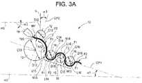
- FIG. 3Ais a schematic side view of a portion of a polymer film casting apparatus of the present invention.
- FIG. 3Bis a schematic side view of a portion of a polymer film casting apparatus of the present invention having an air impingement device;
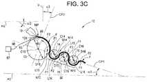
- FIG. 3Cis a schematic side view of a portion of a polymer film casting apparatus of the present invention having a vacuum device;
- FIG. 4is a side view of the polymer film casting apparatus of FIG. 3A shown installed in a frame in an open configuration;
- FIG. 5is a perspective view of the polymer film casting apparatus of FIG. 4 ;
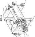
- FIG. 6is a rear perspective view of the polymer film casting apparatus of FIG. 5 .
- a casting apparatus for manufacturing polymer filmis generally designated by the numeral 10 .
- the casting apparatus 10includes a die 19 for discharging a molten polymer MP.
- the die 19is an elongate member that extends in a generally horizontal plane and is in communication with an extruder that supplies the molten polymer MP to the die 19 .
- the die 19has a discharge slit 19 X and is oriented such that the discharge slit 19 X has a discharge direction oriented at a non-zero discharge angle ⁇ 2 that is offset from a first horizontal reference plane H 1 .
- the non-zero discharge angle ⁇ 2is from 10 to 45 degrees.
- the non-zero discharge angle ⁇ 2 of the discharge direction of the die 19is of a predetermined magnitude to gravity assist delivery of the molten polymer MP to the first gap N 12 .
- the discharge directionpoints downwardly at the non-zero discharge angle ⁇ 2 to allow the force of gravity to urge the molten polymer into the gap N 12 for sizing.
- employing the non-zero discharge angle ⁇ 2mitigates or eliminates the problems of the prior art polymer film casting devices, such as sagging of the molten polymer that can cause flutter, and intermittent and premature contact of the molten polymer with the chill roll 12 , before sizing.
- the present inventionis not limited in this regard as the first chill roll 12 may be eliminated and replaced with an film displacement device 55 (e.g., a vessel or box) that has an elongate discharge slit 56 therein.
- the second chill roll 13 and the film displacement device 55are positioned downstream of the die 19 .
- the die 19 and orientation thereof shown in FIG. 3Bare configured similar to the die 19 shown in FIG. 3A .
- the film displacement device 55 of FIG. 3Bis shown and described as being the fluid impingement device (e.g., an air knife) that is in communication with the fluid supply source 57 (e.g., air compressor, air tank, nitrogen supply, liquid supply or pump) via the suitable conduit 58 , the present invention is not limited in this regard as other configurations may be employed.
- the first chill roll 12may be eliminated and replaced with a film displacement device 65 (e.g., a vessel or box) that has an elongate discharge slit 66 therein.
- the second chill roll 13 and the film displacement device 65are positioned downstream of the die 19 .
- the die 19 and orientation thereof shown in FIG. 3Care configured similar to the die 19 shown in FIG.
- the polishing stage 30includes a third polishing roll 16 positioned downstream of the second polishing roll 15 .
- a fourth gap N 15(e.g., a nip, adjustable during operation of the casting apparatus 10 ) is located between the second polishing roll 15 and the third polishing roll 16 .
- the first polishing roll 14 , the second polishing roll 15 and the third polishing roll 16are rotatably mounted to the frame 20 , about respective center lines C 14 , C 15 and C 16 , by respective bracket and bearing assemblies 14 B, 15 B and 16 B.
- the first polishing roll 14 , the second polishing roll 15 and the third polishing roll 16are moveably mounted to the frame 20 to allow of adjustment of the position thereof relative to each other and the second chill roll 13 .
- the movability of the first polishing roll 14 , the second polishing roll 15 and the third polishing roll 16allows for adjustment of the size of the gaps N 13 , N 14 and N 15 to create respective nips at each gap N 13 , N 14 and N 15 for controlling the thickness of the polymer film F, during operation of the casting apparatus 10 .
- the first polishing roll 14engages and cools a second length L 14 of a second side F 2 of the polymer film F.
- the second side F 2is opposite the first side F 1 .
- the first length L 13is substantially equal to the second length L 14 .
- the first length L 13extends along an exterior surface of the second chill roll 13 , between the first gap N 12 and the second gap N 13 .
- the second length L 14extends along an exterior surface of the first polishing roll 14 , between the second gap N 13 and the third gap N 14 .
- the first side F 1 of the polymer film Fengages and extends a third length L 15 on an exterior surface of the second polishing roll 15 , between the third gap N 14 and the fourth gap N 15 .
- the second side F 2 of the polymer film Fengages and extends a fourth length L 16 on an exterior surface of the third polishing roll 16 between the fourth gap N 15 and a line located opposite the fourth gap N 15 (e.g., about 180 degrees around the third polishing roll 16 ).
- the location of the line located opposite the fourth gap N 15is determined by the angle of discharge of the polymer film F from the third polishing roll 16 .
- the first length L 13is established by the second diameter D 13 of the second chill roll 13 .
- the second length L 14is established by the third diameter D 14 of the first polishing roll 14 .
- the third length L 15is established by a fourth diameter D 15 of the second polishing roll 15 .
- the fourth length L 16is established by the fifth diameter D 16 of the third polishing roll 16 .
Landscapes
- Engineering & Computer Science (AREA)
- Mechanical Engineering (AREA)
- Physics & Mathematics (AREA)
- Thermal Sciences (AREA)
- Extrusion Moulding Of Plastics Or The Like (AREA)
Abstract
Description
Claims (35)
Priority Applications (1)
| Application Number | Priority Date | Filing Date | Title |
|---|---|---|---|
| US16/937,655US11167465B2 (en) | 2017-09-26 | 2020-07-24 | Casting apparatus for manufacturing polymer film |
Applications Claiming Priority (3)
| Application Number | Priority Date | Filing Date | Title |
|---|---|---|---|
| US201762563411P | 2017-09-26 | 2017-09-26 | |
| US16/141,279US11173644B2 (en) | 2017-09-26 | 2018-09-25 | Casting apparatus for manufacturing polymer film |
| US16/937,655US11167465B2 (en) | 2017-09-26 | 2020-07-24 | Casting apparatus for manufacturing polymer film |
Related Parent Applications (1)
| Application Number | Title | Priority Date | Filing Date |
|---|---|---|---|
| US16/141,279DivisionUS11173644B2 (en) | 2017-09-26 | 2018-09-25 | Casting apparatus for manufacturing polymer film |
Publications (2)
| Publication Number | Publication Date |
|---|---|
| US20200353664A1 US20200353664A1 (en) | 2020-11-12 |
| US11167465B2true US11167465B2 (en) | 2021-11-09 |
Family
ID=65807093
Family Applications (2)
| Application Number | Title | Priority Date | Filing Date |
|---|---|---|---|
| US16/141,279Active2039-03-12US11173644B2 (en) | 2017-09-26 | 2018-09-25 | Casting apparatus for manufacturing polymer film |
| US16/937,655ActiveUS11167465B2 (en) | 2017-09-26 | 2020-07-24 | Casting apparatus for manufacturing polymer film |
Family Applications Before (1)
| Application Number | Title | Priority Date | Filing Date |
|---|---|---|---|
| US16/141,279Active2039-03-12US11173644B2 (en) | 2017-09-26 | 2018-09-25 | Casting apparatus for manufacturing polymer film |
Country Status (3)
| Country | Link |
|---|---|
| US (2) | US11173644B2 (en) |
| CA (1) | CA3018516A1 (en) |
| MX (2) | MX2018011707A (en) |
Families Citing this family (1)
| Publication number | Priority date | Publication date | Assignee | Title |
|---|---|---|---|---|
| US11667061B2 (en)* | 2020-04-18 | 2023-06-06 | Rohm And Haas Electronic Materials Cmp Holdings, Inc. | Method of forming leveraged poromeric polishing pad |
Citations (101)
| Publication number | Priority date | Publication date | Assignee | Title |
|---|---|---|---|---|
| DE1957708A1 (en) | 1969-11-17 | 1971-05-19 | Bellaplast Maschinen Verkaufs | Temperature control device for extruded thermoplastic films |
| US3581340A (en) | 1967-11-30 | 1971-06-01 | Schloemann Ag | Calenders,particularly in drawing calenders for the production of webs of foil or film |
| GB1316758A (en) | 1969-06-10 | 1973-05-16 | Berstorff Gmbh Masch Hermann | Calendering |
| GB1318274A (en) | 1969-06-10 | 1973-05-23 | Berstorff Gmbh Masch Hermann | Method of continuously compacting heating kneading and mixing plasticisable material |
| GB1371085A (en) | 1971-01-14 | 1974-10-23 | Berstorff Gmbh Masch Hermann | Calender for plastics material |
| GB1394790A (en) | 1973-01-08 | 1975-05-21 | Berstorff Gmbh Masch Hermann | Calenders |
| GB1424499A (en) | 1973-08-23 | 1976-02-11 | Berstorff Gmbh Masch Hermann | Method of and apparatus for the draw-in of powdered material into a roller gap |
| US3964848A (en) | 1973-09-15 | 1976-06-22 | Hermann Berstorff Maschinenbau Gmbh | Calendering of synthetic plastics film |
| GB1465648A (en) | 1973-08-23 | 1977-02-23 | Berstorff Gmbh Masch Hermann | Method of and apparatus for the draw-in of powdered material |
| US4014636A (en) | 1974-12-21 | 1977-03-29 | Hermann Berstorff Maschinenbau Gmbh | Synthetic plastics film manufacturing plant including a multiple-roll calender |
| US4038012A (en) | 1974-08-14 | 1977-07-26 | Hermann Berstorff Maschinenbau Gmbh | Multiple-roll calendars for producing thermoplastics film |
| US4056592A (en) | 1974-07-11 | 1977-11-01 | Dai Nippon Toryo Co., Ltd. | Process for preparation of thermosetting resin powder paints |
| US4066729A (en) | 1969-06-04 | 1978-01-03 | Agfa-Gevaert, N.V. | Extrusion method and apparatus |
| US4105386A (en) | 1973-10-19 | 1978-08-08 | Bellaplast Gmbh | Apparatus for the manufacture of thin-walled shaped articles of thermoplastic material |
| US4110387A (en) | 1975-10-01 | 1978-08-29 | Hermann Berstorff Maschinenbau Gmbh | Method of controlling operation of a multi-roll calender |
| US4311658A (en) | 1980-05-02 | 1982-01-19 | Tenneco Chemicals, Inc. | Manufacture of continuous plastic sheets |
| EP0061385A1 (en) | 1981-03-13 | 1982-09-29 | E.M.S. EQUIPEMENTS MECANIQUES SPECIALISES Société Anonyme | Method of regulating the feeding of a calender for plastics material, and apparatus therefor |
| US4408974A (en) | 1982-01-20 | 1983-10-11 | Comerio Ercole, S.P.A. | Mobile film stretching unit |
| DE3229477A1 (en) | 1982-08-06 | 1984-02-09 | Battenfeld-EKK Extrusionstechnik GmbH, 4630 Bochum | Calender especially for the production of plastics films |
| DE3239467A1 (en) | 1982-10-25 | 1984-04-26 | Hermann Berstorff Maschinenbau Gmbh, 3000 Hannover | Process and apparatus for the uniform, surge-free feeding of a roll nip |
| US4477407A (en) | 1982-02-23 | 1984-10-16 | E. I. Du Pont De Nemours And Company | Machine direction orientation of nylon film |
| DE3521331A1 (en) | 1984-07-03 | 1986-01-30 | Barmag Barmer Maschinenfabrik Ag, 5630 Remscheid | Process for producing a high-strength polymer film and device for carrying out the process |
| US4655703A (en) | 1985-02-22 | 1987-04-07 | Hermann Berstorff Maschinenbau Gmbh | Embossing calender for thermoplastics material films |
| US4695239A (en) | 1985-11-14 | 1987-09-22 | Senoplast Klepsch & Co. | Thermoplastic sheet forming device |
| US4734229A (en) | 1984-11-13 | 1988-03-29 | Entek Manufacturing Inc. | Method for calendering temperature-critical thermoplastic material using a two-phase heat transfer medium |
| JPS63197614A (en) | 1987-02-12 | 1988-08-16 | O P C Boeki Kk | Method and apparatus for calender molding |
| EP0325706A2 (en) | 1988-01-23 | 1989-08-02 | HERMANN BERSTORFF Maschinenbau GmbH | Multi-roll coating and laminating calender for the production of composite bands consisting of a plastic or rubber foil of a reinforcing textile band |
| DE3802095A1 (en) | 1988-01-26 | 1989-08-03 | Willi Dipl Ing Hinterkeuser | Apparatus for the uniform, two-sided and shock-like cooling of thermoplastics of a crystalline structure, for example thermoforming sheets and panels of PP, HD-PE etc. |
| EP0335108A2 (en) | 1988-03-30 | 1989-10-04 | Continental Aktiengesellschaft | Device for the production of webbed rubber products |
| EP0466460A2 (en) | 1990-07-11 | 1992-01-15 | Minnesota Mining And Manufacturing Company | Method of making a flexible louvered plastic film |
| US5087191A (en) | 1990-01-17 | 1992-02-11 | Hermann Berstorff Maschinenbau Gmbh | Embossing calender assembly |
| JPH05253962A (en) | 1992-03-16 | 1993-10-05 | Tsutsunaka Plast Ind Co Ltd | Production of thermoplastic resin sheet |
| US5262101A (en) | 1989-11-21 | 1993-11-16 | Toshiba Kikai Kabushiki Kaisha | Bank quantity monitoring method and apparatus, sheet forming method and apparatus, and sheet temperature measuring method and apparatus |
| JPH05309679A (en) | 1992-05-13 | 1993-11-22 | Nitto Boseki Co Ltd | Method and apparatus for manufacturing short fiber reinforced thermoplastic resin sheet |
| US5397526A (en) | 1989-09-05 | 1995-03-14 | Hpm Corporation | Method for reconfiguring finishing rolls in a plastic sheet fabrication sheetline |
| US5423671A (en) | 1988-11-16 | 1995-06-13 | Canon Kabushiki Kaisha | Apparatus for producing a substrate sheet for an optical recording medium |
| US5425959A (en) | 1991-07-31 | 1995-06-20 | Buehler Ag | Process of and apparatus for pressing and drying long pasta |
| US5464363A (en) | 1993-02-18 | 1995-11-07 | Hermann Berstorff Maschinenbau Gmbh | Polishing stack for thermoplastic films or sheets |
| US5466403A (en) | 1994-05-31 | 1995-11-14 | Welex Incorporated | Apparatus and method for extruding and cooling a polymeric sheet |
| JPH08230018A (en) | 1995-02-27 | 1996-09-10 | Hitachi Zosen Sangyo Kk | Production equipment of thermoplastic synthetic resin sheet-like formed article |
| WO1996038287A1 (en) | 1995-05-29 | 1996-12-05 | Hoechst Aktiengesellschaft | Amorphous dyed plate of a crystallisable thermoplastic |
| EP0759350A1 (en) | 1995-08-11 | 1997-02-26 | Nan Ya Plastics Corporation | Improved calender system |
| DE19544988A1 (en) | 1995-12-02 | 1997-06-05 | Anton Breyer Ohg | Calendar roller smoothing and adjusting thickness of plastic sheet |
| JPH09155951A (en) | 1995-12-01 | 1997-06-17 | Sekisui Chem Co Ltd | Manufacture of polysulphone resin film |
| WO1997034759A2 (en) | 1996-03-20 | 1997-09-25 | Hoechst Research & Technology Deutschland Gmbh & Co. Kg | Amorphous plate of a crystallizable polyalkylene naphthalate |
| US5695698A (en) | 1996-01-30 | 1997-12-09 | Ajji; Abdellah | Production of oriented plastics by roll-drawing |
| DE29722223U1 (en) | 1997-12-16 | 1998-02-26 | Battenfeld Extrusionstechnik Gmbh, 32547 Bad Oeynhausen | Successor device for a calender for producing a composite plastic film |
| JP2781836B2 (en) | 1989-10-16 | 1998-07-30 | 石川島播磨重工業株式会社 | Five roll calendar and calendar device |
| WO1998050222A1 (en) | 1997-05-02 | 1998-11-12 | Aventis Research & Technologies Gmbh & Co. Kg | Amorphous plate with a structured surface |
| US5868983A (en) | 1996-10-30 | 1999-02-09 | Bayer Aktiengesellschaft | Surface finishing of sheets made from thermoplastics |
| US5885522A (en) | 1996-09-12 | 1999-03-23 | Midland Steel Products Co. | Method and apparatus for heat treating and straightening structural members |
| US5912026A (en) | 1997-08-25 | 1999-06-15 | Preferred Plastic Sheet Company | Device for providing a hinge to extruded plastic |
| JP2000043071A (en) | 1998-07-28 | 2000-02-15 | Ishikawajima Harima Heavy Ind Co Ltd | Seven-roll calender and roll forming method |
| US6045349A (en) | 1995-12-07 | 2000-04-04 | Nippon Petrochemicals Company Limited | Rolling apparatus for plastic film |
| US6071110A (en) | 1997-09-11 | 2000-06-06 | Mikkelsen; Oeystein | Polishing roll and method for making same |
| US6187422B1 (en) | 1995-05-29 | 2001-02-13 | Hostaglas Ltd | Amorphous transparent plate made of crystallizable thermoplastic materials |
| US6250904B1 (en) | 1999-02-22 | 2001-06-26 | General Electric Company | Closed loop control of roll speeds in plastic sheet extrusion |
| US6254712B1 (en) | 1998-12-08 | 2001-07-03 | Avery Dennison Corporation | Extrusion coating process for making high transparency protective and decorative films |
| DE19961743A1 (en) | 1999-12-21 | 2001-07-12 | Battenfeld Extrusionstech | In-line extrusion and fabrication of plastic film, e.g. for containers, involves controlling the extrusion speed to suit the fabrication process |
| JP3227897B2 (en) | 1993-04-07 | 2001-11-12 | 石川島播磨重工業株式会社 | calendar |
| JP3250578B2 (en) | 1993-01-05 | 2002-01-28 | 石川島播磨重工業株式会社 | 6 roll calendar |
| US6403005B1 (en) | 2000-04-04 | 2002-06-11 | Avery Dennison Corporation | Method of manufacturing a high doi/high gloss multifunctional thermoplastic film |
| US6406285B1 (en) | 1999-10-21 | 2002-06-18 | Welex Incorporated | Apparatus for measuring and of controlling the gap between polymer sheet cooling rolls |
| US20020074691A1 (en) | 1999-09-14 | 2002-06-20 | Robert M Mortellite | High speed method of making plastic film and nonwoven laminates |
| JP2002347052A (en) | 2001-05-28 | 2002-12-04 | Bando Chem Ind Ltd | Resin sheet having a straight-grain pattern, method of manufacturing the same, and manufacturing apparatus |
| US6575726B1 (en)* | 2000-09-06 | 2003-06-10 | Welex Incorporated | Apparatus for cooling an extruded plastic sheet |
| JP2003236869A (en) | 2002-02-19 | 2003-08-26 | Nitto Denko Corp | Calender roll device |
| JP2004050690A (en) | 2002-07-22 | 2004-02-19 | Toshiba Mach Co Ltd | Film casting equipment |
| US20040104496A1 (en) | 2002-11-25 | 2004-06-03 | Fuji Photo Film Co., Ltd. | Solution casting process for producing polymer film |
| US6773649B2 (en) | 2001-02-16 | 2004-08-10 | General Electric Company | Film extrusion process for producing thermoplastic film |
| WO2004096894A2 (en) | 2003-04-26 | 2004-11-11 | Merck Patent Gmbh | Moulded article containing cladded core particles |
| US6913714B2 (en) | 2002-11-21 | 2005-07-05 | Bayer Materialscience Llc | Method of producing thermoplastic polycarbonate films having low optical retardation values |
| EP1600277A2 (en) | 2004-05-27 | 2005-11-30 | Battenfeld Extrusionstechnik GmbH | Cooling Device |
| US6991758B2 (en) | 2001-09-05 | 2006-01-31 | Reifenhauser Gmbh & Co. Maschinenfabrik | Method of making a web having good breathing properties |
| US20060131779A1 (en) | 2002-11-26 | 2006-06-22 | Seiji Kagawa | Method for producing polybutylene terephthalate film |
| DE102005006412A1 (en) | 2004-09-14 | 2006-08-10 | Helmut Vaic | Cold-spray tick pincers for freezing, killing and removal of ticks, are manufactured in a single work step or injection molding process |
| US20060244174A1 (en) | 2005-04-29 | 2006-11-02 | Panterra Engineered Plastics, Inc. | Advanced method and apparatus for cost-effectively and continuously producing expanded thermoformable honeycomb materials |
| JP3846566B2 (en) | 2002-02-20 | 2006-11-15 | 日本ゼオン株式会社 | Method for producing thermoplastic resin sheet |
| US20060260484A1 (en)* | 2005-05-23 | 2006-11-23 | Koji Mizunuma | Sheet forming apparatus and roller gap control method |
| US7165962B2 (en) | 2004-12-21 | 2007-01-23 | Hanson Dana R | Web handling roll stand |
| DE102006012417A1 (en) | 2006-03-17 | 2007-09-20 | Kuhne Gmbh | Device for the section-wise regulation of material foil temperature in foil manufacturing plant, comprises storage device with two guide roller elements whose distance relatively alterable to each other, measuring device and control device |
| US20070267773A1 (en) | 2006-04-19 | 2007-11-22 | Takehisa Kishimoto | Process for producing thermoplastic resin sheet with controlled warpage |
| US20080034986A1 (en) | 2004-07-08 | 2008-02-14 | Bernhard Lucas | Method for Operating a Four-Roll Calendar Machine |
| JP2008056890A (en) | 2006-05-30 | 2008-03-13 | Fujifilm Corp | Cellulose acylate composition, cellulose acylate film and method for producing the same, polarizing plate, optical compensation film, antireflection film, and liquid crystal display device |
| US7442332B2 (en) | 2004-05-04 | 2008-10-28 | Clopay Plastic Products Company, Inc. | Method and apparatus for uniformly stretching thermoplastic film and products produced thereby |
| JP4183336B2 (en) | 1999-05-27 | 2008-11-19 | 株式会社浅野研究所 | Chill roll apparatus, resin sheet manufacturing apparatus, and resin sheet manufacturing method |
| US20090169772A1 (en) | 2005-12-09 | 2009-07-02 | Konica Minolta Opto, Inc. | Retardation film, method for producing retardation film, polarizing plate and liquid crystal display |
| US20090261500A1 (en) | 2005-11-22 | 2009-10-22 | Fujifilm Corporation | Method for manufacturing cellulose resin film |
| JP4396698B2 (en) | 2005-12-14 | 2010-01-13 | 住友化学株式会社 | Method for producing extruded resin plate |
| WO2010035900A1 (en) | 2008-09-26 | 2010-04-01 | 住友化学株式会社 | Method for producing crystalline resin sheet |
| US20100109180A1 (en) | 2008-11-06 | 2010-05-06 | Klaus Becker | Process for cooling flat plastic products |
| US7803292B2 (en) | 2005-12-28 | 2010-09-28 | Konica Minolta Opto, Inc. | Optical film, optical film manufacturing method and optical film manufacturing device |
| EP1424184B1 (en) | 2002-11-28 | 2011-01-05 | Comerio Ercole S.p.A. | Device for the inserting and removing rollers in a calender assembly |
| US20110201746A1 (en) | 2008-10-02 | 2011-08-18 | Nitto Denko Corporation | Polylactic acid-based film or sheet |
| WO2011129259A1 (en) | 2010-04-13 | 2011-10-20 | 株式会社Ihi | Induction heating roll device |
| WO2011129257A1 (en) | 2010-04-13 | 2011-10-20 | 株式会社Ihi | Calender |
| EP2431153A2 (en) | 2010-09-17 | 2012-03-21 | battenfeld-cincinnati Germany GmbH | Method for inline control for film assemblies |
| DE102011003604A1 (en) | 2011-02-03 | 2012-08-09 | Battenfeld-Cincinnati Germany Gmbh | Cooling device and cooling method |
| WO2012133196A1 (en) | 2011-03-31 | 2012-10-04 | 東レ株式会社 | Process for producing solar cell sealing sheet |
| CN105598334A (en) | 2016-02-18 | 2016-05-25 | 南通皋液液压机有限公司 | Hydraulic system for hydraulic machine for forging and pressing elastic materials |
| CN205763584U (en) | 2016-02-18 | 2016-12-07 | 南通皋液液压机有限公司 | A kind of hydraulic system of the hydraulic press forging and pressing elastomeric material |
- 2018
- 2018-09-25CACA3018516Apatent/CA3018516A1/enactivePending
- 2018-09-25USUS16/141,279patent/US11173644B2/enactiveActive
- 2018-09-26MXMX2018011707Apatent/MX2018011707A/enunknown
- 2018-09-26MXMX2022013102Apatent/MX2022013102A/enunknown
- 2020
- 2020-07-24USUS16/937,655patent/US11167465B2/enactiveActive
Patent Citations (111)
| Publication number | Priority date | Publication date | Assignee | Title |
|---|---|---|---|---|
| US3581340A (en) | 1967-11-30 | 1971-06-01 | Schloemann Ag | Calenders,particularly in drawing calenders for the production of webs of foil or film |
| US4066729A (en) | 1969-06-04 | 1978-01-03 | Agfa-Gevaert, N.V. | Extrusion method and apparatus |
| GB1316758A (en) | 1969-06-10 | 1973-05-16 | Berstorff Gmbh Masch Hermann | Calendering |
| GB1318274A (en) | 1969-06-10 | 1973-05-23 | Berstorff Gmbh Masch Hermann | Method of continuously compacting heating kneading and mixing plasticisable material |
| DE1957708A1 (en) | 1969-11-17 | 1971-05-19 | Bellaplast Maschinen Verkaufs | Temperature control device for extruded thermoplastic films |
| GB1371085A (en) | 1971-01-14 | 1974-10-23 | Berstorff Gmbh Masch Hermann | Calender for plastics material |
| GB1394790A (en) | 1973-01-08 | 1975-05-21 | Berstorff Gmbh Masch Hermann | Calenders |
| GB1424499A (en) | 1973-08-23 | 1976-02-11 | Berstorff Gmbh Masch Hermann | Method of and apparatus for the draw-in of powdered material into a roller gap |
| GB1465648A (en) | 1973-08-23 | 1977-02-23 | Berstorff Gmbh Masch Hermann | Method of and apparatus for the draw-in of powdered material |
| US3964848A (en) | 1973-09-15 | 1976-06-22 | Hermann Berstorff Maschinenbau Gmbh | Calendering of synthetic plastics film |
| US4105386A (en) | 1973-10-19 | 1978-08-08 | Bellaplast Gmbh | Apparatus for the manufacture of thin-walled shaped articles of thermoplastic material |
| US4056592A (en) | 1974-07-11 | 1977-11-01 | Dai Nippon Toryo Co., Ltd. | Process for preparation of thermosetting resin powder paints |
| US4038012A (en) | 1974-08-14 | 1977-07-26 | Hermann Berstorff Maschinenbau Gmbh | Multiple-roll calendars for producing thermoplastics film |
| US4014636A (en) | 1974-12-21 | 1977-03-29 | Hermann Berstorff Maschinenbau Gmbh | Synthetic plastics film manufacturing plant including a multiple-roll calender |
| US4110387A (en) | 1975-10-01 | 1978-08-29 | Hermann Berstorff Maschinenbau Gmbh | Method of controlling operation of a multi-roll calender |
| US4214857A (en) | 1975-10-01 | 1980-07-29 | Hermann Berstorff Maschinenbau Gmbh | Multi-roll calender |
| US4311658A (en) | 1980-05-02 | 1982-01-19 | Tenneco Chemicals, Inc. | Manufacture of continuous plastic sheets |
| EP0061385A1 (en) | 1981-03-13 | 1982-09-29 | E.M.S. EQUIPEMENTS MECANIQUES SPECIALISES Société Anonyme | Method of regulating the feeding of a calender for plastics material, and apparatus therefor |
| US4408974A (en) | 1982-01-20 | 1983-10-11 | Comerio Ercole, S.P.A. | Mobile film stretching unit |
| US4477407A (en) | 1982-02-23 | 1984-10-16 | E. I. Du Pont De Nemours And Company | Machine direction orientation of nylon film |
| DE3229477A1 (en) | 1982-08-06 | 1984-02-09 | Battenfeld-EKK Extrusionstechnik GmbH, 4630 Bochum | Calender especially for the production of plastics films |
| DE3239467A1 (en) | 1982-10-25 | 1984-04-26 | Hermann Berstorff Maschinenbau Gmbh, 3000 Hannover | Process and apparatus for the uniform, surge-free feeding of a roll nip |
| DE3521331A1 (en) | 1984-07-03 | 1986-01-30 | Barmag Barmer Maschinenfabrik Ag, 5630 Remscheid | Process for producing a high-strength polymer film and device for carrying out the process |
| US4734229A (en) | 1984-11-13 | 1988-03-29 | Entek Manufacturing Inc. | Method for calendering temperature-critical thermoplastic material using a two-phase heat transfer medium |
| US4655703A (en) | 1985-02-22 | 1987-04-07 | Hermann Berstorff Maschinenbau Gmbh | Embossing calender for thermoplastics material films |
| US4695239A (en) | 1985-11-14 | 1987-09-22 | Senoplast Klepsch & Co. | Thermoplastic sheet forming device |
| JPS63197614A (en) | 1987-02-12 | 1988-08-16 | O P C Boeki Kk | Method and apparatus for calender molding |
| EP0325706A2 (en) | 1988-01-23 | 1989-08-02 | HERMANN BERSTORFF Maschinenbau GmbH | Multi-roll coating and laminating calender for the production of composite bands consisting of a plastic or rubber foil of a reinforcing textile band |
| DE3802095A1 (en) | 1988-01-26 | 1989-08-03 | Willi Dipl Ing Hinterkeuser | Apparatus for the uniform, two-sided and shock-like cooling of thermoplastics of a crystalline structure, for example thermoforming sheets and panels of PP, HD-PE etc. |
| EP0335108A2 (en) | 1988-03-30 | 1989-10-04 | Continental Aktiengesellschaft | Device for the production of webbed rubber products |
| US5423671A (en) | 1988-11-16 | 1995-06-13 | Canon Kabushiki Kaisha | Apparatus for producing a substrate sheet for an optical recording medium |
| US5397526A (en) | 1989-09-05 | 1995-03-14 | Hpm Corporation | Method for reconfiguring finishing rolls in a plastic sheet fabrication sheetline |
| JP2781836B2 (en) | 1989-10-16 | 1998-07-30 | 石川島播磨重工業株式会社 | Five roll calendar and calendar device |
| US5262101A (en) | 1989-11-21 | 1993-11-16 | Toshiba Kikai Kabushiki Kaisha | Bank quantity monitoring method and apparatus, sheet forming method and apparatus, and sheet temperature measuring method and apparatus |
| US5087191A (en) | 1990-01-17 | 1992-02-11 | Hermann Berstorff Maschinenbau Gmbh | Embossing calender assembly |
| EP0466460A2 (en) | 1990-07-11 | 1992-01-15 | Minnesota Mining And Manufacturing Company | Method of making a flexible louvered plastic film |
| US5425959A (en) | 1991-07-31 | 1995-06-20 | Buehler Ag | Process of and apparatus for pressing and drying long pasta |
| JPH05253962A (en) | 1992-03-16 | 1993-10-05 | Tsutsunaka Plast Ind Co Ltd | Production of thermoplastic resin sheet |
| JPH05309679A (en) | 1992-05-13 | 1993-11-22 | Nitto Boseki Co Ltd | Method and apparatus for manufacturing short fiber reinforced thermoplastic resin sheet |
| JP3250578B2 (en) | 1993-01-05 | 2002-01-28 | 石川島播磨重工業株式会社 | 6 roll calendar |
| US5464363A (en) | 1993-02-18 | 1995-11-07 | Hermann Berstorff Maschinenbau Gmbh | Polishing stack for thermoplastic films or sheets |
| JP3227897B2 (en) | 1993-04-07 | 2001-11-12 | 石川島播磨重工業株式会社 | calendar |
| US5466403A (en) | 1994-05-31 | 1995-11-14 | Welex Incorporated | Apparatus and method for extruding and cooling a polymeric sheet |
| JPH08230018A (en) | 1995-02-27 | 1996-09-10 | Hitachi Zosen Sangyo Kk | Production equipment of thermoplastic synthetic resin sheet-like formed article |
| WO1996038287A1 (en) | 1995-05-29 | 1996-12-05 | Hoechst Aktiengesellschaft | Amorphous dyed plate of a crystallisable thermoplastic |
| US6187422B1 (en) | 1995-05-29 | 2001-02-13 | Hostaglas Ltd | Amorphous transparent plate made of crystallizable thermoplastic materials |
| EP0759350A1 (en) | 1995-08-11 | 1997-02-26 | Nan Ya Plastics Corporation | Improved calender system |
| JPH09155951A (en) | 1995-12-01 | 1997-06-17 | Sekisui Chem Co Ltd | Manufacture of polysulphone resin film |
| DE19544988A1 (en) | 1995-12-02 | 1997-06-05 | Anton Breyer Ohg | Calendar roller smoothing and adjusting thickness of plastic sheet |
| US6045349A (en) | 1995-12-07 | 2000-04-04 | Nippon Petrochemicals Company Limited | Rolling apparatus for plastic film |
| US5695698A (en) | 1996-01-30 | 1997-12-09 | Ajji; Abdellah | Production of oriented plastics by roll-drawing |
| WO1997034759A2 (en) | 1996-03-20 | 1997-09-25 | Hoechst Research & Technology Deutschland Gmbh & Co. Kg | Amorphous plate of a crystallizable polyalkylene naphthalate |
| WO1997034759A3 (en) | 1996-03-20 | 1997-10-30 | Hoechst Ag | Amorphous plate of a crystallizable polyalkylene naphthalate |
| US5885522A (en) | 1996-09-12 | 1999-03-23 | Midland Steel Products Co. | Method and apparatus for heat treating and straightening structural members |
| US5868983A (en) | 1996-10-30 | 1999-02-09 | Bayer Aktiengesellschaft | Surface finishing of sheets made from thermoplastics |
| WO1998050222A1 (en) | 1997-05-02 | 1998-11-12 | Aventis Research & Technologies Gmbh & Co. Kg | Amorphous plate with a structured surface |
| US5912026A (en) | 1997-08-25 | 1999-06-15 | Preferred Plastic Sheet Company | Device for providing a hinge to extruded plastic |
| US6071110A (en) | 1997-09-11 | 2000-06-06 | Mikkelsen; Oeystein | Polishing roll and method for making same |
| DE29722223U1 (en) | 1997-12-16 | 1998-02-26 | Battenfeld Extrusionstechnik Gmbh, 32547 Bad Oeynhausen | Successor device for a calender for producing a composite plastic film |
| JP2000043071A (en) | 1998-07-28 | 2000-02-15 | Ishikawajima Harima Heavy Ind Co Ltd | Seven-roll calender and roll forming method |
| JP3968879B2 (en) | 1998-07-28 | 2007-08-29 | 石川島播磨重工業株式会社 | 7-roll calender and rolling forming method |
| US6254712B1 (en) | 1998-12-08 | 2001-07-03 | Avery Dennison Corporation | Extrusion coating process for making high transparency protective and decorative films |
| US6250904B1 (en) | 1999-02-22 | 2001-06-26 | General Electric Company | Closed loop control of roll speeds in plastic sheet extrusion |
| JP4183336B2 (en) | 1999-05-27 | 2008-11-19 | 株式会社浅野研究所 | Chill roll apparatus, resin sheet manufacturing apparatus, and resin sheet manufacturing method |
| US20020074691A1 (en) | 1999-09-14 | 2002-06-20 | Robert M Mortellite | High speed method of making plastic film and nonwoven laminates |
| US6406285B1 (en) | 1999-10-21 | 2002-06-18 | Welex Incorporated | Apparatus for measuring and of controlling the gap between polymer sheet cooling rolls |
| DE19961743A1 (en) | 1999-12-21 | 2001-07-12 | Battenfeld Extrusionstech | In-line extrusion and fabrication of plastic film, e.g. for containers, involves controlling the extrusion speed to suit the fabrication process |
| US6403005B1 (en) | 2000-04-04 | 2002-06-11 | Avery Dennison Corporation | Method of manufacturing a high doi/high gloss multifunctional thermoplastic film |
| US6575726B1 (en)* | 2000-09-06 | 2003-06-10 | Welex Incorporated | Apparatus for cooling an extruded plastic sheet |
| US6773649B2 (en) | 2001-02-16 | 2004-08-10 | General Electric Company | Film extrusion process for producing thermoplastic film |
| JP2002347052A (en) | 2001-05-28 | 2002-12-04 | Bando Chem Ind Ltd | Resin sheet having a straight-grain pattern, method of manufacturing the same, and manufacturing apparatus |
| US6991758B2 (en) | 2001-09-05 | 2006-01-31 | Reifenhauser Gmbh & Co. Maschinenfabrik | Method of making a web having good breathing properties |
| JP2003236869A (en) | 2002-02-19 | 2003-08-26 | Nitto Denko Corp | Calender roll device |
| JP3846566B2 (en) | 2002-02-20 | 2006-11-15 | 日本ゼオン株式会社 | Method for producing thermoplastic resin sheet |
| JP2004050690A (en) | 2002-07-22 | 2004-02-19 | Toshiba Mach Co Ltd | Film casting equipment |
| US6913714B2 (en) | 2002-11-21 | 2005-07-05 | Bayer Materialscience Llc | Method of producing thermoplastic polycarbonate films having low optical retardation values |
| US20040104496A1 (en) | 2002-11-25 | 2004-06-03 | Fuji Photo Film Co., Ltd. | Solution casting process for producing polymer film |
| US20060131779A1 (en) | 2002-11-26 | 2006-06-22 | Seiji Kagawa | Method for producing polybutylene terephthalate film |
| EP1424184B1 (en) | 2002-11-28 | 2011-01-05 | Comerio Ercole S.p.A. | Device for the inserting and removing rollers in a calender assembly |
| WO2004096894A2 (en) | 2003-04-26 | 2004-11-11 | Merck Patent Gmbh | Moulded article containing cladded core particles |
| US7442332B2 (en) | 2004-05-04 | 2008-10-28 | Clopay Plastic Products Company, Inc. | Method and apparatus for uniformly stretching thermoplastic film and products produced thereby |
| US20050263939A1 (en) | 2004-05-27 | 2005-12-01 | Nikolaus Krampf | Cooling device |
| EP1600277A2 (en) | 2004-05-27 | 2005-11-30 | Battenfeld Extrusionstechnik GmbH | Cooling Device |
| US20080034986A1 (en) | 2004-07-08 | 2008-02-14 | Bernhard Lucas | Method for Operating a Four-Roll Calendar Machine |
| DE102005006412A1 (en) | 2004-09-14 | 2006-08-10 | Helmut Vaic | Cold-spray tick pincers for freezing, killing and removal of ticks, are manufactured in a single work step or injection molding process |
| US7165962B2 (en) | 2004-12-21 | 2007-01-23 | Hanson Dana R | Web handling roll stand |
| US20060244174A1 (en) | 2005-04-29 | 2006-11-02 | Panterra Engineered Plastics, Inc. | Advanced method and apparatus for cost-effectively and continuously producing expanded thermoformable honeycomb materials |
| US20060260484A1 (en)* | 2005-05-23 | 2006-11-23 | Koji Mizunuma | Sheet forming apparatus and roller gap control method |
| US20090261500A1 (en) | 2005-11-22 | 2009-10-22 | Fujifilm Corporation | Method for manufacturing cellulose resin film |
| US20090169772A1 (en) | 2005-12-09 | 2009-07-02 | Konica Minolta Opto, Inc. | Retardation film, method for producing retardation film, polarizing plate and liquid crystal display |
| JP4396698B2 (en) | 2005-12-14 | 2010-01-13 | 住友化学株式会社 | Method for producing extruded resin plate |
| US7803292B2 (en) | 2005-12-28 | 2010-09-28 | Konica Minolta Opto, Inc. | Optical film, optical film manufacturing method and optical film manufacturing device |
| DE102006012417A1 (en) | 2006-03-17 | 2007-09-20 | Kuhne Gmbh | Device for the section-wise regulation of material foil temperature in foil manufacturing plant, comprises storage device with two guide roller elements whose distance relatively alterable to each other, measuring device and control device |
| US20070267773A1 (en) | 2006-04-19 | 2007-11-22 | Takehisa Kishimoto | Process for producing thermoplastic resin sheet with controlled warpage |
| JP2008056890A (en) | 2006-05-30 | 2008-03-13 | Fujifilm Corp | Cellulose acylate composition, cellulose acylate film and method for producing the same, polarizing plate, optical compensation film, antireflection film, and liquid crystal display device |
| WO2010035900A1 (en) | 2008-09-26 | 2010-04-01 | 住友化学株式会社 | Method for producing crystalline resin sheet |
| US20110201746A1 (en) | 2008-10-02 | 2011-08-18 | Nitto Denko Corporation | Polylactic acid-based film or sheet |
| EP2184156A2 (en) | 2008-11-06 | 2010-05-12 | Battenfeld Extrusionstechnik GmbH | Process for cooling flat plastic products |
| US20100109180A1 (en) | 2008-11-06 | 2010-05-06 | Klaus Becker | Process for cooling flat plastic products |
| US8262966B2 (en) | 2008-11-06 | 2012-09-11 | Battenfeld-Cincinnati Germany Gmbh | Process for cooling flat plastic products |
| WO2011129257A1 (en) | 2010-04-13 | 2011-10-20 | 株式会社Ihi | Calender |
| WO2011129259A1 (en) | 2010-04-13 | 2011-10-20 | 株式会社Ihi | Induction heating roll device |
| EP2431153A2 (en) | 2010-09-17 | 2012-03-21 | battenfeld-cincinnati Germany GmbH | Method for inline control for film assemblies |
| DE102011003604A1 (en) | 2011-02-03 | 2012-08-09 | Battenfeld-Cincinnati Germany Gmbh | Cooling device and cooling method |
| CN103347678A (en) | 2011-02-03 | 2013-10-09 | 巴顿菲尔-辛辛那提德国有限公司 | Cooling device and cooling method for extrudate |
| US20130307179A1 (en) | 2011-02-03 | 2013-11-21 | Battenfeld-Cincinnati Germany Gmbh | Cooling device and cooling method for an extrudate |
| US9616606B2 (en) | 2011-02-03 | 2017-04-11 | Battenfeld-Cincinnati Germany Gmbh | Cooling device and cooling method for an extrudate |
| WO2012133196A1 (en) | 2011-03-31 | 2012-10-04 | 東レ株式会社 | Process for producing solar cell sealing sheet |
| CN105598334A (en) | 2016-02-18 | 2016-05-25 | 南通皋液液压机有限公司 | Hydraulic system for hydraulic machine for forging and pressing elastic materials |
| CN205763584U (en) | 2016-02-18 | 2016-12-07 | 南通皋液液压机有限公司 | A kind of hydraulic system of the hydraulic press forging and pressing elastomeric material |
| CN105598334B (en) | 2016-02-18 | 2017-12-01 | 南通皋液重工股份有限公司 | A kind of hydraulic system of elastomeric material forging and stamping |
Non-Patent Citations (9)
| Title |
|---|
| Battenfield-Cincinnati ("Next Generation" extruder series: higher efficiency and more flexibility, press release, Nov. 2016) (Year: 2016).* |
| Gerry Sposato; Multiple All Nipping Rollstands, http://hpmamerica.com/menu-header/innovations/popup/rollsheet.html (last visited May 19, 2009). |
| Intelligent Hydraulics; Fluid Power Journal—Sep./Oct. 2010, pp. 20-21, available at http://fluidpowerjournal.com. |
| Letter from Roger S. Clarke of sample public offer for sale and detailed disclosure of a relevant prior art roll stand, created in 2006. |
| Neal Gigliotti; Plastic Processing—Better gap control improves quality and speed; Hydraulics & Pneumatics, pp. 28-30, (May 2007). |
| Paul R. Lamont; Equipment and Processing Considerations for Thin Gauge PP Sheet; Journal of Plastic Film & Sheeting 14.3: pp. 256-267. Technomic Publ Co Inc. (Jul. 1998). |
| PowerPoint Presentation Publicly given to people of ordinary skill in the art regarding a prior art calendar assembly and details regarding creation and edit dates of the electronic file to establish public disclosure on or before Feb. 1, 2001. |
| Sample Public Offer for Sale dated Mar. 7, 2001 of a relevant prior art polymer sheet system to Compression Polymer Corporation/Scranton Products. |
| Stephen J. Gust; Calendering is still King for High-Volume PVC Sheet; Plastics Engineering: pp. 29-32. (Jan. 1987). |
Also Published As
| Publication number | Publication date |
|---|---|
| US20190091917A1 (en) | 2019-03-28 |
| US20200353664A1 (en) | 2020-11-12 |
| US11173644B2 (en) | 2021-11-16 |
| MX2018011707A (en) | 2019-09-11 |
| MX2022013102A (en) | 2023-01-30 |
| CA3018516A1 (en) | 2019-03-26 |
Similar Documents
| Publication | Publication Date | Title |
|---|---|---|
| US12330364B2 (en) | Device and process to permit monoaxial changes in the length of film webs | |
| US4728277A (en) | Film-handling devices for thin flexible films | |
| CN111479634B (en) | Coating device | |
| US11167465B2 (en) | Casting apparatus for manufacturing polymer film | |
| CN101954734A (en) | The method for thickness regulation of the inflation film that is used to stretch | |
| US5128076A (en) | Apparatus and method for producing an elongate strip of material | |
| US9409340B2 (en) | Method for cooling plastic film tube in blown film process | |
| US5310329A (en) | Air shroud device for a blown film extrusion line | |
| US4846645A (en) | Bubble forming and stabilizing device for use in continuous extrusion process for making a blown film | |
| EP3720823B1 (en) | Method for forming thin glass sheets | |
| KR20150104028A (en) | Labyrinth seal, casting apparatus, solution film forming facility and method | |
| CN105949485B (en) | Solution film-making method and apparatus | |
| US6863517B2 (en) | Apparatus and method for measuring and of controlling the gap between polymer sheet cooling rolls | |
| JP6298419B2 (en) | Die, solution casting method and melt casting method | |
| US6406285B1 (en) | Apparatus for measuring and of controlling the gap between polymer sheet cooling rolls | |
| CA2285404C (en) | Draw-off device for webs of plastic foil tubing | |
| TWI668254B (en) | Solution film forming method and device | |
| CN102372853B (en) | Solution film-forming method and casting apparatus | |
| CN111016124A (en) | Device and method for accurately controlling diameter of film bubble | |
| CN108044857A (en) | Calendering device | |
| JP6265926B2 (en) | Web winding method | |
| KR102151891B1 (en) | Solution film formation method | |
| JP2017065052A (en) | Die, film manufacturing equipment, solution casting method and melt casting method | |
| WO2023176200A1 (en) | Coating device and method for manufacturing web equipped with coating film | |
| KR20120111996A (en) | Solution film forming method |
Legal Events
| Date | Code | Title | Description |
|---|---|---|---|
| FEPP | Fee payment procedure | Free format text:ENTITY STATUS SET TO UNDISCOUNTED (ORIGINAL EVENT CODE: BIG.); ENTITY STATUS OF PATENT OWNER: LARGE ENTITY | |
| AS | Assignment | Owner name:DAVIS-STANDARD, LLC, CONNECTICUT Free format text:ASSIGNMENT OF ASSIGNORS INTEREST;ASSIGNORS:CHRISTIANO, JOHN P.;SMITH, EDWARD J.;MERCKEL, ANDREW A.;SIGNING DATES FROM 20190115 TO 20190326;REEL/FRAME:054949/0960 | |
| STPP | Information on status: patent application and granting procedure in general | Free format text:NON FINAL ACTION MAILED | |
| STPP | Information on status: patent application and granting procedure in general | Free format text:RESPONSE TO NON-FINAL OFFICE ACTION ENTERED AND FORWARDED TO EXAMINER | |
| STPP | Information on status: patent application and granting procedure in general | Free format text:NOTICE OF ALLOWANCE MAILED -- APPLICATION RECEIVED IN OFFICE OF PUBLICATIONS | |
| STPP | Information on status: patent application and granting procedure in general | Free format text:PUBLICATIONS -- ISSUE FEE PAYMENT VERIFIED | |
| STCF | Information on status: patent grant | Free format text:PATENTED CASE | |
| AS | Assignment | Owner name:BANK OF MONTREAL, AS COLLATERAL AGENT, CANADA Free format text:NOTICE OF GRANT OF SECURITY INTEREST IN PATENTS;ASSIGNORS:DAVIS-STANDARD, LLC;THERMOFORMING SYSTEMS, LLC;REEL/FRAME:058495/0515 Effective date:20211210 | |
| AS | Assignment | Owner name:WELLS FARGO BANK, NATIONAL ASSOCIATION, AS COLLATERAL AGENT, TEXAS Free format text:SECURITY INTEREST;ASSIGNOR:DAVIS-STANDARD, LLC;REEL/FRAME:066308/0392 Effective date:20240131 | |
| AS | Assignment | Owner name:THERMOFORMING SYSTEMS, LLC, WASHINGTON Free format text:TERMINATION AND RELEASE OF SECURITY INTEREST IN PATENTS (REEL/FRAME 058495/0515);ASSIGNOR:BANK OF MONTREAL, AS COLLATERAL AGENT;REEL/FRAME:066627/0842 Effective date:20240131 Owner name:DAVIS-STANDARD, LLC, CONNECTICUT Free format text:TERMINATION AND RELEASE OF SECURITY INTEREST IN PATENTS (REEL/FRAME 058495/0515);ASSIGNOR:BANK OF MONTREAL, AS COLLATERAL AGENT;REEL/FRAME:066627/0842 Effective date:20240131 | |
| MAFP | Maintenance fee payment | Free format text:PAYMENT OF MAINTENANCE FEE, 4TH YEAR, LARGE ENTITY (ORIGINAL EVENT CODE: M1551); ENTITY STATUS OF PATENT OWNER: LARGE ENTITY Year of fee payment:4 | |
| AS | Assignment | Owner name:DEUTSCHE BANK AG, NEW YORK BRANCH, AS COLLATERAL AGENT, NEW YORK Free format text:SECURITY INTEREST;ASSIGNOR:DAVIS-STANDARD, LLC;REEL/FRAME:071297/0766 Effective date:20250411 |