US11166719B2 - Endoscopic surgery system consisting of a plurality of staples and an endoscopic applicator - Google Patents
Endoscopic surgery system consisting of a plurality of staples and an endoscopic applicatorDownload PDFInfo
- Publication number
- US11166719B2 US11166719B2US15/549,595US201615549595AUS11166719B2US 11166719 B2US11166719 B2US 11166719B2US 201615549595 AUS201615549595 AUS 201615549595AUS 11166719 B2US11166719 B2US 11166719B2
- Authority
- US
- United States
- Prior art keywords
- staple
- staples
- loader
- endoscopic
- surgery system
- Prior art date
- Legal status (The legal status is an assumption and is not a legal conclusion. Google has not performed a legal analysis and makes no representation as to the accuracy of the status listed.)
- Active, expires
Links
- 238000002674endoscopic surgeryMethods0.000titleclaimsabstractdescription14
- 230000000295complement effectEffects0.000claimsdescription9
- 238000005452bendingMethods0.000abstract1
- 239000000463materialSubstances0.000description2
- 238000000926separation methodMethods0.000description2
- 229910000831SteelInorganic materials0.000description1
- 230000003993interactionEffects0.000description1
- 239000002184metalSubstances0.000description1
- 230000035515penetrationEffects0.000description1
- 230000006641stabilisationEffects0.000description1
- 239000010959steelSubstances0.000description1
- 238000010408sweepingMethods0.000description1
- 210000002105tongueAnatomy0.000description1
- 230000000007visual effectEffects0.000description1
Images


Classifications
- A—HUMAN NECESSITIES
- A61—MEDICAL OR VETERINARY SCIENCE; HYGIENE
- A61B—DIAGNOSIS; SURGERY; IDENTIFICATION
- A61B1/00—Instruments for performing medical examinations of the interior of cavities or tubes of the body by visual or photographical inspection, e.g. endoscopes; Illuminating arrangements therefor
- A61B1/00064—Constructional details of the endoscope body
- A61B1/00071—Insertion part of the endoscope body
- A61B1/0008—Insertion part of the endoscope body characterised by distal tip features
- A—HUMAN NECESSITIES
- A61—MEDICAL OR VETERINARY SCIENCE; HYGIENE
- A61B—DIAGNOSIS; SURGERY; IDENTIFICATION
- A61B17/00—Surgical instruments, devices or methods
- A61B17/064—Surgical staples, i.e. penetrating the tissue
- A61B17/0644—Surgical staples, i.e. penetrating the tissue penetrating the tissue, deformable to closed position
- A—HUMAN NECESSITIES
- A61—MEDICAL OR VETERINARY SCIENCE; HYGIENE
- A61B—DIAGNOSIS; SURGERY; IDENTIFICATION
- A61B17/00—Surgical instruments, devices or methods
- A61B17/068—Surgical staplers, e.g. containing multiple staples or clamps
- A61B17/0682—Surgical staplers, e.g. containing multiple staples or clamps for applying U-shaped staples or clamps, e.g. without a forming anvil
- A61B17/0684—Surgical staplers, e.g. containing multiple staples or clamps for applying U-shaped staples or clamps, e.g. without a forming anvil having a forming anvil staying above the tissue during stapling
- A—HUMAN NECESSITIES
- A61—MEDICAL OR VETERINARY SCIENCE; HYGIENE
- A61B—DIAGNOSIS; SURGERY; IDENTIFICATION
- A61B17/00—Surgical instruments, devices or methods
- A61B17/068—Surgical staplers, e.g. containing multiple staples or clamps
- A61B17/072—Surgical staplers, e.g. containing multiple staples or clamps for applying a row of staples in a single action, e.g. the staples being applied simultaneously
- A61B17/07207—Surgical staplers, e.g. containing multiple staples or clamps for applying a row of staples in a single action, e.g. the staples being applied simultaneously the staples being applied sequentially
- A—HUMAN NECESSITIES
- A61—MEDICAL OR VETERINARY SCIENCE; HYGIENE
- A61B—DIAGNOSIS; SURGERY; IDENTIFICATION
- A61B17/00—Surgical instruments, devices or methods
- A61B17/00234—Surgical instruments, devices or methods for minimally invasive surgery
- A61B2017/00292—Surgical instruments, devices or methods for minimally invasive surgery mounted on or guided by flexible, e.g. catheter-like, means
- A61B2017/00296—Surgical instruments, devices or methods for minimally invasive surgery mounted on or guided by flexible, e.g. catheter-like, means mounted on an endoscope
- A—HUMAN NECESSITIES
- A61—MEDICAL OR VETERINARY SCIENCE; HYGIENE
- A61B—DIAGNOSIS; SURGERY; IDENTIFICATION
- A61B17/00—Surgical instruments, devices or methods
- A61B17/068—Surgical staplers, e.g. containing multiple staples or clamps
- A61B17/072—Surgical staplers, e.g. containing multiple staples or clamps for applying a row of staples in a single action, e.g. the staples being applied simultaneously
- A61B2017/07214—Stapler heads
- A61B2017/07271—Stapler heads characterised by its cartridge
- A—HUMAN NECESSITIES
- A61—MEDICAL OR VETERINARY SCIENCE; HYGIENE
- A61B—DIAGNOSIS; SURGERY; IDENTIFICATION
- A61B17/00—Surgical instruments, devices or methods
- A61B17/068—Surgical staplers, e.g. containing multiple staples or clamps
- A61B17/072—Surgical staplers, e.g. containing multiple staples or clamps for applying a row of staples in a single action, e.g. the staples being applied simultaneously
- A61B2017/07214—Stapler heads
- A61B2017/07278—Stapler heads characterised by its sled or its staple holder
Definitions
- the present inventionrelates to the field of endoscopic staple applicators.
- Such an applicatorenables the surgeons to place staples in order to hold tissues during endoscopic surgery.
- An endoscopic staple applicatoris designed to hold a plurality of staples, in particular ligature staples, in a staple channel and a system of jaws used to apply a staple.
- the jaw systemis connected to the distal end of the staple channel and to the proximal end of a control handle.
- U.S. Pat. No. 8,133,240is known, describing an endoscopic stapling system.
- This systemcomprises deformable staples disposed end to end in a cavity of an interior channel. Runners slide inside this channel under the action of a thrust element. When it is ejected, the staple deforms in order to clamp the body tissue.
- the patent EP 0713684is also known, describing a system formed by a cartridge of staples and a stapling instrument for applying one or more surgical staples to a tissue.
- Each staplehas a body in the rough form of a U comprising a top cross member having adjacent staple lugs on the opposite sides of the top crossmember.
- a cartridge housing receiving a plurality of staplesis arranged in a row so that they have a longitudinal movement through it.
- An anvilis mounted on said housing. The staple furthest forward is moved until it is in contact with said anvil and then tilted from a transverse orientation to a longitudinal orientation, and then deformed by pressure on said anvil in order to fix the staple.
- an endoscopic surgery systemformed firstly by a plurality of staples and secondly by an endoscopic applicator comprising a staple loader disposed transversely, characterised in that said staples have a central zone and two lateral arms and in that the applicator comprises a movable member having a means for holding, in a transverse frame, a staple to be applied and for ensuring deformation thereof by folding with respect to the symmetry axis of said staple.
- the control memberis formed by a rigid hollow tubular sleeve and a rigid rod sliding longitudinally inside this sleeve, having a guide channel with a complementary cross section.
- said rigid rodhas a polygonal cross section complementary to the cross section of said guide channel provided in the sleeve.
- said rodhas, at its distal end, a bevel defining a surface inclined with respect to a longitudinal plane, ending at a stub extending perpendicular to the longitudinal axis.
- said applicatorcomprises a loader able to be mounted on the distal end of an endoscope.
- said applicatorcomprises a dorsal part defining a reception surface, the cross section of which corresponds to the cross section defined by the interior edges of the two arms of a staple, the loader further comprising an arch engaged on this dorsal part and guided by two lateral flutes.
- the stapleis in the general form of a horseshoe.
- the staplehas two arms connected by a connecting zone, the distal surface of which has a shape complementary to that of the proximal surface of a stub provided at the distal end of a rod able to move with respect to a sleeve.
- the inventionalso relates to an endoscopic applicator comprising a loader for transversely disposed staples, characterised in that it comprises a movable member having a means for holding a staple to be applied, disposed in a transverse plane, and for ensuring deformation thereof by folding with respect to the symmetry axis of said staple, said control member consisting of a rigid hollow tubular sleeve and a rigid rod sliding longitudinally inside this sleeve, having a guide channel with a complementary cross section.
- the applicatorhas a dorsal part defining a reception surface, the cross section of which corresponds to the cross section defined by the interior edges of the two arms of a staple, the loader further comprising an arch engaged on this dorsal part and guided by two lateral flutes.
- the inventionalso relates to a staple for such a system, characterised in that it has two arms connected by a connecting zone, the distal surface of which has a shape complementary to that of the proximal surface of the stabilisation stub.
- FIG. 1shows a view of the control member loaded with a staple
- FIG. 2depicts a view of the staple loader
- FIGS. 3 to 6show views of the applicator at various operating steps.
- the control membercomprises a rigid hollow tubular sleeve ( 1 ).
- a rigid rod ( 2 ) with a polygonal cross sectionslides longitudinally inside this sleeve ( 1 ), having a guide channel with a complementary square cross section.
- This sleeve ( 1 )has at its distal end a bevel ( 3 ) defining a surface inclined with respect to a longitudinal plane, ending in a stub ( 4 ) extending perpendicularly to the longitudinal axis.
- the bevel ( 3 ) and the stub ( 4 )form a zone receiving a staple ( 5 ) having the rough shape of a “horseshoe”.
- the staplehas a roughly semi-annular or “horseshoe” shape, in front view and before stapling.
- the stapleis formed by a steel cutout but it may also be formed by forming a metal wire or from a biodegradable material. It has two arched arms ( 8 , 9 ) extending in a transverse plane perpendicular to the longitudinal axis of the sleeve ( 1 ), symmetrically with respect to a mid-plane ( 6 ) passing through the middle of a connecting portion ( 7 ).
- This mid-plane ( 6 )is defined by an axis parallel to the longitudinal axis of the sleeve ( 1 ) and by the axis of the stub ( 4 ).
- the connecting portion ( 7 )designates simply the part lying between the two arms ( 8 , 9 ). There is no separation between this zone referred to as the connecting portion ( 7 ) and the arms ( 8 , 9 ) in the example described. However, providing a zone ( 7 ) connected by the folding lines to the arms ( 8 , 9 ) can be envisaged in other embodiments.
- This middle portion ( 7 )has a semi-tubular form and is produced by deformation of the material towards the rear with a cylindrical die.
- the semi-tubular form of the middle portion ( 7 )allows positioning of a guide member provided at the end of an endoscopic instrument, in order to facilitate manipulation of the staple at the time of the placing thereof.
- Each of the two arms ( 8 , 9 )has a pointed end ( 10 , 11 ) in the form of a hook, extending in front of the transverse plane containing the corresponding arm ( 8 , 9 ).
- the tangent to the pointed end ( 10 , 11 )forms, with respect to the normal to the transverse plane, an angle greater than 0° and less than 90°, and preferably between 5° and 50°.
- This pointed endmakes it possible to hook onto the tissues in the vicinity of the area where the staple is placed, and to exert a lateral traction in order to bring them together before stapling.
- the angle formed by the tangentis large, dragging of the tissues without perforating them is favoured. If the angle is smaller, penetration of the pointed end in the tissues is favoured.
- the two arms ( 8 , 9 )also each carry a hook ( 12 , 13 ) projecting in front of the transverse plane and positioned closer to the pointed end ( 10 , 11 ) than to the connecting zone ( 7 ).
- the pointed attachment end ( 10 , 11 ) and the hook ( 12 , 13 )can be produced so as to form a split end of the arm ( 8 , 9 ), one of the tongues of this split end forming the attachment point ( 10 , 11 ) and the other forming the hook ( 12 , 13 ).
- the uncoiled length of the attachment point ( 10 , 11 )is substantially equal to the uncoiled length of the hook ( 12 , 13 ).
- This hook ( 12 , 13 )has a gripping surface ( 14 , 15 ) substantially parallel to the transverse plane. This gripping surface ( 14 , 15 ) will bear on either side of the tissues at the time of stapling, in order to ensure holding thereof without perforating them.
- the stapleis positioned against the two lips to be stapled with an applicator.
- the stapleis in the open position, and the two pointed ends ( 10 , 11 ) fit flush with the tissues on either side of the separation line of the two lips.
- These pointed ends ( 10 , 11 )slightly penetrate the tissues and hook onto them in order to bring them together when the staple begins to be closed by an instrument making the two arms ( 8 , 9 ) pivot with respect to the median axis passing through the tubular part of the transverse zone ( 7 ).
- the pointed ends ( 10 , 11 )then make a sweeping movement in an arc of a circle, which brings the tissues at the edge of the lips between the two arms, between the two hooks ( 12 , 13 ).
- the gripping surfaces ( 14 , 15 )hold the edges of the lips in position.
- the sleeve ( 2 )has, at its distal front end, two lateral recesses ( 3 , 4 ), the height of which corresponds to the width of the arms ( 8 , 9 ) of the staple ( 5 ).
- the height of the connecting zone ( 7 )is slightly less than the cross section of the channel formed in the tube ( 1 ).
- the stub ( 4 )has a radius of curvature corresponding substantially to the internal radius of curvature of the connecting zone ( 7 ).
- the staple ( 5 )is applied against the distal front wall of the sleeve ( 1 ) and the two arms ( 8 , 9 ) engage in the lateral recesses ( 3 , 4 ).
- these arms ( 8 , 9 )are deformed, which causes a closure of the staple.
- the tips ( 11 , 12 )hook on and move the tissues, which come to be positioned between the gripping surfaces ( 14 , 15 ) of the hooks ( 11 , 12 ) in order to hold the tissues.
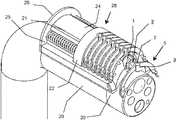
- FIG. 2shows an example embodiment of a multistaple loader for an applicator according to the invention. It consists of a housing ( 20 ) in the form of a tile, having a ventral surface complementary to the external surface of an endoscope. It can thus be fitted to a standard endoscope, in order to benefit from the lighting and visual examination means, and optionally aspiration means, integrated in such an endoscope.
- the dorsal part ( 21 )has a semitubular form, defining an enveloping surface the cross section of which corresponds to the cross section defined by the internal edges of the two arms ( 8 , 9 ) of a staple ( 5 ).
- the staplescan thus be positioned on this dorsal part ( 21 ).
- An arch ( 22 )is engaged on this dorsal part ( 21 ) and guided by two lateral flutes ( 23 ). This arch ( 22 ) is able to move longitudinally, under the action of two springs ( 24 , 25 ), bearing on a proximal front collar ( 26 ).
- the loadermoreover has a tubular recess ( 27 ) extending longitudinally, for introducing the previously described sleeve ( 1 ).
- the staplesare all placed transversely and adjacently to form a series of staples ( 5 ) parallel to one another.
- the connecting zone ( 7 )has a protrusion adjacent to that formed by the hooks ( 13 , 14 ), which makes it possible to maintain parallelism between the consecutive staples.
- the loader ( 28 )is placed straddling the distal end of the endoscope ( 29 ).
- the rod ( 2 )is pushed slightly out of the sleeve ( 1 ).
- the staple ( 5 ) at the distal front end of the series of adjacent staplesis pushed by the action of the arch ( 22 ) and comes to be housed in the reception zone of the rod ( 2 ) as shown in FIG. 3 .
- the other staplesare held in place around the dorsal zone ( 21 ) of the loader ( 28 ) by friction.
- the connecting zone ( 7 )is placed behind the stub ( 4 ), that is to say on the same side as the proximal end (on the operator side), whereas the stub is on the same side as the distal end (on the same side as the tissues to be held).
- the rod ( 2 )is withdrawn inside the sleeve ( 1 ) as shown in FIG. 4 .
- the arms ( 8 , 9 )then engage in the lateral recesses provided at the front end of the sleeve ( 1 ).
- the staple ( 5 )is then wedged between the stub ( 4 ) and the front surface of the sleeve ( 1 ), and can be manipulated by the conjoint movement of the sleeve ( 1 ) and rod ( 2 ). It is thus possible to move the staple by an external action in longitudinal axial movement and in rotation about the longitudinal axis, as shown in FIG. 5 .
- the points ( 10 , 11 )come to fit flush with the tissues, in the field of vision of the endoscope, and hook onto the tissues to be brought together.
- the applicatorcan advantageously be disposed on an endoscope retracted from the end of the latter so that the device does not enter the field of vision of the endoscope but so that the ends of the arms ( 8 , 9 ) of the staple ( 5 ) enter the field of vision of said endoscope.
Landscapes
- Health & Medical Sciences (AREA)
- Life Sciences & Earth Sciences (AREA)
- Surgery (AREA)
- General Health & Medical Sciences (AREA)
- Veterinary Medicine (AREA)
- Biomedical Technology (AREA)
- Heart & Thoracic Surgery (AREA)
- Medical Informatics (AREA)
- Molecular Biology (AREA)
- Animal Behavior & Ethology (AREA)
- Nuclear Medicine, Radiotherapy & Molecular Imaging (AREA)
- Public Health (AREA)
- Engineering & Computer Science (AREA)
- Physics & Mathematics (AREA)
- Biophysics (AREA)
- Optics & Photonics (AREA)
- Pathology (AREA)
- Radiology & Medical Imaging (AREA)
- Surgical Instruments (AREA)
- Endoscopes (AREA)
Abstract
Description
Claims (11)
Applications Claiming Priority (3)
| Application Number | Priority Date | Filing Date | Title |
|---|---|---|---|
| FR1551204AFR3032608B1 (en) | 2015-02-13 | 2015-02-13 | ENDOSCOPIC SURGERY SYSTEM FORMED ON THE ONE HAND BY A PLURALITY OF STAPLES AND ON THE OTHER HAND BY AN ENDOSCOPIC APPLICATOR. |
| FR1551204 | 2015-02-13 | ||
| PCT/FR2016/050330WO2016128693A1 (en) | 2015-02-13 | 2016-02-12 | Endoscopic surgery system consisting of a plurality of staples and an endoscopic applicator |
Publications (2)
| Publication Number | Publication Date |
|---|---|
| US20180000482A1 US20180000482A1 (en) | 2018-01-04 |
| US11166719B2true US11166719B2 (en) | 2021-11-09 |
Family
ID=53674025
Family Applications (1)
| Application Number | Title | Priority Date | Filing Date |
|---|---|---|---|
| US15/549,595Active2036-10-09US11166719B2 (en) | 2015-02-13 | 2016-02-12 | Endoscopic surgery system consisting of a plurality of staples and an endoscopic applicator |
Country Status (6)
| Country | Link |
|---|---|
| US (1) | US11166719B2 (en) |
| EP (1) | EP3256056B1 (en) |
| JP (1) | JP6806691B2 (en) |
| KR (1) | KR102548730B1 (en) |
| FR (1) | FR3032608B1 (en) |
| WO (1) | WO2016128693A1 (en) |
Families Citing this family (4)
| Publication number | Priority date | Publication date | Assignee | Title |
|---|---|---|---|---|
| FR3061425B1 (en) | 2017-01-03 | 2019-01-25 | Institut Hospitalo-Universitaire De Chirurgie Mini-Invasive Guidee Par L'image | SURGICAL CLIP WITH TWO MOBILE BRANCHES CONNECTED WITH A CROSS-LINK AREA |
| WO2021151923A1 (en) | 2020-01-30 | 2021-08-05 | Institut Hospitalo-Universitaire De Chirurgie Mini -Invasive Guidee Par L'image | Actuation handle for actuating a surgical applicator tool and applicator tool comprising a corresponding actuation handle |
| FR3139272B1 (en)* | 2022-09-02 | 2025-05-02 | Peters Surgical | cartridge for surgical staples |
| US12268385B2 (en) | 2023-05-11 | 2025-04-08 | Taurus Endoscopy SAS | Surgical staple |
Citations (18)
| Publication number | Priority date | Publication date | Assignee | Title |
|---|---|---|---|---|
| US4895289A (en)* | 1986-12-22 | 1990-01-23 | Ophthalmic Ventures Limited Partnership | Ophthalmic stapler |
| US5114065A (en)* | 1988-05-23 | 1992-05-19 | Technalytics, Inc. | Surgical stapler |
| US5395030A (en)* | 1992-06-04 | 1995-03-07 | Olympus Optical Co., Ltd. | Surgical device for stapling and fastening body tissues |
| US5456400A (en)* | 1993-04-22 | 1995-10-10 | United States Surgical Corporation | Apparatus and clip for fastening body tissue |
| EP0713684A2 (en) | 1992-10-09 | 1996-05-29 | Ethicon, Inc. | Endoscopic surgical stapling instrument with pivotable and rotatable staple cartridge |
| US20070055292A1 (en)* | 2005-09-02 | 2007-03-08 | Ortiz Mark S | Method and apparatus for endoscopically performing gastric reduction surgery in a single step |
| US20080269803A1 (en)* | 2007-04-25 | 2008-10-30 | Medtronic Vascular, Inc. | Arteriotomy staple with primary and secondary prongs |
| US20090072006A1 (en)* | 2007-03-08 | 2009-03-19 | Cardica, Inc. | Surgical Stapler With Splaying Mechanism |
| US20090275957A1 (en)* | 2008-05-01 | 2009-11-05 | Harris Jason L | Clip and delivery assembly used in forming a tissue fold |
| US20090272783A1 (en)* | 2008-05-01 | 2009-11-05 | Lawrence Crainich | Fastener and fastener applier having selective suture attachment |
| US20090272786A1 (en)* | 2008-05-01 | 2009-11-05 | Zeiner Mark S | Surgical stapling instrument for applying a large staple through a small delivery port and a method of using the surgical stapler to secure a tissue fold |
| US20110029015A1 (en)* | 2007-11-29 | 2011-02-03 | Mani, Inc. | Medical Staple And Magazine |
| US8133240B2 (en)* | 2001-10-24 | 2012-03-13 | Boston Scientific Scimed, Inc. | Multiple hemoclip system for an endoscope |
| US20120211543A1 (en)* | 2011-02-15 | 2012-08-23 | Euteneuer Charles L | Methods and apparatus for fixing sheet-like materials to a target tissue |
| US20130245642A1 (en)* | 2012-03-16 | 2013-09-19 | Ethicon, Inc. | Clamping devices for dispensing surgical fasteners into soft media |
| US20140263560A1 (en)* | 2012-09-25 | 2014-09-18 | Robert N Chase | Skin Stapler with Components Optimized for Construction with Plant Based Materials |
| US20150133966A1 (en)* | 2013-11-08 | 2015-05-14 | C.R. Bard, Inc. | Surgical fastener deployment system |
| US20160106420A1 (en)* | 2013-06-28 | 2016-04-21 | Valcare, Inc. | Device, system, and method to secure an article to a tissue |
Family Cites Families (3)
| Publication number | Priority date | Publication date | Assignee | Title |
|---|---|---|---|---|
| US5601224A (en)* | 1992-10-09 | 1997-02-11 | Ethicon, Inc. | Surgical instrument |
| DE60144328D1 (en)* | 2000-09-08 | 2011-05-12 | Abbott Vascular Inc | Surgical clamp |
| US8631991B2 (en)* | 2007-05-30 | 2014-01-21 | Ethicon Endo-Surgery, Inc. | Surgical instrument |
- 2015
- 2015-02-13FRFR1551204Apatent/FR3032608B1/enactiveActive
- 2016
- 2016-02-12EPEP16707917.7Apatent/EP3256056B1/enactiveActive
- 2016-02-12USUS15/549,595patent/US11166719B2/enactiveActive
- 2016-02-12JPJP2017542890Apatent/JP6806691B2/enactiveActive
- 2016-02-12KRKR1020177025370Apatent/KR102548730B1/enactiveActive
- 2016-02-12WOPCT/FR2016/050330patent/WO2016128693A1/ennot_activeCeased
Patent Citations (18)
| Publication number | Priority date | Publication date | Assignee | Title |
|---|---|---|---|---|
| US4895289A (en)* | 1986-12-22 | 1990-01-23 | Ophthalmic Ventures Limited Partnership | Ophthalmic stapler |
| US5114065A (en)* | 1988-05-23 | 1992-05-19 | Technalytics, Inc. | Surgical stapler |
| US5395030A (en)* | 1992-06-04 | 1995-03-07 | Olympus Optical Co., Ltd. | Surgical device for stapling and fastening body tissues |
| EP0713684A2 (en) | 1992-10-09 | 1996-05-29 | Ethicon, Inc. | Endoscopic surgical stapling instrument with pivotable and rotatable staple cartridge |
| US5456400A (en)* | 1993-04-22 | 1995-10-10 | United States Surgical Corporation | Apparatus and clip for fastening body tissue |
| US8133240B2 (en)* | 2001-10-24 | 2012-03-13 | Boston Scientific Scimed, Inc. | Multiple hemoclip system for an endoscope |
| US20070055292A1 (en)* | 2005-09-02 | 2007-03-08 | Ortiz Mark S | Method and apparatus for endoscopically performing gastric reduction surgery in a single step |
| US20090072006A1 (en)* | 2007-03-08 | 2009-03-19 | Cardica, Inc. | Surgical Stapler With Splaying Mechanism |
| US20080269803A1 (en)* | 2007-04-25 | 2008-10-30 | Medtronic Vascular, Inc. | Arteriotomy staple with primary and secondary prongs |
| US20110029015A1 (en)* | 2007-11-29 | 2011-02-03 | Mani, Inc. | Medical Staple And Magazine |
| US20090275957A1 (en)* | 2008-05-01 | 2009-11-05 | Harris Jason L | Clip and delivery assembly used in forming a tissue fold |
| US20090272783A1 (en)* | 2008-05-01 | 2009-11-05 | Lawrence Crainich | Fastener and fastener applier having selective suture attachment |
| US20090272786A1 (en)* | 2008-05-01 | 2009-11-05 | Zeiner Mark S | Surgical stapling instrument for applying a large staple through a small delivery port and a method of using the surgical stapler to secure a tissue fold |
| US20120211543A1 (en)* | 2011-02-15 | 2012-08-23 | Euteneuer Charles L | Methods and apparatus for fixing sheet-like materials to a target tissue |
| US20130245642A1 (en)* | 2012-03-16 | 2013-09-19 | Ethicon, Inc. | Clamping devices for dispensing surgical fasteners into soft media |
| US20140263560A1 (en)* | 2012-09-25 | 2014-09-18 | Robert N Chase | Skin Stapler with Components Optimized for Construction with Plant Based Materials |
| US20160106420A1 (en)* | 2013-06-28 | 2016-04-21 | Valcare, Inc. | Device, system, and method to secure an article to a tissue |
| US20150133966A1 (en)* | 2013-11-08 | 2015-05-14 | C.R. Bard, Inc. | Surgical fastener deployment system |
Also Published As
| Publication number | Publication date |
|---|---|
| EP3256056C0 (en) | 2024-12-04 |
| EP3256056A1 (en) | 2017-12-20 |
| JP2018504997A (en) | 2018-02-22 |
| EP3256056B1 (en) | 2024-12-04 |
| KR20170120621A (en) | 2017-10-31 |
| FR3032608B1 (en) | 2020-10-23 |
| FR3032608A1 (en) | 2016-08-19 |
| US20180000482A1 (en) | 2018-01-04 |
| KR102548730B1 (en) | 2023-06-28 |
| JP6806691B2 (en) | 2021-01-06 |
| WO2016128693A1 (en) | 2016-08-18 |
Similar Documents
| Publication | Publication Date | Title |
|---|---|---|
| US11857179B2 (en) | Devices and methods for suture placement | |
| US11969168B2 (en) | Surgical staple having two movable arms connected by a transverse connection area | |
| US20100106167A1 (en) | Flexible clip applier | |
| US20150045816A1 (en) | Clip applying apparatus with angled jaw | |
| US11166719B2 (en) | Endoscopic surgery system consisting of a plurality of staples and an endoscopic applicator | |
| JP2013135860A (en) | Actuator and detachable connector of flexible clip applicator | |
| EP3420924B1 (en) | Needle holder for endoscope, suture set, and suture system | |
| JP2020526282A (en) | Suture placement device and method | |
| JP2010004941A (en) | Cylindrical member and multiple clip application apparatus |
Legal Events
| Date | Code | Title | Description |
|---|---|---|---|
| AS | Assignment | Owner name:INSTITUT HOSPITALO-UNIVERSITAIRE DE CHIRURGIE MINI-INVASIVE GUIDEE PAR L'IMAGE S/C IRCAD, FRANCE Free format text:ASSIGNMENT OF ASSIGNORS INTEREST;ASSIGNORS:ALZAGA, AMILCAR;RIVA, PIETRO;REEL/FRAME:043815/0480 Effective date:20170918 Owner name:INSTITUT HOSPITALO-UNIVERSITAIRE DE CHIRURGIE MINI Free format text:ASSIGNMENT OF ASSIGNORS INTEREST;ASSIGNORS:ALZAGA, AMILCAR;RIVA, PIETRO;REEL/FRAME:043815/0480 Effective date:20170918 | |
| STPP | Information on status: patent application and granting procedure in general | Free format text:DOCKETED NEW CASE - READY FOR EXAMINATION | |
| STPP | Information on status: patent application and granting procedure in general | Free format text:NON FINAL ACTION MAILED | |
| STPP | Information on status: patent application and granting procedure in general | Free format text:RESPONSE TO NON-FINAL OFFICE ACTION ENTERED AND FORWARDED TO EXAMINER | |
| STPP | Information on status: patent application and granting procedure in general | Free format text:FINAL REJECTION MAILED | |
| STPP | Information on status: patent application and granting procedure in general | Free format text:DOCKETED NEW CASE - READY FOR EXAMINATION | |
| STPP | Information on status: patent application and granting procedure in general | Free format text:FINAL REJECTION MAILED | |
| STPP | Information on status: patent application and granting procedure in general | Free format text:RESPONSE AFTER FINAL ACTION FORWARDED TO EXAMINER | |
| STPP | Information on status: patent application and granting procedure in general | Free format text:ADVISORY ACTION MAILED | |
| STPP | Information on status: patent application and granting procedure in general | Free format text:DOCKETED NEW CASE - READY FOR EXAMINATION | |
| STPP | Information on status: patent application and granting procedure in general | Free format text:NON FINAL ACTION MAILED | |
| STPP | Information on status: patent application and granting procedure in general | Free format text:RESPONSE TO NON-FINAL OFFICE ACTION ENTERED AND FORWARDED TO EXAMINER | |
| STPP | Information on status: patent application and granting procedure in general | Free format text:NOTICE OF ALLOWANCE MAILED -- APPLICATION RECEIVED IN OFFICE OF PUBLICATIONS | |
| STPP | Information on status: patent application and granting procedure in general | Free format text:PUBLICATIONS -- ISSUE FEE PAYMENT RECEIVED | |
| STPP | Information on status: patent application and granting procedure in general | Free format text:PUBLICATIONS -- ISSUE FEE PAYMENT VERIFIED | |
| STCF | Information on status: patent grant | Free format text:PATENTED CASE | |
| AS | Assignment | Owner name:TAURUS ENDOSCOPY, FRANCE Free format text:CHANGE OF ADDRESS;ASSIGNOR:INSTITUT HOSPITALO-UNIVERSITAIRE DE CHIRURGIE MINI -INVASIVE GUIDEE PAR L'IMAGE;REEL/FRAME:067591/0466 Effective date:20231207 | |
| AS | Assignment | Owner name:TAURUS ENDOSCOPY, FRANCE Free format text:CORRECTIVE ASSIGNMENT TO CORRECT THE THE NATURE OF CONVEYANCE FROM CHANGE OF ADDRESS TO ASSIGNMENT PREVIOUSLY RECORDED AT REEL: 67591 FRAME: 466. ASSIGNOR(S) HEREBY CONFIRMS THE ASSIGNMENT;ASSIGNOR:INSTITUT HOSPITALO-UNIVERSITAIRE DE CHIRURGIE MINI -INVASIVE GUIDEE PAR L'IMAGE;REEL/FRAME:067661/0446 Effective date:20231207 | |
| MAFP | Maintenance fee payment | Free format text:PAYMENT OF MAINTENANCE FEE, 4TH YEAR, LARGE ENTITY (ORIGINAL EVENT CODE: M1551); ENTITY STATUS OF PATENT OWNER: LARGE ENTITY Year of fee payment:4 |