US11165272B2 - Device charger attachment - Google Patents
Device charger attachmentDownload PDFInfo
- Publication number
- US11165272B2 US11165272B2US14/872,643US201514872643AUS11165272B2US 11165272 B2US11165272 B2US 11165272B2US 201514872643 AUS201514872643 AUS 201514872643AUS 11165272 B2US11165272 B2US 11165272B2
- Authority
- US
- United States
- Prior art keywords
- module
- add
- communication device
- power
- portable electronic
- Prior art date
- Legal status (The legal status is an assumption and is not a legal conclusion. Google has not performed a legal analysis and makes no representation as to the accuracy of the status listed.)
- Active, expires
Links
Images


Classifications
- H02J7/025—
- H—ELECTRICITY
- H02—GENERATION; CONVERSION OR DISTRIBUTION OF ELECTRIC POWER
- H02J—CIRCUIT ARRANGEMENTS OR SYSTEMS FOR SUPPLYING OR DISTRIBUTING ELECTRIC POWER; SYSTEMS FOR STORING ELECTRIC ENERGY
- H02J50/00—Circuit arrangements or systems for wireless supply or distribution of electric power
- H02J50/10—Circuit arrangements or systems for wireless supply or distribution of electric power using inductive coupling
- H02J50/12—Circuit arrangements or systems for wireless supply or distribution of electric power using inductive coupling of the resonant type
- H—ELECTRICITY
- H02—GENERATION; CONVERSION OR DISTRIBUTION OF ELECTRIC POWER
- H02J—CIRCUIT ARRANGEMENTS OR SYSTEMS FOR SUPPLYING OR DISTRIBUTING ELECTRIC POWER; SYSTEMS FOR STORING ELECTRIC ENERGY
- H02J50/00—Circuit arrangements or systems for wireless supply or distribution of electric power
- H02J50/80—Circuit arrangements or systems for wireless supply or distribution of electric power involving the exchange of data, concerning supply or distribution of electric power, between transmitting devices and receiving devices
- H—ELECTRICITY
- H02—GENERATION; CONVERSION OR DISTRIBUTION OF ELECTRIC POWER
- H02J—CIRCUIT ARRANGEMENTS OR SYSTEMS FOR SUPPLYING OR DISTRIBUTING ELECTRIC POWER; SYSTEMS FOR STORING ELECTRIC ENERGY
- H02J7/00—Circuit arrangements for charging or depolarising batteries or for supplying loads from batteries
- H02J7/0042—Circuit arrangements for charging or depolarising batteries or for supplying loads from batteries characterised by the mechanical construction
Definitions
- the present disclosureis related generally to charging of portable communication devices, and, more particularly, to a system and method for wirelessly interfacing such as device to a companion device for charging.
- FIG. 1is a simplified schematic of an example device with respect to which embodiments of the presently disclosed principles may be implemented;
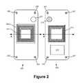
- FIG. 2is a simplified plan view of a portable communication device and a mating back cover module in accordance with an embodiment of the disclosed principles
- FIG. 3is a cross-sectional end view of portable communication device and a docked back cover module in accordance with an embodiment of the disclosed principles
- FIG. 4is a data diagram showing two simplified data plots corresponding to different charging profiles in accordance with an embodiment of the disclosed principles.
- a Receiver (RX)/Transmitter (TX) wireless charging solutionis provided.
- RXReceiver
- TXTransmitter
- magnetic resonant wireless chargingis used in an embodiment with a contactless back cover.
- the device batterycan be charged with the back cover in place, and the device may also provide power for back cover electronic units via various on time duty cycles to save power.
- the back cover modulestores power in one or more capacitors to provide power between TX bursts.
- the back cover resonatorenhances efficiency of the device resonator in a further embodiment.
- the ability to exchange power between the device and the back cover deviceallows users to personalize their device with particularly applicable back cover electronics. That is, the user is able to attach a selected back cover to the device and power it without a connector interface.
- the back covermay support an e-ink low power display, biomedical functions etc.
- A4WPmagnetic resonance charging
- the useris able to charge wearables such as battery powered earpieces by placing them near the back of the device.
- Communication between the back cover circuitry and the devicemay be via the Bluetooth Low Energy protocol which is integrated within the A4WP function.
- Power consumptionshould be managed for portable devices, since they are typically battery-powered, and a battery charge must typically last for a long period of time, e.g., a day. Thus, powering the back cover module should be executed in an efficient manner.
- the power exchangein order to increase the efficiency of power exchange between the device and the back cover module, the power exchange is driven with a duty cycle that is generally less than 100%.
- a storage capacitor within the back cover modulemay provide interim power while the wireless charge field is in a low power mode.
- the charging duty cycleshould be a function of, or at least not inconsistent with, the power demands of the operation being performed. For instance while charging a wearable device, it may be logical to use a 100% duty cycle, since you are charging the battery on the remote device.
- Wireless exchange between the device and the back cover moduleis facilitated by eliminating or minimizing shielding on the module receiver resonator so that the transmitter flux extends beyond the back cover coil, allowing coupling to the external device.
- This elimination of shieldingalso enables charging of the device on an A4WP charging pad.
- the devicein order for the device to couple with the back cover module, the device is configured to detect the presence of the module. In an embodiment, detection of the back cover module is executed via a paired permanent magnet in the back cover module and a magnetic pick-up on the device. Alternatively, short wireless pings from the device may be used to power the back cover module and allow it to advertise per the A4WP specification. This may require a minimum transmission period in order to maintain compatibility with external A4WP devices.
- FIG. 1illustrates an example mobile device within which embodiments of the disclosed principles may be implemented, it will be appreciated that other device types may be used, including but not limited to laptop computers, tablet computers, embedded automobile computing systems and so on.
- FIG. 1shows an exemplary device 110 forming part of an environment within which aspects of the present disclosure may be implemented.
- the schematic diagramillustrates a user device 110 including several exemplary components. It will be appreciated that additional or alternative components may be used in a given implementation depending upon user preference, component availability, price point and other considerations.
- the components of the user device 110include a display screen 120 , applications (e.g., programs) 130 , a processor 140 , a memory 150 , one or more input components 160 such as speech and text input facilities, and one or more output components 170 such as text and audible output facilities, e.g., one or more speakers.
- the processor 140may be any of a microprocessor, microcomputer, application-specific integrated circuit, or the like.
- the processor 140can be implemented by one or more microprocessors or controllers from any desired family or manufacturer.
- the memory 150may reside on the same integrated circuit as the processor 140 . Additionally or alternatively, the memory 150 may be accessed via a network, e.g., via cloud-based storage.
- the memory 150may include a random access memory (i.e., Synchronous Dynamic Random Access Memory (SDRAM), Dynamic Random Access Memory (DRAM), RAMBUS Dynamic Random Access Memory (RDRM) or any other type of random access memory device or system). Additionally or alternatively, the memory 150 may include a read only memory (i.e., a hard drive, flash memory or any other desired type of memory device).
- SDRAMSynchronous Dynamic Random Access Memory
- DRAMDynamic Random Access Memory
- RDRMRAMBUS Dynamic Random Access Memory
- the memory 150may include a read only memory (i.e., a hard
- the information that is stored by the memory 150can include program code associated with one or more operating systems or applications as well as informational data, e.g., program parameters, process data, etc.
- the operating system and applicationsare typically implemented via executable instructions stored in a non-transitory computer readable medium (e.g., memory 150 ) to control basic functions of the electronic device 110 .
- Such functionsmay include, for example, interaction among various internal components and storage and retrieval of applications and data to and from the memory 150 .
- applicationstypically utilize the operating system to provide more specific functionality, such as file system service and handling of protected and unprotected data stored in the memory 150 .
- applicationsmay provide standard or required functionality of the user device 110 , in other cases applications provide optional or specialized functionality, and may be supplied by third party vendors or the device manufacturer.
- informational datae.g., program parameters and process data
- this non-executable informationcan be referenced, manipulated, or written by the operating system or an application.
- informational datacan include, for example, data that are preprogrammed into the device during manufacture, data that are created by the device or added by the user, or any of a variety of types of information that are uploaded to, downloaded from, or otherwise accessed at servers or other devices with which the device is in communication during its ongoing operation.
- the device 110further includes one or more back cover module sensors 180 configured to provide a signal indicative of the presence or absence of a back cover module on the device 110 .
- a power supply 190such as a battery or fuel cell, may be included for providing power to the device 110 and its components. All or some of the internal components communicate with one another by way of one or more shared or dedicated internal communication links 195 , such as an internal bus.
- the device 110is programmed such that the processor 140 and memory 150 interact with the other components of the device 110 to perform a variety of functions.
- the processor 140may include or implement various modules and execute programs for initiating different activities such as launching an application, transferring data and toggling through various graphical user interface objects (e.g., toggling through various display icons that are linked to executable applications).
- FIG. 2this figure shows a simplified plan view of a portable communication device, i.e., a mobile device, and a mating back cover module.
- the portable communication device 200includes a resonator 201 overlying a shield 203 .
- the portable communication device 200includes one or more alignment and retaining features to keep the back cover module attached and in place when the devices are docked together.
- these featuresinclude a plurality of magnets 205 , which are positioned to register with corresponding ferrous disks 207 on the back cover module 209 .
- the portable communication device 200also includes a magnetic pick-up 211 in an embodiment, positioned to register with a corresponding detection magnet 213 on the back cover module 209 .
- the back cover module 209also includes a resonator 215 but no shield. In this way, the flux of the resonator 201 associated with the portable communication device 200 is able to encompass the resonator 215 of the back cover module 209 .
- the back cover module 209may be a full electronic module
- a printed circuit board (PCB) 217is also shown. It will be appreciated that the portable communication device 200 also includes a PCB.
- Wireless exchange between the device and the back cover moduleis facilitated by eliminating or minimizing shielding on the module 209 resonator 215 so that the transmitter flux of the portable device 200 resonator 201 extends beyond the back cover coil, allowing coupling to the external device.
- This elimination of shieldingalso enables charging of the device on an ordinary A4WP charging pad.
- FIG. 3shows a cross-sectional end view of the portable communication device 200 and the docked back cover module 213 .
- the cross-sectionis taken through each device at its respective bisector A, B.
- the shielded resonator coil 201 of the portable communication device 200generates a magnetic field represented by a flux emission and receipt pattern 301 that encompasses the resonator coil 215 of the back cover module 209 .
- the back cover module 209may include an e-ink low power display, biomedical function modules and so on. Moreover, although the back cover module 209 is shown to be the same size as the portable device in the illustrated embodiments, it will be appreciated that the back cover module 209 may be of a substantial size and form.
- the systemallows magnetic resonance charging (A4WP) to be used to charge wearables such as battery powered earpieces by placing them near the back of the device.
- A4WPmagnetic resonance charging
- the power exchangemay be driven with a duty cycle that is generally less than 100% but that more specifically depends upon the character of the module 209 .
- a duty cyclethat is generally less than 100% but that more specifically depends upon the character of the module 209 .
- a certain duty cyclemay be used, with a storage capacitor in the module 209 being used to buffer power delivery.
- FIG. 4shows a pair of duty cycle maps 401 , 403 for power exchange from the portable communication device 200 to the add on module 209 .
- the plot 401shows a duty cycle for power transmission when the external module 209 is a logical unit, e.g., an active module running at least simple code for executing some function. In this case, the goal is simply to maintain power, and the applicable duty cycle is 50%.
- the plot 403shows a duty cycle for power transmission when the external module 209 is a power unit to be filled, e.g., a battery. In this case, the goal is to charge the battery and so the applicable duty cycle is 100%.
- the deviceis configured to detect the presence and identity of the module 209 .
- detection of the back cover module 209may be executed via a paired permanent magnet in the back cover module 209 and a magnetic pick-up on the device 200 .
- thisallows detection of the module 209 , it will not typically provide sufficient data capability to identify the type of the module 209 in an environment where it is possible to have different module types.
- the device 200emits short wireless pings to power the back cover module 209 and allow it to then advertise per the A4WP specification. In this way, the device 209 is able to identify the module 209 and hence its needs and capabilities.
Landscapes
- Engineering & Computer Science (AREA)
- Power Engineering (AREA)
- Computer Networks & Wireless Communication (AREA)
- Charge And Discharge Circuits For Batteries Or The Like (AREA)
Abstract
Description
Claims (14)
Priority Applications (1)
| Application Number | Priority Date | Filing Date | Title |
|---|---|---|---|
| US14/872,643US11165272B2 (en) | 2015-10-01 | 2015-10-01 | Device charger attachment |
Applications Claiming Priority (1)
| Application Number | Priority Date | Filing Date | Title |
|---|---|---|---|
| US14/872,643US11165272B2 (en) | 2015-10-01 | 2015-10-01 | Device charger attachment |
Publications (2)
| Publication Number | Publication Date |
|---|---|
| US20170098952A1 US20170098952A1 (en) | 2017-04-06 |
| US11165272B2true US11165272B2 (en) | 2021-11-02 |
Family
ID=58447657
Family Applications (1)
| Application Number | Title | Priority Date | Filing Date |
|---|---|---|---|
| US14/872,643Active2036-06-01US11165272B2 (en) | 2015-10-01 | 2015-10-01 | Device charger attachment |
Country Status (1)
| Country | Link |
|---|---|
| US (1) | US11165272B2 (en) |
Cited By (2)
| Publication number | Priority date | Publication date | Assignee | Title |
|---|---|---|---|---|
| US20220264751A1 (en)* | 2021-02-15 | 2022-08-18 | Samsung Display Co., Ltd. | Display device and method of manufacturing the same |
| US11444485B2 (en)* | 2019-02-05 | 2022-09-13 | Mojo Mobility, Inc. | Inductive charging system with charging electronics physically separated from charging coil |
Families Citing this family (3)
| Publication number | Priority date | Publication date | Assignee | Title |
|---|---|---|---|---|
| US10469119B2 (en)* | 2017-05-25 | 2019-11-05 | Spigen Korea Co., Ltd. | Magnetic mount for electronic devices |
| US12224788B2 (en) | 2017-05-25 | 2025-02-11 | Spigen Korea Co., Ltd. | Magnetic auxiliary devices for mobile devices |
| US12191902B2 (en) | 2017-05-25 | 2025-01-07 | Spigen Korea Co., Ltd. | Mobile electronic device cases for electromagnetic shielding |
Citations (9)
| Publication number | Priority date | Publication date | Assignee | Title |
|---|---|---|---|---|
| US20070182367A1 (en)* | 2006-01-31 | 2007-08-09 | Afshin Partovi | Inductive power source and charging system |
| US20090096413A1 (en)* | 2006-01-31 | 2009-04-16 | Mojo Mobility, Inc. | System and method for inductive charging of portable devices |
| US20110181238A1 (en)* | 2007-12-21 | 2011-07-28 | Soar Roger J | Modular pocket with inductive power and data |
| US20120153732A1 (en)* | 2008-09-27 | 2012-06-21 | Kurs Andre B | Wireless energy transfer for computer peripheral applications |
| US20120189146A1 (en)* | 2011-01-21 | 2012-07-26 | Stmicroelectronics (Rousset) Sas | Contactless recharging of the battery of a portable object by a telephone |
| US20130082536A1 (en)* | 2011-03-22 | 2013-04-04 | Access Business Group International Llc | System and method for improved control in wireless power supply systems |
| US20140028252A1 (en)* | 2010-12-31 | 2014-01-30 | Nokia Corporation | Power transfer |
| US20150180284A1 (en)* | 2013-12-20 | 2015-06-25 | Samsung Electro-Mechanics Co., Ltd. | Apparatus for transmitting and receiving wireless power |
| US20150256226A1 (en)* | 2014-03-09 | 2015-09-10 | Xintian E. Lin | Techniques for Wireless Charging Communication |
- 2015
- 2015-10-01USUS14/872,643patent/US11165272B2/enactiveActive
Patent Citations (9)
| Publication number | Priority date | Publication date | Assignee | Title |
|---|---|---|---|---|
| US20070182367A1 (en)* | 2006-01-31 | 2007-08-09 | Afshin Partovi | Inductive power source and charging system |
| US20090096413A1 (en)* | 2006-01-31 | 2009-04-16 | Mojo Mobility, Inc. | System and method for inductive charging of portable devices |
| US20110181238A1 (en)* | 2007-12-21 | 2011-07-28 | Soar Roger J | Modular pocket with inductive power and data |
| US20120153732A1 (en)* | 2008-09-27 | 2012-06-21 | Kurs Andre B | Wireless energy transfer for computer peripheral applications |
| US20140028252A1 (en)* | 2010-12-31 | 2014-01-30 | Nokia Corporation | Power transfer |
| US20120189146A1 (en)* | 2011-01-21 | 2012-07-26 | Stmicroelectronics (Rousset) Sas | Contactless recharging of the battery of a portable object by a telephone |
| US20130082536A1 (en)* | 2011-03-22 | 2013-04-04 | Access Business Group International Llc | System and method for improved control in wireless power supply systems |
| US20150180284A1 (en)* | 2013-12-20 | 2015-06-25 | Samsung Electro-Mechanics Co., Ltd. | Apparatus for transmitting and receiving wireless power |
| US20150256226A1 (en)* | 2014-03-09 | 2015-09-10 | Xintian E. Lin | Techniques for Wireless Charging Communication |
Non-Patent Citations (1)
| Title |
|---|
| IDT Wireless Power Transmitter/Receiver; Preliminary Product Datasheet; Revision 0.0.05; Published in 2015 Integrated Device Technology Inc. |
Cited By (5)
| Publication number | Priority date | Publication date | Assignee | Title |
|---|---|---|---|---|
| US11444485B2 (en)* | 2019-02-05 | 2022-09-13 | Mojo Mobility, Inc. | Inductive charging system with charging electronics physically separated from charging coil |
| US11811238B2 (en) | 2019-02-05 | 2023-11-07 | Mojo Mobility Inc. | Inductive charging system with charging electronics physically separated from charging coil |
| US20220264751A1 (en)* | 2021-02-15 | 2022-08-18 | Samsung Display Co., Ltd. | Display device and method of manufacturing the same |
| US11825613B2 (en)* | 2021-02-15 | 2023-11-21 | Samsung Display Co., Ltd. | Display device and method of manufacturing the same |
| US12108545B2 (en) | 2021-02-15 | 2024-10-01 | Samsung Display Co., Ltd. | Display device and method of manufacturing the same |
Also Published As
| Publication number | Publication date |
|---|---|
| US20170098952A1 (en) | 2017-04-06 |
Similar Documents
| Publication | Publication Date | Title |
|---|---|---|
| US11995251B2 (en) | Wireless charging system, chip, and wireless charging circuit | |
| US11165272B2 (en) | Device charger attachment | |
| EP3347965B1 (en) | Electronic device and method for wireless charging in electronic device | |
| US9640921B2 (en) | Electrical connector and electronic device including the same | |
| RU2618000C2 (en) | Compatibility between nfc and wct (wireless charging technology) | |
| KR102511514B1 (en) | Device and method for fast charging using various charge method | |
| CN108450040B (en) | Electronic equipment and accessory equipment for electronic equipment | |
| KR102232279B1 (en) | Cradle for electronic device | |
| US10340723B2 (en) | Electronic device and method for wireless charging in electronic device | |
| US9252890B2 (en) | Near field communication device and method for saving applied power | |
| US10693320B2 (en) | Wireless charging | |
| US9692253B2 (en) | Mobile terminal and method for controlling charging and charger therefor | |
| KR102550590B1 (en) | Connector and electronic device including the same | |
| TWI514713B (en) | Device and method for power delivery including out-of-band communication,and machine-readable storage | |
| KR20180032902A (en) | Wireless power transmission apparatus in electronic device and method thereof | |
| CN113675636A (en) | Electronic device and method for electronic device to identify connection terminal of external device | |
| CN106465078A (en) | Information exchange for handheld electronic devices | |
| US11128169B2 (en) | Electronic device including a plurality of wireless charge coils and operating method thereof | |
| US20170162929A1 (en) | Charging Cable | |
| KR20170098123A (en) | Accessory apparatus and information display method using the same | |
| CN208939600U (en) | System for beacon and/or the wireless charging of sensor device | |
| US20160234359A1 (en) | Contactless devices and methods of use thereof | |
| KR102756804B1 (en) | A wireless charging device communicating with an electronic device and a communication method of the wireless charging device | |
| TWI403038B (en) | Electronic system with secured data accessing | |
| KR102197008B1 (en) | Structure for assembling frames and electronic device therof |
Legal Events
| Date | Code | Title | Description |
|---|---|---|---|
| AS | Assignment | Owner name:MOTOROLA MOBILITY LLC, ILLINOIS Free format text:ASSIGNMENT OF ASSIGNORS INTEREST;ASSIGNOR:WINKLER, DAVID A;REEL/FRAME:036705/0690 Effective date:20151001 | |
| STPP | Information on status: patent application and granting procedure in general | Free format text:NON FINAL ACTION MAILED | |
| STPP | Information on status: patent application and granting procedure in general | Free format text:RESPONSE TO NON-FINAL OFFICE ACTION ENTERED AND FORWARDED TO EXAMINER | |
| STPP | Information on status: patent application and granting procedure in general | Free format text:NOTICE OF ALLOWANCE MAILED -- APPLICATION RECEIVED IN OFFICE OF PUBLICATIONS | |
| STCB | Information on status: application discontinuation | Free format text:ABANDONED -- FAILURE TO PAY ISSUE FEE | |
| STPP | Information on status: patent application and granting procedure in general | Free format text:NOTICE OF ALLOWANCE MAILED -- APPLICATION RECEIVED IN OFFICE OF PUBLICATIONS | |
| STPP | Information on status: patent application and granting procedure in general | Free format text:DOCKETED NEW CASE - READY FOR EXAMINATION | |
| STPP | Information on status: patent application and granting procedure in general | Free format text:NOTICE OF ALLOWANCE MAILED -- APPLICATION RECEIVED IN OFFICE OF PUBLICATIONS | |
| STPP | Information on status: patent application and granting procedure in general | Free format text:PUBLICATIONS -- ISSUE FEE PAYMENT RECEIVED | |
| STPP | Information on status: patent application and granting procedure in general | Free format text:PUBLICATIONS -- ISSUE FEE PAYMENT VERIFIED | |
| STCF | Information on status: patent grant | Free format text:PATENTED CASE | |
| FEPP | Fee payment procedure | Free format text:MAINTENANCE FEE REMINDER MAILED (ORIGINAL EVENT CODE: REM.); ENTITY STATUS OF PATENT OWNER: LARGE ENTITY |