US11164361B2 - Generating floor maps for buildings from automated analysis of visual data of the buildings' interiors - Google Patents
Generating floor maps for buildings from automated analysis of visual data of the buildings' interiorsDownload PDFInfo
- Publication number
- US11164361B2 US11164361B2US17/080,604US202017080604AUS11164361B2US 11164361 B2US11164361 B2US 11164361B2US 202017080604 AUS202017080604 AUS 202017080604AUS 11164361 B2US11164361 B2US 11164361B2
- Authority
- US
- United States
- Prior art keywords
- room
- images
- building
- floor map
- information
- Prior art date
- Legal status (The legal status is an assumption and is not a legal conclusion. Google has not performed a legal analysis and makes no representation as to the accuracy of the status listed.)
- Active
Links
Images


Classifications
- G—PHYSICS
- G06—COMPUTING OR CALCULATING; COUNTING
- G06T—IMAGE DATA PROCESSING OR GENERATION, IN GENERAL
- G06T15/00—3D [Three Dimensional] image rendering
- G06T15/10—Geometric effects
- G—PHYSICS
- G06—COMPUTING OR CALCULATING; COUNTING
- G06T—IMAGE DATA PROCESSING OR GENERATION, IN GENERAL
- G06T17/00—Three dimensional [3D] modelling, e.g. data description of 3D objects
- G—PHYSICS
- G01—MEASURING; TESTING
- G01C—MEASURING DISTANCES, LEVELS OR BEARINGS; SURVEYING; NAVIGATION; GYROSCOPIC INSTRUMENTS; PHOTOGRAMMETRY OR VIDEOGRAMMETRY
- G01C21/00—Navigation; Navigational instruments not provided for in groups G01C1/00 - G01C19/00
- G01C21/005—Navigation; Navigational instruments not provided for in groups G01C1/00 - G01C19/00 with correlation of navigation data from several sources, e.g. map or contour matching
- G—PHYSICS
- G01—MEASURING; TESTING
- G01C—MEASURING DISTANCES, LEVELS OR BEARINGS; SURVEYING; NAVIGATION; GYROSCOPIC INSTRUMENTS; PHOTOGRAMMETRY OR VIDEOGRAMMETRY
- G01C21/00—Navigation; Navigational instruments not provided for in groups G01C1/00 - G01C19/00
- G01C21/20—Instruments for performing navigational calculations
- G01C21/206—Instruments for performing navigational calculations specially adapted for indoor navigation
- G—PHYSICS
- G01—MEASURING; TESTING
- G01C—MEASURING DISTANCES, LEVELS OR BEARINGS; SURVEYING; NAVIGATION; GYROSCOPIC INSTRUMENTS; PHOTOGRAMMETRY OR VIDEOGRAMMETRY
- G01C21/00—Navigation; Navigational instruments not provided for in groups G01C1/00 - G01C19/00
- G01C21/38—Electronic maps specially adapted for navigation; Updating thereof
- G01C21/3804—Creation or updating of map data
- G01C21/3807—Creation or updating of map data characterised by the type of data
- G01C21/383—Indoor data
- G—PHYSICS
- G01—MEASURING; TESTING
- G01C—MEASURING DISTANCES, LEVELS OR BEARINGS; SURVEYING; NAVIGATION; GYROSCOPIC INSTRUMENTS; PHOTOGRAMMETRY OR VIDEOGRAMMETRY
- G01C21/00—Navigation; Navigational instruments not provided for in groups G01C1/00 - G01C19/00
- G01C21/38—Electronic maps specially adapted for navigation; Updating thereof
- G01C21/3804—Creation or updating of map data
- G01C21/3833—Creation or updating of map data characterised by the source of data
- G01C21/3848—Data obtained from both position sensors and additional sensors
- G—PHYSICS
- G06—COMPUTING OR CALCULATING; COUNTING
- G06T—IMAGE DATA PROCESSING OR GENERATION, IN GENERAL
- G06T7/00—Image analysis
- G06T7/50—Depth or shape recovery
- G06T7/55—Depth or shape recovery from multiple images
- G—PHYSICS
- G06—COMPUTING OR CALCULATING; COUNTING
- G06T—IMAGE DATA PROCESSING OR GENERATION, IN GENERAL
- G06T7/00—Image analysis
- G06T7/70—Determining position or orientation of objects or cameras
- G06T7/73—Determining position or orientation of objects or cameras using feature-based methods
- H—ELECTRICITY
- H04—ELECTRIC COMMUNICATION TECHNIQUE
- H04N—PICTORIAL COMMUNICATION, e.g. TELEVISION
- H04N23/00—Cameras or camera modules comprising electronic image sensors; Control thereof
- H04N23/60—Control of cameras or camera modules
- H04N23/698—Control of cameras or camera modules for achieving an enlarged field of view, e.g. panoramic image capture
- H04N5/23238—
- G—PHYSICS
- G06—COMPUTING OR CALCULATING; COUNTING
- G06T—IMAGE DATA PROCESSING OR GENERATION, IN GENERAL
- G06T2207/00—Indexing scheme for image analysis or image enhancement
- G06T2207/10—Image acquisition modality
- G06T2207/10016—Video; Image sequence
- G—PHYSICS
- G06—COMPUTING OR CALCULATING; COUNTING
- G06T—IMAGE DATA PROCESSING OR GENERATION, IN GENERAL
- G06T2210/00—Indexing scheme for image generation or computer graphics
- G06T2210/04—Architectural design, interior design
Definitions
- the following disclosurerelates generally to techniques for automatically generating mapping information for a defined area using video or related visual image sequences acquired of the area, and for subsequently using the generated mapping information in one or more manners, such as to automatically generate a floor map of a building from analysis of video captured in the building's interior.
- FIGS. 1A-1Bare diagrams depicting an exemplary building interior environment and computing system(s) for use in embodiments of the present disclosure, such as for performing automated operations to generate mapping information representing the building interior.
- FIGS. 2A-2Oillustrate examples of automated operations for analyzing video or other sequences of images from a building's interior and for generating a corresponding floor map for the building.
- FIG. 3is a block diagram illustrating computing systems suitable for executing embodiments of one or more systems that perform at least some of the techniques described in the present disclosure.
- FIG. 4illustrates an example embodiment of a flow diagram for a Visual data Capture and Analysis (VCA) system routine in accordance with an embodiment of the present disclosure.
- VCAVisual data Capture and Analysis
- FIGS. 5A-5Billustrate an example embodiment of a flow diagram for a Visual data-To-Floor Map (VTFM) system routine in accordance with an embodiment of the present disclosure.
- VTFMVisual data-To-Floor Map
- FIG. 6illustrates an example embodiment of a flow diagram for a Building Map Viewer system routine in accordance with an embodiment of the present disclosure.
- the present disclosuredescribes techniques for using one or more computing devices to perform automated operations related to analyzing video acquired along a path through a defined area, as part of generating mapping information of the defined area for subsequent use in one or more further automated manners, or instead analyzing other types of image sequences along such a path followed by similar generating of mapping information.
- the defined areaincludes an interior of a multi-room building (e.g., a house, office, etc.), and the generated information includes a 3D (three-dimensional) floor map model of the building that is generated from an analysis of image frames of continuous video acquired along a path through the interior of the building, with the image analysis identifying shapes and sizes of objects in the building interior (e.g., doors, windows, walls, etc.), as well as determining borders between walls, floors and ceilings.
- a multi-room buildinge.g., a house, office, etc.
- the generated informationincludes a 3D (three-dimensional) floor map model of the building that is generated from an analysis of image frames of continuous video acquired along a path through the interior of the building, with the image analysis identifying shapes and sizes of objects in the building interior (e.g., doors, windows, walls, etc.), as well as determining borders between walls, floors and ceilings.
- the captured videomay, for example, be 360° video (e.g., video with frames that are each a spherical panorama image having 360° of coverage along at least one plane, such as 360° of coverage along a horizontal plane and around a vertical axis) acquired using a video acquisition device with a spherical camera having one or more fisheye lenses to capture 360 degrees horizontally, and in at least some such embodiments, the generating of the mapping information is further performed without having or using information acquired from any depth-sensing equipment about distances from the acquisition locations of the video/images to walls or other objects in the surrounding building interior.
- 360° videoe.g., video with frames that are each a spherical panorama image having 360° of coverage along at least one plane, such as 360° of coverage along a horizontal plane and around a vertical axis
- the generating of the mapping informationis further performed without having or using information acquired from any depth-sensing equipment about distances from the acquisition locations of the video/images to walls or other objects in
- the mapping-related information generated from the analysis of the video image frames (or other sequence of images)includes a 2D (two-dimensional) floor map of the building, such as an overhead view (e.g., an orthographic top view) of a schematic floor map, but without including or displaying height information in the same manner as visualizations of the 3D floor map model—if the 3D floor map model is generated first based on three-dimensional information obtained from the image analysis, such a 2D floor map may, for example, be generated from the 3D floor map model by removing height-related information for the rooms of the building.
- a 2D floor map of the buildingsuch as an overhead view (e.g., an orthographic top view) of a schematic floor map, but without including or displaying height information in the same manner as visualizations of the 3D floor map model—if the 3D floor map model is generated first based on three-dimensional information obtained from the image analysis, such a 2D floor map may, for example, be generated from the 3D floor map model by removing height-related information for the rooms
- the generated 3D floor map model and/or 2D floor map and/or other generated mapping-related informationmay be further used in one or more manners in various embodiments, such as for controlling navigation of mobile devices (e.g., autonomous vehicles), for display on one or more client devices in corresponding GUIs (graphical user interfaces), etc. Additional details are included below regarding the automated operations of the computing device(s) involved in the generating of the mapping information, and some or all of the techniques described herein may, in at least some embodiments, be performed via automated operations of a Visual data-To-Floor Map (“VTFM”) system, as discussed further below.
- VTFMVisual data-To-Floor Map
- the automated operations of the VTFM systemmay include selecting, from one or more videos captured of at least the interior of a building (e.g., along a path through the multiple rooms of a house or other multi-room building), video frames to include in an image group with a sequence of multiple images to use in the automated analysis and determination of a floor map (and optionally other mapping related information) for the building—in other embodiments in which another type of sequence of images of a building's interior are available that are not video frames (e.g., with each image having an acquisition location that is separated by only small distances from acquisition location(s) of one or more neighboring images, such as 3 feet or less, or 6 feet or less), similar automated techniques may be used to select an image group with a sequence of some or all of those images to use in the automated analysis and determination of the mapping related information for the building.
- similar automated techniquesmay be used to select an image group with a sequence of some or all of those images to use in the automated analysis and determination of the mapping related information for the building.
- the selection of the sequence of video frames or other images to use in the image groupmay be performed in various manners in various embodiments, including to select all available frames/images or instead to select only a subset of the available frames/images, such as frames/images that satisfy one or more defined criteria (e.g., a defined quantity or percentage of the frames/images; frames/images acquired at acquisition locations and/or in acquisition directions/orientations that differ from that of one or more neighboring frames/images in the group by at most a defined maximum distance or direction/orientation and/or that differ from that of one or more neighboring frames/images in the group by at least a defined minimum distance or direction/orientation; frames/images that satisfy other criteria, such as with respect to lighting and/or blur; etc.).
- one or more defined criteriae.g., a defined quantity or percentage of the frames/images; frames/images acquired at acquisition locations and/or in acquisition directions/orientations that differ from that of one or more neighboring frames/images in the group by at most
- At least some frames/imagesmay further have associated acquisition metadata (e.g., one or more of acquisition time; acquisition location, such as GPS coordinates or other indication of location; acquisition direction and/or orientation; etc.), including data acquired from IMU (inertial measurement unit) sensors or other sensors of the acquisition device, and such acquisition metadata may further optionally be used as part of the frame/image selection process in at least some embodiments and situations.
- acquisition metadatae.g., one or more of acquisition time; acquisition location, such as GPS coordinates or other indication of location; acquisition direction and/or orientation; etc.
- some or all of the available frames or other images for selection in an image groupmay be 360° panorama images with 360° of horizontal coverage, but in at least some of those embodiments with less than 360° of vertical coverage (or other panorama images with a width exceeding a height by more than a typical aspect ratio, such as more than 16:9 or 3:2 or 7:5 or 4:3 or 5:4 or 1:1)—it will be appreciated that a user viewing such a panorama image may be permitted to move the viewing direction within the panorama image to different orientations to cause different subset images (or “views”) to be rendered within the panorama image, and that such a panorama image may in some situations be represented in a spherical coordinate system (including, if the panorama image is represented in a spherical coordinate system and particular view is being rendered, to convert the image being rendered into a planar coordinate system, such as for a perspective image view before it is displayed).
- a corresponding image selected for the image groupmay be the entire such panorama image or instead a portion of it (e.g., a portion fitting a defined size and/or aspect ratio, in a defined direction and/or orientation, etc.).
- the ‘images’ selected for the image groupmay be video frames and/or still images, and may be 360° images and/or other panorama images with less than 360° of coverage and/or non-panorama perspective images in a defined direction and/or orientation (including a subset ‘view’ of a panorama image in a particular viewing direction). Additional details are included below regarding automated operations of device(s) implementing a Visual data Capture and Analysis (VCA) system involved in acquiring images and optionally acquisition metadata.
- VCAVisual data Capture and Analysis
- the automated operations of the VTFM systemmay, in at least some embodiments, further include analyzing images from the image group to determine a 3D shape of each room in the building, such as to reflect the geometry of the surrounding structural elements of the building.
- the images from the image group that are acquired within a particular roommay be analyzed to determine features visible in the content of multiple such images in order to determine various information for the room, such as to determine the direction and/or orientation of the acquisition device when it took particular images, a path through the room traveled by the acquisition device, etc.—in at least some such embodiments, the analysis of the images may be performed using one or more of simultaneous localization and mapping (SLAM) techniques and/or other structure-from-motion (SfM) techniques, multiple-view stereovision (MVS) techniques, etc., such as to ‘register’ the camera positions for the images in a common frame of reference so as to ‘align’ the images, and to estimate 3D locations and shapes of objects in the room.
- SLAMsimultaneous localization and mapping
- SfMstructure-from
- the images from the image groupare not video frames but are instead a ‘dense’ set of images that are separated by at most a defined distance (e.g., 6 feet)
- SfM analysis techniquesmay be used to generate a 3D point cloud for each of one or more rooms in which those images were acquired, with the 3D point cloud(s) representing a 3D shape of each of the room(s) and including 3D points along walls of the room and at least some of the ceiling and floor of the room, and optionally with 3D points corresponding to other objects in the room(s), if any.
- the images from the image groupare video frames from a video acquired in one or more rooms
- SLAM and/or SfM techniquesmay be used to generate a 3D point cloud for each of the room(s), with the 3D point cloud(s) representing a 3D shape of each of the room(s) and including 3D points along walls of the room and at least some of the ceiling and floor of the room, and optionally with 3D points corresponding to other objects in the room(s), if any.
- the automated operations of the VTFM systemfurther include determining planes for detected features and normal (orthogonal) directions to those planes—it will be appreciated that while some such plane and normal information may correspond to objects in the room that are not part of the building structure (e.g., furniture in the center of the room), many or most or all (if there are not any such objects) of the determined planes and normals will correspond to walls of the room.
- the VTFM systemthen aggregates such plane and normal information across multiple images from the image group in the room, and clusters similar planes and/or similar normals (e.g., those that differ from each other in location and angle by at most a maximum distance and degree, or other distance measure) to form hypotheses of likely wall locations (and optionally of other likely locations, such as for the floor and/or ceiling of the room)—as part of doing so, machine learning techniques may be used in at least some embodiments to predict which aggregated plane/normal information corresponds to flat walls, such as based on prior training.
- similar planes and/or similar normalse.g., those that differ from each other in location and angle by at most a maximum distance and degree, or other distance measure
- the VTFM systemmay further apply constraints of one or more types to connect the various likely wall locations and form an estimated room shape for the room, such as constraints that include 90° angles between walls and/or between walls and floor (e.g., as part of the so-called ‘Manhattan world assumption’ involving typical use of parallel and perpendicular surfaces in buildings), constraints to correspond to typical room shapes, etc.
- the automated analysis of images in a room by the VTFM systemmay further include identifying other types of features in the room in at least some embodiments, such as one or more of the following: corners where at least three surfaces meet; borders between adjacent walls; borders between walls and a floor; borders between walls and a ceiling; windows and/or sky-lights; passages into and/or out of the room, such as doorways and other openings in walls, stairs, hallways, etc.; other structures, such as countertops, bath tubs, sinks, fireplaces, and furniture; etc.—if so, at least some such features (e.g., corners and borders) may further be used as part of the automated room shape determination (e.g., as constraints to connect likely wall locations), while other such features (e.g., doorways or other passages) may be used to assist in connecting multiple room shapes together, and yet other such features (e.g., windows, bath tubs, sinks, etc.) may have corresponding information included in the resulting generated floor map or other mapping related
- the identification of doorways and/or other inter-room passagesmay include using machine learning analysis of object-related information generated from the image analysis (e.g., from an SfM, MVS and/or SLAM analysis), while in other embodiments the identification of doorways and/or other inter-room passages may be performed in other manners (e.g., by detecting where the identified path of the mobile acquisition device during the video capture passes through planar surfaces identified as likely walls).
- the automated analysis of the imagesmay identify at least some such features based at least in part on identifying different content within the passages than outside them (e.g., different colors, shading, etc.), identifying their outlines, etc.
- the automated analysis of the imagesmay further identify additional information, such as an estimated room type (whether based on shape and/or other features identified in the room), dimensions of objects (e.g., objects of known size), etc., which may be further used during generation of a floor map and/or other mapping related information as discussed further below. Additional details are included below regarding automated operations to determine room shapes and other room information based on analysis of images from the room, including with respect to FIGS. 2A-2J .
- such informationmay further be used in at least some embodiments together with the information about the room shape that is generated from the analysis of normal and planar information, such as to assess consistency between the different types of determined room shape information.
- the locations of walls of the roommay be estimated from analysis of a 3D point cloud or other 3D representation of the room shape, and used together with the hypothesized likely wall locations from the analysis of normal and planar information, such as for one or more of the following: to combine the two sets of wall location information to automatically determine a final likely wall location (e.g., to do a weighted average); to compare the two sets of wall location information to determine if errors between them exceed a defined threshold, such as by performing a multi-view consistency analysis involving projecting pixel data from the hypothesized wall locations from one image of the image group in the room to the hypothesized wall locations from another image of the image group in the room (e.g., an immediately preceding or subsequent image in the image group) and measuring an amount of reprojection error, and/or by directly comparing the two sets of wall location information for one or more images to determine if they differ by more than a defined amount (e.g., a defined percentage, a defined linear amount, a defined rotational amount, etc.
- the automated operations of the VTFM systemmay, in at least some embodiments, further include positioning the multiple room shapes together to form a floor map and/or other related mapping information for the building, such as by connecting the various room shapes.
- the positioning of the multiple room shapesmay include, for example, automatically determining initial placement positions of each room's estimated room shape relative to each other by connecting identified passages between rooms (e.g., to co-locate or otherwise match connecting passage information in two or more rooms that the passage connects), and optionally further applying constraints of one or more types (e.g., that walls of two side-by-side rooms should be parallel and optionally separated by a distance corresponding to an estimated or default thickness of a wall between the rooms, or by otherwise matching shapes of the rooms; by fitting some or all of the room shapes within an exterior shape of some or all of the building, if available; by preventing room shapes from being placed in external locations corresponding to the building exterior, if available, or otherwise positioned where rooms should not be located; by using overall dimensions of the building and/or of particular rooms in the building, if available; etc.) to reach final placement positions for use in the resulting floor map (e.g., to determine relative global positions of the associated room shapes to each other in a common coordinate system or other common frame of
- the connecting passage informationmay further be used to associate corresponding portions on different sub-maps of different floors or levels.
- corresponding distance measurementsmay be determined, such as to allow room sizes and other distances to be determined and further used for the generated floor map. Additional details are included below regarding automatically determining position placements of the rooms' estimated room shapes relative to each other, including with respect to FIGS. 2K-2O .
- one or more types of additional processingmay be further performed, such as to determine additional mapping-related information for a generated floor map or to otherwise associate additional information with a generated floor map.
- one or more types of additional information about a buildingmay be received and associated with the floor map (e.g., with particular locations in the floor map), such as additional images, textual and/or audio annotations or other descriptions of particular rooms or other locations, other audio information, such as recordings of ambient noise; overall dimension information, etc.
- additional processing of imagesis performed to determine features of one or more types in rooms (e.g., windows, fireplaces, appliances, bath tubs, showers, sinks, etc.), and may be associated with corresponding locations in the floor map, stored and optionally displayed.
- additional processing of imagesis performed to determine estimated distance information of one or more types, such as to measure sizes in images of objects of known size, and use such information to estimate room width, length and/or height dimensions.
- Such estimated size information for one or more roomsmay be associated with the floor map, stored and optionally displayed—if the size information is generated for all rooms within a sufficient degree of accuracy, a more detailed floor map of the building may further be generated, such as with sufficient detail to allow blueprints or other architectural plans to be generated.
- estimated size informationincludes height information (e.g., from floors to ceilings, such as may be obtained from results of SfM and/or MVS and/or SLAM processing)
- a 3D modele.g., with full height information represented
- 2.5D (two-and-a-half dimensional) modele.g., with partial representations of height shown) of some or all of the 2D (two-dimensional) floor map may be created (optionally with information from in-room images projected on the walls of the models), associated with the floor map, stored and optionally displayed.
- additional informationmay be generated or retrieved and used in some embodiments, such as to determine a geographical alignment (e.g., with respect to true north or magnetic north) for a building and/or geographical location (e.g., with respect to latitude and longitude, or GPS coordinates) for a building, and to optionally include corresponding information on its generated floor map and/or other generated mapping-related information, and/or to optionally further align the floor map or other generated mapping-related information with other associated external information (e.g., satellite or other external images of the building, including street-level images to provide a ‘street view’ of the building; information for an area in which the building is located, such as nearby street maps and/or points of interest; etc.).
- a geographical alignmente.g., with respect to true north or magnetic north
- geographical locatione.g., with respect to latitude and longitude, or GPS coordinates
- other associated external informatione.g., satellite or other external images of the building, including street-level images to provide a ‘street view’ of
- Other information about the buildingmay also be retrieved from, for example, one or more external sources (e.g., online databases, ‘crowd-sourced’ information provided by one or more end users, etc.), and associated with and linked to the floor map and/or to particular locations within the floor map—such additional information may further include, for example, exterior dimensions and/or shape of the building, additional images and/or annotation information acquired corresponding to particular locations within the building (optionally for locations different from viewing locations of the acquired panorama or other images), etc.
- external sourcese.g., online databases, ‘crowd-sourced’ information provided by one or more end users, etc.
- additional informationmay further include, for example, exterior dimensions and/or shape of the building, additional images and/or annotation information acquired corresponding to particular locations within the building (optionally for locations different from viewing locations of the acquired panorama or other images), etc.
- Such generated floor maps and optionally additional associated informationmay further be used in various manners, as discussed elsewhere herein.
- the described techniquesprovide various benefits in various embodiments, including to allow floor maps of multi-room buildings and other structures to be generated from videos (or other sequences of images) acquired in the buildings or other structures via automated operations of one or more computing systems, which may provide a particularly rapid process if 360° continuous video or other images are acquired as a capture device is moved through the building, and including doing so without having or using detailed information about distances from images' viewing locations to walls or other objects in a surrounding building or other structure.
- such automated techniquesallow such a floor map to be generated much more quickly than previously existing techniques, and in at least some embodiments with greater accuracy, based at least in part on using information acquired from the actual building environment (rather than from plans on how the building should theoretically be constructed), as well as enabling the capture of changes to structural elements that occur after a building is initially constructed.
- hypothesized wall location informationis automatically generated for a room using multiple different techniques (e.g., from analysis of a 3D point cloud or other 3D representation of the room shape, such as generated by a SLAM and/or SfM analysis, and from the analysis of normal and planar information from images in the room) and is used together
- the automatically generated wall location informationmay be determined with even greater degrees of accuracy and/or precision.
- Such described techniquesfurther provide benefits in allowing improved automated navigation of a building by mobile devices (e.g., semi-autonomous or fully-autonomous vehicles), including to significantly reduce their computing power used and time used to attempt to otherwise learn a building's layout.
- the described techniquesmay be used to provide an improved GUI in which an end user may more accurately and quickly obtain information about a building's interior (e.g., for use in navigating that interior, such as via a virtual tour), including in response to search requests, as part of providing personalized information to the end user, as part of providing value estimates and/or other information about a building to an end user, etc.
- Various other benefitsare also provided by the described techniques, some of which are further described elsewhere herein.
- floor mapsmay be generated for houses that do not include detailed measurements for particular rooms or for the overall houses, it will be appreciated that other types of floor maps or other mapping information may be similarly generated in other embodiments, including for buildings (or other structures or layouts) separate from houses.
- video datae.g., 360° video
- sequences of imagesmay be acquired and used for such image groups in other manners in other embodiments (e.g., by repeatedly moving a camera to acquire still images, such as 360° panorama images, a short distance along a path through a building whose interior will be mapped, such as approximately or exactly every 1 foot or 3 feet or 6 feet or other distance).
- floor maps for houses or other buildingsmay be used for display to assist viewers in navigating the buildings, generated mapping information may be used in other manners in other embodiments.
- buildingsrefers herein to any partially or fully enclosed structure, typically but not necessarily encompassing one or more rooms that visually or otherwise divide the interior space of the structure—non-limiting examples of such buildings include houses, apartment buildings or individual apartments therein, condominiums, office buildings, commercial buildings or other wholesale and retail structures (e.g., shopping malls, department stores, warehouses, etc.), etc.
- acquireor “capture” as used herein with reference to a building interior, viewing location, or other location (unless context clearly indicates otherwise) may refer to any recording, storage, or logging of media, sensor data, and/or other information related to spatial and/or visual characteristics of the building interior or subsets thereof, such as by a recording device or by another device that receives information from the recording device.
- various detailsare provided in the drawings and text for exemplary purposes, but are not intended to limit the scope of the invention. For example, sizes and relative positions of elements in the drawings are not necessarily drawn to scale, with some details omitted and/or provided with greater prominence (e.g., via size and positioning) to enhance legibility and/or clarity.
- identical reference numbersmay be used in the drawings to identify similar elements or acts.
- FIG. 1Ais an example block diagram of various computing devices and systems that may participate in the described techniques in some embodiments.
- one or more 360° videos (or other sequences of 360° images) 165have been generated by a Visual data Capture and Analysis (“VCA”) system (e.g., a system 160 that is executing on one or more server computing systems 180 , and/or a system provided by application 155 executing on one or more mobile visual data acquisition devices 185 ), such as with respect to one or more buildings or other structures—
- FIG. 1Bshows one example of acquiring such a video for a particular house along a path 115 from starting location 210 A and continuing along numerous intermediate locations 210 B (with one such example intermediate location 210 B shown) and ending at location 210 C, and FIGS.
- VCAVisual data Capture and Analysis
- a VTFM (Visual data-To-Floor Map) system 140is further executing on one or more server computing systems to generate and provide building floor maps 145 and/or other mapping-related information (not shown) based on use of the video/images 165 and optionally additional associated information (e.g., configuration and/or other supporting information supplied by VTFM system operator users via computing devices 105 and intervening computer network(s) 170 )—additional details related to the automated operation of the VTFM system are included elsewhere herein, including with respect to FIGS. 2A-2O and 5 .
- the VCA system(s) and VTFM system 140may execute on the same server computing system(s), such as if both systems are operated by a single entity or are otherwise executed in coordination with each other (e.g., with some or all functionality of both systems integrated together into a larger system), while in other embodiments the VTFM system may instead operate without a VCA system and instead obtain video (or other images) from one or more external sources and optionally store them locally (not shown) with the VTFM system for further analysis and use.
- FIG. 1AVarious components of the mobile visual data acquisition device 185 are illustrated in FIG. 1A , including a browser 162 and/or a VCA system application 155 that are executed in memory 152 of the device 185 by one or more hardware processors 132 , and including one or more imaging systems 135 (e.g., a 360° lens or one or more other fisheye lenses) to acquire visual data.
- a browser 162 and/or a VCA system application 155that are executed in memory 152 of the device 185 by one or more hardware processors 132 , and including one or more imaging systems 135 (e.g., a 360° lens or one or more other fisheye lenses) to acquire visual data.
- VCA system application 155that are executed in memory 152 of the device 185 by one or more hardware processors 132 , and including one or more imaging systems 135 (e.g., a 360° lens or one or more other fisheye lenses) to acquire visual data.
- imaging systems 135e.g., a 360
- the illustrated embodiment of mobile device 185further includes one or more sensor modules 148 that include a gyroscope 148 a , accelerometer 148 b and compass 148 c in this example (e.g., as part of one or more IMU units, not shown separately, on the mobile device), optionally a GPS (or Global Positioning System) sensor or other position determination sensor (not shown in this example), a display system 142 , etc.
- Other computing devices/systems 105 , 175 and 180may include various hardware components and stored information in a manner analogous to mobile device 185 , which are not shown in this example for the sake of brevity, and as discussed in greater detail below with respect to FIG. 3 .
- the VCA systemmay perform automated operations involved in generating 360° video along a path through a building interior (e.g., in multiple rooms or other locations within a building or other structure), and optionally around some or all of the exterior of the building or other structure, such as using visual data acquired via the mobile device(s) 185 , and for use in generating and providing a representation of an interior of the building or other structure.
- a building interiore.g., in multiple rooms or other locations within a building or other structure
- the exterior of the building or other structuresuch as using visual data acquired via the mobile device(s) 185 , and for use in generating and providing a representation of an interior of the building or other structure.
- such techniquesmay include using one or more mobile devices (e.g., a camera having one or more fisheye lenses sufficient to capture 360 degrees horizontally simultaneously, such as held by or mounted on a user or the user's clothing, etc.) to capture data from a building interior, but without having measured depth information to objects in an environment around the mobile device(s) (e.g., without using any depth-sensing sensors).
- mobile devicese.g., a camera having one or more fisheye lenses sufficient to capture 360 degrees horizontally simultaneously, such as held by or mounted on a user or the user's clothing, etc.
- Additional details related to embodiments of a system providing at least some such functionality of a VCA systemare included in U.S. Non-Provisional patent application Ser. No. 16/236,187, filed Dec.
- One or more end users (not shown) of one or more map viewer client computing devices 175may further interact over computer networks 170 with the VTFM system 140 (and optionally the VCA system 160 ), such as to obtain, display and interact with a generated floor map.
- the VTFM system 140and optionally the VCA system 160
- the VCA system 160may further interact over computer networks 170 with the VTFM system 140 (and optionally the VCA system 160 ), such as to obtain, display and interact with a generated floor map.
- a 2D floor map(or portion of it) may be linked to or otherwise associated with one or more additional types of information, such as one or more associated and linked images or other associated and linked information, a corresponding separate 3D floor map model rendering of the building and/or 2.5D model rendering of the building, etc., and including for a floor map of a multi-story or otherwise multi-level building to have multiple associated sub-floor maps for different stories or levels that are interlinked (e.g., via connecting stairway passages).
- additional types of informationsuch as one or more associated and linked images or other associated and linked information, a corresponding separate 3D floor map model rendering of the building and/or 2.5D model rendering of the building, etc.
- non-exclusive examples of an end user's interactions with a displayed or otherwise generated 2D floor map of a buildingmay include one or more of the following: to change between a floor map view and a view of a particular image at a viewing location within or near the floor map; to change between a 2D floor map view and a 2.5D or 3D model view that optionally includes images texture-mapped to walls of the displayed model; to change the horizontal and/or vertical viewing direction from which a corresponding subset view of (or portal into) a panorama image is displayed, such as to determine a portion of a panorama image in a 3D spherical coordinate system to which a current user viewing direction is directed, and to render a corresponding planar image that illustrates that portion of the panorama image without the curvature or other distortions present in the original panorama image; etc.
- the client computing devices 175may receive and use generated floor maps and/or other generated mapping-related information in additional manners, such as to control or assist automated navigation activities by those devices (e.g., by autonomous vehicles or other devices), whether instead of or in addition to display of the generated information.
- the presentation or other display of a 3D floor map model and/or of a 2D floor map of a buildingmay occur on a screen of a client device with which one or more end users are interacting via keyboard, touch or other input devices, while in other embodiments and situations, such presentation or other display of a 3D floor map model and/or of a 2D floor map may be performed on a head-mounted display device worn by an end user, such as to provide a virtual reality and/or augmented reality display of the building with which the end user can interact and move about (e.g., as part of entertainment activities being provided to the end user).
- the network 170may be one or more publicly accessible linked networks, possibly operated by various distinct parties, such as the Internet.
- the network 170may have other forms, such as to instead be a private network (such as a corporate or university network) that is wholly or partially inaccessible to non-privileged users.
- the network 170may include both private and public networks, with one or more of the private networks having access to and/or from one or more of the public networks.
- the network 170may include various types of wired and/or wireless networks and connections in various situations.
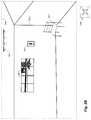
- FIG. 1Bdepicts a block diagram of an exemplary building interior environment in which 360° video is generated, for use by the VTFM system to generate and provide a corresponding building floor map, as discussed in greater detail with respect to FIGS. 2A-2O .
- FIG. 1Billustrates one story of a multi-story building 198 with an interior that was captured at least in part via a 360° video by a mobile visual data acquisition device 185 with video acquisition capabilities as it is moved through the building interior along travel path 115 .
- An embodiment of the VCA systemmay automatically perform or assist in the capturing of the video data representing the building interior, as well as to further analyze the captured video data to generate a floor map or other visual representation of the building interior.
- a mobile visual data acquisition devicemay include various hardware components, such as one or more camera lenses and corresponding image sensors, one or more other hardware sensors (e.g., a gyroscope, an accelerometer, a compass, etc., such as part of one or more IMUs, or inertial measurement units, of the mobile device; an altimeter; light detector; etc.), a GPS receiver, one or more hardware processors, memory, a display, a microphone, etc.
- the mobile devicemay not in at least some embodiments have access to or use equipment to measure the depth of objects in the building relative to a location of the mobile device, such that relationships of video capture locations to the surrounding structure of the building may be determined in part or in whole based on features in different frames/images, but without using any data from any such depth sensors.
- the mobile device and/or VCA systemmay not use such absolute directional information in at least some embodiments, such as to instead determine relative directions and distances without regard to actual geographical positions or directions in such embodiments.
- the mobile visual data acquisition device 185arrives at a first viewing location 210 A within a first room of the building interior (in this example, in a living room accessible via an external door 190 - 1 ), and initiates a video capture that begins with a portion of the building interior that is visible from that viewing location 210 A (e.g., some or all of the first room, and optionally small portions of one or more other adjacent or nearby rooms, such as through doors, halls, stairs or other connecting passages from the first room).
- the video capturemay be performed in various manners as discussed herein, and may include a number of objects or other features (e.g., structural details) that may be visible in images captured from a particular capture location—in the example of FIG.
- such objects or other features along the path 115may include the doorways 190 (including 190 - 1 and 190 - 3 ) and 197 (e.g., with swinging and/or sliding doors), windows 196 (including 196 - 1 , 196 - 2 , 196 - 3 and 196 - 4 ), corners or edges 195 (including corner 195 - 1 in the northwest corner of the building 198 , corner 195 - 2 in the northeast corner of the first room, corner 195 - 3 in the southwest corner of the first room, corner 195 - 4 at the northern edge of the inter-room passage between the first room and a hallway, etc.), furniture 191 - 193 (e.g., a couch 191 ; chairs 192 - 1 to 192 - 3 ; tables 193 - 1 and 193 - 2 ; etc.), pictures or paintings or televisions or other hanging objects 194 (such as 194 - 1 and 194 - 2 ) hung on walls, light fixtures,
- the usermay also optionally provide a textual or auditory identifier to be associated with one or more capture locations at which the mobile device is located, such as “living room” for the room including capture location 210 A, while in other embodiments the VTFM system may automatically generate such identifiers (e.g., by automatically analyzing video and/or other recorded information for a building to perform a corresponding automated determination, such as by using machine learning) or the VCA system may instead determine such identifiers or the identifiers may not be used.
- a textual or auditory identifierto be associated with one or more capture locations at which the mobile device is located, such as “living room” for the room including capture location 210 A
- the VTFM systemmay automatically generate such identifiers (e.g., by automatically analyzing video and/or other recorded information for a building to perform a corresponding automated determination, such as by using machine learning) or the VCA system may instead determine such identifiers or the identifiers may not be used.
- the mobile device 185may move or be moved along the path 115 throughout the building interior, recording video and optionally other data from the hardware components (e.g., from one or more IMUs, a light detector, etc.). This process may optionally continue external to the building, as illustrated for ending capture location 210 C in this example.
- the hardware componentse.g., from one or more IMUs, a light detector, etc.
- FIGS. 1A-1BVarious details are provided with respect to FIGS. 1A-1B , but it will be appreciated that the provided details are non-exclusive examples included for illustrative purposes, and other embodiments may be performed in other manners without some or all such details.
- FIGS. 2A-2Oillustrate examples of generating and presenting a floor map for a building using 360° video and/or other visual information of the building interior, such as for the building 198 and using video captured along the path 115 discussed in FIG. 1B .
- FIG. 2Aincludes information 255 a illustrating a portion of the house 198 of FIG. 1B , including the living room and portions of the further rooms to the east of the living room.
- informationis illustrated for a portion of the path 115 illustrated in FIG. 1B , and in particular illustrates a sequence of locations 215 along the path at which one or more video frame images are captured of the surrounding interior of the house—examples of such locations include capture locations 240 a - c , with further information related to video frame images captured from those locations shown in FIGS. 2B-2D .
- the locations 215 along the pathare shown as being separated by short distances (e.g., a foot, an inch, a fraction of an inch, etc.), although it will be appreciated that video capture may be substantially continuous—thus, in at least some embodiments, the selection of video frame images for an image group to be analyzed may include selecting images that are separated by such distances and/or that are separated by a short period of time between their capture (e.g., a second, a fraction of a second, multiple seconds, etc.). In other embodiments, video frame images may be selected for use in the image group based on other criteria, whether in addition to or instead of separation by distance and/or time.
- short distancese.g., a foot, an inch, a fraction of an inch, etc.
- FIG. 2Bcontinues the example of FIG. 2A , and illustrates an example image 250 b captured from capture location 240 b of FIG. 2A —the illustrated image is a perspective image taken in a northeasterly direction, such as a northeasterly facing subset view of a 360-degree frame taken from that viewing location during video capture along the path 115 (or may instead be captured directly as a perspective image)—the directional indicator 109 b is further displayed in this example to illustrate the northeasterly direction in which the image is taken.
- the illustrated imageis a perspective image taken in a northeasterly direction, such as a northeasterly facing subset view of a 360-degree frame taken from that viewing location during video capture along the path 115 (or may instead be captured directly as a perspective image)—the directional indicator 109 b is further displayed in this example to illustrate the northeasterly direction in which the image is taken.
- the displayed imageincludes various features that may be detected during subsequent automated analysis of the image, including built-in elements (e.g., light fixture 130 a ), furniture (e.g., chair 192 - 1 ), two windows 196 - 1 , a picture 194 - 1 hanging on the north wall of the living room, and multiple room borders (including horizontal borders between a visible portion of the north wall of the living room and the living room's ceiling and floor, horizontal borders between a visible portion of the east wall of the living room and the living room's ceiling and floor, and the vertical border 195 - 2 between the north and east walls.
- built-in elementse.g., light fixture 130 a
- furnituree.g., chair 192 - 1
- two windows 196 - 1e.g., a picture 194 - 1 hanging on the north wall of the living room
- multiple room bordersincluding horizontal borders between a visible portion of the north wall of the living room and the living room's ceiling and floor, horizontal borders between a visible portion of the
- FIGS. 2C and 2Dfurther continue the examples of FIGS. 2A-2B , and illustrate additional example perspective images 250 c and 250 d , respectively, that are captured at locations 240 a and 240 c of FIG. 2A , respectively.
- the imagesare taken in a northwesterly direction, including to capture the northwest corner 195 - 1 of the living room—in a manner similar to that of image 250 b of FIG. 2B , images 250 c and 250 d may each be subsets of larger 360° panorama image frames (e.g., consecutive frames, or frames separated by at most a specified amount of time) from captured video along the path 115 (or may instead be captured directly as perspective images).
- images 250 c and 250 dinclude various features that may be detected during subsequent automated analysis of the images, including light fixture 130 b , window 196 - 2 , multiple room borders (including horizontal borders between a visible portion of the north wall of the living room and the living room's ceiling and floor, horizontal borders between a visible portion of the west wall of the living room and the living room's ceiling and floor, and the vertical border 195 - 1 between the north and west walls, although no inter-room passages into or out of the living room (e.g., doors or other wall openings) are visible in these images.
- room bordersincluding horizontal borders between a visible portion of the north wall of the living room and the living room's ceiling and floor, horizontal borders between a visible portion of the west wall of the living room and the living room's ceiling and floor, and the vertical border 195 - 1 between the north and west walls, although no inter-room passages into or out of the living room (e.g., doors or other wall openings) are visible in these images.
- Images 250 c and 250 dillustrate that, since their capture locations 240 a and 240 c are close to each other, the contents of their images differ only in relatively small amounts, and thus images 250 c and 250 d share many features that may be identified in an automated analysis of the images but provide only limited information about differences in locations of those features between the images.
- image 250 dis modified in this example to illustrate visual indications 285 g of differences from corner 195 - 1 in image 250 d to the corner's location in image 250 c (as shown in dotted lines 262 in FIG. 2D for the purpose of comparison, but which would not otherwise be visible in image 250 d ).
- the capture location of 240 b for image 250 bdiffers significantly from capture locations 240 a and 240 c , but there may be little overlap in features between images captured from such capture locations if the images are perspective images in particular directions/orientations.
- various matching featuresmay be detected and used in each sub-group of two or more such images, as illustrated further with respect to FIGS. 2E-2J .
- FIGS. 2E-2Jcontinue the examples of FIGS. 2A-2D , and illustrate additional information about the living room and about analyzing 360° image frames from the video captured along the path 155 in order to determine the likely shape of the room.
- FIG. 2Eincludes information 255 e illustrating that a 360° image frame taken from location 240 b will share information about a variety of features with that of a 360° image frame taken from location 240 a , although such features are only illustrated in FIG. 2E for a portion of the living room for the sake of simplicity.
- FIG. 2Eincludes information 255 e illustrating that a 360° image frame taken from location 240 b will share information about a variety of features with that of a 360° image frame taken from location 240 a , although such features are only illustrated in FIG. 2E for a portion of the living room for the sake of simplicity.
- example lines of sight 228 from location 240 b to various example features in the roomare shown, and similar example lines of sight 227 from location 240 a to corresponding features are shown, which illustrate degrees of difference between the views at significantly spaced capture locations.
- analysis of the sequence of images in the image group corresponding to locations 215 of FIG. 2A using SLAM and/or MVS and/or SfM techniquesmay provide a variety of information about the features of the living room, including information about associated planes of the features and normal orthogonal directions from the planes, as illustrated further with respect to FIGS. 2F-2I .
- FIG. 2Fillustrates information 255 f about the northeast portion of the living room that is visible in subsets of 360° image frames taken from locations 240 a and 240 b
- FIG. 2Gillustrates information 255 g about the northwest portion of the living room that is visible in other subsets of 360° image frames taken from locations 240 a and 240 b , with various features in those portions of the living room being visible in both 360° image frames (e.g., corners 195 - 1 and 195 - 2 , windows 196 - 1 and 1962 , etc.
- information about planes 286 e and 286 f corresponding to portions of the northern wall of the living roommay be determined from the features that are detected, and information 287 e and 285 f about portions of the east and west walls of the living room may be similarly determined from corresponding features identified in the images.
- the SLAM and/or MVS and/or SfM techniquesmay further determine information about likely positions and orientations/directions 220 for the image(s) from capture location 240 a , and likely positions and orientations/directions 222 for the image(s) from capture location 240 b (e.g., positions 220 g and 222 g in FIG. 2F of the capture locations 240 a and 240 b , respectively, and optionally directions 220 e and 222 e for the image subsets shown in FIG. 2F ; and corresponding positions 220 g and 222 g in FIG.
- FIGS. 2F and 2GWhile only features for part of the living room are illustrated in FIGS. 2F and 2G , it will be appreciated that the other portions of the 360° image frames corresponding to other portions of the living room may be analyzed in a similar manner, in order to determine possible information about possible planes for the various walls of the room, as well as for other features (not shown) in the living room. In addition, similar analyses may be performed between some or all other images at locations 215 in the living room that are selected for use in the image group, resulting in a variety of determined feature planes from the various image analyses that may correspond to walls of the room.
- FIG. 2Hcontinues the examples of FIGS. 2A-2G , and illustrates information 255 h about a variety of determined feature planes that may correspond to the west and north walls of the living room, from analyses of the 360° image frames captured at locations 240 a and 240 b .
- the illustrated plane informationincludes determined planes 286 G near or at the northern wall (and thus corresponding possible locations of the northern wall), and determined planes 285 G near or at the western wall (and thus corresponding possible locations of the western wall).
- FIG. 2Hit will be appreciated that similar determined feature planes for the other walls of the living room would similarly be detected, along with determined feature planes corresponding to features that are not along the walls (e.g., furniture).
- FIG. 2Icontinues the examples of FIGS. 2A-2H , and illustrates information 255 i about additional determined feature planes that may correspond to the west and north walls of the living room, from analyses of various additional 360° image frames selected for the image group corresponding to example locations 240 along the path 115 in the living room—as would be expected, the analyses of the further images provides even greater variations in different determined planes for the northern and western walls.
- FIG. 2Ifurther illustrates additional determined information that is used to aggregate information about the various determined feature planes in order to identify likely locations 295 a and 295 b of the west and north walls, as illustrated in information 255 j of FIG. 2J .
- FIG. 2Ifurther illustrates additional determined information that is used to aggregate information about the various determined feature planes in order to identify likely locations 295 a and 295 b of the west and north walls, as illustrated in information 255 j of FIG. 2J .
- 2Iillustrates information 291 a about normal orthogonal directions for some of the determined feature planes corresponding to the west wall, along with additional information 290 a about those determined feature planes.
- the determined feature planesare clustered to represent hypothesized wall locations of the west wall, and the information about the hypothesized wall locations is combined to determine the likely wall location 295 a , such as by weighting information from the various clusters and/or the underlying determined feature planes.
- the hypothesized wall locations and/or normal informationis analyzed via use of machine learning techniques to determine the resulting likely wall location, optionally by further applying assumptions or other constraints (such as a 90° corner, as illustrated in information 282 of FIG.
- FIG. 2Jillustrates the resulting likely wall locations 295 a and 295 b for the west and north walls of the living room, respectively.
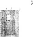
- FIG. 2Kcontinues the examples of FIGS. 2A-2J , and illustrates information 255 k about additional information that may be generated from images in an image group and used in one or more manners in at least some embodiments.
- video frames captured in the living room of the house 198may be analyzed in order to determine a 3D shape of the living room, such as from a 3D point cloud of features detected in the video frames (e.g., using SLAM and/or SfM and/or MVS techniques).
- information 255 kreflects an example portion of such a point cloud for the living room, such as in this example to correspond to a northwesterly portion of the living room (e.g., to include northwest corner 195 - 1 of the living room, as well as windows 196 - 1 ) in a manner similar to image 250 c of FIG. 2C .
- Such a point cloudmay be further analyzed to determine planar areas, such as to correspond to walls, the ceiling, floor, etc., as well as in some cases to detect features such as windows, doorways and other inter-room openings, etc.—in this example, a first planar area 298 corresponding to the north wall of the living room is identified, with a second planar area 299 corresponding to windows 196 - 1 being further identified. It will be appreciated that various other walls and other features may be similarity identified in the living room and in the other rooms of the house 198 .
- FIG. 2Lillustrates additional information 255 l corresponding to, after estimated room shapes are determined for the rooms of the illustrated floor of the house 198 , positioning the rooms' estimated room shapes relative to each other, based at least in part on connecting inter-room passages between rooms and matching room shape information between adjoining rooms—in at least some embodiments, such information may be treated as constraints on the positioning of the rooms, and an optimal or otherwise preferred solution is determined for those constraints. Examples of such constraints in FIG. 2L include matching 231 connecting passage information (e.g., passages detected in the automated image analyses discussed with respect to FIGS.
- House exterior information 239may further be identified and used as constraints (e.g., based at least in part of automated identification of passages and other features corresponding to the building exterior, such as windows), such as to prevent another room from being placed at a location that has been identified as the building's exterior.
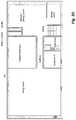
- FIGS. 2M-2Ocontinue the examples of FIGS. 2A-2L , and illustrate mapping information that may be generated from the types of analyses discussed in FIGS. 2A-2L .
- FIG. 2Millustrates an example floor map 230 m that may be constructed based on the positioning of the estimated room shapes, which in this example includes walls and indications of doors and windows.
- such a floor mapmay have further information shown, such as about other features that are automatically detected by the image analysis and/or that are subsequently added by one or more users.
- FIG. 2Nillustrates a modified floor map 230 n that includes additional information of various types, such as may be automatically identified from image analysis and added to the floor map 230 m , including one or more of the following types of information: room labels (e.g., “living room” for the living room), room dimensions, visual indications of fixtures or appliances or other built-in features, visual indications of positions of additional types of associated and linked information (e.g., of panorama images and/or perspective images that an end user may select for further display, of audio annotations and/or sound recordings that an end user may select for further presentation, etc.), visual indications of doors and windows, etc.—in other embodiments and situations, some or all such types of information may instead be provided by one or more VTFM system operator users and/or VCA system operator users.
- room labelse.g., “living room” for the living room
- room dimensionse.g., “living room” for the living room
- visual indications of fixtures or appliances or other built-in featurese.g., visual
- one or more user-selectable controlsmay be added to indicate a current floor that is displayed and/or to allow the end user to select a different floor to be displayed—in some embodiments, a change in floors or other levels may also be made directly from the displayed floor map, such as via selection of a corresponding connecting passage (e.g., stairs to a different floor). It will be appreciated that a variety of other types of information may be added in some embodiments, that some of the illustrated types of information may not be provided in some embodiments, and that visual indications of and user selections of linked and associated information may be displayed and selected in other manners in other embodiments.
- FIG. 2Ocontinues the examples of FIGS. 2A-2N , and Illustrates additional information 265 that may be generated from the automated analysis techniques disclosed herein, which in this example is a 2.5D or 3D model of the floor of the house.
- a model 265may be additional mapping-related information that is generated based on the floor map 230 m or 230 n , but with additional information about height shown in order to illustrate visual locations in walls of features such as windows and doors.
- additional informationmay be added to the displayed walls in some embodiments, such as from images taken during the video capture (e.g., to illustrate actual paint, wallpaper or other surfaces from the house on the rendered model 265 ).
- FIGS. 2A-2OVarious details have been provided with respect to FIGS. 2A-2O , but it will be appreciated that the provided details are non-exclusive examples included for illustrative purposes, and other embodiments may be performed in other manners without some or all such details.
- FIG. 3is a block diagram illustrating an embodiment of one or more server computing systems 300 executing an implementation of a VTFM system 340 , and one or more server computing systems 380 executing an implementation of a VCA system 389 —the server computing system(s) and VTFM and/or VCA systems may be implemented using a plurality of hardware components that form electronic circuits suitable for and configured to, when in combined operation, perform at least some of the techniques described herein.
- each server computing system 300includes one or more hardware central processing units (“CPUs”) or other hardware processors 305 , various input/output (“I/O”) components 310 , storage 320 , and memory 330 , with the illustrated I/O components including a display 311 , a network connection 312 , a computer-readable media drive 313 , and other I/O devices 315 (e.g., keyboards, mice or other pointing devices, microphones, speakers, GPS receivers, etc.).
- Each server computing system 380may have similar components, although only one or more hardware processors 381 , memory 387 , storage 385 and I/O components 382 are illustrated in this example for the sake of brevity.
- the server computing system(s) 300 and executing VTFM system 340 , and server computing system(s) 380 and executing VCA system 389may communicate with each other and with other computing systems and devices in this illustrated embodiment via one or more networks 399 (e.g., the Internet, one or more cellular telephone networks, etc.), such as to interact with user client computing devices 390 (e.g., used to view floor maps, and optionally associated images and/or other related information), and/or mobile visual data acquisition devices 360 (e.g., used to acquire video and optionally additional images and/or other information for buildings or other environments to be modeled), and/or optionally other navigable devices 395 that receive and use floor maps and optionally other generated information for navigation purposes (e.g., for use by semi-autonomous or fully autonomous vehicles or other devices).
- networks 399e.g., the Internet, one or more cellular telephone networks, etc.
- user client computing devices 390e.g., used to view floor maps, and optionally associated images and/or other
- some of the described functionalitymay be combined in less computing systems, such as to combine the VTFM system 340 and the visual data acquisition functionality of device(s) 360 in a single system or device, to combine the VCA system 389 and the visual data acquisition functionality of device(s) 360 in a single system or device, to combine the VTFM system 340 and the VCA system 389 in a single system or device, to combine the VTFM system 340 and the VCA system 389 and the visual data acquisition functionality of device(s) 360 in a single system or device, etc.
- an embodiment of the VTFM system 340executes in memory 330 of the server computing system(s) 300 in order to perform at least some of the described techniques, such as by using the processor(s) 305 to execute software instructions of the system 340 in a manner that configures the processor(s) 305 and computing system 300 to perform automated operations that implement those described techniques.
- the illustrated embodiment of the VTFM systemmay include one or more components, not shown, to each perform portions of the functionality of the VTFM system, and the memory may further optionally execute one or more other programs 335 —as one specific example, a copy of the VCA system may execute as one of the other programs 335 in at least some embodiments, such as instead of or in addition to the VCA system 389 on the server computing system(s) 380 .
- the VTFM system 340may further, during its operation, store and/or retrieve various types of data on storage 320 (e.g., in one or more databases or other data structures), such as various types of user information 322 , acquired video and/or image information 324 (e.g., 360° video or images received from VCA system 389 , such as for analysis to generate floor maps, to provide to users of client computing devices 390 for display, etc.), optionally generated floor maps and other associated information 326 (e.g., generated and saved 2.5D and/or 3D models, building and room dimensions for use with associated floor maps, additional images and/or annotation information, etc.) and/or various types of optional additional information 328 (e.g., various analytical information related to presentation or other use of one or more building interiors or other environments).
- various types of user information 322e.g., acquired video and/or image information 324 (e.g., 360° video or images received from VCA system 389 , such as for analysis to generate floor maps, to provide to users of
- an embodiment of the VCA system 389executes in memory 387 of the server computing system(s) 380 in the illustrated embodiment in order to perform at least some of the described techniques, such as by using the processor(s) 381 to execute software instructions of the system 389 in a manner that configures the processor(s) 381 and computing system 380 to perform automated operations that implement those described techniques.
- the illustrated embodiment of the VCA systemmay include one or more components, not shown, to each perform portions of the functionality of the VCA system, and the memory may further optionally execute one or more other programs (not shown).
- the VCA system 389may further, during its operation, store and/or retrieve various types of data on storage 385 (e.g., in one or more databases or other data structures), such as video and/or image information 386 acquired for one or more buildings, building and room dimensions for use with associated floor maps, additional images and/or annotation information, various analytical information related to presentation or other use of one or more building interiors or other environments, etc.—while not illustrated in FIG.
- the VCA systemmay further store and use additional types of information, such as about other types of building information to be analyzed and/or provided to the VTFM system (e.g., building and room dimensions for use with associated floor maps, additional images and/or annotation information, various analytical information related to presentation or other use of one or more building interiors or other environments, etc.), about VCA system operator users, etc.
- additional types of informationsuch as about other types of building information to be analyzed and/or provided to the VTFM system (e.g., building and room dimensions for use with associated floor maps, additional images and/or annotation information, various analytical information related to presentation or other use of one or more building interiors or other environments, etc.), about VCA system operator users, etc.
- the mobile visual data acquisition devices 360are each shown to include one or more hardware CPU(s) 361 , I/O components 362 , storage 365 , and memory 367 , with one or both of a browser and one or more client applications 368 (e.g., an application specific to the VTFM system and/or VCA system) executing within memory 367 , such as to participate in communication with the VTFM system 340 , VCA system 389 and/or other computing systems—the devices 360 each further include one or more imaging systems 364 and IMU hardware sensors 369 , such as for use in acquisition of video and/or images, associated device movement data, etc. While particular components are not illustrated for the other navigable devices 395 or other computing systems 390 , it will be appreciated
- computing systems 300 and 380 and the other systems and devices included within FIG. 3are merely illustrative and are not intended to limit the scope of the present invention.
- the systems and/or devicesmay instead each include multiple interacting computing systems or devices, and may be connected to other devices that are not specifically illustrated, including via Bluetooth communication or other direct communication, through one or more networks such as the Internet, via the Web, or via one or more private networks (e.g., mobile communication networks, etc.).
- a device or other computing systemmay comprise any combination of hardware that may interact and perform the described types of functionality, optionally when programmed or otherwise configured with particular software instructions and/or data structures, including without limitation desktop or other computers (e.g., tablets, slates, etc.), database servers, network storage devices and other network devices, smart phones and other cell phones, consumer electronics, wearable devices, digital music player devices, handheld gaming devices, PDAs, wireless phones, Internet appliances, and various other consumer products that include appropriate communication capabilities.
- the functionality provided by the illustrated VTFM system 340 and/or VCA system 389may in some embodiments be distributed in various components, some of the described functionality of the VTFM system 340 and/or VCA system 389 may not be provided, and/or other additional functionality may be provided.
- some or all of the described techniquesmay be performed by hardware means that include one or more processors and/or memory and/or storage when configured by one or more software programs (e.g., by the VTFM system 340 executing on server computing systems 300 and/or on devices 360 , by the VCA software 389 executing on server computing systems 380 , etc.) and/or data structures, such as by execution of software instructions of the one or more software programs and/or by storage of such software instructions and/or data structures, and such as to perform algorithms as described in the flow charts and other disclosure herein.
- software programse.g., by the VTFM system 340 executing on server computing systems 300 and/or on devices 360 , by the VCA software 389 executing on server computing systems 380 , etc.
- data structuressuch as by execution of software instructions of the one or more software programs and/or by storage of such software instructions and/or data structures, and such as to perform algorithms as described in the flow charts and other disclosure herein.
- some or all of the systems and/or componentsmay be implemented or provided in other manners, such as by consisting of one or more means that are implemented partially or fully in firmware and/or hardware (e.g., rather than as a means implemented in whole or in part by software instructions that configure a particular CPU or other processor), including, but not limited to, one or more application-specific integrated circuits (ASICs), standard integrated circuits, controllers (e.g., by executing appropriate instructions, and including microcontrollers and/or embedded controllers), field-programmable gate arrays (FPGAs), complex programmable logic devices (CPLDs), etc.
- ASICsapplication-specific integrated circuits
- controllerse.g., by executing appropriate instructions, and including microcontrollers and/or embedded controllers
- FPGAsfield-programmable gate arrays
- CPLDscomplex programmable logic devices
- Non-transitory computer-readable storage mediumssuch as a hard disk or flash drive or other non-volatile storage device, volatile or non-volatile memory (e.g., RAM or flash RAM), a network storage device, or a portable media article (e.g., a DVD disk, a CD disk, an optical disk, a flash memory device, etc.) to be read by an appropriate drive or via an appropriate connection.
- a non-transitory computer-readable storage mediumssuch as a hard disk or flash drive or other non-volatile storage device, volatile or non-volatile memory (e.g., RAM or flash RAM), a network storage device, or a portable media article (e.g., a DVD disk, a CD disk, an optical disk, a flash memory device, etc.) to be read by an appropriate drive or via an appropriate connection.
- the systems, components and data structuresmay also in some embodiments be transmitted via generated data signals (e.g., as part of a carrier wave or other analog or digital propagated signal) on a variety of computer-readable transmission mediums, including wireless-based and wired/cable-based mediums, and may take a variety of forms (e.g., as part of a single or multiplexed analog signal, or as multiple discrete digital packets or frames).
- generated data signalse.g., as part of a carrier wave or other analog or digital propagated signal
- Such computer program productsmay also take other forms in other embodiments. Accordingly, embodiments of the present disclosure may be practiced with other computer system configurations.
- FIG. 4illustrates an example flow diagram of an embodiment of a VCA System routine 400 .
- the routinemay be performed by, for example, the VCA system 160 of FIG. 1A , the VCA system 389 of FIG. 3 , and/or the VCA system described with respect to FIGS. 1A-2O and as otherwise described herein, such as to acquire video (e.g., continuous 360° video) and optionally other images at locations within buildings or other structures, such as for use in subsequent generation of related floor maps and/or other mapping information. While portions of the example routine 400 are discussed with respect to acquiring particular types of video at particular locations, it will be appreciated that this or a similar routine may be used to acquire images and/or other data (e.g., audio), whether instead of or in addition to such video.
- images and/or other datae.g., audio
- the illustrated embodimentacquires and uses information from the interior of a target building
- other embodimentsmay perform similar techniques for other types of data, including for non-building structures and/or for information external to one or more target buildings of interest.
- some or all of the routinemay be executed on a mobile device used by a user to acquire video and/or image information, and/or by a system remote from such a mobile device.
- the illustrated embodiment of the routinebegins at block 405 , where instructions or information are received.
- the routinedetermines whether the received instructions or information indicate to acquire data representing a building interior, and if not continues to block 490 . Otherwise, the routine proceeds to block 412 to receive an indication from a user of a mobile visual data acquisition device to begin the visual data acquisition process at a beginning capture location.
- the routineproceeds to block 415 in order to perform visual data acquisition activities starting at the beginning capture location and continuing along a path through at least some of the building, in order to acquire video (e.g., continuous 360° video, with horizontal coverage of at least 360° around a vertical axis for each video frame/image) of the interior of the target building of interest, such as via one or more fisheye lenses on the mobile device.
- the mobile visual data acquisition devicemay include one or more lens that together provide simultaneous 360° horizontal coverage, while as another non-exclusive example, the mobile visual data acquisition device may be a rotating (scanning) panorama camera equipped with a fisheye lens, such as a 180° fisheye giving a full sphere at 360° rotation.
- the routinemay also optionally obtain annotation and/or other information from the user regarding particular locations and/or the surrounding environment more generally (e.g., a current room), such as for later use in presentation of information regarding that location and/or surrounding environment.
- routinecontinues to block 420 to determine if there are more area at which to acquire images, such as based on corresponding information provided by the user of the mobile device. If so, and when the user is ready to continue the process, the routine continues to block 422 to determine that the acquisition device is ready at the next beginning capture location for further visual data acquisition (e.g., based on an indication from the user), and then continues to block 415 to perform a corresponding acquisition of further video (or of other image sequences).
- the mobile devicemay further capture additional information during some or all of the travel along the path through the building, such as additional sensor data (e.g., from one or more IMU, or inertial measurement units, on the mobile device or otherwise carried by the user), additional image information, recorded ambient sounds, recorded user verbal and/or textual annotations or other descriptions, ambient light levels, etc. for later use in presentation of information regarding that travel path or a resulting generated floor map and/or other mapping related information.
- the routinemay further optionally provide one or more guidance cues to the user regarding the motion of the mobile device, quality of the sensor data and/or video information being captured, associated lighting/environmental conditions, and any other suitable aspects of capturing the building interior information.
- the routineproceeds to block 425 to optionally analyze the acquired information for the building or other structure, such as to identify possible additional coverage (and/or other information) to acquire within the building interior.
- the VCA systemmay provide one or more notifications to the user regarding the information acquired during capture, such as if it determines that one or more segments of the recorded information are of insufficient or undesirable quality, or do not appear to provide complete coverage of the building.
- the routinecontinues to block 435 to optionally preprocess the acquired video information (and optionally other associated information) before its subsequent use for generating related mapping information.
- the video and any associated generated or obtained informationis stored for later use.
- FIGS. 5A-5Billustrate one example of a routine for generating a floor map representation of a building interior from the acquired video information.
- routinecontinues instead to block 490 to perform any other indicated operations as appropriate, such as any housekeeping tasks, to configure parameters to be used in various operations of the system (e.g., based at least in part on information specified by a user of the system, such as a user of a mobile device who captures one or more building interiors, an operator user of the VCA system, etc.), to obtain and store other information about users of the system, to respond to requests for generated and stored information, etc.
- any other indicated operationsas appropriate, such as any housekeeping tasks, to configure parameters to be used in various operations of the system (e.g., based at least in part on information specified by a user of the system, such as a user of a mobile device who captures one or more building interiors, an operator user of the VCA system, etc.), to obtain and store other information about users of the system, to respond to requests for generated and stored information, etc.
- routineproceeds to block 495 to determine whether to continue, such as until an explicit indication to terminate is received, or instead only if an explicit indication to continue is received. If it is determined to continue, the routine returns to block 405 to await additional instructions or information, and if not proceeds to step 499 and ends.
- FIGS. 5A-5Billustrate an example embodiment of a flow diagram for a Visual data-To-Floor Map (VTFM) System routine 500 .
- the routinemay be performed by, for example, execution of the VTFM system 140 of FIG. 1A , the VTFM system 340 of FIG. 3 , and/or an VTFM system as described with respect to FIGS. 1A-2O and elsewhere herein, such as to generate mapping information for a defined area based at least in part on analysis of video (e.g., 360° video with frames that are each 360° spherical panorama images) of the area.
- videoe.g., 360° video with frames that are each 360° spherical panorama images
- the generated mapping informationincludes a floor map of a building (e.g., a house), but in other embodiments, other types of mapping information may be generated for other types of buildings and used in other manners, as discussed elsewhere herein.
- FIGS. 5A-5Banalyzes frames from continuous video on a path through the building, other types of sequences of images may be used in other embodiments, as discussed elsewhere herein.
- the routine 500begins at step 505 , where information or instructions are received, and continues to block 510 to determine whether the instructions received in block 505 are to generate a floor map for an indicated building. If not, the routine proceeds to block 590 , and otherwise continues to perform blocks 520 - 585 as part of the floor map generation process. In particular, in block 520 , the routine obtains one or more videos (or other sequences of images) taken in rooms of the building (e.g., along a path taken through the building), such as by receiving the video(s) in block 505 or retrieving previously stored videos for the indicated building.
- the routinecontinues to block 525 to determine an image group that include some or all of the video frames (or other images from the sequence) to use as images for the subsequent room shape determination analysis, including in some cases to use portions of 360° image frames in particular directions/orientations (or other images that have less than 360° of horizontal coverage) as images in the image group, while in other cases entire 360° image frames are used as images in the image group.
- the routineperforms a loop of blocks 530 - 553 for each room in the building to analyze the images in that room and to determine a corresponding estimated room shape for the room.
- the routine in block 530selects a next room from the building, beginning with the first, and select images from the image group that were taken in the room.
- the routinethen performs an image analysis of the selected images to detect structural features in the room, and analyzes information about the detected features to determine normal (orthogonal) directions for the detected features and to identify corresponding planar surfaces on which the detected features are located.
- the routinethen, for each of the selected images, combines the determined normal direction information for that image to determine corresponding wall location hypotheses based on that image, such as by generating aggregate normal and planar surface information from the individual feature normal directions and planar surface information by using a weighted combination or in another manner, and optionally determines other structural features in the room that are visible from the image.
- the routinethen proceeds to cluster and optimize the wall location hypotheses from the multiple images that were analyzed in order to determine likely wall locations for the room, and then combines the determined estimated wall locations to generate an estimated room shape for the room.
- the combining of estimated wall locations to generate a room shapemay use various constraints (e.g., 90° corners, flat walls, etc.).
- the routinecontinues to block 538 to determine whether to perform a consistency analysis for the room shape information estimated from the clustered and aggregated normal direction information and planar surface information, such as by estimating room shape information in a different manner and comparing the information from the different techniques. If not, the routine continues to block 540 to select the estimated room shape from block 536 as the likely room shape for the room, and otherwise proceeds to perform blocks 542 - 552 as part of the multi-view consistency analysis.
- the routine in block 542generates a 3D point cloud for the room from the various selected images for the room, such as by using one or more of a SLAM analysis, SfM analysis or MVS analysis, including to localize each selected image in space and to determine the orientation/direction of the image/camera if other than a 360° image.
- the routinethen analyzes the 3D point cloud information to determine a second set of likely wall locations in the 3D point cloud, such as by grouping points that have a similar distance from the camera location and/or are within a threshold amount of a common planar surface, and then uses the determined second set of likely wall locations to generate a second estimated room shape for the room.
- the routinecompares the information and about the two sets of likely wall locations for the room to determine differences, including in some embodiments to optionally perform a multi-view consistency analysis by projecting expected pixel locations for one or more first selected images from one of the sets of likely wall locations to the likely wall locations of the other set for one or more second selected images, and by measuring an amount of reprojection error.
- the routinedetermines in block 548 if the differences exceed a defined threshold, and if so proceeds to block 550 to optionally reduce those differences via further automated analyses, although in other embodiments such further automated analyses may not be performed and the room may instead proceed directly to block 552 after block 546 .
- the routinemay, for example, initiate further image capture and/or analysis (e.g., by selecting and analyzing further images that were previously or currently captured) to improve one or both types of estimated room shapes, and/or may provide a notification of the differences and optionally receive and use further information from one or more system operator users of the VTFM system. While not illustrated in this example embodiment, in other embodiments one or both sets of likely wall locations and/or one or both estimated room shapes may be excluded from further uses if the differences exceed the threshold and are not reduced within it.
- the routinecontinues to block 552 to determine a likely room shape to use for the room from the two estimated room shapes, such as by combining the information for the two room shapes, or by selecting one of the two room shapes to use (e.g., dynamically based on error or uncertainty information for the two room shapes and/or two sets of likely wall locations, using a predetermined priority for one of the types of techniques for estimating room shape, etc.).
- the routinecontinues to block 553 to receive and store the room's estimated room shape for subsequent use, and then to block 555 to determine whether there are more rooms in the building having images to analyze, in which case the routine returns to block 530 to analyze the images for the next room in the building.
- the routinecontinues instead to block 580 to connect and align the room shapes for the various rooms to form a floor map of the building, such as by connecting inter-room passages and applying other constraints regarding room shape placement.
- one or more of the estimated room shapesmay be further adjusted, such as to reflect an overall fit between rooms and/or for the entire house, and additional processing to connect multiple floors of the building may be further performed if appropriate.
- other types of mapping-related informationmay be similarly generated, such as to add height location to the generated 2D floor map in order to generate a 3D or 2.5D floor map for the building.
- routinecontinues to block 585 to store and/or otherwise use the generated floor map and any other generated mapping-related information, including to optionally provide some or all of the generated mapping-related information to one or more recipients (e.g., in response to previous requests).
- routinecontinues instead to block 590 to perform one or more other indicated operations as appropriate.
- Such other indicated operationsmay include, for example, receiving additional information about a building to use in a later generation of a floor map for it, to receive and store additional information to associate with an already generated floor map (e.g., additional pictures, dimensions information, etc.), to provide requested information that was previously generated, to obtain and store other information about users of the system, to obtain and store information about requests from potential recipients of generated mapping related information to provide that information when it becomes available, etc.
- routinecontinues to block 595 to determine whether to continue, such as until an explicit indication to terminate is received. If it is determined to continue, the routine returns to block 505 , and otherwise continues to block 599 and ends.
- FIG. 6illustrates an example embodiment of a flow diagram for a Building Map Viewer system routine 600 .
- the routinemay be performed by, for example, execution of a map viewer client computing device 175 and its software system(s) (not shown) of FIG. 1A , a client computing device 390 of FIG. 3 , and/or a mapping information viewer or presentation system as described elsewhere herein, such as to receive and display mapping information (e.g., a floor map, whether 2D, 3D, 2.5D or other format) for a defined area, including in some situations to display additional information (e.g., images, such as 360° spherical panorama images) associated with particular locations in the mapping information.
- mapping informatione.g., a floor map, whether 2D, 3D, 2.5D or other format
- additional informatione.g., images, such as 360° spherical panorama images
- the presented mapping informationis based on a floor map of a building (such as a house) that may optionally have additional associated linked information (e.g., images taken within the building, sounds recorded within the building, annotations or other descriptive information associated with particular locations within the building, etc.), but in other embodiments, other types of mapping information may be presented for other types of buildings or environments and used in other manners, as discussed elsewhere herein.
- a floor map of a buildingsuch as a house
- additional associated linked informatione.g., images taken within the building, sounds recorded within the building, annotations or other descriptive information associated with particular locations within the building, etc.
- the illustrated embodiment of the routinebegins at block 605 , where instructions or information are received.
- the routinedetermines whether the received instructions or information indicate to display or otherwise present information representing a building interior, and if not continues to block 690 . Otherwise, the routine proceeds to block 612 to retrieve a floor map for the building and optionally indications of associated linked information for the floor map and/or a surrounding location, and selects an initial view of the retrieved information (e.g., a view of the floor map).
- the routinedisplays or otherwise presents the current view of the retrieved information, and waits in block 617 for a user selection or other event (e.g., receiving updated information corresponding to the current view, an expiration of a timer, etc.).
- the routinecontinues to block 622 to update the current view in accordance with the user selection, and then returns to block 615 to update the displayed or otherwise presented information accordingly.
- the user selection and corresponding updating of the current viewmay include, for example, displaying or otherwise presenting a piece of associated linked information that the user selects (e.g., a particular image), changing how the current view is displayed (e.g., zooming in or out, rotating information if appropriate, selecting a new portion of the current view to be displayed or otherwise presented that was not previously visible, etc.).
- routinecontinues instead to block 690 to perform any other indicated operations as appropriate, such as any housekeeping tasks, to configure parameters to be used in various operations of the system (e.g., based at least in part on information specified by a user of the system, such as a user of a mobile device who captures one or more building interiors, an operator user of the VTFM system, etc.), to obtain and store other information about users of the system, to respond to requests for generated and stored information, etc.
- any other indicated operationsas appropriate, such as any housekeeping tasks, to configure parameters to be used in various operations of the system (e.g., based at least in part on information specified by a user of the system, such as a user of a mobile device who captures one or more building interiors, an operator user of the VTFM system, etc.), to obtain and store other information about users of the system, to respond to requests for generated and stored information, etc.
- the routineproceeds to block 695 to determine whether to continue, such as until an explicit indication to terminate is received, or instead only if an explicit indication to terminate is received. If it is determined to continue (e.g., if the user made a selection in block 617 related to a new location to present), the routine returns to block 605 to await additional instructions or information (or to continue on to block 612 if the user made a selection in block 617 related to a new location to present), and if not proceeds to step 699 and ends.
- any data structures discussed abovemay also be structured in different manners, such as by having a single data structure split into multiple data structures and/or by having multiple data structures consolidated into a single data structure.
- illustrated data structuresmay store more or less information than is described, such as when other illustrated data structures instead lack or include such information respectively, or when the amount or types of information that is stored is altered.
Landscapes
- Engineering & Computer Science (AREA)
- Remote Sensing (AREA)
- Radar, Positioning & Navigation (AREA)
- Physics & Mathematics (AREA)
- General Physics & Mathematics (AREA)
- Theoretical Computer Science (AREA)
- Automation & Control Theory (AREA)
- Computer Vision & Pattern Recognition (AREA)
- Computer Graphics (AREA)
- Geometry (AREA)
- Signal Processing (AREA)
- Multimedia (AREA)
- Software Systems (AREA)
- Processing Or Creating Images (AREA)
Abstract
Description
Claims (31)
Priority Applications (2)
| Application Number | Priority Date | Filing Date | Title |
|---|---|---|---|
| US17/080,604US11164361B2 (en) | 2019-10-28 | 2020-10-26 | Generating floor maps for buildings from automated analysis of visual data of the buildings' interiors |
| US17/493,701US11494973B2 (en) | 2019-10-28 | 2021-10-04 | Generating floor maps for buildings from automated analysis of visual data of the buildings' interiors |
Applications Claiming Priority (2)
| Application Number | Priority Date | Filing Date | Title |
|---|---|---|---|
| US201962927032P | 2019-10-28 | 2019-10-28 | |
| US17/080,604US11164361B2 (en) | 2019-10-28 | 2020-10-26 | Generating floor maps for buildings from automated analysis of visual data of the buildings' interiors |
Related Child Applications (1)
| Application Number | Title | Priority Date | Filing Date |
|---|---|---|---|
| US17/493,701ContinuationUS11494973B2 (en) | 2019-10-28 | 2021-10-04 | Generating floor maps for buildings from automated analysis of visual data of the buildings' interiors |
Publications (2)
| Publication Number | Publication Date |
|---|---|
| US20210125397A1 US20210125397A1 (en) | 2021-04-29 |
| US11164361B2true US11164361B2 (en) | 2021-11-02 |
Family
ID=75585958
Family Applications (2)
| Application Number | Title | Priority Date | Filing Date |
|---|---|---|---|
| US17/080,604ActiveUS11164361B2 (en) | 2019-10-28 | 2020-10-26 | Generating floor maps for buildings from automated analysis of visual data of the buildings' interiors |
| US17/493,701ActiveUS11494973B2 (en) | 2019-10-28 | 2021-10-04 | Generating floor maps for buildings from automated analysis of visual data of the buildings' interiors |
Family Applications After (1)
| Application Number | Title | Priority Date | Filing Date |
|---|---|---|---|
| US17/493,701ActiveUS11494973B2 (en) | 2019-10-28 | 2021-10-04 | Generating floor maps for buildings from automated analysis of visual data of the buildings' interiors |
Country Status (2)
| Country | Link |
|---|---|
| US (2) | US11164361B2 (en) |
| CA (1) | CA3097164C (en) |
Cited By (15)
| Publication number | Priority date | Publication date | Assignee | Title |
|---|---|---|---|---|
| US20220343612A1 (en)* | 2019-11-18 | 2022-10-27 | Magic Leap, Inc. | Mapping and localization of a passable world |
| US11645781B2 (en) | 2020-11-23 | 2023-05-09 | MFTB Holdco, Inc. | Automated determination of acquisition locations of acquired building images based on determined surrounding room data |
| US11676344B2 (en) | 2019-11-12 | 2023-06-13 | MFTB Holdco, Inc. | Presenting building information using building models |
| US11790648B2 (en) | 2021-02-25 | 2023-10-17 | MFTB Holdco, Inc. | Automated usability assessment of buildings using visual data of captured in-room images |
| US11830135B1 (en) | 2022-07-13 | 2023-11-28 | MFTB Holdco, Inc. | Automated building identification using floor plans and acquired building images |
| US11836973B2 (en) | 2021-02-25 | 2023-12-05 | MFTB Holdco, Inc. | Automated direction of capturing in-room information for use in usability assessment of buildings |
| US11842464B2 (en) | 2021-09-22 | 2023-12-12 | MFTB Holdco, Inc. | Automated exchange and use of attribute information between building images of multiple types |
| US20240036791A1 (en)* | 2022-07-27 | 2024-02-01 | Yoshikazu GYOBU | Information processing apparatus, information processing method, and non-transitory recording medium |
| US12045951B2 (en) | 2021-12-28 | 2024-07-23 | MFTB Holdco, Inc. | Automated building information determination using inter-image analysis of multiple building images |
| US12056900B2 (en) | 2021-08-27 | 2024-08-06 | MFTB Holdco, Inc. | Automated mapping information generation from analysis of building photos |
| US12175562B2 (en) | 2022-11-11 | 2024-12-24 | MFTB Holdco, Inc. | Automated inter-image analysis of multiple building images for building information determination |
| US12260156B2 (en) | 2022-07-25 | 2025-03-25 | MFTB Holdco, Inc. | Automated tools for incremental generation of building mapping information |
| US12333655B2 (en) | 2019-11-12 | 2025-06-17 | MFTB Holdco, Inc. | Presenting building information using video and building models |
| US12347033B1 (en) | 2022-11-11 | 2025-07-01 | MFTB Holdco, Inc. | Automated inter-image analysis of multiple building images for building floor plan generation |
| US12444139B2 (en) | 2022-09-22 | 2025-10-14 | MFTB Holdco, Inc. | Automated generation and presentation of visual data enhancements on camera view images captured in a building |
Families Citing this family (33)
| Publication number | Priority date | Publication date | Assignee | Title |
|---|---|---|---|---|
| WO2019205069A1 (en)* | 2018-04-27 | 2019-10-31 | Beijing Didi Infinity Technology And Development Co., Ltd. | Systems and methods for updating 3d model of building |
| FR3098211B1 (en)* | 2019-07-03 | 2024-12-13 | Airbus Operations Sas | CABLE PHOTOGRAMMETRIC ROBOT |
| US12014120B2 (en)* | 2019-08-28 | 2024-06-18 | MFTB Holdco, Inc. | Automated tools for generating mapping information for buildings |
| JP7611648B2 (en)* | 2020-03-05 | 2025-01-10 | 株式会社トプコン | Information processing device, inference model construction method, program, and recording medium |
| US11877159B2 (en)* | 2020-06-16 | 2024-01-16 | Microsoft Technology Licensing, Llc | Computing system that is configured to assign wireless beacons to positions within a building |
| EP4229552B1 (en)* | 2020-10-13 | 2025-04-23 | LexisNexis Risk Solutions FL Inc. | Generating measurements of physical structures and environments through automated analysis of sensor data |
| US11551370B2 (en)* | 2020-12-18 | 2023-01-10 | Nationwide Management Services, Inc. | Remote inspection and appraisal of buildings |
| US20220207202A1 (en)* | 2020-12-29 | 2022-06-30 | OPAL AI Inc. | Systems And Methods To Generate A Floorplan Of A Building |
| CN112860826B (en)* | 2021-01-15 | 2024-09-06 | 北京小米移动软件有限公司 | Function control method, function control device and storage medium |
| US11683462B2 (en) | 2021-06-04 | 2023-06-20 | Dierks Technology, Inc. | Matching segments of video for virtual display of a space |
| US11501492B1 (en)* | 2021-07-27 | 2022-11-15 | Zillow, Inc. | Automated room shape determination using visual data of multiple captured in-room images |
| GB2612051B (en)* | 2021-10-20 | 2024-04-10 | Sony Interactive Entertainment Inc | Apparatus and method for localisation and mapping |
| US20230125295A1 (en)* | 2021-10-22 | 2023-04-27 | MFTB Holdco, Inc. | Automated Analysis Of Visual Data Of Images To Determine The Images' Acquisition Locations On Building Floor Plans |
| US20230138762A1 (en)* | 2021-10-28 | 2023-05-04 | MFTB Holdco, Inc. | Automated Building Floor Plan Generation Using Visual Data Of Multiple Building Images |
| US12271967B2 (en) | 2021-11-19 | 2025-04-08 | R.E. Data Lab, Inc. | Comparative searching in a real estate search engine |
| CN114189697B (en)* | 2021-12-03 | 2022-10-14 | 腾讯科技(深圳)有限公司 | Video data processing method and device and readable storage medium |
| DE102022131567A1 (en)* | 2021-12-08 | 2023-06-15 | Dräger Safety AG & Co. KGaA | Method and system for determining a floor plan |
| CN114339609B (en)* | 2021-12-23 | 2023-06-13 | 浙江中控技术股份有限公司 | Personnel positioning method and device |
| CN114359440A (en)* | 2021-12-29 | 2022-04-15 | 武汉中地数码科技有限公司 | Method, computer equipment and storage medium for automatically generating road route indoors |
| US20230245390A1 (en)* | 2022-02-02 | 2023-08-03 | Tencent America LLC | Manhattan layout estimation using geometric and semantic information |
| US12093615B2 (en)* | 2022-05-05 | 2024-09-17 | D.To, Inc. | Apparatus and methods for determining and solving design problems using machine learning |
| US20230409766A1 (en)* | 2022-06-16 | 2023-12-21 | MFTB Holdco, Inc. | Automated Tools For Assessing Building Mapping Information Generation |
| US12221119B2 (en)* | 2022-07-12 | 2025-02-11 | Gm Cruise Holdings Llc | Drive-through calibration process |
| DE102022126640A1 (en)* | 2022-10-13 | 2024-04-18 | Dräger Safety AG & Co. KGaA | Method and device for generating a floor plan of a building |
| WO2024096819A1 (en)* | 2022-11-02 | 2024-05-10 | National University Of Singapore | System and method for map building and map- and image-based object control |
| TWI831495B (en)* | 2022-12-01 | 2024-02-01 | 財團法人工業技術研究院 | Positioning system and positioning method |
| US20240233260A1 (en)* | 2023-01-05 | 2024-07-11 | MFTB Holdco, Inc. | Automated Localization Using Beacon Transmitter Devices Of Data Acquired In Buildings |
| CN116188687A (en)* | 2023-02-02 | 2023-05-30 | 浙江工商大学 | Design system and method of human settlements based on digitization |
| JP2024153199A (en)* | 2023-04-17 | 2024-10-29 | パナソニックIpマネジメント株式会社 | Drawing preparation device and drawing preparation method |
| USD1087124S1 (en)* | 2023-07-07 | 2025-08-05 | CalmWave, Inc. | Display screen or portion thereof with a transitional graphical user interface |
| AU2024200714A1 (en)* | 2023-11-14 | 2025-05-29 | MFTB Holdco, Inc. | Automated generation and use of building videos based on analysis of building floor plan information |
| US20250209742A1 (en)* | 2023-12-21 | 2025-06-26 | Fnv Ip B.V. | Systems and methods for emergency response mapping and visualization in three dimensions using orthographic projection information |
| US12229884B1 (en) | 2024-02-15 | 2025-02-18 | Hong Kong Applied Science and Technology Research Institute Company Limited | Streamlined construction of 3D building and navigation network |
Citations (113)
| Publication number | Priority date | Publication date | Assignee | Title |
|---|---|---|---|---|
| US5140352A (en) | 1990-10-31 | 1992-08-18 | Occipital, Inc. | Ccd camera and method for fundus imaging |
| US6031540A (en) | 1995-11-02 | 2000-02-29 | Imove Inc. | Method and apparatus for simulating movement in multidimensional space with polygonal projections from subhemispherical imagery |
| US6141034A (en) | 1995-12-15 | 2000-10-31 | Immersive Media Co. | Immersive imaging method and apparatus |
| US6317166B1 (en) | 1998-08-31 | 2001-11-13 | Immersive Media Company | Synchronization frame generator for multichannel imaging system |
| US6323858B1 (en) | 1998-05-13 | 2001-11-27 | Imove Inc. | System for digitally capturing and recording panoramic movies |
| US6337683B1 (en) | 1998-05-13 | 2002-01-08 | Imove Inc. | Panoramic movies which simulate movement through multidimensional space |
| US6690374B2 (en) | 1999-05-12 | 2004-02-10 | Imove, Inc. | Security camera system for tracking moving objects in both forward and reverse directions |
| US6731305B1 (en) | 2000-07-17 | 2004-05-04 | Imove, Inc. | Camera system which records camera identification in image file |
| US6738073B2 (en) | 1999-05-12 | 2004-05-18 | Imove, Inc. | Camera system with both a wide angle view and a high resolution view |
| WO2005091894A2 (en) | 2004-03-09 | 2005-10-06 | Lowe's Companies, Inc. | Systems, methods and computer program products for implementing processes relating to retail sales |
| US7050085B1 (en) | 2000-10-26 | 2006-05-23 | Imove, Inc. | System and method for camera calibration |
| US7129971B2 (en) | 2000-02-16 | 2006-10-31 | Immersive Media Company | Rotating scan self-cleaning camera |
| US20060256109A1 (en) | 2005-03-18 | 2006-11-16 | Kristin Acker | Interactive floorplan viewer |
| US7196722B2 (en) | 2000-05-18 | 2007-03-27 | Imove, Inc. | Multiple camera video system which displays selected images |
| US7620909B2 (en) | 1999-05-12 | 2009-11-17 | Imove Inc. | Interactive image seamer for panoramic images |
| US7627235B2 (en) | 2006-03-17 | 2009-12-01 | Immersive Media Company | Spinning camera enclosure for environmental protection |
| US7782319B2 (en) | 2007-03-28 | 2010-08-24 | Autodesk, Inc. | Three-dimensional orientation indicator and controller |
| US7791638B2 (en) | 2004-09-29 | 2010-09-07 | Immersive Media Co. | Rotating scan camera |
| US20100232709A1 (en) | 2009-03-10 | 2010-09-16 | Liang Zhang | Estimation of image relations from point correspondences between images |
| US7973838B2 (en) | 2006-07-07 | 2011-07-05 | Immersive Media Company | Active mask for electronic imaging system |
| US8072455B2 (en) | 2007-04-27 | 2011-12-06 | Graphisoft R&D Zrt. | Virtual trace-multiple view modeling system and method |
| US8094182B2 (en) | 2006-11-16 | 2012-01-10 | Imove, Inc. | Distributed video sensor panoramic imaging system |
| EP2413097A2 (en) | 2010-08-01 | 2012-02-01 | Sensopia, Inc. | A method, tool, and device for determining the coordinates of points on a surface by means of an accelerometer and a camera |
| EP2505961A2 (en) | 2011-03-31 | 2012-10-03 | Sensopia, Inc. | An apparatus, tool, and method for modifying a portion of a floor plan based on measurements made by one or more sensors |
| EP2506170A2 (en) | 2011-03-31 | 2012-10-03 | Sensopia, Inc. | Method, tool, and device for assembling a plurality of partial floor plans into a combined floor plan |
| USRE43786E1 (en) | 2002-07-24 | 2012-11-06 | Immersive Media Of Texas, Llc | Digital observation system |
| US20120293613A1 (en) | 2011-05-17 | 2012-11-22 | Occipital, Inc. | System and method for capturing and editing panoramic images |
| US20130050407A1 (en) | 2011-08-24 | 2013-02-28 | Htc Corporation | Method and electric device for taking panoramic photograph |
| US8463020B1 (en) | 2008-07-08 | 2013-06-11 | Imove, Inc. | Centralized immersive image rendering for thin client |
| US20130147961A1 (en)* | 2011-12-07 | 2013-06-13 | Xiang Gao | Configuration Tool for Video Analytics |
| US8520060B2 (en) | 2007-02-25 | 2013-08-27 | Humaneyes Technologies Ltd. | Method and a system for calibrating and/or visualizing a multi image display and for reducing ghosting artifacts |
| US8594428B2 (en) | 2006-07-25 | 2013-11-26 | Humaneyes Technologies Ltd. | Interactive segmentation of images with single scribbles |
| US20130342533A1 (en) | 2012-06-22 | 2013-12-26 | Matterport, Inc. | Multi-modal method for interacting with 3d models |
| US20140044344A1 (en) | 2011-06-29 | 2014-02-13 | Matterport, Inc. | Building a three-dimensional composite scene |
| US20140043436A1 (en) | 2012-02-24 | 2014-02-13 | Matterport, Inc. | Capturing and Aligning Three-Dimensional Scenes |
| US8654180B2 (en) | 2008-08-04 | 2014-02-18 | Humaneyes Technologies Ltd. | Method and a system for reducing artifacts |
| US8699005B2 (en) | 2012-05-27 | 2014-04-15 | Planitar Inc | Indoor surveying apparatus |
| US8705892B2 (en) | 2010-10-26 | 2014-04-22 | 3Ditize Sl | Generating three-dimensional virtual tours from two-dimensional images |
| US20140236482A1 (en) | 2013-02-19 | 2014-08-21 | Navteq B.V. | Path curve confidence factors |
| US20140267631A1 (en) | 2013-03-15 | 2014-09-18 | Occipital, Inc. | Methods for reducing power consumption of a 3d image capture system |
| US8854684B2 (en) | 2010-01-14 | 2014-10-07 | Humaneyes Technologies Ltd. | Lenticular image articles and method and apparatus of reducing banding artifacts in lenticular image articles |
| US20140307100A1 (en) | 2013-04-12 | 2014-10-16 | Kari MYLLYKOSKI | Orthographic image capture system |
| US8989440B2 (en) | 2012-03-27 | 2015-03-24 | Way Out Ip, Llc | System and method of room decoration for use with a mobile device |
| US20150109338A1 (en)* | 2013-10-17 | 2015-04-23 | Nant Holdings Ip, Llc | Wide area augmented reality location-based services |
| US20150116691A1 (en) | 2013-10-25 | 2015-04-30 | Planitar Inc. | Indoor surveying apparatus and method |
| US9021947B2 (en) | 2008-06-16 | 2015-05-05 | Humaneyes Technologies Ltd. | Method and an apparatus for processing a lenticular printing substrate |
| US9035968B2 (en) | 2007-07-23 | 2015-05-19 | Humaneyes Technologies Ltd. | Multi view displays and methods for producing the same |
| US20150189165A1 (en) | 2013-12-30 | 2015-07-02 | Nxp B.V. | Graphical user interface for video recording device |
| US9129438B2 (en) | 2011-01-18 | 2015-09-08 | NedSense Loft B.V. | 3D modeling and rendering from 2D images |
| US20150262421A1 (en) | 2014-03-14 | 2015-09-17 | Matterport, Inc. | Processing and/or transmitting 3d data |
| US20150269785A1 (en) | 2014-03-19 | 2015-09-24 | Matterport, Inc. | Selecting two-dimensional imagery data for display within a three-dimensional model |
| US20150310596A1 (en) | 2014-04-24 | 2015-10-29 | Google Inc. | Automatically Generating Panorama Tours |
| US20150332464A1 (en) | 2014-05-19 | 2015-11-19 | Occipital, Inc. | Methods for automatic registration of 3d image data |
| US20160055268A1 (en) | 2014-06-06 | 2016-02-25 | Matterport, Inc. | Semantic understanding of 3d data |
| US20160134860A1 (en) | 2014-11-12 | 2016-05-12 | Dejan Jovanovic | Multiple template improved 3d modeling of imaged objects using camera position and pose to obtain accuracy |
| US20160140676A1 (en) | 2013-06-20 | 2016-05-19 | Diakrit International Ltd. | Visualization tool for furniture arrangement in a real estate property |
| US9361717B2 (en) | 2010-10-19 | 2016-06-07 | Humaneyes Technologies Ltd. | Methods and systems of generating an interlaced composite image |
| US20160217225A1 (en) | 2015-01-28 | 2016-07-28 | Matterport, Inc. | Classifying, separating and displaying individual stories of a three-dimensional model of a multi-story structure based on captured image data of the multi-story structure |
| US9438775B2 (en) | 2013-09-17 | 2016-09-06 | Occipital, Inc. | Apparatus for real-time 3D capture |
| US20160260250A1 (en) | 2015-03-05 | 2016-09-08 | Dejan Jovanovic | Method and system for 3d capture based on structure from motion with pose detection tool |
| WO2016154306A1 (en) | 2015-03-24 | 2016-09-29 | Carrier Corporation | System and method for capturing and analyzing multidimensional building information |
| US20160286119A1 (en) | 2011-04-18 | 2016-09-29 | 360fly, Inc. | Mobile Device-Mountable Panoramic Camera System and Method of Displaying Images Captured Therefrom |
| US9495783B1 (en) | 2012-07-25 | 2016-11-15 | Sri International | Augmented reality vision system for tracking and geolocating objects of interest |
| US20170034430A1 (en) | 2015-07-31 | 2017-02-02 | Xiaomi Inc. | Video recording method and device |
| US9576401B2 (en) | 2011-01-22 | 2017-02-21 | Humaneyes Technologies Ltd. | Methods and systems of reducing blurring artifacts in lenticular printing and display |
| US20170067739A1 (en) | 2014-05-05 | 2017-03-09 | Hexagon Technology Center Gmbh | Surveying system |
| US9619933B2 (en) | 2014-06-16 | 2017-04-11 | Occipital, Inc | Model and sizing information from smartphone acquired image sequences |
| US9635252B2 (en) | 2013-04-16 | 2017-04-25 | Disney Enterprises, Inc. | Live panoramic image capture and distribution |
| US9641702B2 (en) | 2012-04-25 | 2017-05-02 | Humaneyes Technologies Ltd. | Methods and systems of generating a lenticular article using a printing blanket |
| US20170195654A1 (en) | 2016-01-04 | 2017-07-06 | Occipital, Inc. | Apparatus and methods for three-dimensional sensing |
| KR101770648B1 (en) | 2016-05-18 | 2017-08-23 | 주식회사 큐픽스 | A method for providing indoor virtual experience based on panorama pictures and a 3d floor plan, a portable terminal and a method for providing floor plans using the portable terminal |
| US20170263050A1 (en) | 2014-11-28 | 2017-09-14 | Urbanbase Inc. | Automatic three-dimensional solid modeling method and program based on two-dimensional drawing |
| US9787904B2 (en) | 2013-10-31 | 2017-10-10 | InsideMaps Inc. | Methods and apparatuses for capturing images used for generating 3D models of rooms |
| US20170324941A1 (en) | 2016-05-04 | 2017-11-09 | InsideMaps Inc. | Stereoscopic Imaging Using Mobile Computing Devices Having Front-Facing And Rear-Facing Cameras |
| US20170330273A1 (en) | 2016-05-10 | 2017-11-16 | Lowes Companies, Inc. | Systems and Methods for Displaying a Simulated Room and Portions Thereof |
| US20170337737A1 (en) | 2016-05-17 | 2017-11-23 | Occipital, Inc. | Self-contained mixed reality head mounted display |
| US9836885B1 (en) | 2013-10-25 | 2017-12-05 | Appliance Computing III, Inc. | Image-based rendering of real spaces |
| US9852351B2 (en) | 2014-12-16 | 2017-12-26 | 3Ditize Sl | 3D rotational presentation generated from 2D static images |
| US20180101803A1 (en)* | 2015-03-24 | 2018-04-12 | Carrier Corporation | Integrated system for sales, installation, and maintenance of building systems |
| US9953430B1 (en) | 2015-10-29 | 2018-04-24 | Indoor Reality Inc. | Methods for detecting luminary fixtures |
| US20180139431A1 (en) | 2012-02-24 | 2018-05-17 | Matterport, Inc. | Capturing and aligning panoramic image and depth data |
| US20180143023A1 (en) | 2016-07-29 | 2018-05-24 | Matterport, Inc. | Determining and/or generating a navigation path through a captured three-dimensional model rendered on a device |
| US20180144547A1 (en) | 2015-06-30 | 2018-05-24 | Matterport, Inc. | Mobile capture visualization incorporating three-dimensional and two-dimensional imagery |
| US20180146121A1 (en) | 2016-11-22 | 2018-05-24 | Pixvana, Inc. | Variable image data reduction system and method |
| US20180144555A1 (en) | 2015-12-08 | 2018-05-24 | Matterport, Inc. | Determining and/or generating data for an architectural opening area associated with a captured three-dimensional model |
| US20180144535A1 (en) | 2014-06-06 | 2018-05-24 | Matterport, Inc. | Optimal texture memory allocation |
| US20180143756A1 (en) | 2012-06-22 | 2018-05-24 | Matterport, Inc. | Defining, displaying and interacting with tags in a three-dimensional model |
| US9990760B2 (en) | 2013-09-03 | 2018-06-05 | 3Ditize Sl | Generating a 3D interactive immersive experience from a 2D static image |
| US9990767B1 (en) | 2017-10-24 | 2018-06-05 | Lowe's Companies, Inc. | Generation of 3D models using stochastic shape distribution |
| US20180165871A1 (en) | 2016-12-13 | 2018-06-14 | Indoor Reality Inc. | Point cloud cleaning method |
| US10068344B2 (en) | 2014-03-05 | 2018-09-04 | Smart Picture Technologies Inc. | Method and system for 3D capture based on structure from motion with simplified pose detection |
| US10083522B2 (en) | 2015-06-19 | 2018-09-25 | Smart Picture Technologies, Inc. | Image based measurement system |
| US10120397B1 (en) | 2016-02-11 | 2018-11-06 | Indoor Reality Inc. | Interior climate control utilizing multimodal sensor positioning |
| US10122997B1 (en) | 2017-05-03 | 2018-11-06 | Lowe's Companies, Inc. | Automated matrix photo framing using range camera input |
| US10127718B2 (en) | 2015-09-16 | 2018-11-13 | Indoor Reality Inc. | Methods for indoor 3D surface reconstruction and 2D floor plan recovery utilizing segmentation of building and object elements |
| US20180348854A1 (en) | 2017-05-31 | 2018-12-06 | Occipital, Inc. | Six degree of freedom tracking with scale recovery and obstacle avoidance |
| KR101930796B1 (en) | 2018-06-20 | 2018-12-19 | 주식회사 큐픽스 | 3 Dimensional Coordinates Calculating Apparatus, 3 Dimensional Coordinates Calculating Method, 3 Dimensional Distance Measuring Apparatus and 3 Dimensional Distance Measuring Method Using Images |
| US20180365496A1 (en) | 2017-06-17 | 2018-12-20 | Matterport, Inc. | Automated classification based on photo-realistic image/model mappings |
| US10163271B1 (en) | 2016-04-04 | 2018-12-25 | Occipital, Inc. | System for multimedia spatial annotation, visualization, and recommendation |
| US10181215B2 (en) | 2017-03-30 | 2019-01-15 | EyeSpy360 Limited | Generating a virtual map |
| US20190026958A1 (en) | 2012-02-24 | 2019-01-24 | Matterport, Inc. | Employing three-dimensional (3d) data predicted from two-dimensional (2d) images using neural networks for 3d modeling applications and other applications |
| US10192115B1 (en) | 2017-12-13 | 2019-01-29 | Lowe's Companies, Inc. | Virtualizing objects using object models and object position data |
| US20190041972A1 (en) | 2017-08-04 | 2019-02-07 | Cupix, Inc. | Method for providing indoor virtual experience based on a panorama and a 3d building floor plan, a portable terminal using the same, and an operation method thereof |
| US10204185B2 (en) | 2016-08-02 | 2019-02-12 | Indoor Reality Inc. | Building scan window detection |
| US20190051054A1 (en) | 2017-08-08 | 2019-02-14 | Smart Picture Technologies, Inc. | Method for measuring and modeling spaces using markerless augmented reality |
| US10210285B2 (en) | 2016-08-10 | 2019-02-19 | Indoor Reality Inc. | Methods for generating a floor plan from a building scan |
| US10235797B1 (en) | 2017-11-27 | 2019-03-19 | Lowe's Companies, Inc. | Inverse rendering of visual material properties |
| US20190087067A1 (en) | 2017-09-20 | 2019-03-21 | Matterport, Inc. | Navigation point selection for navigating through virtual environments |
| US10339716B1 (en) | 2016-09-19 | 2019-07-02 | Occipital, Inc. | System and method for dense, large scale scene reconstruction |
| US10366531B2 (en) | 2017-10-24 | 2019-07-30 | Lowe's Companies, Inc. | Robot motion planning for photogrammetry |
| US20190251645A1 (en) | 2018-02-15 | 2019-08-15 | Flyreel, Inc. | Property inspection system and method |
| US10395435B2 (en) | 2016-04-04 | 2019-08-27 | Occipital, Inc. | System for multimedia spatial annotation, visualization, and recommendation |
| US20190332114A1 (en)* | 2018-04-26 | 2019-10-31 | Maidbot, Inc. | Robot Contextualization of Map Regions |
Family Cites Families (14)
| Publication number | Priority date | Publication date | Assignee | Title |
|---|---|---|---|---|
| KR101572892B1 (en) | 2010-05-06 | 2015-11-30 | 엘지전자 주식회사 | Mobile terminal and Method for displying image thereof |
| US9002535B2 (en)* | 2010-05-11 | 2015-04-07 | Irobot Corporation | Navigation portals for a remote vehicle control user interface |
| US9323250B2 (en) | 2011-01-28 | 2016-04-26 | Intouch Technologies, Inc. | Time-dependent navigation of telepresence robots |
| US8666815B1 (en) | 2011-09-09 | 2014-03-04 | Google Inc. | Navigation-based ad units in street view |
| US9170113B2 (en) | 2012-02-24 | 2015-10-27 | Google Inc. | System and method for mapping an indoor environment |
| US9349195B2 (en) | 2012-03-19 | 2016-05-24 | Google Inc. | Apparatus and method for spatially referencing images |
| EP2885609B1 (en) | 2012-08-15 | 2021-04-21 | Google LLC | Crowd-sourcing indoor locations |
| WO2014176745A1 (en) | 2013-04-28 | 2014-11-06 | Tencent Technology (Shenzhen) Company Limited | Providing navigation information to a point of interest on real-time street views using a mobile device |
| US8935089B2 (en) | 2013-05-10 | 2015-01-13 | Blackberry Limited | Mobile mapping in underground or shielded environments |
| US11772270B2 (en)* | 2016-02-09 | 2023-10-03 | Cobalt Robotics Inc. | Inventory management by mobile robot |
| US20180007340A1 (en) | 2016-06-29 | 2018-01-04 | Barbara Carey Stachowski | Method and system for motion controlled mobile viewing |
| US10655970B2 (en) | 2017-09-07 | 2020-05-19 | Wichita State University | Beacon-based indoor wayfinding system with automated beacon placement |
| US10740870B2 (en) | 2018-06-28 | 2020-08-11 | EyeSpy360 Limited | Creating a floor plan from images in spherical format |
| CN109661816A (en)* | 2018-11-21 | 2019-04-19 | 京东方科技集团股份有限公司 | The method and display device of panoramic picture are generated and shown based on rendering engine |
- 2020
- 2020-10-26USUS17/080,604patent/US11164361B2/enactiveActive
- 2020-10-27CACA3097164Apatent/CA3097164C/enactiveActive
- 2021
- 2021-10-04USUS17/493,701patent/US11494973B2/enactiveActive
Patent Citations (184)
| Publication number | Priority date | Publication date | Assignee | Title |
|---|---|---|---|---|
| US5140352A (en) | 1990-10-31 | 1992-08-18 | Occipital, Inc. | Ccd camera and method for fundus imaging |
| US6031540A (en) | 1995-11-02 | 2000-02-29 | Imove Inc. | Method and apparatus for simulating movement in multidimensional space with polygonal projections from subhemispherical imagery |
| US6320584B1 (en) | 1995-11-02 | 2001-11-20 | Imove Inc. | Method and apparatus for simulating movement in multidimensional space with polygonal projections from subhemispherical imagery |
| US6683608B2 (en) | 1995-11-02 | 2004-01-27 | Imove Inc. | Seaming polygonal projections from subhemispherical imagery |
| US6141034A (en) | 1995-12-15 | 2000-10-31 | Immersive Media Co. | Immersive imaging method and apparatus |
| US6323858B1 (en) | 1998-05-13 | 2001-11-27 | Imove Inc. | System for digitally capturing and recording panoramic movies |
| US6337683B1 (en) | 1998-05-13 | 2002-01-08 | Imove Inc. | Panoramic movies which simulate movement through multidimensional space |
| US6654019B2 (en) | 1998-05-13 | 2003-11-25 | Imove, Inc. | Panoramic movie which utilizes a series of captured panoramic images to display movement as observed by a viewer looking in a selected direction |
| US6317166B1 (en) | 1998-08-31 | 2001-11-13 | Immersive Media Company | Synchronization frame generator for multichannel imaging system |
| US7620909B2 (en) | 1999-05-12 | 2009-11-17 | Imove Inc. | Interactive image seamer for panoramic images |
| US6690374B2 (en) | 1999-05-12 | 2004-02-10 | Imove, Inc. | Security camera system for tracking moving objects in both forward and reverse directions |
| US6738073B2 (en) | 1999-05-12 | 2004-05-18 | Imove, Inc. | Camera system with both a wide angle view and a high resolution view |
| US7129971B2 (en) | 2000-02-16 | 2006-10-31 | Immersive Media Company | Rotating scan self-cleaning camera |
| US7525567B2 (en) | 2000-02-16 | 2009-04-28 | Immersive Media Company | Recording a stereoscopic image of a wide field of view |
| US7196722B2 (en) | 2000-05-18 | 2007-03-27 | Imove, Inc. | Multiple camera video system which displays selected images |
| US6731305B1 (en) | 2000-07-17 | 2004-05-04 | Imove, Inc. | Camera system which records camera identification in image file |
| US7050085B1 (en) | 2000-10-26 | 2006-05-23 | Imove, Inc. | System and method for camera calibration |
| USRE44924E1 (en) | 2002-07-24 | 2014-06-03 | Star Co. | Digital observation system |
| USRE43786E1 (en) | 2002-07-24 | 2012-11-06 | Immersive Media Of Texas, Llc | Digital observation system |
| US8528816B2 (en) | 2004-03-09 | 2013-09-10 | Lowe's Companies, Inc. | Systems, methods and computer program products for implementing processes relating to retail sales |
| US8540153B2 (en) | 2004-03-09 | 2013-09-24 | Lowe's Companies, Inc. | Systems, methods and computer program products for implementing processes relating to retail sales |
| US7909241B2 (en) | 2004-03-09 | 2011-03-22 | Lowe's Companies, Inc. | Systems, methods and computer program products for implementing processes relating to retail sales |
| WO2005091894A2 (en) | 2004-03-09 | 2005-10-06 | Lowe's Companies, Inc. | Systems, methods and computer program products for implementing processes relating to retail sales |
| US8523067B2 (en) | 2004-03-09 | 2013-09-03 | Lowe's Companies, Inc. | Systems, methods and computer program products for implementing processes relating to retail sales |
| US8523066B2 (en) | 2004-03-09 | 2013-09-03 | Lowe's Companies, Inc. | Systems, methods and computer program products for implementing processes relating to retail sales |
| US8517256B2 (en) | 2004-03-09 | 2013-08-27 | Lowe's Companies, Inc. | Systems, methods and computer program products for implementing processes relating to retail sales |
| US7791638B2 (en) | 2004-09-29 | 2010-09-07 | Immersive Media Co. | Rotating scan camera |
| US20060256109A1 (en) | 2005-03-18 | 2006-11-16 | Kristin Acker | Interactive floorplan viewer |
| US7627235B2 (en) | 2006-03-17 | 2009-12-01 | Immersive Media Company | Spinning camera enclosure for environmental protection |
| US7973838B2 (en) | 2006-07-07 | 2011-07-05 | Immersive Media Company | Active mask for electronic imaging system |
| US8594428B2 (en) | 2006-07-25 | 2013-11-26 | Humaneyes Technologies Ltd. | Interactive segmentation of images with single scribbles |
| US20120075414A1 (en) | 2006-11-16 | 2012-03-29 | Park Michael C | Distributed Video Sensor Panoramic Imaging System |
| US8094182B2 (en) | 2006-11-16 | 2012-01-10 | Imove, Inc. | Distributed video sensor panoramic imaging system |
| US8520060B2 (en) | 2007-02-25 | 2013-08-27 | Humaneyes Technologies Ltd. | Method and a system for calibrating and/or visualizing a multi image display and for reducing ghosting artifacts |
| US7782319B2 (en) | 2007-03-28 | 2010-08-24 | Autodesk, Inc. | Three-dimensional orientation indicator and controller |
| US8072455B2 (en) | 2007-04-27 | 2011-12-06 | Graphisoft R&D Zrt. | Virtual trace-multiple view modeling system and method |
| US9035968B2 (en) | 2007-07-23 | 2015-05-19 | Humaneyes Technologies Ltd. | Multi view displays and methods for producing the same |
| US9021947B2 (en) | 2008-06-16 | 2015-05-05 | Humaneyes Technologies Ltd. | Method and an apparatus for processing a lenticular printing substrate |
| US8463020B1 (en) | 2008-07-08 | 2013-06-11 | Imove, Inc. | Centralized immersive image rendering for thin client |
| US8654180B2 (en) | 2008-08-04 | 2014-02-18 | Humaneyes Technologies Ltd. | Method and a system for reducing artifacts |
| US20100232709A1 (en) | 2009-03-10 | 2010-09-16 | Liang Zhang | Estimation of image relations from point correspondences between images |
| US8953871B2 (en) | 2010-01-14 | 2015-02-10 | Humaneyes Technologies Ltd. | Method and system for adjusting depth values of objects in a three dimensional (3D) display |
| US8854684B2 (en) | 2010-01-14 | 2014-10-07 | Humaneyes Technologies Ltd. | Lenticular image articles and method and apparatus of reducing banding artifacts in lenticular image articles |
| US9071714B2 (en) | 2010-01-14 | 2015-06-30 | Humaneyes Technologies Ltd. | Lenticular image articles and method and apparatus of reducing banding artifacts in lenticular image articles |
| US9438759B2 (en) | 2010-01-14 | 2016-09-06 | Humaneyes Technologies Ltd. | Method and system for adjusting depth values of objects in a three dimensional (3D) display |
| EP2413097A2 (en) | 2010-08-01 | 2012-02-01 | Sensopia, Inc. | A method, tool, and device for determining the coordinates of points on a surface by means of an accelerometer and a camera |
| US9041796B2 (en) | 2010-08-01 | 2015-05-26 | Francis Ruben Malka | Method, tool, and device for determining the coordinates of points on a surface by means of an accelerometer and a camera |
| US9361717B2 (en) | 2010-10-19 | 2016-06-07 | Humaneyes Technologies Ltd. | Methods and systems of generating an interlaced composite image |
| US8705892B2 (en) | 2010-10-26 | 2014-04-22 | 3Ditize Sl | Generating three-dimensional virtual tours from two-dimensional images |
| US9129438B2 (en) | 2011-01-18 | 2015-09-08 | NedSense Loft B.V. | 3D modeling and rendering from 2D images |
| US20150302636A1 (en) | 2011-01-18 | 2015-10-22 | NedSense Loft B.V. | 3d modeling and rendering from 2d images |
| US9576401B2 (en) | 2011-01-22 | 2017-02-21 | Humaneyes Technologies Ltd. | Methods and systems of reducing blurring artifacts in lenticular printing and display |
| EP2506170A2 (en) | 2011-03-31 | 2012-10-03 | Sensopia, Inc. | Method, tool, and device for assembling a plurality of partial floor plans into a combined floor plan |
| US9151608B2 (en) | 2011-03-31 | 2015-10-06 | Francis Ruben Malka | Apparatus, tool, and method for modifying a portion of a floor plan based on measurements made by one or more sensors |
| EP2505961A2 (en) | 2011-03-31 | 2012-10-03 | Sensopia, Inc. | An apparatus, tool, and method for modifying a portion of a floor plan based on measurements made by one or more sensors |
| US8996336B2 (en) | 2011-03-31 | 2015-03-31 | Francis Ruben Malka | Method, tool, and device for assembling a plurality of partial floor plans into a combined floor plan |
| US20160286119A1 (en) | 2011-04-18 | 2016-09-29 | 360fly, Inc. | Mobile Device-Mountable Panoramic Camera System and Method of Displaying Images Captured Therefrom |
| US20120293613A1 (en) | 2011-05-17 | 2012-11-22 | Occipital, Inc. | System and method for capturing and editing panoramic images |
| US8861841B2 (en) | 2011-06-29 | 2014-10-14 | Matterport, Inc. | Building a three-dimensional composite scene |
| US20140044344A1 (en) | 2011-06-29 | 2014-02-13 | Matterport, Inc. | Building a three-dimensional composite scene |
| US9489775B1 (en) | 2011-06-29 | 2016-11-08 | Matterport, Inc. | Building a three-dimensional composite scene |
| US8861840B2 (en) | 2011-06-29 | 2014-10-14 | Matterport, Inc. | Identifying and filling holes across multiple aligned three-dimensional scenes |
| US8879828B2 (en) | 2011-06-29 | 2014-11-04 | Matterport, Inc. | Capturing and aligning multiple 3-dimensional scenes |
| US9760994B1 (en) | 2011-06-29 | 2017-09-12 | Matterport, Inc. | Building a three-dimensional composite scene |
| US10102639B2 (en) | 2011-06-29 | 2018-10-16 | Matterport, Inc. | Building a three-dimensional composite scene |
| US9171405B1 (en) | 2011-06-29 | 2015-10-27 | Matterport, Inc. | Identifying and filling holes across multiple aligned three-dimensional scenes |
| US20140044343A1 (en) | 2011-06-29 | 2014-02-13 | Matterport, Inc. | Identifying and filling holes across multiple aligned three-dimensional scenes |
| US9165410B1 (en) | 2011-06-29 | 2015-10-20 | Matterport, Inc. | Building a three-dimensional composite scene |
| US20180144487A1 (en) | 2011-06-29 | 2018-05-24 | Matterport, Inc. | Building a three-dimensional composite scene |
| US20130050407A1 (en) | 2011-08-24 | 2013-02-28 | Htc Corporation | Method and electric device for taking panoramic photograph |
| US20130147961A1 (en)* | 2011-12-07 | 2013-06-13 | Xiang Gao | Configuration Tool for Video Analytics |
| US20140125767A1 (en) | 2012-02-24 | 2014-05-08 | Matterport, Inc. | Capturing and aligning three-dimensional scenes |
| US9324190B2 (en) | 2012-02-24 | 2016-04-26 | Matterport, Inc. | Capturing and aligning three-dimensional scenes |
| US20140043436A1 (en) | 2012-02-24 | 2014-02-13 | Matterport, Inc. | Capturing and Aligning Three-Dimensional Scenes |
| US20190026958A1 (en) | 2012-02-24 | 2019-01-24 | Matterport, Inc. | Employing three-dimensional (3d) data predicted from two-dimensional (2d) images using neural networks for 3d modeling applications and other applications |
| US20190035165A1 (en) | 2012-02-24 | 2019-01-31 | Matterport, Inc. | Employing three-dimensional (3d) data predicted from two-dimensional (2d) images using neural networks for 3d modeling applications and other applications |
| US20190026956A1 (en) | 2012-02-24 | 2019-01-24 | Matterport, Inc. | Employing three-dimensional (3d) data predicted from two-dimensional (2d) images using neural networks for 3d modeling applications and other applications |
| US20140125768A1 (en) | 2012-02-24 | 2014-05-08 | Matterport, Inc. | Capturing and aligning three-dimensional scenes |
| US20190026957A1 (en) | 2012-02-24 | 2019-01-24 | Matterport, Inc. | Employing three-dimensional (3d) data predicted from two-dimensional (2d) images using neural networks for 3d modeling applications and other applications |
| US20180139431A1 (en) | 2012-02-24 | 2018-05-17 | Matterport, Inc. | Capturing and aligning panoramic image and depth data |
| US20140125658A1 (en) | 2012-02-24 | 2014-05-08 | Matterport, Inc. | Capturing and aligning three-dimensional scenes |
| US20140125770A1 (en) | 2012-02-24 | 2014-05-08 | Matterport, Inc. | Capturing and aligning three-dimensional scenes |
| US20140125769A1 (en) | 2012-02-24 | 2014-05-08 | Matterport, Inc. | Capturing and aligning three-dimensional scenes |
| US8989440B2 (en) | 2012-03-27 | 2015-03-24 | Way Out Ip, Llc | System and method of room decoration for use with a mobile device |
| US9641702B2 (en) | 2012-04-25 | 2017-05-02 | Humaneyes Technologies Ltd. | Methods and systems of generating a lenticular article using a printing blanket |
| US8699005B2 (en) | 2012-05-27 | 2014-04-15 | Planitar Inc | Indoor surveying apparatus |
| US20130342533A1 (en) | 2012-06-22 | 2013-12-26 | Matterport, Inc. | Multi-modal method for interacting with 3d models |
| US9786097B2 (en) | 2012-06-22 | 2017-10-10 | Matterport, Inc. | Multi-modal method for interacting with 3D models |
| US20190050137A1 (en) | 2012-06-22 | 2019-02-14 | Matterport, Inc. | Defining, displaying and interacting with tags in a three-dimensional model |
| US20180025536A1 (en) | 2012-06-22 | 2018-01-25 | Matterport, Inc. | Multi-modal method for interacting with 3d models |
| US20180143756A1 (en) | 2012-06-22 | 2018-05-24 | Matterport, Inc. | Defining, displaying and interacting with tags in a three-dimensional model |
| US10139985B2 (en) | 2012-06-22 | 2018-11-27 | Matterport, Inc. | Defining, displaying and interacting with tags in a three-dimensional model |
| US9495783B1 (en) | 2012-07-25 | 2016-11-15 | Sri International | Augmented reality vision system for tracking and geolocating objects of interest |
| US20140236482A1 (en) | 2013-02-19 | 2014-08-21 | Navteq B.V. | Path curve confidence factors |
| US20140267631A1 (en) | 2013-03-15 | 2014-09-18 | Occipital, Inc. | Methods for reducing power consumption of a 3d image capture system |
| US20140307100A1 (en) | 2013-04-12 | 2014-10-16 | Kari MYLLYKOSKI | Orthographic image capture system |
| US9635252B2 (en) | 2013-04-16 | 2017-04-25 | Disney Enterprises, Inc. | Live panoramic image capture and distribution |
| US20160140676A1 (en) | 2013-06-20 | 2016-05-19 | Diakrit International Ltd. | Visualization tool for furniture arrangement in a real estate property |
| US9990760B2 (en) | 2013-09-03 | 2018-06-05 | 3Ditize Sl | Generating a 3D interactive immersive experience from a 2D static image |
| US9438775B2 (en) | 2013-09-17 | 2016-09-06 | Occipital, Inc. | Apparatus for real-time 3D capture |
| US20150109338A1 (en)* | 2013-10-17 | 2015-04-23 | Nant Holdings Ip, Llc | Wide area augmented reality location-based services |
| US20190012833A1 (en) | 2013-10-25 | 2019-01-10 | Appliance Computing III, Inc. | Image-based rendering of real spaces |
| US20190287164A1 (en) | 2013-10-25 | 2019-09-19 | Appliance Computing III, Inc. | User interface for image-based rendering of virtual tours |
| US9836885B1 (en) | 2013-10-25 | 2017-12-05 | Appliance Computing III, Inc. | Image-based rendering of real spaces |
| US20150116691A1 (en) | 2013-10-25 | 2015-04-30 | Planitar Inc. | Indoor surveying apparatus and method |
| US10102673B2 (en) | 2013-10-25 | 2018-10-16 | Appliance Computing III, Inc. | Image-based rendering of real spaces |
| US10242400B1 (en) | 2013-10-25 | 2019-03-26 | Appliance Computing III, Inc. | User interface for image-based rendering of virtual tours |
| US9787904B2 (en) | 2013-10-31 | 2017-10-10 | InsideMaps Inc. | Methods and apparatuses for capturing images used for generating 3D models of rooms |
| US20150189165A1 (en) | 2013-12-30 | 2015-07-02 | Nxp B.V. | Graphical user interface for video recording device |
| US10068344B2 (en) | 2014-03-05 | 2018-09-04 | Smart Picture Technologies Inc. | Method and system for 3D capture based on structure from motion with simplified pose detection |
| US9396586B2 (en) | 2014-03-14 | 2016-07-19 | Matterport, Inc. | Processing and/or transmitting 3D data |
| US20180293793A1 (en) | 2014-03-14 | 2018-10-11 | Matterport, Inc. | Processing and/or transmitting 3d data |
| US10026224B2 (en) | 2014-03-14 | 2018-07-17 | Matterport, Inc. | Processing and/or transmitting 3D data |
| US20160300385A1 (en) | 2014-03-14 | 2016-10-13 | Matterport, Inc. | Processing and/or transmitting 3d data |
| US20150262421A1 (en) | 2014-03-14 | 2015-09-17 | Matterport, Inc. | Processing and/or transmitting 3d data |
| US20190051050A1 (en) | 2014-03-19 | 2019-02-14 | Matterport, Inc. | Selecting two-dimensional imagery data for display within a three-dimensional model |
| US20150269785A1 (en) | 2014-03-19 | 2015-09-24 | Matterport, Inc. | Selecting two-dimensional imagery data for display within a three-dimensional model |
| US10163261B2 (en) | 2014-03-19 | 2018-12-25 | Matterport, Inc. | Selecting two-dimensional imagery data for display within a three-dimensional model |
| US20150310596A1 (en) | 2014-04-24 | 2015-10-29 | Google Inc. | Automatically Generating Panorama Tours |
| US20170067739A1 (en) | 2014-05-05 | 2017-03-09 | Hexagon Technology Center Gmbh | Surveying system |
| US20180241985A1 (en) | 2014-05-19 | 2018-08-23 | Occipital, Inc. | Methods for automatic registration of 3d image data |
| US20150332464A1 (en) | 2014-05-19 | 2015-11-19 | Occipital, Inc. | Methods for automatic registration of 3d image data |
| US20180203955A1 (en) | 2014-06-06 | 2018-07-19 | Matterport, Inc. | Semantic understanding of 3d data |
| US20160055268A1 (en) | 2014-06-06 | 2016-02-25 | Matterport, Inc. | Semantic understanding of 3d data |
| US20180144535A1 (en) | 2014-06-06 | 2018-05-24 | Matterport, Inc. | Optimal texture memory allocation |
| US20180300936A1 (en) | 2014-06-06 | 2018-10-18 | Matterport, Inc. | Optimal texture memory allocation |
| US9953111B2 (en) | 2014-06-06 | 2018-04-24 | Matterport, Inc. | Semantic understanding of 3D data |
| US10055876B2 (en) | 2014-06-06 | 2018-08-21 | Matterport, Inc. | Optimal texture memory allocation |
| US9619933B2 (en) | 2014-06-16 | 2017-04-11 | Occipital, Inc | Model and sizing information from smartphone acquired image sequences |
| US20160134860A1 (en) | 2014-11-12 | 2016-05-12 | Dejan Jovanovic | Multiple template improved 3d modeling of imaged objects using camera position and pose to obtain accuracy |
| US20170263050A1 (en) | 2014-11-28 | 2017-09-14 | Urbanbase Inc. | Automatic three-dimensional solid modeling method and program based on two-dimensional drawing |
| US9852351B2 (en) | 2014-12-16 | 2017-12-26 | 3Ditize Sl | 3D rotational presentation generated from 2D static images |
| US20160217225A1 (en) | 2015-01-28 | 2016-07-28 | Matterport, Inc. | Classifying, separating and displaying individual stories of a three-dimensional model of a multi-story structure based on captured image data of the multi-story structure |
| US20160260250A1 (en) | 2015-03-05 | 2016-09-08 | Dejan Jovanovic | Method and system for 3d capture based on structure from motion with pose detection tool |
| US20180101803A1 (en)* | 2015-03-24 | 2018-04-12 | Carrier Corporation | Integrated system for sales, installation, and maintenance of building systems |
| US20180075168A1 (en) | 2015-03-24 | 2018-03-15 | Carrier Corporation | System and method for capturing and analyzing multidimensional building information |
| WO2016154306A1 (en) | 2015-03-24 | 2016-09-29 | Carrier Corporation | System and method for capturing and analyzing multidimensional building information |
| US10083522B2 (en) | 2015-06-19 | 2018-09-25 | Smart Picture Technologies, Inc. | Image based measurement system |
| US20180144547A1 (en) | 2015-06-30 | 2018-05-24 | Matterport, Inc. | Mobile capture visualization incorporating three-dimensional and two-dimensional imagery |
| US10127722B2 (en) | 2015-06-30 | 2018-11-13 | Matterport, Inc. | Mobile capture visualization incorporating three-dimensional and two-dimensional imagery |
| US20170034430A1 (en) | 2015-07-31 | 2017-02-02 | Xiaomi Inc. | Video recording method and device |
| US10127718B2 (en) | 2015-09-16 | 2018-11-13 | Indoor Reality Inc. | Methods for indoor 3D surface reconstruction and 2D floor plan recovery utilizing segmentation of building and object elements |
| US9953430B1 (en) | 2015-10-29 | 2018-04-24 | Indoor Reality Inc. | Methods for detecting luminary fixtures |
| US20180144555A1 (en) | 2015-12-08 | 2018-05-24 | Matterport, Inc. | Determining and/or generating data for an architectural opening area associated with a captured three-dimensional model |
| US20170195654A1 (en) | 2016-01-04 | 2017-07-06 | Occipital, Inc. | Apparatus and methods for three-dimensional sensing |
| US20170194768A1 (en) | 2016-01-04 | 2017-07-06 | Occipital, Inc. | Apparatus and methods for three-dimensional sensing |
| US10120397B1 (en) | 2016-02-11 | 2018-11-06 | Indoor Reality Inc. | Interior climate control utilizing multimodal sensor positioning |
| US10163271B1 (en) | 2016-04-04 | 2018-12-25 | Occipital, Inc. | System for multimedia spatial annotation, visualization, and recommendation |
| US10395435B2 (en) | 2016-04-04 | 2019-08-27 | Occipital, Inc. | System for multimedia spatial annotation, visualization, and recommendation |
| US20170324941A1 (en) | 2016-05-04 | 2017-11-09 | InsideMaps Inc. | Stereoscopic Imaging Using Mobile Computing Devices Having Front-Facing And Rear-Facing Cameras |
| US20170330273A1 (en) | 2016-05-10 | 2017-11-16 | Lowes Companies, Inc. | Systems and Methods for Displaying a Simulated Room and Portions Thereof |
| US20170337737A1 (en) | 2016-05-17 | 2017-11-23 | Occipital, Inc. | Self-contained mixed reality head mounted display |
| KR101770648B1 (en) | 2016-05-18 | 2017-08-23 | 주식회사 큐픽스 | A method for providing indoor virtual experience based on panorama pictures and a 3d floor plan, a portable terminal and a method for providing floor plans using the portable terminal |
| US20180306588A1 (en) | 2016-07-29 | 2018-10-25 | Matterport, Inc. | Determining and/or generating a navigation path through a captured three-dimensional model rendered on a device |
| US20180143023A1 (en) | 2016-07-29 | 2018-05-24 | Matterport, Inc. | Determining and/or generating a navigation path through a captured three-dimensional model rendered on a device |
| US10030979B2 (en) | 2016-07-29 | 2018-07-24 | Matterport, Inc. | Determining and/or generating a navigation path through a captured three-dimensional model rendered on a device |
| US10204185B2 (en) | 2016-08-02 | 2019-02-12 | Indoor Reality Inc. | Building scan window detection |
| US10210285B2 (en) | 2016-08-10 | 2019-02-19 | Indoor Reality Inc. | Methods for generating a floor plan from a building scan |
| US10339716B1 (en) | 2016-09-19 | 2019-07-02 | Occipital, Inc. | System and method for dense, large scale scene reconstruction |
| US20180146212A1 (en) | 2016-11-22 | 2018-05-24 | Pixvana, Inc. | System and method for data reduction based on scene content |
| US20180146193A1 (en) | 2016-11-22 | 2018-05-24 | Pixvana, Inc. | Analytic Reprocessing for Data Stream System and Method |
| US20180146121A1 (en) | 2016-11-22 | 2018-05-24 | Pixvana, Inc. | Variable image data reduction system and method |
| US20180165871A1 (en) | 2016-12-13 | 2018-06-14 | Indoor Reality Inc. | Point cloud cleaning method |
| US10181215B2 (en) | 2017-03-30 | 2019-01-15 | EyeSpy360 Limited | Generating a virtual map |
| US10122997B1 (en) | 2017-05-03 | 2018-11-06 | Lowe's Companies, Inc. | Automated matrix photo framing using range camera input |
| WO2018204279A1 (en) | 2017-05-03 | 2018-11-08 | Lowe's Companies, Inc. | Automated matrix photo framing using range camera input |
| US20180348854A1 (en) | 2017-05-31 | 2018-12-06 | Occipital, Inc. | Six degree of freedom tracking with scale recovery and obstacle avoidance |
| US20180365496A1 (en) | 2017-06-17 | 2018-12-20 | Matterport, Inc. | Automated classification based on photo-realistic image/model mappings |
| US20190041972A1 (en) | 2017-08-04 | 2019-02-07 | Cupix, Inc. | Method for providing indoor virtual experience based on a panorama and a 3d building floor plan, a portable terminal using the same, and an operation method thereof |
| US20190051054A1 (en) | 2017-08-08 | 2019-02-14 | Smart Picture Technologies, Inc. | Method for measuring and modeling spaces using markerless augmented reality |
| US20190087067A1 (en) | 2017-09-20 | 2019-03-21 | Matterport, Inc. | Navigation point selection for navigating through virtual environments |
| US10366531B2 (en) | 2017-10-24 | 2019-07-30 | Lowe's Companies, Inc. | Robot motion planning for photogrammetry |
| US20190122422A1 (en) | 2017-10-24 | 2019-04-25 | Lowe's Companies, Inc | Generation of 3d models using stochastic shape distribution |
| WO2019083832A1 (en) | 2017-10-24 | 2019-05-02 | Lowe's Companies, Inc. | Generation of 3d models using stochastic shape distribution |
| US9990767B1 (en) | 2017-10-24 | 2018-06-05 | Lowe's Companies, Inc. | Generation of 3D models using stochastic shape distribution |
| US20190164335A1 (en) | 2017-11-27 | 2019-05-30 | Lowe's Companies, Inc. | Inverse rendering of visual material properties |
| WO2019104049A1 (en) | 2017-11-27 | 2019-05-31 | Lowe's Companies, Inc. | Inverse rendering of visual material properties |
| US10235797B1 (en) | 2017-11-27 | 2019-03-19 | Lowe's Companies, Inc. | Inverse rendering of visual material properties |
| US20190180104A1 (en) | 2017-12-13 | 2019-06-13 | Lowe's Companies, Inc. | Virtualizing objects using object models and object position data |
| WO2019118599A2 (en) | 2017-12-13 | 2019-06-20 | Lowe's Companies, Inc. | Virtualizing objects using object models and object position data |
| US10192115B1 (en) | 2017-12-13 | 2019-01-29 | Lowe's Companies, Inc. | Virtualizing objects using object models and object position data |
| US20190251645A1 (en) | 2018-02-15 | 2019-08-15 | Flyreel, Inc. | Property inspection system and method |
| US20190332114A1 (en)* | 2018-04-26 | 2019-10-31 | Maidbot, Inc. | Robot Contextualization of Map Regions |
| KR101930796B1 (en) | 2018-06-20 | 2018-12-19 | 주식회사 큐픽스 | 3 Dimensional Coordinates Calculating Apparatus, 3 Dimensional Coordinates Calculating Method, 3 Dimensional Distance Measuring Apparatus and 3 Dimensional Distance Measuring Method Using Images |
Non-Patent Citations (27)
| Title |
|---|
| Biersdorfer, J.D., "How To Make a 3-D Model of Your Home Renovation Vision," in The New York Times, Feb. 13, 2019, retrieved Mar. 28, 2019, 6 pages. |
| Chen et al. "Rise of the indoor crowd: Reconstruction of building interior view via mobile crowdsourcing." In: Proceedings of the 13th ACM Conference on Embedded Networked Sensor Systems. Nov. 4, 2015, 13 pages. |
| CubiCasa | From video to floor plan in under 5 minutes, retrieved on Mar. 26, 2019, from https://www.cubi.casa/, 6 pages. |
| CubiCasa FAQ & Manual, retrieved on Mar. 26, 2019, from https://www.cubi.casa/faq/, 5 pages. |
| Cupix Home, retrieved on Mar. 26, 2019, from https://www.cupix.com/, 1 page. |
| Cupix—FAQ, retrieved on Mar. 26, 2019, from https://www.cupix.com/faq.html, 3 pages. |
| EyeSpy360 Virtual Tours | Virtual Tour with any 360 camera, retrieved on Mar. 27, 2019, from https://www.eyespy360.com/en-us/, 15 pages. |
| GeoCV, retrieved on Mar. 28, 2019, from https://geocv.com/, 4 pages. |
| IGuide: 3D Virtual Tours, retrieved on Mar. 26, 2019, from https://goiguide.com/, 6 pages. |
| Immersive 3D for the Real World, retrieved from https://matterport.com/, on Mar. 27, 2017, 5 pages. |
| Immoviewer.com | Automated Video Creation & Simple Affordable 3D 360 Tours, retrieved on Mar. 26, 2019, from https://www.immoviewer.com/, 5 pages. |
| Indoor Reality, retrieved on Mar. 27, 2019, from https://www.indoorreality.com/, 9 pages. |
| Insidemaps, retrieved on Mar. 27, 2019, from https://www.insidemaps.com/, 7 pages. |
| Learn About Our Complete 3D System, retrieved from https://matterport.com/how-it-works/, on Mar. 27, 2017, 6 pages. |
| Lee et al. "RoomNet: End-to-End Room Layout Estimation" in arXiv:1703.00241v2, submitted Aug. 7, 2017, 10 pages. |
| MagicPlan | #1 Floor Plan App, Construction & Surveying Samples, retrieved on Mar. 26, 2019, from https://www.magicplan.app/, 9 pages. |
| Magicplan—Android Apps on Go . . . , retrieved from https://play.google.com/store/apps/details?id=com.sensopia.magicplan, on Feb. 21, 2018, 5 pages. |
| Metareal, retrieved on Mar. 27, 2019, from https://www.metareal.com/, 4 pages. |
| PLNAR—The AR 3D Measuring / Modeling Platform, retrieved on Mar. 27, 2019, from https://www.plnar.co, 6 pages. |
| Schneider, V., "Create immersive photo experiences with Google Photo Sphere," retrieved from http://geojournalism.org/2015/02/create-immersive-photo-experiences-with-google-photo-sphere/, on Mar. 27, 2017, 7 pages. |
| Staging | Augmented & Virtual Reality Platform for Business, retrieved on Mar. 27, 2019, from https://www.istaging.com/en/, 7 pages. |
| Surefield FAQ, retrieved from https://surefield.com/faq, on Mar. 27, 2017, 1 page. |
| Tango (platform), Wikipedia, retrieved from https://en.wikipedia.org/wiki/Tango_(platform), on Jun. 12, 2018, 5 pages. |
| Time-of-flight camera, Wikipedia, retrieved from https://en.wikipedia.org/wiki/Time-of-flight_camera, on Aug. 30, 2018, 8 pages. |
| Why Surefield, retrieved from https://surefield.com/why-surefield, on Mar. 27, 2017, 7 pages. |
| YouVR Global, retrieved on Mar. 27, 2019, from https://global.youvr.io/, 9 pages. |
| Zou et al. "LayoutNet: Reconstructing the 3D Room Layout from a Single RGB Image" in arXiv:1803.08999, submitted Mar. 23, 2018, 9 pages. |
Cited By (19)
| Publication number | Priority date | Publication date | Assignee | Title |
|---|---|---|---|---|
| US11676344B2 (en) | 2019-11-12 | 2023-06-13 | MFTB Holdco, Inc. | Presenting building information using building models |
| US12333655B2 (en) | 2019-11-12 | 2025-06-17 | MFTB Holdco, Inc. | Presenting building information using video and building models |
| US11935196B2 (en) | 2019-11-12 | 2024-03-19 | MFTB Holdco, Inc. | Presenting building information using building models |
| US20220343612A1 (en)* | 2019-11-18 | 2022-10-27 | Magic Leap, Inc. | Mapping and localization of a passable world |
| US11954243B2 (en)* | 2019-11-18 | 2024-04-09 | Magic Leap, Inc. | Mapping and localization of a passable world |
| US11645781B2 (en) | 2020-11-23 | 2023-05-09 | MFTB Holdco, Inc. | Automated determination of acquisition locations of acquired building images based on determined surrounding room data |
| US12190581B2 (en) | 2021-02-25 | 2025-01-07 | MFTB Holdco, Inc. | Automated usability assessment of buildings using visual data of captured in-room images |
| US11790648B2 (en) | 2021-02-25 | 2023-10-17 | MFTB Holdco, Inc. | Automated usability assessment of buildings using visual data of captured in-room images |
| US11836973B2 (en) | 2021-02-25 | 2023-12-05 | MFTB Holdco, Inc. | Automated direction of capturing in-room information for use in usability assessment of buildings |
| US12056900B2 (en) | 2021-08-27 | 2024-08-06 | MFTB Holdco, Inc. | Automated mapping information generation from analysis of building photos |
| US11842464B2 (en) | 2021-09-22 | 2023-12-12 | MFTB Holdco, Inc. | Automated exchange and use of attribute information between building images of multiple types |
| US12045951B2 (en) | 2021-12-28 | 2024-07-23 | MFTB Holdco, Inc. | Automated building information determination using inter-image analysis of multiple building images |
| US11830135B1 (en) | 2022-07-13 | 2023-11-28 | MFTB Holdco, Inc. | Automated building identification using floor plans and acquired building images |
| US12260156B2 (en) | 2022-07-25 | 2025-03-25 | MFTB Holdco, Inc. | Automated tools for incremental generation of building mapping information |
| US12073139B2 (en)* | 2022-07-27 | 2024-08-27 | Ricoh Company, Ltd. | Information processing apparatus, information processing method, and non-transitory recording medium |
| US20240036791A1 (en)* | 2022-07-27 | 2024-02-01 | Yoshikazu GYOBU | Information processing apparatus, information processing method, and non-transitory recording medium |
| US12444139B2 (en) | 2022-09-22 | 2025-10-14 | MFTB Holdco, Inc. | Automated generation and presentation of visual data enhancements on camera view images captured in a building |
| US12175562B2 (en) | 2022-11-11 | 2024-12-24 | MFTB Holdco, Inc. | Automated inter-image analysis of multiple building images for building information determination |
| US12347033B1 (en) | 2022-11-11 | 2025-07-01 | MFTB Holdco, Inc. | Automated inter-image analysis of multiple building images for building floor plan generation |
Also Published As
| Publication number | Publication date |
|---|---|
| US11494973B2 (en) | 2022-11-08 |
| CA3097164C (en) | 2022-09-06 |
| US20210125397A1 (en) | 2021-04-29 |
| CA3097164A1 (en) | 2021-04-28 |
| US20220028156A1 (en) | 2022-01-27 |
Similar Documents
| Publication | Publication Date | Title |
|---|---|---|
| US11164361B2 (en) | Generating floor maps for buildings from automated analysis of visual data of the buildings' interiors | |
| CA3139429C (en) | Automated determination of image acquisition locations in building interiors using determined room shapes | |
| US11408738B2 (en) | Automated mapping information generation from inter-connected images | |
| US11480433B2 (en) | Use of automated mapping information from inter-connected images | |
| US11243656B2 (en) | Automated tools for generating mapping information for buildings | |
| US11238652B2 (en) | Presenting integrated building information using building models | |
| US11501492B1 (en) | Automated room shape determination using visual data of multiple captured in-room images | |
| CA3126673C (en) | Automated analysis of image contents to determine the acquisition location of the image | |
| US20250190640A1 (en) | Automated Generation Of Building Floor Plans Having Associated Absolute Locations Using Coordination Of Multiple Data Sets | |
| EP4358026A1 (en) | Automated determination of acquisition locations of acquired building images based on identified surrounding objects | |
| AU2024201196B2 (en) | Automated generation of building floor plans having associated absolute locations using coordination of multiple data sets |
Legal Events
| Date | Code | Title | Description |
|---|---|---|---|
| FEPP | Fee payment procedure | Free format text:ENTITY STATUS SET TO UNDISCOUNTED (ORIGINAL EVENT CODE: BIG.); ENTITY STATUS OF PATENT OWNER: LARGE ENTITY | |
| AS | Assignment | Owner name:ZILLOW GROUP, INC., WASHINGTON Free format text:ASSIGNMENT OF ASSIGNORS INTEREST;ASSIGNORS:BOYADZHIEV, IVAYLO;MOULON, PIERRE;REEL/FRAME:054187/0504 Effective date:20201027 | |
| AS | Assignment | Owner name:ZILLOW, INC., WASHINGTON Free format text:ASSIGNMENT OF ASSIGNORS INTEREST;ASSIGNOR:ZILLOW GROUP, INC.;REEL/FRAME:056389/0650 Effective date:20210528 | |
| STPP | Information on status: patent application and granting procedure in general | Free format text:DOCKETED NEW CASE - READY FOR EXAMINATION | |
| STPP | Information on status: patent application and granting procedure in general | Free format text:NOTICE OF ALLOWANCE MAILED -- APPLICATION RECEIVED IN OFFICE OF PUBLICATIONS | |
| STPP | Information on status: patent application and granting procedure in general | Free format text:PUBLICATIONS -- ISSUE FEE PAYMENT VERIFIED | |
| STCF | Information on status: patent grant | Free format text:PATENTED CASE | |
| AS | Assignment | Owner name:PUSH SUB I, INC., WASHINGTON Free format text:ASSIGNMENT OF ASSIGNORS INTEREST;ASSIGNOR:ZILLOW, LLC;REEL/FRAME:062116/0094 Effective date:20221030 Owner name:ZILLOW, LLC, WASHINGTON Free format text:ENTITY CONVERSION;ASSIGNOR:ZILLOW, INC.;REEL/FRAME:062116/0084 Effective date:20221029 | |
| AS | Assignment | Owner name:MFTB HOLDCO, INC., WASHINGTON Free format text:MERGER AND CHANGE OF NAME;ASSIGNORS:PUSH SUB I, INC.;MFTB HOLDCO, INC.;REEL/FRAME:062117/0936 Effective date:20221031 | |
| MAFP | Maintenance fee payment | Free format text:PAYMENT OF MAINTENANCE FEE, 4TH YEAR, LARGE ENTITY (ORIGINAL EVENT CODE: M1551); ENTITY STATUS OF PATENT OWNER: LARGE ENTITY Year of fee payment:4 |