US11163312B2 - Removable automotive LIDAR data collection POD - Google Patents
Removable automotive LIDAR data collection PODDownload PDFInfo
- Publication number
- US11163312B2 US11163312B2US16/271,355US201916271355AUS11163312B2US 11163312 B2US11163312 B2US 11163312B2US 201916271355 AUS201916271355 AUS 201916271355AUS 11163312 B2US11163312 B2US 11163312B2
- Authority
- US
- United States
- Prior art keywords
- vehicle
- data
- removable
- pod
- computing device
- Prior art date
- Legal status (The legal status is an assumption and is not a legal conclusion. Google has not performed a legal analysis and makes no representation as to the accuracy of the status listed.)
- Active, expires
Links
Images


Classifications
- G—PHYSICS
- G05—CONTROLLING; REGULATING
- G05D—SYSTEMS FOR CONTROLLING OR REGULATING NON-ELECTRIC VARIABLES
- G05D1/00—Control of position, course, altitude or attitude of land, water, air or space vehicles, e.g. using automatic pilots
- G05D1/02—Control of position or course in two dimensions
- G05D1/021—Control of position or course in two dimensions specially adapted to land vehicles
- G05D1/0231—Control of position or course in two dimensions specially adapted to land vehicles using optical position detecting means
- B—PERFORMING OPERATIONS; TRANSPORTING
- B60—VEHICLES IN GENERAL
- B60R—VEHICLES, VEHICLE FITTINGS, OR VEHICLE PARTS, NOT OTHERWISE PROVIDED FOR
- B60R11/00—Arrangements for holding or mounting articles, not otherwise provided for
- B60R11/04—Mounting of cameras operative during drive; Arrangement of controls thereof relative to the vehicle
- G—PHYSICS
- G01—MEASURING; TESTING
- G01S—RADIO DIRECTION-FINDING; RADIO NAVIGATION; DETERMINING DISTANCE OR VELOCITY BY USE OF RADIO WAVES; LOCATING OR PRESENCE-DETECTING BY USE OF THE REFLECTION OR RERADIATION OF RADIO WAVES; ANALOGOUS ARRANGEMENTS USING OTHER WAVES
- G01S17/00—Systems using the reflection or reradiation of electromagnetic waves other than radio waves, e.g. lidar systems
- G01S17/86—Combinations of lidar systems with systems other than lidar, radar or sonar, e.g. with direction finders
- G—PHYSICS
- G01—MEASURING; TESTING
- G01S—RADIO DIRECTION-FINDING; RADIO NAVIGATION; DETERMINING DISTANCE OR VELOCITY BY USE OF RADIO WAVES; LOCATING OR PRESENCE-DETECTING BY USE OF THE REFLECTION OR RERADIATION OF RADIO WAVES; ANALOGOUS ARRANGEMENTS USING OTHER WAVES
- G01S17/00—Systems using the reflection or reradiation of electromagnetic waves other than radio waves, e.g. lidar systems
- G01S17/88—Lidar systems specially adapted for specific applications
- G01S17/93—Lidar systems specially adapted for specific applications for anti-collision purposes
- G01S17/931—Lidar systems specially adapted for specific applications for anti-collision purposes of land vehicles
- G—PHYSICS
- G01—MEASURING; TESTING
- G01S—RADIO DIRECTION-FINDING; RADIO NAVIGATION; DETERMINING DISTANCE OR VELOCITY BY USE OF RADIO WAVES; LOCATING OR PRESENCE-DETECTING BY USE OF THE REFLECTION OR RERADIATION OF RADIO WAVES; ANALOGOUS ARRANGEMENTS USING OTHER WAVES
- G01S7/00—Details of systems according to groups G01S13/00, G01S15/00, G01S17/00
- G01S7/48—Details of systems according to groups G01S13/00, G01S15/00, G01S17/00 of systems according to group G01S17/00
- G01S7/481—Constructional features, e.g. arrangements of optical elements
- G01S7/4811—Constructional features, e.g. arrangements of optical elements common to transmitter and receiver
- G01S7/4813—Housing arrangements
- G—PHYSICS
- G05—CONTROLLING; REGULATING
- G05D—SYSTEMS FOR CONTROLLING OR REGULATING NON-ELECTRIC VARIABLES
- G05D1/00—Control of position, course, altitude or attitude of land, water, air or space vehicles, e.g. using automatic pilots
- G05D1/02—Control of position or course in two dimensions
- G05D1/021—Control of position or course in two dimensions specially adapted to land vehicles
- G05D1/0268—Control of position or course in two dimensions specially adapted to land vehicles using internal positioning means
- G05D1/027—Control of position or course in two dimensions specially adapted to land vehicles using internal positioning means comprising intertial navigation means, e.g. azimuth detector
- G—PHYSICS
- G05—CONTROLLING; REGULATING
- G05D—SYSTEMS FOR CONTROLLING OR REGULATING NON-ELECTRIC VARIABLES
- G05D1/00—Control of position, course, altitude or attitude of land, water, air or space vehicles, e.g. using automatic pilots
- G05D1/02—Control of position or course in two dimensions
- G05D1/021—Control of position or course in two dimensions specially adapted to land vehicles
- G05D1/0276—Control of position or course in two dimensions specially adapted to land vehicles using signals provided by a source external to the vehicle
- G05D1/0278—Control of position or course in two dimensions specially adapted to land vehicles using signals provided by a source external to the vehicle using satellite positioning signals, e.g. GPS
- G—PHYSICS
- G05—CONTROLLING; REGULATING
- G05D—SYSTEMS FOR CONTROLLING OR REGULATING NON-ELECTRIC VARIABLES
- G05D1/00—Control of position, course, altitude or attitude of land, water, air or space vehicles, e.g. using automatic pilots
- G05D1/20—Control system inputs
- G05D1/24—Arrangements for determining position or orientation
- G05D1/245—Arrangements for determining position or orientation using dead reckoning
- G—PHYSICS
- G05—CONTROLLING; REGULATING
- G05D—SYSTEMS FOR CONTROLLING OR REGULATING NON-ELECTRIC VARIABLES
- G05D1/00—Control of position, course, altitude or attitude of land, water, air or space vehicles, e.g. using automatic pilots
- G05D1/20—Control system inputs
- G05D1/24—Arrangements for determining position or orientation
- G05D1/247—Arrangements for determining position or orientation using signals provided by artificial sources external to the vehicle, e.g. navigation beacons
- G05D1/248—Arrangements for determining position or orientation using signals provided by artificial sources external to the vehicle, e.g. navigation beacons generated by satellites, e.g. GPS
- G—PHYSICS
- G05—CONTROLLING; REGULATING
- G05D—SYSTEMS FOR CONTROLLING OR REGULATING NON-ELECTRIC VARIABLES
- G05D1/00—Control of position, course, altitude or attitude of land, water, air or space vehicles, e.g. using automatic pilots
- G05D1/20—Control system inputs
- G05D1/24—Arrangements for determining position or orientation
- G05D1/247—Arrangements for determining position or orientation using signals provided by artificial sources external to the vehicle, e.g. navigation beacons
- G05D1/249—Arrangements for determining position or orientation using signals provided by artificial sources external to the vehicle, e.g. navigation beacons from positioning sensors located off-board the vehicle, e.g. from cameras
- G—PHYSICS
- G06—COMPUTING OR CALCULATING; COUNTING
- G06F—ELECTRIC DIGITAL DATA PROCESSING
- G06F13/00—Interconnection of, or transfer of information or other signals between, memories, input/output devices or central processing units
- G06F13/38—Information transfer, e.g. on bus
- G06F13/42—Bus transfer protocol, e.g. handshake; Synchronisation
- G06F13/4282—Bus transfer protocol, e.g. handshake; Synchronisation on a serial bus, e.g. I2C bus, SPI bus
- B—PERFORMING OPERATIONS; TRANSPORTING
- B60—VEHICLES IN GENERAL
- B60R—VEHICLES, VEHICLE FITTINGS, OR VEHICLE PARTS, NOT OTHERWISE PROVIDED FOR
- B60R11/00—Arrangements for holding or mounting articles, not otherwise provided for
- B60R2011/0001—Arrangements for holding or mounting articles, not otherwise provided for characterised by position
- B60R2011/004—Arrangements for holding or mounting articles, not otherwise provided for characterised by position outside the vehicle
- B—PERFORMING OPERATIONS; TRANSPORTING
- B60—VEHICLES IN GENERAL
- B60R—VEHICLES, VEHICLE FITTINGS, OR VEHICLE PARTS, NOT OTHERWISE PROVIDED FOR
- B60R11/00—Arrangements for holding or mounting articles, not otherwise provided for
- B60R2011/0042—Arrangements for holding or mounting articles, not otherwise provided for characterised by mounting means
- B60R2011/0049—Arrangements for holding or mounting articles, not otherwise provided for characterised by mounting means for non integrated articles
- B60R2011/0064—Connection with the article
- B60R2011/0068—Connection with the article using suction cups
- B—PERFORMING OPERATIONS; TRANSPORTING
- B60—VEHICLES IN GENERAL
- B60R—VEHICLES, VEHICLE FITTINGS, OR VEHICLE PARTS, NOT OTHERWISE PROVIDED FOR
- B60R11/00—Arrangements for holding or mounting articles, not otherwise provided for
- B60R2011/0042—Arrangements for holding or mounting articles, not otherwise provided for characterised by mounting means
- B60R2011/0049—Arrangements for holding or mounting articles, not otherwise provided for characterised by mounting means for non integrated articles
- B60R2011/0064—Connection with the article
- B60R2011/007—Connection with the article using magnetic means
- G—PHYSICS
- G06—COMPUTING OR CALCULATING; COUNTING
- G06F—ELECTRIC DIGITAL DATA PROCESSING
- G06F2213/00—Indexing scheme relating to interconnection of, or transfer of information or other signals between, memories, input/output devices or central processing units
- G06F2213/0002—Serial port, e.g. RS232C
Definitions
- Level 1 autonomya vehicle controls steering or speed (but not both), leaving the operator to perform most vehicle functions.
- Level 2 autonomya vehicle is capable of controlling steering, speed, and braking in limited circumstances (e.g., while traveling along a highway), but the operator is still required to remain alert and be ready to take over operation at any instant, as well as to handle any maneuvers such as changing lanes or turning.
- Level 3 autonomya vehicle can manage most operating variables, including monitoring the surrounding environment, but an operator is still required to remain alert and take over whenever a scenario the vehicle is unable to handle is encountered.
- Level 4 autonomyprovides an ability to operate without operator input, but only under certain conditions such as only in certain types of roads (e.g., highways) or only in certain geographic areas (e.g., a geofenced metropolitan area which has been adequately mapped).
- Level 5 autonomyrepresents that a vehicle is capable of operating without operator input under all conditions.
- a fundamental challenge to any autonomy-related technologyrelates to collecting and interpreting information about a vehicle's surrounding environment, along with planning and executing commands to appropriately control vehicle motion to safely navigate the vehicle through its current environment. Therefore, continuing efforts are being made to improve each of these aspects, and by doing so autonomous vehicles increasingly are able to safely and reliably operate in increasingly complex environments and accommodate both expected and unexpected interactions within an environment.
- the sensor suite of a removable podcan collect a variety of environmental data utilizing a variety of sensors including an Inertial Measurement Unit (“IMU”), a three dimension (“3D”) positioning sensor (e.g., a Global Positioning System (“GPS”)), one or more cameras, a Light Detection and Ranging (“LIDAR”) unit, etc.
- IMUInertial Measurement Unit
- 3Dthree dimension
- GPSGlobal Positioning System
- LIDARLight Detection and Ranging
- the removable podcan also connect to the vehicle for direct data collection from the car in additional to data collected by sensors integrated into the removable pod.
- the removable podcan connect to a vehicle Controller Area Network (“CAN”) bus, for example by connecting to a vehicle's on board diagnostics (“OBD”) port (e.g., an OBDII port), to gain access to a variety of vehicle data such as vehicle speed data, braking data, steering control data, etc.
- OBDon board diagnostics
- the removable podcan be powered by the vehicle.
- a removable podcan be powered by a DC connector in the vehicle (e.g., a 12 volt vehicle receptacle), a USB port in the vehicle, or various other electrical connections within the vehicle, such as a vehicle taillight, etc.
- mounting removable pods on a variety of vehiclescan create a greater diversity of environmental data measurements compared to collecting environmental data using a single vehicle.
- a computing device connected to the removable podcan record environmental data collected by the sensor suite as well as vehicle data from a CAN bus.
- the computing devicecan time stamp the data as it is collected from the environment using the sensor suite integrated in the removable pod and/or directly as it is collected from the vehicle (e.g., collected vehicle data from the vehicle CAN bus).
- a sensorcan provide its own time stamp (e.g., a LIDAR unit can generate its own time stamps for data it collects).
- the computing devicecan combine the environmental data, the vehicle data, as well as various predefined sets of data such as known information about a specific vehicle (e.g., known information about a vehicle's color, make, model, etc.
- these data structurescan be uploaded to a remote server (i.e., upload the data to the cloud) for further remote processing.
- Processing of the data collected using the sensor suite of the removable pod (i.e., environmental data) and/or data collected directly from the vehicle (i.e., vehicle data) with corresponding time stampscan be performed in real time, near real time, and/or the data can be stored and processed at a later time.
- the data collected by the removable podcan be combined and processed with additional data collected from other sources, for example from one or more additional removable pods. In other words, data collected from two vehicles each mounted with a removable pod in a similar location at the same time can be combined into a single data set.
- the removable podscan be vehicle agnostic.
- removable podscan be mounted on many (and for some removable pod configurations, any) vehicle type.
- removable podscan be mounted on cars, trucks, motorcycles, sports utility vehicles, vans, mopeds, tractor trailers, busses, motorized scooters, etc.
- removable podscan be mounted on variations of vehicles within a vehicle type.
- car manufacturesmake a wide variety of types of cars, and the removable pod can be mounted on many cars regardless of their make and model.
- a richer set of diverse datamay be collected from various automobile perspectives.
- Several vehicle agnostic removable pods mounted on various vehiclescan quickly collect a large amount of data. In other words, the data collection can scale very quickly by, for example, going to a new location and placing removable pods of a group of rented cars.
- multiple removable podscan be mounted on a single vehicle.
- two podscan be mounted on a car towing a trailer (i.e., one removable pod can be mounted on the car and a second removable pod can be mounted on the trailer).
- the car and the trailerwill move in different directions (e.g., when the car is backing up, etc.) and data from both the car and the trailer can be useful for further analysis.
- the pod attached to the car and the pod attached to the trailercan collect data simultaneously.
- Multiple pods attached to a single vehiclecan connect to the same computing device to collect and store data. Additionally or alternatively, multiple pods attached to a single vehicle can each interface with their own computing device to collect data and the data from the multiple removable pods can be aggregated together once the computing devices uploads the various time stamped data to the cloud or other storage media.
- mounting a podincludes determining the position of the pod and/or determining if the pod is in a valid position.
- a valid position as used hereinmeans the removable pod has been mounted on a vehicle such that sensors in the removable pod are aligned in a position where the sensors can collect data from a known predefined perspective.
- a user interface on the computing devicecan guide a user through positioning the removable pod on the vehicle. For example, if the desired location of the pod is the center of the roof of a car, a user interface can guide a user in finding the center of the roof.
- the sensor suite within the removable podcan capture data while a user is positioning the pod.
- one or more sensors within the removable podcan take measurements of the vehicle.
- a usercan provide identifying information about the vehicle (e.g., a make, model, year, etc. of a car) and measurements of the vehicle can be determined from a database either stored locally on the computing device and/or accessed on a remote server in order to properly identify the optimum predefined position for data collection of that particular vehicle.
- vehicle measurementscan be determined from both user provided identifying information and measurements of a vehicle taken using one or more sensors in a pod.
- the sensor suitecan capture additional data to confirm the valid placement of the pod for the user.
- a removable podcan be attached to a vehicle using one or more adjustable pod mounts (e.g., a tripod style three pod mount configuration) that allows the sensor suite in the removable pod to be aligned to the valid position regardless of the shape of the vehicle.
- one or more legs of the pod mountcan be adjusted such that the sensors in the pod are positioned to collect data for variably shaped vehicles.
- the roof of vehicle Acan have a different curvature compared to the roof of vehicle B.
- the adjustable mountcan align the removable pod on both vehicle A and vehicle B by adjusting one or more legs of the tripod mount to account for the curvature of the particular vehicle roof.
- Legs of the tripod mountcan attach to a vehicle in a variety of ways including suction cups, magnets, etc.
- the podcan be centered on the top of a vehicle (e.g., centered on the roof of a car, centered on the roof of a truck, etc.). In other implementations, the pod can be attached to the front of a vehicle (e.g., positioned on the front of the roof of a car, positioned on the front of a motorcycle, etc.). In some implementations, the pod can be attached to a vehicle in a position to increase the field of view of the pod sensors. In other words, the position of the pod can reduce one or more portions of the vehicle that obstruct the field of view of the sensors, such as positioning the removable pod at the highest point on a vehicle to increase the field of view of the environment for LIDAR unit data collection.
- Removable podscan be mounted in some implementations on autonomous vehicles to supplement the sensors available to the autonomous vehicle.
- a removable podmay not contain the full variety and/or number of sensors found in an autonomous vehicle.
- removable podscan be mounted on non-autonomous vehicles.
- removable pods mounted on non-autonomous vehiclescan collect data which can be processed remotely and used in training the control systems of autonomous vehicles.
- several non-autonomous vehicles having a mounted removable pod and/or several autonomous vehiclescan drive in the same area to simultaneously collect data.
- a variety of multiple non-autonomous vehiclescan be used simultaneously to increase the diversity of the data collected.
- the removable podscan be mounted on several different makes, models, and types of vehicles.
- Data collection by a removable pod on a vehicle moving throughout a mapping area concurrently traversed by autonomous vehiclesmay be beneficial to supplement existing mapping data.
- data collected from a pod on a vehicle at a known location and timemay be used in automatic labeling of data collected from an autonomous vehicle.
- the removable podmay collect environmental data through a suite of sensors in the vehicle including data available in the CAN. Once this data collected using a removable pod from a non-autonomous vehicle (i.e., non-AV data) is correlated in time and place with the autonomous vehicle, systems may be utilized to automatically label autonomous vehicle collected data related to the non-autonomous vehicle. Such data collection and labeling may extend as well to sensor data obtained by and external to the non-autonomous vehicle.
- labeled datacan be utilized to aid in labeling objects in the environment that are visible to the non-autonomous vehicle removable pod sensor suite but are occluded from the view of the autonomous vehicle sensor suite.
- the field of view of the autonomous vehiclecan be extended by mapping labeled data collected by a removable pod mounted on a non-autonomous vehicle to a temporally and/or physically located autonomous vehicle.
- removable hardware podscan quickly generate large amounts of data. Furthermore, by mounting removable hardware pods on varying types of vehicles, varying removable pod positions, varying pod hardware, etc., a greater diversity of data can be collected. This collected data can be used in training a machine learning model, and the large diversity of data can reduce overfitting the machine learning model to the training data. Additionally or alternatively, removable hardware pods can reduce the cost associated with data collection by allowing virtually any vehicle to be used in data collection without specific customization of the vehicle being necessary.
- a method of scalable vehicle data collectionincludes receiving environmental data from a plurality of sensors of a removable pod attached to a vehicle in an environment using a pod mount, where the plurality of sensors includes at least an inertial measurement unit (IMU), a three dimension (3D) positioning sensor, a camera, and a Light Detection and Ranging (LIDAR) unit.
- the methodfurther includes receiving vehicle data from a Controller Area Network (CAN) bus, where the removable pod is connected to the CAN bus.
- the methodfurther includes recording, using a computing device connected to the removable pod, the combined environmental data and the vehicle data.
- IMUinertial measurement unit
- 3Dthree dimension positioning sensor
- LIDARLight Detection and Ranging
- the methodfurther includes determining, using the computing device, time stamps for each instance of the environmental data and time stamps for each instance of the vehicle data recorded by the computing device.
- the methodfurther includes transmitting, using the computing device, an aggregation of the time stamped instances of environmental data and the time stamped instances of vehicle data to a remote server.
- the pod mountis a tripod mount with three legs, where a height one or more of the three legs is adjustable. In some versions of those implementations, each of the three legs attach to the vehicle using a suction cup.
- the methodfurther includes calibrating a position of the pod on the vehicle using a user interface of the computing device.
- calibrating the position of the removable pod on the vehiclecomprises measuring a set of vehicle dimensions using the plurality of sensors.
- calibrating the position of the removable pod on the vehiclecomprises identifying the vehicle using the user interface of the computing device to obtain a known set of vehicle dimension measurements of the vehicle.
- calibrating the position of the pod on the vehiclecomprises confirming the position of the removable pod by receiving positioning environmental data from the plurality of sensors.
- the vehicleis a non-autonomous vehicle.
- the non-autonomous vehicleis collecting data in the same area with an autonomous vehicle.
- a plurality of removable podsare attached to a plurality of non-autonomous vehicles, and the plurality of removable pods receive environmental data in the same environment.
- transmitting the time stamped instances of environmental data and the time stamped instances to the remote server of vehicle data for plurality of removable pods attached to the plurality of non-autonomous vehiclesfurther includes storing the time stamped instances of environmental data and time stamped instances of vehicle data for the plurality of removable pods on the remote server.
- the methodfurther includes determining an aggregation of the stored time stamped instances of environmental data and the time stamped instances of vehicle data for each removable pod in the plurality of removable pods.
- determining an aggregation of the stored time stamped instances of environmental data and the time stamped instances of vehicle data for each removable podfurther includes determining an aggregation of the stored time stamped instances of environmental data and the time stamped instances of vehicle data for each removable pod in the plurality of removable pods with an external data source.
- the vehicleis selected from a group consisting of a car, a truck, a motorcycle, a moped, a tractor trailer, and a bus.
- the computing deviceis selected from a group consisting of a laptop computer, a tablet computer, and a cellular telephone.
- the removable podis powered by a power source in the vehicle selected from a group consisting of a DC power source and a USB port.
- the 3D positioning sensoris selected from a group consisting of Global Positioning System, Global Navigation Satellite System, BeiDou Navigation Satellite System, and Galileo.
- receiving vehicle data from a CAN busincludes the CAN bus interfacing with an On Board Diagnostic II (OBDII) port in the vehicle.
- OBDIIOn Board Diagnostic II
- some implementationsinclude one or more processors (e.g., central processing unit(s) (“CPU”(s)), graphics processing unit(s) (“GPU”(s)), and/or tensor processing unit(s) (“TPU”(s)) of one or more computing devices, where the one or more processors are operable to execute instructions stored in associated memory, and where the instructions are configured to cause performance of any of the methods described herein.
- processorse.g., central processing unit(s) (“CPU”(s)), graphics processing unit(s) (“GPU”(s)), and/or tensor processing unit(s) (“TPU”(s)
- Some implementationsalso include one or more non-transitory computer readable storage media storing computer instructions executable by one or more processors to perform any of the methods described herein.
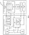
- FIG. 1is a block diagram of an example environment in which implementations disclosed herein may be implemented.
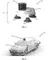
- FIG. 2is an image illustrating an example of a removable pod according to implementations disclosed herein.
- FIG. 3is an image illustrating an example of a removable pod mounted on a vehicle according to implementations disclosed herein.
- FIG. 4is a flowchart illustrating an example process in accordance with implementations disclosed herein.
- FIG. 5is an image illustrating example measurements of a removable pod mounted on a vehicle in accordance with implementations disclosed herein.
- FIG. 6is an image illustrating another example measurements of a removable pod mounted on a vehicle in accordance with implementations disclosed herein.
- FIG. 7is flowchart illustrating another example process in accordance with implementations disclosed herein.
- FIG. 8illustrates an example architecture of a computing device.
- Example environment 100 in FIG. 1includes external removable pod hardware 102 and vehicle cabin removable pod hardware 116 .
- External removable pod hardware 102can include a variety of sensors to collect environmental data.
- a pod sensor suitecan include LIDAR unit 104 , wide field of view camera 106 , narrow field of view camera 108 , 3D positioning sensors 112 such one or more Global Navigation Satellite Systems including: GPS, Global Navigation Satellite System (“GLONASS”), BeiDou Navigation Satellite System (“BDS”), Galileo, etc., IMU 114 , etc.
- PCB 110can be utilized to provide connections between various sensors within the sensor suite of external removable pod hardware 102 .
- one or more components of external removable pod hardware 102can be contained in hardware housing 206 as illustrated in FIG. 2 .
- Vehicle cabin removable pod hardware 116can be separate from the mountable pod hardware.
- vehicle cabin removable pod hardware 116can include USB adapters 118 , 120 , computing device 122 , AC adapter 124 , 12V vehicle receptacle 126 , OBDII port 128 , etc.
- Computing device 122can include a variety of devices including a laptop computing device, a tablet computing device, a cellular telephone computing device, etc.
- the vehicle itselfcan power external removable pod hardware 102 and/or computing device 122 .
- 12V vehicle receptacle 126can connect to PCB 110 to provide power to external removable pod hardware 102 .
- 12V vehicle receptacle 126can provide power to AC adapter 124 .
- AC adapter 124can provide power to computing device 122 .
- computing device 122can include one or more USB ports, each of which can connect to one or more USB adapters such as USB adapter 118 , 120 .
- Environmental data collected by one or more cameras 106 / 108 for example,can be transmitted via a USB adapter to computing device 122 . Additionally or alternatively, one or more cameras can receive power using a USB adapter. Furthermore, computing device 122 can transmit one or more control signals to one or more cameras utilizing connections made by USB adapters. For example, wide field of view camera 106 can transmit environmental data to computing device 122 , receive command signals from computing device 122 , and/or be powered utilizing USB adapter 118 . Similarly, narrow field of view camera 108 can transmit environmental data to computing device 122 , receive command signals from computing device 122 , and/or be powered utilizing USB adapter 120 . In some implementations, multiple cameras can connect to computing device 112 via a single USB adapter.
- any of a variety of camerascan be used including the aforementioned wide field of view camera 106 and narrow field of view camera 108 as well as a light field camera, a thermal imaging camera, etc.
- one or more camerascan connect directly to PCB 110 (not illustrated).
- Computing device 122can connect to PCB 110 in external removable pod hardware 102 via an Ethernet connection.
- an Ethernet connectioncan be a wired connection. Additionally or alternatively, an Ethernet connection can be a wireless connection.
- Computing device 122can transmit information to PCB 110 as well as receive environmental data collected by a variety of sensors in the external removable hardware pod 102 via the Ethernet connection.
- 3D positioning sensors 112can be integrated directly into PCB 110 . In other implementations, 3D positioning sensors 112 can be separate and connect with PCB 110 (not illustrated).
- PCB 110can provide power (for example 12V) to a variety of sensors including 3D positioning sensors 112 , LIDAR unit 104 , IMU 114 , wide field of view camera 106 (not illustrated), narrow field of view camera 108 (not illustrated), etc.
- PCB 110can synchronize timing with LIDAR unit 104 via a serial pulse per second (“PPS”) connection, an Ethernet connection, and/or additional connections.
- PPSserial pulse per second
- PCB 110 and LIDAR unit 104can transmit and receive data via an Ethernet connection.
- environmental data collected by LIDAR unit 104can be transmitted to PCB 110 via an Ethernet connection.
- PCB 110can transmit and receive information with IMU 114 .
- PCB 110can interface with vehicle data ports, such as OBDII port 128 , to additionally collect a variety of corresponding vehicle data.
- computing device 122can interface with a vehicle data port including OBDII port 128 to collect a variety of additional vehicle data (not pictured) such as information collected from the additional vehicle's CAN bus.
- Additional vehicle datain accordance with many implementations can include: vehicle speed data, braking data, steering control data, etc.
- environmental data and/or vehicle datacan be appended with a time stamp by PCB 110 , computing device 122 , and/or individual sensors (e.g., LIDAR units can generate their own time stamps). Additionally or alternatively, time stamped environmental and/or time stamped vehicle data can be combined and uploaded to the cloud using computing device 122 in conjunction with known communication pathways and hardware.
- the removable podcan combine time stamped environmental and time stamped vehicle data by creating an instance of data at each time step (i.e., each instance of data can include environmental data at a specific time stamp (if any) as well as vehicle data at the same specific time stamp (if any)).
- FIG. 2illustrates an image 200 of a removable pod in accordance with implementations disclosed herein.
- Removable pod 202can include a variety of elements such as one or more sensors 204 , hardware housing 206 , removable pod mount(s) 208 , etc.
- One or more sensors 204 which can be utilized in removable pod 202are illustrated in FIG. 1 .
- a LIDAR unitcan be the highest point on a removable pod 202 .
- Hardware housing 206can protect various portions of removable pod 202 from weather elements such as rain, snow, wind, hot temperatures, cold temperatures, etc.
- a variety of shapes of hardware housingcan be utilized in removable pod 202 in addition or alternatively to hardware housing 206 as illustrated in FIG. 2 .
- hardware housing 206can include two or more housing units to house separate portions of the removable pod 202 as well as a different shaped hardware housing 206 .
- removable pod mount(s) 208can attach removable pod 202 to a vehicle.
- Removable pod mount(s) 208can be adjusted such that sensors within a removable pod 202 can collect data from a preferred defined position and/or location.
- removable pod mount(s) 208can be adjusted to compensate for different curvatures between different vehicles.
- Removable pod mount(s) 208can attach removable pod 202 to a vehicle in a variety of ways including: suction cups, magnets, adhesives (e.g., glue, tape), etc.
- removable pod mount(s) 208can be a single mount. Varying number of mounts can be included in removable pod 202 in accordance with various implementations.
- removable pod 202can include two removable pod mounts 208 , three removable pod mounts 208 , four removable pod mounts 208 , etc.
- three removable pod mounts 208can be arranged in a tripod style configuration.
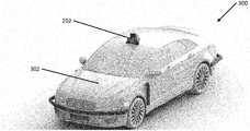
- FIG. 3illustrates an image of a removable pod mounted on a vehicle in accordance with implementations disclosed herein.
- Combined automobile and pod 300includes removable pod 202 mounted atop a vehicle 302 in a predefined preferred position.
- removable pod 202is vehicle agnostic and can be mounted on a variety of vehicles 302 including: cars, trucks, motorcycles, sports utility vehicles, vans, mopeds, tractor trailers, busses, motorized scooters, etc.
- components linked with removable pod 202can be inside vehicle 302 .
- vehicle cabin removable pod hardware 116(as illustrated in FIG. 1 ) can be inside the vehicle.
- vehicle cabin removable pod hardware 116can be inside a car, sports utility vehicle, truck, bus, etc.
- a laptop computercan be utilized as computing device 122 in removable pod hardware 116 , and the laptop computer can be stored inside the vehicle.
- a vehiclecan lack an enclosed interior and vehicle cabin removable pod hardware can be stored “in” the vehicle in additional ways.
- a motorcyclecan utilize a cellular telephone computing device as computing device 122 in removable pod hardware 116 .
- the motorcycle ridercan carry the cellular telephone in a pocket.
- the vehicle cabin removable pod hardware 116can be combined with the external removable pod hardware.
- various portions of the external removable pod hardware 102can be combine with selected portions of the vehicle cabin removable pod hardware 116 .
- a carcan have a removable pod 202 mounted to its front right side and an additional removable pod 202 can be mounted to its front left side.
- a vehicle pulling a trailercan have a removable pod 202 mounted to the vehicle and a second removable pod 202 mounted to the trailer to capture, for example, additional data when the trailer moves in a different direction from the vehicle.
- a buscan have three removable pods 202 mounted along the top to capture additional environmental data a single removable pod 202 could potentially miss because of the larger size of a bus when compared to a smaller vehicle such as a car.
- the removable podis not connected to the vehicle control system of the vehicle to which the pod is mounted upon. In other words, the removable pod collects data and does not generate and/or send signals to control the vehicle.
- FIG. 4an example process 400 for practicing selected aspects of the present disclosure, in accordance with various implementations is disclosed.
- This systemmay include various components of various computer devices, including those described in FIG. 1 and/or FIG. 8 .
- operations of process 400are shown in a particular order, this is not meant to be limiting.
- One or more operations, elements, and/or stepsmay be reordered, omitted, and/or added.
- environmental dataincludes a variety of information collected about a vehicle's surrounding environment.
- Environmental datacan be collected by one or more sensors in the removable pod including an IMU, a 3D positioning sensor (such as GPS), one or more cameras, a LIDAR unit, etc.
- environmental datacan be collected by one or more additional sensors included within the vehicle.
- environmental datacan include information collected by a rear backup camera in a vehicle.
- vehicle datacan be collected by one or more processors within the removable pod via a CAN bus which can, for example, be connected to an OBDII port in a vehicle.
- vehicle datacan include information relating to the control of a vehicle including vehicle speed data, vehicle braking data, vehicle steering control data, etc.
- the systemrecords collected environmental data and/or collected vehicle data can be recorded using the computing device.
- the computing devicesuch as computing device 112 (as illustrated in FIG. 2 ) can be stored inside a vehicle.
- a laptop computercan be utilized as the computing device and in some implementations can be stored inside a car.
- recordation of the datamay occur on a separate storage device operatively connected to the hardware 116 , incorporated with hardware 116 , or transmitted for recording remotely.
- the systemdetermines time stamps for instances of collected environmental and/or vehicle data. In many implementations, a time stamp can be associated with data using the computing device.
- sensorse.g., LIDAR units
- computing device time stampsif necessary.
- a PCB within removable pod hardwaresuch as PCB 110 as illustrated in FIG. 1
- the PCBcan provide time stamps for data collected by one or more sensors in the removable pod, and transmit environmental data with an associated time stamp to the computing device.
- the systemtransmits time stamped environmental data and/or time stamped vehicle data to a remote server for additional processing.
- additional processingcan combine time stamped environmental and/or time stamped vehicle data from several removable pods. Additionally or alternatively, time stamped environmental data and/or time stamped vehicle data can be utilized to generate training data for a machine learning model such as a machine learning model utilized to generate control signals for an autonomous vehicle.
- additional processingcan occur on the computing device (such as computing device 122 as illustrated in FIG. 1 ) prior to transmitting data to a remote server. Additional processing can occur in real time, near real time, and/or data can be stored and processed at later time.
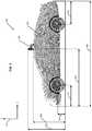
- FIG. 5illustrates an example combined vehicle and pod 500 of measurements of a removable pod mounted on a vehicle in accordance with implementations disclosed herein.
- FIG. 6illustrates another example combined vehicle and pod 600 of measurements of a removable pod mounted on a vehicle.
- Images 500 and 600include removable pod 202 and vehicle 302 similar to a removable pod and vehicle described in one or more of FIGS. 1-3 .
- Image 500includes a view of a removable pod mounted to a vehicle with respect to an X axis and a Z axis 516 where the X axis is in a direction substantially perpendicular to the Z axis.
- Image 600illustrates a view of a removable pod mounted to a vehicle with respect to an X axis and a Y axis 608 where the X axis is substantially perpendicular to the Y axis.
- positions of a removable pod mounted on a vehicle as well as dimensions of a vehiclecan be determined by measurements in an X axis, a Y axis, and a Z axis.
- vehicle measurementscan be utilized to determine the position of a removable pod mounted on a vehicle, and for example, if a pod is mounted in a correct position.
- a removable podcan be mounted in many positions. For example, a removable pod can be placed in many locations on the top of a car including the front center, the front left, the front right, the center of the middle of the car, etc.
- a variety of measurementscan be taken of the position of removable pod 202 mounted on vehicle 302 as well as measurements of the dimensions of vehicle 302 .
- one or more sensors in a mounted removable podcan determine various measurements.
- vehicle measurementscan be determined from a database of known vehicle information by a user providing the removable pod with identifying vehicle information (i.e., vehicle make, vehicle model, vehicle year, etc.).
- a humancan manually take measurements of a vehicle and/or removable pod mounted on a vehicle.
- vehicle and/or removable pod measurementscan be determined by a combination of measurements from one or more sensors in a removable pod, known vehicle measurements of various vehicles from a database, and/or manual measurements by a user.
- the position of a mounted removable podcan be determined in three dimensions by measuring pod height 502 (Z axis), pod position X 504 (X axis) and pod position Y 604 (Y axis) as illustrated in FIGS. 5 and 6 .
- vehicle measurementscan be determined in three dimensions by measuring vehicle height 506 (Z axis), vehicle length 508 (X axis), and vehicle width 602 (Y axis).
- the front wheel positioncan be determined by measuring axel height 510 (Z axis) and front axle overhang 512 (X axis).
- rear wheel positioncan be determined by measuring axel height 510 (Z axis) and rear axle overhang 514 (Y axis).
- different types of vehiclescan be measured by a variety of sets of measurements.
- the set of measurements for a truckcan be different from the set of measurements for a motorized scooter.
- a variety of measurementscan be taken when multiple removable pods are mounted on the same vehicle.
- an example process 700can position a removable pod on a vehicle in accordance with various implementations is disclosed.
- This systemmay include various components of various computer systems, including those described in FIG. 1 and/or FIG. 8 .
- operations of process 700are shown in a particular order, this is not meant to be limiting.
- One or more operations, elements, and/or stepsmay be reordered, omitted, and/or added.
- the systemattaches a removable pod to a vehicle using one or more pod mount(s) similar to pod mount 208 illustrated in FIG. 2 .
- the position of the removable podis within the leveling capabilities of the pod mount(s).
- a removable podcan be mounted on a surface that is not flat (e.g., the curved hood of a car) such that adjustable pod mount(s) can position sensors within the removable pod in a valid location.
- removable pod mount(s)can attach a removable pod to a vehicle utilizing suction cups, magnets, adhesives, etc.
- a removable podcan be positioned as close to the front of a vehicle that is within the leveling capabilities of the pod mount(s).
- a removable podcan be placed in any position where pod mount(s) can position the sensor suite of the removable pod in a position to collect data.
- the systemadjusts the position of the removable pod using the pod mount(s).
- the height of leg(s) of pod mount(s)can be adjusted such that the sensor suite in the removable pod can collect data. Adjusting the height of a leg of a pod mount can increase or decrease the height of a pod mount. Additionally or alternatively, the height of individual legs of pod mounts can each be adjusted independently for a removable pods with multiple pod mounts.
- the systemdetermines vehicle measurements and/or pod location measurements using one or more sensors in the removable pod.
- 3D positioning sensorssuch as GPS, cameras, etc., can gather vehicle dimension measurements and/or removable pod location measurements.
- the systemdetermines the current position of the removable pod.
- the position of a removable podcan be determined using a variety of measurements.
- a removable podcan utilize 3D positioning sensors (such as GPS), cameras, etc. and known information about vehicle measurements (e.g., manually measured vehicle measurements, vehicle measurements from known information about the specific vehicle, vehicle measurements taken using one or more sensors of the removable pod, etc.) to determine the positioning of a removable pod mounted on a vehicle.
- the determined position of the removable podcan vary from the actual position of the removable pod. For example, a determined position of a mounted removable pod can vary by 10 cm in any direction and still provide accurate information. Additionally or alternatively, the determined position of a removable pod and the actual position of a removable pod can vary by additional increments such as twenty cm, fifteen cm, five cm, one cm, etc. in accordance with various implementations.
- the systemdetermines if the removable pod is positioned in a valid location.
- a removable podcan have multiple valid positions on a vehicle. If the system determines the removable pod is in a valid position, process 700 ends. Additionally or alternatively, if the removable pod is not in a valid position, the removable pod can be reattached in accordance with block 702 to the vehicle using one or more pod mount(s) and blocks 704 , 706 , 708 , 710 can repeat until the removable pod is mounted in a valid position.
- FIG. 8is a block diagram of an example computing device 810 that may optionally be utilized to perform one or more aspects of techniques described herein.
- one or more of external removable pod hardware 102 , vehicle cabin removable pod hardware 116 and/or other component(s)may comprise one or more components of the example computing device 810 .
- Computing device 810typically includes at least one processor 814 which communicates with a number of peripheral devices via bus subsystem 812 .
- peripheral devicesmay include a storage subsystem 824 , including, for example, a memory subsystem 825 and a file storage subsystem 826 , user interface output devices 820 , user interface input devices 822 , and a network interface subsystem 816 .
- the input and output devicesallow user interaction with computing device 810 .
- Network interface subsystem 816provides an interface to outside networks and is coupled to corresponding interface devices in other computing devices.
- User interface input devices 822may include a keyboard, pointing devices such as a mouse, trackball, touchpad, or graphics tablet, a scanner, a touchscreen incorporated into the display, audio input devices such as voice recognition systems, microphones, and/or other types of input devices.
- pointing devicessuch as a mouse, trackball, touchpad, or graphics tablet
- audio input devicessuch as voice recognition systems, microphones, and/or other types of input devices.
- use of the term “input device”is intended to include all possible types of devices and ways to input information into computing device 810 or onto a communication network.
- User interface output devices 820may include a display subsystem, a printer, a fax machine, or non-visual displays such as audio output devices.
- the display subsystemmay include a cathode ray tube (“CRT”), a flat-panel device such as a liquid crystal display (“LCD”), a projection device, or some other mechanism for creating a visible image.
- the display subsystemmay also provide non-visual display such as via audio output devices.
- output deviceis intended to include all possible types of devices and ways to output information from computing device 810 to the user or to another machine or computing device.
- Storage subsystem 824stores programming and data constructs that provide the functionality of some or all of the modules described herein.
- the storage subsystem 824may include the logic to perform selected aspects of one or more of the processes of FIG. 4 and FIG. 7 , as well as to implement various components depicted in FIG. 1 .
- Memory 825 used in the storage subsystem 824can include a number of memories including a main random access memory (“RAM”) 830 for storage of instructions and data during program execution and a read only memory (“ROM”) 832 in which fixed instructions are stored.
- a file storage subsystem 826can provide persistent storage for program and data files, and may include a hard disk drive, a floppy disk drive along with associated removable media, a CD-ROM drive, an optical drive, or removable media cartridges.
- the modules implementing the functionality of certain implementationsmay be stored by file storage subsystem 826 in the storage subsystem 824 , or in other machines accessible by the processor(s) 814 .
- Bus subsystem 812provides a mechanism for letting the various components and subsystems of computing device 810 communicate with each other as intended. Although bus subsystem 812 is shown schematically as a single bus, alternative implementations of the bus subsystem may use multiple busses.
- Computing device 810can be of varying types including a workstation, server, computing cluster, blade server, server farm, or any other data processing system or computing device. Due to the ever-changing nature of computers and networks, the description of computing device 810 depicted in FIG. 8 is intended only as a specific example for purposes of illustrating some implementations. Many other configurations of computing device 810 are possible having more or fewer components than the computing device depicted in FIG. 8 .
Landscapes
- Engineering & Computer Science (AREA)
- Physics & Mathematics (AREA)
- Radar, Positioning & Navigation (AREA)
- Remote Sensing (AREA)
- General Physics & Mathematics (AREA)
- Aviation & Aerospace Engineering (AREA)
- Automation & Control Theory (AREA)
- Computer Networks & Wireless Communication (AREA)
- Theoretical Computer Science (AREA)
- Electromagnetism (AREA)
- General Engineering & Computer Science (AREA)
- Mechanical Engineering (AREA)
- Traffic Control Systems (AREA)
- Optical Radar Systems And Details Thereof (AREA)
- Navigation (AREA)
Abstract
Description
Claims (20)
Priority Applications (10)
| Application Number | Priority Date | Filing Date | Title |
|---|---|---|---|
| US16/271,355US11163312B2 (en) | 2018-11-02 | 2019-02-08 | Removable automotive LIDAR data collection POD |
| KR1020217012268AKR102485684B1 (en) | 2018-11-02 | 2019-03-29 | Detachable Vehicle LIDAR Data Acquisition Pod |
| EP19722303.5AEP3874294A1 (en) | 2018-11-02 | 2019-03-29 | Removable automotive lidar data collection pod |
| JP2021523509AJP7125554B2 (en) | 2018-11-02 | 2019-03-29 | Separate vehicle LIDAR data collection pod |
| PCT/US2019/024947WO2020091832A1 (en) | 2018-11-02 | 2019-03-29 | Removable automotive lidar data collection pod |
| CA3118402ACA3118402C (en) | 2018-11-02 | 2019-03-29 | Removable automotive lidar data collection pod |
| CN201980071453.4ACN113287039A (en) | 2018-11-02 | 2019-03-29 | Detachable automobile LIDAR data collection pod |
| US17/516,240US11681298B2 (en) | 2018-11-02 | 2021-11-01 | Removable automotive LIDAR data collection pod |
| US18/195,341US12007781B2 (en) | 2018-11-02 | 2023-05-09 | Removable automotive LIDAR data collection pod |
| US18/670,554US12353216B2 (en) | 2018-11-02 | 2024-05-21 | Removable automotive LIDAR data collection pod |
Applications Claiming Priority (2)
| Application Number | Priority Date | Filing Date | Title |
|---|---|---|---|
| US201862755167P | 2018-11-02 | 2018-11-02 | |
| US16/271,355US11163312B2 (en) | 2018-11-02 | 2019-02-08 | Removable automotive LIDAR data collection POD |
Related Child Applications (1)
| Application Number | Title | Priority Date | Filing Date |
|---|---|---|---|
| US17/516,240ContinuationUS11681298B2 (en) | 2018-11-02 | 2021-11-01 | Removable automotive LIDAR data collection pod |
Publications (2)
| Publication Number | Publication Date |
|---|---|
| US20200142426A1 US20200142426A1 (en) | 2020-05-07 |
| US11163312B2true US11163312B2 (en) | 2021-11-02 |
Family
ID=70459740
Family Applications (4)
| Application Number | Title | Priority Date | Filing Date |
|---|---|---|---|
| US16/271,355Active2039-12-30US11163312B2 (en) | 2018-11-02 | 2019-02-08 | Removable automotive LIDAR data collection POD |
| US17/516,240ActiveUS11681298B2 (en) | 2018-11-02 | 2021-11-01 | Removable automotive LIDAR data collection pod |
| US18/195,341ActiveUS12007781B2 (en) | 2018-11-02 | 2023-05-09 | Removable automotive LIDAR data collection pod |
| US18/670,554ActiveUS12353216B2 (en) | 2018-11-02 | 2024-05-21 | Removable automotive LIDAR data collection pod |
Family Applications After (3)
| Application Number | Title | Priority Date | Filing Date |
|---|---|---|---|
| US17/516,240ActiveUS11681298B2 (en) | 2018-11-02 | 2021-11-01 | Removable automotive LIDAR data collection pod |
| US18/195,341ActiveUS12007781B2 (en) | 2018-11-02 | 2023-05-09 | Removable automotive LIDAR data collection pod |
| US18/670,554ActiveUS12353216B2 (en) | 2018-11-02 | 2024-05-21 | Removable automotive LIDAR data collection pod |
Country Status (7)
| Country | Link |
|---|---|
| US (4) | US11163312B2 (en) |
| EP (1) | EP3874294A1 (en) |
| JP (1) | JP7125554B2 (en) |
| KR (1) | KR102485684B1 (en) |
| CN (1) | CN113287039A (en) |
| CA (1) | CA3118402C (en) |
| WO (1) | WO2020091832A1 (en) |
Cited By (25)
| Publication number | Priority date | Publication date | Assignee | Title |
|---|---|---|---|---|
| USD950405S1 (en)* | 2020-01-31 | 2022-05-03 | Zoox, Inc. | Sensor housing |
| US11474418B2 (en)* | 2020-03-11 | 2022-10-18 | Tilta Inc. | Camera mount system |
| US20220417404A1 (en)* | 2019-12-16 | 2022-12-29 | Plusai, Inc. | System and method for sensor system against glare and control thereof |
| US20230113053A1 (en)* | 2021-10-12 | 2023-04-13 | R.A. Phillips Industries, Inc. | Trailer tandem position sensor |
| US11650415B2 (en) | 2019-12-16 | 2023-05-16 | Plusai, Inc. | System and method for a sensor protection mechanism |
| US11662231B2 (en) | 2019-12-16 | 2023-05-30 | Plusai, Inc. | System and method for a sensor protection assembly |
| US11681298B2 (en) | 2018-11-02 | 2023-06-20 | Aurora Operations, Inc. | Removable automotive LIDAR data collection pod |
| US11724669B2 (en) | 2019-12-16 | 2023-08-15 | Plusai, Inc. | System and method for a sensor protection system |
| US11731584B2 (en) | 2019-12-16 | 2023-08-22 | Plusai, Inc. | System and method for anti-tampering mechanism |
| US11738694B2 (en) | 2019-12-16 | 2023-08-29 | Plusai, Inc. | System and method for anti-tampering sensor assembly |
| US11754689B2 (en) | 2019-12-16 | 2023-09-12 | Plusai, Inc. | System and method for detecting sensor adjustment need |
| US11772667B1 (en) | 2022-06-08 | 2023-10-03 | Plusai, Inc. | Operating a vehicle in response to detecting a faulty sensor using calibration parameters of the sensor |
| USD1053031S1 (en) | 2023-01-20 | 2024-12-03 | Aurora Operations, Inc. | Front sensor pod |
| USD1054884S1 (en)* | 2023-01-20 | 2024-12-24 | Aurora Operations, Inc. | Right sensor pod |
| USD1054883S1 (en) | 2023-01-20 | 2024-12-24 | Aurora Operations, Inc. | Sensor console |
| USD1055716S1 (en) | 2023-01-20 | 2024-12-31 | Aurora Operations, Inc. | Right sensor wing |
| USD1056735S1 (en)* | 2023-01-20 | 2025-01-07 | Aurora Operations, Inc. | Left sensor pod |
| USD1056734S1 (en) | 2023-01-20 | 2025-01-07 | Aurora Operations, Inc. | Left sensor wing |
| USD1061362S1 (en) | 2023-01-20 | 2025-02-11 | Aurora Operations, Inc. | Left sensor pod |
| USD1061281S1 (en) | 2023-01-20 | 2025-02-11 | Aurora Operations, Inc. | Right sensor wing |
| USD1061278S1 (en)* | 2023-01-20 | 2025-02-11 | Aurora Operations, Inc. | Right sensor pod |
| USD1061396S1 (en) | 2023-01-20 | 2025-02-11 | Aurora Operations, Inc. | Front sensor pod |
| USD1074543S1 (en) | 2023-01-20 | 2025-05-13 | Aurora Operations, Inc. | Left sensor wing |
| USD1094228S1 (en) | 2023-01-20 | 2025-09-23 | Aurora Operations, Inc. | Sensor console |
| USD1095334S1 (en) | 2018-06-29 | 2025-09-30 | Zoox, Inc. | Vehicle toy, replica, and/or model |
Families Citing this family (18)
| Publication number | Priority date | Publication date | Assignee | Title |
|---|---|---|---|---|
| WO2018132632A1 (en) | 2017-01-13 | 2018-07-19 | Diversey, Inc. | Three-dimensional scanning using fixed planar distance sensors |
| US11209456B2 (en)* | 2019-02-22 | 2021-12-28 | Woven Planet North America, Inc. | Integrated movement measurement unit |
| US11608082B1 (en)* | 2019-03-27 | 2023-03-21 | Ridecell, Inc. | Roof-top autonomous vehicle control system |
| US11100329B1 (en)* | 2019-08-14 | 2021-08-24 | Lytx, Inc. | Ranging system data utilization for marking of video data of interest |
| DE102019129600B4 (en)* | 2019-11-04 | 2023-11-02 | Evitado Technologies GmbH | Portable sensor system |
| JP7327187B2 (en)* | 2020-01-31 | 2023-08-16 | トヨタ自動車株式会社 | Vehicles and automated driving systems |
| US11953623B2 (en)* | 2020-04-30 | 2024-04-09 | Zoox, Inc. | Sensor pod assembly |
| US20210405185A1 (en)* | 2020-06-30 | 2021-12-30 | Tusimple, Inc. | System and method providing truck-mounted sensors to detect trailer following vehicles and trailer conditions |
| JPWO2022049943A1 (en)* | 2020-09-04 | 2022-03-10 | ||
| US12032056B2 (en)* | 2020-09-08 | 2024-07-09 | Lyft, Inc. | Universal sensor assembly for vehicles |
| USD961422S1 (en) | 2020-10-23 | 2022-08-23 | Tusimple, Inc. | Lidar housing |
| US12153164B2 (en) | 2020-11-06 | 2024-11-26 | Volkswagen Group of America Investments, LLC | System and method for operating a retractable sensor of an autonomous vehicle |
| CN112572326A (en)* | 2020-12-22 | 2021-03-30 | 清华大学 | Embedded automatic driving vehicle wisdom top cap system and vehicle that has it |
| CN112902977B (en)* | 2021-01-27 | 2023-06-16 | 中山大学 | Data acquisition carrying bracket, data acquisition device and positioning and mapping method thereof |
| JP2022122713A (en)* | 2021-02-10 | 2022-08-23 | トヨタ自動車株式会社 | Self-driving module mounting structure |
| DE102021117311B4 (en)* | 2021-07-05 | 2024-08-22 | Spleenlab GmbH | Control and navigation device for an autonomously moving system and autonomously moving system |
| US20230415751A1 (en)* | 2022-06-22 | 2023-12-28 | Gm Cruise Holdings Llc | System and method to help supplement a vehicle?s sensor data |
| US20240326715A1 (en)* | 2023-03-31 | 2024-10-03 | Kodiak Robotics, Inc. | Method for installing and uninstalling a roof mounted sensor pod |
Citations (18)
| Publication number | Priority date | Publication date | Assignee | Title |
|---|---|---|---|---|
| US6322275B1 (en)* | 1997-09-08 | 2001-11-27 | Robert Bosch Gmbh | Device for mounting a distance sensor on a motor vehicle |
| US20070219720A1 (en) | 2006-03-16 | 2007-09-20 | The Gray Insurance Company | Navigation and control system for autonomous vehicles |
| US20100052945A1 (en) | 1997-10-22 | 2010-03-04 | Intelligent Technologies International, Inc. | Vehicular Communication Arrangement and Method |
| US20120153087A1 (en) | 2008-08-06 | 2012-06-21 | Honeywell International Inc. | Modular Pods for Use with an Unmanned Aerial Vehicle |
| WO2014168851A1 (en) | 2013-04-11 | 2014-10-16 | Google Inc. | Methods and systems for detecting weather conditions using vehicle onboard sensors |
| US20140350768A1 (en) | 2005-10-21 | 2014-11-27 | Deere & Company | Versatile robotic control module |
| US20170016870A1 (en)* | 2012-06-01 | 2017-01-19 | Agerpoint, Inc. | Systems and methods for determining crop yields with high resolution geo-referenced sensors |
| US20170076227A1 (en) | 2014-03-03 | 2017-03-16 | Inrix Inc., | Traffic obstruction detection |
| US9606539B1 (en) | 2015-11-04 | 2017-03-28 | Zoox, Inc. | Autonomous vehicle fleet service and system |
| US9734455B2 (en) | 2015-11-04 | 2017-08-15 | Zoox, Inc. | Automated extraction of semantic information to enhance incremental mapping modifications for robotic vehicles |
| US20170270361A1 (en) | 2016-03-15 | 2017-09-21 | Solfice Research, Inc. | Systems and methods for providing vehicle cognition |
| US20180031678A1 (en) | 2016-07-28 | 2018-02-01 | Strobe, Inc. | Distributed Vehicle Lidar System |
| US20180136644A1 (en) | 2015-11-04 | 2018-05-17 | Zoox, Inc. | Machine learning systems and techniques to optimize teleoperation and/or planner decisions |
| US10007269B1 (en) | 2017-06-23 | 2018-06-26 | Uber Technologies, Inc. | Collision-avoidance system for autonomous-capable vehicle |
| US20180188032A1 (en) | 2017-01-04 | 2018-07-05 | Qualcomm Incorporated | Systems and methods for using a global positioning system velocity in visual-inertial odometry |
| US20180188037A1 (en) | 2016-12-30 | 2018-07-05 | DeepMap Inc. | Occupancy Map Updates Based on Sensor Data Collected by Autonomous Vehicles |
| US20180307944A1 (en) | 2017-04-24 | 2018-10-25 | Baidu Usa Llc | Automatically collecting training data for object recognition with 3d lidar and localization |
| WO2020091832A1 (en) | 2018-11-02 | 2020-05-07 | Aurora Innovation, Inc. | Removable automotive lidar data collection pod |
Family Cites Families (40)
| Publication number | Priority date | Publication date | Assignee | Title |
|---|---|---|---|---|
| JP3651259B2 (en) | 1998-05-01 | 2005-05-25 | 日産自動車株式会社 | Preceding vehicle tracking control device |
| KR101496909B1 (en) | 2009-01-22 | 2015-02-27 | 삼성전자 주식회사 | robot |
| US8866906B1 (en)* | 2010-03-31 | 2014-10-21 | Cris Abad | Land vehicle based surveillance system |
| DE102013100446B4 (en) | 2012-01-25 | 2020-01-09 | Denso Corporation | Tracking control system |
| US20130218518A1 (en)* | 2012-02-21 | 2013-08-22 | International Business Machines Corporation | Automated, three dimensional mappable environmental sampling system and methods of use |
| EP2637072B1 (en) | 2012-03-05 | 2017-10-11 | Volvo Car Corporation | Path following of a target vehicle |
| US10520482B2 (en)* | 2012-06-01 | 2019-12-31 | Agerpoint, Inc. | Systems and methods for monitoring agricultural products |
| US8849494B1 (en) | 2013-03-15 | 2014-09-30 | Google Inc. | Data selection by an autonomous vehicle for trajectory modification |
| US8983705B2 (en) | 2013-04-30 | 2015-03-17 | Google Inc. | Methods and systems for detecting weather conditions including fog using vehicle onboard sensors |
| US20140347440A1 (en)* | 2013-05-23 | 2014-11-27 | Sylvester Hatcher | Omnidirectional Vehicle Camera System |
| KR101470221B1 (en) | 2013-10-17 | 2014-12-05 | 현대자동차주식회사 | Apparatus for controlling suspension and method thereof |
| KR20160000573A (en) | 2014-06-24 | 2016-01-05 | 주식회사 다이렉트 | Method Of Direct Transaction For Hyper Maket and Management System Using The Same |
| KR20160000573U (en)* | 2014-08-08 | 2016-02-17 | 이정용 | Automobile IP camera fixing equipment |
| EP3281033B1 (en) | 2015-04-07 | 2022-01-12 | GM Global Technology Operations LLC | Compact lidar system |
| US9940834B1 (en) | 2016-01-22 | 2018-04-10 | State Farm Mutual Automobile Insurance Company | Autonomous vehicle application |
| CN205395966U (en)* | 2016-03-10 | 2016-07-27 | 零度智控(北京)智能科技有限公司 | On -vehicle cradle head device and on -vehicle camera system |
| EP3432285A4 (en) | 2016-03-16 | 2019-03-27 | Panasonic Intellectual Property Management Co., Ltd. | Driving analysis apparatus and driving analysis system |
| CN205554075U (en)* | 2016-04-28 | 2016-09-07 | 深圳市中智仿真科技有限公司 | Device is shot to on -vehicle meter step |
| US20180188736A1 (en) | 2016-08-16 | 2018-07-05 | Faraday&Future Inc. | System and method for vehicle localization assistance using sensor data |
| US20180053102A1 (en) | 2016-08-16 | 2018-02-22 | Toyota Jidosha Kabushiki Kaisha | Individualized Adaptation of Driver Action Prediction Models |
| EP3285230B1 (en) | 2016-08-19 | 2021-04-07 | Veoneer Sweden AB | Enhanced object detection and motion estimation for a vehicle environment detection system |
| US10592805B2 (en) | 2016-08-26 | 2020-03-17 | Ford Global Technologies, Llc | Physics modeling for radar and ultrasonic sensors |
| US20180113210A1 (en) | 2016-10-21 | 2018-04-26 | Waymo Llc | Mountable Radar System |
| US20180150083A1 (en) | 2016-11-29 | 2018-05-31 | Waymo Llc | Pod connection for Autonomous Vehicle Sensors |
| US10145945B2 (en) | 2017-01-11 | 2018-12-04 | Toyota Research Institute, Inc. | Systems and methods for automatically calibrating a LIDAR using information from a secondary vehicle |
| US10037613B1 (en) | 2017-03-30 | 2018-07-31 | Uber Technologies, Inc. | Systems and methods to track vehicles proximate perceived by an autonomous vehicle |
| US11209825B2 (en) | 2017-07-01 | 2021-12-28 | International Business Machines Corporation | Moving traffic obstacle detection and avoidance |
| CN111587407B (en) | 2017-11-10 | 2024-01-23 | 辉达公司 | System and method for a safe and reliable autonomous vehicle |
| US11017550B2 (en) | 2017-11-15 | 2021-05-25 | Uatc, Llc | End-to-end tracking of objects |
| US11232350B2 (en) | 2017-11-29 | 2022-01-25 | Honda Motor Co., Ltd. | System and method for providing road user classification training using a vehicle communications network |
| US20190179317A1 (en) | 2017-12-13 | 2019-06-13 | Luminar Technologies, Inc. | Controlling vehicle sensors using an attention model |
| US10906536B2 (en) | 2018-04-11 | 2021-02-02 | Aurora Innovation, Inc. | Control of autonomous vehicle based on determined yaw parameter(s) of additional vehicle |
| US11164016B2 (en) | 2018-05-17 | 2021-11-02 | Uatc, Llc | Object detection and property determination for autonomous vehicles |
| US10755575B2 (en) | 2018-08-30 | 2020-08-25 | Cisco Technology, Inc. | Raw sensor data sharing for enhanced fleet-wide environmental awareness and safety |
| US11182986B2 (en) | 2018-10-10 | 2021-11-23 | Micron Technology, Inc. | Real-time selection of data to collect in autonomous vehicle |
| US11209821B2 (en) | 2018-11-02 | 2021-12-28 | Aurora Operations, Inc. | Labeling autonomous vehicle data |
| US11829143B2 (en) | 2018-11-02 | 2023-11-28 | Aurora Operations, Inc. | Labeling autonomous vehicle data |
| US11256263B2 (en) | 2018-11-02 | 2022-02-22 | Aurora Operations, Inc. | Generating targeted training instances for autonomous vehicles |
| US11403492B2 (en) | 2018-11-02 | 2022-08-02 | Aurora Operations, Inc. | Generating labeled training instances for autonomous vehicles |
| US11086319B2 (en) | 2018-11-02 | 2021-08-10 | Aurora Operations, Inc. | Generating testing instances for autonomous vehicles |
- 2019
- 2019-02-08USUS16/271,355patent/US11163312B2/enactiveActive
- 2019-03-29CACA3118402Apatent/CA3118402C/enactiveActive
- 2019-03-29WOPCT/US2019/024947patent/WO2020091832A1/ennot_activeCeased
- 2019-03-29EPEP19722303.5Apatent/EP3874294A1/enactivePending
- 2019-03-29KRKR1020217012268Apatent/KR102485684B1/enactiveActive
- 2019-03-29CNCN201980071453.4Apatent/CN113287039A/enactivePending
- 2019-03-29JPJP2021523509Apatent/JP7125554B2/enactiveActive
- 2021
- 2021-11-01USUS17/516,240patent/US11681298B2/enactiveActive
- 2023
- 2023-05-09USUS18/195,341patent/US12007781B2/enactiveActive
- 2024
- 2024-05-21USUS18/670,554patent/US12353216B2/enactiveActive
Patent Citations (20)
| Publication number | Priority date | Publication date | Assignee | Title |
|---|---|---|---|---|
| US6322275B1 (en)* | 1997-09-08 | 2001-11-27 | Robert Bosch Gmbh | Device for mounting a distance sensor on a motor vehicle |
| US20100052945A1 (en) | 1997-10-22 | 2010-03-04 | Intelligent Technologies International, Inc. | Vehicular Communication Arrangement and Method |
| US20140350768A1 (en) | 2005-10-21 | 2014-11-27 | Deere & Company | Versatile robotic control module |
| US20070219720A1 (en) | 2006-03-16 | 2007-09-20 | The Gray Insurance Company | Navigation and control system for autonomous vehicles |
| US20120153087A1 (en) | 2008-08-06 | 2012-06-21 | Honeywell International Inc. | Modular Pods for Use with an Unmanned Aerial Vehicle |
| US20170016870A1 (en)* | 2012-06-01 | 2017-01-19 | Agerpoint, Inc. | Systems and methods for determining crop yields with high resolution geo-referenced sensors |
| WO2014168851A1 (en) | 2013-04-11 | 2014-10-16 | Google Inc. | Methods and systems for detecting weather conditions using vehicle onboard sensors |
| US20170076227A1 (en) | 2014-03-03 | 2017-03-16 | Inrix Inc., | Traffic obstruction detection |
| US20180136644A1 (en) | 2015-11-04 | 2018-05-17 | Zoox, Inc. | Machine learning systems and techniques to optimize teleoperation and/or planner decisions |
| US9606539B1 (en) | 2015-11-04 | 2017-03-28 | Zoox, Inc. | Autonomous vehicle fleet service and system |
| US9734455B2 (en) | 2015-11-04 | 2017-08-15 | Zoox, Inc. | Automated extraction of semantic information to enhance incremental mapping modifications for robotic vehicles |
| US20170270361A1 (en) | 2016-03-15 | 2017-09-21 | Solfice Research, Inc. | Systems and methods for providing vehicle cognition |
| US20180031678A1 (en) | 2016-07-28 | 2018-02-01 | Strobe, Inc. | Distributed Vehicle Lidar System |
| US20180188037A1 (en) | 2016-12-30 | 2018-07-05 | DeepMap Inc. | Occupancy Map Updates Based on Sensor Data Collected by Autonomous Vehicles |
| US20180188032A1 (en) | 2017-01-04 | 2018-07-05 | Qualcomm Incorporated | Systems and methods for using a global positioning system velocity in visual-inertial odometry |
| US20180307944A1 (en) | 2017-04-24 | 2018-10-25 | Baidu Usa Llc | Automatically collecting training data for object recognition with 3d lidar and localization |
| US10007269B1 (en) | 2017-06-23 | 2018-06-26 | Uber Technologies, Inc. | Collision-avoidance system for autonomous-capable vehicle |
| WO2020091832A1 (en) | 2018-11-02 | 2020-05-07 | Aurora Innovation, Inc. | Removable automotive lidar data collection pod |
| CN113287039A (en) | 2018-11-02 | 2021-08-20 | 欧若拉创新公司 | Detachable automobile LIDAR data collection pod |
| EP3874294A1 (en) | 2018-11-02 | 2021-09-08 | Aurora Operations, Inc. | Removable automotive lidar data collection pod |
Non-Patent Citations (29)
| Title |
|---|
| 360 FLY; The Cameras That Miss Nothing. And Change Everything, https://www.369fly.com/shop/cameras, Jun. 5, 2018. |
| Amazon.com; Delkin DDMNT-TRIPLE Fat Gecko Three-Arm Suction Mount (Black): Professional Video Tripods Camera & Photo, https://www.amazon.com/gp/product/B00A86MMY8, Jun. 5, 2018. |
| Amazon.com; RIDIC Accessories, Large Street View Ready Camera Mount: Camera & Photo; https://www.amazon.com/dp/B075CYB215, Jun. 5, 2018. |
| Bojarski, et al.; End to End Learning for Self-Driving Cars, Apr. 25, 2016. |
| Bojarski, et al.; End to End Learning for Self-Driving Cars, dated Apr. 25, 2016. |
| Canadian Patent App. No. 3,118,402 entered national stage on Apr. 30, 2021. |
| Chinese Patent App. No. 201980071453.4 entered national stage on Apr. 28, 2021. |
| Cortica Automotive; It's Not Enough to Recognize A Traffic Light 99% of the Time, http://www.cortica.com/automotive/index.html, dated Jun. 5, 2018. |
| Desjardins, C. et al.; Cooperative Adaptive Cruise Control: A Reinforcement Learning Approach; IEEEE, vol. 12, No. 4; pp. 1248-1260; dated Dec. 2011. |
| Dresner, et al.; A Multiagent Approach to Autonomous Intersection Management, Journal of Artificial Intelligence Research 31 (2008) 591-656, dated Mar. 2018. |
| Dresner, Kurt, et al.; Stone P. (2006) Multiagent Traffic Management: Opportunities for Multiagent Learning. In: Tuyls K., Hoen P.J., Verbeeck K., Sen S. (eds) Learning and Adaption in Multi-Agent Systems. LAMAS; Lecture Votes in Computer Science, vol. 3898. Springer, Berlin, Heidelberg, dated 2005. |
| European Patent App. No. 19722303.5 entered national stage on May 27, 2021. |
| European Patent Office, Communication pursuant to Rules 161(1) and 162EPC for app. No. 19722303.5 dated Jun. 11, 2021. |
| European Patent Office, International Preliminary Report on Patentability for PCT/US2019/024947 dated Apr. 27, 2021. |
| Google; Accessorize Your Camera—Google Street View, https://www.google.com/streetview/publish/mounts/, Jun. 5, 2018. |
| Google; Create Street View in a Snap—Google Street View, https://www.google.com/streetview/publish/, Jun. 5, 2018. |
| INSTA360; Insta360 Pro, https://mall.insta360.com/product/pro, Jun. 5, 2018. |
| International Searching Authority; Search Report and Written Opinion for PCT Application No. PCT/US2019/024947; 12 pages; dated Jun. 25, 2019. |
| Japanese Patent App. No. 2021-523509 entered national stage on Apr. 28, 2021. |
| Korean Patent App. No. 10-2021-7012268 entered national stage on Apr. 23, 2021. |
| Matterport; Matterport Pro2 3D Camera Specifications, https://support.matterport.com/hc/en-US/articles/115004093167, Jun. 5, 2018. |
| Michels, Jeff, et al.; High Speed Obstacle Avoidance using Monocular Vision and Reinforcement Learning, Somputer Science Department, Stanford University, Proceedings of the 22nd International Conference on Machine Learning, Bonn, Germany, dated 2005. |
| NC Tech; iSTAR Camera, Amazing Results with the iSTAR Panoramic Camera, https://www.nctechimaging.com/istar/, Jun. 5, 2018. |
| NC Tech; The iSTAR Pulsar big data capture system, https://www.nctechimaging.com/istar-pulsar-techspec/, Jun. 5, 2018. |
| Pongpunwattana, Anawat, et al.; Real-Time Planning for Multiple Autonomous Vehicles in Dynamic Jncertain Environments. Journal of Aerospace Computing Information and Communication—J AEROSP COMPUT INF 7,0MMUN. 1.580-604. 10.2514/1.12919. 2004. |
| Ricoh Company; THETA V, https://theta360.eom/en/about/theta/v.html, Jun. 5, 2018. |
| Roderick, Norman, et al.; Reinforcement Learning for Autonomous Vehicles; dated 2002. |
| Ye, H. et al.: Machine LEarning for Vehicular Networks: Recent Advances and Application Examples; IEEE, vol. 13, No. 2; pp. 94-101; dated Jun. 1, 2018. |
| YI Technology; Yl 360 VR Camera, https://www.yitechnology.com/yi-360-vr-camera-specs, Jun. 5, 2018. |
Cited By (31)
| Publication number | Priority date | Publication date | Assignee | Title |
|---|---|---|---|---|
| USD1095334S1 (en) | 2018-06-29 | 2025-09-30 | Zoox, Inc. | Vehicle toy, replica, and/or model |
| US11681298B2 (en) | 2018-11-02 | 2023-06-20 | Aurora Operations, Inc. | Removable automotive LIDAR data collection pod |
| US12353216B2 (en) | 2018-11-02 | 2025-07-08 | Aurora Operations, Inc. | Removable automotive LIDAR data collection pod |
| US12007781B2 (en) | 2018-11-02 | 2024-06-11 | Aurora Operations, Inc. | Removable automotive LIDAR data collection pod |
| US11724669B2 (en) | 2019-12-16 | 2023-08-15 | Plusai, Inc. | System and method for a sensor protection system |
| US20220417404A1 (en)* | 2019-12-16 | 2022-12-29 | Plusai, Inc. | System and method for sensor system against glare and control thereof |
| US11650415B2 (en) | 2019-12-16 | 2023-05-16 | Plusai, Inc. | System and method for a sensor protection mechanism |
| US11722787B2 (en)* | 2019-12-16 | 2023-08-08 | Plusai, Inc. | System and method for sensor system against glare and control thereof |
| US11662231B2 (en) | 2019-12-16 | 2023-05-30 | Plusai, Inc. | System and method for a sensor protection assembly |
| US11731584B2 (en) | 2019-12-16 | 2023-08-22 | Plusai, Inc. | System and method for anti-tampering mechanism |
| US11738694B2 (en) | 2019-12-16 | 2023-08-29 | Plusai, Inc. | System and method for anti-tampering sensor assembly |
| US11754689B2 (en) | 2019-12-16 | 2023-09-12 | Plusai, Inc. | System and method for detecting sensor adjustment need |
| USD1063662S1 (en) | 2020-01-31 | 2025-02-25 | Zoox, Inc. | Vehicle with sensor housings |
| USD950405S1 (en)* | 2020-01-31 | 2022-05-03 | Zoox, Inc. | Sensor housing |
| US11474418B2 (en)* | 2020-03-11 | 2022-10-18 | Tilta Inc. | Camera mount system |
| US20230113053A1 (en)* | 2021-10-12 | 2023-04-13 | R.A. Phillips Industries, Inc. | Trailer tandem position sensor |
| US12306294B2 (en)* | 2021-10-12 | 2025-05-20 | R.A. Phillips Industries, Inc. | Trailer tandem position sensor |
| US11772667B1 (en) | 2022-06-08 | 2023-10-03 | Plusai, Inc. | Operating a vehicle in response to detecting a faulty sensor using calibration parameters of the sensor |
| USD1053031S1 (en) | 2023-01-20 | 2024-12-03 | Aurora Operations, Inc. | Front sensor pod |
| USD1056734S1 (en) | 2023-01-20 | 2025-01-07 | Aurora Operations, Inc. | Left sensor wing |
| USD1061362S1 (en) | 2023-01-20 | 2025-02-11 | Aurora Operations, Inc. | Left sensor pod |
| USD1061281S1 (en) | 2023-01-20 | 2025-02-11 | Aurora Operations, Inc. | Right sensor wing |
| USD1061278S1 (en)* | 2023-01-20 | 2025-02-11 | Aurora Operations, Inc. | Right sensor pod |
| USD1061396S1 (en) | 2023-01-20 | 2025-02-11 | Aurora Operations, Inc. | Front sensor pod |
| USD1056735S1 (en)* | 2023-01-20 | 2025-01-07 | Aurora Operations, Inc. | Left sensor pod |
| USD1072645S1 (en) | 2023-01-20 | 2025-04-29 | Aurora Operations, Inc. | Sensor console |
| USD1074543S1 (en) | 2023-01-20 | 2025-05-13 | Aurora Operations, Inc. | Left sensor wing |
| USD1055716S1 (en) | 2023-01-20 | 2024-12-31 | Aurora Operations, Inc. | Right sensor wing |
| USD1054883S1 (en) | 2023-01-20 | 2024-12-24 | Aurora Operations, Inc. | Sensor console |
| USD1094228S1 (en) | 2023-01-20 | 2025-09-23 | Aurora Operations, Inc. | Sensor console |
| USD1054884S1 (en)* | 2023-01-20 | 2024-12-24 | Aurora Operations, Inc. | Right sensor pod |
Also Published As
| Publication number | Publication date |
|---|---|
| JP7125554B2 (en) | 2022-08-24 |
| US20200142426A1 (en) | 2020-05-07 |
| WO2020091832A1 (en) | 2020-05-07 |
| US11681298B2 (en) | 2023-06-20 |
| US12007781B2 (en) | 2024-06-11 |
| US20230350417A1 (en) | 2023-11-02 |
| EP3874294A1 (en) | 2021-09-08 |
| CN113287039A (en) | 2021-08-20 |
| US12353216B2 (en) | 2025-07-08 |
| CA3118402A1 (en) | 2020-05-07 |
| KR102485684B1 (en) | 2023-01-05 |
| US20240310837A1 (en) | 2024-09-19 |
| US20220050471A1 (en) | 2022-02-17 |
| CA3118402C (en) | 2023-07-04 |
| KR20210062684A (en) | 2021-05-31 |
| JP2022506281A (en) | 2022-01-17 |
Similar Documents
| Publication | Publication Date | Title |
|---|---|---|
| US12353216B2 (en) | Removable automotive LIDAR data collection pod | |
| US11829143B2 (en) | Labeling autonomous vehicle data | |
| US11403492B2 (en) | Generating labeled training instances for autonomous vehicles | |
| US11630458B2 (en) | Labeling autonomous vehicle data | |
| US11774966B2 (en) | Generating testing instances for autonomous vehicles | |
| US11256263B2 (en) | Generating targeted training instances for autonomous vehicles | |
| US10210672B2 (en) | Systems and methods for remotely controlling data collection by a vehicle | |
| US20200201351A1 (en) | Model for Excluding Vehicle from Sensor Field Of View | |
| JPWO2020091832A5 (en) | ||
| US12198382B2 (en) | Automatic trailer camera calibration | |
| Cheok et al. | Validation of scenario-based virtual safety testing using low-cost sensor-based instrumented vehicle | |
| CN115792988B (en) | A dead reckoning trajectory accuracy estimation method and system | |
| EP4436136A1 (en) | File format for selective streaming of data | |
| CN202422262U (en) | System with laser heavy rainfall and dense fog anti-collision caution, navigation and night vision travelling record functions | |
| CN203358438U (en) | Three-dimensional data collection vehicle for construction of three-dimensional digital power transmission and transformation grid | |
| US20240037996A1 (en) | Infrastructure to support real-time review of events | |
| KR20230054067A (en) | Gnss-based vehicle driving test device using slope correction | |
| CA3225174A1 (en) | Data manager | |
| KR20230054062A (en) | Gnss-based vehicle driving test device |
Legal Events
| Date | Code | Title | Description |
|---|---|---|---|
| FEPP | Fee payment procedure | Free format text:ENTITY STATUS SET TO UNDISCOUNTED (ORIGINAL EVENT CODE: BIG.); ENTITY STATUS OF PATENT OWNER: LARGE ENTITY | |
| AS | Assignment | Owner name:AURORA INNOVATION, INC., CALIFORNIA Free format text:ASSIGNMENT OF ASSIGNORS INTEREST;ASSIGNORS:GIST, NATHANIEL, IV;WILLIAMS, CHRISTOPHER;REEL/FRAME:048295/0273 Effective date:20190211 | |
| FEPP | Fee payment procedure | Free format text:ENTITY STATUS SET TO SMALL (ORIGINAL EVENT CODE: SMAL); ENTITY STATUS OF PATENT OWNER: LARGE ENTITY | |
| STPP | Information on status: patent application and granting procedure in general | Free format text:NON FINAL ACTION MAILED | |
| AS | Assignment | Owner name:AURORA INNOVATION OPCO, INC., CALIFORNIA Free format text:MERGER AND CHANGE OF NAME;ASSIGNORS:AVIAN U MERGER SUB CORP.;AURORA INNOVATION, INC.;REEL/FRAME:056712/0669 Effective date:20210119 Owner name:AURORA OPERATIONS, INC., CALIFORNIA Free format text:CHANGE OF NAME;ASSIGNOR:AURORA INNOVATION OPCO, INC.;REEL/FRAME:056712/0676 Effective date:20210408 | |
| STPP | Information on status: patent application and granting procedure in general | Free format text:NOTICE OF ALLOWANCE MAILED -- APPLICATION RECEIVED IN OFFICE OF PUBLICATIONS | |
| FEPP | Fee payment procedure | Free format text:ENTITY STATUS SET TO UNDISCOUNTED (ORIGINAL EVENT CODE: BIG.); ENTITY STATUS OF PATENT OWNER: LARGE ENTITY | |
| STPP | Information on status: patent application and granting procedure in general | Free format text:AWAITING TC RESP., ISSUE FEE NOT PAID | |
| STPP | Information on status: patent application and granting procedure in general | Free format text:PUBLICATIONS -- ISSUE FEE PAYMENT RECEIVED | |
| STPP | Information on status: patent application and granting procedure in general | Free format text:PUBLICATIONS -- ISSUE FEE PAYMENT VERIFIED | |
| STCF | Information on status: patent grant | Free format text:PATENTED CASE | |
| MAFP | Maintenance fee payment | Free format text:PAYMENT OF MAINTENANCE FEE, 4TH YEAR, LARGE ENTITY (ORIGINAL EVENT CODE: M1551); ENTITY STATUS OF PATENT OWNER: LARGE ENTITY Year of fee payment:4 |