US11163285B2 - Servo driver - Google Patents
Servo driverDownload PDFInfo
- Publication number
- US11163285B2 US11163285B2US16/609,812US201816609812AUS11163285B2US 11163285 B2US11163285 B2US 11163285B2US 201816609812 AUS201816609812 AUS 201816609812AUS 11163285 B2US11163285 B2US 11163285B2
- Authority
- US
- United States
- Prior art keywords
- pulse
- transceiver
- conversion module
- button
- display
- Prior art date
- Legal status (The legal status is an assumption and is not a legal conclusion. Google has not performed a legal analysis and makes no representation as to the accuracy of the status listed.)
- Active, expires
Links
Images


Classifications
- H—ELECTRICITY
- H03—ELECTRONIC CIRCUITRY
- H03K—PULSE TECHNIQUE
- H03K5/00—Manipulating of pulses not covered by one of the other main groups of this subclass
- H03K5/01—Shaping pulses
- H—ELECTRICITY
- H02—GENERATION; CONVERSION OR DISTRIBUTION OF ELECTRIC POWER
- H02P—CONTROL OR REGULATION OF ELECTRIC MOTORS, ELECTRIC GENERATORS OR DYNAMO-ELECTRIC CONVERTERS; CONTROLLING TRANSFORMERS, REACTORS OR CHOKE COILS
- H02P8/00—Arrangements for controlling dynamo-electric motors rotating step by step
- H02P8/34—Monitoring operation
- G—PHYSICS
- G05—CONTROLLING; REGULATING
- G05B—CONTROL OR REGULATING SYSTEMS IN GENERAL; FUNCTIONAL ELEMENTS OF SUCH SYSTEMS; MONITORING OR TESTING ARRANGEMENTS FOR SUCH SYSTEMS OR ELEMENTS
- G05B19/00—Programme-control systems
- G05B19/02—Programme-control systems electric
- G05B19/04—Programme control other than numerical control, i.e. in sequence controllers or logic controllers
- G05B19/045—Programme control other than numerical control, i.e. in sequence controllers or logic controllers using logic state machines, consisting only of a memory or a programmable logic device containing the logic for the controlled machine and in which the state of its outputs is dependent on the state of its inputs or part of its own output states, e.g. binary decision controllers, finite state controllers
- H—ELECTRICITY
- H02—GENERATION; CONVERSION OR DISTRIBUTION OF ELECTRIC POWER
- H02M—APPARATUS FOR CONVERSION BETWEEN AC AND AC, BETWEEN AC AND DC, OR BETWEEN DC AND DC, AND FOR USE WITH MAINS OR SIMILAR POWER SUPPLY SYSTEMS; CONVERSION OF DC OR AC INPUT POWER INTO SURGE OUTPUT POWER; CONTROL OR REGULATION THEREOF
- H02M1/00—Details of apparatus for conversion
- G—PHYSICS
- G05—CONTROLLING; REGULATING
- G05B—CONTROL OR REGULATING SYSTEMS IN GENERAL; FUNCTIONAL ELEMENTS OF SUCH SYSTEMS; MONITORING OR TESTING ARRANGEMENTS FOR SUCH SYSTEMS OR ELEMENTS
- G05B2219/00—Program-control systems
- G05B2219/20—Pc systems
- G05B2219/25—Pc structure of the system
- G05B2219/25392—Convert control signal to deliver pulse modified in time and width
- H—ELECTRICITY
- H02—GENERATION; CONVERSION OR DISTRIBUTION OF ELECTRIC POWER
- H02M—APPARATUS FOR CONVERSION BETWEEN AC AND AC, BETWEEN AC AND DC, OR BETWEEN DC AND DC, AND FOR USE WITH MAINS OR SIMILAR POWER SUPPLY SYSTEMS; CONVERSION OF DC OR AC INPUT POWER INTO SURGE OUTPUT POWER; CONTROL OR REGULATION THEREOF
- H02M1/00—Details of apparatus for conversion
- H02M1/0064—Magnetic structures combining different functions, e.g. storage, filtering or transformation
Definitions
- Embodiments of inventiongenerally relate to a servo driver, and in particular to a servo driver which is capable of realizing the switching of a pulse type to adapt to various upper computers or PLCs.
- the pulse receiving mode for a servo drivercan be divided into three types: clockwise and counter-clockwise pulse control (CW+CCW), pulse plus direction control (pulse+direction) and AB-phase input control (also referred to as phase difference control, which is common in handwheel control), and the waveform diagrams of these three pulse forms are different from one another, for example, as shown in FIG. 1 .
- CW+CCWclockwise and counter-clockwise pulse control
- pulse plus direction controlpulse plus direction control
- AB-phase input controlalso referred to as phase difference control, which is common in handwheel control
- the embodiments of the present inventionprovide a novel servo driver.
- the servo driver of at least one embodimentcan convert the type of a pulse signal, so as to improve upon or even solve many problems caused by mismatching of the pulse signal type.
- At least one embodiment of the present inventionprovides a servo driver, comprising: a driver, a pulse conversion module and a pulse interface, wherein the pulse conversion module is connected between the pulse interface and the driver, and the pulse conversion module converts the type of a pulse control signal received by the pulse interface, and then outputs same to the driver, with the type of the pulse control signal comprising at least one of a clockwise and counter-clockwise pulse control type, a pulse plus direction control type and an AB-phase input control type.
- the servo driver of at least one embodiment of the present inventioncan use a pulse conversion module to convert the type of a pulse from an upper computer or a PLC, so as to solve the limitations where the type selection of the driver or the upper computer/PLC cannot be performed or the function thereof cannot be used due to the mismatching of the pulse signal type.
- FIG. 1exemplarily shows the pulse forms of three types of pulse control signals.
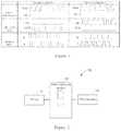
- FIG. 2shows a schematic structure of a servo driver according to the present invention.
- FIG. 3shows one embodiment of a pulse conversion module according to the present invention.
- FIG. 4shows one embodiment of a pulse conversion mode.
- At least one embodiment of the present inventionprovides a servo driver, comprising: a driver, a pulse conversion module and a pulse interface, wherein the pulse conversion module is connected between the pulse interface and the driver, and the pulse conversion module converts the type of a pulse control signal received by the pulse interface, and then outputs same to the driver, with the type of the pulse control signal comprising at least one of a clockwise and counter-clockwise pulse control type, a pulse plus direction control type and an AB-phase input control type.
- the servo driver of at least one embodiment of the present inventioncan use a pulse conversion module to convert the type of a pulse from an upper computer or a PLC, so as to solve the limitations where the type selection of the driver or the upper computer/PLC cannot be performed or the function thereof cannot be used due to the mismatching of the pulse signal type.
- the pulse conversion modulecomprises a complex programmable logic device, and pulse conversion logic for realizing the conversion between different pulse control system signal types is provided in the complex programmable logic device.
- the complex programmable logic devicecan be used for parallel processing, so as to eliminate the problem of time delays.
- the pulse conversion modulefurther comprises a display and a button which are in signal connection with the complex programmable logic device, wherein a user switches between various types of conversion modes via the button, and the display at least displays a conversion mode which is currently implemented by the pulse conversion module, so as to facilitate the user in operating and selecting a conversion mode for the pulse control signal.
- the displayis a 1-bit digital display, and different numbers displayed on the display represent different conversion modes.
- the pulse conversion modulecomprises two buttons, and the two buttons respectively realize the operations of adding one to and subtracting one from a number on the 1-bit digital display when being pressed down, so as to switch the conversion mode by means of either of the two buttons.
- the pulse conversion modulefurther comprises a first transceiver and a second transceiver which are in signal connection with the complex programmable logic device, wherein the first transceiver is in signal connection with the driver, and the second transceiver is in signal connection with the pulse interface.
- the pulse conversion modulecan be provided outside the driver, for example, on a cabinet, and the two are connected wirelessly.
- the pulse conversion moduleis provided on a housing of the servo driver or is provided outside a cabinet accommodating the servo driver, so as to expose the display and the buttons.
- the servo driver 10 of an embodiment of the present inventionmainly comprises: a driver 11 , a pulse conversion module 12 and a pulse interface 13 .
- the pulse conversion module 12is connected between the driver 11 and the pulse interface 13 , wherein the pulse conversion module 12 converts the type of a pulse control signal received by the pulse interface 13 , and then outputs same to the driver 11 .
- the type of the pulse control signalcomprises at least one of a clockwise and counter-clockwise pulse control type (CW+CCW), a pulse plus direction control type (pulse+direction) and an AB-phase input control type (also referred to as phase difference control).
- the servo driver 10 of an embodiment of the present inventionmay use the pulse conversion module 12 to convert the type of a pulse from an upper computer or a PLC, so as to solve the limitations where the type selection of the driver or the upper computer/PLC cannot be performed or the functions thereof cannot be used due to the mismatching of the pulse signal type.
- any form of conversion between pulse typescan also improve the anti-interference performance of the servo driver 10 , thereby avoiding a pulse loss or increase caused by pulse mismatching.
- the pulse conversion module 12may be a small-sized module with a small volume, so as to be conveniently configured on the servo driver 10 or provided on a cabinet accommodating the servo driver 10 .
- FIG. 3shows one embodiment of the pulse conversion module 12 according to the present invention.
- the pulse conversion module 12may further comprise a complex programmable logic device (CPLD) 14 , a display 15 , buttons 16 , a first transceiver 17 and a second transceiver 18 .
- the complex programmable logic device 14may perform parallel processing, so as to eliminate the problem of time delays.
- the use of the complex programmable logic device 14also has the advantages of a low cost and clear logic, etc.
- a pulse conversion logic for realizing the conversion between different pulse control system signal typesmay be provided in the complex programmable logic device 14 .
- the pulse conversion logicmay be hardware in the form of a semiconductor device, and may also be a data structure, a mapping table, a code, etc., in the form of a conversion table stored in a memory in the complex programmable logic device 14 .
- the pulse conversion logicmay convert a pulse control signal (being of a clockwise and counter-clockwise pulse control type in this example) from the pulse interface 13 according to a conversion method (for example, converting same from a clockwise and counter-clockwise pulse control type into a pulse plus direction control type) selected by a user, and output the converted pulse control signal (being of a pulse plus direction control type in this example).
- the pulse conversion module 12may be a separate device further comprising the display 15 and the button 16 which are in signal connection with the complex programmable logic device 14 .
- the volume of the devicemay be so small that it can be conveniently provided on a housing of the servo driver or provided outside a cabinet accommodating the servo driver 10 , so as to expose the display 15 and the buttons 16 .
- a usercan switch between various types of conversion modes via the button 16 , while the display 15 at least displays a conversion mode which is currently implemented by the pulse conversion module 12 .
- the display 15may be a 1-bit digital display, and different numbers displayed on the display 15 represent different conversion modes.
- the 1-bit digital displaycan at least display the numbers 0 to 8, wherein each of the numbers corresponds to one conversion mode.
- each number displayed on the 1-bit digital display 15corresponds to one conversion method.
- “A”represents the clockwise and counter-clockwise pulse control type (CW+CCW)
- “B”represents the pulse plus direction control type (pulse+direction)
- “C”represents the AB-phase input control type (also referred to as phase difference control).
- the number 0(the number being displayed by the 1-digit digital display 15 ) represents a conversion mode where an input and an output are both of the clockwise and counter-clockwise pulse control type (CW+CCW), and the number 4 represents a conversion mode where the input is of the clockwise and counter-clockwise pulse control type (CW+CCW) and the output is of the AB-phase input control type. Therefore, the nine numbers 0-8 can represent all the conversion modes between every two of the three control types. Therefore, as long as a user correctly selects, during use, one conversion mode by firstly using the button 16 , an upper computer/PLC and a driver of any pulse type can be used for connection, so as to achieve the compatibility between the upper computer/PLC and drivers of different pulse types.
- the pulse conversion module 12uses two buttons 16 .
- the two buttons 16respectively realize the operations of adding one to and subtracting one from a number on the 1-bit digital display when being pressed down, so as to switch the conversion mode by means of either of the two buttons.
- the pulse conversion module 12may also achieve a similar function by only using a single button 16 that performs an operation of adding one (or subtracting one).
- the pulse conversion module 12may further comprise a first transceiver 17 and a second transceiver 18 which are in signal connection with the complex programmable logic device 14 , wherein the first transceiver 17 is in signal connection with the driver 11 , and the second transceiver 18 is in signal connection with the pulse interface 13 .
- the servo driver of an embodiment of the present inventioncan convert the three pulse forms arbitrarily, and a customer can convert, according to requirements during use, a pulse form into a type that can be identified or can be expected to be used. Therefore, an embodiment of the present invention can solve the limitations where the type selection of a driver or an upper computer/PLC cannot be performed or the function thereof cannot be used due to the mismatching of the pulse signal type. In addition, any form of conversion between pulse types can also improve the anti-interference performance of the servo driver, thereby avoiding a pulse loss or increase caused by pulse mismatching.
Landscapes
- Engineering & Computer Science (AREA)
- Power Engineering (AREA)
- Physics & Mathematics (AREA)
- General Physics & Mathematics (AREA)
- Automation & Control Theory (AREA)
- Nonlinear Science (AREA)
- Programmable Controllers (AREA)
Abstract
Description
Claims (13)
Applications Claiming Priority (3)
| Application Number | Priority Date | Filing Date | Title |
|---|---|---|---|
| CN201710317916.3ACN107231144A (en) | 2017-05-08 | 2017-05-08 | Servo-driver |
| CN201710317916.3 | 2017-05-08 | ||
| PCT/EP2018/060147WO2018206266A1 (en) | 2017-05-08 | 2018-04-20 | Servo driver |
Publications (2)
| Publication Number | Publication Date |
|---|---|
| US20200073350A1 US20200073350A1 (en) | 2020-03-05 |
| US11163285B2true US11163285B2 (en) | 2021-11-02 |
Family
ID=59933646
Family Applications (1)
| Application Number | Title | Priority Date | Filing Date |
|---|---|---|---|
| US16/609,812Active2038-05-11US11163285B2 (en) | 2017-05-08 | 2018-04-20 | Servo driver |
Country Status (4)
| Country | Link |
|---|---|
| US (1) | US11163285B2 (en) |
| EP (1) | EP3622616A1 (en) |
| CN (1) | CN107231144A (en) |
| WO (1) | WO2018206266A1 (en) |
Families Citing this family (1)
| Publication number | Priority date | Publication date | Assignee | Title |
|---|---|---|---|---|
| CN111279283A (en)* | 2018-12-27 | 2020-06-12 | 深圳市大疆创新科技有限公司 | Control method and device, unmanned aerial vehicle and storage medium |
Citations (16)
| Publication number | Priority date | Publication date | Assignee | Title |
|---|---|---|---|---|
| JPH08247788A (en) | 1995-03-08 | 1996-09-27 | Matsushita Electric Ind Co Ltd | Rotary encoder receiving circuit |
| US5691898A (en)* | 1995-09-27 | 1997-11-25 | Immersion Human Interface Corp. | Safe and low cost computer peripherals with force feedback for consumer applications |
| CN2358632Y (en) | 1998-12-29 | 2000-01-12 | 中国科学院南京天文仪器研制中心 | High frequency magnetic coupler for electric-driven controller |
| US6191543B1 (en) | 1999-03-18 | 2001-02-20 | Industrial Technology Research Institute | Integrated circuit for multiple-axis position control |
| CN2768055Y (en) | 2004-12-02 | 2006-03-29 | 深圳市众为兴数控技术有限公司 | Four-axes contact type motion controller |
| US20060271251A1 (en) | 2005-02-17 | 2006-11-30 | Hopkins Jeffrey A | Unmanned vehicle control |
| US7271576B1 (en)* | 2005-03-01 | 2007-09-18 | O'harra Ii Dale G | Hand held antenna/network impedance analyzer |
| US20100017954A1 (en)* | 2008-07-24 | 2010-01-28 | Emerson Electric Co. | Variable motor drive system for a reservoir with circulating fluid |
| TW201338944A (en) | 2012-03-22 | 2013-10-01 | Nat Univ Chin Yi Technology | Embedded wireless teaching system for mechanical arm with multiple joints |
| CN103389684A (en) | 2012-05-09 | 2013-11-13 | 周立纯 | Multifunctional double-shaft servo driver |
| US20150069948A1 (en)* | 2013-09-12 | 2015-03-12 | Rdc Semiconductor Co., Ltd. | Pulse processor of servo motor system |
| US20150097946A1 (en)* | 2013-10-03 | 2015-04-09 | Jigabot, Llc | Emitter device and operating methods |
| CN104925600A (en) | 2015-07-06 | 2015-09-23 | 康力电梯股份有限公司 | Touch screen elevator operation box for rotary knob layer selection |
| CN205363925U (en) | 2015-11-27 | 2016-07-06 | 西门子(中国)有限公司 | Servo drive of arm |
| CN106547291A (en) | 2015-09-16 | 2017-03-29 | 金丽科技股份有限公司 | Control device and control method applied to servo motor system |
| US20180243527A1 (en)* | 2017-02-27 | 2018-08-30 | Third Pole, Inc. | Systems and methods for generating nitric oxide |
- 2017
- 2017-05-08CNCN201710317916.3Apatent/CN107231144A/enactivePending
- 2018
- 2018-04-20USUS16/609,812patent/US11163285B2/enactiveActive
- 2018-04-20WOPCT/EP2018/060147patent/WO2018206266A1/ennot_activeCeased
- 2018-04-20EPEP18720202.3Apatent/EP3622616A1/enactivePending
Patent Citations (17)
| Publication number | Priority date | Publication date | Assignee | Title |
|---|---|---|---|---|
| JPH08247788A (en) | 1995-03-08 | 1996-09-27 | Matsushita Electric Ind Co Ltd | Rotary encoder receiving circuit |
| US5691898A (en)* | 1995-09-27 | 1997-11-25 | Immersion Human Interface Corp. | Safe and low cost computer peripherals with force feedback for consumer applications |
| CN2358632Y (en) | 1998-12-29 | 2000-01-12 | 中国科学院南京天文仪器研制中心 | High frequency magnetic coupler for electric-driven controller |
| US6191543B1 (en) | 1999-03-18 | 2001-02-20 | Industrial Technology Research Institute | Integrated circuit for multiple-axis position control |
| CN2768055Y (en) | 2004-12-02 | 2006-03-29 | 深圳市众为兴数控技术有限公司 | Four-axes contact type motion controller |
| US20060271251A1 (en) | 2005-02-17 | 2006-11-30 | Hopkins Jeffrey A | Unmanned vehicle control |
| US7271576B1 (en)* | 2005-03-01 | 2007-09-18 | O'harra Ii Dale G | Hand held antenna/network impedance analyzer |
| US20100017954A1 (en)* | 2008-07-24 | 2010-01-28 | Emerson Electric Co. | Variable motor drive system for a reservoir with circulating fluid |
| TW201338944A (en) | 2012-03-22 | 2013-10-01 | Nat Univ Chin Yi Technology | Embedded wireless teaching system for mechanical arm with multiple joints |
| CN103389684A (en) | 2012-05-09 | 2013-11-13 | 周立纯 | Multifunctional double-shaft servo driver |
| CN103389684B (en) | 2012-05-09 | 2016-02-24 | 周立纯 | Multifunctional double-shaft servo driver |
| US20150069948A1 (en)* | 2013-09-12 | 2015-03-12 | Rdc Semiconductor Co., Ltd. | Pulse processor of servo motor system |
| US20150097946A1 (en)* | 2013-10-03 | 2015-04-09 | Jigabot, Llc | Emitter device and operating methods |
| CN104925600A (en) | 2015-07-06 | 2015-09-23 | 康力电梯股份有限公司 | Touch screen elevator operation box for rotary knob layer selection |
| CN106547291A (en) | 2015-09-16 | 2017-03-29 | 金丽科技股份有限公司 | Control device and control method applied to servo motor system |
| CN205363925U (en) | 2015-11-27 | 2016-07-06 | 西门子(中国)有限公司 | Servo drive of arm |
| US20180243527A1 (en)* | 2017-02-27 | 2018-08-30 | Third Pole, Inc. | Systems and methods for generating nitric oxide |
Non-Patent Citations (4)
| Title |
|---|
| Chinese Office Action dated Feb. 6, 2020. |
| European Office Action dated Dec. 3, 2020. |
| International Search Report PCT/ISA/210 for International Application No. PCT/EP2018/060147 filed Apr. 20, 2018. |
| Written Opinion of the International Searching Authority PCT/ISA/237 for International Application No. PCT/EP2018/080147 filed Apr. 20, 2018. |
Also Published As
| Publication number | Publication date |
|---|---|
| EP3622616A1 (en) | 2020-03-18 |
| CN107231144A (en) | 2017-10-03 |
| WO2018206266A1 (en) | 2018-11-15 |
| US20200073350A1 (en) | 2020-03-05 |
Similar Documents
| Publication | Publication Date | Title |
|---|---|---|
| CN101276570A (en) | Display device for displaying video input through various ports | |
| EP3767439B1 (en) | Touch panel control circuit and touch panel | |
| US11163285B2 (en) | Servo driver | |
| CN103294629A (en) | Interface switching circuit and device | |
| US5754588A (en) | Radio modem | |
| CN210324144U (en) | Single-screen double-system switching display touch system for vehicle-mounted extension line expansion | |
| CN215813787U (en) | Access equipment identification switching circuit and monitoring equipment | |
| JPH0573208A (en) | Coordinate detector with display device of controller separation type | |
| CN217405088U (en) | Display circuit and display device | |
| CN114759407B (en) | A MIDI to TRS interface converter | |
| EP3937149A1 (en) | Small and portable input device with functions for starting and controlling document display | |
| CN213751044U (en) | Display device for assisting in reading film | |
| CN116312393A (en) | Method, device, equipment and storage medium for driving color ink screen | |
| US11953606B2 (en) | Preprocessing module of GNSS chip and terminal device | |
| CN110928813B (en) | System and method for outputting low-frequency synchronous signal based on double SPI | |
| CN210629667U (en) | Video source signal switching system and device | |
| KR20160115495A (en) | Apparatus and method for detecting and converting the signal of HDMI and DVI to Displayport signal | |
| US11587201B2 (en) | Image processing device and image processing method | |
| US11782861B2 (en) | Extension module for independently storing calibration data, component, and component calibration method | |
| CN219066141U (en) | Multifunctional interface circuit, electronic device and system | |
| US9288296B2 (en) | Mobile phone and method for outputting kernel message | |
| KR20020059552A (en) | Computer system | |
| US7711394B2 (en) | Display interface of mobile telecommunication terminal | |
| CN209913942U (en) | High-definition matrix switching device for DVI or HDVI signal display | |
| CN116504197A (en) | a display device |
Legal Events
| Date | Code | Title | Description |
|---|---|---|---|
| FEPP | Fee payment procedure | Free format text:ENTITY STATUS SET TO UNDISCOUNTED (ORIGINAL EVENT CODE: BIG.); ENTITY STATUS OF PATENT OWNER: LARGE ENTITY | |
| AS | Assignment | Owner name:SIEMENS NUMERICAL CONTROL LTD., CHINA Free format text:ASSIGNMENT OF ASSIGNORS INTEREST;ASSIGNORS:HAN, YING;WU, JIAN YUAN;SIGNING DATES FROM 20191104 TO 20191106;REEL/FRAME:051148/0251 | |
| AS | Assignment | Owner name:SIEMENS AKTIENGESELLSCHAFT, GERMANY Free format text:ASSIGNMENT OF ASSIGNORS INTEREST;ASSIGNOR:SIEMENS NUMERICAL CONTROL LTD.;REEL/FRAME:051188/0282 Effective date:20191113 | |
| STPP | Information on status: patent application and granting procedure in general | Free format text:NON FINAL ACTION MAILED | |
| STPP | Information on status: patent application and granting procedure in general | Free format text:RESPONSE TO NON-FINAL OFFICE ACTION ENTERED AND FORWARDED TO EXAMINER | |
| STPP | Information on status: patent application and granting procedure in general | Free format text:NOTICE OF ALLOWANCE MAILED -- APPLICATION RECEIVED IN OFFICE OF PUBLICATIONS | |
| STPP | Information on status: patent application and granting procedure in general | Free format text:PUBLICATIONS -- ISSUE FEE PAYMENT VERIFIED | |
| STCF | Information on status: patent grant | Free format text:PATENTED CASE | |
| MAFP | Maintenance fee payment | Free format text:PAYMENT OF MAINTENANCE FEE, 4TH YEAR, LARGE ENTITY (ORIGINAL EVENT CODE: M1551); ENTITY STATUS OF PATENT OWNER: LARGE ENTITY Year of fee payment:4 |