US11162494B2 - Scavenge pump - Google Patents
Scavenge pumpDownload PDFInfo
- Publication number
- US11162494B2 US11162494B2US16/254,800US201916254800AUS11162494B2US 11162494 B2US11162494 B2US 11162494B2US 201916254800 AUS201916254800 AUS 201916254800AUS 11162494 B2US11162494 B2US 11162494B2
- Authority
- US
- United States
- Prior art keywords
- cavity
- separator
- pump
- fluid passage
- scavenge pump
- Prior art date
- Legal status (The legal status is an assumption and is not a legal conclusion. Google has not performed a legal analysis and makes no representation as to the accuracy of the status listed.)
- Active, expires
Links
- 239000012530fluidSubstances0.000claimsabstractdescription74
- 238000004891communicationMethods0.000claimsdescription6
- 230000002000scavenging effectEffects0.000claimsdescription4
- 239000007788liquidSubstances0.000claimsdescription3
- 238000005461lubricationMethods0.000claimsdescription3
- 230000005540biological transmissionEffects0.000claimsdescription2
- 239000007787solidSubstances0.000claims1
- 239000003570airSubstances0.000description15
- 238000000926separation methodMethods0.000description12
- 239000007789gasSubstances0.000description8
- 230000000694effectsEffects0.000description6
- 230000033001locomotionEffects0.000description5
- 239000000203mixtureSubstances0.000description4
- 239000006260foamSubstances0.000description3
- 206010043114TangentialityDiseases0.000description2
- 239000000567combustion gasSubstances0.000description2
- 238000013461designMethods0.000description2
- 238000007599dischargingMethods0.000description2
- 238000006073displacement reactionMethods0.000description2
- 238000000034methodMethods0.000description2
- 238000012986modificationMethods0.000description2
- 230000004048modificationEffects0.000description2
- 230000003068static effectEffects0.000description2
- 239000012080ambient airSubstances0.000description1
- 230000000740bleeding effectEffects0.000description1
- 239000000446fuelSubstances0.000description1
- 230000010349pulsationEffects0.000description1
- 238000005086pumpingMethods0.000description1
- 238000011084recoveryMethods0.000description1
- 238000012552reviewMethods0.000description1
- 238000010408sweepingMethods0.000description1
- 238000012360testing methodMethods0.000description1
- 238000012546transferMethods0.000description1
Images


Classifications
- F—MECHANICAL ENGINEERING; LIGHTING; HEATING; WEAPONS; BLASTING
- F04—POSITIVE - DISPLACEMENT MACHINES FOR LIQUIDS; PUMPS FOR LIQUIDS OR ELASTIC FLUIDS
- F04C—ROTARY-PISTON, OR OSCILLATING-PISTON, POSITIVE-DISPLACEMENT MACHINES FOR LIQUIDS; ROTARY-PISTON, OR OSCILLATING-PISTON, POSITIVE-DISPLACEMENT PUMPS
- F04C2/00—Rotary-piston machines or pumps
- F04C2/08—Rotary-piston machines or pumps of intermeshing-engagement type, i.e. with engagement of co-operating members similar to that of toothed gearing
- F04C2/082—Details specially related to intermeshing engagement type machines or pumps
- F04C2/086—Carter
- F—MECHANICAL ENGINEERING; LIGHTING; HEATING; WEAPONS; BLASTING
- F04—POSITIVE - DISPLACEMENT MACHINES FOR LIQUIDS; PUMPS FOR LIQUIDS OR ELASTIC FLUIDS
- F04C—ROTARY-PISTON, OR OSCILLATING-PISTON, POSITIVE-DISPLACEMENT MACHINES FOR LIQUIDS; ROTARY-PISTON, OR OSCILLATING-PISTON, POSITIVE-DISPLACEMENT PUMPS
- F04C2/00—Rotary-piston machines or pumps
- F04C2/08—Rotary-piston machines or pumps of intermeshing-engagement type, i.e. with engagement of co-operating members similar to that of toothed gearing
- F04C2/12—Rotary-piston machines or pumps of intermeshing-engagement type, i.e. with engagement of co-operating members similar to that of toothed gearing of other than internal-axis type
- F04C2/14—Rotary-piston machines or pumps of intermeshing-engagement type, i.e. with engagement of co-operating members similar to that of toothed gearing of other than internal-axis type with toothed rotary pistons
- F04C2/16—Rotary-piston machines or pumps of intermeshing-engagement type, i.e. with engagement of co-operating members similar to that of toothed gearing of other than internal-axis type with toothed rotary pistons with helical teeth, e.g. chevron-shaped, screw type
- F—MECHANICAL ENGINEERING; LIGHTING; HEATING; WEAPONS; BLASTING
- F04—POSITIVE - DISPLACEMENT MACHINES FOR LIQUIDS; PUMPS FOR LIQUIDS OR ELASTIC FLUIDS
- F04C—ROTARY-PISTON, OR OSCILLATING-PISTON, POSITIVE-DISPLACEMENT MACHINES FOR LIQUIDS; ROTARY-PISTON, OR OSCILLATING-PISTON, POSITIVE-DISPLACEMENT PUMPS
- F04C2/00—Rotary-piston machines or pumps
- F04C2/08—Rotary-piston machines or pumps of intermeshing-engagement type, i.e. with engagement of co-operating members similar to that of toothed gearing
- F04C2/12—Rotary-piston machines or pumps of intermeshing-engagement type, i.e. with engagement of co-operating members similar to that of toothed gearing of other than internal-axis type
- F04C2/14—Rotary-piston machines or pumps of intermeshing-engagement type, i.e. with engagement of co-operating members similar to that of toothed gearing of other than internal-axis type with toothed rotary pistons
- F04C2/18—Rotary-piston machines or pumps of intermeshing-engagement type, i.e. with engagement of co-operating members similar to that of toothed gearing of other than internal-axis type with toothed rotary pistons with similar tooth forms
- F—MECHANICAL ENGINEERING; LIGHTING; HEATING; WEAPONS; BLASTING
- F04—POSITIVE - DISPLACEMENT MACHINES FOR LIQUIDS; PUMPS FOR LIQUIDS OR ELASTIC FLUIDS
- F04D—NON-POSITIVE-DISPLACEMENT PUMPS
- F04D27/00—Control, e.g. regulation, of pumps, pumping installations or pumping systems specially adapted for elastic fluids
- F04D27/02—Surge control
- F04D27/0207—Surge control by bleeding, bypassing or recycling fluids
- F—MECHANICAL ENGINEERING; LIGHTING; HEATING; WEAPONS; BLASTING
- F02—COMBUSTION ENGINES; HOT-GAS OR COMBUSTION-PRODUCT ENGINE PLANTS
- F02C—GAS-TURBINE PLANTS; AIR INTAKES FOR JET-PROPULSION PLANTS; CONTROLLING FUEL SUPPLY IN AIR-BREATHING JET-PROPULSION PLANTS
- F02C7/00—Features, components parts, details or accessories, not provided for in, or of interest apart form groups F02C1/00 - F02C6/00; Air intakes for jet-propulsion plants
- F02C7/06—Arrangements of bearings; Lubricating
- F—MECHANICAL ENGINEERING; LIGHTING; HEATING; WEAPONS; BLASTING
- F04—POSITIVE - DISPLACEMENT MACHINES FOR LIQUIDS; PUMPS FOR LIQUIDS OR ELASTIC FLUIDS
- F04C—ROTARY-PISTON, OR OSCILLATING-PISTON, POSITIVE-DISPLACEMENT MACHINES FOR LIQUIDS; ROTARY-PISTON, OR OSCILLATING-PISTON, POSITIVE-DISPLACEMENT PUMPS
- F04C2210/00—Fluid
- F04C2210/20—Fluid liquid, i.e. incompressible
- F04C2210/206—Oil
- F—MECHANICAL ENGINEERING; LIGHTING; HEATING; WEAPONS; BLASTING
- F04—POSITIVE - DISPLACEMENT MACHINES FOR LIQUIDS; PUMPS FOR LIQUIDS OR ELASTIC FLUIDS
- F04C—ROTARY-PISTON, OR OSCILLATING-PISTON, POSITIVE-DISPLACEMENT MACHINES FOR LIQUIDS; ROTARY-PISTON, OR OSCILLATING-PISTON, POSITIVE-DISPLACEMENT PUMPS
- F04C2220/00—Application
- F04C2220/20—Pumps with means for separating and evacuating the gaseous phase
Definitions
- the applicationrelated generally to gas turbine engines and, more particularly, to scavenge pumps therefore.
- Typical gas turbine engineshave an oil system which can serve a variety of purposes.
- One of these purposesis to provide oil to lubricate the bearings which are used between the rotating and non-rotating components of the engine, or between high-pressure and low-pressure rotors, for instance.
- Sealsare used to trap the oil, and mixed oil and air coming from the seals, typically in the form of an oil foam, is scavenged, filtered and re-used. It was known to use an oil tank between a main pump which fed the oil into a network of pipes and nozzles, and one or more scavenge pumps. For the oil tank to allow the oil foam to settle into liquid, it may need to be relatively big, heavy and bulky which is undesirable. It is thus desired to actively separate the air from the oil, at least to a certain extent, between the scavenging of the air/oil mixture and the delivery of oil.
- a pumpcomprising a pump body, a main cavity having an inlet and an outlet, a rotor rotatably mounted in the main cavity and configured to pump fluid from the inlet to the outlet as it rotates, a separator cavity disposed adjacent the main cavity and configured to sustain a vortex, a fluid passage fluidly connecting the main cavity to the separator cavity, the fluid passage preserving momentum of fluid from the main cavity to the separator cavity to contribute to the vortex.
- a gas turbine enginecomprising a compressor, a combustor, and a turbine in fluid flow communication, bearings via which rotating components are rotatably held in non-rotating components, an oil lubrication system for delivering oil to the bearings, and an oil scavenge system for collecting oil from the bearings, the oil scavenge system having at least one scavenge pump having a pump body, a main cavity having an inlet and an outlet, a rotor rotatably mounted in the main cavity and configured to pump fluid from the inlet to the outlet as it rotates, a separator cavity disposed adjacent the main cavity, a fluid passage fluidly connecting the main cavity to the separator cavity, the fluid passage preserving momentum of fluid from the main cavity to the separator cavity to contribute to a vortex in the separator cavity.
- a method of scavenging oil in a gas turbine enginecomprising: rotating a rotor in a main cavity having an inlet and an outlet, the rotor pumping an air/oil mixture from the inlet to the outlet; bleeding a radially outer portion of the rotating flow from a location between the inlet and the outlet, to a separator cavity, and guiding a momentum of the bled flow to drive a vortex in the separator cavity, drawing separated oil from a first end of the separator cavity and drawing separated air from a second end of the separator cavity.
- FIG. 1is a schematic cross-sectional view of a gas turbine engine
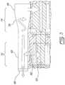
- FIG. 2is a simplified, conceptual sketch showing an example of a scavenge pump
- FIG. 3is a cross-sectional view of the scavenge pump of FIG. 2 , taken across a radially-extending plane;
- FIG. 4A and FIG. 4Bshow the fluid movement between two corresponding positions of a tooth relative to a fluid passage inlet
- FIG. 5is a front elevation view of another example of a scavenge pump
- FIG. 6is a cross-sectional view of the scavenge pump of FIG. 2 , taken across a radially-extending plane;
- FIG. 7is a transversal cross-sectional view taken from FIG. 5 ;
- FIG. 1illustrates a gas turbine engine 10 of a type preferably provided for use in subsonic flight, generally comprising in serial flow communication a fan 12 through which ambient air is propelled, a compressor section 14 for pressurizing the air, a combustor 16 in which the compressed air is mixed with fuel and ignited for generating an annular stream of hot combustion gases, and a turbine section 18 for extracting energy from the combustion gases.
- a gas turbine engine 10of a type preferably provided for use in subsonic flight, generally comprising in serial flow communication a fan 12 through which ambient air is propelled, a compressor section 14 for pressurizing the air, a combustor 16 in which the compressed air is mixed with fuel and ignited for generating an annular stream of hot combustion gases, and a turbine section 18 for extracting energy from the combustion gases.
- the compressor 14 , fan 12 and turbine 18have rotating components which can be mounted on one or more shafts.
- Bearings 20are used to provide smooth relative rotation between a shaft and casing (non-rotating component), and/or between two shafts which rotate at different speeds.
- a scavenge system 30having cavities 32 , conduits 34 , and one or more scavenge pumps 36 , is used to recover the oil, which can be in the form of an oil foam at that stage, from the bearings 20 .
- the pump configurationcan include a separator to fully or partially separate the air from the oil.
- the separatorcan operate on the principle of a vortex driven by the momentum of the fluid which stems from the operation of the pump.
- the vortexcan be parallel to the cavity where the oil is pumped, and housed in the body of the pump itself. If the oil separation is full, the oil can directly be fed to the (main) oil pump, without passing through a reservoir.
- the oil separationis partial, there can be some advantages to separating the oil in this manner, such as reducing the size of the oil tank or achieving separation by consuming less energy, generating less heat, using components which have less weight, and/or using components which are less bulky, for instance.
- FIG. 2schematizes an example of such a pump configuration.
- the pump 40 illustrated in FIG. 2can be seen to generally include a pump body 42 , a main cavity 44 being generally cylindrical in shape, having an inlet 46 and an outlet 48 , and a rotor 50 .
- the rotor 50is rotatably mounted in the main cavity 44 and is configured in a manner to be driven in rotation around a rotor axis 52 .
- the main cavity 44has a curved surface 54 between the inlet 46 and the outlet 48
- the rotor 50has a plurality of pushing members 56 which closely follow the curved surface 54 between the inlet 46 and the outlet 48 during rotation, effectively pushing the fluid therebetween.
- a separator cavity 60is also provided in the pump body 42 , and disposed adjacent the main cavity 44 .
- a fluid passage 62fluidly connects the main cavity 44 to the separator cavity 60 .
- the fluid passage 62is configured to preserve momentum of the fluid as it exits the main cavity, in a manner that the tangential momentum of the fluid which is driven by the movement of the rotor 50 be significantly preserved, and used to drive a vortex in the separator cavity 60 .
- the vortexoccurs around an axis 64 of the separator cavity 60 .
- the momentum of the fluidis the main driving force of the vortex, and the separator cavity is empty except for the liquid/gas mixture, and free from any rotor.
- the fluid passage 62can connect both the main cavity 44 and the separator cavity 60 tangentially, for instance.
- This tangential relationshipdoes not need to be perfect, but orienting the passage off tangential either as it connects the main cavity 44 , or as it connects the separator cavity 60 , past a certain extent, can lead to less than optimal transfer of momentum, and thus a weaker vortex, in the separator cavity 60 .
- the width of the fluid passagecan be of less than half of the radius of the separator cavity 60 , for instance, and perhaps about one quarter of the radius of the separator cavity 60 .
- the separator cavity 60it can be preferred for the separator cavity 60 to have a cylindrical shape, or another solid-of-revolution shape, and a smooth inner surface, in an effort to facilitate and favour the vortex action.
- a first axial end 66 of the separator cavity 60can have an oil outlet, and a second, opposite, axial end 68 of the separator cavity 60 can have an air outlet.
- a portion 70 of the separator cavityradially broadens in the axial direction of the first axial end 66 .
- the helical flow circulating in the conical portionwill naturally reduce its velocity and therefore increase its static pressure, which can be desirable. It was found possible to control the air/oil separation in the separator cavity 60 to a certain extent by adjusting the size (e.g. diameter) of the aperture of the air outlet.
- the separator cavity 60can receive the oil from a first axially-delimited stage 72 acting as a scavenge pump 36 , and a second axially-delimited stage 74 , adjacent the first stage 72 , can receive the separated oil and act as a main oil pump 24 .
- the oilcan be directly fed to the main oil pump, whether this main oil pump is combined as a subsequent stage, or provided as a separate device.
- This configurationis only one possible, optional, example, and the oil outlet can be connected to an entirely distinct main pump, or to an oil tank, in alternate embodiments, to name two examples.
- the primary separation effecthad hardly begun. In the tests performed, it was once the fluid had reached roughly 60 degrees from the inlet that the primary separation was considered to have taken place. This primary separation was found to continue to improve after the first 60 degrees, until it reached roughly 90 degrees, at which stage any further improvement in separation was considered to be negligible. Accordingly, it can be desired to position the inlet of the fluid passage 62 at a location which is at least 50 degrees past the inlet 46 of the main cavity 44 , preferably at least 60 degrees, and perhaps even more preferably at least 70, 80 or even 90 degrees.
- the angle between the main cavity inlet and the fluid passage inletcan be identified as angle ⁇ .
- the pitch of the pushing members 56 of the rotoris related to the pitch of the pushing members 56 of the rotor.
- the rotorhas a plurality of pushing members 56 being circumferentially interspaced from one another by a pitch angle.
- the fluidis “trapped” between successive pushing members 56 only to the extent where the space between the pushing members is not aligned with the inlet 46 or the outlet 48 of the main cavity 44 . Otherwise, there is pressure communication between the space between adjacent pushing members, and the respective one of the inlet 46 and the outlet 48 of the main cavity.
- creating a small radially outward angle as the fluid passage branches off from the curved surface 54could even lead to slightly better performance. Further experimentation may be required to achieve a fuller understanding of the underlying effects associated to such an improvement in performance.
- the air-oil mixtureenters the pump as a homogeneous two-phase fluid.
- the centrifugal forceseparates the oil which collects on the pump housing (curved surface).
- the advancing toothsweeps the oil over the housing.
- the shear force applied by the housing onto the moving oil layerforces the oil to collect in front of the sweeping tooth.
- the oil lumpis discharged as a brief pulse into the narrow channel (fluid passage).
- the narrow channel discharging into the auxiliary conduitwhich acts here as a collector, induces and maintains a vortex in the collector.
- the vortexmay act as a flywheel to smoothen the pressure pulsation originated by the discontinuous oil discharging thus improving the energy recovery and oil separation.
- the vortexseparates the residual air into a bubble in the middle of the collector.
- the airis continuously released by a small relief hole.
- the oilfollows a helical motion in the collector as it is transferred from the scavenge pumps to the main oil pump.
- the helical motionis slowed down in the conical portion according to the moment of momentum conservation law which slowing down leads to increased static pressure at the oil outlet, according to Bernouilli's law.
- FIG. 5illustrates another embodiment.
- the main cavitycan be said to have a first cavity portion 80 housing a first rotor 84 , and a second cavity portion 82 housing a second rotor 86 , the first rotor and the second rotor having teeth and being meshed with each other for torque transmission therebetween, and forming a gear pump.
- a first fluid passagebranches off and bleeds off a tangential fluid flow from the first cavity portion 80 /first rotor, leading to a first separator cavity
- a second fluid passagebranches off and bleeds off a tangential fluid flow from the second cavity portion 82 /second rotor. Both fluid passages can be configured to preserve the momentum of fluid and drive a strong vortex in the corresponding separator cavity.
- the vortex angular orientationcan be the same angular orientation than the rotor angular orientation (e.g. upper rotor in the image), or the vortex angular orientation can be opposite to the angular orientation of the rotor (e.g. lower rotor in the image). It was found that these two different configurations could offer better performances in distinct conditions, and so in practice, it may be preferable to choose the optimal configuration for the specificities of the embodiment (i.e. same angular orientation or opposite angular orientation), and use both auxiliary cavities in the configuration considered optimal for the application (i.e. use a symmetrical design).
- the pumpcan have more than one stage, and that the auxiliary cavities can axially span all the stages and collect vortex-driving momentum from all stages.
- the pumpis a gear pump which has four scavenging stages 90 , 92 , 94 , 96 which each have fluid passages between the main cavity and the corresponding separator cavity.
- the pumphas an additional stage 98 which operates as a main pump.
- an oil outlet of each one of the auxiliary cavitiesis connected to the inlet of the main cavity of the main pump stage.
- the main pumpcan proceed to pump the separated oil to the oil delivery system 22 .
Landscapes
- Engineering & Computer Science (AREA)
- Mechanical Engineering (AREA)
- General Engineering & Computer Science (AREA)
- Chemical & Material Sciences (AREA)
- Combustion & Propulsion (AREA)
- Life Sciences & Earth Sciences (AREA)
- Sustainable Development (AREA)
- Details And Applications Of Rotary Liquid Pumps (AREA)
Abstract
Description
Claims (20)
Priority Applications (2)
| Application Number | Priority Date | Filing Date | Title |
|---|---|---|---|
| US16/254,800US11162494B2 (en) | 2019-01-23 | 2019-01-23 | Scavenge pump |
| CA3068970ACA3068970A1 (en) | 2019-01-23 | 2020-01-17 | Scavenge pump |
Applications Claiming Priority (1)
| Application Number | Priority Date | Filing Date | Title |
|---|---|---|---|
| US16/254,800US11162494B2 (en) | 2019-01-23 | 2019-01-23 | Scavenge pump |
Publications (2)
| Publication Number | Publication Date |
|---|---|
| US20200232388A1 US20200232388A1 (en) | 2020-07-23 |
| US11162494B2true US11162494B2 (en) | 2021-11-02 |
Family
ID=71609712
Family Applications (1)
| Application Number | Title | Priority Date | Filing Date |
|---|---|---|---|
| US16/254,800Active2039-09-14US11162494B2 (en) | 2019-01-23 | 2019-01-23 | Scavenge pump |
Country Status (2)
| Country | Link |
|---|---|
| US (1) | US11162494B2 (en) |
| CA (1) | CA3068970A1 (en) |
Cited By (1)
| Publication number | Priority date | Publication date | Assignee | Title |
|---|---|---|---|---|
| US12352209B1 (en) | 2024-06-25 | 2025-07-08 | Pratt & Whitney Canada Corp. | Aircraft engine fluid separation system and method |
Families Citing this family (1)
| Publication number | Priority date | Publication date | Assignee | Title |
|---|---|---|---|---|
| CN114412643B (en)* | 2022-01-25 | 2024-08-06 | 中国航发贵阳发动机设计研究所 | Multi-stage oil return device integrating oil-gas separation function |
Citations (58)
| Publication number | Priority date | Publication date | Assignee | Title |
|---|---|---|---|---|
| US3692432A (en)* | 1970-12-22 | 1972-09-19 | Ford Motor Co | Two-stage positive displacement pump |
| US4322231A (en) | 1980-06-16 | 1982-03-30 | Farr Company | Filter element locking mechanism |
| US4355964A (en)* | 1980-08-22 | 1982-10-26 | Caterpillar Tractor Co. | Gear pump having fluid deaeration capability |
| US4480970A (en)* | 1981-05-30 | 1984-11-06 | Rolls-Royce Limited | Self priming gear pump |
| US4525995A (en)* | 1983-04-04 | 1985-07-02 | Williams International Corporation | Oil scavening system for gas turbine engine |
| US4536200A (en) | 1983-10-03 | 1985-08-20 | Reist Parker C | Gas filter apparatus and method of filtering |
| US4631009A (en)* | 1984-07-18 | 1986-12-23 | Sundstrand Corporation | Lubrication scavenge system |
| US4707165A (en) | 1985-03-04 | 1987-11-17 | Aeroquip Corporation | Gas and fluid separator |
| US4715244A (en) | 1986-07-17 | 1987-12-29 | Sundstrand Corporation | Self-scavenging gear box lubrication system |
| US5004407A (en)* | 1989-09-26 | 1991-04-02 | Sundstrand Corporation | Method of scavenging air and oil and gear pump therefor |
| US5085561A (en) | 1989-12-12 | 1992-02-04 | Mitsubishi Oil Co., Ltd. | Gas removal pump for liquid |
| US5531129A (en) | 1994-09-21 | 1996-07-02 | Synectic Technology, Inc. | Apparatus for extracting wear particles from used oil filters |
| US6149703A (en) | 1999-06-10 | 2000-11-21 | Siemens Westinghouse Power Corporation | Fuel system filtering apparatus |
| US6398833B1 (en) | 2000-11-06 | 2002-06-04 | Pratt & Whitney Canada Corp. | Air/oil separator |
| US20030037757A1 (en)* | 2001-08-24 | 2003-02-27 | Osband Lance Ian | Osband super inductionexhaustion valveshaft' engine system, V-type, flat-type, single-type, multi-cylinder four-cycle engine(s) |
| US6533845B2 (en) | 1999-11-10 | 2003-03-18 | Donaldson Company, Inc. | Filter arrangement and methods |
| US6991665B1 (en) | 2004-02-06 | 2006-01-31 | Graver Technologies, Inc. | Evertible filter wrap with straps |
| US20060102428A1 (en)* | 2004-11-15 | 2006-05-18 | Aisin Seiki Kabushiki Kaisha | Lubrication apparatus |
| US7124662B2 (en)* | 2004-01-30 | 2006-10-24 | Pratt & Whitney Canada Corp. | Reversible driving apparatus for PCU pumps |
| US20060257267A1 (en)* | 2005-05-13 | 2006-11-16 | Wade Weiss | Pump system for an automotive engine |
| US20070178003A1 (en)* | 2005-11-22 | 2007-08-02 | Parker-Hannifin Corporation | Gear pump with ripple chamber for low noise and pressure ripples |
| US7396376B2 (en) | 2003-12-22 | 2008-07-08 | Donaldson Company, Inc. | Seal arrangement for filter element; filter element assembly; and, methods |
| US7532969B2 (en)* | 2006-03-09 | 2009-05-12 | Pratt & Whitney Canada Corp. | Gas turbine speed detection |
| US20110277442A1 (en) | 2010-05-12 | 2011-11-17 | General Electric Company | Seal for Gas Turbine Filter |
| US8114196B2 (en) | 2009-08-31 | 2012-02-14 | General Electric Company | Gas turbine inlet filter house cleaning apparatus and method |
| US8201664B2 (en) | 2008-01-23 | 2012-06-19 | Pratt & Whitney Canada Corp. | Lubrication system and method, and vortex flow separator for use therewith |
| US20120240535A1 (en) | 2011-03-22 | 2012-09-27 | General Electric Company | Filter retaining apparatus |
| US8357219B2 (en) | 2005-10-11 | 2013-01-22 | Donaldson Company, Inc. | Air filter arrangement; assembly and methods |
| US20130121854A1 (en)* | 2011-11-10 | 2013-05-16 | Gkn Walterscheid Gmbh | Gearbox |
| US8529668B2 (en) | 2012-01-13 | 2013-09-10 | Hamilton Sundstrand Corporation | Deaerator outlet diffuser |
| US8545589B2 (en) | 2007-06-26 | 2013-10-01 | Donaldson Company, Inc. | Filtration media pack, filter element, and methods |
| US20130323104A1 (en)* | 2012-05-31 | 2013-12-05 | Daniel Alecu | Scavenge gear pump |
| US8601785B2 (en)* | 2010-06-23 | 2013-12-10 | Pratt & Whitney Canada Corp. | Oil supply system with main pump deaeration |
| US8702373B1 (en)* | 2013-07-15 | 2014-04-22 | United Technologies Corporation | Lubrication of journal bearing during clockwise and counter-clockwise rotation |
| US8734572B2 (en) | 2012-04-03 | 2014-05-27 | Bha Altair, Llc | Quick engagement method for gas turbine inlet filter installation and replacement |
| US8845898B2 (en) | 2010-07-07 | 2014-09-30 | Hamilton Sundstrand Corporation | APU fuel filter housing scupper |
| US8973760B2 (en) | 2010-10-01 | 2015-03-10 | Advanced Filtration Systems, Inc | Filter system with fuel-water separator |
| WO2015153906A2 (en) | 2014-04-04 | 2015-10-08 | Donaldson Company, Inc. | Filter elements with end cap features; element support assembly; and methods |
| US20150337731A1 (en)* | 2013-01-18 | 2015-11-26 | United Technologies Corporation | Oil pump transfer plate |
| US20150343346A1 (en)* | 2014-05-28 | 2015-12-03 | United Technologies Corporation | Scavenge filter system for a gas turbine engine |
| US9260980B2 (en) | 2011-03-17 | 2016-02-16 | Rolls-Royce Plc | Rotating fluid pumping system |
| US9308483B2 (en) | 2011-06-03 | 2016-04-12 | Aaf Ltd. | Filter assembly |
| US9446333B2 (en) | 2013-02-07 | 2016-09-20 | Parker-Hannifin Corporation | Keyed thread engagement on spin-on filter element |
| US20170107872A1 (en)* | 2015-10-15 | 2017-04-20 | GM Global Technology Operations LLC | Lubricating fluid system for a vehicle with self compensation plate |
| US9782702B2 (en) | 2014-05-22 | 2017-10-10 | Pall Corporation | Filter assemblies, filter elements, and methods for filtering liquids |
| US9795914B2 (en) | 2014-05-09 | 2017-10-24 | Rolls-Royce Deutschland Ltd & Co Kg | Device of an aircraft engine for separating oil from an air-oil volume flow |
| US20180119617A1 (en) | 2016-10-31 | 2018-05-03 | Pratt & Whitney Canada Corp. | Centrifugal separator |
| US10024239B2 (en) | 2015-07-22 | 2018-07-17 | Pratt & Whitney Canada Corp. | Fuel filter and bypass valve arrangement |
| US10201772B2 (en) | 2016-01-22 | 2019-02-12 | Caterpillar Inc. | Filter element and filter system |
| US10247102B2 (en) | 2013-06-12 | 2019-04-02 | United Technologies Corporation | Fuel/oil manifold |
| US20190162182A1 (en)* | 2017-11-28 | 2019-05-30 | GM Global Technology Operations LLC | Gear Pump That Removes Air From Pumped Oil |
| US20190162063A1 (en)* | 2017-03-17 | 2019-05-30 | Halliburton Energy Services, Inc. | Electric submersible pump gas separator |
| US10337600B2 (en) | 2015-06-30 | 2019-07-02 | Sikorsky Aircraft Corporation | Scalable in-situ gear box and powertrain lubricant monitoring systems and methods |
| US20190249537A1 (en)* | 2017-08-30 | 2019-08-15 | Halliburton Energy Services, Inc. | Crossover system and apparatus for an electric submersible gas separator |
| US20190345853A1 (en) | 2018-05-08 | 2019-11-14 | United Technologies Corporation | Centrifugal debris pre-separator for turbine engine oil filter |
| US10512865B2 (en) | 2017-02-06 | 2019-12-24 | Bha Altair, Llc | Devices and methods for aligning filters in a holding frame |
| US20200141223A1 (en)* | 2017-08-30 | 2020-05-07 | Halliburton Energy Services, Inc. | Crossover System and Apparatus for an Electric Submersible Gas Separator |
| US20210054840A1 (en)* | 2019-08-19 | 2021-02-25 | Progress Rail Locomotive Inc. | Oil pump for an aged engine |
- 2019
- 2019-01-23USUS16/254,800patent/US11162494B2/enactiveActive
- 2020
- 2020-01-17CACA3068970Apatent/CA3068970A1/enactivePending
Patent Citations (63)
| Publication number | Priority date | Publication date | Assignee | Title |
|---|---|---|---|---|
| US3692432A (en)* | 1970-12-22 | 1972-09-19 | Ford Motor Co | Two-stage positive displacement pump |
| GB1336344A (en)* | 1970-12-22 | 1973-11-07 | Ford Motor Co | Positive displacement pump |
| US4322231A (en) | 1980-06-16 | 1982-03-30 | Farr Company | Filter element locking mechanism |
| US4355964A (en)* | 1980-08-22 | 1982-10-26 | Caterpillar Tractor Co. | Gear pump having fluid deaeration capability |
| US4480970A (en)* | 1981-05-30 | 1984-11-06 | Rolls-Royce Limited | Self priming gear pump |
| US4525995A (en)* | 1983-04-04 | 1985-07-02 | Williams International Corporation | Oil scavening system for gas turbine engine |
| US4536200A (en) | 1983-10-03 | 1985-08-20 | Reist Parker C | Gas filter apparatus and method of filtering |
| US4631009A (en)* | 1984-07-18 | 1986-12-23 | Sundstrand Corporation | Lubrication scavenge system |
| US4707165A (en) | 1985-03-04 | 1987-11-17 | Aeroquip Corporation | Gas and fluid separator |
| US4715244A (en) | 1986-07-17 | 1987-12-29 | Sundstrand Corporation | Self-scavenging gear box lubrication system |
| US5004407A (en)* | 1989-09-26 | 1991-04-02 | Sundstrand Corporation | Method of scavenging air and oil and gear pump therefor |
| US5085561A (en) | 1989-12-12 | 1992-02-04 | Mitsubishi Oil Co., Ltd. | Gas removal pump for liquid |
| US5531129A (en) | 1994-09-21 | 1996-07-02 | Synectic Technology, Inc. | Apparatus for extracting wear particles from used oil filters |
| US6149703A (en) | 1999-06-10 | 2000-11-21 | Siemens Westinghouse Power Corporation | Fuel system filtering apparatus |
| US6533845B2 (en) | 1999-11-10 | 2003-03-18 | Donaldson Company, Inc. | Filter arrangement and methods |
| US6398833B1 (en) | 2000-11-06 | 2002-06-04 | Pratt & Whitney Canada Corp. | Air/oil separator |
| US20030037757A1 (en)* | 2001-08-24 | 2003-02-27 | Osband Lance Ian | Osband super inductionexhaustion valveshaft' engine system, V-type, flat-type, single-type, multi-cylinder four-cycle engine(s) |
| US7396376B2 (en) | 2003-12-22 | 2008-07-08 | Donaldson Company, Inc. | Seal arrangement for filter element; filter element assembly; and, methods |
| US7124662B2 (en)* | 2004-01-30 | 2006-10-24 | Pratt & Whitney Canada Corp. | Reversible driving apparatus for PCU pumps |
| US6991665B1 (en) | 2004-02-06 | 2006-01-31 | Graver Technologies, Inc. | Evertible filter wrap with straps |
| US20060102428A1 (en)* | 2004-11-15 | 2006-05-18 | Aisin Seiki Kabushiki Kaisha | Lubrication apparatus |
| US20060257267A1 (en)* | 2005-05-13 | 2006-11-16 | Wade Weiss | Pump system for an automotive engine |
| US8357219B2 (en) | 2005-10-11 | 2013-01-22 | Donaldson Company, Inc. | Air filter arrangement; assembly and methods |
| US20070178003A1 (en)* | 2005-11-22 | 2007-08-02 | Parker-Hannifin Corporation | Gear pump with ripple chamber for low noise and pressure ripples |
| US7532969B2 (en)* | 2006-03-09 | 2009-05-12 | Pratt & Whitney Canada Corp. | Gas turbine speed detection |
| US8545589B2 (en) | 2007-06-26 | 2013-10-01 | Donaldson Company, Inc. | Filtration media pack, filter element, and methods |
| US8201664B2 (en) | 2008-01-23 | 2012-06-19 | Pratt & Whitney Canada Corp. | Lubrication system and method, and vortex flow separator for use therewith |
| US8114196B2 (en) | 2009-08-31 | 2012-02-14 | General Electric Company | Gas turbine inlet filter house cleaning apparatus and method |
| US20110277442A1 (en) | 2010-05-12 | 2011-11-17 | General Electric Company | Seal for Gas Turbine Filter |
| US8601785B2 (en)* | 2010-06-23 | 2013-12-10 | Pratt & Whitney Canada Corp. | Oil supply system with main pump deaeration |
| US8845898B2 (en) | 2010-07-07 | 2014-09-30 | Hamilton Sundstrand Corporation | APU fuel filter housing scupper |
| US8973760B2 (en) | 2010-10-01 | 2015-03-10 | Advanced Filtration Systems, Inc | Filter system with fuel-water separator |
| US9260980B2 (en) | 2011-03-17 | 2016-02-16 | Rolls-Royce Plc | Rotating fluid pumping system |
| US20120240535A1 (en) | 2011-03-22 | 2012-09-27 | General Electric Company | Filter retaining apparatus |
| US9308483B2 (en) | 2011-06-03 | 2016-04-12 | Aaf Ltd. | Filter assembly |
| US20130121854A1 (en)* | 2011-11-10 | 2013-05-16 | Gkn Walterscheid Gmbh | Gearbox |
| US8529668B2 (en) | 2012-01-13 | 2013-09-10 | Hamilton Sundstrand Corporation | Deaerator outlet diffuser |
| US8734572B2 (en) | 2012-04-03 | 2014-05-27 | Bha Altair, Llc | Quick engagement method for gas turbine inlet filter installation and replacement |
| US9033690B2 (en)* | 2012-05-31 | 2015-05-19 | Pratt & Whitney Canada Corp. | Scavenge gear pump |
| US20130323104A1 (en)* | 2012-05-31 | 2013-12-05 | Daniel Alecu | Scavenge gear pump |
| US20150337731A1 (en)* | 2013-01-18 | 2015-11-26 | United Technologies Corporation | Oil pump transfer plate |
| US9446333B2 (en) | 2013-02-07 | 2016-09-20 | Parker-Hannifin Corporation | Keyed thread engagement on spin-on filter element |
| US10247102B2 (en) | 2013-06-12 | 2019-04-02 | United Technologies Corporation | Fuel/oil manifold |
| US8702373B1 (en)* | 2013-07-15 | 2014-04-22 | United Technologies Corporation | Lubrication of journal bearing during clockwise and counter-clockwise rotation |
| US10577974B2 (en)* | 2013-07-15 | 2020-03-03 | United Technologies Corporation | Lubrication of journal bearing during clockwise and counter-clockwise rotation |
| US20160146048A1 (en)* | 2013-07-15 | 2016-05-26 | United Technologies Corporation | Lubrication of journal bearing during clockwise and counter-clockwise rotation |
| US20190383168A1 (en)* | 2013-07-15 | 2019-12-19 | United Technologies Corporation | Lubrication of journal bearing during clockwise and counter-clockwise rotation |
| WO2015153906A2 (en) | 2014-04-04 | 2015-10-08 | Donaldson Company, Inc. | Filter elements with end cap features; element support assembly; and methods |
| US9795914B2 (en) | 2014-05-09 | 2017-10-24 | Rolls-Royce Deutschland Ltd & Co Kg | Device of an aircraft engine for separating oil from an air-oil volume flow |
| US9782702B2 (en) | 2014-05-22 | 2017-10-10 | Pall Corporation | Filter assemblies, filter elements, and methods for filtering liquids |
| US20150343346A1 (en)* | 2014-05-28 | 2015-12-03 | United Technologies Corporation | Scavenge filter system for a gas turbine engine |
| US10337600B2 (en) | 2015-06-30 | 2019-07-02 | Sikorsky Aircraft Corporation | Scalable in-situ gear box and powertrain lubricant monitoring systems and methods |
| US10024239B2 (en) | 2015-07-22 | 2018-07-17 | Pratt & Whitney Canada Corp. | Fuel filter and bypass valve arrangement |
| US20170107872A1 (en)* | 2015-10-15 | 2017-04-20 | GM Global Technology Operations LLC | Lubricating fluid system for a vehicle with self compensation plate |
| US10201772B2 (en) | 2016-01-22 | 2019-02-12 | Caterpillar Inc. | Filter element and filter system |
| US20180119617A1 (en) | 2016-10-31 | 2018-05-03 | Pratt & Whitney Canada Corp. | Centrifugal separator |
| US10512865B2 (en) | 2017-02-06 | 2019-12-24 | Bha Altair, Llc | Devices and methods for aligning filters in a holding frame |
| US20190162063A1 (en)* | 2017-03-17 | 2019-05-30 | Halliburton Energy Services, Inc. | Electric submersible pump gas separator |
| US20190249537A1 (en)* | 2017-08-30 | 2019-08-15 | Halliburton Energy Services, Inc. | Crossover system and apparatus for an electric submersible gas separator |
| US20200141223A1 (en)* | 2017-08-30 | 2020-05-07 | Halliburton Energy Services, Inc. | Crossover System and Apparatus for an Electric Submersible Gas Separator |
| US20190162182A1 (en)* | 2017-11-28 | 2019-05-30 | GM Global Technology Operations LLC | Gear Pump That Removes Air From Pumped Oil |
| US20190345853A1 (en) | 2018-05-08 | 2019-11-14 | United Technologies Corporation | Centrifugal debris pre-separator for turbine engine oil filter |
| US20210054840A1 (en)* | 2019-08-19 | 2021-02-25 | Progress Rail Locomotive Inc. | Oil pump for an aged engine |
Cited By (1)
| Publication number | Priority date | Publication date | Assignee | Title |
|---|---|---|---|---|
| US12352209B1 (en) | 2024-06-25 | 2025-07-08 | Pratt & Whitney Canada Corp. | Aircraft engine fluid separation system and method |
Also Published As
| Publication number | Publication date |
|---|---|
| CA3068970A1 (en) | 2020-07-23 |
| US20200232388A1 (en) | 2020-07-23 |
Similar Documents
| Publication | Publication Date | Title |
|---|---|---|
| US10729992B2 (en) | Centrifugal separator | |
| EP3309371B1 (en) | Gear train architecture for a multi-spool gas turbine engine | |
| EP1653064B1 (en) | Gas turbine engine with counter rotating blades | |
| US10502143B2 (en) | Compressor of axial turbine engine with contra-rotating rotor | |
| EP3273032B1 (en) | A multi-spool gas turbine engine architecture | |
| EP3339610A1 (en) | Multi-spool gas turbine engine architecture | |
| EP3199782A1 (en) | Geared gas turbine engine | |
| US20160032825A1 (en) | Gas turbine engine with supersonic compressor | |
| EP3321488A1 (en) | Gas turbine engine accessories arrangement | |
| EP3020953B1 (en) | Gas turbine engine | |
| CN212296627U (en) | gas turbine engine | |
| US11162494B2 (en) | Scavenge pump | |
| CA2970386A1 (en) | A multi-spool gas turbine engine architecture | |
| JP2019211080A (en) | Lubrication system and method for lubricating geared architecture | |
| CN111322158A (en) | Ice crystal protection for gas turbine engines | |
| CN106285948A (en) | Gas-turbine unit | |
| CN110700891A (en) | Turbine engine compressor | |
| US11608782B2 (en) | Axial inertial particle separator for turbine engine | |
| US12330089B2 (en) | Dynamic deaeration system | |
| US11261789B2 (en) | Inertial particle separator for turbine engine | |
| CN111608953A (en) | Ice crystal protection for gas turbine engines | |
| CN111237252A (en) | Fan blade retention assembly | |
| CN107923310A (en) | Compound cycle engine | |
| CN111473235B (en) | Oil removal system | |
| CN107923309A (en) | Compound cycle engine |
Legal Events
| Date | Code | Title | Description |
|---|---|---|---|
| FEPP | Fee payment procedure | Free format text:ENTITY STATUS SET TO UNDISCOUNTED (ORIGINAL EVENT CODE: BIG.); ENTITY STATUS OF PATENT OWNER: LARGE ENTITY | |
| AS | Assignment | Owner name:PRATT & WHITNEY CANADA CORP., CANADA Free format text:ASSIGNMENT OF ASSIGNORS INTEREST;ASSIGNORS:ALECU, DANIEL;CUTRARA, SAM;REEL/FRAME:048117/0511 Effective date:20190114 | |
| STPP | Information on status: patent application and granting procedure in general | Free format text:NON FINAL ACTION MAILED | |
| STPP | Information on status: patent application and granting procedure in general | Free format text:RESPONSE TO NON-FINAL OFFICE ACTION ENTERED AND FORWARDED TO EXAMINER | |
| STPP | Information on status: patent application and granting procedure in general | Free format text:NOTICE OF ALLOWANCE MAILED -- APPLICATION RECEIVED IN OFFICE OF PUBLICATIONS | |
| STPP | Information on status: patent application and granting procedure in general | Free format text:PUBLICATIONS -- ISSUE FEE PAYMENT VERIFIED | |
| STCF | Information on status: patent grant | Free format text:PATENTED CASE | |
| MAFP | Maintenance fee payment | Free format text:PAYMENT OF MAINTENANCE FEE, 4TH YEAR, LARGE ENTITY (ORIGINAL EVENT CODE: M1551); ENTITY STATUS OF PATENT OWNER: LARGE ENTITY Year of fee payment:4 |