US11160970B2 - Fluid seals for catheter pump motor assembly - Google Patents
Fluid seals for catheter pump motor assemblyDownload PDFInfo
- Publication number
- US11160970B2 US11160970B2US15/654,402US201715654402AUS11160970B2US 11160970 B2US11160970 B2US 11160970B2US 201715654402 AUS201715654402 AUS 201715654402AUS 11160970 B2US11160970 B2US 11160970B2
- Authority
- US
- United States
- Prior art keywords
- fluid
- motor
- assembly
- impeller
- pump system
- Prior art date
- Legal status (The legal status is an assumption and is not a legal conclusion. Google has not performed a legal analysis and makes no representation as to the accuracy of the status listed.)
- Active, expires
Links
Images


Classifications
- A—HUMAN NECESSITIES
- A61—MEDICAL OR VETERINARY SCIENCE; HYGIENE
- A61M—DEVICES FOR INTRODUCING MEDIA INTO, OR ONTO, THE BODY; DEVICES FOR TRANSDUCING BODY MEDIA OR FOR TAKING MEDIA FROM THE BODY; DEVICES FOR PRODUCING OR ENDING SLEEP OR STUPOR
- A61M60/00—Blood pumps; Devices for mechanical circulatory actuation; Balloon pumps for circulatory assistance
- A61M60/40—Details relating to driving
- A61M60/403—Details relating to driving for non-positive displacement blood pumps
- A61M60/408—Details relating to driving for non-positive displacement blood pumps the force acting on the blood contacting member being mechanical, e.g. transmitted by a shaft or cable
- A61M60/411—Details relating to driving for non-positive displacement blood pumps the force acting on the blood contacting member being mechanical, e.g. transmitted by a shaft or cable generated by an electromotor
- A61M60/414—Details relating to driving for non-positive displacement blood pumps the force acting on the blood contacting member being mechanical, e.g. transmitted by a shaft or cable generated by an electromotor transmitted by a rotating cable, e.g. for blood pumps mounted on a catheter
- A—HUMAN NECESSITIES
- A61—MEDICAL OR VETERINARY SCIENCE; HYGIENE
- A61M—DEVICES FOR INTRODUCING MEDIA INTO, OR ONTO, THE BODY; DEVICES FOR TRANSDUCING BODY MEDIA OR FOR TAKING MEDIA FROM THE BODY; DEVICES FOR PRODUCING OR ENDING SLEEP OR STUPOR
- A61M60/00—Blood pumps; Devices for mechanical circulatory actuation; Balloon pumps for circulatory assistance
- A61M60/80—Constructional details other than related to driving
- A61M60/802—Constructional details other than related to driving of non-positive displacement blood pumps
- A61M60/827—Sealings between moving parts
- A61M60/829—Sealings between moving parts having a purge fluid supply
- A—HUMAN NECESSITIES
- A61—MEDICAL OR VETERINARY SCIENCE; HYGIENE
- A61M—DEVICES FOR INTRODUCING MEDIA INTO, OR ONTO, THE BODY; DEVICES FOR TRANSDUCING BODY MEDIA OR FOR TAKING MEDIA FROM THE BODY; DEVICES FOR PRODUCING OR ENDING SLEEP OR STUPOR
- A61M25/00—Catheters; Hollow probes
- A61M25/0021—Catheters; Hollow probes characterised by the form of the tubing
- A61M25/0023—Catheters; Hollow probes characterised by the form of the tubing by the form of the lumen, e.g. cross-section, variable diameter
- A61M25/0026—Multi-lumen catheters with stationary elements
- A—HUMAN NECESSITIES
- A61—MEDICAL OR VETERINARY SCIENCE; HYGIENE
- A61M—DEVICES FOR INTRODUCING MEDIA INTO, OR ONTO, THE BODY; DEVICES FOR TRANSDUCING BODY MEDIA OR FOR TAKING MEDIA FROM THE BODY; DEVICES FOR PRODUCING OR ENDING SLEEP OR STUPOR
- A61M60/00—Blood pumps; Devices for mechanical circulatory actuation; Balloon pumps for circulatory assistance
- A61M60/10—Location thereof with respect to the patient's body
- A61M60/122—Implantable pumps or pumping devices, i.e. the blood being pumped inside the patient's body
- A61M60/126—Implantable pumps or pumping devices, i.e. the blood being pumped inside the patient's body implantable via, into, inside, in line, branching on, or around a blood vessel
- A61M60/13—Implantable pumps or pumping devices, i.e. the blood being pumped inside the patient's body implantable via, into, inside, in line, branching on, or around a blood vessel by means of a catheter allowing explantation, e.g. catheter pumps temporarily introduced via the vascular system
- A—HUMAN NECESSITIES
- A61—MEDICAL OR VETERINARY SCIENCE; HYGIENE
- A61M—DEVICES FOR INTRODUCING MEDIA INTO, OR ONTO, THE BODY; DEVICES FOR TRANSDUCING BODY MEDIA OR FOR TAKING MEDIA FROM THE BODY; DEVICES FOR PRODUCING OR ENDING SLEEP OR STUPOR
- A61M60/00—Blood pumps; Devices for mechanical circulatory actuation; Balloon pumps for circulatory assistance
- A61M60/10—Location thereof with respect to the patient's body
- A61M60/122—Implantable pumps or pumping devices, i.e. the blood being pumped inside the patient's body
- A61M60/126—Implantable pumps or pumping devices, i.e. the blood being pumped inside the patient's body implantable via, into, inside, in line, branching on, or around a blood vessel
- A61M60/135—Implantable pumps or pumping devices, i.e. the blood being pumped inside the patient's body implantable via, into, inside, in line, branching on, or around a blood vessel inside a blood vessel, e.g. using grafting
- A—HUMAN NECESSITIES
- A61—MEDICAL OR VETERINARY SCIENCE; HYGIENE
- A61M—DEVICES FOR INTRODUCING MEDIA INTO, OR ONTO, THE BODY; DEVICES FOR TRANSDUCING BODY MEDIA OR FOR TAKING MEDIA FROM THE BODY; DEVICES FOR PRODUCING OR ENDING SLEEP OR STUPOR
- A61M60/00—Blood pumps; Devices for mechanical circulatory actuation; Balloon pumps for circulatory assistance
- A61M60/20—Type thereof
- A61M60/205—Non-positive displacement blood pumps
- A61M60/216—Non-positive displacement blood pumps including a rotating member acting on the blood, e.g. impeller
- A—HUMAN NECESSITIES
- A61—MEDICAL OR VETERINARY SCIENCE; HYGIENE
- A61M—DEVICES FOR INTRODUCING MEDIA INTO, OR ONTO, THE BODY; DEVICES FOR TRANSDUCING BODY MEDIA OR FOR TAKING MEDIA FROM THE BODY; DEVICES FOR PRODUCING OR ENDING SLEEP OR STUPOR
- A61M60/00—Blood pumps; Devices for mechanical circulatory actuation; Balloon pumps for circulatory assistance
- A61M60/40—Details relating to driving
- A61M60/403—Details relating to driving for non-positive displacement blood pumps
- A61M60/422—Details relating to driving for non-positive displacement blood pumps the force acting on the blood contacting member being electromagnetic, e.g. using canned motor pumps
- A—HUMAN NECESSITIES
- A61—MEDICAL OR VETERINARY SCIENCE; HYGIENE
- A61M—DEVICES FOR INTRODUCING MEDIA INTO, OR ONTO, THE BODY; DEVICES FOR TRANSDUCING BODY MEDIA OR FOR TAKING MEDIA FROM THE BODY; DEVICES FOR PRODUCING OR ENDING SLEEP OR STUPOR
- A61M60/00—Blood pumps; Devices for mechanical circulatory actuation; Balloon pumps for circulatory assistance
- A61M60/80—Constructional details other than related to driving
- A61M60/802—Constructional details other than related to driving of non-positive displacement blood pumps
- A61M60/804—Impellers
- A61M60/806—Vanes or blades
- A61M60/808—Vanes or blades specially adapted for deformable impellers, e.g. expandable impellers
- A—HUMAN NECESSITIES
- A61—MEDICAL OR VETERINARY SCIENCE; HYGIENE
- A61M—DEVICES FOR INTRODUCING MEDIA INTO, OR ONTO, THE BODY; DEVICES FOR TRANSDUCING BODY MEDIA OR FOR TAKING MEDIA FROM THE BODY; DEVICES FOR PRODUCING OR ENDING SLEEP OR STUPOR
- A61M60/00—Blood pumps; Devices for mechanical circulatory actuation; Balloon pumps for circulatory assistance
- A61M60/80—Constructional details other than related to driving
- A61M60/855—Constructional details other than related to driving of implantable pumps or pumping devices
- A61M60/871—Energy supply devices; Converters therefor
- A—HUMAN NECESSITIES
- A61—MEDICAL OR VETERINARY SCIENCE; HYGIENE
- A61M—DEVICES FOR INTRODUCING MEDIA INTO, OR ONTO, THE BODY; DEVICES FOR TRANSDUCING BODY MEDIA OR FOR TAKING MEDIA FROM THE BODY; DEVICES FOR PRODUCING OR ENDING SLEEP OR STUPOR
- A61M25/00—Catheters; Hollow probes
- A61M25/0067—Catheters; Hollow probes characterised by the distal end, e.g. tips
- A61M25/0074—Dynamic characteristics of the catheter tip, e.g. openable, closable, expandable or deformable
- A61M2025/0079—Separate user-activated means, e.g. guidewires, guide tubes, balloon catheters or sheaths, for sealing off an orifice, e.g. a lumen or side holes, of a catheter
- A—HUMAN NECESSITIES
- A61—MEDICAL OR VETERINARY SCIENCE; HYGIENE
- A61M—DEVICES FOR INTRODUCING MEDIA INTO, OR ONTO, THE BODY; DEVICES FOR TRANSDUCING BODY MEDIA OR FOR TAKING MEDIA FROM THE BODY; DEVICES FOR PRODUCING OR ENDING SLEEP OR STUPOR
- A61M25/00—Catheters; Hollow probes
- A61M25/10—Balloon catheters
- A61M25/1018—Balloon inflating or inflation-control devices
- A61M2025/1022—Balloon inflating or inflation-control devices driven by a rotary motor-activated pump
Definitions
- This applicationis directed to catheter pumps for mechanical circulatory support of a heart.
- Heart diseaseis a major health problem that has high mortality rate. Physicians increasingly use mechanical circulatory support systems for treating heart failure. The treatment of acute heart failure requires a device that can provide support to the patient quickly. Physicians desire treatment options that can be deployed quickly and minimally-invasively.
- MCSMechanical circulatory support
- VADsventricular assist devices
- MIacute myocardial infarction
- PCIpercutaneous coronary intervention
- An example of an MCS systemis a rotary blood pump placed percutaneously, e.g., via a catheter.
- a blood pumpis inserted into the body and connected to the cardiovascular system, for example, to the left ventricle and the ascending aorta to assist the pumping function of the heart.
- Other known applicationsinclude placing the pump in the descending aorta, a peripheral artery, and the like.
- acute circulatory support devicesare used to reduce the afterload on the heart muscle and provide blood flow for a period of time to stabilize the patient prior to heart transplant or for continuing support.
- a heart pumpthat can be placed minimally-invasively, for example, through an 18FR, 14FR, or 8FR incision. In one aspect, there is a need for a heart pump that can provide an average flow rate of 4 Lpm or more during operation, for example, at 62 mmHg of aortic pressure.
- VADspercutaneous ventricular assist devices
- Some percutaneous VADsare designed to rotate at speeds of more than 15,000 RPM, and in some cases more than 25,000 RPM in operation.
- the vibration, noise, and heat from the motor and driveshaftcan cause discomfort to the patient, especially when positioned inside the body.
- fluidssuch as saline and/or blood
- may enter the motorwhich can damage the motor and/or impair operation of the catheter pump. Accordingly, there is a need for a device that improves performance and patient comfort with a high speed motor.
- a motorconfigured to drive an operative device, e.g., an impeller, atherectomy device, or other rotating feature
- an improved motorwith sealing between each end.
- a motorcapable of rotating at relatively high speeds and providing sealing between a wet side and an electrical side.
- a catheter pump systemin one embodiment, can include a shaft assembly and an impeller coupled with a distal portion of the shaft assembly.
- the catheter pump systemcan include a motor assembly comprising a motor configured to impart rotation to the impeller through the shaft assembly.
- the catheter pump systemcan include a fluid pathway for supplying a fluid from outside the body, the fluid pathway conveying at least a portion of the supplied fluid proximally during operation of the catheter pump system.
- the catheter pump systemcan include a seal disposed between the motor assembly and the impeller, the seal configured to impede the fluid conveyed proximally in the fluid pathway by the impeller from entering the motor assembly at least about an outer periphery of the shaft assembly, the seal comprising an opening through which a portion of the shaft assembly extends.
- the shaft assemblycomprises an output shaft coupled with the motor and a drive shaft coupled with the impeller, a distal portion of the output shaft coupled with a proximal portion of the drive shaft.
- a motor couplingcan mechanically connect the proximal portion of the drive shaft with the distal portion of the output shaft.
- the motor couplingcan comprise an opening having at least one flat surface, wherein at least one of the output shaft and the drive shaft is fitted in the opening.
- a second sealcan be disposed between the motor assembly and the impeller, the second seal configured to further impede or prevent the fluid conveyed proximally in the fluid pathway from entering the motor assembly at least about the outer periphery of the shaft assembly.
- a barriercan separate the motor assembly from a majority of the proximally-conveyed fluid, wherein the seal is disposed distal and adjacent the barrier, and wherein the second seal is disposed proximal and adjacent the barrier.
- the barriercan comprise a proximal portion of a flow diverter housing through which the proximally-conveyed fluid flows.
- the shaft assemblycan comprise a lumen therethrough, the lumen passing through the motor.
- the lumencan pass through the catheter pump system from a distal end of the catheter pump system to a proximal end of the catheter pump system.
- the lumencan comprise a portion of the fluid pathway such that at least some of the fluid passes through the lumen.
- the catheter pump systemcan include a guidewire guide tube disposed in the lumen, the guidewire guide tube configured to receive a guidewire therein for guiding the impeller to a target site of a patient.
- the shaft assemblyextends through at least a portion of the motor, through the opening of the seal, and to the impeller.
- the motorcan comprise a direct drive electric motor, e.g., a motor without any gear reduction and/or a clutch.
- the motorcan comprise a rotor and a stator assembly disposed about the rotor.
- the rotorcan be disposed in a chamber, and wherein the seal prevents or impedes the proximally-flowing fluid from entering the chamber.
- the catheter pump systemcan include an insulating coating over the shaft assembly to electrically separate the shaft assembly from a patient.
- the sealcan comprise a lip seal disposed about the shaft assembly, the lip seal biased radially inward to bear against the outer periphery of the shaft assembly.
- the sealcomprises a flange which converts axial fluid pressure to radially inward pressure to further bear against the outer periphery of the shaft assembly.
- the catheter pump systemcan include a chamber, the seal disposed in the chamber, the chamber defining a portion of the fluid pathway.
- a catheter assemblycan be disposed between the motor assembly and the impeller, the catheter assembly defining at least a portion of the fluid pathway.
- the fluid pathwaycan comprise a first channel configured to permit the supplied fluid to flow from proximally to distally in the catheter assembly and a second channel that conveys the at least a portion of the supplied fluid proximally along the shaft assembly.
- the catheter pump systemcan include a cannula in which the impeller is disposed, the cannula and impeller expandable from a stored configuration to a deployed configuration.
- a catheter pump systemcan include a shaft assembly and an impeller coupled with a distal portion of the shaft assembly.
- the catheter pump systemcan include a motor assembly that imparts rotation on the impeller through the shaft assembly, the motor assembly comprising a motor that rotates the shaft assembly, the shaft assembly comprising an output shaft portion through the motor, the output shaft portion comprising a motor lumen.
- the catheter pump systemcan include a fluid pathway for supplying a fluid from outside the body, the fluid pathway conveying at least a portion of the supplied fluid proximally during operation of the catheter pump system.
- the catheter pump systemcan include a seal disposed between the motor assembly and the impeller, the seal configured to impede or prevent the fluid from the fluid pathway from entering the motor assembly at least about an outer periphery of the shaft assembly.
- the sealcomprises an opening through which a portion of the shaft assembly extends.
- the shaft assemblycan further comprise a drive shaft portion coupled with the impeller, a distal portion of the output shaft portion coupled with a proximal portion of the drive shaft portion.
- the shaft assemblycan comprise a guidewire guide lumen therethrough, the guidewire guide lumen comprising the motor lumen, wherein the guidewire guide lumen passes through the catheter pump system from a distal end of the catheter pump system to a proximal end of the catheter pump system.
- the lumencan define a portion of the fluid pathway such that at least some of the fluid passes through the lumen.
- the catheter pump systemcan include a guidewire guide tube disposed in the lumen, the guidewire guide tube configured to receive a guidewire therein for guiding the impeller to a target site of a patient.
- a second sealcan be disposed between the motor assembly and the impeller, the second seal configured to further impede or prevent the fluid from the fluid pathway from entering the motor assembly at least about the outer periphery of the shaft assembly.
- a barriercan separate the motor assembly from a majority of the proximally-conveyed fluid, wherein the seal is disposed distal and adjacent the barrier, and wherein the second seal can be disposed proximal and adjacent the barrier.
- An insulating coatingcan be disposed over the shaft assembly to electrically separate the shaft assembly from a patient.
- the sealcan comprise a lip seal disposed about the shaft assembly, the lip seal biased radially inward to bear against the outer periphery of the shaft assembly.
- the sealcan comprise a flange which converts axial fluid pressure to radially inward pressure to further bear against the outer periphery of the shaft assembly.
- the catheter pump systemcan include a flow diverter comprising a chamber, the seal disposed in the chamber, the chamber defining a portion of the fluid pathway.
- a first channelcan be configured to permit fluid to flow from proximally to distally in the catheter pump system and a second channel can convey the at least a portion of the supplied fluid proximally.
- a method of operating a pumpcomprising an impeller and a motor assembly comprising a motor coupled with the impeller.
- the methodcan include rotating a shaft assembly with the motor to impart rotation to the impeller.
- the methodcan include directing fluid into the pump from outside the body, at least a portion of the fluid flowing back proximally along a fluid pathway between the impeller and the motor assembly.
- the methodcan include impeding the fluid from entering the motor assembly at least about an outer periphery of the shaft assembly with a seal, the seal comprising an opening through which a portion of the shaft assembly extends.
- the methodcan include directing at least some of the fluid through a lumen extending through an output shaft portion of the shaft assembly, the output shaft portion passing through the motor.
- the methodcan include inserting a guidewire through the lumen, and advancing the pump over the guidewire to a target site in a patient.
- the methodcan include expanding the impeller from a stored configuration to a deployed configuration.
- a catheter pump systemcan include a shaft assembly and an impeller coupled with a distal portion of the shaft assembly.
- the catheter pump systemcan include a motor assembly that imparts rotation on the impeller through the shaft assembly, the motor assembly comprising a motor that rotates the shaft assembly, the shaft assembly comprising an output shaft portion through the motor, the output shaft portion comprising a motor lumen.
- the catheter pump systemcan include a fluid pathway that conveys fluid proximally during operation of the catheter pump system, the fluid pathway comprising a first fluid pathway comprising a conduit that directs a first portion of the fluid to bypass the motor assembly and a second fluid pathway that directs a second portion of the fluid through the motor lumen, the conduit connecting with the fluid pathway at a position distal the motor assembly.
- the catheter pump systemcan include a seal disposed between the motor assembly and the position, the seal configured to impede or prevent the fluid from the fluid pathway from entering the motor assembly at least about an outer periphery of the shaft assembly, the seal comprising an opening through which a portion of the shaft assembly extends.
- a catheter pump systemcan include an impeller and a catheter body having a lumen in which fluid flows proximally therethrough during operation of the catheter pump.
- the catheter pump systemcan include a drive shaft disposed inside the catheter body and coupled with the impeller at a distal portion of the drive shaft, the drive shaft configured such that rotation of the drive shaft causes the impeller to rotate.
- the catheter pump systemcan include a motor assembly.
- the motor assemblycan include a chamber, at least a portion of the chamber in fluid communication with the lumen of the catheter body.
- the motor assemblycan also include a rotor disposed in the at least a portion of the chamber, the rotor mechanically coupled with a proximal portion of the drive shaft such that rotation of the rotor causes the drive shaft to rotate.
- the motor assemblycan include a stator assembly disposed about the rotor and configured to cause the rotor to rotate. No cooling fins extend outside an exterior surface of the motor assembly.
- a catheter pump systemin another embodiment, can include an impeller and a catheter body having a lumen therethrough, the impeller mechanically coupled with a distal portion of the catheter body.
- the catheter pump systemcan include a guidewire guide tube disposed through the lumen from a proximal portion of the catheter pump to a distal portion of the catheter pump, the guidewire guide tube configured to receive a guidewire therein.
- the catheter pump systemcan include an end cap secured to a proximal end portion of the guide tube, the end cap configured such that axial movement of the end cap relative to the catheter body causes the guidewire guide tube to be removed from the catheter pump.
- the catheter pump systemcan include a resealable closure device disposed at a proximal portion of the catheter pump, the closure device configured such that when the guidewire guide tube is removed from the catheter pump, the closure device encloses the proximal portion of the catheter pump system.
- a catheter pump systemin another embodiment, can include a pump including an impeller for pumping blood.
- the catheter pump systemcan include a motor assembly for imparting rotation on the impeller through a drive shaft.
- the motor assemblycan comprise a stator carrying electrical windings and a rotor disposed in at least a portion of the stator, the rotor mechanically coupled with a proximal portion of the drive shaft.
- the catheter pump systemcan include a fluid supply system for delivering fluid to the pump during operation of the pump and returning at least some of the supplied fluid to a waste reservoir.
- the fluid supply systemcan comprise a fluid channel extending within the stator and a fluid pathway which passes outside the stator. During operation of the pump, at least a first portion of the returning fluid can pass through the fluid channel and at least a second portion of the returning fluid can pass through the fluid pathway.
- a method of operating a pumpcan comprise a motor which includes a stator assembly having windings and a rotor positioned within the stator assembly.
- the methodcan include rotating the rotor by selectively energizing the windings.
- the methodcan include cooling the motor by flowing a first fluid portion between the stator assembly and the rotor and by flowing a second fluid portion outside the stator.
- FIG. 1Aillustrates one embodiment of a catheter pump system with an impeller assembly configured for percutaneous application and operation.
- FIG. 1Bis a schematic view of one embodiment of a catheter pump system adapted to be used in the manner illustrated in FIG. 1A .
- FIG. 1Cis a schematic view of another embodiment of a catheter pump system.
- FIG. 2is a side plan view of a motor assembly of the catheter pump system shown in FIG. 1B , according to various embodiments.
- FIG. 3is a perspective exploded view of the motor assembly shown in FIG. 2 .
- FIG. 4Ais a side cross-sectional view of the motor assembly shown in FIGS. 2-3 .
- FIG. 4Bis a side cross-sectional view of a motor assembly, according to another embodiment.
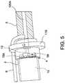
- FIG. 5is a schematic perspective view of an interface between a distal chamber and a rotor chamber of a flow diverter of the motor assembly, with a stator assembly thereof hidden for ease of illustration.
- FIG. 6Ais a schematic perspective view of an interface between an output shaft of the motor assembly and a drive shaft of the catheter pump system.
- FIG. 6Bis a cross-sectional perspective view, taken through the longitudinal axis of the catheter, showing the interface shown in FIG. 6A .
- FIG. 7is an image of a cap and a female receiver, with the guide tube not shown.
- FIG. 8Ais a schematic perspective view of a motor assembly, according to another embodiment.
- FIG. 8Bis a schematic perspective exploded view of the motor assembly of FIG. 8A .
- FIG. 8Cis a schematic side view of the motor assembly of FIGS. 8A-8B .
- FIG. 8Dis a schematic side sectional, exploded view of the motor assembly shown in FIG. 8C .
- FIG. 8Eis a schematic side sectional view of the motor assembly shown in FIGS. 8A-8D .
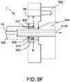
- FIG. 8Fis a magnified schematic side sectional view of the motor assembly shown in FIG. 8E .
- FIG. 8Gis a schematic side sectional view of the seal shown in FIGS. 8A-8F .
- FIG. 9Ais a schematic perspective view of a motor assembly, according to another embodiment.
- FIG. 9Bis a schematic side cross-sectional view of the motor assembly of FIG. 9A .
- This applicationis generally directed to apparatuses for inducing motion of a fluid relative to the apparatus.
- Exemplars of circulatory support systems for treating heart failure, and in particular emergent and/or acute heart failureare disclosed in U.S. Pat. Nos. 4,625,712; 4,686,982; 4,747,406; 4,895,557; 4,944,722; 6,176,848; 6,926,662; 7,022,100; 7,393,181; 7,841,976; 8,157,719; 8,489,190; 8,597,170; 8,721,517 and U.S. Pub. Nos. 2012/0178986 and 2014/0010686, the entire contents of which patents and publications are incorporated by reference for all purposes.
- an impellercan be coupled at a distal portion of the apparatus.
- the motoris a brushless DC (BLDC) motor.
- the motoris a micro BLDC motor.
- BLDCbrushless DC
- the motoris a micro BLDC motor.
- Some embodimentsgenerally relate to various configurations for a motor assembly adapted to drive an impeller at a distal end of a catheter pump, e.g., a percutaneous heart pump.
- the motor described hereinmay be used for other applications including catheter-based devices like an atherectomy device. In such applications, the disclosed motor assembly is disposed outside the patient in some embodiments. In other embodiments, the disclosed motor assembly and/or features of the motor are miniaturized and sized to be inserted within the body, e.g., within the vasculature.
- FIGS. 1A-1Bshow aspects of an exemplary catheter pump 100 A that can provide relatively high blood flow rates (i.e. full or near full blood flow).
- the pump 100 Aincludes a motor assembly 1 driven by a console 122 , which can include an electronic controller and various fluid handling systems.
- the console 122directs the operation of the motor 1 and an infusion system that supplies a flow of fluid in the pump 100 A. Additional details regarding the exemplary console 122 may be understood from U.S. Patent Publication No. US 2014/0275725, the contents of which are incorporated by reference herein in their entirety and for all purposes.
- the pump 100 Aincludes a catheter assembly 101 that can be coupled with the motor assembly 1 and can house an impeller in an impeller assembly 116 A within a distal portion of the catheter assembly 101 of the pump 100 A.
- the impelleris rotated remotely by the motor 1 when the pump 100 A is operating.
- the motor 1can be disposed outside the patient.
- the motor 1is separate from the console 122 , e.g., to be placed closer to the patient.
- the pumpis placed in the patient in a sterile environment and the console is outside the sterile environment.
- the motoris disposed on the sterile side of the system.
- the motor 1is part of the console 122 .
- FIG. 1Cis a schematic view of another embodiment of a catheter pump system.
- FIG. 1Cis similar to FIG. 1B , except the motor 1 is miniaturized for insertion into the body.
- the motor 1can be disposed proximal the impeller assembly 116 A.
- the motor 1can be generally similar to the motor assembly shown in FIG. 2 , except the motor 1 is sized and shaped to be inserted into the patient's vasculature.
- One or more electrical linesmay extend from the motor to the console outside the patient. The electrical lines can send signals for controlling the operation of the motor.
- Such embodimentsallow a drive shaft coupled with the impeller and disposed within the catheter assembly 101 to be much shorter, e.g., shorter than the distance from the aortic valve to the aortic arch (about 5 cm or less).
- Various embodiments of the motor assembly 1are disclosed herein, including embodiments having a rotor disposed within a stator assembly.
- waste fluidcan pass through a housing in which the rotor is disposed to help cool the motor assembly 1 .
- the housing in which the motor 1 of FIG. 1C is disposedcan be sealed from fluids (e.g., blood and/or saline) so as to isolate the electrical lines from the fluids.
- fluidse.g., blood and/or saline
- one or more sealscan be provided to impede or prevent the flow of liquids into the housing.
- FIG. 1Aillustrates one use of the catheter pump 100 A.
- a distal portion of the pump 100 A including a catheter assembly including the impeller assembly 116 Ais placed in the left ventricle (LV) of the heart to pump blood from the LV into the aorta.
- the pump 100 Acan be used in this way to treat a wide range of heart failure patient populations including, but not limited to, cardiogenic shock (such as acute myocardial infarction, acute decompensated heart failure, or postcardiotomy), myocarditis, and others.
- the pumpcan also be used for various other indications including to support a patient during a cardiac invention such as a high-risk percutaneous coronary intervention (PCI) or ablation.
- PCIpercutaneous coronary intervention
- One convenient manner of placement of the distal portion of the pump 100 A in the heartis by percutaneous access and delivery using a modified Seldinger technique or other methods familiar to cardiologists. These approaches enable the pump 100 A to be used in emergency medicine, a catheter lab and in other medical settings. Modifications can also enable the pump 100 A to support the right side of the heart. Example modifications that could be used for right side support include providing delivery features and/or shaping a distal portion that is to be placed through at least one heart valve from the venous side, such as is discussed in U.S. Pat. Nos. 6,544,216; 7,070,555; and US 2012-0203056A1, all of which are hereby incorporated by reference herein in their entirety for all purposes.
- the impeller assembly 116 A(e.g., the impeller and cannula) can be expandable and collapsible. In the collapsed state, the distal end of the catheter pump 100 A can be advanced to the heart, for example, through an artery. In the expanded state the impeller assembly 116 A is able to pump blood at relatively high flow rates.
- the expandable cannula and impeller configurationallows for decoupling of the insertion size and flow rate, in other words, it allows for higher flow rates than would be possible through a lumen limited to the insertion size with all other things being equal.
- FIGS. 1A and 1Bthe impeller assembly 116 A is illustrated in the expanded state.
- the collapsed statecan be provided by advancing a distal end 170 A of an elongate body 174 A distally over the impeller assembly 116 A to cause the impeller assembly 116 A to collapse.
- Thisprovides an outer profile throughout the catheter assembly and catheter pump 100 A that is of small diameter during insertion, for example, to a catheter size of about 12.5 FR in various arrangements.
- the impeller assembly 116 Ais not expandable.
- the mechanical components rotatably supporting the impeller within the impeller assembly 116 Apermit relatively high rotational speeds while controlling heat and particle generation that can come with high speeds.
- the infusion systemdelivers a cooling and lubricating solution to the distal portion of the catheter pump 100 A for these purposes.
- the space for delivery of this fluidis extremely limited. Some of the space is also used for return of the fluid as waste fluid. Providing secure connection and reliable routing of fluid into and out of the catheter pump 100 A is critical and challenging in view of the small profile of the catheter assembly 101 .
- the catheter pump 100 AWhen activated, the catheter pump 100 A can effectively support, restore and/or increase the flow of blood out of the heart and through the patient's vascular system.
- the pump 100 Acan be configured to produce a maximum flow rate (e.g. zero mm Hg backpressure) of greater than 4 Lpm, greater than 4.5 Lpm, greater than 5 Lpm, greater than 5.5 Lpm, greater than 6 Lpm, greater than 6.5 Lpm, greater than 7 Lpm, greater than 7.5 Lpm, greater than 8 Lpm, greater than 9 Lpm, or greater than 10 Lpm.
- a maximum flow ratee.g. zero mm Hg backpressure
- the pump 100 Acan be configured to produce an average flow rate at 62 mmHg of greater than 2 Lpm, greater than 2.5 Lpm, greater than 3 Lpm, greater than 3.5 Lpm, greater than 4 Lpm, greater than 4.25 Lpm, greater than 4.5 Lpm, greater than 5 Lpm, greater than 5.5 Lpm, greater than 6 Lpm, greater than 6.5 Lpm, greater than 7 Lpm, greater than 8 Lpm, or greater than 9 Lpm.
- a priming apparatus 1400can be disposed over the impeller assembly 116 A.
- the impeller assembly 116 Acan include an expandable cannula or housing and an impeller with one or more blades. As the impeller rotates, blood can be pumped proximally (or distally in some implementations) to function as a cardiac assist device.
- the pumpis configured to be primed with fluid.
- a priming apparatus 1400can be disposed over the impeller assembly 116 A near the distal end portion 170 A of the elongate body 174 A.
- the priming apparatus 1400can be used in connection with a procedure to expel air from the impeller assembly 116 A, e.g., any air that is trapped within the housing or that remains within the elongate body 174 A near the distal end 170 A.
- the priming proceduremay be performed before the pump is inserted into the patient's vascular system, so that air bubbles are not allowed to enter and/or injure the patient.
- the priming apparatus 1400can include a primer housing 1401 configured to be disposed around both the elongate body 174 A and the impeller assembly 116 A.
- a sealing cap 1406can be applied to the proximal end 1402 of the primer housing 1401 to substantially seal the priming apparatus 1400 for priming, i.e., so that air does not proximally enter the elongate body 174 A and also so that priming fluid does not flow out of the proximal end of the housing 1401 .
- the sealing cap 1406can couple to the primer housing 1401 in any way known to a skilled artisan.
- the sealing cap 1406is threaded onto the primer housing by way of a threaded connector 1405 located at the proximal end 1402 of the primer housing 1401 .
- the sealing cap 1406can include a sealing recess disposed at the distal end of the sealing cap 1406 .
- the sealing recesscan be configured to allow the elongate body 174 A to pass through the sealing cap 1406 .
- the priming operationcan proceed by introducing fluid into the sealed priming apparatus 1400 to expel air from the impeller assembly 116 A and the elongate body 174 A.
- Fluidcan be introduced into the priming apparatus 1400 in a variety of ways.
- fluidcan be introduced distally through the elongate body 174 A into the priming apparatus 1400 .
- an inletsuch as a luer
- a gas permeable membranecan be disposed on a distal end 1404 of the primer housing 1401 . The gas permeable membrane can permit air to escape from the primer housing 1401 during priming.
- the priming apparatus 1400also can advantageously be configured to collapse an expandable portion of the catheter pump 100 A.
- the primer housing 1401can include a funnel 1415 where the inner diameter of the housing decreases from distal to proximal.
- the funnelmay be gently curved such that relative proximal movement of the impeller housing causes the impeller housing to be collapsed by the funnel 1415 .
- the distal end 170 A of the elongate body 174 Acan be moved distally relative to the collapsed housing.
- the catheter pump 100 Acan be removed from the priming apparatus 1400 before a percutaneous heart procedure is performed, e.g., before the pump 100 A is activated to pump blood.
- the embodiments disclosed hereinmay be implemented such that the total time for infusing the system is minimized or reduced.
- the time to fully infuse the systemcan be about six minutes or less.
- the time to infusecan be about three minutes or less.
- the total time to infuse the systemcan be about 45 seconds or less. It should be appreciated that lower times to infuse can be advantageous for use with cardiovascular patients.
- the described pumpis primed with fluid, one will appreciate from the description herein that the priming may be optional.
- the pumpcan be prepared such that all air is removed before it is packaged. In another example, air is removed by placing the pump under vacuum.
- the elongate body 174 Aextends from the impeller assembly 116 A in a proximal direction to an fluid supply device 195 .
- the fluid supply device 195is configured to allow for fluid to enter the catheter assembly 101 of the catheter pump 100 A and/or for waste fluid to leave the catheter assembly 101 of the catheter pump 100 A.
- a catheter body 120 A(which also passes through the elongate body 174 A) can extend proximally and couple to the motor assembly 1 .
- the motor assembly 1can provide torque to a drive shaft that extends from the motor assembly 1 through the catheter body 120 A to couple to an impeller shaft at or proximal to the impeller assembly 116 A.
- the catheter body 120 Acan pass within the elongate body 174 A such that the external elongate body 174 A can axially translate relative to the internal catheter body 120 A.
- a fluid supply line 6can fluidly couple with the console 122 to supply saline or other fluid to the catheter pump 100 A.
- the saline or other fluidcan pass through an internal lumen of the internal catheter body 120 A and can provide lubrication to the impeller assembly 116 A and/or chemicals to the patient.
- the supplied fluide.g., saline, dextrose, glucose solution, or infusate
- the fluidis supplied to the patient at a flow rate in a range of 15 mL/hr to 50 mL/hr, or more particularly, in a range of 20 mL/hr to 40 mL/hr, or more particularly, in a range of 25 mL/hr to 35 mL/hr.
- One or more electrical conduits 124can provide electrical communication between the console 122 and the motor assembly 1 .
- a controller within the console 122can control the operation of the motor assembly 1 during use.
- Fluide.g., saline
- the fluidcan be provided from outside the patient (e.g., by way of one or more supply bags) to the pump through a supply lumen in the catheter body.
- the fluidcan return to the motor assembly 1 by way of a lumen (e.g., a central or interior lumen) of the catheter body.
- a waste line 7can extend from the motor assembly 1 to a waste reservoir 126 . Waste fluid from the catheter pump 100 A can pass through the motor assembly 1 and out to the reservoir 126 by way of the waste line 7 .
- the waste fluidflows to the motor assembly 1 and the reservoir 126 at a flow rate which is lower than that at which the fluid is supplied to the patient.
- some of the supplied fluidmay flow out of the catheter body 120 A and into the patient by way of one or more bearings.
- the waste fluid(e.g., a portion of the fluid which passes proximally back through the motor from the patient) may flow through the motor assembly 1 at any suitable flow rate, e.g., at a flow rate in a range of 5 mL/hr to 20 mL/hr, or more particularly, in a range of 10 mL/hr to 15 mL/hr.
- the pump and motorbe configured to operate without fluid flushing.
- One purpose of the fluid supplyis to cool the motor.
- a micromotordimensioned and configured to be inserted percutaneously, there may not be a need for fluid cooling because the motor heat will be dissipated by the body.
- Accesscan be provided to a proximal end of the catheter assembly 101 of the catheter pump 100 A prior to or during use.
- the catheter assembly 101is delivered over a guidewire 235 .
- the guidewire 235may be conveniently extended through the entire length of the catheter assembly 101 of the catheter pump 100 A and out of a proximal end 1455 of the catheter assembly 101 .
- the connection between the motor assembly 1 and the catheter assembly 101is configured to be permanent, such that the catheter pump, the motor housing and the motor are disposable components.
- the coupling between the motor housing and the catheter assembly 101is disengageable, such that the motor and motor housing can be decoupled from the catheter assembly 101 after use.
- the catheter assembly 101 distal of the motorcan be disposable, and the motor and motor housing can be re-usable.
- FIG. 1Billustrates the guidewire 235 extending from a proximal guidewire opening 237 in the motor assembly 1 .
- a clinicianmay insert the guidewire 235 through the patient's vascular system to the heart to prepare a path for the impeller assembly 116 A to the heart.
- the catheter pump 100 Acan include a guidewire guide tube 20 (see FIG. 3 ) passing through a central internal lumen of the catheter pump 100 A from the proximal guidewire opening 237 .
- the guidewire guide tube 20can be pre-installed in the catheter pump 100 A to provide the clinician with a preformed pathway along which to insert the guidewire 235 .
- the guidewire 235is placed into a peripheral blood vessel, and along the path between that blood vessel and the heart and into a heart chamber, e.g., into the left ventricle. Thereafter, a distal end opening of the catheter pump 100 A and guidewire guide tube 20 can be advanced over the proximal end of the guidewire 235 to enable delivery of the catheter pump 100 A. After the proximal end of the guidewire 235 is urged proximally within the catheter pump 100 A and emerges from the guidewire opening 237 and/or guidewire guide tube 20 , the catheter pump 100 A can be advanced into the patient. In one method, the guidewire guide tube 20 is withdrawn proximally while holding the catheter pump 100 A.
- the cliniciancan insert the guidewire 235 through the proximal guidewire opening 237 and urge the guidewire 235 along the guidewire guide tube.
- the cliniciancan continue urging the guidewire 235 through the patient's vascular system until the distal end of the guidewire 235 is positioned in the desired position, e.g., in a chamber of the patient's heart, a major blood vessel or other source of blood.
- a proximal end portion of the guidewire 235can extend from the proximal guidewire opening 237 .
- the cliniciancan maneuver the impeller assembly 116 A over the guidewire 235 until the impeller assembly 116 A reaches the distal end of the guidewire 235 in the heart, blood vessel or other source of blood.
- the cliniciancan remove the guidewire 235 and the guidewire guide tube.
- the guidewire guide tubecan also be removed before or after the guidewire 235 is removed in some implementations.
- the cliniciancan activate the motor 1 to rotate the impeller and begin operation of the pump 100 A.
- catheter pump 100 Ais configured to be inserted using a modified Seldinger technique.
- the pumpmay be configured with a lumen therethrough for receiving a guidewire.
- the guidewireis threaded through the pump without a guidewire guide tube.
- Other configurationsmay be employed for loading the pump onto a guidewire and/or moving the pump to the target location in the body. Examples of similar techniques are described in U.S. Pat. No. 7,022,100 and U.S. Pub. No. 2005/0113631, the entire contents of which patent and publication are incorporated herein for all purposes.
- FIGS. 2 and 3further illustrate aspects of embodiments of the motor assembly 1 shown in FIG. 1B .
- the motor assembly 1can include a stator assembly 2 ( FIGS. 2-3 ) and a rotor 15 disposed radially within the stator assembly 2 ( FIG. 3 ).
- the motor assembly 1also includes a flow diverter 3 , which can be configured as a manifold for directing fluid through one or more passages in the catheter pump 100 A. In some cases, the flow diverter 3 is at least partially disposed radially between the stator assembly 2 and the rotor 15 ( FIGS. 2-3 ).
- the flow diverter 3can be fluidly sealed about the rotor 15 and a proximal portion 56 of the catheter body 120 A.
- the sealprevents leakage and also can prevent the fluid from contacting the stator assembly 2 .
- the flow diverter 3can include a distal chamber 5 within which the proximal portion 56 of the catheter body 120 A is disposed and a rotor chamber 4 within which the rotor 15 is disposed.
- the distal chamber 5is fluidly connected with the catheter.
- the rotor chamber 4is fluidly connected with the waste line 7 .
- the flow diverter 3can also have a proximal chamber 10 in some embodiments. Where provided, the distal chamber 5 , rotor chamber 4 , and proximal chamber 10 can be in fluid communication within the flow diverter 3 .
- One or more flanges 11 A, 11 Bcan mechanically couple the flow diverter 3 to an external housing (not shown).
- the flanges 11 A, 11 Bare examples of mount structures that can be provided, which can include in various embodiments dampers to isolate the motor assembly 1 from external shock or vibration.
- mount structurescan include dampers configured to isolate an outer housing or the environment external to the motor assembly 1 from shock or vibration generated by the motor assembly 1 .
- an optional pressure sensor assembly 12is configured to measure the pressure at a distal portion of the catheter pump 100 A by, for example, measuring the pressure of a column of fluid that extends distally through a lumen of the catheter body 120 A.
- the guidewire guide tube 20can extend proximally through the motor assembly 1 and can terminate at a tube end cap 8 . As explained above, the guidewire 235 can be inserted within the guide tube 20 for guiding the catheter pump 100 A to the heart.
- the rotor 15 and stator assembly 2are configured as or are components of a frameless-style motor for driving the impeller assembly 116 A at the distal end of the pump 100 A.
- the stator assembly 2can comprise a stator and a plurality of conductive windings producing a controlled magnetic field. The windings can be wrapped about or in a stationary portion 65 of the stator assembly 2 .
- the rotor 15can comprise a magnetic material, e.g., can include one or more permanent magnets.
- the rotor 15can comprise a multi-pole magnet, e.g., a four-pole or six-pole magnet.
- the console 122can provide electrical power (e.g., 24V) to the stator assembly 2 to drive the motor assembly 1 .
- One or more leads 9can electrically communicate with the stator assembly 2 , e.g., with one or more Hall sensors used to detect the speed and/or position of the motor. In other embodiments, other sensors (e.g., optical sensors) can be used to measure motor speed.
- the rotor 15can be secured to an output shaft 13 (which can comprise a hollow shaft with a central lumen) such that rotation of the rotor 15 causes the output shaft 13 to rotate.
- the motor assembly 1can comprise a direct current (DC) brushless motor.
- DCdirect current
- other types of motorscan be used, such as AC motors, gearhead motor, etc.
- first and second journal bearings 18 A, 18 Bcan be provided about the output shaft 13 to radially and/or longitudinally center the output shaft 13 and thereby the rotor 15 relative to the stator assembly 2 .
- FIG. 4Ashows that the output shaft 13 (which is secured to the rotor 15 ) can be mechanically coupled with the proximal end portion of a drive shaft 16 .
- the drive shaft 16extends distally through an internal lumen of the catheter body 120 A.
- a distal end portion of the drive shaft 16is mechanically connected with the impeller.
- rotation of the rotor 15causes the output shaft 13 to rotate, which, in turn, causes the drive shaft 16 and the impeller to rotate.
- FIG. 4Aalso shows that a lumen 55 can extend through the output shaft 13 and the rotor 15 .
- the lumen 55is coupled with a lumen of the catheter body 120 A such that the guidewire guide tube 20 can extend through the lumen 55 within the rotor 15 and into the lumen of the catheter body 120 A.
- the drive shaft 16comprises a braided shaft having an internal lumen. The braided drive shaft 16 or cable can be permeable to liquid such that supply fluid or waste fluid can flow from outside the drive shaft 16 to within the internal lumen of the drive shaft 16 (and vice versa).
- FIG. 4Ashows the tube end cap 8 welded or otherwise secured to a proximal end portion of the guide tube 20 .
- the cap 8can be removably engaged (e.g., screwed or otherwise removably locked) over a female receiver 71 that is secured in a proximal end of the proximal chamber 10 .
- the proximal end of the female receiver 71can be disposed in a counterbore of the cap 8 , while the guide tube 20 extends through the central opening of the cap 8 .
- one or more tabs of the receiver 71can be rotated such that the tab(s) slide under a corresponding tab in the counterbore of the cap 8 .
- FIG. 7shows one embodiment of the cap 8 and of the female receiver 71 that can be coupled with the guide tube 20 (not shown).
- the cap 8can be fixed to the guide tube 20 ; in other embodiments, the receiver 71 can be fixed to the guide tube 20 .
- Engaging the cap 8 to the receiver 71can advantageously prevent the guide tube 20 from accidentally being removed from or slid within the catheter pump 100 A, e.g., if the patient or clinician impacts the cap 8 .
- the cliniciancan disengage the cap 8 from the receiver 71 and can pull the guide tube 20 from the catheter pump 100 A, for example, by pulling proximally on the end cap 8 .
- a resealable septum 72e.g., a resealable closure member
- the septum 72will naturally reseal the pathway proximally from the motor assembly 1 such that fluid does not exit the assembly 1 .
- cap 8is locked and will not be dislodged without rotating and unlocking cap 8 from receiver 71 . Otherwise, the cap 8 can slide axially if it is inadvertently bumped by the patient or clinician. This potentially results in the guide tube 20 being pulled out from the distal-most end of the impeller assembly 116 A, and because the guide tube cannot be re-inserted, the clinician either has to use the catheter pump 100 A without a guide or get a new pump.
- an external surface of an external housing of the motor assembly 1may be kept at or below this temperature.
- regulatory guidelinescan require that no part in contact with skin exceed 40° C.
- various strategies for heat managementare employed by the inventions described herein.
- coolingrefers to transferring away or dissipating heat, and in certain respects, cooling is used interchangeably with removing heat. In some embodiments, however, the fluids passing through or around the motor assembly 1 may not be utilized for cooling purposes.
- Various components of the motor assembly 1generate heat.
- moving parts within the motor assembly 1e.g., the rotating output shaft 13 and/or drive shaft 16
- heatcan be generated by the electrical current flowing through the stator assembly 2 and/or by induction heating caused by conductive components inside a rotating magnetic field.
- friction between the bearings 18 A, 18 B and the output shaft 13 and/or friction between the drive shaft 16 and the inner wall of catheter body 120 Amay also generate undesirable heat in the motor assembly. Inadequate cooling can result in temperature increases of the motor assembly 1 , which can present patient discomfort, health risks, or performance losses.
- various embodiments disclosed hereincan advantageously transfer away generated heat and cool the motor assembly 1 such that the operating temperature of the assembly 1 is sufficiently low to avoid such complexities of use or operation and/or other components of the system.
- various heat transfer componentscan be used to move heat away from thermal generation sources and away from the patient.
- Various aspects of the illustrated device hereinare designed to reduce the risk of hot spots, reduce the risk of heat spikes, and/or improve heat dissipation to the environment and away from the patient.
- the catheter pumpmakes use of the fluid supply system already embedded in the pump to cool the motor assembly 1 and housing.
- heat absorbing capacity of fluid flowing through the flow diverter 3is used to cool the motor assembly 1 .
- the supply line 6can supply fluid 35 from a source (e.g., a fluid bag) to an outer lumen 57 of the catheter body 120 A.
- the supplied fluid 35can travel distally toward the impeller assembly 116 A to lubricate rotating components in the catheter assembly 101 and/or supply fluid to the patient.
- a seal 19e.g., an o-ring
- backflowis flow of fluid 35 proximally into the distal chamber 5 rather than distally within the lumen 57 .
- Such flowis to be prevented to ensure that the fluid 35 is initially exposed to moving parts in a distal portion of the catheter assembly 101 to lubricate and cool such distal components.
- Fluid from the catheter pump 100 Acan flow proximally through an inner lumen 58 of the catheter body 120 A.
- some or all of the supplied fluid 35can flow within the drive shaft 16 and/or around the periphery of the drive shaft 16 .
- some or all of the supplied fluid 35can flow in a space disposed radially between the drive shaft 16 and the catheter body 120 A.
- the proximally-flowing fluidcan flow along a flow pathway which removes heat from the motor assembly 1 . As shown in FIG. 4A , the proximally-flowing fluid (or other cooling fluid) can flow into the rotor chamber 4 of the flow diverter 3 .
- a first portion 17 A of the waste fluidcan pass proximally through the motor assembly 1 about a periphery of the rotor 15 , e.g., in a gap between the rotor 15 and a wall of the flow diverter 3 .
- a second portion 17 B of the waste fluidcan pass proximally through the motor assembly 1 through the lumen 55 of the output shaft 13 .
- the fluid portions 17 A, 17 Bcan pass from the rotor chamber 4 into the proximal chamber 10 of the flow diverter 3 , where the fluid 17 A, 17 B can flow out to a reservoir (not shown) by way of line 7 .
- the embodiment of FIG. 4Acan advantageously convey heat from the heat generating components (e.g., rotor 15 and stator assembly 2 ) into the fluid 35 or other cooling fluid and to the reservoir 126 by way of the waste line 7 .
- the first portion 17 A of the fluid that passes about the periphery of the rotor 15can direct heat radially outward from the rotor 15 and other components of the flow diverter 3 .
- the first portion 17 A of the fluid that passes about the periphery of the rotor 15can direct heat inward from the stator assembly 2 and other components outside the flow diverter 3 .
- the second portion 17 B of the waste fluidcan draw heat radially inward, e.g., radially inward from the rotor 15 and other components of the flow diverter 3 .
- the temperature of the motor housingcan be reduced or maintained at a suitable operational temperature for the medical staff, the patient and/or for the catheter pump system.
- a gap between the stator assembly and the external motor housinge.g., the outer shell or housing surrounding the motor assembly
- FIG. 4Bis a side cross-sectional view of a motor assembly 1 , according to another embodiment.
- components numbered similar to those in FIG. 4Arepresent the same or similar components and functionalities.
- a first portion 17 A of the fluidcan pass proximally through the motor assembly 1 about a periphery of the rotor 15 , e.g., in a gap between the rotor 15 and a wall of the flow diverter 3 .
- a second portion 17 B of the fluidcan pass proximally through the motor assembly 1 through the lumen 55 of the output shaft 13 .
- the fluid portions 17 A, 17 Bcan pass from the rotor chamber 4 into the proximal chamber 10 of the flow diverter 3 , where the fluid 17 A, 17 B can flow out to a reservoir (not shown) by way of line 7 .
- the fluid portions 17 A, 17 Bcan flow along a first fluid pathway or channel within the flow diverter 3 which is disposed inside the stator 2 .
- a third portion 17 C of the fluidcan be shunted around the rotor 15 and stator assembly 2 along a second fluid pathway or channel.
- the third portion 17 C of the proximally-flowing fluidcan be withdrawn from the inner lumen 58 of the catheter body 120 A by way of a suitable conduit and fluid connector.
- the third fluid portion 17 Ccan bypass the motor assembly 1 .
- the fluidcan then be conveyed to the waste reservoir by a suitable waste line, which may be the same as or different from the waste line 7 .
- the third portion 17 C of the proximally-flowing fluidcan be more than, less than, or about the same in volume as the combined volume of the first and second fluid portions 17 A, 17 B.
- the third portion 17 Ccan be transported by a conduit to a heat exchanger to further cool the motor assembly 1 .
- the third fluid portion 17 Ccan be conveyed to coiled tubing or a tubular sleeve disposed about the stator assembly 2 , as shown in various embodiments of the following concurrently filed application: application Ser. No. 15/003,682, entitled “MOTOR ASSEMBLY WITH HEAT EXCHANGER FOR CATHETER PUMP,” which is expressly incorporated by reference herein in its entirety and for all purposes.
- the embodiment of FIG. 4Bmay be desirable in arrangements in which the first and second fluid portions 17 A, 17 B become too hot and/or otherwise ineffective at cooling the motor assembly 1 .
- the motor assembly 1may heat the first and second fluid portions 17 A, 17 B passing inside the flow diverter 3 to such a degree that the temperatures of the fluid portions 17 A, 17 B and/or the motor assembly 1 rise to unacceptable levels.
- itmay be desirable to shunt some, most, or all of the proximally-flowing fluid around the motor assembly 1 along the second fluid pathway.
- the first and second fluid portions 17 A, 17 Bmay pass through the flow diverter 3 along the first fluid pathway at a flow rate less than that provided in the embodiment of FIG.
- the fluidmay flow back proximally through the flow diverter at rate such that the combined flow rate of the first and second portions 17 A, 17 B is in a range of 5 mL/hr to 20 mL/hr, or more particularly, in a range of 10 mL/hr to 15 mL/hr.
- the proximally-flowing fluidis diverted around the flow diverter 3 and other components of the motor along the second fluid pathway as the third fluid portion 17 C.
- the amount of the fluid portion 17 C diverted around the motor assembly 1can be any suitable amount so as to maintain an adequate external temperature of the motor assembly 1 .
- the third fluid portion 17 Crepresents a relatively small volume of fluid diverted from the inner lumen 58 .
- the third fluid portion 17 Cflows around the motor assembly 1 at a flow rate in a range of 1 mL/hr to 30 mL/hr.
- the third fluid portion 17 Cflows around the motor assembly 1 at a flow rate in a range of 1 mL/hr to 5 mL/hr, or in a range of 1 mL/hr to 3 mL/hr. In one embodiment, the third fluid portion 17 C flows around the motor assembly 1 at a flow rate in a range of 10 mL/hr to 50 mL/hr. In another embodiment, the third fluid portion 17 C represents a majority of the fluid diverted from the inner lumen 58 .
- the third fluid portion 17 Cmay have a flow rate in a range of 5.5 mL/hr to 12 mL/hr, in a range of 5.5 mL/hr to 10 mL/hr, in a range of 5.5 mL/hr to 8 mL/hr, in a range of 5.5 mL/hr to 7 mL/hr, in a range of 10 mL/hr to 14 mL/hr, or in a range of 8 mL/hr to 12 mL/hr.
- diverting some of the proximally-flowing fluid around the motor assembly 1can improve the transfer of heat away from the motor assembly 1 , for example, in situations in which the first and second fluid portions 17 A, 17 B become too hot.
- the console 122can be configured to change the amount of the third fluid portion 17 C flowing along the second fluid pathway before and/or during a treatment procedure to adjust the volume of fluid that is diverted from the inner lumen 58 around the motor assembly 1 .
- the console 122can send instructions to a pump (such as a peristaltic pump) to adjust the flow rate of fluid shunted or bypassed around the motor assembly 1 .
- a pumpsuch as a peristaltic pump
- bypassedare used interchangeably herein.
- a common pumpis applied to all three fluid portions 17 A- 17 C. In other embodiments, one pump is applied to draw the first and second fluid portions 17 A, 17 B, and a separate pump is applied to draw the third fluid portion 17 C.
- all or substantially all the fluid flowing proximally through the inner lumen 58is shunted around the motor assembly 1 along the second fluid pathway.
- the shunted third fluid portion 17 Ccan be diverted to a waste reservoir and/or to a heat exchanger disposed about the stator assembly 2 , as explained above.
- all (100%) or substantially all (i.e., between 90% and 100%) of the proximally-flowing fluiddoes not flow within the motor assembly 1 (e.g., within the flow diverter 3 ), but is instead diverted around the motor assembly 1 .
- the motor assembly 1may be adequately cooled without the fluid portions 17 A, 17 B flowing proximally through the flow diverter 3 .
- the fluid flowing proximally through the inner lumen 58may also provide sufficient pressure so as to prevent air or other gases from passing distally through the catheter body 120 A to the patient.
- the embodiments disclosed in FIGS. 1A-4Bcan adequately remove heat from the motor assembly 1 without requiring the use of external cooling fins exposed to the outside environs. That is, the thermal performance of the heat removal systems disclosed in FIGS. 2-4B can adequately reduce the temperature of the outer surface of the motor housing without using cooling fins exposed outside of the motor housing (e.g., outside of an exterior surface of the motor assembly 1 ) to the ambient environment. Rather, the heat removal systems may be disposed entirely within the motor housing, e.g., within the housing which encloses the rotor and stator. For example, in some embodiments, the systems disclosed in FIGS. 1A-4B can ensure that the temperature of the exterior surface of the motor assembly 1 is not more than about 40° C.
- the systems disclosed in FIGS. 1A-4Bcan ensure that the temperature of the exterior surface of the motor assembly 1 is in a range of 15° C. to 42° C., or more particularly in a range of 20° C. to 42° C., in a range of 20° C. to 40° C., in a range of 20° C. to 35° C., or in a range of 20° C. to 30° C., without requiring the use of external cooling fins exposed outside the motor housing.
- FIG. 5is a schematic perspective view of an interface between the distal chamber 5 and the rotor chamber 4 of the flow diverter 3 , with the stator assembly 2 hidden for ease of illustration.
- FIG. 5shows the output shaft 13 coupled with a proximal portion of the drive shaft 16 through an aperture in the flange 11 B.
- the journal bearings 18 A ( FIGS. 3 and 5 ) and 18 B ( FIG. 3 )can be provided on opposite axial sides of the rotor 15 to help maintain the rotor 15 in radial alignment with the rotor chamber 4 and/or in axial alignment with the stator assembly 2 . Improving radial alignment of the rotor 15 and output shaft 13 relative to the rotor chamber 4 can reduce or eliminate eccentricity during rotation, which can reduce vibrations.
- journal bearings 18 A, 18 Bcan be rotationally decoupled with the output shaft 13 such that the output shaft 13 can rotate relative to the bearings 18 A, 18 B.
- the journal bearings 18 A, 18 Bcan be fixed inside the rotor chamber 4 .
- one or more passages 59can be provided through or across the bearings 18 A, 18 B so that cooling fluid can pass axially through the bearings 18 A, 18 B. For example, as shown in FIG.
- the passages 59are defined at least in part by a cross-shaped structure of the bearings 18 A, 18 B, but other variations for the passages 59 may be suitable.
- the bearings 18 A, 18 Bcan form radially-extending arms with one or more gaps disposed between the arms. Such gaps can be enclosed peripherally by a housing enclosing the stator assembly 2 .
- one or more openingscan be provided through the bearings 18 A, 18 B to define the passages.
- FIGS. 6A and 6Bshow one embodiment of an interface 22 between the output shaft 13 and the drive shaft 16 .
- the interface 22can comprise a connection between a distal portion of the output shaft 13 and a proximal portion of the drive shaft 16 .
- the distal portion of the output shaft 13can comprise a radially-inward taper and one or more holes 61 formed through the output shaft 13 .
- the proximal portion of the drive shaft 16can be inserted within the lumen 55 of the output shaft 13 such that the lumen 55 and the inner lumen 58 of the catheter body 120 A form a continuous passage. This passage can be used to advance the guidewire guide tube 20 , sensors, and other instruments, or to provide fluid communication for cooling fluid or medications.
- Cooling fluidcan flow proximally from the inner lumen 58 of the catheter body 120 A and the first portion 17 A of the fluid can pass outwardly about the periphery of the rotor 15 .
- the second portion 17 B of the fluidcan pass through the lumen 55 of the output shaft 13 .
- a sleeve 21can be disposed about the proximal portion of the catheter body 120 A, and the seal 19 can be provided about the sleeve 21 to seal the distal chamber 5 from the rotor chamber 4 .
- the output shaft 13is permanently coupled with, e.g., laser welded to the drive shaft 16 .
- a welding machinecan access the interface 22 by way of the holes 61 formed in the output shaft 13 to weld the output shaft 13 to the drive shaft 16 .
- the output shaft 13can be secured to the drive shaft 16 in other ways, e.g., by friction or interference fit, by adhesives, by mechanical fasteners, etc.
- the motor assembly 1 shown in FIGS. 1B-1Ccan be sealed from the fluids (e.g., saline and/or bodily fluids) that pass proximally through the catheter assembly.
- the proximally-flowing fluidmay flow from the catheter body 120 A through a chamber near the motor assembly 1 .
- the proximally-flowing fluidmay flow through a chamber in which a portion of the motor assembly (e.g., the rotor) is disposed, such as the flow diverter 3 .
- the catheter pump systemcan include a shaft assembly 302 and an impeller coupled with a distal portion of the shaft assembly 302 .
- the catheter pump systemcan include a motor assembly 1 which imparts rotation on the impeller through the shaft assembly 302 .
- the motor assembly 1can comprise a motor 300 (e.g., an electric motor such as a direct drive electric motor) which rotates the shaft assembly 302 .
- a direct drive motorcan comprise a motor that lacks a gear reduction and/or a clutch.
- a fluid pathwaycan convey fluid (e.g., waste fluid) proximally during operation of the catheter pump system.
- a seal 303can be disposed between the motor assembly 1 and the impeller to impede or prevent proximally-flowing fluids from entering the motor assembly 1 at least about an outer periphery 308 of the shaft assembly 302 .
- the seal 303can comprise an opening 309 through which a portion of the shaft assembly 302 extends.
- a lumencan comprise a motor lumen extending through at least the motor 300 . The lumen can pass through the catheter pump system from a distal end of the catheter pump to a proximal end of the catheter pump system.
- FIGS. 8A-8Ean example of a motor assembly 1 is disclosed, according to some embodiments.
- the motor assembly 1 of FIGS. 8A-8Emay be used in combination with any suitable features disclosed above in connection with FIGS. 1A-7 .
- like reference numeralsrefer to components that are the same as or generally similar to the components shown in FIGS. 1A-7 .
- the motor assembly 1can comprise a catheter assembly 101 comprising a catheter body 120 A through which a drive shaft 16 extends.
- the drive shaft 16can be disposed within an inner lumen 358 (see FIG. 8D ) of the catheter body 120 A.
- the drive shaft 16can comprise a braided wire in various arrangements.
- the drive shaft 16can be hollow, and fluids can flow therethrough.
- the drive shaftis formed of braided wire which can be saturated with fluid.
- the catheter body 120 Acan be coupled with a chamber near or coupled with the motor assembly 1 , such as the flow diverter 3 , by way of a retaining cap 301 , which can secure the catheter body 120 A to the chamber (e.g., flow diverter 3 ).
- the motor assembly 1can comprise a motor 300 .
- the motor 300can comprise a direct drive electrical motor.
- the motorcan be a direct current (DC) motor.
- an end cap 8 and receiver 71can be provided at the proximal end of the motor assembly 1 to provide access to an internal lumen within the assembly 1 .
- the end capcomprises a resealable material, e.g., to provide resealable access for a guidewire guide tube and/or guidewire.
- a resealable materiale.g., to provide resealable access for a guidewire guide tube and/or guidewire.
- the flow diverter 3can comprise a distal flow diverter portion 3 A and a proximal flow diverter portion 3 B.
- the retaining cap 301can couple with the distal flow diverter portion 3 A with a washer 307 disposed therebetween.
- the retaining cap 301 and washer 307can be disposed over the catheter body 120 A.
- the flow diverter 3can comprise a chamber in which various components are disposed.
- a motor coupling 305 , a motor adapter 306 , a gasket 304 , and a seal 303can be disposed in the chamber of the flow diverter 3 .
- the motor coupling 305can connect to a distal end portion of the motor output shaft 13 , and can connect to a proximal portion of the motor adapter 306 .
- the motor coupling 305can comprise a first opening 311 A sized and shaped to receive the proximal portion of the motor adapter 306 therein, and a second opening 311 B sized and shaped to receive the distal end portion of the motor output shaft 13 .
- at least one of the openings 311 A, 311 Bcan comprise a polygonal opening, e.g., a rectangular or square opening with at least one flat surface or edge.
- the first opening 311 Acan comprise a polygonal opening
- the second opening 311 Bcan comprise a rounded opening.
- the first opening 311 Acan comprise a rounded opening
- the second opening 311 Bcan comprise a polygonal opening.
- the first opening 311 Acan be fitted about the proximal end portion of the motor adapter 306
- the second opening 311 Bcan be fitted about the distal end portion of the motor output shaft 13 .
- the motor adapter 306can be mechanically connected to the proximal end portion of the drive shaft 16 .
- the motor 300can cause the output shaft 13 to rotate, which can in turn cause the motor coupling 305 , motor adapter 306 , and drive shaft 16 to rotate to impart rotation on the impeller.
- fluidscan flow proximally through the catheter pump system during operation of the impeller.
- a supply fluid pathway 335can direct fluid (e.g., saline, infusate, etc.) distally through a lumen disposed within, but in some embodiments located off-center relative to a central longitudinal axis of, the catheter body 120 A to provide a lubricant, e.g., saline, to the impeller.
- a return fluid pathway 317can be provided along the inner lumen 358 of the catheter body 120 A such that proximally flowing fluid flows towards the motor assembly 1 from a distal portion of the device adjacent to the impeller.
- the return fluid pathway 317can flow within and/or around the drive shaft 16 , which can be disposed inside the inner lumen 358 .
- the seal 303 and the gasket 304can be disposed in the chamber of the flow diverter 3 to prevent or impede fluids from damaging sensitive components of the motor.
- some or all of the fluid conveyed along the returning fluid pathway 317exits the flow diverter 3 by way of a first return pathway 317 A.
- the first return pathway 317 Acan be in fluid communication with a waste line to convey fluid flowing therein to and along the waste line (such as waste line 7 described above) to a reservoir.
- the first return pathway 317 Amay comprise a conduit that directs a portion of the fluid to bypass the motor assembly 1 .
- some of the returning fluidcan pass within the lumen 355 of the motor output shaft 13 .
- the returning fluid 317can flow through the inner lumen 358 of the catheter body 120 A, which can fluidly communicate with the lumen 355 of the motor output shaft 13 .
- Fluid conveyed in the returning fluid pathway 317can flow proximally within and/or around the drive shaft 16 (which can be disposed inside the inner lumen 358 of the catheter body 120 A), through the motor adapter 306 , the motor coupler 305 , the seal 303 , and the proximal flow diverter portion 3 B, and into the lumen 355 of the motor output shaft 13 .
- no or little fluidmay flow through the lumen 355 of the output shaft 13 .
- the shaft assembly 302(e.g., including the motor output shaft 13 ) can extend through at least a portion of the motor 300 , through the proximal flow diverter portion 3 B, through an opening 309 of the seal 303 , and into the motor coupling 305 .
- the shaft assembly 302(e.g., including the drive shaft 16 ) can further extend from the motor adapter 306 distally to the impeller assembly.
- the shaft assembly 302 and a lumen thereofcan extend through the seal 303 .
- a guidewire guide tube(not shown in FIGS. 8A-8E ) may be disposed in a lumen which comprises the lumen 355 of the output shaft 13 and the inner lumen 358 of the catheter body 120 A.
- the guidewire guide tubemay extend through a lumen which extends between the distal end of the catheter pump system and the proximal end of the catheter pump system (i.e., proximally out the end cap 8 ).
- the clinicianmay insert a guidewire through the guidewire guide tube and may advance the impeller assembly over the guidewire guide tube to a treatment location, as explained above.
- FIG. 8Eis a schematic side sectional view of the motor assembly 1 shown in FIGS. 8A-8D .
- FIG. 8Fis a magnified schematic side sectional view of the motor assembly shown in FIG. 8E .
- the shaft assembly 302may extend from the motor 300 into the chamber of the flow diverter 3 through the opening 309 in the seal 303 .
- the shaft assembly 302(which may comprise the drive shaft 16 and the motor output shaft 13 ) may rotate relative to the proximal flow diverter portion 3 B and the seal 303 .
- the seal 303can comprise a lip seal having a flange 310 which extends towards and contacts the outer periphery 308 of the shaft assembly 302 (e.g., the output shaft 13 in some embodiments).
- the seal 303can be disposed about the shaft assembly 302 and can be biased radially inward to bear against the outer periphery 308 of the shaft assembly 302 to enhance the fluid sealing effect of the seal 303 .
- a biasing member 345e.g., a spring or other biasing member such as a canted coil spring
- the sealhas a cupped or canted shape.
- the flange 310can also define a recess into which some fluid being conveyed with the returning fluid pathway 317 can flow.
- the axial fluid flow component of the fluid that is conveyed in the returning fluid pathway 317i.e., the component of the fluid which flows generally parallel to the shaft assembly 302
- the axial fluid flow component of the fluid that is conveyed in the returning fluid pathway 317can press against the flange 310 to convert the axial fluid forces (i.e., the force of the proximally-flowing fluid along a direction parallel to the shaft assembly 302 ) to radially inward pressure P to further bear against the outer periphery 308 of the shaft assembly 302 .
- an insulating coatingcan be provided over part or all of the shaft assembly 302 to electrically insulate the shaft assembly 302 .
- a shaft assembly including the output shaft 13can be coated in an insulating material.
- a shaft assembly including the drive shaft 16can be coated in an insulating material.
- a shaft assembly including the drive shaft 16 and the output shaft 13can be coated in an insulating material.
- the insulating material which coats the shaft assembly 302can comprise any suitable insulator, such as polyimide.
- FIG. 8Gis a schematic side sectional view of the seal 303 shown in FIGS. 8A-8F .
- a second seal 303 A(which may be similar to the seal 303 ) may be disposed adjacent and proximal the proximal flow diverter portion 3 B, which may act as a barrier between the motor 300 and the chamber (which may be defined by the flow diverter in some arrangements).
- the second seal 303 Amay also include an opening 309 A through which a portion of the shaft assembly 302 may extend.
- the second seal 303 Amay be positioned between the flow diverter portion 3 B and the motor 300 .
- the seal 303may be disposed adjacent and distal the proximal flow diverter portion 3 B.
- the second seal 303 Amay be positioned between the flow diverter portion 3 B and a distal portion of the catheter body 120 A.
- the proximal flow diverter portion 3 Bcan act as a fluid barrier between the motor assembly 1 and a majority of the proximally-flowing fluid.
- the second seal 303 Ais illustrated in FIG. 8G , in various arrangements, the second seal 303 A may not be provided.
- the seal 303may be disposed in the chamber of the flow diverter 3 (or other suitable structure which defines a chamber), and the second seal 303 A may be disposed outside the chamber of the flow diverter 3 .
- the shaft assembly 302may extend from the motor 300 into the chamber of the flow diverter 3 through the opening 309 in the seal 303 .
- the shaft assembly 302(which may comprise the drive shaft 16 and the motor output shaft 13 ) may rotate relative to the proximal flow diverter portion 3 B and the seals 303 , 303 A.
- FIGS. 9A-9Billustrate another embodiment of a motor assembly 1 with a seal 303 that prevents or impedes proximally-flowing fluid from entering the motor assembly 1 at least about an outer periphery 308 of a shaft assembly 302 .
- the motor assembly 1is similar to the motor assembly 1 shown and described above in connection with FIGS. 2-7 , except as noted herein.
- the motor assembly of FIGS. 9A-9Bcan comprise a rotor 15 disposed inside a rotor chamber 4 .
- a stator assembly 2can be disposed outside the rotor chamber 4 about the rotor 15 and rotor chamber 4 .
- the windings of the stator assembly 2can be energized to cause the rotor 15 to rotate. Rotation of the rotor 15 can cause the output shaft 13 to impart rotation to the drive shaft 16 and the impeller at the distal portion of the system.
- a flow diverter 3can be disposed distal the motor assembly 1 . As explained above, the flow diverter 3 can route fluid distally to the impeller assembly and proximally to a waste reservoir.
- the rotor 15 , rotor chamber 4 , and stator assembly 2may be disposed proximal and outside the flow diverter 3 .
- all or a portion of the fluid flowing proximally through the catheter body 120 Amay be shunted around the motor assembly 1 , and the motor assembly 1 can be sealed such that little or no fluid enters the motor assembly 1 , e.g., little or no fluid enters the rotor chamber 4 .
- a seal 303can be provided between the rotor chamber 4 and the flow diverter 3 (which may act as a barrier between the rotor chamber 4 and the proximally-flowing fluid.
- the pump systemis configured to selectively shunt fluid around the motor assembly. The seal 303 used in connection with FIGS.
- seal 303can be disposed about the shaft assembly 302 and can be biased radially inward to bear against the outer periphery 308 of the shaft assembly 302 to enhance the fluid sealing effect of the seal 303 .
- a second seal(such as seal 303 A) can be disposed opposite the barrier, e.g., on the distal side of the barrier defined by the flow diverter 3 .
Landscapes
- Health & Medical Sciences (AREA)
- Heart & Thoracic Surgery (AREA)
- Engineering & Computer Science (AREA)
- Life Sciences & Earth Sciences (AREA)
- Veterinary Medicine (AREA)
- Public Health (AREA)
- Biomedical Technology (AREA)
- Hematology (AREA)
- Anesthesiology (AREA)
- Animal Behavior & Ethology (AREA)
- General Health & Medical Sciences (AREA)
- Mechanical Engineering (AREA)
- Cardiology (AREA)
- Vascular Medicine (AREA)
- Biophysics (AREA)
- Pulmonology (AREA)
- External Artificial Organs (AREA)
- Transplantation (AREA)
Abstract
Description
Claims (31)
Priority Applications (5)
| Application Number | Priority Date | Filing Date | Title |
|---|---|---|---|
| US15/654,402US11160970B2 (en) | 2016-07-21 | 2017-07-19 | Fluid seals for catheter pump motor assembly |
| US17/107,055US11925795B2 (en) | 2016-07-21 | 2020-11-30 | Fluid seals for catheter pump motor assembly |
| US17/107,140US12011582B2 (en) | 2016-07-21 | 2020-11-30 | Fluid seals for catheter pump motor assembly |
| US18/422,099US12350483B2 (en) | 2016-07-21 | 2024-01-25 | Fluid seals for catheter pump motor assembly |
| US18/663,283US20240358997A1 (en) | 2016-07-21 | 2024-05-14 | Fluid seals for catheter pump motor assembly |
Applications Claiming Priority (2)
| Application Number | Priority Date | Filing Date | Title |
|---|---|---|---|
| US201662365215P | 2016-07-21 | 2016-07-21 | |
| US15/654,402US11160970B2 (en) | 2016-07-21 | 2017-07-19 | Fluid seals for catheter pump motor assembly |
Related Child Applications (3)
| Application Number | Title | Priority Date | Filing Date |
|---|---|---|---|
| US17/107,140ContinuationUS12011582B2 (en) | 2016-07-21 | 2020-11-30 | Fluid seals for catheter pump motor assembly |
| US17/107,055ContinuationUS11925795B2 (en) | 2016-07-21 | 2020-11-30 | Fluid seals for catheter pump motor assembly |
| US18/663,283ContinuationUS20240358997A1 (en) | 2016-07-21 | 2024-05-14 | Fluid seals for catheter pump motor assembly |
Publications (2)
| Publication Number | Publication Date |
|---|---|
| US20180021494A1 US20180021494A1 (en) | 2018-01-25 |
| US11160970B2true US11160970B2 (en) | 2021-11-02 |
Family
ID=59501567
Family Applications (5)
| Application Number | Title | Priority Date | Filing Date |
|---|---|---|---|
| US15/654,402Active2040-08-09US11160970B2 (en) | 2016-07-21 | 2017-07-19 | Fluid seals for catheter pump motor assembly |
| US17/107,140Active2039-02-17US12011582B2 (en) | 2016-07-21 | 2020-11-30 | Fluid seals for catheter pump motor assembly |
| US17/107,055Active2038-08-12US11925795B2 (en) | 2016-07-21 | 2020-11-30 | Fluid seals for catheter pump motor assembly |
| US18/422,099ActiveUS12350483B2 (en) | 2016-07-21 | 2024-01-25 | Fluid seals for catheter pump motor assembly |
| US18/663,283PendingUS20240358997A1 (en) | 2016-07-21 | 2024-05-14 | Fluid seals for catheter pump motor assembly |
Family Applications After (4)
| Application Number | Title | Priority Date | Filing Date |
|---|---|---|---|
| US17/107,140Active2039-02-17US12011582B2 (en) | 2016-07-21 | 2020-11-30 | Fluid seals for catheter pump motor assembly |
| US17/107,055Active2038-08-12US11925795B2 (en) | 2016-07-21 | 2020-11-30 | Fluid seals for catheter pump motor assembly |
| US18/422,099ActiveUS12350483B2 (en) | 2016-07-21 | 2024-01-25 | Fluid seals for catheter pump motor assembly |
| US18/663,283PendingUS20240358997A1 (en) | 2016-07-21 | 2024-05-14 | Fluid seals for catheter pump motor assembly |
Country Status (3)
| Country | Link |
|---|---|
| US (5) | US11160970B2 (en) |
| EP (3) | EP3808403A1 (en) |
| WO (1) | WO2018017678A1 (en) |
Cited By (14)
| Publication number | Priority date | Publication date | Assignee | Title |
|---|---|---|---|---|
| US11754075B2 (en) | 2018-07-10 | 2023-09-12 | Kardion Gmbh | Impeller for an implantable, vascular support system |
| US11804767B2 (en) | 2018-01-24 | 2023-10-31 | Kardion Gmbh | Magnetic coupling element with a magnetic bearing function |
| US11944805B2 (en) | 2020-01-31 | 2024-04-02 | Kardion Gmbh | Pump for delivering a fluid and method of manufacturing a pump |
| US12005248B2 (en) | 2018-05-16 | 2024-06-11 | Kardion Gmbh | Rotor bearing system |
| US12064615B2 (en) | 2018-05-30 | 2024-08-20 | Kardion Gmbh | Axial-flow pump for a ventricular assist device and method for producing an axial-flow pump for a ventricular assist device |
| US12076549B2 (en) | 2018-07-20 | 2024-09-03 | Kardion Gmbh | Feed line for a pump unit of a cardiac assistance system, cardiac assistance system and method for producing a feed line for a pump unit of a cardiac assistance system |
| US12107474B2 (en) | 2018-05-16 | 2024-10-01 | Kardion Gmbh | End-face rotating joint for transmitting torques |
| US12144976B2 (en) | 2018-06-21 | 2024-11-19 | Kardion Gmbh | Method and device for detecting a wear condition of a ventricular assist device and for operating same, and ventricular assist device |
| US12194287B2 (en) | 2018-05-30 | 2025-01-14 | Kardion Gmbh | Method of manufacturing electrical conductor tracks in a region of an intravascular blood pump |
| US12201823B2 (en) | 2018-05-30 | 2025-01-21 | Kardion Gmbh | Line device for conducting a blood flow for a heart support system, heart support system, and method for producing a line device |
| US12246171B2 (en) | 2021-05-03 | 2025-03-11 | Cardiacbooster B.V. | Cardiac assist device with high frequency operation |
| US12263333B2 (en) | 2018-06-21 | 2025-04-01 | Kardion Gmbh | Stator vane device for guiding the flow of a fluid flowing out of an outlet opening of a ventricular assist device, ventricular assist device with stator vane device, method for operating a stator vane device and manufacturing method |
| US12383727B2 (en) | 2018-05-30 | 2025-08-12 | Kardion Gmbh | Motor housing module for a heart support system, and heart support system and method for mounting a heart support system |
| US12390633B2 (en) | 2018-08-07 | 2025-08-19 | Kardion Gmbh | Bearing device for a heart support system, and method for rinsing a space in a bearing device for a heart support system |
Families Citing this family (28)
| Publication number | Priority date | Publication date | Assignee | Title |
|---|---|---|---|---|
| CN102380135A (en) | 2006-03-23 | 2012-03-21 | 宾州研究基金会 | Heart assist device with expandable impeller pump |
| US9358329B2 (en) | 2012-07-03 | 2016-06-07 | Thoratec Corporation | Catheter pump |
| US11160970B2 (en)* | 2016-07-21 | 2021-11-02 | Tc1 Llc | Fluid seals for catheter pump motor assembly |
| CA3066361A1 (en) | 2017-06-07 | 2018-12-13 | Shifamed Holdings, Llc | Intravascular fluid movement devices, systems, and methods of use |
| WO2019094963A1 (en) | 2017-11-13 | 2019-05-16 | Shifamed Holdings, Llc | Intravascular fluid movement devices, systems, and methods of use |
| CN112004563B (en) | 2018-02-01 | 2024-08-06 | 施菲姆德控股有限责任公司 | Intravascular blood pump and methods of use and manufacture |
| DK3542837T3 (en)* | 2018-03-23 | 2020-09-21 | Abiomed Europe Gmbh | INTRAVASCULAR BLOOD PUMP |
| US11167121B2 (en)* | 2018-05-15 | 2021-11-09 | Cardiovascular Systems, Inc. | Intravascular pump with integrated isolated conductor(s) and methods thereof |
| DE102018208555A1 (en) | 2018-05-30 | 2019-12-05 | Kardion Gmbh | Apparatus for anchoring a cardiac assist system in a blood vessel, method of operation, and method of making a device and cardiac assist system |
| US12161857B2 (en) | 2018-07-31 | 2024-12-10 | Shifamed Holdings, Llc | Intravascular blood pumps and methods of use |
| WO2020073047A1 (en) | 2018-10-05 | 2020-04-09 | Shifamed Holdings, Llc | Intravascular blood pumps and methods of use |
| WO2021011473A1 (en) | 2019-07-12 | 2021-01-21 | Shifamed Holdings, Llc | Intravascular blood pumps and methods of manufacture and use |
| US11654275B2 (en) | 2019-07-22 | 2023-05-23 | Shifamed Holdings, Llc | Intravascular blood pumps with struts and methods of use and manufacture |
| CN110393846B (en)* | 2019-08-01 | 2024-12-03 | 杨礼瑾 | A rotary transmission catheter with a power source placed inside the human body |
| WO2021062265A1 (en) | 2019-09-25 | 2021-04-01 | Shifamed Holdings, Llc | Intravascular blood pump systems and methods of use and control thereof |
| EP4501393A3 (en) | 2019-09-25 | 2025-04-09 | Shifamed Holdings, LLC | Catheter blood pumps and collapsible pump housings |
| US12121713B2 (en) | 2019-09-25 | 2024-10-22 | Shifamed Holdings, Llc | Catheter blood pumps and collapsible blood conduits |
| EP4072650A4 (en) | 2019-12-11 | 2024-01-10 | Shifamed Holdings, LLC | Descending aorta and vena cava blood pumps |
| CN110743051B (en)* | 2019-12-24 | 2020-05-15 | 丰凯医疗器械(上海)有限公司 | Quick-connection type magnetic transmission device for medical interventional instrument |
| CN113559408B (en)* | 2021-07-09 | 2022-08-02 | 苏州心擎医疗技术有限公司 | Device for assisting the heart in the event of a failure |
| WO2023283751A1 (en)* | 2021-07-12 | 2023-01-19 | 苏州心擎医疗技术有限公司 | Device for assisting heart in event of heart failure |
| US20230096277A1 (en)* | 2021-09-30 | 2023-03-30 | Tc1 Llc | Catheter pump motor assembly including lubricated rotor chamber |
| US20230181893A1 (en)* | 2021-12-10 | 2023-06-15 | Tc1 Llc | Fluid seals for catheter pump motor assembly |
| CN114948107A (en)* | 2022-06-20 | 2022-08-30 | 上海微创旋律医疗科技有限公司 | rotational atherectomy device |
| CN115364337B (en)* | 2022-09-28 | 2023-06-30 | 苏州心擎医疗技术有限公司 | Catheter device |
| CN115970152A (en)* | 2022-12-30 | 2023-04-18 | 丰凯利医疗器械(上海)有限公司 | Motor assembly of active interventional medical instrument |
| CN116196549B (en)* | 2023-02-14 | 2023-11-03 | 上海玮启医疗器械有限公司 | Heart assist system driving device |
| CN118718235A (en)* | 2023-03-22 | 2024-10-01 | 丰凯利医疗器械(上海)有限公司 | A perfusion device |
Citations (432)
| Publication number | Priority date | Publication date | Assignee | Title |
|---|---|---|---|---|
| US2789511A (en) | 1953-05-25 | 1957-04-23 | Jabsco Pump Co | Flexible vane pump impeller |
| US3510229A (en) | 1968-07-23 | 1970-05-05 | Maytag Co | One-way pump |
| JPS4823295U (en) | 1971-07-23 | 1973-03-16 | ||
| FR2267800A1 (en) | 1974-04-17 | 1975-11-14 | Anvar | Catheter insertion system - uses auxiliary fluid injected in catheter and forming propulsion jets |
| US3995617A (en) | 1972-05-31 | 1976-12-07 | Watkins David H | Heart assist method and catheter |
| US4115040A (en) | 1976-05-28 | 1978-09-19 | Franz Klaus-Union | Permanent magnet type pump |
| US4129129A (en) | 1977-03-18 | 1978-12-12 | Sarns, Inc. | Venous return catheter and a method of using the same |
| US4135253A (en) | 1976-11-30 | 1979-01-23 | Medtronic, Inc. | Centrifugal blood pump for cardiac assist |
| US4143425A (en) | 1977-10-27 | 1979-03-13 | Runge Thomas M | Left atrial to descending thoracic aorta left ventricular assist device |
| US4304524A (en) | 1979-09-07 | 1981-12-08 | Woodcoxon Engineering (International) Limited | Marine propellers |
| USD264134S (en) | 1979-05-07 | 1982-04-27 | Stewart-Reiss Laboratories, Inc. | Disposable cassette for use in a peristaltic pump |
| US4382199A (en) | 1980-11-06 | 1983-05-03 | Nu-Tech Industries, Inc. | Hydrodynamic bearing system for a brushless DC motor |
| JPS58190448A (en) | 1982-04-20 | 1983-11-07 | カ−ル・アイグナ− | Double cathetel for infusion |
| US4458366A (en) | 1975-05-09 | 1984-07-10 | Macgregor David C | Artificial implantable blood pump |
| US4537561A (en) | 1983-02-24 | 1985-08-27 | Medical Technology, Ltd. | Peristaltic infusion pump and disposable cassette for use therewith |
| US4589822A (en) | 1984-07-09 | 1986-05-20 | Mici Limited Partnership Iv | Centrifugal blood pump with impeller |
| US4625712A (en) | 1983-09-28 | 1986-12-02 | Nimbus, Inc. | High-capacity intravascular blood pump utilizing percutaneous access |
| US4673334A (en) | 1984-05-25 | 1987-06-16 | Isco, Inc. | Peristaltic pump |
| US4686982A (en) | 1985-06-19 | 1987-08-18 | John Nash | Spiral wire bearing for rotating wire drive catheter |
| US4696667A (en) | 1986-03-20 | 1987-09-29 | Helmut Masch | Intravascular catheter and method |
| US4704121A (en) | 1983-09-28 | 1987-11-03 | Nimbus, Inc. | Anti-thrombogenic blood pump |
| US4753221A (en) | 1986-10-22 | 1988-06-28 | Intravascular Surgical Instruments, Inc. | Blood pumping catheter and method of use |
| US4817586A (en) | 1987-11-24 | 1989-04-04 | Nimbus Medical, Inc. | Percutaneous bloom pump with mixed-flow output |
| WO1989005668A2 (en) | 1987-12-07 | 1989-06-29 | Nimbus Medical, Inc. | Drive mechanism for powering intravascular blood pumps |
| US4846152A (en) | 1987-11-24 | 1989-07-11 | Nimbus Medical, Inc. | Single-stage axial flow blood pump |
| US4900227A (en) | 1988-06-14 | 1990-02-13 | Thomson-Brandt-Armements | Wind power of hydraulic power machine with axial feed, radial outflow, and variable geometry vanes, and projectiles fitted with wind power or hydraulic power machines of this type |
| US4902272A (en) | 1987-06-17 | 1990-02-20 | Abiomed Cardiovascular, Inc. | Intra-arterial cardiac support system |
| US4906229A (en) | 1988-05-03 | 1990-03-06 | Nimbus Medical, Inc. | High-frequency transvalvular axisymmetric blood pump |
| US4908012A (en) | 1988-08-08 | 1990-03-13 | Nimbus Medical, Inc. | Chronic ventricular assist system |
| US4919647A (en) | 1988-10-13 | 1990-04-24 | Kensey Nash Corporation | Aortically located blood pumping catheter and method of use |
| US4944722A (en) | 1989-02-23 | 1990-07-31 | Nimbus Medical, Inc. | Percutaneous axial flow blood pump |
| JPH02211169A (en) | 1988-09-28 | 1990-08-22 | Takizawa Saburo | circulation device |
| US4957504A (en) | 1988-12-02 | 1990-09-18 | Chardack William M | Implantable blood pump |
| US4964864A (en) | 1988-09-27 | 1990-10-23 | American Biomed, Inc. | Heart assist pump |
| US4969865A (en) | 1989-01-09 | 1990-11-13 | American Biomed, Inc. | Helifoil pump |
| US4985014A (en) | 1989-07-11 | 1991-01-15 | Orejola Wilmo C | Ventricular venting loop |
| US5021048A (en) | 1989-08-04 | 1991-06-04 | Medtronic, Inc. | Blood pump drive system |
| GB2239675A (en) | 1989-12-05 | 1991-07-10 | Man Fai Shiu | Pump for pumping liquid |
| US5044902A (en) | 1989-03-13 | 1991-09-03 | Edouard Malbec | Cartridge for peristaltic pump with a flexible tube, and peristaltic pump fitted with such a cartridge |
| US5045072A (en) | 1989-06-13 | 1991-09-03 | Cordis Corporation | Catheter having highly radiopaque, flexible tip |
| US5049134A (en) | 1989-05-08 | 1991-09-17 | The Cleveland Clinic Foundation | Sealless heart pump |
| US5059174A (en) | 1990-08-23 | 1991-10-22 | Vaillancourt Vincent L | Fluid infusion delivery system |
| US5061256A (en) | 1987-12-07 | 1991-10-29 | Johnson & Johnson | Inflow cannula for intravascular blood pumps |
| US5089016A (en) | 1989-06-15 | 1992-02-18 | Abiomed Cardiovascular, Inc. | Blood pump |
| US5098256A (en) | 1989-11-21 | 1992-03-24 | The Cleveland Clinic Foundation | Viscous seal blood pump |
| US5163910A (en) | 1990-04-10 | 1992-11-17 | Mayo Foundation For Medical Education And Research | Intracatheter perfusion pump apparatus and method |
| US5169378A (en) | 1990-07-20 | 1992-12-08 | Diego Figuera | Intra-ventricular expansible assist pump |
| US5171212A (en) | 1991-02-08 | 1992-12-15 | Minnesota Mining And Manufacturing Company | Blood pumping system with backflow warning |
| US5190528A (en) | 1990-10-19 | 1993-03-02 | Boston University | Percutaneous transseptal left atrial cannulation system |
| US5195960A (en) | 1987-04-27 | 1993-03-23 | Site Microsurgical Systems, Inc. | Disposable vacuum/peristaltic pump cassette system |
| US5211546A (en) | 1990-05-29 | 1993-05-18 | Nu-Tech Industries, Inc. | Axial flow blood pump with hydrodynamically suspended rotor |
| US5221270A (en) | 1991-06-28 | 1993-06-22 | Cook Incorporated | Soft tip guiding catheter |
| US5234407A (en) | 1991-03-06 | 1993-08-10 | Baxter International Inc. | Method and device for exchanging cardiovascular guide catheter while a previously inserted angioplasty guide wire remains in place |
| US5234416A (en) | 1991-06-06 | 1993-08-10 | Advanced Cardiovascular Systems, Inc. | Intravascular catheter with a nontraumatic distal tip |
| US5290227A (en) | 1992-08-06 | 1994-03-01 | Pasque Michael K | Method of implanting blood pump in ascending aorta or main pulmonary artery |
| US5300112A (en) | 1992-07-14 | 1994-04-05 | Aai Corporation | Articulated heart pump |
| JPH06114101A (en) | 1992-09-30 | 1994-04-26 | Nippon Zeon Co Ltd | Blood circulation device |
| US5344443A (en) | 1992-09-17 | 1994-09-06 | Rem Technologies, Inc. | Heart pump |
| US5376114A (en) | 1992-10-30 | 1994-12-27 | Jarvik; Robert | Cannula pumps for temporary cardiac support and methods of their application and use |
| US5393207A (en) | 1993-01-21 | 1995-02-28 | Nimbus, Inc. | Blood pump with disposable rotor assembly |
| US5405341A (en) | 1993-06-03 | 1995-04-11 | Med-Pro Design, Inc. | Catheter with multiple lumens |
| US5437541A (en) | 1993-12-30 | 1995-08-01 | Vainrub; John | Blade for axial fan |
| WO1995026695A2 (en) | 1994-04-01 | 1995-10-12 | Prograft Medical, Inc. | Self-expandable stent and stent-graft and method of using them |
| US5458459A (en) | 1992-07-30 | 1995-10-17 | Haemonetics Corporation | Centrifugal blood pump with impeller blades forming a spin inducer |
| US5490763A (en) | 1994-09-15 | 1996-02-13 | Abrams; Andrew L. | Pump for shear sensitive fluids |
| US5527159A (en) | 1993-11-10 | 1996-06-18 | The United States Of America As Represented By The Administrator Of The National Aeronautics And Space Administration | Rotary blood pump |
| US5534287A (en) | 1993-04-23 | 1996-07-09 | Schneider (Europe) A.G. | Methods for applying an elastic coating layer on stents |
| JPH08196624A (en) | 1994-10-06 | 1996-08-06 | Minnesota Mining & Mfg Co <3M> | Aorta cannula |
| US5586868A (en) | 1994-05-13 | 1996-12-24 | Abbott Laboratories | Method of delivering liquid to a patient via a disposable pumping cassette having a flow control & pressure monitoring member |
| US5613935A (en) | 1994-12-16 | 1997-03-25 | Jarvik; Robert | High reliability cardiac assist system |
| WO1997015228A1 (en) | 1995-10-26 | 1997-05-01 | Medisystems Technology Corporation | Pressure measurement in blood treatment |
| US5725513A (en) | 1994-05-18 | 1998-03-10 | Schneider (Usa) Inc | Thin wall catheter with reinforcing sleeve |
| US5735897A (en) | 1993-10-19 | 1998-04-07 | Scimed Life Systems, Inc. | Intravascular stent pump |
| US5741234A (en) | 1996-07-16 | 1998-04-21 | Aboul-Hosn; Walid Nagib | Anatomical cavity access sealing condit |
| JPH1099447A (en) | 1996-06-13 | 1998-04-21 | Nitinol Devices & Components Inc | Stent |
| US5746709A (en) | 1996-04-25 | 1998-05-05 | Medtronic, Inc. | Intravascular pump and bypass assembly and method for using the same |
| US5749855A (en) | 1992-09-02 | 1998-05-12 | Reitan; Oyvind | Catheter pump |
| US5776161A (en) | 1995-10-16 | 1998-07-07 | Instent, Inc. | Medical stents, apparatus and method for making same |
| US5779721A (en) | 1996-07-26 | 1998-07-14 | Kensey Nash Corporation | System and method of use for revascularizing stenotic bypass grafts and other blood vessels |
| US5824070A (en) | 1995-10-30 | 1998-10-20 | Jarvik; Robert | Hybrid flow blood pump |
| US5859482A (en) | 1997-02-14 | 1999-01-12 | General Electric Company | Liquid cooled electric motor frame |
| US5868702A (en) | 1991-07-16 | 1999-02-09 | Heartport, Inc. | System for cardiac procedures |
| US5888242A (en) | 1996-11-01 | 1999-03-30 | Nimbus, Inc. | Speed control system for implanted blood pumps |
| US5911685A (en) | 1996-04-03 | 1999-06-15 | Guidant Corporation | Method and apparatus for cardiac blood flow assistance |
| US5927956A (en) | 1998-09-01 | 1999-07-27 | Linvatec Corporation | Peristaltic pump tubing system with latching cassette |
| US5941813A (en) | 1996-07-23 | 1999-08-24 | Cardiotools Herzchirurgietechnik Gmbh | Cardiac assist device |
| US5951263A (en) | 1995-04-19 | 1999-09-14 | Nimbus, Inc. | Implantable electric axial-flow blood pump with blood-cooled bearing |
| US5957941A (en) | 1996-09-27 | 1999-09-28 | Boston Scientific Corporation | Catheter system and drive assembly thereof |
| US5993420A (en) | 1995-03-06 | 1999-11-30 | Sabratek Corporation | Cassette for an infusion pump |
| US6007479A (en) | 1996-07-08 | 1999-12-28 | H.D.S. Systems Ltd. | Heart assist system and method |
| US6007478A (en) | 1997-11-13 | 1999-12-28 | Impella Cardiotechnik Aktiengesellschaft | Cannula having constant wall thickness with increasing distal flexibility and method of making |
| US6015272A (en) | 1996-06-26 | 2000-01-18 | University Of Pittsburgh | Magnetically suspended miniature fluid pump and method of designing the same |
| US6015434A (en) | 1996-07-26 | 2000-01-18 | Agency Of Industrial Science & Technology, Ministry Of International Trade & Industry | Artificial heart pump |
| US6018208A (en) | 1999-01-26 | 2000-01-25 | Nimbus, Inc. | Articulated motor stator assembly for a pump |
| WO2000019097A1 (en) | 1998-09-30 | 2000-04-06 | A-Med Systems, Inc. | Blood pump system with magnetic cable drive |
| US6053705A (en) | 1996-09-10 | 2000-04-25 | Sulzer Electronics Ag | Rotary pump and process to operate it |
| US6056719A (en) | 1998-03-04 | 2000-05-02 | Scimed Life Systems, Inc. | Convertible catheter incorporating a collapsible lumen |
| US6058593A (en) | 1997-04-02 | 2000-05-09 | Impella Cardiotechnick Gmbh | Method for producing a micro motor |
| US6059760A (en) | 1997-08-14 | 2000-05-09 | Medtronic, Inc. | Cannula having reverse flow tip |
| US6068610A (en) | 1993-04-29 | 2000-05-30 | Scimed Life Systems, Inc. | Intravascular catheter with a recoverable guide wire lumen and method of use |
| US6071093A (en) | 1996-10-18 | 2000-06-06 | Abiomed, Inc. | Bearingless blood pump and electronic drive system |
| US6083260A (en) | 1997-07-11 | 2000-07-04 | A-Med Systems, Inc. | Reverse flow transport pump and organ stabilization apparatus including related methods |
| US6086527A (en) | 1998-04-02 | 2000-07-11 | Scimed Life Systems, Inc. | System for treating congestive heart failure |
| US6086570A (en) | 1998-09-29 | 2000-07-11 | A-Med Systems, Inc. | Hemostasis valve with membranes having offset apertures |
| WO2000043062A1 (en) | 1999-01-22 | 2000-07-27 | Cardeon Corporation | Aortic catheter with flow divider and methods for preventing cerebral embolization |
| US6106494A (en) | 1999-03-19 | 2000-08-22 | Stryker Corporation | Self-contained fluid management pump system for surgical procedures |
| US6109895A (en) | 1996-09-10 | 2000-08-29 | Conseil-Ray S.A. | Portable peristaltic pump |
| US6113536A (en) | 1998-09-30 | 2000-09-05 | A-Med Systems, Inc. | Device and method of attaching a blood pump and tubes to a surgical retractor |
| US6123659A (en) | 1999-01-26 | 2000-09-26 | Nimbus Inc. | Blood pump with profiled outflow region |
| US6132363A (en) | 1997-09-30 | 2000-10-17 | L.Vad Technology, Inc. | Cardiovascular support control system |
| US6135943A (en) | 1998-08-07 | 2000-10-24 | Cardiac Assist Technologies, Inc. | Non-invasive flow indicator for a rotary blood pump |
| US6136025A (en) | 1999-07-27 | 2000-10-24 | Barbut; Denise R. | Endoscopic arterial pumps for treatment of cardiac insufficiency and venous pumps for right-sided cardiac support |
| WO2000069489A1 (en) | 1999-05-18 | 2000-11-23 | A-Med Systems, Inc. | Supplemental port for catheter perfusion of surgical site |
| US6152704A (en) | 1998-09-30 | 2000-11-28 | A-Med Systems, Inc. | Blood pump with turbine drive |
| US6162194A (en) | 1998-05-20 | 2000-12-19 | Apollo Camera, Llc | Surgical irrigation apparatus and methods for use |
| US6176848B1 (en) | 1996-04-04 | 2001-01-23 | Impella Cardiotechnik Gmbh | Intravascular blood pump |
| US6176822B1 (en) | 1998-03-31 | 2001-01-23 | Impella Cardiotechnik Gmbh | Intracardiac blood pump |
| US6186665B1 (en) | 1999-01-26 | 2001-02-13 | Nimbus, Inc. | Motor rotor bearing assembly for a blood pump |
| US6190357B1 (en) | 1998-04-21 | 2001-02-20 | Cardiothoracic Systems, Inc. | Expandable cannula for performing cardiopulmonary bypass and method for using same |
| US6190304B1 (en) | 1999-07-13 | 2001-02-20 | University Of North Texas Health Science Center At Fort Worth | Enhanced intra-aortic balloon assist device |
| US6200260B1 (en) | 1997-10-09 | 2001-03-13 | Fore Flow Corporation | Implantable heart assist system |
| WO2001017581A2 (en) | 1999-09-03 | 2001-03-15 | A-Med Systems, Inc. | Guidable intravascular blood pump and related methods |
| US6203528B1 (en) | 1995-03-06 | 2001-03-20 | Baxter International Inc. | Unitary molded elastomer conduit for use with a medical infusion pump |
| US6210318B1 (en) | 1999-03-09 | 2001-04-03 | Abiomed, Inc. | Stented balloon pump system and method for using same |
| US6210133B1 (en) | 1998-09-30 | 2001-04-03 | A-Med Systems, Inc. | Blood pump with sterile motor housing |
| US6210397B1 (en) | 1999-01-13 | 2001-04-03 | A-Med Systems, Inc. | Sealing cannula device |
| US6214846B1 (en) | 1997-06-27 | 2001-04-10 | Merck Sharp & Dohme Limited | Substituted 3-(benzylamino)piperidine derivatives and their use as therapeutic agents |
| WO2001024867A1 (en) | 1999-10-06 | 2001-04-12 | Thomas Wolffgram | Catheter for carrying out the combined examination of the left ventricle and of the right and left coronary arteries |
| US6217541B1 (en) | 1999-01-19 | 2001-04-17 | Kriton Medical, Inc. | Blood pump using cross-flow principles |
| US6227797B1 (en) | 1997-09-05 | 2001-05-08 | Ventrassist Pty Ltd And University Of Technology | Rotary pump with hydrodynamically suspended impeller |
| US6234995B1 (en) | 1998-11-12 | 2001-05-22 | Advanced Interventional Technologies, Inc. | Apparatus and method for selectively isolating a proximal anastomosis site from blood in an aorta |
| US6234960B1 (en) | 1998-09-30 | 2001-05-22 | A-Med Systems, Inc. | Heart stabilizer apparatus |
| US6245007B1 (en) | 1999-01-28 | 2001-06-12 | Terumo Cardiovascular Systems Corporation | Blood pump |
| US6245026B1 (en) | 1996-07-29 | 2001-06-12 | Farallon Medsystems, Inc. | Thermography catheter |
| US6247892B1 (en) | 1999-07-26 | 2001-06-19 | Impsa International Inc. | Continuous flow rotary pump |
| US6248091B1 (en) | 1996-06-04 | 2001-06-19 | Wolfram Voelker | Balloon catheter |
| US6254359B1 (en) | 1996-05-10 | 2001-07-03 | The United States Of America As Represented By The Administrator Of The National Aeronautics And Space Administration | Method for providing a jewel bearing for supporting a pump rotor shaft |
| US6254564B1 (en) | 1998-09-10 | 2001-07-03 | Percardia, Inc. | Left ventricular conduit with blood vessel graft |
| JP3208454B2 (en) | 1990-04-20 | 2001-09-10 | クック インコーポレイティド | Medical catheter device |
| US6287319B1 (en) | 1999-03-30 | 2001-09-11 | Amed Systems, Inc. | Cannula with balloon tip |
| US6287336B1 (en) | 1995-10-16 | 2001-09-11 | Medtronic, Inc. | Variable flexibility stent |
| US6295877B1 (en) | 1999-03-30 | 2001-10-02 | A-Med Systems, Inc. | Pressure sensing cannula |
| US6299635B1 (en) | 1997-09-29 | 2001-10-09 | Cook Incorporated | Radially expandable non-axially contracting surgical stent |
| US6305962B1 (en) | 1999-02-16 | 2001-10-23 | Nimbus, Incorporated | Inline cable connector |
| US20020010487A1 (en) | 2000-03-31 | 2002-01-24 | Evans Michael A. | Expansible shearing catheters for thrombus removal |
| US20020047435A1 (en) | 2000-05-25 | 2002-04-25 | Norio Takahashi | Permanent magnet reluctance motor |
| US6387037B1 (en) | 1997-10-09 | 2002-05-14 | Orqis Medical Corporation | Implantable heart assist system and method of applying same |
| US6395026B1 (en) | 1998-05-15 | 2002-05-28 | A-Med Systems, Inc. | Apparatus and methods for beating heart bypass surgery |
| US6413222B1 (en) | 2000-04-13 | 2002-07-02 | Boston Scientific Corporation | Catheter drive shaft clutch |
| US20020094287A1 (en) | 1988-05-17 | 2002-07-18 | Davis David Lyle | Infusion device with disposable elements |
| US6425007B1 (en) | 1995-06-30 | 2002-07-23 | Sun Microsystems, Inc. | Network navigation and viewing system for network management system |
| US6422990B1 (en) | 1997-11-26 | 2002-07-23 | Vascor, Inc. | Blood pump flow rate control method and apparatus utilizing multiple sensors |
| US20020107506A1 (en) | 2001-01-09 | 2002-08-08 | Mcguckin James F | Dialysis catheter |
| US20020111663A1 (en) | 2000-12-29 | 2002-08-15 | Roger Dahl | System for providing electrical stimulation to a left chamber of a heart |
| TW500877B (en) | 2001-11-09 | 2002-09-01 | Ind Tech Res Inst | Thermolysis reaction actuating pump system |
| WO2002070039A2 (en) | 2001-03-01 | 2002-09-12 | Three Arch Partners | Intravascular device for treatment of hypertension |
| US6454775B1 (en) | 1999-12-06 | 2002-09-24 | Bacchus Vascular Inc. | Systems and methods for clot disruption and retrieval |
| US20020151761A1 (en) | 1997-10-09 | 2002-10-17 | Anthony Viole | Implantable heart assist system and method of applying same |
| US6468298B1 (en) | 2000-12-28 | 2002-10-22 | Advanced Cardiovascular Systems, Inc. | Gripping delivery system for self-expanding stents and method of using the same |
| US6494694B2 (en) | 2001-04-25 | 2002-12-17 | Abbott Laboratories | Disposable infusion cassette with low air bubble retention and improved valves |
| US6503224B1 (en) | 1997-06-12 | 2003-01-07 | Scimed Life Systems, Inc. | Perfusion balloon catheter |
| US6508787B2 (en) | 1995-09-26 | 2003-01-21 | Fraunhofer-Gesellschaft Zur Foerderung Der Angewandten Forschung E.V. | System for actively supporting the flow of body fluids |
| US6508777B1 (en) | 1998-05-08 | 2003-01-21 | Cardeon Corporation | Circulatory support system and method of use for isolated segmental perfusion |
| US20030018380A1 (en) | 2000-07-07 | 2003-01-23 | Craig Charles H. | Platinum enhanced alloy and intravascular or implantable medical devices manufactured therefrom |
| US20030023201A1 (en) | 2001-04-25 | 2003-01-30 | A-Med Systems, Inc. | Systems and methods for performing minimally invasive cardiac medical procedures |
| US6517528B1 (en) | 2000-04-13 | 2003-02-11 | Scimed Life Systems, Inc. | Magnetic catheter drive shaft clutch |
| US6517315B2 (en) | 2001-05-29 | 2003-02-11 | Hewlett-Packard Company | Enhanced performance fan with the use of winglets |
| US6527699B1 (en) | 2000-06-02 | 2003-03-04 | Michael P. Goldowsky | Magnetic suspension blood pump |
| US6532964B2 (en) | 1997-07-11 | 2003-03-18 | A-Med Systems, Inc. | Pulmonary and circulatory blood flow support devices and methods for heart surgery procedures |
| US6533716B1 (en) | 1998-03-07 | 2003-03-18 | Thomas Schmitz-Rode | Self-deploying axial-flow pump introduced intravascularly for temporary cardiac support |
| US6544216B1 (en) | 1998-05-13 | 2003-04-08 | Impella Cardiotechnik Aktiengesellschaft | Intracardiac blood pump |
| US6547519B2 (en) | 2001-04-13 | 2003-04-15 | Hewlett Packard Development Company, L.P. | Blower impeller apparatus with pivotable blades |
| US6565598B1 (en) | 1999-10-26 | 2003-05-20 | Biotronik Mess -Und Therapiegeraete Gmbh & Co. Ingenieurbuero Berlin | Stent with a closed structure |
| US20030100816A1 (en) | 2000-04-01 | 2003-05-29 | Thorsten Siess | Paracardial blood pump |
| US6572349B2 (en) | 1999-11-10 | 2003-06-03 | Alcon, Inc. | Peristaltic pump and cassette |
| US20030135086A1 (en) | 2001-11-19 | 2003-07-17 | University Of Medicine And Dentistry Of New Jersey | Temporary blood circulation assist device |
| US6613008B2 (en) | 2000-06-13 | 2003-09-02 | A-Med Systems, Inc. | Integrated system for cardiopulmonary bypass and related methods |
| US6616323B2 (en) | 2000-10-04 | 2003-09-09 | Mcgill Technology Limited | Food blending apparatus |
| US6623475B1 (en) | 1998-12-02 | 2003-09-23 | Impella Cardiosystems Ag | Blood pump without bearing |
| US6623420B2 (en) | 2001-08-16 | 2003-09-23 | Apex Medical, Inc. | Physiological heart pump control |
| US20030187322A1 (en) | 2000-08-18 | 2003-10-02 | Thorsten Siess | Intracardiac blood pump |
| US6641558B1 (en) | 1998-09-30 | 2003-11-04 | A-Med Systems, Inc. | Method and apparatus for preventing air embolisms |
| US6641093B2 (en) | 2000-11-24 | 2003-11-04 | Newfrey Llc | Clip arrangement for releasably fastening an object to at least one line |
| US20030208097A1 (en) | 1999-06-18 | 2003-11-06 | Aboul-Hosn Walid N | Cannulation system and related methods |
| US20030205233A1 (en) | 1999-12-02 | 2003-11-06 | A-Med Systems, Inc. | Surgical drape and panel assembly |
| US6645241B1 (en) | 1992-07-08 | 2003-11-11 | Ernst Peter Strecker | Endoprosthesis that can be percutaneously implanted in the patient's body |
| WO2003103745A2 (en) | 2002-06-11 | 2003-12-18 | Walid Aboul-Hosn | Expandable blood pump and related methods |
| US20030231959A1 (en) | 2002-06-12 | 2003-12-18 | William Hackett | Impeller assembly for centrifugal pumps |
| US6673105B1 (en) | 2001-04-02 | 2004-01-06 | Advanced Cardiovascular Systems, Inc. | Metal prosthesis coated with expandable ePTFE |
| US20040010229A1 (en) | 2002-07-11 | 2004-01-15 | Eric Houde | Fluid management system for coronary intervention |
| US6692318B2 (en) | 2001-10-26 | 2004-02-17 | The Penn State Research Foundation | Mixed flow pump |
| EP1393762A1 (en) | 2002-08-29 | 2004-03-03 | Precimedix S.A. | Peristaltic medical pump |
| US20040044266A1 (en) | 2000-12-01 | 2004-03-04 | Thorsten Siess | Intravascular pump |
| US6709418B1 (en) | 1997-07-11 | 2004-03-23 | A-Med Systems, Inc. | Apparatus and methods for entering cavities of the body |
| US6716189B1 (en) | 1996-10-04 | 2004-04-06 | United States Surgical Corporation | Circulatory support system |
| US20040101406A1 (en) | 2002-11-27 | 2004-05-27 | John Hoover | Fan with collapsible blades, redundant fan system, and related method |
| US6749598B1 (en) | 1999-01-11 | 2004-06-15 | Flowmedica, Inc. | Apparatus and methods for treating congestive heart disease |
| US20040116862A1 (en) | 2001-04-10 | 2004-06-17 | Claude Ray | Programmable cassette pump for injecting medicaments |
| US20040113502A1 (en) | 2000-10-25 | 2004-06-17 | Guo-Kun Li | Magnetic suspension bearing |
| US20040152944A1 (en) | 2000-03-27 | 2004-08-05 | Alexander Medvedev | Chronic performance control system for rotodynamic blood pumps |
| US6776794B1 (en) | 2001-11-28 | 2004-08-17 | Advanced Cardiovascular Systems, Inc. | Stent pattern with mirror image |
| US6783328B2 (en) | 1996-09-30 | 2004-08-31 | Terumo Cardiovascular Systems Corporation | Method and apparatus for controlling fluid pumps |
| US6790171B1 (en) | 1999-03-09 | 2004-09-14 | Universitair Medisch Cenrum Utrecht | Method and device for transventricular mechanical circulatory support |
| US6794789B2 (en) | 2000-11-25 | 2004-09-21 | Impella Cardiosystems Ag | Miniature motor |
| US6817836B2 (en) | 2002-09-10 | 2004-11-16 | Miwatec Incorporated | Methods and apparatus for controlling a continuous flow rotary blood pump |
| US20040253129A1 (en) | 1999-08-31 | 2004-12-16 | Sorensen Gary P. | Liquid venting surgical cassette |
| US6835049B2 (en) | 2001-01-31 | 2004-12-28 | Precimedix S.A. | Occlusion detector for rotary peristaltic pump |
| US20050049696A1 (en) | 1999-02-06 | 2005-03-03 | Thorsten Siess | Device for intravascular cardiac valve surgery |
| US6866625B1 (en) | 1999-04-23 | 2005-03-15 | Ventrassist Pty Ltd | Rotary blood pump and control system therefor |
| US6866805B2 (en) | 2001-12-27 | 2005-03-15 | Advanced Cardiovascular Systems, Inc. | Hybrid intravascular stent |
| US20050085683A1 (en) | 2003-10-15 | 2005-04-21 | Bolling Steven F. | Implantable heart assist system and method of applying same |
| US20050090883A1 (en) | 1998-08-12 | 2005-04-28 | Cardiac Pacemakers, Inc. | Seal for use with medical device and system |
| US6889082B2 (en) | 1997-10-09 | 2005-05-03 | Orqis Medical Corporation | Implantable heart assist system and method of applying same |
| US6887215B2 (en) | 2001-06-01 | 2005-05-03 | Boston Scientific Scimed, Inc. | Compressible ureteral stent for comfort |
| US20050095124A1 (en) | 2003-10-31 | 2005-05-05 | The Gorman-Rupp Co. | Impeller and wear plate |
| US20050113631A1 (en) | 2003-11-12 | 2005-05-26 | Bolling Steven F. | Cannulae having a redirecting tip |
| US20050135942A1 (en) | 2003-09-25 | 2005-06-23 | Medforte Research Foundation | Streamlined unobstructed one-pass axial-flow pump |
| US20050137680A1 (en) | 2003-12-22 | 2005-06-23 | John Ortiz | Variable density braid stent |
| US20050165466A1 (en) | 1999-10-29 | 2005-07-28 | Medtronic, Inc. | Methods and systems for accessing the pericardial space |
| US6926662B1 (en) | 1998-12-23 | 2005-08-09 | A-Med Systems, Inc. | Left and right side heart support |
| US6949066B2 (en) | 2002-08-21 | 2005-09-27 | World Heart Corporation | Rotary blood pump diagnostics and cardiac output controller |
| WO2005089674A1 (en) | 2004-03-15 | 2005-09-29 | Medtronic Vascular Inc. | Radially crush-resistant stent |
| EP1591079A1 (en) | 2004-04-29 | 2005-11-02 | Cordis Corporation | Locking stent having multiple locking points |
| US6962488B2 (en) | 1999-11-10 | 2005-11-08 | Alcon, Inc. | Surgical cassette having an aspiration pressure sensor |
| US20050250975A1 (en) | 2003-05-13 | 2005-11-10 | Michel Carrier | Blood pump with dual inlet passages |
| US6966748B2 (en) | 1997-09-05 | 2005-11-22 | Ventrassist PTY Ltd. and University of Technology at Sydney | Rotary pump with exclusively hydrodynamically suspended impeller |
| US6972956B2 (en) | 2003-01-16 | 2005-12-06 | Hewlett-Packard Development Company, L.P. | Collapsible fan and system and method incorporating same |
| US20050277912A1 (en) | 2003-07-16 | 2005-12-15 | Sasha John | Programmable medical drug delivery systems and methods for delivery of multiple fluids and concentrations |
| WO2005123158A1 (en) | 2004-06-10 | 2005-12-29 | Orqis Medical Corporation | Cannulae and system having reduced flow resistance |
| US6984392B2 (en) | 2000-08-31 | 2006-01-10 | Bio-Gate Bioinnovative Materials Gmbh | Antimicrobial material for implanting in bones |
| US20060005886A1 (en) | 2002-09-06 | 2006-01-12 | Andrea Parrino | Multiway wave |
| US20060008349A1 (en) | 2004-05-20 | 2006-01-12 | Kenneth Khaw | Replaceable expandable transmyocardial ventricular assist device |
| US20060036127A1 (en) | 2004-08-13 | 2006-02-16 | Delgado Reynolds M Iii | Method and apparatus for long-term assisting a left ventricle to pump blood |
| US7010954B2 (en) | 2000-12-05 | 2006-03-14 | Impella Cardiosystems Ag | Method for calibrating a pressure sensor or a flow sensor at a rotary pump |
| US7011620B1 (en) | 1999-12-04 | 2006-03-14 | Impella Cardiosystems Ag | Intravascular blood pump |
| US20060058869A1 (en) | 2004-09-14 | 2006-03-16 | Vascular Architects, Inc., A Delaware Corporation | Coiled ladder stent |
| US7014417B2 (en) | 2001-11-28 | 2006-03-21 | Horn Gmbh & Co. Kg | Auto suction hybrid pump |
| US20060062672A1 (en) | 2004-09-17 | 2006-03-23 | Mcbride Mark W | Expandable impeller pump |
| US20060063965A1 (en) | 1998-06-19 | 2006-03-23 | Aboul-Hosn Walid N | Apparatus and methods for entering cavities of the body |
| US7018182B2 (en) | 2003-03-13 | 2006-03-28 | Chf Solutions, Inc. | Self-loading peristaltic pump for extracorporeal blood circuit |
| US7022100B1 (en) | 1999-09-03 | 2006-04-04 | A-Med Systems, Inc. | Guidable intravascular blood pump and related methods |
| US20060089521A1 (en) | 2004-10-21 | 2006-04-27 | Chang Sheldon S L | Rotor driven linear flow blood pump |
| US20060155158A1 (en) | 2002-06-11 | 2006-07-13 | Aboul-Hosn Walid N | Percutaneously introduced blood pump and related methods |
| US20060167404A1 (en) | 2003-07-11 | 2006-07-27 | Marco Pirovano | System of infusion of pharmacological solutions |
| US7122019B1 (en) | 2000-11-28 | 2006-10-17 | Flowmedica Inc. | Intra-aortic renal drug delivery catheter |
| US7150711B2 (en) | 2001-04-30 | 2006-12-19 | Berlin Heart Ag | Method for controlling an assist pump for fluid delivery systems with pulsatile pressure |
| US7160243B2 (en) | 2004-03-25 | 2007-01-09 | Terumo Corporation | Method and system for controlling blood pump flow |
| US7172551B2 (en) | 2004-04-12 | 2007-02-06 | Scimed Life Systems, Inc. | Cyclical pressure coronary assist pump |
| US7175588B2 (en) | 2002-01-08 | 2007-02-13 | Micromed Technology, Inc. | Method and system for detecting ventricular collapse |
| US7214038B2 (en) | 2002-09-23 | 2007-05-08 | Ismatec Sa | Hose cartridge for a peristaltic pump |
| US20070142785A1 (en) | 2003-11-28 | 2007-06-21 | Health Equipment Denmark Aps | Medical securing device |
| US7238010B2 (en) | 2003-04-14 | 2007-07-03 | Stryker Corporation | Surgical irrigation pump and tool system |
| US20070156006A1 (en) | 2005-06-06 | 2007-07-05 | The Cleveland Clinic Foundation And Foster-Miller, Inc. | Blood pump |
| US7241257B1 (en) | 2002-06-28 | 2007-07-10 | Abbott Cardiovascular Systems, Inc. | Devices and methods to perform minimally invasive surgeries |
| US20070203442A1 (en) | 2004-01-09 | 2007-08-30 | Bio-Gate Ag | Wound Covering |
| US20070212240A1 (en) | 2004-06-22 | 2007-09-13 | Claude Voyeux | Peristaltic pump with a removable cassette |
| US20070217932A1 (en) | 2004-06-22 | 2007-09-20 | Claude Voyeux | Method and system for providing adjustable compression force on a tube in a peristaltic pump |
| US20070217933A1 (en) | 2006-02-20 | 2007-09-20 | C/O W.O.M. World Of Medicine Ag | Tubing cassette for a peristaltic pump |
| US20070233270A1 (en) | 2006-03-29 | 2007-10-04 | Boston Scientific Scimed, Inc. | Stent with overlap and high expansion |
| US20070237739A1 (en) | 2006-04-07 | 2007-10-11 | Medtronic Vascular, Inc., A Delaware Corporation | Closed Loop Catheter Photopolymerization System and Method of Treating a Vascular Condition |
| US7284956B2 (en) | 2002-09-10 | 2007-10-23 | Miwatec Co., Ltd. | Methods and apparatus for controlling a continuous flow rotary blood pump |
| US20070248477A1 (en) | 2006-03-29 | 2007-10-25 | Alcon, Inc. | Cassette having elastomeric clamping ribs |
| US7288111B1 (en) | 2002-03-26 | 2007-10-30 | Thoratec Corporation | Flexible stent and method of making the same |
| US7290929B2 (en) | 2004-02-09 | 2007-11-06 | Varian Medical Systems Technologies, Inc. | Mounting system for an X-ray tube |
| US20080004690A1 (en) | 2006-06-30 | 2008-01-03 | Boston Scientific Scimed, Inc. | Stent Design with Variable Expansion Columns along Circumference |
| US20080004645A1 (en) | 2006-06-30 | 2008-01-03 | Atheromed, Inc. | Atherectomy devices and methods |
| US20080031953A1 (en) | 2004-10-05 | 2008-02-07 | Inovex Co., Ltd. | Composition And Method For Treating Or Preventing Psychiatric Symptom |
| US7329236B2 (en) | 1999-01-11 | 2008-02-12 | Flowmedica, Inc. | Intra-aortic renal drug delivery catheter |
| US20080103591A1 (en) | 2004-11-12 | 2008-05-01 | Thorsten Siess | Foldable Intravascularly Inserted Blood Pump |
| US20080103516A1 (en) | 2006-10-04 | 2008-05-01 | Pathway Medical Technologies, Inc. | Interventional catheters having cutter assemblies and differential cutting surfaces for use in such assemblies |
| US20080114339A1 (en) | 2006-03-23 | 2008-05-15 | The Penn State Research Foundation | Heart assist device with expandable impeller pump |
| US20080119943A1 (en) | 2006-11-16 | 2008-05-22 | Armstrong Joseph R | Stent having flexibly connected adjacent stent elements |
| US20080132748A1 (en) | 2006-12-01 | 2008-06-05 | Medical Value Partners, Llc | Method for Deployment of a Medical Device |
| US20080167679A1 (en) | 2007-01-06 | 2008-07-10 | Papp John E | Cage and Sleeve Assembly for a Filtering Device |
| US20080306327A1 (en) | 2007-06-05 | 2008-12-11 | Medical Value Partners, Llc | Apparatus Comprising a Drive Cable for a Medical Device |
| US20090018567A1 (en) | 2006-06-30 | 2009-01-15 | Artheromed, Inc. | Atherectomy devices, systems, and methods |
| US7478999B2 (en) | 2004-03-04 | 2009-01-20 | Cole-Parmer Instrument Company | Peristaltic pump |
| US20090024085A1 (en) | 2006-06-30 | 2009-01-22 | Artheromed, Inc | Atherectomy devices, systems, and methods |
| US20090023975A1 (en) | 2007-07-19 | 2009-01-22 | Circulite, Inc. | Cannula for heart chamber implantation and related systems and methods |
| US7491163B2 (en) | 2001-06-06 | 2009-02-17 | Orqis Medical Corporation | Multilumen catheter for minimizing limb ischemia |
| US20090053085A1 (en) | 2007-08-24 | 2009-02-26 | Thompson Loren M | Peristalitic pump assembly and method for attaching a cassette thereto |
| US20090062597A1 (en) | 2007-08-29 | 2009-03-05 | Medical Value Partners, Llc | Article Comprising an Impeller |
| US20090073037A1 (en) | 2005-06-08 | 2009-03-19 | Nxp B.V. | Gps processing arrangement |
| US20090087325A1 (en) | 2007-09-27 | 2009-04-02 | Voltenburg Jr Robert R | Peristaltic pump assembly and regulator therefor |
| US20090093765A1 (en) | 2007-10-09 | 2009-04-09 | Glenn Bradley J | Enhanced stability implantable medical device |
| US20090093764A1 (en) | 2007-10-08 | 2009-04-09 | Ais Gmbh Aachen Innovative Solutions | Catheter device |
| US20090093796A1 (en) | 2007-10-08 | 2009-04-09 | Ais Gmbh Aachen Innovative Solutions | Catheter device |
| CA2701810A1 (en) | 2007-10-08 | 2009-04-16 | Ais Gmbh Aachen Innovative Solutions | Catheter device |
| US20090099638A1 (en) | 2007-10-11 | 2009-04-16 | Med Institute, Inc. | Motorized deployment system |
| US20090112312A1 (en) | 2007-02-26 | 2009-04-30 | Larose Jeffrey A | Intravascular ventricular assist device |
| US20090118567A1 (en) | 2007-11-01 | 2009-05-07 | Thorsten Siess | Purge-free miniature rotary pump |
| US7534258B2 (en) | 2001-06-11 | 2009-05-19 | Advanced Cardiovascular Systems, Inc. | Intravascular stent |
| WO2009073037A1 (en) | 2007-12-07 | 2009-06-11 | Medical Value Partners, Llc | Medical device |
| WO2009076460A2 (en) | 2007-12-12 | 2009-06-18 | Cornova, Inc. | Flexible expandable stent and methods of deployment |
| US20090163864A1 (en) | 2007-12-21 | 2009-06-25 | Breznock Eugene M | Method and apparatus for prevention of catheter air intake |
| US20090171137A1 (en) | 2006-09-14 | 2009-07-02 | Circulite, Inc. | Intravascular blood pump and catheter |
| US20090182188A1 (en) | 2006-08-30 | 2009-07-16 | Circulite, Inc. | Devices, methods and systems for establishing supplemental blood flow in the circulatory system |
| US20090234378A1 (en) | 2007-10-22 | 2009-09-17 | Atheromed, Inc. | Atherectomy devices and methods |
| US7633193B2 (en) | 2007-01-17 | 2009-12-15 | Honeywell International Inc. | Thermal and secondary flow management of electrically driven compressors |
| US20100030186A1 (en) | 2008-07-31 | 2010-02-04 | Boston Scientific Scimed, Inc. | Extendable aspiration catheter |
| US20100030161A1 (en) | 2008-07-30 | 2010-02-04 | Niall Duffy | Integrated slitter for medical instrument inserter |
| US20100041939A1 (en) | 2007-03-24 | 2010-02-18 | Abiomed Europe Gmbh | Blood pump with micromotor |
| US20100047099A1 (en) | 2008-08-20 | 2010-02-25 | Seiko Epson Corporation | Micropump |
| US7682673B2 (en) | 1998-12-28 | 2010-03-23 | Tayside Flow Technologies Limited | Blood-flow tubing |
| US20100087773A1 (en) | 2007-03-16 | 2010-04-08 | Markus Ferrari | Device for supporting the heart and circulatory system |
| US20100094089A1 (en) | 2004-09-30 | 2010-04-15 | Boston Scientific Scimed, Inc. | Multi-fluid delivery system |
| US7722568B2 (en) | 2007-01-29 | 2010-05-25 | Onset Medical Corporation | Expandable intra-aortic balloon pump sheath |
| US20100127871A1 (en) | 2008-11-26 | 2010-05-27 | Pontin Srl | System and method for verification of shipped products using rfid tags |
| US20100137802A1 (en) | 2007-05-11 | 2010-06-03 | Ofer Yodfat | Methods and appratus for monitoring rotation of an infusion pump driving mechanism |
| US7736296B2 (en) | 2004-10-14 | 2010-06-15 | Abiomed Europe Gmbh | Intracardiac blood pump |
| US20100174239A1 (en) | 2007-06-27 | 2010-07-08 | Ofer Yodfat | Tubing for Fluid Delivery Device |
| US20100191035A1 (en) | 2009-01-23 | 2010-07-29 | Wei-Chang Kang | Percutaneous Intra-Aortic Ventricular Assist Device |
| US20100197994A1 (en) | 2007-07-18 | 2010-08-05 | Hormoz Mehmanesh | Cardiac Assist Device |
| US7780628B1 (en) | 1999-01-11 | 2010-08-24 | Angiodynamics, Inc. | Apparatus and methods for treating congestive heart disease |
| US20100268017A1 (en) | 2003-08-08 | 2010-10-21 | Thorsten Siess | Intracardiac Pumping Device |
| US20100274330A1 (en) | 2003-03-14 | 2010-10-28 | Light Sciences Oncology, Inc. | Device for treatment of blood vessels using light |
| US20100286210A1 (en) | 2004-10-29 | 2010-11-11 | Zeria Pharmaceutical Co., Ltd. | Carbazole derivative, solvate thereof, or pharmaceutically acceptable salt thereof |
| US20100286791A1 (en) | 2006-11-21 | 2010-11-11 | Goldsmith David S | Integrated system for the ballistic and nonballistic infixion and retrieval of implants |
| WO2010133567A1 (en) | 2009-05-18 | 2010-11-25 | Cardiobridge Gmbh | Catheter pump |
| WO2010149393A1 (en) | 2009-06-25 | 2010-12-29 | Ecp Entwicklungsgesellschaft Mbh | Compressible and expandable blade for a fluid pump |
| US20110004291A1 (en) | 2009-07-02 | 2011-01-06 | Tryton Medical, Inc. | Ostium support for treating vascular bifurcations |
| US20110004046A1 (en) | 2009-07-01 | 2011-01-06 | The Penn State Research Foundation | Blood pump with expandable cannula |
| US20110009687A1 (en) | 2007-02-27 | 2011-01-13 | Miracor Medical Systems Gmbh | Catheter to assist the performance of a heart |
| US20110015610A1 (en) | 2009-07-15 | 2011-01-20 | Fresenius Medical Care Holdings, Inc. | Medical fluid cassettes and related systems and methods |
| US7878967B1 (en) | 2005-10-06 | 2011-02-01 | Sanjaya Khanal | Heart failure/hemodynamic device |
| US20110034874A1 (en) | 2008-06-23 | 2011-02-10 | Oeyvind Reitan | Catheter pump for circulatory support |
| EP2298374A1 (en) | 2007-10-08 | 2011-03-23 | Ais Gmbh Aachen Innovative Solutions | Catheter device |
| US20110076439A1 (en) | 2008-05-30 | 2011-03-31 | Jacob Zeilon | Multi-layered structure, product comprising said structure and a method for producing said structure |
| WO2011035929A2 (en) | 2009-09-22 | 2011-03-31 | Ecp Entwicklungsgesellschaft Mbh | Compressible rotor for a fluid pump |
| WO2011035926A1 (en) | 2009-09-22 | 2011-03-31 | Ecp Entwicklungsgesellschaft Mbh | Rotor for an axial flow pump for conveying a fluid |
| WO2011039091A1 (en) | 2009-09-30 | 2011-04-07 | Abiomed Europe Gmbh | Heart support system |
| US20110098805A1 (en) | 2009-08-27 | 2011-04-28 | Joshua Dwork | Transcatheter valve delivery systems and methods |
| US7934912B2 (en) | 2007-09-27 | 2011-05-03 | Curlin Medical Inc | Peristaltic pump assembly with cassette and mounting pin arrangement |
| US20110106004A1 (en) | 2009-08-12 | 2011-05-05 | Pathway Medical Technologies, Inc. | Systems and methods for operating interventional catheters using a common operating console and adaptive interface components |
| US7942844B2 (en) | 2006-04-28 | 2011-05-17 | Medtronic Minimed, Inc. | Remote monitoring for networked fluid infusion systems |
| US20110152831A1 (en) | 2009-12-22 | 2011-06-23 | Q-Core Medical Ltd | Peristaltic Pump with Linear Flow Control |
| US20110152906A1 (en) | 2006-06-30 | 2011-06-23 | Atheromed, Inc. | Devices, systems, and methods for debulking restenosis of a blood vessel |
| WO2011076439A1 (en) | 2009-12-23 | 2011-06-30 | Ecp Entwicklungsgesellschaft Mbh | Radially compressible and expandable rotor for a fluid pump |
| WO2011089022A1 (en) | 2010-01-25 | 2011-07-28 | Ecp Entwicklungsgesellschaft Mbh | Fluid pump having a radially compressible rotor |
| US7998190B2 (en) | 2002-06-17 | 2011-08-16 | California Institute Of Technology | Intravascular miniature stent pump |
| US20110218516A1 (en) | 2008-09-15 | 2011-09-08 | Leonid Grigorov | Methods and Devices for Programmable Delivery of Microdoses of Liquid Drugs |
| US8025647B2 (en) | 2003-03-21 | 2011-09-27 | Impella Cardiosystems Gmbh | Introduction device for introducing an object into a vessel of a body |
| US20110237863A1 (en) | 2008-09-26 | 2011-09-29 | WorldHeart, Inc. | Magnetically-levitated blood pump with optimization method enabling miniaturization |
| US20110257462A1 (en)* | 2008-10-06 | 2011-10-20 | Indiana University and Technology Corporation | Active or passive assistance in the circulatory system |
| US20110270182A1 (en) | 2007-12-21 | 2011-11-03 | Indian Wells Medical, Inc. | Method and Apparatus for Prevention of Catheter Air Intake |
| US8052399B2 (en) | 2007-10-18 | 2011-11-08 | Cole-Parmer Instrument Company | Peristaltic pump |
| US20110275884A1 (en) | 2008-12-05 | 2011-11-10 | Ecp Entwicklungsgesellschaft Mbh | Fluid pump with a rotor |
| US8062008B2 (en) | 2007-09-27 | 2011-11-22 | Curlin Medical Inc. | Peristaltic pump and removable cassette therefor |
| US20110300010A1 (en) | 2009-08-12 | 2011-12-08 | Pathway Medical Technologies, Inc. | Peristaltic pump assemblies, tubing cassettes, and systems incorporating such pump assemblies |
| WO2012007141A1 (en) | 2010-07-15 | 2012-01-19 | Ecp Entwicklungsgesellschaft Mbh | Rotor for a pump, produced with a first elastic material |
| WO2012007140A1 (en) | 2010-07-15 | 2012-01-19 | Ecp Entwicklungsgesellschaft Mbh | Radially compressible and expandable rotor for a pump having an impeller blade |
| US8114008B2 (en) | 2008-02-22 | 2012-02-14 | Mitsubishi Heavy Industries, Ltd. | Blood pump and pump unit |
| US8123669B2 (en) | 2005-04-16 | 2012-02-28 | Abiomed Europe Gmbh | Method for controlling a blood pump |
| US20120059213A1 (en) | 2010-09-07 | 2012-03-08 | Spence Paul A | Cannula Systems and Methods |
| US8142400B2 (en) | 2009-12-22 | 2012-03-27 | Q-Core Medical Ltd. | Peristaltic pump with bi-directional pressure sensor |
| US20120083740A1 (en) | 2010-09-30 | 2012-04-05 | Tyco Healthcare Group Lp. | Introducer Sheath for Catheters |
| US8206350B2 (en) | 1998-08-18 | 2012-06-26 | Medtronic Minimed, Inc. | External infusion device with remote programming, bolus estimator and/or vibration alarm capabilities |
| US20120172656A1 (en) | 2011-01-05 | 2012-07-05 | Walters Daniel A | Percutaneous heart pump |
| US20120172654A1 (en) | 2010-12-30 | 2012-07-05 | Cook Incorporated | Ventricular assist device |
| US20120172655A1 (en) | 2011-01-05 | 2012-07-05 | Campbell Robert L | Impeller housing for percutaneous heart pump |
| US8216122B2 (en) | 2006-06-12 | 2012-07-10 | Abiomed, Inc. | Method and apparatus for pumping blood |
| US20120178986A1 (en) | 2011-01-06 | 2012-07-12 | Campbell Robert L | Percutaneous heart pump |
| US20120178985A1 (en) | 2011-01-06 | 2012-07-12 | Walters Daniel A | Percutaneous heart pump |
| US20120184803A1 (en) | 2009-08-06 | 2012-07-19 | Ecp Entwicklungsgesellschaft Mbh | Catheter device having a coupling device for a drive device |
| US8236040B2 (en) | 2008-04-11 | 2012-08-07 | Endologix, Inc. | Bifurcated graft deployment systems and methods |
| US20120220854A1 (en) | 2007-11-26 | 2012-08-30 | C. R. Bard, Inc. | Integrated System for Intravascular Placement of a Catheter |
| US20120224970A1 (en) | 2009-09-22 | 2012-09-06 | Ecp Entwicklungsgesellschaft Mbh | Fluid pump having at least one impeller blade and a support device |
| US20120234411A1 (en) | 2009-09-22 | 2012-09-20 | Mario Scheckel | Functional element, in particular fluid pump, having a housing and a conveying element |
| US8277470B2 (en) | 1999-09-17 | 2012-10-02 | Tyco Healthcare Group Lp | Mechanical pump for removal of fragmented matter and methods of manufacture and use |
| US20120265002A1 (en) | 2009-10-23 | 2012-10-18 | Ecp Entwicklungsgesellschaft Mbh | Catheter pump arrangement and flexible shaft arrangement having a core |
| US8317715B2 (en) | 2009-03-17 | 2012-11-27 | Opsens Inc. | Eccentric pressure catheter with guidewire compatibility |
| US8333687B2 (en) | 2007-10-24 | 2012-12-18 | Circulite, Inc. | Methods of securing a cannula assembly, implanting a circulatory assist system and crossing a tissue barrier |
| US8364278B2 (en) | 2002-01-29 | 2013-01-29 | Boston Scientific Neuromodulation Corporation | Lead assembly for implantable microstimulator |
| US20130053622A1 (en) | 2009-09-09 | 2013-02-28 | Abiomed, Inc | Method for simultaneously delivering fluid to a dual lumen catheter with a single fluid source |
| US20130053623A1 (en) | 2011-08-29 | 2013-02-28 | Don W.E Evans | Expandable vascular pump |
| US20130085319A1 (en) | 2011-08-29 | 2013-04-04 | Don W. E. Evans | Expandable blood pumps and methods of their deployment and use |
| US20130085318A1 (en) | 2010-06-25 | 2013-04-04 | Ecp Entwicklungsgesellschaft Mbh | System for introducing a pump |
| US20130096364A1 (en) | 2011-10-13 | 2013-04-18 | Steven H. Reichenbach | Pump and method for mixed flow blood pumping |
| US20130106212A1 (en) | 2011-10-27 | 2013-05-02 | Kabushiki Kaisha Kobe Seiko Sho (Kobe Steel, Ltd.) | Motor having heat transfer sheet |
| US20130138205A1 (en) | 2011-11-28 | 2013-05-30 | MI-VAD, Inc. | Ventricular assist device and method |
| US20130204362A1 (en) | 2010-07-15 | 2013-08-08 | Ecp Entwicklungsgesellschaft Mbh | Blood pump for the invasive application within a body of a patient |
| US20130209292A1 (en) | 2005-07-01 | 2013-08-15 | Doan Baykut | Axial flow blood pump with hollow rotor |
| US20130245360A1 (en) | 2010-08-27 | 2013-09-19 | Ecp Entwicklungsgesellschaft Mbh | Implantable Blood Conveying Device, Manipulating Device and Coupling Device |
| WO2013148697A1 (en) | 2012-03-26 | 2013-10-03 | Procyrion, Inc. | Systems and methods for fluid flows and/or pressures for circulation and perfusion enhancement |
| WO2013160407A1 (en) | 2012-04-27 | 2013-10-31 | Abiomed Europe Gmbh | Intravascular rotary blood pump |
| US20130303831A1 (en) | 2011-08-29 | 2013-11-14 | Minnetronix, Inc. | Expandable blood pump for cardiac support |
| US20130303970A1 (en) | 2012-05-14 | 2013-11-14 | Thoratec Corporation | Distal bearing support |
| US20130303969A1 (en) | 2012-05-14 | 2013-11-14 | Thoratec Corporation | Sheath system for catheter pump |
| US8608635B2 (en) | 2008-09-10 | 2013-12-17 | Heartware, Inc. | TET system for implanted medical device |
| WO2014008102A1 (en) | 2012-07-03 | 2014-01-09 | Thoratec Corporation | Motor assembly for catheter pump |
| US20140012065A1 (en) | 2012-07-03 | 2014-01-09 | Thoratec Corporation | Catheter pump |
| US20140039465A1 (en) | 2011-03-10 | 2014-02-06 | Ecp Entwicklungsgesellschaft Mbh | Push device for the axial insertion of an elongate, flexible body |
| WO2014019274A1 (en) | 2012-08-03 | 2014-02-06 | 上海交通大学医学院附属上海儿童医学中心 | Single-fulcrum magnetomotive centrifugal blood pump |
| US20140051908A1 (en) | 2012-02-07 | 2014-02-20 | Hridaya Inc. | Hemodynamic Assist Device |
| US20140067057A1 (en) | 2012-08-31 | 2014-03-06 | Justin Aron Callaway | Ventricular cuff |
| US20140088455A1 (en) | 2003-03-04 | 2014-03-27 | Convatec Technologies Inc. | Apparatus for monitoring intra-abdominal pressure |
| US8690749B1 (en) | 2009-11-02 | 2014-04-08 | Anthony Nunez | Wireless compressible heart pump |
| US8721517B2 (en) | 2012-05-14 | 2014-05-13 | Thoratec Corporation | Impeller for catheter pump |
| US20140163664A1 (en) | 2006-11-21 | 2014-06-12 | David S. Goldsmith | Integrated system for the ballistic and nonballistic infixion and retrieval of implants with or without drug targeting |
| US8784441B2 (en) | 1998-05-01 | 2014-07-22 | Microvention, Inc. | Embolectomy catheters and methods for treating stroke and other small vessel thromboembolic disorders |
| US8790236B2 (en) | 2005-10-05 | 2014-07-29 | Heartware, Inc. | Axial flow-pump with multi-grooved rotor |
| US8795576B2 (en) | 2010-12-01 | 2014-08-05 | Abiomed, Inc. | Radiopaque cannula marker |
| US8814776B2 (en) | 2010-12-01 | 2014-08-26 | Abiomed, Inc. | Loading guide lumen |
| US20140255176A1 (en) | 2011-12-22 | 2014-09-11 | Ecp Entwicklungsgesellschaft Mbh | Pump housing with an interior for accommodating a pump rotor |
| US20140275725A1 (en) | 2013-03-13 | 2014-09-18 | Thoratec Corporation | Fluid handling system |
| US20140275726A1 (en) | 2013-03-15 | 2014-09-18 | Thoratec Corporation | Catheter pump assembly including a stator |
| US20140303596A1 (en) | 2011-12-22 | 2014-10-09 | Ecp Entwicklungsgesellschaft Mbh | Sheath device for inserting a catheter |
| US8944748B2 (en) | 2009-05-05 | 2015-02-03 | Ecp Entwicklungsgesellschaft Mbh | Fluid pump changeable in diameter, in particular for medical application |
| US20150051435A1 (en) | 2012-05-09 | 2015-02-19 | Abiomed Europe Gmbh | Intravascular blood pump |
| US20150051436A1 (en) | 2012-02-16 | 2015-02-19 | Abiomed Europe Gmbh | Intravascular blood pump |
| US20150080743A1 (en) | 2012-04-27 | 2015-03-19 | Abiomed Europe Gmbh | Intravascular rotary blood pump |
| US20150087890A1 (en) | 2012-04-27 | 2015-03-26 | Abiomed Europe Gmbh | Catheter system and intravascular blood pump comprising said catheter system |
| US8992406B2 (en) | 2010-05-26 | 2015-03-31 | Abiomed, Inc. | Anatomic fit of a percutaneous VAD for right heart support |
| WO2015055515A1 (en) | 2013-10-14 | 2015-04-23 | Ecp Entwicklungsgesellschaft Mbh | Method for operating a supply device which supplies a liquid to a channel, and supply device, hollow catheter, and catheter pump |
| WO2015063277A2 (en) | 2013-11-01 | 2015-05-07 | Ecp Entwicklungsgesellschaft Mbh | Pump, in particular a blood pump |
| US20150141738A1 (en) | 2011-12-22 | 2015-05-21 | Ecp Entwecklungsgesellschagt Mbh | Sheath device for inserting a catheter |
| US20150141739A1 (en) | 2012-07-31 | 2015-05-21 | Po-Lin Hsu | Axial-flow blood pump |
| US20150151032A1 (en) | 2012-06-06 | 2015-06-04 | Heartware, Inc. | Speed change algorithim for a continuous flow blood pump |
| US9089670B2 (en) | 2009-02-04 | 2015-07-28 | Ecp Entwicklungsgesellschaft Mbh | Catheter device having a catheter and an actuation device |
| US20150209498A1 (en) | 2010-02-17 | 2015-07-30 | F. Nicholas Franano | Blood pump systems and methods |
| US20150250935A1 (en) | 2014-03-05 | 2015-09-10 | Medtronic Vascular Galway | Modular Implantable Ventricular Assist Device |
| US20150290372A1 (en) | 2014-04-15 | 2015-10-15 | Thoratec Corporation | Sensors for catheter pumps |
| US20150343179A1 (en) | 2012-12-21 | 2015-12-03 | Epc Entwicklungsgesellschaft Mbh | Sheath assembly for insertion of a cord-shaped element, particularly a catheter, into the body of a patient |
| US9217442B2 (en) | 2010-03-05 | 2015-12-22 | Ecp Entwicklungsgesellschaft Mbh | Pump or rotary cutter for operation in a fluid |
| US9314558B2 (en) | 2009-12-23 | 2016-04-19 | Ecp Entwicklungsgesellschaft Mbh | Conveying blades for a compressible rotor |
| US9328741B2 (en) | 2010-05-17 | 2016-05-03 | Ecp Entwicklungsgesellschaft Mbh | Pump arrangement |
| US9358330B2 (en) | 2009-12-23 | 2016-06-07 | Ecp Entwicklungsgesellschaft Mbh | Pump device having a detection device |
| WO2016118777A1 (en) | 2015-01-22 | 2016-07-28 | Thoratec Corporation | Reduced rotational mass motor assembly for catheter pump |
| US20160250400A1 (en) | 2013-10-11 | 2016-09-01 | Ecp Entwicklungsgesellschaft Mbh | Compressible motor, implantation arrangement, and method for positioning the motor |
| US20160256620A1 (en) | 2013-11-01 | 2016-09-08 | Ecp Entwicklungsgesellschaft Mbh | Flexible catheter with a drive shaft |
| EP3453234A1 (en) | 2016-05-06 | 2019-03-13 | TDK Electronics AG | Multi-led system |
| EP3533432A2 (en) | 2018-02-22 | 2019-09-04 | LG Electronics Inc. | Wearable assistive device comprising foot support for free ankle movement |
Family Cites Families (179)
| Publication number | Priority date | Publication date | Assignee | Title |
|---|---|---|---|---|
| US264134A (en) | 1882-09-12 | Steam-pump | ||
| US1902418A (en) | 1931-11-02 | 1933-03-21 | Jensen Salsbery Lab Inc | Surgical instrument |
| US2356659A (en) | 1941-11-24 | 1944-08-22 | Aguiar Clovis De Paiva | Nozzle for duodenal pump tubes |
| US2649052A (en) | 1947-04-17 | 1953-08-18 | Marine Products Company | Rotary pump or motor |
| US2684035A (en) | 1947-10-02 | 1954-07-20 | Philip G Kemp | Fluid pump |
| US2664050A (en) | 1949-03-02 | 1953-12-29 | Gen Motors Corp | Domestic appliance |
| US2776161A (en) | 1954-04-09 | 1957-01-01 | Ford Motor Co | Motor vehicle handle assembly |
| US2935068A (en) | 1955-08-04 | 1960-05-03 | Donaldson John Shearman | Surgical procedure and apparatus for use in carrying out the same |
| US2896926A (en) | 1956-01-10 | 1959-07-28 | Chapman Harold Eric | Device for mixing or treating fluids or free-flowing powders |
| US3012079A (en) | 1957-07-01 | 1961-12-05 | Olin Mathieson | Substituted dichlorocyclopropanes |
| US3025647A (en) | 1960-01-12 | 1962-03-20 | Harvey H Moody | Two-way positive cable drive mechanism |
| GB886219A (en) | 1960-07-05 | 1962-01-03 | Tait Mfg Co The | Improvements in or relating to discharge pipe connections for pumps |
| US3080824A (en) | 1961-02-27 | 1963-03-12 | James A Boyd | Fluid moving device |
| US3135943A (en) | 1962-04-10 | 1964-06-02 | Welex Electronics | Underwater thermometric apparatus |
| US3455540A (en) | 1968-01-04 | 1969-07-15 | Emil G Marcmann | Stirring device |
| US3860968A (en) | 1969-11-20 | 1975-01-21 | Max Shapiro | Compact, implantable apparatus for pumping blood to sustain blood circulation in a living body |
| US3860713A (en) | 1970-01-02 | 1975-01-14 | Betz Laboratories | Slime controlling compositions and their use |
| CH591178A5 (en) | 1972-11-03 | 1977-09-15 | Anvar | |
| US3812812A (en) | 1973-06-25 | 1974-05-28 | M Hurwitz | Trolling propeller with self adjusting hydrodynamic spoilers |
| LU77252A1 (en) | 1976-05-06 | 1977-08-22 | ||
| US4066556A (en) | 1976-10-28 | 1978-01-03 | Johnson & Johnson | Fluid filter and method of making same |
| US4105016A (en) | 1976-11-18 | 1978-08-08 | Donovan Jr Francis M | Heart pump |
| US4155040A (en) | 1977-07-27 | 1979-05-15 | Rockwell International Corporation | Frequency programmable RF communications |
| US4675361A (en) | 1980-02-29 | 1987-06-23 | Thoratec Laboratories Corp. | Polymer systems suitable for blood-contacting surfaces of a biomedical device, and methods for forming |
| JPH0247496Y2 (en) | 1980-05-21 | 1990-12-13 | ||
| US4944748A (en) | 1986-10-12 | 1990-07-31 | Bramm Gunter W | Magnetically suspended and rotated rotor |
| US4560375A (en) | 1983-06-30 | 1985-12-24 | Pudenz-Schulte Medical Research Corp. | Flow control valve |
| US4747406A (en) | 1985-02-13 | 1988-05-31 | Intravascular Surgical Instruments, Inc. | Shaft driven, flexible intravascular recanalization catheter |
| US4682015A (en) | 1985-03-07 | 1987-07-21 | Hewlett-Packard Company | Low powered high ambient light bar code reader circuit |
| US4769006A (en) | 1985-05-13 | 1988-09-06 | Kos Medical Technologies, Ltd. | Hydrodynamically propelled pacing catheter |
| US4655745A (en) | 1985-07-29 | 1987-04-07 | Corbett Joseph E | Ventricular catheter |
| US4728319A (en) | 1986-03-20 | 1988-03-01 | Helmut Masch | Intravascular catheter |
| US4819653A (en) | 1986-04-11 | 1989-04-11 | Lloyd A. Marks | Multi-function fluid communication control system |
| US4930341A (en) | 1986-08-08 | 1990-06-05 | Scimed Life Systems, Inc. | Method of prepping a dilatation catheter |
| US4790315A (en) | 1986-09-02 | 1988-12-13 | Advanced Cardiovascular Systems, Inc. | Perfusion dilatation catheter and method of manufacture |
| US4777951A (en) | 1986-09-19 | 1988-10-18 | Mansfield Scientific, Inc. | Procedure and catheter instrument for treating patients for aortic stenosis |
| AT388565B (en) | 1987-12-02 | 1989-07-25 | Koelbl Oskar | METHOD FOR PROPORTION OF THE FORMULA OF THE VIRAL HAEMORRHAGIC SEPTICAEMIA (VHS) OF THE TROUTS IN WARM BLUE CELL CULTURES |
| AU2807389A (en) | 1987-12-07 | 1989-07-05 | Nimbus Medical, Inc. | Inflow cannula for intravascular blood pumps |
| US5074756A (en) | 1988-05-17 | 1991-12-24 | Patient Solutions, Inc. | Infusion device with disposable elements |
| US5112292A (en) | 1989-01-09 | 1992-05-12 | American Biomed, Inc. | Helifoil pump |
| US5163900A (en) | 1989-03-16 | 1992-11-17 | Surgin Surgical Instrumentation, Inc. | Disposable cassette systems |
| US4968293A (en) | 1989-03-20 | 1990-11-06 | Medtronic, Inc. | Circulatory assist device |
| US4976270A (en) | 1989-03-28 | 1990-12-11 | Vanderbilt University | Apparatus for continuously sampling plasma |
| US4995857A (en) | 1989-04-07 | 1991-02-26 | Arnold John R | Left ventricular assist device and method for temporary and permanent procedures |
| US5324177A (en) | 1989-05-08 | 1994-06-28 | The Cleveland Clinic Foundation | Sealless rotodynamic pump with radially offset rotor |
| US4927407A (en) | 1989-06-19 | 1990-05-22 | Regents Of The University Of Minnesota | Cardiac assist pump with steady rate supply of fluid lubricant |
| US4955856A (en) | 1989-06-30 | 1990-09-11 | Phillips Steven J | Method and apparatus for installing a ventricular assist device cannulae |
| US5147186A (en) | 1989-08-04 | 1992-09-15 | Bio Medicus, Inc. | Blood pump drive system |
| US5346568A (en) | 1989-09-28 | 1994-09-13 | Isovolta Osterreichische Isolierstoffwerke Aktiengesellschaft | Expanding electrical insulating laminate, method for its manufacture and application |
| US5000177A (en) | 1990-01-29 | 1991-03-19 | Cardiac Pacemakers, Inc. | Bipolar lead adapter with resilient housing and rigid retainers for plug seals |
| US5092844A (en) | 1990-04-10 | 1992-03-03 | Mayo Foundation For Medical Education And Research | Intracatheter perfusion pump apparatus and method |
| DE69111664T2 (en) | 1990-04-16 | 1996-04-04 | Nikkiso Co Ltd | Blood pump and apparatus for extracorporeal blood circulation. |
| US5153910A (en) | 1990-05-15 | 1992-10-06 | Gte Products Corporation | Protected telephone network interface device |
| US5145637A (en) | 1990-05-24 | 1992-09-08 | General Electric Company | Incore housing examination system |
| US5112200A (en) | 1990-05-29 | 1992-05-12 | Nu-Tech Industries, Inc. | Hydrodynamically suspended rotor axial flow blood pump |
| DE4020120A1 (en) | 1990-06-25 | 1991-01-31 | Klaus Prof Dr Ing Affeld | MEDICAL DEVICE FOR GENERATING AN ALTERNATING VOLUME FLOW FOR DRIVING IMPLANTABLE BLOOD PUMPS |
| CA2022019C (en) | 1990-07-26 | 1992-12-29 | Michael Black | Catheter |
| US5142155A (en) | 1991-03-11 | 1992-08-25 | Hewlett-Packard Company | Catheter tip fluorescence-quenching fiber optic pressure sensor |
| US5217474A (en) | 1991-07-15 | 1993-06-08 | Zacca Nadim M | Expandable tip atherectomy method and apparatus |
| US5741429A (en) | 1991-09-05 | 1998-04-21 | Cardia Catheter Company | Flexible tubular device for use in medical applications |
| US6027863A (en) | 1991-09-05 | 2000-02-22 | Intratherapeutics, Inc. | Method for manufacturing a tubular medical device |
| JP2713515B2 (en) | 1991-09-17 | 1998-02-16 | 禎祐 山内 | Catheter device |
| US5449342A (en) | 1991-09-30 | 1995-09-12 | Nippon Zeon Co., Ltd. | Apparatus for assisting blood circulation |
| US5201679A (en) | 1991-12-13 | 1993-04-13 | Attwood Corporation | Marine propeller with breakaway hub |
| US5267956A (en) | 1992-02-05 | 1993-12-07 | Alcon Surgical, Inc. | Surgical cassette |
| EP0633798B1 (en) | 1992-03-31 | 2003-05-07 | Boston Scientific Corporation | Vascular filter |
| EP0653022B1 (en) | 1992-07-30 | 2001-12-05 | Cobe Cardiovascular, Inc. | Centrifugal blood pump |
| US5676651A (en) | 1992-08-06 | 1997-10-14 | Electric Boat Corporation | Surgically implantable pump arrangement and method for pumping body fluids |
| US5312341A (en) | 1992-08-14 | 1994-05-17 | Wayne State University | Retaining apparatus and procedure for transseptal catheterization |
| US5336178A (en) | 1992-11-02 | 1994-08-09 | Localmed, Inc. | Intravascular catheter with infusion array |
| US5415637A (en) | 1993-04-14 | 1995-05-16 | Advanced Cardiovascular Systems, Inc. | Temporary stenting catheter with drug delivery capabilities |
| JP3085835B2 (en) | 1993-04-28 | 2000-09-11 | 京セラ株式会社 | Blood pump |
| JP3734281B2 (en) | 1993-09-10 | 2006-01-11 | 株式会社デンソー | In-tank fuel pump |
| US5397222A (en) | 1993-11-01 | 1995-03-14 | Moss; Richard | Reusable medical cassette for ambulatory medical infusion pumps |
| US5393197A (en) | 1993-11-09 | 1995-02-28 | Lemont Aircraft Corporation | Propulsive thrust ring system |
| ES2077519B1 (en) | 1993-11-22 | 1996-07-01 | Fernandez De Lomana Euge Anaya | INTRAAORTIC CATHETER FOR RENAL PERFUSION AND CONSERVATION. |
| US5597377A (en) | 1994-05-06 | 1997-01-28 | Trustees Of Boston University | Coronary sinus reperfusion catheter |
| US5601420A (en) | 1994-09-12 | 1997-02-11 | Ivac Medical Systems, Inc. | Interlock, latching, and retaining mechanism for an infusion pump |
| US5554114A (en) | 1994-10-20 | 1996-09-10 | Micro Therapeutics, Inc. | Infusion device with preformed shape |
| AU4242996A (en) | 1994-11-23 | 1996-06-17 | Navarre Biomedical, Ltd. | Flexible catheter |
| JP3386281B2 (en) | 1995-03-22 | 2003-03-17 | 菱和株式会社 | Food slicing machine |
| US5588812A (en)* | 1995-04-19 | 1996-12-31 | Nimbus, Inc. | Implantable electric axial-flow blood pump |
| US5702418A (en) | 1995-09-12 | 1997-12-30 | Boston Scientific Corporation | Stent delivery system |
| JPH09114101A (en) | 1995-10-18 | 1997-05-02 | Konica Corp | Storage method for image forming material |
| DE19613565C1 (en) | 1996-04-04 | 1997-07-24 | Guenter Prof Dr Rau | Intravasal blood pump with drive motor |
| JP2000510357A (en) | 1996-04-04 | 2000-08-15 | イムノ・アクチエンゲゼルシャフト | Hemostatic sponge based on collagen |
| US5868703A (en) | 1996-04-10 | 1999-02-09 | Endoscopic Technologies, Inc. | Multichannel catheter |
| US5738649A (en) | 1996-04-16 | 1998-04-14 | Cardeon Corporation | Peripheral entry biventricular catheter system for providing access to the heart for cardiopulmonary surgery or for prolonged circulatory support of the heart |
| US5814011A (en) | 1996-04-25 | 1998-09-29 | Medtronic, Inc. | Active intravascular lung |
| US6244835B1 (en) | 1996-06-26 | 2001-06-12 | James F. Antaki | Blood pump having a magnetically suspended rotor |
| US5851174A (en) | 1996-09-17 | 1998-12-22 | Robert Jarvik | Cardiac support device |
| US5730628A (en) | 1996-09-25 | 1998-03-24 | Pacesetter, Inc. | Multi-contact connector for an implantable medical device |
| JP3488349B2 (en) | 1996-09-27 | 2004-01-19 | テルモ株式会社 | Priming device for catheter and catheter device with priming device |
| US5895557A (en) | 1996-10-03 | 1999-04-20 | Kimberly-Clark Worldwide, Inc. | Latex-saturated paper |
| US5776111A (en) | 1996-11-07 | 1998-07-07 | Medical Components, Inc. | Multiple catheter assembly |
| US5807311A (en) | 1996-11-29 | 1998-09-15 | Palestrant; Aubrey M. | Dialysis catheter having rigid and collapsible lumens and related method |
| US6178922B1 (en) | 1997-04-15 | 2001-01-30 | Seefar Technologies, Inc. | Mastication article possessing microbe-inhibiting properties |
| US6093001A (en) | 1997-05-02 | 2000-07-25 | University Of Pittsburgh | Rotary pump having a bearing which dissipates heat |
| US6183412B1 (en) | 1997-10-02 | 2001-02-06 | Micromed Technology, Inc. | Implantable pump system |
| US6106460A (en) | 1998-03-26 | 2000-08-22 | Scimed Life Systems, Inc. | Interface for controlling the display of images of diagnostic or therapeutic instruments in interior body regions and related data |
| CN1107106C (en) | 1998-05-22 | 2003-04-30 | 科学与生产“潘杰希尔控股”联合股份公司 | Production of distilled fuel |
| US6056705A (en) | 1998-07-20 | 2000-05-02 | Stigar-Brown; Kathleen R | Clitoral clip |
| JP2002525138A (en) | 1998-08-27 | 2002-08-13 | エイ−メド システムズ, インコーポレイテッド | Intravascular cannula insertion device and method of use |
| CA2256130A1 (en) | 1998-12-16 | 2000-06-16 | Scott L. Pool | Rotatable dynamic seal and guide for a medical obstruction treatment device sub-assembly attached to a drive motor unit |
| US20010016676A1 (en) | 1999-04-21 | 2001-08-23 | Jonathan Williams | Intra-aortic balloon pump condensation prevention system |
| JP4489219B2 (en) | 1999-09-17 | 2010-06-23 | 株式会社カネカ | Balloon catheter protection |
| US7211919B2 (en) | 1999-08-16 | 2007-05-01 | American Superconductor Corporation | Thermally-conductive stator support structure |
| US20030225366A1 (en) | 1999-08-31 | 2003-12-04 | Morgan Michael D. | Liquid venting surgical cassette |
| US6702830B1 (en) | 1999-09-17 | 2004-03-09 | Bacchus Vascular, Inc. | Mechanical pump for removal of fragmented matter and methods of manufacture and use |
| AU778076B2 (en) | 1999-09-17 | 2004-11-11 | Tyco Healthcare Group Lp | Mechanical pump for removal of fragmented matter and methods of manufacture and use |
| US6596235B2 (en) | 1999-09-30 | 2003-07-22 | Therox, Inc. | Method for blood oxygenation |
| JP4039776B2 (en) | 1999-10-04 | 2008-01-30 | 新世代株式会社 | Ball paddle game machine |
| AU5317301A (en) | 2000-04-05 | 2001-10-23 | Stx Medical Inc | Intralumenal material removal systems and methods |
| US6565588B1 (en) | 2000-04-05 | 2003-05-20 | Pathway Medical Technologies, Inc. | Intralumenal material removal using an expandable cutting device |
| EP1365819B1 (en) | 2000-08-23 | 2005-12-07 | Thoratec Corporation | Coated vascular grafts and methods of use |
| US7566320B2 (en) | 2001-02-14 | 2009-07-28 | Acist Medical Systems, Inc. | Fluid injector system |
| US6749584B2 (en) | 2001-08-17 | 2004-06-15 | Reva Medical, Inc. | Balloon protector sleeve |
| WO2003054660A2 (en) | 2001-12-20 | 2003-07-03 | Wit Ip Corporation | Modular thermal treatment systems with single-use disposable catheter assemblies and related methods |
| US7241307B2 (en) | 2001-12-31 | 2007-07-10 | Medcool, Inc. | Method and apparatus for managing temperature in a patient |
| EP1598090A4 (en) | 2003-02-14 | 2008-03-05 | Zeon Corp | BALLOON FOR INTRA-ORAL BALLOON PUMP CATHETERS, CATHETER THEREFOR AND BALLOON MANUFACTURING METHOD |
| JPWO2005011794A1 (en) | 2003-07-30 | 2007-09-27 | 日本ゼオン株式会社 | Intra-aortic balloon catheter |
| DE10337319A1 (en) | 2003-08-12 | 2005-03-17 | Basf Ag | Process for the preparation of polyether alcohols |
| US8340779B2 (en) | 2003-08-29 | 2012-12-25 | Medtronic, Inc. | Percutaneous flat lead introducer |
| US7909693B2 (en) | 2003-09-08 | 2011-03-22 | Aristocrat Technologies Australia Pty Ltd. | Gaming system for tracking player activity during virtual sessions at a gaming machine |
| WO2005030296A2 (en) | 2003-09-25 | 2005-04-07 | Medforte Research Foundation | Axial-flow blood pump with magnetically suspended, radially and axially stabilized impeller |
| US7018172B2 (en) | 2003-12-22 | 2006-03-28 | United Technologies Corporation | Airfoil surface impedance modification for noise reduction in turbofan engines |
| EP1720608B1 (en) | 2004-02-12 | 2010-11-17 | NeoVista, Inc. | Apparatus for intraocular brachytherapy |
| US7261205B2 (en) | 2004-02-12 | 2007-08-28 | Medtronic Vascular, Inc. | Packaged system including a protective housing for a treatment device carried on a catheter |
| JP3857703B2 (en) | 2004-08-19 | 2006-12-13 | 株式会社日本製鋼所 | Manufacturing method and manufacturing apparatus of molded body |
| US20060222533A1 (en) | 2005-04-01 | 2006-10-05 | The Cleveland Clinic Foundation | Portable blood pumping system |
| US8792978B2 (en) | 2010-05-28 | 2014-07-29 | Lockheed Martin Corporation | Laser-based nerve stimulators for, E.G., hearing restoration in cochlear prostheses and method |
| DE102006036948A1 (en) | 2006-08-06 | 2008-02-07 | Akdis, Mustafa, Dipl.-Ing. | blood pump |
| JP2007252960A (en) | 2007-06-29 | 2007-10-04 | Kaneka Corp | Protector for balloon catheter |
| GB0721127D0 (en) | 2007-10-27 | 2007-12-05 | Ici Plc | Thermal transfer printing |
| JP5571871B2 (en) | 2007-10-30 | 2014-08-13 | ピーエスフォー ルクスコ エスエイアールエル | Semiconductor device |
| US20130053693A1 (en) | 2007-12-21 | 2013-02-28 | Indian Wells Medical, Inc. | Method and apparatus for prevention of catheter air intake |
| US8149210B2 (en) | 2007-12-31 | 2012-04-03 | Microsoft International Holdings B.V. | Pointing device and method |
| WO2009091965A1 (en) | 2008-01-18 | 2009-07-23 | Med Institute, Inc. | Intravascular device attachment system having tubular expandable body |
| US20090259089A1 (en) | 2008-04-10 | 2009-10-15 | Daniel Gelbart | Expandable catheter for delivery of fluids |
| US8496652B2 (en) | 2008-06-06 | 2013-07-30 | Ethicon, Inc. | Balloon catheter systems and methods for treating uterine disorders |
| US8795278B2 (en) | 2008-06-23 | 2014-08-05 | Microfabrica Inc. | Selective tissue removal tool for use in medical applications and methods for making and using |
| US20100004595A1 (en) | 2008-07-01 | 2010-01-07 | Ethicon, Inc. | Balloon catheter systems for treating uterine disorders having fluid line de-gassing assemblies and methods therefor |
| JP2011000620A (en) | 2009-06-19 | 2011-01-06 | Showa Denko Kk | Method of joining pipe and member to be joined |
| EP2314330A1 (en) | 2009-10-23 | 2011-04-27 | ECP Entwicklungsgesellschaft mbH | Flexible shaft arrangement |
| US8591110B2 (en) | 2009-11-25 | 2013-11-26 | Exopack, Llc | Bags having adhesive drying structures and related methods |
| WO2011084240A1 (en) | 2009-12-17 | 2011-07-14 | Cook Incorporated | Method of improving the properties of a component of a medical device comprising a nickel-titanium-chromium alloy |
| FR2955857B1 (en) | 2010-02-02 | 2012-01-27 | Saint Gobain Emballage | METHOD FOR RESTORING THE SYMMETRIC TEMPERATURE PROFILE IN AN ELBOW OUTPUT FEEDER, AND FEEDER FOR CARRYING OUT SAID METHOD |
| US9750866B2 (en) | 2010-02-11 | 2017-09-05 | Circulite, Inc. | Cannula lined with tissue in-growth material |
| US9555174B2 (en) | 2010-02-17 | 2017-01-31 | Flow Forward Medical, Inc. | Blood pump systems and methods |
| EP4088762A1 (en) | 2010-03-30 | 2022-11-16 | DEKA Products Limited Partnership | Infusion pump methods, systems and apparatus |
| JP5652474B2 (en) | 2010-04-20 | 2015-01-14 | 株式会社島津製作所 | X-ray equipment |
| CA2835495A1 (en) | 2010-05-10 | 2011-11-17 | Nanamed,Llc | Method and device for imaging an interior surface of an intracorporeal cavity |
| EP2582414B1 (en) | 2010-06-18 | 2021-08-04 | Heartware, Inc. | Rotor for a blood pump with hydrodynamic chamfer thrust bearings |
| WO2012027370A1 (en) | 2010-08-23 | 2012-03-01 | Ecotech Marine, Llc | Pump and pump assembly |
| CN102211169B (en) | 2011-05-20 | 2013-05-22 | 北京金海虹氮化硅有限公司 | Ceramic liquid lifting pipe with matched movable metal flange |
| EP2557313A1 (en) | 2011-08-10 | 2013-02-13 | Berlin Heart GmbH | Rotary pump with a rotor and transport elements |
| US8618239B2 (en) | 2011-09-30 | 2013-12-31 | Ticona Llc | Solid-stage polymerization system for a liquid crystalline polymer |
| US10520025B1 (en) | 2012-02-16 | 2019-12-31 | Us Synthetic Corporation | Bearing assembly for use in axial-flow cardiopulmonary bypass blood pumps and related pumps |
| US9327067B2 (en) | 2012-05-14 | 2016-05-03 | Thoratec Corporation | Impeller for catheter pump |
| EP4257174A3 (en) | 2012-07-27 | 2023-12-27 | Tc1 Llc | Thermal management for implantable wireless power transfer systems |
| EP2890420B1 (en) | 2012-08-31 | 2018-08-29 | Tc1 Llc | Instability detection algorithm for an implantable blood pump |
| JP5764103B2 (en) | 2012-09-07 | 2015-08-12 | 株式会社アドヴィックス | Brake control device for vehicle |
| US20140188086A1 (en) | 2012-12-31 | 2014-07-03 | Biosense Webster (Israel), Ltd. | Catheter connector |
| US11033728B2 (en) | 2013-03-13 | 2021-06-15 | Tc1 Llc | Fluid handling system |
| US11077294B2 (en) | 2013-03-13 | 2021-08-03 | Tc1 Llc | Sheath assembly for catheter pump |
| US9549783B2 (en) | 2013-03-15 | 2017-01-24 | Corindus, Inc. | Catheter system with magnetic coupling |
| JP6114101B2 (en) | 2013-04-26 | 2017-04-12 | 株式会社日立製作所 | Plant control system and plant control method |
| RU2622417C1 (en) | 2013-07-16 | 2017-06-15 | Халлибертон Энерджи Сервисез, Инк. | Downhole tool and method of increasing pressure and speed of fluid flow in annular space |
| EP3131599B1 (en) | 2014-04-15 | 2019-02-20 | Tc1 Llc | Catheter pump with access ports |
| US10583232B2 (en) | 2014-04-15 | 2020-03-10 | Tc1 Llc | Catheter pump with off-set motor position |
| EP3583973A1 (en) | 2014-08-18 | 2019-12-25 | Tc1 Llc | Guide features for percutaneous catheter pump |
| WO2016118781A2 (en) | 2015-01-22 | 2016-07-28 | Thoratec Corporation | Motor assembly with heat exchanger for catheter pump |
| DK3572120T3 (en) | 2015-01-22 | 2024-07-22 | Ecp Entw Mbh | Catheter device containing a valve for controlling a fluid flow through a catheter |
| US10653318B2 (en) | 2015-05-13 | 2020-05-19 | Acutus Medical, Inc. | Localization system and method useful in the acquisition and analysis of cardiac information |
| FR3040304B1 (en) | 2015-08-25 | 2020-11-13 | Fineheart | BLOOD FLOW PUMP FOR VENTRICULAR ASSISTANCE |
| CA3022806A1 (en) | 2016-05-03 | 2017-11-09 | Acutus Medical, Inc. | Cardiac mapping system with efficiency algorithm |
| US11160970B2 (en)* | 2016-07-21 | 2021-11-02 | Tc1 Llc | Fluid seals for catheter pump motor assembly |
| EP3808401A1 (en) | 2016-07-21 | 2021-04-21 | Tc1 Llc | Gas-filled chamber for catheter pump motor assembly |
| EP3506960B1 (en) | 2016-09-01 | 2025-04-23 | Abiomed, Inc. | Anti-suction blood pump inlet |
- 2017
- 2017-07-19USUS15/654,402patent/US11160970B2/enactiveActive
- 2017-07-19EPEP20210775.1Apatent/EP3808403A1/enactivePending
- 2017-07-19EPEP17746274.4Apatent/EP3487549B1/enactiveActive
- 2017-07-19WOPCT/US2017/042803patent/WO2018017678A1/ennot_activeCeased
- 2017-07-19EPEP20210773.6Apatent/EP3804804A1/enactivePending
- 2020
- 2020-11-30USUS17/107,140patent/US12011582B2/enactiveActive
- 2020-11-30USUS17/107,055patent/US11925795B2/enactiveActive
- 2024
- 2024-01-25USUS18/422,099patent/US12350483B2/enactiveActive
- 2024-05-14USUS18/663,283patent/US20240358997A1/enactivePending
Patent Citations (452)
| Publication number | Priority date | Publication date | Assignee | Title |
|---|---|---|---|---|
| US2789511A (en) | 1953-05-25 | 1957-04-23 | Jabsco Pump Co | Flexible vane pump impeller |
| US3510229A (en) | 1968-07-23 | 1970-05-05 | Maytag Co | One-way pump |
| JPS4823295U (en) | 1971-07-23 | 1973-03-16 | ||
| US3995617A (en) | 1972-05-31 | 1976-12-07 | Watkins David H | Heart assist method and catheter |
| FR2267800A1 (en) | 1974-04-17 | 1975-11-14 | Anvar | Catheter insertion system - uses auxiliary fluid injected in catheter and forming propulsion jets |
| US4458366A (en) | 1975-05-09 | 1984-07-10 | Macgregor David C | Artificial implantable blood pump |
| US4458366C1 (en) | 1975-05-09 | 2001-02-20 | David C Macgregor | Artificial implantable blood pump |
| US4115040A (en) | 1976-05-28 | 1978-09-19 | Franz Klaus-Union | Permanent magnet type pump |
| US4135253A (en) | 1976-11-30 | 1979-01-23 | Medtronic, Inc. | Centrifugal blood pump for cardiac assist |
| US4129129A (en) | 1977-03-18 | 1978-12-12 | Sarns, Inc. | Venous return catheter and a method of using the same |
| US4143425A (en) | 1977-10-27 | 1979-03-13 | Runge Thomas M | Left atrial to descending thoracic aorta left ventricular assist device |
| USD264134S (en) | 1979-05-07 | 1982-04-27 | Stewart-Reiss Laboratories, Inc. | Disposable cassette for use in a peristaltic pump |
| US4304524A (en) | 1979-09-07 | 1981-12-08 | Woodcoxon Engineering (International) Limited | Marine propellers |
| US4382199A (en) | 1980-11-06 | 1983-05-03 | Nu-Tech Industries, Inc. | Hydrodynamic bearing system for a brushless DC motor |
| JPS58190448A (en) | 1982-04-20 | 1983-11-07 | カ−ル・アイグナ− | Double cathetel for infusion |
| US4537561A (en) | 1983-02-24 | 1985-08-27 | Medical Technology, Ltd. | Peristaltic infusion pump and disposable cassette for use therewith |
| US4704121A (en) | 1983-09-28 | 1987-11-03 | Nimbus, Inc. | Anti-thrombogenic blood pump |
| US4625712A (en) | 1983-09-28 | 1986-12-02 | Nimbus, Inc. | High-capacity intravascular blood pump utilizing percutaneous access |
| US4673334A (en) | 1984-05-25 | 1987-06-16 | Isco, Inc. | Peristaltic pump |
| US4589822A (en) | 1984-07-09 | 1986-05-20 | Mici Limited Partnership Iv | Centrifugal blood pump with impeller |
| US4686982A (en) | 1985-06-19 | 1987-08-18 | John Nash | Spiral wire bearing for rotating wire drive catheter |
| US4696667A (en) | 1986-03-20 | 1987-09-29 | Helmut Masch | Intravascular catheter and method |
| US4753221A (en) | 1986-10-22 | 1988-06-28 | Intravascular Surgical Instruments, Inc. | Blood pumping catheter and method of use |
| US5195960A (en) | 1987-04-27 | 1993-03-23 | Site Microsurgical Systems, Inc. | Disposable vacuum/peristaltic pump cassette system |
| US4902272A (en) | 1987-06-17 | 1990-02-20 | Abiomed Cardiovascular, Inc. | Intra-arterial cardiac support system |
| US4846152A (en) | 1987-11-24 | 1989-07-11 | Nimbus Medical, Inc. | Single-stage axial flow blood pump |
| US4817586A (en) | 1987-11-24 | 1989-04-04 | Nimbus Medical, Inc. | Percutaneous bloom pump with mixed-flow output |
| WO1989005668A2 (en) | 1987-12-07 | 1989-06-29 | Nimbus Medical, Inc. | Drive mechanism for powering intravascular blood pumps |
| US4895557A (en) | 1987-12-07 | 1990-01-23 | Nimbus Medical, Inc. | Drive mechanism for powering intravascular blood pumps |
| US5061256A (en) | 1987-12-07 | 1991-10-29 | Johnson & Johnson | Inflow cannula for intravascular blood pumps |
| US4906229A (en) | 1988-05-03 | 1990-03-06 | Nimbus Medical, Inc. | High-frequency transvalvular axisymmetric blood pump |
| US20020094287A1 (en) | 1988-05-17 | 2002-07-18 | Davis David Lyle | Infusion device with disposable elements |
| US4900227A (en) | 1988-06-14 | 1990-02-13 | Thomson-Brandt-Armements | Wind power of hydraulic power machine with axial feed, radial outflow, and variable geometry vanes, and projectiles fitted with wind power or hydraulic power machines of this type |
| US4908012A (en) | 1988-08-08 | 1990-03-13 | Nimbus Medical, Inc. | Chronic ventricular assist system |
| US4964864A (en) | 1988-09-27 | 1990-10-23 | American Biomed, Inc. | Heart assist pump |
| JPH02211169A (en) | 1988-09-28 | 1990-08-22 | Takizawa Saburo | circulation device |
| US4919647A (en) | 1988-10-13 | 1990-04-24 | Kensey Nash Corporation | Aortically located blood pumping catheter and method of use |
| US4957504A (en) | 1988-12-02 | 1990-09-18 | Chardack William M | Implantable blood pump |
| US4969865A (en) | 1989-01-09 | 1990-11-13 | American Biomed, Inc. | Helifoil pump |
| US4944722A (en) | 1989-02-23 | 1990-07-31 | Nimbus Medical, Inc. | Percutaneous axial flow blood pump |
| US5044902A (en) | 1989-03-13 | 1991-09-03 | Edouard Malbec | Cartridge for peristaltic pump with a flexible tube, and peristaltic pump fitted with such a cartridge |
| US5049134A (en) | 1989-05-08 | 1991-09-17 | The Cleveland Clinic Foundation | Sealless heart pump |
| US5045072A (en) | 1989-06-13 | 1991-09-03 | Cordis Corporation | Catheter having highly radiopaque, flexible tip |
| US5089016A (en) | 1989-06-15 | 1992-02-18 | Abiomed Cardiovascular, Inc. | Blood pump |
| US4985014A (en) | 1989-07-11 | 1991-01-15 | Orejola Wilmo C | Ventricular venting loop |
| US5021048A (en) | 1989-08-04 | 1991-06-04 | Medtronic, Inc. | Blood pump drive system |
| US5098256A (en) | 1989-11-21 | 1992-03-24 | The Cleveland Clinic Foundation | Viscous seal blood pump |
| GB2239675A (en) | 1989-12-05 | 1991-07-10 | Man Fai Shiu | Pump for pumping liquid |
| US5163910A (en) | 1990-04-10 | 1992-11-17 | Mayo Foundation For Medical Education And Research | Intracatheter perfusion pump apparatus and method |
| JP3208454B2 (en) | 1990-04-20 | 2001-09-10 | クック インコーポレイティド | Medical catheter device |
| US5211546A (en) | 1990-05-29 | 1993-05-18 | Nu-Tech Industries, Inc. | Axial flow blood pump with hydrodynamically suspended rotor |
| US5169378A (en) | 1990-07-20 | 1992-12-08 | Diego Figuera | Intra-ventricular expansible assist pump |
| US5059174A (en) | 1990-08-23 | 1991-10-22 | Vaillancourt Vincent L | Fluid infusion delivery system |
| US5190528A (en) | 1990-10-19 | 1993-03-02 | Boston University | Percutaneous transseptal left atrial cannulation system |
| US5171212A (en) | 1991-02-08 | 1992-12-15 | Minnesota Mining And Manufacturing Company | Blood pumping system with backflow warning |
| US5234407A (en) | 1991-03-06 | 1993-08-10 | Baxter International Inc. | Method and device for exchanging cardiovascular guide catheter while a previously inserted angioplasty guide wire remains in place |
| US5234416A (en) | 1991-06-06 | 1993-08-10 | Advanced Cardiovascular Systems, Inc. | Intravascular catheter with a nontraumatic distal tip |
| US5221270A (en) | 1991-06-28 | 1993-06-22 | Cook Incorporated | Soft tip guiding catheter |
| US5868702A (en) | 1991-07-16 | 1999-02-09 | Heartport, Inc. | System for cardiac procedures |
| US6645241B1 (en) | 1992-07-08 | 2003-11-11 | Ernst Peter Strecker | Endoprosthesis that can be percutaneously implanted in the patient's body |
| US5300112A (en) | 1992-07-14 | 1994-04-05 | Aai Corporation | Articulated heart pump |
| US5458459A (en) | 1992-07-30 | 1995-10-17 | Haemonetics Corporation | Centrifugal blood pump with impeller blades forming a spin inducer |
| US5290227A (en) | 1992-08-06 | 1994-03-01 | Pasque Michael K | Method of implanting blood pump in ascending aorta or main pulmonary artery |
| US5749855A (en) | 1992-09-02 | 1998-05-12 | Reitan; Oyvind | Catheter pump |
| US5344443A (en) | 1992-09-17 | 1994-09-06 | Rem Technologies, Inc. | Heart pump |
| JPH06114101A (en) | 1992-09-30 | 1994-04-26 | Nippon Zeon Co Ltd | Blood circulation device |
| US5376114A (en) | 1992-10-30 | 1994-12-27 | Jarvik; Robert | Cannula pumps for temporary cardiac support and methods of their application and use |
| US5393207A (en) | 1993-01-21 | 1995-02-28 | Nimbus, Inc. | Blood pump with disposable rotor assembly |
| US5534287A (en) | 1993-04-23 | 1996-07-09 | Schneider (Europe) A.G. | Methods for applying an elastic coating layer on stents |
| US6068610A (en) | 1993-04-29 | 2000-05-30 | Scimed Life Systems, Inc. | Intravascular catheter with a recoverable guide wire lumen and method of use |
| US5405341A (en) | 1993-06-03 | 1995-04-11 | Med-Pro Design, Inc. | Catheter with multiple lumens |
| US5735897A (en) | 1993-10-19 | 1998-04-07 | Scimed Life Systems, Inc. | Intravascular stent pump |
| US5527159A (en) | 1993-11-10 | 1996-06-18 | The United States Of America As Represented By The Administrator Of The National Aeronautics And Space Administration | Rotary blood pump |
| US5437541A (en) | 1993-12-30 | 1995-08-01 | Vainrub; John | Blade for axial fan |
| WO1995026695A2 (en) | 1994-04-01 | 1995-10-12 | Prograft Medical, Inc. | Self-expandable stent and stent-graft and method of using them |
| US5586868A (en) | 1994-05-13 | 1996-12-24 | Abbott Laboratories | Method of delivering liquid to a patient via a disposable pumping cassette having a flow control & pressure monitoring member |
| US5725513A (en) | 1994-05-18 | 1998-03-10 | Schneider (Usa) Inc | Thin wall catheter with reinforcing sleeve |
| US5490763A (en) | 1994-09-15 | 1996-02-13 | Abrams; Andrew L. | Pump for shear sensitive fluids |
| JPH08196624A (en) | 1994-10-06 | 1996-08-06 | Minnesota Mining & Mfg Co <3M> | Aorta cannula |
| US5613935A (en) | 1994-12-16 | 1997-03-25 | Jarvik; Robert | High reliability cardiac assist system |
| US6203528B1 (en) | 1995-03-06 | 2001-03-20 | Baxter International Inc. | Unitary molded elastomer conduit for use with a medical infusion pump |
| US5993420A (en) | 1995-03-06 | 1999-11-30 | Sabratek Corporation | Cassette for an infusion pump |
| US5951263A (en) | 1995-04-19 | 1999-09-14 | Nimbus, Inc. | Implantable electric axial-flow blood pump with blood-cooled bearing |
| US6425007B1 (en) | 1995-06-30 | 2002-07-23 | Sun Microsystems, Inc. | Network navigation and viewing system for network management system |
| US6508787B2 (en) | 1995-09-26 | 2003-01-21 | Fraunhofer-Gesellschaft Zur Foerderung Der Angewandten Forschung E.V. | System for actively supporting the flow of body fluids |
| US5776161A (en) | 1995-10-16 | 1998-07-07 | Instent, Inc. | Medical stents, apparatus and method for making same |
| US6287336B1 (en) | 1995-10-16 | 2001-09-11 | Medtronic, Inc. | Variable flexibility stent |
| WO1997015228A1 (en) | 1995-10-26 | 1997-05-01 | Medisystems Technology Corporation | Pressure measurement in blood treatment |
| US5824070A (en) | 1995-10-30 | 1998-10-20 | Jarvik; Robert | Hybrid flow blood pump |
| US5921913A (en) | 1996-04-03 | 1999-07-13 | Guidant Corporation | Statorless intravascular microaxial flow pump |
| US5911685A (en) | 1996-04-03 | 1999-06-15 | Guidant Corporation | Method and apparatus for cardiac blood flow assistance |
| US6176848B1 (en) | 1996-04-04 | 2001-01-23 | Impella Cardiotechnik Gmbh | Intravascular blood pump |
| US5746709A (en) | 1996-04-25 | 1998-05-05 | Medtronic, Inc. | Intravascular pump and bypass assembly and method for using the same |
| US6254359B1 (en) | 1996-05-10 | 2001-07-03 | The United States Of America As Represented By The Administrator Of The National Aeronautics And Space Administration | Method for providing a jewel bearing for supporting a pump rotor shaft |
| US6248091B1 (en) | 1996-06-04 | 2001-06-19 | Wolfram Voelker | Balloon catheter |
| JPH1099447A (en) | 1996-06-13 | 1998-04-21 | Nitinol Devices & Components Inc | Stent |
| US6015272A (en) | 1996-06-26 | 2000-01-18 | University Of Pittsburgh | Magnetically suspended miniature fluid pump and method of designing the same |
| US6007479A (en) | 1996-07-08 | 1999-12-28 | H.D.S. Systems Ltd. | Heart assist system and method |
| US5741234A (en) | 1996-07-16 | 1998-04-21 | Aboul-Hosn; Walid Nagib | Anatomical cavity access sealing condit |
| US5941813A (en) | 1996-07-23 | 1999-08-24 | Cardiotools Herzchirurgietechnik Gmbh | Cardiac assist device |
| US5779721A (en) | 1996-07-26 | 1998-07-14 | Kensey Nash Corporation | System and method of use for revascularizing stenotic bypass grafts and other blood vessels |
| US6015434A (en) | 1996-07-26 | 2000-01-18 | Agency Of Industrial Science & Technology, Ministry Of International Trade & Industry | Artificial heart pump |
| US6245026B1 (en) | 1996-07-29 | 2001-06-12 | Farallon Medsystems, Inc. | Thermography catheter |
| US6053705A (en) | 1996-09-10 | 2000-04-25 | Sulzer Electronics Ag | Rotary pump and process to operate it |
| US6109895A (en) | 1996-09-10 | 2000-08-29 | Conseil-Ray S.A. | Portable peristaltic pump |
| US5957941A (en) | 1996-09-27 | 1999-09-28 | Boston Scientific Corporation | Catheter system and drive assembly thereof |
| US6783328B2 (en) | 1996-09-30 | 2004-08-31 | Terumo Cardiovascular Systems Corporation | Method and apparatus for controlling fluid pumps |
| US6716189B1 (en) | 1996-10-04 | 2004-04-06 | United States Surgical Corporation | Circulatory support system |
| US6071093A (en) | 1996-10-18 | 2000-06-06 | Abiomed, Inc. | Bearingless blood pump and electronic drive system |
| US5888242A (en) | 1996-11-01 | 1999-03-30 | Nimbus, Inc. | Speed control system for implanted blood pumps |
| US5859482A (en) | 1997-02-14 | 1999-01-12 | General Electric Company | Liquid cooled electric motor frame |
| US6139487A (en) | 1997-04-02 | 2000-10-31 | Impella Cardiotechnik Ag | Intracardiac pump device |
| US6058593A (en) | 1997-04-02 | 2000-05-09 | Impella Cardiotechnick Gmbh | Method for producing a micro motor |
| US6503224B1 (en) | 1997-06-12 | 2003-01-07 | Scimed Life Systems, Inc. | Perfusion balloon catheter |
| US6214846B1 (en) | 1997-06-27 | 2001-04-10 | Merck Sharp & Dohme Limited | Substituted 3-(benzylamino)piperidine derivatives and their use as therapeutic agents |
| US6532964B2 (en) | 1997-07-11 | 2003-03-18 | A-Med Systems, Inc. | Pulmonary and circulatory blood flow support devices and methods for heart surgery procedures |
| US6709418B1 (en) | 1997-07-11 | 2004-03-23 | A-Med Systems, Inc. | Apparatus and methods for entering cavities of the body |
| US6123725A (en) | 1997-07-11 | 2000-09-26 | A-Med Systems, Inc. | Single port cardiac support apparatus |
| US6083260A (en) | 1997-07-11 | 2000-07-04 | A-Med Systems, Inc. | Reverse flow transport pump and organ stabilization apparatus including related methods |
| US6059760A (en) | 1997-08-14 | 2000-05-09 | Medtronic, Inc. | Cannula having reverse flow tip |
| US6966748B2 (en) | 1997-09-05 | 2005-11-22 | Ventrassist PTY Ltd. and University of Technology at Sydney | Rotary pump with exclusively hydrodynamically suspended impeller |
| US6227797B1 (en) | 1997-09-05 | 2001-05-08 | Ventrassist Pty Ltd And University Of Technology | Rotary pump with hydrodynamically suspended impeller |
| US6935344B1 (en) | 1997-09-19 | 2005-08-30 | A-Med Systems, Inc. | Methods and systems for providing right and/or left heart support during cardiac surgery |
| US6974436B1 (en) | 1997-09-19 | 2005-12-13 | A-Med Systems, Inc. | Integrated pump and cannula system and related methods |
| US6299635B1 (en) | 1997-09-29 | 2001-10-09 | Cook Incorporated | Radially expandable non-axially contracting surgical stent |
| US6132363A (en) | 1997-09-30 | 2000-10-17 | L.Vad Technology, Inc. | Cardiovascular support control system |
| US20020151761A1 (en) | 1997-10-09 | 2002-10-17 | Anthony Viole | Implantable heart assist system and method of applying same |
| US6200260B1 (en) | 1997-10-09 | 2001-03-13 | Fore Flow Corporation | Implantable heart assist system |
| US6889082B2 (en) | 1997-10-09 | 2005-05-03 | Orqis Medical Corporation | Implantable heart assist system and method of applying same |
| US6428464B1 (en) | 1997-10-09 | 2002-08-06 | Orqis Medical Corporation | Implantable heart assist system |
| US6387037B1 (en) | 1997-10-09 | 2002-05-14 | Orqis Medical Corporation | Implantable heart assist system and method of applying same |
| US6007478A (en) | 1997-11-13 | 1999-12-28 | Impella Cardiotechnik Aktiengesellschaft | Cannula having constant wall thickness with increasing distal flexibility and method of making |
| US6422990B1 (en) | 1997-11-26 | 2002-07-23 | Vascor, Inc. | Blood pump flow rate control method and apparatus utilizing multiple sensors |
| US6056719A (en) | 1998-03-04 | 2000-05-02 | Scimed Life Systems, Inc. | Convertible catheter incorporating a collapsible lumen |
| US6533716B1 (en) | 1998-03-07 | 2003-03-18 | Thomas Schmitz-Rode | Self-deploying axial-flow pump introduced intravascularly for temporary cardiac support |
| US6176822B1 (en) | 1998-03-31 | 2001-01-23 | Impella Cardiotechnik Gmbh | Intracardiac blood pump |
| US6086527A (en) | 1998-04-02 | 2000-07-11 | Scimed Life Systems, Inc. | System for treating congestive heart failure |
| US6190357B1 (en) | 1998-04-21 | 2001-02-20 | Cardiothoracic Systems, Inc. | Expandable cannula for performing cardiopulmonary bypass and method for using same |
| US8784441B2 (en) | 1998-05-01 | 2014-07-22 | Microvention, Inc. | Embolectomy catheters and methods for treating stroke and other small vessel thromboembolic disorders |
| US6508777B1 (en) | 1998-05-08 | 2003-01-21 | Cardeon Corporation | Circulatory support system and method of use for isolated segmental perfusion |
| US6544216B1 (en) | 1998-05-13 | 2003-04-08 | Impella Cardiotechnik Aktiengesellschaft | Intracardiac blood pump |
| US7381179B2 (en) | 1998-05-15 | 2008-06-03 | A-Med Systems, Inc. | Pulmonary and circulatory blood flow support devices and methods for heart surgery procedures |
| US6395026B1 (en) | 1998-05-15 | 2002-05-28 | A-Med Systems, Inc. | Apparatus and methods for beating heart bypass surgery |
| US6162194A (en) | 1998-05-20 | 2000-12-19 | Apollo Camera, Llc | Surgical irrigation apparatus and methods for use |
| US20060063965A1 (en) | 1998-06-19 | 2006-03-23 | Aboul-Hosn Walid N | Apparatus and methods for entering cavities of the body |
| US6135943A (en) | 1998-08-07 | 2000-10-24 | Cardiac Assist Technologies, Inc. | Non-invasive flow indicator for a rotary blood pump |
| US20050090883A1 (en) | 1998-08-12 | 2005-04-28 | Cardiac Pacemakers, Inc. | Seal for use with medical device and system |
| US8206350B2 (en) | 1998-08-18 | 2012-06-26 | Medtronic Minimed, Inc. | External infusion device with remote programming, bolus estimator and/or vibration alarm capabilities |
| US5927956A (en) | 1998-09-01 | 1999-07-27 | Linvatec Corporation | Peristaltic pump tubing system with latching cassette |
| US6254564B1 (en) | 1998-09-10 | 2001-07-03 | Percardia, Inc. | Left ventricular conduit with blood vessel graft |
| US6086570A (en) | 1998-09-29 | 2000-07-11 | A-Med Systems, Inc. | Hemostasis valve with membranes having offset apertures |
| US6113536A (en) | 1998-09-30 | 2000-09-05 | A-Med Systems, Inc. | Device and method of attaching a blood pump and tubes to a surgical retractor |
| US6152704A (en) | 1998-09-30 | 2000-11-28 | A-Med Systems, Inc. | Blood pump with turbine drive |
| WO2000019097A1 (en) | 1998-09-30 | 2000-04-06 | A-Med Systems, Inc. | Blood pump system with magnetic cable drive |
| US6234960B1 (en) | 1998-09-30 | 2001-05-22 | A-Med Systems, Inc. | Heart stabilizer apparatus |
| US6210133B1 (en) | 1998-09-30 | 2001-04-03 | A-Med Systems, Inc. | Blood pump with sterile motor housing |
| US6641558B1 (en) | 1998-09-30 | 2003-11-04 | A-Med Systems, Inc. | Method and apparatus for preventing air embolisms |
| US6234995B1 (en) | 1998-11-12 | 2001-05-22 | Advanced Interventional Technologies, Inc. | Apparatus and method for selectively isolating a proximal anastomosis site from blood in an aorta |
| US6623475B1 (en) | 1998-12-02 | 2003-09-23 | Impella Cardiosystems Ag | Blood pump without bearing |
| US6926662B1 (en) | 1998-12-23 | 2005-08-09 | A-Med Systems, Inc. | Left and right side heart support |
| US7682673B2 (en) | 1998-12-28 | 2010-03-23 | Tayside Flow Technologies Limited | Blood-flow tubing |
| US6749598B1 (en) | 1999-01-11 | 2004-06-15 | Flowmedica, Inc. | Apparatus and methods for treating congestive heart disease |
| US7329236B2 (en) | 1999-01-11 | 2008-02-12 | Flowmedica, Inc. | Intra-aortic renal drug delivery catheter |
| US7780628B1 (en) | 1999-01-11 | 2010-08-24 | Angiodynamics, Inc. | Apparatus and methods for treating congestive heart disease |
| US6210397B1 (en) | 1999-01-13 | 2001-04-03 | A-Med Systems, Inc. | Sealing cannula device |
| US6217541B1 (en) | 1999-01-19 | 2001-04-17 | Kriton Medical, Inc. | Blood pump using cross-flow principles |
| WO2000043062A1 (en) | 1999-01-22 | 2000-07-27 | Cardeon Corporation | Aortic catheter with flow divider and methods for preventing cerebral embolization |
| US6186665B1 (en) | 1999-01-26 | 2001-02-13 | Nimbus, Inc. | Motor rotor bearing assembly for a blood pump |
| US6018208A (en) | 1999-01-26 | 2000-01-25 | Nimbus, Inc. | Articulated motor stator assembly for a pump |
| US6123659A (en) | 1999-01-26 | 2000-09-26 | Nimbus Inc. | Blood pump with profiled outflow region |
| US6245007B1 (en) | 1999-01-28 | 2001-06-12 | Terumo Cardiovascular Systems Corporation | Blood pump |
| US20050049696A1 (en) | 1999-02-06 | 2005-03-03 | Thorsten Siess | Device for intravascular cardiac valve surgery |
| US6305962B1 (en) | 1999-02-16 | 2001-10-23 | Nimbus, Incorporated | Inline cable connector |
| US6210318B1 (en) | 1999-03-09 | 2001-04-03 | Abiomed, Inc. | Stented balloon pump system and method for using same |
| US6790171B1 (en) | 1999-03-09 | 2004-09-14 | Universitair Medisch Cenrum Utrecht | Method and device for transventricular mechanical circulatory support |
| US6106494A (en) | 1999-03-19 | 2000-08-22 | Stryker Corporation | Self-contained fluid management pump system for surgical procedures |
| US6287319B1 (en) | 1999-03-30 | 2001-09-11 | Amed Systems, Inc. | Cannula with balloon tip |
| US6295877B1 (en) | 1999-03-30 | 2001-10-02 | A-Med Systems, Inc. | Pressure sensing cannula |
| US6866625B1 (en) | 1999-04-23 | 2005-03-15 | Ventrassist Pty Ltd | Rotary blood pump and control system therefor |
| WO2000069489A1 (en) | 1999-05-18 | 2000-11-23 | A-Med Systems, Inc. | Supplemental port for catheter perfusion of surgical site |
| US20030208097A1 (en) | 1999-06-18 | 2003-11-06 | Aboul-Hosn Walid N | Cannulation system and related methods |
| US6190304B1 (en) | 1999-07-13 | 2001-02-20 | University Of North Texas Health Science Center At Fort Worth | Enhanced intra-aortic balloon assist device |
| US6247892B1 (en) | 1999-07-26 | 2001-06-19 | Impsa International Inc. | Continuous flow rotary pump |
| US6136025A (en) | 1999-07-27 | 2000-10-24 | Barbut; Denise R. | Endoscopic arterial pumps for treatment of cardiac insufficiency and venous pumps for right-sided cardiac support |
| US20040253129A1 (en) | 1999-08-31 | 2004-12-16 | Sorensen Gary P. | Liquid venting surgical cassette |
| WO2001017581A2 (en) | 1999-09-03 | 2001-03-15 | A-Med Systems, Inc. | Guidable intravascular blood pump and related methods |
| US7022100B1 (en) | 1999-09-03 | 2006-04-04 | A-Med Systems, Inc. | Guidable intravascular blood pump and related methods |
| US8277470B2 (en) | 1999-09-17 | 2012-10-02 | Tyco Healthcare Group Lp | Mechanical pump for removal of fragmented matter and methods of manufacture and use |
| WO2001024867A1 (en) | 1999-10-06 | 2001-04-12 | Thomas Wolffgram | Catheter for carrying out the combined examination of the left ventricle and of the right and left coronary arteries |
| US6565598B1 (en) | 1999-10-26 | 2003-05-20 | Biotronik Mess -Und Therapiegeraete Gmbh & Co. Ingenieurbuero Berlin | Stent with a closed structure |
| US20050165466A1 (en) | 1999-10-29 | 2005-07-28 | Medtronic, Inc. | Methods and systems for accessing the pericardial space |
| US6572349B2 (en) | 1999-11-10 | 2003-06-03 | Alcon, Inc. | Peristaltic pump and cassette |
| US6962488B2 (en) | 1999-11-10 | 2005-11-08 | Alcon, Inc. | Surgical cassette having an aspiration pressure sensor |
| US20030205233A1 (en) | 1999-12-02 | 2003-11-06 | A-Med Systems, Inc. | Surgical drape and panel assembly |
| US7011620B1 (en) | 1999-12-04 | 2006-03-14 | Impella Cardiosystems Ag | Intravascular blood pump |
| US6454775B1 (en) | 1999-12-06 | 2002-09-24 | Bacchus Vascular Inc. | Systems and methods for clot disruption and retrieval |
| US20040152944A1 (en) | 2000-03-27 | 2004-08-05 | Alexander Medvedev | Chronic performance control system for rotodynamic blood pumps |
| US20020010487A1 (en) | 2000-03-31 | 2002-01-24 | Evans Michael A. | Expansible shearing catheters for thrombus removal |
| US20030100816A1 (en) | 2000-04-01 | 2003-05-29 | Thorsten Siess | Paracardial blood pump |
| US6517528B1 (en) | 2000-04-13 | 2003-02-11 | Scimed Life Systems, Inc. | Magnetic catheter drive shaft clutch |
| US6413222B1 (en) | 2000-04-13 | 2002-07-02 | Boston Scientific Corporation | Catheter drive shaft clutch |
| US20020047435A1 (en) | 2000-05-25 | 2002-04-25 | Norio Takahashi | Permanent magnet reluctance motor |
| US6527699B1 (en) | 2000-06-02 | 2003-03-04 | Michael P. Goldowsky | Magnetic suspension blood pump |
| US6613008B2 (en) | 2000-06-13 | 2003-09-02 | A-Med Systems, Inc. | Integrated system for cardiopulmonary bypass and related methods |
| US20030018380A1 (en) | 2000-07-07 | 2003-01-23 | Craig Charles H. | Platinum enhanced alloy and intravascular or implantable medical devices manufactured therefrom |
| US20030187322A1 (en) | 2000-08-18 | 2003-10-02 | Thorsten Siess | Intracardiac blood pump |
| US6984392B2 (en) | 2000-08-31 | 2006-01-10 | Bio-Gate Bioinnovative Materials Gmbh | Antimicrobial material for implanting in bones |
| US6616323B2 (en) | 2000-10-04 | 2003-09-09 | Mcgill Technology Limited | Food blending apparatus |
| US20040113502A1 (en) | 2000-10-25 | 2004-06-17 | Guo-Kun Li | Magnetic suspension bearing |
| US6641093B2 (en) | 2000-11-24 | 2003-11-04 | Newfrey Llc | Clip arrangement for releasably fastening an object to at least one line |
| US6794789B2 (en) | 2000-11-25 | 2004-09-21 | Impella Cardiosystems Ag | Miniature motor |
| US7122019B1 (en) | 2000-11-28 | 2006-10-17 | Flowmedica Inc. | Intra-aortic renal drug delivery catheter |
| US20040044266A1 (en) | 2000-12-01 | 2004-03-04 | Thorsten Siess | Intravascular pump |
| US7010954B2 (en) | 2000-12-05 | 2006-03-14 | Impella Cardiosystems Ag | Method for calibrating a pressure sensor or a flow sensor at a rotary pump |
| US6468298B1 (en) | 2000-12-28 | 2002-10-22 | Advanced Cardiovascular Systems, Inc. | Gripping delivery system for self-expanding stents and method of using the same |
| US20020111663A1 (en) | 2000-12-29 | 2002-08-15 | Roger Dahl | System for providing electrical stimulation to a left chamber of a heart |
| US20020107506A1 (en) | 2001-01-09 | 2002-08-08 | Mcguckin James F | Dialysis catheter |
| US6835049B2 (en) | 2001-01-31 | 2004-12-28 | Precimedix S.A. | Occlusion detector for rotary peristaltic pump |
| WO2002070039A2 (en) | 2001-03-01 | 2002-09-12 | Three Arch Partners | Intravascular device for treatment of hypertension |
| US6673105B1 (en) | 2001-04-02 | 2004-01-06 | Advanced Cardiovascular Systems, Inc. | Metal prosthesis coated with expandable ePTFE |
| US20040116862A1 (en) | 2001-04-10 | 2004-06-17 | Claude Ray | Programmable cassette pump for injecting medicaments |
| US6547519B2 (en) | 2001-04-13 | 2003-04-15 | Hewlett Packard Development Company, L.P. | Blower impeller apparatus with pivotable blades |
| US20030023201A1 (en) | 2001-04-25 | 2003-01-30 | A-Med Systems, Inc. | Systems and methods for performing minimally invasive cardiac medical procedures |
| US6494694B2 (en) | 2001-04-25 | 2002-12-17 | Abbott Laboratories | Disposable infusion cassette with low air bubble retention and improved valves |
| US7150711B2 (en) | 2001-04-30 | 2006-12-19 | Berlin Heart Ag | Method for controlling an assist pump for fluid delivery systems with pulsatile pressure |
| US6517315B2 (en) | 2001-05-29 | 2003-02-11 | Hewlett-Packard Company | Enhanced performance fan with the use of winglets |
| US6776578B2 (en) | 2001-05-29 | 2004-08-17 | Hewlett-Packard Development Company, L.P. | Winglet-enhanced fan |
| US6887215B2 (en) | 2001-06-01 | 2005-05-03 | Boston Scientific Scimed, Inc. | Compressible ureteral stent for comfort |
| US7491163B2 (en) | 2001-06-06 | 2009-02-17 | Orqis Medical Corporation | Multilumen catheter for minimizing limb ischemia |
| US7534258B2 (en) | 2001-06-11 | 2009-05-19 | Advanced Cardiovascular Systems, Inc. | Intravascular stent |
| US6623420B2 (en) | 2001-08-16 | 2003-09-23 | Apex Medical, Inc. | Physiological heart pump control |
| US6692318B2 (en) | 2001-10-26 | 2004-02-17 | The Penn State Research Foundation | Mixed flow pump |
| TW500877B (en) | 2001-11-09 | 2002-09-01 | Ind Tech Res Inst | Thermolysis reaction actuating pump system |
| US6981942B2 (en) | 2001-11-19 | 2006-01-03 | University Of Medicine And Dentristy Of New Jersey | Temporary blood circulation assist device |
| US20030135086A1 (en) | 2001-11-19 | 2003-07-17 | University Of Medicine And Dentistry Of New Jersey | Temporary blood circulation assist device |
| US6776794B1 (en) | 2001-11-28 | 2004-08-17 | Advanced Cardiovascular Systems, Inc. | Stent pattern with mirror image |
| US7014417B2 (en) | 2001-11-28 | 2006-03-21 | Horn Gmbh & Co. Kg | Auto suction hybrid pump |
| US6866805B2 (en) | 2001-12-27 | 2005-03-15 | Advanced Cardiovascular Systems, Inc. | Hybrid intravascular stent |
| US7175588B2 (en) | 2002-01-08 | 2007-02-13 | Micromed Technology, Inc. | Method and system for detecting ventricular collapse |
| US8364278B2 (en) | 2002-01-29 | 2013-01-29 | Boston Scientific Neuromodulation Corporation | Lead assembly for implantable microstimulator |
| US7288111B1 (en) | 2002-03-26 | 2007-10-30 | Thoratec Corporation | Flexible stent and method of making the same |
| WO2003103745A2 (en) | 2002-06-11 | 2003-12-18 | Walid Aboul-Hosn | Expandable blood pump and related methods |
| US20060155158A1 (en) | 2002-06-11 | 2006-07-13 | Aboul-Hosn Walid N | Percutaneously introduced blood pump and related methods |
| US20030231959A1 (en) | 2002-06-12 | 2003-12-18 | William Hackett | Impeller assembly for centrifugal pumps |
| US7998190B2 (en) | 2002-06-17 | 2011-08-16 | California Institute Of Technology | Intravascular miniature stent pump |
| US7241257B1 (en) | 2002-06-28 | 2007-07-10 | Abbott Cardiovascular Systems, Inc. | Devices and methods to perform minimally invasive surgeries |
| US20040010229A1 (en) | 2002-07-11 | 2004-01-15 | Eric Houde | Fluid management system for coronary intervention |
| US6949066B2 (en) | 2002-08-21 | 2005-09-27 | World Heart Corporation | Rotary blood pump diagnostics and cardiac output controller |
| EP1393762A1 (en) | 2002-08-29 | 2004-03-03 | Precimedix S.A. | Peristaltic medical pump |
| US20060005886A1 (en) | 2002-09-06 | 2006-01-12 | Andrea Parrino | Multiway wave |
| US7284956B2 (en) | 2002-09-10 | 2007-10-23 | Miwatec Co., Ltd. | Methods and apparatus for controlling a continuous flow rotary blood pump |
| US6817836B2 (en) | 2002-09-10 | 2004-11-16 | Miwatec Incorporated | Methods and apparatus for controlling a continuous flow rotary blood pump |
| US7214038B2 (en) | 2002-09-23 | 2007-05-08 | Ismatec Sa | Hose cartridge for a peristaltic pump |
| US20040101406A1 (en) | 2002-11-27 | 2004-05-27 | John Hoover | Fan with collapsible blades, redundant fan system, and related method |
| US6972956B2 (en) | 2003-01-16 | 2005-12-06 | Hewlett-Packard Development Company, L.P. | Collapsible fan and system and method incorporating same |
| US20140088455A1 (en) | 2003-03-04 | 2014-03-27 | Convatec Technologies Inc. | Apparatus for monitoring intra-abdominal pressure |
| US7018182B2 (en) | 2003-03-13 | 2006-03-28 | Chf Solutions, Inc. | Self-loading peristaltic pump for extracorporeal blood circuit |
| US20100274330A1 (en) | 2003-03-14 | 2010-10-28 | Light Sciences Oncology, Inc. | Device for treatment of blood vessels using light |
| US8025647B2 (en) | 2003-03-21 | 2011-09-27 | Impella Cardiosystems Gmbh | Introduction device for introducing an object into a vessel of a body |
| US7238010B2 (en) | 2003-04-14 | 2007-07-03 | Stryker Corporation | Surgical irrigation pump and tool system |
| US20050250975A1 (en) | 2003-05-13 | 2005-11-10 | Michel Carrier | Blood pump with dual inlet passages |
| US20060167404A1 (en) | 2003-07-11 | 2006-07-27 | Marco Pirovano | System of infusion of pharmacological solutions |
| US20050277912A1 (en) | 2003-07-16 | 2005-12-15 | Sasha John | Programmable medical drug delivery systems and methods for delivery of multiple fluids and concentrations |
| US20100268017A1 (en) | 2003-08-08 | 2010-10-21 | Thorsten Siess | Intracardiac Pumping Device |
| US20050135942A1 (en) | 2003-09-25 | 2005-06-23 | Medforte Research Foundation | Streamlined unobstructed one-pass axial-flow pump |
| US20050085683A1 (en) | 2003-10-15 | 2005-04-21 | Bolling Steven F. | Implantable heart assist system and method of applying same |
| US20050095124A1 (en) | 2003-10-31 | 2005-05-05 | The Gorman-Rupp Co. | Impeller and wear plate |
| US20050113631A1 (en) | 2003-11-12 | 2005-05-26 | Bolling Steven F. | Cannulae having a redirecting tip |
| US20070142785A1 (en) | 2003-11-28 | 2007-06-21 | Health Equipment Denmark Aps | Medical securing device |
| US20050137680A1 (en) | 2003-12-22 | 2005-06-23 | John Ortiz | Variable density braid stent |
| US20070203442A1 (en) | 2004-01-09 | 2007-08-30 | Bio-Gate Ag | Wound Covering |
| US7290929B2 (en) | 2004-02-09 | 2007-11-06 | Varian Medical Systems Technologies, Inc. | Mounting system for an X-ray tube |
| US7478999B2 (en) | 2004-03-04 | 2009-01-20 | Cole-Parmer Instrument Company | Peristaltic pump |
| WO2005089674A1 (en) | 2004-03-15 | 2005-09-29 | Medtronic Vascular Inc. | Radially crush-resistant stent |
| US7160243B2 (en) | 2004-03-25 | 2007-01-09 | Terumo Corporation | Method and system for controlling blood pump flow |
| US7172551B2 (en) | 2004-04-12 | 2007-02-06 | Scimed Life Systems, Inc. | Cyclical pressure coronary assist pump |
| EP1591079A1 (en) | 2004-04-29 | 2005-11-02 | Cordis Corporation | Locking stent having multiple locking points |
| US20060008349A1 (en) | 2004-05-20 | 2006-01-12 | Kenneth Khaw | Replaceable expandable transmyocardial ventricular assist device |
| WO2005123158A1 (en) | 2004-06-10 | 2005-12-29 | Orqis Medical Corporation | Cannulae and system having reduced flow resistance |
| US20070212240A1 (en) | 2004-06-22 | 2007-09-13 | Claude Voyeux | Peristaltic pump with a removable cassette |
| US20070217932A1 (en) | 2004-06-22 | 2007-09-20 | Claude Voyeux | Method and system for providing adjustable compression force on a tube in a peristaltic pump |
| US20060036127A1 (en) | 2004-08-13 | 2006-02-16 | Delgado Reynolds M Iii | Method and apparatus for long-term assisting a left ventricle to pump blood |
| US20060058869A1 (en) | 2004-09-14 | 2006-03-16 | Vascular Architects, Inc., A Delaware Corporation | Coiled ladder stent |
| US20060062672A1 (en) | 2004-09-17 | 2006-03-23 | Mcbride Mark W | Expandable impeller pump |
| US20100094089A1 (en) | 2004-09-30 | 2010-04-15 | Boston Scientific Scimed, Inc. | Multi-fluid delivery system |
| US20080031953A1 (en) | 2004-10-05 | 2008-02-07 | Inovex Co., Ltd. | Composition And Method For Treating Or Preventing Psychiatric Symptom |
| US7736296B2 (en) | 2004-10-14 | 2010-06-15 | Abiomed Europe Gmbh | Intracardiac blood pump |
| US20060089521A1 (en) | 2004-10-21 | 2006-04-27 | Chang Sheldon S L | Rotor driven linear flow blood pump |
| US20100286210A1 (en) | 2004-10-29 | 2010-11-11 | Zeria Pharmaceutical Co., Ltd. | Carbazole derivative, solvate thereof, or pharmaceutically acceptable salt thereof |
| US20080103591A1 (en) | 2004-11-12 | 2008-05-01 | Thorsten Siess | Foldable Intravascularly Inserted Blood Pump |
| US20150031936A1 (en) | 2004-12-03 | 2015-01-29 | Heartware, Inc. | Axial flow pump with multi-grooved rotor |
| US8123669B2 (en) | 2005-04-16 | 2012-02-28 | Abiomed Europe Gmbh | Method for controlling a blood pump |
| US20070156006A1 (en) | 2005-06-06 | 2007-07-05 | The Cleveland Clinic Foundation And Foster-Miller, Inc. | Blood pump |
| US20090073037A1 (en) | 2005-06-08 | 2009-03-19 | Nxp B.V. | Gps processing arrangement |
| US20130209292A1 (en) | 2005-07-01 | 2013-08-15 | Doan Baykut | Axial flow blood pump with hollow rotor |
| US8790236B2 (en) | 2005-10-05 | 2014-07-29 | Heartware, Inc. | Axial flow-pump with multi-grooved rotor |
| US7878967B1 (en) | 2005-10-06 | 2011-02-01 | Sanjaya Khanal | Heart failure/hemodynamic device |
| US20070217933A1 (en) | 2006-02-20 | 2007-09-20 | C/O W.O.M. World Of Medicine Ag | Tubing cassette for a peristaltic pump |
| US20080114339A1 (en) | 2006-03-23 | 2008-05-15 | The Penn State Research Foundation | Heart assist device with expandable impeller pump |
| US20070233270A1 (en) | 2006-03-29 | 2007-10-04 | Boston Scientific Scimed, Inc. | Stent with overlap and high expansion |
| US20070248477A1 (en) | 2006-03-29 | 2007-10-25 | Alcon, Inc. | Cassette having elastomeric clamping ribs |
| US20070237739A1 (en) | 2006-04-07 | 2007-10-11 | Medtronic Vascular, Inc., A Delaware Corporation | Closed Loop Catheter Photopolymerization System and Method of Treating a Vascular Condition |
| US7942844B2 (en) | 2006-04-28 | 2011-05-17 | Medtronic Minimed, Inc. | Remote monitoring for networked fluid infusion systems |
| US8216122B2 (en) | 2006-06-12 | 2012-07-10 | Abiomed, Inc. | Method and apparatus for pumping blood |
| US20090024085A1 (en) | 2006-06-30 | 2009-01-22 | Artheromed, Inc | Atherectomy devices, systems, and methods |
| US20110152906A1 (en) | 2006-06-30 | 2011-06-23 | Atheromed, Inc. | Devices, systems, and methods for debulking restenosis of a blood vessel |
| US20080004645A1 (en) | 2006-06-30 | 2008-01-03 | Atheromed, Inc. | Atherectomy devices and methods |
| US20080004690A1 (en) | 2006-06-30 | 2008-01-03 | Boston Scientific Scimed, Inc. | Stent Design with Variable Expansion Columns along Circumference |
| US20110152907A1 (en) | 2006-06-30 | 2011-06-23 | Atheromed, Inc. | Devices, systems, and methods for performing atherectomy including delivery of a bioactive material |
| US20090018567A1 (en) | 2006-06-30 | 2009-01-15 | Artheromed, Inc. | Atherectomy devices, systems, and methods |
| US20090182188A1 (en) | 2006-08-30 | 2009-07-16 | Circulite, Inc. | Devices, methods and systems for establishing supplemental blood flow in the circulatory system |
| US20090171137A1 (en) | 2006-09-14 | 2009-07-02 | Circulite, Inc. | Intravascular blood pump and catheter |
| US20080103516A1 (en) | 2006-10-04 | 2008-05-01 | Pathway Medical Technologies, Inc. | Interventional catheters having cutter assemblies and differential cutting surfaces for use in such assemblies |
| US20080119943A1 (en) | 2006-11-16 | 2008-05-22 | Armstrong Joseph R | Stent having flexibly connected adjacent stent elements |
| US20140163664A1 (en) | 2006-11-21 | 2014-06-12 | David S. Goldsmith | Integrated system for the ballistic and nonballistic infixion and retrieval of implants with or without drug targeting |
| US20100286791A1 (en) | 2006-11-21 | 2010-11-11 | Goldsmith David S | Integrated system for the ballistic and nonballistic infixion and retrieval of implants |
| US20080132748A1 (en) | 2006-12-01 | 2008-06-05 | Medical Value Partners, Llc | Method for Deployment of a Medical Device |
| US20080167679A1 (en) | 2007-01-06 | 2008-07-10 | Papp John E | Cage and Sleeve Assembly for a Filtering Device |
| US7633193B2 (en) | 2007-01-17 | 2009-12-15 | Honeywell International Inc. | Thermal and secondary flow management of electrically driven compressors |
| US7722568B2 (en) | 2007-01-29 | 2010-05-25 | Onset Medical Corporation | Expandable intra-aortic balloon pump sheath |
| US20090112312A1 (en) | 2007-02-26 | 2009-04-30 | Larose Jeffrey A | Intravascular ventricular assist device |
| US20110009687A1 (en) | 2007-02-27 | 2011-01-13 | Miracor Medical Systems Gmbh | Catheter to assist the performance of a heart |
| US20100087773A1 (en) | 2007-03-16 | 2010-04-08 | Markus Ferrari | Device for supporting the heart and circulatory system |
| US20100041939A1 (en) | 2007-03-24 | 2010-02-18 | Abiomed Europe Gmbh | Blood pump with micromotor |
| US20100137802A1 (en) | 2007-05-11 | 2010-06-03 | Ofer Yodfat | Methods and appratus for monitoring rotation of an infusion pump driving mechanism |
| US20080306327A1 (en) | 2007-06-05 | 2008-12-11 | Medical Value Partners, Llc | Apparatus Comprising a Drive Cable for a Medical Device |
| US20100174239A1 (en) | 2007-06-27 | 2010-07-08 | Ofer Yodfat | Tubing for Fluid Delivery Device |
| US20100197994A1 (en) | 2007-07-18 | 2010-08-05 | Hormoz Mehmanesh | Cardiac Assist Device |
| US20090023975A1 (en) | 2007-07-19 | 2009-01-22 | Circulite, Inc. | Cannula for heart chamber implantation and related systems and methods |
| US20090053085A1 (en) | 2007-08-24 | 2009-02-26 | Thompson Loren M | Peristalitic pump assembly and method for attaching a cassette thereto |
| US20090062597A1 (en) | 2007-08-29 | 2009-03-05 | Medical Value Partners, Llc | Article Comprising an Impeller |
| US20090087325A1 (en) | 2007-09-27 | 2009-04-02 | Voltenburg Jr Robert R | Peristaltic pump assembly and regulator therefor |
| US8062008B2 (en) | 2007-09-27 | 2011-11-22 | Curlin Medical Inc. | Peristaltic pump and removable cassette therefor |
| US7934912B2 (en) | 2007-09-27 | 2011-05-03 | Curlin Medical Inc | Peristaltic pump assembly with cassette and mounting pin arrangement |
| US20090093764A1 (en) | 2007-10-08 | 2009-04-09 | Ais Gmbh Aachen Innovative Solutions | Catheter device |
| CA2701810A1 (en) | 2007-10-08 | 2009-04-16 | Ais Gmbh Aachen Innovative Solutions | Catheter device |
| US20090093796A1 (en) | 2007-10-08 | 2009-04-09 | Ais Gmbh Aachen Innovative Solutions | Catheter device |
| EP2298374A1 (en) | 2007-10-08 | 2011-03-23 | Ais Gmbh Aachen Innovative Solutions | Catheter device |
| US20090093765A1 (en) | 2007-10-09 | 2009-04-09 | Glenn Bradley J | Enhanced stability implantable medical device |
| US20090099638A1 (en) | 2007-10-11 | 2009-04-16 | Med Institute, Inc. | Motorized deployment system |
| US8052399B2 (en) | 2007-10-18 | 2011-11-08 | Cole-Parmer Instrument Company | Peristaltic pump |
| US20090234378A1 (en) | 2007-10-22 | 2009-09-17 | Atheromed, Inc. | Atherectomy devices and methods |
| US8333687B2 (en) | 2007-10-24 | 2012-12-18 | Circulite, Inc. | Methods of securing a cannula assembly, implanting a circulatory assist system and crossing a tissue barrier |
| US20090118567A1 (en) | 2007-11-01 | 2009-05-07 | Thorsten Siess | Purge-free miniature rotary pump |
| US20120220854A1 (en) | 2007-11-26 | 2012-08-30 | C. R. Bard, Inc. | Integrated System for Intravascular Placement of a Catheter |
| WO2009073037A1 (en) | 2007-12-07 | 2009-06-11 | Medical Value Partners, Llc | Medical device |
| WO2009076460A2 (en) | 2007-12-12 | 2009-06-18 | Cornova, Inc. | Flexible expandable stent and methods of deployment |
| US20090163864A1 (en) | 2007-12-21 | 2009-06-25 | Breznock Eugene M | Method and apparatus for prevention of catheter air intake |
| US20110270182A1 (en) | 2007-12-21 | 2011-11-03 | Indian Wells Medical, Inc. | Method and Apparatus for Prevention of Catheter Air Intake |
| US8114008B2 (en) | 2008-02-22 | 2012-02-14 | Mitsubishi Heavy Industries, Ltd. | Blood pump and pump unit |
| US8236040B2 (en) | 2008-04-11 | 2012-08-07 | Endologix, Inc. | Bifurcated graft deployment systems and methods |
| US20110076439A1 (en) | 2008-05-30 | 2011-03-31 | Jacob Zeilon | Multi-layered structure, product comprising said structure and a method for producing said structure |
| US20110034874A1 (en) | 2008-06-23 | 2011-02-10 | Oeyvind Reitan | Catheter pump for circulatory support |
| US20100030161A1 (en) | 2008-07-30 | 2010-02-04 | Niall Duffy | Integrated slitter for medical instrument inserter |
| US20100030186A1 (en) | 2008-07-31 | 2010-02-04 | Boston Scientific Scimed, Inc. | Extendable aspiration catheter |
| US20100047099A1 (en) | 2008-08-20 | 2010-02-25 | Seiko Epson Corporation | Micropump |
| US8608635B2 (en) | 2008-09-10 | 2013-12-17 | Heartware, Inc. | TET system for implanted medical device |
| US20110218516A1 (en) | 2008-09-15 | 2011-09-08 | Leonid Grigorov | Methods and Devices for Programmable Delivery of Microdoses of Liquid Drugs |
| US20110237863A1 (en) | 2008-09-26 | 2011-09-29 | WorldHeart, Inc. | Magnetically-levitated blood pump with optimization method enabling miniaturization |
| US20110257462A1 (en)* | 2008-10-06 | 2011-10-20 | Indiana University and Technology Corporation | Active or passive assistance in the circulatory system |
| US20100127871A1 (en) | 2008-11-26 | 2010-05-27 | Pontin Srl | System and method for verification of shipped products using rfid tags |
| US20110275884A1 (en) | 2008-12-05 | 2011-11-10 | Ecp Entwicklungsgesellschaft Mbh | Fluid pump with a rotor |
| US20100191035A1 (en) | 2009-01-23 | 2010-07-29 | Wei-Chang Kang | Percutaneous Intra-Aortic Ventricular Assist Device |
| US9089670B2 (en) | 2009-02-04 | 2015-07-28 | Ecp Entwicklungsgesellschaft Mbh | Catheter device having a catheter and an actuation device |
| US8317715B2 (en) | 2009-03-17 | 2012-11-27 | Opsens Inc. | Eccentric pressure catheter with guidewire compatibility |
| US8944748B2 (en) | 2009-05-05 | 2015-02-03 | Ecp Entwicklungsgesellschaft Mbh | Fluid pump changeable in diameter, in particular for medical application |
| US20120059460A1 (en) | 2009-05-18 | 2012-03-08 | Cardiobridge Gmbh | Catheter pump |
| WO2010133567A1 (en) | 2009-05-18 | 2010-11-25 | Cardiobridge Gmbh | Catheter pump |
| US20120142994A1 (en) | 2009-06-25 | 2012-06-07 | Ecp[ Entwicklungsgellschaft Mbh | Compressible and expandable blade for a fluid pump |
| WO2010149393A1 (en) | 2009-06-25 | 2010-12-29 | Ecp Entwicklungsgesellschaft Mbh | Compressible and expandable blade for a fluid pump |
| US20110004046A1 (en) | 2009-07-01 | 2011-01-06 | The Penn State Research Foundation | Blood pump with expandable cannula |
| US20130331639A1 (en) | 2009-07-01 | 2013-12-12 | Thoratec Corporation | Blood pump with expandable cannula |
| US20110004291A1 (en) | 2009-07-02 | 2011-01-06 | Tryton Medical, Inc. | Ostium support for treating vascular bifurcations |
| US20110015610A1 (en) | 2009-07-15 | 2011-01-20 | Fresenius Medical Care Holdings, Inc. | Medical fluid cassettes and related systems and methods |
| US20120184803A1 (en) | 2009-08-06 | 2012-07-19 | Ecp Entwicklungsgesellschaft Mbh | Catheter device having a coupling device for a drive device |
| US20110300010A1 (en) | 2009-08-12 | 2011-12-08 | Pathway Medical Technologies, Inc. | Peristaltic pump assemblies, tubing cassettes, and systems incorporating such pump assemblies |
| US20110106004A1 (en) | 2009-08-12 | 2011-05-05 | Pathway Medical Technologies, Inc. | Systems and methods for operating interventional catheters using a common operating console and adaptive interface components |
| US20110098805A1 (en) | 2009-08-27 | 2011-04-28 | Joshua Dwork | Transcatheter valve delivery systems and methods |
| US20130053622A1 (en) | 2009-09-09 | 2013-02-28 | Abiomed, Inc | Method for simultaneously delivering fluid to a dual lumen catheter with a single fluid source |
| US20120237357A1 (en) | 2009-09-22 | 2012-09-20 | Ecp Entwicklungsgesellschaft Mbh | Rotor for an axial flow pump for conveying a fluid |
| US20120234411A1 (en) | 2009-09-22 | 2012-09-20 | Mario Scheckel | Functional element, in particular fluid pump, having a housing and a conveying element |
| WO2011035929A2 (en) | 2009-09-22 | 2011-03-31 | Ecp Entwicklungsgesellschaft Mbh | Compressible rotor for a fluid pump |
| WO2011035926A1 (en) | 2009-09-22 | 2011-03-31 | Ecp Entwicklungsgesellschaft Mbh | Rotor for an axial flow pump for conveying a fluid |
| US20120224970A1 (en) | 2009-09-22 | 2012-09-06 | Ecp Entwicklungsgesellschaft Mbh | Fluid pump having at least one impeller blade and a support device |
| WO2011039091A1 (en) | 2009-09-30 | 2011-04-07 | Abiomed Europe Gmbh | Heart support system |
| US20120265002A1 (en) | 2009-10-23 | 2012-10-18 | Ecp Entwicklungsgesellschaft Mbh | Catheter pump arrangement and flexible shaft arrangement having a core |
| US8690749B1 (en) | 2009-11-02 | 2014-04-08 | Anthony Nunez | Wireless compressible heart pump |
| US8142400B2 (en) | 2009-12-22 | 2012-03-27 | Q-Core Medical Ltd. | Peristaltic pump with bi-directional pressure sensor |
| US20110152831A1 (en) | 2009-12-22 | 2011-06-23 | Q-Core Medical Ltd | Peristaltic Pump with Linear Flow Control |
| WO2011076439A1 (en) | 2009-12-23 | 2011-06-30 | Ecp Entwicklungsgesellschaft Mbh | Radially compressible and expandable rotor for a fluid pump |
| US9314558B2 (en) | 2009-12-23 | 2016-04-19 | Ecp Entwicklungsgesellschaft Mbh | Conveying blades for a compressible rotor |
| US9358330B2 (en) | 2009-12-23 | 2016-06-07 | Ecp Entwicklungsgesellschaft Mbh | Pump device having a detection device |
| US20130041202A1 (en) | 2010-01-25 | 2013-02-14 | Ecp Entwicklungsgesellschaft Mbh | Fluid pump having a radially compressible rotor |
| WO2011089022A1 (en) | 2010-01-25 | 2011-07-28 | Ecp Entwicklungsgesellschaft Mbh | Fluid pump having a radially compressible rotor |
| US20150209498A1 (en) | 2010-02-17 | 2015-07-30 | F. Nicholas Franano | Blood pump systems and methods |
| US9217442B2 (en) | 2010-03-05 | 2015-12-22 | Ecp Entwicklungsgesellschaft Mbh | Pump or rotary cutter for operation in a fluid |
| US9328741B2 (en) | 2010-05-17 | 2016-05-03 | Ecp Entwicklungsgesellschaft Mbh | Pump arrangement |
| US8992406B2 (en) | 2010-05-26 | 2015-03-31 | Abiomed, Inc. | Anatomic fit of a percutaneous VAD for right heart support |
| US20130085318A1 (en) | 2010-06-25 | 2013-04-04 | Ecp Entwicklungsgesellschaft Mbh | System for introducing a pump |
| US20130204362A1 (en) | 2010-07-15 | 2013-08-08 | Ecp Entwicklungsgesellschaft Mbh | Blood pump for the invasive application within a body of a patient |
| WO2012007141A1 (en) | 2010-07-15 | 2012-01-19 | Ecp Entwicklungsgesellschaft Mbh | Rotor for a pump, produced with a first elastic material |
| WO2012007140A1 (en) | 2010-07-15 | 2012-01-19 | Ecp Entwicklungsgesellschaft Mbh | Radially compressible and expandable rotor for a pump having an impeller blade |
| US20130245360A1 (en) | 2010-08-27 | 2013-09-19 | Ecp Entwicklungsgesellschaft Mbh | Implantable Blood Conveying Device, Manipulating Device and Coupling Device |
| US20120059213A1 (en) | 2010-09-07 | 2012-03-08 | Spence Paul A | Cannula Systems and Methods |
| US20120083740A1 (en) | 2010-09-30 | 2012-04-05 | Tyco Healthcare Group Lp. | Introducer Sheath for Catheters |
| US8814776B2 (en) | 2010-12-01 | 2014-08-26 | Abiomed, Inc. | Loading guide lumen |
| US8795576B2 (en) | 2010-12-01 | 2014-08-05 | Abiomed, Inc. | Radiopaque cannula marker |
| US20120172654A1 (en) | 2010-12-30 | 2012-07-05 | Cook Incorporated | Ventricular assist device |
| US20120172655A1 (en) | 2011-01-05 | 2012-07-05 | Campbell Robert L | Impeller housing for percutaneous heart pump |
| US20120172656A1 (en) | 2011-01-05 | 2012-07-05 | Walters Daniel A | Percutaneous heart pump |
| US20120178986A1 (en) | 2011-01-06 | 2012-07-12 | Campbell Robert L | Percutaneous heart pump |
| US20120178985A1 (en) | 2011-01-06 | 2012-07-12 | Walters Daniel A | Percutaneous heart pump |
| US20140039465A1 (en) | 2011-03-10 | 2014-02-06 | Ecp Entwicklungsgesellschaft Mbh | Push device for the axial insertion of an elongate, flexible body |
| US20130053623A1 (en) | 2011-08-29 | 2013-02-28 | Don W.E Evans | Expandable vascular pump |
| US20130303831A1 (en) | 2011-08-29 | 2013-11-14 | Minnetronix, Inc. | Expandable blood pump for cardiac support |
| US20130085319A1 (en) | 2011-08-29 | 2013-04-04 | Don W. E. Evans | Expandable blood pumps and methods of their deployment and use |
| US20130096364A1 (en) | 2011-10-13 | 2013-04-18 | Steven H. Reichenbach | Pump and method for mixed flow blood pumping |
| US20130106212A1 (en) | 2011-10-27 | 2013-05-02 | Kabushiki Kaisha Kobe Seiko Sho (Kobe Steel, Ltd.) | Motor having heat transfer sheet |
| US20130138205A1 (en) | 2011-11-28 | 2013-05-30 | MI-VAD, Inc. | Ventricular assist device and method |
| US20140255176A1 (en) | 2011-12-22 | 2014-09-11 | Ecp Entwicklungsgesellschaft Mbh | Pump housing with an interior for accommodating a pump rotor |
| US20150141738A1 (en) | 2011-12-22 | 2015-05-21 | Ecp Entwecklungsgesellschagt Mbh | Sheath device for inserting a catheter |
| US20140303596A1 (en) | 2011-12-22 | 2014-10-09 | Ecp Entwicklungsgesellschaft Mbh | Sheath device for inserting a catheter |
| US20140051908A1 (en) | 2012-02-07 | 2014-02-20 | Hridaya Inc. | Hemodynamic Assist Device |
| US20150051436A1 (en) | 2012-02-16 | 2015-02-19 | Abiomed Europe Gmbh | Intravascular blood pump |
| WO2013148697A1 (en) | 2012-03-26 | 2013-10-03 | Procyrion, Inc. | Systems and methods for fluid flows and/or pressures for circulation and perfusion enhancement |
| WO2013160407A1 (en) | 2012-04-27 | 2013-10-31 | Abiomed Europe Gmbh | Intravascular rotary blood pump |
| US20150087890A1 (en) | 2012-04-27 | 2015-03-26 | Abiomed Europe Gmbh | Catheter system and intravascular blood pump comprising said catheter system |
| US20150080743A1 (en) | 2012-04-27 | 2015-03-19 | Abiomed Europe Gmbh | Intravascular rotary blood pump |
| US20150051435A1 (en) | 2012-05-09 | 2015-02-19 | Abiomed Europe Gmbh | Intravascular blood pump |
| US20130303970A1 (en) | 2012-05-14 | 2013-11-14 | Thoratec Corporation | Distal bearing support |
| US20130303969A1 (en) | 2012-05-14 | 2013-11-14 | Thoratec Corporation | Sheath system for catheter pump |
| US8721517B2 (en) | 2012-05-14 | 2014-05-13 | Thoratec Corporation | Impeller for catheter pump |
| US20150151032A1 (en) | 2012-06-06 | 2015-06-04 | Heartware, Inc. | Speed change algorithim for a continuous flow blood pump |
| US20140010686A1 (en) | 2012-07-03 | 2014-01-09 | Thoratec Corporation | Motor assembly for catheter pump |
| US20140012065A1 (en) | 2012-07-03 | 2014-01-09 | Thoratec Corporation | Catheter pump |
| WO2014008102A1 (en) | 2012-07-03 | 2014-01-09 | Thoratec Corporation | Motor assembly for catheter pump |
| US20150141739A1 (en) | 2012-07-31 | 2015-05-21 | Po-Lin Hsu | Axial-flow blood pump |
| WO2014019274A1 (en) | 2012-08-03 | 2014-02-06 | 上海交通大学医学院附属上海儿童医学中心 | Single-fulcrum magnetomotive centrifugal blood pump |
| US20140067057A1 (en) | 2012-08-31 | 2014-03-06 | Justin Aron Callaway | Ventricular cuff |
| US20150343179A1 (en) | 2012-12-21 | 2015-12-03 | Epc Entwicklungsgesellschaft Mbh | Sheath assembly for insertion of a cord-shaped element, particularly a catheter, into the body of a patient |
| US20140275725A1 (en) | 2013-03-13 | 2014-09-18 | Thoratec Corporation | Fluid handling system |
| US20140275726A1 (en) | 2013-03-15 | 2014-09-18 | Thoratec Corporation | Catheter pump assembly including a stator |
| US20160250400A1 (en) | 2013-10-11 | 2016-09-01 | Ecp Entwicklungsgesellschaft Mbh | Compressible motor, implantation arrangement, and method for positioning the motor |
| WO2015055515A1 (en) | 2013-10-14 | 2015-04-23 | Ecp Entwicklungsgesellschaft Mbh | Method for operating a supply device which supplies a liquid to a channel, and supply device, hollow catheter, and catheter pump |
| US20160250399A1 (en) | 2013-10-14 | 2016-09-01 | Ecp Entwicklungsgesellschaft Mbh | Method for operating a supply device which supplies a liquid to a channel, and supply device, hollow catheter, and catheter pump |
| WO2015063277A2 (en) | 2013-11-01 | 2015-05-07 | Ecp Entwicklungsgesellschaft Mbh | Pump, in particular a blood pump |
| US20160256620A1 (en) | 2013-11-01 | 2016-09-08 | Ecp Entwicklungsgesellschaft Mbh | Flexible catheter with a drive shaft |
| US20150250935A1 (en) | 2014-03-05 | 2015-09-10 | Medtronic Vascular Galway | Modular Implantable Ventricular Assist Device |
| US20150290372A1 (en) | 2014-04-15 | 2015-10-15 | Thoratec Corporation | Sensors for catheter pumps |
| WO2016118777A1 (en) | 2015-01-22 | 2016-07-28 | Thoratec Corporation | Reduced rotational mass motor assembly for catheter pump |
| EP3453234A1 (en) | 2016-05-06 | 2019-03-13 | TDK Electronics AG | Multi-led system |
| EP3533432A2 (en) | 2018-02-22 | 2019-09-04 | LG Electronics Inc. | Wearable assistive device comprising foot support for free ankle movement |
Non-Patent Citations (101)
| Title |
|---|
| "Statistical Analysis and Clinical Experience with the Recover® Pump Systems", Impella CardioSystems GmbH, Sep. 2005, 2 sheets. |
| Abiomed, "Impella 5.0 with the Impella Console, Circulatory Support System, Instructions for Use & Clinical Reference Manual," Jun. 2010, in 122 pages. |
| Abiomed—Recovering Hearts. Saving Lives., Impella 2.5 System, Instructions for Use, Jul. 2007, in 86 sheets. |
| Aboul-Hosn et al., "The Hemopump: Clinical Results and Future Applications", Assisted Circulation 4, 1995, in 14 pages. |
| Barras et al., "Nitinol-Its Use in Vascular Surgery and Other Applications," Eur. J. Vasc. Endovasc. Surg., 2000, pp. 564-569; vol. 19. |
| Biscarini et al., "Enhanced Nitinol Properties for Biomedical Applications," Recent Patents on Biomedical Engineering, 2008, pp. 180-196, vol. 1(3). |
| Cardiovascular Diseases (CVDs) Fact Sheet No. 317; World Health Organization [Online], Sep. 2011. http://www.who.int/mediacentre/factsheets/fs317/en/index.html, accessed on Aug. 29, 2012. |
| Compendium of Technical and Scientific Information for the HEMOPUMP Temporary Cardiac Assist System, Johnson & Johnson Interventional Systems, 1988, in 15 pages. |
| Dekker et al., "Efficacy of a New Intraaortic Propeller Pump vs the Intraaortic Balloon Pump*, An Animal Study", Chest, Jun. 2003, vol. 123, No. 6, pp. 2089-2095. |
| Duerig et al., "An Overview of Nitinol Medical Applications," Materials Science Engineering, 1999, pp. 149-160; vol. A273. |
| European Search Report received in European Patent Application No. 05799883.3, dated May 10, 2011, in 4 pages. |
| Extended EP Search Report, dated Mar. 15, 2018, for related EP patent application No. EP 15833166.0, in 7 pages. |
| Extended European Search Report received in European Patent Application No. 07753903.9, dated Oct. 8, 2012, in 7 pages. |
| Extended European Search Report received in European Patent Application No. 13790890.1, dated Jan. 7, 2016, in 6 pages. |
| Extended European Search Report received in European Patent Application No. 13791118.6, dated Jan. 7, 2016, in 6 pages. |
| Extended European Search Report received in European Patent Application No. 13813687.4, dated Feb. 24, 2016, in 6 pages. |
| Extended European Search Report received in European Patent Application No. 13813867.2, dated Feb. 26, 2016, in 7 pages. |
| Extended European Search Report received in European Patent Application No. 14764392.8, dated Oct. 27, 2016, in 7 pages. |
| Extended European Search Report received in European Patent Application No. 14779928.2, dated Oct. 7, 2016, in 7 pages. |
| Federal and Drug Administration 510(k) Summary for Predicate Device IMPELLA 2.5 (K112892), prepared Sep. 5, 2012. |
| Grech, "Percutaneous Coronary Intervention. I: History and Development," BMJ., May 17, 2003, pp. 1080-1082, vol. 326. |
| Hsu et al., "Review of Recent Patents on Foldable Ventricular Assist Devices," Recent Patents on Biomedical Engineering, 2012, pp. 208-222, vol. 5. |
| Ide et al., "Evaluation of the Pulsatility of a New Pulsatile Left Ventricular Assist Device-the Integrated Cardioassist Catheter-in Dogs," J. of Thorac and Cardiovasc Sur, Feb. 1994, pp. 569-0575, vol. 107(2). |
| Ide et al., "Hemodynamic Evaluation of a New Left Ventricular Assist Device: An Integrated Cardioassist Catheter as a Pulsatile Left Ventricle-Femoral Artery Bypass," Blackwell Scientific Publications, Inc., 1992, pp. 286-290, vol. 16(3). |
| Impella CP® —Instructions for Use & Clinical Reference Manual (United States only), Abiomed, Inc., Jul. 2014, 148 pages, www.abiomed.com. |
| Impella LD® with the Impella® Controller—Circulatory Support System—Instructions for Use & Clinical Reference Manual (United States only), Abiomed, Inc., Sep. 2010, 132 pages, www.abiomed.com. |
| International Preliminary Examination Report received in International Patent Application No. PCT/US2003/04401, dated May 18, 2004, in 4 pages. |
| International Preliminary Examination Report received in International Patent Application No. PCT/US2003/04853, dated Jul. 26, 2004, in 5 pages. |
| International Preliminary Report on Patentability and Written Opinion of the International Searching Authority received in International Patent Application No. PCT/US2005/033416, dated Mar. 20, 2007, in 7 pages. |
| International Preliminary Report on Patentability and Written Opinion of the International Searching Authority received in International Patent Application No. PCT/US2007/007313, dated Sep. 23, 2008, in 6 pages. |
| International Preliminary Report on Patentability and Written Opinion received in International Patent Application No. PCT/US2014/020878, dated Sep. 15, 2015, in 8 pages. |
| International Preliminary Report on Patentability for International Patent Application No. PCT/US2017/042803, dated Jan. 31, 2019, 10 pages. |
| International Search Report and Written Opinion for International Patent Application No. PCT/US20171042803, dated Oct. 5, 2017, 18 pages. |
| International Search Report and Written Opinion received in International Patent Application No. PCT/US2005/033416, dated Dec. 11, 2006, in 8 pages. |
| International Search Report and Written Opinion received in International Patent Application No. PCT/US2007/007313, dated Mar. 4, 2008, in 6 pages. |
| International Search Report and Written Opinion received in International Patent Application No. PCT/US2010/040847, dated Jan. 6, 2011, in 15 pages. |
| International Search Report and Written Opinion received in International Patent Application No. PCT/US2012/020369, dated Jul. 30, 2012, in 10 pages. |
| International Search Report and Written Opinion received in International Patent Application No. PCT/US2012/020382, dated Jul. 31, 2012, in 11 pages. |
| International Search Report and Written Opinion received in International Patent Application No. PCT/US2012/020383, dated Aug. 17, 2012; in 9 pages. |
| International Search Report and Written Opinion received in International Patent Application No. PCT/US2012/020553, dated Aug. 17, 2012, in 8 pages. |
| International Search Report and Written Opinion received in International Patent Application No. PCT/US2013/040798, dated Aug. 21, 2013, in 16 pages. |
| International Search Report and Written Opinion received in International Patent Application No. PCT/US2013/040799, dated Aug. 21, 2013, in 19 pages. |
| International Search Report and Written Opinion received in International Patent Application No. PCT/US2013/040809, dated Sep. 2, 2013, in 25 pages. |
| International Search Report and Written Opinion received in International Patent Application No. PCT/US2013/048332, dated Oct. 16, 2013, in 14 pages. |
| International Search Report and Written Opinion received in International Patent Application No. PCT/US2013/048343, dated Oct. 11, 2013, in 15 pages. |
| International Search Report and Written Opinion received in International Patent Application No. PCT/US2014/020790, dated Oct. 9, 2014, in 9 pages. |
| International Search Report and Written Opinion received in International Patent Application No. PCT/US2014/020878, dated May 7, 2014, in 11 pages. |
| International Search Report and Written Opinion received in International Patent Application No. PCT/US2015/025959, dated Oct. 22, 2015, in 9 pages. |
| International Search Report and Written Opinion received in International Patent Application No. PCT/US2015/025960, dated Oct. 22, 2015, in 11 pages. |
| International Search Report and Written Opinion received in International Patent Application No. PCT/US2015/026013, dated Oct. 22, 2015, in 8 pages. |
| International Search Report and Written Opinion received in International Patent Application No. PCT/US2015/026014, dated Oct. 22, 2015, in 8 pages. |
| International Search Report and Written Opinion received in International Patent Application No. PCT/US2015/026025, dated Oct. 22, 2015, in 12 pages. |
| International Search Report and Written Opinion received in International Patent Application No. PCT/US2015/045370, dated Feb. 25, 2016, in 10 pages. |
| International Search Report and Written Opinion received in International Patent Application No. PCT/US2016/014371, dated Jul. 28, 2016, in 16 pages. |
| International Search Report and Written Opinion received in International Patent Application No. PCT/US2016/014379, dated Jul. 29, 2016, in 17 pages. |
| International Search Report and Written Opinion received in International Patent Application No. PCT/US2016/014391, dated Jul. 28, 2016, in 15 pages. |
| International Search Report and Written Opinion received in International Patent Application No. PCT/US2016/051553, dated Mar. 23, 2017, in 11 pages. |
| International Search Report received in International Patent Application No. PCT/US20031004853, dated Nov. 10, 2003, in 5 pages. |
| International Search Report received in International Patent Application No. PCT1US20031004401, dated Jan. 22, 2004, in 7 pages. |
| JOMED Reitan Catheter Pump RCP, Feb. 18, 2003, in 4 pages. |
| JOMED Reitan Catheter Pump RCP, Percutaneous Circulatory Support, in 10 pages, believed to be published prior to Oct. 15, 2003. |
| Krishnamani et al., "Emerging Ventricular Assist Devices for Long-Term Cardiac Support," National Review, Cardiology, Feb. 2010, pp. 71-76, vol. 7. |
| Kunst et al., "Integrated unit for programmable control of the 21F Hemopump and registration of physiological signals," Medical & Biological Engineering & Computing, Nov. 1994, pp. 694-696. |
| Mihaylov et al., "Development of a New Introduction Technique for the Pulsatile Catheter Pump," Artificial Organs, 1997, pp. 425-427; vol. 21(5). |
| Mihaylov et al., "Evaluation of the Optimal Driving Mode During Left Ventricular Assist with Pulsatile Catheter Pump in Calves," Artificial Organs, 1999, pp. 1117-1122; vol. 23(12). |
| Minimally Invasive Cardiac Assist JOMED Catheter PumpTM, in 6 pages, believed to be published prior to Jun. 16, 1999. |
| Morgan, "Medical Shape Memory Alloy Applications—The Market and its Products," Materials Science and Engineering, 2004, pp. 16-23, vol. A 378. |
| Morsink et al., "Numerical Modelling of Blood Flow Behaviour in the Valved Catheter of the PUCA-Pump, a LVAD," The International Journal of Artificial Organs, 1997, pp. 277-284; vol. 20(5). |
| Nishimura et al, "The Enabler Cannula Pump: A Novel Circulatory Support System," The International Journal of Artificial Organs, 1999, pp. 317-323; vol. 22(5). |
| Nullity Action against the owner of the German part DE 50 2007 005 015.6 of European patent EP 2 047 872 B1, dated Jul. 13, 2015, in 61 pages. |
| Petrini et al., "Biomedical Applications of Shape Memory Alloys," Journal of Metallurgy, 2011, pp. 1-15. |
| Raess et al., "Impella 2.5," J. Cardiovasc. Trans!. Res., 2009, pp. 168-172, vol. 2(2). |
| Rakhorst et al., "In Vitro Evaluation of the Influence of Pulsatile Intraventricular Pumping on Ventricular Pressure Patterns," Artificial Organs, 1994, pp. 494-499, vol. 18(7). |
| Reitan et al., "Hemodynamic Effects of a New Percutaneous Circulatory Support Device in a Left Ventricular Failure Model," ASAIO Journal, 2003, pp. 731-736, vol. 49. |
| Reitan et al., "Hydrodynamic Properties of a New Percutaneous Intra-Aortic Axial Flow Pump," ASAIO Journal 2000, pp. 323-328. |
| Reitan, Evaluation of a New Percutaneous Cardiac Assist Device, Department of Cardiology, Faculty of Medicine, Lund University, Sweden, 2002, in 172 pages. |
| Rothman, "The Reitan Catheter Pump: A New Versatile Approach for Hemodynamic Support", London Chest Hospital Barts & the London NHS Trust, Oct. 22-27, 2006 (TCT 2006: Transcatheter Cardiovascular Therapeutics 18th Annual Scientific Symposium, Final Program), in 48 pages. |
| Schmitz-Rode et al., "An Expandable Percutaneous Catheter Pump for Left Ventricular Support," Journal of the American College of Cardiology, 2005, pp. 1856-1861, vol. 45(11). |
| Shabari et al., "Improved Hemodynamics with a Novel Miniaturized Intra-Aortic Axial Flow Pump in a Porcine Model of Acute Left Ventricular Dysfunction," ASAIO Journal, 2013, pp. 240-245; vol. 59. |
| Sharony et al, "Cardiopulmonary Support and Physiology—The Intra-Aortic Cannula Pump: A Novel Assist Device for the Acutely Failing Heart," The Journal of Thoracic and Cardiovascular Surgery, Nov. 1992, pp. 924-929, vol. 118(5). |
| Sharony et al., "Right Heart Support During Off-Pump Coronary Artery Surgery—A Multi-Center Study," The Heart Surgery Forum, 2002, pp. 13-16, vol. 5(1). |
| Siess et al., "Basic design criteria for rotary blood pumps," H. Masuda, Rotary Blood Pumps, Springer, Japan, 2000, pp. 69-83. |
| Siess et al., "Concept, realization, and first in vitro testing of an intraarterial microaxial blood pump," Artificial Organs, 1995, pp. 644-652, vol. 19, No. 7, Blackwell Science, Inc., Boston, International Society for Artificial Organs. |
| Siess et al., "From a lab type to a product: A retrospective view on Impella's assist technology," Artificial Organs, 2001, pp. 414-421, vol. 25, No. 5, Blackwell Science, Inc., International Society for Artificial Organs. |
| Sieß et al., "Hydraulic refinement of an intraarterial microaxial blood pump", The International Journal of Artificial Organs, 1995, vol. 18, No. 5, pp. 273-285. |
| Siess et al., "System analysis and development of intravascular rotation pumps for cardiac assist," Dissertation, Shaker Verlag, Aachen, 1999, 39 pages. |
| Sieß, "Systemanalyse and Entwicklung intravasaler Rotationspumpen zur Herzunterstiitzung", Helmholtz-Institut fur Blomedixinische Technik an der RWTH Aachen, Jun. 24, 1998, in 105 pages. |
| Smith et al., "First-In-Man Study of the Reitan Catheter Pump for Circulatory Support in Patients Undergoing High-Risk Percutaneous Coronary Intervention," Catheterization and Cardiovascular Interventions, 2009, pp. 859-865, vol. 73(7). |
| Sokolowski et al., "Medical Applications of Shape Memory Polymers," Biomed. Mater. 2007, pp. S23-S27, vol. 2. |
| Stoeckel et al., "Self-Expanding Nitinol Stents—Material and Design Considerations," European Radiology, 2003, in 13 sheets. |
| Stolinski et al., "The heart-pump interaction: effects of a microaxial blood pump," International Journal of Artificial Drgans, 2002, pp. 1082-1088, vol. 25, Issue 11. |
| Supplemental European Search Report received from the European Patent Office in EP Application No. EP 05799883 dated Mar. 19, 2010, 3 pages. |
| Takagaki et al., "A Novel Miniature Ventricular Assist Device for Hemodynamic Support," ASAIO Journal, 2001, pp. 412-416; vol. 47. |
| Throckmorton et al., "Flexible Impeller Blades in an Axial Flow Pump for Intravascular Cavopulmonary Assistance of the Fontan Physiology," Cardiovascular Engineering and Technology, Dec. 2010, pp. 244-255, vol. 1(4). |
| Throckmorton et al., "Uniquely shaped cardiovascular stents enhance the pressure generation of intravascular blood pumps," The Journal of Thoracic and Cardiovascular Surgery, Sep. 2012, pp. 704-709, vol. 133, No. 3. |
| Verkerke et al., "Numerical Simulation of the PUCA Pump, A Left Ventricular Assist Device," Abstracts of the XIXth ESAO Congress, The International Journal of Artificial Organs, 1992, p. 543, vol. 15(9). |
| Verkerke et al., "Numerical Simulation of the Pulsating Catheter Pump: A Left Ventricular Assist Device," Artificial Organs, 1999, pp. 924-931, vol. 23(10). |
| Verkerke et al., "The PUCA Pump: A Left Ventricular Assist Device," Artificial Organs, 1993, pp. 365-368, vol. 17(5). |
| Wampler et al., "The Stemotomy Hemopump, A Second Generation Intraarterial Ventricular Assist Device," ASAIO Journal, 1993, pp. M218-M223, vol. 39. |
| Weber et al., "Principles of Impella Cardiac Support," Supplemental to Cardiac Interventions Today, Aug./Sep. 2009. |
| Written Opinion received in International Patent Application No. PCT/US2003/04853, dated Feb. 25, 2004, 5 pages. |
Cited By (15)
| Publication number | Priority date | Publication date | Assignee | Title |
|---|---|---|---|---|
| US11804767B2 (en) | 2018-01-24 | 2023-10-31 | Kardion Gmbh | Magnetic coupling element with a magnetic bearing function |
| US12107474B2 (en) | 2018-05-16 | 2024-10-01 | Kardion Gmbh | End-face rotating joint for transmitting torques |
| US12005248B2 (en) | 2018-05-16 | 2024-06-11 | Kardion Gmbh | Rotor bearing system |
| US12194287B2 (en) | 2018-05-30 | 2025-01-14 | Kardion Gmbh | Method of manufacturing electrical conductor tracks in a region of an intravascular blood pump |
| US12064615B2 (en) | 2018-05-30 | 2024-08-20 | Kardion Gmbh | Axial-flow pump for a ventricular assist device and method for producing an axial-flow pump for a ventricular assist device |
| US12383727B2 (en) | 2018-05-30 | 2025-08-12 | Kardion Gmbh | Motor housing module for a heart support system, and heart support system and method for mounting a heart support system |
| US12201823B2 (en) | 2018-05-30 | 2025-01-21 | Kardion Gmbh | Line device for conducting a blood flow for a heart support system, heart support system, and method for producing a line device |
| US12263333B2 (en) | 2018-06-21 | 2025-04-01 | Kardion Gmbh | Stator vane device for guiding the flow of a fluid flowing out of an outlet opening of a ventricular assist device, ventricular assist device with stator vane device, method for operating a stator vane device and manufacturing method |
| US12144976B2 (en) | 2018-06-21 | 2024-11-19 | Kardion Gmbh | Method and device for detecting a wear condition of a ventricular assist device and for operating same, and ventricular assist device |
| US11754075B2 (en) | 2018-07-10 | 2023-09-12 | Kardion Gmbh | Impeller for an implantable, vascular support system |
| US12076549B2 (en) | 2018-07-20 | 2024-09-03 | Kardion Gmbh | Feed line for a pump unit of a cardiac assistance system, cardiac assistance system and method for producing a feed line for a pump unit of a cardiac assistance system |
| US12390633B2 (en) | 2018-08-07 | 2025-08-19 | Kardion Gmbh | Bearing device for a heart support system, and method for rinsing a space in a bearing device for a heart support system |
| US11944805B2 (en) | 2020-01-31 | 2024-04-02 | Kardion Gmbh | Pump for delivering a fluid and method of manufacturing a pump |
| US12246171B2 (en) | 2021-05-03 | 2025-03-11 | Cardiacbooster B.V. | Cardiac assist device with high frequency operation |
| US12420077B2 (en) | 2021-05-03 | 2025-09-23 | Cardiacbooster B.V. | Cardiac assist device with high frequency operation |
Also Published As
| Publication number | Publication date |
|---|---|
| US12350483B2 (en) | 2025-07-08 |
| US20210077678A1 (en) | 2021-03-18 |
| US12011582B2 (en) | 2024-06-18 |
| EP3808403A1 (en) | 2021-04-21 |
| EP3487549B1 (en) | 2021-02-24 |
| EP3804804A1 (en) | 2021-04-14 |
| US20240358997A1 (en) | 2024-10-31 |
| US20210077679A1 (en) | 2021-03-18 |
| EP3487549A1 (en) | 2019-05-29 |
| US20240181239A1 (en) | 2024-06-06 |
| WO2018017678A1 (en) | 2018-01-25 |
| US11925795B2 (en) | 2024-03-12 |
| US20180021494A1 (en) | 2018-01-25 |
Similar Documents
| Publication | Publication Date | Title |
|---|---|---|
| US12350483B2 (en) | Fluid seals for catheter pump motor assembly | |
| US11918800B2 (en) | Gas-filled chamber for catheter pump motor assembly | |
| US11911579B2 (en) | Reduced rotational mass motor assembly for catheter pump | |
| US20230181893A1 (en) | Fluid seals for catheter pump motor assembly | |
| US20230132235A1 (en) | Fluid seals for catheter pump motor assembly | |
| US20230211146A1 (en) | Impeller seal assembly for a percutaneous heart pump | |
| US20230201566A1 (en) | Percutaneous heart pump catheter with pressure sensor | |
| US20230191107A1 (en) | Percutaneous heart pump distal seal | |
| US20230201559A1 (en) | Moisture absorbing seal for catheter fluid system | |
| US20230114252A1 (en) | Systems and methods for drive cable covering for a catheter pump motor assembly | |
| US20230201565A1 (en) | Percutaneous heart pump catheter with ability to track without use of a guide wire |
Legal Events
| Date | Code | Title | Description |
|---|---|---|---|
| AS | Assignment | Owner name:THORATEC CORPORATION, CALIFORNIA Free format text:ASSIGNMENT OF ASSIGNORS INTEREST;ASSIGNORS:MULLER, PAUL F.;FITZGERALD, KEIF M.;BUTLER, MICHAEL R.;AND OTHERS;SIGNING DATES FROM 20161027 TO 20161209;REEL/FRAME:043047/0731 | |
| STPP | Information on status: patent application and granting procedure in general | Free format text:DOCKETED NEW CASE - READY FOR EXAMINATION | |
| AS | Assignment | Owner name:TC1 LLC, CALIFORNIA Free format text:ASSIGNMENT OF ASSIGNORS INTEREST;ASSIGNOR:THORATEC LLC;REEL/FRAME:048095/0869 Effective date:20151112 Owner name:THORATEC LLC, CALIFORNIA Free format text:CONVERSION;ASSIGNOR:THORATEC CORPORATION;REEL/FRAME:048109/0424 Effective date:20151112 | |
| STPP | Information on status: patent application and granting procedure in general | Free format text:NON FINAL ACTION MAILED | |
| STPP | Information on status: patent application and granting procedure in general | Free format text:RESPONSE TO NON-FINAL OFFICE ACTION ENTERED AND FORWARDED TO EXAMINER | |
| STPP | Information on status: patent application and granting procedure in general | Free format text:NOTICE OF ALLOWANCE MAILED -- APPLICATION RECEIVED IN OFFICE OF PUBLICATIONS | |
| STPP | Information on status: patent application and granting procedure in general | Free format text:PUBLICATIONS -- ISSUE FEE PAYMENT VERIFIED | |
| STCF | Information on status: patent grant | Free format text:PATENTED CASE | |
| MAFP | Maintenance fee payment | Free format text:PAYMENT OF MAINTENANCE FEE, 4TH YEAR, LARGE ENTITY (ORIGINAL EVENT CODE: M1551); ENTITY STATUS OF PATENT OWNER: LARGE ENTITY Year of fee payment:4 |