US11160721B2 - Percussive therapy device with variable amplitude - Google Patents
Percussive therapy device with variable amplitudeDownload PDFInfo
- Publication number
- US11160721B2 US11160721B2US17/018,044US202017018044AUS11160721B2US 11160721 B2US11160721 B2US 11160721B2US 202017018044 AUS202017018044 AUS 202017018044AUS 11160721 B2US11160721 B2US 11160721B2
- Authority
- US
- United States
- Prior art keywords
- movable member
- movable
- counterweight
- interference
- axis
- Prior art date
- Legal status (The legal status is an assumption and is not a legal conclusion. Google has not performed a legal analysis and makes no representation as to the accuracy of the status listed.)
- Active
Links
Images


Classifications
- A—HUMAN NECESSITIES
- A61—MEDICAL OR VETERINARY SCIENCE; HYGIENE
- A61H—PHYSICAL THERAPY APPARATUS, e.g. DEVICES FOR LOCATING OR STIMULATING REFLEX POINTS IN THE BODY; ARTIFICIAL RESPIRATION; MASSAGE; BATHING DEVICES FOR SPECIAL THERAPEUTIC OR HYGIENIC PURPOSES OR SPECIFIC PARTS OF THE BODY
- A61H1/00—Apparatus for passive exercising; Vibrating apparatus; Chiropractic devices, e.g. body impacting devices, external devices for briefly extending or aligning unbroken bones
- A61H1/006—Apparatus for applying pressure or blows for compressive stressing of a part of the skeletal structure, e.g. for preventing or alleviating osteoporosis
- A—HUMAN NECESSITIES
- A61—MEDICAL OR VETERINARY SCIENCE; HYGIENE
- A61H—PHYSICAL THERAPY APPARATUS, e.g. DEVICES FOR LOCATING OR STIMULATING REFLEX POINTS IN THE BODY; ARTIFICIAL RESPIRATION; MASSAGE; BATHING DEVICES FOR SPECIAL THERAPEUTIC OR HYGIENIC PURPOSES OR SPECIFIC PARTS OF THE BODY
- A61H1/00—Apparatus for passive exercising; Vibrating apparatus; Chiropractic devices, e.g. body impacting devices, external devices for briefly extending or aligning unbroken bones
- A61H1/008—Apparatus for applying pressure or blows almost perpendicular to the body or limb axis, e.g. chiropractic devices for repositioning vertebrae, correcting deformation
- A—HUMAN NECESSITIES
- A61—MEDICAL OR VETERINARY SCIENCE; HYGIENE
- A61H—PHYSICAL THERAPY APPARATUS, e.g. DEVICES FOR LOCATING OR STIMULATING REFLEX POINTS IN THE BODY; ARTIFICIAL RESPIRATION; MASSAGE; BATHING DEVICES FOR SPECIAL THERAPEUTIC OR HYGIENIC PURPOSES OR SPECIFIC PARTS OF THE BODY
- A61H15/00—Massage by means of rollers, balls, e.g. inflatable, chains, or roller chains
- A61H15/0078—Massage by means of rollers, balls, e.g. inflatable, chains, or roller chains power-driven
- A61H15/0085—Massage by means of rollers, balls, e.g. inflatable, chains, or roller chains power-driven hand-held
- A—HUMAN NECESSITIES
- A61—MEDICAL OR VETERINARY SCIENCE; HYGIENE
- A61H—PHYSICAL THERAPY APPARATUS, e.g. DEVICES FOR LOCATING OR STIMULATING REFLEX POINTS IN THE BODY; ARTIFICIAL RESPIRATION; MASSAGE; BATHING DEVICES FOR SPECIAL THERAPEUTIC OR HYGIENIC PURPOSES OR SPECIFIC PARTS OF THE BODY
- A61H23/00—Percussion or vibration massage, e.g. using supersonic vibration; Suction-vibration massage; Massage with moving diaphragms
- A61H23/006—Percussion or tapping massage
- A—HUMAN NECESSITIES
- A61—MEDICAL OR VETERINARY SCIENCE; HYGIENE
- A61H—PHYSICAL THERAPY APPARATUS, e.g. DEVICES FOR LOCATING OR STIMULATING REFLEX POINTS IN THE BODY; ARTIFICIAL RESPIRATION; MASSAGE; BATHING DEVICES FOR SPECIAL THERAPEUTIC OR HYGIENIC PURPOSES OR SPECIFIC PARTS OF THE BODY
- A61H23/00—Percussion or vibration massage, e.g. using supersonic vibration; Suction-vibration massage; Massage with moving diaphragms
- A61H23/02—Percussion or vibration massage, e.g. using supersonic vibration; Suction-vibration massage; Massage with moving diaphragms with electric or magnetic drive
- A61H23/0254—Percussion or vibration massage, e.g. using supersonic vibration; Suction-vibration massage; Massage with moving diaphragms with electric or magnetic drive with rotary motor
- A61H23/0263—Percussion or vibration massage, e.g. using supersonic vibration; Suction-vibration massage; Massage with moving diaphragms with electric or magnetic drive with rotary motor using rotating unbalanced masses
- A—HUMAN NECESSITIES
- A61—MEDICAL OR VETERINARY SCIENCE; HYGIENE
- A61B—DIAGNOSIS; SURGERY; IDENTIFICATION
- A61B17/00—Surgical instruments, devices or methods
- A61B17/14—Surgical saws
- A61B17/142—Surgical saws with reciprocating saw blades, e.g. with cutting edges at the distal end of the saw blades
- A—HUMAN NECESSITIES
- A61—MEDICAL OR VETERINARY SCIENCE; HYGIENE
- A61H—PHYSICAL THERAPY APPARATUS, e.g. DEVICES FOR LOCATING OR STIMULATING REFLEX POINTS IN THE BODY; ARTIFICIAL RESPIRATION; MASSAGE; BATHING DEVICES FOR SPECIAL THERAPEUTIC OR HYGIENIC PURPOSES OR SPECIFIC PARTS OF THE BODY
- A61H15/00—Massage by means of rollers, balls, e.g. inflatable, chains, or roller chains
- A61H2015/0007—Massage by means of rollers, balls, e.g. inflatable, chains, or roller chains with balls or rollers rotating about their own axis
- A61H2015/0042—Balls or spheres
- A—HUMAN NECESSITIES
- A61—MEDICAL OR VETERINARY SCIENCE; HYGIENE
- A61H—PHYSICAL THERAPY APPARATUS, e.g. DEVICES FOR LOCATING OR STIMULATING REFLEX POINTS IN THE BODY; ARTIFICIAL RESPIRATION; MASSAGE; BATHING DEVICES FOR SPECIAL THERAPEUTIC OR HYGIENIC PURPOSES OR SPECIFIC PARTS OF THE BODY
- A61H23/00—Percussion or vibration massage, e.g. using supersonic vibration; Suction-vibration massage; Massage with moving diaphragms
- A61H23/02—Percussion or vibration massage, e.g. using supersonic vibration; Suction-vibration massage; Massage with moving diaphragms with electric or magnetic drive
- A61H23/0254—Percussion or vibration massage, e.g. using supersonic vibration; Suction-vibration massage; Massage with moving diaphragms with electric or magnetic drive with rotary motor
- A61H23/0263—Percussion or vibration massage, e.g. using supersonic vibration; Suction-vibration massage; Massage with moving diaphragms with electric or magnetic drive with rotary motor using rotating unbalanced masses
- A61H2023/0281—Percussion or vibration massage, e.g. using supersonic vibration; Suction-vibration massage; Massage with moving diaphragms with electric or magnetic drive with rotary motor using rotating unbalanced masses multiple masses driven by the same motor
- A61H2023/029—Percussion or vibration massage, e.g. using supersonic vibration; Suction-vibration massage; Massage with moving diaphragms with electric or magnetic drive with rotary motor using rotating unbalanced masses multiple masses driven by the same motor with variable angular positioning
- A—HUMAN NECESSITIES
- A61—MEDICAL OR VETERINARY SCIENCE; HYGIENE
- A61H—PHYSICAL THERAPY APPARATUS, e.g. DEVICES FOR LOCATING OR STIMULATING REFLEX POINTS IN THE BODY; ARTIFICIAL RESPIRATION; MASSAGE; BATHING DEVICES FOR SPECIAL THERAPEUTIC OR HYGIENIC PURPOSES OR SPECIFIC PARTS OF THE BODY
- A61H2201/00—Characteristics of apparatus not provided for in the preceding codes
- A61H2201/01—Constructive details
- A61H2201/0165—Damping, vibration related features
- A—HUMAN NECESSITIES
- A61—MEDICAL OR VETERINARY SCIENCE; HYGIENE
- A61H—PHYSICAL THERAPY APPARATUS, e.g. DEVICES FOR LOCATING OR STIMULATING REFLEX POINTS IN THE BODY; ARTIFICIAL RESPIRATION; MASSAGE; BATHING DEVICES FOR SPECIAL THERAPEUTIC OR HYGIENIC PURPOSES OR SPECIFIC PARTS OF THE BODY
- A61H2201/00—Characteristics of apparatus not provided for in the preceding codes
- A61H2201/12—Driving means
- A61H2201/1207—Driving means with electric or magnetic drive
- A61H2201/1215—Rotary drive
- A—HUMAN NECESSITIES
- A61—MEDICAL OR VETERINARY SCIENCE; HYGIENE
- A61H—PHYSICAL THERAPY APPARATUS, e.g. DEVICES FOR LOCATING OR STIMULATING REFLEX POINTS IN THE BODY; ARTIFICIAL RESPIRATION; MASSAGE; BATHING DEVICES FOR SPECIAL THERAPEUTIC OR HYGIENIC PURPOSES OR SPECIFIC PARTS OF THE BODY
- A61H2201/00—Characteristics of apparatus not provided for in the preceding codes
- A61H2201/12—Driving means
- A61H2201/1207—Driving means with electric or magnetic drive
- A61H2201/123—Linear drive
- A—HUMAN NECESSITIES
- A61—MEDICAL OR VETERINARY SCIENCE; HYGIENE
- A61H—PHYSICAL THERAPY APPARATUS, e.g. DEVICES FOR LOCATING OR STIMULATING REFLEX POINTS IN THE BODY; ARTIFICIAL RESPIRATION; MASSAGE; BATHING DEVICES FOR SPECIAL THERAPEUTIC OR HYGIENIC PURPOSES OR SPECIFIC PARTS OF THE BODY
- A61H2201/00—Characteristics of apparatus not provided for in the preceding codes
- A61H2201/14—Special force transmission means, i.e. between the driving means and the interface with the user
- A61H2201/1481—Special movement conversion means
- A61H2201/149—Special movement conversion means rotation-linear or vice versa
- A—HUMAN NECESSITIES
- A61—MEDICAL OR VETERINARY SCIENCE; HYGIENE
- A61H—PHYSICAL THERAPY APPARATUS, e.g. DEVICES FOR LOCATING OR STIMULATING REFLEX POINTS IN THE BODY; ARTIFICIAL RESPIRATION; MASSAGE; BATHING DEVICES FOR SPECIAL THERAPEUTIC OR HYGIENIC PURPOSES OR SPECIFIC PARTS OF THE BODY
- A61H2201/00—Characteristics of apparatus not provided for in the preceding codes
- A61H2201/16—Physical interface with patient
- A61H2201/1657—Movement of interface, i.e. force application means
- A61H2201/1664—Movement of interface, i.e. force application means linear
- A61H2201/1669—Movement of interface, i.e. force application means linear moving along the body in a reciprocating manner
- A—HUMAN NECESSITIES
- A61—MEDICAL OR VETERINARY SCIENCE; HYGIENE
- A61H—PHYSICAL THERAPY APPARATUS, e.g. DEVICES FOR LOCATING OR STIMULATING REFLEX POINTS IN THE BODY; ARTIFICIAL RESPIRATION; MASSAGE; BATHING DEVICES FOR SPECIAL THERAPEUTIC OR HYGIENIC PURPOSES OR SPECIFIC PARTS OF THE BODY
- A61H2201/00—Characteristics of apparatus not provided for in the preceding codes
- A61H2201/50—Control means thereof
- A61H2201/5023—Interfaces to the user
- B—PERFORMING OPERATIONS; TRANSPORTING
- B23—MACHINE TOOLS; METAL-WORKING NOT OTHERWISE PROVIDED FOR
- B23D—PLANING; SLOTTING; SHEARING; BROACHING; SAWING; FILING; SCRAPING; LIKE OPERATIONS FOR WORKING METAL BY REMOVING MATERIAL, NOT OTHERWISE PROVIDED FOR
- B23D49/00—Machines or devices for sawing with straight reciprocating saw blades, e.g. hacksaws
- B23D49/007—Jig saws, i.e. machine saws with a vertically reciprocating narrow saw blade chucked at both ends for contour cutting
- B—PERFORMING OPERATIONS; TRANSPORTING
- B23—MACHINE TOOLS; METAL-WORKING NOT OTHERWISE PROVIDED FOR
- B23D—PLANING; SLOTTING; SHEARING; BROACHING; SAWING; FILING; SCRAPING; LIKE OPERATIONS FOR WORKING METAL BY REMOVING MATERIAL, NOT OTHERWISE PROVIDED FOR
- B23D49/00—Machines or devices for sawing with straight reciprocating saw blades, e.g. hacksaws
- B23D49/10—Hand-held or hand-operated sawing devices with straight saw blades
- B—PERFORMING OPERATIONS; TRANSPORTING
- B23—MACHINE TOOLS; METAL-WORKING NOT OTHERWISE PROVIDED FOR
- B23D—PLANING; SLOTTING; SHEARING; BROACHING; SAWING; FILING; SCRAPING; LIKE OPERATIONS FOR WORKING METAL BY REMOVING MATERIAL, NOT OTHERWISE PROVIDED FOR
- B23D51/00—Sawing machines or sawing devices working with straight blades, characterised only by constructional features of particular parts; Carrying or attaching means for tools, covered by this subclass, which are connected to a carrier at both ends
- B23D51/16—Sawing machines or sawing devices working with straight blades, characterised only by constructional features of particular parts; Carrying or attaching means for tools, covered by this subclass, which are connected to a carrier at both ends of drives or feed mechanisms for straight tools, e.g. saw blades, or bows
- B—PERFORMING OPERATIONS; TRANSPORTING
- B27—WORKING OR PRESERVING WOOD OR SIMILAR MATERIAL; NAILING OR STAPLING MACHINES IN GENERAL
- B27B—SAWS FOR WOOD OR SIMILAR MATERIAL; COMPONENTS OR ACCESSORIES THEREFOR
- B27B19/00—Other reciprocating saws with power drive; Fret-saws
- B—PERFORMING OPERATIONS; TRANSPORTING
- B27—WORKING OR PRESERVING WOOD OR SIMILAR MATERIAL; NAILING OR STAPLING MACHINES IN GENERAL
- B27B—SAWS FOR WOOD OR SIMILAR MATERIAL; COMPONENTS OR ACCESSORIES THEREFOR
- B27B19/00—Other reciprocating saws with power drive; Fret-saws
- B27B19/002—Power-driven hand saws
- B—PERFORMING OPERATIONS; TRANSPORTING
- B27—WORKING OR PRESERVING WOOD OR SIMILAR MATERIAL; NAILING OR STAPLING MACHINES IN GENERAL
- B27B—SAWS FOR WOOD OR SIMILAR MATERIAL; COMPONENTS OR ACCESSORIES THEREFOR
- B27B19/00—Other reciprocating saws with power drive; Fret-saws
- B27B19/02—Saws with a power- driven blade chucked at both ends or at one end only, e.g. jig saws, scroll saws
Definitions
- the present inventionrelates generally to massage devices and more particularly to a percussive therapy device with variable amplitude.
- Percussive massage devicestypically only include a single reciprocating amplitude or stroke. However, different amplitudes may provide different levels or types of massage. Accordingly, a need exists for a percussive massage device with the ability to vary the amplitude.
- a percussive therapy devicethat includes a housing, an electrical source, a motor positioned in the housing, a switch for activating the motor, a push rod assembly operatively connected to the motor and configured to provide reciprocating motion in response to activation of the motor, and a massage attachment secured to a distal end of the push rod assembly.
- the reciprocating motion of the push rod assemblyhas a user-adjustable amplitude.
- the distal end of the push rod assemblyreciprocates within a first range and the amplitude is user-adjustable such that the distal end reciprocates within a second range.
- the second rangeis different than the first range.
- the deviceincludes an input that changes the amplitude from the first range to the second range.
- the percussive therapy deviceincludes a variable amplitude assembly that includes an eccentric weight member.
- the eccentric weight memberis operatively connected to the motor.
- the motorincludes a motor shaft operatively connected to the eccentric weight member.
- the eccentric weight membermay include a shaft that is received in the motor.
- the motoris configured to rotate the eccentric weight member about a first axis in a first direction and an opposite second direction. When the eccentric weight member is rotated in the first direction the distal end of the push rod assembly reciprocates within the first range, and when the eccentric weight member is rotated in the second direction the distal end of the push rod assembly reciprocates within the second range.
- the variable amplitude assemblyincludes a movable member that is movable with respect to the eccentric weight member between a first position and a second position.
- the movable memberincludes an offset shaft extending therefrom to which the push rod assembly is operatively connected.
- the distal end of the push rod assemblyreciprocates within the first range when the movable member is in the first position and the distal end of the push rod assembly reciprocates within the second range when the movable member is in the second position.
- the movable memberis movable from the first position to the second position when the rotation of the eccentric weight and/or motor shaft is reversed from the first direction to the second direction and vice versa.
- at least one slotis defined in the eccentric weight member.
- the movable memberincludes a main body portion with a slide member extending therefrom. The slide member is received in and movable within the slot.
- the movable membercan include the slot and the slide member can extend from the eccentric weight member.
- the variable amplitude deviceincludes an interference member that is positioned in a channel defined in the eccentric weight member.
- the interference memberis movable between a deployed position and a rest position. In one of the deployed position or the rest position the interference member prevents the movable member from moving between the first position and the second position, and in the other of the deployed position and the rest position the interference member does not prevent the movable member from moving between the first position and the second position.
- the interference memberis biased to the rest position by a spring.
- the interference memberis movable from the rest position to the deployed position when the eccentric weight member and/or motor shaft rotates at a predetermined RPM. This movement is due to the weight of the interference member and the centripetal force created as rotational speed increases.
- the interference memberincludes a stop member and the movable member includes a tooth. In the deployed position the stop member blocks the tooth to prevent the movable member from moving between the first position and the second position.
- the interference memberis movable from the rest position to the deployed position (or vice versa) by the activation of an electromagnet.
- the interference membermay include a stop member and the movable member includes a tooth, and in the rest position the stop member blocks the tooth to prevent the movable member from moving between the first position and the second position.
- a method of using a percussive therapy devicethat includes a housing, an electrical source, a motor positioned in the housing, a switch for activating the motor, a push rod assembly operatively connected to the motor and configured to provide reciprocating motion in response to activation of the motor, and a massage attachment secured to a distal end of the push rod assembly.
- the methodincludes (a) activating the motor and massaging a body part with the massage attachment, where the distal end of the push rod assembly reciprocates within a first range, (b) adjusting an amplitude of the reciprocation, and (c) activating the motor and massaging the body part with the massage attachment, where the distal end of the push rod assembly reciprocates within a second range.
- the methodincludes the step of activating an input to adjust the amplitude.
- the motorincludes a motor shaft, wherein during step (a) the motor shaft is rotated in a first direction, and wherein during step (c) the motor shaft is rotated in a second direction.
- the deviceincludes an eccentric weight member that is rotated by the motor, wherein during step (a) the eccentric weight member is rotated in a first direction, and wherein during step (c) the eccentric weight member is rotated in a second direction.
- the inputcauses the change in direction of the motor, thereby causing the amplitude to be varied.
- a variable amplitude assemblythat includes an eccentric weight member that is rotatable about a first axis in a first direction and an opposite second direction, and a movable member that is movable with respect to the eccentric weight member between a first position and a second position.
- the movable memberincludes an offset shaft extending therefrom that defines a second axis. The movable member is movable from the first position to the second position when the rotation of the eccentric weight member is reversed from the first direction to the second direction (and vice versa).
- the second axisis positioned closer to the first axis when the movable member is in the first position than when the movable member is in the second position.
- amplitude variability mechanisms and assemblies discussed hereincan be used in any percussive massage device or other power tool where rotating motion is converted to reciprocating motion and an eccentric weight is used.
- any percussive massage device or other power toolwhere rotating motion is converted to reciprocating motion and an eccentric weight is used.
- U.S. Patent Publication No. 2020/0261307the “'307 publication”
- U.S. patent application Ser. No. 16/824,328the “'328 application”
- the percussive and/or vibration massage devices taught in the '307 publication and the '328 applicationinclude drive trains with motors that include a rotating motor shaft that rotates an eccentric weight and converts the rotating motion of the motor shaft into reciprocating motion of a push rod assembly that is associated with the eccentric weight.
- the eccentric weightincludes a shaft on which is attached a push rod, which is pivotally connected to an output or reciprocating shaft, which includes a massage attachment on the end thereof.
- the present inventioncan be utilized in these drive trains to vary the amplitude (ultimately of the massage attachment).
- the present inventioncan also be used in other power tools that include reciprocating motion, such as reciprocating saws and the like.
- the percussive massage deviceincludes the ability to vary the amplitude, thus providing a longer or shorter stroke depending on the application or needs of the user.
- the devicecan include a mechanical switch that allows the eccentricity of the connector or moveable member with an offset shaft (or pin structure) to be modified (e.g., between 4 mm and 8 mm).
- the mechanismcan include a push button and a slider.
- the moveable member(that includes the pin structure) has a spring that lets it fall back into the locked position.
- the amplitude variabilitycan also be part of the routines or presets taught in the '307 publication. In other words, during the routine, the amplitude can automatically be varied.
- FIG. 1is a perspective view of a first percussive massage or therapy device that includes a drive train that includes the ability to vary the amplitude in accordance with a preferred embodiment of the present invention
- FIG. 2is a perspective view of a second percussive massage or therapy device that includes a drive train that includes the ability to vary the amplitude.
- FIG. 3is a perspective view of a drive train that includes the ability to vary the amplitude in accordance with a preferred embodiment of the present invention
- FIG. 4is an exploded perspective view of the drive train
- FIG. 5is an exploded perspective view of a variable amplitude assembly in accordance with a preferred embodiment of the present invention.
- FIG. 6is a perspective view of the variable amplitude assembly
- FIG. 7is a perspective view of the variable amplitude assembly shown from the other side as FIG. 6 ;
- FIG. 8is an elevational view of the variable amplitude assembly showing the movable member in the first position and the interference member in the rest position;
- FIG. 9is an elevational view of the variable amplitude assembly showing the movable member in the second position and the interference member in the rest position;
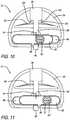
- FIG. 10is an elevational view of the variable amplitude assembly showing the movable member in the first position and the interference member in the deployed position;
- FIG. 11is an elevational view of the variable amplitude assembly showing the movable member in the second position and the interference member in the deployed position;
- FIG. 12is a side elevational view of the drive train in the second percussive therapy device and with the moveable member in the first position, thus providing a smaller amplitude
- FIG. 13is a side elevational view of the drive train in the second percussive therapy device and with the moveable member in the second position, thus providing a larger amplitude;
- FIG. 14is a perspective view of a variable amplitude assembly in accordance with a preferred embodiment of the present invention.
- FIG. 15is a perspective view of a variable amplitude assembly that includes an electromagnet in accordance with a preferred embodiment of the present invention.
- FIG. 16is an exploded perspective view of the variable amplitude assembly of FIG. 15 ;
- FIG. 17is an elevational view of the variable amplitude assembly showing the movable member in the first position and the interference member in the rest position;
- FIG. 18is an elevational view of the variable amplitude assembly showing the movable member in the second position and the interference member in the rest position;
- FIG. 19is an elevational view of the variable amplitude assembly showing the movable member in the first position and the interference member in the deployed position;
- FIG. 20is a side elevational view of the variable amplitude assembly showing the movable member in the second position and the interference member in the deployed position;
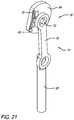
- FIG. 21is a perspective view of a drive train that includes a variable amplitude assembly in accordance with a preferred embodiment of the present invention.
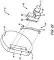
- FIG. 22is an exploded perspective view of the variable amplitude assembly
- FIG. 23is an elevational view of the variable amplitude assembly showing the movable member in the first position
- FIG. 24is an elevational view of the variable amplitude assembly showing the movable member in the second position.
- references in this specification to “one embodiment” or “an embodiment”means that a particular feature, structure, or characteristic described in connection with the embodiment is included in at least one embodiment of the disclosure. Appearances of the phrase “in one embodiment” in various places in the specification do not necessarily refer to the same embodiment, nor are separate or alternative embodiments mutually exclusive of other embodiments. Moreover, various features are described which may be exhibited by some embodiments and not by others. Similarly, various requirements are described which may be requirements for some embodiments but not other embodiments.
- FIGS. 1 and 2show different types of percussive massage devices 100 and 101 in which the variable amplitude assembly 12 can be used.
- the drive train assembly 10 shown in FIG. 3 and other figuresis the particular one that can be used in percussive massage device 101 .
- the drive train assembly 10generally includes the variable amplitude assembly 12 , motor 14 , motor shaft 16 , push rod 18 and reciprocating shaft 20 .
- the rotation of the motor shaft 16is converted to reciprocating motion of the reciprocating shaft 20 via a linkage assembly (or push rod assembly) 22 that includes the push rod 18 that is pivotably connected to the reciprocating shaft 20 (see pivot pin 24 ) and a counterweight or an eccentric weight member 54 that is part of the variable amplitude assembly 12 .
- An offset shaft 72is operatively connected (e.g., pivotably connected) to the push rod 18 . It will be appreciated that the axis of the offset shaft 72 is offset from the axis of rotation of the motor shaft 32 .
- the motor 14is mounted on a motor mount 26 .
- the variable amplitude assembly 12includes the eccentric weight member 54 and a shaft opening 56 therein that receives the rotating drive shaft of the motor, an interference member 85 , a movable member 58 and a spring 60 (preferably a spring) that is received in a spring channel 61 .
- the movable member 58includes a main body portion 59 , two slide members 86 that are received in slots 68 that are defined in the eccentric weight member 54 , the offset shaft 72 and a tooth 88 that interacts with a stop member 90 on the interference member 85 .
- the interference memberalso includes an opening 91 defined therein through which the spring 60 extends, and a weight 94 further described below.
- the interference member 85is received in and seated in a channel 96 defined in the eccentric weight member 54 .
- Fastenerse.g., threaded fasteners
- the ends of the spring 60are received in openings defined in the eccentric weight member that are positioned near the ends of the spring channel 61 .
- FIGS. 8-11show the different positions of the movable member 58 and the interference member 85 .
- the movable member 58is movable or slidable between a first position ( FIGS. 8 and 10 ) and a second position ( FIGS. 9 and 11 ).
- the interference member 85is movable or slidable between a rest position ( FIGS. 8 and 10 ) and a deployed position ( FIGS. 9 and 11 ).
- Spring 60biases the interference member 85 to the rest position. Shoulders 102 on the weight 94 contact stop surface 104 in the rest position (see FIG. 8 ).
- the movable member 58is located at the first position when the drive shaft of the motor is rotated in a first direction (clockwise or counterclockwise) and the movable member slides or translates to the second position when the drive shaft is reversed and begins to rotate in the opposite direction.
- the interference member 85remains in the rest position.
- the tooth 88 on the movable member 58is not in engagement with and is spaced from stop member 90 such that movable member 58 can move linearly along slots 68 ( FIGS. 8 and 10 ).
- the eccentric or centripetal forcecauses the movable member 58 to move to the other of the first or second position.
- the eccentric or centripetal force on the weightcauses the interference member 85 to overcome the spring force of the spring 60 and the interference member 85 moves outwardly within channel 96 , thereby causing the stop member 90 to move into the linear path of tooth 88 , thus blocking linear movement of the tooth 88 and the movable member 58 and locking or securing the movable member FIGS. 9 and 11 ) in either the first or second position (depending on the rotational direction of the eccentric weight member 54 ).
- Eccentric forcecauses the movable member 58 and the slide members 86 to move to the opposite end of the slots 68 when the motor is reversed.
- the movable member 58will be located at the first position, as shown in FIGS. 8 and 10 , when the eccentric weight member 54 is rotated counterclockwise (based on the configuration shown in FIGS. 8-11 ) and the movable member 58 will be located at the second position, as shown in FIGS. 9 and 11 , when the eccentric weight member 54 is rotated clockwise (based on the configuration shown in FIGS. 8-11 ).
- the opposite ends of slots 68are stop members that stop the movable member 58 as it moves when the motor direction is reversed.
- the direction of rotation of the motor drive shaftdetermines the amplitude of the reciprocating movement of the reciprocating shaft and, therefore, the massage attachment.
- FIGS. 8 and 9also show the axis of rotation A 1 of the eccentric weight member 54 and the axis of offset shaft 72 A 2 .
- the distance between A 1 and A 2is greater when the movable member 58 is in the second position than when the movable member 58 is in the first position.
- the reciprocating shaft 20and massage attachment 105 ) has a greater amplitude or stroke when the movable member 58 is in the second position than when the movable member 58 is in the first position.
- the amplitudeis 8 mm when the movable member is in the first position (A 1 is 4 mm from A 2 ) and 16 mm when the movable member is in the second position (A 1 is 8 mm from A 2 ).
- shaft 72 (and A 2 )are positioned closer to one end of movable member 58 than the other to provide the different distances between A 1 and A 2 when the movable member is in the first and second positions.
- the drive train 50can be used with any type of motor. The use of a brushless DC motor is not limiting on the invention.
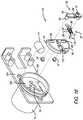
- FIGS. 12 and 13show the variable amplitude mechanism or assembly 12 in the drive train 10 of percussive massage device 101 .
- FIG. 12shows the variable amplitude assembly 12 with the movable member in the first position and
- FIG. 13shows the variable amplitude assembly 12 with the movable member in the second position.
- FIG. 14shows another preferred embodiment of a variable amplitude assembly 30 that is a variation of the variable amplitude assembly 12 shown in FIGS. 3-13 . Therefore, all text above related to the previous embodiment applies to this embodiment as well and all parts are interchangeable.
- variable amplitude assembly 30includes the eccentric weight member 54 , interference member 85 , movable member 58 and spring 60 (preferably a torsion spring) that is received on a pin 92 that is part of and/or extends from the interference member 85 .
- the movable member 58includes shaft 72 that receives and, in use, reciprocates push rod 62 and tooth 88 that interacts with stop member 90 on the interference member 85 .
- the interference memberalso includes a pin 92 that receives the coil portion of the spring 60 and a weight 94 further described below.
- the interference member 85is received in and seated in channel 96 defined in the eccentric weight member 54 . As shown in FIG.
- the ends of the torsion spring 60are received in and movable along a linear groove 103 defined in a side surface of the eccentric weight member 54 .
- the positioning of the spring 60is the biggest difference with the embodiment above. However, the spring 60 operates in the same manner as the spring in the embodiment shown FIGS. 3-13 .
- Spring 60biases the interference member 85 to the rest position. Shaft opening 56 , and slide members 86 are not shown in FIG. 14 , but are the same as shown in FIG. 7 .
- the positioning of the movable member 58 , offset shaft 72 , interference member 85 , axes A 1 and A 2 and related components shown in FIGS. 8-11apply to variable amplitude assembly 30 .
- variable amplitude assembly 30As the eccentric weight member 54 begins to rotate in the opposite direction from the previous use, the eccentric or centripetal force causes the movable member 58 to move to the other of the first or second position. As the eccentric weight member continues to rotate and speed up and reaches a desired RPM, the eccentric or centripetal force on the weight causes the interference member 85 to overcome the spring force of the spring 60 and the interference member 85 moves outwardly within channel 96 , thereby causing the stop member 90 to move into the linear path of tooth 88 , thus blocking linear movement of the tooth 88 and the movable member 58 and locking or securing the movable member FIGS. 9 and 11 ) in either the first or second position (depending on the rotational direction of the eccentric weight member 54 ).
- FIGS. 15-20show another embodiment of a variable amplitude assembly 110 for use with a drive train in a percussive massage device for varying the amplitude of the output shaft and the massage element or attachment.
- Variable amplitude assembly 110operates similarly to variable amplitude assemblies 12 and 30 above, but uses an electromagnet instead of the eccentric force to move the interference member 85 . Therefore, all text herein related to the other embodiments discussed applies to this embodiment as well and all parts are interchangeable.
- the variable amplitude assembly 110includes eccentric weight member 54 and a shaft opening (not shown) therein that receives the rotating drive shaft 16 of the motor 14 , an interference member 85 , a movable member 58 , and a spring 60 (preferably a coil spring).
- the movable member 58includes one or more slide members 86 that are received in slots 68 that are defined in the eccentric weight member 54 , an offset shaft 72 that receives and, in use, reciprocates the push rod and a tooth 88 that interacts with a stop member 90 on the interference member 85 .
- the interference member 85is received in and extends through a channel 96 defined in the eccentric weight member 54 .
- the spring 60is received on a shaft portion of interference member 85 and extends between a first end 112 of channel 96 and an extension member 114 on the interference member 85 .
- the interference member 85includes a head portion 116 .
- Threaded fastener(s) 97are receive in threaded openings in the slide member(s) 86 and secure the movable member 58 to the eccentric weight member 54 .
- the variable amplitude assembly 110includes an electromagnet 111 .
- the electromagnet 111is positioned outside a cylinder 124 on a mounting bracket 128 .
- the cylinder 124defines a rotation space 126 for the eccentric weight member 54 .
- the electromagnet 111is also positioned adjacent or close enough to head portion 116 of the interference member 85 that the electromagnet can pull the interference member radially outwardly and toward the electromagnet 111 when it is energized or turned on. Space is defined between the outer surface of the eccentric weight member 54 and the inner surface of the cylinder 124 .
- FIGS. 17-20show the different positions of the movable member 58 and the interference member 85 .
- the movable member 58is movable or slidable between a first position ( FIGS. 17 and 19 ) and a second position ( FIGS. 18 and 20 ).
- the interference member 85is movable or slidable between a rest position ( FIGS. 17 and 18 ) and a deployed position ( FIGS. 19 and 20 ).
- Spring 60biases the interference member 85 to the rest position.
- the extension member(s) 114contact stop surfaces 104 in the rest position (see FIG. 18 ).
- the movable member 58is located at the first position when the drive shaft of the motor is rotated in a first direction (clockwise or counterclockwise) and the movable member slides or translates to the second position when the drive shaft is reversed and begins to rotate in the opposite direction.
- the interference member 85remains in the rest position.
- the tooth 88 on the movable member 58engages with stop member 90 such that movable member 58 cannot move linearly along slots 68 ( FIGS. 17 and 18 ).
- the eccentric weight member 54begins to rotate in the opposite direction from the previous use and the electromagnet 111 is energized, thereby attracting the head portion 116 of the interference member 85 to the deployed position and pulling the stop member 90 away from the movable member and tooth 88 , such that stop member 90 is no longer in the linear path of tooth 88 (the tooth path between the first position and the second position) (see FIGS. 19 and 20 ).
- the eccentric or centripetal forcecauses the movable member 58 to move to the other of the first or second position (from the position in FIG. 25 to the position in FIG. 26 or vice versa).
- electromagnet 111is turned off or deenergized and the spring biases the interference member 85 back to the rest position, thereby causing the stop member 90 to move into the linear path of tooth 88 and locking or securing the movable member in either the first or second position (depending on the rotational direction of the eccentric weight member 54 ).
- Eccentric forcecauses the movable member 58 and the slide members 86 to move to the opposite end of the slots 68 when the motor is reversed (and the tooth 88 and stop member 90 are not engaged).
- the movable member 58will be located at the first position, as shown in FIGS. 17 and 19 , when the eccentric weight member 54 is rotated counterclockwise (based on the configuration shown in FIGS. 17-20 ) and the movable member 58 will be located at the second position, as shown in FIGS. 24 and 26 , when the eccentric weight member 54 is rotated clockwise (based on the configuration shown in FIGS. 17-20 ).
- the opposite ends of slots 68are stop members that stop the movable member 58 as it moves when the motor direction is reversed.
- the direction of rotation of the motor drive shaftdetermines the amplitude of the reciprocating movement of the reciprocating shaft and, therefore, the massage attachment.
- FIGS. 17 and 18also show the axis of rotation A 1 of the eccentric weight member 54 and the axis of shaft 72 A 2 .
- the distance between A 1 and A 2is greater when the movable member 58 is in the second position than when the movable member 58 is in the first position.
- the reciprocating shaft 20and massage attachment 105 ) have a greater amplitude or stroke when the movable member 58 is in the second position than when the movable member 58 is in the first position.
- the amplitudeis 8 mm when the movable member is in the first position (A 1 is 4 mm from A 2 ) and 16 mm when the movable member is in the second position (A 1 is 8 mm from A 2 ).
- shaft 72 (and A 2 )are positioned closer to one end of movable member 58 than the other to provide the different distances between A 1 and A 2 when the movable member is in the first and second positions.
- the drive traincan be used with any type of motor. The use of a brushless DC motor is not limiting on the invention.
- FIGS. 21-24show another embodiment of a variable amplitude assembly 52 for use with a drive train in a percussive massage device for varying the amplitude of the output shaft and the massage element or attachment.
- Variable amplitude assembly 52operates similarly to other variable amplitude assemblies discussed herein, but uses a leaf spring 60 . Therefore, all text herein related to the other embodiments discussed applies to this embodiment as well and all parts are interchangeable.
- variable amplitude assembly 52includes a eccentric weight member 54 , a movable member 58 , spring 60 and slot 68 .
- the movable member 58includes a slide portion 66 that is received in slot 68 that is defined in the eccentric weight member 54 , a pin 70 that extends outwardly and contacts spring 60 and an offset shaft 72 that receives and, in use, reciprocates the push rod 18 . It will be appreciated that the connections between the push rod 18 and the shaft 72 and the push rod 18 and the reciprocating shaft 20 are not shown in the drawings.
- the eccentric weight member 54includes recesses 74 defined therein that receive opposite ends of the spring 60 .
- the spring 60is a leaf spring and has a central portion that is spaced from the eccentric weight member 54 .
- the central portionincludes a first position portion 76 and a second position portion 78 that meet at an apex.
- the pin 70extends outwardly and contacts the first position portion 76 when the movable member 58 is in the first portion and the second position portion 78 when the movable member 58 is in the second portion.
- the spring 60is biased away from the eccentric weight member and against the pin 70 . As a result, the spring 60 helps hold the movable member 58 in the proper position and also helps prevent rattling and noise.
- the eccentric forceis enough to overcome the spring force of the spring 60 to allow the movable member 58 to move along slot 68 to the opposite end and for the pin 70 to travel over the apex of the spring 60 and to the other of the first or second position portion.
- the movable member 58includes a main body portion 80 , the pin 70 , the slide portion 66 and shaft 72 .
- the slide portion 66also includes channels 82 that engage or slide on the inner surfaces of the long sides of slot 68 .
- the movable member 58is positionable or movable within slot 68 between a first position ( FIG. 23 ) and a second position ( FIG. 24 ).
- the movable member 58is located at the first position when the drive shaft of the motor is rotated in a first direction (clockwise or counterclockwise) and the movable member slides or translates to the second position when the drive shaft is reversed and rotated in the opposite direction.
- Eccentric forcecauses the movable member 58 to move to the opposite end of the slot 68 when the motor is reversed. It will be appreciated that the movable member 58 will be located at the first position, as shown in FIG.
- FIGS. 23 and 24also show the axis of rotation A 1 of the eccentric weight member 54 and the axis of shaft 72 A 2 .
- the distance between A 1 and A 2is greater when the movable member 58 is in the second position than when the movable member 58 is in the first position.
- the reciprocating shaft 20has a greater amplitude or stroke when the movable member 58 is in the second position than when the movable member 58 is in the first position.
- the amplitudeis 8 mm when the movable member is in the first position (A 1 is 4 mm from A 2 ) and 16 mm when the movable member is in the second position (A 1 is 8 mm from A 2 ).
- slot 68is angled such that the first position end is closer to the axis of rotation A 1 than the second end.
- the user of the devicehas the ability to choose the amplitude by pushing a button or otherwise activating a switch.
- the button or switchcan be on the device or can be on a software application “app” executable on an electronic mobile device, such as a phone.
- the selection of the amplitudeis processed in the PCB and is translated into a motor shaft rotation direction (e.g., counterclockwise amplitude A, clockwise amplitude B).
- the motorthen begins rotating the shaft and the eccentric weight the appropriate direction, thereby causing the movable member to move to the position to result in the correct amplitude. 1 1 Is there more information that can be provided regarding how to activate the amplitude change?
- the words “comprise,” “comprising,” and the likeare to be construed in an inclusive sense, as opposed to an exclusive or exhaustive sense; that is to say, in the sense of “including, but not limited to.”
- the terms “connected,” “coupled,” or any variant thereofmeans any connection or coupling, either direct or indirect, between two or more elements; the coupling of connection between the elements can be physical, logical, or a combination thereof.
- the words “herein,” “above,” “below,” and words of similar importwhen used in this application, shall refer to this application as a whole and not to any particular portions of this application.
Landscapes
- Health & Medical Sciences (AREA)
- Epidemiology (AREA)
- Pain & Pain Management (AREA)
- Physical Education & Sports Medicine (AREA)
- Rehabilitation Therapy (AREA)
- Life Sciences & Earth Sciences (AREA)
- Animal Behavior & Ethology (AREA)
- General Health & Medical Sciences (AREA)
- Public Health (AREA)
- Veterinary Medicine (AREA)
- Orthopedic Medicine & Surgery (AREA)
- Rheumatology (AREA)
- Percussion Or Vibration Massage (AREA)
Abstract
Description
Claims (19)
Priority Applications (2)
| Application Number | Priority Date | Filing Date | Title |
|---|---|---|---|
| US17/018,044US11160721B2 (en) | 2015-06-20 | 2020-09-11 | Percussive therapy device with variable amplitude |
| US17/515,158US11957635B2 (en) | 2015-06-20 | 2021-10-29 | Percussive therapy device with variable amplitude |
Applications Claiming Priority (13)
| Application Number | Priority Date | Filing Date | Title |
|---|---|---|---|
| US201562182525P | 2015-06-20 | 2015-06-20 | |
| US15/186,859US20160367425A1 (en) | 2015-06-20 | 2016-06-20 | Apparatus, system, and method for a reciprocating treatment device |
| US15/458,920US20180263845A1 (en) | 2017-03-14 | 2017-03-14 | Apparatus, system, and method for a reciprocating treatment device |
| US15/920,322US10357425B2 (en) | 2015-06-20 | 2018-03-13 | Massage device and method of use |
| US201862785151P | 2018-12-26 | 2018-12-26 | |
| US16/357,984US10912707B2 (en) | 2015-06-20 | 2019-03-19 | Massage device and method of use |
| US201962844424P | 2019-05-07 | 2019-05-07 | |
| US201962899098P | 2019-09-11 | 2019-09-11 | |
| US16/675,772US10702448B2 (en) | 2017-03-14 | 2019-11-06 | Percussive massage device and method of use |
| US16/869,402US10857064B2 (en) | 2018-12-26 | 2020-05-07 | Percussive therapy device |
| US202063044860P | 2020-06-26 | 2020-06-26 | |
| US202063065114P | 2020-08-13 | 2020-08-13 | |
| US17/018,044US11160721B2 (en) | 2015-06-20 | 2020-09-11 | Percussive therapy device with variable amplitude |
Related Parent Applications (1)
| Application Number | Title | Priority Date | Filing Date |
|---|---|---|---|
| US16/869,402Continuation-In-PartUS10857064B2 (en) | 2015-06-20 | 2020-05-07 | Percussive therapy device |
Related Child Applications (1)
| Application Number | Title | Priority Date | Filing Date |
|---|---|---|---|
| US17/515,158ContinuationUS11957635B2 (en) | 2015-06-20 | 2021-10-29 | Percussive therapy device with variable amplitude |
Publications (2)
| Publication Number | Publication Date |
|---|---|
| US20200405574A1 US20200405574A1 (en) | 2020-12-31 |
| US11160721B2true US11160721B2 (en) | 2021-11-02 |
Family
ID=74042959
Family Applications (1)
| Application Number | Title | Priority Date | Filing Date |
|---|---|---|---|
| US17/018,044ActiveUS11160721B2 (en) | 2015-06-20 | 2020-09-11 | Percussive therapy device with variable amplitude |
Country Status (1)
| Country | Link |
|---|---|
| US (1) | US11160721B2 (en) |
Cited By (26)
| Publication number | Priority date | Publication date | Assignee | Title |
|---|---|---|---|---|
| US20220047453A1 (en)* | 2015-06-20 | 2022-02-17 | Therabody, Inc. | Percussive therapy device with variable amplitude |
| USD987844S1 (en) | 2021-08-31 | 2023-05-30 | MerchSource, LLC | Percussion massager |
| USD994898S1 (en) | 2021-11-17 | 2023-08-08 | MerchSource, LLC | Percussion massager |
| USD995812S1 (en) | 2021-11-22 | 2023-08-15 | MerchSource, LLC | Percussion massager |
| USD1004121S1 (en) | 2021-12-31 | 2023-11-07 | MerchSource, LLC | Pivoting percussion massager |
| USD1004119S1 (en) | 2021-08-31 | 2023-11-07 | MerchSource, LLC | Percussion massager |
| USD1004118S1 (en) | 2021-08-31 | 2023-11-07 | MerchSource, LLC | Percussion massager |
| USD1004117S1 (en) | 2021-08-31 | 2023-11-07 | MerchSource, LLC | Percussion massager |
| USD1004122S1 (en) | 2021-12-31 | 2023-11-07 | MerchSource, LLC | Pivoting percussion massager |
| USD1009292S1 (en) | 2021-12-22 | 2023-12-26 | MerchSource, LLC | Percussion massager |
| USD1018881S1 (en) | 2021-12-22 | 2024-03-19 | MerchSource, LLC | Percussion massager |
| USD1047207S1 (en)* | 2023-09-19 | 2024-10-15 | Therabody, Inc. | Attachment for massage device |
| USD1051414S1 (en) | 2021-08-31 | 2024-11-12 | MerchSource, LLC | Percussion massager |
| USD1052749S1 (en)* | 2023-08-24 | 2024-11-26 | Therabody, Inc. | Attachment for massage device |
| USD1053376S1 (en)* | 2023-09-01 | 2024-12-03 | Therabody, Inc. | Attachment for massage device |
| USD1053375S1 (en)* | 2023-08-01 | 2024-12-03 | Therabody, Inc. | Attachment for massage device |
| US12161599B1 (en) | 2023-09-21 | 2024-12-10 | Therabody, Inc. | Systems, methods, and devices for percussive massage therapy |
| US20250025369A1 (en)* | 2019-05-07 | 2025-01-23 | Therabody, Inc. | Chair including percussive massage therapy |
| USD1060711S1 (en) | 2021-08-31 | 2025-02-04 | MerchSource, LLC | Percussion massager |
| USD1078077S1 (en) | 2021-08-31 | 2025-06-03 | MerchSource, LLC | Percussion massager |
| USD1079043S1 (en) | 2021-08-31 | 2025-06-10 | MerchSource, LLC | Percussion massager |
| USD1079044S1 (en) | 2021-08-31 | 2025-06-10 | MerchSource, LLC | Percussion massager |
| USD1079041S1 (en) | 2021-08-31 | 2025-06-10 | MerchSource, LLC | Percussion massager |
| USD1079042S1 (en) | 2021-08-31 | 2025-06-10 | MerchSource, LLC | Percussion massager |
| US12329711B2 (en) | 2018-12-26 | 2025-06-17 | Therabody, Inc. | Percussive therapy device with interchangeable modules |
| US12402686B2 (en) | 2023-06-14 | 2025-09-02 | Therabody, Inc. | Articles of footwear having therapeutic assemblies |
Families Citing this family (59)
| Publication number | Priority date | Publication date | Assignee | Title |
|---|---|---|---|---|
| US9889066B2 (en) | 2013-07-01 | 2018-02-13 | Good Fortune 5, Llc | Massaging device having a heat sink |
| USD877351S1 (en)* | 2017-10-02 | 2020-03-03 | Theragun, Inc. | Therapeutic device |
| USD879986S1 (en)* | 2018-12-26 | 2020-03-31 | Theragun, Inc. | Percussive massage device |
| US11730668B2 (en) | 2020-06-29 | 2023-08-22 | Therabody, Inc. | Vibrating therapy system and device |
| USD879985S1 (en)* | 2018-12-26 | 2020-03-31 | Theragun, Inc. | Percussive massage device |
| USD884915S1 (en)* | 2018-12-26 | 2020-05-19 | Theragun, Inc. | Percussive massage device |
| USD890942S1 (en)* | 2019-01-16 | 2020-07-21 | Theragun, Inc. | Massage element |
| USD890943S1 (en)* | 2019-01-17 | 2020-07-21 | Theragun, Inc. | Massage element |
| USD933845S1 (en)* | 2019-04-12 | 2021-10-19 | Zhejiang Ruicheng Mechanical Power Co., Ltd | Fascia gun |
| USD934440S1 (en)* | 2019-05-29 | 2021-10-26 | Zhejiang Ruicheng Mechanical Power Co., Ltd. | Fascia gun |
| USD950088S1 (en)* | 2019-07-12 | 2022-04-26 | Achedaway (Shenzhen) Technology Co., Ltd. | Percussive massage gun |
| USD956989S1 (en)* | 2019-09-30 | 2022-07-05 | Shenzhen Breo Technology Co., Ltd. | Massager |
| USD952884S1 (en)* | 2019-09-30 | 2022-05-24 | Xiamen Simo Electronic Co., Ltd | Massage gun |
| USD949389S1 (en)* | 2019-11-15 | 2022-04-19 | Jiejia Ying | Deep tissue massager |
| USD949383S1 (en)* | 2019-12-04 | 2022-04-19 | Yong Kang Aijiu Industrial & Trade Co., Ltd | Deep tissue massager |
| USD949385S1 (en)* | 2019-12-26 | 2022-04-19 | Zhejiang Aerlang Technology Co., Ltd. | Massage gun |
| USD949381S1 (en)* | 2020-01-09 | 2022-04-19 | GoPlus Corp. | Massage device |
| JP1671113S (en)* | 2020-01-10 | 2020-10-26 | ||
| USD949384S1 (en)* | 2020-01-15 | 2022-04-19 | Shenzhen Create Future International Trading Company | Hand-held massager |
| USD963185S1 (en)* | 2020-02-14 | 2022-09-06 | Suzhou Wintech Tools Manufacturing Co., Ltd. | Massager |
| USD950089S1 (en)* | 2020-03-05 | 2022-04-26 | Body back company | Handle for a massage device |
| USD956249S1 (en)* | 2020-03-06 | 2022-06-28 | Min Ying | Percussion massage gun |
| USD949411S1 (en)* | 2020-03-30 | 2022-04-19 | YONGKANG CAS ACEME MEDICAL TECHNOLOGY Co., Ltd | Massage gun |
| USD949412S1 (en)* | 2020-04-13 | 2022-04-19 | YONGKANG CAS ACEME MEDICAL TECHNOLOGY Co., Ltd | Massage gun |
| USD959008S1 (en)* | 2020-06-15 | 2022-07-26 | Qinji Electronic Technology (Suzhou) Co., Ltd. | Massager |
| USD961796S1 (en)* | 2020-06-15 | 2022-08-23 | Qinji Electronic Technology (Suzhou) Co., Ltd. | Massager |
| USD958387S1 (en)* | 2020-06-15 | 2022-07-19 | Qinji Electronic Technology (Suzhou) Co., Ltd. | Massager |
| USD949400S1 (en)* | 2020-06-23 | 2022-04-19 | Flexir Recovery, Llc | Vibration therapy device |
| USD949401S1 (en)* | 2020-06-30 | 2022-04-19 | Golovan Ltd. | Handheld therapeutic device |
| USD953556S1 (en)* | 2020-07-31 | 2022-05-31 | Hyper Ice, Inc. | Percussive massage device |
| USD953557S1 (en)* | 2020-08-10 | 2022-05-31 | Shenzhen Goodrone Intelligent Technology Co., Ltd. | Percussive massage device |
| US10993874B1 (en)* | 2020-11-05 | 2021-05-04 | Hyper Ice, Inc. | Motor and piston assembly for percussive massage device |
| USD949419S1 (en)* | 2020-11-09 | 2022-04-19 | Fuan Yunshan Electronics Co., Ltd. | Massager |
| USD949368S1 (en)* | 2020-11-10 | 2022-04-19 | Xinlu Jin | Double heads massage gun |
| US11253423B1 (en)* | 2020-12-02 | 2022-02-22 | PlayMakar Inc. | Variable stroke percussive massage device |
| US11752064B2 (en) | 2020-12-02 | 2023-09-12 | PlayMakar, Inc. | Constrained and repositionable percussive massage device tool and tool receiver |
| CN214632946U (en)* | 2020-12-16 | 2021-11-09 | 东莞市谦禾电子科技有限公司 | Massager and massage mechanism thereof |
| USD949421S1 (en)* | 2020-12-23 | 2022-04-19 | Rechar Inc | Massage device |
| USD934442S1 (en)* | 2020-12-23 | 2021-10-26 | Yong Kang Aijiu Industrial & Trade Co., Ltd | Massage gun |
| USD963881S1 (en)* | 2020-12-29 | 2022-09-13 | Ping Deng | Massage appliance |
| USD1004793S1 (en) | 2021-03-02 | 2023-11-14 | Therabody, Inc. | Facial treatment device |
| US12343302B2 (en) | 2021-08-13 | 2025-07-01 | Hyperice Ip Subco, Llc | Combination applicator and adapter for percussive massage device |
| USD1018885S1 (en) | 2021-10-22 | 2024-03-19 | PlayMakar, Inc. | Dual head percussive massager tool with dome tips |
| USD1018887S1 (en) | 2021-10-22 | 2024-03-19 | PlayMakar, Inc. | Dual head percussive massager tool base |
| USD1018886S1 (en) | 2021-10-22 | 2024-03-19 | PlayMakar, Inc. | Dual head percussive massager tool with round tips |
| USD987845S1 (en) | 2021-10-28 | 2023-05-30 | Play Makar Inc. | Massage gun attachment head |
| USD987846S1 (en) | 2021-10-28 | 2023-05-30 | PlayMakar Inc. | Massager gun attachment shaft |
| USD980805S1 (en) | 2021-11-02 | 2023-03-14 | PlayMakar, Inc. | Massager control display |
| USD1000626S1 (en) | 2021-11-02 | 2023-10-03 | PlayMakar, Inc. | Percussive massage gun |
| USD998815S1 (en) | 2021-12-01 | 2023-09-12 | PlayMakar, Inc. | Massage gun head seal |
| USD988531S1 (en) | 2022-01-12 | 2023-06-06 | PlayMakar Inc. | Massage gun acupressure tip |
| USD1006242S1 (en) | 2022-01-20 | 2023-11-28 | PlayMakar, Inc. | Percussive massager device connecting rod |
| US11672728B1 (en) | 2022-04-05 | 2023-06-13 | PlayMakar Inc. | Selectable, configurable and interchangeable massage tool head system for percussion massage devices |
| USD975869S1 (en)* | 2022-04-11 | 2023-01-17 | Therabody, Inc. | Massage device |
| US11850204B2 (en) | 2022-05-09 | 2023-12-26 | PlayMakar, Inc. | System and method for locking percussion settings on a massage device |
| JP1746874S (en)* | 2022-06-06 | 2023-06-20 | fascial cancer | |
| US20240033173A1 (en)* | 2022-07-27 | 2024-02-01 | Nice Recovery Systems LLC | Real time adjustable amplitude and adjustable frequency percussive therapy device |
| USD1037472S1 (en)* | 2022-11-09 | 2024-07-30 | Chris Marshall | Massage gun |
| USD1027211S1 (en)* | 2023-09-27 | 2024-05-14 | Therabody, Inc. | Massage device |
Citations (65)
| Publication number | Priority date | Publication date | Assignee | Title |
|---|---|---|---|---|
| US3172675A (en) | 1963-02-19 | 1965-03-09 | Victor E Gonzalez | Ball socket attachment for impact tool |
| US3545301A (en) | 1969-06-02 | 1970-12-08 | Cincinnati Milacron Inc | Stepping motor damper |
| US3626934A (en) | 1970-04-06 | 1971-12-14 | Ernest R Andis | Massaging device |
| US3942251A (en) | 1971-09-17 | 1976-03-09 | Rockwell International Corporation | Saber saw |
| US4031763A (en)* | 1975-09-15 | 1977-06-28 | The Singer Company | Adjustable stroke length, reciprocating tools |
| US4150668A (en) | 1976-06-08 | 1979-04-24 | Johnston Lyman C | Massage device |
| US4173217A (en) | 1976-07-08 | 1979-11-06 | Johnston Lyman C | Massage apparatus |
| US4549535A (en) | 1982-12-06 | 1985-10-29 | Wing Thomas W | Linear motor massage apparatus |
| US4566442A (en) | 1982-04-28 | 1986-01-28 | Bio Mobuchi Co. Ltd. | Massager |
| US4730605A (en) | 1985-12-31 | 1988-03-15 | Wellness Innovations Corp. | Percussing body massager having amplitude adjustment means |
| DE3633888A1 (en)* | 1986-10-04 | 1988-04-07 | Licentia Gmbh | Jigsaw with a stroke movement of the plunger produced by a Scotch-yoke mechanism |
| JPH0219157A (en) | 1988-07-06 | 1990-01-23 | Sanden Eng Kk | Effective spot hitter |
| US5085207A (en) | 1991-01-28 | 1992-02-04 | Fiore Russell D | Device for deep massage and method of using |
| US5212887A (en) | 1992-03-18 | 1993-05-25 | S-B Power Tool Company | Counterbalanced orbital drive mechanism for saws and the like |
| JPH0751393A (en) | 1993-08-12 | 1995-02-28 | Hitachi Metals Ltd | Electric massage machine |
| US5417644A (en) | 1993-12-02 | 1995-05-23 | Lee; Ming L. | Reciprocating massage apparatus |
| US5569168A (en) | 1994-01-14 | 1996-10-29 | Wahl Clipper Corporation | Kneader massager having dwell feature |
| US5573500A (en) | 1994-03-24 | 1996-11-12 | Biopit Co., Ltd. | Sole massage device |
| US5951501A (en) | 1996-12-20 | 1999-09-14 | Point Financial Associates | Pulsating muscle massaging device |
| US6228042B1 (en) | 1998-09-24 | 2001-05-08 | Thomas E. Dungan | Chiropractic adjusting tool |
| JP3077837U (en) | 2000-11-21 | 2001-06-08 | 利幸 古沼 | Electric shock treatment machine |
| US20010016697A1 (en) | 1998-04-09 | 2001-08-23 | Michael Gorsen | Methods and apparatus for stimulating gingiva |
| US20030009116A1 (en) | 2001-07-03 | 2003-01-09 | Luettgen Harold A. | Vibrating personal massager |
| US20030094356A1 (en) | 2001-11-20 | 2003-05-22 | Michael Waldron | Switch mechanism for a power tool |
| US20030144615A1 (en) | 2002-01-28 | 2003-07-31 | Chun-Kuang Lin | Rotating and vibrating massage shower nozzle |
| US20030195443A1 (en) | 2002-04-12 | 2003-10-16 | Miller Edward W. | Percussive therapeutic device |
| US6663657B1 (en) | 2002-11-27 | 2003-12-16 | Edward W. Miller | Percussive therapeutic device |
| US6682496B1 (en) | 1999-12-28 | 2004-01-27 | Jake W. Pivaroff | Deep muscle stimulator device |
| US20050109137A1 (en)* | 2003-11-20 | 2005-05-26 | Markus Hartmann | Movement conversion device for a hand-held power tool |
| JP2005204777A (en) | 2004-01-21 | 2005-08-04 | Omron Healthcare Co Ltd | Massage device |
| US20060025710A1 (en) | 2004-07-09 | 2006-02-02 | Manfred Schulz | Instrument for applying vibrations to the human body |
| US20060123941A1 (en) | 2001-12-13 | 2006-06-15 | Brian Wadge | Mechanism for use in a power tool and a power tool including such a mechanism |
| US20060192527A1 (en) | 2003-09-29 | 2006-08-31 | Sven Kageler | Battery-driven screwdriver |
| US20070144310A1 (en) | 2005-11-04 | 2007-06-28 | Credo Technology Corporation | Articulating drill with integrated circuit board and method of operation |
| US20070150004A1 (en) | 2004-08-26 | 2007-06-28 | Colloca Christopher J | Electromechanical Adjusting Instrument |
| US20070270727A1 (en) | 2005-12-21 | 2007-11-22 | David Khorassani Zadeh | Apparatus, systems, and methods for continuous pressure technique therapy |
| US20080103419A1 (en) | 2006-10-25 | 2008-05-01 | Adamson Christopher D | Liposculpting Device |
| US20080169715A1 (en)* | 2007-01-17 | 2008-07-17 | Brookstone Purchasing, Inc. | Vibration apparatus and motor assembly therefore |
| US20080200849A1 (en) | 2007-02-05 | 2008-08-21 | Geoffrey Hollington | Body Massager with Learning Capability |
| WO2009014727A1 (en) | 2007-07-24 | 2009-01-29 | Activator Methods International, Limited | Portable chiropractic adjustor |
| US7927259B1 (en) | 2008-08-26 | 2011-04-19 | Rix Paul B | Body impact trainer system |
| US7996996B2 (en) | 2003-08-01 | 2011-08-16 | Makita Corporation | Reciprocating power tool |
| KR101123926B1 (en) | 2011-08-24 | 2012-04-13 | 주식회사 에이티시스템 | Vibration massage apparatus for muscle |
| US20120253245A1 (en) | 2010-12-16 | 2012-10-04 | Stanbridge Stanley R | Therapeutic device and method for scar tissue therapy having intermediate and opposed heads |
| US8342187B2 (en) | 2008-03-06 | 2013-01-01 | Conopco, Inc. | Vibrating device |
| US20130133210A1 (en) | 2011-11-30 | 2013-05-30 | Robert Bosch Gmbh | Articulating Jig Saw |
| US20130138023A1 (en) | 2010-03-22 | 2013-05-30 | Atlantotec | Device for massaging or treating the muscles of the back and neck |
| US20130261516A1 (en) | 2012-03-30 | 2013-10-03 | Joseph J. Cilea | Hand Held Percussion Device |
| US20130281897A1 (en)* | 2003-09-04 | 2013-10-24 | Ahof Biophysical Systems Inc. | Non-invasive reperfusion system by deformation of remote, superficial arteries at a frequency much greater than the pulse rate |
| US20140180331A1 (en) | 2011-08-09 | 2014-06-26 | Thomas W. Turner | Neuromuscular therapy device and method |
| US20140190023A1 (en)* | 2011-08-31 | 2014-07-10 | Infusion Brands International, Inc. | Dual Reciprocating Apparatus and Saw Blades for Use Therewith |
| WO2014118596A1 (en) | 2013-02-01 | 2014-08-07 | Telefield Limited | Facial care apparatus and attachments |
| US20150005682A1 (en)* | 2013-07-01 | 2015-01-01 | Good Fortune 5, Llc | Massaging device |
| US8951216B2 (en) | 2008-06-30 | 2015-02-10 | Amorepacific Corporation | Skin massager |
| WO2015038005A2 (en) | 2013-09-11 | 2015-03-19 | Nevroflex AS | A stimulation and treatment device |
| US20150119771A1 (en) | 2013-10-28 | 2015-04-30 | PSOAS Massage Therapy Offices, P.C. | Device and method for trigger point massage therapy |
| US20150148592A1 (en) | 2013-11-22 | 2015-05-28 | Maurice S. Kanbar Revocable Trust | Personal massager |
| US20150375315A1 (en) | 2013-02-01 | 2015-12-31 | Makita Corporation | Cutting tool |
| US20160112841A1 (en) | 1999-07-29 | 2016-04-21 | Bryan Holland | Locator system |
| US20170156974A1 (en) | 2015-12-08 | 2017-06-08 | Healthy Muscles Llc | Device for delivery of resonant frequencies to treated muscles |
| US20180200141A1 (en) | 2015-06-20 | 2018-07-19 | Theragun, LLC | Massage device and method of use |
| US20180236572A1 (en) | 2017-02-23 | 2018-08-23 | Makita Corporation | Reciprocating saw |
| US20180243158A1 (en) | 2015-09-16 | 2018-08-30 | Indiana University Research And Technology Corporation | Quantification of force during soft tissue massage for research and clinical use |
| US20180279843A1 (en) | 2017-03-31 | 2018-10-04 | L'oreal | Communication and power interface for a cosmetic device |
| US10314762B1 (en) | 2018-11-12 | 2019-06-11 | Hyper Ice, Inc. | Battery-powered percussive massage device with pressure sensor |
- 2020
- 2020-09-11USUS17/018,044patent/US11160721B2/enactiveActive
Patent Citations (67)
| Publication number | Priority date | Publication date | Assignee | Title |
|---|---|---|---|---|
| US3172675A (en) | 1963-02-19 | 1965-03-09 | Victor E Gonzalez | Ball socket attachment for impact tool |
| US3545301A (en) | 1969-06-02 | 1970-12-08 | Cincinnati Milacron Inc | Stepping motor damper |
| US3626934A (en) | 1970-04-06 | 1971-12-14 | Ernest R Andis | Massaging device |
| US3942251A (en) | 1971-09-17 | 1976-03-09 | Rockwell International Corporation | Saber saw |
| US4031763A (en)* | 1975-09-15 | 1977-06-28 | The Singer Company | Adjustable stroke length, reciprocating tools |
| US4150668A (en) | 1976-06-08 | 1979-04-24 | Johnston Lyman C | Massage device |
| US4173217A (en) | 1976-07-08 | 1979-11-06 | Johnston Lyman C | Massage apparatus |
| US4566442A (en) | 1982-04-28 | 1986-01-28 | Bio Mobuchi Co. Ltd. | Massager |
| US4549535A (en) | 1982-12-06 | 1985-10-29 | Wing Thomas W | Linear motor massage apparatus |
| US4730605A (en) | 1985-12-31 | 1988-03-15 | Wellness Innovations Corp. | Percussing body massager having amplitude adjustment means |
| DE3633888A1 (en)* | 1986-10-04 | 1988-04-07 | Licentia Gmbh | Jigsaw with a stroke movement of the plunger produced by a Scotch-yoke mechanism |
| JPH0219157A (en) | 1988-07-06 | 1990-01-23 | Sanden Eng Kk | Effective spot hitter |
| US5085207A (en) | 1991-01-28 | 1992-02-04 | Fiore Russell D | Device for deep massage and method of using |
| US5212887A (en) | 1992-03-18 | 1993-05-25 | S-B Power Tool Company | Counterbalanced orbital drive mechanism for saws and the like |
| JPH0751393A (en) | 1993-08-12 | 1995-02-28 | Hitachi Metals Ltd | Electric massage machine |
| US5417644A (en) | 1993-12-02 | 1995-05-23 | Lee; Ming L. | Reciprocating massage apparatus |
| US5569168A (en) | 1994-01-14 | 1996-10-29 | Wahl Clipper Corporation | Kneader massager having dwell feature |
| US5573500A (en) | 1994-03-24 | 1996-11-12 | Biopit Co., Ltd. | Sole massage device |
| US5951501A (en) | 1996-12-20 | 1999-09-14 | Point Financial Associates | Pulsating muscle massaging device |
| US20010016697A1 (en) | 1998-04-09 | 2001-08-23 | Michael Gorsen | Methods and apparatus for stimulating gingiva |
| US6228042B1 (en) | 1998-09-24 | 2001-05-08 | Thomas E. Dungan | Chiropractic adjusting tool |
| US20160112841A1 (en) | 1999-07-29 | 2016-04-21 | Bryan Holland | Locator system |
| US6682496B1 (en) | 1999-12-28 | 2004-01-27 | Jake W. Pivaroff | Deep muscle stimulator device |
| JP3077837U (en) | 2000-11-21 | 2001-06-08 | 利幸 古沼 | Electric shock treatment machine |
| US20030009116A1 (en) | 2001-07-03 | 2003-01-09 | Luettgen Harold A. | Vibrating personal massager |
| US20030094356A1 (en) | 2001-11-20 | 2003-05-22 | Michael Waldron | Switch mechanism for a power tool |
| US20060123941A1 (en) | 2001-12-13 | 2006-06-15 | Brian Wadge | Mechanism for use in a power tool and a power tool including such a mechanism |
| US20030144615A1 (en) | 2002-01-28 | 2003-07-31 | Chun-Kuang Lin | Rotating and vibrating massage shower nozzle |
| US20030195443A1 (en) | 2002-04-12 | 2003-10-16 | Miller Edward W. | Percussive therapeutic device |
| US6663657B1 (en) | 2002-11-27 | 2003-12-16 | Edward W. Miller | Percussive therapeutic device |
| US7996996B2 (en) | 2003-08-01 | 2011-08-16 | Makita Corporation | Reciprocating power tool |
| US20130281897A1 (en)* | 2003-09-04 | 2013-10-24 | Ahof Biophysical Systems Inc. | Non-invasive reperfusion system by deformation of remote, superficial arteries at a frequency much greater than the pulse rate |
| US20060192527A1 (en) | 2003-09-29 | 2006-08-31 | Sven Kageler | Battery-driven screwdriver |
| US20050109137A1 (en)* | 2003-11-20 | 2005-05-26 | Markus Hartmann | Movement conversion device for a hand-held power tool |
| JP2005204777A (en) | 2004-01-21 | 2005-08-04 | Omron Healthcare Co Ltd | Massage device |
| US20060025710A1 (en) | 2004-07-09 | 2006-02-02 | Manfred Schulz | Instrument for applying vibrations to the human body |
| US20070150004A1 (en) | 2004-08-26 | 2007-06-28 | Colloca Christopher J | Electromechanical Adjusting Instrument |
| US20070144310A1 (en) | 2005-11-04 | 2007-06-28 | Credo Technology Corporation | Articulating drill with integrated circuit board and method of operation |
| US20070270727A1 (en) | 2005-12-21 | 2007-11-22 | David Khorassani Zadeh | Apparatus, systems, and methods for continuous pressure technique therapy |
| US20080103419A1 (en) | 2006-10-25 | 2008-05-01 | Adamson Christopher D | Liposculpting Device |
| US20080169715A1 (en)* | 2007-01-17 | 2008-07-17 | Brookstone Purchasing, Inc. | Vibration apparatus and motor assembly therefore |
| US20080200849A1 (en) | 2007-02-05 | 2008-08-21 | Geoffrey Hollington | Body Massager with Learning Capability |
| JP2010534110A (en) | 2007-07-24 | 2010-11-04 | アクティヴェイター メソッズ インターナショナル リミテッド | Portable acupressure corrector |
| WO2009014727A1 (en) | 2007-07-24 | 2009-01-29 | Activator Methods International, Limited | Portable chiropractic adjustor |
| US8342187B2 (en) | 2008-03-06 | 2013-01-01 | Conopco, Inc. | Vibrating device |
| US8951216B2 (en) | 2008-06-30 | 2015-02-10 | Amorepacific Corporation | Skin massager |
| US7927259B1 (en) | 2008-08-26 | 2011-04-19 | Rix Paul B | Body impact trainer system |
| US20130138023A1 (en) | 2010-03-22 | 2013-05-30 | Atlantotec | Device for massaging or treating the muscles of the back and neck |
| US20120253245A1 (en) | 2010-12-16 | 2012-10-04 | Stanbridge Stanley R | Therapeutic device and method for scar tissue therapy having intermediate and opposed heads |
| US20140180331A1 (en) | 2011-08-09 | 2014-06-26 | Thomas W. Turner | Neuromuscular therapy device and method |
| KR101123926B1 (en) | 2011-08-24 | 2012-04-13 | 주식회사 에이티시스템 | Vibration massage apparatus for muscle |
| US20140190023A1 (en)* | 2011-08-31 | 2014-07-10 | Infusion Brands International, Inc. | Dual Reciprocating Apparatus and Saw Blades for Use Therewith |
| US20130133210A1 (en) | 2011-11-30 | 2013-05-30 | Robert Bosch Gmbh | Articulating Jig Saw |
| US20130261516A1 (en) | 2012-03-30 | 2013-10-03 | Joseph J. Cilea | Hand Held Percussion Device |
| WO2014118596A1 (en) | 2013-02-01 | 2014-08-07 | Telefield Limited | Facial care apparatus and attachments |
| US20150375315A1 (en) | 2013-02-01 | 2015-12-31 | Makita Corporation | Cutting tool |
| US20150005682A1 (en)* | 2013-07-01 | 2015-01-01 | Good Fortune 5, Llc | Massaging device |
| US20180296433A1 (en) | 2013-07-01 | 2018-10-18 | Hyper Ice, Inc. | Massaging device |
| WO2015038005A2 (en) | 2013-09-11 | 2015-03-19 | Nevroflex AS | A stimulation and treatment device |
| US20150119771A1 (en) | 2013-10-28 | 2015-04-30 | PSOAS Massage Therapy Offices, P.C. | Device and method for trigger point massage therapy |
| US20150148592A1 (en) | 2013-11-22 | 2015-05-28 | Maurice S. Kanbar Revocable Trust | Personal massager |
| US20180200141A1 (en) | 2015-06-20 | 2018-07-19 | Theragun, LLC | Massage device and method of use |
| US20180243158A1 (en) | 2015-09-16 | 2018-08-30 | Indiana University Research And Technology Corporation | Quantification of force during soft tissue massage for research and clinical use |
| US20170156974A1 (en) | 2015-12-08 | 2017-06-08 | Healthy Muscles Llc | Device for delivery of resonant frequencies to treated muscles |
| US20180236572A1 (en) | 2017-02-23 | 2018-08-23 | Makita Corporation | Reciprocating saw |
| US20180279843A1 (en) | 2017-03-31 | 2018-10-04 | L'oreal | Communication and power interface for a cosmetic device |
| US10314762B1 (en) | 2018-11-12 | 2019-06-11 | Hyper Ice, Inc. | Battery-powered percussive massage device with pressure sensor |
Non-Patent Citations (10)
| Title |
|---|
| AU 2016284030 Examination Report dated May 7, 2018. |
| CA 2990178 Office Action dated Oct. 25, 2018. |
| JP2018-517683 Office Action dated Oct. 25, 2018. |
| PCT/US2016/038326 International Search Report & Written Opinion dated Sep. 1, 2016. |
| PCT/US2018/022426 International Search Report & Written Opinion dated May 31, 2018. |
| PCT/US2020/031936 International Search Report & Written Opinion dated Sep. 11, 2020. |
| PCT/US2020/50399 International Search Report & Written Opinion dated Feb. 4, 2021. |
| Rachel [no family name indicated], "Jigsaw Massager", Apr. 18, 2010 (https://web.archive.org/web/20100418041422/http://www.instructables.com/id/Jigsaw-Massager/). |
| Rockwell Trans4mer Operating Manual for Multi-purpose saw, Model RK2516/RK2516K, 2011. |
| WORX Trans4mer "Safety and Operating Manual Original Instructions" for 12V Li-Ion Multi-purpose saw, WX540, WX540.3, WX540.9, 2013. |
Cited By (38)
| Publication number | Priority date | Publication date | Assignee | Title |
|---|---|---|---|---|
| US11957635B2 (en)* | 2015-06-20 | 2024-04-16 | Therabody, Inc. | Percussive therapy device with variable amplitude |
| US20220047453A1 (en)* | 2015-06-20 | 2022-02-17 | Therabody, Inc. | Percussive therapy device with variable amplitude |
| US12329711B2 (en) | 2018-12-26 | 2025-06-17 | Therabody, Inc. | Percussive therapy device with interchangeable modules |
| US20250025369A1 (en)* | 2019-05-07 | 2025-01-23 | Therabody, Inc. | Chair including percussive massage therapy |
| USD1018888S1 (en) | 2021-08-31 | 2024-03-19 | MerchSource, LLC | Percussion massager |
| USD1078077S1 (en) | 2021-08-31 | 2025-06-03 | MerchSource, LLC | Percussion massager |
| USD1004119S1 (en) | 2021-08-31 | 2023-11-07 | MerchSource, LLC | Percussion massager |
| USD1004118S1 (en) | 2021-08-31 | 2023-11-07 | MerchSource, LLC | Percussion massager |
| USD1004117S1 (en) | 2021-08-31 | 2023-11-07 | MerchSource, LLC | Percussion massager |
| USD1079042S1 (en) | 2021-08-31 | 2025-06-10 | MerchSource, LLC | Percussion massager |
| USD1009294S1 (en) | 2021-08-31 | 2023-12-26 | MerchSource, LLC | Percussion massager |
| USD1060701S1 (en) | 2021-08-31 | 2025-02-04 | MerchSource, LLC | Percussion massager |
| USD1060711S1 (en) | 2021-08-31 | 2025-02-04 | MerchSource, LLC | Percussion massager |
| USD1060700S1 (en) | 2021-08-31 | 2025-02-04 | MerchSource, LLC | Percussion massager |
| USD987844S1 (en) | 2021-08-31 | 2023-05-30 | MerchSource, LLC | Percussion massager |
| USD1004123S1 (en) | 2021-08-31 | 2023-11-07 | MerchSource, LLC | Percussion massager |
| USD1051414S1 (en) | 2021-08-31 | 2024-11-12 | MerchSource, LLC | Percussion massager |
| USD1079041S1 (en) | 2021-08-31 | 2025-06-10 | MerchSource, LLC | Percussion massager |
| USD1079044S1 (en) | 2021-08-31 | 2025-06-10 | MerchSource, LLC | Percussion massager |
| USD1079043S1 (en) | 2021-08-31 | 2025-06-10 | MerchSource, LLC | Percussion massager |
| USD994898S1 (en) | 2021-11-17 | 2023-08-08 | MerchSource, LLC | Percussion massager |
| USD995812S1 (en) | 2021-11-22 | 2023-08-15 | MerchSource, LLC | Percussion massager |
| USD1079038S1 (en) | 2021-12-22 | 2025-06-10 | MerchSource, LLC | Percussion massager |
| USD1018881S1 (en) | 2021-12-22 | 2024-03-19 | MerchSource, LLC | Percussion massager |
| USD1060705S1 (en) | 2021-12-22 | 2025-02-04 | MerchSource, LLC | Percussion massager |
| USD1009292S1 (en) | 2021-12-22 | 2023-12-26 | MerchSource, LLC | Percussion massager |
| USD1060707S1 (en) | 2021-12-31 | 2025-02-04 | MerchSource, LLC | Pivoting percussion massager |
| USD1060706S1 (en) | 2021-12-31 | 2025-02-04 | MerchSource, LLC | Pivoting percussion massager |
| USD1004122S1 (en) | 2021-12-31 | 2023-11-07 | MerchSource, LLC | Pivoting percussion massager |
| USD1004121S1 (en) | 2021-12-31 | 2023-11-07 | MerchSource, LLC | Pivoting percussion massager |
| US12402686B2 (en) | 2023-06-14 | 2025-09-02 | Therabody, Inc. | Articles of footwear having therapeutic assemblies |
| USD1053375S1 (en)* | 2023-08-01 | 2024-12-03 | Therabody, Inc. | Attachment for massage device |
| USD1052749S1 (en)* | 2023-08-24 | 2024-11-26 | Therabody, Inc. | Attachment for massage device |
| USD1053376S1 (en)* | 2023-09-01 | 2024-12-03 | Therabody, Inc. | Attachment for massage device |
| USD1047207S1 (en)* | 2023-09-19 | 2024-10-15 | Therabody, Inc. | Attachment for massage device |
| US12285379B2 (en) | 2023-09-21 | 2025-04-29 | Therabody, Inc. | Systems, methods, and devices for percussive massage therapy |
| US12290486B2 (en) | 2023-09-21 | 2025-05-06 | Therabody, Inc. | Systems, methods, and devices for percussive massage therapy |
| US12161599B1 (en) | 2023-09-21 | 2024-12-10 | Therabody, Inc. | Systems, methods, and devices for percussive massage therapy |
Also Published As
| Publication number | Publication date |
|---|---|
| US20200405574A1 (en) | 2020-12-31 |
Similar Documents
| Publication | Publication Date | Title |
|---|---|---|
| US11160721B2 (en) | Percussive therapy device with variable amplitude | |
| US11957635B2 (en) | Percussive therapy device with variable amplitude | |
| US9393395B2 (en) | Tattoo machine | |
| KR101236370B1 (en) | Damping element | |
| EP3074582B1 (en) | Hinge having hinge cup | |
| US11603693B2 (en) | Furniture hinge for upward-opening cabinet doors | |
| US20080178468A1 (en) | Hair clipper with improved blade control structures | |
| JP5364107B2 (en) | Damper position adjustment device | |
| US10260186B2 (en) | Cutting device for a sewing machine | |
| CN110799717B (en) | Hinge and method for opening and closing a hinge | |
| EP3173563A1 (en) | Hinge and damping device | |
| EP3321035A1 (en) | Depth adjustment of drive adjustment mechanism for gas spring fastener driver | |
| US6296166B1 (en) | Belt feeding device for stapler | |
| US20180209196A1 (en) | Improvements in Hinge Assemblies | |
| EP3774211B1 (en) | A hair cutting device | |
| CN107429530B (en) | Handle device for vehicle | |
| US20110107555A1 (en) | Hinge | |
| WO2021050868A1 (en) | Percussive therapy device with variable amplitude | |
| JP6186265B2 (en) | Working machine | |
| EP1323923A3 (en) | Hinge for a swash plate compressor | |
| KR101268957B1 (en) | Damping device | |
| JP7025602B2 (en) | Closing speed reduction device for sliding fittings | |
| CN108291589B (en) | Coupling device and switching device | |
| JP4469326B2 (en) | Variable valve mechanism | |
| JP5448730B2 (en) | Closing device and door device provided with the same |
Legal Events
| Date | Code | Title | Description |
|---|---|---|---|
| AS | Assignment | Owner name:THERAGUN, INC., CALIFORNIA Free format text:ASSIGNMENT OF ASSIGNORS INTEREST;ASSIGNORS:WERSLAND, JASON;NAZARIAN, BENJAMIN;SOLANA, JAIME SANCHEZ;AND OTHERS;SIGNING DATES FROM 20200910 TO 20200911;REEL/FRAME:053748/0329 | |
| FEPP | Fee payment procedure | Free format text:ENTITY STATUS SET TO UNDISCOUNTED (ORIGINAL EVENT CODE: BIG.); ENTITY STATUS OF PATENT OWNER: LARGE ENTITY | |
| FEPP | Fee payment procedure | Free format text:ENTITY STATUS SET TO SMALL (ORIGINAL EVENT CODE: SMAL); ENTITY STATUS OF PATENT OWNER: LARGE ENTITY | |
| STPP | Information on status: patent application and granting procedure in general | Free format text:NON FINAL ACTION MAILED | |
| AS | Assignment | Owner name:JPMORGAN CHASE BANK, N.A., AS ADMINISTRATIVE AGENT, ILLINOIS Free format text:SECURITY INTEREST;ASSIGNORS:THERAGUN, INC.;FLEXIR RECOVERY, LLC;REEL/FRAME:056270/0849 Effective date:20210331 | |
| STPP | Information on status: patent application and granting procedure in general | Free format text:RESPONSE TO NON-FINAL OFFICE ACTION ENTERED AND FORWARDED TO EXAMINER | |
| STPP | Information on status: patent application and granting procedure in general | Free format text:FINAL REJECTION MAILED | |
| AS | Assignment | Owner name:JPMORGAN CHASE BANK, N.A., CALIFORNIA Free format text:SECURITY INTEREST;ASSIGNORS:THERAGUN, INC.;FLEXIR RECOVERY, LLC;POWERDOT, INC.;REEL/FRAME:057249/0151 Effective date:20210812 | |
| STPP | Information on status: patent application and granting procedure in general | Free format text:DOCKETED NEW CASE - READY FOR EXAMINATION | |
| STPP | Information on status: patent application and granting procedure in general | Free format text:NOTICE OF ALLOWANCE MAILED -- APPLICATION RECEIVED IN OFFICE OF PUBLICATIONS | |
| FEPP | Fee payment procedure | Free format text:ENTITY STATUS SET TO UNDISCOUNTED (ORIGINAL EVENT CODE: BIG.); ENTITY STATUS OF PATENT OWNER: LARGE ENTITY | |
| STPP | Information on status: patent application and granting procedure in general | Free format text:PUBLICATIONS -- ISSUE FEE PAYMENT VERIFIED | |
| STCF | Information on status: patent grant | Free format text:PATENTED CASE | |
| AS | Assignment | Owner name:THERABODY, INC., CALIFORNIA Free format text:CHANGE OF NAME;ASSIGNOR:THERAGUN, INC.;REEL/FRAME:059526/0180 Effective date:20211001 | |
| AS | Assignment | Owner name:FLEXIR RECOVERY, LLC, DELAWARE Free format text:TERMINATION AND RELEASE OF SECOND LIEN SECURITY INTEREST IN PATENT RIGHTS;ASSIGNOR:JPMORGAN CHASE BANK, N.A., AS ADMINISTRATIVE AGENT;REEL/FRAME:067807/0596 Effective date:20240531 Owner name:THERABODY, INC. (FORMERLY KNOWN AS THERAGUN, INC.), CALIFORNIA Free format text:TERMINATION AND RELEASE OF SECOND LIEN SECURITY INTEREST IN PATENT RIGHTS;ASSIGNOR:JPMORGAN CHASE BANK, N.A., AS ADMINISTRATIVE AGENT;REEL/FRAME:067807/0596 Effective date:20240531 | |
| FEPP | Fee payment procedure | Free format text:ENTITY STATUS SET TO SMALL (ORIGINAL EVENT CODE: SMAL); ENTITY STATUS OF PATENT OWNER: SMALL ENTITY | |
| MAFP | Maintenance fee payment | Free format text:PAYMENT OF MAINTENANCE FEE, 4TH YR, SMALL ENTITY (ORIGINAL EVENT CODE: M2551); ENTITY STATUS OF PATENT OWNER: SMALL ENTITY Year of fee payment:4 |