US11160666B2 - Laterally insertable intervertebral spinal implant - Google Patents
Laterally insertable intervertebral spinal implantDownload PDFInfo
- Publication number
- US11160666B2 US11160666B2US16/515,780US201916515780AUS11160666B2US 11160666 B2US11160666 B2US 11160666B2US 201916515780 AUS201916515780 AUS 201916515780AUS 11160666 B2US11160666 B2US 11160666B2
- Authority
- US
- United States
- Prior art keywords
- implant
- central axis
- insertion tool
- transverse direction
- parallel
- Prior art date
- Legal status (The legal status is an assumption and is not a legal conclusion. Google has not performed a legal analysis and makes no representation as to the accuracy of the status listed.)
- Active, expires
Links
- 239000007943implantSubstances0.000titleclaimsabstractdescription62
- 230000001154acute effectEffects0.000claimsabstractdescription5
- 238000003780insertionMethods0.000claimsdescription30
- 230000037431insertionEffects0.000claimsdescription30
- 230000000903blocking effectEffects0.000claimsdescription12
- 238000002513implantationMethods0.000abstractdescription2
- 238000013459approachMethods0.000description8
- 210000003484anatomyAnatomy0.000description6
- 238000000034methodMethods0.000description4
- 230000004927fusionEffects0.000description3
- 208000008035Back PainDiseases0.000description2
- 238000012986modificationMethods0.000description2
- 230000004048modificationEffects0.000description2
- 210000004872soft tissueAnatomy0.000description2
- 230000002792vascularEffects0.000description2
- 208000003618Intervertebral Disc DisplacementDiseases0.000description1
- 208000007623LordosisDiseases0.000description1
- 210000000709aortaAnatomy0.000description1
- 238000005452bendingMethods0.000description1
- 210000004204blood vesselAnatomy0.000description1
- 210000000988bone and boneAnatomy0.000description1
- 230000008468bone growthEffects0.000description1
- 230000007547defectEffects0.000description1
- 230000003412degenerative effectEffects0.000description1
- 238000013461designMethods0.000description1
- 201000010099diseaseDiseases0.000description1
- 208000037265diseases, disorders, signs and symptomsDiseases0.000description1
- 238000006073displacement reactionMethods0.000description1
- 210000001981hip boneAnatomy0.000description1
- 230000003100immobilizing effectEffects0.000description1
- 208000014674injuryDiseases0.000description1
- 210000001930leg boneAnatomy0.000description1
- 210000004705lumbosacral regionAnatomy0.000description1
- 239000000463materialSubstances0.000description1
- 210000005036nerveAnatomy0.000description1
- 230000001537neural effectEffects0.000description1
- 210000000056organAnatomy0.000description1
- 210000004197pelvisAnatomy0.000description1
- 230000001737promoting effectEffects0.000description1
- 238000001356surgical procedureMethods0.000description1
- 208000005123swaybackDiseases0.000description1
- 210000000115thoracic cavityAnatomy0.000description1
- 210000001519tissueAnatomy0.000description1
- 230000008733traumaEffects0.000description1
- 210000005166vasculatureAnatomy0.000description1
- 210000001631vena cava inferiorAnatomy0.000description1
Images


Classifications
- A—HUMAN NECESSITIES
- A61—MEDICAL OR VETERINARY SCIENCE; HYGIENE
- A61F—FILTERS IMPLANTABLE INTO BLOOD VESSELS; PROSTHESES; DEVICES PROVIDING PATENCY TO, OR PREVENTING COLLAPSING OF, TUBULAR STRUCTURES OF THE BODY, e.g. STENTS; ORTHOPAEDIC, NURSING OR CONTRACEPTIVE DEVICES; FOMENTATION; TREATMENT OR PROTECTION OF EYES OR EARS; BANDAGES, DRESSINGS OR ABSORBENT PADS; FIRST-AID KITS
- A61F2/00—Filters implantable into blood vessels; Prostheses, i.e. artificial substitutes or replacements for parts of the body; Appliances for connecting them with the body; Devices providing patency to, or preventing collapsing of, tubular structures of the body, e.g. stents
- A61F2/02—Prostheses implantable into the body
- A61F2/30—Joints
- A61F2/44—Joints for the spine, e.g. vertebrae, spinal discs
- A61F2/4455—Joints for the spine, e.g. vertebrae, spinal discs for the fusion of spinal bodies, e.g. intervertebral fusion of adjacent spinal bodies, e.g. fusion cages
- A—HUMAN NECESSITIES
- A61—MEDICAL OR VETERINARY SCIENCE; HYGIENE
- A61F—FILTERS IMPLANTABLE INTO BLOOD VESSELS; PROSTHESES; DEVICES PROVIDING PATENCY TO, OR PREVENTING COLLAPSING OF, TUBULAR STRUCTURES OF THE BODY, e.g. STENTS; ORTHOPAEDIC, NURSING OR CONTRACEPTIVE DEVICES; FOMENTATION; TREATMENT OR PROTECTION OF EYES OR EARS; BANDAGES, DRESSINGS OR ABSORBENT PADS; FIRST-AID KITS
- A61F2/00—Filters implantable into blood vessels; Prostheses, i.e. artificial substitutes or replacements for parts of the body; Appliances for connecting them with the body; Devices providing patency to, or preventing collapsing of, tubular structures of the body, e.g. stents
- A61F2/02—Prostheses implantable into the body
- A61F2/30—Joints
- A61F2/30767—Special external or bone-contacting surface, e.g. coating for improving bone ingrowth
- A—HUMAN NECESSITIES
- A61—MEDICAL OR VETERINARY SCIENCE; HYGIENE
- A61F—FILTERS IMPLANTABLE INTO BLOOD VESSELS; PROSTHESES; DEVICES PROVIDING PATENCY TO, OR PREVENTING COLLAPSING OF, TUBULAR STRUCTURES OF THE BODY, e.g. STENTS; ORTHOPAEDIC, NURSING OR CONTRACEPTIVE DEVICES; FOMENTATION; TREATMENT OR PROTECTION OF EYES OR EARS; BANDAGES, DRESSINGS OR ABSORBENT PADS; FIRST-AID KITS
- A61F2/00—Filters implantable into blood vessels; Prostheses, i.e. artificial substitutes or replacements for parts of the body; Appliances for connecting them with the body; Devices providing patency to, or preventing collapsing of, tubular structures of the body, e.g. stents
- A61F2/02—Prostheses implantable into the body
- A61F2/30—Joints
- A61F2/44—Joints for the spine, e.g. vertebrae, spinal discs
- A61F2/442—Intervertebral or spinal discs, e.g. resilient
- A—HUMAN NECESSITIES
- A61—MEDICAL OR VETERINARY SCIENCE; HYGIENE
- A61F—FILTERS IMPLANTABLE INTO BLOOD VESSELS; PROSTHESES; DEVICES PROVIDING PATENCY TO, OR PREVENTING COLLAPSING OF, TUBULAR STRUCTURES OF THE BODY, e.g. STENTS; ORTHOPAEDIC, NURSING OR CONTRACEPTIVE DEVICES; FOMENTATION; TREATMENT OR PROTECTION OF EYES OR EARS; BANDAGES, DRESSINGS OR ABSORBENT PADS; FIRST-AID KITS
- A61F2/00—Filters implantable into blood vessels; Prostheses, i.e. artificial substitutes or replacements for parts of the body; Appliances for connecting them with the body; Devices providing patency to, or preventing collapsing of, tubular structures of the body, e.g. stents
- A61F2/02—Prostheses implantable into the body
- A61F2/30—Joints
- A61F2/44—Joints for the spine, e.g. vertebrae, spinal discs
- A61F2/4455—Joints for the spine, e.g. vertebrae, spinal discs for the fusion of spinal bodies, e.g. intervertebral fusion of adjacent spinal bodies, e.g. fusion cages
- A61F2/447—Joints for the spine, e.g. vertebrae, spinal discs for the fusion of spinal bodies, e.g. intervertebral fusion of adjacent spinal bodies, e.g. fusion cages substantially parallelepipedal, e.g. having a rectangular or trapezoidal cross-section
- A—HUMAN NECESSITIES
- A61—MEDICAL OR VETERINARY SCIENCE; HYGIENE
- A61F—FILTERS IMPLANTABLE INTO BLOOD VESSELS; PROSTHESES; DEVICES PROVIDING PATENCY TO, OR PREVENTING COLLAPSING OF, TUBULAR STRUCTURES OF THE BODY, e.g. STENTS; ORTHOPAEDIC, NURSING OR CONTRACEPTIVE DEVICES; FOMENTATION; TREATMENT OR PROTECTION OF EYES OR EARS; BANDAGES, DRESSINGS OR ABSORBENT PADS; FIRST-AID KITS
- A61F2/00—Filters implantable into blood vessels; Prostheses, i.e. artificial substitutes or replacements for parts of the body; Appliances for connecting them with the body; Devices providing patency to, or preventing collapsing of, tubular structures of the body, e.g. stents
- A61F2/02—Prostheses implantable into the body
- A61F2/30—Joints
- A61F2/46—Special tools for implanting artificial joints
- A61F2/4603—Special tools for implanting artificial joints for insertion or extraction of endoprosthetic joints or of accessories thereof
- A61F2/4611—Special tools for implanting artificial joints for insertion or extraction of endoprosthetic joints or of accessories thereof of spinal prostheses
- A—HUMAN NECESSITIES
- A61—MEDICAL OR VETERINARY SCIENCE; HYGIENE
- A61B—DIAGNOSIS; SURGERY; IDENTIFICATION
- A61B17/00—Surgical instruments, devices or methods
- A61B17/02—Surgical instruments, devices or methods for holding wounds open, e.g. retractors; Tractors
- A61B17/0293—Surgical instruments, devices or methods for holding wounds open, e.g. retractors; Tractors with ring member to support retractor elements
- A—HUMAN NECESSITIES
- A61—MEDICAL OR VETERINARY SCIENCE; HYGIENE
- A61B—DIAGNOSIS; SURGERY; IDENTIFICATION
- A61B17/00—Surgical instruments, devices or methods
- A61B17/02—Surgical instruments, devices or methods for holding wounds open, e.g. retractors; Tractors
- A61B17/025—Joint distractors
- A61B2017/0256—Joint distractors for the spine
- A—HUMAN NECESSITIES
- A61—MEDICAL OR VETERINARY SCIENCE; HYGIENE
- A61F—FILTERS IMPLANTABLE INTO BLOOD VESSELS; PROSTHESES; DEVICES PROVIDING PATENCY TO, OR PREVENTING COLLAPSING OF, TUBULAR STRUCTURES OF THE BODY, e.g. STENTS; ORTHOPAEDIC, NURSING OR CONTRACEPTIVE DEVICES; FOMENTATION; TREATMENT OR PROTECTION OF EYES OR EARS; BANDAGES, DRESSINGS OR ABSORBENT PADS; FIRST-AID KITS
- A61F2/00—Filters implantable into blood vessels; Prostheses, i.e. artificial substitutes or replacements for parts of the body; Appliances for connecting them with the body; Devices providing patency to, or preventing collapsing of, tubular structures of the body, e.g. stents
- A61F2/02—Prostheses implantable into the body
- A61F2/28—Bones
- A61F2002/2835—Bone graft implants for filling a bony defect or an endoprosthesis cavity, e.g. by synthetic material or biological material
- A—HUMAN NECESSITIES
- A61—MEDICAL OR VETERINARY SCIENCE; HYGIENE
- A61F—FILTERS IMPLANTABLE INTO BLOOD VESSELS; PROSTHESES; DEVICES PROVIDING PATENCY TO, OR PREVENTING COLLAPSING OF, TUBULAR STRUCTURES OF THE BODY, e.g. STENTS; ORTHOPAEDIC, NURSING OR CONTRACEPTIVE DEVICES; FOMENTATION; TREATMENT OR PROTECTION OF EYES OR EARS; BANDAGES, DRESSINGS OR ABSORBENT PADS; FIRST-AID KITS
- A61F2/00—Filters implantable into blood vessels; Prostheses, i.e. artificial substitutes or replacements for parts of the body; Appliances for connecting them with the body; Devices providing patency to, or preventing collapsing of, tubular structures of the body, e.g. stents
- A61F2/02—Prostheses implantable into the body
- A61F2/30—Joints
- A61F2002/30001—Additional features of subject-matter classified in A61F2/28, A61F2/30 and subgroups thereof
- A61F2002/30003—Material related properties of the prosthesis or of a coating on the prosthesis
- A61F2002/30004—Material related properties of the prosthesis or of a coating on the prosthesis the prosthesis being made from materials having different values of a given property at different locations within the same prosthesis
- A61F2002/30014—Material related properties of the prosthesis or of a coating on the prosthesis the prosthesis being made from materials having different values of a given property at different locations within the same prosthesis differing in elasticity, stiffness or compressibility
- A—HUMAN NECESSITIES
- A61—MEDICAL OR VETERINARY SCIENCE; HYGIENE
- A61F—FILTERS IMPLANTABLE INTO BLOOD VESSELS; PROSTHESES; DEVICES PROVIDING PATENCY TO, OR PREVENTING COLLAPSING OF, TUBULAR STRUCTURES OF THE BODY, e.g. STENTS; ORTHOPAEDIC, NURSING OR CONTRACEPTIVE DEVICES; FOMENTATION; TREATMENT OR PROTECTION OF EYES OR EARS; BANDAGES, DRESSINGS OR ABSORBENT PADS; FIRST-AID KITS
- A61F2/00—Filters implantable into blood vessels; Prostheses, i.e. artificial substitutes or replacements for parts of the body; Appliances for connecting them with the body; Devices providing patency to, or preventing collapsing of, tubular structures of the body, e.g. stents
- A61F2/02—Prostheses implantable into the body
- A61F2/30—Joints
- A61F2002/30001—Additional features of subject-matter classified in A61F2/28, A61F2/30 and subgroups thereof
- A61F2002/30003—Material related properties of the prosthesis or of a coating on the prosthesis
- A61F2002/3006—Properties of materials and coating materials
- A61F2002/3008—Properties of materials and coating materials radio-opaque, e.g. radio-opaque markers
- A—HUMAN NECESSITIES
- A61—MEDICAL OR VETERINARY SCIENCE; HYGIENE
- A61F—FILTERS IMPLANTABLE INTO BLOOD VESSELS; PROSTHESES; DEVICES PROVIDING PATENCY TO, OR PREVENTING COLLAPSING OF, TUBULAR STRUCTURES OF THE BODY, e.g. STENTS; ORTHOPAEDIC, NURSING OR CONTRACEPTIVE DEVICES; FOMENTATION; TREATMENT OR PROTECTION OF EYES OR EARS; BANDAGES, DRESSINGS OR ABSORBENT PADS; FIRST-AID KITS
- A61F2/00—Filters implantable into blood vessels; Prostheses, i.e. artificial substitutes or replacements for parts of the body; Appliances for connecting them with the body; Devices providing patency to, or preventing collapsing of, tubular structures of the body, e.g. stents
- A61F2/02—Prostheses implantable into the body
- A61F2/30—Joints
- A61F2002/30001—Additional features of subject-matter classified in A61F2/28, A61F2/30 and subgroups thereof
- A61F2002/30108—Shapes
- A61F2002/3011—Cross-sections or two-dimensional shapes
- A61F2002/30182—Other shapes
- A61F2002/30187—D-shaped or half-disc-shaped
- A—HUMAN NECESSITIES
- A61—MEDICAL OR VETERINARY SCIENCE; HYGIENE
- A61F—FILTERS IMPLANTABLE INTO BLOOD VESSELS; PROSTHESES; DEVICES PROVIDING PATENCY TO, OR PREVENTING COLLAPSING OF, TUBULAR STRUCTURES OF THE BODY, e.g. STENTS; ORTHOPAEDIC, NURSING OR CONTRACEPTIVE DEVICES; FOMENTATION; TREATMENT OR PROTECTION OF EYES OR EARS; BANDAGES, DRESSINGS OR ABSORBENT PADS; FIRST-AID KITS
- A61F2/00—Filters implantable into blood vessels; Prostheses, i.e. artificial substitutes or replacements for parts of the body; Appliances for connecting them with the body; Devices providing patency to, or preventing collapsing of, tubular structures of the body, e.g. stents
- A61F2/02—Prostheses implantable into the body
- A61F2/30—Joints
- A61F2002/30001—Additional features of subject-matter classified in A61F2/28, A61F2/30 and subgroups thereof
- A61F2002/30108—Shapes
- A61F2002/30199—Three-dimensional shapes
- A61F2002/302—Three-dimensional shapes toroidal, e.g. rings
- A61F2002/30202—Three-dimensional shapes toroidal, e.g. rings half-tores
- A—HUMAN NECESSITIES
- A61—MEDICAL OR VETERINARY SCIENCE; HYGIENE
- A61F—FILTERS IMPLANTABLE INTO BLOOD VESSELS; PROSTHESES; DEVICES PROVIDING PATENCY TO, OR PREVENTING COLLAPSING OF, TUBULAR STRUCTURES OF THE BODY, e.g. STENTS; ORTHOPAEDIC, NURSING OR CONTRACEPTIVE DEVICES; FOMENTATION; TREATMENT OR PROTECTION OF EYES OR EARS; BANDAGES, DRESSINGS OR ABSORBENT PADS; FIRST-AID KITS
- A61F2/00—Filters implantable into blood vessels; Prostheses, i.e. artificial substitutes or replacements for parts of the body; Appliances for connecting them with the body; Devices providing patency to, or preventing collapsing of, tubular structures of the body, e.g. stents
- A61F2/02—Prostheses implantable into the body
- A61F2/30—Joints
- A61F2002/30001—Additional features of subject-matter classified in A61F2/28, A61F2/30 and subgroups thereof
- A61F2002/30316—The prosthesis having different structural features at different locations within the same prosthesis; Connections between prosthetic parts; Special structural features of bone or joint prostheses not otherwise provided for
- A61F2002/30317—The prosthesis having different structural features at different locations within the same prosthesis
- A61F2002/30322—The prosthesis having different structural features at different locations within the same prosthesis differing in surface structures
- A—HUMAN NECESSITIES
- A61—MEDICAL OR VETERINARY SCIENCE; HYGIENE
- A61F—FILTERS IMPLANTABLE INTO BLOOD VESSELS; PROSTHESES; DEVICES PROVIDING PATENCY TO, OR PREVENTING COLLAPSING OF, TUBULAR STRUCTURES OF THE BODY, e.g. STENTS; ORTHOPAEDIC, NURSING OR CONTRACEPTIVE DEVICES; FOMENTATION; TREATMENT OR PROTECTION OF EYES OR EARS; BANDAGES, DRESSINGS OR ABSORBENT PADS; FIRST-AID KITS
- A61F2/00—Filters implantable into blood vessels; Prostheses, i.e. artificial substitutes or replacements for parts of the body; Appliances for connecting them with the body; Devices providing patency to, or preventing collapsing of, tubular structures of the body, e.g. stents
- A61F2/02—Prostheses implantable into the body
- A61F2/30—Joints
- A61F2002/30001—Additional features of subject-matter classified in A61F2/28, A61F2/30 and subgroups thereof
- A61F2002/30316—The prosthesis having different structural features at different locations within the same prosthesis; Connections between prosthetic parts; Special structural features of bone or joint prostheses not otherwise provided for
- A61F2002/30317—The prosthesis having different structural features at different locations within the same prosthesis
- A61F2002/30324—The prosthesis having different structural features at different locations within the same prosthesis differing in thickness
- A—HUMAN NECESSITIES
- A61—MEDICAL OR VETERINARY SCIENCE; HYGIENE
- A61F—FILTERS IMPLANTABLE INTO BLOOD VESSELS; PROSTHESES; DEVICES PROVIDING PATENCY TO, OR PREVENTING COLLAPSING OF, TUBULAR STRUCTURES OF THE BODY, e.g. STENTS; ORTHOPAEDIC, NURSING OR CONTRACEPTIVE DEVICES; FOMENTATION; TREATMENT OR PROTECTION OF EYES OR EARS; BANDAGES, DRESSINGS OR ABSORBENT PADS; FIRST-AID KITS
- A61F2/00—Filters implantable into blood vessels; Prostheses, i.e. artificial substitutes or replacements for parts of the body; Appliances for connecting them with the body; Devices providing patency to, or preventing collapsing of, tubular structures of the body, e.g. stents
- A61F2/02—Prostheses implantable into the body
- A61F2/30—Joints
- A61F2002/30001—Additional features of subject-matter classified in A61F2/28, A61F2/30 and subgroups thereof
- A61F2002/30316—The prosthesis having different structural features at different locations within the same prosthesis; Connections between prosthetic parts; Special structural features of bone or joint prostheses not otherwise provided for
- A61F2002/30329—Connections or couplings between prosthetic parts, e.g. between modular parts; Connecting elements
- A61F2002/30331—Connections or couplings between prosthetic parts, e.g. between modular parts; Connecting elements made by longitudinally pushing a protrusion into a complementarily-shaped recess, e.g. held by friction fit
- A61F2002/30378—Spherically-shaped protrusion and recess
- A—HUMAN NECESSITIES
- A61—MEDICAL OR VETERINARY SCIENCE; HYGIENE
- A61F—FILTERS IMPLANTABLE INTO BLOOD VESSELS; PROSTHESES; DEVICES PROVIDING PATENCY TO, OR PREVENTING COLLAPSING OF, TUBULAR STRUCTURES OF THE BODY, e.g. STENTS; ORTHOPAEDIC, NURSING OR CONTRACEPTIVE DEVICES; FOMENTATION; TREATMENT OR PROTECTION OF EYES OR EARS; BANDAGES, DRESSINGS OR ABSORBENT PADS; FIRST-AID KITS
- A61F2/00—Filters implantable into blood vessels; Prostheses, i.e. artificial substitutes or replacements for parts of the body; Appliances for connecting them with the body; Devices providing patency to, or preventing collapsing of, tubular structures of the body, e.g. stents
- A61F2/02—Prostheses implantable into the body
- A61F2/30—Joints
- A61F2002/30001—Additional features of subject-matter classified in A61F2/28, A61F2/30 and subgroups thereof
- A61F2002/30316—The prosthesis having different structural features at different locations within the same prosthesis; Connections between prosthetic parts; Special structural features of bone or joint prostheses not otherwise provided for
- A61F2002/30329—Connections or couplings between prosthetic parts, e.g. between modular parts; Connecting elements
- A61F2002/30383—Connections or couplings between prosthetic parts, e.g. between modular parts; Connecting elements made by laterally inserting a protrusion, e.g. a rib into a complementarily-shaped groove
- A61F2002/30387—Dovetail connection
- A—HUMAN NECESSITIES
- A61—MEDICAL OR VETERINARY SCIENCE; HYGIENE
- A61F—FILTERS IMPLANTABLE INTO BLOOD VESSELS; PROSTHESES; DEVICES PROVIDING PATENCY TO, OR PREVENTING COLLAPSING OF, TUBULAR STRUCTURES OF THE BODY, e.g. STENTS; ORTHOPAEDIC, NURSING OR CONTRACEPTIVE DEVICES; FOMENTATION; TREATMENT OR PROTECTION OF EYES OR EARS; BANDAGES, DRESSINGS OR ABSORBENT PADS; FIRST-AID KITS
- A61F2/00—Filters implantable into blood vessels; Prostheses, i.e. artificial substitutes or replacements for parts of the body; Appliances for connecting them with the body; Devices providing patency to, or preventing collapsing of, tubular structures of the body, e.g. stents
- A61F2/02—Prostheses implantable into the body
- A61F2/30—Joints
- A61F2002/30001—Additional features of subject-matter classified in A61F2/28, A61F2/30 and subgroups thereof
- A61F2002/30316—The prosthesis having different structural features at different locations within the same prosthesis; Connections between prosthetic parts; Special structural features of bone or joint prostheses not otherwise provided for
- A61F2002/30329—Connections or couplings between prosthetic parts, e.g. between modular parts; Connecting elements
- A61F2002/30383—Connections or couplings between prosthetic parts, e.g. between modular parts; Connecting elements made by laterally inserting a protrusion, e.g. a rib into a complementarily-shaped groove
- A61F2002/3039—Connections or couplings between prosthetic parts, e.g. between modular parts; Connecting elements made by laterally inserting a protrusion, e.g. a rib into a complementarily-shaped groove with possibility of relative movement of the rib within the groove
- A—HUMAN NECESSITIES
- A61—MEDICAL OR VETERINARY SCIENCE; HYGIENE
- A61F—FILTERS IMPLANTABLE INTO BLOOD VESSELS; PROSTHESES; DEVICES PROVIDING PATENCY TO, OR PREVENTING COLLAPSING OF, TUBULAR STRUCTURES OF THE BODY, e.g. STENTS; ORTHOPAEDIC, NURSING OR CONTRACEPTIVE DEVICES; FOMENTATION; TREATMENT OR PROTECTION OF EYES OR EARS; BANDAGES, DRESSINGS OR ABSORBENT PADS; FIRST-AID KITS
- A61F2/00—Filters implantable into blood vessels; Prostheses, i.e. artificial substitutes or replacements for parts of the body; Appliances for connecting them with the body; Devices providing patency to, or preventing collapsing of, tubular structures of the body, e.g. stents
- A61F2/02—Prostheses implantable into the body
- A61F2/30—Joints
- A61F2002/30001—Additional features of subject-matter classified in A61F2/28, A61F2/30 and subgroups thereof
- A61F2002/30316—The prosthesis having different structural features at different locations within the same prosthesis; Connections between prosthetic parts; Special structural features of bone or joint prostheses not otherwise provided for
- A61F2002/30329—Connections or couplings between prosthetic parts, e.g. between modular parts; Connecting elements
- A61F2002/30433—Connections or couplings between prosthetic parts, e.g. between modular parts; Connecting elements using additional screws, bolts, dowels, rivets or washers e.g. connecting screws
- A—HUMAN NECESSITIES
- A61—MEDICAL OR VETERINARY SCIENCE; HYGIENE
- A61F—FILTERS IMPLANTABLE INTO BLOOD VESSELS; PROSTHESES; DEVICES PROVIDING PATENCY TO, OR PREVENTING COLLAPSING OF, TUBULAR STRUCTURES OF THE BODY, e.g. STENTS; ORTHOPAEDIC, NURSING OR CONTRACEPTIVE DEVICES; FOMENTATION; TREATMENT OR PROTECTION OF EYES OR EARS; BANDAGES, DRESSINGS OR ABSORBENT PADS; FIRST-AID KITS
- A61F2/00—Filters implantable into blood vessels; Prostheses, i.e. artificial substitutes or replacements for parts of the body; Appliances for connecting them with the body; Devices providing patency to, or preventing collapsing of, tubular structures of the body, e.g. stents
- A61F2/02—Prostheses implantable into the body
- A61F2/30—Joints
- A61F2002/30001—Additional features of subject-matter classified in A61F2/28, A61F2/30 and subgroups thereof
- A61F2002/30316—The prosthesis having different structural features at different locations within the same prosthesis; Connections between prosthetic parts; Special structural features of bone or joint prostheses not otherwise provided for
- A61F2002/30329—Connections or couplings between prosthetic parts, e.g. between modular parts; Connecting elements
- A61F2002/30476—Connections or couplings between prosthetic parts, e.g. between modular parts; Connecting elements locked by an additional locking mechanism
- A61F2002/30482—Connections or couplings between prosthetic parts, e.g. between modular parts; Connecting elements locked by an additional locking mechanism using a locking cam
- A—HUMAN NECESSITIES
- A61—MEDICAL OR VETERINARY SCIENCE; HYGIENE
- A61F—FILTERS IMPLANTABLE INTO BLOOD VESSELS; PROSTHESES; DEVICES PROVIDING PATENCY TO, OR PREVENTING COLLAPSING OF, TUBULAR STRUCTURES OF THE BODY, e.g. STENTS; ORTHOPAEDIC, NURSING OR CONTRACEPTIVE DEVICES; FOMENTATION; TREATMENT OR PROTECTION OF EYES OR EARS; BANDAGES, DRESSINGS OR ABSORBENT PADS; FIRST-AID KITS
- A61F2/00—Filters implantable into blood vessels; Prostheses, i.e. artificial substitutes or replacements for parts of the body; Appliances for connecting them with the body; Devices providing patency to, or preventing collapsing of, tubular structures of the body, e.g. stents
- A61F2/02—Prostheses implantable into the body
- A61F2/30—Joints
- A61F2002/30001—Additional features of subject-matter classified in A61F2/28, A61F2/30 and subgroups thereof
- A61F2002/30316—The prosthesis having different structural features at different locations within the same prosthesis; Connections between prosthetic parts; Special structural features of bone or joint prostheses not otherwise provided for
- A61F2002/30329—Connections or couplings between prosthetic parts, e.g. between modular parts; Connecting elements
- A61F2002/30476—Connections or couplings between prosthetic parts, e.g. between modular parts; Connecting elements locked by an additional locking mechanism
- A61F2002/30487—Circumferential cooperating grooves and beads on cooperating lateral surfaces of a mainly longitudinal connection
- A—HUMAN NECESSITIES
- A61—MEDICAL OR VETERINARY SCIENCE; HYGIENE
- A61F—FILTERS IMPLANTABLE INTO BLOOD VESSELS; PROSTHESES; DEVICES PROVIDING PATENCY TO, OR PREVENTING COLLAPSING OF, TUBULAR STRUCTURES OF THE BODY, e.g. STENTS; ORTHOPAEDIC, NURSING OR CONTRACEPTIVE DEVICES; FOMENTATION; TREATMENT OR PROTECTION OF EYES OR EARS; BANDAGES, DRESSINGS OR ABSORBENT PADS; FIRST-AID KITS
- A61F2/00—Filters implantable into blood vessels; Prostheses, i.e. artificial substitutes or replacements for parts of the body; Appliances for connecting them with the body; Devices providing patency to, or preventing collapsing of, tubular structures of the body, e.g. stents
- A61F2/02—Prostheses implantable into the body
- A61F2/30—Joints
- A61F2002/30001—Additional features of subject-matter classified in A61F2/28, A61F2/30 and subgroups thereof
- A61F2002/30316—The prosthesis having different structural features at different locations within the same prosthesis; Connections between prosthetic parts; Special structural features of bone or joint prostheses not otherwise provided for
- A61F2002/30329—Connections or couplings between prosthetic parts, e.g. between modular parts; Connecting elements
- A61F2002/30476—Connections or couplings between prosthetic parts, e.g. between modular parts; Connecting elements locked by an additional locking mechanism
- A61F2002/30507—Connections or couplings between prosthetic parts, e.g. between modular parts; Connecting elements locked by an additional locking mechanism using a threaded locking member, e.g. a locking screw or a set screw
- A—HUMAN NECESSITIES
- A61—MEDICAL OR VETERINARY SCIENCE; HYGIENE
- A61F—FILTERS IMPLANTABLE INTO BLOOD VESSELS; PROSTHESES; DEVICES PROVIDING PATENCY TO, OR PREVENTING COLLAPSING OF, TUBULAR STRUCTURES OF THE BODY, e.g. STENTS; ORTHOPAEDIC, NURSING OR CONTRACEPTIVE DEVICES; FOMENTATION; TREATMENT OR PROTECTION OF EYES OR EARS; BANDAGES, DRESSINGS OR ABSORBENT PADS; FIRST-AID KITS
- A61F2/00—Filters implantable into blood vessels; Prostheses, i.e. artificial substitutes or replacements for parts of the body; Appliances for connecting them with the body; Devices providing patency to, or preventing collapsing of, tubular structures of the body, e.g. stents
- A61F2/02—Prostheses implantable into the body
- A61F2/30—Joints
- A61F2002/30001—Additional features of subject-matter classified in A61F2/28, A61F2/30 and subgroups thereof
- A61F2002/30316—The prosthesis having different structural features at different locations within the same prosthesis; Connections between prosthetic parts; Special structural features of bone or joint prostheses not otherwise provided for
- A61F2002/30535—Special structural features of bone or joint prostheses not otherwise provided for
- A61F2002/30537—Special structural features of bone or joint prostheses not otherwise provided for adjustable
- A61F2002/30538—Special structural features of bone or joint prostheses not otherwise provided for adjustable for adjusting angular orientation
- A—HUMAN NECESSITIES
- A61—MEDICAL OR VETERINARY SCIENCE; HYGIENE
- A61F—FILTERS IMPLANTABLE INTO BLOOD VESSELS; PROSTHESES; DEVICES PROVIDING PATENCY TO, OR PREVENTING COLLAPSING OF, TUBULAR STRUCTURES OF THE BODY, e.g. STENTS; ORTHOPAEDIC, NURSING OR CONTRACEPTIVE DEVICES; FOMENTATION; TREATMENT OR PROTECTION OF EYES OR EARS; BANDAGES, DRESSINGS OR ABSORBENT PADS; FIRST-AID KITS
- A61F2/00—Filters implantable into blood vessels; Prostheses, i.e. artificial substitutes or replacements for parts of the body; Appliances for connecting them with the body; Devices providing patency to, or preventing collapsing of, tubular structures of the body, e.g. stents
- A61F2/02—Prostheses implantable into the body
- A61F2/30—Joints
- A61F2002/30001—Additional features of subject-matter classified in A61F2/28, A61F2/30 and subgroups thereof
- A61F2002/30316—The prosthesis having different structural features at different locations within the same prosthesis; Connections between prosthetic parts; Special structural features of bone or joint prostheses not otherwise provided for
- A61F2002/30535—Special structural features of bone or joint prostheses not otherwise provided for
- A61F2002/30565—Special structural features of bone or joint prostheses not otherwise provided for having spring elements
- A61F2002/30571—Leaf springs
- A—HUMAN NECESSITIES
- A61—MEDICAL OR VETERINARY SCIENCE; HYGIENE
- A61F—FILTERS IMPLANTABLE INTO BLOOD VESSELS; PROSTHESES; DEVICES PROVIDING PATENCY TO, OR PREVENTING COLLAPSING OF, TUBULAR STRUCTURES OF THE BODY, e.g. STENTS; ORTHOPAEDIC, NURSING OR CONTRACEPTIVE DEVICES; FOMENTATION; TREATMENT OR PROTECTION OF EYES OR EARS; BANDAGES, DRESSINGS OR ABSORBENT PADS; FIRST-AID KITS
- A61F2/00—Filters implantable into blood vessels; Prostheses, i.e. artificial substitutes or replacements for parts of the body; Appliances for connecting them with the body; Devices providing patency to, or preventing collapsing of, tubular structures of the body, e.g. stents
- A61F2/02—Prostheses implantable into the body
- A61F2/30—Joints
- A61F2002/30001—Additional features of subject-matter classified in A61F2/28, A61F2/30 and subgroups thereof
- A61F2002/30316—The prosthesis having different structural features at different locations within the same prosthesis; Connections between prosthetic parts; Special structural features of bone or joint prostheses not otherwise provided for
- A61F2002/30535—Special structural features of bone or joint prostheses not otherwise provided for
- A61F2002/30576—Special structural features of bone or joint prostheses not otherwise provided for with extending fixation tabs
- A61F2002/30578—Special structural features of bone or joint prostheses not otherwise provided for with extending fixation tabs having apertures, e.g. for receiving fixation screws
- A—HUMAN NECESSITIES
- A61—MEDICAL OR VETERINARY SCIENCE; HYGIENE
- A61F—FILTERS IMPLANTABLE INTO BLOOD VESSELS; PROSTHESES; DEVICES PROVIDING PATENCY TO, OR PREVENTING COLLAPSING OF, TUBULAR STRUCTURES OF THE BODY, e.g. STENTS; ORTHOPAEDIC, NURSING OR CONTRACEPTIVE DEVICES; FOMENTATION; TREATMENT OR PROTECTION OF EYES OR EARS; BANDAGES, DRESSINGS OR ABSORBENT PADS; FIRST-AID KITS
- A61F2/00—Filters implantable into blood vessels; Prostheses, i.e. artificial substitutes or replacements for parts of the body; Appliances for connecting them with the body; Devices providing patency to, or preventing collapsing of, tubular structures of the body, e.g. stents
- A61F2/02—Prostheses implantable into the body
- A61F2/30—Joints
- A61F2002/30001—Additional features of subject-matter classified in A61F2/28, A61F2/30 and subgroups thereof
- A61F2002/30316—The prosthesis having different structural features at different locations within the same prosthesis; Connections between prosthetic parts; Special structural features of bone or joint prostheses not otherwise provided for
- A61F2002/30535—Special structural features of bone or joint prostheses not otherwise provided for
- A61F2002/30593—Special structural features of bone or joint prostheses not otherwise provided for hollow
- A—HUMAN NECESSITIES
- A61—MEDICAL OR VETERINARY SCIENCE; HYGIENE
- A61F—FILTERS IMPLANTABLE INTO BLOOD VESSELS; PROSTHESES; DEVICES PROVIDING PATENCY TO, OR PREVENTING COLLAPSING OF, TUBULAR STRUCTURES OF THE BODY, e.g. STENTS; ORTHOPAEDIC, NURSING OR CONTRACEPTIVE DEVICES; FOMENTATION; TREATMENT OR PROTECTION OF EYES OR EARS; BANDAGES, DRESSINGS OR ABSORBENT PADS; FIRST-AID KITS
- A61F2/00—Filters implantable into blood vessels; Prostheses, i.e. artificial substitutes or replacements for parts of the body; Appliances for connecting them with the body; Devices providing patency to, or preventing collapsing of, tubular structures of the body, e.g. stents
- A61F2/02—Prostheses implantable into the body
- A61F2/30—Joints
- A61F2002/30001—Additional features of subject-matter classified in A61F2/28, A61F2/30 and subgroups thereof
- A61F2002/30316—The prosthesis having different structural features at different locations within the same prosthesis; Connections between prosthetic parts; Special structural features of bone or joint prostheses not otherwise provided for
- A61F2002/30535—Special structural features of bone or joint prostheses not otherwise provided for
- A61F2002/30604—Special structural features of bone or joint prostheses not otherwise provided for modular
- A61F2002/30607—Kits of prosthetic parts to be assembled in various combinations for forming different prostheses
- A—HUMAN NECESSITIES
- A61—MEDICAL OR VETERINARY SCIENCE; HYGIENE
- A61F—FILTERS IMPLANTABLE INTO BLOOD VESSELS; PROSTHESES; DEVICES PROVIDING PATENCY TO, OR PREVENTING COLLAPSING OF, TUBULAR STRUCTURES OF THE BODY, e.g. STENTS; ORTHOPAEDIC, NURSING OR CONTRACEPTIVE DEVICES; FOMENTATION; TREATMENT OR PROTECTION OF EYES OR EARS; BANDAGES, DRESSINGS OR ABSORBENT PADS; FIRST-AID KITS
- A61F2/00—Filters implantable into blood vessels; Prostheses, i.e. artificial substitutes or replacements for parts of the body; Appliances for connecting them with the body; Devices providing patency to, or preventing collapsing of, tubular structures of the body, e.g. stents
- A61F2/02—Prostheses implantable into the body
- A61F2/30—Joints
- A61F2002/30001—Additional features of subject-matter classified in A61F2/28, A61F2/30 and subgroups thereof
- A61F2002/30316—The prosthesis having different structural features at different locations within the same prosthesis; Connections between prosthetic parts; Special structural features of bone or joint prostheses not otherwise provided for
- A61F2002/30535—Special structural features of bone or joint prostheses not otherwise provided for
- A61F2002/30604—Special structural features of bone or joint prostheses not otherwise provided for modular
- A61F2002/30616—Sets comprising a plurality of prosthetic parts of different sizes or orientations
- A—HUMAN NECESSITIES
- A61—MEDICAL OR VETERINARY SCIENCE; HYGIENE
- A61F—FILTERS IMPLANTABLE INTO BLOOD VESSELS; PROSTHESES; DEVICES PROVIDING PATENCY TO, OR PREVENTING COLLAPSING OF, TUBULAR STRUCTURES OF THE BODY, e.g. STENTS; ORTHOPAEDIC, NURSING OR CONTRACEPTIVE DEVICES; FOMENTATION; TREATMENT OR PROTECTION OF EYES OR EARS; BANDAGES, DRESSINGS OR ABSORBENT PADS; FIRST-AID KITS
- A61F2/00—Filters implantable into blood vessels; Prostheses, i.e. artificial substitutes or replacements for parts of the body; Appliances for connecting them with the body; Devices providing patency to, or preventing collapsing of, tubular structures of the body, e.g. stents
- A61F2/02—Prostheses implantable into the body
- A61F2/30—Joints
- A61F2002/30001—Additional features of subject-matter classified in A61F2/28, A61F2/30 and subgroups thereof
- A61F2002/30621—Features concerning the anatomical functioning or articulation of the prosthetic joint
- A61F2002/30622—Implant for fusing a joint or bone material
- A—HUMAN NECESSITIES
- A61—MEDICAL OR VETERINARY SCIENCE; HYGIENE
- A61F—FILTERS IMPLANTABLE INTO BLOOD VESSELS; PROSTHESES; DEVICES PROVIDING PATENCY TO, OR PREVENTING COLLAPSING OF, TUBULAR STRUCTURES OF THE BODY, e.g. STENTS; ORTHOPAEDIC, NURSING OR CONTRACEPTIVE DEVICES; FOMENTATION; TREATMENT OR PROTECTION OF EYES OR EARS; BANDAGES, DRESSINGS OR ABSORBENT PADS; FIRST-AID KITS
- A61F2/00—Filters implantable into blood vessels; Prostheses, i.e. artificial substitutes or replacements for parts of the body; Appliances for connecting them with the body; Devices providing patency to, or preventing collapsing of, tubular structures of the body, e.g. stents
- A61F2/02—Prostheses implantable into the body
- A61F2/30—Joints
- A61F2/30767—Special external or bone-contacting surface, e.g. coating for improving bone ingrowth
- A61F2/30771—Special external or bone-contacting surface, e.g. coating for improving bone ingrowth applied in original prostheses, e.g. holes or grooves
- A61F2002/30772—Apertures or holes, e.g. of circular cross section
- A61F2002/30784—Plurality of holes
- A61F2002/30785—Plurality of holes parallel
- A—HUMAN NECESSITIES
- A61—MEDICAL OR VETERINARY SCIENCE; HYGIENE
- A61F—FILTERS IMPLANTABLE INTO BLOOD VESSELS; PROSTHESES; DEVICES PROVIDING PATENCY TO, OR PREVENTING COLLAPSING OF, TUBULAR STRUCTURES OF THE BODY, e.g. STENTS; ORTHOPAEDIC, NURSING OR CONTRACEPTIVE DEVICES; FOMENTATION; TREATMENT OR PROTECTION OF EYES OR EARS; BANDAGES, DRESSINGS OR ABSORBENT PADS; FIRST-AID KITS
- A61F2/00—Filters implantable into blood vessels; Prostheses, i.e. artificial substitutes or replacements for parts of the body; Appliances for connecting them with the body; Devices providing patency to, or preventing collapsing of, tubular structures of the body, e.g. stents
- A61F2/02—Prostheses implantable into the body
- A61F2/30—Joints
- A61F2/30767—Special external or bone-contacting surface, e.g. coating for improving bone ingrowth
- A61F2/30771—Special external or bone-contacting surface, e.g. coating for improving bone ingrowth applied in original prostheses, e.g. holes or grooves
- A61F2002/30772—Apertures or holes, e.g. of circular cross section
- A61F2002/30784—Plurality of holes
- A61F2002/30787—Plurality of holes inclined obliquely with respect to each other
- A—HUMAN NECESSITIES
- A61—MEDICAL OR VETERINARY SCIENCE; HYGIENE
- A61F—FILTERS IMPLANTABLE INTO BLOOD VESSELS; PROSTHESES; DEVICES PROVIDING PATENCY TO, OR PREVENTING COLLAPSING OF, TUBULAR STRUCTURES OF THE BODY, e.g. STENTS; ORTHOPAEDIC, NURSING OR CONTRACEPTIVE DEVICES; FOMENTATION; TREATMENT OR PROTECTION OF EYES OR EARS; BANDAGES, DRESSINGS OR ABSORBENT PADS; FIRST-AID KITS
- A61F2/00—Filters implantable into blood vessels; Prostheses, i.e. artificial substitutes or replacements for parts of the body; Appliances for connecting them with the body; Devices providing patency to, or preventing collapsing of, tubular structures of the body, e.g. stents
- A61F2/02—Prostheses implantable into the body
- A61F2/30—Joints
- A61F2/30767—Special external or bone-contacting surface, e.g. coating for improving bone ingrowth
- A61F2/30771—Special external or bone-contacting surface, e.g. coating for improving bone ingrowth applied in original prostheses, e.g. holes or grooves
- A61F2002/3082—Grooves
- A61F2002/30822—Circumferential grooves
- A—HUMAN NECESSITIES
- A61—MEDICAL OR VETERINARY SCIENCE; HYGIENE
- A61F—FILTERS IMPLANTABLE INTO BLOOD VESSELS; PROSTHESES; DEVICES PROVIDING PATENCY TO, OR PREVENTING COLLAPSING OF, TUBULAR STRUCTURES OF THE BODY, e.g. STENTS; ORTHOPAEDIC, NURSING OR CONTRACEPTIVE DEVICES; FOMENTATION; TREATMENT OR PROTECTION OF EYES OR EARS; BANDAGES, DRESSINGS OR ABSORBENT PADS; FIRST-AID KITS
- A61F2/00—Filters implantable into blood vessels; Prostheses, i.e. artificial substitutes or replacements for parts of the body; Appliances for connecting them with the body; Devices providing patency to, or preventing collapsing of, tubular structures of the body, e.g. stents
- A61F2/02—Prostheses implantable into the body
- A61F2/30—Joints
- A61F2/30767—Special external or bone-contacting surface, e.g. coating for improving bone ingrowth
- A61F2/30771—Special external or bone-contacting surface, e.g. coating for improving bone ingrowth applied in original prostheses, e.g. holes or grooves
- A61F2002/3082—Grooves
- A61F2002/30823—Grooves having the shape of a reverse dovetail
- A—HUMAN NECESSITIES
- A61—MEDICAL OR VETERINARY SCIENCE; HYGIENE
- A61F—FILTERS IMPLANTABLE INTO BLOOD VESSELS; PROSTHESES; DEVICES PROVIDING PATENCY TO, OR PREVENTING COLLAPSING OF, TUBULAR STRUCTURES OF THE BODY, e.g. STENTS; ORTHOPAEDIC, NURSING OR CONTRACEPTIVE DEVICES; FOMENTATION; TREATMENT OR PROTECTION OF EYES OR EARS; BANDAGES, DRESSINGS OR ABSORBENT PADS; FIRST-AID KITS
- A61F2/00—Filters implantable into blood vessels; Prostheses, i.e. artificial substitutes or replacements for parts of the body; Appliances for connecting them with the body; Devices providing patency to, or preventing collapsing of, tubular structures of the body, e.g. stents
- A61F2/02—Prostheses implantable into the body
- A61F2/30—Joints
- A61F2/30767—Special external or bone-contacting surface, e.g. coating for improving bone ingrowth
- A61F2/30771—Special external or bone-contacting surface, e.g. coating for improving bone ingrowth applied in original prostheses, e.g. holes or grooves
- A61F2002/3082—Grooves
- A61F2002/30827—Plurality of grooves
- A61F2002/30828—Plurality of grooves parallel
- A—HUMAN NECESSITIES
- A61—MEDICAL OR VETERINARY SCIENCE; HYGIENE
- A61F—FILTERS IMPLANTABLE INTO BLOOD VESSELS; PROSTHESES; DEVICES PROVIDING PATENCY TO, OR PREVENTING COLLAPSING OF, TUBULAR STRUCTURES OF THE BODY, e.g. STENTS; ORTHOPAEDIC, NURSING OR CONTRACEPTIVE DEVICES; FOMENTATION; TREATMENT OR PROTECTION OF EYES OR EARS; BANDAGES, DRESSINGS OR ABSORBENT PADS; FIRST-AID KITS
- A61F2/00—Filters implantable into blood vessels; Prostheses, i.e. artificial substitutes or replacements for parts of the body; Appliances for connecting them with the body; Devices providing patency to, or preventing collapsing of, tubular structures of the body, e.g. stents
- A61F2/02—Prostheses implantable into the body
- A61F2/30—Joints
- A61F2/30767—Special external or bone-contacting surface, e.g. coating for improving bone ingrowth
- A61F2/30771—Special external or bone-contacting surface, e.g. coating for improving bone ingrowth applied in original prostheses, e.g. holes or grooves
- A61F2002/30836—Special external or bone-contacting surface, e.g. coating for improving bone ingrowth applied in original prostheses, e.g. holes or grooves knurled
- A—HUMAN NECESSITIES
- A61—MEDICAL OR VETERINARY SCIENCE; HYGIENE
- A61F—FILTERS IMPLANTABLE INTO BLOOD VESSELS; PROSTHESES; DEVICES PROVIDING PATENCY TO, OR PREVENTING COLLAPSING OF, TUBULAR STRUCTURES OF THE BODY, e.g. STENTS; ORTHOPAEDIC, NURSING OR CONTRACEPTIVE DEVICES; FOMENTATION; TREATMENT OR PROTECTION OF EYES OR EARS; BANDAGES, DRESSINGS OR ABSORBENT PADS; FIRST-AID KITS
- A61F2/00—Filters implantable into blood vessels; Prostheses, i.e. artificial substitutes or replacements for parts of the body; Appliances for connecting them with the body; Devices providing patency to, or preventing collapsing of, tubular structures of the body, e.g. stents
- A61F2/02—Prostheses implantable into the body
- A61F2/30—Joints
- A61F2/30767—Special external or bone-contacting surface, e.g. coating for improving bone ingrowth
- A61F2/30771—Special external or bone-contacting surface, e.g. coating for improving bone ingrowth applied in original prostheses, e.g. holes or grooves
- A61F2002/30841—Sharp anchoring protrusions for impaction into the bone, e.g. sharp pins, spikes
- A61F2002/30843—Pyramidally-shaped
- A—HUMAN NECESSITIES
- A61—MEDICAL OR VETERINARY SCIENCE; HYGIENE
- A61F—FILTERS IMPLANTABLE INTO BLOOD VESSELS; PROSTHESES; DEVICES PROVIDING PATENCY TO, OR PREVENTING COLLAPSING OF, TUBULAR STRUCTURES OF THE BODY, e.g. STENTS; ORTHOPAEDIC, NURSING OR CONTRACEPTIVE DEVICES; FOMENTATION; TREATMENT OR PROTECTION OF EYES OR EARS; BANDAGES, DRESSINGS OR ABSORBENT PADS; FIRST-AID KITS
- A61F2/00—Filters implantable into blood vessels; Prostheses, i.e. artificial substitutes or replacements for parts of the body; Appliances for connecting them with the body; Devices providing patency to, or preventing collapsing of, tubular structures of the body, e.g. stents
- A61F2/02—Prostheses implantable into the body
- A61F2/30—Joints
- A61F2/30767—Special external or bone-contacting surface, e.g. coating for improving bone ingrowth
- A61F2/30771—Special external or bone-contacting surface, e.g. coating for improving bone ingrowth applied in original prostheses, e.g. holes or grooves
- A61F2002/30904—Special external or bone-contacting surface, e.g. coating for improving bone ingrowth applied in original prostheses, e.g. holes or grooves serrated profile, i.e. saw-toothed
- A—HUMAN NECESSITIES
- A61—MEDICAL OR VETERINARY SCIENCE; HYGIENE
- A61F—FILTERS IMPLANTABLE INTO BLOOD VESSELS; PROSTHESES; DEVICES PROVIDING PATENCY TO, OR PREVENTING COLLAPSING OF, TUBULAR STRUCTURES OF THE BODY, e.g. STENTS; ORTHOPAEDIC, NURSING OR CONTRACEPTIVE DEVICES; FOMENTATION; TREATMENT OR PROTECTION OF EYES OR EARS; BANDAGES, DRESSINGS OR ABSORBENT PADS; FIRST-AID KITS
- A61F2/00—Filters implantable into blood vessels; Prostheses, i.e. artificial substitutes or replacements for parts of the body; Appliances for connecting them with the body; Devices providing patency to, or preventing collapsing of, tubular structures of the body, e.g. stents
- A61F2/02—Prostheses implantable into the body
- A61F2/30—Joints
- A61F2/46—Special tools for implanting artificial joints
- A61F2/4603—Special tools for implanting artificial joints for insertion or extraction of endoprosthetic joints or of accessories thereof
- A61F2002/4625—Special tools for implanting artificial joints for insertion or extraction of endoprosthetic joints or of accessories thereof with relative movement between parts of the instrument during use
- A61F2002/4627—Special tools for implanting artificial joints for insertion or extraction of endoprosthetic joints or of accessories thereof with relative movement between parts of the instrument during use with linear motion along or rotating motion about the instrument axis or the implantation direction, e.g. telescopic, along a guiding rod, screwing inside the instrument
- A—HUMAN NECESSITIES
- A61—MEDICAL OR VETERINARY SCIENCE; HYGIENE
- A61F—FILTERS IMPLANTABLE INTO BLOOD VESSELS; PROSTHESES; DEVICES PROVIDING PATENCY TO, OR PREVENTING COLLAPSING OF, TUBULAR STRUCTURES OF THE BODY, e.g. STENTS; ORTHOPAEDIC, NURSING OR CONTRACEPTIVE DEVICES; FOMENTATION; TREATMENT OR PROTECTION OF EYES OR EARS; BANDAGES, DRESSINGS OR ABSORBENT PADS; FIRST-AID KITS
- A61F2310/00—Prostheses classified in A61F2/28 or A61F2/30 - A61F2/44 being constructed from or coated with a particular material
- A61F2310/00005—The prosthesis being constructed from a particular material
- A61F2310/00011—Metals or alloys
- A61F2310/00023—Titanium or titanium-based alloys, e.g. Ti-Ni alloys
- A—HUMAN NECESSITIES
- A61—MEDICAL OR VETERINARY SCIENCE; HYGIENE
- A61F—FILTERS IMPLANTABLE INTO BLOOD VESSELS; PROSTHESES; DEVICES PROVIDING PATENCY TO, OR PREVENTING COLLAPSING OF, TUBULAR STRUCTURES OF THE BODY, e.g. STENTS; ORTHOPAEDIC, NURSING OR CONTRACEPTIVE DEVICES; FOMENTATION; TREATMENT OR PROTECTION OF EYES OR EARS; BANDAGES, DRESSINGS OR ABSORBENT PADS; FIRST-AID KITS
- A61F2310/00—Prostheses classified in A61F2/28 or A61F2/30 - A61F2/44 being constructed from or coated with a particular material
- A61F2310/00005—The prosthesis being constructed from a particular material
- A61F2310/00011—Metals or alloys
- A61F2310/00035—Other metals or alloys
- A61F2310/00131—Tantalum or Ta-based alloys
- A—HUMAN NECESSITIES
- A61—MEDICAL OR VETERINARY SCIENCE; HYGIENE
- A61F—FILTERS IMPLANTABLE INTO BLOOD VESSELS; PROSTHESES; DEVICES PROVIDING PATENCY TO, OR PREVENTING COLLAPSING OF, TUBULAR STRUCTURES OF THE BODY, e.g. STENTS; ORTHOPAEDIC, NURSING OR CONTRACEPTIVE DEVICES; FOMENTATION; TREATMENT OR PROTECTION OF EYES OR EARS; BANDAGES, DRESSINGS OR ABSORBENT PADS; FIRST-AID KITS
- A61F2310/00—Prostheses classified in A61F2/28 or A61F2/30 - A61F2/44 being constructed from or coated with a particular material
- A61F2310/00005—The prosthesis being constructed from a particular material
- A61F2310/00359—Bone or bony tissue
Definitions
- the present disclosuregenerally relates to fixation devices and systems for positioning and immobilizing at least two adjacent vertebrae and methods related to the same.
- the present disclosurerelates to interbody fusion devices with angled fixation holes configured to facilitate lateral arterial implantation.
- the spineis the axis of the skeleton on which all of the body parts “hang”.
- the normal spinehas seven cervical, twelve thoracic and five lumbar segments.
- the lumbar spinesitus upon the sacrum, which then attaches to the pelvis, and in turn is supported by the hip and leg bones.
- the bony vertebral bodies of the spineare separated by intervertebral discs, which act as joints but allow known degrees of flexion, extension, lateral bending, and axial rotation.
- the typical vertebrahas a thick anterior bone mass called the vertebral body, with a neural (vertebral) arch that arises from the posterior surface of the vertebral body.
- the central of adjacent vertebraeare supported by intervertebral discs.
- the spinal disc and/or vertebral bodiesmay be displaced or damaged due to trauma, disease, degenerative defects, or wear over an extended period of time.
- One result of this displacement or damage to a spinal disc or vertebral bodymay be chronic back pain.
- the discis removed along with all or part of at least one neighboring vertebrae and is replaced by an implant that promotes fusion of the remaining bony anatomy.
- a surgeonmay choose an anterior (ALIF) approach for various reasons, for example, to allow more direct access to the intervertebral disk; to have the ability to add more lordosis (swayback) to the d spine; and to provide access to the spine without moving the nerves.
- Treatment of the disc at the L5/S1 levelis particularly suitable for the ALIF approach due to the efficient vascular access below with bifurcation of the aorta and inferior vena cava.
- the ALIF approachtypically requires organs and blood vessels be moved to the side. As such, in many cases, a vascular surgeon assists the orthopaedic surgeon with opening and exposing the disk space.
- the ALIF approachis typically performed with the patient in a supine position.
- other proceduresfor example, attaching a plate or rod to posterior spine, will generally require changing the position of the patient to provide posterior axis. The result is often increased surgical time and reduced surgical workflow.
- an intervertebral implanthas an overall footprint that matches that of a standard integrated-fixation ALIF, however, the means of attachment to the device and the angle at which the fixation is delivered, sit at an angle relative to the disc space.
- an insertion tool and intervertebral implant kitincludes a body having a front end, a rear end and a pair of spaced apart first and second side walls extending between the front and rear ends.
- the front and rear endsextend in a transverse direction and a central axis of the body extends from the rear end to the front end.
- the rear enddefines a first fastener hole having a first central axis and a second fastener hole having a second central axis.
- the first and second central axesextend parallel to one another at an acute angle relative to the body central axis in the transverse direction.
- the insertion toolincludes a tool body extending from a proximal end to distal end.
- the distal enddefines a face and the tool body defines at least two fastener passages with respective third and fourth central axes.
- the insertion toolis configured to support the implant such that the implant rear end extends along the face and the third and fourth central axes align with and are parallel to the first and second central axes, respectively, in the transverse direction.
- a retraction assemblyincludes a mounting plate with at least one mount extending therefrom.
- the mounting platehas a chamber extending therein with an adjustment screw extending into the chamber.
- a lateral adjustment armhas a first end with a shaft which is positioned in the chamber and engages the adjustment screw such that rotation thereof causes the lateral adjustment arm to move laterally relative to the mounting plate.
- the second end of the lateral adjustment armdefines a pivot mount.
- a pivot memberis pivotally connected to the lateral adjustment arm at the pivot mount with a second adjustment screw extending from the lateral adjustment arm and engaging the pivot member such that rotation thereof causes pivoting of the pivot member relative to the lateral adjustment arm.
- a retraction bladeconnected to the pivot member.
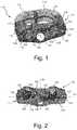
- FIG. 1is a bottom perspective view of an intervertebral implant according to an embodiment of the disclosure.
- FIG. 2is anterior elevation view of the intervertebral implant of FIG. 1 .
- FIG. 3is bottom plan view of the intervertebral implant of FIG. 1 .
- FIG. 4is a perspective view similar to FIG. 1 illustrating fasteners positioned within the implant.
- FIG. 5is a cross-sectional view of the anterior portion of the implant of FIG. 1 with a locking screw positioned therein.
- FIG. 6is a top plan view of the intervertebral implant of FIG. 1 positioned relative to a vertebra.
- FIG. 7is a perspective view illustrating the intervertebral implant of FIG. 1 connected to an insertion tool in accordance with an embodiment of the disclosure.
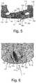
- FIGS. 8-10are perspective, side and elevation views, respectively, of a retraction blade in accordance with an embodiment of the disclosure.
- FIGS. 11-13are perspective, side and elevation views, respectively, of a retraction blade in accordance with another embodiment of the disclosure.
- FIG. 14is a perspective view of the retraction blade of FIGS. 8-10 positioned in a mounting system in accordance with an embodiment of the disclosure.
- Embodiments of the disclosureare generally directed to intervertebral implants, systems, and method of use thereof.
- the implant 110has a body 111 with a generally D-shaped configuration.
- the body 111is defined by a posterior end 112 , an anterior end 114 and side walls 116 and 118 extending therebetween.
- a hollow interior chamber 113is defined within an inner perimeter of the body 111 .
- the hollow interior chamber 113is configured to receive bone growth promoting materials.
- the implant 110has an upper surface 120 and a substantially parallel lower surface 122 . It is noted that in FIGS. 1-4 , the implant 110 is illustrated in an inverted position such that the lower or superior surface 122 is facing upward.
- the upper and lower surfaces 120 , 122define a plurality of serrations 117 along the side walls 116 , 118 and a plurality of serrations 119 along the posterior end 112 .
- the implant 110is illustrated and described with a body 111 having a specific configuration, the disclosure is not limited to such.
- the body 111may have various other configurations suitable for the disc space into which the implant 110 is intended.
- the posterior end 112may be formed with a taper or the implant 110 may have a wedge shape such that the entire body 111 tapers from the anterior end 114 to the posterior end 112 .
- the side walls 116 , 118may be angled toward one another rather than extending substantially parallel to one another.
- the body 111may have an adjustable configuration.
- the implant body 111will have a central axis CA extending from the anterior end 114 to the superior end 112 .
- the central axis CAis located at the junction between the mid transverse plane P 1 and the mid sagittal plane P 2 and extends in each of the planes P 1 , P 2 (see FIG. 2 ).
- the anterior end 114 of the implant 110includes a plurality of fastener holes 124 , 126 through which anchors 140 or screws 150 (see FIGS. 4 and 6 ) extend to anchor the implant onto the vertebral body.
- Each of the fastener holes 124 , 126has a central axis C 1 , C 2 , C 3 .
- the axes C 1 , C 2 , C 3may be angled superiorly or inferiorly relative to the transverse plane P 1 such that the fasteners will be directed toward the superior or inferior vertebral body.
- the axes C 1 , C 2 of fastener holes 124each extend inferiorly relative to the transverse plane P 1 and the axis C 3 of the fastener hole 126 extends superiorly relative to the transverse plane P 1 .
- Such configurationis not required and the implant may have other configurations with more or fewer holes and with different numbers of holes extending superiorly or inferiorly. Additionally, when utilizing anchors 140 such angling may not be as necessary or necessary at all since the curved configuration of the anchor blade body 142 is curved and will naturally extend superiorly or inferiorly.
- Secondary holes 125are provided to receive respective blocking set screws 160 (see FIG. 5 ).
- the secondary holes 125each extend along a central axis C 6 , C 7 .
- Each of the secondary hole axes C 6 , C 7is generally parallel to the transverse plane P 1 .
- a blind hole 127 with a slot 129 and a threaded hole 128are provided for receiving an instrument 170 that is used for inserting the implant 110 , as will be described hereinafter.
- the central axis C 4 of the blind hole 127 and the central axis C 5 of the threaded hole 128also are generally parallel to the transverse plane P 1 .
- each of the axes C 1 -C 7is also angled relative to the sagittal plane P 2 (and thereby the central axis CA) in the transverse direction to facilitate lateral insertion of the implant 110 .
- the axes C 1 and C 2are parallel to one another and each are angled relative the sagittal plane P 2 at an acute angle ⁇ .
- the axis C 3 of fastener hole 126will also be angled relative the sagittal plane P 2 at the acute angle ⁇ and will be parallel to the axes C 1 and C 2 .
- the angle ⁇is chosen to approximate the angle of the lateral insertion path A of the implant relative to the sagittal plane SP of the vertebral body 12 of the spine 10 as shown in FIG. 6 .
- the insertion tool 170to hold the implant for insertion along the path A and also allows the fasteners 140 , 150 to be delivered along the same path along which the insertion tool will extend.
- the central axis CA of the implant 110will extend approximately along the sagittal plane SP of the vertebral body 12 and the fasteners 140 , 150 may be easily directed into engagement with the superior and inferior vertebral bodies.
- the axis C 4 of the blind hole 127 and the axis C 5 of the threaded hole 128also extend parallel to the fastener hole axes C 1 -C 3 .
- the insertion tool 170may be delivered to the implant 110 along the path A and then a threaded connector (not shown) can be advanced parallel to the axis of the tool 170 .
- the axes C 6 , C 7 of the secondary holes 125also preferably extend parallel to the fastener hole axes C 1 -C 3 . With the shaft 162 of each blocking set screw 160 extending into a respective secondary hole 125 , the head 164 thereof will be co-axial with the secondary hole 125 .
- a driver(not shown) may be moved along at the same angle defined by the insertion tool 170 to engage the head 164 and move the set screw 160 from a non-blocking position, wherein the recess(es) 166 on the head 164 are aligned with a respective fastener hole 124 , 126 , to a blocking position wherein the head 164 overlies the fastener holes 124 , 126 .
- the insertion tool 170includes a main body 172 extending from a proximal end 171 to a distal end 173 along a tool central axis C 8 .
- the distal end 173defines a face 175 configured to engage the anterior end 114 of the implant 110 .
- the face 175is angled relative to the tool central axis C 8 such that upon mounting of the implant 110 on the tool 170 , the tool central axis C 8 will be parallel with the central axes C 1 -C 7 of the implant in the transverse direction.
- the tool body 172may define one or more openings 179 configured to mount other tools thereto, for example, an articulating table arm or a pushing handle (not shown).
- a pinextends from the tool face 175 at the location labeled 177 which aligns with the blind hole 127 of the implant.
- the pinextends along an axis C 9 which is parallel to the tool central axis C 8 such that the pin will extend into the blind hole 127 and the face 175 will extend along the anterior end 114 of the implant 110 .
- a threaded connectorextends through a passage in the insertion tool 170 such that the threaded connector extends from the face 175 at the location labeled 178 which aligns with the threaded hole 128 .
- the tool 170may include a handle portion 176 through which the connector passage extends.
- the threaded connector passageextends along an axis C 10 that is parallel with the tool central axis C 8 such that the threaded connector can be advanced into and threadably engage the threaded hole 128 , thereby mounting the implant 110 to the face 175 of the insertion tool 170 .
- the tool body 172defines fastener passages 182 , 184 (only two shown in FIG. 7 ) configured to align with each of the fastener holes 124 , 126 .
- the axes C 11 , C 12 , C 13 of the fastener passages 182 , 184extend parallel to the tool central axis C 8 .
- the fasteners 140 , 150may be easily passed through the insertion tool 170 into the respective fastener hole 124 , 126 .
- the passages 182 , 184may have corresponding curves (in the superior/inferior direction).
- An alignment hole 183 , 185 , 187extends into each of the fastener passages 182 , 184 .
- an opening 186extends into the body 172 to set screw passages 188 on either side of the tube 180 defining the fastener passage 182 .
- Each set screw passage 188aligns with a respective secondary hole 125 .
- the axes C 14 , C 15 of the set screw passages 188extend parallel to the tool central axis C 8 .
- a drive tool(not shown) may be passed through each set screw passage 188 to engage and rotate a respective set screw 160 .
- Alignment holes 189 , 190extend into each of the set screw passages 188 .
- each of the implant holescould include a ball and socket configuration which is lockable at a desired angle.
- the face of the insertion toolcould be pivotably adjustable to match the angle set for the implant holes.
- Other means for adjusting the angle of the holes and the tool passagesmay also be utilized.
- the implant 110 and insertion tool 170provide greater ease of use off-axis to disc spaces, for example, the L5-S1 disc space.
- Traditional ALIF implantsrequire a straight-on approach, which is made more difficult when the patient is positioned on their side.
- the angled approach to the disc space with the angled toolpaired with a matching angle by which the fixation is delivered and blocked in place facilitates operating on the L5-S1 disc space, or other desired disc spaces, via a lateral position, or “lateral ALIF”.
- Such lateral ALIFrequires retraction of different anatomy to access the disc space with a patient on their side.
- a retraction assembly 220which offers increased ability to adjust blade position as well as specific options for retracting the anatomy as it pertains to accessing the disc space with a patient on their side will be described.
- the blade 200includes a body 202 extending from a proximal end 201 to a distal end 203 .
- the distal end 203 of the body 202includes a portion 204 having a narrower width than the portion 208 at the proximal end 201 .
- the body 202may have a lateral curvature as illustrated.
- a curved tip 206is defined at the distal end 203 of the body 202 .
- the curved tip 206may also narrow as it moves distally.
- the narrow portion 204 and the curved tip 206allow for retraction of vasculature, for example, at the crotch of the bifurcation.
- the wider portion 208 at the proximal end 201provides better retraction of soft tissue.
- the bi-functionality of the blade 200serves well for a minimally invasive anterior approach where the vessels need to be mobilized.
- a flange portion 212extends from the proximal end 201 and supports a connecting member 214 configured to engage and mount to a pivoting member 250 of the retraction assembly 220 as will be described hereinafter.
- the blade 200 ′includes a body 202 ′ extending from a proximal end 201 ′ to a distal end 203 ′.
- the body 202 ′tapers in thickness from a thinner portion 205 at the proximal end 201 ′ to a thicker portion at the distal end 203 ′. This configuration serves to stiffen the blade 200 ′.
- the body 202 ′may have a lateral curvature as illustrated.
- a scalloped tip 209is defined at the distal end 203 ′ of the body 202 ′.
- the scalloped tip 209may be used to sit under bony anatomy and act as a lever for retracting soft tissue.
- a flange portion 212extends from the proximal end 201 ′ and supports a connecting member 214 configured to engage and mount to a pivoting member 250 of the retraction assembly 220 .
- the retraction assembly 220includes a mounting plate 222 with one or more mounts 224 extending therefrom.
- the mounts 224are configured for mounting directly to an articulating table arm 230 or other structure, for example, mounting to extensions which mount to a more traditional ring-based design.
- the table arm 230includes an arm 232 which terminates in a screw platform 234 supporting a connecting screw 236 .
- the connecting screw 236is positioned within the mount 224 and tightened such that the mount 234 is secured between the head of the screw 236 and the screw platform 234 to secure the mounting plate 222 .
- a cavity 225extends into the mounting plate 222 and is configured to receive a shaft 242 of a lateral adjustment arm 240 .
- the shaft 242defines a slot 244 into which an adjustment screw 226 of the mounting plate 222 extends.
- the screw 226engages within the slot 244 and thereby defines the range of later movement of the lateral adjustment arm 240 .
- the screw 226 and slot 244may have various adjustment configurations, for example, a friction lock, gear assembly, or a rack and pinion arrangement.
- the opposite end of the lateral adjustment arm 240defines a fork 248 with a pair of openings 249 on each side to support a pivot member 250 .
- the pivot member 250includes a body 252 with an opening configured to receive the blade connecting member 214 to mount the blade 200 on the assembly 220 .
- a pivot pin 256extends through the fork 248 and end of the pivot member body 250 such that the pivot member 250 is pivotally supported relative to the fork 248 .
- a pair of opposed extensions 254extend into the openings 249 and define the range of pivot.
- An adjustment screw 246 on the lateral adjustment arm 240engages an opposite end of the pivot member 250 such that rotation thereof causes the pivot member 250 , and thereby the blade 200 , to pivot. Pivoting of the blade 200 allows the blade 200 to change angulation to compensate for various anatomy and tissue.
Landscapes
- Health & Medical Sciences (AREA)
- Engineering & Computer Science (AREA)
- Biomedical Technology (AREA)
- Orthopedic Medicine & Surgery (AREA)
- Neurology (AREA)
- Transplantation (AREA)
- Heart & Thoracic Surgery (AREA)
- Oral & Maxillofacial Surgery (AREA)
- Cardiology (AREA)
- Vascular Medicine (AREA)
- Life Sciences & Earth Sciences (AREA)
- Animal Behavior & Ethology (AREA)
- General Health & Medical Sciences (AREA)
- Public Health (AREA)
- Veterinary Medicine (AREA)
- Physical Education & Sports Medicine (AREA)
- Prostheses (AREA)
Abstract
Description
Claims (7)
Priority Applications (6)
| Application Number | Priority Date | Filing Date | Title |
|---|---|---|---|
| US16/515,780US11160666B2 (en) | 2014-05-15 | 2019-07-18 | Laterally insertable intervertebral spinal implant |
| EP20185848.7AEP3766459B1 (en) | 2019-07-18 | 2020-07-15 | Laterally insertable intervertebral spinal implant |
| JP2020122917AJP7025486B2 (en) | 2019-07-18 | 2020-07-17 | Laterally insertable facet spinal implant |
| US17/493,890US11833060B2 (en) | 2014-05-15 | 2021-10-05 | Laterally insertable intervertebral spinal implant |
| US18/499,441US12245951B2 (en) | 2014-05-15 | 2023-11-01 | Laterally insertable intervertebral spinal implant |
| US19/051,582US20250177166A1 (en) | 2014-05-15 | 2025-02-12 | Laterally insertable intervertebral spinal implant |
Applications Claiming Priority (5)
| Application Number | Priority Date | Filing Date | Title |
|---|---|---|---|
| US14/278,898US9545320B2 (en) | 2014-05-15 | 2014-05-15 | Standalone interbody implants |
| US14/509,634US9968461B2 (en) | 2014-05-15 | 2014-10-08 | Standalone interbody implants |
| US15/954,655US10179053B2 (en) | 2014-05-15 | 2018-04-17 | Standalone interbody implants |
| US16/205,892US10925750B2 (en) | 2014-05-15 | 2018-11-30 | Standalone interbody implants |
| US16/515,780US11160666B2 (en) | 2014-05-15 | 2019-07-18 | Laterally insertable intervertebral spinal implant |
Related Parent Applications (1)
| Application Number | Title | Priority Date | Filing Date |
|---|---|---|---|
| US16/205,892Continuation-In-PartUS10925750B2 (en) | 2014-05-15 | 2018-11-30 | Standalone interbody implants |
Related Child Applications (1)
| Application Number | Title | Priority Date | Filing Date |
|---|---|---|---|
| US17/493,890DivisionUS11833060B2 (en) | 2014-05-15 | 2021-10-05 | Laterally insertable intervertebral spinal implant |
Publications (2)
| Publication Number | Publication Date |
|---|---|
| US20190336304A1 US20190336304A1 (en) | 2019-11-07 |
| US11160666B2true US11160666B2 (en) | 2021-11-02 |
Family
ID=68384380
Family Applications (4)
| Application Number | Title | Priority Date | Filing Date |
|---|---|---|---|
| US16/515,780Active2034-09-16US11160666B2 (en) | 2014-05-15 | 2019-07-18 | Laterally insertable intervertebral spinal implant |
| US17/493,890Active2034-09-22US11833060B2 (en) | 2014-05-15 | 2021-10-05 | Laterally insertable intervertebral spinal implant |
| US18/499,441ActiveUS12245951B2 (en) | 2014-05-15 | 2023-11-01 | Laterally insertable intervertebral spinal implant |
| US19/051,582PendingUS20250177166A1 (en) | 2014-05-15 | 2025-02-12 | Laterally insertable intervertebral spinal implant |
Family Applications After (3)
| Application Number | Title | Priority Date | Filing Date |
|---|---|---|---|
| US17/493,890Active2034-09-22US11833060B2 (en) | 2014-05-15 | 2021-10-05 | Laterally insertable intervertebral spinal implant |
| US18/499,441ActiveUS12245951B2 (en) | 2014-05-15 | 2023-11-01 | Laterally insertable intervertebral spinal implant |
| US19/051,582PendingUS20250177166A1 (en) | 2014-05-15 | 2025-02-12 | Laterally insertable intervertebral spinal implant |
Country Status (1)
| Country | Link |
|---|---|
| US (4) | US11160666B2 (en) |
Cited By (18)
| Publication number | Priority date | Publication date | Assignee | Title |
|---|---|---|---|---|
| US20220023063A1 (en)* | 2014-05-15 | 2022-01-27 | Globus Medical, Inc. | Laterally insertable intervertebral spinal implant |
| US11376134B1 (en) | 2020-11-05 | 2022-07-05 | Warsaw Orthopedic, Inc. | Dual expanding spinal implant, system, and method of use |
| US11395743B1 (en) | 2021-05-04 | 2022-07-26 | Warsaw Orthopedic, Inc. | Externally driven expandable interbody and related methods |
| US11517443B2 (en) | 2020-11-05 | 2022-12-06 | Warsaw Orthopedic, Inc. | Dual wedge expandable implant, system and method of use |
| US11517363B2 (en) | 2020-11-05 | 2022-12-06 | Warsaw Orthopedic, Inc. | Screw driver and complimentary screws |
| US11612499B2 (en) | 2021-06-24 | 2023-03-28 | Warsaw Orthopedic, Inc. | Expandable interbody implant |
| US11638653B2 (en) | 2020-11-05 | 2023-05-02 | Warsaw Orthopedic, Inc. | Surgery instruments with a movable handle |
| US11806250B2 (en) | 2018-02-22 | 2023-11-07 | Warsaw Orthopedic, Inc. | Expandable spinal implant system and method of using same |
| US11833059B2 (en) | 2020-11-05 | 2023-12-05 | Warsaw Orthopedic, Inc. | Expandable inter-body device, expandable plate system, and associated methods |
| US20240000580A1 (en)* | 2022-06-29 | 2024-01-04 | Astura Medical Inc. | Spinal interbody spacer |
| US11963881B2 (en) | 2020-11-05 | 2024-04-23 | Warsaw Orthopedic, Inc. | Expandable inter-body device, system, and method |
| US12121453B2 (en) | 2020-11-05 | 2024-10-22 | Warsaw Orthopedic, Inc. | Dual wedge expandable implant with eyelets, system, and method of use |
| US12171439B2 (en) | 2020-11-05 | 2024-12-24 | Warsaw Orthopedic, Inc. | Protected drill |
| US12239544B2 (en) | 2020-11-05 | 2025-03-04 | Warsaw Orthopedic, Inc. | Rhomboid shaped implants |
| US12295865B2 (en) | 2021-06-24 | 2025-05-13 | Warsaw Orthopedic, Inc. | Expandable interbody implant and corresponding inserter |
| US12318308B2 (en) | 2020-11-05 | 2025-06-03 | Warsaw Orthopedic, Inc. | Dual expandable inter-body device |
| US12414863B2 (en) | 2021-06-24 | 2025-09-16 | Warsaw Orthopedic, Inc. | Expandable interbody implant and corresponding surgical tool |
| US12440349B2 (en) | 2022-02-04 | 2025-10-14 | Warsaw Orthopedic, Inc. | Expandable interbody implant and breakoff screw |
Families Citing this family (5)
| Publication number | Priority date | Publication date | Assignee | Title |
|---|---|---|---|---|
| US11285014B1 (en) | 2020-11-05 | 2022-03-29 | Warsaw Orthopedic, Inc. | Expandable inter-body device, system, and method |
| US11291554B1 (en) | 2021-05-03 | 2022-04-05 | Medtronic, Inc. | Unibody dual expanding interbody implant |
| US12268614B2 (en) | 2021-06-24 | 2025-04-08 | Warsaw Orthopedic, Inc. | Interbody implant with adjusting shims |
| US11730608B2 (en) | 2021-07-13 | 2023-08-22 | Warsaw Orthopedic, Inc. | Monoblock expandable interbody implant |
| US11850163B2 (en) | 2022-02-01 | 2023-12-26 | Warsaw Orthopedic, Inc. | Interbody implant with adjusting shims |
Citations (160)
| Publication number | Priority date | Publication date | Assignee | Title |
|---|---|---|---|---|
| US1673630A (en) | 1925-06-11 | 1928-06-12 | Mechanical Rubber Co | Paving construction |
| US4349921A (en) | 1980-06-13 | 1982-09-21 | Kuntz J David | Intervertebral disc prosthesis |
| US4599086A (en) | 1985-06-07 | 1986-07-08 | Doty James R | Spine stabilization device and method |
| US4743256A (en) | 1985-10-04 | 1988-05-10 | Brantigan John W | Surgical prosthetic implant facilitating vertebral interbody fusion and method |
| US4834757A (en) | 1987-01-22 | 1989-05-30 | Brantigan John W | Prosthetic implant |
| US4904261A (en) | 1987-08-06 | 1990-02-27 | A. W. Showell (Surgicraft) Limited | Spinal implants |
| US4917704A (en) | 1987-07-09 | 1990-04-17 | Sulzer Brothers Limited | Intervertebral prosthesis |
| US4955908A (en) | 1987-07-09 | 1990-09-11 | Sulzer Brothers Limited | Metallic intervertebral prosthesis |
| US5002576A (en) | 1988-06-06 | 1991-03-26 | Mecron Medizinische Produkte Gmbh | Intervertebral disk endoprosthesis |
| US5364399A (en) | 1993-02-05 | 1994-11-15 | Danek Medical, Inc. | Anterior cervical plating system |
| US5397364A (en) | 1993-10-12 | 1995-03-14 | Danek Medical, Inc. | Anterior interbody fusion device |
| US5458641A (en) | 1993-09-08 | 1995-10-17 | Ramirez Jimenez; Juan J. | Vertebral body prosthesis |
| US5514180A (en) | 1994-01-14 | 1996-05-07 | Heggeness; Michael H. | Prosthetic intervertebral devices |
| FR2727003A1 (en) | 1994-11-18 | 1996-05-24 | Euros Sa | Lumbar-sacral vertebrae anterior stabiliser |
| US5549612A (en) | 1992-11-25 | 1996-08-27 | Codman & Shurtleff, Inc. | Osteosynthesis plate system |
| WO1997023175A1 (en) | 1995-12-21 | 1997-07-03 | Colorado | Interbody vertebral implant |
| US5645596A (en) | 1993-07-07 | 1997-07-08 | Asahi Kogaku Kogyo Kabushiki Kaisha | Ceramic vertebrae prosthesis |
| US5861041A (en) | 1997-04-07 | 1999-01-19 | Arthit Sitiso | Intervertebral disk prosthesis and method of making the same |
| US5888223A (en) | 1995-12-08 | 1999-03-30 | Bray, Jr.; Robert S. | Anterior stabilization device |
| WO1999063914A1 (en) | 1998-06-09 | 1999-12-16 | Henderson Fraser C | Fusion stabilization chamber |
| US6045579A (en) | 1997-05-01 | 2000-04-04 | Spinal Concepts, Inc. | Adjustable height fusion device |
| US6146421A (en) | 1997-08-04 | 2000-11-14 | Gordon, Maya, Roberts And Thomas, Number 1, Llc | Multiple axis intervertebral prosthesis |
| US6156037A (en) | 1998-10-28 | 2000-12-05 | Sdgi Holdings, Inc. | Anterior lateral spine cage-plate fixation device and technique |
| US6200347B1 (en) | 1999-01-05 | 2001-03-13 | Lifenet | Composite bone graft, method of making and using same |
| US6206922B1 (en) | 1995-03-27 | 2001-03-27 | Sdgi Holdings, Inc. | Methods and instruments for interbody fusion |
| US6231610B1 (en) | 1999-08-25 | 2001-05-15 | Allegiance Corporation | Anterior cervical column support device |
| US6235059B1 (en) | 1996-04-03 | 2001-05-22 | Scient'x (Societe A Responsabilite Limitee) | Intersomatic setting and fusion system |
| US6235033B1 (en) | 2000-04-19 | 2001-05-22 | Synthes (Usa) | Bone fixation assembly |
| US6258089B1 (en) | 1998-05-19 | 2001-07-10 | Alphatec Manufacturing, Inc. | Anterior cervical plate and fixation system |
| US20010034553A1 (en) | 2000-02-04 | 2001-10-25 | Michelson Gary Karlin | Expandable push-in arcuate interbody spinal fusion implant with tapered configuration during insertion |
| US20020004683A1 (en) | 2000-07-10 | 2002-01-10 | Michelson Gary K. | Flanged interbody spinal fusion implants |
| US20020010511A1 (en) | 2000-07-07 | 2002-01-24 | Michelson Gary Karlin | Expandable implant with interlocking walls |
| US6342074B1 (en) | 1999-04-30 | 2002-01-29 | Nathan S. Simpson | Anterior lumbar interbody fusion implant and method for fusing adjacent vertebrae |
| US20020016595A1 (en) | 1999-05-05 | 2002-02-07 | Gary K. Michelson | Screws of cortical bone and method of manufacture thereof |
| US6364880B1 (en) | 1994-03-28 | 2002-04-02 | Gary Karlin Michelson | Spinal implant with bone screws |
| US6383186B1 (en) | 1997-02-11 | 2002-05-07 | Gary K. Michelson | Single-lock skeletal plating system |
| US20020082597A1 (en) | 1999-11-24 | 2002-06-27 | Robert Fraser | Anterior lumbar interbody fusion cage with locking plate |
| US6425920B1 (en) | 1999-10-13 | 2002-07-30 | James S. Hamada | Spinal fusion implant |
| US20020138146A1 (en) | 2000-04-18 | 2002-09-26 | Jackson Roger P. | Anterior expandable spinal fusion cage system |
| US20020143399A1 (en) | 2001-04-02 | 2002-10-03 | Ulrich Gmbh & Co. Kg | Anchorable vertebral implant |
| US20020147450A1 (en) | 2001-04-06 | 2002-10-10 | Lehuec Jean-Charles | Anterior plating system and method |
| US6468311B2 (en)* | 2001-01-22 | 2002-10-22 | Sdgi Holdings, Inc. | Modular interbody fusion implant |
| US6482233B1 (en) | 1998-01-29 | 2002-11-19 | Synthes(U.S.A.) | Prosthetic interbody spacer |
| US6520993B2 (en) | 2000-12-29 | 2003-02-18 | Depuy Acromed, Inc. | Spinal implant |
| US20030045939A1 (en) | 2001-08-24 | 2003-03-06 | Simon Casutt | Artificial intervertebral disc |
| US6540785B1 (en) | 1998-10-22 | 2003-04-01 | Sdgi Holdings, Inc. | Artificial intervertebral joint permitting translational and rotational motion |
| US6558387B2 (en) | 2001-01-30 | 2003-05-06 | Fastemetix, Llc | Porous interbody fusion device having integrated polyaxial locking interference screws |
| US6558424B2 (en) | 2001-06-28 | 2003-05-06 | Depuy Acromed | Modular anatomic fusion device |
| US6558423B1 (en) | 1999-05-05 | 2003-05-06 | Gary K. Michelson | Interbody spinal fusion implants with multi-lock for locking opposed screws |
| US6562073B2 (en) | 2001-02-06 | 2003-05-13 | Sdgi Holding, Inc. | Spinal bone implant |
| US20030105528A1 (en) | 2001-12-05 | 2003-06-05 | Osteotech, Inc. | Spinal intervertebral implant, interconnections for such implant and processes for making |
| US20030125739A1 (en) | 2001-12-12 | 2003-07-03 | Bagga Charanpreet S. | Bioactive spinal implants and method of manufacture thereof |
| US20030167091A1 (en) | 2002-03-04 | 2003-09-04 | Scharf Michael S. | Spinal fixation device |
| US20030181981A1 (en) | 2000-05-11 | 2003-09-25 | Jean-Philippe Lemaire | Anterior lumbar interbody implant |
| US6629998B1 (en) | 2000-08-23 | 2003-10-07 | Chih-I Lin | Intervertebral retrieval device |
| US6666889B1 (en) | 1999-01-26 | 2003-12-23 | Scient'x (Societe Anonyme) | Intersomatic implant for sagittal insertion and suitable for being offset transversely in the frontal plane |
| US20040078078A1 (en) | 2002-10-18 | 2004-04-22 | Shepard Yolanda Denise | Cortical and cancellous allograft cervical fusion block |
| US20040082998A1 (en) | 2001-02-23 | 2004-04-29 | Kenichi Shinomiya | Artificial pyramid |
| US20040082999A1 (en) | 2001-01-30 | 2004-04-29 | Robert Mathys | Bone implant, in particular, an inter-vertebral implant |
| US6740118B2 (en) | 2002-01-09 | 2004-05-25 | Sdgi Holdings, Inc. | Intervertebral prosthetic joint |
| US20040117018A1 (en) | 1999-12-08 | 2004-06-17 | Michelson Gary K. | Spinal implant surface configuration with a projection having a back cut |
| US20040143332A1 (en) | 2002-10-31 | 2004-07-22 | Krueger David J. | Movable disc implant |
| US20040143270A1 (en) | 2002-10-29 | 2004-07-22 | St. Francis Medical Technologies, Inc. | Tools for implanting artificial vertebral disk and method |
| US20040176853A1 (en) | 2003-03-05 | 2004-09-09 | Sennett Andrew R. | Apparatus and method for spinal fusion using posteriorly implanted devices |
| US20040199253A1 (en)* | 2003-04-07 | 2004-10-07 | Cervitech, Inc. | Cervical intervertebral disk prosthesis |
| WO2005007040A1 (en) | 2003-07-22 | 2005-01-27 | Synthes Gmbh | Intervertebral implant comprising dome-shaped joint surfaces |
| US6849093B2 (en) | 2001-03-09 | 2005-02-01 | Gary K. Michelson | Expansion constraining member adapted for use with an expandable interbody spinal fusion implant and method for use thereof |
| US20050055098A1 (en) | 2003-09-10 | 2005-03-10 | Sdgi Holdings, Inc. | Artificial spinal discs and associated implantation and revision methods |
| US20050065607A1 (en) | 2003-09-24 | 2005-03-24 | Gross Jeffrey M. | Assembled fusion implant |
| US6899735B2 (en) | 2002-10-02 | 2005-05-31 | Sdgi Holdings, Inc. | Modular intervertebral prosthesis system |
| US20050149192A1 (en) | 2003-11-20 | 2005-07-07 | St. Francis Medical Technologies, Inc. | Intervertebral body fusion cage with keels and implantation method |
| US20050149193A1 (en) | 2003-11-20 | 2005-07-07 | St. Francis Medical Technology, Inc. | Intervertebral body fusion cage with keels and implantation methods |
| US20050159819A1 (en) | 2003-09-10 | 2005-07-21 | Sdgi Holdings, Inc. | Adjustable drill guide |
| US20050171607A1 (en) | 2000-06-13 | 2005-08-04 | Michelson Gary K. | Manufactured bone composite implant shaped to conform to a prepared implantation space |
| US20050177236A1 (en) | 2002-02-19 | 2005-08-11 | Claude Mathieu | Intervertebral implant |
| US20050187625A1 (en) | 2003-10-20 | 2005-08-25 | Howard Wolek | Vertebral body replacement apparatus and method |
| US20050240271A1 (en) | 2003-03-06 | 2005-10-27 | Spinecore, Inc. | Cervical disc replacement |
| US20050240267A1 (en) | 2004-03-26 | 2005-10-27 | Randall Brandon L | Allograft implant |
| US20050256574A1 (en) | 1998-01-30 | 2005-11-17 | Paul David C | Intervertebral allograft spacer |
| US6972019B2 (en) | 2001-01-23 | 2005-12-06 | Michelson Gary K | Interbody spinal implant with trailing end adapted to receive bone screws |
| US7001432B2 (en) | 2002-03-12 | 2006-02-21 | Cervitech, Inc. | Intervertebral prosthesis |
| US7025787B2 (en) | 2001-11-26 | 2006-04-11 | Sdgi Holdings, Inc. | Implantable joint prosthesis and associated instrumentation |
| US20060085071A1 (en) | 2003-02-06 | 2006-04-20 | Beat Lechmann | Intervertebral implant |
| US20060116767A1 (en) | 2002-11-14 | 2006-06-01 | Sepitec Foundation | Implant Used in Procedures for Stiffening the Vertebral Column |
| US20060129240A1 (en) | 2004-12-10 | 2006-06-15 | Joe Lessar | Implants based on engineered composite materials having enhanced imaging and wear resistance |
| US20060217809A1 (en) | 2005-03-24 | 2006-09-28 | Accin Corporation | Intervertebral disc replacement device |
| US7137997B2 (en) | 2003-12-29 | 2006-11-21 | Globus Medical, Inc. | Spinal fusion implant |
| US7147665B1 (en) | 1998-07-22 | 2006-12-12 | Sdgi Holdings, Inc. | Threaded cylindrical multidiscoid single or multiple array disc prosthesis |
| US7153325B2 (en) | 2003-08-01 | 2006-12-26 | Ultra-Kinetics, Inc. | Prosthetic intervertebral disc and methods for using the same |
| US7172627B2 (en) | 2001-04-03 | 2007-02-06 | Scient'x | Stabilized interbody fusion system for vertebrae |
| US7192447B2 (en) | 2002-12-19 | 2007-03-20 | Synthes (Usa) | Intervertebral implant |
| US20070088441A1 (en) | 2004-06-30 | 2007-04-19 | Synergy Disc Replacement, Inc. | Artificial Spinal Disc |
| US20070123987A1 (en) | 2005-11-02 | 2007-05-31 | Bernstein Avi J | Curvilinear cervical interbody device |
| US20070135923A1 (en) | 2005-12-14 | 2007-06-14 | Sdgi Holdings, Inc. | Ceramic and polymer prosthetic device |
| US20070162130A1 (en) | 2005-11-30 | 2007-07-12 | Ralph Rashbaum | Intervertebral disc prosthesis and instrumentation for insertion of the prosthesis between the vertebrae |
| US20070168032A1 (en) | 2006-01-13 | 2007-07-19 | Nabil L. Muhanna, M.D. | Flexible vertebral implant |
| WO2007098288A2 (en) | 2006-02-27 | 2007-08-30 | Synthes (U.S.A.) | Intervertebral implant with fixation geometry |
| US20070225812A1 (en) | 2003-10-30 | 2007-09-27 | Gill Steven S | Intervertebral Prosthesis |
| US20070225806A1 (en) | 2006-03-24 | 2007-09-27 | Sdgi Holdings, Inc. | Arthroplasty device |
| US20070225810A1 (en) | 2006-03-23 | 2007-09-27 | Dennis Colleran | Flexible cage spinal implant |
| US20070233253A1 (en) | 2003-04-21 | 2007-10-04 | Bray Robert S | Lateral mount implant device |
| US20070250167A1 (en) | 2003-04-21 | 2007-10-25 | Rsb Spine Llc | Spine implants |
| US20070270961A1 (en) | 2006-04-25 | 2007-11-22 | Sdgi Holdings, Inc. | Spinal implant with deployable and retractable barbs |
| US7309357B2 (en) | 2004-12-30 | 2007-12-18 | Infinesse, Corporation | Prosthetic spinal discs |
| US7320708B1 (en) | 2002-11-13 | 2008-01-22 | Sdgi Holdings, Inc. | Cervical interbody device |
| WO2008014258A2 (en) | 2006-07-24 | 2008-01-31 | Spine Solutions, Inc. | Intervertebral implant with keel |
| US20080046083A1 (en) | 2006-08-15 | 2008-02-21 | Motionback Llc | Spinal implant |
| US20080051907A1 (en) | 2004-01-30 | 2008-02-28 | Warsaw Orthopedic, Inc. | Anatomic Implants Designed to Minimize Instruments and Surgical Techniques |
| US20080051890A1 (en) | 2006-08-11 | 2008-02-28 | Warsaw Orthopedic, Inc. | Intervertebral Implants with Attachable Flanges and Methods of Use |
| US20080133013A1 (en) | 2004-06-30 | 2008-06-05 | Synergy Disc Replacement, Inc. | Artificial Spinal Disc |
| US20080281425A1 (en)* | 2007-02-21 | 2008-11-13 | John Thalgott | Orthopaedic Implants and Prostheses |
| US20080306596A1 (en)* | 2007-06-06 | 2008-12-11 | Jones Robert J | Interbody fusion device and associated methods |
| US20090076608A1 (en) | 2007-09-17 | 2009-03-19 | Vermillion Technologies, Llc | Intervertebral disc replacement prosthesis |
| US20090210062A1 (en) | 2008-02-20 | 2009-08-20 | John Thalgott | Orthopaedic Implants and Prostheses |
| US7594931B2 (en) | 2001-07-13 | 2009-09-29 | Ldr Medical | Vertebral cage device with modular fixation |
| US20100057206A1 (en)* | 2008-09-02 | 2010-03-04 | Duffield William E | Intervertebral fusion implant |
| US20100087925A1 (en) | 2008-10-08 | 2010-04-08 | K2M, Inc. | Spinal interbody spacer |
| US20100145460A1 (en) | 2008-11-07 | 2010-06-10 | Mcdonough William P | Zero-profile interbody spacer and coupled plate assembly |
| US7771475B2 (en) | 2002-02-02 | 2010-08-10 | Warsaw Orthopedic, Inc. | Spinal implant having deployable bone engaging projections |
| US20100312345A1 (en)* | 2009-06-04 | 2010-12-09 | Duffield William E | Intervertebral fusion implant |
| US20100312346A1 (en)* | 2007-11-16 | 2010-12-09 | Thomas Kueenzi | Low profile intervertebral implant |
| US7850731B2 (en) | 2006-10-04 | 2010-12-14 | Seaspine, Inc. | Articulating spinal implant |
| US20110166658A1 (en) | 2009-11-09 | 2011-07-07 | Centinel Spine, Inc. | Spinal implant with attachment system |
| US20110251689A1 (en) | 2010-04-08 | 2011-10-13 | Seifert Jody L | Intervertebral Implant |
| US8100976B2 (en) | 2003-04-21 | 2012-01-24 | Rsb Spine Llc | Implant subsidence control |
| US8114162B1 (en) | 2006-08-09 | 2012-02-14 | Nuvasive, Inc. | Spinal fusion implant and related methods |
| US8137403B2 (en) | 2001-04-02 | 2012-03-20 | Warsaw Orthopedic, Inc. | Hemi-interbody spinal fusion implants manufactured from a major long bone ring |
| US20120078371A1 (en) | 2010-09-23 | 2012-03-29 | Thomas Gamache | Fusion cage with in-line single piece fixation |
| US20120078373A1 (en) | 2010-09-23 | 2012-03-29 | Thomas Gamache | Stand alone intervertebral fusion device |
| US8216312B2 (en) | 2007-05-31 | 2012-07-10 | Zimmer Spine, Inc. | Spinal interbody system and method |
| US20120179259A1 (en)* | 2010-12-21 | 2012-07-12 | Mcdonough William P | Intervertebral implants, systems, and methods of use |
| WO2012115631A1 (en) | 2011-02-23 | 2012-08-30 | Synthes Usa, Llc | Expandable interbody fusion implant |
| US8268000B2 (en) | 2007-04-03 | 2012-09-18 | Warsaw Orthopedic, Inc. | Composite interbody spacer |
| US20120245690A1 (en) | 2009-09-06 | 2012-09-27 | Cowan Jr John A | Locking spinal fusion device |
| US20120290089A1 (en) | 2011-05-10 | 2012-11-15 | Melamed Hooman M | Vertebral spacer |
| US8343222B2 (en) | 2005-04-28 | 2013-01-01 | Aiden Cope | Spinal disc prosthesis and instruments |
| US8425607B2 (en) | 2007-04-03 | 2013-04-23 | Warsaw Orthopedic, Inc. | Anchor member locking features |
| US20130110247A1 (en) | 2011-11-01 | 2013-05-02 | Amedica Corporation | Implants with a Connectable Insert and Related Systems and Methods |
| US8486149B2 (en)* | 2011-02-23 | 2013-07-16 | DePuy Synthes Products, LLC | Expandable interbody fusion implant |
| US20140012380A1 (en) | 2012-06-29 | 2014-01-09 | DuPuy Synthes Products, LLC | Lateral insertion spinal implant |
| US20140039623A1 (en)* | 2012-08-03 | 2014-02-06 | Andrew Iott | Stabilizing Joints |
| US20140180422A1 (en)* | 2011-09-16 | 2014-06-26 | Globus Medical, Inc. | Low Profile Plate |
| US20140228957A1 (en)* | 2013-02-14 | 2014-08-14 | Globus Medical, Inc. | Devices and Methods for Correcting Vertebral Misalignment |
| US20140228959A1 (en)* | 2013-02-14 | 2014-08-14 | Globus Medical, Inc | Devices and Methods for Correcting Vertebral Misalignment |
| US20140228958A1 (en)* | 2013-02-14 | 2014-08-14 | Marcin Niemiec | Devices and Methods for Correcting Vertebral Misalignment |
| US20140243981A1 (en)* | 2013-02-25 | 2014-08-28 | Globus Medical, Inc. | Expandable Intervertebral Implant |
| US20140257487A1 (en)* | 2013-03-05 | 2014-09-11 | Globus Medical, Inc. | Low Profile Plate |
| WO2014138311A1 (en) | 2013-03-05 | 2014-09-12 | Globus Medical, Inc. | Low profile plate |
| US20140277497A1 (en)* | 2013-03-15 | 2014-09-18 | Globus Medical, Inc. | Interbody Standalone Intervertebral Implant |
| US20140277488A1 (en)* | 2013-03-15 | 2014-09-18 | Daniel Davenport | Expandable Intervertebral Implant |
| US20140277489A1 (en)* | 2013-03-15 | 2014-09-18 | Daniel Davenport | Expandable Intervertebral Implant |
| US20140277487A1 (en)* | 2013-03-15 | 2014-09-18 | Dan Davenport | Expandable Intervertebral Implant |
| US20150190241A1 (en) | 2014-01-09 | 2015-07-09 | Warsaw Orthopedic, Inc. | Spinal implant system and method |
| US20150328007A1 (en)* | 2014-05-15 | 2015-11-19 | Globus Medical, Inc | Standalone Interbody Implants |
| US20150328010A1 (en)* | 2014-05-15 | 2015-11-19 | Globus Medical, Inc. | Standalone interbody implants |
| US20150328009A1 (en)* | 2014-05-15 | 2015-11-19 | Globus Medical, Inc. | Standalone Interbody Implants |
| US9277946B2 (en)* | 2011-09-06 | 2016-03-08 | Amendia, Inc. | Spinal fusion system |
| US20160095714A1 (en)* | 2011-09-16 | 2016-04-07 | Globus Medical, Inc. | Low profile plate |
| US20170049579A1 (en)* | 2015-08-19 | 2017-02-23 | Raymond J. Quinlan | Spinal Fusion Device And Method Of Using Same |
| US20190336304A1 (en)* | 2014-05-15 | 2019-11-07 | Globus Medical, Inc. | Laterally insertable intervertebral spinal implant |
Family Cites Families (7)
| Publication number | Priority date | Publication date | Assignee | Title |
|---|---|---|---|---|
| US9597095B2 (en)* | 2009-05-15 | 2017-03-21 | Globus Medical, Inc | Screw guide and tissue retractor instrument |
| WO2014145766A1 (en) | 2013-03-15 | 2014-09-18 | Paradigm Spine, Llc | Modular, customizable spine stabilization system |
| CA2874390C (en)* | 2013-12-13 | 2018-03-06 | Stryker European Holdings I, Llc | Tissue retraction and vertebral displacement devices, systems, and methods for posterior spinal fusion |
| US11013616B2 (en)* | 2018-10-10 | 2021-05-25 | K2M, Inc. | Sagittal balance systems and methods of use thereof |
| US12185987B2 (en)* | 2020-10-02 | 2025-01-07 | Atlas Spine, Inc. | Bone anchor based retractor/distractor |
| US11826031B2 (en)* | 2020-12-09 | 2023-11-28 | Alphatec Spine, Inc. | Surgical retractors and methods of using the same |
| TWI776602B (en)* | 2021-07-22 | 2022-09-01 | 醫百科技股份有限公司 | surgical spreader |
- 2019
- 2019-07-18USUS16/515,780patent/US11160666B2/enactiveActive
- 2021
- 2021-10-05USUS17/493,890patent/US11833060B2/enactiveActive
- 2023
- 2023-11-01USUS18/499,441patent/US12245951B2/enactiveActive
- 2025
- 2025-02-12USUS19/051,582patent/US20250177166A1/enactivePending
Patent Citations (211)
| Publication number | Priority date | Publication date | Assignee | Title |
|---|---|---|---|---|
| US1673630A (en) | 1925-06-11 | 1928-06-12 | Mechanical Rubber Co | Paving construction |
| US4349921A (en) | 1980-06-13 | 1982-09-21 | Kuntz J David | Intervertebral disc prosthesis |
| US4599086A (en) | 1985-06-07 | 1986-07-08 | Doty James R | Spine stabilization device and method |
| US4743256A (en) | 1985-10-04 | 1988-05-10 | Brantigan John W | Surgical prosthetic implant facilitating vertebral interbody fusion and method |
| US4834757A (en) | 1987-01-22 | 1989-05-30 | Brantigan John W | Prosthetic implant |
| US4917704A (en) | 1987-07-09 | 1990-04-17 | Sulzer Brothers Limited | Intervertebral prosthesis |
| US4955908A (en) | 1987-07-09 | 1990-09-11 | Sulzer Brothers Limited | Metallic intervertebral prosthesis |
| US4904261A (en) | 1987-08-06 | 1990-02-27 | A. W. Showell (Surgicraft) Limited | Spinal implants |
| US5002576A (en) | 1988-06-06 | 1991-03-26 | Mecron Medizinische Produkte Gmbh | Intervertebral disk endoprosthesis |
| US5549612A (en) | 1992-11-25 | 1996-08-27 | Codman & Shurtleff, Inc. | Osteosynthesis plate system |
| US5364399A (en) | 1993-02-05 | 1994-11-15 | Danek Medical, Inc. | Anterior cervical plating system |
| US6066175A (en) | 1993-02-16 | 2000-05-23 | Henderson; Fraser C. | Fusion stabilization chamber |
| US5645596A (en) | 1993-07-07 | 1997-07-08 | Asahi Kogaku Kogyo Kabushiki Kaisha | Ceramic vertebrae prosthesis |
| US5458641A (en) | 1993-09-08 | 1995-10-17 | Ramirez Jimenez; Juan J. | Vertebral body prosthesis |
| US5397364A (en) | 1993-10-12 | 1995-03-14 | Danek Medical, Inc. | Anterior interbody fusion device |
| US5514180A (en) | 1994-01-14 | 1996-05-07 | Heggeness; Michael H. | Prosthetic intervertebral devices |
| US6364880B1 (en) | 1994-03-28 | 2002-04-02 | Gary Karlin Michelson | Spinal implant with bone screws |
| FR2727003A1 (en) | 1994-11-18 | 1996-05-24 | Euros Sa | Lumbar-sacral vertebrae anterior stabiliser |
| US20010005796A1 (en) | 1995-03-27 | 2001-06-28 | Thomas Zdeblick | Methods and instruments for interbody fusion |
| US6471724B2 (en) | 1995-03-27 | 2002-10-29 | Sdgi Holdings, Inc. | Methods and instruments for interbody fusion |
| US6206922B1 (en) | 1995-03-27 | 2001-03-27 | Sdgi Holdings, Inc. | Methods and instruments for interbody fusion |
| US5888223A (en) | 1995-12-08 | 1999-03-30 | Bray, Jr.; Robert S. | Anterior stabilization device |
| WO1997023175A1 (en) | 1995-12-21 | 1997-07-03 | Colorado | Interbody vertebral implant |
| US6235059B1 (en) | 1996-04-03 | 2001-05-22 | Scient'x (Societe A Responsabilite Limitee) | Intersomatic setting and fusion system |
| US6383186B1 (en) | 1997-02-11 | 2002-05-07 | Gary K. Michelson | Single-lock skeletal plating system |
| US5861041A (en) | 1997-04-07 | 1999-01-19 | Arthit Sitiso | Intervertebral disk prosthesis and method of making the same |
| US6045579A (en) | 1997-05-01 | 2000-04-04 | Spinal Concepts, Inc. | Adjustable height fusion device |
| US6146421A (en) | 1997-08-04 | 2000-11-14 | Gordon, Maya, Roberts And Thomas, Number 1, Llc | Multiple axis intervertebral prosthesis |
| US6482233B1 (en) | 1998-01-29 | 2002-11-19 | Synthes(U.S.A.) | Prosthetic interbody spacer |
| US20050256574A1 (en) | 1998-01-30 | 2005-11-17 | Paul David C | Intervertebral allograft spacer |
| US6258089B1 (en) | 1998-05-19 | 2001-07-10 | Alphatec Manufacturing, Inc. | Anterior cervical plate and fixation system |
| WO1999063914A1 (en) | 1998-06-09 | 1999-12-16 | Henderson Fraser C | Fusion stabilization chamber |
| US7147665B1 (en) | 1998-07-22 | 2006-12-12 | Sdgi Holdings, Inc. | Threaded cylindrical multidiscoid single or multiple array disc prosthesis |
| US6540785B1 (en) | 1998-10-22 | 2003-04-01 | Sdgi Holdings, Inc. | Artificial intervertebral joint permitting translational and rotational motion |
| US6156037A (en) | 1998-10-28 | 2000-12-05 | Sdgi Holdings, Inc. | Anterior lateral spine cage-plate fixation device and technique |
| US6200347B1 (en) | 1999-01-05 | 2001-03-13 | Lifenet | Composite bone graft, method of making and using same |
| US6666889B1 (en) | 1999-01-26 | 2003-12-23 | Scient'x (Societe Anonyme) | Intersomatic implant for sagittal insertion and suitable for being offset transversely in the frontal plane |
| US6342074B1 (en) | 1999-04-30 | 2002-01-29 | Nathan S. Simpson | Anterior lumbar interbody fusion implant and method for fusing adjacent vertebrae |
| US6558423B1 (en) | 1999-05-05 | 2003-05-06 | Gary K. Michelson | Interbody spinal fusion implants with multi-lock for locking opposed screws |
| US20020016595A1 (en) | 1999-05-05 | 2002-02-07 | Gary K. Michelson | Screws of cortical bone and method of manufacture thereof |
| US6231610B1 (en) | 1999-08-25 | 2001-05-15 | Allegiance Corporation | Anterior cervical column support device |
| US6425920B1 (en) | 1999-10-13 | 2002-07-30 | James S. Hamada | Spinal fusion implant |
| US20020082597A1 (en) | 1999-11-24 | 2002-06-27 | Robert Fraser | Anterior lumbar interbody fusion cage with locking plate |
| US6432106B1 (en) | 1999-11-24 | 2002-08-13 | Depuy Acromed, Inc. | Anterior lumbar interbody fusion cage with locking plate |
| US20040117018A1 (en) | 1999-12-08 | 2004-06-17 | Michelson Gary K. | Spinal implant surface configuration with a projection having a back cut |
| US6827740B1 (en) | 1999-12-08 | 2004-12-07 | Gary K. Michelson | Spinal implant surface configuration |
| US7972381B2 (en) | 1999-12-08 | 2011-07-05 | Warsaw Orthopedic, Inc. | Spinal implant surface configuration with a projection having a back cut |
| US6709458B2 (en) | 2000-02-04 | 2004-03-23 | Gary Karlin Michelson | Expandable push-in arcuate interbody spinal fusion implant with tapered configuration during insertion |
| US20010034553A1 (en) | 2000-02-04 | 2001-10-25 | Michelson Gary Karlin | Expandable push-in arcuate interbody spinal fusion implant with tapered configuration during insertion |
| US6835206B2 (en) | 2000-04-18 | 2004-12-28 | Roger P. Jackson | Anterior expandable spinal fusion cage system |
| US20020138146A1 (en) | 2000-04-18 | 2002-09-26 | Jackson Roger P. | Anterior expandable spinal fusion cage system |
| US6235033B1 (en) | 2000-04-19 | 2001-05-22 | Synthes (Usa) | Bone fixation assembly |
| US20030181981A1 (en) | 2000-05-11 | 2003-09-25 | Jean-Philippe Lemaire | Anterior lumbar interbody implant |
| US8105383B2 (en) | 2000-06-13 | 2012-01-31 | Warsaw Orthopedic, Inc. | Manufactured bone composite implant shaped to conform to a prepared implantation space |
| US20050171607A1 (en) | 2000-06-13 | 2005-08-04 | Michelson Gary K. | Manufactured bone composite implant shaped to conform to a prepared implantation space |
| US20020010511A1 (en) | 2000-07-07 | 2002-01-24 | Michelson Gary Karlin | Expandable implant with interlocking walls |
| US6730127B2 (en) | 2000-07-10 | 2004-05-04 | Gary K. Michelson | Flanged interbody spinal fusion implants |
| US7163561B2 (en) | 2000-07-10 | 2007-01-16 | Warsaw Orthopedic, Inc. | Flanged interbody spinal fusion implants |
| US20070106388A1 (en) | 2000-07-10 | 2007-05-10 | Sdgi Holdings, Inc. | Flanged interbody spinal fusion implants |
| US20020004683A1 (en) | 2000-07-10 | 2002-01-10 | Michelson Gary K. | Flanged interbody spinal fusion implants |
| US8323343B2 (en) | 2000-07-10 | 2012-12-04 | Warsaw Orthopedic, Inc. | Flanged interbody spinal fusion implants |
| US6629998B1 (en) | 2000-08-23 | 2003-10-07 | Chih-I Lin | Intervertebral retrieval device |
| US6520993B2 (en) | 2000-12-29 | 2003-02-18 | Depuy Acromed, Inc. | Spinal implant |
| US6468311B2 (en)* | 2001-01-22 | 2002-10-22 | Sdgi Holdings, Inc. | Modular interbody fusion implant |
| US7794502B2 (en) | 2001-01-23 | 2010-09-14 | Warsaw Orthopedic, Inc. | Implant with openings adapted to receive bone screws |
| US6972019B2 (en) | 2001-01-23 | 2005-12-06 | Michelson Gary K | Interbody spinal implant with trailing end adapted to receive bone screws |
| US6558387B2 (en) | 2001-01-30 | 2003-05-06 | Fastemetix, Llc | Porous interbody fusion device having integrated polyaxial locking interference screws |
| US20040082999A1 (en) | 2001-01-30 | 2004-04-29 | Robert Mathys | Bone implant, in particular, an inter-vertebral implant |
| US7044972B2 (en) | 2001-01-30 | 2006-05-16 | Synthes Ag Chur | Bone implant, in particular, an inter-vertebral implant |
| US6562073B2 (en) | 2001-02-06 | 2003-05-13 | Sdgi Holding, Inc. | Spinal bone implant |
| US6887272B2 (en) | 2001-02-23 | 2005-05-03 | Japan Science And Technology Agency | Artificial pyramid |
| US20040082998A1 (en) | 2001-02-23 | 2004-04-29 | Kenichi Shinomiya | Artificial pyramid |
| US6849093B2 (en) | 2001-03-09 | 2005-02-01 | Gary K. Michelson | Expansion constraining member adapted for use with an expandable interbody spinal fusion implant and method for use thereof |
| US6805714B2 (en) | 2001-04-02 | 2004-10-19 | Ulrich Gmbh & Co. Kg | Anchorable vertebral implant |
| US8137403B2 (en) | 2001-04-02 | 2012-03-20 | Warsaw Orthopedic, Inc. | Hemi-interbody spinal fusion implants manufactured from a major long bone ring |
| US20020143399A1 (en) | 2001-04-02 | 2002-10-03 | Ulrich Gmbh & Co. Kg | Anchorable vertebral implant |
| US7172627B2 (en) | 2001-04-03 | 2007-02-06 | Scient'x | Stabilized interbody fusion system for vertebrae |
| US20020147450A1 (en) | 2001-04-06 | 2002-10-10 | Lehuec Jean-Charles | Anterior plating system and method |
| US6793658B2 (en) | 2001-04-06 | 2004-09-21 | Society De Fabrication De Material Orthopedique, S.A. | Anterior plating system and method |
| US6558424B2 (en) | 2001-06-28 | 2003-05-06 | Depuy Acromed | Modular anatomic fusion device |
| US7594931B2 (en) | 2001-07-13 | 2009-09-29 | Ldr Medical | Vertebral cage device with modular fixation |
| US20030045939A1 (en) | 2001-08-24 | 2003-03-06 | Simon Casutt | Artificial intervertebral disc |
| US7025787B2 (en) | 2001-11-26 | 2006-04-11 | Sdgi Holdings, Inc. | Implantable joint prosthesis and associated instrumentation |
| US20030105528A1 (en) | 2001-12-05 | 2003-06-05 | Osteotech, Inc. | Spinal intervertebral implant, interconnections for such implant and processes for making |
| US20030125739A1 (en) | 2001-12-12 | 2003-07-03 | Bagga Charanpreet S. | Bioactive spinal implants and method of manufacture thereof |
| US7238203B2 (en) | 2001-12-12 | 2007-07-03 | Vita Special Purpose Corporation | Bioactive spinal implants and method of manufacture thereof |
| US6740118B2 (en) | 2002-01-09 | 2004-05-25 | Sdgi Holdings, Inc. | Intervertebral prosthetic joint |
| US7771475B2 (en) | 2002-02-02 | 2010-08-10 | Warsaw Orthopedic, Inc. | Spinal implant having deployable bone engaging projections |
| US20050177236A1 (en) | 2002-02-19 | 2005-08-11 | Claude Mathieu | Intervertebral implant |
| US7232464B2 (en) | 2002-02-19 | 2007-06-19 | Synthes (Usa) | Intervertebral implant |
| US7618456B2 (en) | 2002-02-19 | 2009-11-17 | Synthes Usa, Llc | Intervertebral implant |
| US7875076B2 (en) | 2002-02-19 | 2011-01-25 | Synthes Usa, Llc | Intervertebral implant |
| US6682563B2 (en) | 2002-03-04 | 2004-01-27 | Michael S. Scharf | Spinal fixation device |
| US20030167091A1 (en) | 2002-03-04 | 2003-09-04 | Scharf Michael S. | Spinal fixation device |
| US7001432B2 (en) | 2002-03-12 | 2006-02-21 | Cervitech, Inc. | Intervertebral prosthesis |
| US6899735B2 (en) | 2002-10-02 | 2005-05-31 | Sdgi Holdings, Inc. | Modular intervertebral prosthesis system |
| US20040078078A1 (en) | 2002-10-18 | 2004-04-22 | Shepard Yolanda Denise | Cortical and cancellous allograft cervical fusion block |
| US20040143270A1 (en) | 2002-10-29 | 2004-07-22 | St. Francis Medical Technologies, Inc. | Tools for implanting artificial vertebral disk and method |
| US20040143332A1 (en) | 2002-10-31 | 2004-07-22 | Krueger David J. | Movable disc implant |
| US7320708B1 (en) | 2002-11-13 | 2008-01-22 | Sdgi Holdings, Inc. | Cervical interbody device |
| US20060116767A1 (en) | 2002-11-14 | 2006-06-01 | Sepitec Foundation | Implant Used in Procedures for Stiffening the Vertebral Column |
| US7192447B2 (en) | 2002-12-19 | 2007-03-20 | Synthes (Usa) | Intervertebral implant |
| US20110087327A1 (en) | 2003-02-06 | 2011-04-14 | Beat Lechmann | Intervertebral implant |
| US20060085071A1 (en) | 2003-02-06 | 2006-04-20 | Beat Lechmann | Intervertebral implant |
| US7862616B2 (en) | 2003-02-06 | 2011-01-04 | Synthes Usa, Llc | Intervertebral implant |
| US7846207B2 (en) | 2003-02-06 | 2010-12-07 | Synthes Usa, Llc | Intervertebral implant |
| US20040176853A1 (en) | 2003-03-05 | 2004-09-09 | Sennett Andrew R. | Apparatus and method for spinal fusion using posteriorly implanted devices |
| US20050240271A1 (en) | 2003-03-06 | 2005-10-27 | Spinecore, Inc. | Cervical disc replacement |
| US20040199253A1 (en)* | 2003-04-07 | 2004-10-07 | Cervitech, Inc. | Cervical intervertebral disk prosthesis |
| US20070233253A1 (en) | 2003-04-21 | 2007-10-04 | Bray Robert S | Lateral mount implant device |
| US8100976B2 (en) | 2003-04-21 | 2012-01-24 | Rsb Spine Llc | Implant subsidence control |
| US20070250167A1 (en) | 2003-04-21 | 2007-10-25 | Rsb Spine Llc | Spine implants |
| WO2005007040A1 (en) | 2003-07-22 | 2005-01-27 | Synthes Gmbh | Intervertebral implant comprising dome-shaped joint surfaces |
| US7153325B2 (en) | 2003-08-01 | 2006-12-26 | Ultra-Kinetics, Inc. | Prosthetic intervertebral disc and methods for using the same |
| US20050055098A1 (en) | 2003-09-10 | 2005-03-10 | Sdgi Holdings, Inc. | Artificial spinal discs and associated implantation and revision methods |
| US7276082B2 (en) | 2003-09-10 | 2007-10-02 | Warsaw Orthopedic, Inc. | Artificial spinal discs and associated implantation and revision methods |
| US20050159819A1 (en) | 2003-09-10 | 2005-07-21 | Sdgi Holdings, Inc. | Adjustable drill guide |
| US20050065607A1 (en) | 2003-09-24 | 2005-03-24 | Gross Jeffrey M. | Assembled fusion implant |
| US20050187625A1 (en) | 2003-10-20 | 2005-08-25 | Howard Wolek | Vertebral body replacement apparatus and method |
| US20070225812A1 (en) | 2003-10-30 | 2007-09-27 | Gill Steven S | Intervertebral Prosthesis |
| US20050149193A1 (en) | 2003-11-20 | 2005-07-07 | St. Francis Medical Technology, Inc. | Intervertebral body fusion cage with keels and implantation methods |
| US20050149192A1 (en) | 2003-11-20 | 2005-07-07 | St. Francis Medical Technologies, Inc. | Intervertebral body fusion cage with keels and implantation method |
| US7137997B2 (en) | 2003-12-29 | 2006-11-21 | Globus Medical, Inc. | Spinal fusion implant |
| US20080051907A1 (en) | 2004-01-30 | 2008-02-28 | Warsaw Orthopedic, Inc. | Anatomic Implants Designed to Minimize Instruments and Surgical Techniques |
| US20050240267A1 (en) | 2004-03-26 | 2005-10-27 | Randall Brandon L | Allograft implant |
| US20080133013A1 (en) | 2004-06-30 | 2008-06-05 | Synergy Disc Replacement, Inc. | Artificial Spinal Disc |
| US20070088441A1 (en) | 2004-06-30 | 2007-04-19 | Synergy Disc Replacement, Inc. | Artificial Spinal Disc |
| US20060129240A1 (en) | 2004-12-10 | 2006-06-15 | Joe Lessar | Implants based on engineered composite materials having enhanced imaging and wear resistance |
| US7309357B2 (en) | 2004-12-30 | 2007-12-18 | Infinesse, Corporation | Prosthetic spinal discs |
| US20060217809A1 (en) | 2005-03-24 | 2006-09-28 | Accin Corporation | Intervertebral disc replacement device |
| US8343222B2 (en) | 2005-04-28 | 2013-01-01 | Aiden Cope | Spinal disc prosthesis and instruments |
| US20070123987A1 (en) | 2005-11-02 | 2007-05-31 | Bernstein Avi J | Curvilinear cervical interbody device |
| US20070162130A1 (en) | 2005-11-30 | 2007-07-12 | Ralph Rashbaum | Intervertebral disc prosthesis and instrumentation for insertion of the prosthesis between the vertebrae |
| US20070135923A1 (en) | 2005-12-14 | 2007-06-14 | Sdgi Holdings, Inc. | Ceramic and polymer prosthetic device |
| US20070168032A1 (en) | 2006-01-13 | 2007-07-19 | Nabil L. Muhanna, M.D. | Flexible vertebral implant |
| WO2007098288A2 (en) | 2006-02-27 | 2007-08-30 | Synthes (U.S.A.) | Intervertebral implant with fixation geometry |
| US20070225810A1 (en) | 2006-03-23 | 2007-09-27 | Dennis Colleran | Flexible cage spinal implant |
| US20070225806A1 (en) | 2006-03-24 | 2007-09-27 | Sdgi Holdings, Inc. | Arthroplasty device |
| US20070270961A1 (en) | 2006-04-25 | 2007-11-22 | Sdgi Holdings, Inc. | Spinal implant with deployable and retractable barbs |
| WO2008014258A2 (en) | 2006-07-24 | 2008-01-31 | Spine Solutions, Inc. | Intervertebral implant with keel |
| US8114162B1 (en) | 2006-08-09 | 2012-02-14 | Nuvasive, Inc. | Spinal fusion implant and related methods |
| US20080051890A1 (en) | 2006-08-11 | 2008-02-28 | Warsaw Orthopedic, Inc. | Intervertebral Implants with Attachable Flanges and Methods of Use |
| US20080046083A1 (en) | 2006-08-15 | 2008-02-21 | Motionback Llc | Spinal implant |
| US7850731B2 (en) | 2006-10-04 | 2010-12-14 | Seaspine, Inc. | Articulating spinal implant |
| US20080281425A1 (en)* | 2007-02-21 | 2008-11-13 | John Thalgott | Orthopaedic Implants and Prostheses |
| US8425607B2 (en) | 2007-04-03 | 2013-04-23 | Warsaw Orthopedic, Inc. | Anchor member locking features |
| US8268000B2 (en) | 2007-04-03 | 2012-09-18 | Warsaw Orthopedic, Inc. | Composite interbody spacer |
| US8216312B2 (en) | 2007-05-31 | 2012-07-10 | Zimmer Spine, Inc. | Spinal interbody system and method |
| US20080306596A1 (en)* | 2007-06-06 | 2008-12-11 | Jones Robert J | Interbody fusion device and associated methods |
| US8273127B2 (en)* | 2007-06-06 | 2012-09-25 | Spinesmith Partners, L.P. | Interbody fusion device and associated methods |
| US20090076608A1 (en) | 2007-09-17 | 2009-03-19 | Vermillion Technologies, Llc | Intervertebral disc replacement prosthesis |
| US20100312346A1 (en)* | 2007-11-16 | 2010-12-09 | Thomas Kueenzi | Low profile intervertebral implant |
| JP2011502708A (en) | 2007-11-16 | 2011-01-27 | ジンテス ゲゼルシャフト ミット ベシュレンクテル ハフツング | Low profile intervertebral implant |
| US8540774B2 (en) | 2007-11-16 | 2013-09-24 | DePuy Synthes Products, LLC | Low profile intervertebral implant |
| US20090210062A1 (en) | 2008-02-20 | 2009-08-20 | John Thalgott | Orthopaedic Implants and Prostheses |
| US20100057206A1 (en)* | 2008-09-02 | 2010-03-04 | Duffield William E | Intervertebral fusion implant |
| US8328872B2 (en) | 2008-09-02 | 2012-12-11 | Globus Medical, Inc. | Intervertebral fusion implant |
| US8439977B2 (en) | 2008-10-08 | 2013-05-14 | K2M, Inc. | Spinal interbody spacer |
| US20100087925A1 (en) | 2008-10-08 | 2010-04-08 | K2M, Inc. | Spinal interbody spacer |
| US8137405B2 (en) | 2008-10-08 | 2012-03-20 | K2M, Inc. | Spinal interbody spacer |
| US20100145460A1 (en) | 2008-11-07 | 2010-06-10 | Mcdonough William P | Zero-profile interbody spacer and coupled plate assembly |
| US20100312345A1 (en)* | 2009-06-04 | 2010-12-09 | Duffield William E | Intervertebral fusion implant |
| US20120245690A1 (en) | 2009-09-06 | 2012-09-27 | Cowan Jr John A | Locking spinal fusion device |
| US20110166658A1 (en) | 2009-11-09 | 2011-07-07 | Centinel Spine, Inc. | Spinal implant with attachment system |
| US20110251689A1 (en) | 2010-04-08 | 2011-10-13 | Seifert Jody L | Intervertebral Implant |
| US20120078371A1 (en) | 2010-09-23 | 2012-03-29 | Thomas Gamache | Fusion cage with in-line single piece fixation |
| US20120078373A1 (en) | 2010-09-23 | 2012-03-29 | Thomas Gamache | Stand alone intervertebral fusion device |
| JP2013540503A (en) | 2010-09-23 | 2013-11-07 | デピュイ・シンセス・プロダクツ・エルエルシー | Independent intervertebral fusion device |
| US20120179259A1 (en)* | 2010-12-21 | 2012-07-12 | Mcdonough William P | Intervertebral implants, systems, and methods of use |
| US8486149B2 (en)* | 2011-02-23 | 2013-07-16 | DePuy Synthes Products, LLC | Expandable interbody fusion implant |
| WO2012115631A1 (en) | 2011-02-23 | 2012-08-30 | Synthes Usa, Llc | Expandable interbody fusion implant |
| US20120290089A1 (en) | 2011-05-10 | 2012-11-15 | Melamed Hooman M | Vertebral spacer |
| US9277946B2 (en)* | 2011-09-06 | 2016-03-08 | Amendia, Inc. | Spinal fusion system |
| US9237957B2 (en)* | 2011-09-16 | 2016-01-19 | Globus Medical, Inc. | Low profile plate |
| US20140180422A1 (en)* | 2011-09-16 | 2014-06-26 | Globus Medical, Inc. | Low Profile Plate |
| US9526630B2 (en)* | 2011-09-16 | 2016-12-27 | Globus Medical, Inc. | Low profile plate |
| US20160095714A1 (en)* | 2011-09-16 | 2016-04-07 | Globus Medical, Inc. | Low profile plate |
| US20160089246A1 (en)* | 2011-09-16 | 2016-03-31 | Globus Medical, Inc. | Low profile plate |
| US20130110247A1 (en) | 2011-11-01 | 2013-05-02 | Amedica Corporation | Implants with a Connectable Insert and Related Systems and Methods |
| US20140012380A1 (en) | 2012-06-29 | 2014-01-09 | DuPuy Synthes Products, LLC | Lateral insertion spinal implant |
| US20140039623A1 (en)* | 2012-08-03 | 2014-02-06 | Andrew Iott | Stabilizing Joints |
| US20140228959A1 (en)* | 2013-02-14 | 2014-08-14 | Globus Medical, Inc | Devices and Methods for Correcting Vertebral Misalignment |
| US9585765B2 (en)* | 2013-02-14 | 2017-03-07 | Globus Medical, Inc | Devices and methods for correcting vertebral misalignment |
| US20140228958A1 (en)* | 2013-02-14 | 2014-08-14 | Marcin Niemiec | Devices and Methods for Correcting Vertebral Misalignment |
| US9402738B2 (en)* | 2013-02-14 | 2016-08-02 | Globus Medical, Inc. | Devices and methods for correcting vertebral misalignment |
| US20140228957A1 (en)* | 2013-02-14 | 2014-08-14 | Globus Medical, Inc. | Devices and Methods for Correcting Vertebral Misalignment |
| US20140243981A1 (en)* | 2013-02-25 | 2014-08-28 | Globus Medical, Inc. | Expandable Intervertebral Implant |
| WO2014138311A1 (en) | 2013-03-05 | 2014-09-12 | Globus Medical, Inc. | Low profile plate |
| US9149365B2 (en)* | 2013-03-05 | 2015-10-06 | Globus Medical, Inc. | Low profile plate |
| US9364340B2 (en)* | 2013-03-05 | 2016-06-14 | Globus Medical, Inc. | Low profile plate |
| US20140257487A1 (en)* | 2013-03-05 | 2014-09-11 | Globus Medical, Inc. | Low Profile Plate |
| US20140277497A1 (en)* | 2013-03-15 | 2014-09-18 | Globus Medical, Inc. | Interbody Standalone Intervertebral Implant |
| US20140277487A1 (en)* | 2013-03-15 | 2014-09-18 | Dan Davenport | Expandable Intervertebral Implant |
| US20140277489A1 (en)* | 2013-03-15 | 2014-09-18 | Daniel Davenport | Expandable Intervertebral Implant |
| US20140277488A1 (en)* | 2013-03-15 | 2014-09-18 | Daniel Davenport | Expandable Intervertebral Implant |
| JP2016512110A (en) | 2013-03-15 | 2016-04-25 | グローバス メディカル インコーポレイティッド | Independent intervertebral implant between vertebral bodies |
| US20150190241A1 (en) | 2014-01-09 | 2015-07-09 | Warsaw Orthopedic, Inc. | Spinal implant system and method |
| JP2017501835A (en) | 2014-01-09 | 2017-01-19 | ウォーソー・オーソペディック・インコーポレーテッド | Spine implant system and method |
| US20150328010A1 (en)* | 2014-05-15 | 2015-11-19 | Globus Medical, Inc. | Standalone interbody implants |
| US9486327B2 (en)* | 2014-05-15 | 2016-11-08 | Globus Medical, Inc. | Standalone interbody implants |
| US9545320B2 (en)* | 2014-05-15 | 2017-01-17 | Globus Medical, Inc. | Standalone interbody implants |
| US20150328009A1 (en)* | 2014-05-15 | 2015-11-19 | Globus Medical, Inc. | Standalone Interbody Implants |
| US20170014241A1 (en)* | 2014-05-15 | 2017-01-19 | Globus Medical, Inc. | Standalone interbody implants |
| US20150328007A1 (en)* | 2014-05-15 | 2015-11-19 | Globus Medical, Inc | Standalone Interbody Implants |
| US9968461B2 (en)* | 2014-05-15 | 2018-05-15 | Globus Medical, Inc. | Standalone interbody implants |
| US20180235772A1 (en)* | 2014-05-15 | 2018-08-23 | Globus Medical, Inc. | Standalone interbody implants |
| US10179053B2 (en)* | 2014-05-15 | 2019-01-15 | Globus Medical, Inc. | Standalone interbody implants |
| US20190105175A1 (en)* | 2014-05-15 | 2019-04-11 | Globus Medical, Inc. | Standalone interbody implants |
| US20190336304A1 (en)* | 2014-05-15 | 2019-11-07 | Globus Medical, Inc. | Laterally insertable intervertebral spinal implant |
| US10925750B2 (en)* | 2014-05-15 | 2021-02-23 | Globus Medical Inc. | Standalone interbody implants |
| US20170049579A1 (en)* | 2015-08-19 | 2017-02-23 | Raymond J. Quinlan | Spinal Fusion Device And Method Of Using Same |
Non-Patent Citations (8)
| Title |
|---|
| Guidance Document: Intervertebral Body Fusion Device, U.S. Dept. of Health and Human Services, Food and Drug Administration (Jun. 12, 2007). |
| M. Spruit et al., The in vitro stabilizing effect of polyether-etherketone cages versus a titanium cage of similar design for anterior lumbar interbody fusion, 14(8) Eur. Spine J. 752, 752-758 (2005). |
| P. Schleicher et al., Biomechanical comparison of two different concepts for stand alone anterior lumbar interbody fusion, 17(12) Eur. Spine J. 1757, 1757-1765 (2008). |
| P.W. Pavlov et al., Anterior lumbar interbody fusion with threaded fusion cages and autologous bone grafts, 9 Eur. Spine J. 224, 224-229 (2000). |
| Synthes'SynFix Technique Guide device ("SynFix Technique Guide"). |
| U.S. Appl. No. 60/777,663, filed Feb. 27, 2006, Messerli. |
| U.S. Appl. No. 60/777,732, filed Feb. 27, 2006, Messerli et al. |
| U.S. Appl. No. 60/838,229, filed Aug. 16, 2006, Hunziker et al. |
Cited By (27)
| Publication number | Priority date | Publication date | Assignee | Title |
|---|---|---|---|---|
| US20220023063A1 (en)* | 2014-05-15 | 2022-01-27 | Globus Medical, Inc. | Laterally insertable intervertebral spinal implant |
| US12245951B2 (en)* | 2014-05-15 | 2025-03-11 | Globus Medical, Inc. | Laterally insertable intervertebral spinal implant |
| US20240065853A1 (en)* | 2014-05-15 | 2024-02-29 | Globus Medical, Inc. | Laterally insertable intervertebral spinal implant |
| US11833060B2 (en)* | 2014-05-15 | 2023-12-05 | Globus Medical, Inc. | Laterally insertable intervertebral spinal implant |
| US12036132B2 (en) | 2018-02-22 | 2024-07-16 | Warsaw Orthopedic, Inc. | Expandable spinal implant system and method of using same |
| US11806250B2 (en) | 2018-02-22 | 2023-11-07 | Warsaw Orthopedic, Inc. | Expandable spinal implant system and method of using same |
| US11564724B2 (en) | 2020-11-05 | 2023-01-31 | Warsaw Orthopedic, Inc. | Expandable inter-body device, system and method |
| US11517443B2 (en) | 2020-11-05 | 2022-12-06 | Warsaw Orthopedic, Inc. | Dual wedge expandable implant, system and method of use |
| US11638653B2 (en) | 2020-11-05 | 2023-05-02 | Warsaw Orthopedic, Inc. | Surgery instruments with a movable handle |
| US12318308B2 (en) | 2020-11-05 | 2025-06-03 | Warsaw Orthopedic, Inc. | Dual expandable inter-body device |
| US11517363B2 (en) | 2020-11-05 | 2022-12-06 | Warsaw Orthopedic, Inc. | Screw driver and complimentary screws |
| US11833059B2 (en) | 2020-11-05 | 2023-12-05 | Warsaw Orthopedic, Inc. | Expandable inter-body device, expandable plate system, and associated methods |
| US12364529B2 (en) | 2020-11-05 | 2025-07-22 | Warsaw Orthopedic, Inc. | Expandable inter-body device, system, and method |
| US11617658B2 (en) | 2020-11-05 | 2023-04-04 | Warsaw Orthopedic, Inc. | Expandable inter-body device, system and method |
| US11963881B2 (en) | 2020-11-05 | 2024-04-23 | Warsaw Orthopedic, Inc. | Expandable inter-body device, system, and method |
| US11969196B2 (en) | 2020-11-05 | 2024-04-30 | Warsaw Orthopedic, Inc. | Expandable inter-body device, system, and method |
| US11376134B1 (en) | 2020-11-05 | 2022-07-05 | Warsaw Orthopedic, Inc. | Dual expanding spinal implant, system, and method of use |
| US12053392B2 (en) | 2020-11-05 | 2024-08-06 | Warsaw Orthopedic, Inc. | Expandable inter-body device, expandable plate system, and associated methods |
| US12121453B2 (en) | 2020-11-05 | 2024-10-22 | Warsaw Orthopedic, Inc. | Dual wedge expandable implant with eyelets, system, and method of use |
| US12171439B2 (en) | 2020-11-05 | 2024-12-24 | Warsaw Orthopedic, Inc. | Protected drill |
| US12239544B2 (en) | 2020-11-05 | 2025-03-04 | Warsaw Orthopedic, Inc. | Rhomboid shaped implants |
| US11395743B1 (en) | 2021-05-04 | 2022-07-26 | Warsaw Orthopedic, Inc. | Externally driven expandable interbody and related methods |
| US11612499B2 (en) | 2021-06-24 | 2023-03-28 | Warsaw Orthopedic, Inc. | Expandable interbody implant |
| US12295865B2 (en) | 2021-06-24 | 2025-05-13 | Warsaw Orthopedic, Inc. | Expandable interbody implant and corresponding inserter |
| US12414863B2 (en) | 2021-06-24 | 2025-09-16 | Warsaw Orthopedic, Inc. | Expandable interbody implant and corresponding surgical tool |
| US12440349B2 (en) | 2022-02-04 | 2025-10-14 | Warsaw Orthopedic, Inc. | Expandable interbody implant and breakoff screw |
| US20240000580A1 (en)* | 2022-06-29 | 2024-01-04 | Astura Medical Inc. | Spinal interbody spacer |
Also Published As
| Publication number | Publication date |
|---|---|
| US11833060B2 (en) | 2023-12-05 |
| US20250177166A1 (en) | 2025-06-05 |
| US20220023063A1 (en) | 2022-01-27 |
| US20240065853A1 (en) | 2024-02-29 |
| US12245951B2 (en) | 2025-03-11 |
| US20190336304A1 (en) | 2019-11-07 |
Similar Documents
| Publication | Publication Date | Title |
|---|---|---|
| US12245951B2 (en) | Laterally insertable intervertebral spinal implant | |
| US9925064B2 (en) | Intervertebral fusion implant | |
| US9364343B2 (en) | Intervertebral fusion implant | |
| JP7025487B2 (en) | Expansion of facet implants | |
| US9895237B2 (en) | Intervertebral implant | |
| US7850731B2 (en) | Articulating spinal implant | |
| US20150366590A1 (en) | Spinal fixation plates | |
| US20080269806A1 (en) | Prostheses for locking an artificial disc in an intervertebral disc space | |
| US20120078310A1 (en) | Infinitely modular plate cage device for fixation of the spine abstract | |
| EP3766459B1 (en) | Laterally insertable intervertebral spinal implant |
Legal Events
| Date | Code | Title | Description |
|---|---|---|---|
| FEPP | Fee payment procedure | Free format text:ENTITY STATUS SET TO UNDISCOUNTED (ORIGINAL EVENT CODE: BIG.); ENTITY STATUS OF PATENT OWNER: LARGE ENTITY | |
| STPP | Information on status: patent application and granting procedure in general | Free format text:DOCKETED NEW CASE - READY FOR EXAMINATION | |
| AS | Assignment | Owner name:GLOBUS MEDICAL, INC., PENNSYLVANIA Free format text:ASSIGNMENT OF ASSIGNORS INTEREST;ASSIGNORS:BURKHARDT, ALEX;ISRAEL, JENNA;FRIEDRICH, ADAM;SIGNING DATES FROM 20190725 TO 20190830;REEL/FRAME:050220/0691 | |
| STPP | Information on status: patent application and granting procedure in general | Free format text:NON FINAL ACTION MAILED | |
| STPP | Information on status: patent application and granting procedure in general | Free format text:RESPONSE TO NON-FINAL OFFICE ACTION ENTERED AND FORWARDED TO EXAMINER | |
| STPP | Information on status: patent application and granting procedure in general | Free format text:NOTICE OF ALLOWANCE MAILED -- APPLICATION RECEIVED IN OFFICE OF PUBLICATIONS | |
| STPP | Information on status: patent application and granting procedure in general | Free format text:NOTICE OF ALLOWANCE MAILED -- APPLICATION RECEIVED IN OFFICE OF PUBLICATIONS | |
| STPP | Information on status: patent application and granting procedure in general | Free format text:AWAITING TC RESP., ISSUE FEE NOT PAID | |
| STPP | Information on status: patent application and granting procedure in general | Free format text:NOTICE OF ALLOWANCE MAILED -- APPLICATION RECEIVED IN OFFICE OF PUBLICATIONS | |
| STPP | Information on status: patent application and granting procedure in general | Free format text:PUBLICATIONS -- ISSUE FEE PAYMENT VERIFIED | |
| STCF | Information on status: patent grant | Free format text:PATENTED CASE | |
| MAFP | Maintenance fee payment | Free format text:PAYMENT OF MAINTENANCE FEE, 4TH YEAR, LARGE ENTITY (ORIGINAL EVENT CODE: M1551); ENTITY STATUS OF PATENT OWNER: LARGE ENTITY Year of fee payment:4 |