US11160204B2 - Localized product injection system for an agricultural sprayer - Google Patents
Localized product injection system for an agricultural sprayerDownload PDFInfo
- Publication number
- US11160204B2 US11160204B2US14/300,761US201414300761AUS11160204B2US 11160204 B2US11160204 B2US 11160204B2US 201414300761 AUS201414300761 AUS 201414300761AUS 11160204 B2US11160204 B2US 11160204B2
- Authority
- US
- United States
- Prior art keywords
- injection
- product
- localized
- interfaces
- dispensers
- Prior art date
- Legal status (The legal status is an assumption and is not a legal conclusion. Google has not performed a legal analysis and makes no representation as to the accuracy of the status listed.)
- Active, expires
Links
Images


Classifications
- A—HUMAN NECESSITIES
- A01—AGRICULTURE; FORESTRY; ANIMAL HUSBANDRY; HUNTING; TRAPPING; FISHING
- A01C—PLANTING; SOWING; FERTILISING
- A01C23/00—Distributing devices specially adapted for liquid manure or other fertilising liquid, including ammonia, e.g. transport tanks or sprinkling wagons
- A01C23/04—Distributing under pressure; Distributing mud; Adaptation of watering systems for fertilising-liquids
- A01C23/042—Adding fertiliser to watering systems
- A—HUMAN NECESSITIES
- A01—AGRICULTURE; FORESTRY; ANIMAL HUSBANDRY; HUNTING; TRAPPING; FISHING
- A01M—CATCHING, TRAPPING OR SCARING OF ANIMALS; APPARATUS FOR THE DESTRUCTION OF NOXIOUS ANIMALS OR NOXIOUS PLANTS
- A01M7/00—Special adaptations or arrangements of liquid-spraying apparatus for purposes covered by this subclass
- A01M7/005—Special arrangements or adaptations of the spraying or distributing parts, e.g. adaptations or mounting of the spray booms, mounting of the nozzles, protection shields
- A01M7/006—Mounting of the nozzles
- A—HUMAN NECESSITIES
- A01—AGRICULTURE; FORESTRY; ANIMAL HUSBANDRY; HUNTING; TRAPPING; FISHING
- A01M—CATCHING, TRAPPING OR SCARING OF ANIMALS; APPARATUS FOR THE DESTRUCTION OF NOXIOUS ANIMALS OR NOXIOUS PLANTS
- A01M7/00—Special adaptations or arrangements of liquid-spraying apparatus for purposes covered by this subclass
- A01M7/005—Special arrangements or adaptations of the spraying or distributing parts, e.g. adaptations or mounting of the spray booms, mounting of the nozzles, protection shields
- A01M7/0071—Construction of the spray booms
- A—HUMAN NECESSITIES
- A01—AGRICULTURE; FORESTRY; ANIMAL HUSBANDRY; HUNTING; TRAPPING; FISHING
- A01C—PLANTING; SOWING; FERTILISING
- A01C23/00—Distributing devices specially adapted for liquid manure or other fertilising liquid, including ammonia, e.g. transport tanks or sprinkling wagons
- A01C23/04—Distributing under pressure; Distributing mud; Adaptation of watering systems for fertilising-liquids
- A01C23/047—Spraying of liquid fertilisers
- A—HUMAN NECESSITIES
- A01—AGRICULTURE; FORESTRY; ANIMAL HUSBANDRY; HUNTING; TRAPPING; FISHING
- A01G—HORTICULTURE; CULTIVATION OF VEGETABLES, FLOWERS, RICE, FRUIT, VINES, HOPS OR SEAWEED; FORESTRY; WATERING
- A01G25/00—Watering gardens, fields, sports grounds or the like
- A01G25/09—Watering arrangements making use of movable installations on wheels or the like
Definitions
- This documentpertains generally, but not by way of limitation, to the application of products (granular, fluid or gaseous) and supplementing of the products.
- Agricultural sprayersare used to distribute agricultural products, such as fertilizers, insecticides, herbicides and fungicides to crops.
- Agricultural sprayersinclude one or more distribution booms that are long enough (e.g., 60 feet to 150 feet) to spray multiple rows of crops in a single pass.
- Agricultural fieldsare often irregular in shape and contain one or more of contour changes, tree lines, hillsides, ponds or streams. Irregular field shapes and contour changes provide challenges in even distribution of agricultural products and can lead to waste of agricultural products. Additionally, the configuration of the agricultural sprayer itself may cause unpredictable variation in application of agricultural products.
- Agricultural sprayersinclude a reservoir for a carrier substance.
- the reservoiris in communication, by way of a header tube or pipe, with a plurality of sections provided along one or more carrier booms (e.g., boom tubes).
- the headeris the main line extending between the reservoir and the carrier booms.
- Each of the plurality of sectionsincludes multiple sprayer nozzles that distribute the carrier substance received by the section.
- the carrier substanceis used as a vehicle to carry and distribute one or more injection products dispersed into the carrier substance, for instance herbicides, pesticides, fertilizers or the like.
- the injection productis retained in a reservoir separate from the reservoir for the carrier substance.
- the injection productis pumped from the reservoir and delivered from the reservoir to the header of the carrier substance.
- an inline mixere.g., a static mixer
- the headerthen delivers the mixture to the boom tubes, and the mixture is distributed to the sections and finally the nozzles associated with each of the sections.
- a problem to be solvedcan include minimizing lag time and latency between the introduction of an injection product to a carrier flow and application (dispensing) of the carrier flow with the proper concentration of the injection product.
- the present subject mattercan provide a solution to this problem, such as by providing a localized product injection system in communication with a carrier substance distribution system.
- the localized product injection systemcommunicates with the carrier substance distribution system locally, for instance at the plurality of product dispensers such as one or more of the sprayer sections or the individual sprayer nozzles of the sprayer sections.
- the localized product injection systemincludes a plurality of localized injection interfaces that maintain a pressurized source of the injection product immediately adjacent to each of the product dispensers and accordingly ready for instantaneous injection to the flow of the carrier substance immediately prior to dispensing through product dispensers.
- each of the plurality of localized injection interfacesincludes an interface valve and an injection port. Because the interface valve is positioned at the corresponding product dispenser, upon operation of the interface valve the injection product is instantaneously provided through the injection port to the dispenser (e.g., one or more of a sprayer section or sprayer nozzle). Accordingly, lag time for delivery and in-line mixing through a header, the boom tubes associated with each carrier boom, and the sections on each carrier boom are eliminated. Instead, the localized injection interfaces provide a pressurized source of the injection product at the product dispensers that is ready for instantaneous injection and mixing with the carrier flow immediately prior to dispensing.
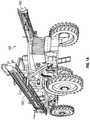
- FIG. 1Ais a perspective view of one example of an agricultural sprayer.
- FIG. 1Bis a schematic view of one example of an agricultural sprayer including a localized product injection system.
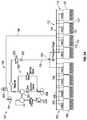
- FIG. 2Ais a schematic view of an agricultural sprayer including one example of a localized product injection system.
- FIG. 2Bis a detailed schematic view of one example of a localized injection interface in communication with a sprayer section of FIG. 2A .
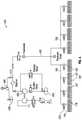
- FIG. 3Ais a schematic view of an agricultural sprayer including another example of a localized product injection system.
- FIG. 3Bis a detailed schematic view of another example of a localized injection interface in communication with a sprayer nozzle of FIG. 3A .
- FIG. 4is a schematic view of another example of an agricultural sprayer.
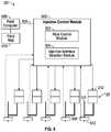
- FIG. 5is a schematic view of one example of an injection control module of a localized product injection system.
- FIG. 6is top view of one example of a field map including a plurality of zones indexed with concentration values for the injection product.
- FIG. 7is a block diagram showing one example of a method for using a localized product injection system.
- FIG. 1Ashows one example of a sprayer 100 .
- sprayer 100is a vehicle based sprayer including an agricultural product dispensing system carried by the vehicle.
- the sprayer 100includes, but is not limited to, a trailer housed sprayer configured for coupling with a vehicle, such as a tractor or the like.
- the sprayer 100includes at least two sprayer booms 102 .
- the sprayer booms 102 shown in FIG. 1Aare in a stowed configuration, for instance during transport of the sprayer 100 into a field.
- the sprayeris configured to apply one or more agricultural products including, but not limited to, fertilizers, herbicides, pesticides or the like.
- the sprayer 100applies the agricultural product in a liquid form, for instance through one or more nozzle assemblies positioned along the sprayer boom 102 according to the spacing of rows of agricultural crops.
- the sprayer 100applies the agricultural product by mixing an injection product with a carrier fluid to achieve a desired concentration of the injection product (a fertilizer, herbicide, pesticide or the like) within the carrier fluid.
- the injection productincludes a plurality of injection products, for instance injected separately by way of differing injection systems or injected as a common mixture of fluids (e.g., from a mixed injection reservoir) into the product dispensers including one or more of the boom sections and nozzle assemblies of the sprayer booms 102 .
- an agricultural productis provided in a localized manner to each of the product dispensers whether boom sections or nozzles to provide individualized control of application of the agricultural product.
- the instantaneous injection of the injection product to the carrier fluid stream prior locally to the product dispensersensures lag time between a desired change in concentration of the injection product and the corresponding application of the adjusted agricultural product is minimized (e.g., negligible lag time or allows for near instant injection and dispensing of the resulting agricultural product).
- other systemsmix the injection product upstream from the product dispensers, for instance within the carrier fluid reservoir or at an interchange near a header pump for the carrier fluid.
- a localized product injection systemas described herein provides a pressurized environment for the injection product at the one or more product dispensers (e.g., locally) for instance the boom sections, nozzles, nozzle assemblies or the like. Accordingly, the injection product is provided under pressure to the carrier fluid at the product dispensers immediately prior to application to an agricultural crop.
- the sprayer 100includes a carrier system 103 including a carrier reservoir 104 positioned centrally within the vehicle or tender.
- the carrier reservoir 104includes a carrier fluid therein, for instance water or the like.
- the carrier reservoir 104includes a carrier fluid such as water mixed with an initial carrier product (e.g., a mixed carrier formulation).
- the carrier fluidin such an example includes, but is not limited to, a primary fertilizer, a primary chemical or water base and fertilizer mixture, spray adjuvant, surfactant or the like.
- the carrier fluidis distributed from the carrier reservoir by way of a header 105 coupled with one or more boom tubes 106 .
- the boom tubes 106extend along the sprayer booms 102 as shown in FIG. 1B and corresponding transport the carrier fluid the length of the sprayer booms.
- the boom tubes 106are in communication with one or more corresponding boom sections 108 .
- the boom sections 108are positioned along the sprayer booms 102 and each provide a plurality of nozzle assemblies 110 .
- the product dispensers 107include, but are not limited to, one or more of the boom sections 108 , the nozzle assemblies 110 or a combination of both.
- Carrier fluidis accordingly distributed from the carrier reservoir 104 through the header 105 into the boom tubes 106 .
- the carrier fluidis then carried from the boom tubes 106 to one or more boom sections 108 and the associated nozzle assemblies 110 for application of the carrier fluid (mixed with the injection product as described herein) to the agricultural crops.
- the localized product injection system 112is also shown schematically in two different formats in FIG. 1B .
- the localized product injection system 112includes a product injection reservoir 114 separate from the carrier reservoir 104 .
- the product injection reservoir 114includes a volume of the injection product therein (concentrated fertilizer, herbicide, pesticide or the like).
- the product injection reservoir 114feeds into an injection header 116 which is in communication with one or more injection boom tubes 118 extending along the sprayer booms 102 .
- the injection boom tubes 118are coupled with the product dispensers 107 (the boom sections 108 ) by one or more injection interfaces 120 .
- the injection interfaces 120are provided at opposed ends of the boom section 108 .
- the injection interfaces 120are provided at a single or multiple locations along the boom section 108 .
- the injection productis distributed to the boom section 108 through the injection interfaces 120 .
- the injection interfaces 120include at least one control valve configured to vary the flow of the injection product into the product dispenser 107 (in this case the boom section 108 ) for mixing with the carrier fluid prior to application.
- the second format of the localized product injection system 112is also shown in the FIG. 1B schematic view.
- the injection interfaces 120are coupled with the nozzle assemblies 110 of one or more boom sections 108 .
- the injection interfaces 120are provided at each of the nozzle assemblies 110 .
- the injection interfaces 120provide individualized injection of the injection product to each of the nozzle assemblies 110 .
- the injection interfaces 120 at the nozzle assemblies 110provide individualized control of the concentration of the injection product at each of the nozzle assemblies 110 .
- the controlled injection of the injection product by the injection interfacesallows for individualized control of the product dispensers, including individualized control of one or more of the boom sections 108 or the nozzle assemblies 110 .
- the localized product injection system 112provides a pressurized environment for the injection product at the injection interfaces 120 (whether the injection interfaces are at the boom section 108 or nozzle assemblies 110 ). That is to say, the injection product is maintained at a pressure for immediate injection into the carrier fluid of the carrier system 103 at the local injection interfaces 120 immediately prior to application of the resulting agricultural product through the product dispensers 107 . Accordingly, there is no appreciable lag time between the injection of the injection product to the carrier fluid and application of the resulting agricultural product (including the carrier fluid and the injection product) to the agricultural crop.
- the injection productis immediately mixed with the carrier fluid to the desired concentration, for instance with a static mixer, by virtue of the jet of the injection product into the carrier fluid stream from the injection interfaces 120 or the like. Desired concentration of the injection product is achieved at the product dispensers 107 according to an individualized concentration determination (e.g., with an automated controller) for each corresponding injection interface 120 . Accordingly, the sprayer 100 shown in FIG. 1B including the localized product injection system 112 is able to individually control the content of the agricultural product (for instance the concentration of the injection product within the carrier fluid) at each of the injection interfaces 120 and the corresponding product dispensers 107 .
- the sprayer 100is thereby able to control the concentration of the injection product at each of the boom sections 108 .
- each of the injection interfaces 120are individually controlled to accordingly provide a desired concentration of the injection product at each of the nozzle assemblies 110 .
- the injected productis optionally used as a supplemental chemical with mixed carrier formulations for spot treatment in areas of the field where mixed carrier formulation is not sufficient to achieve the desired results (e.g., control of weeds, pests, or yield).
- an operatorapplies a primary herbicide (Monsanto brand Roundup®) from the carrier reservoir 104 .
- the herbicideis mixed with water and a spray adjuvant in the carrier reservoir 104 for general application to the field for corresponding general weed control.
- the operatoror field map
- the operatoris aware that the primary herbicide alone will not control certain weeds at certain areas of the field (e.g., because of resistance to the primary herbicide) and accordingly indexes locations for specified injections of the injection product.
- the operatoruses a supplemental herbicide as an injection product in the injection product reservoir 114 (such as DuPont brand Assure®) to control weeds in those areas in addition to the mixed carrier formulation.
- a supplemental herbicideas an injection product in the injection product reservoir 114 (such as DuPont brand Assure®) to control weeds in those areas in addition to the mixed carrier formulation.
- the sprayere.g., the corresponding one or more product dispensers 107
- the injection product including the supplemental herbicideis injected into the corresponding product dispensers 107 and the areas are sprayed with both primary and secondary herbicides.
- the product dispensersmove out of the designated areas (e.g., the injection product is no longer specified or specified at a differing concentration) the injection product is injected at a different concentration or shut off from injection to the carrier fluid.
- the injection productis provided from each of the injection interfaces 120 irrespective of the flow rate of the carrier fluid within the carrier system 103 (e.g., at high or low flow of the carrier fluid). For instance, in a low flow condition only a moderate or small amount of the agricultural product is applied to the agricultural crop corresponding to a low flow of the carrier fluid from carrier system 103 . Because of the low flow rate of the carrier fluid in other systems an upstream added injection product has significant residence time and corresponding lag time in the system prior to application at a desired concentration. Stated another way, the lag time already present between addition of the injection product to the carrier fluid at the upstream and its actual application through a product dispenser is increased because of the minimized flow of the carrier fluid.
- the localized product injection system 112provides an immediate or instantaneous injection of the injection product at the injection interfaces 120 to the product dispensers 107 immediately prior to the application of the resulting agricultural product.
- FIG. 2Ashows a detailed example of a sprayer 100 including the localized product injection system 112 .
- the localized product injection system 112is in the boom section format.
- the injection interfaces 120are coupled with one or more boom sections 108 along the sprayer booms 102 and boom tubes 106 shown in FIG. 1B .
- the carrier system 103is shown again in FIG. 2A and includes the carrier reservoir 104 .
- the carrier reservoir 104communicates with the product pump 201 that pressurizes the carrier fluid and delivers it within the header 105 (also shown in FIG. 2A ).
- the carrier system 103includes a carrier flow control valve 200 and a flow meter 202 .
- the flow meter 202cooperates with the carrier flow control valve 200 (e.g., with an intervening controller) to measure the output flow from the carrier reservoir 104 (produced by the product pump 201 ) and to facilitate actuating of the carrier flow control valve 200 to achieve the desired flow rate of carrier fluid to the plurality of boom sections 108 described herein.
- the header 105extends to the boom tubes 106 extending to the left and right of the header 105 .
- Each of the boom tubes 106in turn feeds into a plurality of boom sections 108 and the boom sections 108 each have corresponding nozzle assemblies 110 .
- section valves 205are interposed between each boom section 108 and the corresponding boom tubes 106 .
- the sections valves 205facilitate control of the carrier fluid flow to each of the boom sections 108 .
- the product dispensers 107include the boom sections 108 . That is to say, the injection interfaces 120 are coupled with the boom sections 108 and thereby provide individualized control of the injection product to each of the boom sections 108 relative to the other boom sections.
- the injection product reservoir 114communicates with an injection pump 203 .
- the injection pump 203delivers the injection fluid from the reservoir 114 to an injection header 116 .
- the injection header 116delivers the injection product to one or more injection boom tubes 118 extending to the left and right and shown in FIG. 2A .
- the injection boom tubes 118distribute the injection product to a plurality of injection interfaces 120 .
- the injection interfaces 120 in the example shown in FIG. 2Adeliver the injection product directly to each of the product dispensers 107 (e.g., the boom sections 108 ).
- the localized product injection system 112is isolated from the carrier system 103 until localized introduction of the injection product at the injection interfaces 120 . Accordingly, the localized product injection system 112 is able to maintain a pressurized environment for the injection product to the injection interfaces 120 (e.g., with the injection pump 203 ). At the injection interfaces 120 the pressurized injection product is delivered to each of the product dispensers 107 as determined, for instance, by a controller module described herein. Even in low flow situations with a low flow of carrier fluid, metered by the flow meter 202 and the carrier flow control valve 200 , the injection product is provided in a pressurized manner and is thereby ready for instantaneous delivery to one or more of the boom sections 108 .
- individualized and instantaneous control of the injection product(e.g., the concentration of the injection product) is achieved for each of the product dispensers 107 including the boom sections 108 .
- the injection productis provided from the injection interfaces 120 locally relative to the to boom sections and remote from the upstream carrier reservoir 104 .
- the boom section 108extends from left to right on the page and includes a plurality of nozzle assemblies 110 .
- the nozzle assemblies 110each include a nozzle check valve 222 and a corresponding nozzle 224 (e.g., an atomizer nozzle, stream nozzle or the like).
- nine nozzle assemblies 110are provided in a spaced configuration along the boom section 108 .
- Carrier lines 206introduce carrier fluid to each of boom section first and second ends 218 , 220 .
- each of the carrier lines 206includes a check valve 208 and a mixer 210 such as a static mixer.
- the localized product injection system 112 shown in FIG. 2Bincludes the injection interfaces 120 .
- an injection interface 120is associated with each of the carrier lines 206 (the carrier lines extending from the boom tube 106 of the carrier system 103 to the boom section 108 ).
- Each of the injection interfaces 120delivers injection product to the associated carrier line 206 in communication with the boom section first and second ends 218 , 220 .
- the injection interfaces 120include interface valves 212 in series with check valves 214 .
- the interface valves 212include pulse width modulation valves or other control valves configured to provide a metered flow of the pressurized injection product through the injection interfaces 120 to injection ports 216 in communication with each of the carrier lines 206 .
- the actuation of the interface valves 212for instance to a desired flow rate, delivers the designated amount of injection product to each of the corresponding carrier lines 206 at the injection ports 216 .
- the solution of the carrier fluid and the injection productis delivered through the mixers 210 and mixed prior to delivery to the boom section 108 .
- the mixed solution of the carrier fluid and the injection product(the agricultural product) is thereafter delivered from the boom section first and second ends 218 , 220 throughout the boom section 108 and to each of the nozzle assemblies 110 .
- each of the nozzle assemblies 110 associated with a particular boom section 108delivers substantially the same agricultural product having the same injection product concentration.
- the injection interfaces 120 associated with the boom section 108are operated independently relative to other injection interfaces 120 associated with other boom sections 108 of the sprayer 100 . Accordingly individualized control and instantaneous delivery of the injection product to each of the boom sections 108 is achieved for each of the boom sections 108 .
- FIG. 3Ashows another example of the sprayer 100 .
- the example shown in FIG. 3Ais similar in at least some regards to the sprayer 100 previously shown and described in FIGS. 2A and 2B .
- the sprayer 100 shown in FIGS. 3A and 3Bincludes an isolated localized product injection system 112 that is separate from the corresponding carrier system 103 .
- the localized product injection system 112delivers an injection product from the injection product reservoir 114 to a plurality of boom sections 108 .
- the injection interfaces 120are each in communication with corresponding nozzle assemblies 110 . Stated another way, the product dispensers 107 in the example shown in FIGS.
- 3A and 3Bare the nozzle assemblies 110 . Accordingly individualized control and instantaneous injection of the injection product are provided at each of the nozzle assemblies 110 .
- Each of the injection interfaces 120are independently controlled according to determined concentrations of the injection product within the carrier fluid. The dispensed agricultural product from each of the nozzle assemblies thereby has a varying concentration of the injection product based on the independent control of the concentration provided by the injection interfaces 120 .
- the injection interface 120includes an interface valve 212 and a check valve 214 similar in at least some regards to the interface valve and check valves previously described and shown in FIG. 2B .
- the injection interface 120 in this exampleincludes an injection port 308 provided at the nozzle assembly 110 and downstream from a carrier line 300 communicating with the boom section 108 or boom tube 106 .
- the nozzle assembly 110includes a check valve 302 and an in-line mixer 304 (e.g., a static mixer).
- the nozzle assembly 110further includes a nozzle 306 , such as an atomizer or stream nozzle in communication with the mixer 304 .
- the injection port 308is coupled with the nozzle assembly 110 , for instance the injection port is interposed between the check valve 302 and the mixer 304 .
- the injection productis delivered through the injection boom tubes 118 to each of the injection interfaces 120 .
- the interface valve 212meters the amount of injection product delivered to the corresponding nozzle assembly 110 .
- the injection productis independently metered for each of the injection interfaces 120 according to control signals from a controller associated with each of the injection interfaces 120 .
- the controlleris configured to control each of the injection interfaces independently or in one or more groups or arrays.
- the injection productis delivered from the interface valve 212 through the check valve 214 and into the nozzle assembly 110 through the injection port 308 .
- the injection product in combination with the carrier fluidis optionally mixed within the mixer 304 and thereafter delivered through the nozzle 306 as the agricultural product having the specified concentration of the injection product.
- the localized product injection system 112 shown in FIGS. 3A and 3Bis configured to provide an instantaneous addition of an injection product to the carrier fluid stream immediately prior to its dispensing through the nozzle 306 (e.g., local to the product dispenser 107 ). Accordingly, instantaneous changes in concentration of the injection product in an agricultural product, for instance for differing parts of a field, are achieved on an instantaneous as-needed basis as the sprayer 100 moves through the field.
- FIG. 4shows another example of a sprayer 400 .
- the sprayer 400 shown in FIG. 4includes a consolidated system having the product injection reservoir 406 and the injection pump 408 feeding into an injection port 410 of a header 412 of the sprayer 400 .
- the carrier fluidis pumped from a carrier reservoir 402 by a carrier pump 404 and supplemented with the injection product at the injection port 410 (e.g., by the injection pump 408 ).
- a mixeris provided downstream from the injection port 410 for mixing the injection product with the carrier fluid prior to delivery through the header 412 to the boom tubes 406 , the boom sections 108 and the nozzle assemblies 110 .
- the injection productis provided to the flow of carrier fluid upstream from the nozzle assemblies 110 and the boom sections 108 . Accordingly, there is significant lag time from the time of introduction of the injection product to the carrier fluid and eventual distribution of the agricultural product including the injection product therein from the nozzle assemblies 110 . Additionally, beyond the lag time each of the nozzle assemblies 110 and the boom sections 108 (the product dispensers 107 ) delivers an identical concentration of the injection product within the agricultural product across the sprayer 400 . Accordingly, the sprayer 400 does not provide independent control or instantaneous introduction of the injection product to the product dispensers 107 .
- FIG. 5shows one example of a control system 501 for the sprayer 100 .
- the control system 501controls a plurality of injection interfaces 120 (five interfaces are shown for exemplary purposes) associated with the nozzle assemblies 110 previously described herein.
- the control system 501is also configured for coupling the injection interfaces 120 associated with either of the nozzle assemblies 110 (as shown in FIG. 3B ) as well as the boom sections 108 (shown in FIG. 2B ). Stated another way, the control system 501 is used with injection interfaces 120 associated with any of the product dispensers 107 .
- the control system 501includes an injection control module 500 .
- the injection control module 500is in communication with each of the injection interfaces 120 , for instance by one or more of wired or wireless connections or the like.
- the injection control module 500includes, in one example, a rate control module 502 configured to determine and generate signals for one or more of the injection interfaces 120 corresponding to independent injection flow rates.
- the flow ratescorrespond to injection product concentrations for a given flow rate of carrier fluid.
- the injection control module 500includes an injection interface selection module 504 .
- the injection interface selection module 504designates one or more of the injection interfaces 120 for adjustment of the injection flow rate of injection product (e.g., on, off, and graduated flow rates of the injection product).
- the injection interface selection module 504selects one or more of the injection interfaces 120 for individualized control of the injection interfaces 120 to achieve a desired concentration (e.g., change in concentration) of the injection product in the carrier fluid.
- the rate control module 502determines the corresponding rate for each of these selected injection interfaces 120 , for instance in cooperation with the field computer interface 506 and a field computer 508 as described herein.
- the injection interfaces 120each include an interface valve 212 in communication with the injection control module 500 as previously described herein.
- the interface valve 212accordingly allows for a controlled graduated flow of the injection product through the injection port 308 and into the corresponding product dispenser 107 .
- the injection port 308is identical to the injection port 308 previously described and shown in FIG. 3B .
- the injection port 216is used with the injection interface 120 , for instance in a format corresponding to the example shown in FIGS. 2A and 2B , for the product dispenser 107 including the boom section 108 .
- an optional concentration sensor 512is downstream from the injection port 308 .
- the concentration sensor 512includes a relative concentration sensor configured to detect the concentration of the injection product within the agricultural product based on a comparison of at least one characteristic of the agricultural product at a product dispenser 107 relative to the same at least one characteristic at another product dispenser 107 .
- the concentration sensor 512includes a sensor configured to measure one or more characteristics of the injection product (e.g., colors, translucency, or the like corresponding to concentration) relative to a look up table or other database.
- the concentration sensor 512includes an ultraviolet light sensor that assesses concentration based on color.
- a detectable tracer dyeis added into the injection reservoir 114 shown in FIGS. 2A and 3A .
- the concentration sensor 512is configured to measure the concentration of the tracer dye within the agricultural product and is thereby able to associate the measured concentration of the tracer dye with the corresponding concentration of the injection product.
- the concentration sensor 512includes, but is not limited to, a pH detector configured to measure the alkalinity or acidity of the injection product within the agricultural product prior to dispensing through one or more of the product dispensers 107 including the boom sections 108 or nozzle assemblies 110 .
- the concentration sensors 512are in communication with the injection control module 500 .
- the concentration sensors 512cooperate with the injection control module 500 to provide for feedback control of the interface valves 212 of each of the injection interfaces 120 .
- the corresponding concentration sensors 512 for those injection interfaces 120measure the concentration in an ongoing manner and accordingly allow for adjustments of the interface valves 212 to accordingly ensure the interface valve 212 is actuated to administer the appropriate concentration of the injection product to the carrier fluid.
- the agricultural product dispensed from each of the product dispensers 107has the concentration of the injection product determined by the injection control module 500 despite variations in the localized product injection system 112 , in the carrier system 103 or the like.
- the injection control module 500includes a field computer interface 506 .
- the field computer interface 506provides an interface for coupling with a field computer 508 (part of the sprayer 100 , with a leading vehicle such as a tractor, or a standalone device) and the field computer 508 includes a field map 510 .
- the field map 510includes a series of prescriptions of agricultural products, seed types, irrigation or the like for various zones. The differing prescriptions for each of the zones are determined through analysis of the field terrain, yields from previous crops, environmental conditions or the like.
- the field map 510provides a plurality of prescriptions for an agricultural product or agricultural products throughout the field (e.g., in one or more of the zones of the field). As the field computer 508 communicates with the injection control module 500 the injection control module uses the field map 510 and its associated zone based prescriptions to independently specify the flow rate of an injection product for each of the injection interfaces 120 for corresponding product dispensers 107 .
- the injection control module 500selects the corresponding injection interfaces 120 for adjustment of the injection product concentration based on the field map prescription.
- the injection product concentrationis changed instantaneously at the product dispensers 107 (e.g., with minimal lag time) relative to the application of the resulting agricultural product according to the prescription.
- the rate control module 502assesses the corresponding injection product concentration and actuates the interface valves 212 of the injection interfaces 120 associated with the one or more corresponding product dispensers 107 .
- the interface valves 212are operated (opened, closed or graduated therebetween) to achieve the flow rate of the injection product that results in the specified concentration for that portion of the field map.
- the injection productis thereby introduced in an instantaneous manner at the product dispensers 107 (e.g., locally to the dispensers) immediately prior to dispensing of the agricultural product having the desired concentration to that corresponding portion of the field.
- the sprayer 100 described hereinis able to instantaneously deliver an accurate concentration of the injection product to the carrier system at one or more of the injection interfaces 120 by way of individualized control of each of those injection interfaces 120 . Accordingly, with the field map 510 having various prescriptions and a plurality of product dispensers 107 with individually controlled injection interfaces 120 a multitude of injection product concentrations are provided across the sprayer 102 to accordingly provide the agricultural product with varying concentrations of the injection product to a corresponding variety of different parts of the field.
- FIG. 6shows one example of a field 601 including at least one subdivision such as a field section 603 .
- the field section 603is enlarged in the detailed view provided immediately below the field 601 .
- the field sectionis divided into a plurality of zones 602 .
- Two exemplary zones 604 , 606are provided.
- each of the zones 604 , 606has a corresponding stippling, crosshatching or the like denoting a particular concentration of an injection product for an agricultural product (e.g., for a fungicide, herbicide, pesticide, fertilizer or the like).
- the zones 602 of the field 601are indexed to a field map 600 .
- the field map 600 including the zones 602provides a consolidated series of prescriptions for application of the agricultural product with varying concentrations of an injection product therein.
- the field map 600is accessed by the field computer 508 and the injection control module 500 .
- the injection control module 500accesses the field map 600 directly.
- the injection control moduleuses the prescription for the agricultural product for that zone to control the concentration of the injection product for the corresponding product dispensers 107 .
- the injection control module 500e.g., the injection interface selection module 504 selects the relevant injection interfaces 120 corresponding to the product dispensers 107 .
- the rate control module 502uses the prescriptions provided in the field map 510 (e.g., zones 604 , 606 ) to accordingly signal the interface valves 212 with the flow rates of the injection product corresponding to the specified concentration of the injection product.
- the injection productis then instantaneously delivered to the carrier fluid flow at the product dispensers 107 to ensure timely delivery of the injection product into the carrier system for corresponding delivery of the agricultural product (with the specified concentration of injection product) to the instant zone 602 of the field 601 .
- the sprayer 100 described hereinincluding for instance the localized product injection system 112 (described in examples shown in FIGS. 2A through 3B ), is configured to provide instantaneous individualized control of injection product concentration at each of a plurality of product dispensers 107 .
- the injection productis immediately and locally distributed to the respective product dispensers 107 immediately prior to the desired application of the agricultural product.
- the localized product injection system 112is isolated from the carrier system 103 , excepting the injection ports 216 , 308 (see FIGS. 2B, 3B ), even in low flow conditions of the carrier fluid through the carrier system 103 the injection product is still delivered at pressure and with the desired independently controlled concentrations to the corresponding product dispensers 107 . Lag time that would otherwise delay the introduction of the injection product with the desired concentration is accordingly mitigated or eliminated even in low flow conditions because of the immediate introduction at the product dispensers 107 .
- FIG. 7shows one example of a method 700 for using a localized product injection system, such as the system 112 described herein.
- a localized product injection systemsuch as the system 112 described herein.
- reference numeralsprovided are exemplary and are not exclusive.
- the features, components, functions and the like described in the method 700include but are not limited to the corresponding numbered elements, other corresponding features described herein, both numbered and unnumbered as well as their equivalents.
- the method 700includes pressurizing an injection product within a localized product injection system 112 .
- the localized product injection system 112includes one or more localized injection interfaces 120 and corresponding product dispensers 107 .
- the product dispensers 107include, but are not limited to, boom sections 108 .
- the product dispensers 107include, but are not limited to, nozzle assemblies, such as the nozzle assemblies 110 shown for instance in FIGS. 3A and 3B .
- a specified injection concentrationis determined for one or more of the product dispensers 107 .
- determining the specified injection concentration for the one or more product dispensers 107includes determining an injection concentration for the corresponding injection interfaces 120 associated with those product dispensers 107 .
- the one or more product dispensers 107pass through a plurality of zones such as the zones 604 , 606 of a field map 600 .
- the field map 600 and one or more of GPS positioning, mathematical algorithms, combinations of the same, or the likeare assessed by an injection control module 500 to determine the locations of the corresponding product dispensers 107 relative to the zones 602 . Concentrations of the injection product are indexed to each of the zones 602 .
- the corresponding concentrationsare associated with the product dispensers and the respective injection interfaces by the injection control module 500 .
- the method 700includes operating one or more interface valves 212 of the injection interfaces 120 for the corresponding one or more product dispensers 107 .
- Operating of the one or more interface valves 120includes, at 708 , injecting the injection product to a carrier fluid of a carrier system 103 at the one or more product dispensers 107 (e.g., at the boom sections 108 or nozzle assemblies 110 ).
- Operating the one or more interface valves 120includes, at 710 , instantaneously (e.g., near instantaneously or instantaneously) changing the injection concentration in the carrier flow to the specified injection concentration at the one or more product dispensers 107 .
- the injecting and instantaneous change of the injection concentrationoccurs according to the positioning of the one or more interface valves 212 (of the injection interfaces 120 ) and the corresponding injection ports ( 216 , 308 ) at the one or more product dispensers 107 . Stated another way, by positioning the injection interfaces 120 at the product dispensers 107 the concentration of the injection product in the agricultural product is immediately changed prior to dispensing the resulting agricultural product from the sprayer 102 .
- the injection control module 500independently controls the one or more injection interfaces as described herein. With the concentrations of the injection product associated with the one or more injection interfaces 120 (e.g., through use of a field map 600 having a plurality of zones 602 ), the injection control module 500 actuates the interface valves 212 of the corresponding injection interfaces 120 to independently provide flow of the injection product to the product dispensers 107 as prescribed.
- pressurizing the injection productincludes pressurizing the injection product to each of the one or more localized injection interfaces 120 positioned at the one or more product dispensers 107 .
- the localized product injection system 112is isolated from the carrier system 103 and interfaces with the carrier system at the injection interfaces 120 (local to the product dispensers 107 ).
- the injection productis instantaneously injected into the carrier flow at the product dispensers 107 .
- the pressurized system 112separate from the carrier system 103 ensures the injection product is instantaneously delivered to the carrier fluid to accordingly provide agricultural product at the one or more product dispensers 107 having the desired concentration of the injection product with little to no lag time between injection and application.
- the injection interfaces 120 at the product dispensers 107(as opposed to upstream near the carrier reservoir 104 ) the agricultural product having the specified injection concentration is immediately applied through the product dispensers 107 , for instance the boom sections 108 and the nozzle assemblies 110 .
- lag time otherwise present with upstream mixing of the injection product into a flow of the carrier fluidis avoided.
- the instantaneous injection and corresponding instantaneous change in concentration of the injection product within the carrier fluidgenerates an agricultural product having the desired injection concentration immediately prior to its application to the agricultural crop.
- the method 700includes measuring the injection concentration in the agricultural product (carrier fluid) at the one or more product dispensers 107 .
- the product dispensers 107include corresponding concentration sensors 512 (see FIG. 5 ).
- a flow rate of the injection productis changed or controlled according to the measured injection concentration and the specified injection concentration.
- the concentration sensor 512communicates with the injection control module 500 to provide feedback control to accordingly tune the concentration to achieve the specified injection concentration specified by the rate control module 502 .
- operating the one or more interface valves 212includes individually operating the one or more interface valves 212 (e.g., independently or as arrays). For instance, as described herein and shown for instance in FIGS. 5, 2B and 3B the injection interfaces 120 are independently operable relative to the other injection interfaces 120 of the sprayer 100 . Accordingly, the localized product injection system 112 provides varying flow rates of the injection product to each of the product dispensers 107 according to individualized specified concentrations. In one example, the individualized specified concentrations are provided by the injection control module 500 configured to assess and determine injection product concentrations from a field map 510 having one or more varying prescriptions for the agricultural product.
- Example 1can include subject matter such as can include a localized product injection system for use with a product dispensing system, the localized product injection system comprising: a product injection reservoir including an injection product; an injection header coupled with the product injection reservoir; one or more injection boom tubes coupled with the injection header; and a plurality of localized injection interfaces each configured for coupling at a corresponding product dispenser of a plurality of product dispensers, the plurality of localized injection interfaces in communication with the one or more injection boom tubes, each of the plurality of localized injection interfaces includes: an interface valve, an injection port in communication with the interface valve, the injection port configured for localized coupling and injection to the corresponding product dispenser, and wherein the plurality of localized injection interfaces are remote from the product injection reservoir and at the plurality of product dispensers.
- a localized product injection systemfor use with a product dispensing system
- the localized product injection systemcomprising: a product injection reservoir including an injection product; an injection header coupled with the product injection reservoir; one or more injection boom tubes coupled with
- Example 2can include, or can optionally be combined with the subject matter of Example 1, to optionally include an injection control module, the injection control module operates each of the interface valves of the plurality of localized injection interfaces.
- Example 3can include, or can optionally be combined with the subject matter of one or any combination of Examples 1 or 2 to optionally include wherein the injection control module independently operates one or more of the interface valves of the plurality of localized injection interfaces.
- Example 4can include, or can optionally be combined with the subject matter of one or any combination of Examples 1-3 to optionally include wherein the interface valve includes a control valve configured to control an injection flow rate of the injection product to the corresponding product dispenser.
- the interface valveincludes a control valve configured to control an injection flow rate of the injection product to the corresponding product dispenser.
- Example 5can include, or can optionally be combined with the subject matter of one or any combination of Examples 1-4 optionally to include wherein the corresponding product dispenser includes a boom section, and the injection port of one or more of the plurality of localized injection interfaces is configured for coupling with the boom section.
- Example 6can include, or can optionally be combined with the subject matter of Examples 1-5 to optionally include wherein the corresponding product dispenser includes a boom section, and two or more injection ports of the plurality of localized injection interfaces are configured for coupling with opposed ends of the boom section.
- Example 7can include, or can optionally be combined with the subject matter of Examples 1-6 to optionally include wherein the corresponding product dispenser includes a nozzle assembly, and the injection port of one or more of the plurality of localized injection interfaces is configured for coupling with the nozzle assembly, the nozzle assembly in communication with a boom section.
- Example 8can include, or can optionally be combined with the subject matter of Examples 1-7 to optionally include wherein the corresponding product dispenser includes one or more of a boom section or a nozzle assembly.
- Example 9can include, or can optionally be combined with the subject matter of Examples 1-8 to optionally include wherein the interface valve is adjacent to the injection port, the interface valve controls the injection of the injection product to the corresponding product dispenser.
- Example 10can include, or can optionally be combined with the subject matter of Examples 1-9 to optionally include wherein the injection port includes an atomizer configured to mix the injection product into a carrier flow in the corresponding product dispenser.
- Example 11can include, or can optionally be combined with the subject matter of Examples 1-10 to optionally include wherein the injection port is configured for coupling with the corresponding product dispenser upstream from a mixing device.
- Example 12can include, or can optionally be combined with the subject matter of Examples 1-11 to optionally include an injection pump coupled with the production injection reservoir and the injection header, the injection pump configured to pressurize the injection product within the one or more injection boom tubes from the pump to the plurality of localized injection interfaces at the plurality of product dispensers.
- an injection pumpcoupled with the production injection reservoir and the injection header, the injection pump configured to pressurize the injection product within the one or more injection boom tubes from the pump to the plurality of localized injection interfaces at the plurality of product dispensers.
- Example 13can include, or can optionally be combined with the subject matter of Examples 1-12 to optionally include a carrier system including: a carrier product reservoir including a carrier product, a header coupled with the carrier product reservoir, one or more boom tubes, and a plurality of product dispensers; and wherein the injection product is pressurized and isolated from the carrier product reservoir, the header and the one or more boom tubes, and the injection product is selectively introduced to the plurality of product dispensers with the plurality of localized injection interfaces at the plurality product dispensers.
- a carrier systemincluding: a carrier product reservoir including a carrier product, a header coupled with the carrier product reservoir, one or more boom tubes, and a plurality of product dispensers; and wherein the injection product is pressurized and isolated from the carrier product reservoir, the header and the one or more boom tubes, and the injection product is selectively introduced to the plurality of product dispensers with the plurality of localized injection interfaces at the plurality product dispensers.
- Example 14can include, or can optionally be combined with the subject matter of Examples 1-13 to optionally include a localized product injection system comprising: one or more injection boom tubes; a plurality of localized injection interfaces coupled with the one or more injection boom tubes, the plurality of localized injection interfaces configured for coupling with a plurality of product dispensers, each of the injection interfaces includes: an interface valve, an injection port in communication with the interface valve, the injection port configured for communication with a corresponding product dispenser of the plurality of product dispensers, and wherein the interface valve and the injection port are configured for positioning at the product dispenser; and wherein the plurality of localized injection interfaces maintain a controlled pressurized environment of an injection product through the localized product injection system to the plurality of product dispensers.
- a localized product injection systemcomprising: one or more injection boom tubes; a plurality of localized injection interfaces coupled with the one or more injection boom tubes, the plurality of localized injection interfaces configured for coupling with a plurality of product dispensers, each of the injection interfaces
- Example 15can include, or can optionally be combined with the subject matter of Examples 1-14 to optionally include wherein the interface valve and the injection port of each of the plurality of localized injection interfaces are immediately adjacent to each other.
- Example 16can include, or can optionally be combined with the subject matter of Examples 1-15 to optionally include wherein the interface valve and the injection port of each of the plurality of localized injection interfaces are immediately adjacent to the corresponding product dispensers of the plurality of product dispensers.
- Example 17can include, or can optionally be combined with the subject matter of Examples 1-16 to optionally include an injection control module in communication with the interface valve of each of the plurality of localized injection interfaces, the injection module operates one or more of the interface valves to control the localized injection of the injection product at one or more product dispensers of the plurality of product dispensers.
- an injection control modulein communication with the interface valve of each of the plurality of localized injection interfaces, the injection module operates one or more of the interface valves to control the localized injection of the injection product at one or more product dispensers of the plurality of product dispensers.
- Example 18can include, or can optionally be combined with the subject matter of Examples 1-17 to optionally include wherein operation of the one or more interface valves with the injection control module instantaneously injects the injection product into the one or more product dispensers according to the interface valve and the injection port configured for positioning at the product dispenser.
- Example 19can include, or can optionally be combined with the subject matter of Examples 1-18 to optionally include wherein the injection control module includes a rate module, the rate module controls a rate of injection of the injection product at the one or more product dispensers of the plurality of product dispensers.
- the injection control moduleincludes a rate module, the rate module controls a rate of injection of the injection product at the one or more product dispensers of the plurality of product dispensers.
- Example 20can include, or can optionally be combined with the subject matter of Examples 1-19 to optionally include concentration sensors in communication with the injection control module, the concentration sensors configured for coupling with each of the plurality of product dispensers downstream from the respective injection ports of the plurality of localized injection interfaces.
- Example 21can include, or can optionally be combined with the subject matter of Examples 1-20 to optionally include wherein the injection control module operates the one or more interface valves according to injection product concentrations measured by the concentration sensors associated with the respective one or more interface valves.
- Example 22can include, or can optionally be combined with the subject matter of Examples 1-21 to optionally include wherein the injection control module individually controls operation of the interface valves of the plurality of localized injection interfaces.
- Example 23can include, or can optionally be combined with the subject matter of Examples 1-22 to optionally include wherein the injection control module includes an injection interface selection module, the injection interface section module selects one or more localized injection interfaces of the plurality of localized injection interfaces for operation of the respective interface valves.
- the injection control moduleincludes an injection interface selection module, the injection interface section module selects one or more localized injection interfaces of the plurality of localized injection interfaces for operation of the respective interface valves.
- Example 24can include, or can optionally be combined with the subject matter of Examples 1-23 to optionally include wherein the injection control module includes a field computer interface configured to couple with a field computer, the field computer determines the locations of one or more of the plurality of product dispensers on a field map, and the injection interface selection module selects the one or more localized injection interfaces according to the determined locations, and a rate module of the injection control module controls a rate of injection of the injection product at the one or more selected localized injection interfaces according to the determined locations.
- the injection control moduleincludes a field computer interface configured to couple with a field computer, the field computer determines the locations of one or more of the plurality of product dispensers on a field map, and the injection interface selection module selects the one or more localized injection interfaces according to the determined locations, and a rate module of the injection control module controls a rate of injection of the injection product at the one or more selected localized injection interfaces according to the determined locations.
- Example 25can include, or can optionally be combined with the subject matter of Examples 1-24 to optionally include a method for using a localized product injection system comprising: pressurizing an injection product within the localized product injection system, the injection product pressurized at least at one or more localized injection interfaces positioned at corresponding product dispensers of one or more product dispensers; determining a specified injection concentration for the one or more product dispensers; and operating one or more interface valves of the one or more localized injection interfaces for the one or more product dispensers, operating including: injecting the injection product to a carrier flow at the one or more product dispensers according to the pressurizing at the one or more localized injection interfaces, instantaneously changing an injection concentration in the carrier flow to the specified injection concentration at the one or more product dispensers according to the injecting, and wherein injecting and instantaneously changing the injection concentration occurs according to the positioning of the one or more interface valves and injection ports of the one or more localized injection interfaces at the one or more product dispensers.
- Example 26can include, or can optionally be combined with the subject matter of Examples 1-25 to optionally include wherein pressurizing the injection product includes pressurizing the injection product to each of the one or more localized injection interfaces positioned at the one or more product dispensers.
- Example 27can include, or can optionally be combined with the subject matter of Examples 1-26 to optionally include dispensing the carrier flow with the specified injection concentration from the one or more product dispensers immediately after injection and instantaneous change of the injection concentration.
- Example 28can include, or can optionally be combined with the subject matter of Examples 1-27 to optionally include measuring the injection concentration in the carrier flow at the one or more product dispensers; and controlling a rate of injection of the injection product according to the measured injection concentration and the specified injection concentration.
- Example 29can include, or can optionally be combined with the subject matter of Examples 1-28 to optionally include wherein operating one or more interface valves includes individually operating the one or more interface valves.
- Example 30can include, or can optionally be combined with the subject matter of Examples 1-29 to optionally include determining locations of each of the one or more product dispensers on a field map.
- Example 31can include, or can optionally be combined with the subject matter of Examples 1-30 to optionally include wherein determining the specified injection concentration for one or more product dispensers includes determining the specified injection concentration according to the injection concentrations associated with the determined locations on the field map; and operating the one or more interface valves includes operating the one or more interface valves according to the determined locations and the associated injection concentrations.
- Example 32can include, or can optionally be combined with the subject matter of Examples 1-31 to optionally include wherein operating the one or more interface valves includes selecting the one or more interface valves for operation based on the determined locations of the one or more product dispensers.
- Example 33can include, or can optionally be combined with the subject matter of Examples 1-32 to optionally include wherein the one or more product dispensers include one or more nozzle assemblies.
- Example 34can include, or can optionally be combined with the subject matter of Examples 1-33 to optionally include wherein the one or more product dispensers include one or more boom sections.
- Example 35can include, or can optionally be combined with the subject matter of Examples 1-34 to optionally include wherein one or more of injecting or instantaneously changing the injection concentration includes mixing the injection product with the carrier flow at the one or more product dispensers.
- the terms “a” or “an”are used, as is common in patent documents, to include one or more than one, independent of any other instances or usages of “at least one” or “one or more.”
- the term “or”is used to refer to a nonexclusive or, such that “A or B” includes “A but not B,” “B but not A,” and “A and B,” unless otherwise indicated.
- Method examples described hereincan be machine or computer-implemented at least in part. Some examples can include a computer-readable medium or machine-readable medium encoded with instructions operable to configure an electronic device to perform methods as described in the above examples.
- An implementation of such methodscan include code, such as microcode, assembly language code, a higher-level language code, or the like. Such code can include computer readable instructions for performing various methods. The code may form portions of computer program products. Further, in an example, the code can be tangibly stored on one or more volatile, non-transitory, or non-volatile tangible computer-readable media, such as during execution or at other times.
- Examples of these tangible computer-readable mediacan include, but are not limited to, hard disks, removable magnetic disks, removable optical disks (e.g., compact disks and digital video disks), magnetic cassettes, memory cards or sticks, random access memories (RAMs), read only memories (ROMs), and the like.
Landscapes
- Life Sciences & Earth Sciences (AREA)
- Engineering & Computer Science (AREA)
- Environmental Sciences (AREA)
- Insects & Arthropods (AREA)
- Pest Control & Pesticides (AREA)
- Wood Science & Technology (AREA)
- Zoology (AREA)
- Water Supply & Treatment (AREA)
- Soil Sciences (AREA)
- Catching Or Destruction (AREA)
Abstract
Description
Claims (37)
Priority Applications (2)
| Application Number | Priority Date | Filing Date | Title |
|---|---|---|---|
| US14/300,761US11160204B2 (en) | 2013-03-15 | 2014-06-10 | Localized product injection system for an agricultural sprayer |
| US17/504,601US20220104427A1 (en) | 2013-06-10 | 2021-10-19 | Localized product injection system for an agricultural sprayer |
Applications Claiming Priority (5)
| Application Number | Priority Date | Filing Date | Title |
|---|---|---|---|
| US13/832,678US9504212B2 (en) | 2013-03-15 | 2013-03-15 | Real time injection for agricultural sprayers |
| US13/832,735US20140263708A1 (en) | 2013-03-15 | 2013-03-15 | Multi-section applicator with variable-rate sections |
| US201361803942P | 2013-03-21 | 2013-03-21 | |
| US201361833290P | 2013-06-10 | 2013-06-10 | |
| US14/300,761US11160204B2 (en) | 2013-03-15 | 2014-06-10 | Localized product injection system for an agricultural sprayer |
Related Child Applications (1)
| Application Number | Title | Priority Date | Filing Date |
|---|---|---|---|
| US17/504,601ContinuationUS20220104427A1 (en) | 2013-06-10 | 2021-10-19 | Localized product injection system for an agricultural sprayer |
Publications (2)
| Publication Number | Publication Date |
|---|---|
| US20140361094A1 US20140361094A1 (en) | 2014-12-11 |
| US11160204B2true US11160204B2 (en) | 2021-11-02 |
Family
ID=52004631
Family Applications (1)
| Application Number | Title | Priority Date | Filing Date |
|---|---|---|---|
| US14/300,761Active2034-10-15US11160204B2 (en) | 2013-03-15 | 2014-06-10 | Localized product injection system for an agricultural sprayer |
Country Status (1)
| Country | Link |
|---|---|
| US (1) | US11160204B2 (en) |
Cited By (10)
| Publication number | Priority date | Publication date | Assignee | Title |
|---|---|---|---|---|
| US20200221682A1 (en)* | 2019-01-10 | 2020-07-16 | Capstan Ag Systems, Inc. | Systems and methods for fluid application including sectioned spray boom and section control valves for sectional pressure control |
| US20220062939A1 (en)* | 2020-08-26 | 2022-03-03 | Deere & Company | Work vehicle sprayer system and method with self-cleaning filter apparatus |
| US11759805B2 (en) | 2017-11-10 | 2023-09-19 | Amazonen-Werke H. Dreyer SE & Co. KG | Active substance supply system for an agricultural sprayer |
| US20230405499A1 (en)* | 2019-11-27 | 2023-12-21 | Agco Corporation | Sprayer filtering system |
| US11944030B2 (en) | 2012-06-18 | 2024-04-02 | Raven Industries, Inc. | Implement for adjustably metering an agricultural field input according to different frame sections |
| US20240196878A1 (en)* | 2021-04-08 | 2024-06-20 | Amazonen-Werke H. Dreyer SE & Co. KG | Method for Spreading Spraying Liquid onto Arable Agricultural Land |
| US12016326B2 (en) | 2017-01-05 | 2024-06-25 | Raven Industries, Inc. | Localized product injection system and methods for same |
| US12083543B2 (en) | 2020-08-26 | 2024-09-10 | Deere & Company | Work vehicle sprayer system and method with switching nozzle apparatus |
| US12330179B2 (en) | 2020-08-26 | 2025-06-17 | Deere &Company | Work vehicle sprayer system and method with pinching nozzle apparatus |
| US12403494B2 (en) | 2020-08-26 | 2025-09-02 | Deere & Company | Work vehicle sprayer system and method with nozzle monitoring |
Families Citing this family (17)
| Publication number | Priority date | Publication date | Assignee | Title |
|---|---|---|---|---|
| US10173236B2 (en) | 2013-10-17 | 2019-01-08 | Raven Industries, Inc. | Nozzle control system and method |
| US9781916B2 (en) | 2013-10-17 | 2017-10-10 | Raven Industries, Inc. | Nozzle control system and method |
| US9737067B2 (en)* | 2015-04-29 | 2017-08-22 | Memes Associates, Ltd. | Autonomous spraying platform |
| CN105766556B (en)* | 2016-02-23 | 2019-02-05 | 江苏大学 | A light and small precision irrigation sprinkler detachable frame |
| WO2017190698A1 (en)* | 2016-05-05 | 2017-11-09 | 东风农业装备(襄阳)有限公司 | Electric plant-protection machine and application thereof |
| DE102016112729A1 (en)* | 2016-07-12 | 2018-01-18 | Amazonen-Werke H. Dreyer Gmbh & Co. Kg | Spraying device and method for operating an injection device |
| US10159177B2 (en) | 2016-08-11 | 2018-12-25 | Cnh Industrial Canada, Ltd. | Flow control system for an agricultural product application system |
| EP3582602B1 (en) | 2017-02-16 | 2022-04-20 | Precision Planting LLC | Method of calibrating a pump output |
| US10653128B2 (en)* | 2017-08-23 | 2020-05-19 | Cnh Industrial America Llc | Spray system for a self-propelled agricultural machine having adjustable tread width and rear wheel nozzles |
| US20190183038A1 (en)* | 2017-12-15 | 2019-06-20 | Cnh Industrial Canada, Ltd. | System for controlling product treatment flow through distribution lines |
| DE102018102586A1 (en)* | 2018-02-06 | 2019-08-08 | Amazonen-Werke H. Dreyer Gmbh & Co. Kg | Method for dispensing a spray liquid |
| CA3040523C (en)* | 2018-04-18 | 2020-04-14 | Agrome Inc. | Robotic agricultural irrigation and analysis system |
| US11125681B2 (en) | 2019-01-24 | 2021-09-21 | Raven Industries, Inc. | Agricultural spectrographic composition sensor and methods for same |
| US11406096B2 (en)* | 2019-06-13 | 2022-08-09 | Cnh Industrial America Llc | Sprayer boom charging system |
| EP4041461A4 (en) | 2019-10-04 | 2023-11-01 | Raven Industries, Inc. | Valve control system and method |
| US11612160B2 (en) | 2019-10-04 | 2023-03-28 | Raven Industries, Inc. | Valve control system and method |
| US20210105934A1 (en)* | 2019-10-11 | 2021-04-15 | Seth Inman | Mobile Aqueous Chemical Injection And Application Apparatus |
Citations (221)
| Publication number | Priority date | Publication date | Assignee | Title |
|---|---|---|---|---|
| US1582986A (en) | 1924-04-09 | 1926-05-04 | Reyrolle A & Co Ltd | Alternating-current electromagnet |
| GB990346A (en) | 1963-05-07 | 1965-04-28 | James Barron | Burner nozzle for use in burning gaseous media |
| US3197299A (en) | 1961-05-02 | 1965-07-27 | Hercules Powder Co Ltd | Process for spray application of pesticides |
| US3770198A (en)* | 1971-03-29 | 1973-11-06 | Sumitomo Chemical Co | Method and apparatus for diluting and mixing chemical solution for agriculture |
| US3955795A (en) | 1973-11-15 | 1976-05-11 | Refreshment Machinery Incorporated | Valve |
| US4398605A (en) | 1980-03-12 | 1983-08-16 | Fire Out Enterprises Company, Inc. | Fire extinguishing composition and method |
| US4582085A (en) | 1983-02-14 | 1986-04-15 | Robert Bosch Gmbh | Electromagnetically actuatable valve |
| US4632358A (en) | 1984-07-17 | 1986-12-30 | Eaton Corporation | Automotive air conditioning system including electrically operated expansion valve |
| US5134961A (en) | 1990-09-10 | 1992-08-04 | The Regents Of The University Of California | Electrically actuated variable flow control system |
| US5285814A (en) | 1989-11-24 | 1994-02-15 | Ab Mecman | Valve-setting device |
| US5337959A (en) | 1993-11-10 | 1994-08-16 | Ron Boyd | Spray control system for multiple segment boom sprayers |
| US5496100A (en) | 1992-10-15 | 1996-03-05 | Robert Bosch Gmbh | Pressure limited solenoid valve for a brake system |
| EP0576121B1 (en) | 1992-06-22 | 1996-03-20 | Ag-Chem Equipment Co., Inc. | Variable rate application system |
| US5503366A (en) | 1993-03-25 | 1996-04-02 | Firma Carl Freudenberg | Electromagnetically actuated valve |
| US5520333A (en) | 1994-07-15 | 1996-05-28 | Micro-Trak Systems | Tube metering control system |
| US5635911A (en) | 1995-05-11 | 1997-06-03 | Dickey-John Corporation | Apparatus and method for monitoring an article dispensing device such as a seed planter and the like |
| US5649687A (en) | 1995-06-06 | 1997-07-22 | Borg-Warner Automotive, Inc. | Pulse width modulated solenoid purge valve |
| US5653389A (en) | 1995-09-15 | 1997-08-05 | Henderson; Graeme W. | Independent flow rate and droplet size control system and method for sprayer |
| US5703554A (en) | 1994-06-08 | 1997-12-30 | Eh-Schrack Components Aktiengesellschaft | Bistable switching arrangement |
| US5704546A (en) | 1995-09-15 | 1998-01-06 | Captstan, Inc. | Position-responsive control system and method for sprayer |
| JP2759711B2 (en) | 1993-12-23 | 1998-05-28 | ザ トロ カンパニー | Adjustable sprinkler nozzle |
| US5772114A (en) | 1996-05-09 | 1998-06-30 | Hunter; Paul | Individually controlled nozzle valve system for application of liquid fertilizer/chemicals |
| US5785246A (en) | 1996-05-20 | 1998-07-28 | Idaho Research Foundation, Inc. | Variable flow sprinkler head |
| CA2229852A1 (en) | 1997-02-28 | 1998-08-28 | Capstan Ag Systems, Inc. | System and process for applying ammonia to soil |
| US5801948A (en) | 1996-08-22 | 1998-09-01 | Dickey-John Corporation | Universal control system with alarm history tracking for mobile material distribution apparatus |
| GB2322573A (en) | 1997-02-28 | 1998-09-02 | Silsoe Research Inst | Spray nozzle arrangement |
| WO1998042178A1 (en) | 1997-03-21 | 1998-10-01 | Case Corporation | Multiple-type seed dispensing system |
| US5864781A (en) | 1995-01-25 | 1999-01-26 | Vansco Electronics Ltd. | Communication between components of a machine |
| US5884224A (en) | 1997-03-07 | 1999-03-16 | J.R. Simplot Company | Mobile mounted remote sensing/application apparatus for interacting with selected areas of interest within a field |
| US5883383A (en) | 1995-09-22 | 1999-03-16 | Vansco Electronics Ltd. | Seed counting apparatus for a planter monitor |
| US5881919A (en) | 1997-10-28 | 1999-03-16 | The University Of Tennessee Research Corporation | Liquid injection system for sprayers |
| US5884205A (en) | 1996-08-22 | 1999-03-16 | Dickey-John Corporation | Boom configuration monitoring and control system for mobile material distribution apparatus |
| WO1999016007A1 (en) | 1997-09-23 | 1999-04-01 | Case Corporation | Global controller and distributed local controller(s) for an agricultural implement |
| US5897600A (en) | 1996-08-22 | 1999-04-27 | Elmore; Thomas R. | Universal modular control system for mobile material distribution apparatus |
| US5911362A (en) | 1997-02-26 | 1999-06-15 | Dickey-John Corporation | Control system for a mobile material distribution device |
| US5913915A (en) | 1997-09-30 | 1999-06-22 | Ag-Chem Equipment Company, Inc. | Multi-variable rate dispensing system for agricultural machines |
| US5919242A (en) | 1992-05-14 | 1999-07-06 | Agri-Line Innovations, Inc. | Method and apparatus for prescription application of products to an agricultural field |
| US5931882A (en) | 1993-07-29 | 1999-08-03 | Raven Industries | Combination grid recipe and depth control system |
| US5936234A (en) | 1995-05-15 | 1999-08-10 | Deere & Company | Seed planter monitoring system with optical sensors |
| US5938071A (en) | 1998-07-28 | 1999-08-17 | Sauder; Gregg A. | Test stand for calibrating seed meters |
| US5941303A (en) | 1997-11-04 | 1999-08-24 | Thermal Components | Extruded manifold with multiple passages and cross-counterflow heat exchanger incorporating same |
| US5969340A (en) | 1995-09-22 | 1999-10-19 | Vansco Electronics Ltd. | Seed counting apparatus for a planter monitor |
| US5971294A (en) | 1997-12-17 | 1999-10-26 | Agco Corp. | Agricultural application systems with improved spray control |
| US5978723A (en) | 1996-11-22 | 1999-11-02 | Case Corporation | Automatic identification of field boundaries in a site-specific farming system |
| US6009354A (en) | 1997-09-23 | 1999-12-28 | Case Corporation | Enhanced implement control |
| US6012996A (en) | 1998-03-05 | 2000-01-11 | Shenly Won Sport Co., Ltd. | Game racket frame made of fiber reinforced plastic |
| JP2000139245A (en) | 1998-11-02 | 2000-05-23 | Fukuoka Marumoto Kk | Tube for supplying liquid |
| US6070539A (en) | 1997-03-21 | 2000-06-06 | Case Corporation | Variable rate agricultural product application implement with multiple inputs and feedback |
| US6070538A (en) | 1996-11-22 | 2000-06-06 | Case Corporation | Modular agricultural implement control system |
| US6079340A (en) | 1997-09-23 | 2000-06-27 | Case Corporation | Apparatus for customizing the rate at which farming material is applied to an agricultural field |
| US6086042A (en) | 1998-04-08 | 2000-07-11 | Wabash Magnetics, Inc. | Fluid resistant solenoid actuated valve |
| US6093926A (en) | 1995-05-15 | 2000-07-25 | Deere & Company | Method of counting seeds dispensed through seed tubes of an air seeding system |
| US6145455A (en) | 1999-03-17 | 2000-11-14 | Case Corporation | Agricultural material metering system |
| US6189807B1 (en) | 1998-03-31 | 2001-02-20 | Spraying Systems Co. | Valve controlled spraying system |
| US6199000B1 (en) | 1998-07-15 | 2001-03-06 | Trimble Navigation Limited | Methods and apparatus for precision agriculture operations utilizing real time kinematic global positioning system systems |
| US6196473B1 (en) | 1996-10-25 | 2001-03-06 | Machinefabriek Gebr. Douven B.V. | Spray nozzle, and also spray boom provided therewith |
| US6209563B1 (en) | 2000-01-07 | 2001-04-03 | Saturn Electronics & Engineering, Inc. | Solenoid control valve |
| US6216614B1 (en) | 1999-04-28 | 2001-04-17 | Ag-Chem Equipment Co., Inc. | Boom dispensing point control system |
| US6236924B1 (en) | 1999-06-21 | 2001-05-22 | Caterpillar Inc. | System and method for planning the operations of an agricultural machine in a field |
| US6240861B1 (en) | 1999-10-28 | 2001-06-05 | Flexi-Coil Ltd. | Split meter roller for agricultural air carts |
| US6250564B1 (en) | 1999-02-15 | 2001-06-26 | Flexi-Coil Ltd. | Flow control system for sprayer nozzles |
| US6269757B1 (en) | 2000-08-03 | 2001-08-07 | Lauren J. Kiest | Method and apparatus for delivering fertilizer to the soil |
| US6285938B1 (en) | 1998-10-30 | 2001-09-04 | Flexi-Coil Ltd. | Primer system for agriculture product distribution machines |
| US6305583B1 (en) | 2000-02-11 | 2001-10-23 | Tlx Technologies | Valve for viscous fluid applicator |
| US20020030119A1 (en) | 2000-09-01 | 2002-03-14 | Rene Proharam | Sprayer device, in particular for agricultural use |
| US6373057B1 (en) | 1998-09-23 | 2002-04-16 | Dickey-John Corporation | Infrared reflective article counting/detecting device |
| US20020107609A1 (en)* | 2000-08-14 | 2002-08-08 | Flexicoil Ltd. | Agricultural product applicator implement |
| EP0963255B1 (en) | 1997-02-28 | 2002-10-23 | Micron Sprayers Limited | Spray nozzle arrangement |
| US6486761B1 (en) | 1998-09-10 | 2002-11-26 | Continental Teves Ag & Co. Ohg | Electromagnetic valve |
| US20030028321A1 (en) | 2001-06-29 | 2003-02-06 | The Regents Of The University Of California | Method and apparatus for ultra precise GPS-based mapping of seeds or vegetation during planting |
| US6533334B1 (en) | 1999-10-13 | 2003-03-18 | Chart Inc. | Vacuum-jacketed bayonet pipe spool and pipe spool system for cryogenic fluid |
| US20030070597A1 (en) | 2001-08-31 | 2003-04-17 | Bourgault Industries Ltd. | Zone control for agricultural product application |
| US6584920B1 (en) | 2002-09-17 | 2003-07-01 | Bourgault Industries Ltd. | System and method for adjusting air flow in air seeding applications |
| US6598944B1 (en) | 1998-10-28 | 2003-07-29 | Robert Bosch Gmbh | Electromagnetic device, especially for an anti-slip, hydraulic vehicle brake system |
| US6606542B2 (en) | 1995-05-30 | 2003-08-12 | Agco Corporation | System and method for creating agricultural decision and application maps for automated agricultural machines |
| US6661514B1 (en) | 2000-02-17 | 2003-12-09 | Vansco Electronics Ltd. | Tube blockage monitor |
| US20040036048A1 (en) | 2002-08-20 | 2004-02-26 | Petersen Peter Waygaard | Gaseous fuel injector |
| WO2004023865A1 (en) | 2002-09-13 | 2004-03-25 | Quy Duc Bui | Nozzle with flow rate and droplet size control capability |
| US20040104370A1 (en) | 2002-11-29 | 2004-06-03 | Isao Suzuki | Electromagnetic valve |
| US6755390B2 (en) | 2002-05-15 | 2004-06-29 | Nissin Kogyo Co., Ltd. | Electromagnetic valve |
| US6776355B2 (en) | 2002-07-25 | 2004-08-17 | Deere & Company | Sprayer section control valve switching |
| AU2004219715A1 (en) | 2003-03-10 | 2004-09-23 | Capstan Ag Systems Inc. | Flow control and operation monitoring system for individual spray nozzles |
| US6851377B2 (en) | 2003-06-03 | 2005-02-08 | Cnh Canada Ltd. | Variable rate meter drive system |
| US6853276B2 (en) | 2001-09-20 | 2005-02-08 | Richard G. Smith | Electromagnetic formed contact surface |
| US20050051749A1 (en) | 2003-04-21 | 2005-03-10 | Mando Corporation | Solenoid valve for brake system |
| US6877717B2 (en) | 2003-03-14 | 2005-04-12 | Kelsey-Hayes Company | Control valve for a vehicular brake system |
| US20050076818A1 (en) | 2003-08-15 | 2005-04-14 | Capstan Ag Systems, Inc. | System and method for dispensing a volatile liquid fertilizer |
| US20050092951A1 (en) | 2003-11-03 | 2005-05-05 | Thomas Groetzinger | Magnetic valve |
| WO2005048704A2 (en) | 2003-11-18 | 2005-06-02 | Lechler Gmbh | Spray device for spraying liquids, and nozzle holder |
| JP2005161221A (en) | 2003-12-03 | 2005-06-23 | Iseki & Co Ltd | Boom sprayer spray control device |
| US20050173979A1 (en) | 2002-04-26 | 2005-08-11 | Christoph Voss | Electomagnetic valve, especially for slip regulated motor vehicle brake systems |
| US6959907B2 (en) | 2002-11-29 | 2005-11-01 | Advics Co., Ltd. | Normally closed solenoid-operated valve |
| US20060009721A1 (en) | 2002-11-25 | 2006-01-12 | Bsn Medical, Inc. | Orthopedic fiberglass bandage with a non-fray substrate |
| US6994406B1 (en) | 1998-12-16 | 2006-02-07 | Kelsey-Hayes Company | EHB proportional solenoid valve with stepped gap armature |
| US20060086295A1 (en) | 2004-10-21 | 2006-04-27 | Jensen Layton W | Individual row rate control of farm implements to adjust the volume of crop inputs across wide implements in irregularly shaped or contour areas of chemical application, planting or seeding |
| US20060237562A1 (en) | 2003-12-19 | 2006-10-26 | Hedegaard Albert | Distributor for distributing a fluid to a number of fluid application nozzles |
| CA2528708A1 (en) | 2005-05-23 | 2006-11-23 | Capstan Ag Systems, Inc. | Networked diagnostic and control system for dispensing apparatus |
| US20060273189A1 (en)* | 2005-06-07 | 2006-12-07 | Capstan Ag Systems, Inc. | Electrically actuated variable pressure control system |
| US7147241B2 (en) | 2003-05-01 | 2006-12-12 | One Pass Implements Inc. | Steering device for towed implements |
| US7152540B1 (en) | 2005-08-19 | 2006-12-26 | Precision Planting, Inc. | Seed tube for an agricultural planter |
| US7156322B1 (en) | 2003-09-22 | 2007-01-02 | Heitzman Charles J | Irrigation sprinkler unit with cycling flow rate |
| US20070039880A1 (en) | 2003-11-18 | 2007-02-22 | Cnh Canada, Ltd. | System and method for distributing multiple materials from an agricultural vehicle |
| US7195027B2 (en) | 2002-05-02 | 2007-03-27 | Continental Teves Ag & Co. Ohg | Solenoid valve |
| US7243899B2 (en) | 2004-06-24 | 2007-07-17 | Robert Bosch Gmbh | Valve arrangement |
| US7347221B2 (en) | 2004-01-30 | 2008-03-25 | Karl Dungs Gmbh & Co. Kg | Solenoid valve |
| US20080110476A1 (en) | 2004-08-25 | 2008-05-15 | Blast N Clean Llc | Container cleaning system using nozzles |
| WO2008059984A1 (en) | 2006-11-17 | 2008-05-22 | Hatsuta Seisakusho Co., Ltd. | Collective mist nozzle and fire extinguishing facility equipped with that mist nozzle |
| US20080147282A1 (en) | 2006-12-15 | 2008-06-19 | Georg Kormann | Tracking system configured to determine a parameter for use in guiding an implement attached to a work machine |
| US20080163807A1 (en) | 2006-12-21 | 2008-07-10 | One Pass Implements Inc. | Variable displacement meter roller |
| WO2008112930A1 (en) | 2007-03-13 | 2008-09-18 | The Regents Of The University Of California | Electronic actuator for simultaneous liquid flowrate and pressure control of sprayers |
| US7441746B2 (en) | 2006-02-01 | 2008-10-28 | Denso Corporation | Solenoid device and injection valve having the same |
| US20080283633A1 (en) | 2003-09-30 | 2008-11-20 | Bosch Corporation | Fuel Injection Valve |
| US20080296398A1 (en) | 2007-01-11 | 2008-12-04 | Ralph Hickman | Systems and methods for spraying water and mixtures of water and other materials |
| US7472660B2 (en) | 2005-10-13 | 2009-01-06 | Deere & Company | Seed tube for an agricultural seeding machine |
| US20090011421A1 (en) | 2001-10-11 | 2009-01-08 | Century Technology, Inc. | Susceptibility to bone damage |
| US7478603B2 (en) | 2006-05-18 | 2009-01-20 | Deere & Company | Seed meter monitoring system |
| US7490564B2 (en) | 2006-03-27 | 2009-02-17 | Arysta Lifescience North America, Llc | Subsurface soil injection apparatus with improved delivery device |
| US20090078178A1 (en) | 2007-09-21 | 2009-03-26 | One Pass Implements Inc. | Air seeder/fertilizer apparatus having metering means and distribution manifold with selectively openable ports |
| US20090101371A1 (en) | 2007-10-23 | 2009-04-23 | One Pass Implements Inc. | Guidance system for an agricultural implement |
| US20090134237A1 (en)* | 2007-11-25 | 2009-05-28 | The Regents Of The University Of California | System and method for at-nozzle injection of agrochemicals |
| US20090184182A1 (en) | 2004-11-25 | 2009-07-23 | Beeren Joseph M | Nozzle apparatus |
| US20090271136A1 (en) | 2008-04-28 | 2009-10-29 | One Pass Implements Inc. | Method and apparatus for calibrating seeders |
| US7626288B2 (en) | 2004-01-12 | 2009-12-01 | Siemens Aktiengesellschaft | Electromagnetic linear drive |
| CA2674527A1 (en) | 2008-08-01 | 2010-02-01 | Capstan Ag Systems, Inc. | A method and system to control flow from individual nozzles while controlling overall system flow and pressure |
| US7654473B2 (en) | 2006-09-01 | 2010-02-02 | Hibberd Michael J | Flexible watering system and method for using same |
| US7685951B2 (en) | 2006-10-05 | 2010-03-30 | One Pass Implements, Inc. | Apparatus for controlling the placement of seeds within a furrow |
| US7690440B2 (en) | 2007-09-21 | 2010-04-06 | One Pass Implements Inc. | Sectional meter shut-off and agricultural implement having sectional meter shut-off |
| US7694638B1 (en) | 2008-10-29 | 2010-04-13 | Deere & Company | Modular liquid metering system for an agricultural implement |
| US20100096476A1 (en) | 2001-06-01 | 2010-04-22 | Lindsay Corporation | Distribution tube assembly for irrigation |
| US7706926B2 (en) | 2007-10-30 | 2010-04-27 | Agco Corporation | Adaptive feedback sources for application controllers |
| US20100101469A1 (en) | 2005-04-28 | 2010-04-29 | Donald Keith Landphair | Seed hopper and routing structure for varying material delivery to row units |
| US20100132600A1 (en) | 2008-02-26 | 2010-06-03 | One Pass Implements Inc. | Sectional meter shut-off and agricultural implement having sectional meter shut-off |
| US7789321B2 (en) | 2004-09-07 | 2010-09-07 | Digital Sun, Inc. | Wireless sprinkler control |
| WO2010105221A1 (en) | 2009-03-12 | 2010-09-16 | The Board Of Regents For Oklahoma State University | Mixing nozzle for plural component materials |
| US20100269921A1 (en) | 2009-04-22 | 2010-10-28 | Eaton Corporation | Valve assembly for high-pressure fluid reservoir |
| US7848865B2 (en) | 2007-02-09 | 2010-12-07 | Tsd Integrated Controls, Llc | Method and system for applying materials to crops |
| US20110054743A1 (en) | 2009-08-28 | 2011-03-03 | Kocer Jared E | Multi-variable rate agricultural product application system, device and method |
| US7917249B2 (en) | 2004-12-02 | 2011-03-29 | Sterling Investments, Lc | Intelligent sprinkler irrigation system |
| US7954731B2 (en) | 2003-06-04 | 2011-06-07 | Rain Bird Corporation | Low flow sprinkler |
| US20110179984A1 (en) | 2010-01-28 | 2011-07-28 | One Pass Implements Inc. | Metering assembly for an air seeder |
| US20110204272A1 (en) | 2010-02-23 | 2011-08-25 | Robert Bosch Gmbh | Solenoid Valve for Controlling a Fluid |
| US20110210186A1 (en) | 2010-03-01 | 2011-09-01 | Lane Kugler | Mobile sprayer system for spraying aquatic environments |
| CN102266829A (en) | 2011-05-11 | 2011-12-07 | 四川农业大学 | Pesticide formulation spraying machine |
| US8078367B2 (en) | 2007-01-08 | 2011-12-13 | Precision Planting, Inc. | Planter monitor system and method |
| WO2012022903A1 (en) | 2010-08-18 | 2012-02-23 | Exel Industries | Device and method for dispensing a liquid product that is to be sprayed onto a surface |
| FR2964047A1 (en) | 2010-08-31 | 2012-03-02 | Exel Ind | SPRAY ASSEMBLY AND SPRAYER EQUIPPED WITH AT LEAST ONE SUCH |
| US20120080624A1 (en) | 2010-09-30 | 2012-04-05 | Robert Bosch Gmbh | Solenoid Device and Driver Assistance Device |
| CN102435019A (en) | 2011-12-19 | 2012-05-02 | 无锡同方人工环境有限公司 | coaxial sleeve heat exchanger for water source heat pump unit |
| US8186288B2 (en) | 2010-01-08 | 2012-05-29 | Deere & Company | Method of applying an input to an agricultural field |
| CN202255911U (en) | 2011-10-14 | 2012-05-30 | 华南理工大学 | Intelligent calibrating device for nozzle |
| US8191798B2 (en) | 2008-08-11 | 2012-06-05 | Deere & Company | Agricultural field sprayer and process for its operation |
| US8196534B2 (en) | 2009-12-03 | 2012-06-12 | Deere & Company | Volumetric metering system with clutch based sectional shut-off |
| US20120169495A1 (en) | 2011-01-05 | 2012-07-05 | Trevor Kowalchuk | Method And Apparatus For Signaling To An Operator Of A Farm Implement That The Farm Implement Is Traversing A Previously Seeded Area |
| US20120174843A1 (en) | 2011-01-06 | 2012-07-12 | Friggstad Terrance A | Method And Apparatus For Sectional Control Of Air Seeder Distribution System For A Farm Implement |
| US20120195496A1 (en) | 2011-01-31 | 2012-08-02 | Zaman Qamar-Uz | Variable rate sprayer system and method of variably applying agrochemicals |
| US8246004B2 (en) | 2007-11-08 | 2012-08-21 | Robert Bosch Gmbh | Valve cartridge for a solenoid valve, and associated solenoid valve |
| US20120211508A1 (en) | 2011-02-18 | 2012-08-23 | Morris Industries Ltd. | Seeder with metering system having selectively powered metering sections |
| CA2770013A1 (en) | 2011-03-07 | 2012-09-07 | Capstan Ag Systems, Inc. | Electrically actuated valve for control of instantaneous pressure drop and cyclic durations of flow |
| US20120241533A1 (en) | 2011-03-25 | 2012-09-27 | Moeller Michael L | Agricultural sprayer and method |
| US20130032737A1 (en) | 2011-08-01 | 2013-02-07 | Neilson Paul C | Battery-powered control valve and operation thereof |
| US20130037633A1 (en) | 2011-08-09 | 2013-02-14 | Rainer Walter | Solenoid armature |
| DE102011053182A1 (en) | 2011-09-01 | 2013-03-07 | Amazonen-Werke H. Dreyer Gmbh & Co. Kg | Agricultural field sprayer |
| US8401704B2 (en) | 2009-07-22 | 2013-03-19 | Hemisphere GPS, LLC | GNSS control system and method for irrigation and related applications |
| US20130092746A1 (en) | 2011-10-12 | 2013-04-18 | Parker-Hannifin Corporation | Adjustable misting nozzle for a distribution manifold |
| US20130119154A1 (en) | 2011-11-11 | 2013-05-16 | John C. Sawyer | Misting Apparatus with Zonal Control |
| EP2611261A1 (en) | 2011-12-26 | 2013-07-03 | Valeo Japan Co., Ltd. | Ceramic heater and electric heating type hot water heating apparatus using the same |
| US20130192503A1 (en) | 2012-01-23 | 2013-08-01 | Cnh Canada, Ltd. | Particulate Material Delivery System For Variable Rate Sectional Control |
| CA2811726A1 (en) | 2012-04-11 | 2013-10-11 | Capstan Ag Systems, Inc. | System for spraying plants and/or plant precursors |
| CN203264929U (en) | 2013-04-15 | 2013-11-06 | 旭德科技股份有限公司 | Spraying device |
| US20130292590A1 (en) | 2010-10-20 | 2013-11-07 | Robert Bosch Gmbh | Solenoid valve, braking system |
| US20130306894A1 (en) | 2012-05-16 | 2013-11-21 | Svm Schultz Verwaltungs-Gmbh & Co.Kg | Valve |
| US8590859B2 (en) | 2009-12-23 | 2013-11-26 | Robert Bosch Gmbh | Solenoid valve and driver assistance device |
| US20130333601A1 (en)* | 2012-06-18 | 2013-12-19 | Raven Industries, Inc. | Implement for adjustably metering an agricultural field input according to different frame sections |
| US20140014863A1 (en) | 2012-07-11 | 2014-01-16 | Flextronics Ap, Llc | Direct acting solenoid actuator |
| US8634993B2 (en) | 2003-03-20 | 2014-01-21 | Agjunction Llc | GNSS based control for dispensing material from vehicle |
| US20140026995A1 (en) | 2012-07-26 | 2014-01-30 | Zf Friedrichshafen Ag | Valve device with a flow guiding device |
| US20140048002A1 (en) | 2012-08-20 | 2014-02-20 | Capstan Ag Systems, Inc. | System and Method for Spraying Seeds Dispensed from a Planter |
| US20140084196A1 (en) | 2011-06-07 | 2014-03-27 | Robert Bosch Gmbh | Electromagnetically actuated valve |
| US20140091243A1 (en) | 2012-09-28 | 2014-04-03 | Buerkert Werke Gmbh | Sealing system for a solenoid valve and solenoid valve |
| US8701707B2 (en) | 2008-01-21 | 2014-04-22 | Zf Friedrichshafen Ag | Pressure control valve device |
| CA2830306A1 (en) | 2012-10-30 | 2014-04-30 | Capstan Ag Systems, Inc. | Paint spraying system |
| US8733257B2 (en) | 2010-11-03 | 2014-05-27 | Straw Track Manufacturing, Inc. | Air seeder tank and distribution apparatus |
| US8733259B2 (en) | 2011-05-04 | 2014-05-27 | Straw Track Manufacturing, Inc. | Seed metering apparatus for a seeder |
| US8739830B2 (en) | 2008-05-12 | 2014-06-03 | Lindsay Corporation | Irrigation systems and methods |
| US20140263705A1 (en) | 2013-03-15 | 2014-09-18 | Nick Michael | Real time injection for agricultural sprayers |
| US8844838B2 (en) | 2011-12-21 | 2014-09-30 | Deere & Company | Sprayer pulsing nozzle flow control using rotational step positions |
| US20140312141A1 (en) | 2013-04-17 | 2014-10-23 | Gurumurthi Ravishankar | Variable Pressure Sprinkler System |
| US20140333398A1 (en) | 2011-11-01 | 2014-11-13 | Norgren Gmbh | Solenoid with an over-molded component |
| WO2014201008A1 (en) | 2013-06-10 | 2014-12-18 | Raven Industries, Inc. | Localized product injection system for an agricultural sprayer |
| US8919676B2 (en) | 2011-12-21 | 2014-12-30 | Deere & Company | Arrangement for switching nozzles on the go for controlling spray rate |
| US9052031B2 (en) | 2012-09-28 | 2015-06-09 | Buerkert Werke Gmbh | Magnet core of a magnet valve as well as a magnet valve |
| US9061296B2 (en) | 2010-12-29 | 2015-06-23 | Agco Corporation | Multi port nozzle point injection system |
| US9073070B2 (en) | 2012-04-27 | 2015-07-07 | Deere & Company | Sprayer nozzle apparatus |
| US9080684B2 (en) | 2010-10-25 | 2015-07-14 | Robert Bosch Gmbh | Solenoid device and driver assistance device |
| US20150367358A1 (en) | 2014-06-20 | 2015-12-24 | Deere & Company | Hybrid flow nozzle and control system |
| US20150367357A1 (en) | 2014-06-20 | 2015-12-24 | Deere & Company | Broadband spray nozzle systems and methods |
| US20150375247A1 (en) | 2014-06-20 | 2015-12-31 | Deere & Company | Time varying control of the operation of spray systems |
| US20160017792A1 (en) | 2014-07-17 | 2016-01-21 | Dayco Ip Holdings, Llc | Aspirated relief valve for a turbocharging system |
| US9266124B2 (en) | 2012-04-27 | 2016-02-23 | Deere & Company | Sprayer nozzle cartridge |
| US20160084382A1 (en) | 2014-09-18 | 2016-03-24 | Cnh Industrial America Llc | Sealing element for a hydraulic fitting |
| US20160178422A1 (en) | 2014-12-19 | 2016-06-23 | Deere & Company | Fluid flow monitoring system |
| US20160175869A1 (en) | 2014-12-19 | 2016-06-23 | Deere & Company | Equalization of nozzle performance for sprayers |
| US20160227755A1 (en) | 2013-10-17 | 2016-08-11 | Raven Industries, Inc. | Nozzle control system and method |
| US20160251008A1 (en) | 2015-02-27 | 2016-09-01 | Mando Corporation | Solenoid valve for brake system |
| WO2016145081A2 (en) | 2015-03-09 | 2016-09-15 | Appareo Systems, Llc | Innovative spraying system |
| US9453585B2 (en) | 2011-11-04 | 2016-09-27 | Toyota Jidosha Kabushiki Kaisha | Electromagnetic linear valve |
| US9470332B2 (en) | 2013-06-18 | 2016-10-18 | Denso Corporation | Solenoid valve |
| US9506578B2 (en) | 2014-10-30 | 2016-11-29 | Hyundai Mobis Co., Ltd. | Pressure reducing solenoid valve |
| US20170018345A1 (en) | 2014-03-11 | 2017-01-19 | Eto Magnetic Gmbh | Electromagnetic valve and safety-related pneumatic system |
| US20170050206A1 (en) | 2015-08-18 | 2017-02-23 | Deere & Company | Spray nozzle mounting for receiving fluid from distribution pipe |
| US20170079200A1 (en) | 2015-09-17 | 2017-03-23 | Cnh Industrial America Llc | Independent Nozzle Injection Control System For Sprayers |
| US9702475B2 (en) | 2013-05-24 | 2017-07-11 | Robert Bosch Gmbh | Electromagnetically actuatable valve |
| WO2017124175A1 (en) | 2016-01-21 | 2017-07-27 | Wilger Wilfred H | Controlling application rates in liquid applicators |
| US20170284285A1 (en) | 2014-09-19 | 2017-10-05 | Pierburg Gmbh | Overrun air recirculation valve for a compressor of an internal combustion engine |
| US20170314580A1 (en) | 2016-05-02 | 2017-11-02 | Raven Industries, Inc. | Interface resistantvalve assemblies and methods for same |
| WO2018129323A1 (en) | 2017-01-05 | 2018-07-12 | Raven Industries, Inc. | Localized product injection system and methods for same |
| WO2018129376A2 (en) | 2017-01-05 | 2018-07-12 | Raven Industries, Inc. | Configurable nozzle assembly and methods for same |
| US10518284B2 (en) | 2015-08-04 | 2019-12-31 | Intelligent Agricultural Solutions Llc | Interactive liquid spraying system and method |
| US20200113170A1 (en) | 2018-10-12 | 2020-04-16 | Deere & Company | Multi-fluid spray system and method for agricultural product application |
| US20200113171A1 (en) | 2018-10-12 | 2020-04-16 | Deere & Company | Multi-fluid spray system and method for agricultural product application |
| US20200253111A1 (en) | 2015-09-28 | 2020-08-13 | Precision Planting, Llc | Systems and devices for controlling and monitoring liquid applications of agricultural fields |
- 2014
- 2014-06-10USUS14/300,761patent/US11160204B2/enactiveActive
Patent Citations (292)
| Publication number | Priority date | Publication date | Assignee | Title |
|---|---|---|---|---|
| US1582986A (en) | 1924-04-09 | 1926-05-04 | Reyrolle A & Co Ltd | Alternating-current electromagnet |
| US3197299A (en) | 1961-05-02 | 1965-07-27 | Hercules Powder Co Ltd | Process for spray application of pesticides |
| GB990346A (en) | 1963-05-07 | 1965-04-28 | James Barron | Burner nozzle for use in burning gaseous media |
| US3770198A (en)* | 1971-03-29 | 1973-11-06 | Sumitomo Chemical Co | Method and apparatus for diluting and mixing chemical solution for agriculture |
| US3955795A (en) | 1973-11-15 | 1976-05-11 | Refreshment Machinery Incorporated | Valve |
| US4398605A (en) | 1980-03-12 | 1983-08-16 | Fire Out Enterprises Company, Inc. | Fire extinguishing composition and method |
| US4582085A (en) | 1983-02-14 | 1986-04-15 | Robert Bosch Gmbh | Electromagnetically actuatable valve |
| US4632358A (en) | 1984-07-17 | 1986-12-30 | Eaton Corporation | Automotive air conditioning system including electrically operated expansion valve |
| US5285814A (en) | 1989-11-24 | 1994-02-15 | Ab Mecman | Valve-setting device |
| US5134961A (en) | 1990-09-10 | 1992-08-04 | The Regents Of The University Of California | Electrically actuated variable flow control system |
| US5919242A (en) | 1992-05-14 | 1999-07-06 | Agri-Line Innovations, Inc. | Method and apparatus for prescription application of products to an agricultural field |
| EP0576121B1 (en) | 1992-06-22 | 1996-03-20 | Ag-Chem Equipment Co., Inc. | Variable rate application system |
| US5496100A (en) | 1992-10-15 | 1996-03-05 | Robert Bosch Gmbh | Pressure limited solenoid valve for a brake system |
| US5503366A (en) | 1993-03-25 | 1996-04-02 | Firma Carl Freudenberg | Electromagnetically actuated valve |
| US5931882A (en) | 1993-07-29 | 1999-08-03 | Raven Industries | Combination grid recipe and depth control system |
| US5337959A (en) | 1993-11-10 | 1994-08-16 | Ron Boyd | Spray control system for multiple segment boom sprayers |
| US6029907A (en) | 1993-12-23 | 2000-02-29 | The Toro Company | Adjustable sprinkler nozzle |
| JP2759711B2 (en) | 1993-12-23 | 1998-05-28 | ザ トロ カンパニー | Adjustable sprinkler nozzle |
| US5703554A (en) | 1994-06-08 | 1997-12-30 | Eh-Schrack Components Aktiengesellschaft | Bistable switching arrangement |
| US5520333A (en) | 1994-07-15 | 1996-05-28 | Micro-Trak Systems | Tube metering control system |
| US5864781A (en) | 1995-01-25 | 1999-01-26 | Vansco Electronics Ltd. | Communication between components of a machine |
| US5635911A (en) | 1995-05-11 | 1997-06-03 | Dickey-John Corporation | Apparatus and method for monitoring an article dispensing device such as a seed planter and the like |
| US6093926A (en) | 1995-05-15 | 2000-07-25 | Deere & Company | Method of counting seeds dispensed through seed tubes of an air seeding system |
| US5936234A (en) | 1995-05-15 | 1999-08-10 | Deere & Company | Seed planter monitoring system with optical sensors |
| US6606542B2 (en) | 1995-05-30 | 2003-08-12 | Agco Corporation | System and method for creating agricultural decision and application maps for automated agricultural machines |
| US5649687A (en) | 1995-06-06 | 1997-07-22 | Borg-Warner Automotive, Inc. | Pulse width modulated solenoid purge valve |
| US5704546A (en) | 1995-09-15 | 1998-01-06 | Captstan, Inc. | Position-responsive control system and method for sprayer |
| EP0847307B1 (en) | 1995-09-15 | 2003-01-22 | Capstan, Inc. | Independent flow rate and droplet size control system for sprayer |
| US5653389A (en) | 1995-09-15 | 1997-08-05 | Henderson; Graeme W. | Independent flow rate and droplet size control system and method for sprayer |
| US5969340A (en) | 1995-09-22 | 1999-10-19 | Vansco Electronics Ltd. | Seed counting apparatus for a planter monitor |
| US5883383A (en) | 1995-09-22 | 1999-03-16 | Vansco Electronics Ltd. | Seed counting apparatus for a planter monitor |
| US5772114A (en) | 1996-05-09 | 1998-06-30 | Hunter; Paul | Individually controlled nozzle valve system for application of liquid fertilizer/chemicals |
| US5785246A (en) | 1996-05-20 | 1998-07-28 | Idaho Research Foundation, Inc. | Variable flow sprinkler head |
| US5884205A (en) | 1996-08-22 | 1999-03-16 | Dickey-John Corporation | Boom configuration monitoring and control system for mobile material distribution apparatus |
| US5897600A (en) | 1996-08-22 | 1999-04-27 | Elmore; Thomas R. | Universal modular control system for mobile material distribution apparatus |
| US5801948A (en) | 1996-08-22 | 1998-09-01 | Dickey-John Corporation | Universal control system with alarm history tracking for mobile material distribution apparatus |
| US6196473B1 (en) | 1996-10-25 | 2001-03-06 | Machinefabriek Gebr. Douven B.V. | Spray nozzle, and also spray boom provided therewith |
| US5978723A (en) | 1996-11-22 | 1999-11-02 | Case Corporation | Automatic identification of field boundaries in a site-specific farming system |
| US6070538A (en) | 1996-11-22 | 2000-06-06 | Case Corporation | Modular agricultural implement control system |
| US5911362A (en) | 1997-02-26 | 1999-06-15 | Dickey-John Corporation | Control system for a mobile material distribution device |
| CA2229852A1 (en) | 1997-02-28 | 1998-08-28 | Capstan Ag Systems, Inc. | System and process for applying ammonia to soil |
| AU725448B2 (en) | 1997-02-28 | 2000-10-12 | Capstan Ag Systems, Inc. | System and process for applying ammonia to soil |
| EP0969712A1 (en) | 1997-02-28 | 2000-01-12 | Capstan AG Systems, Inc. | System and process for applying ammonia to soil |
| US5967066A (en) | 1997-02-28 | 1999-10-19 | Capstan Ag Systems, Inc. | System and process for applying ammonia to soil |
| GB2322573A (en) | 1997-02-28 | 1998-09-02 | Silsoe Research Inst | Spray nozzle arrangement |
| EP0963255B1 (en) | 1997-02-28 | 2002-10-23 | Micron Sprayers Limited | Spray nozzle arrangement |
| WO1998037751A1 (en) | 1997-02-28 | 1998-09-03 | Capstan Ag Systems, Inc. | System and process for applying ammonia to soil |
| US5884224A (en) | 1997-03-07 | 1999-03-16 | J.R. Simplot Company | Mobile mounted remote sensing/application apparatus for interacting with selected areas of interest within a field |
| US6070539A (en) | 1997-03-21 | 2000-06-06 | Case Corporation | Variable rate agricultural product application implement with multiple inputs and feedback |
| WO1998042178A1 (en) | 1997-03-21 | 1998-10-01 | Case Corporation | Multiple-type seed dispensing system |
| US6079340A (en) | 1997-09-23 | 2000-06-27 | Case Corporation | Apparatus for customizing the rate at which farming material is applied to an agricultural field |
| US6009354A (en) | 1997-09-23 | 1999-12-28 | Case Corporation | Enhanced implement control |
| WO1999016007A1 (en) | 1997-09-23 | 1999-04-01 | Case Corporation | Global controller and distributed local controller(s) for an agricultural implement |
| US5924371A (en) | 1997-09-23 | 1999-07-20 | Case Corporation | Global controller and distributed local controller(s) for an agricultural implement |
| US6230091B1 (en) | 1997-09-30 | 2001-05-08 | Ag-Chem Equipment Co., Inc. | Variable flow spray nozzle system |
| US6122581A (en) | 1997-09-30 | 2000-09-19 | Ag-Chem Equipment Co., Inc. | Multi-variable rate dispensing system for agricultural machine |
| US5913915A (en) | 1997-09-30 | 1999-06-22 | Ag-Chem Equipment Company, Inc. | Multi-variable rate dispensing system for agricultural machines |
| US5881919A (en) | 1997-10-28 | 1999-03-16 | The University Of Tennessee Research Corporation | Liquid injection system for sprayers |
| US5941303A (en) | 1997-11-04 | 1999-08-24 | Thermal Components | Extruded manifold with multiple passages and cross-counterflow heat exchanger incorporating same |
| US5971294A (en) | 1997-12-17 | 1999-10-26 | Agco Corp. | Agricultural application systems with improved spray control |
| US6012996A (en) | 1998-03-05 | 2000-01-11 | Shenly Won Sport Co., Ltd. | Game racket frame made of fiber reinforced plastic |
| US6189807B1 (en) | 1998-03-31 | 2001-02-20 | Spraying Systems Co. | Valve controlled spraying system |
| US6086042A (en) | 1998-04-08 | 2000-07-11 | Wabash Magnetics, Inc. | Fluid resistant solenoid actuated valve |
| US6199000B1 (en) | 1998-07-15 | 2001-03-06 | Trimble Navigation Limited | Methods and apparatus for precision agriculture operations utilizing real time kinematic global positioning system systems |
| US5938071A (en) | 1998-07-28 | 1999-08-17 | Sauder; Gregg A. | Test stand for calibrating seed meters |
| US6486761B1 (en) | 1998-09-10 | 2002-11-26 | Continental Teves Ag & Co. Ohg | Electromagnetic valve |
| US6373057B1 (en) | 1998-09-23 | 2002-04-16 | Dickey-John Corporation | Infrared reflective article counting/detecting device |
| US6598944B1 (en) | 1998-10-28 | 2003-07-29 | Robert Bosch Gmbh | Electromagnetic device, especially for an anti-slip, hydraulic vehicle brake system |
| US6285938B1 (en) | 1998-10-30 | 2001-09-04 | Flexi-Coil Ltd. | Primer system for agriculture product distribution machines |
| JP2000139245A (en) | 1998-11-02 | 2000-05-23 | Fukuoka Marumoto Kk | Tube for supplying liquid |
| US6994406B1 (en) | 1998-12-16 | 2006-02-07 | Kelsey-Hayes Company | EHB proportional solenoid valve with stepped gap armature |
| US6250564B1 (en) | 1999-02-15 | 2001-06-26 | Flexi-Coil Ltd. | Flow control system for sprayer nozzles |
| US6145455A (en) | 1999-03-17 | 2000-11-14 | Case Corporation | Agricultural material metering system |
| US6216614B1 (en) | 1999-04-28 | 2001-04-17 | Ag-Chem Equipment Co., Inc. | Boom dispensing point control system |
| US6236924B1 (en) | 1999-06-21 | 2001-05-22 | Caterpillar Inc. | System and method for planning the operations of an agricultural machine in a field |
| US6533334B1 (en) | 1999-10-13 | 2003-03-18 | Chart Inc. | Vacuum-jacketed bayonet pipe spool and pipe spool system for cryogenic fluid |
| US6240861B1 (en) | 1999-10-28 | 2001-06-05 | Flexi-Coil Ltd. | Split meter roller for agricultural air carts |
| US6209563B1 (en) | 2000-01-07 | 2001-04-03 | Saturn Electronics & Engineering, Inc. | Solenoid control valve |
| US6305583B1 (en) | 2000-02-11 | 2001-10-23 | Tlx Technologies | Valve for viscous fluid applicator |
| US6661514B1 (en) | 2000-02-17 | 2003-12-09 | Vansco Electronics Ltd. | Tube blockage monitor |
| US6269757B1 (en) | 2000-08-03 | 2001-08-07 | Lauren J. Kiest | Method and apparatus for delivering fertilizer to the soil |
| US6522948B1 (en) | 2000-08-14 | 2003-02-18 | Flexi-Coil Ltd. | Agricultural product application tracking and control |
| US20020107609A1 (en)* | 2000-08-14 | 2002-08-08 | Flexicoil Ltd. | Agricultural product applicator implement |
| US6877675B2 (en) | 2000-08-14 | 2005-04-12 | Cnh Canada, Ltd. | Precision farming system for applying product to a field |
| US6708080B2 (en) | 2000-08-14 | 2004-03-16 | Case, Llc | Method for dispensing an agricultural product |
| US6678580B2 (en) | 2000-08-14 | 2004-01-13 | Case, Llc | Control system for an agricultural implement |
| US20020030119A1 (en) | 2000-09-01 | 2002-03-14 | Rene Proharam | Sprayer device, in particular for agricultural use |
| US20100096476A1 (en) | 2001-06-01 | 2010-04-22 | Lindsay Corporation | Distribution tube assembly for irrigation |
| US20030028321A1 (en) | 2001-06-29 | 2003-02-06 | The Regents Of The University Of California | Method and apparatus for ultra precise GPS-based mapping of seeds or vegetation during planting |
| US6698368B2 (en) | 2001-08-31 | 2004-03-02 | Bourgault Industries Ltd. | Zone control for agricultural product application |
| US20030070597A1 (en) | 2001-08-31 | 2003-04-17 | Bourgault Industries Ltd. | Zone control for agricultural product application |
| US6853276B2 (en) | 2001-09-20 | 2005-02-08 | Richard G. Smith | Electromagnetic formed contact surface |
| US20090011421A1 (en) | 2001-10-11 | 2009-01-08 | Century Technology, Inc. | Susceptibility to bone damage |
| US20050173979A1 (en) | 2002-04-26 | 2005-08-11 | Christoph Voss | Electomagnetic valve, especially for slip regulated motor vehicle brake systems |
| US7195027B2 (en) | 2002-05-02 | 2007-03-27 | Continental Teves Ag & Co. Ohg | Solenoid valve |
| US6755390B2 (en) | 2002-05-15 | 2004-06-29 | Nissin Kogyo Co., Ltd. | Electromagnetic valve |
| US6776355B2 (en) | 2002-07-25 | 2004-08-17 | Deere & Company | Sprayer section control valve switching |
| US20040036048A1 (en) | 2002-08-20 | 2004-02-26 | Petersen Peter Waygaard | Gaseous fuel injector |
| WO2004023865A1 (en) | 2002-09-13 | 2004-03-25 | Quy Duc Bui | Nozzle with flow rate and droplet size control capability |
| US7124964B2 (en) | 2002-09-13 | 2006-10-24 | Quy Duc Bui | Nozzle with flow rate and droplet size control capability |
| US6584920B1 (en) | 2002-09-17 | 2003-07-01 | Bourgault Industries Ltd. | System and method for adjusting air flow in air seeding applications |
| US20060009721A1 (en) | 2002-11-25 | 2006-01-12 | Bsn Medical, Inc. | Orthopedic fiberglass bandage with a non-fray substrate |
| US6959907B2 (en) | 2002-11-29 | 2005-11-01 | Advics Co., Ltd. | Normally closed solenoid-operated valve |
| US20040104370A1 (en) | 2002-11-29 | 2004-06-03 | Isao Suzuki | Electromagnetic valve |
| CA2517031A1 (en) | 2003-03-10 | 2004-09-23 | Capstan Ag Systems Inc. | Flow control and operation monitoring system for individual spray nozzles |
| WO2004081499A2 (en) | 2003-03-10 | 2004-09-23 | Capstan Ag Systems Inc. | Flow control and monitoring for spray nozzles |
| AU2004219715A1 (en) | 2003-03-10 | 2004-09-23 | Capstan Ag Systems Inc. | Flow control and operation monitoring system for individual spray nozzles |
| US20050000277A1 (en) | 2003-03-10 | 2005-01-06 | Capstan'ag Systems, Inc. | Flow control and operation monitoring system for individual spray nozzles |
| US7311004B2 (en) | 2003-03-10 | 2007-12-25 | Capstan Ag Systems, Inc. | Flow control and operation monitoring system for individual spray nozzles |
| US6877717B2 (en) | 2003-03-14 | 2005-04-12 | Kelsey-Hayes Company | Control valve for a vehicular brake system |
| US8634993B2 (en) | 2003-03-20 | 2014-01-21 | Agjunction Llc | GNSS based control for dispensing material from vehicle |
| US20050051749A1 (en) | 2003-04-21 | 2005-03-10 | Mando Corporation | Solenoid valve for brake system |
| US7147241B2 (en) | 2003-05-01 | 2006-12-12 | One Pass Implements Inc. | Steering device for towed implements |
| US6851377B2 (en) | 2003-06-03 | 2005-02-08 | Cnh Canada Ltd. | Variable rate meter drive system |
| US7954731B2 (en) | 2003-06-04 | 2011-06-07 | Rain Bird Corporation | Low flow sprinkler |
| US20050076818A1 (en) | 2003-08-15 | 2005-04-14 | Capstan Ag Systems, Inc. | System and method for dispensing a volatile liquid fertilizer |
| US7162961B2 (en) | 2003-08-15 | 2007-01-16 | Capstan Ag Systems, Inc. | System and method for dispensing a volatile liquid fertilizer |
| US7156322B1 (en) | 2003-09-22 | 2007-01-02 | Heitzman Charles J | Irrigation sprinkler unit with cycling flow rate |
| US20080283633A1 (en) | 2003-09-30 | 2008-11-20 | Bosch Corporation | Fuel Injection Valve |
| US20050092951A1 (en) | 2003-11-03 | 2005-05-05 | Thomas Groetzinger | Magnetic valve |
| US20070039880A1 (en) | 2003-11-18 | 2007-02-22 | Cnh Canada, Ltd. | System and method for distributing multiple materials from an agricultural vehicle |
| WO2005048704A2 (en) | 2003-11-18 | 2005-06-02 | Lechler Gmbh | Spray device for spraying liquids, and nozzle holder |
| JP2005161221A (en) | 2003-12-03 | 2005-06-23 | Iseki & Co Ltd | Boom sprayer spray control device |
| US20060237562A1 (en) | 2003-12-19 | 2006-10-26 | Hedegaard Albert | Distributor for distributing a fluid to a number of fluid application nozzles |
| US7626288B2 (en) | 2004-01-12 | 2009-12-01 | Siemens Aktiengesellschaft | Electromagnetic linear drive |
| US7347221B2 (en) | 2004-01-30 | 2008-03-25 | Karl Dungs Gmbh & Co. Kg | Solenoid valve |
| US7243899B2 (en) | 2004-06-24 | 2007-07-17 | Robert Bosch Gmbh | Valve arrangement |
| US20080110476A1 (en) | 2004-08-25 | 2008-05-15 | Blast N Clean Llc | Container cleaning system using nozzles |
| US7789321B2 (en) | 2004-09-07 | 2010-09-07 | Digital Sun, Inc. | Wireless sprinkler control |
| US20060086295A1 (en) | 2004-10-21 | 2006-04-27 | Jensen Layton W | Individual row rate control of farm implements to adjust the volume of crop inputs across wide implements in irregularly shaped or contour areas of chemical application, planting or seeding |
| US7395769B2 (en) | 2004-10-21 | 2008-07-08 | Jensen Layton W | Individual row rate control of farm implements to adjust the volume of crop inputs across wide implements in irregularly shaped or contour areas of chemical application, planting or seeding |
| US20090184182A1 (en) | 2004-11-25 | 2009-07-23 | Beeren Joseph M | Nozzle apparatus |
| US7917249B2 (en) | 2004-12-02 | 2011-03-29 | Sterling Investments, Lc | Intelligent sprinkler irrigation system |
| US20100101469A1 (en) | 2005-04-28 | 2010-04-29 | Donald Keith Landphair | Seed hopper and routing structure for varying material delivery to row units |
| US20080114498A1 (en) | 2005-05-23 | 2008-05-15 | Capstan Ag Systems, Inc. | Networked Diagnostic and Control System For Dispensing Apparatus |
| AU2005247004A1 (en) | 2005-05-23 | 2006-12-07 | Capstan Ag Systems, Inc. | Networked diagnostic and control system for dispensing apparatus |
| US7742842B2 (en) | 2005-05-23 | 2010-06-22 | Capstan Ag Systems, Inc. | Networked diagnostic and control system for dispensing apparatus |
| US7826930B2 (en) | 2005-05-23 | 2010-11-02 | Capstan Ag Systems, Inc. | Networked diagnostic and control system for dispensing apparatus |
| US20060265106A1 (en) | 2005-05-23 | 2006-11-23 | Capstan Ag Systems, Inc. | Networked diagnostic and control system for dispensing apparatus |
| CA2528708A1 (en) | 2005-05-23 | 2006-11-23 | Capstan Ag Systems, Inc. | Networked diagnostic and control system for dispensing apparatus |
| US20080114497A1 (en) | 2005-05-23 | 2008-05-15 | Capstan Ag Systems, Inc. | Networked Diagnostic and Control System for Dispensing Apparatus |
| US7502665B2 (en) | 2005-05-23 | 2009-03-10 | Capstan Ag Systems, Inc. | Networked diagnostic and control system for dispensing apparatus |
| US20140299673A1 (en) | 2005-06-07 | 2014-10-09 | Capstan Ag Systems, Inc | Electrically actuated variable pressure controll system |
| CA2549300A1 (en) | 2005-06-07 | 2006-12-07 | Capstan Ag Systems, Inc. | Electrically actuated variable pressure control system |
| US20060273189A1 (en)* | 2005-06-07 | 2006-12-07 | Capstan Ag Systems, Inc. | Electrically actuated variable pressure control system |
| AU2006202376B2 (en) | 2005-06-07 | 2010-11-18 | Capstan Ag Systems, Inc. | Electrically actuated variable pressure control system |
| US7152540B1 (en) | 2005-08-19 | 2006-12-26 | Precision Planting, Inc. | Seed tube for an agricultural planter |
| US7472660B2 (en) | 2005-10-13 | 2009-01-06 | Deere & Company | Seed tube for an agricultural seeding machine |
| US7441746B2 (en) | 2006-02-01 | 2008-10-28 | Denso Corporation | Solenoid device and injection valve having the same |
| US7490564B2 (en) | 2006-03-27 | 2009-02-17 | Arysta Lifescience North America, Llc | Subsurface soil injection apparatus with improved delivery device |
| US7478603B2 (en) | 2006-05-18 | 2009-01-20 | Deere & Company | Seed meter monitoring system |
| US7654473B2 (en) | 2006-09-01 | 2010-02-02 | Hibberd Michael J | Flexible watering system and method for using same |
| US7685951B2 (en) | 2006-10-05 | 2010-03-30 | One Pass Implements, Inc. | Apparatus for controlling the placement of seeds within a furrow |
| WO2008059984A1 (en) | 2006-11-17 | 2008-05-22 | Hatsuta Seisakusho Co., Ltd. | Collective mist nozzle and fire extinguishing facility equipped with that mist nozzle |
| US20080147282A1 (en) | 2006-12-15 | 2008-06-19 | Georg Kormann | Tracking system configured to determine a parameter for use in guiding an implement attached to a work machine |
| US20080163807A1 (en) | 2006-12-21 | 2008-07-10 | One Pass Implements Inc. | Variable displacement meter roller |
| US8078367B2 (en) | 2007-01-08 | 2011-12-13 | Precision Planting, Inc. | Planter monitor system and method |
| US20080296398A1 (en) | 2007-01-11 | 2008-12-04 | Ralph Hickman | Systems and methods for spraying water and mixtures of water and other materials |
| US7848865B2 (en) | 2007-02-09 | 2010-12-07 | Tsd Integrated Controls, Llc | Method and system for applying materials to crops |
| WO2008112930A1 (en) | 2007-03-13 | 2008-09-18 | The Regents Of The University Of California | Electronic actuator for simultaneous liquid flowrate and pressure control of sprayers |
| US7690440B2 (en) | 2007-09-21 | 2010-04-06 | One Pass Implements Inc. | Sectional meter shut-off and agricultural implement having sectional meter shut-off |
| US20090078178A1 (en) | 2007-09-21 | 2009-03-26 | One Pass Implements Inc. | Air seeder/fertilizer apparatus having metering means and distribution manifold with selectively openable ports |
| US20090101371A1 (en) | 2007-10-23 | 2009-04-23 | One Pass Implements Inc. | Guidance system for an agricultural implement |
| US7706926B2 (en) | 2007-10-30 | 2010-04-27 | Agco Corporation | Adaptive feedback sources for application controllers |
| US8246004B2 (en) | 2007-11-08 | 2012-08-21 | Robert Bosch Gmbh | Valve cartridge for a solenoid valve, and associated solenoid valve |
| US8109448B2 (en) | 2007-11-25 | 2012-02-07 | The Regents Of The University Of California | System and method for at-nozzle injection of agrochemicals |
| US20090134237A1 (en)* | 2007-11-25 | 2009-05-28 | The Regents Of The University Of California | System and method for at-nozzle injection of agrochemicals |
| US8701707B2 (en) | 2008-01-21 | 2014-04-22 | Zf Friedrichshafen Ag | Pressure control valve device |
| US20100132600A1 (en) | 2008-02-26 | 2010-06-03 | One Pass Implements Inc. | Sectional meter shut-off and agricultural implement having sectional meter shut-off |
| US8141504B2 (en) | 2008-02-26 | 2012-03-27 | One Pass Implements Inc. | Sectional meter shut-off and agricultural implement having sectional meter shut-off |
| US8170825B2 (en) | 2008-04-28 | 2012-05-01 | One Pass Implements Inc. | Method and apparatus for calibrating seeders |
| US20090271136A1 (en) | 2008-04-28 | 2009-10-29 | One Pass Implements Inc. | Method and apparatus for calibrating seeders |
| US8739830B2 (en) | 2008-05-12 | 2014-06-03 | Lindsay Corporation | Irrigation systems and methods |
| AU2009203181A1 (en) | 2008-08-01 | 2010-02-18 | Capstan Ag Systems, Inc. | A method and system to control flow from individual nozzles while controlling overall system flow and pressure |
| US20120271467A1 (en) | 2008-08-01 | 2012-10-25 | Capstan Ag Systems. Inc. | Method and system to control flow from individual nozzles while controlling overall system flow and pressure |
| CA2674527A1 (en) | 2008-08-01 | 2010-02-01 | Capstan Ag Systems, Inc. | A method and system to control flow from individual nozzles while controlling overall system flow and pressure |
| US20100032492A1 (en) | 2008-08-01 | 2010-02-11 | Capstan Ag Systems, Inc. | Method and System to Control Flow From Individual Nozzles While Controlling Overall System Flow And Pressure |
| US8191795B2 (en) | 2008-08-01 | 2012-06-05 | Capstan Ag Systems, Inc. | Method and system to control flow from individual nozzles while controlling overall system flow and pressure |
| US8523085B2 (en) | 2008-08-01 | 2013-09-03 | Capstan Ag Systems, Inc. | Method and system to control flow from individual nozzles while controlling overall system flow and pressure |
| US8191798B2 (en) | 2008-08-11 | 2012-06-05 | Deere & Company | Agricultural field sprayer and process for its operation |
| US7694638B1 (en) | 2008-10-29 | 2010-04-13 | Deere & Company | Modular liquid metering system for an agricultural implement |
| WO2010105221A1 (en) | 2009-03-12 | 2010-09-16 | The Board Of Regents For Oklahoma State University | Mixing nozzle for plural component materials |
| US20100269921A1 (en) | 2009-04-22 | 2010-10-28 | Eaton Corporation | Valve assembly for high-pressure fluid reservoir |
| US8401704B2 (en) | 2009-07-22 | 2013-03-19 | Hemisphere GPS, LLC | GNSS control system and method for irrigation and related applications |
| US8868300B2 (en) | 2009-08-28 | 2014-10-21 | Raven Industries, Inc. | Multi-variable rate agricultural product application system, device and method |
| US20110054743A1 (en) | 2009-08-28 | 2011-03-03 | Kocer Jared E | Multi-variable rate agricultural product application system, device and method |
| US8196534B2 (en) | 2009-12-03 | 2012-06-12 | Deere & Company | Volumetric metering system with clutch based sectional shut-off |
| US8590859B2 (en) | 2009-12-23 | 2013-11-26 | Robert Bosch Gmbh | Solenoid valve and driver assistance device |
| US8186288B2 (en) | 2010-01-08 | 2012-05-29 | Deere & Company | Method of applying an input to an agricultural field |
| US20110179984A1 (en) | 2010-01-28 | 2011-07-28 | One Pass Implements Inc. | Metering assembly for an air seeder |
| US20110204272A1 (en) | 2010-02-23 | 2011-08-25 | Robert Bosch Gmbh | Solenoid Valve for Controlling a Fluid |
| US20110210186A1 (en) | 2010-03-01 | 2011-09-01 | Lane Kugler | Mobile sprayer system for spraying aquatic environments |
| WO2012022903A1 (en) | 2010-08-18 | 2012-02-23 | Exel Industries | Device and method for dispensing a liquid product that is to be sprayed onto a surface |
| FR2964047A1 (en) | 2010-08-31 | 2012-03-02 | Exel Ind | SPRAY ASSEMBLY AND SPRAYER EQUIPPED WITH AT LEAST ONE SUCH |
| US20120080624A1 (en) | 2010-09-30 | 2012-04-05 | Robert Bosch Gmbh | Solenoid Device and Driver Assistance Device |
| US20130292590A1 (en) | 2010-10-20 | 2013-11-07 | Robert Bosch Gmbh | Solenoid valve, braking system |
| US9080684B2 (en) | 2010-10-25 | 2015-07-14 | Robert Bosch Gmbh | Solenoid device and driver assistance device |
| US20140216315A1 (en) | 2010-11-03 | 2014-08-07 | Straw Track Manufacturing, Inc. | Air seeder tank and distribution apparatus |
| US8733257B2 (en) | 2010-11-03 | 2014-05-27 | Straw Track Manufacturing, Inc. | Air seeder tank and distribution apparatus |
| US9061296B2 (en) | 2010-12-29 | 2015-06-23 | Agco Corporation | Multi port nozzle point injection system |
| US8825310B2 (en) | 2011-01-05 | 2014-09-02 | Cnh Industrial Canada, Ltd. | Method and apparatus for signaling to an operator of a farm implement that the farm implement is traversing a previously seeded area |
| US20120169495A1 (en) | 2011-01-05 | 2012-07-05 | Trevor Kowalchuk | Method And Apparatus For Signaling To An Operator Of A Farm Implement That The Farm Implement Is Traversing A Previously Seeded Area |
| US8635963B2 (en) | 2011-01-06 | 2014-01-28 | Cnh Canada, Ltd. | Method and apparatus for sectional control of air seeder distribution system for a farm implement |
| US20120174843A1 (en) | 2011-01-06 | 2012-07-12 | Friggstad Terrance A | Method And Apparatus For Sectional Control Of Air Seeder Distribution System For A Farm Implement |
| US20120195496A1 (en) | 2011-01-31 | 2012-08-02 | Zaman Qamar-Uz | Variable rate sprayer system and method of variably applying agrochemicals |
| US8488874B2 (en) | 2011-01-31 | 2013-07-16 | Dalhouse University | Variable rate sprayer system and method of variably applying agrochemicals |
| US20120211508A1 (en) | 2011-02-18 | 2012-08-23 | Morris Industries Ltd. | Seeder with metering system having selectively powered metering sections |
| US8915200B2 (en) | 2011-02-18 | 2014-12-23 | Morris Industries Ltd. | Seeder with metering system having selectively powered metering sections |
| CA2770013A1 (en) | 2011-03-07 | 2012-09-07 | Capstan Ag Systems, Inc. | Electrically actuated valve for control of instantaneous pressure drop and cyclic durations of flow |
| AU2012201357A1 (en) | 2011-03-07 | 2012-09-27 | Capstan Ag Systems Inc. | Electrically actuated valve for control of instantaneous pressure drop and cyclic durations of flow |
| US20120228395A1 (en) | 2011-03-07 | 2012-09-13 | Capstan Ag Systems, Inc. | Electrically actuated valve for control of instantaneous pressure drop and cyclic durations of flow |
| US20120241533A1 (en) | 2011-03-25 | 2012-09-27 | Moeller Michael L | Agricultural sprayer and method |
| US8733259B2 (en) | 2011-05-04 | 2014-05-27 | Straw Track Manufacturing, Inc. | Seed metering apparatus for a seeder |
| CN102266829B (en) | 2011-05-11 | 2012-12-26 | 四川农业大学 | Pesticide formulation spraying machine |
| CN102266829A (en) | 2011-05-11 | 2011-12-07 | 四川农业大学 | Pesticide formulation spraying machine |
| US20140084196A1 (en) | 2011-06-07 | 2014-03-27 | Robert Bosch Gmbh | Electromagnetically actuated valve |
| US20130032737A1 (en) | 2011-08-01 | 2013-02-07 | Neilson Paul C | Battery-powered control valve and operation thereof |
| US20130037633A1 (en) | 2011-08-09 | 2013-02-14 | Rainer Walter | Solenoid armature |
| DE102011053182A1 (en) | 2011-09-01 | 2013-03-07 | Amazonen-Werke H. Dreyer Gmbh & Co. Kg | Agricultural field sprayer |
| US20130092746A1 (en) | 2011-10-12 | 2013-04-18 | Parker-Hannifin Corporation | Adjustable misting nozzle for a distribution manifold |
| CN202255911U (en) | 2011-10-14 | 2012-05-30 | 华南理工大学 | Intelligent calibrating device for nozzle |
| US20140333398A1 (en) | 2011-11-01 | 2014-11-13 | Norgren Gmbh | Solenoid with an over-molded component |
| US9453585B2 (en) | 2011-11-04 | 2016-09-27 | Toyota Jidosha Kabushiki Kaisha | Electromagnetic linear valve |
| US20130119154A1 (en) | 2011-11-11 | 2013-05-16 | John C. Sawyer | Misting Apparatus with Zonal Control |
| CN102435019A (en) | 2011-12-19 | 2012-05-02 | 无锡同方人工环境有限公司 | coaxial sleeve heat exchanger for water source heat pump unit |
| US8844838B2 (en) | 2011-12-21 | 2014-09-30 | Deere & Company | Sprayer pulsing nozzle flow control using rotational step positions |
| US8919676B2 (en) | 2011-12-21 | 2014-12-30 | Deere & Company | Arrangement for switching nozzles on the go for controlling spray rate |
| EP2611261A1 (en) | 2011-12-26 | 2013-07-03 | Valeo Japan Co., Ltd. | Ceramic heater and electric heating type hot water heating apparatus using the same |
| US20130192503A1 (en) | 2012-01-23 | 2013-08-01 | Cnh Canada, Ltd. | Particulate Material Delivery System For Variable Rate Sectional Control |
| US9144190B2 (en) | 2012-01-23 | 2015-09-29 | Cnh Industrial Canada, Ltd. | Particulate material delivery system for variable rate sectional control |
| CA2811726A1 (en) | 2012-04-11 | 2013-10-11 | Capstan Ag Systems, Inc. | System for spraying plants and/or plant precursors |
| US20130269578A1 (en) | 2012-04-11 | 2013-10-17 | Capstan Ag Systems, Inc. | System for Spraying Plants and/or Plant Precursors |
| AU2013203361A1 (en) | 2012-04-11 | 2013-10-31 | Capstan Ag Systems, Inc. | System for spraying plants and/or plant precursors |
| US9073070B2 (en) | 2012-04-27 | 2015-07-07 | Deere & Company | Sprayer nozzle apparatus |
| US9266124B2 (en) | 2012-04-27 | 2016-02-23 | Deere & Company | Sprayer nozzle cartridge |
| US20130306894A1 (en) | 2012-05-16 | 2013-11-21 | Svm Schultz Verwaltungs-Gmbh & Co.Kg | Valve |
| US20210144906A1 (en) | 2012-06-18 | 2021-05-20 | Raven Industries, Inc. | Implement for adjustably metering an agricultural field input according to different frame sections |
| US20200214193A1 (en) | 2012-06-18 | 2020-07-09 | Raven Industries, Inc. | Implement for adjustably metering an agricultural field input according to different frame sections |
| US20150257331A1 (en) | 2012-06-18 | 2015-09-17 | Raven Industries, Inc. | Implement for adjustably metering an agricultural field input according to different frame sections |
| AU2013277513B2 (en) | 2012-06-18 | 2016-11-17 | Raven Industries, Inc. | Implement for adjustably metering an agricultural field input according to different frame sections |
| US20130333601A1 (en)* | 2012-06-18 | 2013-12-19 | Raven Industries, Inc. | Implement for adjustably metering an agricultural field input according to different frame sections |
| WO2013191990A2 (en) | 2012-06-18 | 2013-12-27 | Raven Industries, Inc. | Implement for adjustably metering an agricultural field input according to different frame sections |
| US9113591B2 (en) | 2012-06-18 | 2015-08-25 | Raven Industries, Inc. | Implement for adjustably metering an agricultural field input according to different frame sections |
| US9894829B2 (en) | 2012-06-18 | 2018-02-20 | Raven Industries, Inc. | Implement for adjustably metering an agricultural field input according to different frame sections |
| US20180288934A1 (en) | 2012-06-18 | 2018-10-11 | Raven Industries, Inc. | Implement for adjustably metering an agricultural field input according to different frame sections |
| US20140014863A1 (en) | 2012-07-11 | 2014-01-16 | Flextronics Ap, Llc | Direct acting solenoid actuator |
| US20140026995A1 (en) | 2012-07-26 | 2014-01-30 | Zf Friedrichshafen Ag | Valve device with a flow guiding device |
| US20140048002A1 (en) | 2012-08-20 | 2014-02-20 | Capstan Ag Systems, Inc. | System and Method for Spraying Seeds Dispensed from a Planter |
| CA2813949A1 (en) | 2012-08-20 | 2014-02-20 | Capstan Ag Systems, Inc. | System and method for spraying seeds dispensed from a planter |
| AU2013204455A1 (en) | 2012-08-20 | 2014-03-06 | Capstan Ag Systems, Inc. | System and method for spraying seeds dispensed from a planter |
| US20140091243A1 (en) | 2012-09-28 | 2014-04-03 | Buerkert Werke Gmbh | Sealing system for a solenoid valve and solenoid valve |
| US9052031B2 (en) | 2012-09-28 | 2015-06-09 | Buerkert Werke Gmbh | Magnet core of a magnet valve as well as a magnet valve |
| AU2013248190A1 (en) | 2012-10-30 | 2014-05-15 | Capstan Ag Systems, Inc. | Paint spraying system |
| CA2830306A1 (en) | 2012-10-30 | 2014-04-30 | Capstan Ag Systems, Inc. | Paint spraying system |
| US20140263705A1 (en) | 2013-03-15 | 2014-09-18 | Nick Michael | Real time injection for agricultural sprayers |
| US9504212B2 (en) | 2013-03-15 | 2016-11-29 | Raven Industries, Inc. | Real time injection for agricultural sprayers |
| CN203264929U (en) | 2013-04-15 | 2013-11-06 | 旭德科技股份有限公司 | Spraying device |
| US20140312141A1 (en) | 2013-04-17 | 2014-10-23 | Gurumurthi Ravishankar | Variable Pressure Sprinkler System |
| US9702475B2 (en) | 2013-05-24 | 2017-07-11 | Robert Bosch Gmbh | Electromagnetically actuatable valve |
| WO2014201008A1 (en) | 2013-06-10 | 2014-12-18 | Raven Industries, Inc. | Localized product injection system for an agricultural sprayer |
| US9470332B2 (en) | 2013-06-18 | 2016-10-18 | Denso Corporation | Solenoid valve |
| US20160227755A1 (en) | 2013-10-17 | 2016-08-11 | Raven Industries, Inc. | Nozzle control system and method |
| US20170018345A1 (en) | 2014-03-11 | 2017-01-19 | Eto Magnetic Gmbh | Electromagnetic valve and safety-related pneumatic system |
| US20150375247A1 (en) | 2014-06-20 | 2015-12-31 | Deere & Company | Time varying control of the operation of spray systems |
| US20150367357A1 (en) | 2014-06-20 | 2015-12-24 | Deere & Company | Broadband spray nozzle systems and methods |
| US20150367358A1 (en) | 2014-06-20 | 2015-12-24 | Deere & Company | Hybrid flow nozzle and control system |
| US20160017792A1 (en) | 2014-07-17 | 2016-01-21 | Dayco Ip Holdings, Llc | Aspirated relief valve for a turbocharging system |
| US20160084382A1 (en) | 2014-09-18 | 2016-03-24 | Cnh Industrial America Llc | Sealing element for a hydraulic fitting |
| US20170284285A1 (en) | 2014-09-19 | 2017-10-05 | Pierburg Gmbh | Overrun air recirculation valve for a compressor of an internal combustion engine |
| US9506578B2 (en) | 2014-10-30 | 2016-11-29 | Hyundai Mobis Co., Ltd. | Pressure reducing solenoid valve |
| US20160175869A1 (en) | 2014-12-19 | 2016-06-23 | Deere & Company | Equalization of nozzle performance for sprayers |
| US20160178422A1 (en) | 2014-12-19 | 2016-06-23 | Deere & Company | Fluid flow monitoring system |
| US20160251008A1 (en) | 2015-02-27 | 2016-09-01 | Mando Corporation | Solenoid valve for brake system |
| WO2016145081A2 (en) | 2015-03-09 | 2016-09-15 | Appareo Systems, Llc | Innovative spraying system |
| US10821460B2 (en) | 2015-03-09 | 2020-11-03 | Intelligent Agricultural Solutions Llc | Innovative spraying system |
| US20180111148A1 (en) | 2015-03-09 | 2018-04-26 | Appareo Systems, Llc | Innovative spraying system |
| US10518284B2 (en) | 2015-08-04 | 2019-12-31 | Intelligent Agricultural Solutions Llc | Interactive liquid spraying system and method |
| US20170050206A1 (en) | 2015-08-18 | 2017-02-23 | Deere & Company | Spray nozzle mounting for receiving fluid from distribution pipe |
| US20170079200A1 (en) | 2015-09-17 | 2017-03-23 | Cnh Industrial America Llc | Independent Nozzle Injection Control System For Sprayers |
| US10799898B2 (en) | 2015-09-17 | 2020-10-13 | Cnh Industrial America Llc | Self-propelled sprayer |
| US20200253111A1 (en) | 2015-09-28 | 2020-08-13 | Precision Planting, Llc | Systems and devices for controlling and monitoring liquid applications of agricultural fields |
| WO2017124175A1 (en) | 2016-01-21 | 2017-07-27 | Wilger Wilfred H | Controlling application rates in liquid applicators |
| US20190029170A1 (en) | 2016-01-21 | 2019-01-31 | Wilfred H. Wilger | Controlling application rates in liquid applicators |
| WO2017192625A1 (en) | 2016-05-02 | 2017-11-09 | Raven Industries, Inc. | Interface resistant valve assemblies and methods for same |
| US20170314580A1 (en) | 2016-05-02 | 2017-11-02 | Raven Industries, Inc. | Interface resistantvalve assemblies and methods for same |
| US20190373880A1 (en) | 2017-01-05 | 2019-12-12 | Raven Industries, Inc. | Localized product injection system and methods for same |
| WO2018129376A3 (en) | 2017-01-05 | 2018-08-16 | Raven Industries, Inc. | Configurable nozzle assembly and methods for same |
| WO2018129376A2 (en) | 2017-01-05 | 2018-07-12 | Raven Industries, Inc. | Configurable nozzle assembly and methods for same |
| WO2018129323A1 (en) | 2017-01-05 | 2018-07-12 | Raven Industries, Inc. | Localized product injection system and methods for same |
| US20200113170A1 (en) | 2018-10-12 | 2020-04-16 | Deere & Company | Multi-fluid spray system and method for agricultural product application |
| US20200113171A1 (en) | 2018-10-12 | 2020-04-16 | Deere & Company | Multi-fluid spray system and method for agricultural product application |
| US11051505B2 (en) | 2018-10-12 | 2021-07-06 | Deere & Company | Multi-fluid spray system and method for agricultural product application |
Non-Patent Citations (91)
Cited By (15)
| Publication number | Priority date | Publication date | Assignee | Title |
|---|---|---|---|---|
| US11944030B2 (en) | 2012-06-18 | 2024-04-02 | Raven Industries, Inc. | Implement for adjustably metering an agricultural field input according to different frame sections |
| US12389899B2 (en) | 2017-01-05 | 2025-08-19 | Raven Industries, Inc. | Localized product injection system and methods for same |
| US12016326B2 (en) | 2017-01-05 | 2024-06-25 | Raven Industries, Inc. | Localized product injection system and methods for same |
| US11759805B2 (en) | 2017-11-10 | 2023-09-19 | Amazonen-Werke H. Dreyer SE & Co. KG | Active substance supply system for an agricultural sprayer |
| US11759806B2 (en)* | 2017-11-10 | 2023-09-19 | Amazonen-Werke H. Dreyer SE & Co. KG | Active substance supply system for an agricultural sprayer |
| US20200221682A1 (en)* | 2019-01-10 | 2020-07-16 | Capstan Ag Systems, Inc. | Systems and methods for fluid application including sectioned spray boom and section control valves for sectional pressure control |
| US11659828B2 (en)* | 2019-01-10 | 2023-05-30 | Capstan Ag Systems, Inc. | Systems and methods for fluid application including sectioned spray boom and section control valves for sectional pressure control |
| US20230405499A1 (en)* | 2019-11-27 | 2023-12-21 | Agco Corporation | Sprayer filtering system |
| US12239927B2 (en)* | 2019-11-27 | 2025-03-04 | Agco Corporation | Sprayer filtering system |
| US11896989B2 (en)* | 2020-08-26 | 2024-02-13 | Deere & Company | Work vehicle sprayer system and method with self-cleaning filter apparatus |
| US12083543B2 (en) | 2020-08-26 | 2024-09-10 | Deere & Company | Work vehicle sprayer system and method with switching nozzle apparatus |
| US12330179B2 (en) | 2020-08-26 | 2025-06-17 | Deere &Company | Work vehicle sprayer system and method with pinching nozzle apparatus |
| US20220062939A1 (en)* | 2020-08-26 | 2022-03-03 | Deere & Company | Work vehicle sprayer system and method with self-cleaning filter apparatus |
| US12403494B2 (en) | 2020-08-26 | 2025-09-02 | Deere & Company | Work vehicle sprayer system and method with nozzle monitoring |
| US20240196878A1 (en)* | 2021-04-08 | 2024-06-20 | Amazonen-Werke H. Dreyer SE & Co. KG | Method for Spreading Spraying Liquid onto Arable Agricultural Land |
Also Published As
| Publication number | Publication date |
|---|---|
| US20140361094A1 (en) | 2014-12-11 |
Similar Documents
| Publication | Publication Date | Title |
|---|---|---|
| US11160204B2 (en) | Localized product injection system for an agricultural sprayer | |
| US20220104427A1 (en) | Localized product injection system for an agricultural sprayer | |
| US12389899B2 (en) | Localized product injection system and methods for same | |
| US20240224975A9 (en) | Configurable nozzle assembly and methods of same | |
| US10173236B2 (en) | Nozzle control system and method | |
| AU2017285727B2 (en) | Nozzle control system and method | |
| US20160136671A1 (en) | Agricultural product delivery control in an agricultural sprayer | |
| US20170314580A1 (en) | Interface resistantvalve assemblies and methods for same | |
| EP3706564A1 (en) | Method for a spraying device | |
| WO2014210043A1 (en) | Agricultural product delivery control in an agricultural sprayer | |
| US20240224842A9 (en) | Modulating agricultural sprayer control and methods for same | |
| US20250143282A1 (en) | Configurable Dual Boom Nozzle with Orifice Control | |
| WO2023180774A1 (en) | A system and method for the preparation of ground surface treatments for autonomous agricultural spraying machines | |
| Walker | Evaluation of the variable rate capabilities of a sprayer equipped with pulse width modulation nozzle control and direct chemical injection systems | |
| Ross | Metering technology for liquid insecticide and herbicide application | |
| Sharda | Boom Dynamics during Control System Response on Agricultural Sprayers |
Legal Events
| Date | Code | Title | Description |
|---|---|---|---|
| AS | Assignment | Owner name:RAVEN INDUSTRIES, INC., SOUTH DAKOTA Free format text:ASSIGNMENT OF ASSIGNORS INTEREST;ASSIGNOR:MICHAEL, NICHOLAS O.;REEL/FRAME:035217/0236 Effective date:20150312 | |
| STPP | Information on status: patent application and granting procedure in general | Free format text:FINAL REJECTION MAILED | |
| STCV | Information on status: appeal procedure | Free format text:NOTICE OF APPEAL FILED | |
| STPP | Information on status: patent application and granting procedure in general | Free format text:DOCKETED NEW CASE - READY FOR EXAMINATION | |
| STPP | Information on status: patent application and granting procedure in general | Free format text:NON FINAL ACTION MAILED | |
| STPP | Information on status: patent application and granting procedure in general | Free format text:FINAL REJECTION MAILED | |
| STPP | Information on status: patent application and granting procedure in general | Free format text:RESPONSE AFTER FINAL ACTION FORWARDED TO EXAMINER | |
| STPP | Information on status: patent application and granting procedure in general | Free format text:NOTICE OF ALLOWANCE MAILED -- APPLICATION RECEIVED IN OFFICE OF PUBLICATIONS | |
| STPP | Information on status: patent application and granting procedure in general | Free format text:DOCKETED NEW CASE - READY FOR EXAMINATION | |
| STPP | Information on status: patent application and granting procedure in general | Free format text:NOTICE OF ALLOWANCE MAILED -- APPLICATION RECEIVED IN OFFICE OF PUBLICATIONS | |
| STPP | Information on status: patent application and granting procedure in general | Free format text:PUBLICATIONS -- ISSUE FEE PAYMENT RECEIVED | |
| STPP | Information on status: patent application and granting procedure in general | Free format text:PUBLICATIONS -- ISSUE FEE PAYMENT VERIFIED | |
| STCF | Information on status: patent grant | Free format text:PATENTED CASE | |
| MAFP | Maintenance fee payment | Free format text:PAYMENT OF MAINTENANCE FEE, 4TH YEAR, LARGE ENTITY (ORIGINAL EVENT CODE: M1551); ENTITY STATUS OF PATENT OWNER: LARGE ENTITY Year of fee payment:4 |