US11158540B2 - Light-absorbing mask for hybrid laser scribing and plasma etch wafer singulation process - Google Patents
Light-absorbing mask for hybrid laser scribing and plasma etch wafer singulation processDownload PDFInfo
- Publication number
- US11158540B2 US11158540B2US15/606,456US201715606456AUS11158540B2US 11158540 B2US11158540 B2US 11158540B2US 201715606456 AUS201715606456 AUS 201715606456AUS 11158540 B2US11158540 B2US 11158540B2
- Authority
- US
- United States
- Prior art keywords
- mask
- semiconductor wafer
- patterning
- light
- integrated circuits
- Prior art date
- Legal status (The legal status is an assumption and is not a legal conclusion. Google has not performed a legal analysis and makes no representation as to the accuracy of the status listed.)
- Active, expires
Links
Images


Classifications
- H—ELECTRICITY
- H01—ELECTRIC ELEMENTS
- H01L—SEMICONDUCTOR DEVICES NOT COVERED BY CLASS H10
- H01L21/00—Processes or apparatus adapted for the manufacture or treatment of semiconductor or solid state devices or of parts thereof
- H01L21/70—Manufacture or treatment of devices consisting of a plurality of solid state components formed in or on a common substrate or of parts thereof; Manufacture of integrated circuit devices or of parts thereof
- H01L21/77—Manufacture or treatment of devices consisting of a plurality of solid state components or integrated circuits formed in, or on, a common substrate
- H01L21/78—Manufacture or treatment of devices consisting of a plurality of solid state components or integrated circuits formed in, or on, a common substrate with subsequent division of the substrate into plural individual devices
- B—PERFORMING OPERATIONS; TRANSPORTING
- B23—MACHINE TOOLS; METAL-WORKING NOT OTHERWISE PROVIDED FOR
- B23K—SOLDERING OR UNSOLDERING; WELDING; CLADDING OR PLATING BY SOLDERING OR WELDING; CUTTING BY APPLYING HEAT LOCALLY, e.g. FLAME CUTTING; WORKING BY LASER BEAM
- B23K26/00—Working by laser beam, e.g. welding, cutting or boring
- B23K26/36—Removing material
- B23K26/362—Laser etching
- H—ELECTRICITY
- H01—ELECTRIC ELEMENTS
- H01L—SEMICONDUCTOR DEVICES NOT COVERED BY CLASS H10
- H01L21/00—Processes or apparatus adapted for the manufacture or treatment of semiconductor or solid state devices or of parts thereof
- H01L21/02—Manufacture or treatment of semiconductor devices or of parts thereof
- H01L21/02041—Cleaning
- H01L21/02076—Cleaning after the substrates have been singulated
- H—ELECTRICITY
- H01—ELECTRIC ELEMENTS
- H01L—SEMICONDUCTOR DEVICES NOT COVERED BY CLASS H10
- H01L21/00—Processes or apparatus adapted for the manufacture or treatment of semiconductor or solid state devices or of parts thereof
- H01L21/02—Manufacture or treatment of semiconductor devices or of parts thereof
- H01L21/027—Making masks on semiconductor bodies for further photolithographic processing not provided for in group H01L21/18 or H01L21/34
- H01L21/0271—Making masks on semiconductor bodies for further photolithographic processing not provided for in group H01L21/18 or H01L21/34 comprising organic layers
- H01L21/0273—Making masks on semiconductor bodies for further photolithographic processing not provided for in group H01L21/18 or H01L21/34 comprising organic layers characterised by the treatment of photoresist layers
- H01L21/0274—Photolithographic processes
- H01L21/0275—Photolithographic processes using lasers
- H—ELECTRICITY
- H01—ELECTRIC ELEMENTS
- H01L—SEMICONDUCTOR DEVICES NOT COVERED BY CLASS H10
- H01L21/00—Processes or apparatus adapted for the manufacture or treatment of semiconductor or solid state devices or of parts thereof
- H01L21/02—Manufacture or treatment of semiconductor devices or of parts thereof
- H01L21/04—Manufacture or treatment of semiconductor devices or of parts thereof the devices having potential barriers, e.g. a PN junction, depletion layer or carrier concentration layer
- H01L21/18—Manufacture or treatment of semiconductor devices or of parts thereof the devices having potential barriers, e.g. a PN junction, depletion layer or carrier concentration layer the devices having semiconductor bodies comprising elements of Group IV of the Periodic Table or AIIIBV compounds with or without impurities, e.g. doping materials
- H01L21/26—Bombardment with radiation
- H01L21/263—Bombardment with radiation with high-energy radiation
- H01L21/268—Bombardment with radiation with high-energy radiation using electromagnetic radiation, e.g. laser radiation
- H—ELECTRICITY
- H01—ELECTRIC ELEMENTS
- H01L—SEMICONDUCTOR DEVICES NOT COVERED BY CLASS H10
- H01L21/00—Processes or apparatus adapted for the manufacture or treatment of semiconductor or solid state devices or of parts thereof
- H01L21/02—Manufacture or treatment of semiconductor devices or of parts thereof
- H01L21/04—Manufacture or treatment of semiconductor devices or of parts thereof the devices having potential barriers, e.g. a PN junction, depletion layer or carrier concentration layer
- H01L21/18—Manufacture or treatment of semiconductor devices or of parts thereof the devices having potential barriers, e.g. a PN junction, depletion layer or carrier concentration layer the devices having semiconductor bodies comprising elements of Group IV of the Periodic Table or AIIIBV compounds with or without impurities, e.g. doping materials
- H01L21/30—Treatment of semiconductor bodies using processes or apparatus not provided for in groups H01L21/20 - H01L21/26
- H01L21/302—Treatment of semiconductor bodies using processes or apparatus not provided for in groups H01L21/20 - H01L21/26 to change their surface-physical characteristics or shape, e.g. etching, polishing, cutting
- H01L21/306—Chemical or electrical treatment, e.g. electrolytic etching
- H01L21/3065—Plasma etching; Reactive-ion etching
- H—ELECTRICITY
- H01—ELECTRIC ELEMENTS
- H01L—SEMICONDUCTOR DEVICES NOT COVERED BY CLASS H10
- H01L21/00—Processes or apparatus adapted for the manufacture or treatment of semiconductor or solid state devices or of parts thereof
- H01L21/02—Manufacture or treatment of semiconductor devices or of parts thereof
- H01L21/04—Manufacture or treatment of semiconductor devices or of parts thereof the devices having potential barriers, e.g. a PN junction, depletion layer or carrier concentration layer
- H01L21/18—Manufacture or treatment of semiconductor devices or of parts thereof the devices having potential barriers, e.g. a PN junction, depletion layer or carrier concentration layer the devices having semiconductor bodies comprising elements of Group IV of the Periodic Table or AIIIBV compounds with or without impurities, e.g. doping materials
- H01L21/30—Treatment of semiconductor bodies using processes or apparatus not provided for in groups H01L21/20 - H01L21/26
- H01L21/302—Treatment of semiconductor bodies using processes or apparatus not provided for in groups H01L21/20 - H01L21/26 to change their surface-physical characteristics or shape, e.g. etching, polishing, cutting
- H01L21/306—Chemical or electrical treatment, e.g. electrolytic etching
- H01L21/308—Chemical or electrical treatment, e.g. electrolytic etching using masks
- H01L21/3081—Chemical or electrical treatment, e.g. electrolytic etching using masks characterised by their composition, e.g. multilayer masks, materials
- H—ELECTRICITY
- H01—ELECTRIC ELEMENTS
- H01L—SEMICONDUCTOR DEVICES NOT COVERED BY CLASS H10
- H01L21/00—Processes or apparatus adapted for the manufacture or treatment of semiconductor or solid state devices or of parts thereof
- H01L21/02—Manufacture or treatment of semiconductor devices or of parts thereof
- H01L21/04—Manufacture or treatment of semiconductor devices or of parts thereof the devices having potential barriers, e.g. a PN junction, depletion layer or carrier concentration layer
- H01L21/18—Manufacture or treatment of semiconductor devices or of parts thereof the devices having potential barriers, e.g. a PN junction, depletion layer or carrier concentration layer the devices having semiconductor bodies comprising elements of Group IV of the Periodic Table or AIIIBV compounds with or without impurities, e.g. doping materials
- H01L21/30—Treatment of semiconductor bodies using processes or apparatus not provided for in groups H01L21/20 - H01L21/26
- H01L21/302—Treatment of semiconductor bodies using processes or apparatus not provided for in groups H01L21/20 - H01L21/26 to change their surface-physical characteristics or shape, e.g. etching, polishing, cutting
- H01L21/306—Chemical or electrical treatment, e.g. electrolytic etching
- H01L21/308—Chemical or electrical treatment, e.g. electrolytic etching using masks
- H01L21/3083—Chemical or electrical treatment, e.g. electrolytic etching using masks characterised by their size, orientation, disposition, behaviour, shape, in horizontal or vertical plane
- H01L21/3086—Chemical or electrical treatment, e.g. electrolytic etching using masks characterised by their size, orientation, disposition, behaviour, shape, in horizontal or vertical plane characterised by the process involved to create the mask, e.g. lift-off masks, sidewalls, or to modify the mask, e.g. pre-treatment, post-treatment
- H—ELECTRICITY
- H01—ELECTRIC ELEMENTS
- H01L—SEMICONDUCTOR DEVICES NOT COVERED BY CLASS H10
- H01L21/00—Processes or apparatus adapted for the manufacture or treatment of semiconductor or solid state devices or of parts thereof
- H01L21/02—Manufacture or treatment of semiconductor devices or of parts thereof
- H01L21/04—Manufacture or treatment of semiconductor devices or of parts thereof the devices having potential barriers, e.g. a PN junction, depletion layer or carrier concentration layer
- H01L21/18—Manufacture or treatment of semiconductor devices or of parts thereof the devices having potential barriers, e.g. a PN junction, depletion layer or carrier concentration layer the devices having semiconductor bodies comprising elements of Group IV of the Periodic Table or AIIIBV compounds with or without impurities, e.g. doping materials
- H01L21/30—Treatment of semiconductor bodies using processes or apparatus not provided for in groups H01L21/20 - H01L21/26
- H01L21/31—Treatment of semiconductor bodies using processes or apparatus not provided for in groups H01L21/20 - H01L21/26 to form insulating layers thereon, e.g. for masking or by using photolithographic techniques; After treatment of these layers; Selection of materials for these layers
- H01L21/3105—After-treatment
- H01L21/311—Etching the insulating layers by chemical or physical means
- H01L21/31127—Etching organic layers
- H—ELECTRICITY
- H01—ELECTRIC ELEMENTS
- H01L—SEMICONDUCTOR DEVICES NOT COVERED BY CLASS H10
- H01L21/00—Processes or apparatus adapted for the manufacture or treatment of semiconductor or solid state devices or of parts thereof
- H01L21/70—Manufacture or treatment of devices consisting of a plurality of solid state components formed in or on a common substrate or of parts thereof; Manufacture of integrated circuit devices or of parts thereof
- H01L21/71—Manufacture of specific parts of devices defined in group H01L21/70
- H01L21/76—Making of isolation regions between components
Definitions
- Embodiments of the present inventionpertain to the field of semiconductor processing and, in particular, to methods of dicing semiconductor wafers, each wafer having a plurality of integrated circuits thereon.
- integrated circuitsare formed on a wafer (also referred to as a substrate) composed of silicon or other semiconductor material.
- a waferalso referred to as a substrate
- layers of various materialswhich are either semiconducting, conducting or insulating are utilized to form the integrated circuits. These materials are doped, deposited and etched using various well-known processes to form integrated circuits.
- Each waferis processed to form a large number of individual regions containing integrated circuits known as dice.
- the waferis “diced” to separate the individual die from one another for packaging or for use in an unpackaged form within larger circuits.
- the two main techniques that are used for wafer dicingare scribing and sawing.
- a diamond tipped scribeis moved across the wafer surface along pre-formed scribe lines. These scribe lines extend along the spaces between the dice. These spaces are commonly referred to as “streets.”
- the diamond scribeforms shallow scratches in the wafer surface along the streets.
- Scribingcan be used for wafers that are about 10 mils (thousandths of an inch) or less in thickness. For thicker wafers, sawing is presently the preferred method for dicing.
- a diamond tipped sawrotating at high revolutions per minute contacts the wafer surface and saws the wafer along the streets.
- the waferis mounted on a supporting member such as an adhesive film stretched across a film frame and the saw is repeatedly applied to both the vertical and horizontal streets.
- a supporting membersuch as an adhesive film stretched across a film frame and the saw is repeatedly applied to both the vertical and horizontal streets.
- chips and gougescan form along the severed edges of the dice.
- crackscan form and propagate from the edges of the dice into the substrate and render the integrated circuit inoperative. Chipping and cracking are particularly a problem with scribing because only one side of a square or rectangular die can be scribed in the ⁇ 110> direction of the crystalline structure. Consequently, cleaving of the other side of the die results in a jagged separation line.
- Plasma dicinghas also been used, but may have limitations as well.
- one limitation hampering implementation of plasma dicingmay be cost.
- a standard lithography operation for patterning resistmay render implementation cost prohibitive.
- Another limitation possibly hampering implementation of plasma dicingis that plasma etching of commonly encountered metals (e.g., copper) in dicing along streets can create production issues or throughput limits.
- Embodiments of the present inventioninclude methods of, and apparatuses for, dicing semiconductor wafers.
- a method of dicing a semiconductor wafer including a plurality of integrated circuitsinvolves forming a mask above the semiconductor wafer.
- the maskincludes a water-soluble matrix based on a solid component and water, and a light-absorber species throughout the water-soluble matrix.
- the mask and a portion of the semiconductor waferare patterned with a laser scribing process to provide a patterned mask with gaps and corresponding trenches in the semiconductor wafer in regions between the integrated circuits.
- the semiconductor waferis plasma etched through the gaps in the patterned mask to extend the trenches and to singulate the integrated circuits.
- the patterned maskprotects the integrated circuits during the plasma etching.
- a method of dicing a semiconductor wafer including a plurality of integrated circuitsinvolves forming a mask above the semiconductor wafer.
- the maskincludes a water-soluble matrix based on a solid component and water, and a light-absorber species throughout the water-soluble matrix.
- the maskis patterned and the integrated circuits of the semiconductor wafer are singulated with a laser scribing process.
- a mask for a wafer singulation processincludes a water-soluble matrix based on a solid component and water.
- a light-absorber speciesis throughout the water-soluble matrix.
- a plurality of particlesis dispersed throughout the water-soluble matrix. The plurality of particles is different from the light-absorber species.
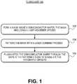
- FIG. 1is a Flowchart representing operations in a method of dicing a semiconductor wafer including a plurality of integrated circuits, in accordance with an embodiment of the present invention.
- FIG. 2Aillustrates a cross-sectional view of a semiconductor wafer including a plurality of integrated circuits during performing of a method of dicing the semiconductor wafer, corresponding to operation 102 of the Flowchart of FIG. 1 , in accordance with an embodiment of the present invention.
- FIG. 2Billustrates a cross-sectional view of a semiconductor wafer including a plurality of integrated circuits during performing of a method of dicing the semiconductor wafer, corresponding to operation 104 of the Flowchart of FIG. 1 , in accordance with an embodiment of the present invention.
- FIG. 2Cillustrates a cross-sectional view of a semiconductor wafer including a plurality of integrated circuits during performing of a method of dicing the semiconductor wafer, corresponding to operation 106 of the Flowchart of FIG. 1 , in accordance with an embodiment of the present invention.
- FIG. 3Aillustrates scanning electron microscope (SEM) images taken from a trench profile perspective following laser scribing but prior to mask removal for dye concentrations of 0%, 0.25% and 0.5%, in accordance with an embodiment of the present invention.
- SEMscanning electron microscope
- FIG. 3Billustrates scanning electron microscope (SEM) images and optical microscope images of trench surfaces following laser scribing mask removal for dye concentrations of 0%, 0.25% and 0.5%, in accordance with an embodiment of the present invention.
- SEMscanning electron microscope
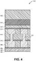
- FIG. 4illustrates a cross-sectional view of a stack of materials that may be used in a street region of a semiconductor wafer or substrate, in accordance with an embodiment of the present invention.
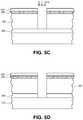
- FIGS. 5A-5Dillustrate cross-sectional views of various operations in a method of dicing a semiconductor wafer, in accordance with an embodiment of the present invention.
- FIG. 6illustrates a block diagram of a tool layout for laser and plasma dicing of wafers or substrates, in accordance with an embodiment of the present invention.
- FIG. 7illustrates a block diagram of an exemplary computer system, in accordance with an embodiment of the present invention.
- One or more embodimentsare directed particularly to using light-absorbers to reduce laser damage in etch masks.
- Embodimentsmay be applicable to laser and etch wafer dicing approaches and tooling for singulation or dicing of electronic device wafers.
- a laser and etch wafer dicing approachmay involve applying a water soluble protective coating to a substrate, removing the coating and device test layers in the street regions removed by laser scribing to open up the underlying substrate material, which is typically silicon (Si). The exposed Si is then plasma etched through its entire thickness to singulate the wafer into the individual die.
- the protective coatingis removed in a deionized (DI) water based cleaning operation.
- DIdeionized
- Water soluble protective coatingsmay be desirable due to environmental considerations and ease of processing. Such a water soluble coating may primarily be used as an etch mask during the plasma etching step, and also as a layer that collects any debris generated during laser scribing.
- femtosecond lasersmay be preferred in the laser scribing portion of the process. Unlike nanosecond and other long pulse lasers, femtosecond lasers have little heat effect because of the associated ultra-short pulses. Another advantage of femtosecond lasers may be the capability to remove most materials including absorptive, reflective and transparent materials. On typical wafers, there are metals which are reflective and absorptive, the dielectrics which are transparent, and the silicon substrate which is absorptive to most laser light. The water-soluble protective coating is totally or mostly transparent. These listed materials can be ablated by femtosecond lasers.
- Typical femtosecond lasershave a so-called “Gaussian beam,” which has high intensity near the center of the beam and low intensity toward the edge of the beam.
- Gaussian beamsmay become problematic when a femtosecond laser is used to process wafers with transparent layers on absorptive substrates, for example, a transparent protecting coating (e.g., water-soluble mask) on silicon or on dielectric layers on silicon.
- a laser processrequires a suitably high intensity (e.g., leading portion of a Gaussian beam) to produce nonlinear absorption.
- the low intensity portion (trailing portion) of the Gaussian beamdoes not have enough intensity to produce nonlinear absorption, the low intensity portion of the Gaussian beam passes through transparent layers with little attenuation. However, the low intensity portion of the Gaussian beam is absorbed by silicon. Such a scenario can cause heating of the transparent layer/silicon interface which can lead to delamination between the transparent layers and silicon, and to chipping or even cracking in both transparent layers and silicon. As a result, the Gaussian beam typically produces a laser damaged area, which is much wider than the intended scribe area. In another embodiment, however, the laser is not a Gaussian beam, but instead a non-Gaussian beam having high intensity portions and low intensity portions.
- light absorbersare used in a protective coating, such as in a water-soluble mask, to prevent the low intensity portion of the Gaussian beam from reaching the transparent layer/silicon interface.
- a laser damaged zoneis significantly reduced or removed altogether.
- inclusion of light-absorber species in an otherwise transparent mask materialenables a scribing process where a trailing portion of a Gaussian beam is kept in or confined to a mask during laser scribing, and permitting only a leading portion of the Gaussian beam to penetrate into substrate.
- laser scribing with other laser beam typesmay also be compatible with masking materials described herein. It is also to be appreciated that although many embodiments described below are associated with scribing streets having metallized features, in other embodiments, metal free scribing streets may also be considered.
- FIG. 1is a Flowchart 100 representing operations in a method of dicing a semiconductor wafer including a plurality of integrated circuits, in accordance with an embodiment of the present invention.
- FIGS. 2A-2Cillustrate cross-sectional views of a semiconductor wafer including a plurality of integrated circuits during performing of a method of dicing the semiconductor wafer, corresponding to operations of Flowchart 100 , in accordance with an embodiment of the present invention.
- a mask 202is formed above a semiconductor wafer or substrate 204 .
- the mask 202covers and protects integrated circuits 206 formed on the surface of semiconductor wafer 204 .
- the mask 202also covers intervening streets 207 formed between each of the integrated circuits 206 .
- the mask 202includes a water-soluble matrix based on a solid component and water, and a light-absorber species throughout the water-soluble matrix.
- the water soluble matrixis a polyvinyl alcohol (PVA)-based water soluble matrix, where the PVA is the solid component.
- PVApolyvinyl alcohol
- the solid component for the water soluble matrixis selected from the group consisting of polyethylene oxide, polyethylene glycol, polyacrylic acid, polyacrylamide, polystyrene-maleic acid copolymer, hydroxyethyl cellulose and hydroxyethyl starch.
- the water-soluble matrixincludes approximately 10-40 weight % of the solid component with the remainder water.
- forming the mask 202 above the semiconductor wafer 204includes spin-coating the mask 202 on the semiconductor wafer 204 .
- a plasma or chemical pre-treatmentis performed to enable better wettability and coating of the wafer.
- mask 202is a water soluble mask in that it is readily dissolvable in an aqueous media.
- the as deposited water-soluble mask 202is composed of a material that is soluble in one or more of an alkaline solution, an acidic solution, or in deionized water.
- the as-deposited water-soluble mask 202has an etch or removal rate in an aqueous solution approximately in the range of 1-15 microns per minute and, more particularly, approximately 1.3 microns per minute.
- the light-absorber species throughout the water-soluble matrix of the mask 202is a species such as, but not limited to a water-soluble dye dissolved in the water-soluble matrix, a nano-dispersion of pigments throughout the water-soluble matrix, or a combination of a water soluble dye dissolved in the water-soluble matrix and a nano-dispersion of pigments throughout the water-soluble matrix.
- the light absorber speciesis selected from the group consisting of Rhodamine B, Rhodamine G, and D&C red 27.
- the light absorber speciesis selected from the group of dyes or pigments that absorb 530 nm light, where examples of dyes are Rhodamine B, Rhodamine G, betanin and D&C red 27. It is to be appreciated that since a relatively larger pigment dispersion may scatter light and have a negative effect on wafer alignment, water-soluble dyes may be preferred light absorbers.
- a nano-dispersion of pigments(dispersion of pigment particles having a size on the nanometer scale) is used and exhibits relatively low light scattering.
- the dispersion of pigment particlesis composed of carbon black, iron oxide, or gold colloids.
- a dispersion of CeO 2 particlesis used as a UV-absorbing species.
- typical water soluble polymersdo not have high resistance to plasma etching, while polymers that have good etch resistance are typically not soluble in water.
- Etch selectivitymay be defined as the ratio of the amount of substrate material (e.g., Si) removed to the amount of mask loss during the etch process.
- Water soluble polymerstypically have relatively low selectivity, and it may be advantageous to enhance the selectivity of the mask without sacrificing water solubility.
- a light-absorbing water soluble maskhas additional particles therein provided for etch selectivity for laser scribing and plasma etching wafer singulation.
- Embodimentsmay address potential needs for improved etch resistance in a water soluble dicing mask.
- a polyvinyl alcohol (PVA) matrix with silica particles dispersed thereinis provided as an etch mask.
- particle dispersionsare mixed with water soluble polymers to form a composite mask. Materials such as oxides and polymers, which are not water soluble, can be incorporated into water soluble polymer mixtures as dispersions. Suitable particle dispersions may be colloidal dispersions of inorganic particles and polymers.
- Suitable inorganic particlesmay include oxide, such as silicon oxide, aluminum oxide, titanium oxide, and cerium oxide, and other particles such as calcium carbonate, barium sulfate, etc.
- Suitable polymer particlesmay include polystyrene and PTFE. It is to be appreciated that low haze is usually required for the mask since the mask is laser scribed. To minimize haze, in an embodiment, particles smaller than 100 nanometers may be included in the matrix.
- a plurality of particlesis dispersed throughout the water-soluble matrix of the mask that includes light-absorber species.
- the plurality of particlesis different from the light-absorber species.
- the plurality of particleshas an average diameter approximately in the range of 5-100 nanometers.
- a ratio of weight % of the solid component of the water-soluble matrix to weight % of the plurality of particlesis approximately in the range of 1:0.1-1:4.
- the plurality of particleshas an average diameter approximately in the range of 5-100 nanometers, and a ratio of weight % of the solid component of the water-soluble matrix to weight % of the plurality of particles is approximately in the range of 1:0.1-1:4.
- the plurality of particleshas an average diameter approximately in the range of 5-50 nanometers. It is to be appreciated that a smaller diameter may be preferable in order to mitigate or negate any potential laser light scattering or haze.
- the ratio of weight % of the solid component to weight % of the plurality of particlesis approximately in the range of 1:0.5-1:2.
- the plurality of particlesis a plurality of particles selected from the group consisting of silica (SiO 2 ) particles, alumina (Al 2 O 3 ) particles, alumina-coated silicon particles, polytetrafluoroethylene (PTFE) particles, and combinations thereof.
- silicaSiO 2
- Al 2 O 3alumina
- alumina-coated silicon particlesalumina-coated silicon particles
- PTFEpolytetrafluoroethylene
- Suitable polymer particlesalso include polystyrene, epoxies, etc.
- the plurality of particlesis a plurality of absorber species.
- semiconductor wafer or substrate 204is composed of a material suitable to withstand a fabrication process and upon which semiconductor processing layers may suitably be disposed.
- semiconductor wafer or substrate 204is composed of a group IV-based material such as, but not limited to, crystalline silicon, germanium or silicon/germanium.
- providing semiconductor wafer 204includes providing a monocrystalline silicon substrate.
- the monocrystalline silicon substrateis doped with impurity atoms.
- semiconductor wafer or substrate 204is composed of a III-V material such as, e.g., a III-V material substrate used in the fabrication of light emitting diodes (LEDs).
- LEDslight emitting diodes
- semiconductor wafer or substrate 204has disposed thereon or therein, as a portion of the integrated circuits 206 , an array of semiconductor devices.
- semiconductor devicesinclude, but are not limited to, memory devices or complimentary metal-oxide-semiconductor (CMOS) transistors fabricated in a silicon substrate and encased in a dielectric layer.
- CMOScomplimentary metal-oxide-semiconductor
- a plurality of metal interconnectsmay be formed above the devices or transistors, and in surrounding dielectric layers, and may be used to electrically couple the devices or transistors to form the integrated circuits 206 .
- Materials making up the streets 207may be similar to or the same as those materials used to form the integrated circuits 206 .
- streets 207may be composed of layers of dielectric materials, semiconductor materials, and metallization.
- one or more of the streets 207includes test devices similar to the actual devices of the integrated circuits 206 .
- the mask 202is baked prior to laser patterning of the mask. In an embodiment, the mask 202 is baked to increase the etch resistance of the mask 202 . In a specific embodiment, the mask 202 is baked at a relatively high temperature approximately in the range of 50 to 130 degrees Celsius. Such higher temperature baking may cause crosslink of the mask 202 so as to significantly increase etch resistance. For example, when the mask 202 is baked at or near 130 degrees Celsius for approximately 3 minutes, the resulting enhanced light-absorbing and etch resistant mask is robust against a silicon etch process. In one embodiment, baking is performed using a hot plate technique or a heat (light) radiation applied from the wafer front side (e.g., non-tape mounted side in the case of the use of a substrate carrier) or other suitable techniques.
- a hot plate technique or a heat (light) radiation applied from the wafer front sidee.g., non-tape mounted side in the case of the use of a substrate carrier
- the mask 202is patterned with a laser scribing process to provide patterned mask 208 with gaps 210 , exposing regions of the semiconductor wafer or substrate 204 between the integrated circuits 206 .
- the laser scribing processis used to remove the material of the streets 207 originally formed between the integrated circuits 206 .
- patterning the mask 202 with the laser scribing processfurther includes forming trenches 212 partially into the regions of the semiconductor wafer 204 between the integrated circuits 206 , as is also depicted in FIG. 2B .
- the mask 202is patterned with a Gaussian laser beam.
- the light-absorber species of the masksubstantially confines a trailing portion of the Gaussian beam to the mask 202 during the patterning.
- a leading portion of the Gaussian beamis substantially confined to the semiconductor wafer or substrate 204 during the patterning.
- the mask 202further includes a plurality of particles for increasing etch resistance, the plurality of particles of the mask 202 does not substantially interfere with the laser scribing process during the patterning of the mask 202 with the laser scribing process.
- a femtosecond-based laseris used as a source for a laser scribing process.
- a laser with a wavelength in the visible spectrum plus the ultra-violet (UV) and infra-red (IR) ranges (totaling a broadband optical spectrum)is used to provide a femtosecond-based laser, i.e., a laser with a pulse width on the order of the femtosecond (10 ⁇ 15 seconds).
- ablationis not, or is essentially not, wavelength dependent and is thus suitable for complex films such as films of the mask 202 , the streets 207 and, possibly, a portion of the semiconductor wafer or substrate 204 .
- FIG. 3Aillustrates scanning electron microscope (SEM) images taken from a trench profile perspective following laser scribing but prior to mask removal for dye concentrations of 0%, 0.25% and 0.5%, in accordance with an embodiment of the present invention.
- FIG. 3Billustrates scanning electron microscope (SEM) images and optical microscope images of trench surfaces following laser scribing mask removal for dye concentrations of 0%, 0.25% and 0.5%, in accordance with an embodiment of the present invention.
- transparent water-soluble mask sampleswere prepared to include no light absorber, 0.25 weight % light absorber and 0.5 weight % light absorber.
- the light absorber usedwas D&C Red 27.
- the water soluble mask materialswere coated on bare silicon (Si) wafers with the coating materials. The coatings were baked to dry. A laser scribe process was used to open the mask material. A plasma etch was performed to achieve a desired trench etch depth in the Si. The wafers were cleaved/cross-sectioned into samples to obtain SEM images and measurements of the width of laser affected areas. As shown in FIGS. 3A and 3B , 0.5% D&C red 27 significantly reduces the width of the laser damaged zones.
- laser parameter selectionsuch as beam profile, may be critical to developing a successful laser scribing and dicing process that minimizes chipping, microcracks and delamination in order to achieve clean laser scribe cuts. The cleaner the laser scribe cut, the smoother an etch process that may be performed for ultimate die singulation.
- Such materialsmay include, but are not limited to, organic materials such as polymers, metals, or inorganic dielectrics such as silicon dioxide and silicon nitride.
- FIG. 4illustrates a cross-sectional view of a stack of materials that may be used in a street region of a semiconductor wafer or substrate, in accordance with an embodiment of the present invention.
- a street region 400includes the top portion 402 of a silicon substrate, a first silicon dioxide layer 404 , a first etch stop layer 406 , a first low K dielectric layer 408 (e.g., having a dielectric constant of less than the dielectric constant of 4.0 for silicon dioxide), a second etch stop layer 410 , a second low K dielectric layer 412 , a third etch stop layer 414 , an undoped silica glass (USG) layer 416 , a second silicon dioxide layer 418 , and a scribing and/or etch mask 420 (such as a mask described above in association with mask 202 ).
- a street region 400includes the top portion 402 of a silicon substrate, a first silicon dioxide layer 404 , a first etch stop layer 406 , a first low K dielectric layer 408 (e.g., having a dielectric constant of less than the dielectric constant of 4.0 for silicon dioxide), a second etch stop layer 410 ,
- Copper metallization 422is disposed between the first and third etch stop layers 406 and 414 and through the second etch stop layer 410 .
- the first, second and third etch stop layers 406 , 410 and 414are composed of silicon nitride, while low K dielectric layers 408 and 412 are composed of a carbon-doped silicon oxide material.
- the materials of street 400behave quite differently in terms of optical absorption and ablation mechanisms.
- dielectrics layerssuch as silicon dioxide
- metals, organics (e.g., low K materials) and siliconcan couple photons very easily, particularly in response to nanosecond-based irradiation.
- a femto-second based laser scribing processis used to pattern a layer of silicon dioxide, a layer of low K material, and a layer of copper by ablating the layer of silicon dioxide prior to ablating the layer of low K material and the layer of copper.
- suitable femtosecond-based laser processesare characterized by a high peak intensity (irradiance) that usually leads to nonlinear interactions in various materials.
- the femtosecond laser sourceshave a pulse width approximately in the range of 10 femtoseconds to 500 femtoseconds, although preferably in the range of 100 femtoseconds to 400 femtoseconds.
- the femtosecond laser sourceshave a wavelength approximately in the range of 1570 nanometers to 200 nanometers, although preferably in the range of 540 nanometers to 250 nanometers.
- the laser and corresponding optical systemprovide a focal spot at the work surface approximately in the range of 3 microns to 15 microns, though preferably approximately in the range of 5 microns to 10 microns or between 10-15 microns.
- the laser sourcehas a pulse repetition rate approximately in the range of 200 kHz to 10 MHz, although preferably approximately in the range of 500 kHz to 5 MHz.
- the laser sourcedelivers pulse energy at the work surface approximately in the range of 0.5 uJ to 100 uJ, although preferably approximately in the range of 1 uJ to 5 uJ.
- the laser scribing processruns along a work piece surface at a speed approximately in the range of 500 mm/sec to 5 m/sec, although preferably approximately in the range of 600 mm/sec to 2 m/sec.
- the scribing processmay be run in single pass only, or in multiple passes, but, in an embodiment, preferably 1-2 passes.
- the scribing depth in the work pieceis approximately in the range of 5 microns to 50 microns deep, preferably approximately in the range of 10 microns to 20 microns deep.
- the kerf width of the laser beam generatedis approximately in the range of 2 microns to 15 microns, although in silicon wafer scribing/dicing preferably approximately in the range of 6 microns to 10 microns, measured at the device/silicon interface.
- Laser parametersmay be selected with benefits and advantages such as providing sufficiently high laser intensity to achieve ionization of inorganic dielectrics (e.g., silicon dioxide) and to minimize delamination and chipping caused by underlayer damage prior to direct ablation of inorganic dielectrics. Also, parameters may be selected to provide meaningful process throughput for industrial applications with precisely controlled ablation width (e.g., kerf width) and depth.
- inorganic dielectricse.g., silicon dioxide
- parametersmay be selected to provide meaningful process throughput for industrial applications with precisely controlled ablation width (e.g., kerf width) and depth.
- a method of dicing a semiconductor wafer including a plurality of integrated circuitsinvolves forming a mask above the semiconductor wafer.
- the maskincludes a water-soluble matrix based on a solid component and water, and a light-absorber species throughout the water-soluble matrix.
- the maskis patterned and the integrated circuits of the semiconductor wafer are singulated with a laser scribing process.
- the maskis patterned with a Gaussian beam.
- the light-absorber species of the masksubstantially confines a trailing portion of the Gaussian beam to the mask during the patterning.
- a leading portion of the Gaussian beamis substantially confined to the semiconductor wafer during the patterning.
- the laser scribingcompletes the singulation.
- further singulation processingsuch as plasma etching to effect singulation is not required.
- the embodiments that followmay be considered in cases where laser scribing alone is not implemented for total singulation.
- an intermediate post mask-opening cleaning operationis performed subsequent to the laser scribing process and prior to a plasma etching singulation process.
- the post mask-opening cleaning operationis a plasma-based cleaning process.
- the plasma-based cleaning processis non-reactive to the trenches 212 of the substrate 204 exposed by the gaps 210 .
- the plasma-based cleaning processis non-reactive to exposed regions of the substrate 204 in that the exposed regions are not or only negligible etched during the cleaning process.
- only non-reactive gas plasma cleaningis used.
- Ar or another non-reactive gas (or the mix)is used to perform a highly-biased plasma treatment both for mask condensation and cleaning of scribed openings.
- the approachmay be suitable for water-soluble masks such as mask 202 .
- separate mask condensation (densification of the surface layer) and scribed trench cleaning operationsare used, e.g., an Ar or non-reactive gas (or the mix) highly-biased plasma treatment for mask condensation is first performed, and then an Ar+SF 6 plasma cleaning of a laser scribed trench is performed.
- This embodimentmay be suitable for cases where Ar-cleaning is not sufficient for trench cleaning due to too thick of a mask material.
- etching the semiconductor wafer 204includes ultimately etching entirely through semiconductor wafer 204 , as depicted in FIG. 2C , by etching the trenches 212 initially formed with the laser scribing process.
- the patterned mask 208protects the integrated circuits during the plasma etching.
- plasma etching the semiconductor wafer through the gapsinvolves plasma etching a single crystalline silicon wafer.
- a ratio of an etch rate of the single crystalline silicon wafer to an etch rate of the mask 202is approximately in the range of 15:1-170:1 during the plasma etching.
- patterning the mask 202 with the laser scribing processinvolves forming trenches in the regions of the semiconductor wafer between the integrated circuits, and plasma etching the semiconductor wafer involves extending the trenches to form corresponding trench extensions.
- each of the trencheshas a width
- each of the corresponding trench extensionshas the width.
- etching the semiconductor wafer 204includes using a plasma etching process.
- a through-silicon via type etch processis used.
- the etch rate of the material of semiconductor wafer 204is greater than 25 microns per minute.
- An ultra-high-density plasma sourcemay be used for the plasma etching portion of the die singulation process.
- An example of a process chamber suitable to perform such a plasma etch processis the Applied Centura® SilviaTM Etch system available from Applied Materials of Sunnyvale, Calif., USA.
- the Applied Centura® SilviaTM Etch systemcombines the capacitive and inductive RF coupling, which gives much more independent control of the ion density and ion energy than was possible with the capacitive coupling only, even with the improvements provided by magnetic enhancement.
- This combinationenables effective decoupling of the ion density from ion energy, so as to achieve relatively high density plasmas without the high, potentially damaging, DC bias levels, even at very low pressures. This results in an exceptionally wide process window.
- any plasma etch chamber capable of etching siliconmay be used.
- a deep silicon etchis used to etch a single crystalline silicon substrate or wafer 204 at an etch rate greater than approximately 40% of conventional silicon etch rates while maintaining essentially precise profile control and virtually scallop-free sidewalls.
- a through-silicon via type etch processis used. The etch process is based on a plasma generated from a reactive gas, which is generally a fluorine-based gas such as SF 6 , C 4 F 8 , CHF 3 , XeF 2 , or any other reactant gas capable of etching silicon at a relatively fast etch rate.
- the light-absorbing water soluble patterned mask 208is removed after the singulation process, as depicted in FIG.
- the plasma etching operation described in association with FIG. 2Cemploys a conventional Bosch-type dep/etch/dep process to etch through the substrate 204 .
- a Bosch-type processconsists of three sub-operations: deposition, a directional bombardment etch, and isotropic chemical etch which is run through many iterations (cycles) until silicon is etched through.
- the patterned mask 208is removed.
- the patterned mask 208is removed using an aqueous solution.
- the patterned mask 208is removed by a hot aqueous treatment, such as a hot water treatment.
- the patterned mask 208is removed in a hot water treatment at a temperature approximately in the range of 40-100 degrees Celsius.
- the patterned mask 208is removed in a hot water treatment at a temperature approximately in the range of 80-90 degrees Celsius. It is to be appreciated that the hotter the temperature of the water, the less time may be needed for the hot water treatment.
- a plasma cleaning processcan also be performed after etching to aid in the removal of the patterned mask 208 .
- a relatively lower water treatment temperaturemay be employed, albeit for a longer duration that a relatively higher water treatment temperature.
- the water treatmentis between room temperature (i.e., the water is un-heated), but below a temperature of approximately 40 degrees Celsius.
- the patterned mask 208is removed in a warm water treatment at a temperature approximately in the range of 35-40 degrees Celsius.
- wafer dicingmay be preformed by initial ablation to ablate through an mask 202 , through wafer streets (including metallization), and partially into a silicon substrate. Die singulation may then be completed by subsequent through-silicon deep plasma etching.
- a specific example of a materials stack for dicingis described below in association with FIGS. 5A-5D , in accordance with an embodiment of the present invention.
- a materials stack for hybrid laser ablation and plasma etch dicingincludes a mask 502 , a device layer 504 , and a substrate 506 .
- the mask layer 502 , device layer 504 , and substrate 506are disposed above a die attach film 508 which is affixed to a backing tape 510 .
- direct coupling to a standard dicing tapeis used.
- the mask 502is one such as described above in association with mask 202 .
- the device layer 504includes an inorganic dielectric layer (such as silicon dioxide) disposed above one or more metal layers (such as copper layers) and one or more low K dielectric layers (such as carbon-doped oxide layers).
- the device layer 504also includes streets arranged between integrated circuits, the streets including the same or similar layers to the integrated circuits.
- the substrate 506is a bulk single-crystalline silicon substrate.
- the mask 502is fabricated using a thermal treatment or bake 599 , such as described above.
- the bulk single-crystalline silicon substrate 506is thinned from the backside prior to being affixed to the die attach film 508 .
- the thinningmay be performed by a backside grind process.
- the bulk single-crystalline silicon substrate 506is thinned to a thickness approximately in the range of 50-100 microns. It is important to note that, in an embodiment, the thinning is performed prior to a laser ablation and plasma etch dicing process.
- the mask 502has a thickness approximately in the range of 1-5 microns and the device layer 504 has a thickness approximately in the range of 2-3 microns.
- the die attach film 508(or any suitable substitute capable of bonding a thinned or thin wafer or substrate to the backing tape 510 , such as dicing tapes consisting of an upper adhesive layer and a base film) has a thickness approximately in the range of 10-200 microns.
- the mask 502 , the device layer 504 and a portion of the substrate 506are patterned with a laser scribing process 512 to form trenches 514 in the substrate 506 .
- a through-silicon deep plasma etch process 516is used to extend the trench 514 down to the die attach film 508 , exposing the top portion of the die attach film 508 and singulating the silicon substrate 506 .
- the device layer 504is protected by the mask 502 during the through-silicon deep plasma etch process 516 .
- the singulation processmay further include patterning the die attach film 508 , exposing the top portion of the backing tape 510 and singulating the die attach film 508 .
- the die attach filmis singulated by a laser process or by an etch process. Further embodiments may include subsequently removing the singulated portions of substrate 506 (e.g., as individual integrated circuits) from the backing tape 510 .
- the singulated die attach film 508is retained on the back sides of the singulated portions of substrate 506 .
- the laser scribing process 512is used to completely singulate substrate 506 without the use of an additional plasma process.
- Embodimentsmay further include removing the mask 502 from the device layer 504 . Removal of the mask 502 can be as described above for removal of the patterned mask 208 .
- a single process toolmay be configured to perform many or all of the operations in a hybrid laser ablation and plasma etch singulation process utilizing a light-absorbing water soluble mask.
- FIG. 6illustrates a block diagram of a tool layout for laser and plasma dicing of wafers or substrates, in accordance with an embodiment of the present invention.
- a process tool 600includes a factory interface 602 (FI) having a plurality of load locks 604 coupled therewith.
- a cluster tool 606is coupled with the factory interface 602 .
- the cluster tool 606includes one or more plasma etch chambers, such as plasma etch chamber 608 .
- a laser scribe apparatus 610is also coupled to the factory interface 602 .
- the overall footprint of the process tool 600may be, in one embodiment, approximately 3500 millimeters (3.5 meters) by approximately 3800 millimeters (3.8 meters), as depicted in FIG. 6 .
- the laser scribe apparatus 610houses a laser assembly configured to provide a femto-second based laser beam.
- the laseris suitable for performing a laser ablation portion of a hybrid laser and etch singulation process, such as the laser ablation processes described above.
- a moveable stageis also included in laser scribe apparatus 610 , the moveable stage configured for moving a wafer or substrate (or a carrier thereof) relative to the laser.
- the laseris also moveable.
- the overall footprint of the laser scribe apparatus 610may be, in one embodiment, approximately 2240 millimeters by approximately 1270 millimeters, as depicted in FIG. 6 .
- the one or more plasma etch chambers 608is configured for etching a wafer or substrate through the gaps in a patterned mask to singulate a plurality of integrated circuits.
- the one or more plasma etch chambers 608is configured to perform a deep silicon etch process.
- the one or more plasma etch chambers 608is an Applied Centura® SilviaTM Etch system, available from Applied Materials of Sunnyvale, Calif., USA.
- the etch chambermay be specifically designed for a deep silicon etch used to create singulate integrated circuits housed on or in single crystalline silicon substrates or wafers.
- a high-density plasma sourceis included in the plasma etch chamber 608 to facilitate high silicon etch rates.
- more than one etch chamberis included in the cluster tool 606 portion of process tool 600 to enable high manufacturing throughput of the singulation or dicing process.
- the factory interface 602may be a suitable atmospheric port to interface between an outside manufacturing facility with laser scribe apparatus 610 and cluster tool 606 .
- the factory interface 602may include robots with arms or blades for transferring wafers (or carriers thereof) from storage units (such as front opening unified pods) into either cluster tool 606 or laser scribe apparatus 610 , or both.
- Cluster tool 606may include other chambers suitable for performing functions in a method of singulation.
- a deposition and/or bake chamber 612is included.
- the deposition and/or bake chamber 612may be configured for mask deposition on or above a device layer of a wafer or substrate prior to laser scribing of the wafer or substrate.
- Such a mask materialmay be baked prior to the dicing process, as is described above.
- Such a mask materialmay be water soluble, as is also described above.
- a wet station 614is included.
- the wet stationmay be suitable for cleaning performing a room temperature or a hot aqueous treatment for removing a light-absorbing water soluble mask, as is described above, subsequent to a laser scribe and plasma etch singulation process of a substrate or wafer, or subsequent to a laser scribe-only singulation process.
- a metrology stationis also included as a component of process tool 600 .
- the cleaning chambercan include atomized mist and/or megasonics nozzle hardware that adds a physical component to the cleaning process, enhancing the dissolution rate of the mask.
- Embodiments of the present inventionmay be provided as a computer program product, or software, that may include a machine-readable medium having stored thereon instructions, which may be used to program a computer system (or other electronic devices) to perform a process according to embodiments of the present invention.
- the computer systemis coupled with process tool 600 described in association with FIG. 6 .
- a machine-readable mediumincludes any mechanism for storing or transmitting information in a form readable by a machine (e.g., a computer).
- a machine-readable (e.g., computer-readable) mediumincludes a machine (e.g., a computer) readable storage medium (e.g., read only memory (“ROM”), random access memory (“RAM”), magnetic disk storage media, optical storage media, flash memory devices, etc.), a machine (e.g., computer) readable transmission medium (electrical, optical, acoustical or other form of propagated signals (e.g., infrared signals, digital signals, etc.)), etc.
- FIG. 7illustrates a diagrammatic representation of a machine in the exemplary form of a computer system 700 within which a set of instructions, for causing the machine to perform any one or more of the methodologies described herein, may be executed.
- the machinemay be connected (e.g., networked) to other machines in a Local Area Network (LAN), an intranet, an extranet, or the Internet.
- LANLocal Area Network
- the machinemay operate in the capacity of a server or a client machine in a client-server network environment, or as a peer machine in a peer-to-peer (or distributed) network environment.
- the machinemay be a personal computer (PC), a tablet PC, a set-top box (STB), a Personal Digital Assistant (PDA), a cellular telephone, a web appliance, a server, a network router, switch or bridge, or any machine capable of executing a set of instructions (sequential or otherwise) that specify actions to be taken by that machine.
- PCpersonal computer
- PDAPersonal Digital Assistant
- STBset-top box
- WPAPersonal Digital Assistant
- the exemplary computer system 700includes a processor 702 , a main memory 704 (e.g., read-only memory (ROM), flash memory, dynamic random access memory (DRAM) such as synchronous DRAM (SDRAM) or Rambus DRAM (RDRAM), etc.), a static memory 706 (e.g., flash memory, static random access memory (SRAM), etc.), and a secondary memory 718 (e.g., a data storage device), which communicate with each other via a bus 730 .
- main memory 704e.g., read-only memory (ROM), flash memory, dynamic random access memory (DRAM) such as synchronous DRAM (SDRAM) or Rambus DRAM (RDRAM), etc.
- DRAMdynamic random access memory
- SDRAMsynchronous DRAM
- RDRAMRambus DRAM
- static memory 706e.g., flash memory, static random access memory (SRAM), etc.
- secondary memory 718e.g., a data storage device
- Processor 702represents one or more general-purpose processing devices such as a microprocessor, central processing unit, or the like. More particularly, the processor 702 may be a complex instruction set computing (CISC) microprocessor, reduced instruction set computing (RISC) microprocessor, very long instruction word (VLIW) microprocessor, processor implementing other instruction sets, or processors implementing a combination of instruction sets. Processor 702 may also be one or more special-purpose processing devices such as an application specific integrated circuit (ASIC), a field programmable gate array (FPGA), a digital signal processor (DSP), network processor, or the like. Processor 702 is configured to execute the processing logic 726 for performing the operations described herein.
- CISCcomplex instruction set computing
- RISCreduced instruction set computing
- VLIWvery long instruction word
- Processor 702may also be one or more special-purpose processing devices such as an application specific integrated circuit (ASIC), a field programmable gate array (FPGA), a digital signal processor (DSP), network processor, or the like.
- the computer system 700may further include a network interface device 708 .
- the computer system 700also may include a video display unit 710 (e.g., a liquid crystal display (LCD), a light emitting diode display (LED), or a cathode ray tube (CRT)), an alphanumeric input device 712 (e.g., a keyboard), a cursor control device 714 (e.g., a mouse), and a signal generation device 716 (e.g., a speaker).
- a video display unit 710e.g., a liquid crystal display (LCD), a light emitting diode display (LED), or a cathode ray tube (CRT)
- an alphanumeric input device 712e.g., a keyboard
- a cursor control device 714e.g., a mouse
- a signal generation device 716e.g., a speaker
- the secondary memory 718may include a machine-accessible storage medium (or more specifically a computer-readable storage medium) 732 on which is stored one or more sets of instructions (e.g., software 722 ) embodying any one or more of the methodologies or functions described herein.
- the software 722may also reside, completely or at least partially, within the main memory 704 and/or within the processor 702 during execution thereof by the computer system 700 , the main memory 704 and the processor 702 also constituting machine-readable storage media.
- the software 722may further be transmitted or received over a network 720 via the network interface device 708 .
- machine-accessible storage medium 732is shown in an exemplary embodiment to be a single medium, the term “machine-readable storage medium” should be taken to include a single medium or multiple media (e.g., a centralized or distributed database, and/or associated caches and servers) that store the one or more sets of instructions.
- the term “machine-readable storage medium”shall also be taken to include any medium that is capable of storing or encoding a set of instructions for execution by the machine and that cause the machine to perform any one or more of the methodologies of the present invention.
- the term “machine-readable storage medium”shall accordingly be taken to include, but not be limited to, solid-state memories, and optical and magnetic media.
- a machine-accessible storage mediumhas instructions stored thereon which cause a data processing system to perform a method of dicing a semiconductor wafer having a plurality of integrated circuits, such as one or more of the methods described herein.
Landscapes
- Engineering & Computer Science (AREA)
- Physics & Mathematics (AREA)
- Condensed Matter Physics & Semiconductors (AREA)
- General Physics & Mathematics (AREA)
- Manufacturing & Machinery (AREA)
- Computer Hardware Design (AREA)
- Microelectronics & Electronic Packaging (AREA)
- Power Engineering (AREA)
- Optics & Photonics (AREA)
- Plasma & Fusion (AREA)
- High Energy & Nuclear Physics (AREA)
- Mechanical Engineering (AREA)
- Electromagnetism (AREA)
- Health & Medical Sciences (AREA)
- Toxicology (AREA)
- Dicing (AREA)
- Laser Beam Processing (AREA)
- Drying Of Semiconductors (AREA)
Abstract
Description
Claims (17)
Priority Applications (6)
| Application Number | Priority Date | Filing Date | Title |
|---|---|---|---|
| US15/606,456US11158540B2 (en) | 2017-05-26 | 2017-05-26 | Light-absorbing mask for hybrid laser scribing and plasma etch wafer singulation process |
| JP2019565287AJP7181899B6 (en) | 2017-05-26 | 2018-05-11 | Light Absorbing Mask for Hybrid Laser Scribing and Plasma Etching Wafer Singulation Process |
| CN201880042815.2ACN110800097B (en) | 2017-05-26 | 2018-05-11 | Light Absorbing Masks for Hybrid Laser Scribing and Plasma Etching Wafer Dicing Processes |
| KR1020197038363AKR102566322B1 (en) | 2017-05-26 | 2018-05-11 | Light Absorption Mask for Hybrid Laser Scribing and Plasma Etch Wafer Singulation Process |
| PCT/US2018/032444WO2018217481A1 (en) | 2017-05-26 | 2018-05-11 | Light-absorbing mask for hybrid laser scribing and plasma etch wafer singulation process |
| EP18805731.9AEP3631848B1 (en) | 2017-05-26 | 2018-05-11 | Light-absorbing mask for hybrid laser scribing and plasma etch wafer singulation process |
Applications Claiming Priority (1)
| Application Number | Priority Date | Filing Date | Title |
|---|---|---|---|
| US15/606,456US11158540B2 (en) | 2017-05-26 | 2017-05-26 | Light-absorbing mask for hybrid laser scribing and plasma etch wafer singulation process |
Publications (2)
| Publication Number | Publication Date |
|---|---|
| US20180342422A1 US20180342422A1 (en) | 2018-11-29 |
| US11158540B2true US11158540B2 (en) | 2021-10-26 |
Family
ID=64395895
Family Applications (1)
| Application Number | Title | Priority Date | Filing Date |
|---|---|---|---|
| US15/606,456Active2038-02-24US11158540B2 (en) | 2017-05-26 | 2017-05-26 | Light-absorbing mask for hybrid laser scribing and plasma etch wafer singulation process |
Country Status (6)
| Country | Link |
|---|---|
| US (1) | US11158540B2 (en) |
| EP (1) | EP3631848B1 (en) |
| JP (1) | JP7181899B6 (en) |
| KR (1) | KR102566322B1 (en) |
| CN (1) | CN110800097B (en) |
| WO (1) | WO2018217481A1 (en) |
Families Citing this family (14)
| Publication number | Priority date | Publication date | Assignee | Title |
|---|---|---|---|---|
| JP7042437B2 (en)* | 2017-09-07 | 2022-03-28 | パナソニックIpマネジメント株式会社 | Method of manufacturing element chips |
| JP2019071333A (en)* | 2017-10-06 | 2019-05-09 | 株式会社ディスコ | Wafer processing method |
| CN113039628A (en) | 2018-11-15 | 2021-06-25 | 东京应化工业株式会社 | Protective film forming agent for plasma dicing and method for manufacturing semiconductor chip |
| US10818551B2 (en)* | 2019-01-09 | 2020-10-27 | Semiconductor Components Industries, Llc | Plasma die singulation systems and related methods |
| EP3931272B1 (en)* | 2019-02-27 | 2024-07-17 | John Cleaon Moore | Water washable thermal and plasma resistant coating for laser interactive applications |
| IT201900006740A1 (en)* | 2019-05-10 | 2020-11-10 | Applied Materials Inc | SUBSTRATE STRUCTURING PROCEDURES |
| CN114830301B (en)* | 2019-12-24 | 2025-04-01 | 东京应化工业株式会社 | Protective film forming agent and method for producing semiconductor chip |
| US11211247B2 (en)* | 2020-01-30 | 2021-12-28 | Applied Materials, Inc. | Water soluble organic-inorganic hybrid mask formulations and their applications |
| CN111822886B (en)* | 2020-06-11 | 2022-11-22 | 华东师范大学重庆研究院 | A multi-focus ultrafast laser preparation device and method for microfluidic chip microchannels |
| US11901232B2 (en)* | 2020-06-22 | 2024-02-13 | Applied Materials, Inc. | Automatic kerf offset mapping and correction system for laser dicing |
| US11854888B2 (en) | 2020-06-22 | 2023-12-26 | Applied Materials, Inc. | Laser scribing trench opening control in wafer dicing using hybrid laser scribing and plasma etch approach |
| US11804416B2 (en)* | 2020-09-08 | 2023-10-31 | UTAC Headquarters Pte. Ltd. | Semiconductor device and method of forming protective layer around cavity of semiconductor die |
| JP2022125002A (en)* | 2021-02-16 | 2022-08-26 | 東京応化工業株式会社 | Semiconductor chip manufacturing method and protective film forming agent |
| JP2025529422A (en)* | 2022-09-19 | 2025-09-04 | ラム リサーチ コーポレーション | Plasma-exposed parts with etch-resistant materials - Patent Application 20070122997 |
Citations (90)
| Publication number | Priority date | Publication date | Assignee | Title |
|---|---|---|---|---|
| US4049944A (en) | 1973-02-28 | 1977-09-20 | Hughes Aircraft Company | Process for fabricating small geometry semiconductive devices including integrated components |
| US4339528A (en) | 1981-05-19 | 1982-07-13 | Rca Corporation | Etching method using a hardened PVA stencil |
| US4684437A (en) | 1985-10-31 | 1987-08-04 | International Business Machines Corporation | Selective metal etching in metal/polymer structures |
| US4990417A (en)* | 1987-02-23 | 1991-02-05 | Sony Corporation | Method of manufacturing a cathode ray tube |
| US5336638A (en) | 1991-03-06 | 1994-08-09 | Hitachi, Ltd. | Process for manufacturing semiconductor devices |
| US5593606A (en) | 1994-07-18 | 1997-01-14 | Electro Scientific Industries, Inc. | Ultraviolet laser system and method for forming vias in multi-layered targets |
| JPH09216085A (en) | 1996-02-07 | 1997-08-19 | Canon Inc | Substrate cutting method and cutting device |
| US5691794A (en) | 1993-02-01 | 1997-11-25 | Canon Kabushiki Kaisha | Liquid crystal display device |
| JPH10321908A (en) | 1997-05-19 | 1998-12-04 | Nichia Chem Ind Ltd | Method for manufacturing nitride compound semiconductor device and semiconductor light emitting device |
| US6051503A (en) | 1996-08-01 | 2000-04-18 | Surface Technology Systems Limited | Method of surface treatment of semiconductor substrates |
| US6057180A (en) | 1998-06-05 | 2000-05-02 | Electro Scientific Industries, Inc. | Method of severing electrically conductive links with ultraviolet laser output |
| US6174271B1 (en) | 1997-03-09 | 2001-01-16 | Electro Scientific Industries, Inc. | High throughput hole forming system with multiple spindles per station |
| JP2001127011A (en) | 1999-10-26 | 2001-05-11 | Disco Abrasive Syst Ltd | Semiconductor wafer splitting method |
| JP2001144126A (en) | 1999-11-12 | 2001-05-25 | Matsushita Electric Ind Co Ltd | Semiconductor device manufacturing method and semiconductor device |
| US20010003643A1 (en)* | 1999-12-06 | 2001-06-14 | Nobuyuki Kita | Heat-sensitive lithographic printing plate precursor |
| US6300593B1 (en) | 1999-12-07 | 2001-10-09 | First Solar, Llc | Apparatus and method for laser scribing a coated substrate |
| US6306731B1 (en) | 1999-10-08 | 2001-10-23 | Oki Electric Industry Co., Ltd. | Semiconductor device and method for fabricating the same |
| US6407363B2 (en) | 2000-03-30 | 2002-06-18 | Electro Scientific Industries, Inc. | Laser system and method for single press micromachining of multilayer workpieces |
| US6426275B1 (en) | 1999-08-03 | 2002-07-30 | Tokyo Seimitsu Co., Ltd. | Method for manufacturing semiconductor chips using protecting pricing and separating sheets |
| JP2002221801A (en) | 2001-01-29 | 2002-08-09 | Hitachi Ltd | Wiring board manufacturing method |
| US6528864B1 (en) | 1999-11-19 | 2003-03-04 | Disco Corporation | Semiconductor wafer having regular or irregular chip pattern and dicing method for the same |
| WO2003036712A1 (en) | 2001-10-19 | 2003-05-01 | Applied Materials, Inc. | Method and apparatus for dicing a semiconductor wafer |
| US6574250B2 (en) | 2000-01-10 | 2003-06-03 | Electro Scientific Industries, Inc. | Laser system and method for processing a memory link with a burst of laser pulses having ultrashort pulse widths |
| US6582983B1 (en) | 2002-07-12 | 2003-06-24 | Keteca Singapore Singapore | Method and wafer for maintaining ultra clean bonding pads on a wafer |
| JP2003179005A (en) | 2001-12-13 | 2003-06-27 | Tokyo Electron Ltd | Method and device for separating semiconductor devices |
| US6593542B2 (en) | 2000-07-12 | 2003-07-15 | Electro Scientific Industries, Inc. | UV laser system and method for single pulse severing of IC fuses |
| WO2003071591A1 (en) | 2002-02-25 | 2003-08-28 | Disco Corporation | Method for dividing semiconductor wafer |
| US20030162313A1 (en) | 2002-02-25 | 2003-08-28 | Samsung Electronics Co., Ltd. | Method for sawing wafer |
| US6676878B2 (en) | 2001-01-31 | 2004-01-13 | Electro Scientific Industries, Inc. | Laser segmented cutting |
| JP2004031526A (en) | 2002-06-24 | 2004-01-29 | Toyoda Gosei Co Ltd | Manufacturing method of group iii nitride compound semiconductor element |
| JP2004055684A (en) | 2002-07-17 | 2004-02-19 | Shinko Electric Ind Co Ltd | Semiconductor device and its manufacturing method |
| US6696669B2 (en) | 1996-09-10 | 2004-02-24 | Micron Technology, Inc. | Circuit and method for heating an adhesive to package or rework a semiconductor die |
| US6706998B2 (en) | 2002-01-11 | 2004-03-16 | Electro Scientific Industries, Inc. | Simulated laser spot enlargement |
| US20040080045A1 (en) | 2002-10-28 | 2004-04-29 | Sharp Kabushiki Kaisha | Semiconductor device and chip-stack semiconductor device |
| US6759275B1 (en) | 2001-09-04 | 2004-07-06 | Megic Corporation | Method for making high-performance RF integrated circuits |
| US20040157457A1 (en) | 2003-02-12 | 2004-08-12 | Songlin Xu | Methods of using polymer films to form micro-structures |
| US6803247B2 (en) | 2002-02-28 | 2004-10-12 | Disco Corporation | Method for dividing semiconductor wafer |
| US20040212047A1 (en) | 2003-04-22 | 2004-10-28 | Joshi Subhash M. | Edge arrangements for integrated circuit chips |
| US6887804B2 (en) | 2000-01-10 | 2005-05-03 | Electro Scientific Industries, Inc. | Passivation processing over a memory link |
| US6998571B2 (en) | 2003-04-25 | 2006-02-14 | Disco Corporation | Laser beam processing machine |
| US20060043535A1 (en) | 2004-08-24 | 2006-03-02 | Hiatt William M | Pass through via technology for use during the manufacture of a semiconductor device |
| US20060088984A1 (en) | 2004-10-21 | 2006-04-27 | Intel Corporation | Laser ablation method |
| US20060086898A1 (en) | 2004-10-26 | 2006-04-27 | Matsushita Electric Industrial Co., Ltd. | Method and apparatus of making highly repetitive micro-pattern using laser writer |
| US20060146910A1 (en) | 2004-11-23 | 2006-07-06 | Manoochehr Koochesfahani | Method and apparatus for simultaneous velocity and temperature measurements in fluid flow |
| US20060205182A1 (en) | 2005-03-10 | 2006-09-14 | Nec Electronics Corporation | Method for manufacturing semiconductor device |
| US7129150B2 (en) | 2003-03-11 | 2006-10-31 | Disco Corporation | Method of dividing a semiconductor wafer |
| US7128806B2 (en) | 2003-10-21 | 2006-10-31 | Applied Materials, Inc. | Mask etch processing apparatus |
| US7179723B2 (en) | 2003-11-18 | 2007-02-20 | Disco Corporation | Wafer processing method |
| US20070120271A1 (en) | 2005-11-29 | 2007-05-31 | Shin-Etsu Chemical Co., Ltd. | Dicing and die bonding adhesive tape |
| US7265033B2 (en) | 2003-07-02 | 2007-09-04 | Disco Corporation | Laser beam processing method for a semiconductor wafer |
| US7361990B2 (en) | 2005-03-17 | 2008-04-22 | Taiwan Semiconductor Manufacturing Company, Ltd. | Reducing cracking of high-lead or lead-free bumps by matching sizes of contact pads and bump pads |
| US7364986B2 (en) | 2003-09-26 | 2008-04-29 | Disco Corporation | Laser beam processing method and laser beam machine |
| US7435607B2 (en) | 2004-01-15 | 2008-10-14 | Disco Corporation | Method of wafer laser processing using a gas permeable protective tape |
| US7459377B2 (en) | 2004-06-08 | 2008-12-02 | Panasonic Corporation | Method for dividing substrate |
| US7468309B2 (en) | 2005-03-29 | 2008-12-23 | Disco Corporation | Semiconductor wafer treatment method |
| US7473866B2 (en) | 2005-07-12 | 2009-01-06 | Disco Corporation | Laser processing apparatus |
| US7507638B2 (en) | 2004-06-30 | 2009-03-24 | Freescale Semiconductor, Inc. | Ultra-thin die and method of fabricating same |
| US7507639B2 (en) | 2005-12-06 | 2009-03-24 | Disco Corporation | Wafer dividing method |
| US20090255911A1 (en) | 2008-04-10 | 2009-10-15 | Applied Materials, Inc. | Laser scribing platform and hybrid writing strategy |
| US7629228B2 (en) | 2004-08-02 | 2009-12-08 | Panasonic Corporation | Manufacturing method for semiconductor devices, and formation apparatus for semiconductor wafer dicing masks |
| US20100013036A1 (en) | 2008-07-16 | 2010-01-21 | Carey James E | Thin Sacrificial Masking Films for Protecting Semiconductors From Pulsed Laser Process |
| US20100062269A1 (en)* | 2006-10-25 | 2010-03-11 | Tetra Laval Holdings & Finance S.A. | Laminated paper package material and method of producing the same |
| US7678670B2 (en) | 2004-12-24 | 2010-03-16 | Panasonic Corporation | TEG removing method in manufacturing method for semiconductor chips |
| US7687740B2 (en) | 2004-06-18 | 2010-03-30 | Electro Scientific Industries, Inc. | Semiconductor structure processing using multiple laterally spaced laser beam spots delivering multiple blows |
| US7754584B2 (en) | 2006-05-12 | 2010-07-13 | Panasonic Corporation | Semiconductor substrate, and semiconductor device and method of manufacturing the semiconductor device |
| US7767551B2 (en) | 2006-10-06 | 2010-08-03 | Panasonic Corporation | Method for fabricating semiconductor chip |
| US7767554B2 (en) | 2007-03-09 | 2010-08-03 | Panasonic Corporation | Method of manufacturing semicondictor chip |
| US7776720B2 (en) | 2002-04-19 | 2010-08-17 | Electro Scientific Industries, Inc. | Program-controlled dicing of a substrate using a pulsed laser |
| US20100216313A1 (en) | 2007-10-12 | 2010-08-26 | Panasonic Corproation | Plasma processing apparatus |
| US7804043B2 (en) | 2004-06-15 | 2010-09-28 | Laserfacturing Inc. | Method and apparatus for dicing of thin and ultra thin semiconductor wafer using ultrafast pulse laser |
| US20100248451A1 (en) | 2009-03-27 | 2010-09-30 | Electro Sceintific Industries, Inc. | Method for Laser Singulation of Chip Scale Packages on Glass Substrates |
| KR20100121939A (en) | 2009-05-11 | 2010-11-19 | 에스티에스반도체통신 주식회사 | A screen printing mask and method for plasma dicing using the same |
| US7838323B2 (en) | 2006-06-09 | 2010-11-23 | Panasonic Corporation | Method for fabricating semiconductor device |
| US7859084B2 (en) | 2008-02-28 | 2010-12-28 | Panasonic Corporation | Semiconductor substrate |
| US20110014777A1 (en) | 2008-03-25 | 2011-01-20 | Hiroshi Haji | Method for processing a substrate, method for manufacturing a semiconductor chip, and method for manufacturing a semiconductor chip having a resin adhesive layer |
| US7875898B2 (en) | 2005-01-24 | 2011-01-25 | Panasonic Corporation | Semiconductor device |
| US7906410B2 (en) | 2007-02-08 | 2011-03-15 | Panasonic Corporation | Method of manufacturing semiconductor chip using laser light and plasma dicing |
| US7923351B2 (en) | 2005-07-11 | 2011-04-12 | Panasonic Corporation | Manufacturing method of semiconductor devices |
| US7927973B2 (en) | 2004-10-05 | 2011-04-19 | Panasonic Corporation | Method for dividing semiconductor wafer and manufacturing method for semiconductor devices |
| US7926410B2 (en) | 2007-05-01 | 2011-04-19 | J.R. Automation Technologies, L.L.C. | Hydraulic circuit for synchronized horizontal extension of cylinders |
| US20110312157A1 (en) | 2010-06-22 | 2011-12-22 | Wei-Sheng Lei | Wafer dicing using femtosecond-based laser and plasma etch |
| US20130045554A1 (en) | 2007-08-29 | 2013-02-21 | Semiconductor Energy Laboratory Co., Ltd. | Display device and electronic appliance including the display device |
| US20130065378A1 (en) | 2011-03-14 | 2013-03-14 | Chris Johnson | Method and Apparatus for Plasma Dicing a Semi-conductor Wafer |
| US20130299088A1 (en) | 2011-06-15 | 2013-11-14 | Wei-Sheng Lei | Laser and plasma etch wafer dicing using water-soluble die attach film |
| US20140273401A1 (en)* | 2013-03-14 | 2014-09-18 | Wei-Sheng Lei | Substrate laser dicing mask including laser energy absorbing water-soluble film |
| US20150214111A1 (en) | 2014-01-29 | 2015-07-30 | Wei-Sheng Lei | Water soluble mask formation by dry film vacuum lamination for laser and plasma dicing |
| US9130030B1 (en)* | 2014-03-07 | 2015-09-08 | Applied Materials, Inc. | Baking tool for improved wafer coating process |
| US20160307851A1 (en)* | 2015-04-17 | 2016-10-20 | Disco Corporation | Method of dividing wafer |
| US20160365283A1 (en)* | 2015-06-12 | 2016-12-15 | Wei-Sheng Lei | Etch-resistant water soluble mask for hybrid wafer dicing using laser scribing and plasma etch |
| WO2017196549A1 (en) | 2016-05-13 | 2017-11-16 | Applied Materials, Inc. | Etch mask for hybrid laser scribing and plasma etch wafer singulation process |
Family Cites Families (9)
| Publication number | Priority date | Publication date | Assignee | Title |
|---|---|---|---|---|
| US6491835B1 (en)* | 1999-12-20 | 2002-12-10 | Applied Materials, Inc. | Metal mask etching of silicon |
| JP2002341525A (en)* | 2001-05-14 | 2002-11-27 | Fuji Photo Film Co Ltd | Positive photoresist transfer material and substrate surface processing method using the same |
| JP4571850B2 (en)* | 2004-11-12 | 2010-10-27 | 東京応化工業株式会社 | Protective film agent for laser dicing and wafer processing method using the protective film agent |
| JP4873863B2 (en)* | 2005-01-14 | 2012-02-08 | 日東電工株式会社 | Manufacturing method of laser processed product and pressure-sensitive adhesive sheet for laser processing |
| US8859397B2 (en)* | 2012-07-13 | 2014-10-14 | Applied Materials, Inc. | Method of coating water soluble mask for laser scribing and plasma etch |
| US20150243559A1 (en)* | 2014-02-27 | 2015-08-27 | Jungrae Park | Hybrid wafer dicing approach using temporally-controlled laser scribing process and plasma etch |
| US9349648B2 (en)* | 2014-07-22 | 2016-05-24 | Applied Materials, Inc. | Hybrid wafer dicing approach using a rectangular shaped two-dimensional top hat laser beam profile or a linear shaped one-dimensional top hat laser beam profile laser scribing process and plasma etch process |
| US9196536B1 (en)* | 2014-09-25 | 2015-11-24 | Applied Materials, Inc. | Hybrid wafer dicing approach using a phase modulated laser beam profile laser scribing process and plasma etch process |
| US9245803B1 (en)* | 2014-10-17 | 2016-01-26 | Applied Materials, Inc. | Hybrid wafer dicing approach using a bessel beam shaper laser scribing process and plasma etch process |
- 2017
- 2017-05-26USUS15/606,456patent/US11158540B2/enactiveActive
- 2018
- 2018-05-11EPEP18805731.9Apatent/EP3631848B1/enactiveActive
- 2018-05-11CNCN201880042815.2Apatent/CN110800097B/enactiveActive
- 2018-05-11JPJP2019565287Apatent/JP7181899B6/enactiveActive
- 2018-05-11WOPCT/US2018/032444patent/WO2018217481A1/ennot_activeCeased
- 2018-05-11KRKR1020197038363Apatent/KR102566322B1/enactiveActive
Patent Citations (94)
| Publication number | Priority date | Publication date | Assignee | Title |
|---|---|---|---|---|
| US4049944A (en) | 1973-02-28 | 1977-09-20 | Hughes Aircraft Company | Process for fabricating small geometry semiconductive devices including integrated components |
| US4339528A (en) | 1981-05-19 | 1982-07-13 | Rca Corporation | Etching method using a hardened PVA stencil |
| US4684437A (en) | 1985-10-31 | 1987-08-04 | International Business Machines Corporation | Selective metal etching in metal/polymer structures |
| US4990417A (en)* | 1987-02-23 | 1991-02-05 | Sony Corporation | Method of manufacturing a cathode ray tube |
| US5336638A (en) | 1991-03-06 | 1994-08-09 | Hitachi, Ltd. | Process for manufacturing semiconductor devices |
| US5691794A (en) | 1993-02-01 | 1997-11-25 | Canon Kabushiki Kaisha | Liquid crystal display device |
| US5593606A (en) | 1994-07-18 | 1997-01-14 | Electro Scientific Industries, Inc. | Ultraviolet laser system and method for forming vias in multi-layered targets |
| JPH09216085A (en) | 1996-02-07 | 1997-08-19 | Canon Inc | Substrate cutting method and cutting device |
| US6051503A (en) | 1996-08-01 | 2000-04-18 | Surface Technology Systems Limited | Method of surface treatment of semiconductor substrates |
| US6696669B2 (en) | 1996-09-10 | 2004-02-24 | Micron Technology, Inc. | Circuit and method for heating an adhesive to package or rework a semiconductor die |
| US6174271B1 (en) | 1997-03-09 | 2001-01-16 | Electro Scientific Industries, Inc. | High throughput hole forming system with multiple spindles per station |
| JPH10321908A (en) | 1997-05-19 | 1998-12-04 | Nichia Chem Ind Ltd | Method for manufacturing nitride compound semiconductor device and semiconductor light emitting device |
| US6057180A (en) | 1998-06-05 | 2000-05-02 | Electro Scientific Industries, Inc. | Method of severing electrically conductive links with ultraviolet laser output |
| US6426275B1 (en) | 1999-08-03 | 2002-07-30 | Tokyo Seimitsu Co., Ltd. | Method for manufacturing semiconductor chips using protecting pricing and separating sheets |
| US6306731B1 (en) | 1999-10-08 | 2001-10-23 | Oki Electric Industry Co., Ltd. | Semiconductor device and method for fabricating the same |
| JP2001127011A (en) | 1999-10-26 | 2001-05-11 | Disco Abrasive Syst Ltd | Semiconductor wafer splitting method |
| US6465158B1 (en) | 1999-10-26 | 2002-10-15 | Disco Corporation | Semiconductor wafer dividing method |
| JP2001144126A (en) | 1999-11-12 | 2001-05-25 | Matsushita Electric Ind Co Ltd | Semiconductor device manufacturing method and semiconductor device |
| US6528864B1 (en) | 1999-11-19 | 2003-03-04 | Disco Corporation | Semiconductor wafer having regular or irregular chip pattern and dicing method for the same |
| US20010003643A1 (en)* | 1999-12-06 | 2001-06-14 | Nobuyuki Kita | Heat-sensitive lithographic printing plate precursor |
| US6300593B1 (en) | 1999-12-07 | 2001-10-09 | First Solar, Llc | Apparatus and method for laser scribing a coated substrate |
| US6574250B2 (en) | 2000-01-10 | 2003-06-03 | Electro Scientific Industries, Inc. | Laser system and method for processing a memory link with a burst of laser pulses having ultrashort pulse widths |
| US6887804B2 (en) | 2000-01-10 | 2005-05-03 | Electro Scientific Industries, Inc. | Passivation processing over a memory link |
| US6407363B2 (en) | 2000-03-30 | 2002-06-18 | Electro Scientific Industries, Inc. | Laser system and method for single press micromachining of multilayer workpieces |
| US6593542B2 (en) | 2000-07-12 | 2003-07-15 | Electro Scientific Industries, Inc. | UV laser system and method for single pulse severing of IC fuses |
| JP2002221801A (en) | 2001-01-29 | 2002-08-09 | Hitachi Ltd | Wiring board manufacturing method |
| US6676878B2 (en) | 2001-01-31 | 2004-01-13 | Electro Scientific Industries, Inc. | Laser segmented cutting |
| US6759275B1 (en) | 2001-09-04 | 2004-07-06 | Megic Corporation | Method for making high-performance RF integrated circuits |
| WO2003036712A1 (en) | 2001-10-19 | 2003-05-01 | Applied Materials, Inc. | Method and apparatus for dicing a semiconductor wafer |
| US6642127B2 (en) | 2001-10-19 | 2003-11-04 | Applied Materials, Inc. | Method for dicing a semiconductor wafer |
| JP2003179005A (en) | 2001-12-13 | 2003-06-27 | Tokyo Electron Ltd | Method and device for separating semiconductor devices |
| US6706998B2 (en) | 2002-01-11 | 2004-03-16 | Electro Scientific Industries, Inc. | Simulated laser spot enlargement |
| WO2003071591A1 (en) | 2002-02-25 | 2003-08-28 | Disco Corporation | Method for dividing semiconductor wafer |
| US20030162313A1 (en) | 2002-02-25 | 2003-08-28 | Samsung Electronics Co., Ltd. | Method for sawing wafer |
| US20040137700A1 (en) | 2002-02-25 | 2004-07-15 | Kazuma Sekiya | Method for dividing semiconductor wafer |
| US6803247B2 (en) | 2002-02-28 | 2004-10-12 | Disco Corporation | Method for dividing semiconductor wafer |
| US7776720B2 (en) | 2002-04-19 | 2010-08-17 | Electro Scientific Industries, Inc. | Program-controlled dicing of a substrate using a pulsed laser |
| JP2004031526A (en) | 2002-06-24 | 2004-01-29 | Toyoda Gosei Co Ltd | Manufacturing method of group iii nitride compound semiconductor element |
| US6582983B1 (en) | 2002-07-12 | 2003-06-24 | Keteca Singapore Singapore | Method and wafer for maintaining ultra clean bonding pads on a wafer |
| JP2004055684A (en) | 2002-07-17 | 2004-02-19 | Shinko Electric Ind Co Ltd | Semiconductor device and its manufacturing method |
| US20040080045A1 (en) | 2002-10-28 | 2004-04-29 | Sharp Kabushiki Kaisha | Semiconductor device and chip-stack semiconductor device |
| US20040157457A1 (en) | 2003-02-12 | 2004-08-12 | Songlin Xu | Methods of using polymer films to form micro-structures |
| US7129150B2 (en) | 2003-03-11 | 2006-10-31 | Disco Corporation | Method of dividing a semiconductor wafer |
| US20040212047A1 (en) | 2003-04-22 | 2004-10-28 | Joshi Subhash M. | Edge arrangements for integrated circuit chips |
| US6998571B2 (en) | 2003-04-25 | 2006-02-14 | Disco Corporation | Laser beam processing machine |
| US7265033B2 (en) | 2003-07-02 | 2007-09-04 | Disco Corporation | Laser beam processing method for a semiconductor wafer |
| US7364986B2 (en) | 2003-09-26 | 2008-04-29 | Disco Corporation | Laser beam processing method and laser beam machine |
| US7128806B2 (en) | 2003-10-21 | 2006-10-31 | Applied Materials, Inc. | Mask etch processing apparatus |
| US7179723B2 (en) | 2003-11-18 | 2007-02-20 | Disco Corporation | Wafer processing method |
| US7435607B2 (en) | 2004-01-15 | 2008-10-14 | Disco Corporation | Method of wafer laser processing using a gas permeable protective tape |
| US7459377B2 (en) | 2004-06-08 | 2008-12-02 | Panasonic Corporation | Method for dividing substrate |
| US7804043B2 (en) | 2004-06-15 | 2010-09-28 | Laserfacturing Inc. | Method and apparatus for dicing of thin and ultra thin semiconductor wafer using ultrafast pulse laser |
| US7687740B2 (en) | 2004-06-18 | 2010-03-30 | Electro Scientific Industries, Inc. | Semiconductor structure processing using multiple laterally spaced laser beam spots delivering multiple blows |
| US7507638B2 (en) | 2004-06-30 | 2009-03-24 | Freescale Semiconductor, Inc. | Ultra-thin die and method of fabricating same |
| US7629228B2 (en) | 2004-08-02 | 2009-12-08 | Panasonic Corporation | Manufacturing method for semiconductor devices, and formation apparatus for semiconductor wafer dicing masks |
| US20060043535A1 (en) | 2004-08-24 | 2006-03-02 | Hiatt William M | Pass through via technology for use during the manufacture of a semiconductor device |
| US7927973B2 (en) | 2004-10-05 | 2011-04-19 | Panasonic Corporation | Method for dividing semiconductor wafer and manufacturing method for semiconductor devices |
| US20060088984A1 (en) | 2004-10-21 | 2006-04-27 | Intel Corporation | Laser ablation method |
| US20060086898A1 (en) | 2004-10-26 | 2006-04-27 | Matsushita Electric Industrial Co., Ltd. | Method and apparatus of making highly repetitive micro-pattern using laser writer |
| US20060146910A1 (en) | 2004-11-23 | 2006-07-06 | Manoochehr Koochesfahani | Method and apparatus for simultaneous velocity and temperature measurements in fluid flow |
| US7678670B2 (en) | 2004-12-24 | 2010-03-16 | Panasonic Corporation | TEG removing method in manufacturing method for semiconductor chips |
| US7875898B2 (en) | 2005-01-24 | 2011-01-25 | Panasonic Corporation | Semiconductor device |
| US20060205182A1 (en) | 2005-03-10 | 2006-09-14 | Nec Electronics Corporation | Method for manufacturing semiconductor device |
| US7361990B2 (en) | 2005-03-17 | 2008-04-22 | Taiwan Semiconductor Manufacturing Company, Ltd. | Reducing cracking of high-lead or lead-free bumps by matching sizes of contact pads and bump pads |
| US7468309B2 (en) | 2005-03-29 | 2008-12-23 | Disco Corporation | Semiconductor wafer treatment method |
| US7923351B2 (en) | 2005-07-11 | 2011-04-12 | Panasonic Corporation | Manufacturing method of semiconductor devices |
| US7473866B2 (en) | 2005-07-12 | 2009-01-06 | Disco Corporation | Laser processing apparatus |
| US20070120271A1 (en) | 2005-11-29 | 2007-05-31 | Shin-Etsu Chemical Co., Ltd. | Dicing and die bonding adhesive tape |
| US7507639B2 (en) | 2005-12-06 | 2009-03-24 | Disco Corporation | Wafer dividing method |
| US7754584B2 (en) | 2006-05-12 | 2010-07-13 | Panasonic Corporation | Semiconductor substrate, and semiconductor device and method of manufacturing the semiconductor device |
| US7838323B2 (en) | 2006-06-09 | 2010-11-23 | Panasonic Corporation | Method for fabricating semiconductor device |
| US7767551B2 (en) | 2006-10-06 | 2010-08-03 | Panasonic Corporation | Method for fabricating semiconductor chip |
| US20100062269A1 (en)* | 2006-10-25 | 2010-03-11 | Tetra Laval Holdings & Finance S.A. | Laminated paper package material and method of producing the same |
| US7906410B2 (en) | 2007-02-08 | 2011-03-15 | Panasonic Corporation | Method of manufacturing semiconductor chip using laser light and plasma dicing |
| US7767554B2 (en) | 2007-03-09 | 2010-08-03 | Panasonic Corporation | Method of manufacturing semicondictor chip |
| US7926410B2 (en) | 2007-05-01 | 2011-04-19 | J.R. Automation Technologies, L.L.C. | Hydraulic circuit for synchronized horizontal extension of cylinders |
| US20130045554A1 (en) | 2007-08-29 | 2013-02-21 | Semiconductor Energy Laboratory Co., Ltd. | Display device and electronic appliance including the display device |
| US20100216313A1 (en) | 2007-10-12 | 2010-08-26 | Panasonic Corproation | Plasma processing apparatus |
| US7859084B2 (en) | 2008-02-28 | 2010-12-28 | Panasonic Corporation | Semiconductor substrate |
| US20110014777A1 (en) | 2008-03-25 | 2011-01-20 | Hiroshi Haji | Method for processing a substrate, method for manufacturing a semiconductor chip, and method for manufacturing a semiconductor chip having a resin adhesive layer |
| US20090255911A1 (en) | 2008-04-10 | 2009-10-15 | Applied Materials, Inc. | Laser scribing platform and hybrid writing strategy |
| US20100013036A1 (en) | 2008-07-16 | 2010-01-21 | Carey James E | Thin Sacrificial Masking Films for Protecting Semiconductors From Pulsed Laser Process |
| US20100248451A1 (en) | 2009-03-27 | 2010-09-30 | Electro Sceintific Industries, Inc. | Method for Laser Singulation of Chip Scale Packages on Glass Substrates |
| KR20100121939A (en) | 2009-05-11 | 2010-11-19 | 에스티에스반도체통신 주식회사 | A screen printing mask and method for plasma dicing using the same |
| US20110312157A1 (en) | 2010-06-22 | 2011-12-22 | Wei-Sheng Lei | Wafer dicing using femtosecond-based laser and plasma etch |
| US20130065378A1 (en) | 2011-03-14 | 2013-03-14 | Chris Johnson | Method and Apparatus for Plasma Dicing a Semi-conductor Wafer |
| US20130230972A1 (en) | 2011-03-14 | 2013-09-05 | Plasma-Therm Llc | Method and Apparatus for Plasma Dicing a Semi-conductor Wafer |
| US20130299088A1 (en) | 2011-06-15 | 2013-11-14 | Wei-Sheng Lei | Laser and plasma etch wafer dicing using water-soluble die attach film |
| US20140273401A1 (en)* | 2013-03-14 | 2014-09-18 | Wei-Sheng Lei | Substrate laser dicing mask including laser energy absorbing water-soluble film |
| US20150214111A1 (en) | 2014-01-29 | 2015-07-30 | Wei-Sheng Lei | Water soluble mask formation by dry film vacuum lamination for laser and plasma dicing |
| US9130030B1 (en)* | 2014-03-07 | 2015-09-08 | Applied Materials, Inc. | Baking tool for improved wafer coating process |
| US20160307851A1 (en)* | 2015-04-17 | 2016-10-20 | Disco Corporation | Method of dividing wafer |
| US20160365283A1 (en)* | 2015-06-12 | 2016-12-15 | Wei-Sheng Lei | Etch-resistant water soluble mask for hybrid wafer dicing using laser scribing and plasma etch |
| WO2017196549A1 (en) | 2016-05-13 | 2017-11-16 | Applied Materials, Inc. | Etch mask for hybrid laser scribing and plasma etch wafer singulation process |
Non-Patent Citations (6)
| Title |
|---|
| Extended European Search Report from European Patent Application No. 18805731 dated Jan. 28, 2021, 8 pgs. |
| International Preliminary Report on Patentability from International Application No. PCT/US2018/032444 dated Dec. 5, 2019, 9 pgs. |
| International Search Report and Written Opinion from PCT/US2018/032444 dated Sep. 14, 2018, 12 pgs. |
| Linder, V. et al., "Water-Soluble Sacrificial Layers for Surface Micromachining," www.small-journal.com, 2005, 1, No. 7, 7 pgs. |
| Singh, Saravjeet et al., "Apparatus and Methods for Dry Etch With Edge, Side and Back Protection," U.S. Appl. No. 61/491,693, filed May 31, 2011 24 pgs. |
| U.S. Appl. No. 15/154,790 entitled "Etch Mask for Hybrid Laser Scribing and Plasma Etch Wafer Singulation Process," filed May 13, 2016, 45 pgs. |
Also Published As
| Publication number | Publication date |
|---|---|
| CN110800097B (en) | 2023-08-15 |
| EP3631848A1 (en) | 2020-04-08 |
| WO2018217481A1 (en) | 2018-11-29 |
| EP3631848B1 (en) | 2024-10-16 |
| JP7181899B6 (en) | 2022-12-16 |
| KR102566322B1 (en) | 2023-08-14 |
| JP7181899B2 (en) | 2022-12-01 |
| KR20200003252A (en) | 2020-01-08 |
| CN110800097A (en) | 2020-02-14 |
| JP2020522137A (en) | 2020-07-27 |
| US20180342422A1 (en) | 2018-11-29 |
| EP3631848A4 (en) | 2021-03-03 |
Similar Documents
| Publication | Publication Date | Title |
|---|---|---|
| EP3631848B1 (en) | Light-absorbing mask for hybrid laser scribing and plasma etch wafer singulation process | |
| US9793132B1 (en) | Etch mask for hybrid laser scribing and plasma etch wafer singulation process | |
| US9721839B2 (en) | Etch-resistant water soluble mask for hybrid wafer dicing using laser scribing and plasma etch | |
| US20190279902A1 (en) | Hybrid wafer dicing approach using a multiple pass laser scribing process and plasma etch process | |
| US20230187215A1 (en) | Electrostatic chuck with reduced current leakage for hybrid laser scribing and plasma etch wafer singulation process | |
| US20200091001A1 (en) | Wafer dicing using hybrid laser scribing and plasma etch approach with intermediate breakthrough treatment | |
| US20210233816A1 (en) | Hybrid wafer dicing approach using a spatially multi-focused laser beam laser scribing process and plasma etch process | |
| US20220246476A1 (en) | Hybrid wafer dicing approach using an actively-focused laser beam laser scribing process and plasma etch process | |
| US11764061B2 (en) | Water soluble organic-inorganic hybrid mask formulations and their applications | |
| US20240363412A1 (en) | Hybrid wafer dicing approach using a rectangular laser spot-based laser scribing process and plasma etch process |
Legal Events
| Date | Code | Title | Description |
|---|---|---|---|
| AS | Assignment | Owner name:APPLIED MATERIALS, INC., CALIFORNIA Free format text:ASSIGNMENT OF ASSIGNORS INTEREST;ASSIGNORS:LI, WENGUANG;PAPANU, JAMES S.;LEI, WEI-SHENG;AND OTHERS;SIGNING DATES FROM 20170526 TO 20170607;REEL/FRAME:042680/0291 | |
| STPP | Information on status: patent application and granting procedure in general | Free format text:DOCKETED NEW CASE - READY FOR EXAMINATION | |
| STPP | Information on status: patent application and granting procedure in general | Free format text:NON FINAL ACTION MAILED | |
| STPP | Information on status: patent application and granting procedure in general | Free format text:RESPONSE TO NON-FINAL OFFICE ACTION ENTERED AND FORWARDED TO EXAMINER | |
| STPP | Information on status: patent application and granting procedure in general | Free format text:FINAL REJECTION MAILED | |
| STPP | Information on status: patent application and granting procedure in general | Free format text:RESPONSE AFTER FINAL ACTION FORWARDED TO EXAMINER | |
| STPP | Information on status: patent application and granting procedure in general | Free format text:ADVISORY ACTION MAILED | |
| STCV | Information on status: appeal procedure | Free format text:NOTICE OF APPEAL FILED | |
| STPP | Information on status: patent application and granting procedure in general | Free format text:AMENDMENT AFTER NOTICE OF APPEAL | |
| STCV | Information on status: appeal procedure | Free format text:APPEAL BRIEF (OR SUPPLEMENTAL BRIEF) ENTERED AND FORWARDED TO EXAMINER | |
| STCV | Information on status: appeal procedure | Free format text:EXAMINER'S ANSWER TO APPEAL BRIEF MAILED | |
| STCV | Information on status: appeal procedure | Free format text:ON APPEAL -- AWAITING DECISION BY THE BOARD OF APPEALS | |
| STCV | Information on status: appeal procedure | Free format text:BOARD OF APPEALS DECISION RENDERED | |
| STPP | Information on status: patent application and granting procedure in general | Free format text:NOTICE OF ALLOWANCE MAILED -- APPLICATION RECEIVED IN OFFICE OF PUBLICATIONS | |
| STPP | Information on status: patent application and granting procedure in general | Free format text:PUBLICATIONS -- ISSUE FEE PAYMENT VERIFIED | |
| STCF | Information on status: patent grant | Free format text:PATENTED CASE | |
| FEPP | Fee payment procedure | Free format text:MAINTENANCE FEE REMINDER MAILED (ORIGINAL EVENT CODE: REM.); ENTITY STATUS OF PATENT OWNER: LARGE ENTITY |