US11154882B2 - Cage design with modified struts including oriented fins - Google Patents
Cage design with modified struts including oriented finsDownload PDFInfo
- Publication number
- US11154882B2 US11154882B2US16/216,042US201816216042AUS11154882B2US 11154882 B2US11154882 B2US 11154882B2US 201816216042 AUS201816216042 AUS 201816216042AUS 11154882 B2US11154882 B2US 11154882B2
- Authority
- US
- United States
- Prior art keywords
- support struts
- sprinkler body
- inward
- deflection fins
- base
- Prior art date
- Legal status (The legal status is an assumption and is not a legal conclusion. Google has not performed a legal analysis and makes no representation as to the accuracy of the status listed.)
- Active, expires
Links
Images


Classifications
- B—PERFORMING OPERATIONS; TRANSPORTING
- B05—SPRAYING OR ATOMISING IN GENERAL; APPLYING FLUENT MATERIALS TO SURFACES, IN GENERAL
- B05B—SPRAYING APPARATUS; ATOMISING APPARATUS; NOZZLES
- B05B3/00—Spraying or sprinkling apparatus with moving outlet elements or moving deflecting elements
- B05B3/02—Spraying or sprinkling apparatus with moving outlet elements or moving deflecting elements with rotating elements
- B05B3/08—Spraying or sprinkling apparatus with moving outlet elements or moving deflecting elements with rotating elements in association with stationary outlet or deflecting elements
- B—PERFORMING OPERATIONS; TRANSPORTING
- B05—SPRAYING OR ATOMISING IN GENERAL; APPLYING FLUENT MATERIALS TO SURFACES, IN GENERAL
- B05B—SPRAYING APPARATUS; ATOMISING APPARATUS; NOZZLES
- B05B3/00—Spraying or sprinkling apparatus with moving outlet elements or moving deflecting elements
- B05B3/003—Spraying or sprinkling apparatus with moving outlet elements or moving deflecting elements with braking means, e.g. friction rings designed to provide a substantially constant revolution speed
- B—PERFORMING OPERATIONS; TRANSPORTING
- B05—SPRAYING OR ATOMISING IN GENERAL; APPLYING FLUENT MATERIALS TO SURFACES, IN GENERAL
- B05B—SPRAYING APPARATUS; ATOMISING APPARATUS; NOZZLES
- B05B3/00—Spraying or sprinkling apparatus with moving outlet elements or moving deflecting elements
- B05B3/02—Spraying or sprinkling apparatus with moving outlet elements or moving deflecting elements with rotating elements
- B05B3/04—Spraying or sprinkling apparatus with moving outlet elements or moving deflecting elements with rotating elements driven by the liquid or other fluent material discharged, e.g. the liquid actuating a motor before passing to the outlet
- B05B3/0417—Spraying or sprinkling apparatus with moving outlet elements or moving deflecting elements with rotating elements driven by the liquid or other fluent material discharged, e.g. the liquid actuating a motor before passing to the outlet comprising a liquid driven rotor, e.g. a turbine
- B05B3/0425—Spraying or sprinkling apparatus with moving outlet elements or moving deflecting elements with rotating elements driven by the liquid or other fluent material discharged, e.g. the liquid actuating a motor before passing to the outlet comprising a liquid driven rotor, e.g. a turbine actuated downstream of the outlet elements
- B05B3/0426—Spraying or sprinkling apparatus with moving outlet elements or moving deflecting elements with rotating elements driven by the liquid or other fluent material discharged, e.g. the liquid actuating a motor before passing to the outlet comprising a liquid driven rotor, e.g. a turbine actuated downstream of the outlet elements the liquid driven rotor being a deflecting rotating element
- B05B3/0486—
- B—PERFORMING OPERATIONS; TRANSPORTING
- B05—SPRAYING OR ATOMISING IN GENERAL; APPLYING FLUENT MATERIALS TO SURFACES, IN GENERAL
- B05B—SPRAYING APPARATUS; ATOMISING APPARATUS; NOZZLES
- B05B15/00—Details of spraying plant or spraying apparatus not otherwise provided for; Accessories
- B05B15/60—Arrangements for mounting, supporting or holding spraying apparatus
- B05B15/65—Mounting arrangements for fluid connection of the spraying apparatus or its outlets to flow conduits
- B05B15/658—Mounting arrangements for fluid connection of the spraying apparatus or its outlets to flow conduits the spraying apparatus or its outlet axis being perpendicular to the flow conduit
- B—PERFORMING OPERATIONS; TRANSPORTING
- B05—SPRAYING OR ATOMISING IN GENERAL; APPLYING FLUENT MATERIALS TO SURFACES, IN GENERAL
- B05B—SPRAYING APPARATUS; ATOMISING APPARATUS; NOZZLES
- B05B3/00—Spraying or sprinkling apparatus with moving outlet elements or moving deflecting elements
- B05B3/02—Spraying or sprinkling apparatus with moving outlet elements or moving deflecting elements with rotating elements
- B05B3/04—Spraying or sprinkling apparatus with moving outlet elements or moving deflecting elements with rotating elements driven by the liquid or other fluent material discharged, e.g. the liquid actuating a motor before passing to the outlet
- B05B3/06—Spraying or sprinkling apparatus with moving outlet elements or moving deflecting elements with rotating elements driven by the liquid or other fluent material discharged, e.g. the liquid actuating a motor before passing to the outlet by jet reaction
- B05B3/063—Spraying or sprinkling apparatus with moving outlet elements or moving deflecting elements with rotating elements driven by the liquid or other fluent material discharged, e.g. the liquid actuating a motor before passing to the outlet by jet reaction using a member, e.g. a deflector, for creating the tangential component of the jet
- B—PERFORMING OPERATIONS; TRANSPORTING
- B05—SPRAYING OR ATOMISING IN GENERAL; APPLYING FLUENT MATERIALS TO SURFACES, IN GENERAL
- B05B—SPRAYING APPARATUS; ATOMISING APPARATUS; NOZZLES
- B05B3/00—Spraying or sprinkling apparatus with moving outlet elements or moving deflecting elements
- B05B3/02—Spraying or sprinkling apparatus with moving outlet elements or moving deflecting elements with rotating elements
- B05B3/04—Spraying or sprinkling apparatus with moving outlet elements or moving deflecting elements with rotating elements driven by the liquid or other fluent material discharged, e.g. the liquid actuating a motor before passing to the outlet
- B05B3/06—Spraying or sprinkling apparatus with moving outlet elements or moving deflecting elements with rotating elements driven by the liquid or other fluent material discharged, e.g. the liquid actuating a motor before passing to the outlet by jet reaction
- B05B3/066—Spraying or sprinkling apparatus with moving outlet elements or moving deflecting elements with rotating elements driven by the liquid or other fluent material discharged, e.g. the liquid actuating a motor before passing to the outlet by jet reaction the movement of the outlet elements being a combination of two movements, one being rotational
Definitions
- the inventionrelates to rotating sprinklers and, more particularly, to a sprinkler body for a rotating sprinkler with modified struts.
- the deflector plate supportmay support a deflector plate toward which water is directed through a nozzle in the base.
- the deflector platedistributes the water outward between and across the struts in a desired spray pattern.
- These sprinklerstypically include three struts spaced 120 degrees apart. Water from the deflector plate that hits the struts may be blown in the wind and/or may result in undesirable drool from the sprinkler.
- sprinkler assembliesthat endeavor to prevent voids in the spray pattern that may be caused by the struts.
- One typeutilizes struts that are shaped similar to an airplane wing such that the water stream splits around the strut and then comes back together after it passes the strut so that there is no void in the water pattern.
- the support struts of the sprinkler bodyare provided with fins that deflect water in a downward direction so that water hitting the struts is deflected to the ground rather than being blown away with the wind or creating drool from the sprinkler.
- the sprinkler bodymay be provided with two struts rather than three struts, with the two support struts oriented in line with the center pivot pipe.
- the support strutsmay be wedge-shaped so as to purposefully create a void in the water spray pattern to avoid contact with the pivot pipe.
- a sprinkler body for a rotating sprinklerincludes a base securable to a source of water under pressure, a plurality of support struts, which may consist of two support struts, connected to and extending from the base, and a deflector plate support connected to the plurality of support struts and disposed spaced from the base by the support struts. At least one of the plurality of support struts is wedge-shaped with an inward-facing apex.
- the at least one of the plurality of support strutsmay include deflection fins that protrude from an inward-facing surface thereof.
- the deflection finsmay be angled downward in a radially outward direction.
- the sprinkler bodyincludes a pair of the support struts, where each of the pair of support struts may be wedge-shaped with an inward-facing apex.
- each of the pair of support strutsmay include deflection fins that protrude from an inward-facing surface thereof.
- the deflection finsmay be angled downward in a radially outward direction.
- the wedge-shape of the support strutsmay include the inward-facing apex and two of the inward-facing surfaces extending outward from the apex, respectively, where both of the two inward-facing surfaces may include the deflection fins.
- the deflection fins on one of the two inward-facing surfacesmay be symmetrical with the deflection fins on the other of the two inward-facing surfaces.
- the pair of support strutsmay be spaced 180 degrees apart.
- a sprinklerin another exemplary embodiment, includes the sprinkler body of the described embodiments, a rotating deflector plate secured to the deflector plate support, and a nozzle secured in the base and configured to direct the water under pressure toward the deflector plate.
- a method of installing and operating a rotating sprinkler on top of a center pivot pipeincludes the step of (a) securing the base to the center pivot pipe in fluid communication with the center pivot pipe; and (b) creating a void in a pattern of water spray in line with the center pivot pipe. Step (b) may be practiced by aligning the support struts with the center pivot pipe. The method may further include deflecting the water spray with the deflection fins, preferably downwardly.
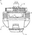
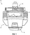
- FIG. 1shows a rotating sprinkler assembly including a sprinkler body of the described embodiments
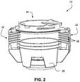
- FIG. 2is a view of the sprinkler body
- FIG. 3is a side view of the sprinkler body
- FIG. 4is a cross-sectional view through the struts of the sprinkler body.
- FIG. 5shows a rotating sprinkler assembly including the sprinkler body of the described embodiments mounted on a center pivot pipe.
- a rotating sprinkler assembly 10includes a sprinkler body 12 securing a nozzle component 14 , a deflector plate 16 , and a brake assembly 18 .
- waterflows through the nozzle component 14 , which includes a nozzle, and is directed by the nozzle component 14 to the deflector plate 16 .
- the deflector plate 16includes a plurality of grooves and lands that serve to direct water outward from the sprinkler assembly in a predefined spray pattern.
- the structure of the deflector plate 16also causes the deflector plate 16 to rotate when impacted with water under pressure.
- the brake assembly 18serves to attenuate the rotating velocity of the deflector plate 16 .
- FIGS. 2-4show details of the sprinkler body 12 .
- the sprinkler body 12includes a base 20 securable to a source of water under pressure.
- the base 20is securable to a center pivot pipe.
- the base 20secures the nozzle component 14 through which water under pressure flows.
- At least two support struts 22are connected to and extend from the base 20 as shown.
- the support struts 22extend up and over the base 20 and are connected to a deflector plate support 24 .
- the deflector plate support 24is thus disposed spaced from the base 20 by the support struts 22 .
- the deflector plate support 24includes notches and grooves and the like to secure the brake assembly 18 and the deflector plate 16 .
- the deflector plate support 24 , the support struts 22 and the base 20are integrated into a single component, for example by molding.
- the sprinkler body 12includes two support struts 22 positioned on diametric opposite sides of the base 20 (i.e., the support struts 22 may be spaced 180 degrees apart). That is, in some embodiments, the sprinkler body 12 includes only two of the support struts 22 .
- FIG. 4is a cross-sectional view of the sprinkler body 12 through the support struts 22 . As shown, the support struts 22 may be wedge-shaped with an inward-facing apex 26 and two inward-facing surfaces 27 extending outward from the apex 26 .
- the support struts 22may be provided with deflection fins 28 on one or both inward-facing surfaces 27 of the wedge-shape.
- the deflection fins 28protrude from the inward-facing surfaces 27 .
- the deflection fins 28are angled downward in a radially outward direction. That is, water that is deflected by the deflector plate 16 and impacts the support struts 22 is directed downward by the deflection fins 28 as the water travels radially outward.
- the deflection fins 28 on one of the two inward-facing surfaces 27 of the support struts 22are symmetrical with the deflection fins 28 on the other of the two inward-facing surfaces.
- FIG. 5shows an exemplary application with the sprinkler assembly 10 secured on a center pivot pipe 30 .
- a pressure regulator 32may be interposed between the center pivot pipe 30 and the rotating sprinkler assembly 10 .
- the sprinkler body 12includes two support struts 22 spaced 180 degrees apart.
- the support struts 22are installed in alignment with a longitudinal axis 34 of the center pivot pipe 30 .
- the support struts 22displace the water from the deflector plate by virtue of the wedge-shape of the support struts 22 , thereby creating a void in the pattern of water spray in line with the center pivot pipe 30 .
- the deflection fins 28 that protrude from each of the two inward-facing surfaces 27 of the support struts 22serve to deflect the water spray, preferably downward.
- the amount of water hitting the pivot pipe that tends to drool off the pivot pipecan be reduced. Additionally, by deflecting the water downward with the deflection fins, water hitting the struts may be deflected toward the ground rather than being blown away with the wind or creating drool from the sprinkler.
Landscapes
- Nozzles (AREA)
Abstract
Description
Claims (15)
Priority Applications (1)
| Application Number | Priority Date | Filing Date | Title |
|---|---|---|---|
| US16/216,042US11154882B2 (en) | 2018-12-11 | 2018-12-11 | Cage design with modified struts including oriented fins |
Applications Claiming Priority (1)
| Application Number | Priority Date | Filing Date | Title |
|---|---|---|---|
| US16/216,042US11154882B2 (en) | 2018-12-11 | 2018-12-11 | Cage design with modified struts including oriented fins |
Publications (2)
| Publication Number | Publication Date |
|---|---|
| US20200179960A1 US20200179960A1 (en) | 2020-06-11 |
| US11154882B2true US11154882B2 (en) | 2021-10-26 |
Family
ID=70970635
Family Applications (1)
| Application Number | Title | Priority Date | Filing Date |
|---|---|---|---|
| US16/216,042Active2039-02-08US11154882B2 (en) | 2018-12-11 | 2018-12-11 | Cage design with modified struts including oriented fins |
Country Status (1)
| Country | Link |
|---|---|
| US (1) | US11154882B2 (en) |
Cited By (1)
| Publication number | Priority date | Publication date | Assignee | Title |
|---|---|---|---|---|
| USD966123S1 (en)* | 2020-02-28 | 2022-10-11 | Nelson Irrigation Corporation | Pressure regulator |
Citations (26)
| Publication number | Priority date | Publication date | Assignee | Title |
|---|---|---|---|---|
| US2488234A (en)* | 1947-05-05 | 1949-11-15 | Murrell E Perry | Spray fluid rotated lawn sprinkler |
| USD258754S (en)* | 1979-07-16 | 1981-03-31 | Addison Carl E | Irrigation spray nozzle |
| US5297737A (en)* | 1993-03-30 | 1994-03-29 | Nelson Irrigation Corporation | Sprinkler frost clip |
| US5372307A (en) | 1993-08-10 | 1994-12-13 | Nelson Irrigation Corporation | Rotary sprinkler stream interrupter |
| US5377914A (en) | 1993-02-03 | 1995-01-03 | Rain Bird Sprinkler Mfg., Corp. | Speed controlled rotating sprinkler |
| US5439174A (en) | 1994-03-15 | 1995-08-08 | Nelson Irrigation Corporation | Nutating sprinkler |
| US5588595A (en) | 1994-03-15 | 1996-12-31 | Nelson Irrigation Corporation | Nutating sprinkler |
| US5671886A (en)* | 1995-08-23 | 1997-09-30 | Nelson Irrigation Corporation | Rotary sprinkler stream interrupter with enhanced emitting stream |
| US5671885A (en) | 1995-12-18 | 1997-09-30 | Nelson Irrigation Corporation | Nutating sprinkler with rotary shaft and seal |
| US5992760A (en) | 1998-08-02 | 1999-11-30 | Virtual Rain, Inc. | Impact sprinkler unit |
| US6607147B2 (en) | 2001-04-03 | 2003-08-19 | Nelson Irrigation Corporation | High volume sprinkler automated arc changer |
| US7100842B2 (en) | 2004-07-07 | 2006-09-05 | Nelson Irrigation Corporation | Two-axis full-circle sprinkler |
| US7287710B1 (en) | 2006-07-21 | 2007-10-30 | Nelson Irrigation Corporation | Sprinkler with magnetic nutating mechanism and related method |
| US7300004B2 (en) | 2003-08-22 | 2007-11-27 | Nelson Irrigation Corporation | Traveling sprinkler incorporating automatic water supply valve docking station |
| US7562833B2 (en) | 2006-07-21 | 2009-07-21 | Nelson Irrigation Corporation | Sprinkler with magnetic nutating mechanism and related method |
| US7603726B2 (en)* | 2005-12-20 | 2009-10-20 | S.C. Johnson & Son, Inc. | Toilet bowl cleaning and/or deodorizing device |
| US7789323B2 (en) | 2008-06-27 | 2010-09-07 | Nelson Irrigation Corporation | Dual-mode sprinkler head |
| US7942345B2 (en) | 2008-08-14 | 2011-05-17 | Nelson Irrigation Corporation | Sprinkler with nutating mechanism and optional weight |
| US7980488B2 (en) | 2006-04-24 | 2011-07-19 | Nelson Irrigation Corporation | Sprinkler with geared viscous hesitator and related method |
| US8028932B2 (en) | 2009-04-01 | 2011-10-04 | Nelson Irrigation Corporation | Sprinkler with nutating mechanism and optional weight |
| US8336788B2 (en) | 2009-08-07 | 2012-12-25 | Nelson Irrigation Corporation | Dripless rotary sprinkler and related method |
| US8567699B2 (en) | 2009-08-05 | 2013-10-29 | Nelson Irrigation Corporation | Rotary strut sprinkler |
| US8991724B2 (en) | 2012-06-06 | 2015-03-31 | Nelson Irrigation Corporation | Wobbling sprinkler with viscous brake |
| US8998107B2 (en) | 2009-07-31 | 2015-04-07 | Nelson Irrigation Corporation | Pop-up sprinkler with integrated pressure regulator and drain check |
| US9095859B2 (en) | 2012-06-01 | 2015-08-04 | Nelson Irrigation Corporation | Multi-nozzle shuttle for a sprinkler head |
| US9700904B2 (en)* | 2014-02-07 | 2017-07-11 | Rain Bird Corporation | Sprinkler |
- 2018
- 2018-12-11USUS16/216,042patent/US11154882B2/enactiveActive
Patent Citations (26)
| Publication number | Priority date | Publication date | Assignee | Title |
|---|---|---|---|---|
| US2488234A (en)* | 1947-05-05 | 1949-11-15 | Murrell E Perry | Spray fluid rotated lawn sprinkler |
| USD258754S (en)* | 1979-07-16 | 1981-03-31 | Addison Carl E | Irrigation spray nozzle |
| US5377914A (en) | 1993-02-03 | 1995-01-03 | Rain Bird Sprinkler Mfg., Corp. | Speed controlled rotating sprinkler |
| US5297737A (en)* | 1993-03-30 | 1994-03-29 | Nelson Irrigation Corporation | Sprinkler frost clip |
| US5372307A (en) | 1993-08-10 | 1994-12-13 | Nelson Irrigation Corporation | Rotary sprinkler stream interrupter |
| US5588595A (en) | 1994-03-15 | 1996-12-31 | Nelson Irrigation Corporation | Nutating sprinkler |
| US5439174A (en) | 1994-03-15 | 1995-08-08 | Nelson Irrigation Corporation | Nutating sprinkler |
| US5671886A (en)* | 1995-08-23 | 1997-09-30 | Nelson Irrigation Corporation | Rotary sprinkler stream interrupter with enhanced emitting stream |
| US5671885A (en) | 1995-12-18 | 1997-09-30 | Nelson Irrigation Corporation | Nutating sprinkler with rotary shaft and seal |
| US5992760A (en) | 1998-08-02 | 1999-11-30 | Virtual Rain, Inc. | Impact sprinkler unit |
| US6607147B2 (en) | 2001-04-03 | 2003-08-19 | Nelson Irrigation Corporation | High volume sprinkler automated arc changer |
| US7300004B2 (en) | 2003-08-22 | 2007-11-27 | Nelson Irrigation Corporation | Traveling sprinkler incorporating automatic water supply valve docking station |
| US7100842B2 (en) | 2004-07-07 | 2006-09-05 | Nelson Irrigation Corporation | Two-axis full-circle sprinkler |
| US7603726B2 (en)* | 2005-12-20 | 2009-10-20 | S.C. Johnson & Son, Inc. | Toilet bowl cleaning and/or deodorizing device |
| US7980488B2 (en) | 2006-04-24 | 2011-07-19 | Nelson Irrigation Corporation | Sprinkler with geared viscous hesitator and related method |
| US7562833B2 (en) | 2006-07-21 | 2009-07-21 | Nelson Irrigation Corporation | Sprinkler with magnetic nutating mechanism and related method |
| US7287710B1 (en) | 2006-07-21 | 2007-10-30 | Nelson Irrigation Corporation | Sprinkler with magnetic nutating mechanism and related method |
| US7789323B2 (en) | 2008-06-27 | 2010-09-07 | Nelson Irrigation Corporation | Dual-mode sprinkler head |
| US7942345B2 (en) | 2008-08-14 | 2011-05-17 | Nelson Irrigation Corporation | Sprinkler with nutating mechanism and optional weight |
| US8028932B2 (en) | 2009-04-01 | 2011-10-04 | Nelson Irrigation Corporation | Sprinkler with nutating mechanism and optional weight |
| US8998107B2 (en) | 2009-07-31 | 2015-04-07 | Nelson Irrigation Corporation | Pop-up sprinkler with integrated pressure regulator and drain check |
| US8567699B2 (en) | 2009-08-05 | 2013-10-29 | Nelson Irrigation Corporation | Rotary strut sprinkler |
| US8336788B2 (en) | 2009-08-07 | 2012-12-25 | Nelson Irrigation Corporation | Dripless rotary sprinkler and related method |
| US9095859B2 (en) | 2012-06-01 | 2015-08-04 | Nelson Irrigation Corporation | Multi-nozzle shuttle for a sprinkler head |
| US8991724B2 (en) | 2012-06-06 | 2015-03-31 | Nelson Irrigation Corporation | Wobbling sprinkler with viscous brake |
| US9700904B2 (en)* | 2014-02-07 | 2017-07-11 | Rain Bird Corporation | Sprinkler |
Cited By (1)
| Publication number | Priority date | Publication date | Assignee | Title |
|---|---|---|---|---|
| USD966123S1 (en)* | 2020-02-28 | 2022-10-11 | Nelson Irrigation Corporation | Pressure regulator |
Also Published As
| Publication number | Publication date |
|---|---|
| US20200179960A1 (en) | 2020-06-11 |
Similar Documents
| Publication | Publication Date | Title |
|---|---|---|
| US4296816A (en) | Horizontal sprinkler deflector with flow lifting formation | |
| US20090078788A1 (en) | Sprinkler Head | |
| US7614457B2 (en) | Sprinkler head with improved flow | |
| US5862994A (en) | Deflector for upright-type fire sprinklers | |
| US2135138A (en) | Automatic sprinkler and deflector therefor | |
| US5865256A (en) | Deflectors for pendent-type fire protection sprinklers | |
| US11154882B2 (en) | Cage design with modified struts including oriented fins | |
| US6182767B1 (en) | Nozzle for a floor nozzle spray system | |
| EP1170059A2 (en) | Nozzle for spraying a surface | |
| US6497543B1 (en) | Aerodynamic resistance weld pin | |
| ES2527522T3 (en) | Splash plate retention method and apparatus | |
| US11213707B2 (en) | Fire suppression sprinkler and deflector | |
| US6920937B2 (en) | Deck/hall extended coverage horizontal sprinkler arrangement | |
| US20160016184A1 (en) | Irrigation sprinkler | |
| ATE300359T1 (en) | SEALANT NOZZLE | |
| CN217391468U (en) | Helicopter apron fire extinguishing system and fire extinguishing nozzle assembly | |
| KR20200010266A (en) | Injection head for liquefied extinguishing agents | |
| US20230285787A1 (en) | Fire protection floor nozzle, systems, and methods for floor nozzle spray systems | |
| US8117820B1 (en) | Jet engine intake deflector system | |
| US20130140379A1 (en) | Sprinkler | |
| US11511144B2 (en) | Sprinkler head | |
| US7278606B2 (en) | Helicopter having a fusilage section and a tail section coupled thereto | |
| US599330A (en) | Fiee extinguished | |
| CN105750130B (en) | A kind of boundling sprayer unit | |
| AU2012100324A4 (en) | A streamlined support element for a sprinkler |
Legal Events
| Date | Code | Title | Description |
|---|---|---|---|
| AS | Assignment | Owner name:NELSON IRRIGATION CORPORATION, WASHINGTON Free format text:ASSIGNMENT OF ASSIGNORS INTEREST;ASSIGNORS:NELSON, CRAIG B.;HELLIE, ANDREW B.;SCOTT, SEAN M.;SIGNING DATES FROM 20181130 TO 20181203;REEL/FRAME:047741/0357 | |
| FEPP | Fee payment procedure | Free format text:ENTITY STATUS SET TO UNDISCOUNTED (ORIGINAL EVENT CODE: BIG.); ENTITY STATUS OF PATENT OWNER: SMALL ENTITY | |
| FEPP | Fee payment procedure | Free format text:ENTITY STATUS SET TO SMALL (ORIGINAL EVENT CODE: SMAL); ENTITY STATUS OF PATENT OWNER: SMALL ENTITY | |
| STPP | Information on status: patent application and granting procedure in general | Free format text:RESPONSE TO NON-FINAL OFFICE ACTION ENTERED AND FORWARDED TO EXAMINER | |
| STPP | Information on status: patent application and granting procedure in general | Free format text:FINAL REJECTION MAILED | |
| STPP | Information on status: patent application and granting procedure in general | Free format text:DOCKETED NEW CASE - READY FOR EXAMINATION | |
| STPP | Information on status: patent application and granting procedure in general | Free format text:NON FINAL ACTION MAILED | |
| STPP | Information on status: patent application and granting procedure in general | Free format text:RESPONSE TO NON-FINAL OFFICE ACTION ENTERED AND FORWARDED TO EXAMINER | |
| STPP | Information on status: patent application and granting procedure in general | Free format text:NOTICE OF ALLOWANCE MAILED -- APPLICATION RECEIVED IN OFFICE OF PUBLICATIONS | |
| STPP | Information on status: patent application and granting procedure in general | Free format text:PUBLICATIONS -- ISSUE FEE PAYMENT VERIFIED | |
| STCF | Information on status: patent grant | Free format text:PATENTED CASE | |
| FEPP | Fee payment procedure | Free format text:MAINTENANCE FEE REMINDER MAILED (ORIGINAL EVENT CODE: REM.); ENTITY STATUS OF PATENT OWNER: SMALL ENTITY |