US11154397B2 - Jacket for surgical heart valve - Google Patents
Jacket for surgical heart valveDownload PDFInfo
- Publication number
- US11154397B2 US11154397B2US16/129,677US201816129677AUS11154397B2US 11154397 B2US11154397 B2US 11154397B2US 201816129677 AUS201816129677 AUS 201816129677AUS 11154397 B2US11154397 B2US 11154397B2
- Authority
- US
- United States
- Prior art keywords
- jacket
- prosthetic valve
- frame
- leaflets
- leaflet
- Prior art date
- Legal status (The legal status is an assumption and is not a legal conclusion. Google has not performed a legal analysis and makes no representation as to the accuracy of the status listed.)
- Active, expires
Links
- 210000003709heart valveAnatomy0.000titleclaimsdescription10
- 238000009958sewingMethods0.000claimsdescription84
- 239000000463materialSubstances0.000claimsdescription53
- 229920001577copolymerPolymers0.000claimsdescription29
- 208000007536ThrombosisDiseases0.000claimsdescription25
- 230000007704transitionEffects0.000claimsdescription22
- 229920001296polysiloxanePolymers0.000claimsdescription15
- 229920002313fluoropolymerPolymers0.000claimsdescription14
- 239000004811fluoropolymerSubstances0.000claimsdescription14
- 230000017531blood circulationEffects0.000claimsdescription11
- 239000000853adhesiveSubstances0.000claimsdescription6
- 230000001070adhesive effectEffects0.000claimsdescription6
- 229920005570flexible polymerPolymers0.000claimsdescription4
- 230000004048modificationEffects0.000claimsdescription4
- 238000012986modificationMethods0.000claimsdescription4
- 238000000034methodMethods0.000abstractdescription40
- 238000000465mouldingMethods0.000description31
- 239000008280bloodSubstances0.000description29
- 210000004369bloodAnatomy0.000description29
- 230000008569processEffects0.000description22
- 230000015572biosynthetic processEffects0.000description21
- 239000013536elastomeric materialSubstances0.000description20
- BFKJFAAPBSQJPD-UHFFFAOYSA-NtetrafluoroetheneChemical groupFC(F)=C(F)FBFKJFAAPBSQJPD-UHFFFAOYSA-N0.000description18
- 239000012528membraneSubstances0.000description17
- 229920000295expanded polytetrafluoroethylenePolymers0.000description16
- 230000008878couplingEffects0.000description15
- 238000010168coupling processMethods0.000description15
- 238000005859coupling reactionMethods0.000description15
- BLTXWCKMNMYXEA-UHFFFAOYSA-N1,1,2-trifluoro-2-(trifluoromethoxy)etheneChemical compoundFC(F)=C(F)OC(F)(F)FBLTXWCKMNMYXEA-UHFFFAOYSA-N0.000description14
- 229920001971elastomerPolymers0.000description13
- 239000000806elastomerSubstances0.000description13
- 229920000642polymerPolymers0.000description13
- 239000002131composite materialSubstances0.000description11
- 239000000306componentSubstances0.000description9
- 230000014759maintenance of locationEffects0.000description9
- 239000004696Poly ether ether ketoneSubstances0.000description7
- 229920002530polyetherether ketonePolymers0.000description7
- 239000011148porous materialSubstances0.000description7
- 239000004812Fluorinated ethylene propyleneSubstances0.000description6
- -1but not limited toSubstances0.000description6
- 239000000203mixtureSubstances0.000description6
- 229920009441perflouroethylene propylenePolymers0.000description6
- 229920001343polytetrafluoroethylenePolymers0.000description6
- 239000004810polytetrafluoroethyleneSubstances0.000description6
- 230000008859changeEffects0.000description5
- 239000012530fluidSubstances0.000description5
- 238000004519manufacturing processMethods0.000description5
- 230000035755proliferationEffects0.000description5
- 229920001059synthetic polymerPolymers0.000description5
- 229920001169thermoplasticPolymers0.000description5
- 150000003673urethanesChemical class0.000description5
- 208000012868OvergrowthDiseases0.000description4
- PPBRXRYQALVLMV-UHFFFAOYSA-NStyreneChemical compoundC=CC1=CC=CC=C1PPBRXRYQALVLMV-UHFFFAOYSA-N0.000description4
- 238000000576coating methodMethods0.000description4
- 230000000295complement effectEffects0.000description4
- 230000003134recirculating effectEffects0.000description4
- 230000004044responseEffects0.000description4
- 229920001187thermosetting polymerPolymers0.000description4
- 239000004416thermosoftening plasticSubstances0.000description4
- 239000000560biocompatible materialSubstances0.000description3
- 238000005520cutting processMethods0.000description3
- 239000003814drugSubstances0.000description3
- 230000006870functionEffects0.000description3
- 229910052751metalInorganic materials0.000description3
- 239000002184metalSubstances0.000description3
- 229920000728polyesterPolymers0.000description3
- 230000002062proliferating effectEffects0.000description3
- 238000011084recoveryMethods0.000description3
- 229910001220stainless steelInorganic materials0.000description3
- 239000010935stainless steelSubstances0.000description3
- 230000008467tissue growthEffects0.000description3
- 238000012800visualizationMethods0.000description3
- 239000004215Carbon black (E152)Substances0.000description2
- 241000545744HirudineaSpecies0.000description2
- 239000004677NylonSubstances0.000description2
- 239000004687Nylon copolymerSubstances0.000description2
- 239000004642PolyimideSubstances0.000description2
- 229920002367PolyisobutenePolymers0.000description2
- RTAQQCXQSZGOHL-UHFFFAOYSA-NTitaniumChemical compound[Ti]RTAQQCXQSZGOHL-UHFFFAOYSA-N0.000description2
- 210000001015abdomenAnatomy0.000description2
- 230000004888barrier functionEffects0.000description2
- 230000009286beneficial effectEffects0.000description2
- 229920000249biocompatible polymerPolymers0.000description2
- 210000004204blood vesselAnatomy0.000description2
- 230000000747cardiac effectEffects0.000description2
- 239000011248coating agentSubstances0.000description2
- 230000003247decreasing effectEffects0.000description2
- 238000000280densificationMethods0.000description2
- 229940079593drugDrugs0.000description2
- HQQADJVZYDDRJT-UHFFFAOYSA-Nethene;prop-1-eneChemical groupC=C.CC=CHQQADJVZYDDRJT-UHFFFAOYSA-N0.000description2
- FHTQCUNSKSWOHF-UHFFFAOYSA-Nethyl carbamate;siliconChemical compound[Si].CCOC(N)=OFHTQCUNSKSWOHF-UHFFFAOYSA-N0.000description2
- 238000010438heat treatmentMethods0.000description2
- 229930195733hydrocarbonNatural products0.000description2
- 150000002430hydrocarbonsChemical class0.000description2
- 239000007943implantSubstances0.000description2
- 238000001746injection mouldingMethods0.000description2
- 238000003698laser cuttingMethods0.000description2
- 230000007774longtermEffects0.000description2
- 150000002739metalsChemical class0.000description2
- 229920001778nylonPolymers0.000description2
- 229920001721polyimidePolymers0.000description2
- 239000002861polymer materialSubstances0.000description2
- 229920002689polyvinyl acetatePolymers0.000description2
- 239000011118polyvinyl acetateSubstances0.000description2
- 230000002787reinforcementEffects0.000description2
- 239000010936titaniumSubstances0.000description2
- 229910052719titaniumInorganic materials0.000description2
- 241000283690Bos taurusSpecies0.000description1
- 241001465754MetazoaSpecies0.000description1
- 241000237503PectinidaeSpecies0.000description1
- 239000004698PolyethyleneSubstances0.000description1
- 230000008901benefitEffects0.000description1
- 230000000903blocking effectEffects0.000description1
- 239000012503blood componentSubstances0.000description1
- 238000005266castingMethods0.000description1
- 230000000694effectsEffects0.000description1
- 239000004744fabricSubstances0.000description1
- 239000000945fillerSubstances0.000description1
- 229920001519homopolymerPolymers0.000description1
- 238000002513implantationMethods0.000description1
- 238000011065in-situ storageMethods0.000description1
- 229910001026inconelInorganic materials0.000description1
- 230000008595infiltrationEffects0.000description1
- 238000001764infiltrationMethods0.000description1
- 238000002347injectionMethods0.000description1
- 239000007924injectionSubstances0.000description1
- 239000011256inorganic fillerSubstances0.000description1
- 229910003475inorganic fillerInorganic materials0.000description1
- 239000011159matrix materialSubstances0.000description1
- 229920002529medical grade siliconePolymers0.000description1
- 230000003278mimic effectEffects0.000description1
- 238000002156mixingMethods0.000description1
- 239000005445natural materialSubstances0.000description1
- 230000035515penetrationEffects0.000description1
- 229920001652poly(etherketoneketone)Polymers0.000description1
- 229920000573polyethylenePolymers0.000description1
- 238000007639printingMethods0.000description1
- 230000008439repair processEffects0.000description1
- 230000000717retained effectEffects0.000description1
- 235000020637scallopNutrition0.000description1
- 238000000926separation methodMethods0.000description1
- 239000007787solidSubstances0.000description1
- 239000002904solventSubstances0.000description1
- 229920002994synthetic fiberPolymers0.000description1
- 229940124597therapeutic agentDrugs0.000description1
- 210000002073venous valveAnatomy0.000description1
- 239000011800void materialSubstances0.000description1
- 238000005406washingMethods0.000description1
Images


Classifications
- A—HUMAN NECESSITIES
- A61—MEDICAL OR VETERINARY SCIENCE; HYGIENE
- A61F—FILTERS IMPLANTABLE INTO BLOOD VESSELS; PROSTHESES; DEVICES PROVIDING PATENCY TO, OR PREVENTING COLLAPSING OF, TUBULAR STRUCTURES OF THE BODY, e.g. STENTS; ORTHOPAEDIC, NURSING OR CONTRACEPTIVE DEVICES; FOMENTATION; TREATMENT OR PROTECTION OF EYES OR EARS; BANDAGES, DRESSINGS OR ABSORBENT PADS; FIRST-AID KITS
- A61F2/00—Filters implantable into blood vessels; Prostheses, i.e. artificial substitutes or replacements for parts of the body; Appliances for connecting them with the body; Devices providing patency to, or preventing collapsing of, tubular structures of the body, e.g. stents
- A61F2/02—Prostheses implantable into the body
- A61F2/24—Heart valves ; Vascular valves, e.g. venous valves; Heart implants, e.g. passive devices for improving the function of the native valve or the heart muscle; Transmyocardial revascularisation [TMR] devices; Valves implantable in the body
- A61F2/2412—Heart valves ; Vascular valves, e.g. venous valves; Heart implants, e.g. passive devices for improving the function of the native valve or the heart muscle; Transmyocardial revascularisation [TMR] devices; Valves implantable in the body with soft flexible valve members, e.g. tissue valves shaped like natural valves
- A61F2/2418—Scaffolds therefor, e.g. support stents
- A—HUMAN NECESSITIES
- A61—MEDICAL OR VETERINARY SCIENCE; HYGIENE
- A61F—FILTERS IMPLANTABLE INTO BLOOD VESSELS; PROSTHESES; DEVICES PROVIDING PATENCY TO, OR PREVENTING COLLAPSING OF, TUBULAR STRUCTURES OF THE BODY, e.g. STENTS; ORTHOPAEDIC, NURSING OR CONTRACEPTIVE DEVICES; FOMENTATION; TREATMENT OR PROTECTION OF EYES OR EARS; BANDAGES, DRESSINGS OR ABSORBENT PADS; FIRST-AID KITS
- A61F2/00—Filters implantable into blood vessels; Prostheses, i.e. artificial substitutes or replacements for parts of the body; Appliances for connecting them with the body; Devices providing patency to, or preventing collapsing of, tubular structures of the body, e.g. stents
- A61F2/02—Prostheses implantable into the body
- A61F2/24—Heart valves ; Vascular valves, e.g. venous valves; Heart implants, e.g. passive devices for improving the function of the native valve or the heart muscle; Transmyocardial revascularisation [TMR] devices; Valves implantable in the body
- A61F2/2409—Support rings therefor, e.g. for connecting valves to tissue
- A—HUMAN NECESSITIES
- A61—MEDICAL OR VETERINARY SCIENCE; HYGIENE
- A61L—METHODS OR APPARATUS FOR STERILISING MATERIALS OR OBJECTS IN GENERAL; DISINFECTION, STERILISATION OR DEODORISATION OF AIR; CHEMICAL ASPECTS OF BANDAGES, DRESSINGS, ABSORBENT PADS OR SURGICAL ARTICLES; MATERIALS FOR BANDAGES, DRESSINGS, ABSORBENT PADS OR SURGICAL ARTICLES
- A61L27/00—Materials for grafts or prostheses or for coating grafts or prostheses
- A61L27/14—Macromolecular materials
- A61L27/16—Macromolecular materials obtained by reactions only involving carbon-to-carbon unsaturated bonds
- A—HUMAN NECESSITIES
- A61—MEDICAL OR VETERINARY SCIENCE; HYGIENE
- A61L—METHODS OR APPARATUS FOR STERILISING MATERIALS OR OBJECTS IN GENERAL; DISINFECTION, STERILISATION OR DEODORISATION OF AIR; CHEMICAL ASPECTS OF BANDAGES, DRESSINGS, ABSORBENT PADS OR SURGICAL ARTICLES; MATERIALS FOR BANDAGES, DRESSINGS, ABSORBENT PADS OR SURGICAL ARTICLES
- A61L27/00—Materials for grafts or prostheses or for coating grafts or prostheses
- A61L27/14—Macromolecular materials
- A61L27/18—Macromolecular materials obtained otherwise than by reactions only involving carbon-to-carbon unsaturated bonds
- C—CHEMISTRY; METALLURGY
- C08—ORGANIC MACROMOLECULAR COMPOUNDS; THEIR PREPARATION OR CHEMICAL WORKING-UP; COMPOSITIONS BASED THEREON
- C08L—COMPOSITIONS OF MACROMOLECULAR COMPOUNDS
- C08L27/00—Compositions of homopolymers or copolymers of compounds having one or more unsaturated aliphatic radicals, each having only one carbon-to-carbon double bond, and at least one being terminated by a halogen; Compositions of derivatives of such polymers
- C08L27/02—Compositions of homopolymers or copolymers of compounds having one or more unsaturated aliphatic radicals, each having only one carbon-to-carbon double bond, and at least one being terminated by a halogen; Compositions of derivatives of such polymers not modified by chemical after-treatment
- C08L27/12—Compositions of homopolymers or copolymers of compounds having one or more unsaturated aliphatic radicals, each having only one carbon-to-carbon double bond, and at least one being terminated by a halogen; Compositions of derivatives of such polymers not modified by chemical after-treatment containing fluorine atoms
- C08L27/18—Homopolymers or copolymers or tetrafluoroethene
- C—CHEMISTRY; METALLURGY
- C08—ORGANIC MACROMOLECULAR COMPOUNDS; THEIR PREPARATION OR CHEMICAL WORKING-UP; COMPOSITIONS BASED THEREON
- C08L—COMPOSITIONS OF MACROMOLECULAR COMPOUNDS
- C08L83/00—Compositions of macromolecular compounds obtained by reactions forming in the main chain of the macromolecule a linkage containing silicon with or without sulfur, nitrogen, oxygen or carbon only; Compositions of derivatives of such polymers
- C08L83/04—Polysiloxanes
- A—HUMAN NECESSITIES
- A61—MEDICAL OR VETERINARY SCIENCE; HYGIENE
- A61F—FILTERS IMPLANTABLE INTO BLOOD VESSELS; PROSTHESES; DEVICES PROVIDING PATENCY TO, OR PREVENTING COLLAPSING OF, TUBULAR STRUCTURES OF THE BODY, e.g. STENTS; ORTHOPAEDIC, NURSING OR CONTRACEPTIVE DEVICES; FOMENTATION; TREATMENT OR PROTECTION OF EYES OR EARS; BANDAGES, DRESSINGS OR ABSORBENT PADS; FIRST-AID KITS
- A61F2/00—Filters implantable into blood vessels; Prostheses, i.e. artificial substitutes or replacements for parts of the body; Appliances for connecting them with the body; Devices providing patency to, or preventing collapsing of, tubular structures of the body, e.g. stents
- A61F2/02—Prostheses implantable into the body
- A61F2/24—Heart valves ; Vascular valves, e.g. venous valves; Heart implants, e.g. passive devices for improving the function of the native valve or the heart muscle; Transmyocardial revascularisation [TMR] devices; Valves implantable in the body
- A61F2/2412—Heart valves ; Vascular valves, e.g. venous valves; Heart implants, e.g. passive devices for improving the function of the native valve or the heart muscle; Transmyocardial revascularisation [TMR] devices; Valves implantable in the body with soft flexible valve members, e.g. tissue valves shaped like natural valves
- A61F2/2415—Manufacturing methods
- A—HUMAN NECESSITIES
- A61—MEDICAL OR VETERINARY SCIENCE; HYGIENE
- A61F—FILTERS IMPLANTABLE INTO BLOOD VESSELS; PROSTHESES; DEVICES PROVIDING PATENCY TO, OR PREVENTING COLLAPSING OF, TUBULAR STRUCTURES OF THE BODY, e.g. STENTS; ORTHOPAEDIC, NURSING OR CONTRACEPTIVE DEVICES; FOMENTATION; TREATMENT OR PROTECTION OF EYES OR EARS; BANDAGES, DRESSINGS OR ABSORBENT PADS; FIRST-AID KITS
- A61F2/00—Filters implantable into blood vessels; Prostheses, i.e. artificial substitutes or replacements for parts of the body; Appliances for connecting them with the body; Devices providing patency to, or preventing collapsing of, tubular structures of the body, e.g. stents
- A61F2/02—Prostheses implantable into the body
- A61F2/24—Heart valves ; Vascular valves, e.g. venous valves; Heart implants, e.g. passive devices for improving the function of the native valve or the heart muscle; Transmyocardial revascularisation [TMR] devices; Valves implantable in the body
- A61F2/2427—Devices for manipulating or deploying heart valves during implantation
- A—HUMAN NECESSITIES
- A61—MEDICAL OR VETERINARY SCIENCE; HYGIENE
- A61F—FILTERS IMPLANTABLE INTO BLOOD VESSELS; PROSTHESES; DEVICES PROVIDING PATENCY TO, OR PREVENTING COLLAPSING OF, TUBULAR STRUCTURES OF THE BODY, e.g. STENTS; ORTHOPAEDIC, NURSING OR CONTRACEPTIVE DEVICES; FOMENTATION; TREATMENT OR PROTECTION OF EYES OR EARS; BANDAGES, DRESSINGS OR ABSORBENT PADS; FIRST-AID KITS
- A61F2210/00—Particular material properties of prostheses classified in groups A61F2/00 - A61F2/26 or A61F2/82 or A61F9/00 or A61F11/00 or subgroups thereof
- A61F2210/0076—Particular material properties of prostheses classified in groups A61F2/00 - A61F2/26 or A61F2/82 or A61F9/00 or A61F11/00 or subgroups thereof multilayered, e.g. laminated structures
- A—HUMAN NECESSITIES
- A61—MEDICAL OR VETERINARY SCIENCE; HYGIENE
- A61F—FILTERS IMPLANTABLE INTO BLOOD VESSELS; PROSTHESES; DEVICES PROVIDING PATENCY TO, OR PREVENTING COLLAPSING OF, TUBULAR STRUCTURES OF THE BODY, e.g. STENTS; ORTHOPAEDIC, NURSING OR CONTRACEPTIVE DEVICES; FOMENTATION; TREATMENT OR PROTECTION OF EYES OR EARS; BANDAGES, DRESSINGS OR ABSORBENT PADS; FIRST-AID KITS
- A61F2220/00—Fixations or connections for prostheses classified in groups A61F2/00 - A61F2/26 or A61F2/82 or A61F9/00 or A61F11/00 or subgroups thereof
- A61F2220/0008—Fixation appliances for connecting prostheses to the body
- A—HUMAN NECESSITIES
- A61—MEDICAL OR VETERINARY SCIENCE; HYGIENE
- A61F—FILTERS IMPLANTABLE INTO BLOOD VESSELS; PROSTHESES; DEVICES PROVIDING PATENCY TO, OR PREVENTING COLLAPSING OF, TUBULAR STRUCTURES OF THE BODY, e.g. STENTS; ORTHOPAEDIC, NURSING OR CONTRACEPTIVE DEVICES; FOMENTATION; TREATMENT OR PROTECTION OF EYES OR EARS; BANDAGES, DRESSINGS OR ABSORBENT PADS; FIRST-AID KITS
- A61F2220/00—Fixations or connections for prostheses classified in groups A61F2/00 - A61F2/26 or A61F2/82 or A61F9/00 or A61F11/00 or subgroups thereof
- A61F2220/0025—Connections or couplings between prosthetic parts, e.g. between modular parts; Connecting elements
- A61F2220/0033—Connections or couplings between prosthetic parts, e.g. between modular parts; Connecting elements made by longitudinally pushing a protrusion into a complementary-shaped recess, e.g. held by friction fit
- A—HUMAN NECESSITIES
- A61—MEDICAL OR VETERINARY SCIENCE; HYGIENE
- A61F—FILTERS IMPLANTABLE INTO BLOOD VESSELS; PROSTHESES; DEVICES PROVIDING PATENCY TO, OR PREVENTING COLLAPSING OF, TUBULAR STRUCTURES OF THE BODY, e.g. STENTS; ORTHOPAEDIC, NURSING OR CONTRACEPTIVE DEVICES; FOMENTATION; TREATMENT OR PROTECTION OF EYES OR EARS; BANDAGES, DRESSINGS OR ABSORBENT PADS; FIRST-AID KITS
- A61F2220/00—Fixations or connections for prostheses classified in groups A61F2/00 - A61F2/26 or A61F2/82 or A61F9/00 or A61F11/00 or subgroups thereof
- A61F2220/0025—Connections or couplings between prosthetic parts, e.g. between modular parts; Connecting elements
- A61F2220/0041—Connections or couplings between prosthetic parts, e.g. between modular parts; Connecting elements using additional screws, bolts, dowels or rivets, e.g. connecting screws
- A—HUMAN NECESSITIES
- A61—MEDICAL OR VETERINARY SCIENCE; HYGIENE
- A61F—FILTERS IMPLANTABLE INTO BLOOD VESSELS; PROSTHESES; DEVICES PROVIDING PATENCY TO, OR PREVENTING COLLAPSING OF, TUBULAR STRUCTURES OF THE BODY, e.g. STENTS; ORTHOPAEDIC, NURSING OR CONTRACEPTIVE DEVICES; FOMENTATION; TREATMENT OR PROTECTION OF EYES OR EARS; BANDAGES, DRESSINGS OR ABSORBENT PADS; FIRST-AID KITS
- A61F2220/00—Fixations or connections for prostheses classified in groups A61F2/00 - A61F2/26 or A61F2/82 or A61F9/00 or A61F11/00 or subgroups thereof
- A61F2220/0025—Connections or couplings between prosthetic parts, e.g. between modular parts; Connecting elements
- A61F2220/005—Connections or couplings between prosthetic parts, e.g. between modular parts; Connecting elements using adhesives
- A—HUMAN NECESSITIES
- A61—MEDICAL OR VETERINARY SCIENCE; HYGIENE
- A61F—FILTERS IMPLANTABLE INTO BLOOD VESSELS; PROSTHESES; DEVICES PROVIDING PATENCY TO, OR PREVENTING COLLAPSING OF, TUBULAR STRUCTURES OF THE BODY, e.g. STENTS; ORTHOPAEDIC, NURSING OR CONTRACEPTIVE DEVICES; FOMENTATION; TREATMENT OR PROTECTION OF EYES OR EARS; BANDAGES, DRESSINGS OR ABSORBENT PADS; FIRST-AID KITS
- A61F2220/00—Fixations or connections for prostheses classified in groups A61F2/00 - A61F2/26 or A61F2/82 or A61F9/00 or A61F11/00 or subgroups thereof
- A61F2220/0025—Connections or couplings between prosthetic parts, e.g. between modular parts; Connecting elements
- A61F2220/0075—Connections or couplings between prosthetic parts, e.g. between modular parts; Connecting elements sutured, ligatured or stitched, retained or tied with a rope, string, thread, wire or cable
- A—HUMAN NECESSITIES
- A61—MEDICAL OR VETERINARY SCIENCE; HYGIENE
- A61F—FILTERS IMPLANTABLE INTO BLOOD VESSELS; PROSTHESES; DEVICES PROVIDING PATENCY TO, OR PREVENTING COLLAPSING OF, TUBULAR STRUCTURES OF THE BODY, e.g. STENTS; ORTHOPAEDIC, NURSING OR CONTRACEPTIVE DEVICES; FOMENTATION; TREATMENT OR PROTECTION OF EYES OR EARS; BANDAGES, DRESSINGS OR ABSORBENT PADS; FIRST-AID KITS
- A61F2230/00—Geometry of prostheses classified in groups A61F2/00 - A61F2/26 or A61F2/82 or A61F9/00 or A61F11/00 or subgroups thereof
- A61F2230/0063—Three-dimensional shapes
- A61F2230/0069—Three-dimensional shapes cylindrical
- A—HUMAN NECESSITIES
- A61—MEDICAL OR VETERINARY SCIENCE; HYGIENE
- A61F—FILTERS IMPLANTABLE INTO BLOOD VESSELS; PROSTHESES; DEVICES PROVIDING PATENCY TO, OR PREVENTING COLLAPSING OF, TUBULAR STRUCTURES OF THE BODY, e.g. STENTS; ORTHOPAEDIC, NURSING OR CONTRACEPTIVE DEVICES; FOMENTATION; TREATMENT OR PROTECTION OF EYES OR EARS; BANDAGES, DRESSINGS OR ABSORBENT PADS; FIRST-AID KITS
- A61F2250/00—Special features of prostheses classified in groups A61F2/00 - A61F2/26 or A61F2/82 or A61F9/00 or A61F11/00 or subgroups thereof
- A61F2250/0014—Special features of prostheses classified in groups A61F2/00 - A61F2/26 or A61F2/82 or A61F9/00 or A61F11/00 or subgroups thereof having different values of a given property or geometrical feature, e.g. mechanical property or material property, at different locations within the same prosthesis
- A61F2250/0051—Special features of prostheses classified in groups A61F2/00 - A61F2/26 or A61F2/82 or A61F9/00 or A61F11/00 or subgroups thereof having different values of a given property or geometrical feature, e.g. mechanical property or material property, at different locations within the same prosthesis differing in tissue ingrowth capacity, e.g. made from both ingrowth-promoting and ingrowth-preventing parts
- A—HUMAN NECESSITIES
- A61—MEDICAL OR VETERINARY SCIENCE; HYGIENE
- A61F—FILTERS IMPLANTABLE INTO BLOOD VESSELS; PROSTHESES; DEVICES PROVIDING PATENCY TO, OR PREVENTING COLLAPSING OF, TUBULAR STRUCTURES OF THE BODY, e.g. STENTS; ORTHOPAEDIC, NURSING OR CONTRACEPTIVE DEVICES; FOMENTATION; TREATMENT OR PROTECTION OF EYES OR EARS; BANDAGES, DRESSINGS OR ABSORBENT PADS; FIRST-AID KITS
- A61F2250/00—Special features of prostheses classified in groups A61F2/00 - A61F2/26 or A61F2/82 or A61F9/00 or A61F11/00 or subgroups thereof
- A61F2250/0058—Additional features; Implant or prostheses properties not otherwise provided for
- A61F2250/006—Additional features; Implant or prostheses properties not otherwise provided for modular
- A—HUMAN NECESSITIES
- A61—MEDICAL OR VETERINARY SCIENCE; HYGIENE
- A61F—FILTERS IMPLANTABLE INTO BLOOD VESSELS; PROSTHESES; DEVICES PROVIDING PATENCY TO, OR PREVENTING COLLAPSING OF, TUBULAR STRUCTURES OF THE BODY, e.g. STENTS; ORTHOPAEDIC, NURSING OR CONTRACEPTIVE DEVICES; FOMENTATION; TREATMENT OR PROTECTION OF EYES OR EARS; BANDAGES, DRESSINGS OR ABSORBENT PADS; FIRST-AID KITS
- A61F2250/00—Special features of prostheses classified in groups A61F2/00 - A61F2/26 or A61F2/82 or A61F9/00 or A61F11/00 or subgroups thereof
- A61F2250/0058—Additional features; Implant or prostheses properties not otherwise provided for
- A61F2250/0069—Sealing means
- A—HUMAN NECESSITIES
- A61—MEDICAL OR VETERINARY SCIENCE; HYGIENE
- A61L—METHODS OR APPARATUS FOR STERILISING MATERIALS OR OBJECTS IN GENERAL; DISINFECTION, STERILISATION OR DEODORISATION OF AIR; CHEMICAL ASPECTS OF BANDAGES, DRESSINGS, ABSORBENT PADS OR SURGICAL ARTICLES; MATERIALS FOR BANDAGES, DRESSINGS, ABSORBENT PADS OR SURGICAL ARTICLES
- A61L27/00—Materials for grafts or prostheses or for coating grafts or prostheses
- A61L27/28—Materials for coating prostheses
- A—HUMAN NECESSITIES
- A61—MEDICAL OR VETERINARY SCIENCE; HYGIENE
- A61L—METHODS OR APPARATUS FOR STERILISING MATERIALS OR OBJECTS IN GENERAL; DISINFECTION, STERILISATION OR DEODORISATION OF AIR; CHEMICAL ASPECTS OF BANDAGES, DRESSINGS, ABSORBENT PADS OR SURGICAL ARTICLES; MATERIALS FOR BANDAGES, DRESSINGS, ABSORBENT PADS OR SURGICAL ARTICLES
- A61L27/00—Materials for grafts or prostheses or for coating grafts or prostheses
- A61L27/50—Materials characterised by their function or physical properties, e.g. injectable or lubricating compositions, shape-memory materials, surface modified materials
- A61L27/56—Porous materials, e.g. foams or sponges
Definitions
- the present disclosurerelates generally to heart valve assembles, and more specifically to apparatuses, systems and methods that include a jacket for a heart valve.
- Prosthetic heart valveshave been developed that attempt to mimic the function and performance of a native valve.
- Prosthetic valves with flexible leafletstypically require some means for securing the leaflets to a support structure, such as a leaflet frame.
- Leaflet(s)may be secured to the frame, for example, by suturing or adhesive/thermal bonding.
- the prosthetic valveis typically attached to a human heart with sutures or some other mechanical attachment means (e.g., staples).
- the prosthetic valvemay be sewn to the heart using suture(s) that pass through a sewing cuff attached to the frame.
- the heart valvesincluding the frames, may have imperfections or other aspects (e.g., resulting from the attachment of the leaflet to the frame) that may contribute to undesirable biological events. Accordingly, it would be desirable to resolve the imperfections or other aspects to facilitate performance of the heart valves.
- a prosthetic valveincludes a heart valve having a frame; one or more leaflets attached to the frame; and a jacket surrounding the frame and configured to cover at least one of gaps, spaces, or interfaces in at least one of the frame and interfaces between the frame and the one or more leaflets attached to the frame to enhance the biocompatibility of the heart valve.
- Example 2further to Example 1, the jacket is molded to at least one of the frame and the one or more leaflets.
- Example 3further to Example 2, the one or more leaflets and the jacket are each formed of a first material.
- the first materialcomprises a fluoropolymer.
- the jacketincludes a first portion and a second portion, and the first portion and the second portion are coupled together to join the jacket to the frame.
- the first portionincludes a first connector
- the second portionincludes a second connector
- the first connectorsnaps together with the second connector to join the first portion of the jacket with the second portion of the jacket.
- Example 7further to Example 5, the first portion and the second portion are secured together by at least one of swaging, an adhesive, a screw, and a rivet.
- Example 8further to any one of Examples 1-7, further including a sewing cuff arranged with the frame, wherein the jacket is configured to cover an interface between the sewing cuff and the frame.
- Example 9further to Example 8, the jacket is bonded to the sewing cuff.
- the jacketis configured to avoid thrombosis to enhance the biocompatibility of the frame.
- the jacketis configured to block tissue ingrowth into the one or more leaflets to enhance the biocompatibility of the frame.
- the jacketis configured to promote tissue ingrowth.
- the jacketincludes an outflow edge and a transition between the one or more leaflets and the outflow edge includes a fillet.
- the filletincludes a nonlinear surface.
- Example 15further to Example 13, the fillet extends radially inwardly.
- the first portion of the jacketdefines an outflow side of the prosthetic valve, and wherein a flange extends radially outwardly from the first portion of the jacket.
- a flangeextends radially outwardly from the jacket on an outflow side of the sewing cuff.
- the flangeis longitudinally offset from the sewing cuff.
- the flangeis configured to operate as a tissue ingrowth boundary to help obstruct tissue ingrowth into the one or more leaflets.
- the flangeis positioned between the sewing cuff and an outflow side of the one or more leaflets.
- the jacketis formed of a rigid material.
- the jacketis formed of a TFE-PMVE copolymer.
- a portion of the jacketis formed of a flexible polymer.
- Example 24further to any one of Example 23, wherein the flexible polymer is silicone.
- another portion of the jacketis formed of a rigid material.
- the valvealso includes a conduit and wherein the jacket is coupled to the conduit to form a valved conduit.
- a prosthetic valveincluding: a frame; one or more leaflets attached to the frame to define at least one frame to leaflet interface; and a jacket that encapsulates the at least one frame-to-leaflet interface and is configured to isolate the interface from blood flow.
- the jacketis configured to create tissue ingrowth boundaries.
- the jacketis configured to alter the blood flow.
- the jacketincludes a sewing cuff, and the jacket is bonded to at least one of the frame, the leaflets, and the sewing cuff.
- the jacketis overmolded over the frame.
- the jacketis configured to promote tissue ingrowth.
- the jacketis configured to restrict the tissue ingrowth to the frame without extending onto the one or more leaflets.
- the jacketincludes a surface modification to promote tissue ingrowth.
- the jacketincludes an outflow edge and a transition between the one or more leaflets and the outflow edge includes a fillet.
- the filletincludes a nonlinear surface.
- Example 37further to Example 35, the fillet extends radially inwardly.
- a flangeextends radially outwardly from the jacket on an outflow side of the sewing cuff.
- Example 39further to Example 38, the flange is longitudinally offset from the sewing cuff.
- the flangeis configured to operate as a tissue ingrowth boundary to help obstruct tissue ingrowth into the one or more leaflets.
- the flangeis positioned between the sewing cuff and an outflow side of the one or more leaflets.
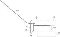
- FIG. 1is an illustration of an example prosthetic valve in accordance with an embodiment
- FIG. 2is an illustration of an example prosthetic valve that includes a sewing cuff in accordance with an embodiment
- FIG. 3Ais a first view of an exploded illustration of an example jacket with a prosthetic valve, in accordance with an embodiment
- FIG. 3Bis a second view of an exploded illustration of the jacket and prosthetic valve shown in FIG. 3A ;
- FIG. 3Cis a third view of an exploded illustration of the jacket and prosthetic valve shown in FIGS. 3A-B ;
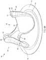
- FIG. 4Ais a first view of an illustration of an example jacket coupled to a prosthetic valve, in accordance with an embodiment
- FIG. 4Bis a second view of an illustration of the jacket and prosthetic valve shown in FIG. 4A ;
- FIG. 4Cis a third view of an illustration of the jacket and prosthetic valve shown in FIGS. 4A-B ;
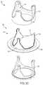
- FIG. 5Ais an illustration of another example jacket coupled to a prosthetic valve, in accordance with an embodiment
- FIG. 5Bshows a close-up view of the jacket and prosthetic valve shown in FIG. 5A ;
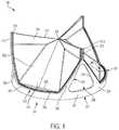
- FIG. 6is an illustration of an example jacket in accordance with an embodiment
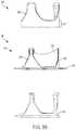
- FIG. 7Ais a schematic cross-sectional illustration of a jacket having a shelf and a prosthetic valve in a closed position, in accordance with an embodiment
- FIG. 7Bis a schematic cross-sectional illustration of the jacket and prosthetic valve, shown in FIG. 7A , in an open position;
- FIGS. 8A and 8Bare first and second views of a jacket, in accordance with an embodiment
- FIG. 9Ais a first view of an illustration of an example jacket coupled to a prosthetic valve, in accordance with an embodiment
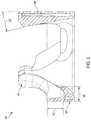
- FIG. 9Bis a cross section view of the example jacket shown in FIG. 9A taken along line 9 B- 9 B of FIG. 9A ;
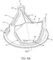
- FIG. 10Ais a first view of an illustration of an example jacket coupled to a prosthetic valve, in accordance with an embodiment
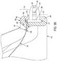
- FIG. 10Bis a cross section view of the example jacket shown in FIG. 10A taken along line 10 B- 10 B of FIG. 10A ;
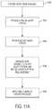
- FIG. 11Ais a flow chart of an example process for making a prosthetic valve, in accordance with an embodiment.
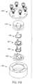
- FIG. 11Bis an exploded view of a mold assembly, in accordance with an embodiment
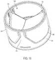
- FIG. 12is a first view of an illustration of an example cuff attachment flange, in accordance with an embodiment
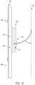
- FIG. 13is a view of an illustration of an example leaflet frame including a keyslot, in accordance with an embodiment
- FIG. 14is a first view of an illustration of another example cuff attachment flange, in accordance with an embodiment
- FIG. 15is a perspective view of an illustration of an example jacket coupled to a prosthetic valve, in accordance with an embodiment
- FIG. 16is a cross-sectional illustration of the jacket and the prosthetic valve shown in FIG. 15 as arranged in a conduit, in accordance with an embodiment
- FIG. 17is a perspective view of an illustration of another example jacket coupled to a prosthetic valve, in accordance with an embodiment
- FIG. 18is a cross-sectional illustration of the jacket and the prosthetic valve shown in FIG. 17 as arranged in a conduit, in accordance with an embodiment
- FIG. 19is a perspective view of an illustration of another example jacket coupled to a prosthetic valve, in accordance with an embodiment
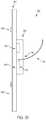
- FIG. 20is a cross-sectional illustration of the jacket and the prosthetic valve shown in FIG. 19 as arranged in a conduit, in accordance with an embodiment
- FIG. 21A-Bare illustrations of a leaflet arranged within the jacket shown in FIGS. 19-20 , in accordance with an embodiment.
- Embodiments hereininclude various apparatus, systems, and methods for a prosthetic valve suitable for surgical and transcatheter placement, such as, but not limited to, cardiac valve replacement.
- the prosthetic valveis operable as a one-way valve wherein the prosthetic valve defines a valve orifice into which leaflets open to permit flow and close so as to occlude the valve orifice and prevent flow in response to differential fluid pressure.
- the prosthetic valvecan include a leaflet frame defining an annular ring and having a leaflet contact surface configured to impart a shape to the leaflet that provides proper function of the valve and one or more leaflet retention surfaces to facilitate leaflet retention to the leaflet frame.
- the leafletsmay be non-sewn, minimally sewn, mechanically coupled, bonded, or non-mechanically coupled to the leaflet frame.
- the valvemay also include a sewing cuff, arranged about the leaflet frame, to provide structure that receives suture for coupling to the implant site.
- the prosthetic valveis wholly synthetic.
- the prosthetic valvemay include one or more drug coatings on one or more portions thereof or may be entirely free of drug coatings.
- interface pointsdue to attachment of leaflets to the frame, attachment of the sewing cuff to the frame, and the frame itself.
- Each aspectmay also include various other interface points or other cracks and crevices.
- the interface points (and cracks and crevices)may cause blood stasis, which can contribute to thrombus formation.
- embodiments hereininclude various apparatus, systems, and methods that include a jacket joined to the frame and configured to enhance the biocompatibility of the frame and lessen the opportunity for thrombus formation.
- the jackets discussed hereincan contribute to manufacturability of the prosthetic valve, to which the jacket is coupled. The jacket can mask manufacturing imperfections and the jacket is also customizable based on patient and need.
- FIG. 1shows an example prosthetic valve 100 in accordance with an embodiment.
- the components of the prosthetic valve 100 that can be observed in FIG. 1include a plurality of leaflets 310 and a leaflet frame 200 that includes a plurality of commissure posts 210 flanked on each side by leaflet window frame element(s) (e.g., two leaflet window sides 223 and a leaflet window base 225 therebetween) that define the leaflet window.
- leaflet window frame element(s)e.g., two leaflet window sides 223 and a leaflet window base 225 therebetween
- Leaflet free edges 312 of the leaflets 310come together at a coaptation region 316 in a Y-shaped pattern to close the prosthetic valve 100 .
- the prosthetic valve 100closes in this fashion when the pressure of the blood on the leaflet outflow side is greater than the pressure of the blood on the leaflet inflow side of the prosthetic valve 100 .
- the leaflet free edges 312 of the leaflets 310move apart to open the prosthetic valve 100 and to let blood flow through the prosthetic valve 100 from the leaflet inflow side when the pressure of the blood on the leaflet inflow side is greater than the pressure on the outflow side.
- the three leaflets 310 of the embodiment of FIG. 1meet or nearly meet at a triple point 348 .
- distalis used in the disclosure to refer to the outflow end (distal end) or outflow direction of a prosthetic valve 100
- proximalis used to refer to the inflow end of a prosthetic valve 100 , or a direction opposite the direction of primary flow through the prosthetic valve 100 .
- the leaflet frame 200is operable to mechanically couple and support the leaflets 310 by way of, at least in part, a plurality of leaflet frame projections 260 ( FIG. 2 ) that are spaced-apart and project from one or more leaflet retention surfaces 233 of the leaflet frame 200 .
- the one or more leaflet retentions surfaces 233are one or more leaflet frame edges, external edges or internal edges, such as a leaflet frame first edge 227 , a leaflet frame second edge 224 , and a leaflet frame internal edges 234 .
- the leaflet frame projections 260are each configured to extend through a leaflet aperture defined by the leaflet 310 .
- the leaflet frame projections 260can have a tenon-like shape.
- the leaflet frame 200may include an annular shape and has a central longitudinal axis.
- the leaflet frame 200comprises a plurality of commissure posts 210 that are spaced from one another. Between two commissure posts 210 is a leaflet window.
- the portion of the leaflet frame 200 disposed adjacent each commissure post 210can be an opening, an open framework, or a continuous wall, which may be further defined in part by the leaflet window sides 223 .
- leaflet frame second edge 224an example of a leaflet frame external edge
- a leaflet retention surface 233can include any leaflet frame surface including, but not limited to, a leaflet frame second edge 224 , a leaflet frame first edge 227 , and/or a leaflet frame internal edge 234 , such as the side internal edge 257 defining triangular opening 256 .
- each of the leaflet windowsare defined by the leaflet frame second edge 224 .
- the leaflet frame second edge 224defines a leaflet frame concavity 240 corresponding to each leaflet window.
- the leaflet frame concavity 240can be curved or angular.
- the shown embodimenthas an angular leaflet frame concavity 240 .
- a set of leaflet frame elements that, along with the commissure post 210 , define each leaflet windoware referred to as leaflet window frame elements.
- a set of leaflet window frame elementscan flank each side of a commissure post 210 .
- the set of leaflet window frame elementscan include two leaflet window sides 223 and a leaflet window base 225 therebetween.
- the leaflet window base 225 and the leaflet window sides 223are configured to couple to and support, along with the commissure posts 210 , each leaflet 310 around the perimeter thereof except for the leaflet free edge 312 .
- the commissure post 210extends from an apex 232 in the outflow direction that is formed at the convergence between two leaflet window sides 223 of adjacent leaflet windows.
- the extent of leaflet attachment along the commissure post 210can affect the leaflet free edge 312 so as to create a narrower or wider coaptation region 316 between the adjacent leaflet free edges 312 where the extent is less or more, respectively. It is also understood that the shape of the leaflet free edge 312 and dimensions of the leaflet belly region 322 influence wider or narrower coaptation.
- the leaflet frame 200defines an annular shape having a leaflet frame inner surface and a leaflet frame outer surface 204 opposite the leaflet frame inner surface. Further, the leaflet frame 200 has a leaflet frame first edge 227 and a leaflet frame second edge 224 opposite the leaflet frame first edge 227 . As discussed further below, the leaflet frame 200 may include a cuff attachment flange 201 ( FIGS. 96,106, 12, and 14 ) that couples adjacent to the leaflet frame first edge 227 so as to project laterally from the leaflet frame outer surface 204 .
- the cuff attachment flange 201may be made of any suitable material including those materials suitable for the leaflet frame 200 discussed herein.
- the cuff attachment flange 201is configured to facilitate coupling of a sewing cuff 285 (discussed further below) to the leaflet frame 200 .
- the cuff attachment flange 201defines an annular ring that is operable to be slidingly received on the leaflet frame outer surface 204 so as to extend circumferentially around a perimeter of the leaflet frame 200 adjacent the leaflet frame first edge 227 .
- the cuff attachment flange 201defines a plurality of spaced apart apertures operable to receive suture therethrough so as to facilitate the coupling of the sewing cuff 285 thereon.
- the cuff attachment flange 201defines a plurality of inwardly projecting spaced apart teeth 205 defining notches 207 therebetween, such that the cuff attachment flange 201 is slidingly received on the leaflet frame outer surface 204 , the inwardly projecting spaced apart teeth 205 cooperates with the leaflet frame outer surface 204 such that the notches 207 in combination with the leaflet frame outer surface 204 define a plurality of apertures operable to receive suture therethrough so as to facilitate coupling of the sewing cuff 285 thereon.
- the cuff attachment flange 201includes one or more inwardly projecting keys 209 operable to be received into a corresponding keyway 101 on the leaflet frame 200 (see FIG. 13 ).
- the key 209is a flange that is operable to be received in the keyway 101 which, is shown as a slot in FIG. 13 .
- the cuff attachment flange 201is slidingly received onto the leaflet frame 200 at the leaflet frame first edge 227 with each key 209 being received within a corresponding keyway 101 .
- the cooperation between the key 209 and the keyway 101may be such that the cuff attachment flange 201 may be “snap fit” onto the leaflet frame 200 and fixed thereto.
- one or more of the keys 209is welded to the leaflet frame 200 adjacent the keyway 101 so as to couple the cuff attachment flange 201 to the leaflet frame 200 .
- each key 209includes a plurality of apertures 203 which, after the key 209 is received into the keyway 101 , presents the apertures 203 adjacent the leaflet frame outer surface 204 so as to receive suture therethrough so as to facilitate coupling of the sewing cuff 285 thereon.
- the cuff attachment flange 201may be made according to known methods, including laser cutting, molding, stamping, or other known processes.
- the cuff attachment flange 201after being slidingly received on the leaflet frame 200 , may be welded to the leaflet frame 200 , fixing the cuff attachment flange 201 to the leaflet frame 200 .
- the cuff attachment flange 201may be integral with the leaflet frame 200 .
- Two ends of the sewing cuff 285are received and coupled to either side of the cuff attachment flange 201 by passing suture through the two ends of the sewing cuff and through the apertures formed in the cuff attachment flange 201 or defined between the cuff attachment flange 201 and the leaflet frame outer surface 204 , as mentioned above.
- the leaflet frame first edge 227 and the cuff attachment flange 201define a planar circumference, as shown in FIGS. 9B and 10B . In other examples, the leaflet frame first edge 227 and the cuff attachment flange 201 define a corresponding non-planar circumference (also referred to as a coronet shape).
- the leaflet frame first edge 227 and the cuff attachment flange 201define a plurality of scallops, or out of plane curves, that are operable to present the sewing cuff 285 , which will take a complementary shape when received onto and coupled to the cuff attachment flange 201 , to a native valve annulus that has a corresponding non-planar circumference (coronet shape).
- the sewing cuff insert 287also has a complementary circumference so as to further shape the sewing cuff 285 .
- the sewing ring insertis composed of medical grade silicone.
- the sewing ring insertmay be pre-formed, such as into an annular shape or a shape otherwise corresponding to one or more of the leaflet frame 200 , the cuff attachment flange 201 and the sewing cuff 285 , or may be injected into the sewing cuff 285 in a non-solid form.
- the sewing insertprovides internal support to the sewing ring.
- the sewing inserthelps seal needle and suture penetrations through the sewing cuff 285 made during implantation.
- each commissure post 210has a post outer side 212 and a post inner side 214 opposite the post outer side 212 . Further, each commissure post 210 has two post lateral sides 213 that are opposite each other and extending between the post inner side 214 and the post outer side 212 such that all sides, namely, the post outer side 212 , the two post lateral sides 213 , and the post inner side 214 , define a perimeter of each commissure post 210 .
- the leaflet frame 200is annular about a central longitudinal axis of the prosthetic valve 100 as shown in FIG. 1 .
- the leaflet frame 200defines three leaflet windows.
- a leaflet window base 225is flanked on each side by two leaflet window sides 223 that together define three sides of an arced isosceles trapezoid, wherein the leaflet frame second edge 224 at the leaflet window base 225 is substantially flat.
- the leaflet attachment regionis coupled to the leaflet window base 225 , each of the two leaflet window sides 223 , and the commissure posts 210 .
- the commissure posts 210can be equally spaced from one another around the leaflet frame 200 .
- the portion of the leaflet frame 200 that is disposed under each commissure post 210 and between adjacent leaflet windowsis a framed triangular opening 256 defined by leaflet frame internal edges 234 of neighboring leaflet window sides 223 and the leaflet frame base. While the triangular opening 256 is shown as open, it can be capped or sealed in various embodiments.
- FIG. 14is a first view of an illustration of another example cuff attachment flange 201 , in accordance with an embodiment.
- the leaflet frame 200may include a cuff attachment flange 201 .
- the cuff attachment flange 201may be made of any suitable material including those materials suitable for the leaflet frame 200 discussed herein.
- the cuff attachment flange 201is configured to facilitate coupling of a sewing cuff 285 to the leaflet frame 200 .
- the cuff attachment flange 201defines an annular ring that is operable to be received on the leaflet frame outer surface 204 so as to extend circumferentially around a perimeter of the leaflet frame 200 .
- the cuff attachment flange 201may include a split-portion 1402 that facilitates placement of the cuff attachment flange 201 about the perimeter of the leaflet frame 200 .
- the split-portion 1402may allow for separation of the cuff attachment flange 201 to place the cuff attachment flange 201 about the perimeter of the leaflet frame 200 .
- the cuff attachment flange 201defines a plurality of spaced apart apertures operable to receive suture therethrough so as to facilitate the coupling of the sewing cuff 285 thereon.
- the cuff attachment flange 201includes one or more inwardly projecting keys 209 operable to be received into a corresponding keyway 101 on the leaflet frame 200 (see FIG. 13 ).
- the key 209is a flange that is operable to be received in the keyway 101 which, is shown as a slot in FIG. 13 .
- the cuff attachment flange 201may separate at the split-portion 1402 and arrange each key 209 received within a corresponding keyway 101 . The cooperation between the key 209 and the keyway 101 may be such that the cuff attachment flange 201 may be “snap fit” onto the leaflet frame 200 and fixed thereto.
- each key 209includes a plurality of apertures 203 which, after the key 209 is received into the keyway 101 , presents the apertures 203 adjacent the leaflet frame outer surface 204 so as to receive suture therethrough so as to facilitate coupling of the sewing cuff 285 thereon.
- the cuff attachment flange 201may be made according to known methods, including laser cutting, molding, stamping, or other known processes.
- FIG. 2shows an example prosthetic valve 100 with a sewing cuff 285 , in accordance with an embodiment.
- the sewing cuff 285is arranged about a leaflet frame 200 in accordance with an embodiment.
- the sewing cuff 285may be arranged about the cuff attachment flange 201 extending radially outwardly from the leaflet frame outer surface 204 of the leaflet frame 200 ( FIGS. 9B and 10B ).
- the sewing cuff 285is operable to provide structure that receives suture for coupling to the implant site.
- the sewing cuff 285may comprise any suitable material, such as, but not limited to, PTFE, ePTFE, double velour polyester, and silicone.
- the sewing cuff 285 materialsmay be in woven or non-woven forms.
- the sewing cuffmay be comprised of an ePTFE fabric.
- the sewing cuff 285may be located circumferentially around a perimeter of the leaflet frame base of the leaflet frame 200 , such as the leaflet frame first edge 227 .
- the sewing cuff 285may comprise a filler material, such as, but not limited to, a silicone ring.
- the sewing ringpermits or promotes tissue ingrowth to help minimize paravalvular leakage.
- the sewing ringadditionally or alternatively helps provide anatomical fixation of the prosthetic valve.
- FIG. 3Ais a first view of an exploded illustration of an example jacket 300 with a prosthetic valve 100 , in accordance with an embodiment.
- the leaflet frame 200includes one or more leaflets 310 attached to the leaflet frame 200 .
- the leaflets 310are attached to the leaflet frame 200 by the plurality of leaflet frame projections 260 .
- the mechanical coupling of the leaflets 310is accomplished by the various aspects of the leaflet frame 200 .
- the leaflet frame 200includes a number of uneven, rough, or not smooth surfaces.
- a jacket 300may be joined to the frame in order to enhance the biocompatibility of the leaflet frame 200 and the prosthetic valve 100 .
- the jacket 300is configured to cover gaps, spaces, interfaces or other structural aspects that are present in the leaflet frame 200 and/or interfaces between the leaflet frame 200 and the one or more leaflets 310 attached to the leaflet frame 200 to enhance the biocompatibility of the leaflet frame 200 .
- the jacket 300additionally helps maintain mechanical attachment of the leaflets 310 to the leaflet frame 200 , including the leaflet frame projections 260 .
- the jacket 300operates as a strain relief for the leaflet 310 . For instance, in some examples, the jacket 300 minimizes the strain of the leaflets 310 at the leaflet frame projections 260 , which helps minimize failures of the leaflets 310 at the leaflet frame projections 260 .
- the jacket 300may be configured to include one or more features or geometries that provide for smooth transitions between the jacket 300 and the leaflet 310 .
- the jacket 300may include one or more fillets at or proximate a transition between the jacket 300 and the leaflet 310 .
- the filletsprovide for a blended interface between the jacket 300 and the leaflets 310 .
- the uneven, rough, or not smooth surfaces in the leaflet frame 200may be present in the leaflet frame 200 itself and/or may be present in the interfaces between aspects of the prosthetic valve 100 .
- the leaflets 310are attached to the frame, and the leaflet frame 200 may also include a sewing cuff 285 .
- Micro or macroscopic interfacesare present between the leaflet frame 200 and the leaflets 310 and the leaflet frame 200 and the sewing cuff 285 .
- the interfaces, cracks, crevices, and other structural aspectsmay contribute to thrombus formation when the prosthetic valve 100 is implanted. These structural aspects, for example, can contribute to stagnate blood regions. Stagnate blood regions negatively affect biocompatibility as the stasis can contribute to thrombus formation.
- the jacket 300enhances the biocompatibility of the leaflet frame 200 by covering, wrapping, or hiding the interfaces, cracks, crevices, other structural aspects, and can also optimize blood flow.
- the jacket 300includes a first portion 302 (an outflow jacket portion) and a second portion 304 (an inflow jacket portion). As shown in FIG. 3A , the first portion 302 of the jacket 300 includes an outflow jacket height 410 and the second portion 304 of the jacket 300 includes an inflow jacket height 412 .
- FIG. 3Bis a second view of an exploded illustration of the jacket 300 and prosthetic valve 100 shown in FIG. 3A
- FIG. 3Cis a third view of an exploded illustration of the jacket 300 and prosthetic valve 100 shown in FIGS. 3A-B
- the first portion 302 and the second portion 304are configured to couple together to form the jacket 300 around the frame.
- the first portion 302 and the second portion 304 together around the frameis shown in further detail in FIGS. 4A-C .
- the first portion 302 and the second portion 304are secured together by at least one of swaging, a snap fit, a click fit, one or more staples, tape, adhesives, one or more screws, one or more rivets, insert molding or overmolding.
- Each of the outflow jacket height 410 and/or the inflow jacket height 412may be altered based on the specific need of the jacket 300 .
- the outflow jacket height 410 and the inflow jacket height 412may be determined by measuring the lowest point in the jacket 300 at which the leaflet 310 attaches.
- the jacket 300can facilitate tissue growth (e.g., tissue ingrowth or tissue overgrowth) relative to the prosthetic valve 100 .
- tissue overgrowthin this context, refers to tissue growing over the leaflet frame 200 and contacting the leaflet 310 , which causes a thrombus response.
- the outflow jacket height 410 and/or the inflow jacket height 412is tailored to avoid ingrowth of tissue onto the leaflets 310 .
- the outflow jacket height 410 and/or the inflow jacket height 412are determined relative to the sewing cuff 285 .
- the outflow jacket height 410 and/or the inflow jacket height 412may be altered, without changing the leaflet frame 200 , in response to patient valve size, position, and/or desired flow characteristics.
- FIG. 4Ais a first view of an illustration of an example jacket 300 coupled to a prosthetic valve 100 , in accordance with an embodiment.
- the jacket 300 shown in FIGS. 4A-Cincludes a first portion 302 and a second portion 304 .
- the first portion 302 and the second portion 304are shown secured together.
- the first portion 302 and the second portion 304are secured about a frame (not shown) of the prosthetic valve 100 .
- the prosthetic valve 100may include a sewing cuff (not shown) arranged with the frame as shown in FIG. 2 .
- the jacket 300is configured to be an interface between the sewing cuff and the frame.
- the jacket 300includes tips 404 (also described as post cover portions) when the first portion 302 and the second portion 304 are joined together.
- the tips 404 , or post cover portionsmay be atraumatic, and may be equal to a number of commissure posts 210 in the prosthetic valve 100 .
- the first portion 302includes first interfaces 406 and the second portion 304 includes second interfaces 408 .
- the first interfaces 406are configured to join with the second interfaces 408 to couple the first portion 302 to the second portion 304 .
- the first interfaces 406 and the second interfaces 408couple together to form the tips 404 of the jacket 300 .
- the first interfaces 406 and the second interfaces 408can snap together to join the first portion 302 to the second portion 304 and form the jacket 300 .
- the jacket 300may be formed of at least one of Polyether ether ketone (PEEK), expanded Polytetrafluoroethylene (ePTFE), Fluorinated ethylene propylene (FEP), copolymers of tetrafluoroethylene (TFE) and perfluoromethyl vinyl ether (PWE) (TFE-PWE copolymer), urethanes, polyimides, thermoplastics, thermosets, 3D printable metals and polymers (stainless steel, titanium, etc.) nylon, or any other biocompatible material suitable for long term blood contact that is dimensionally stable, and does not leech contaminates.
- PEEKPolyether ether ketone
- ePTFEexpanded Polytetrafluoroethylene
- FEPFluorinated ethylene propylene
- TFEtetrafluoroethylene
- PWEperfluoromethyl vinyl ether
- the jacket 300is coupled to or formed about the leaflet frame 200 , in various instances, such that the jacket 300 does not interfere with the leaflets 310 or assist in mechanical fixation of the leaflets 310 to the leaflet frame 200 .
- the jacket 300is configured to cover interfaces, cracks, crevices, and other structural aspects of the prosthetic valve 100 that may contribute to thrombus formation when the prosthetic valve 100 is implanted. And in some instances, as discussed further herein, the jacket 300 is configured to include one or more fillets, which help facilitate smooth transitions between the jacket 300 and the leaflet 310 .
- the jacket 300covers various aspects of the prosthetic valve and includes features and/or geometries, the combination of which operate to help avoid thrombosis (e.g., by reducing cracks, gaps, crevices, and stagnate blood regions) and help enhance the biocompatibility of the leaflet frame 200 and the prosthetic valve 100 .
- FIG. 4Bis a second view of an illustration of the jacket 300 and prosthetic valve 100 shown in FIG. 4A .
- the first portion 302 of the jacket 300includes an outflow jacket height 410 and the second portion 304 of the jacket 300 includes an inflow jacket height 412 .
- the jacket 300can facilitate tissue growth relative to the prosthetic valve 100 .
- tissue overgrowth over the leaflet frame 200can be promoted by the jacket 300 .
- the jacket 300promotes tissue overgrowth to the leaflet 310 .
- the outflow jacket height 410 and/or the inflow jacket height 412are optionally tailored to avoid ingrowth of tissue onto the leaflets 310 , but to promote tissue ingrowth onto the jacket 300 .
- the jacket 300can be configured to create tissue ingrowth boundaries (e.g., ingrowth stops prior to reaching the leaflets 310 ).
- tissue ingrowth boundariese.g., ingrowth stops prior to reaching the leaflets 310 .
- minimizing the outflow jacket height 410helps minimize stagnate blood regions on the outflow side of the leaflets 310 , such as between the leaflets 310 and the outflow jacket portion, which helps minimize thrombus formation.
- minimizing the outflow jacket height 410may increase the potential for surrounding tissue to proliferate radially inwardly across the outflow jacket portion toward the leaflets 310 . That is, decreasing the height of the outflow jacket portion reduces the ability of the outflow jacket portion to operate as a boundary to tissue ingrowth, as tissue may proliferate across the outflow jacket portion, as those of skill should appreciate.
- the jacket 300may include an additional feature that is distinct from the outflow jacket height 410 and that operates to prevent or minimize a potential for tissue to proliferate radially inwardly across the outflow jacket portion.
- the jacket 300may include one or more flange features that project at least partially radially outwardly from the outflow jacket portion ( FIGS. 10A and 10B ). The one or more flange features operate as a boundary to tissue ingrowth and proliferation.
- the jacket 300includes a surface having a property predetermined to permit (or even promote) tissue ingrowth, or having a property predetermined to prevent or minimize tissue ingrowth.
- the surface of the jacket 300may have a texture, such as a relatively rough texture, that is predetermined to permit or promote tissue ingrowth.
- the surface of the jacket 300may have a relatively smooth texture that prevents or minimizes tissue ingrowth.
- the surface of the jacket 300may be modified to achieve the desired surface texture.
- the jacket 300could be formed of a porous PEEK material (injection moldable and/or machined) or a porous PEKK material (3D printable).
- the jacket 300can have a predetermined pore size and density that permits or promotes tissue ingrowth where desired.
- the jacket 300can have non-tissue ingrowth regions.
- at least the pores on the surface of the jacket 300can be imbibed, coated, or infused to prevent or minimize tissue ingrowth on portions of or all of the jacket 300 .
- the pores on the jacket 300may be imbibed with a soluble TFE-PMVE copolymer, and the jacket 300 may be solvent welded to a soluble TFE-PMVE copolymer portion or subcomponent on the leaflets 310 to prevent or minimize tissue ingrowth onto or across the leaflets 310 and the jacket 300 .
- one or more layers of materialsuch as the material of which the jacket is formed, may be bonded (e.g., pre-bonded) to one or more portions of the leaflets 310 independent of the jacket being formed about the leaflet frame 200 and/or coupled with one or more portions of the leaflets 310 .
- the one or more layers of materialmay include any of the suitable materials described herein, including any of the materials suitable for forming the jacket discussed herein.
- the jacketwhen forming the jacket about the leaflet frame 200 and/or one or more portions of the leaflet 310 , the jacket may be bonded with the one or more layers of material pre-bonded to the leaflets 310 , which may provide for a better or more consistent bond between the jacket and the leaflets 310 , as those of skill should appreciate.
- the jacket 300can also be advantageous in various respects in that the outflow jacket height 410 and/or the inflow jacket height 412 may be altered, without changing the leaflet frame 200 , in response to patient valve size, position, and/or desired flow characteristics.
- the jacket 300encapsulates an interface present between the leaflet frame 200 and the leaflet(s) 310 is configured to isolate the interface from blood flow.
- FIG. 4Cis a third view of an illustration of the jacket 300 and prosthetic valve 100 shown in FIGS. 4A-B .
- An interior rim 414 of the jacket 300is configurable to modify flow characteristics.
- the interior rim 414also described as the luminal side of the jacket 300 , is configured to alter flow through the prosthetic valve 100 (e.g., in order to prevent regions of stasis behind the leaflets 310 and improve washout throughout the cardiac cycle).
- the jacket 300 and the interior rim 414may be configured with smooth transitions without 90 degree or perpendicular corners, undercuts, or other features that would not otherwise be seen on any surface that is designed to prevent flow disturbances.
- the jacketmay be configured to include one or more fillets, which help facilitate smooth transitions between the jacket and the leaflets 310 .
- the jacketmay include a fillet on the outflow portion of the jacket and/or on the inflow portion of the jacket.
- the fillet of the jacket 300extends radially inwardly of the interior rim 414 of the jacket as described further below and defines, at least in part, a transition between the jacket and the leaflet 310 .
- the filletmay extend between one and three millimeters (1-3 mm) inwardly from the interior rim 414 (e.g., which may also be understood to be consistent with a distance from an interior surface of the wall of the outflow and/or inflow portions of the jacket).
- 1-3 mmmillimeters
- the filletmay alternatively extend inwardly from an inside diameter of the jacket more than three millimeters (3 mm), such as four, five, or even six millimeters, provided that the fillet does not extend so far inwardly that the outflow tract area of the prosthetic valve 100 (e.g., the flow area for fluid passing through the prosthetic valve 100 ) is occluded or otherwise reduced or constricted to an undesirable area (e.g., not suitable for permitting a desired fluid flow rate through the prosthetic valve 100 ).
- the outflow tract area of the prosthetic valve 100e.g., the flow area for fluid passing through the prosthetic valve 100
- an undesirable areae.g., not suitable for permitting a desired fluid flow rate through the prosthetic valve 100 .
- the filletmay extend radially inwardly by different amounts at different angular positions.
- the filletmay extend inwardly by a first amount (e.g., 3 mm) at a first angular position (e.g., such as at the same angular positions as one or more of the commissure posts 210 ) and may extend inwardly by a second amount (e.g., 1 mm or 1.25 mm) at a second angular position (e.g., such as at the same angular positions as one or more of the leaflet belly regions 322 , equidistant between adjacent commissure posts 210 ).
- a first amounte.g., 3 mm
- a second amounte.g., 1 mm or 1.25 mm
- the filletmay be configured such that the amount by which the fillet extends radially inwardly varies about an interior circumference of the fillet (e.g., to produce a scalloped interior circumferential edge of the fillet).
- the fillets on the outflow portion of the jacket and the inflow portion of the jacketmay be the same or may differ.
- the outflow and inflow filletsmay extend inwardly by different amounts, or may extend inwardly by different amounts at different angular positions.
- the outflow and inflow filletsmay have different cross-sectional profiles a given angular positions (e.g., the outflow fillet may have more cross sectional area than the inflow fillet in at a given angular position). This may be attributable to the relative curvatures of the fillets, or, one fillet may be curved while the other fillet is non-curved.
- FIG. 5Ais an illustration of another example jacket 500 coupled to a prosthetic valve 100 , in accordance with an embodiment.
- the jacket 500is molded to the frame (shown in FIG. 5B ).
- the jacket 500may be molded to the frame in order to enhance the biocompatibility of the frame and the prosthetic valve 100 .
- the jacket 500is configured to cover gaps, spaces, interfaces or other structural aspects that are present in the frame and/or interfaces between the frame and the one or more leaflets 310 attached to the frame to enhance the biocompatibility of the frame.
- the jacket 500includes tips 404 that may be atraumatic, and may be equal to a number of leaflets 310 in the prosthetic valve 100 .
- the uneven, rough, or not smooth surfaces in the framemay be present in the frame itself and/or may be present in the interfaces between aspects of the prosthetic valve 100 .
- the interfaces, cracks, crevices, and other structural aspectsmay contribute to thrombus formation when the prosthetic valve 100 is implanted. These structural aspects, for example, can contribute to stagnate blood regions. Stagnate blood regions are negative factors relative to biocompatibility as stagnate blood regions can contribute to thrombus formation.
- the jacket 500enhances the biocompatibility of the frame by covering, wrapping, or hiding the interfaces, cracks, crevices, and other structural aspects.
- FIG. 5Bshows a close-up view of the jacket 500 and prosthetic valve 100 shown in FIG. 5A .
- the prosthetic valve 100also includes a sewing cuff 285 arranged about the leaflet frame 200 .
- Micro or macroscopic interfacesare present between the leaflet frame 200 and the leaflets 310 and also between the leaflet frame 200 and the sewing cuff 285 .
- the jacket 500is optionally molded about the leaflet frame 200 to enhance the biocompatibility of the leaflet frame 200 by covering, wrapping, or hiding the interfaces, cracks, crevices, and other structural aspects.
- the jacket 500can include an inflow portion 502 or an outflow portion 504 due to the jacket 500 being molded or overmolded. When implanted, the jacket 500 can separate the leaflet 310 from tissue 506 .
- the inflow portion 502 or the outflow portion 504include an outflow jacket height 410 , as shown in FIG. 5A , to separate the tissue 506 from the leaflet 310 . In this manner, tissue ingrowth onto the leaflets 310 is lessened or blocked, as mentioned above.
- the jacket 500is configured to block tissue ingrowth into and onto the one or more leaflets 310 to enhance the biocompatibility of the frame.
- the inflow or outflow jacket height 410is tailored to avoid ingrowth of tissue onto the leaflets 310 , but can promote tissue ingrowth onto the jacket 500 .
- the jacket 500is configured to create tissue ingrowth boundaries (e.g., ingrowth stops prior to reaching the leaflets 310 ).
- the jacket 500can also be customizable.
- An inflow portion of the jacket 500is configured to prevent regions of stasis behind the leaflets 310 (e.g., on an outflow side of the leaflets) and improve washout throughout the cardiac cycle.
- the jacket 500has smooth transitions without 90 degree or perpendicular corners, undercuts, or features that wouldn't otherwise be seen on any surface that is designed to prevent flow disturbances.
- the leaflets 310may be formed from a different material or the same material as the jacket 500 .
- the leaflets 310 and the jacket 500each may be formed of a fluoropolymer.
- FIG. 6is an illustration of an example jacket 600 in accordance with an embodiment.
- the jacket 600 shown in FIG. 6may be attached or coupled to a prosthetic valve (not shown), as mentioned above.
- the jacket 600may be overmolded to the frame, such as via an injection molding process or via a heat and/or pressure molding process.
- the jacket 600includes tips 404 that include are tapered at an angle 602 .
- the tapered tips 404are configured to restrict an outflow circumference of the prosthetic valve when the leaflets (not shown) are opened. When opened, the leaflets extend from and contact the tapered tips 404 and form approximately a circumference for the blood flow (e.g., between 5% and 25% smaller than if the tips 404 were not present) parallel to the blood flow direction.
- the tapered tips 404are configured to create a flow state that promotes washing behind the leaflets, and thus reduced thrombosis formation risk, for example.
- the tapered tips 404can promote blood mixing behind the leaflets and lessens dead space.
- the tapered tips 404help promote closure of the leaflets.
- the tapered tips 404help promote leaflets configurations do not open further than necessary, and therefore, the blood flow loss that may occur as a result of the narrowed opening by such a nozzle effect is lessened.
- the jacket 600also includes an outflow jacket height 410 to separate the tissue from the leaflets. In this manner, tissue ingrowth onto the leaflets is lessened or blocked. As a result and in certain instances, the jacket 600 is configured to block tissue ingrowth into the one or more leaflets to enhance the biocompatibility of the frame.
- the inflow or outflow jacket height 410is tailored to help avoid ingrowth of tissue onto the leaflets, but can promote tissue ingrowth onto the jacket 600 .
- the jacket 600is configured to create tissue ingrowth boundaries (e.g., ingrowth stops prior to reaching the leaflets).
- the jacket 600can include a shelf 606 arranged on an inflow portion of the jacket 600 .
- the shelf 606is configured to recirculating blood flow behind the leaflets to prevent blood stagnating.
- the device shown in FIG. 6is provided as an example of the various features of the jackets, and, although the combination of those illustrated features is clearly within the scope of the disclosure, that example and its illustration is not meant to suggest the inventive concepts provided herein are limited from fewer features, additional features, or alternative features to one or more of those features shown in FIG. 6 .
- the tapered tips 404 and/or the shelf 606 of the jacket 600 shown in FIG. 6may be components of the jackets depicted in FIGS. 3-5 .
- FIG. 7Ais a schematic cross-sectional illustration of a jacket 700 having a shelf 606 and a leaflet 310 of a prosthetic valve (e.g., similar to the prosthetic valve 100 ) in a closed position, in accordance with an embodiment.
- FIG. 7Bis a schematic cross-sectional illustration of the jacket 700 and leaflet 310 , shown in FIG. 7A , in an open position.
- the jacket 700covers or encapsulates a frame to which the leaflet 310 is attached.
- the jacket 700is annular, that is, it defines a cylinder having a lumen 714 having an axis X and a plurality of tips (e.g., as shown in FIG. 6 ) extending parallel to the axis X that are spaced from one another.
- the leaflet 310In the closed position shown in FIG. 7A , the leaflet 310 has a leaflet overlap region 735 with the shelf 606 preventing fluid flow through the lumen 714 in the retrograde direction 704 .
- the leaflet 310moves away from the shelf 606 to define a gap 730 therebetween.
- the gap 730 formed between the leaflet 310 and the shelf 606 when the leaflet 310 is not in the closed positionallows fluid adjacent the leaflet 310 to pass through the gap 730 during forward flow 402 in the forward direction through the lumen 714 . That is, the recirculating flow behind the leaflet 710 may pass through the gap 730 preventing the recirculating flow from slowing down or stagnating behind the leaflet 310 . Further, the gap 730 also allows forward flow 402 to pass through the gap 730 from the first inflow side 713 and the second inflow side 722 further disrupting and displacing the recirculating flow behind the leaflet 310 to downstream of the leaflet 310 . Thus, blood behind the leaflet 310 is less likely to clot or form thrombus.
- FIGS. 8A and 8Bshow first and second views of a jacket 800 , in accordance with some embodiments.
- FIGS. 8A and 8Bshow the jacket 800 and prosthetic valve combination with the jacket 800 completely covering or encapsulating a leaflet frame.
- the sewing cuff 285is shown exposed.
- the sewing cuff 285can have any shape and can be located along any portion of the height of the jacket 800 .
- the jacket 800defines a wall 802 (also described as a radial cover) between the plurality of tips 404 (also described as post cover portions).
- the wall 802has a relatively low height (e.g., lower than the coaptation region of the leaflets 310 ).
- FIG. 8Bhas a relatively higher wall that extends distally beyond the leaflets 310 (e.g., to a height of the plurality of tips 404 , or post cover portions).
- the height of the wall 802can be selected to mitigate tissue ingrowth (e.g., blocking ingrowth to the leaflets 310 ), to protect the leaflets 310 from other anatomical impingement (e.g., tissue around the native valve orifice) into the area of the leaflets 310 , and/or to modify a flow profile out of the leaflets 310 , or to achieve other performance features as desired, such as regions of stasis (also referred to as stagnant blood regions) on the outflow side of the leaflets as mentioned above.
- the wall 802may extend between four (4) and five (5) millimeters above the leaflet frame 200 .
- FIGS. 9A and 9Bshow a jacket 900 .
- FIG. 9Bis a cross sectioned view taken along line 9 B- 9 B of FIG. 9A .
- the jacket 900includes a first portion 902 (an outflow jacket portion) having an outflow jacket height 910 that is minimized to help minimize stagnate blood regions on the outflow side of the leaflets 310 between the leaflets 310 and the first portion 902 .
- the outflow jacket height 910may be defined between the sewing cuff 285 and the portion of the jacket 900 extending adjacent the leaflet window base 225 of the leaflet frame 200 (also described as an outflow edge 908 ), as shown.
- the outflow jacket height 910may be determined relative to the sewing cuff 285 (e.g., based on an offset between the outflow edge 908 relative to the sewing cuff 285 ).
- the outflow jacket height 910may also be determined relative to the outflow side of the leaflets 310 .
- the outflow edge 908extends generally parallel to a jacket inflow edge 914 (which extends generally parallel to the leaflet frame first edge 227 ).
- the jacket 900further includes a second portion 904 (an inflow jacket portion) as shown.
- the jacket 900further includes smooth transitions between the jacket 900 and the leaflet 310 , which helps minimize cracks, gaps, and crevices.
- the jacket 900includes an outflow fillet 920 and an inflow fillet 922 .
- the outflow fillet 920defines a transition between the outflow edge 908 of the first portion 902 of the jacket 900 , and is thus situated between the outflow edge 908 of the first portion 902 of the jacket 900 and a transition region 924 defined where the jacket 900 terminates into the outflow side of the leaflet 310 .
- the inflow fillet 922defines a transition between the jacket inflow edge 914 of the second portion 904 of the jacket 900 , and is thus situated between the jacket inflow edge 914 of the second portion 904 of the jacket 900 and a transition region 926 defined where the jacket 900 terminates into the inflow side of the leaflet 310 .
- the filletsmay include a linear or nonlinear profile (e.g., a surface of the fillet may be linear or nonlinear). Fillets or similar geometries such as these help provide for a smooth transition between the leaflets 310 and the jacket 90 , such as the outflow edge 908 of the jacket 900 . These types of smooth transitions help minimize gaps, crevices, and stagnate blood regions and thus thrombus formation, as mentioned above.
- a jacket inflow edge 914defines a leading edge of the inflow side of the jacket 900 , in situ.
- the jacket 900further includes an inflow jacket height 912 (generally defined between the sewing cuff 285 and the jacket inflow edge 914 , as shown).
- the outflow jacket height 910 and/or the inflow jacket height 912may be increased or decreased (also referred to herein as being altered) to accommodate particulars of patient valve size, position, and/or desired flow characteristics, without requiring a change in the profile of the leaflet frame 200 .
- a given leaflet frame 200can be utilized in association with a first jacket having a first outflow jacket height and/or a first inflow jacket height, while the same leaflet frame 200 can be utilized in association with a second jacket having a second, different outflow jacket height (larger or smaller than the first outflow jacket height) and/or a second inflow jacket height (larger or smaller than the first inflow jacket height).
- the jacket 900can facilitate tissue growth relative to the prosthetic valve 100 , which helps promote biointegration.
- the jacket 900may be configured to permit tissue ingrowth across or along one or more regions thereof (e.g., such as along an outer surface 916 and/or sewing cuff 285 ), while discouraging, prohibiting, or minimizing the potential for ingrowth along one or more other regions thereof (e.g., such as along an outflow edge 908 and/or fillet portion).
- the outflow jacket height 910 and/or the inflow jacket height 912remain tailored to avoid, minimize, or prevent tissue from proliferating onto the leaflets 310 .
- avoiding, minimizing, or preventing ingrowth of tissue onto the leafletsis accomplished by providing a jacket 900 having an inflow jacket height 912 of sufficient height to operate as a barrier that helps resist a proliferation of tissue across the outflow edge 908 and radially inwardly toward the leaflets 310 .
- the jacket 900may be configured to include one or more projections or flange elements 918 that extend from the jacket 900 and operate as tissue proliferation barriers. These flanges or projections are configured to help obstruct, minimize, or prevent tissue from proliferating across one or more portions of the jacket 900 , including from proliferating onto and growing into the leaflets 310 . As shown in FIG. 10B , a flange element 918 extends from the first portion 902 of the jacket 900 and projects at least partially radially outwardly therefrom.
- flange element 918helps prevent, obstruct, or minimize a potential for tissue to proliferate across the outflow edge 908 of the jacket 900 .
- the flange element 918thus operates as a boundary against tissue ingrowth.
- the flange element 918projects or extends radially outwardly from the jacket 900 between the outflow side of the leaflets 310 and the outer surface 916 of the jacket 900 .
- 10A and 10Bis thus configured to provide for tissue ingrowth and attachment in one or more of the sewing cuff 285 and the outer surface 916 of the jacket 900 , while still minimizing a potential for tissue to proliferate radially inwardly across the outflow edge 908 and onto the leaflets 310 , despite the relatively low outflow jacket height 910 .
- flanges or projectionscan be incorporated into the jacket 900 and can operate to obstruct, minimize, or prevent tissue ingrowth without also requiring an increase in the outflow jacket height 910 .
- a first jacket including a first jacket portion (an outflow jacket portion) having a first height, and not including a flange elementmay be configured to promote tissue ingrowth and proliferation radially inwardly across the jacket.
- a second jacket including a second jacket portion (an outflow jacket portion) having the first height and including a flange elementmay be configured to obstruct tissue ingrowth and proliferation radially inwardly across the flange element and thus across the jacket.
- the jacket 900may be configured to minimize an outflow jacket height (e.g., to minimize a formation of stagnate blood regions) while still minimizing a potential for tissue to proliferate across the jacket toward leaflets of the prosthetic valve (e.g., which helps permit tissue ingrowth in designated regions of the jacket without permitting tissue to proliferate across the jacket and onto the leaflets).
- an outflow jacket heighte.g., to minimize a formation of stagnate blood regions
- leaflets of the prosthetic valvee.g., which helps permit tissue ingrowth in designated regions of the jacket without permitting tissue to proliferate across the jacket and onto the leaflets.
- the jacket 900may include a continuous flange element or may include a plurality of discrete flange elements 918 .
- the jacket 900includes a plurality of discrete flange elements 918 , each of which is separated from an adjacently situated discrete flange element 918 by a tip 901 (or commissure post cover) of the jacket 900 . That is, the jacket 900 may be configured such that one or more of the plurality of discrete flange elements 918 extend along those portions of the jacket 900 between tips 901 .
- each discrete flange element 918generally extends along or adjacent to (or follows a path corresponding to) one or more of the leaflet window base 225 and the leaflet window sides 223 of the leaflet frame 200 .
- the flange element 918 of the jacket 900may extend continuously about the jacket 900 . That is, the jacket 900 may be configured such that the flange element 918 is not interrupted by the tips 901 of the jacket 900 . Instead, in some examples, the flange element 918 may extend along an outflow edge of the jacket 900 including along the tips 901 of the jacket 900 , such that the flange element 918 forms a continuous element having no beginning and no end or termination point.
- the flange element 918generally extends along or adjacent to (or follows a path corresponding to) the leaflet window bases 225 , the leaflet window sides 223 , and the commissure posts 210 and post lateral sides 213 of the leaflet frame 200 .
- FIG. 15is a perspective view of an illustration of an example jacket 300 coupled to a prosthetic valve 100 , in accordance with an embodiment.
- the components of the prosthetic valve 100include a plurality of leaflets 310 and a leaflet frame 200 that includes a plurality of commissure posts 210 flanked on each side by leaflet window frame element(s).
- the leaflet frame 200is operable to mechanically couple and support the leaflets 310 by way of, at least in part, a plurality of leaflet frame projections 260 .
- the jacket 300may be joined to the leaflet frame 200 in order to enhance the biocompatibility of the leaflet frame 200 and the prosthetic valve 100 . More specifically, the jacket 300 is configured to cover gaps, spaces, interfaces or other structural aspects that are present in the leaflet frame 200 and/or interfaces between the leaflet frame 200 and the one or more leaflets 310 attached to the leaflet frame 200 to enhance the biocompatibility of the leaflet frame 200 as discussed in further detail above (e.g., with reference to FIGS. 3A-B ). In some examples, the jacket 300 additionally helps maintain mechanical attachment of the leaflets 310 to the leaflet frame 200 , including the leaflet frame projections 260 .
- the jacket 300may be configured to include smooth transitions for the prosthetic valve 100 to help minimize gaps and crevices, and thus help minimize stagnate blood regions and/or thrombus formation.
- the jacket 300may extend to cover (outflow side) ends of the commissure posts 210 . The jacket 300 being formed and configured in this manner may help minimize stagnate blood regions and/or thrombus formation by filling a gap 1500 behind the outflow side of the leaflets 310 and the leaflet frame 200 .
- the prosthetic valve 100(with the jacket 300 ) may be directly implanted into a patient and in other instances, the prosthetic valve 100 may be arranged within a conduit as shown in FIG. 16 .
- FIG. 16is a cross-sectional illustration of the jacket 300 and the prosthetic valve 100 shown in FIG. 15 as arranged in a conduit 1600 , in accordance with an embodiment.
- the prosthetic valve 100is arranged within the conduit 1600 such that the leaflets 310 extend into the conduit 1600 and toward the center 1602 of the conduit 1600 .
- the prosthetic valve 100may be coupled or adhered to an interior surface of the conduit 1600 .
- the conduit 1600may be densified as compared to the other portions of the conduit 1600 to include a densified portion 1604 .
- the densified portion 1604 of the conduit 1600is densified and/or rigidified such that the conduit 1600 retains its shape during handling and use. Densification refers to a process of selectively making the material more dense at selected locations, such as by heating and/or pressure.
- the conduit 1600is formed from expanded Polytetrafluoroethylene (ePTFE).
- ePTFEexpanded Polytetrafluoroethylene
- the densification processwill reduce porosity and make the area more rigid.
- an exterior surface of the conduit 1600may be wrapped with a flexible film 1608 that may enhance longitudinal tensile strength of the conduit 1600 by adding column strength to the conduit 1600 .
- the conduit 1600may include one or more radiopaque markers 1606 to assist in visualizing a location of the prosthetic valve 100 within the conduit 1600 post-procedure under fluoroscopic visualization.
- the one or more radiopaque markers 1606can be arranged adjacent to the prosthetic valve 100 on the exterior surface of the conduit 1600 .
- the prosthetic valve 100 having a wall height extending adjacent or up to ends of commissure posts 210 , as shown in FIG. 15 ,may help minimize stagnate blood regions and/or thrombus formation by extending the gap 1500 behind the outflow side of the leaflets 310 and the leaflet frame 200 within the conduit 1600 .
- FIG. 17is a perspective view of an illustration of another example jacket coupled to a prosthetic valve, in accordance with an embodiment.
- the components of the prosthetic valve 100include a plurality of leaflets 310 and a leaflet frame 200 that includes a plurality of commissure posts 210 flanked on each side by leaflet window frame element(s).
- the leaflet frame 200is operable to mechanically couple and support the leaflets 310 by way of, at least in part, a plurality of leaflet frame projections 260 .
- the jacket 300may be joined to the leaflet frame 200 in order to enhance the biocompatibility of the leaflet frame 200 and the prosthetic valve 100 . More specifically, the jacket 300 is configured to cover gaps, spaces, interfaces or other structural aspects that are present in the leaflet frame 200 and/or interfaces between the leaflet frame 200 and the one or more leaflets 310 attached to the leaflet frame 200 to enhance the biocompatibility of the leaflet frame 200 as discussed in further detail above (e.g., with reference to FIGS. 3A-B ). In some examples, the jacket 300 additionally helps maintain mechanical attachment of the leaflets 310 to the leaflet frame 200 , including the leaflet frame projections 260 . In addition, the jacket 300 may be configured to include smooth transition for the prosthetic valve 100 help minimize gaps and crevices, and thus help minimize stagnate blood regions and/or thrombus formation.
- the components of the prosthetic valve 100include a plurality of leaflets 310 and a leaflet frame 200 that includes a plurality of commissure posts 210 flanked on each side by leaflet window frame element(s).
- the leaflet frame 200is operable to mechanically couple and support the leaflets 310 by way of, at least in part, a plurality of leaflet frame projections 260 .
- the jacket 300may be joined to the leaflet frame 200 in order to enhance the biocompatibility of the leaflet frame 200 and the prosthetic valve 100 . More specifically, the jacket 300 is configured to cover gaps, spaces, interfaces or other structural aspects that are present in the leaflet frame 200 and/or interfaces between the leaflet frame 200 and the one or more leaflets 310 attached to the leaflet frame 200 to enhance the biocompatibility of the leaflet frame 200 as discussed in further detail above (e.g., with reference to FIGS. 3A-B ). In addition, the jacket 300 may be configured to include smooth transition for the prosthetic valve 100 help minimize gaps and crevices, and thus help minimize stagnate blood regions and/or thrombus formation.
- the jacket 300may extend to cover (outflow side) ends of the commissure posts 210 .
- the jacket 300being formed and configured in this manner may help minimize stagnate blood regions and/or thrombus formation by filling a gap 1500 behind the outflow side of the leaflets 310 and the leaflet frame 200 .
- the jacket 300may include an inflow and an outflow portion that couple together about the leaflet frame 200 (e.g., as described above with reference to FIGS. 3A-B ).
- the jacket 300may be a single piece directly coupled or overmolded to the leaflet frame 200 .
- portions of the jacket 300may also be coupled or overmolded to portions of the leaflets 310 .
- the jacket 300may be formed of a rigid polymer. In certain instances, the jacket 300 may be formed of a fluoropolymer (e.g., a TFE-PMVE copolymer). In these instances, the TFE-PMVE copolymer jacket 300 may bond to the synthetic leaflets 310 .
- a fluoropolymere.g., a TFE-PMVE copolymer
- the prosthetic valve 100(with the jacket 300 ) may be directly implanted into a patient and in other instances, the prosthetic valve 100 may be arranged within a conduit as shown in FIG. 18 .
- FIG. 18is a cross-sectional illustration of the jacket and the prosthetic valve shown in FIG. 17 as arranged in a conduit, in accordance with an embodiment.
- the prosthetic valve 100is arranged within the conduit 1600 such that the leaflets 310 extend into the conduit 1600 and toward the center 1602 of the conduit 1600 .
- the prosthetic valve 100may be coupled or adhered to an interior surface of the conduit 1600 .
- the conduit 1600may be a densified portion 1604 as compared to the other portions of the conduit 1600 as discussed in detail above.
- the conduit 1600may include one or more radiopaque markers 1606 to assist in visualizing a location of the prosthetic valve 100 within the conduit 1600 post-procedure under fluoroscopic visualization.
- the exterior surface of the conduit 1600may be wrapped with a flexible film 1608 that may enhance longitudinal tensile strength of the conduit 1600 by adding column strength to the conduit 1600 .
- the prosthetic valve 100 having a wall height extending adjacent or up to ends of commissure posts 210 , as shown in FIG. 17 ,may help minimize stagnate blood regions and/or thrombus formation by extending the gap 1500 behind the outflow side of the leaflets 310 and the leaflet frame 200 within the conduit 1600 .
- FIG. 19is a perspective view of an illustration of another example jacket coupled to a prosthetic valve, in accordance with an embodiment.
- the components of the prosthetic valve 100include a plurality of leaflets 310 and a leaflet frame 200 that includes a plurality of commissure posts 210 flanked on each side by leaflet window frame element(s).
- the leaflet frame 200is operable to mechanically couple and support the leaflets 310 by way of, at least in part, a plurality of leaflet frame projections 260 .
- the jacket 300may be joined to the leaflet frame 200 in order to enhance the biocompatibility of the leaflet frame 200 and the prosthetic valve 100 . More specifically, the jacket 300 is configured to cover gaps, spaces, interfaces or other structural aspects that are present in the leaflet frame 200 and/or interfaces between the leaflet frame 200 and the one or more leaflets 310 attached to the leaflet frame 200 to enhance the biocompatibility of the leaflet frame 200 as discussed in further detail above (e.g., with reference to FIGS. 3A-B ). In certain instances, the jacket 300 may be joined to the leaflet if the leaflet frame 200 is overmolded.
- the jacket 300may be formed of a flexible component such as silicone.
- the jacket 300may minimize a seam and create a seal with compressive force in gaps between the leaflets 310 and the frame 200 as explained in further detail below with reference to FIGS. 21A-B .
- portions of the jacket 300may be formed of different materials.
- the jacket 300may include a first portion 302 (an outflow jacket portion) and a second portion 304 (an inflow jacket portion).
- the inflow portion of the jacket 300may be formed of a different material than the outflow portion of the jacket 300 .
- the outflow jacketmay be formed of more flexible material (e.g., silicone) than the inflow jacket (e.g., a thermoplastic polymer or a rigid material overmolded with silicone).
- the prosthetic valve 100(with the jacket 300 ) may be directly implanted into a patient and in other instances, the prosthetic valve 100 may be arranged within a conduit as shown in FIG. 18 .
- FIG. 20is a cross-sectional illustration of the jacket and the prosthetic valve shown in FIG. 19 as arranged in a conduit, in accordance with an embodiment.
- the prosthetic valve 100is arranged within the conduit 1600 such that the leaflets 310 extend into the conduit 1600 and toward the center 1602 of the conduit 1600 .
- the prosthetic valve 100may be coupled or adhered to an interior surface of the conduit 1600 .
- the conduit 1600may be a densified portion 1604 as compared to the other portions of the conduit 160 and the exterior surface of the conduit 1600 may be wrapped with a flexible film 1608 that may enhance longitudinal tensile strength of the conduit 1600 by adding column strength to the conduit 1600 .
- the conduit 1600may include one or more radiopaque markers 1606 to assist in visualizing a location of the prosthetic valve 100 within the conduit 1600 post-procedure under fluoroscopic visualization.
- the one or more radiopaque markers 1606can be arranged adjacent to the prosthetic valve 100 on the exterior surface of the conduit 1600 .
- the prosthetic valve 100 having a wall height extending adjacent or up to ends of commissure posts 210 , as shown in FIG. 19 ,may help minimize stagnate blood regions and/or thrombus formation by extending the gap 1500 behind the outflow side of the leaflets 310 and the leaflet frame 200 within the conduit 1600 .
- FIG. 21A-Bare illustrations of a leaflet 310 arranged within the jacket shown 300 in FIGS. 19-20 , in accordance with an embodiment.
- the jacket 300is flexible and compressible.
- the as formed jacket 300 amay compress longitudinally when arranged with the frame 200 and take the shape of the compressed jacket 300 b .
- the jacket 300may minimize a seam and create a seal with compressive force in gaps between the leaflets 310 and the frame 200 .
- the prosthetic valves 100 disclosed hereinmay include a sewing cuff 285 along with a jacket 300 or the prosthetic valves 100 may be placed within a conduit as shown in FIGS. 16, 18, and 20 .
- the prosthetic valves 100(and the prosthetic valves 100 arranged within a conduit) may be implanted in the patient outside of the heart such as within blood vessels (e.g., replacement or repair of venous valves) or new valves within blood vessels.
- the leaflets 310can be made of a polymer or biological tissue. More particularly, the leaflets 310 can also be made from a sheet of polymer material or biological tissue. Pre-shaped polymer leaflets can also be made by starting from a cylinder of polymer material that has been cut into a shape.
- the leaflets 310can comprise any biocompatible material sufficiently compliant and flexible, such as a biocompatible polymer and biological tissue.
- the leaflets 310can comprise a material that is synthetic or of animal origin.
- the leaflets 310can comprise a membrane that is combined with an elastomer or an elastomeric material or a non-elastomeric material to form a composite material.
- the leaflet 310can comprise, according to an embodiment, a composite material comprising an expanded fluoropolymer membrane that comprises a plurality of spaces within a matrix of fibrils, and an elastomeric material, which the jacket 900 can be formed of.
- the elastomeric materialcan include multiple elastomers, multiple types of non-elastomeric components, such as inorganic fillers, therapeutic agents, radiopaque markers, and the like while remaining within the scope of the present disclosure.
- any of the leaflets described hereinmay be formed of a biocompatible, synthetic material (e.g., including ePTFE and ePTFE composites, or other materials as desired).
- Other biocompatible polymers which can be suitable for use in synthetic leafletsinclude but are not limited to the groups of urethanes, silicones (organopolysiloxanes), copolymers of silicon-urethane, styrene/isobutylene copolymers, polyisobutylene, polyethylene-co-poly(vinyl acetate), polyester copolymers, nylon copolymers, fluorinated hydrocarbon polymers and copolymers or mixtures of each of the foregoing.
- such leaflet constructis formed of a natural material, such as repurposed tissue, including bovine tissue, porcine tissue, or the like.
- the term “elastomer”refers to a polymer or a mixture of polymers that has the ability to be stretched to at least 1.3 times its original length and to retract rapidly to approximately its original length when released.
- the term “elastomeric material”refers to a polymer or a mixture of polymers that displays stretch and recovery properties similar to an elastomer, although not necessarily to the same degree of stretch and/or recovery.
- non-elastomeric materialrefers to a polymer or a mixture of polymers that displays stretch and recovery properties not similar to either an elastomer or elastomeric material, that is, considered not an elastomer or elastomeric material.
- the composite materialincludes an expanded fluoropolymer material made from porous ePTFE membrane, for instance as generally described in U.S. Pat. No. 7,306,729 to Bacino.
- the expanded fluoropolymer membraneused to form some of the composites described, can comprise PTFE homopolymer.
- blends of PTFE, expandable modified PTFE and/or expanded copolymers of PTFEcan be used.
- suitable fluoropolymer materialsare described in, for example, U.S. Pat. No. 5,708,044, to Branca, U.S. Pat. No. 6,541,589, to Baillie, U.S. Pat. No. 7,531,611, to Sabol et al., U.S. patent application Ser. No. 11/906,877, to Ford, and U.S. patent application Ser. No. 12/410,050, to Xu et al.
- the leafletcomprises a composite material having at least one porous synthetic polymer membrane layer having a plurality of pores and/or spaces and an elastomer and/or an elastomeric material and/or a non-elastomeric material filling the pores and/or spaces of the at least one synthetic polymer membrane layer.
- the leafletfurther comprises a layer of an elastomer and/or an elastomeric material and/or a non-elastomeric material on the composite material.
- the composite materialcomprises porous synthetic polymer membrane by weight in a range of about 10% to 90%.
- porous synthetic polymer membraneincludes expanded fluoropolymer membrane having a node and fibril structure defining the pores and/or spaces.
- the expanded fluoropolymer membraneis expanded polytetrafluoroethylene (ePTFE) membrane.
- ePTFEexpanded polytetrafluoroethylene
- porous synthetic polymer membraneincludes microporous polyethylene membrane.
- the elastomer and/or an elastomeric material and/or a non-elastomeric materialmay be combined with the expanded fluoropolymer membrane such that the elastomer and/or the elastomeric material and/or the non-elastomeric material occupies substantially all of the void space or pores within the expanded fluoropolymer membrane.
- an elastomer and/or an elastomeric material and/or a non-elastomeric materialinclude, but are not limited to, copolymers of tetrafluoroethylene and perfluoromethyl vinyl ether (TFE/PMVE copolymer), (per)fluoroalkylvinylethers (PAVE), urethanes, silicones (organopolysiloxanes), copolymers of silicon-urethane, styrene/isobutylene copolymers, polyisobutylene, polyethylene-co-poly(vinyl acetate), polyester copolymers, nylon copolymers, fluorinated hydrocarbon polymers and copolymers or mixtures of each of the foregoing.
- TFE/PMVE copolymertetrafluoroethylene and perfluoromethyl vinyl ether
- PAVEperfluoroalkylvinylethers
- urethanessilicones (organopolysiloxa
- the TFE/PMVE copolymeris an elastomer comprising essentially of between 60 and 20 weight percent tetrafluoroethylene and respectively between 40 and 80 weight percent perfluoromethyl vinyl ether. In some examples, the TFE/PMVE copolymer is an elastomeric material comprising essentially of between 67 and 61 weight percent tetrafluoroethylene and respectively between 33 and 39 weight percent perfluoromethyl vinyl ether. In some examples, the TFE/PMVE copolymer is a non-elastomeric material comprising essentially of between 73 and 68 weight percent tetrafluoroethylene and respectively between 27 and 32 weight percent perfluoromethyl vinyl ether.
- the TFE and PMVE components of the TFE-PMVE copolymerare presented in wt %.
- the wt % of PMVE of 40, 33-39, and 27-32corresponds to a mol % of 29, 23-28, and 18-22, respectively.
- the TFE-PMVE copolymerexhibits elastomer, elastomeric, and/or non-elastomeric properties.
- the composite materialfurther comprises a layer or coating of TFE-PMVE copolymer comprising from about 73 to about 68 weight percent tetrafluoroethylene and respectively from about 27 to about 32 weight percent perfluoromethyl vinyl ether.
- the leafletis an expanded polytetrafluoroethylene (ePTFE) membrane having been imbibed with TFE-PMVE copolymer comprising from about 60 to about 20 weight percent tetrafluoroethylene and respectively from about 40 to about 80 weight percent perfluoromethyl vinyl ether, the leaflet further including a coating of TFE-PMVE copolymer comprising from about 73 to about 68 weight percent tetrafluoroethylene and respectively about 27 to about 32 weight percent perfluoromethyl vinyl ether on the blood-contacting surfaces.
- ePTFEexpanded polytetrafluoroethylene
- a prosthetic valvemay include a valve frame, one or more leaflets, and a jacket.
- the jacketis disposed about one or more portions of the valve frame and/or the leaflets.
- the jacketis coupled to the valve frame.
- coupling the jacket with the valve framemay include one or more snap fit interfaces, welds, or other means of attachment.
- the jacketincludes a plurality of distinct portions that are coupled together (either permanently or semi-permanently). In these examples, it will be appreciated that, although the jacket is disposed about the valve frame and a portion of one or more of the leaflets, the jacket and the valve frame, or at least one or more portions thereof, remain unbonded.
- coupling the jacket with the valve frameincludes molding (e.g., insert molding or overmolding) the jacket over the valve frame (such as through one or more heat and/or pressure molding processes).
- the jacketmay be molded and remain unbonded to one or more of the valve frame and the leaflets, or alternatively may be molded such that the jacket is bonded with one or more of the valve frame and the leaflets. Bonding the jacket with one or more of the valve frame and the leaflets help minimize cracks, crevices, and other structural aspects of the various interfaces existing between the jacket, and the valve frame and leaflets. And, as mentioned above, minimizing cracks, crevices, and other structural aspects help minimize a potential for thrombus formation.
- creating or forming a bond between the jacket and the leafletshelps minimize a potential for the infiltration of blood components into any space underneath or inside the jackets. In some examples, creating or forming a bond between the jacket and the leaflets helps maintain attachment between the leaflets and the leaflet frame 200 . In some examples, as mentioned above, creating or forming a bond between the jacket and the leaflets helps provide a beneficial strain relief for the leaflets in the flexing environment.
- the jackets described hereinmay be formed of (and thus may be molded from) one or more of a variety of materials including, but not limited to, silicone, Polyether ether ketone (PEEK), expanded Polytetrafluoroethylene (ePTFE), Fluorinated ethylene propylene (FEP), copolymers of tetrafluoroethylene (TFE) and perfluoromethyl vinyl ether (PMVE) (TFE-PMVE copolymer), urethanes, polyimides, thermoplastics, thermosets, 3D printable metals and polymers (stainless steel, titanium, etc.) nylon, or any other biocompatible material suitable for long term blood contact that is dimensionally stable, and does not leech contaminates.
- siliconePolyether ether ketone
- ePTFEexpanded Polytetrafluoroethylene
- FEPFluorinated ethylene propylene
- TFEtetrafluoroethylene
- PMVEperfluoromethyl vinyl ether
- urethanespoly
- the jacket materialmay be bonded with one or more of the leaflet material and the valve frame material.
- one or more fluoropolymer adhesives/materialse.g., FEP, low-melt FEP, copolymers of tetrafluoroethylene (TFE) and perfluoromethyl vinyl ether (PMVE) (TFE-PMVE copolymer), urethanes, thermoplastics, thermosets
- TFEtetrafluoroethylene
- PMVEperfluoromethyl vinyl ether
- urethanesurethanes
- thermoplasticsthermosets
- the jacket materialis bonded with the prebonded adhesives/materials on the leaflet and/or the valve frame.
- the jacket materialis integrated into the sewing cuff during the molding process to provide for an integrated sewing cuff.
- the sewing cuffmay be provided in combination with the valve frame and the leaflets (e.g., as shown in FIGS. 3A-3C ) to form a valve assembly (e.g., as shown in part of the exploded views of FIGS. 3A-3C ), and the jacket material may be applied thereto through one or more heat and/or pressure processes, as described further below.
- a method of making a prosthetic valvecomprises forming (such as by cutting a metal tube, casting, molding, printing, or the like) a leaflet frame defining leaflet frame windows and one or more leaflet retention surfaces, having commissure posts therebetween, and a plurality of projections spaced apart from each other extending from one or more leaflet retention surfaces.
- Each leaflet frame projectionis configured to couple to a leaflet.
- the leaflet frame projectionscan have a projection base portion and a projection head portion, where the projection base portion meets the leaflet retention surface at one side and the projection head portion on the opposite side.
- Some embodiments of the leaflet framecan further define one or more slots that extend through one or more frame elements that define the leaflet frame windows.
- Each slotis dimensioned to receive at least a single thickness of the leaflet, e.g., the leaflet attachment region.
- the slotcan be a base receiving slot or a side receiving slot.
- each commissure postdefines a post slot dimensioned to receive a double thickness of the leaflet.
- the framescan comprise one or more attachment slots or other frame openings that defines an internal edge from which leaflet frame projections can extend.
- the same or different methodcan comprise obtaining a sheet or tube of material comprising one or more layers of expanded PTFE composite and cutting a leaflet from the sheet or tube, where one or more apertures are formed in the leaflet attachment region of the leaflet.
- the aperturescan be cut to dimensions suitable for coupling to a leaflet frame projection on a leaflet frame.
- the aperturecan have a size and shape that is substantially the same as a transverse, cross-sectional size and shape of the projection base portion of the leaflet frame projection.
- the methodcan further comprise coupling a leaflet reinforcement to the leaflet and further, cutting the leaflet apertures into both the leaflet and the leaflet reinforcement simultaneously.
- the method of making a prosthetic valvefurther includes coupling the leaflet to the leaflet frame (also referred to herein as a valve frame) to form a valve assembly.
- the methodmay further include associating a sewing cuff with the valve assembly to form a valve assembly including a sewing cuff.
- the sewing cuffmay be coupled with the valve assembly, such as via one or more sutures, or other means as discussed above.
- the sewing cuffmay be frictionally retained on the leaflet frame, or disposed about a flange extending from the valve frame (e.g., as shown in FIGS. 9A-10B ), and then secured to the valve assembly during the overmolding process, for example.
- the methodincludes providing a valve frame assembly, as shown in step 1000 of FIG. 11A .
- providing the valve frame assemblymay include providing one or more of a valve frame, one or more leaflets, and a sewing cuff.
- a valve frame assembly 1200includes a valve frame, a plurality of leaflets, and a sewing cuff.
- the methodfurther includes providing an outflow jacket portion (also referred to herein as a first portion of a jacket), as shown in step 1002 of FIG. 11A .
- the outflow jacket portionmay include a polymeric material and may be pre-formed, such as to generally conform to or compliment a shape of the valve frame assembly.
- an outflow jacket portion 1300generally compliments a shaped of the valve frame assembly 1200 .
- the outflow jacket portionmay be pre-formed and configured to change shape slightly during the molding process to adopt the desired final shape, based at least in part on a geometry of a molding assembly, as discussed further below and as those of skill in the art should appreciate.
- the methodfurther includes providing an inflow jacket portion (also referred to herein as a second portion of a jacket), as shown in step 1004 of FIG. 11A .
- the inflow jacket portionmay include a polymeric material and may be pre-formed, such as to generally conform to or compliment a shape of the valve frame assembly.
- an inflow jacket portion 1400generally compliments a shape of the valve frame assembly 1200 .
- the outflow jacket portionmay be pre-formed and configured to change shape slightly during the molding process to adopt the desired final shape, based at least in part on a geometry of a molding assembly, as discussed further below and as those of skill in the art should appreciate.
- the methodfurther includes arranging the valve frame assembly relative to the outflow and inflow jacket portions within a mold assembly, as shown in step 1006 of FIG. 11A .
- arranging the valve frame assembly 1200 relative to the outflow and inflow jacket portions 1300 and 1400may include situating the valve frame assembly 1200 between the outflow and inflow jacket portions 1300 and 1400 , as shown in FIG. 11B .
- the valve frame assembly 1200 and the outflow and inflow jacket portions 1300 and 1400may be independently arranged within molding assembly (e.g., sequentially placed within a molding assembly), or the valve frame assembly 1200 and the inflow and outflow jacket portions 1300 may be arranged into an assembly, and the assembly may then be placed within the molding assembly.
- the mold assemblymay include a housing and one or more forming elements.
- the molding assemblyincludes a first housing element 1100 A, a second housing element 1100 B, a first forming element 1100 C, and a second forming element 1100 D.
- the first and second housing elements 1100 A and 1100 Bare generally configured to withstand one or more of heat and pressure during the molding process, and thus may generally comprise any suitable size and shape conducive for accommodating the valve frame assembly 1200 , the outflow and inflow jacket portions 1300 and 1400 , and the first and second forming elements 1100 C and 1100 D.
- the first forming element 1100 Cis shown as including a geometry complementary of the valve frame assembly 1200 and the inflow jacket portion 1400 .
- the first forming element 1100 Cincludes features (e.g., surfaces) configured to provide support to the leaflets of the valve frame assembly 1200 during the molding process.
- the first forming element 1100 Cmay be formed of silicone.
- Other non-limiting examples for the forming elementinclude Polyether ether ketone (PEEK), thermoplastics, thermosets, Stainless Steel, Inconel. These materials may thus be soft or rigid materials. More rigid materials provide that the jacket shape can be held constant, while allowing the second forming element 1100 D to expand to provide molding/bonding pressure.
- Various other features of the first forming element 1100 Care configured to accommodate and provide support for the valve frame assembly 1200 and the inflow jacket portion 1400 , as will be apparent to those of skill in the art when referring to FIG. 11B .
- the first forming element 1100 Calso includes a geometry that is complimentary of the desired size and shape of the inflow side of the formed prosthetic valve (e.g., the size and shape of the inflow side of the formed prosthetic valve after completion of the molding process).
- the first forming element 1100 Cmay include one or more features, profiles, or geometries corresponding with the desired final profile of the prosthetic valve not otherwise present in or defined by the preformed inflow jacket portion 1400 .
- the first forming element 1100 Cmay include one or more fillets that are not present in or defined by the preformed inflow jacket portion 1400 (e.g., the preformed inflow jacket portion 1400 does not include any fillets).
- the first forming element 1100 Coperates to control or define a change in shape of the inflow jacket portion 1400 (e.g., during the molding process, the preformed inflow jacket portion 1400 changes shape slightly to define one or more fillets, the shape and size of which are controlled or defined by the first forming element 1100 C).
- the second forming element 1100 Dis shown as including a geometry complementary of the valve frame assembly 1200 and the outflow jacket portion 1300 .
- the second forming element 1100 Dincludes features (e.g., surfaces) configured to provide support to the leaflets of the valve frame assembly 1200 during the molding process.
- the second forming element 1100 Dmay be formed of silicone. Similar to first forming element 1100 C, second forming element 1100 D can be compliant or rigid, and may include the same materials discussed above with respect to first forming element 1100 C. Silicone, for example, expands during heating thereby providing molding/bonding pressure during the manufacturing process.
- Various other features of the second forming element 1100 Dare configured to accommodate and provide support for the valve frame assembly 1200 and the outflow jacket portion 1300 , as will be apparent to those of skill in the art when referring to FIG. 11B .
- the second forming element 1100 Dalso includes a geometry that is complimentary of the desired size and shape of the outflow side of the formed prosthetic valve (e.g., the size and shape of the outflow side of the formed prosthetic valve after completion of the molding process).
- the second forming element 1100 Dmay include one or more features, profiles, or geometries corresponding with the desired final profile of the prosthetic valve not otherwise present in or defined by the preformed outflow jacket portion 1300 .
- the second forming element 1100 Dmay include one or more fillets that are not present in or defined by the preformed outflow jacket portion 1300 (e.g., the preformed outflow jacket portion 1300 does not include any fillets).
- the second forming element 1100 Doperates to control or define a change in shape of the outflow jacket portion 1300 (e.g., during the molding process, the preformed outflow jacket portion 1300 changes shape slightly to define one or more fillets, the shape and size of which are controlled or defined by the second forming element 1100 D).
- the methodfurther includes applying one or more of heat and pressure to the molding assembly, as shown in step 1108 of FIG. 11A
- valve frame assemblye.g., valve frame assembly 1200 may be provided within a mold assembly without preformed outflow and/or inflow jacket portions, and the jacket material may be injected into the mold assembly under one or more of heat and pressure to form the prosthetic valve (e.g., an injection molding process).
Landscapes
- Health & Medical Sciences (AREA)
- Engineering & Computer Science (AREA)
- Biomedical Technology (AREA)
- Cardiology (AREA)
- General Health & Medical Sciences (AREA)
- Public Health (AREA)
- Transplantation (AREA)
- Veterinary Medicine (AREA)
- Life Sciences & Earth Sciences (AREA)
- Animal Behavior & Ethology (AREA)
- Oral & Maxillofacial Surgery (AREA)
- Chemical & Material Sciences (AREA)
- Vascular Medicine (AREA)
- Heart & Thoracic Surgery (AREA)
- Chemical Kinetics & Catalysis (AREA)
- Medicinal Chemistry (AREA)
- Dermatology (AREA)
- Epidemiology (AREA)
- Prostheses (AREA)
- Polymers & Plastics (AREA)
- Organic Chemistry (AREA)
- Manufacturing & Machinery (AREA)
Abstract
Description
Claims (38)
Priority Applications (9)
| Application Number | Priority Date | Filing Date | Title |
|---|---|---|---|
| US16/129,677US11154397B2 (en) | 2017-10-31 | 2018-09-12 | Jacket for surgical heart valve |
| PCT/US2018/053278WO2019089163A1 (en) | 2017-10-31 | 2018-09-28 | Jacket for surgical heart valve |
| JP2020524022AJP6982177B2 (en) | 2017-10-31 | 2018-09-28 | Surgical heart valve jacket |
| EP18788962.1AEP3703619B1 (en) | 2017-10-31 | 2018-09-28 | Jacket for surgical heart valve |
| CN201880070520.6ACN111278388B (en) | 2017-10-31 | 2018-09-28 | Surgical heart valve sheath |
| AU2018362092AAU2018362092B2 (en) | 2017-10-31 | 2018-09-28 | Jacket for surgical heart valve |
| CA3078700ACA3078700C (en) | 2017-10-31 | 2018-09-28 | Jacket for surgical heart valve |
| US17/476,867US11974916B2 (en) | 2017-10-31 | 2021-09-16 | Jacket for surgical heart valve |
| US18/653,820US20240277472A1 (en) | 2017-10-31 | 2024-05-02 | Tapered heart valve covering |
Applications Claiming Priority (3)
| Application Number | Priority Date | Filing Date | Title |
|---|---|---|---|
| US201762579754P | 2017-10-31 | 2017-10-31 | |
| US201862667181P | 2018-05-04 | 2018-05-04 | |
| US16/129,677US11154397B2 (en) | 2017-10-31 | 2018-09-12 | Jacket for surgical heart valve |
Related Child Applications (1)
| Application Number | Title | Priority Date | Filing Date |
|---|---|---|---|
| US17/476,867ContinuationUS11974916B2 (en) | 2017-10-31 | 2021-09-16 | Jacket for surgical heart valve |
Publications (2)
| Publication Number | Publication Date |
|---|---|
| US20190125530A1 US20190125530A1 (en) | 2019-05-02 |
| US11154397B2true US11154397B2 (en) | 2021-10-26 |
Family
ID=66244668
Family Applications (3)
| Application Number | Title | Priority Date | Filing Date |
|---|---|---|---|
| US16/129,677Active2038-11-04US11154397B2 (en) | 2017-10-31 | 2018-09-12 | Jacket for surgical heart valve |
| US17/476,867Active2039-05-15US11974916B2 (en) | 2017-10-31 | 2021-09-16 | Jacket for surgical heart valve |
| US18/653,820PendingUS20240277472A1 (en) | 2017-10-31 | 2024-05-02 | Tapered heart valve covering |
Family Applications After (2)
| Application Number | Title | Priority Date | Filing Date |
|---|---|---|---|
| US17/476,867Active2039-05-15US11974916B2 (en) | 2017-10-31 | 2021-09-16 | Jacket for surgical heart valve |
| US18/653,820PendingUS20240277472A1 (en) | 2017-10-31 | 2024-05-02 | Tapered heart valve covering |
Country Status (7)
| Country | Link |
|---|---|
| US (3) | US11154397B2 (en) |
| EP (1) | EP3703619B1 (en) |
| JP (1) | JP6982177B2 (en) |
| CN (1) | CN111278388B (en) |
| AU (1) | AU2018362092B2 (en) |
| CA (1) | CA3078700C (en) |
| WO (1) | WO2019089163A1 (en) |
Families Citing this family (29)
| Publication number | Priority date | Publication date | Assignee | Title |
|---|---|---|---|---|
| US9283072B2 (en) | 2012-07-25 | 2016-03-15 | W. L. Gore & Associates, Inc. | Everting transcatheter valve and methods |
| US10376360B2 (en) | 2012-07-27 | 2019-08-13 | W. L. Gore & Associates, Inc. | Multi-frame prosthetic valve apparatus and methods |
| US10966820B2 (en) | 2012-12-19 | 2021-04-06 | W. L. Gore & Associates, Inc. | Geometric control of bending character in prosthetic heart valve leaflets |
| US10321986B2 (en) | 2012-12-19 | 2019-06-18 | W. L. Gore & Associates, Inc. | Multi-frame prosthetic heart valve |
| US10039638B2 (en) | 2012-12-19 | 2018-08-07 | W. L. Gore & Associates, Inc. | Geometric prosthetic heart valves |
| US9101469B2 (en) | 2012-12-19 | 2015-08-11 | W. L. Gore & Associates, Inc. | Prosthetic heart valve with leaflet shelving |
| US9968443B2 (en) | 2012-12-19 | 2018-05-15 | W. L. Gore & Associates, Inc. | Vertical coaptation zone in a planar portion of prosthetic heart valve leaflet |
| US9144492B2 (en) | 2012-12-19 | 2015-09-29 | W. L. Gore & Associates, Inc. | Truncated leaflet for prosthetic heart valves, preformed valve |
| US9737398B2 (en) | 2012-12-19 | 2017-08-22 | W. L. Gore & Associates, Inc. | Prosthetic valves, frames and leaflets and methods thereof |
| BR112017003339A2 (en) | 2014-08-18 | 2017-11-28 | Gore & Ass | integral seamed structure for protective valves |
| US9827094B2 (en) | 2014-09-15 | 2017-11-28 | W. L. Gore & Associates, Inc. | Prosthetic heart valve with retention elements |
| US10507101B2 (en)* | 2014-10-13 | 2019-12-17 | W. L. Gore & Associates, Inc. | Valved conduit |
| US9937037B2 (en) | 2014-12-18 | 2018-04-10 | W. L. Gore & Associates, Inc. | Prosthetic valved conduits with mechanically coupled leaflets |
| US11406533B2 (en) | 2017-03-17 | 2022-08-09 | W. L. Gore & Associates, Inc. | Integrated aqueous shunt for glaucoma treatment |
| WO2019055577A1 (en) | 2017-09-12 | 2019-03-21 | W. L. Gore & Associates, Inc. | Leaflet frame attachment for prosthetic valves |
| CN111163728B (en) | 2017-09-27 | 2022-04-29 | W.L.戈尔及同仁股份有限公司 | Prosthetic valve with mechanically coupled leaflets |
| CN111132636B (en) | 2017-09-27 | 2022-04-08 | W.L.戈尔及同仁股份有限公司 | Prosthetic valve with expandable frame and related systems and methods |
| US11090153B2 (en) | 2017-10-13 | 2021-08-17 | W. L. Gore & Associates, Inc. | Telescoping prosthetic valve and delivery system |
| CN111295158A (en) | 2017-10-31 | 2020-06-16 | W.L.戈尔及同仁股份有限公司 | Medical valve and valve leaflet for promoting tissue ingrowth |
| CN111818875B (en) | 2017-10-31 | 2024-05-14 | 爱德华兹生命科学公司 | Valved pipe |
| US11154397B2 (en) | 2017-10-31 | 2021-10-26 | W. L. Gore & Associates, Inc. | Jacket for surgical heart valve |
| EP3703618A1 (en) | 2017-10-31 | 2020-09-09 | W. L. Gore & Associates, Inc. | Prosthetic heart valve |
| JP7072062B2 (en) | 2017-10-31 | 2022-05-19 | ダブリュ.エル.ゴア アンド アソシエイツ,インコーポレイティド | Transcatheter placement system and related methods |
| WO2020047221A1 (en) | 2018-08-29 | 2020-03-05 | W. L. Gore & Associates, Inc. | Drug therapy delivery systems and methods |
| USD977642S1 (en) | 2018-10-29 | 2023-02-07 | W. L. Gore & Associates, Inc. | Pulmonary valve conduit |
| USD926322S1 (en) | 2018-11-07 | 2021-07-27 | W. L. Gore & Associates, Inc. | Heart valve cover |
| US11678983B2 (en) | 2018-12-12 | 2023-06-20 | W. L. Gore & Associates, Inc. | Implantable component with socket |
| US11497601B2 (en) | 2019-03-01 | 2022-11-15 | W. L. Gore & Associates, Inc. | Telescoping prosthetic valve with retention element |
| CN114452040A (en)* | 2020-11-10 | 2022-05-10 | 爱德华兹生命科学公司 | Prosthetic heart valve with air barrier or valve structure to reduce risk of thrombosis |
Citations (283)
| Publication number | Priority date | Publication date | Assignee | Title |
|---|---|---|---|---|
| US654799A (en) | 1900-03-08 | 1900-07-31 | Morris H Levett | Display device. |
| US3953566A (en) | 1970-05-21 | 1976-04-27 | W. L. Gore & Associates, Inc. | Process for producing porous products |
| US4178639A (en) | 1978-04-06 | 1979-12-18 | Carbomedics, Inc. | Two-leaflet heart valve |
| US4222126A (en) | 1978-12-14 | 1980-09-16 | The United States Of America As Represented By The Secretary Of The Department Of Health, Education & Welfare | Unitized three leaflet heart valve |
| US4265694A (en) | 1978-12-14 | 1981-05-05 | The United States Of America As Represented By The Department Of Health, Education And Welfare | Method of making unitized three leaflet heart valve |
| US4340091A (en) | 1975-05-07 | 1982-07-20 | Albany International Corp. | Elastomeric sheet materials for heart valve and other prosthetic implants |
| US4477930A (en) | 1982-09-28 | 1984-10-23 | Mitral Medical International, Inc. | Natural tissue heat valve and method of making same |
| US4556996A (en) | 1983-08-04 | 1985-12-10 | Robert S. Wallace | Heart valve |
| US4626255A (en) | 1983-09-23 | 1986-12-02 | Christian Weinhold | Heart valve bioprothesis |
| FR2591100A1 (en) | 1985-12-09 | 1987-06-12 | Clinique Residence Parc | Tricuspid valvular prosthesis |
| US4759759A (en) | 1983-06-23 | 1988-07-26 | Walker David K | Bubble heart valve |
| US4851000A (en) | 1987-07-31 | 1989-07-25 | Pacific Biomedical Holdings, Ltd. | Bioprosthetic valve stent |
| US5123918A (en) | 1989-02-15 | 1992-06-23 | Dassault Aviation | Prosthetic heart valve |
| US5163955A (en) | 1991-01-24 | 1992-11-17 | Autogenics | Rapid assembly, concentric mating stent, tissue heart valve with enhanced clamping and tissue alignment |
| US5415667A (en) | 1990-06-07 | 1995-05-16 | Frater; Robert W. M. | Mitral heart valve replacements |
| US5469868A (en) | 1992-02-12 | 1995-11-28 | Reger Medical Inc. | Method of making an artificial heart valve stent |
| WO1996002212A1 (en) | 1994-07-18 | 1996-02-01 | Block Peter C | Transluminally implantable inflatable prosthetic cardiovascular valve |
| US5489297A (en) | 1992-01-27 | 1996-02-06 | Duran; Carlos M. G. | Bioprosthetic heart valve with absorbable stent |
| US5554183A (en) | 1994-01-19 | 1996-09-10 | Nazari; Stefano | Vascular prosthesis for the substitution or internal lining of blood vessels of medium or large diameter and device for its application |
| US5562729A (en)* | 1994-11-01 | 1996-10-08 | Biocontrol Technology, Inc. | Heart valve |
| US5628791A (en) | 1996-05-09 | 1997-05-13 | Medical Carbon Research Institute, Llc | Prosthetic trileaflet heart valve |
| GB2312485A (en) | 1996-04-24 | 1997-10-29 | Endre Bodnar | Method of making bioprosthetic conduit, mould therefor and conduit so formed |
| US5708044A (en) | 1994-09-02 | 1998-01-13 | W. L. Gore & Associates, Inc. | Polyetrafluoroethylene compositions |
| US5928281A (en) | 1997-03-27 | 1999-07-27 | Baxter International Inc. | Tissue heart valves |
| US5935163A (en) | 1998-03-31 | 1999-08-10 | Shelhigh, Inc. | Natural tissue heart valve prosthesis |
| US5944654A (en) | 1996-11-14 | 1999-08-31 | Vista Medical Technologies, Inc. | Endoscope with replaceable irrigation tube |
| US6019785A (en) | 1992-05-20 | 2000-02-01 | Boston Scientific Corporation | Device with a prosthesis implantable in the body of a patient |
| WO2000018333A1 (en) | 1998-09-28 | 2000-04-06 | Autogenics | Heart valve having tissue retention with anchors and an outer sheath |
| US6086612A (en) | 1996-06-24 | 2000-07-11 | Adiam Medizintechnik Gmbh & Co. Kg | Mitral valve prosthesis |
| US6117169A (en) | 1998-06-24 | 2000-09-12 | Sulzer Carbomedics Inc. | Living hinge attachment of leaflet to a valve body |
| US6129758A (en) | 1995-10-06 | 2000-10-10 | Cardiomend Llc | Products and methods for circulatory system valve repair |
| WO2000062716A1 (en) | 1999-04-16 | 2000-10-26 | Sulzer Carbomedics Inc. | Improved heart valve leaflet |
| US6171335B1 (en) | 1997-01-24 | 2001-01-09 | Aortech Europe Limited | Heart valve prosthesis |
| US6174331B1 (en) | 1999-07-19 | 2001-01-16 | Sulzer Carbomedics Inc. | Heart valve leaflet with reinforced free margin |
| WO2001028453A2 (en) | 1999-10-16 | 2001-04-26 | Sumit Roy | Low-profile, non-stented prosthesis for transluminal implantation |
| JP2001508641A (en) | 1995-10-25 | 2001-07-03 | オクトプルス ベーフェー | Synthetic transfection or blocking systems using cationic, acrylate, alkyl-substituted acrylate and corresponding acrylamide polymers |
| JP2001511030A (en) | 1997-01-24 | 2001-08-07 | ペトルス・アントニウス・ベッセリンク | Bistable spring structure for stents and other medical devices |
| US6283995B1 (en) | 1999-04-15 | 2001-09-04 | Sulzer Carbomedics Inc. | Heart valve leaflet with scalloped free margin |
| US6287334B1 (en) | 1996-12-18 | 2001-09-11 | Venpro Corporation | Device for regulating the flow of blood through the blood system |
| US6328763B1 (en) | 1995-10-06 | 2001-12-11 | Cardiomend, Llc | Optimized geometry of a tissue pattern for semilunar heart valve reconstruction |
| WO2002007795A2 (en) | 2000-07-24 | 2002-01-31 | Jeffrey Grayzel | Stiffened balloon catheter for dilatation and stenting |
| WO2002024119A1 (en) | 2000-09-21 | 2002-03-28 | St. Jude Medical, Inc. | Valved prostheses with reinforced polymer leaflets |
| WO2002024118A1 (en) | 2000-09-22 | 2002-03-28 | Edwards Lifesciences Corporation | Flexible heart valve having moveable commissures |
| US20020045936A1 (en) | 1999-04-16 | 2002-04-18 | Riyad Moe | Heart valve leaflet |
| US20020055773A1 (en) | 1999-07-12 | 2002-05-09 | Louis A. Campbell | Polymer heart valve with insert molded fabric sewing cuff |
| WO2002045933A2 (en) | 2000-11-28 | 2002-06-13 | St. Jude Medical, Inc. | Mandrel and method for moulding polymer valve prostheses by dip coating |
| WO2002047468A1 (en) | 2000-12-13 | 2002-06-20 | Alexander James Sandall | Horticultural chamber |
| US20020082687A1 (en) | 2000-12-21 | 2002-06-27 | Riyad Moe | Polymer heart valve with helical coaption surface |
| US20020133226A1 (en) | 1999-01-26 | 2002-09-19 | Salvador Marquez | Holder for flexible heart valve |
| US6454799B1 (en) | 2000-04-06 | 2002-09-24 | Edwards Lifesciences Corporation | Minimally-invasive heart valves and methods of use |
| US6482228B1 (en) | 2000-11-14 | 2002-11-19 | Troy R. Norred | Percutaneous aortic valve replacement |
| US20020183840A1 (en) | 1998-06-05 | 2002-12-05 | Triflo Medical, Inc. | Mechanical heart valve |
| WO2002100301A1 (en) | 2001-06-13 | 2002-12-19 | Aortech Europe Limited | Heat valve prosthesis and method of manufacture |
| WO2003007795A2 (en) | 2001-07-16 | 2003-01-30 | Edwards Lifesciences Corporation | Tissue engineered heart valve |
| US20030055496A1 (en) | 2001-09-19 | 2003-03-20 | Cai Chad Q. | Polymer leaflet designs for medical devices |
| US6541589B1 (en) | 2001-10-15 | 2003-04-01 | Gore Enterprise Holdings, Inc. | Tetrafluoroethylene copolymer |
| US6558418B2 (en) | 1999-01-26 | 2003-05-06 | Edwards Lifesciences Corporation | Flexible heart valve |
| US20030097175A1 (en) | 1999-12-08 | 2003-05-22 | O'connor Bernard | Heart valve prosthesis and method of manufacture |
| WO2003047468A1 (en) | 2001-10-11 | 2003-06-12 | Percutaneous Valve Technologies | Implantable prosthetic valve |
| US6582464B2 (en) | 2000-05-03 | 2003-06-24 | Shlomo Gabbay | Biomechanical heart valve prosthesis and method for making same |
| US6613086B1 (en) | 1998-06-24 | 2003-09-02 | Carbomedics Inc. | Altering heart valve leaflet attachment geometry to influence the location and magnitude of maximum loaded stress on the leaflet |
| WO2003090834A2 (en) | 2002-04-25 | 2003-11-06 | The Board Of Trustees Of The Leland Stanford Junior University | Expandable guide sheath and apparatus and methods using such sheaths |
| US6645244B2 (en) | 1997-07-22 | 2003-11-11 | Medtronic, Inc. | Mechanical heart valve prosthesis |
| US20030229394A1 (en) | 2002-06-06 | 2003-12-11 | Ogle Matthew F. | Processed tissue for medical device formation |
| US20040024448A1 (en) | 2002-08-05 | 2004-02-05 | Chang James W. | Thermoplastic fluoropolymer-coated medical devices |
| US20040024451A1 (en) | 2002-01-02 | 2004-02-05 | Medtronic, Inc. | Prosthetic heart valve system |
| US20040026245A1 (en) | 2002-08-09 | 2004-02-12 | Vivek Agarwal | High temperature oleophobic materials |
| US6726715B2 (en) | 2001-10-23 | 2004-04-27 | Childrens Medical Center Corporation | Fiber-reinforced heart valve prosthesis |
| US6755857B2 (en) | 2001-12-12 | 2004-06-29 | Sulzer Carbomedics Inc. | Polymer heart valve with perforated stent and sewing cuff |
| US20040176839A1 (en) | 2000-06-01 | 2004-09-09 | Huynh Van Le | Low-profile heart valve sewing ring and method of use |
| US20040243222A1 (en) | 2003-05-19 | 2004-12-02 | Osborne Thomas A. | Implantable medical device with constrained expansion |
| US20040260393A1 (en) | 2000-09-20 | 2004-12-23 | Ample Medical, Inc. | Devices, systems, and methods for reshaping a heart valve annulus |
| US20050027348A1 (en) | 2003-07-31 | 2005-02-03 | Case Brian C. | Prosthetic valve devices and methods of making such devices |
| US20050119722A1 (en) | 2003-09-12 | 2005-06-02 | Mikolaj Styrc | Device for treating a blood vessel and a method of preparing the device |
| US20050137682A1 (en) | 2003-12-22 | 2005-06-23 | Henri Justino | Stent mounted valve |
| US6916338B2 (en) | 2001-03-16 | 2005-07-12 | Mayo Foundation For Medical Education And Research | Synthetic leaflets for heart valve repair or replacement |
| US6936067B2 (en) | 2001-05-17 | 2005-08-30 | St. Jude Medical Inc. | Prosthetic heart valve with slit stent |
| US20050261765A1 (en) | 2000-09-07 | 2005-11-24 | Liddicoat John R | Fixation band for affixing a prosthetic heart valve to tissue |
| US20060008497A1 (en) | 2004-07-09 | 2006-01-12 | Shlomo Gabbay | Implantable apparatus having improved biocompatibility and process of making the same |
| US20060041091A1 (en) | 1999-01-19 | 2006-02-23 | Chang James W | Thermoplastic copolymer of tetrafluoroethylene and perfluoromethyl vinyl ether and medical devices employing the copolymer |
| US20060122693A1 (en) | 2004-05-10 | 2006-06-08 | Youssef Biadillah | Stent valve and method of manufacturing same |
| US20060154365A1 (en) | 2004-08-30 | 2006-07-13 | Anthony Ratcliffe | Cultured three dimensional tissues and uses thereof |
| US20060229719A1 (en) | 2005-04-06 | 2006-10-12 | Salvador Marquez | Highly flexible heart valve connecting band |
| US7137184B2 (en) | 2002-09-20 | 2006-11-21 | Edwards Lifesciences Corporation | Continuous heart valve support frame and method of manufacture |
| US20060265053A1 (en) | 2005-05-17 | 2006-11-23 | Cook Incorporated | Prosthetic valve devices and methods of making and using such devices |
| US20060276813A1 (en) | 2005-05-20 | 2006-12-07 | The Cleveland Clinic Foundation | Apparatus and methods for repairing the function of a diseased valve and method for making same |
| US20060282162A1 (en) | 2005-06-09 | 2006-12-14 | Nguyen Trong T | Expandable annuloplasty ring and associated ring holder |
| US20070010876A1 (en) | 2003-12-23 | 2007-01-11 | Amr Salahieh | Externally Expandable Heart Valve Anchor and Method |
| US7163556B2 (en) | 2002-03-21 | 2007-01-16 | Providence Health System - Oregon | Bioprosthesis and method for suturelessly making same |
| US20070021826A1 (en) | 2003-04-24 | 2007-01-25 | Cook Incorporated | Intralumenally implantable frames |
| WO2007016251A2 (en) | 2005-07-28 | 2007-02-08 | Cook Incorporated | Implantable thromboresistant valve |
| US20070118210A1 (en) | 2005-11-18 | 2007-05-24 | Leonard Pinchuk | Trileaflet Heart Valve |
| US7238200B2 (en) | 2005-06-03 | 2007-07-03 | Arbor Surgical Technologies, Inc. | Apparatus and methods for making leaflets and valve prostheses including such leaflets |
| US7247167B2 (en) | 2004-02-19 | 2007-07-24 | Shlomo Gabbay | Low profile heart valve prosthesis |
| US20070207186A1 (en) | 2006-03-04 | 2007-09-06 | Scanlon John J | Tear and abrasion resistant expanded material and reinforcement |
| US20070244552A1 (en) | 2003-12-23 | 2007-10-18 | Amr Salahieh | Assessing the location and performance of replacement heart valves |
| CN101057796A (en) | 2007-05-29 | 2007-10-24 | 中国人民解放军第二军医大学 | Lung arterial support with valve |
| US7306729B2 (en) | 2005-07-18 | 2007-12-11 | Gore Enterprise Holdings, Inc. | Porous PTFE materials and articles produced therefrom |
| CN101091675A (en) | 2007-07-19 | 2007-12-26 | 中国人民解放军第二军医大学 | Atrioventricular valve bracket of artificial valve of dual discal straps |
| US20080009940A1 (en) | 1996-12-31 | 2008-01-10 | Alain Cribier | Valve prosthesis for implantation in body channels |
| US20080026190A1 (en) | 2006-07-28 | 2008-01-31 | General Electric Company | Durable membranes and methods for improving membrane durability |
| US20080039934A1 (en) | 2004-09-07 | 2008-02-14 | Laboratoires Perouse | Interchangeable Prosthetic Valve |
| US20080065198A1 (en) | 2004-01-23 | 2008-03-13 | James Quintessenza | Bicuspid vascular valve and methods for making and implanting same |
| US20080071369A1 (en) | 2006-09-19 | 2008-03-20 | Yosi Tuval | Valve fixation member having engagement arms |
| US20080082154A1 (en) | 2006-09-28 | 2008-04-03 | Cook Incorporated | Stent Graft Delivery System for Accurate Deployment |
| WO2008052421A1 (en) | 2006-10-31 | 2008-05-08 | Ning Wen | Stent valve with inner tongue structure and weaving method of the stent thereof |
| US20080133004A1 (en) | 2002-05-03 | 2008-06-05 | Massachusetts General Hospital | Involuted cylinder valve |
| US20080140178A1 (en) | 2006-11-30 | 2008-06-12 | William Cook Europe Aps | Implant release mechanism |
| WO2008091589A1 (en) | 2007-01-24 | 2008-07-31 | Pratt & Whitney Rocketdyne, Inc. | Continuous pressure letdown system |
| WO2008097589A1 (en) | 2007-02-05 | 2008-08-14 | Boston Scientific Limited | Percutaneous valve, system, and method |
| US20080195199A1 (en) | 2007-01-08 | 2008-08-14 | Arash Kheradvar | In-situ formation of a valve |
| WO2008097592A2 (en) | 2007-02-05 | 2008-08-14 | Boston Scientific Limited | Synthetic composite structures |
| US20080208327A1 (en) | 2007-02-27 | 2008-08-28 | Rowe Stanton J | Method and apparatus for replacing a prosthetic valve |
| US20080220041A1 (en) | 2007-03-05 | 2008-09-11 | Boston Scientific Scimed, Inc. | Medical devices having improved performance |
| US20080228263A1 (en) | 2007-02-16 | 2008-09-18 | Ryan Timothy R | Delivery systems and methods of implantation for replacement prosthetic heart valves |
| WO2008150529A1 (en) | 2007-06-04 | 2008-12-11 | St. Jude Medical, Inc. | Prosthetic heart valves |
| CN101374477A (en) | 2005-12-22 | 2009-02-25 | 西美蒂斯股份公司 | Stent-valves for valve replacement and associated methods and systems for surgery |
| WO2009029199A1 (en) | 2007-08-24 | 2009-03-05 | St. Jude Medical, Inc. | Prosthetic aortic heart valves |
| US7513909B2 (en) | 2005-04-08 | 2009-04-07 | Arbor Surgical Technologies, Inc. | Two-piece prosthetic valves with snap-in connection and methods for use |
| WO2009045332A2 (en) | 2007-09-28 | 2009-04-09 | St. Jude Medical, Inc. | Prosthetic heart valves with flexible leaflets and leaflet edge clamping |
| US20090117334A1 (en) | 2007-02-05 | 2009-05-07 | Boston Scientific Scimed, Inc. | Synthetic composite structures |
| US7531611B2 (en) | 2005-07-05 | 2009-05-12 | Gore Enterprise Holdings, Inc. | Copolymers of tetrafluoroethylene |
| US20090138079A1 (en) | 2007-10-10 | 2009-05-28 | Vector Technologies Ltd. | Prosthetic heart valve for transfemoral delivery |
| US20090157175A1 (en) | 2007-12-14 | 2009-06-18 | Edwards Lifesciences Corporation | Leaflet attachment frame for a prosthetic valve |
| US7563277B2 (en) | 2005-10-24 | 2009-07-21 | Cook Incorporated | Removable covering for implantable frame projections |
| US20090240320A1 (en) | 2008-03-18 | 2009-09-24 | Yosi Tuval | Valve suturing and implantation procedures |
| US20090264997A1 (en) | 2004-06-16 | 2009-10-22 | Amr Salahieh | Everting Heart Valve |
| US20090276039A1 (en) | 2005-12-23 | 2009-11-05 | Clinasys Llc | Implantable Prosthetic Valve |
| US20090287305A1 (en) | 2008-05-19 | 2009-11-19 | Amalaha Leonard D | Wholly implantable non-natural heart for humans |
| US20090292350A1 (en) | 2008-01-24 | 2009-11-26 | Medtronic, Inc. | Stents for Prosthetic Heart Valves |
| US20100023114A1 (en) | 2008-07-24 | 2010-01-28 | Cook Incorporated | Valve device with biased leaflets |
| US20100036021A1 (en) | 2003-02-19 | 2010-02-11 | Du Pont-Mitsui Fluorochemicals Co., Ltd. | Fluoropolymer composite composition |
| US20100049294A1 (en) | 2008-06-04 | 2010-02-25 | Zukowski Stanislaw L | Controlled deployable medical device and method of making the same |
| JP4432400B2 (en) | 2003-07-25 | 2010-03-17 | 日産自動車株式会社 | Control device for fuel cell system |
| US20100082094A1 (en) | 2008-09-29 | 2010-04-01 | Arshad Quadri | Heart valve |
| US7708775B2 (en) | 2005-05-24 | 2010-05-04 | Edwards Lifesciences Corporation | Methods for rapid deployment of prosthetic heart valves |
| WO2010057262A1 (en) | 2008-11-21 | 2010-05-27 | Percutaneous Cardiovascular Solutions Pty Limited | Heart valve prosthesis and method |
| US20100131056A1 (en) | 2007-05-02 | 2010-05-27 | Lapeyre Industries Llc | Mechanical prosthetic heart valve |
| US7727274B2 (en) | 1998-11-23 | 2010-06-01 | Medtronic, Inc. | Porous synthetic vascular grafts with oriented ingrowth channels |
| US20100137998A1 (en) | 2008-06-20 | 2010-06-03 | Vysera Biomedical Limited | Esophageal valve |
| EP2193762A1 (en) | 2008-12-08 | 2010-06-09 | Hector Daniel Barone | Prosthetic valve for intraluminal implantation |
| US7758640B2 (en) | 2004-12-16 | 2010-07-20 | Valvexchange Inc. | Cardiovascular valve assembly |
| US20100185274A1 (en) | 2005-12-16 | 2010-07-22 | Micardia Corporation | Adjustable prosthetic valve implant |
| US20100185277A1 (en) | 2007-09-26 | 2010-07-22 | St. Jude Medical, Inc. | Collapsible prosthetic heart valves |
| US20100191320A1 (en) | 2008-02-26 | 2010-07-29 | Helmut Straubinger | Stent for the positioning and anchoring of a valvular prosthesis in an implantation site in the heart of a patient |
| WO2010086460A1 (en) | 2009-02-25 | 2010-08-05 | Jenavalve Technology Inc. | Stent for the positioning and anchoring of a valvular prosthesis in an implantation site in the heart of a patient |
| US20100204785A1 (en) | 2007-09-28 | 2010-08-12 | Alkhatib Yousef F | Two-stage collapsible/expandable prosthetic heart valves and anchoring systems |
| US20100217382A1 (en) | 2009-02-25 | 2010-08-26 | Edwards Lifesciences | Mitral valve replacement with atrial anchoring |
| US20100248324A1 (en) | 2009-03-24 | 2010-09-30 | Ping Xu | Expandable Functional TFE Copolymer Fine Powder, the Expandable Functional Products Obtained Therefrom and Reaction of the Expanded Products |
| US20100249923A1 (en) | 2007-09-28 | 2010-09-30 | St Jude Medical Inc. | Collapsible/expandable prosthetic heart valves with native calcified leaflet retention features |
| CN101849863A (en) | 2004-06-30 | 2010-10-06 | 爱德华兹生命科学Pvt公司 | Detection, sealing, and prevention of perivalvular leaks |
| US20100262231A1 (en) | 2006-09-19 | 2010-10-14 | Yossi Tuval | Sinus-Engaging Valve Fixation Member |
| US20100298931A1 (en) | 2009-04-15 | 2010-11-25 | Arshad Quadri | Vascular implant and delivery system |
| CN101902989A (en) | 2007-07-09 | 2010-12-01 | 莱曼心血管有限公司 | An intraparietal aortic valve reinforcement device and a reinforced biological aortic valve |
| US7879085B2 (en) | 2002-09-06 | 2011-02-01 | Boston Scientific Scimed, Inc. | ePTFE crimped graft |
| US20110040366A1 (en) | 2008-03-02 | 2011-02-17 | Transcatheter Technologies Gmbh | Stent which is reduceable again in its diameter from an expanded state in a controlled manner |
| US20110054515A1 (en) | 2009-08-25 | 2011-03-03 | John Bridgeman | Device and method for occluding the left atrial appendage |
| US20110064781A1 (en) | 2009-09-17 | 2011-03-17 | Cleek Robert L | Novel heparin entities and methods of use |
| US7914569B2 (en) | 2005-05-13 | 2011-03-29 | Medtronics Corevalve Llc | Heart valve prosthesis and methods of manufacture and use |
| US20110160836A1 (en) | 2008-06-20 | 2011-06-30 | Vysera Biomedical Limited | Valve device |
| CN102119013A (en) | 2008-07-17 | 2011-07-06 | Nvt股份公司 | Cardiac valve prosthesis system |
| US20110172784A1 (en) | 2010-01-12 | 2011-07-14 | Valve Medical Ltd. | Self-assembling modular percutaneous valve and methods of folding, assembly and delivery |
| US7993394B2 (en) | 2008-06-06 | 2011-08-09 | Ilia Hariton | Low profile transcatheter heart valve |
| US20110208283A1 (en) | 2010-02-24 | 2011-08-25 | Rust Matthew J | Transcatheter valve structure and methods for valve delivery |
| US20110218619A1 (en) | 2010-03-05 | 2011-09-08 | Edwards Lifesciences Corporation | Low-profile heart valve and delivery system |
| WO2011109450A2 (en) | 2010-03-01 | 2011-09-09 | Colibri Heart Valve Llc | Percutaneously deliverable heart valve and methods associated therewith |
| US20110257739A1 (en) | 2010-04-16 | 2011-10-20 | Abiomed, Inc. | Percutaneous valve deployment |
| US20110282439A1 (en) | 2005-05-27 | 2011-11-17 | Thill Gary A | Stentless Support Structure |
| RU2434604C1 (en) | 2010-04-30 | 2011-11-27 | Лео Антонович Бокерия | Aortal tricusp prosthesis of heart valve |
| US20110295363A1 (en) | 2010-05-25 | 2011-12-01 | Girard Michael J | Prosthetic Heart Valve And Transcatheter Delivered Endoprosthesis Comprising A Prosthetic Heart Valve And A Stent |
| US8092523B2 (en) | 2007-03-12 | 2012-01-10 | St. Jude Medical, Inc. | Prosthetic heart valves with flexible leaflets |
| WO2012004460A2 (en) | 2010-07-08 | 2012-01-12 | Aalto University Foundation | A method and apparatus for manufacturing organic solvents by microbes |
| US20120035722A1 (en) | 2010-02-24 | 2012-02-09 | Medtronic Ventor Technologies, Ltd | Mitral Prosthesis and Methods for Implantation |
| WO2012040643A2 (en) | 2010-09-23 | 2012-03-29 | Colibri Heart Valve Llc | Percutaneously deliverable heart or blood vessel valve with frame having abluminally situated tissue membrane |
| US20120078357A1 (en) | 2010-09-27 | 2012-03-29 | Edwards Lifesciences Corporation | Prosthetic Heart Valve Frame With Flexible Commissures |
| US20120089223A1 (en) | 2010-10-05 | 2012-04-12 | Edwards Lifesciences Corporation | Bar-less commissure attachment for prosthetic valve |
| US20120101567A1 (en) | 2009-06-29 | 2012-04-26 | Josef Jansen | Percutaneously implantable flap stent, device for applying the same and method for producing the flap stent |
| US8167935B2 (en) | 2000-11-21 | 2012-05-01 | Rex Medical, L.P. | Percutaneous aortic valve |
| US20120116496A1 (en) | 2010-11-05 | 2012-05-10 | Chuter Timothy A | Stent structures for use with valve replacements |
| US20120116498A1 (en) | 2010-11-05 | 2012-05-10 | Chuter Timothy A | Aortic valve prostheses |
| US20120123530A1 (en) | 2004-01-23 | 2012-05-17 | Edwards Lifesciences Corporation | Prosthetic heart valve with dissimilar leaflets |
| US20120123529A1 (en) | 2010-10-05 | 2012-05-17 | Edwards Lifesciences Corporation | Prosthetic heart valve |
| WO2012065080A2 (en) | 2010-11-11 | 2012-05-18 | Gore Enterprise Holdings, Inc. | Deployment of endoluminal devices |
| US20120130468A1 (en) | 2010-07-27 | 2012-05-24 | Fred Khosravi | Methods and apparatus for treating neurovascular venous outflow obstruction |
| US20120130471A1 (en) | 2003-12-19 | 2012-05-24 | Boston Scientific Scimed, Inc. | Venous Valve Apparatus, System, and Method |
| WO2012082952A2 (en) | 2010-12-14 | 2012-06-21 | Colibri Heart Valve Llc | Percutaneously deliverable heart valve including folded membrane cusps with integral leaflets |
| CN102573703A (en) | 2009-08-27 | 2012-07-11 | 麦德托尼克公司 | Transcatheter valve delivery systems and methods |
| JP2012152563A (en) | 2006-09-07 | 2012-08-16 | Symetis Sa | Stent-valve for valve replacement and method and system associated with surgery |
| US8246678B2 (en) | 2003-12-23 | 2012-08-21 | Sadra Medicl, Inc. | Methods and apparatus for endovascularly replacing a patient's heart valve |
| WO2012110767A2 (en) | 2011-02-18 | 2012-08-23 | David J Wheatley | Heart valve |
| US8252037B2 (en) | 2006-01-24 | 2012-08-28 | Laboratoires Perouse | Device for treating a duct through which blood flows and associated preparation method |
| CN102652694A (en) | 2012-05-24 | 2012-09-05 | 上海欣吉特生物科技有限公司 | Prosthetic heart valve |
| US20120253453A1 (en) | 2011-04-01 | 2012-10-04 | Gore Enterprise Holdings, Inc. | Durable high strength polymer composite suitable for implant and articles produced therefrom |
| US8303647B2 (en) | 2005-03-03 | 2012-11-06 | Cook Medical Technologies Llc | Medical valve leaflet structures with peripheral region receptive to tissue ingrowth |
| CN102764169A (en) | 2012-04-19 | 2012-11-07 | 杭州启明医疗器械有限公司 | Artificial cardiac valve and valve bracket for same |
| US20120290082A1 (en) | 2011-05-10 | 2012-11-15 | Biotronik Ag | Mechanical transcatheter heart valve prosthesis |
| WO2012167131A1 (en) | 2011-06-01 | 2012-12-06 | W.L. Gore & Associates, Inc. | Durable multi-layer high strength polymer composite suitable for implant and articles produced therefrom |
| CN102883684A (en) | 2010-05-10 | 2013-01-16 | 爱德华兹生命科学公司 | Prosthetic heart valve |
| US20130018456A1 (en)* | 2007-04-26 | 2013-01-17 | St. Jude Medical, Inc. | Techniques for attaching flexible leaflets of prosthetic heart valves to supporting structures |
| US20130079700A1 (en) | 2011-09-23 | 2013-03-28 | Zeus Industrial Products, Inc. | Composite prosthetic shunt device |
| CN103079498A (en) | 2010-05-05 | 2013-05-01 | 内奥瓦斯克公司 | Transcatheter mitral valve prosthesis |
| US20130116655A1 (en) | 2011-10-07 | 2013-05-09 | John E. Bacino | Balloon assemblies having controllably variable topographies |
| US20130150956A1 (en) | 2011-12-09 | 2013-06-13 | Ziv Yohanan | Prosthetic heart valve having improved commissure supports |
| US20130158647A1 (en) | 2011-06-14 | 2013-06-20 | Patrick M. Norris | Apposition fiber for use in endoluminal deployment of expandable implants |
| WO2013096854A2 (en) | 2011-12-23 | 2013-06-27 | Abiomed, Inc. | Heart valve prosthesis with open stent |
| US8585757B2 (en) | 2009-11-11 | 2013-11-19 | Efstathios-Andreas AGATHOS | Support system for bioprosthetic valves with commisural posts with heart-shaped openings |
| US20130338755A1 (en) | 2010-12-20 | 2013-12-19 | Transcatheter Technologies Gmbh | Apparatus Comprising Individual Shaft Fibers and Set for Folding or Unfolding a Medical Implant and Method |
| US20140005771A1 (en) | 2012-06-28 | 2014-01-02 | St. Jude Medical, Cardiology Division, Inc. | Leaflet in configuration for function in various shapes and sizes |
| US8637144B2 (en) | 2007-10-04 | 2014-01-28 | W. L. Gore & Associates, Inc. | Expandable TFE copolymers, method of making, and porous, expended articles thereof |
| US20140031927A1 (en) | 2012-07-27 | 2014-01-30 | W. L. Gore & Associates, Inc. | Multi-frame prosthetic valve apparatus and methods |
| WO2014018189A2 (en) | 2012-07-25 | 2014-01-30 | W. L. Gore & Associates, Inc. | Everting transcatheter valve and methods |
| US20140094898A1 (en) | 2012-10-02 | 2014-04-03 | Biotronik Ag | Bioprosthetic components for an implant, in particular partly crosslinked biological heart valves |
| CN103732183A (en) | 2011-05-20 | 2014-04-16 | 爱德华兹生命科学公司 | Encapsulated heart valve |
| US20140106951A1 (en) | 2012-10-15 | 2014-04-17 | W. L. Gore & Associates, Inc. | Methods and systems for securing a sleeve for endoluminal devices |
| CN103781439A (en) | 2011-07-20 | 2014-05-07 | 爱德华兹生命科学公司 | Commissure modification of prosthetic heart valve frame for improved leaflet attachment |
| US8722178B2 (en) | 2009-10-29 | 2014-05-13 | W. L. Gore & Associates, Inc. | Syringe stopper |
| US20140163671A1 (en) | 2011-04-01 | 2014-06-12 | W. L. Gore & Associates, Inc. | Leaflet and valve apparatus |
| US20140163673A1 (en) | 2011-04-01 | 2014-06-12 | W. L. Gore & Associates, Inc. | Prosthetic heart valve leaflet adapted for external imaging |
| US20140172069A1 (en) | 2012-12-19 | 2014-06-19 | Cook Medical Technologies Llc | Repositionable diameter constraints |
| US20140172083A1 (en) | 2012-12-19 | 2014-06-19 | W. L. Gore & Associates, Inc. | Geometric prosthetic heart valves |
| US20140172079A1 (en) | 2012-12-19 | 2014-06-19 | W. L. Gore & Associates, Inc. | Planar zone in prosthetic heart valve leaflet |
| US20140172077A1 (en) | 2012-12-19 | 2014-06-19 | W. L. Gore & Associates, Inc. | Multi-frame prosthetic heart valve |
| US20140172082A1 (en) | 2012-12-19 | 2014-06-19 | W. L. Gore & Associates, Inc. | Prosthetic heart valve with leaflet shelving |
| US20140172078A1 (en) | 2012-12-19 | 2014-06-19 | W. L. Gore & Associates, Inc. | Geometric control of bending character in prosthetic heart valve leaflets |
| US20140180400A1 (en) | 2012-12-19 | 2014-06-26 | W. L. Gore & Associates, Inc. | Prosthetic valves, frames and leaflets and methods thereof |
| WO2014099722A1 (en) | 2012-12-19 | 2014-06-26 | W.L. Gore & Associates, Inc. | Truncated leaflet for prosthetic heart valves |
| US8808848B2 (en) | 2010-09-10 | 2014-08-19 | W. L. Gore & Associates, Inc. | Porous article |
| US20140277418A1 (en) | 2013-03-15 | 2014-09-18 | Medtronic Ventor Technologies Ltd. | Stented Prosthetic Heart Valve and Methods for Making |
| WO2014144937A2 (en) | 2013-03-15 | 2014-09-18 | Twelve, Inc. | Prosthetic heart valve devices, prosthetic mitral valves and associated systems and methods |
| US8845709B2 (en) | 2005-06-15 | 2014-09-30 | Laboratories Perouse | Device for treating a blood vessel |
| US20140296969A1 (en) | 2013-04-02 | 2014-10-02 | Tendyne Holdlings, Inc. | Anterior Leaflet Clip Device for Prosthetic Mitral Valve |
| US8852272B2 (en) | 2011-08-05 | 2014-10-07 | Mitraltech Ltd. | Techniques for percutaneous mitral valve replacement and sealing |
| GB2513194A (en) | 2013-04-19 | 2014-10-22 | Strait Access Tech Holdings Pty Ltd | A valve |
| US8870948B1 (en) | 2013-07-17 | 2014-10-28 | Cephea Valve Technologies, Inc. | System and method for cardiac valve repair and replacement |
| US20140324164A1 (en) | 2011-08-05 | 2014-10-30 | Mitraltech Ltd. | Techniques for percutaneous mitral valve replacement and sealing |
| US20140330368A1 (en) | 2013-05-03 | 2014-11-06 | Medtronic, Inc. | Valve Delivery Tool |
| US20140343670A1 (en) | 2013-05-20 | 2014-11-20 | Edwards Lifesciences Corporation | Prosthetic heart valve delivery apparatus |
| US20150018944A1 (en) | 2013-07-11 | 2015-01-15 | Medtronic, Inc. | Valve Positioning Device |
| US20150088250A1 (en) | 2013-09-20 | 2015-03-26 | Edwards Lifesciences Corporation | Heart valves with increased effective orifice area |
| WO2015045002A1 (en) | 2013-09-24 | 2015-04-02 | 富士機械製造株式会社 | Mounting apparatus |
| US20150142100A1 (en) | 2011-10-19 | 2015-05-21 | Twelve, Inc. | Prosthetic heart valve devices, prosthetic mitral valves and associated systems and methods |
| WO2015085138A1 (en) | 2013-12-06 | 2015-06-11 | W.L. Gore & Associates, Inc. | Asymmetric opening and closing prosthetic valve leaflet |
| US20150224231A1 (en) | 2011-04-01 | 2015-08-13 | W. L. Gore & Associates, Inc. | Coherent single layer high strength synthetic polymer composites for prosthetic valves |
| US9107771B2 (en) | 2009-04-07 | 2015-08-18 | C.R. Bard, Inc. | Delivery system for a prosthesis |
| US20150245910A1 (en) | 2012-11-20 | 2015-09-03 | Giovanni Righini | Device for the Deployment of a System of Guide Wires Within a Cardiac Chamber for Implanting a Prosthetic Heart Valve |
| US9125740B2 (en) | 2011-06-21 | 2015-09-08 | Twelve, Inc. | Prosthetic heart valve devices and associated systems and methods |
| WO2015171743A2 (en) | 2014-05-07 | 2015-11-12 | Baylor College Of Medicine | Artificial, flexible valves and methods of fabricating and serially expanding the same |
| WO2015173794A1 (en) | 2014-05-16 | 2015-11-19 | Benichou, Netanel | Replacement heart valve |
| US9198787B2 (en) | 2010-12-31 | 2015-12-01 | Cook Medical Technologies Llc | Conformable prosthesis delivery system and method for deployment thereof |
| US20150366664A1 (en) | 2014-06-20 | 2015-12-24 | Edwards Lifesciences Corporation | Surgical heart valves identifiable post-implant |
| US20160001469A1 (en) | 2013-03-07 | 2016-01-07 | S.M. Scienzia Machinale S.R.L. | Apparatus and method for producing a biocompatible three-dimensional object |
| WO2016028591A1 (en) | 2014-08-18 | 2016-02-25 | W.L. Gore & Associates, Inc. | Frame with integral sewing cuff for prosthetic valves |
| US20160074161A1 (en) | 2014-09-15 | 2016-03-17 | W. L. Gore & Associates, Inc. | Prosthetic heart valve with retention elements |
| US20160113699A1 (en) | 2013-05-23 | 2016-04-28 | CardioSonic Ltd. | Devices and methods for renal denervation and assessment thereof |
| US20160175096A1 (en) | 2014-12-18 | 2016-06-23 | W. L. Gore & Associates, Inc. | Prosthetic valves with mechanically coupled leaflets |
| WO2016100913A1 (en) | 2014-12-18 | 2016-06-23 | W.L. Gore & Associates, Inc. | Prosthetic valves with mechanically coupled leaflets |
| US9375308B2 (en) | 2012-03-13 | 2016-06-28 | W. L. Gore & Associates, Inc. | External steerable fiber for use in endoluminal deployment of expandable devices |
| US20160206424A1 (en) | 2013-10-15 | 2016-07-21 | Cedars-Sinai Medical Center | Anatomically-orientated and self-positioning transcatheter mitral valve |
| US20160213465A1 (en) | 2013-08-30 | 2016-07-28 | Jenavalve Technology, Inc. | Radially collapsible frame for a prosthetic valve and method for manufacturing such a frame |
| US20160235525A1 (en) | 2015-02-12 | 2016-08-18 | Medtronic, Inc. | Integrated valve assembly and method of delivering and deploying an integrated valve assembly |
| WO2016172349A1 (en) | 2015-04-21 | 2016-10-27 | Edwards Lifesciences Corporation | Percutaneous mitral valve replacement device |
| WO2016186909A1 (en) | 2015-05-18 | 2016-11-24 | Mayo Foundation For Medical Education And Research | Percutaneously-deployable prosthetic tricuspid valve |
| US9554900B2 (en) | 2011-04-01 | 2017-01-31 | W. L. Gore & Associates, Inc. | Durable high strength polymer composites suitable for implant and articles produced therefrom |
| US20170056169A1 (en) | 2015-08-26 | 2017-03-02 | Edwards Lifesciences Cardiaq Llc | Delivery device and methods of use for transapical delivery of replacement mitral valve |
| US9597181B2 (en) | 2013-06-25 | 2017-03-21 | Tendyne Holdings, Inc. | Thrombus management and structural compliance features for prosthetic heart valves |
| US20170095330A1 (en) | 2009-08-28 | 2017-04-06 | Medtronic 3F Therapeutics, Inc. | Surgical delivery device and method of use |
| US20170128199A1 (en) | 2015-11-10 | 2017-05-11 | Edwards Lifesciences Corporation | Transcatheter heart valve for replacing natural mitral valve |
| US20170156859A1 (en) | 2015-12-02 | 2017-06-08 | Edwards Lifesciences Corporation | Suture deployment of prosthetic heart valve |
| US20170165067A1 (en) | 2015-12-14 | 2017-06-15 | Medtronic Vascular, Inc. | Devices and methods for transcatheter valve loading and implantation |
| US9743932B2 (en) | 2004-04-08 | 2017-08-29 | St. Jude Medical, Cardiology Division, Inc. | Flanged occlusion devices and methods |
| US20170252153A1 (en) | 2009-12-04 | 2017-09-07 | Mark Chau | Prosthetic valve for replacing mitral valve |
| US20170348101A1 (en) | 2016-06-06 | 2017-12-07 | Medtronic Vascular, Inc. | Transcatheter prosthetic heart valve delivery system with protective feature |
| US9931204B2 (en) | 2015-12-10 | 2018-04-03 | Medtronic, Inc. | Transcatheter heart valve replacement systems, heart valve prostheses, and methods for percutaneous heart valve replacement |
| US9968443B2 (en) | 2012-12-19 | 2018-05-15 | W. L. Gore & Associates, Inc. | Vertical coaptation zone in a planar portion of prosthetic heart valve leaflet |
| US20190076245A1 (en) | 2017-09-12 | 2019-03-14 | W. L. Gore & Associates, Inc. | Leaflet frame attachment for prosthetic valves |
| US20190091014A1 (en) | 2017-09-27 | 2019-03-28 | W. L. Gore & Associates, Inc. | Prosthetic valve with expandable frame and associated systems and methods |
| US20190091015A1 (en) | 2017-09-27 | 2019-03-28 | W. L. Gore & Associates, Inc. | Prosthetic valves with mechanically coupled leaflets |
| WO2019074607A1 (en) | 2017-10-13 | 2019-04-18 | W. L. Gore & Associates, Inc. | Telescoping prosthetic valve and delivery system |
| US20190125528A1 (en) | 2017-10-31 | 2019-05-02 | W. L. Gore & Associates, Inc. | Medical valve and leaflet promoting tissue ingrowth |
| US20190125531A1 (en) | 2017-10-31 | 2019-05-02 | W. L. Gore & Associates, Inc. | Prosthetic heart valve |
| US20190125534A1 (en) | 2017-10-31 | 2019-05-02 | W. L. Gore & Associates, Inc. | Transcatheter deployment systems and associated methods |
| US20190328525A1 (en) | 2017-01-23 | 2019-10-31 | Cephea Valve Technologies, Inc. | Replacement Mitral Valves |
| US20200276014A1 (en) | 2019-03-01 | 2020-09-03 | W. L. Gore & Associates, Inc. | Telescoping prosthetic valve with retention element |
Family Cites Families (10)
| Publication number | Priority date | Publication date | Assignee | Title |
|---|---|---|---|---|
| GB9928905D0 (en) | 1999-12-08 | 2000-02-02 | Aortech Europ Ltd | Prosthesis |
| US6761733B2 (en) | 2001-04-11 | 2004-07-13 | Trivascular, Inc. | Delivery system and method for bifurcated endovascular graft |
| US20080294247A1 (en)* | 2007-05-25 | 2008-11-27 | Medical Entrepreneurs Ii, Inc. | Prosthetic Heart Valve |
| US9155619B2 (en) | 2011-02-25 | 2015-10-13 | Edwards Lifesciences Corporation | Prosthetic heart valve delivery apparatus |
| KR20150127127A (en)* | 2013-03-13 | 2015-11-16 | 더블유.엘. 고어 앤드 어소시에이트스, 인코포레이티드 | Durable high strength polymer composites suitable for implant and articles produced therefrom |
| US9622863B2 (en) | 2013-11-22 | 2017-04-18 | Edwards Lifesciences Corporation | Aortic insufficiency repair device and method |
| US10507101B2 (en) | 2014-10-13 | 2019-12-17 | W. L. Gore & Associates, Inc. | Valved conduit |
| US10456243B2 (en) | 2015-10-09 | 2019-10-29 | Medtronic Vascular, Inc. | Heart valves prostheses and methods for percutaneous heart valve replacement |
| US11154397B2 (en) | 2017-10-31 | 2021-10-26 | W. L. Gore & Associates, Inc. | Jacket for surgical heart valve |
| USD926322S1 (en) | 2018-11-07 | 2021-07-27 | W. L. Gore & Associates, Inc. | Heart valve cover |
- 2018
- 2018-09-12USUS16/129,677patent/US11154397B2/enactiveActive
- 2018-09-28CACA3078700Apatent/CA3078700C/enactiveActive
- 2018-09-28JPJP2020524022Apatent/JP6982177B2/enactiveActive
- 2018-09-28AUAU2018362092Apatent/AU2018362092B2/enactiveActive
- 2018-09-28CNCN201880070520.6Apatent/CN111278388B/enactiveActive
- 2018-09-28WOPCT/US2018/053278patent/WO2019089163A1/ennot_activeCeased
- 2018-09-28EPEP18788962.1Apatent/EP3703619B1/enactiveActive
- 2021
- 2021-09-16USUS17/476,867patent/US11974916B2/enactiveActive
- 2024
- 2024-05-02USUS18/653,820patent/US20240277472A1/enactivePending
Patent Citations (434)
| Publication number | Priority date | Publication date | Assignee | Title |
|---|---|---|---|---|
| US654799A (en) | 1900-03-08 | 1900-07-31 | Morris H Levett | Display device. |
| US3953566A (en) | 1970-05-21 | 1976-04-27 | W. L. Gore & Associates, Inc. | Process for producing porous products |
| US4340091A (en) | 1975-05-07 | 1982-07-20 | Albany International Corp. | Elastomeric sheet materials for heart valve and other prosthetic implants |
| US4178639A (en) | 1978-04-06 | 1979-12-18 | Carbomedics, Inc. | Two-leaflet heart valve |
| US4222126A (en) | 1978-12-14 | 1980-09-16 | The United States Of America As Represented By The Secretary Of The Department Of Health, Education & Welfare | Unitized three leaflet heart valve |
| US4265694A (en) | 1978-12-14 | 1981-05-05 | The United States Of America As Represented By The Department Of Health, Education And Welfare | Method of making unitized three leaflet heart valve |
| US4477930A (en) | 1982-09-28 | 1984-10-23 | Mitral Medical International, Inc. | Natural tissue heat valve and method of making same |
| US4759759A (en) | 1983-06-23 | 1988-07-26 | Walker David K | Bubble heart valve |
| US4556996A (en) | 1983-08-04 | 1985-12-10 | Robert S. Wallace | Heart valve |
| US4626255A (en) | 1983-09-23 | 1986-12-02 | Christian Weinhold | Heart valve bioprothesis |
| FR2591100A1 (en) | 1985-12-09 | 1987-06-12 | Clinique Residence Parc | Tricuspid valvular prosthesis |
| US4851000A (en) | 1987-07-31 | 1989-07-25 | Pacific Biomedical Holdings, Ltd. | Bioprosthetic valve stent |
| US5123918A (en) | 1989-02-15 | 1992-06-23 | Dassault Aviation | Prosthetic heart valve |
| US5415667A (en) | 1990-06-07 | 1995-05-16 | Frater; Robert W. M. | Mitral heart valve replacements |
| US5163955A (en) | 1991-01-24 | 1992-11-17 | Autogenics | Rapid assembly, concentric mating stent, tissue heart valve with enhanced clamping and tissue alignment |
| US5489297A (en) | 1992-01-27 | 1996-02-06 | Duran; Carlos M. G. | Bioprosthetic heart valve with absorbable stent |
| US5469868A (en) | 1992-02-12 | 1995-11-28 | Reger Medical Inc. | Method of making an artificial heart valve stent |
| US6019785A (en) | 1992-05-20 | 2000-02-01 | Boston Scientific Corporation | Device with a prosthesis implantable in the body of a patient |
| US5554183A (en) | 1994-01-19 | 1996-09-10 | Nazari; Stefano | Vascular prosthesis for the substitution or internal lining of blood vessels of medium or large diameter and device for its application |
| WO1996002212A1 (en) | 1994-07-18 | 1996-02-01 | Block Peter C | Transluminally implantable inflatable prosthetic cardiovascular valve |
| JPH10507097A (en) | 1994-07-18 | 1998-07-14 | ピーター シー. ブロック, | Transluminal implantable inflatable prosthetic cardiovascular valve |
| US5554185A (en) | 1994-07-18 | 1996-09-10 | Block; Peter C. | Inflatable prosthetic cardiovascular valve for percutaneous transluminal implantation of same |
| US5708044A (en) | 1994-09-02 | 1998-01-13 | W. L. Gore & Associates, Inc. | Polyetrafluoroethylene compositions |
| US5562729A (en)* | 1994-11-01 | 1996-10-08 | Biocontrol Technology, Inc. | Heart valve |
| US6328763B1 (en) | 1995-10-06 | 2001-12-11 | Cardiomend, Llc | Optimized geometry of a tissue pattern for semilunar heart valve reconstruction |
| US6129758A (en) | 1995-10-06 | 2000-10-10 | Cardiomend Llc | Products and methods for circulatory system valve repair |
| JP2001508641A (en) | 1995-10-25 | 2001-07-03 | オクトプルス ベーフェー | Synthetic transfection or blocking systems using cationic, acrylate, alkyl-substituted acrylate and corresponding acrylamide polymers |
| GB2312485A (en) | 1996-04-24 | 1997-10-29 | Endre Bodnar | Method of making bioprosthetic conduit, mould therefor and conduit so formed |
| US6197143B1 (en) | 1996-04-24 | 2001-03-06 | Endre Bodnar | Bioprosthetic conduits |
| US5628791A (en) | 1996-05-09 | 1997-05-13 | Medical Carbon Research Institute, Llc | Prosthetic trileaflet heart valve |
| US6086612A (en) | 1996-06-24 | 2000-07-11 | Adiam Medizintechnik Gmbh & Co. Kg | Mitral valve prosthesis |
| JP2000513248A (en) | 1996-06-24 | 2000-10-10 | アディアム メディツィンテヒニク ゲゼルシャフト ミット ベシュレンクテル ハフツング ウント コンパニー コマンディートゲゼルシャフト | Prosthetic mitral and heart valves |
| US5944654A (en) | 1996-11-14 | 1999-08-31 | Vista Medical Technologies, Inc. | Endoscope with replaceable irrigation tube |
| US6287334B1 (en) | 1996-12-18 | 2001-09-11 | Venpro Corporation | Device for regulating the flow of blood through the blood system |
| US20120083839A1 (en) | 1996-12-31 | 2012-04-05 | Edwards Lifesciences Pvt, Inc. | Method of Manufacturing a Prosthetic Valve |
| US20080009940A1 (en) | 1996-12-31 | 2008-01-10 | Alain Cribier | Valve prosthesis for implantation in body channels |
| US6171335B1 (en) | 1997-01-24 | 2001-01-09 | Aortech Europe Limited | Heart valve prosthesis |
| US20030074052A1 (en) | 1997-01-24 | 2003-04-17 | Jomed Gmbh | Bistable spring construction for a stent and other medical apparatus |
| JP2001508681A (en) | 1997-01-24 | 2001-07-03 | エイオーテック・ユーロップ・リミテッド | Heart valve prosthesis |
| JP2001511030A (en) | 1997-01-24 | 2001-08-07 | ペトルス・アントニウス・ベッセリンク | Bistable spring structure for stents and other medical devices |
| US5928281A (en) | 1997-03-27 | 1999-07-27 | Baxter International Inc. | Tissue heart valves |
| JP2000511459A (en) | 1997-03-27 | 2000-09-05 | バクスター インターナショナル インコーポレイテッド | Natural tissue heart valve and method of manufacturing the same |
| US6645244B2 (en) | 1997-07-22 | 2003-11-11 | Medtronic, Inc. | Mechanical heart valve prosthesis |
| US5935163A (en) | 1998-03-31 | 1999-08-10 | Shelhigh, Inc. | Natural tissue heart valve prosthesis |
| US20020183840A1 (en) | 1998-06-05 | 2002-12-05 | Triflo Medical, Inc. | Mechanical heart valve |
| US6613086B1 (en) | 1998-06-24 | 2003-09-02 | Carbomedics Inc. | Altering heart valve leaflet attachment geometry to influence the location and magnitude of maximum loaded stress on the leaflet |
| US6117169A (en) | 1998-06-24 | 2000-09-12 | Sulzer Carbomedics Inc. | Living hinge attachment of leaflet to a valve body |
| US6334873B1 (en)* | 1998-09-28 | 2002-01-01 | Autogenics | Heart valve having tissue retention with anchors and an outer sheath |
| WO2000018333A1 (en) | 1998-09-28 | 2000-04-06 | Autogenics | Heart valve having tissue retention with anchors and an outer sheath |
| US7727274B2 (en) | 1998-11-23 | 2010-06-01 | Medtronic, Inc. | Porous synthetic vascular grafts with oriented ingrowth channels |
| US20060041091A1 (en) | 1999-01-19 | 2006-02-23 | Chang James W | Thermoplastic copolymer of tetrafluoroethylene and perfluoromethyl vinyl ether and medical devices employing the copolymer |
| US7462675B2 (en) | 1999-01-19 | 2008-12-09 | Gore Enterprise Holdings, Inc. | Thermoplastic copolymer of tetrafluoroethylene and perfluoromethyl vinyl ether and medical devices employing the copolymer |
| US20020133226A1 (en) | 1999-01-26 | 2002-09-19 | Salvador Marquez | Holder for flexible heart valve |
| US6558418B2 (en) | 1999-01-26 | 2003-05-06 | Edwards Lifesciences Corporation | Flexible heart valve |
| US6283995B1 (en) | 1999-04-15 | 2001-09-04 | Sulzer Carbomedics Inc. | Heart valve leaflet with scalloped free margin |
| US6666885B2 (en) | 1999-04-16 | 2003-12-23 | Carbomedics Inc. | Heart valve leaflet |
| WO2000062716A1 (en) | 1999-04-16 | 2000-10-26 | Sulzer Carbomedics Inc. | Improved heart valve leaflet |
| US20020045936A1 (en) | 1999-04-16 | 2002-04-18 | Riyad Moe | Heart valve leaflet |
| US6283994B1 (en) | 1999-04-16 | 2001-09-04 | Sulzer Carbomedics Inc. | Heart valve leaflet |
| JP2002541915A (en) | 1999-04-16 | 2002-12-10 | サルザー カーボメディクス インコーポレイテッド | Improved heart valve leaflet |
| US20020055773A1 (en) | 1999-07-12 | 2002-05-09 | Louis A. Campbell | Polymer heart valve with insert molded fabric sewing cuff |
| US6174331B1 (en) | 1999-07-19 | 2001-01-16 | Sulzer Carbomedics Inc. | Heart valve leaflet with reinforced free margin |
| WO2001028453A2 (en) | 1999-10-16 | 2001-04-26 | Sumit Roy | Low-profile, non-stented prosthesis for transluminal implantation |
| US20060290027A1 (en) | 1999-12-08 | 2006-12-28 | O'connor Bernard | Heart valve prosthesis and method of manufacture |
| US20030097175A1 (en) | 1999-12-08 | 2003-05-22 | O'connor Bernard | Heart valve prosthesis and method of manufacture |
| US7381218B2 (en) | 2000-04-06 | 2008-06-03 | Edwards Lifesciences Corporation | System and method for implanting a two-part prosthetic heart valve |
| US20100211165A1 (en) | 2000-04-06 | 2010-08-19 | Stefan Schreck | Minimally-invasive heart valves |
| US20020198594A1 (en) | 2000-04-06 | 2002-12-26 | Stefan Schreck | Minimally-invasive heart valves and methods of use |
| US8709077B2 (en) | 2000-04-06 | 2014-04-29 | Edwards Lifesciences Corporation | Methods of implanting minimally-invasive prosthetic heart valves |
| US6454799B1 (en) | 2000-04-06 | 2002-09-24 | Edwards Lifesciences Corporation | Minimally-invasive heart valves and methods of use |
| US8349000B2 (en) | 2000-04-06 | 2013-01-08 | Edwards Lifesciences Corporation | Minimally-invasive heart valves |
| US6582464B2 (en) | 2000-05-03 | 2003-06-24 | Shlomo Gabbay | Biomechanical heart valve prosthesis and method for making same |
| US20040176839A1 (en) | 2000-06-01 | 2004-09-09 | Huynh Van Le | Low-profile heart valve sewing ring and method of use |
| WO2002007795A2 (en) | 2000-07-24 | 2002-01-31 | Jeffrey Grayzel | Stiffened balloon catheter for dilatation and stenting |
| US20050261765A1 (en) | 2000-09-07 | 2005-11-24 | Liddicoat John R | Fixation band for affixing a prosthetic heart valve to tissue |
| US20040260393A1 (en) | 2000-09-20 | 2004-12-23 | Ample Medical, Inc. | Devices, systems, and methods for reshaping a heart valve annulus |
| JP2004510471A (en) | 2000-09-21 | 2004-04-08 | セント・ジュード・メディカル・インコーポレーテッド | Valve prostheses with enhanced polymer leaflets |
| EP1318775A1 (en) | 2000-09-21 | 2003-06-18 | St. Jude Medical, Inc. | Valved prostheses with reinforced polymer leaflets |
| WO2002024119A1 (en) | 2000-09-21 | 2002-03-28 | St. Jude Medical, Inc. | Valved prostheses with reinforced polymer leaflets |
| US6461382B1 (en) | 2000-09-22 | 2002-10-08 | Edwards Lifesciences Corporation | Flexible heart valve having moveable commissures |
| WO2002024118A1 (en) | 2000-09-22 | 2002-03-28 | Edwards Lifesciences Corporation | Flexible heart valve having moveable commissures |
| US6482228B1 (en) | 2000-11-14 | 2002-11-19 | Troy R. Norred | Percutaneous aortic valve replacement |
| US8167935B2 (en) | 2000-11-21 | 2012-05-01 | Rex Medical, L.P. | Percutaneous aortic valve |
| WO2002045933A2 (en) | 2000-11-28 | 2002-06-13 | St. Jude Medical, Inc. | Mandrel and method for moulding polymer valve prostheses by dip coating |
| US6953332B1 (en) | 2000-11-28 | 2005-10-11 | St. Jude Medical, Inc. | Mandrel for use in forming valved prostheses having polymer leaflets by dip coating |
| WO2002047468A1 (en) | 2000-12-13 | 2002-06-20 | Alexander James Sandall | Horticultural chamber |
| US20020082687A1 (en) | 2000-12-21 | 2002-06-27 | Riyad Moe | Polymer heart valve with helical coaption surface |
| US6454798B1 (en) | 2000-12-21 | 2002-09-24 | Sulzer Carbomedics Inc. | Polymer heart valve with helical coaption surface |
| US6916338B2 (en) | 2001-03-16 | 2005-07-12 | Mayo Foundation For Medical Education And Research | Synthetic leaflets for heart valve repair or replacement |
| US6936067B2 (en) | 2001-05-17 | 2005-08-30 | St. Jude Medical Inc. | Prosthetic heart valve with slit stent |
| JP2005512611A (en) | 2001-06-13 | 2005-05-12 | エイオアテック、インターナショナル、ピーエルシー | Heart valve prosthesis and manufacturing method |
| WO2002100301A1 (en) | 2001-06-13 | 2002-12-19 | Aortech Europe Limited | Heat valve prosthesis and method of manufacture |
| EP1395205A1 (en) | 2001-06-13 | 2004-03-10 | Aortech Europe Limited | Heat valve prosthesis and method of manufacture |
| WO2003007795A2 (en) | 2001-07-16 | 2003-01-30 | Edwards Lifesciences Corporation | Tissue engineered heart valve |
| JP2005500101A (en) | 2001-07-16 | 2005-01-06 | エドワーズ ライフサイエンシーズ コーポレイション | Tissue engineering heart valve |
| US20030027332A1 (en) | 2001-07-16 | 2003-02-06 | Edwards Lifesciences Corporation | Tissue engineered heart valve |
| US6562069B2 (en) | 2001-09-19 | 2003-05-13 | St. Jude Medical, Inc. | Polymer leaflet designs for medical devices |
| US20030055496A1 (en) | 2001-09-19 | 2003-03-20 | Cai Chad Q. | Polymer leaflet designs for medical devices |
| US20170224481A1 (en) | 2001-10-11 | 2017-08-10 | Edwards Lifesciences Pvt, Inc. | Prosthetic heart valve and method |
| US20030114913A1 (en) | 2001-10-11 | 2003-06-19 | Benjamin Spenser | Implantable prosthetic valve |
| US20040039436A1 (en) | 2001-10-11 | 2004-02-26 | Benjamin Spenser | Implantable prosthetic valve |
| US6893460B2 (en) | 2001-10-11 | 2005-05-17 | Percutaneous Valve Technologies Inc. | Implantable prosthetic valve |
| WO2003047468A1 (en) | 2001-10-11 | 2003-06-12 | Percutaneous Valve Technologies | Implantable prosthetic valve |
| US7510575B2 (en) | 2001-10-11 | 2009-03-31 | Edwards Lifesciences Corporation | Implantable prosthetic valve |
| US6730118B2 (en) | 2001-10-11 | 2004-05-04 | Percutaneous Valve Technologies, Inc. | Implantable prosthetic valve |
| US6541589B1 (en) | 2001-10-15 | 2003-04-01 | Gore Enterprise Holdings, Inc. | Tetrafluoroethylene copolymer |
| US6726715B2 (en) | 2001-10-23 | 2004-04-27 | Childrens Medical Center Corporation | Fiber-reinforced heart valve prosthesis |
| US6755857B2 (en) | 2001-12-12 | 2004-06-29 | Sulzer Carbomedics Inc. | Polymer heart valve with perforated stent and sewing cuff |
| US20040024451A1 (en) | 2002-01-02 | 2004-02-05 | Medtronic, Inc. | Prosthetic heart valve system |
| US7163556B2 (en) | 2002-03-21 | 2007-01-16 | Providence Health System - Oregon | Bioprosthesis and method for suturelessly making same |
| WO2003090834A2 (en) | 2002-04-25 | 2003-11-06 | The Board Of Trustees Of The Leland Stanford Junior University | Expandable guide sheath and apparatus and methods using such sheaths |
| US20080133004A1 (en) | 2002-05-03 | 2008-06-05 | Massachusetts General Hospital | Involuted cylinder valve |
| US20030229394A1 (en) | 2002-06-06 | 2003-12-11 | Ogle Matthew F. | Processed tissue for medical device formation |
| US20040024448A1 (en) | 2002-08-05 | 2004-02-05 | Chang James W. | Thermoplastic fluoropolymer-coated medical devices |
| US20040026245A1 (en) | 2002-08-09 | 2004-02-12 | Vivek Agarwal | High temperature oleophobic materials |
| US7879085B2 (en) | 2002-09-06 | 2011-02-01 | Boston Scientific Scimed, Inc. | ePTFE crimped graft |
| US7137184B2 (en) | 2002-09-20 | 2006-11-21 | Edwards Lifesciences Corporation | Continuous heart valve support frame and method of manufacture |
| US20100036021A1 (en) | 2003-02-19 | 2010-02-11 | Du Pont-Mitsui Fluorochemicals Co., Ltd. | Fluoropolymer composite composition |
| US20070021826A1 (en) | 2003-04-24 | 2007-01-25 | Cook Incorporated | Intralumenally implantable frames |
| US20040243222A1 (en) | 2003-05-19 | 2004-12-02 | Osborne Thomas A. | Implantable medical device with constrained expansion |
| JP4432400B2 (en) | 2003-07-25 | 2010-03-17 | 日産自動車株式会社 | Control device for fuel cell system |
| US20050027348A1 (en) | 2003-07-31 | 2005-02-03 | Case Brian C. | Prosthetic valve devices and methods of making such devices |
| US20050119722A1 (en) | 2003-09-12 | 2005-06-02 | Mikolaj Styrc | Device for treating a blood vessel and a method of preparing the device |
| US9314355B2 (en) | 2003-12-09 | 2016-04-19 | Cormove | Device for treating a blood vessel and a method of preparing the device |
| US20120130471A1 (en) | 2003-12-19 | 2012-05-24 | Boston Scientific Scimed, Inc. | Venous Valve Apparatus, System, and Method |
| US20050137682A1 (en) | 2003-12-22 | 2005-06-23 | Henri Justino | Stent mounted valve |
| US20070244552A1 (en) | 2003-12-23 | 2007-10-18 | Amr Salahieh | Assessing the location and performance of replacement heart valves |
| US20070010876A1 (en) | 2003-12-23 | 2007-01-11 | Amr Salahieh | Externally Expandable Heart Valve Anchor and Method |
| US8246678B2 (en) | 2003-12-23 | 2012-08-21 | Sadra Medicl, Inc. | Methods and apparatus for endovascularly replacing a patient's heart valve |
| US20120123530A1 (en) | 2004-01-23 | 2012-05-17 | Edwards Lifesciences Corporation | Prosthetic heart valve with dissimilar leaflets |
| US20080065198A1 (en) | 2004-01-23 | 2008-03-13 | James Quintessenza | Bicuspid vascular valve and methods for making and implanting same |
| US7247167B2 (en) | 2004-02-19 | 2007-07-24 | Shlomo Gabbay | Low profile heart valve prosthesis |
| US9743932B2 (en) | 2004-04-08 | 2017-08-29 | St. Jude Medical, Cardiology Division, Inc. | Flanged occlusion devices and methods |
| US20060122693A1 (en) | 2004-05-10 | 2006-06-08 | Youssef Biadillah | Stent valve and method of manufacturing same |
| WO2005112827A2 (en) | 2004-05-14 | 2005-12-01 | Ample Medical, Inc. | Devices, systems, and methods for reshaping a heart valve annulus |
| JP2007536989A (en) | 2004-05-14 | 2007-12-20 | アンプル メディカル, インコーポレイテッド | Device, system and method for reconstructing an annulus of a heart valve |
| US20090264997A1 (en) | 2004-06-16 | 2009-10-22 | Amr Salahieh | Everting Heart Valve |
| US8992608B2 (en) | 2004-06-16 | 2015-03-31 | Sadra Medical, Inc. | Everting heart valve |
| US7780725B2 (en) | 2004-06-16 | 2010-08-24 | Sadra Medical, Inc. | Everting heart valve |
| CN101849863A (en) | 2004-06-30 | 2010-10-06 | 爱德华兹生命科学Pvt公司 | Detection, sealing, and prevention of perivalvular leaks |
| US20060008497A1 (en) | 2004-07-09 | 2006-01-12 | Shlomo Gabbay | Implantable apparatus having improved biocompatibility and process of making the same |
| US20060154365A1 (en) | 2004-08-30 | 2006-07-13 | Anthony Ratcliffe | Cultured three dimensional tissues and uses thereof |
| US20080039934A1 (en) | 2004-09-07 | 2008-02-14 | Laboratoires Perouse | Interchangeable Prosthetic Valve |
| US7758640B2 (en) | 2004-12-16 | 2010-07-20 | Valvexchange Inc. | Cardiovascular valve assembly |
| US8303647B2 (en) | 2005-03-03 | 2012-11-06 | Cook Medical Technologies Llc | Medical valve leaflet structures with peripheral region receptive to tissue ingrowth |
| WO2006108090A2 (en) | 2005-04-06 | 2006-10-12 | Edwards Lifesciences Corporation | Connecting band and stress absorbing frame for highly flexible heart valve |
| US8062359B2 (en) | 2005-04-06 | 2011-11-22 | Edwards Lifesciences Corporation | Highly flexible heart valve connecting band |
| US20060229719A1 (en) | 2005-04-06 | 2006-10-12 | Salvador Marquez | Highly flexible heart valve connecting band |
| EP2359774B1 (en) | 2005-04-06 | 2013-01-09 | Edwards Lifesciences Corporation | Connecting band and stress absorbing frame for higly flexible heart valve |
| US7513909B2 (en) | 2005-04-08 | 2009-04-07 | Arbor Surgical Technologies, Inc. | Two-piece prosthetic valves with snap-in connection and methods for use |
| US7914569B2 (en) | 2005-05-13 | 2011-03-29 | Medtronics Corevalve Llc | Heart valve prosthesis and methods of manufacture and use |
| US8226710B2 (en) | 2005-05-13 | 2012-07-24 | Medtronic Corevalve, Inc. | Heart valve prosthesis and methods of manufacture and use |
| US20060265053A1 (en) | 2005-05-17 | 2006-11-23 | Cook Incorporated | Prosthetic valve devices and methods of making and using such devices |
| US8475512B2 (en) | 2005-05-17 | 2013-07-02 | Cook Medical Technologies Llc | Prosthetic valve devices and methods of making and using such devices |
| US20060276813A1 (en) | 2005-05-20 | 2006-12-07 | The Cleveland Clinic Foundation | Apparatus and methods for repairing the function of a diseased valve and method for making same |
| US20150105856A1 (en) | 2005-05-24 | 2015-04-16 | Edwards Lifesciences Corporation | Rapid deployment prosthetic heart valve |
| US7708775B2 (en) | 2005-05-24 | 2010-05-04 | Edwards Lifesciences Corporation | Methods for rapid deployment of prosthetic heart valves |
| US20110282439A1 (en) | 2005-05-27 | 2011-11-17 | Thill Gary A | Stentless Support Structure |
| US7238200B2 (en) | 2005-06-03 | 2007-07-03 | Arbor Surgical Technologies, Inc. | Apparatus and methods for making leaflets and valve prostheses including such leaflets |
| US20060282162A1 (en) | 2005-06-09 | 2006-12-14 | Nguyen Trong T | Expandable annuloplasty ring and associated ring holder |
| US8845709B2 (en) | 2005-06-15 | 2014-09-30 | Laboratories Perouse | Device for treating a blood vessel |
| US7531611B2 (en) | 2005-07-05 | 2009-05-12 | Gore Enterprise Holdings, Inc. | Copolymers of tetrafluoroethylene |
| US7306729B2 (en) | 2005-07-18 | 2007-12-11 | Gore Enterprise Holdings, Inc. | Porous PTFE materials and articles produced therefrom |
| WO2007016251A2 (en) | 2005-07-28 | 2007-02-08 | Cook Incorporated | Implantable thromboresistant valve |
| US7563277B2 (en) | 2005-10-24 | 2009-07-21 | Cook Incorporated | Removable covering for implantable frame projections |
| US20070118210A1 (en) | 2005-11-18 | 2007-05-24 | Leonard Pinchuk | Trileaflet Heart Valve |
| US20100185274A1 (en) | 2005-12-16 | 2010-07-22 | Micardia Corporation | Adjustable prosthetic valve implant |
| CN101374477A (en) | 2005-12-22 | 2009-02-25 | 西美蒂斯股份公司 | Stent-valves for valve replacement and associated methods and systems for surgery |
| US20090276039A1 (en) | 2005-12-23 | 2009-11-05 | Clinasys Llc | Implantable Prosthetic Valve |
| US8252037B2 (en) | 2006-01-24 | 2012-08-28 | Laboratoires Perouse | Device for treating a duct through which blood flows and associated preparation method |
| US20070207186A1 (en) | 2006-03-04 | 2007-09-06 | Scanlon John J | Tear and abrasion resistant expanded material and reinforcement |
| US20080026190A1 (en) | 2006-07-28 | 2008-01-31 | General Electric Company | Durable membranes and methods for improving membrane durability |
| JP2012152563A (en) | 2006-09-07 | 2012-08-16 | Symetis Sa | Stent-valve for valve replacement and method and system associated with surgery |
| US20080071369A1 (en) | 2006-09-19 | 2008-03-20 | Yosi Tuval | Valve fixation member having engagement arms |
| US20100262231A1 (en) | 2006-09-19 | 2010-10-14 | Yossi Tuval | Sinus-Engaging Valve Fixation Member |
| US20080082154A1 (en) | 2006-09-28 | 2008-04-03 | Cook Incorporated | Stent Graft Delivery System for Accurate Deployment |
| WO2008052421A1 (en) | 2006-10-31 | 2008-05-08 | Ning Wen | Stent valve with inner tongue structure and weaving method of the stent thereof |
| US20080140178A1 (en) | 2006-11-30 | 2008-06-12 | William Cook Europe Aps | Implant release mechanism |
| US20080195199A1 (en) | 2007-01-08 | 2008-08-14 | Arash Kheradvar | In-situ formation of a valve |
| WO2008091589A1 (en) | 2007-01-24 | 2008-07-31 | Pratt & Whitney Rocketdyne, Inc. | Continuous pressure letdown system |
| JP2010517623A (en) | 2007-02-05 | 2010-05-27 | ボストン サイエンティフィック リミテッド | Percutaneous valves and systems |
| WO2008097589A1 (en) | 2007-02-05 | 2008-08-14 | Boston Scientific Limited | Percutaneous valve, system, and method |
| WO2008097592A2 (en) | 2007-02-05 | 2008-08-14 | Boston Scientific Limited | Synthetic composite structures |
| US20110251678A1 (en) | 2007-02-05 | 2011-10-13 | Boston Scientific Scimed, Inc. | Percutaneous Valve, System, and Method |
| US7967853B2 (en) | 2007-02-05 | 2011-06-28 | Boston Scientific Scimed, Inc. | Percutaneous valve, system and method |
| US20080300678A1 (en) | 2007-02-05 | 2008-12-04 | Eidenschink Tracee E J | Percutaneous valve, system and method |
| US20090117334A1 (en) | 2007-02-05 | 2009-05-07 | Boston Scientific Scimed, Inc. | Synthetic composite structures |
| US20080228263A1 (en) | 2007-02-16 | 2008-09-18 | Ryan Timothy R | Delivery systems and methods of implantation for replacement prosthetic heart valves |
| US20080208327A1 (en) | 2007-02-27 | 2008-08-28 | Rowe Stanton J | Method and apparatus for replacing a prosthetic valve |
| US20080220041A1 (en) | 2007-03-05 | 2008-09-11 | Boston Scientific Scimed, Inc. | Medical devices having improved performance |
| US8092523B2 (en) | 2007-03-12 | 2012-01-10 | St. Jude Medical, Inc. | Prosthetic heart valves with flexible leaflets |
| US8409274B2 (en) | 2007-04-26 | 2013-04-02 | St. Jude Medical, Inc. | Techniques for attaching flexible leaflets of prosthetic heart valves to supporting structures |
| US20130018456A1 (en)* | 2007-04-26 | 2013-01-17 | St. Jude Medical, Inc. | Techniques for attaching flexible leaflets of prosthetic heart valves to supporting structures |
| US20100131056A1 (en) | 2007-05-02 | 2010-05-27 | Lapeyre Industries Llc | Mechanical prosthetic heart valve |
| CN101057796A (en) | 2007-05-29 | 2007-10-24 | 中国人民解放军第二军医大学 | Lung arterial support with valve |
| JP2010528761A (en) | 2007-06-04 | 2010-08-26 | セント ジュード メディカル インコーポレイテッド | Prosthetic heart valve |
| WO2008150529A1 (en) | 2007-06-04 | 2008-12-11 | St. Jude Medical, Inc. | Prosthetic heart valves |
| US20100168839A1 (en) | 2007-06-04 | 2010-07-01 | Braido Peter N | Prosthetic heart valves |
| CN101902989A (en) | 2007-07-09 | 2010-12-01 | 莱曼心血管有限公司 | An intraparietal aortic valve reinforcement device and a reinforced biological aortic valve |
| CN101091675A (en) | 2007-07-19 | 2007-12-26 | 中国人民解放军第二军医大学 | Atrioventricular valve bracket of artificial valve of dual discal straps |
| JP2010536527A (en) | 2007-08-24 | 2010-12-02 | セント ジュード メディカル インコーポレイテッド | Artificial aortic heart valve |
| US8728154B2 (en) | 2007-08-24 | 2014-05-20 | St. Jude Medical, Inc. | Prosthetic aortic heart valves |
| US20160317299A1 (en) | 2007-08-24 | 2016-11-03 | St. Jude Medical, Inc. | Prosthetic aortic heart valves |
| US20140236289A1 (en) | 2007-08-24 | 2014-08-21 | St. Jude Medical, Inc. | Prosthetic aortic heart valves |
| US20100204781A1 (en) | 2007-08-24 | 2010-08-12 | Alkhatib Yousef F | Prosthetic aortic heart valves |
| WO2009029199A1 (en) | 2007-08-24 | 2009-03-05 | St. Jude Medical, Inc. | Prosthetic aortic heart valves |
| US8845721B2 (en) | 2007-09-26 | 2014-09-30 | St. Jude Medical, Inc. | Collapsible prosthetic heart valves |
| US20100185277A1 (en) | 2007-09-26 | 2010-07-22 | St. Jude Medical, Inc. | Collapsible prosthetic heart valves |
| WO2009045332A2 (en) | 2007-09-28 | 2009-04-09 | St. Jude Medical, Inc. | Prosthetic heart valves with flexible leaflets and leaflet edge clamping |
| US8784481B2 (en) | 2007-09-28 | 2014-07-22 | St. Jude Medical, Inc. | Collapsible/expandable prosthetic heart valves with native calcified leaflet retention features |
| US20100249923A1 (en) | 2007-09-28 | 2010-09-30 | St Jude Medical Inc. | Collapsible/expandable prosthetic heart valves with native calcified leaflet retention features |
| US7803186B1 (en) | 2007-09-28 | 2010-09-28 | St. Jude Medical, Inc. | Prosthetic heart valves with flexible leaflets and leaflet edge clamping |
| US20100204785A1 (en) | 2007-09-28 | 2010-08-12 | Alkhatib Yousef F | Two-stage collapsible/expandable prosthetic heart valves and anchoring systems |
| US8637144B2 (en) | 2007-10-04 | 2014-01-28 | W. L. Gore & Associates, Inc. | Expandable TFE copolymers, method of making, and porous, expended articles thereof |
| US20090138079A1 (en) | 2007-10-10 | 2009-05-28 | Vector Technologies Ltd. | Prosthetic heart valve for transfemoral delivery |
| US20090157175A1 (en) | 2007-12-14 | 2009-06-18 | Edwards Lifesciences Corporation | Leaflet attachment frame for a prosthetic valve |
| US8628566B2 (en) | 2008-01-24 | 2014-01-14 | Medtronic, Inc. | Stents for prosthetic heart valves |
| US20090292350A1 (en) | 2008-01-24 | 2009-11-26 | Medtronic, Inc. | Stents for Prosthetic Heart Valves |
| US20100191320A1 (en) | 2008-02-26 | 2010-07-29 | Helmut Straubinger | Stent for the positioning and anchoring of a valvular prosthesis in an implantation site in the heart of a patient |
| US20110040366A1 (en) | 2008-03-02 | 2011-02-17 | Transcatheter Technologies Gmbh | Stent which is reduceable again in its diameter from an expanded state in a controlled manner |
| US20090240320A1 (en) | 2008-03-18 | 2009-09-24 | Yosi Tuval | Valve suturing and implantation procedures |
| US20090287305A1 (en) | 2008-05-19 | 2009-11-19 | Amalaha Leonard D | Wholly implantable non-natural heart for humans |
| US20100049294A1 (en) | 2008-06-04 | 2010-02-25 | Zukowski Stanislaw L | Controlled deployable medical device and method of making the same |
| US20140194968A1 (en) | 2008-06-04 | 2014-07-10 | W. L. Gore & Associates, Inc. | Controlled deployable medical device and method of making the same |
| US7993394B2 (en) | 2008-06-06 | 2011-08-09 | Ilia Hariton | Low profile transcatheter heart valve |
| US20100137998A1 (en) | 2008-06-20 | 2010-06-03 | Vysera Biomedical Limited | Esophageal valve |
| US20110160836A1 (en) | 2008-06-20 | 2011-06-30 | Vysera Biomedical Limited | Valve device |
| CN102119013A (en) | 2008-07-17 | 2011-07-06 | Nvt股份公司 | Cardiac valve prosthesis system |
| US20100023114A1 (en) | 2008-07-24 | 2010-01-28 | Cook Incorporated | Valve device with biased leaflets |
| JP2012504031A (en) | 2008-09-29 | 2012-02-16 | カルディアック バルブ テクノロジーズ,インコーポレーテッド | Heart valve |
| CN102292053A (en) | 2008-09-29 | 2011-12-21 | 卡迪尔克阀门技术公司 | Heart valve |
| US20100082094A1 (en) | 2008-09-29 | 2010-04-01 | Arshad Quadri | Heart valve |
| WO2010037141A1 (en) | 2008-09-29 | 2010-04-01 | Cardiaq Valve Technologies, Inc. | Heart valve |
| WO2010057262A1 (en) | 2008-11-21 | 2010-05-27 | Percutaneous Cardiovascular Solutions Pty Limited | Heart valve prosthesis and method |
| CN102438546A (en) | 2008-11-21 | 2012-05-02 | 经皮心血管解决方案公司 | Prosthetic heart valve and method |
| US20120101571A1 (en) | 2008-11-21 | 2012-04-26 | Percutaneous Cardiovascular Solutions Pty Limited | Heart valve prosthesis and method |
| EP2193762A1 (en) | 2008-12-08 | 2010-06-09 | Hector Daniel Barone | Prosthetic valve for intraluminal implantation |
| US20100145438A1 (en) | 2008-12-08 | 2010-06-10 | Hector Daniel Barone | Prosthetic valvle for intraluminal implantation |
| US20100217382A1 (en) | 2009-02-25 | 2010-08-26 | Edwards Lifesciences | Mitral valve replacement with atrial anchoring |
| WO2010086460A1 (en) | 2009-02-25 | 2010-08-05 | Jenavalve Technology Inc. | Stent for the positioning and anchoring of a valvular prosthesis in an implantation site in the heart of a patient |
| EP2400923A1 (en) | 2009-02-25 | 2012-01-04 | JenaValve Technology Inc. | Stent for the positioning and anchoring of a valvular prosthesis in an implantation site in the heart of a patient |
| US20100248324A1 (en) | 2009-03-24 | 2010-09-30 | Ping Xu | Expandable Functional TFE Copolymer Fine Powder, the Expandable Functional Products Obtained Therefrom and Reaction of the Expanded Products |
| US9139669B2 (en) | 2009-03-24 | 2015-09-22 | W. L. Gore & Associates, Inc. | Expandable functional TFE copolymer fine powder, the expandable functional products obtained therefrom and reaction of the expanded products |
| US20170027727A1 (en) | 2009-04-07 | 2017-02-02 | C.R. Bard, Inc. | Delivery system for a prosthesis |
| US9107771B2 (en) | 2009-04-07 | 2015-08-18 | C.R. Bard, Inc. | Delivery system for a prosthesis |
| US20100298931A1 (en) | 2009-04-15 | 2010-11-25 | Arshad Quadri | Vascular implant and delivery system |
| US20120101567A1 (en) | 2009-06-29 | 2012-04-26 | Josef Jansen | Percutaneously implantable flap stent, device for applying the same and method for producing the flap stent |
| US20110054515A1 (en) | 2009-08-25 | 2011-03-03 | John Bridgeman | Device and method for occluding the left atrial appendage |
| CN102573703A (en) | 2009-08-27 | 2012-07-11 | 麦德托尼克公司 | Transcatheter valve delivery systems and methods |
| US20170095330A1 (en) | 2009-08-28 | 2017-04-06 | Medtronic 3F Therapeutics, Inc. | Surgical delivery device and method of use |
| US20110064781A1 (en) | 2009-09-17 | 2011-03-17 | Cleek Robert L | Novel heparin entities and methods of use |
| US8722178B2 (en) | 2009-10-29 | 2014-05-13 | W. L. Gore & Associates, Inc. | Syringe stopper |
| US8585757B2 (en) | 2009-11-11 | 2013-11-19 | Efstathios-Andreas AGATHOS | Support system for bioprosthetic valves with commisural posts with heart-shaped openings |
| US20170252153A1 (en) | 2009-12-04 | 2017-09-07 | Mark Chau | Prosthetic valve for replacing mitral valve |
| US20110172784A1 (en) | 2010-01-12 | 2011-07-14 | Valve Medical Ltd. | Self-assembling modular percutaneous valve and methods of folding, assembly and delivery |
| US20110208283A1 (en) | 2010-02-24 | 2011-08-25 | Rust Matthew J | Transcatheter valve structure and methods for valve delivery |
| US20120035722A1 (en) | 2010-02-24 | 2012-02-09 | Medtronic Ventor Technologies, Ltd | Mitral Prosthesis and Methods for Implantation |
| WO2011109450A2 (en) | 2010-03-01 | 2011-09-09 | Colibri Heart Valve Llc | Percutaneously deliverable heart valve and methods associated therewith |
| US20110218619A1 (en) | 2010-03-05 | 2011-09-08 | Edwards Lifesciences Corporation | Low-profile heart valve and delivery system |
| CN102791223A (en) | 2010-03-05 | 2012-11-21 | 爱德华兹生命科学公司 | Low-profile heart valve and delivery system |
| WO2011109801A2 (en) | 2010-03-05 | 2011-09-09 | Edwards Lifesciences Corporation | Low-profile heart valve and delivery system |
| US20140324160A1 (en) | 2010-03-05 | 2014-10-30 | Edwards Lifesciences Corporation | Low-profile heart valve and delivery system |
| WO2011112706A2 (en) | 2010-03-11 | 2011-09-15 | Medtronic Inc. | Sinus-engaging fixation member |
| US20110257739A1 (en) | 2010-04-16 | 2011-10-20 | Abiomed, Inc. | Percutaneous valve deployment |
| US20130110229A1 (en) | 2010-04-30 | 2013-05-02 | Leo Antonovich Bokeriya | Aortal tricuspid heart valve prosthesis |
| RU2434604C1 (en) | 2010-04-30 | 2011-11-27 | Лео Антонович Бокерия | Aortal tricusp prosthesis of heart valve |
| CN103079498A (en) | 2010-05-05 | 2013-05-01 | 内奥瓦斯克公司 | Transcatheter mitral valve prosthesis |
| CN102883684A (en) | 2010-05-10 | 2013-01-16 | 爱德华兹生命科学公司 | Prosthetic heart valve |
| US20110295363A1 (en) | 2010-05-25 | 2011-12-01 | Girard Michael J | Prosthetic Heart Valve And Transcatheter Delivered Endoprosthesis Comprising A Prosthetic Heart Valve And A Stent |
| WO2012004460A2 (en) | 2010-07-08 | 2012-01-12 | Aalto University Foundation | A method and apparatus for manufacturing organic solvents by microbes |
| EP2591100A2 (en) | 2010-07-08 | 2013-05-15 | Aalto University Foundation | A method and apparatus for manufacturing organic solvents by microbes |
| US20120130468A1 (en) | 2010-07-27 | 2012-05-24 | Fred Khosravi | Methods and apparatus for treating neurovascular venous outflow obstruction |
| US8808848B2 (en) | 2010-09-10 | 2014-08-19 | W. L. Gore & Associates, Inc. | Porous article |
| WO2012040643A2 (en) | 2010-09-23 | 2012-03-29 | Colibri Heart Valve Llc | Percutaneously deliverable heart or blood vessel valve with frame having abluminally situated tissue membrane |
| US20120078357A1 (en) | 2010-09-27 | 2012-03-29 | Edwards Lifesciences Corporation | Prosthetic Heart Valve Frame With Flexible Commissures |
| US20120123529A1 (en) | 2010-10-05 | 2012-05-17 | Edwards Lifesciences Corporation | Prosthetic heart valve |
| US8568475B2 (en) | 2010-10-05 | 2013-10-29 | Edwards Lifesciences Corporation | Spiraled commissure attachment for prosthetic valve |
| US9393110B2 (en) | 2010-10-05 | 2016-07-19 | Edwards Lifesciences Corporation | Prosthetic heart valve |
| US20120089223A1 (en) | 2010-10-05 | 2012-04-12 | Edwards Lifesciences Corporation | Bar-less commissure attachment for prosthetic valve |
| US20120116496A1 (en) | 2010-11-05 | 2012-05-10 | Chuter Timothy A | Stent structures for use with valve replacements |
| US20120116498A1 (en) | 2010-11-05 | 2012-05-10 | Chuter Timothy A | Aortic valve prostheses |
| WO2012065080A2 (en) | 2010-11-11 | 2012-05-18 | Gore Enterprise Holdings, Inc. | Deployment of endoluminal devices |
| WO2012082952A2 (en) | 2010-12-14 | 2012-06-21 | Colibri Heart Valve Llc | Percutaneously deliverable heart valve including folded membrane cusps with integral leaflets |
| US20120185038A1 (en) | 2010-12-14 | 2012-07-19 | Colibri Heart Valve Llc | Percutaneously deliverable heart valve including folded membrane cusps with integral leaflets |
| US20130338755A1 (en) | 2010-12-20 | 2013-12-19 | Transcatheter Technologies Gmbh | Apparatus Comprising Individual Shaft Fibers and Set for Folding or Unfolding a Medical Implant and Method |
| US9198787B2 (en) | 2010-12-31 | 2015-12-01 | Cook Medical Technologies Llc | Conformable prosthesis delivery system and method for deployment thereof |
| WO2012110767A2 (en) | 2011-02-18 | 2012-08-23 | David J Wheatley | Heart valve |
| US20140005773A1 (en) | 2011-02-18 | 2014-01-02 | David J. Wheatley | Heart Valve |
| WO2012135603A2 (en) | 2011-04-01 | 2012-10-04 | W.L. Gore & Associates, Inc. | Durable high strength polymer composite suitable for implant and articles produced therefrom |
| US20130166021A1 (en) | 2011-04-01 | 2013-06-27 | W. L. Gore & Associates, Inc. | Durable multi-layer high strength polymer composite suitable for implant and articles produced therefrom |
| JP2014517720A (en) | 2011-04-01 | 2014-07-24 | ダブリュ.エル.ゴア アンド アソシエイツ,インコーポレイティド | Durable high strength polymer composite suitable for implants and articles made from the polymer composite |
| US9554900B2 (en) | 2011-04-01 | 2017-01-31 | W. L. Gore & Associates, Inc. | Durable high strength polymer composites suitable for implant and articles produced therefrom |
| US20140163671A1 (en) | 2011-04-01 | 2014-06-12 | W. L. Gore & Associates, Inc. | Leaflet and valve apparatus |
| US20140163673A1 (en) | 2011-04-01 | 2014-06-12 | W. L. Gore & Associates, Inc. | Prosthetic heart valve leaflet adapted for external imaging |
| US20120323315A1 (en) | 2011-04-01 | 2012-12-20 | Bruchman William C | Durable multi-layer high strength polymer composite suitable for implant and articles produced therefrom |
| US20120253453A1 (en) | 2011-04-01 | 2012-10-04 | Gore Enterprise Holdings, Inc. | Durable high strength polymer composite suitable for implant and articles produced therefrom |
| US8945212B2 (en) | 2011-04-01 | 2015-02-03 | W. L. Gore & Associates, Inc. | Durable multi-layer high strength polymer composite suitable for implant and articles produced therefrom |
| US20150224231A1 (en) | 2011-04-01 | 2015-08-13 | W. L. Gore & Associates, Inc. | Coherent single layer high strength synthetic polymer composites for prosthetic valves |
| US8961599B2 (en) | 2011-04-01 | 2015-02-24 | W. L. Gore & Associates, Inc. | Durable high strength polymer composite suitable for implant and articles produced therefrom |
| US9801712B2 (en) | 2011-04-01 | 2017-10-31 | W. L. Gore & Associates, Inc. | Coherent single layer high strength synthetic polymer composites for prosthetic valves |
| US20120290082A1 (en) | 2011-05-10 | 2012-11-15 | Biotronik Ag | Mechanical transcatheter heart valve prosthesis |
| CN103732183A (en) | 2011-05-20 | 2014-04-16 | 爱德华兹生命科学公司 | Encapsulated heart valve |
| WO2012167131A1 (en) | 2011-06-01 | 2012-12-06 | W.L. Gore & Associates, Inc. | Durable multi-layer high strength polymer composite suitable for implant and articles produced therefrom |
| US20130158647A1 (en) | 2011-06-14 | 2013-06-20 | Patrick M. Norris | Apposition fiber for use in endoluminal deployment of expandable implants |
| US9125740B2 (en) | 2011-06-21 | 2015-09-08 | Twelve, Inc. | Prosthetic heart valve devices and associated systems and methods |
| CN103781439A (en) | 2011-07-20 | 2014-05-07 | 爱德华兹生命科学公司 | Commissure modification of prosthetic heart valve frame for improved leaflet attachment |
| US20140324164A1 (en) | 2011-08-05 | 2014-10-30 | Mitraltech Ltd. | Techniques for percutaneous mitral valve replacement and sealing |
| US8852272B2 (en) | 2011-08-05 | 2014-10-07 | Mitraltech Ltd. | Techniques for percutaneous mitral valve replacement and sealing |
| US20130079700A1 (en) | 2011-09-23 | 2013-03-28 | Zeus Industrial Products, Inc. | Composite prosthetic shunt device |
| US20130116655A1 (en) | 2011-10-07 | 2013-05-09 | John E. Bacino | Balloon assemblies having controllably variable topographies |
| US20150142100A1 (en) | 2011-10-19 | 2015-05-21 | Twelve, Inc. | Prosthetic heart valve devices, prosthetic mitral valves and associated systems and methods |
| US20130150956A1 (en) | 2011-12-09 | 2013-06-13 | Ziv Yohanan | Prosthetic heart valve having improved commissure supports |
| US9168131B2 (en) | 2011-12-09 | 2015-10-27 | Edwards Lifesciences Corporation | Prosthetic heart valve having improved commissure supports |
| WO2013096854A2 (en) | 2011-12-23 | 2013-06-27 | Abiomed, Inc. | Heart valve prosthesis with open stent |
| US9375308B2 (en) | 2012-03-13 | 2016-06-28 | W. L. Gore & Associates, Inc. | External steerable fiber for use in endoluminal deployment of expandable devices |
| CN102764169A (en) | 2012-04-19 | 2012-11-07 | 杭州启明医疗器械有限公司 | Artificial cardiac valve and valve bracket for same |
| DE212013000104U1 (en) | 2012-04-19 | 2014-11-20 | Venus Medech (Hangzhou), Inc. | Artificial heart valve and its flap holder |
| CN102652694A (en) | 2012-05-24 | 2012-09-05 | 上海欣吉特生物科技有限公司 | Prosthetic heart valve |
| US20140005771A1 (en) | 2012-06-28 | 2014-01-02 | St. Jude Medical, Cardiology Division, Inc. | Leaflet in configuration for function in various shapes and sizes |
| CN104487023A (en) | 2012-07-25 | 2015-04-01 | W·L·戈尔及同仁股份有限公司 | Inversion of transcatheter valves and methods |
| US20140031924A1 (en) | 2012-07-25 | 2014-01-30 | W. L. Gore & Associates, Inc. | Everting transcatheter valve and methods |
| US10285808B2 (en) | 2012-07-25 | 2019-05-14 | W. L. Gore & Associates, Inc. | Everting transcatheter valve and methods |
| US9283072B2 (en) | 2012-07-25 | 2016-03-15 | W. L. Gore & Associates, Inc. | Everting transcatheter valve and methods |
| WO2014018189A2 (en) | 2012-07-25 | 2014-01-30 | W. L. Gore & Associates, Inc. | Everting transcatheter valve and methods |
| US20160157998A1 (en) | 2012-07-25 | 2016-06-09 | W. L. Gore & Associates, Inc. | Everting transcatheter valve and methods |
| US20190209292A1 (en) | 2012-07-25 | 2019-07-11 | W. L. Gore & Associates, Inc. | Everting transcatheter valve and methods |
| WO2014018432A2 (en) | 2012-07-27 | 2014-01-30 | W. L. Gore & Associates, Inc. | Multi-frame prosthetic valve apparatus and methods |
| US20190254815A1 (en) | 2012-07-27 | 2019-08-22 | W. L. Gore & Associates, Inc. | Multi-frame prosthetic valve apparatus and methods |
| US10376360B2 (en) | 2012-07-27 | 2019-08-13 | W. L. Gore & Associates, Inc. | Multi-frame prosthetic valve apparatus and methods |
| CN104507417A (en) | 2012-07-27 | 2015-04-08 | W.L.戈尔及同仁股份有限公司 | Multi-frame prosthetic valve apparatus and methods |
| CA2964546A1 (en) | 2012-07-27 | 2014-01-30 | W.L. Gore & Associates, Inc. | Multi-frame prosthetic valve apparatus and methods |
| CA2878691A1 (en) | 2012-07-27 | 2014-01-30 | W.L. Gore & Associates, Inc. | Multi-frame prosthetic valve apparatus and methods |
| US20140031927A1 (en) | 2012-07-27 | 2014-01-30 | W. L. Gore & Associates, Inc. | Multi-frame prosthetic valve apparatus and methods |
| US20140094898A1 (en) | 2012-10-02 | 2014-04-03 | Biotronik Ag | Bioprosthetic components for an implant, in particular partly crosslinked biological heart valves |
| US20140106951A1 (en) | 2012-10-15 | 2014-04-17 | W. L. Gore & Associates, Inc. | Methods and systems for securing a sleeve for endoluminal devices |
| US20150245910A1 (en) | 2012-11-20 | 2015-09-03 | Giovanni Righini | Device for the Deployment of a System of Guide Wires Within a Cardiac Chamber for Implanting a Prosthetic Heart Valve |
| US20140172079A1 (en) | 2012-12-19 | 2014-06-19 | W. L. Gore & Associates, Inc. | Planar zone in prosthetic heart valve leaflet |
| US20180125646A1 (en) | 2012-12-19 | 2018-05-10 | W. L. Gore & Associates, Inc. | Prosthetic valves, frames and leaflets and methods thereof |
| AU2013363172A1 (en) | 2012-12-19 | 2015-07-23 | Edwards Lifesciences Corporation | Truncated leaflet for prosthetic heart valves |
| US20210121289A1 (en) | 2012-12-19 | 2021-04-29 | W. L. Gore & Associates, Inc. | Prosthetic valves, frames and leaflets and methods thereof |
| US10881507B2 (en) | 2012-12-19 | 2021-01-05 | W. L. Gore & Associates, Inc. | Prosthetic valves, frames and leaflets and methods thereof |
| US9144492B2 (en) | 2012-12-19 | 2015-09-29 | W. L. Gore & Associates, Inc. | Truncated leaflet for prosthetic heart valves, preformed valve |
| US20200246137A1 (en) | 2012-12-19 | 2020-08-06 | W. L. Gore & Associates, Inc. | Methods for improved prosthetic heart valve with leaflet shelving |
| US20200237505A1 (en) | 2012-12-19 | 2020-07-30 | W. L. Gore & Associates, Inc. | Vertical coaptation zone in a planar portion of prosthetic heart valve leaflet |
| US10660745B2 (en) | 2012-12-19 | 2020-05-26 | W. L. Gore & Associates, Inc. | Methods for improved prosthetic heart valve with leaflet shelving |
| US10639144B2 (en) | 2012-12-19 | 2020-05-05 | W. L. Gore & Associates, Inc. | Vertical coaptation zone in a planar portion of prosthetic heart valve leaflet |
| US20150366663A1 (en) | 2012-12-19 | 2015-12-24 | W. L. Gore & Associates, Inc. | Truncated leaflet for prosthetic heart valves |
| US20200000578A1 (en) | 2012-12-19 | 2020-01-02 | W. L. Gore & Associates, Inc. | Truncated leaflet for prosthetic heart valves |
| US9737398B2 (en) | 2012-12-19 | 2017-08-22 | W. L. Gore & Associates, Inc. | Prosthetic valves, frames and leaflets and methods thereof |
| JP2016501104A (en) | 2012-12-19 | 2016-01-18 | ダブリュ.エル.ゴア アンド アソシエイツ,インコーポレイティドW.L. Gore & Associates, Incorporated | Multi-frame prosthetic heart valve |
| US10463478B2 (en) | 2012-12-19 | 2019-11-05 | W. L. Gore & Associates, Inc. | Truncated leaflet for prosthetic heart valves |
| WO2014099150A1 (en) | 2012-12-19 | 2014-06-26 | W. L. Gore & Associates, Inc. | Geometric control of bending character in prosthetic heart valve leaflets |
| US20190269505A1 (en) | 2012-12-19 | 2019-09-05 | W. L. Gore & Associates, Inc. | Multi-frame prosthetic heart valve |
| US20140172069A1 (en) | 2012-12-19 | 2014-06-19 | Cook Medical Technologies Llc | Repositionable diameter constraints |
| US20140172083A1 (en) | 2012-12-19 | 2014-06-19 | W. L. Gore & Associates, Inc. | Geometric prosthetic heart valves |
| US20140180400A1 (en) | 2012-12-19 | 2014-06-26 | W. L. Gore & Associates, Inc. | Prosthetic valves, frames and leaflets and methods thereof |
| AU2017202405A1 (en) | 2012-12-19 | 2017-04-27 | Edwards Lifesciences Corporation | Multi-frame prosthetic heart valve |
| WO2014099722A1 (en) | 2012-12-19 | 2014-06-26 | W.L. Gore & Associates, Inc. | Truncated leaflet for prosthetic heart valves |
| US20140172077A1 (en) | 2012-12-19 | 2014-06-19 | W. L. Gore & Associates, Inc. | Multi-frame prosthetic heart valve |
| US10321986B2 (en) | 2012-12-19 | 2019-06-18 | W. L. Gore & Associates, Inc. | Multi-frame prosthetic heart valve |
| US20140172082A1 (en) | 2012-12-19 | 2014-06-19 | W. L. Gore & Associates, Inc. | Prosthetic heart valve with leaflet shelving |
| US9101469B2 (en) | 2012-12-19 | 2015-08-11 | W. L. Gore & Associates, Inc. | Prosthetic heart valve with leaflet shelving |
| US20140172078A1 (en) | 2012-12-19 | 2014-06-19 | W. L. Gore & Associates, Inc. | Geometric control of bending character in prosthetic heart valve leaflets |
| US20180318070A1 (en) | 2012-12-19 | 2018-11-08 | W. L. Gore & Associates, Inc. | Geometric prosthetic heart valves |
| US9398952B2 (en) | 2012-12-19 | 2016-07-26 | W. L. Gore & Associates, Inc. | Planar zone in prosthetic heart valve leaflet |
| JP6392778B2 (en) | 2012-12-19 | 2018-09-19 | ダブリュ.エル.ゴア アンド アソシエイツ,インコーポレイティドW.L. Gore & Associates, Incorporated | Geometric control of bending characteristics in artificial heart valve leaflets |
| US20180221144A1 (en) | 2012-12-19 | 2018-08-09 | W. L. Gore & Associates, Inc. | Vertical coaptation zone in a planar portion of prosthetic heart valve leaflet |
| US10039638B2 (en) | 2012-12-19 | 2018-08-07 | W. L. Gore & Associates, Inc. | Geometric prosthetic heart valves |
| US9827089B2 (en) | 2012-12-19 | 2017-11-28 | W. L. Gore & Associates, Inc. | Methods for improved prosthetic heart valve with leaflet shelving |
| US9968443B2 (en) | 2012-12-19 | 2018-05-15 | W. L. Gore & Associates, Inc. | Vertical coaptation zone in a planar portion of prosthetic heart valve leaflet |
| WO2014099163A1 (en) | 2012-12-19 | 2014-06-26 | W.L. Gore & Associates, Inc. | Improved prosthetic heart valve with leaflet shelving |
| US20180021128A1 (en) | 2012-12-19 | 2018-01-25 | W. L. Gore & Associates, Inc. | Methods for improved prosthetic heart valve with leaflet shelving |
| US20160001469A1 (en) | 2013-03-07 | 2016-01-07 | S.M. Scienzia Machinale S.R.L. | Apparatus and method for producing a biocompatible three-dimensional object |
| US20140277418A1 (en) | 2013-03-15 | 2014-09-18 | Medtronic Ventor Technologies Ltd. | Stented Prosthetic Heart Valve and Methods for Making |
| WO2014144937A2 (en) | 2013-03-15 | 2014-09-18 | Twelve, Inc. | Prosthetic heart valve devices, prosthetic mitral valves and associated systems and methods |
| US20140296969A1 (en) | 2013-04-02 | 2014-10-02 | Tendyne Holdlings, Inc. | Anterior Leaflet Clip Device for Prosthetic Mitral Valve |
| GB2513194A (en) | 2013-04-19 | 2014-10-22 | Strait Access Tech Holdings Pty Ltd | A valve |
| US20140330368A1 (en) | 2013-05-03 | 2014-11-06 | Medtronic, Inc. | Valve Delivery Tool |
| US9629718B2 (en) | 2013-05-03 | 2017-04-25 | Medtronic, Inc. | Valve delivery tool |
| US20140343670A1 (en) | 2013-05-20 | 2014-11-20 | Edwards Lifesciences Corporation | Prosthetic heart valve delivery apparatus |
| US20160113699A1 (en) | 2013-05-23 | 2016-04-28 | CardioSonic Ltd. | Devices and methods for renal denervation and assessment thereof |
| US9597181B2 (en) | 2013-06-25 | 2017-03-21 | Tendyne Holdings, Inc. | Thrombus management and structural compliance features for prosthetic heart valves |
| US20150018944A1 (en) | 2013-07-11 | 2015-01-15 | Medtronic, Inc. | Valve Positioning Device |
| US8870948B1 (en) | 2013-07-17 | 2014-10-28 | Cephea Valve Technologies, Inc. | System and method for cardiac valve repair and replacement |
| US20160213465A1 (en) | 2013-08-30 | 2016-07-28 | Jenavalve Technology, Inc. | Radially collapsible frame for a prosthetic valve and method for manufacturing such a frame |
| US20150088250A1 (en) | 2013-09-20 | 2015-03-26 | Edwards Lifesciences Corporation | Heart valves with increased effective orifice area |
| WO2015045002A1 (en) | 2013-09-24 | 2015-04-02 | 富士機械製造株式会社 | Mounting apparatus |
| US20160206424A1 (en) | 2013-10-15 | 2016-07-21 | Cedars-Sinai Medical Center | Anatomically-orientated and self-positioning transcatheter mitral valve |
| US20190314154A1 (en) | 2013-12-06 | 2019-10-17 | W. L. Gore & Associates, Inc. | Asymmetric opening and closing prosthetic valve leaflet |
| US20150157456A1 (en) | 2013-12-06 | 2015-06-11 | W. L. Gore & Associates, Inc. | Asymmetric opening and closing prosthetic valve leaflet |
| US20170042674A1 (en) | 2013-12-06 | 2017-02-16 | W. L. Gore & Associates, Inc. | Asymmetric opening and closing prosthetic valve leaflet |
| US10368984B2 (en) | 2013-12-06 | 2019-08-06 | W. L. Gore & Associates, Inc. | Asymmetric opening and closing prosthetic valve leaflet |
| US9504565B2 (en) | 2013-12-06 | 2016-11-29 | W. L. Gore & Associates, Inc. | Asymmetric opening and closing prosthetic valve leaflet |
| WO2015085138A1 (en) | 2013-12-06 | 2015-06-11 | W.L. Gore & Associates, Inc. | Asymmetric opening and closing prosthetic valve leaflet |
| WO2015171743A2 (en) | 2014-05-07 | 2015-11-12 | Baylor College Of Medicine | Artificial, flexible valves and methods of fabricating and serially expanding the same |
| EP3142608A1 (en) | 2014-05-16 | 2017-03-22 | Benichou, Netanel | Replacement heart valve |
| WO2015173794A1 (en) | 2014-05-16 | 2015-11-19 | Benichou, Netanel | Replacement heart valve |
| US20150366664A1 (en) | 2014-06-20 | 2015-12-24 | Edwards Lifesciences Corporation | Surgical heart valves identifiable post-implant |
| US10314697B2 (en) | 2014-08-18 | 2019-06-11 | W. L. Gore & Associates, Inc. | Frame with integral sewing cuff for prosthetic valves |
| WO2016028591A1 (en) | 2014-08-18 | 2016-02-25 | W.L. Gore & Associates, Inc. | Frame with integral sewing cuff for prosthetic valves |
| US20190247185A1 (en) | 2014-08-18 | 2019-08-15 | W. L. Gore & Associates, Inc. | Frame with integral sewing cuff for prosthetic valves |
| US10342659B2 (en) | 2014-09-15 | 2019-07-09 | W. L. Gore & Associates, Inc. | Prosthetic heart valve with retention elements |
| WO2016044223A1 (en) | 2014-09-15 | 2016-03-24 | W.L. Gore & Associates, Inc. | Prosthetic heart valve with retention elements |
| US20190374339A1 (en) | 2014-09-15 | 2019-12-12 | W. L. Gore & Associates, Inc. | Prosthetic heart valve with retention elements |
| US9827094B2 (en) | 2014-09-15 | 2017-11-28 | W. L. Gore & Associates, Inc. | Prosthetic heart valve with retention elements |
| US20160074161A1 (en) | 2014-09-15 | 2016-03-17 | W. L. Gore & Associates, Inc. | Prosthetic heart valve with retention elements |
| CA2960034A1 (en) | 2014-09-15 | 2016-03-24 | W.L. Gore & Associates, Inc. | Prosthetic heart valve with retention elements |
| US9855141B2 (en) | 2014-12-18 | 2018-01-02 | W. L. Gore & Associates, Inc. | Prosthetic valves with mechanically coupled leaflets |
| US20160175096A1 (en) | 2014-12-18 | 2016-06-23 | W. L. Gore & Associates, Inc. | Prosthetic valves with mechanically coupled leaflets |
| US9937037B2 (en) | 2014-12-18 | 2018-04-10 | W. L. Gore & Associates, Inc. | Prosthetic valved conduits with mechanically coupled leaflets |
| WO2016100913A1 (en) | 2014-12-18 | 2016-06-23 | W.L. Gore & Associates, Inc. | Prosthetic valves with mechanically coupled leaflets |
| US20160175095A1 (en) | 2014-12-18 | 2016-06-23 | W. L. Gore & Associates, Inc. | Prosthetic valved conduits with mechanically coupled leaflets |
| US20160235525A1 (en) | 2015-02-12 | 2016-08-18 | Medtronic, Inc. | Integrated valve assembly and method of delivering and deploying an integrated valve assembly |
| WO2016172349A1 (en) | 2015-04-21 | 2016-10-27 | Edwards Lifesciences Corporation | Percutaneous mitral valve replacement device |
| US10441416B2 (en) | 2015-04-21 | 2019-10-15 | Edwards Lifesciences Corporation | Percutaneous mitral valve replacement device |
| WO2016186909A1 (en) | 2015-05-18 | 2016-11-24 | Mayo Foundation For Medical Education And Research | Percutaneously-deployable prosthetic tricuspid valve |
| US20170056169A1 (en) | 2015-08-26 | 2017-03-02 | Edwards Lifesciences Cardiaq Llc | Delivery device and methods of use for transapical delivery of replacement mitral valve |
| US20170128199A1 (en) | 2015-11-10 | 2017-05-11 | Edwards Lifesciences Corporation | Transcatheter heart valve for replacing natural mitral valve |
| US20170156859A1 (en) | 2015-12-02 | 2017-06-08 | Edwards Lifesciences Corporation | Suture deployment of prosthetic heart valve |
| US9931204B2 (en) | 2015-12-10 | 2018-04-03 | Medtronic, Inc. | Transcatheter heart valve replacement systems, heart valve prostheses, and methods for percutaneous heart valve replacement |
| US20170165067A1 (en) | 2015-12-14 | 2017-06-15 | Medtronic Vascular, Inc. | Devices and methods for transcatheter valve loading and implantation |
| US20170348101A1 (en) | 2016-06-06 | 2017-12-07 | Medtronic Vascular, Inc. | Transcatheter prosthetic heart valve delivery system with protective feature |
| US20190328525A1 (en) | 2017-01-23 | 2019-10-31 | Cephea Valve Technologies, Inc. | Replacement Mitral Valves |
| US20190076245A1 (en) | 2017-09-12 | 2019-03-14 | W. L. Gore & Associates, Inc. | Leaflet frame attachment for prosthetic valves |
| WO2019067220A1 (en) | 2017-09-27 | 2019-04-04 | W. L. Gore & Associates, Inc. | Prosthetic valves with mechanically coupled leaflets |
| US20190091014A1 (en) | 2017-09-27 | 2019-03-28 | W. L. Gore & Associates, Inc. | Prosthetic valve with expandable frame and associated systems and methods |
| US20190091015A1 (en) | 2017-09-27 | 2019-03-28 | W. L. Gore & Associates, Inc. | Prosthetic valves with mechanically coupled leaflets |
| WO2019067219A1 (en) | 2017-09-27 | 2019-04-04 | W. L. Gore & Associates, Inc. | Prosthetic valve with expandable frame and associated systems and methods |
| WO2019074607A1 (en) | 2017-10-13 | 2019-04-18 | W. L. Gore & Associates, Inc. | Telescoping prosthetic valve and delivery system |
| US20190110893A1 (en) | 2017-10-13 | 2019-04-18 | W. L. Gore & Associates, Inc. | Telescoping prosthetic valve and delivery system |
| US20190125534A1 (en) | 2017-10-31 | 2019-05-02 | W. L. Gore & Associates, Inc. | Transcatheter deployment systems and associated methods |
| US20190125528A1 (en) | 2017-10-31 | 2019-05-02 | W. L. Gore & Associates, Inc. | Medical valve and leaflet promoting tissue ingrowth |
| US20190125531A1 (en) | 2017-10-31 | 2019-05-02 | W. L. Gore & Associates, Inc. | Prosthetic heart valve |
| US20200276014A1 (en) | 2019-03-01 | 2020-09-03 | W. L. Gore & Associates, Inc. | Telescoping prosthetic valve with retention element |
Non-Patent Citations (57)
| Title |
|---|
| Certified Application Data Sheet, Drawings, Specification, Claims, and Abstract filed under U.S. Appl. No. 13/843,196 on Mar. 15, 2013, 52 pages. |
| Certified Priority Document for U.S. Appl. No. 61/739,721, by the International Bureau, 1 page. |
| Clough, Norman E. Introducing a New Family of Gore ePTFE Fibers (2007), pp. 1-10. |
| European Search Report from EP16196687.4, dated Nov. 21, 2017, 5 pages. |
| Extended European Search Report issued in EP Application No. 18204192.1, dated May 29, 2019. |
| International Preliminary Report on Patentability from PCT/US2015/045002, dated Mar. 2, 2017, 11 pages. |
| International Preliminary Report on Patentability issued in PCT/US2017/047174, dated Mar. 7, 2019, 9 pages. |
| International Preliminary Report on Patentability received for PCT Patent Application No. PCT/US13/68390, dated Jul. 2, 2015, 12 pages. |
| International Preliminary Report on Patentability received for PCT Patent Application No. PCT/US13/71632, dated Jul. 2, 2015, 11 pages. |
| International Preliminary Report on Patentability received for PCT Patent Application No. PCT/US13/74962, dated Jul. 2, 2015, 9 pages. |
| International Preliminary Report on Patentability received for PCT Patent Application No. PCT/US13/75274, dated Jul. 2, 2015, 8 pages. |
| International Preliminary Report on Patentability received for PCT Patent Application No. PCT/US13/75380, dated Jul. 2, 2015, 7 pages. |
| International Preliminary Report on Patentability received for PCT Patent Application No. PCT/US13/76688, dated Jul. 2, 2015, 12 pages. |
| International Preliminary Report on Patentability received for PCT Patent Application No. PCT/US13176504, dated Jul. 2, 2015, 13 pages. |
| International Preliminary Report on Patentability received for PCT Patent Application No. PCT/US14/68727, dated Jun. 16, 2016, 9 pages. |
| International Preliminary Report on Patentability received for PCT Patent Application No. PCT/US2013/046389, dated Feb. 5, 2015, 13 pages. |
| International Preliminary Report on Patentability received for PCT Patent Application No. PCT/US2013/051431, dated Feb. 5, 2015, 9 pages. |
| International Search Report and Written Opinion for PCT/US2014/068727 dated Mar. 2, 2015, corresponding to U.S. Appl. No. 14/561,148; 12 pages. |
| International Search Report and Written Opinion for PCT/US2014/068727 dated Mar. 2, 2015, corresponding to U.S. Appl. No. 14/561,148; 6 pages. |
| International Search Report and Written Opinion for PCT/US2015/050113, dated Nov. 24, 2015, 14 pages. |
| International Search Report and Written Opinion from PCT/US2018/050766, dated Mar. 11, 2019, 16 pages. |
| International Search Report and Written Opinion from PCT/US2018/050768, dated Dec. 17, 2018, 12 pages. |
| International Search Report and Written Opinion from PCT/US2018/050786 dated Dec. 14, 2018, 13 pages. |
| International Search Report and Written Opinion from PCT/US2018/053278, dated Dec. 19, 2018, 12 pages. |
| International Search Report and Written Opinion issued in PCT/US2018/050764, dated Nov. 23, 2018, 13 pages. |
| International Search Report and Written Opinion issued in PCT/US2018/050766, dated Mar. 11, 2019, 16 pages. |
| International Search Report and Written Opinion issued in PCT/US2018/050778, dated Nov. 29, 2018, 11 pages. |
| International Search Report and Written Opinion of PCT/US2013/046389, dated Jan. 21, 2014, 18 pages. |
| International Search Report and Written Opinion received for PCT Patent Application No. PCT/US13/68390, dated Apr. 29, 2014, 16 pages. |
| International Search Report and Written Opinion received for PCT Patent Application No. PCT/US13/68780, dated Feb. 27, 2014, 10 pages. |
| International Search Report and Written Opinion received for PCT Patent Application No. PCT/US13/71632, dated Apr. 28, 2014, 15 pages. |
| International Search Report and Written Opinion received for PCT Patent Application No. PCT/US13/74962, dated Feb. 27, 2014, 10 pages. |
| International Search Report and Written Opinion received for PCT Patent Application No. PCT/US13/75274, dated Feb. 27, 2014, 10 pages. |
| International Search Report and Written Opinion received for PCT Patent Application No. PCT/US13/75380, dated Mar. 6, 2014, 9 pages. |
| International Search Report and Written Opinion received for PCT Patent Application No. PCT/US13/76504, dated Apr. 28, 2014, 17 pages. |
| International Search Report and Written Opinion received for PCT Patent Application No. PCT/US13/76688, dated Feb. 27, 2014, 14 pages. |
| International Search Report and Written Opinion received for PCT Patent Application No. PCT/US15/50113, dated Nov. 24, 2015, 14 pages. |
| International Search Report and Written Opinion received for PCT Patent Application No. PCT/US2013/051431, dated Jan. 20, 2014, 12 pages. |
| International Search Report and Written Opinion received for PCT Patent Application No. PCT/US2015/045002, dated Dec. 17, 2015, 13 pages. |
| International Search Report and Written Opinion received for PCT Patent Application No. PCT/US2018/050769, dated Nov. 27, 2018, 11 pages. |
| International Search Report and Written Opinion received for PCT Patent Application No. PCT1US20181050779, dated Dec. 7, 2018, 14 pages. |
| International Search Report for PCT/US2013/046389 dated Jan. 21, 2014, corresponding to U.S. Appl. No. 13/797,633; 18 pages. |
| International Search Report for PCT/US2013/051431 dated Jan. 20, 2014, corresponding to U.S. Appl. No. 13/797,526; 6 pages. |
| International Search Report for PCT/US2013/068390 dated Apr. 29, 2014, corresponding to U.S. Appl. No. 13/835,988, 7 pages. |
| International Search Report for PCT/US2013/068780 dated Feb. 27, 2014, corresponding to U.S. Appl. No. 13/869,878, 4 pages. |
| International Search Report for PCT/US2013/071632 dated Apr. 28, 2014, corresponding to U.S. Appl. No. 13/841,334, 6 pages. |
| International Search Report for PCT/US2013/074962 dated Feb. 27, 2014, 4 pages. |
| International Search Report for PCT/US2013/075274 dated Feb. 27, 2014, corresponding to U.S. Appl. No. 13/843,196, 5 pages. |
| International Search Report for PCT/US2013/075274 dated Feb. 27, 2014, corresponding to U.S. Appl. No. 13/843,196, t pages. |
| International Search Report for PCT/US2013/075275 dated Jun. 11, 2014, corresponding to U.S. Appl. No. 13/843,196, 5 pages. |
| International Search Report for PCT/US2013/075380 dated Mar. 6, 2014, 5 pages. |
| International Search Report for PCT/US2013/076504 dated Apr. 28, 2014, corresponding to U.S. Appl. No. 14/133,491, 7 pages. |
| International Search Report for PCT/US2013/076688 dated Feb. 27, 2014, 5 pages. |
| Mano Thubrikar, "The Aortic Valve", Chapter 1: Geometry of the Aortic Valve, CRC Press, Inc., Informa Healthcare, 2011, 40 pages. |
| Norman E Clough. Introducing a New Family of GORE (Trademark) ePTFE Fibers (2007). |
| Opposition from EP16196687.4, mailed on Dec. 12, 2019, 38 pages. |
| Opposition from EP17187595.8, filed Sep. 12, 2019, 50 pages. |
Also Published As
| Publication number | Publication date |
|---|---|
| JP2021500977A (en) | 2021-01-14 |
| AU2018362092B2 (en) | 2021-05-06 |
| US11974916B2 (en) | 2024-05-07 |
| AU2018362092A1 (en) | 2020-06-18 |
| JP6982177B2 (en) | 2021-12-17 |
| US20190125530A1 (en) | 2019-05-02 |
| CA3078700A1 (en) | 2019-05-09 |
| EP3703619B1 (en) | 2024-06-12 |
| EP3703619A1 (en) | 2020-09-09 |
| US20220000611A1 (en) | 2022-01-06 |
| CN111278388A (en) | 2020-06-12 |
| CA3078700C (en) | 2022-10-04 |
| WO2019089163A1 (en) | 2019-05-09 |
| US20240277472A1 (en) | 2024-08-22 |
| CN111278388B (en) | 2022-05-24 |
Similar Documents
| Publication | Publication Date | Title |
|---|---|---|
| US11974916B2 (en) | Jacket for surgical heart valve | |
| US12053374B2 (en) | Medical valve and leaflet promoting tissue ingrowth | |
| US12201520B2 (en) | Prosthetic heart valve | |
| CA3042418C (en) | Prosthetic heart valve with retention elements |
Legal Events
| Date | Code | Title | Description |
|---|---|---|---|
| FEPP | Fee payment procedure | Free format text:ENTITY STATUS SET TO UNDISCOUNTED (ORIGINAL EVENT CODE: BIG.); ENTITY STATUS OF PATENT OWNER: LARGE ENTITY | |
| AS | Assignment | Owner name:W.L. GORE & ASSOCIATES, INC., DELAWARE Free format text:ASSIGNMENT OF ASSIGNORS INTEREST;ASSIGNORS:ARCARO, DAVID J.;COLAVITO, KYLE W.;DIENNO, DUSTIN V.;AND OTHERS;SIGNING DATES FROM 20180210 TO 20180911;REEL/FRAME:048622/0165 | |
| STPP | Information on status: patent application and granting procedure in general | Free format text:DOCKETED NEW CASE - READY FOR EXAMINATION | |
| STPP | Information on status: patent application and granting procedure in general | Free format text:NON FINAL ACTION MAILED | |
| STPP | Information on status: patent application and granting procedure in general | Free format text:RESPONSE TO NON-FINAL OFFICE ACTION ENTERED AND FORWARDED TO EXAMINER | |
| STPP | Information on status: patent application and granting procedure in general | Free format text:RESPONSE TO NON-FINAL OFFICE ACTION ENTERED AND FORWARDED TO EXAMINER | |
| STPP | Information on status: patent application and granting procedure in general | Free format text:NOTICE OF ALLOWANCE MAILED -- APPLICATION RECEIVED IN OFFICE OF PUBLICATIONS | |
| STPP | Information on status: patent application and granting procedure in general | Free format text:AWAITING TC RESP., ISSUE FEE NOT PAID | |
| STPP | Information on status: patent application and granting procedure in general | Free format text:NOTICE OF ALLOWANCE MAILED -- APPLICATION RECEIVED IN OFFICE OF PUBLICATIONS | |
| STPP | Information on status: patent application and granting procedure in general | Free format text:AWAITING TC RESP, ISSUE FEE PAYMENT RECEIVED | |
| STPP | Information on status: patent application and granting procedure in general | Free format text:AWAITING TC RESP, ISSUE FEE PAYMENT VERIFIED | |
| STPP | Information on status: patent application and granting procedure in general | Free format text:PUBLICATIONS -- ISSUE FEE PAYMENT VERIFIED | |
| STCF | Information on status: patent grant | Free format text:PATENTED CASE | |
| AS | Assignment | Owner name:EDWARDS LIFESCIENCES CORPORATION, CALIFORNIA Free format text:ASSIGNMENT OF ASSIGNORS INTEREST;ASSIGNOR:W.L. GORE & ASSOCIATES, INC.;REEL/FRAME:065021/0654 Effective date:20230308 | |
| MAFP | Maintenance fee payment | Free format text:PAYMENT OF MAINTENANCE FEE, 4TH YEAR, LARGE ENTITY (ORIGINAL EVENT CODE: M1551); ENTITY STATUS OF PATENT OWNER: LARGE ENTITY Year of fee payment:4 |