US11154283B2 - Bodily sealants and methods and apparatus for image-guided delivery of same - Google Patents
Bodily sealants and methods and apparatus for image-guided delivery of sameDownload PDFInfo
- Publication number
- US11154283B2 US11154283B2US16/052,745US201816052745AUS11154283B2US 11154283 B2US11154283 B2US 11154283B2US 201816052745 AUS201816052745 AUS 201816052745AUS 11154283 B2US11154283 B2US 11154283B2
- Authority
- US
- United States
- Prior art keywords
- shaft
- patient
- reference marker
- sealant
- instrument
- Prior art date
- Legal status (The legal status is an assumption and is not a legal conclusion. Google has not performed a legal analysis and makes no representation as to the accuracy of the status listed.)
- Expired - Lifetime, expires
Links
- 239000000565sealantSubstances0.000titleclaimsabstractdescription119
- 238000000034methodMethods0.000titleabstractdescription209
- 238000003384imaging methodMethods0.000claimsabstractdescription90
- 239000003550markerSubstances0.000claimsdescription159
- 239000013598vectorSubstances0.000claimsdescription80
- 210000004072lungAnatomy0.000claimsdescription46
- 239000011248coating agentSubstances0.000claimsdescription33
- 238000000576coating methodMethods0.000claimsdescription33
- 230000033001locomotionEffects0.000claimsdescription31
- 238000004891communicationMethods0.000claimsdescription21
- 239000012530fluidSubstances0.000claimsdescription14
- 239000007788liquidSubstances0.000claimsdescription13
- 108010080379Fibrin Tissue AdhesiveProteins0.000claimsdescription12
- 210000001124body fluidAnatomy0.000claimsdescription9
- 239000000017hydrogelSubstances0.000claimsdescription9
- 102000008186CollagenHuman genes0.000claimsdescription8
- 108010035532CollagenProteins0.000claimsdescription8
- 229920001436collagenPolymers0.000claimsdescription8
- 108010049003FibrinogenProteins0.000claimsdescription6
- 102000008946FibrinogenHuman genes0.000claimsdescription6
- 229940012952fibrinogenDrugs0.000claimsdescription6
- 108090000190ThrombinProteins0.000claimsdescription5
- 229960004072thrombinDrugs0.000claimsdescription5
- 239000004971Cross linkerSubstances0.000claimsdescription4
- 239000007787solidSubstances0.000claimsdescription4
- 229920001651CyanoacrylatePolymers0.000claimsdescription2
- MWCLLHOVUTZFKS-UHFFFAOYSA-NMethyl cyanoacrylateChemical compoundCOC(=O)C(=C)C#NMWCLLHOVUTZFKS-UHFFFAOYSA-N0.000claimsdescription2
- 125000002485formyl groupChemical class[H]C(*)=O0.000claims1
- 230000007704transitionEffects0.000claims1
- 238000007789sealingMethods0.000abstractdescription6
- 210000003484anatomyAnatomy0.000description63
- 239000000523sampleSubstances0.000description37
- 230000007246mechanismEffects0.000description34
- 239000000758substrateSubstances0.000description34
- 230000009466transformationEffects0.000description33
- 210000001519tissueAnatomy0.000description30
- 230000000737periodic effectEffects0.000description27
- 230000000694effectsEffects0.000description23
- 230000008569processEffects0.000description16
- 239000000463materialSubstances0.000description14
- 230000008859changeEffects0.000description13
- 238000002591computed tomographyMethods0.000description13
- 238000011068loading methodMethods0.000description13
- 239000010936titaniumSubstances0.000description13
- 238000001574biopsyMethods0.000description11
- 210000002216heartAnatomy0.000description11
- 230000029058respiratory gaseous exchangeEffects0.000description10
- 239000000853adhesiveSubstances0.000description9
- 230000001070adhesive effectEffects0.000description9
- 238000002594fluoroscopyMethods0.000description9
- 230000011218segmentationEffects0.000description9
- 150000001299aldehydesChemical class0.000description8
- 238000002595magnetic resonance imagingMethods0.000description8
- 238000005070samplingMethods0.000description7
- 238000002600positron emission tomographyMethods0.000description6
- 239000012812sealant materialSubstances0.000description6
- 230000000747cardiac effectEffects0.000description5
- 238000012937correctionMethods0.000description5
- 230000002596correlated effectEffects0.000description5
- 230000003068static effectEffects0.000description5
- 239000003795chemical substances by applicationSubstances0.000description4
- 238000002513implantationMethods0.000description4
- 230000001788irregularEffects0.000description4
- 230000005855radiationEffects0.000description4
- 230000000241respiratory effectEffects0.000description4
- 230000004044responseEffects0.000description4
- 238000002604ultrasonographyMethods0.000description4
- CWYNVVGOOAEACU-UHFFFAOYSA-NFe2+Chemical compound[Fe+2]CWYNVVGOOAEACU-UHFFFAOYSA-N0.000description3
- SXRSQZLOMIGNAQ-UHFFFAOYSA-NGlutaraldehydeChemical compoundO=CCCCC=OSXRSQZLOMIGNAQ-UHFFFAOYSA-N0.000description3
- 230000004913activationEffects0.000description3
- 150000001875compoundsChemical class0.000description3
- 230000005672electromagnetic fieldEffects0.000description3
- 238000002675image-guided surgeryMethods0.000description3
- 238000005259measurementMethods0.000description3
- 238000013160medical therapyMethods0.000description3
- 238000012014optical coherence tomographyMethods0.000description3
- 238000007674radiofrequency ablationMethods0.000description3
- 210000004204blood vesselAnatomy0.000description2
- 238000004364calculation methodMethods0.000description2
- 238000006243chemical reactionMethods0.000description2
- 238000005516engineering processMethods0.000description2
- 238000001914filtrationMethods0.000description2
- 230000006870functionEffects0.000description2
- 239000000499gelSubstances0.000description2
- 239000003292glueSubstances0.000description2
- 230000035876healingEffects0.000description2
- 230000004807localizationEffects0.000description2
- 239000011159matrix materialSubstances0.000description2
- 230000003287optical effectEffects0.000description2
- BASFCYQUMIYNBI-UHFFFAOYSA-NplatinumChemical compound[Pt]BASFCYQUMIYNBI-UHFFFAOYSA-N0.000description2
- 229920000642polymerPolymers0.000description2
- 238000012545processingMethods0.000description2
- 239000000126substanceSubstances0.000description2
- 230000002123temporal effectEffects0.000description2
- 238000012285ultrasound imagingMethods0.000description2
- 108010027529Bio-glueProteins0.000description1
- 241000283690Bos taurusSpecies0.000description1
- 239000002202Polyethylene glycolSubstances0.000description1
- 206010062104Renal massDiseases0.000description1
- FAPWRFPIFSIZLT-UHFFFAOYSA-MSodium chlorideChemical compound[Na+].[Cl-]FAPWRFPIFSIZLT-UHFFFAOYSA-M0.000description1
- 208000001871TachycardiaDiseases0.000description1
- 208000031737Tissue AdhesionsDiseases0.000description1
- RTAQQCXQSZGOHL-UHFFFAOYSA-NTitaniumChemical compound[Ti]RTAQQCXQSZGOHL-UHFFFAOYSA-N0.000description1
- 206010047571Visual impairmentDiseases0.000description1
- 230000001154acute effectEffects0.000description1
- 230000002411adverseEffects0.000description1
- 238000004458analytical methodMethods0.000description1
- 239000005441auroraSubstances0.000description1
- 230000004888barrier functionEffects0.000description1
- 230000005540biological transmissionEffects0.000description1
- 230000000740bleeding effectEffects0.000description1
- 239000008280bloodSubstances0.000description1
- 210000004369bloodAnatomy0.000description1
- 230000017531blood circulationEffects0.000description1
- 210000000988bone and boneAnatomy0.000description1
- 239000002775capsuleSubstances0.000description1
- 210000000845cartilageAnatomy0.000description1
- 230000004087circulationEffects0.000description1
- 239000000701coagulantSubstances0.000description1
- 230000009850completed effectEffects0.000description1
- 238000013170computed tomography imagingMethods0.000description1
- 239000000356contaminantSubstances0.000description1
- 230000000875corresponding effectEffects0.000description1
- 230000008878couplingEffects0.000description1
- 238000010168coupling processMethods0.000description1
- 238000005859coupling reactionMethods0.000description1
- 238000001514detection methodMethods0.000description1
- 230000035487diastolic blood pressureEffects0.000description1
- 201000010099diseaseDiseases0.000description1
- 208000037265diseases, disorders, signs and symptomsDiseases0.000description1
- 239000003814drugSubstances0.000description1
- 230000007613environmental effectEffects0.000description1
- 210000001105femoral arteryAnatomy0.000description1
- -1for exampleSubstances0.000description1
- 238000002599functional magnetic resonance imagingMethods0.000description1
- 230000004927fusionEffects0.000description1
- 230000004217heart functionEffects0.000description1
- 238000010438heat treatmentMethods0.000description1
- 230000000004hemodynamic effectEffects0.000description1
- 230000023597hemostasisEffects0.000description1
- 239000007943implantSubstances0.000description1
- 208000015181infectious diseaseDiseases0.000description1
- 238000002347injectionMethods0.000description1
- 239000007924injectionSubstances0.000description1
- 230000003993interactionEffects0.000description1
- 230000002452interceptive effectEffects0.000description1
- 238000002608intravascular ultrasoundMethods0.000description1
- 210000003734kidneyAnatomy0.000description1
- 238000002372labellingMethods0.000description1
- 210000004185liverAnatomy0.000description1
- 230000014759maintenance of locationEffects0.000description1
- 230000028161membrane depolarizationEffects0.000description1
- 210000000107myocyteAnatomy0.000description1
- 210000000056organAnatomy0.000description1
- 239000006072pasteSubstances0.000description1
- 230000037361pathwayEffects0.000description1
- 230000035515penetrationEffects0.000description1
- 239000004033plasticSubstances0.000description1
- 229920003023plasticPolymers0.000description1
- 229910052697platinumInorganic materials0.000description1
- 201000003144pneumothoraxDiseases0.000description1
- 229920001223polyethylene glycolPolymers0.000description1
- 238000002360preparation methodMethods0.000description1
- 230000009467reductionEffects0.000description1
- 230000004213regulation of atrial cardiomyocyte membrane depolarizationEffects0.000description1
- 230000034225regulation of ventricular cardiomyocyte membrane depolarizationEffects0.000description1
- 238000009877renderingMethods0.000description1
- 210000005245right atriumAnatomy0.000description1
- 239000002002slurrySubstances0.000description1
- 239000011780sodium chlorideSubstances0.000description1
- 239000011343solid materialSubstances0.000description1
- 239000000243solutionSubstances0.000description1
- 230000002269spontaneous effectEffects0.000description1
- 239000003894surgical glueSubstances0.000description1
- 239000000725suspensionSubstances0.000description1
- 230000035488systolic blood pressureEffects0.000description1
- 230000006794tachycardiaEffects0.000description1
- 229940124597therapeutic agentDrugs0.000description1
- 238000002560therapeutic procedureMethods0.000description1
- 210000000779thoracic wallAnatomy0.000description1
- 229910052719titaniumInorganic materials0.000description1
- 238000012546transferMethods0.000description1
- 238000013519translationMethods0.000description1
- 230000001960triggered effectEffects0.000description1
- 210000001631vena cava inferiorAnatomy0.000description1
- 238000012795verificationMethods0.000description1
- 238000012800visualizationMethods0.000description1
- XLYOFNOQVPJJNP-UHFFFAOYSA-NwaterSubstancesOXLYOFNOQVPJJNP-UHFFFAOYSA-N0.000description1
Images


Classifications
- A—HUMAN NECESSITIES
- A61—MEDICAL OR VETERINARY SCIENCE; HYGIENE
- A61B—DIAGNOSIS; SURGERY; IDENTIFICATION
- A61B17/00—Surgical instruments, devices or methods
- A61B17/00491—Surgical glue applicators
- A—HUMAN NECESSITIES
- A61—MEDICAL OR VETERINARY SCIENCE; HYGIENE
- A61B—DIAGNOSIS; SURGERY; IDENTIFICATION
- A61B34/00—Computer-aided surgery; Manipulators or robots specially adapted for use in surgery
- A61B34/20—Surgical navigation systems; Devices for tracking or guiding surgical instruments, e.g. for frameless stereotaxis
- A—HUMAN NECESSITIES
- A61—MEDICAL OR VETERINARY SCIENCE; HYGIENE
- A61B—DIAGNOSIS; SURGERY; IDENTIFICATION
- A61B5/00—Measuring for diagnostic purposes; Identification of persons
- A61B5/06—Devices, other than using radiation, for detecting or locating foreign bodies ; Determining position of diagnostic devices within or on the body of the patient
- A61B5/061—Determining position of a probe within the body employing means separate from the probe, e.g. sensing internal probe position employing impedance electrodes on the surface of the body
- A61B5/062—Determining position of a probe within the body employing means separate from the probe, e.g. sensing internal probe position employing impedance electrodes on the surface of the body using magnetic field
- A—HUMAN NECESSITIES
- A61—MEDICAL OR VETERINARY SCIENCE; HYGIENE
- A61B—DIAGNOSIS; SURGERY; IDENTIFICATION
- A61B6/00—Apparatus or devices for radiation diagnosis; Apparatus or devices for radiation diagnosis combined with radiation therapy equipment
- A61B6/54—Control of apparatus or devices for radiation diagnosis
- A61B6/541—Control of apparatus or devices for radiation diagnosis involving acquisition triggered by a physiological signal
- A—HUMAN NECESSITIES
- A61—MEDICAL OR VETERINARY SCIENCE; HYGIENE
- A61B—DIAGNOSIS; SURGERY; IDENTIFICATION
- A61B90/00—Instruments, implements or accessories specially adapted for surgery or diagnosis and not covered by any of the groups A61B1/00 - A61B50/00, e.g. for luxation treatment or for protecting wound edges
- A61B90/36—Image-producing devices or illumination devices not otherwise provided for
- A—HUMAN NECESSITIES
- A61—MEDICAL OR VETERINARY SCIENCE; HYGIENE
- A61B—DIAGNOSIS; SURGERY; IDENTIFICATION
- A61B17/00—Surgical instruments, devices or methods
- A61B2017/00681—Aspects not otherwise provided for
- A61B2017/00694—Aspects not otherwise provided for with means correcting for movement of or for synchronisation with the body
- A61B2017/00703—Aspects not otherwise provided for with means correcting for movement of or for synchronisation with the body correcting for movement of heart, e.g. ECG-triggered
- A—HUMAN NECESSITIES
- A61—MEDICAL OR VETERINARY SCIENCE; HYGIENE
- A61B—DIAGNOSIS; SURGERY; IDENTIFICATION
- A61B34/00—Computer-aided surgery; Manipulators or robots specially adapted for use in surgery
- A61B34/20—Surgical navigation systems; Devices for tracking or guiding surgical instruments, e.g. for frameless stereotaxis
- A61B2034/2046—Tracking techniques
- A61B2034/2051—Electromagnetic tracking systems
- A—HUMAN NECESSITIES
- A61—MEDICAL OR VETERINARY SCIENCE; HYGIENE
- A61B—DIAGNOSIS; SURGERY; IDENTIFICATION
- A61B34/00—Computer-aided surgery; Manipulators or robots specially adapted for use in surgery
- A61B34/20—Surgical navigation systems; Devices for tracking or guiding surgical instruments, e.g. for frameless stereotaxis
- A61B2034/2072—Reference field transducer attached to an instrument or patient
- A—HUMAN NECESSITIES
- A61—MEDICAL OR VETERINARY SCIENCE; HYGIENE
- A61B—DIAGNOSIS; SURGERY; IDENTIFICATION
- A61B90/00—Instruments, implements or accessories specially adapted for surgery or diagnosis and not covered by any of the groups A61B1/00 - A61B50/00, e.g. for luxation treatment or for protecting wound edges
- A61B90/39—Markers, e.g. radio-opaque or breast lesions markers
- A61B2090/3904—Markers, e.g. radio-opaque or breast lesions markers specially adapted for marking specified tissue
- A61B2090/3916—Bone tissue
- A—HUMAN NECESSITIES
- A61—MEDICAL OR VETERINARY SCIENCE; HYGIENE
- A61B—DIAGNOSIS; SURGERY; IDENTIFICATION
- A61B90/00—Instruments, implements or accessories specially adapted for surgery or diagnosis and not covered by any of the groups A61B1/00 - A61B50/00, e.g. for luxation treatment or for protecting wound edges
- A61B90/39—Markers, e.g. radio-opaque or breast lesions markers
- A61B2090/3954—Markers, e.g. radio-opaque or breast lesions markers magnetic, e.g. NMR or MRI
- A61B2090/3958—Markers, e.g. radio-opaque or breast lesions markers magnetic, e.g. NMR or MRI emitting a signal
- A—HUMAN NECESSITIES
- A61—MEDICAL OR VETERINARY SCIENCE; HYGIENE
- A61B—DIAGNOSIS; SURGERY; IDENTIFICATION
- A61B90/00—Instruments, implements or accessories specially adapted for surgery or diagnosis and not covered by any of the groups A61B1/00 - A61B50/00, e.g. for luxation treatment or for protecting wound edges
- A61B90/39—Markers, e.g. radio-opaque or breast lesions markers
- A61B2090/3983—Reference marker arrangements for use with image guided surgery
- A—HUMAN NECESSITIES
- A61—MEDICAL OR VETERINARY SCIENCE; HYGIENE
- A61B—DIAGNOSIS; SURGERY; IDENTIFICATION
- A61B34/00—Computer-aided surgery; Manipulators or robots specially adapted for use in surgery
- A61B34/10—Computer-aided planning, simulation or modelling of surgical operations
- A—HUMAN NECESSITIES
- A61—MEDICAL OR VETERINARY SCIENCE; HYGIENE
- A61B—DIAGNOSIS; SURGERY; IDENTIFICATION
- A61B5/00—Measuring for diagnostic purposes; Identification of persons
- A61B5/24—Detecting, measuring or recording bioelectric or biomagnetic signals of the body or parts thereof
- A61B5/316—Modalities, i.e. specific diagnostic methods
- A61B5/318—Heart-related electrical modalities, e.g. electrocardiography [ECG]
- A61B5/346—Analysis of electrocardiograms
- A61B5/349—Detecting specific parameters of the electrocardiograph cycle
- A61B5/352—Detecting R peaks, e.g. for synchronising diagnostic apparatus; Estimating R-R interval
- A—HUMAN NECESSITIES
- A61—MEDICAL OR VETERINARY SCIENCE; HYGIENE
- A61B—DIAGNOSIS; SURGERY; IDENTIFICATION
- A61B5/00—Measuring for diagnostic purposes; Identification of persons
- A61B5/72—Signal processing specially adapted for physiological signals or for diagnostic purposes
- A61B5/7271—Specific aspects of physiological measurement analysis
- A61B5/7285—Specific aspects of physiological measurement analysis for synchronizing or triggering a physiological measurement or image acquisition with a physiological event or waveform, e.g. an ECG signal
- A—HUMAN NECESSITIES
- A61—MEDICAL OR VETERINARY SCIENCE; HYGIENE
- A61B—DIAGNOSIS; SURGERY; IDENTIFICATION
- A61B6/00—Apparatus or devices for radiation diagnosis; Apparatus or devices for radiation diagnosis combined with radiation therapy equipment
- A61B6/12—Arrangements for detecting or locating foreign bodies
- A—HUMAN NECESSITIES
- A61—MEDICAL OR VETERINARY SCIENCE; HYGIENE
- A61B—DIAGNOSIS; SURGERY; IDENTIFICATION
- A61B8/00—Diagnosis using ultrasonic, sonic or infrasonic waves
- A61B8/08—Clinical applications
- A61B8/0833—Clinical applications involving detecting or locating foreign bodies or organic structures
Definitions
- Image guided surgeryalso known as image guided intervention (IGI) is used to enhance a physician's understanding of the location of a medical instrument within a patient's body during a medical procedure.
- IGI applicationsinclude the use of 2-dimensional (2-D) and 3-dimensional (3-D) imaging modalities.
- the usefulness of known techniquesis limited to procedures involving relatively static anatomy. In other words, the usefulness of known techniques is generally limited to use with respect to anatomy that exhibits no or minimal movement with respect to cardiac and/or respiratory cycles.
- IGI techniqueshave limited application, if any, in medical procedures involving dynamic anatomy (i.e., anatomy that exhibits more than minimal movement with respect to cardiac and respiratory cycles).
- known IGI systemsfail to account for imaging data that includes an irregular pattern exhibited by a patient, such as an irregular pattern resulting from the application of a medical therapy to the patient.
- a patientmay have an irregular ECG waveform pattern as a result of implantation of a pacemaker and/or a cardioverter defibrillator lead.
- a patientmay have an irregular ECG waveform pattern as a result of radiofrequency ablation of myocytes to cure tachycardia.
- Known IGI systemscan use an external reference probe to calculate a transformation between a spatial coordinate system (e.g., in the patient space) and an image coordinate system (e.g., in the image space as acquired by the imaging modality).
- a spatial coordinate systeme.g., in the patient space
- an image coordinate systeme.g., in the image space as acquired by the imaging modality.
- known external probescan fail to produce a desired transformation accuracy due to a moment arm escalation of error.
- the accuracy of the transformation of known IGI systemscan be adversely affected by the distance between the target anatomy and the external probe.
- some IGI systemsinclude a reference probe configured to be inserted into the body, such known reference probes are positioned on a proximal end portion of the instrument, and thus fail to remedy the moment arm escalation of error.
- a methodincludes viewing a representation of an instrument within a body of a patient, adjusting a position of the instrument based on the viewing such that a portion of the instrument is at a location within the body of the patient, and delivering a sealant via the instrument to the location within the body of the patient.
- the sealantis configured to seal an opening in the body part.
- FIG. 1is a schematic illustration of a system according to an embodiment, and a physician and a patient.
- FIG. 2is a schematic illustration of a dataset according to an embodiment stored in a portion of the system of FIG. 1 .
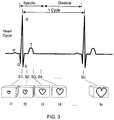
- FIG. 3is a schematic illustration of a sample of a periodic human characteristic signal associated (e.g., gated), with a set of images according to an embodiment.
- a periodic human characteristic signal associatede.g., gated
- FIG. 4is a flow chart of a method according to an embodiment.
- FIG. 4Ais a schematic illustration of a dataset according to an embodiment stored in a portion of the system of FIG. 2 .
- FIG. 5is a flow chart of a method according to an embodiment.
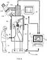
- FIG. 6is a schematic illustration of a system according to an embodiment, and a physician and a patient.
- FIG. 7is a set of images produced by the system of FIG. 6 .
- FIG. 8is a flow chart of a method according to an embodiment.
- FIG. 9is a flow chart of a method according to an embodiment.
- FIG. 10is a front view of a portion of the system of FIG. 1 .
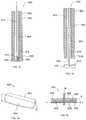
- FIG. 11is a front view of an apparatus according to an embodiment.
- FIG. 12is a top view of the apparatus of FIG. 11 .
- FIG. 13is a cross-sectional view of the apparatus of FIG. 11 taken along line X.sub. 1 -X.sub. 1 of FIG. 12 .
- FIG. 14is a front view of an apparatus according to an embodiment.
- FIG. 15is a cross-sectional view of the apparatus of FIG. 14 .
- FIG. 16is a cross-sectional view of an apparatus according to an embodiment.
- FIGS. 17 and 18are cross-sectional views of an apparatus according to an embodiment in a first configuration and a second configuration, respectively.
- FIG. 19is a perspective view of a portion of the apparatus of FIGS. 17 and 18 .
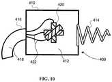
- FIG. 20is a cross-sectional view of the portion of the apparatus illustrated in FIG. 19 taken along line X.sub. 2 -X.sub. 2 , and a cross-section of a portion of a medical instrument.
- FIG. 21is a flow chart of a method according to an embodiment.
- apparatus and methods directed to enabling the use of dynamic imaging modalities in a 2-dimensional (2-D), 3-dimensional (3-D), and/or 4-dimensional (4-D) image guided intervention (IGI), and specifically to use of such modalities in sealing a bodily opening, such as those that may be formed during an invasive medical procedure,are described herein. Also disclosed herein are apparatus and methods for sealing such a bodily opening in the patient, and specifically to apparatus and methods for sealing such an opening in a dynamic bodily tissue.
- a systemis configured for use with respect to a target dynamic anatomy, or anatomy that exhibits more than minimal movement with respect to a patient's cardiac and/or respiratory cycle (e.g., with respect to the patient's heartbeat and/or breathing).
- target anatomyinclude the heart, lungs, kidneys, liver, and/or blood vessels.
- the systemcan be configured to synchronize positional information associated with a location of at least one reference marker disposed proximate to the body of the patient with at least one image that represents the target anatomy of the patient when the target anatomy is in a particular orientation and/or configuration.
- the systemis configured to select an image that represents the target anatomy at a specified time (e.g., a time at which expiration of air from the lungs is occurring).
- the systemis configured to superimpose a representation of a medical instrument on the image after making a transformation of the instrument from a tracking space (e.g., an area proximate to the patient's body, or a real coordinate space) to an image space (e.g., a computer-assisted representation of the image of the target anatomy).
- a methodincludes selecting an image from a set of images depicting a target dynamic anatomy such that the selected image is associated with a current position and/or orientation of the target dynamic anatomy in an operating theatre (e.g., a medical facility, a doctor's office, or an operating room).
- the methodcan include synchronizing a location of a reference marker that is proximate to the body of the patient (in the form of a vector, for example) to each image in the set of images.
- the methodcan also include calculating a transformation between a tracking space and an image space using the positional information of the marker in order to superimpose a live (or current) position of a medical instrument onto a display of the image.
- a method of delivering a sealant using a dynamic imaging modalityincludes viewing a representation of an instrument disposed within a body of a patient.
- the representation of the instrumentis superimposed on an image from a set of images associated with a cyclical movement of a body part.
- the imageis associated with a match dataset vector (MDV).
- MDVis a dataset vector associated with a current vector that is calculated based on a current position of a first reference marker and a current position of a second reference marker.
- the second reference markeris depicted in at least one image from the set of images.
- the methodincludes adjusting a position of the instrument based on the viewing such that a portion of the instrument is at a location within the body of the patient.
- the locationcan be, for example, adjacent a surface of a body part (e.g., the heart, the lung, etc.)
- the methodincludes delivering a sealant via the instrument to the location within the body of the patient.
- the sealantis configured to seal an opening in the body part.
- an apparatusin some embodiments, for example, includes a first shaft and a second shaft.
- the first shaftdefines a lumen and an opening in communication with the lumen of the first shaft. At least a portion of the first shaft is disposable within a body of a patient.
- the second shaftdefines a chamber and an opening in communication with the chamber of the second shaft. The chamber of the second shaft is configured to receive a sealant.
- the second shaftis configured to be movably received within the lumen of the first shaft.
- the second shafthas a first position in which the opening of the second shaft is fluidically isolated from the opening of the first shaft and a second position in which the opening of the second shaft is in fluid communication with the opening of the first shaft.
- the opening of the first shaft and the opening of the second shaftdefine a flow passageway for the sealant when the second shaft is in its second position.
- an apparatusin some embodiments, includes an elongate shaft and a delivery mechanism.
- the elongate shafthas a proximal end portion and a distal end portion.
- the elongate shaftdefines a lumen. At least a portion of the elongate shaft is disposable within a body of a patient.
- the delivery mechanismis movably coupled to the elongate shaft.
- the delivery mechanismis configured to move a seal member configured to seal an opening within the body of the patient between a collapsed configuration and an expanded configuration. At least a portion of the seal member is disposed within the lumen of the elongate shaft when the seal member is in the collapsed configuration.
- the seal memberis configured to be disposed in the body of the patient apart from the elongate shaft and the delivery mechanism.
- an apparatusin some embodiments, includes an elongate member that defines a lumen. At least a portion of the elongate member is configured to define an opening within a bodily tissue. A coating is disposed on at least a portion of an outer surface of the elongate member. The coating is configured to form a seal between the elongate member and the bodily tissue when the portion of the elongate member is within the opening of the bodily tissue.
- an apparatusin some embodiments, includes a substrate and a sealant.
- the substratehas a first surface and a second surface different than the first surface.
- the substrateis couplable to a dynamic bodily tissue within a bodily cavity of a patient.
- the substrateis penetrable by a medical instrument.
- the sealantis disposed on a portion of the substrate.
- the sealantis penetrable by the medical instrument.
- the sealantis configured to substantially prevent passage of a material through an opening in the substrate formed by the medical instrument.
- FIG. 1is an illustration of a system 100 according to an embodiment.
- the system 100can be configured to perform segmentation, correlation and registration between data obtained in “image space” (position data taken pre-procedurally) and data obtained in “tracking space” (position data obtained during a later medical procedure), as described herein and as described in detail in U.S. Patent Publication No. 2007/0060799, filed Apr. 25, 2006, entitled, “Apparatus and Method for Automatic Image Guided Accuracy Verification,” (the “'799 application”) the entire contents of which is hereby incorporated by reference.
- the system 100includes an imaging device 40 , a processor 30 , reference markers 18 , 22 , 24 , a tracker 20 , a converter 26 , and a monitor 32 .
- the system 100is configured to facilitate the performance of an IGI by a physician 14 on a patient 10 .
- the IGI system 100can be utilized for a variety of medical purposes, including, but not limited to, pacemaker lead placement, coronary stent placement, cardiac radiofrequency ablation, lung biopsy, renal stent placement, transjugular intrahepatic porto-systemic shunting, and/or percutaneous radio frequency ablation of renal masses, among other procedures.
- the IGI system 100can be used to deliver a seal member (e.g., a patch) and/or a sealant to a body part during such procedures.
- a seal membere.g., a patch
- the imaging device 40(also referred to herein as the imaging modality or scanner) is coupled to the processor 30 .
- the imaging device 40is electronically coupled to the processor 30 via a network 50 (e.g., a hospital network).
- the network 50may be any form of interconnecting network including an intranet, such as a local or wide area network, or an extranet, such as the World Wide Web or the Internet.
- the networkcan be physically implemented on a wireless or wired network, on leased or dedicated lines, including a virtual private network (VPN).
- VPNvirtual private network
- the imaging device 40is configured to take, acquire, capture, and/or generate an image of at least a portion of the body of the patient 10 , such as a portion including a target anatomy.
- the target anatomycan be an internal dynamic anatomy, such as the heart, lung, blood vessel, or the like.
- the imaging device 40is configured to take a series of images of the target anatomy.
- the imaging device 40is configured to take a set of images of the same portion of the target anatomy where each image from the set of images is taken at a different time.
- the imaging device 40is configured to take a first image of the target anatomy from a first perspective at a first time, and a second image of the target anatomy from the first perspective at a second later time.
- the imaging device 40is configured to concurrently take a set of images of the target anatomy with each image being taken from a perspective different than the perspective of the other images being taken. In this manner, the series of images can be used to generate a multi-dimensional representation of the target anatomy.
- the imaging device 40can be configured to take, acquire, capture, and/or generate the images pre-operatively, post-operatively, and/or during the operation. In some procedures, the images are taken pre-operatively to facilitate the performance of the procedure using IGI.
- the imaging device 40can be configured to take an image of the body of the patient along more than one plane.
- the imaging device 40can be any suitable 2-D, 3-D, or 4-D imaging modality.
- the imaging device 40can be configured as a single-head C-arm fluoroscope (not shown) configured to take a virtual bi-plane image by rotating the C-arm about at least two planes, which could be orthogonal planes to generate two-dimensional images that can be converted to three-dimensional volumetric images.
- the imagescan be displayed as 2-D, 3-D, and/or 4-D representations by the system 100 , such as, for example, on a graphical user interface (GUI) 31 of the processor 30 or other portion of the system 100 .
- GUIgraphical user interface
- an icon representing the location of a medical instrument 16 within the body of the patient 10can be superimposed on at least one multi-dimensional image when the image is displayed to the physician 14 .
- a 4-D surface rendering of the target anatomycan be achieved by incorporating patient data or other data from an atlas or anatomical model map, or from pre-operative image data captured by the imaging device 40 .
- the imaging device 40can be an imaging device configured for any suitable imaging modality, such as isocentric fluoroscopy, bi-plane fluoroscopy, cinematography (CINE) fluoroscopy ultrasound, high frequency ultrasound (HIFU), intra-vascular ultrasound (IVUS), computed tomography (CT), optical coherence tomography (OCT), multi-slice computed tomography (MSCT), magnetic resonance imaging (MRI), single photon emission computer tomography (SPECT), and/or positron emission tomography (PET), or any combination thereof.
- CINEisocentric fluoroscopy ultrasound
- HIFUhigh frequency ultrasound
- IVUSintra-vascular ultrasound
- CTcomputed tomography
- OCToptical coherence tomography
- MSCTmulti-slice computed tomography
- MRImagnetic resonance imaging
- SPECTsingle photon emission computer tomography
- PETpositron emission tomography
- MRIis generally performed pre-operatively using a non-ionizing field.
- MRIcan provide a desired quality of tissue visualization in 3-D form and can provide anatomical and functional information from the imaging.
- MRI datacan be registered and compensated for motion correction using a reference marker, as described in more detail herein.
- PETis generally a pre-operative imaging procedure that can expose the patient to some level of radiation to provide a 3-D image.
- PET datacan provide functional information and also can be registered and compensated for motion correction using a reference marker.
- CTis also generally a pre-operative technique that exposes the patient to a limited level of radiation.
- CTcan be a very fast imaging procedure, at least as compared to imaging procedures using a different type of imaging device.
- a multi-slice CT systemcan provide a set of 3-D images having a desired quality of resolution and anatomical information.
- CT imaging datagenerally can be registered and compensated for motion correction using a reference marker.
- Fluoroscopyis generally an intra-operative imaging procedure that can expose the patient to a certain amount of radiation and that can provide 2-D and/or rotational 3-D images. Fluoroscopic images generally provide a desired quality of resolution and anatomical information. Fluoroscopic images can be either manually or automatically registered and can also be compensated for motion correction using a reference marker. Ultrasound imaging is also generally an intra-operative procedure which uses a non-ionizing field to provide either 2-D, 3-D, or 4-D imaging, including anatomical and/or blood flow information. Ultrasound imaging provides automatic registration and does not need to account for any motion correction. Such imaging modalities are also described in U.S. Patent Publication No. 2006/0025677, filed Jul. 11, 2005, entitled, “Method and Apparatus for Surgical Navigation,” the entire contents of which is hereby incorporated by reference.
- the imaging device 40includes a hybrid imaging modality.
- the imaging device 40can be a hybrid of PET and CT.
- the imaging device 40can be a hybrid of SPECT and CT.
- the hybrid imaging modalitycan provide functional image data superimposed onto anatomical data to be used to navigate to and/or localize target anatomy within the patient 10 , as described in more detail herein.
- the imaging device 40can be a gated imaging device, such as, for example, an electrocardiogram-gated (ECG-gated) magnetic resonance imaging (MRI) device and/or an ECG-gated computed tomography (CT) device.
- ECG-gatedelectrocardiogram-gated
- MRImagnetic resonance imaging
- CTcomputed tomography
- the monitor 32e.g., an ECG monitor
- the monitor 32 and the imaging device 40are each in electrical communication with the processor 30 . In this manner, the imaging device 40 is gated based on information received by the processor from the monitor 32 , as described in detail herein.
- the imaging device 40can be configured to acquire the image(s) on a time-gated basis triggered by a physiological (or physiologically-related) signal.
- the physiological signalcan be an ECG signal acquired via the leads 34 (or from a sensing electrode included on the medical instrument 16 or from a separate reference probe).
- a characteristic of this signalsuch as an R-wave peak or P-wave peak associated with ventricular or atrial depolarization, respectively, may be used to trigger the gate image acquisition with the imaging device 40 .
- the imaging device 40is configured to take a set of images (e.g., images I 1 , I 2 , I 3 . . . In) of the target anatomy at distinct moments in time during the anatomy's periodic movement.
- a set of imagese.g., images I 1 , I 2 , I 3 . . . In
- each image of the set of imagesis taken in rapid succession.
- each image of the set of imagescan be taken at intervals over a specified time period.
- the set of imagescan include images of the target anatomy during various stages of the anatomy's periodic movement, such as images associated with a complete cycle of the anatomy's periodic movement.
- the imaging device 40is configured to transmit (or transfer) the set of images to the processor 30 .
- the processor 30is configured to received the images from the imaging device 40 .
- the processor 30stores the received images in a memory 44 of the processor 30 (see, e.g., FIG. 2 ).
- the processor 30is also configured to receive data via the converter 26 .
- the processor 30can be configured to receive data associated with a periodic human characteristic signal.
- the periodic human characteristic signalcan be, for example, a phase or a waveform of an ECG signal received from the patient 10 by the monitor 32 via the leads 34 coupled to the patient 10 and that is transmitted to the processor 30 .
- the human characteristic signalcan be a signal associated with a heart beat, as shown in FIG. 3 .
- the processor 30is configured to associate at least one image taken by the imaging device 40 with a sample of the periodic human characteristic signal to generate a gated signal sample.
- a set of gated signal samplesforms a gated dataset 42 .
- each image of the set of images(represented as images I 1 , I 2 , I 3 , I 4 . . . In) is associated with (or correlated to) a respective periodic human characteristic signal sample (represented as signal samples S 1 , S 2 , S 3 , S 4 . . . Sn, respectively).
- the image 11corresponds to the image that was taken at a moment of the patient's 10 ECG cycle that is represented by the signal sample S 1 .
- the image 12corresponds to the image that was taken at a moment of the patient's 10 ECG cycle represented by the signal sample S 2
- the image 13corresponds to the image that was taken at a moment of the patient's ECG cycle represented by the signal sample S 3
- the gated dataset 42can be used during the medical procedure for navigation and/or localization of the medical instrument 16 when the medical instrument 16 is used on the patient's body.
- the designations of P, Q, R, S, and Tare included in FIG. 3 to identify depolarizations and re-polarizations of the heart.
- the processor 30is also configured to receive data associated with at least one reference marker 18 , 22 , 24 that is transmitted to the processor 30 .
- the data from the reference markers 18 , 22 , 24can be transmitted, for example, via at least one of the tracker 20 and the converter 26 .
- the datacan include, for example, positional information associated with at least one of the reference markers (e.g., reference marker 18 , 22 , and/or 24 ).
- the processor 30includes a processor-readable medium storing code representing instructions to cause the processor 30 to perform a process.
- the processor 30can be, for example, a commercially available personal computer, or a less complex computing or processing device that is dedicated to performing one or more specific tasks.
- the processor 30can be a terminal dedicated to providing an interactive GUI 31 .
- the GUI 31can be configured to display a multi-dimensional representation of the target anatomy based on the set of images stored in the memory 44 .
- the GUIcan also be configured to display a representation (or icon) 33 of a medical instrument, such as instrument 16 , superimposed on an image of the target anatomy.
- the processor 30can be a commercially available microprocessor.
- the processor 30can be an application-specific integrated circuit (ASIC) or a combination of ASICs, which are designed to achieve one or more specific functions, or enable one or more specific devices or applications.
- the processor 30can be an analog or digital circuit, or a combination of multiple circuits.
- the processor 30includes code with instructions to generate at least a portion of the gated dataset 42 , such as generating at least one dataset vector associated with at least one image of the set of images taken by the imaging device 40 .
- the softwareincludes code with instructions to choose an image that represents a current orientation of the live target anatomy utilizing information in the dataset 42 , as described in more detail herein.
- the processor 30can include a memory 44 (schematically illustrated in FIG. 2 ).
- the memory 44can include one or more types of memory.
- the memory 44can include a read only memory (ROM) component and a random access memory (RAM) component.
- the memory 44can also include other types of memory that are suitable for storing data in a form retrievable by the processor 30 .
- EPROMelectronically programmable read only memory
- EEPROMerasable electronically programmable read only memory
- flash memoryas well as other suitable forms of memory can be included within the memory component.
- the processor 30can also include a variety of other components, such as for example, co-processors, graphic processors, etc., depending upon the desired functionality of the code.
- the processor 30can store data in the memory 44 or retrieve data previously stored in the memory 44 .
- the components of the processor 30can communicate with devices external to the processor 30 by way of an input/output (I/O) component (not shown).
- I/O componentcan include a variety of suitable communication interfaces.
- the I/O componentcan include, for example, wired connections, such as standard serial ports, parallel ports, universal serial bus (USB) ports, S-video ports, local area network (LAN) ports, small computer system interface (SCSI) ports, and so forth.
- the I/O componentcan include, for example, wireless connections, such as infrared ports, optical ports, Bluetooth® wireless ports, wireless LAN ports, or the like.
- the medical instrument 16can be any suitable device used by the physician 14 during the IGI. At least a portion of the medical instrument 16 is configured to be disposed within the body of the patient.
- the medical instrument 16can be any suitable medical device, including, but not limited to, a catheter, a needle, a stylet, a probe, a suction tube, an implant, an insert, a capsule, a sealant delivery device, a guidewire, a stent, a filter, an occluder, a retrieval device, a camera, a scope, a biopsy tool, a light source, and/or a lead.
- the medical instrument 16can also be an instrument according to an embodiment, as described in detail herein.
- the medical instrument 16is configured as a tubular member having a co-axial access path through which a biopsy needle can be inserted into the patient's body through the tubular member.
- the tubular membercan be configured as a co-axial therapy delivery system such that therapeutic agents can be delivered through the tubular member.
- the medical instrument 16can be a catheter configured to be inserted into the right atrium of the patient's heart by way of the inferior vena cava and/or a femoral artery access point.
- the tracker 20is configured to detect (or track) the positional information of at least one of the reference markers 18 , 22 , 24 .
- the tracker 20can be any suitable tracking system, including, but not limited to, an electromagnetic tracking system.
- An example of a suitable electromagnetic tracking systemis the AURORA® electromagnetic tracking system, commercially available from Northern Digital Inc. in Waterloo, Ontario, Canada.
- the tracker 20includes an electromagnetic field generator configured to emit a series of electromagnetic fields, which are designed to reach a portion of the body of the patient 10 at which at least one of the reference markers 18 , 22 , 24 is disposed.
- the electromagnetic fieldcan, for example, induce a voltage in the at least one of the reference marker 18 , 22 , 24 that can be monitored and translated into a coordinate position of the at least one of the reference marker 18 , 22 , 24 .
- the tracker 20includes a localizer (not shown), such as an optical, an acoustic, or another localizer depending upon the system for which the localizer is chosen.
- the tracker 20includes a transmitter coil array and/or a coil array controller.
- the reference marker 18also referred to herein as an instrument reference marker, is configured to be detected by the tracker 20 .
- the reference marker 18is disposed on and/or coupled to the medical instrument 16 in a known position. In this manner, a position, orientation, and/or location of the reference marker 18 (also referred to herein at the position or the positional information) as detected by the tracker 20 can be associated with a position of the medical instrument 16 with respect to the body of the patient 10 .
- the positional information associated with the location, orientation, and/or position of the reference marker 18 , and thus the medical instrument 16can be identified by the tracker 20 and transmitted to at least one of the converter 26 and the processor 30 .
- the reference marker 18can be any suitable marker configured to be detected by the tracker 20 .
- the reference marker 18is or includes a coil, or an electromagnetic coil specifically, configured to receive an induced voltage, which voltage can be detected by the tracker 20 .
- the reference marker 22also referred to herein as an external reference marker, is configured to be disposed at a location that is proximate to the target anatomy and that exhibits no or negligible movement with respect to the patient's heartbeat and/or respiration. In other words, the reference marker 22 is configured to be disposed at a static location.
- the reference marker 22can be securely fixed to a table 12 upon which the patient 10 is secured. In some procedures, for example if the patient 10 is not secured to the table 12 , the reference marker 22 can be disposed on a portion of the patient's 10 static anatomy (e.g., a region of the patient's back). A position, location, and or orientation of the reference marker 22 is configured to be tracked by the tracker 20 , as described herein.
- the reference marker 22can be any suitable reference marker, such as any of the types of reference markers described herein.
- the reference marker 24is configured to be disposed in the region of the patient's body where the IGI will be performed. Specifically, the reference marker 24 is configured to be disposed at an anatomic location within the body of the patient 10 that exhibits movement correlated to and/or associated with a movement of the target anatomy (i.e., the anatomy intended for IGI). In some embodiments, the reference marker 24 is configured to be disposed at a location internal to the body of the patient. A position, location, and/or orientation of the reference marker 24 is configured to be detected by the tracker 20 , as described herein. In some embodiments, the reference marker 24 can be any suitable reference marker, such as any of the types described herein. In some embodiments, for example, the reference marker 24 is a non-tissue internal reference marker, also referred to as a “fiducial,” that is positioned within the body of the patient 10 and that is not made from the patient's bodily tissue.
- a non-tissue internal reference markeralso referred to as a “fiducial,” that
- At least one of the medical instrument 16 , the reference markers 18 , 22 , 24 , and/or the tracker 20is couplable to the converter 26 of the system 100 .
- the converter 26is configured to receive a measurement, e.g., an analog measurement, from at least one of the reference markers 18 , 22 , 24 and/or the tracker 20 .
- the converter 26is configured to convert the analog measurement into digital data that can be received and/or processed by the processor 30 , which is couplable to the converter 26 .
- the converter 26is also configured to transmit the digital data to the processor 30 .
- the converter 26can be, for example, a break-out box.
- the converter 26includes an isolator circuit, such as an isolator circuit of the type that may be included in a transmission line or a line carrying a signal or a voltage to another portion of system 100 (e.g., the processor 30 ).
- the converter 26is configured to electronically isolate at least the portion of the medical instrument 16 that is in contact with the patient 10 should an undesirable electrical surge or voltage occur.
- the converter 26is illustrated as a distinct portion of system 100 , in some embodiments, the converter is included in the processor 30 , the medical instrument 16 , and/or another suitable portion of system 100 .
- the monitor 32is configured to be coupled to the body of the patient 10 and to the processor 30 .
- the monitor 32is configured to receive and/or monitor a periodic human characteristic signal from the patient 10 .
- the periodic human characteristic signalcan be, for example, a signal associated with at least one of heart beat and/or respiration.
- An example of a human characteristic signalis shown in FIG. 3 .
- the monitor 32can be an ECG monitor configured to receive an ECG signal in the form of an ECG data transmitted to it by an ECG lead 34 coupled to the patient 10 .
- the monitor 32is configured to transmit the periodic human characteristic signal (e.g., the ECG data) to the processor 30 .
- the reference marker 24is placed in the gross anatomical region of interest for the procedure. After placement of the reference marker 24 , a series of images of at least a portion of the body of the patient 10 is taken, produced, captured, and/or generated with the imaging device 40 .
- the gated dataset 42 generated by the imaging device 40is transferred to the processor 30 .
- the patient 10can be secured to operating table 12 and/or to portions of the system 100 , including, for example, the tracker 20 , the converter 26 , the processor 30 , the monitor 32 , and/or the imaging device 40 .
- the software of the processor 30can begin an operation sequence. In some embodiments, the software first enters a Calibration State, as described below.
- FIG. 4is a flow chart of a method 60 of performing the Calibration State. Although the activities of method 60 can be performed with any suitable system, for the sake of illustration, the activities of method 60 are described herein with reference to system 100 and FIGS. 1-3 .
- the method 60includes loading a gated dataset into a memory, 62 .
- the code and/or softwareincludes instructions to load the gated dataset 42 into the memory 44 of the processor 30 .
- the method 60optionally includes generating the gated dataset.
- the gated datasetcan be generated by the imaging device, monitor, and/or processor, as shown and described above.
- the method 60also optionally includes looping through each gated signal sample, 64 , and sampling a live periodic human characteristic signal, 66 .
- the methodincludes looping through each gated signal sample S 1 , S 2 , S 3 . . . Sn while a live periodic human characteristic signal is sampled and/or received from patient 10 via the monitor 32 .
- the signalcan be, similar to the periodic human characteristic signal used in generating the gated dataset 42 such as an ECG signal or waveform.
- a live ECG waveformcan be sampled with respect to each gated signal sample used to construct the gated dataset.
- the method 60includes comparing the live periodic human characteristic signal sample to the gated dataset, 68 .
- the methodincludes comparing the live periodic human characteristic signal (e.g., the ECG waveform) sample of the patient 10 to a gated signal sample Si (e.g., sample S 1 , S 2 , or Sn) of the gated dataset 42 . If the live periodic human characteristic signal matches the gated signal sample Si, the method continues, for example, to activity 70 . If the live periodic human characteristic signal sample does not match the gated signal sample of the gated dataset 42 , activities 64 , 66 and 68 are repeated, for example, until a matching gated signal sample is detected.
- the live periodic human characteristic signale.g., the ECG waveform
- the live periodic human characteristic signalis said to match the gated sample when the periodic human characteristic signal previously acquired is substantially equal to the live periodic human characteristic signal.
- a matchcan be ascertained using a signal processing technique that, in the case of an ECG waveform, examines historical waveform amplitudes.
- a matchcan occur, for example, when certain coordinates or other data associated with the samples to determine if the live sample and the gated sample are sufficiently equivalent for purposes of the IGI.
- the method 60includes receiving a position of an external reference marker and a position of an internal reference marker, 70 .
- the tracker 20is polled for the position information after the live periodic human characteristic signal sample is matched to the gated signal sample.
- the softwarequeries the tracker 20 for the reference marker (e.g., reference marker 22 , 24 ) positional information and the information is received by the processor 30 .
- the method 60includes generating, calculating, and/or constructing a dataset vector associated with the positional information of the external reference marker and positional information of the internal reference marker, 72 .
- positional informationis also referred to herein as the tracking space coordinates.
- the code and/or software of the processor 30can calculate a dataset vector Vi using the positional information of the external reference marker 22 and the internal reference marker 24 .
- FIG. 4Ashows a schematic illustration of a dataset including the dataset vector Vi.
- each dataset vectorcan be characterized by a magnitude and a direction generated using data associated with the positional information of the external reference marker 22 and data associated with the positional information of the internal reference marker 24 .
- the positional information of the external reference marker 22can be characterized as an origin and the positional information of the internal reference marker 24 can be characterized as an end-point for a dataset vector that begins at the origin and ends at the end-point.
- multiple internal reference markersare disposed within the body of the patient, thus multiple vectors may be generated.
- the method 60includes associating the dataset vector with an image that corresponds to (or that is associated with) the gated signal sample, 74 .
- a processore.g., processor 30
- a software programcan store the dataset vector in a look-up table with a pointer to an image Ii (e.g., Image I 1 , I 2 . . . In) that corresponds to the gated signal sample Si of gated dataset 42 .
- FIG. 4Ashows a schematic illustration of a look-up table including the image Ii.
- the dataset vectoris associated with a particular image Ii, thus the image can be referred to as a mapped image.
- the method 60includes repeating the looping 64 , the sampling 66 , the matching 68 , the receiving 70 , the generating 72 , and/or the associating 74 until each activity has been performed for each gated signal sample, and thus resulting in a set of dataset vectors stored in the look-up table.
- Each dataset vector of the set of dataset vectorsis associated with an image that corresponds to the gated signal sample.
- the periodic human characteristic signal monitor 32e.g., ECG monitor
- the methodalso includes performing a transformation calculation.
- the method 60also includes, for each dataset vector in the look-up table, examining each mapped image, 75 .
- each mapped imagecan be analyzed to identify data associated with the positional information of at least one of the external reference marker and the internal reference marker used to create the dataset vector with which the mapped image is associated.
- the image space coordinate of the internal reference marker in each imageis determined, 76 .
- the image space coordinatescan include, for example, voxel, volumetric pixel, and/or another suitable coordinate.
- the processor 30can perform a segmentation procedure to identify the actual position data associated with the reference markers 22 , 24 within the image dataset. Segmentation is the process of identifying reference points in the 3D image dataset. The purpose of the segmentation is to automatically locate potential “landmarks” in the dataset that indicate a location where a reference marker 22 , 24 may be located. Segmentation can be performed in a variety of different manners, as described in detail in the '799 application.
- the image Iiundergoes a thresh-holding segmentation during which the processor 30 determines (or finds) the image space coordinate of the internal reference marker 24 in the image Ii.
- the processor 30can perform an automated segmentation procedure.
- an automatic segmentation processcan include, intensity filtering, connectivity analysis, and size and shape filtering to identify candidate marker locations, or image space coordinates of the marker candidates.
- an automatic correlation processcan be performed.
- Correlationas used here is the process of matching and/or associating reference points between the image space and the tracking space. Matching and/or associating the reference points can aid in accurately computing the registration between the data in the image space and the data in the tracking space without user interaction.
- the correlation processdetermines where each of the reference markers 22 , 24 (or a localization element coupled to each reference marker 22 , 24 ) is positioned in the images.
- the correlation processcan be used in the computation of a transformation between image space and tracking space.
- the apparatuses and methods described hereinenable the correlation process to be automated with minimal user intervention. Automatic correlation results in an association of the location of the markers (e.g., reference markers 22 , 24 ) in image space and tracking space, as well as the corresponding labeling/identification of each marker in each space.
- the processor 30can perform an automatic registration process.
- the process of registrationtracks temporal movement of the dynamic body part via the movement of the reference markers 22 , 24 .
- the automatic registration processcan compute the transformation between the tracking space and the image space.
- the method 60also includes calculating a transformation between the tracking space and the image space using the positional information of the external reference marker and the internal reference marker, 78 .
- the positional informatione.g., the tracking space positions
- the transformation Tican be calculated, for example, using a least squares method.
- the method 60includes associating the transformation with the image in question, 80 .
- the transformation Tican be associated (or linked) to the image Ii.
- the look-up tableincludes a dataset that includes the pre-operative images, at least one of the images (and, in some embodiments, each image) depicting the internal reference marker 24 , being linked to a dataset vector and a transformation, and being at least 2D.
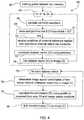
- FIG. 5is a flow chart of a method 90 of performing the Navigation State. Although the activities of method 90 can be performed with any suitable system, for the sake of illustration, the activities of method 90 are described herein with reference to system 100 and FIGS. 1-3 .
- the method 90can include an infinite loop of events, 92 .
- the methodincludes receiving a current position of an external reference marker and a current position of an internal reference marker, 94 .
- “current”does not necessarily imply that the position of the external reference marker and the position of the internal reference marker are sampled and/or received at the same time (e.g., simultaneously and/or instantaneously), rather, the term “current” is used to differentiate between the positions received at this activity from the positions received at a previously completed activity, for example.
- the processor 30can obtain the position information as described above with respect to method 60 , which can be different than the positional information received at activity 92 .
- the method 90includes constructing a current vector, 96 .
- the methodcan include constructing a current vector using the current positions of the external reference marker and the internal reference marker received at activity 94 .
- the method 90includes comparing the current vector to the dataset vectors, 98 .
- the softwarecompares the current vector to the dataset vectors (e.g., V 1 , V 2 . . . Vn) to determine the dataset vector associated with the current vector being analyzed.
- the generation of the dataset vectorsis described above with reference to method 60 and FIG. 4A .
- the method 90also includes determining whether the current vector matches the dataset vector, 101 . If the current vector does not match the dataset vector, the comparing of the current vector to the dataset vectors and the determining of the matching is repeated, e.g., until the current vector matches the dataset vector. If the current vector does match the dataset vector, the matching look-up table dataset vector (Vi) (or tracking space coordinates) is defined as the match dataset vector (MDV).
- Vilook-up table dataset vector
- MDVmatch dataset vector
- the method 90includes loading an image from the gated dataset pointed to by (or associated with) the MDV, 102 .
- the methodincludes loading into the memory 44 of the processor 30 the image from the gated dataset 42 that is associated with (or pointed to by) the MDV.
- the method 90includes loading the transformation associated with the MDV and the correlated image, 104 .
- the methodincludes loading into the memory 44 of the processor 30 the transformation Ti associated with the MDV Vi and the correlated image Ii.
- the method 90includes receiving the current position of the instrument reference marker, 106 .
- the processor 30can receive the position of instrument reference marker 18 from the tracker 20 obtain (e.g., via the converter 26 ).
- the method 90also includes applying a transformation to the position of the instrument reference marker, 108 .
- the transformationcan be a transformation procedure as described above with reference to method 60 .
- the position of the instrument reference markeris transformed into image space.
- the software of the processor 30applies the transformation Ti to the position of the instrument reference marker 18 to transform that position into image space.
- the method 90includes superimposing a representation of the instrument on the image, 110 .
- the software of the processor 30superimposes (e.g., renders, draws, or the like) a representation 33 (e.g., an iconic representation) of the medical instrument 16 on the selected image Ti displayed on the GUI 31 of processor 30 .
- the activities of method 90can be repeated.
- Repeated performance of the activities of method 90can, for example, provide the physician 14 with a live representation of the medical instrument 16 with respect to the live position and orientation of the target anatomy, thus facilitating guidance of the medical instrument 16 to a desired location within the body of the patient, e.g., to deliver medical therapy and/or perform a medical procedure.
- a system 200 according to an embodimentis illustrated in FIG. 6 .
- the system 200is configured to be used in performing and IGI using an imaging modality, such as CINE 2D fluoroscopy, that can be utilized within the operating theater during the medical procedure.
- an imaging modalitysuch as CINE 2D fluoroscopy
- the physician 14need not gate the periodic human characteristic signal to a pre-operative image, as described above with reference to system 100 .
- the system 200is similar in many respects to system 100 , except that the system 200 does not include association with the network 50 .
- the imaging deviceis illustrated in FIG. 6 as a fluoroscope 215 .
- the medical instrument 16 , the reference markers 18 , 22 , 24 , the converter 26 , the monitor 32 , and the processor 30are configured to be coupled and in communication as described above.
- the processor 30includes software instead of or in addition to the software described above.
- the processor 30includes software that comprises code providing instructions to perform a Calibration State 250 and/or a Navigation State 350 utilizing a fluoroscopy imaging modality, as described in more detail herein.
- the fluoroscope 215is coupled to the processor 30 .
- the fluoroscope 215includes a stand 210 , a receiver unit 212 (e.g., a fluoroscope radiation receiver unit), and a calibration jig 214 .
- the calibration jig 214is couplable to the receiver unit 212 .
- the fluoroscope 215is configured to take at least one image of the target anatomy of the patient 10 .
- the fluoroscope 215can be configured to take a set of images I 1 , I 2 . . . In of the target anatomy.
- the internal reference markerplaced within the body as described above, is tracked by the tracker 20 as each image of the set of images I 1 , I 2 . . . In is taken, produced, and/or generated with the fluoroscope 215 .
- the placement of the internal reference marker 24is illustrated in FIG. 7 with respect to the heart, and more specifically, with respect to various stages of the heart's function (A 1 , A 2 . . . An).
- the vector (V 1 , V 2 . . . Vn)described in more detail herein, can be determined based on the positions of each of the external reference marker (not shown) and the internal reference marker 24 , as illustrated in FIG. 7 in terms of the X, Y, and Z axis information.
- an image most accurately depicting the target anatomye.g., the heart
- an image most accurately depicting the target anatomye.g., the heart
- the patient 10can be placed upon the table 12 .
- an ECG monitor 32can be connected to the patient 10 for diagnostic purposes unrelated to performing image guidance.
- the fluoroscope 215is positioned to allow images to be taken of patient 10 .
- the physician 14can select the appropriate orientation of the patient 10 , such as a orienting the patient to obtain a Right Anterior Oblique (RAO) view.
- the physician 14can place the external reference marker 22 , as described above, at a location that exhibits no or minimal movement with respect to the patient's 10 heartbeat and/or respiration.
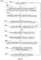
- FIG. 8is a flow chart of a method 250 (e.g., a Calibration State) according to an embodiment.
- the method 250includes receiving a live video feed from the fluoroscope, 252 .
- the physician 14can cause the fluoroscope 215 to begin acquiring an image signal (e.g., a CINE fluoroscopy loop).
- the live video feedcan be sent to, and received by, the processor 30 .
- the method 250includes sampling an image from the live video feed, 254 .
- the methodcan include sampling the live video feed.
- the samplingcan occur at a rate greater than 30 Hz so as capture a number of images (e.g., image frames) that, when pieced together, appear to be a real time image to the human eye.
- a sampling rate greater than 60 Hzcan be implemented in accordance with Nyquist's Law.
- the method 250includes storing an image in memory, 256 .
- the memorycan be similar in many respects to memory 44 , described above.
- the methodincludes producing an image Ii, such as an image frame illustrated in FIG. 7 , and storing that image into the memory 44 of the processor 30 .
- the method 250includes receiving a position of a reference marker, 258 .
- the receiving the position of the reference markercan be performed in a similar manner as described above with respect to method 60 .
- the methodcan include receiving positional information associated with at least one of the reference markers 22 , 24 from the tracker 20 .
- the method 250includes constructing a dataset vector using the positional information of the reference markers, 260 .
- the methodincludes constructing and/or calculating, a dataset vector Vi (e.g., dataset vector V 1 , V 2 . . . Vn) that defines the orientation of the reference markers 22 , 24 during the time of acquisition of the image Ii.
- a dataset vector Vie.g., dataset vector V 1 , V 2 . . . Vn
- the method 250also includes recording the dataset vector and the associated image in a dataset, 262 .
- the methodincludes recording the dataset vector Vi and the associated image Ii in a dataset 300 .
- the dataset 300can include, for example, a look-up table, as illustrated in FIG. 9 and described below.
- the dataset 300can reside in the memory 44 of the processor 30 .
- the dataset 300includes at least one image that depicts a non-tissue internal reference marker, is linked to positional information about the non-tissue internal reference marker, and is at least 2D.
- the softwarecan initiate a transformation calculation process, e.g., for each image in a set of images, 263 , after the set of images have been collected and/or stored.
- the transformationcan be implemented as described above with respect to method 60 .
- the method 250includes receiving a position of the calibration jig, 264 .
- the code and/or software of processor 30includes code comprising instructions to receive positional information associated with the position of the calibration jig 214 for each image Ii.
- the softwarepolls the tracker 20 for and receives from the tracker 20 the positional information of the calibration jig 214 .
- the method 250includes calculating a transformation using the calibration jig positional information and the database vector, 266 .
- the softwarecalculates a transformation Ti from a tracking space (e.g., the tracker field coordinate space) to image space (e.g., the fluoroscope image space) using the methods disclosed herein.
- the method 250also includes storing the transformation with the image, 268 .
- the transformation Tiis stored in association with (e.g., linked to) the image Ti in the look-up table associated with the database vector Vi. In this manner, the transformation Ti is associated with the image Ii.
- the activities of method 250can be repeated, for example, until the periodic cycle of movement of the target anatomy is captured by the images taken.
- FIG. 9is a flow chart of a method 350 according to an embodiment.
- the method 350includes performing a Navigation State, which can be initiated by the code and/or software of the processor 30 .
- a Navigation Statecan be initiated by the code and/or software of the processor 30 .
- the activities of method 350can be performed with any suitable system, for the sake of illustration, the activities of method 350 are described herein with reference to system 200 .
- the softwarecan enter an infinite loop of activities, 352 .
- the method 350includes receiving a current position of at least two reference markers, 354 .
- the position informationcan be received, for example, in a manner similar to the receiving 94 described above with respect to method 90 .
- the processor 30can receive positional information associated with the at least two reference markers from the tracker 20 via the converter 26 .
- the processorcan receive current position information, for example, that is associated with the position of each of the external reference marker 22 and the internal reference marker 24 .
- the method 350includes generating (or constructing) a current vector using the current positions, 356 .
- the generating 356can be implemented in a similar manner as the constructing 96 described above with respect to method 90 .
- the processorcan construct a current vector using the received current positions of the external reference marker 22 and the internal reference marker 24 .
- the method 350includes comparing the current vector to the dataset vectors, 358 .
- the comparing 358can be implemented in a similar manner as the comparing 98 described above with respect to method 90 .
- the methodincludes comparing the current vector to the dataset vectors (e.g., V 1 . . . Vn) to determine the dataset vector associated with the current vector being analyzed.
- the methodincludes comparing the current positions of each of the external reference marker 22 and the internal reference marker 24 to the tracking space coordinates.
- the method 350includes determining as to whether the current vector matches the dataset vector, 360 .
- the determining 360can be implemented in a similar manner as the determining 101 described above with respect to method 90 . If the current vector does not match the dataset vector, the comparing of the current vector to the dataset vectors and the determining of the matching is repeated, e.g., until the current vector matches the dataset vector. If the current vector does match the dataset vector, the matching look-up table dataset vector (Vi) (or tracking space coordinates) is defined as the match dataset vector (MDV).
- Vilook-up table dataset vector
- MDVmatch dataset vector
- the method 350also includes loading an image from the dataset that is associated with the dataset vector, 362 .
- the loading 362can be implemented in a similar manner as the loading 102 described above with respect to method 90 .
- the methodincludes loading into the memory 44 of the processor 30 the image Ii from dataset 300 associated with (or pointed to by) the MDV (Vi).
- the method 350optionally includes loading a transformation linked to the image, 364 .
- the loading 364can be implemented in a similar manner as the loading 104 described above with respect to method 90 .
- the methodincludes loading into the memory 44 of the processor 30 the transformation Ti associated with the MDV Vi and the correlated image Ii.
- the method 350includes receiving the current position of the instrument reference marker, 366 .
- the receiving 366can be implemented in a similar manner as the receiving 106 described above with respect to method 90 .
- the methodincludes receiving the position of instrument reference marker 18 from the tracker 20 .
- the method 350includes applying a transformation to the position of an instrument reference marker, 368 .
- the transformationcan be a transformation procedure as described above with reference to method 60 .
- the position of the instrument reference marker 18is transformed into image space.
- the code and/or software of the processor 30applies the transformation Ti to the position of the instrument reference marker 18 to transform the position of the instrument reference marker 18 into image space.
- the method 350includes superimposing a representation of the instrument on the image, 370 .
- the superimposing 370can be implemented in a similar manner as the superimposing 110 described above with respect to method 90 .
- the code and/or software of the processor 30superimposes (e.g., renders, draws, produced, or the like) a representation (e.g., an iconic representation) of the medical instrument 16 on the selected image Ii displayed on the GUI 31 of processor 30 .
- the activities of method 350can be repeated.
- Repeated performance of the activities of method 350can provide the physician 14 with a representation of the medical instrument 16 with respect to the live position and orientation of the target anatomy, thus facilitating guidance of the medical instrument 16 to a desired location within the body of the patient, e.g., to deliver medical therapy and/or perform a medical procedure.
- the imagescan be registered with a different registration process.
- the imagescan be registered using point registration, surface registration, pathway registration, auto-registration, or the like, or any combination thereof.
- a system and/or a methodcan include any suitable number of reference markers, e.g., two, three, or more reference markers.
- the reference marker 24can be similar in many respects to the reference marker 400 shown and described below with reference to FIG. 10 .
- the reference marker 400includes a body portion 410 , a fixation member 414 , and a channel portion 416 .
- the body portion 410defines a chamber 412 .
- the chamber 412is configured to receive at least a portion of a medical device, such as a sensor 420 .
- the body portion 410 of the reference marker 400is configured to be opaque to the imaging device 40 .
- the body portion 410is configured to be visible (e.g., as a blank or white spot) on an image of a portion of the body of the patient including the reference marker 400 taken produced, and/or generated using and imaging device (e.g., imaging device 40 ).
- the body portion 410can be constructed of a material that is opaque to the imaging device 40 .
- the body portion 410is constructed of platinum, titanium, or the like, or the like, or any suitable combination thereof.
- the fixation member 414is coupled to the body portion 410 .
- the fixation member 414is configured to facilitate retention of the reference marker 400 within the body of the patient (not shown). Similarly stated, the fixation member 414 is configured to limit movement of the body portion 410 relative to the body of the patient.
- the fixation member 414has a pig-tail shape. In this manner, the fixation member 414 is configured to be screwed into a portion of the patient's body (e.g., in bone and/or cartilage) and/or unscrewed to release the reference marker 400 from the patient's body, such as after completion of the procedure.
- the fixation member 414 of the reference marker 400is illustrated and described herein as having a pig-tail shape, in other embodiments, the fixation member can have any suitable configuration for retaining the reference marker within the body of the patient.
- the channel portion 416 of the reference marker 400is coupled to the body portion 410 .
- the channel portion 416defines a passageway 418 that is in fluid communication with the chamber 412 of the body portion 410 .
- the channel portion 416is configured to receive at least a portion of a medical device, such as sensor 420 .
- the channel portion 416can include, for example, a sheath or a portion of a sheath.
- the channel portion 416can be constructed of any suitable material, including, for example, plastic.
- the channel portion 416can be of any suitable configuration (e.g., length, circumference, etc.). In some embodiments, for example, the channel portion 416 can have a length such that the channel portion 416 is configured to extend from a location within the body of the patient to a location exterior to the body of the patient. In this manner, the sensor 420 (or other medical device) can be inserted into the passageway 418 of the channel portion 416 outside of the body of the patient and delivered to the chamber 412 of the body portion 410 of the reference marker 400 after implantation of the reference marker 400 within the body of the patient. In some embodiments, the sensor 420 can be inserted into the chamber 412 after images of the target anatomy have been taken to generate the gated dataset 42 . For the sake of clarity, as used herein, references to the reference marker 400 should be construed as references to those portions of the reference marker that are disposed within the body of the patient during a given IGI.
- the sensor 420can include at least one connecting lead 422 configured to facilitate disposing the sensor 420 in the chamber 412 .
- the sensor 420 and/or the connecting leads 422can be secured in place with respect to the chamber 412 .
- at least one of the sensor 420 and the lead 422can be constructed of a ferrous material. In other embodiments, however, because the sensor 420 and/or lead 422 can be inserted into the chamber 412 of the body portion 410 of the reference marker 400 after generation of the gated dataset 42 (and thus after imaging by the imaging device 40 ), the sensor 420 and/or lead 422 need not be constructed of a non-ferrous material.
- the chamber 412is implanted within the body of the patient, e.g., prior to imaging with the imaging device 40 .
- the chamber 412 of the reference marker 400can be empty.
- the reference marker 400can be imaged (or scanned) with the imaging device 40 , such as when the imaging device 40 is taking pre-operative images of the target anatomy.
- the sensor 420(or other medical device) is inserted through the passageway 418 until at least a portion of the sensor 420 is disposed within the chamber 412 of the body portion 410 of the reference marker 400 .
- Each of the body portion 410 and the fixation member 414can be constructed of any suitable material configured to be disposed within a body of a patient and/or configured to be used with an imaging device (e.g., a gated scanner 40 ).
- an imaging devicee.g., a gated scanner 40
- at least one of the body portion 410 and the fixation member 414is constructed of a non-ferrous material.
- the reference marker 400is configured to comply with safety requirements of certain imaging modalities, such as an MRI device.
- the body portion 410 of the reference marker 400can be constructed of a material suitable for imaging with the imaging device 40
- the sensor 420can be constructed of a material suitable for being detected by the tracker 20 (and which may or may not be suitable for imaging with the imaging device).
- portions of the systemsare illustrated and described herein as being distinct from other portions of the system (e.g., system 100 , 200 ), in some embodiments, a portion of the system may be incorporated into another portion of the system.
- portions of the systeme.g., the tracker 20 and/or the processor 30 of systems 100 , 200
- the imaging device 40can be incorporated into the imaging device 40 . In this manner, an integrated imaging and tracking system can be provided.
- the systemcan include an imaging device having a different gated configuration.
- the systemcan be gated with a different periodic human characteristic signal.
- the gate triggering event(or the period human characteristic signal) can be a physiologically-related signal associated with the patient's 10 respiration or hemodynamics.
- a sensor regarding respirationmay be used to trigger the acquisition of the images at the same point in the respiration cycle.
- a sensorcan be coupled to the system 100 , such as an external capnographic sensor that monitors exhaled CO.sub.2 concentration and/or an airway pressure sensor, that is configured to determine the end expiration point.
- respirationboth ventriculated and spontaneous, can cause an undesirable elevation or reduction, respectively, in a baseline pressure signal, which can be used to trigger acquisition of the image(s).
- a baseline pressure signalwhich can be used to trigger acquisition of the image(s).
- any suitable imaging modality configured to be gated to a periodic human characteristic signalmay be used in performance of the methods described herein, including, but not limited to CT, MRI, CINE fluoroscopy, positron emission tomography (PET), ultrasound, and functional MRI (fMRI).
- method 60has been illustrated and described as generating the dataset vector associated with the position and/or location of the external reference marker and/or the position and/or location of the internal reference marker, 72
- the generated dataset vectorsinclude only the positional coordinates of the external reference marker and the internal reference marker, thus the generating the dataset vector need not be performed and the associating of the dataset vectors to the various images of gated dataset includes associating the positional (or tracking space) coordinates of the relevant reference markers to those images.
- method 90has been illustrated and described as comparing the current vector to the dataset vectors, 98 , in some embodiments, the current positions of the external reference marker and the internal reference marker are compared to the tracking space coordinates.
- the systems (e.g., system 100 , system 200 ) and methods (e.g., methods 60 , 90 , 250 , 350 ) described hereincan be used in performing a variety of medical procedures using IGI.
- a systeme.g., system 100 , system 200
- a methode.g., methods 60 , 90 , 250 , 350
- the medical instrument 16is used in conjunction with a navigation system (e.g., system 100 , 200 ) according to an embodiment to deliver the sealant to the body of the patient.
- a medical instrument 500 configured to deliver a sealant to a body of a patientis illustrated in FIG. 11 .
- the instrument 500can be configured to deliver at least one surgical sealant, including, but not limited to a fibrin sealant, thrombin, fibrinogen, a cyanocrylate, collagen (or a collagen-based compound), a cross-linker, an aldehyde, and/or a hydrogel, or the like, or any combination thereof.
- a suitable sealant for a particular procedurecan be selected, for example, based on certain properties of the sealant.
- Such propertiescan include, for example, the strength of the sealant; whether the sealant is biodegradable; the degree, if any, to which the sealant facilitates natural healing of a bodily wound; the sealant's barrier against infection; and/or the ease of use of the sealant.
- the instrument 500can deliver a fibrin sealant, which can include thrombin and fibrinogen, may have suitable properties for the procedure to be performed, such as, for example, properties related to tissue adhesion and/or hemostasis.
- the materials included in the fibrin sealantcan be of any suitable origin, e.g., human plasma, bovine, or another suitable source.
- the fibrin sealantalso can be configured to promote healing of a bodily wound.
- fibrin sealantcan be delivered to a puncture site formed within the lung to seal the lung.
- the fibrin sealantcan be delivered to the body of the patient as a liquid.
- the fibrin sealantcan be delivered to the body of the patient as a slurry, suspension, paste or the like.
- the instrument 500can deliver a sealant including a cyanoacrylate, which can be configured to form a seal within the body of the patient for a period of about seven to ten days.
- the cyanocrylate sealantcan be substantially water-proof and/or water-resistant, have a high strength (e.g., a strength greater than the fibrin sealant), and/or be non-bioresorbable.
- the cyanocrylate sealantis configured to stop bleeding at the portion of the patient's body on which the sealant is disposed.
- the sealantcan include a coagulant.
- the cyanocrylate sealantcan be delivered to the body of the patient via a substrate.
- the instrument 500can deliver a sealant including a collagen and/or a collagen-based compound.
- the collagen-based sealantis configured to deliver fibrinogen to the body of the patient.
- the sealantcan include any suitable known collagen-based compound, including, but not limited to FloSeal, commercially available from Sulzer Spine Tech, Proceed, commercially available from Fusion Medical Technologies, and Costasis, commercially available from Cohesion Technologies.
- the instrument 500can deliver a sealant including an aldehyde, such as gluteraldehyde.
- the aldehyde sealantis configured to fill an opening within the patient's body, such as a puncture site.
- the aldehyde sealantis configured to be delivered to the body of the patient as a liquid.
- the aldehyde sealantis configured to be disposed on an outer surface of a medical instrument, such as in a coating on an outer surface of a biopsy needle.
- the sealantcan include any suitable known aldehyde, including, but not limited to a glutaraldehyde glue, such as, for example, the glutaraldehyde glue marketed under the name BioGlue®.
- the instrument 500can deliver a sealant including any suitable hydrogel.
- the hydrogelis constructed of and/or includes a polyethylene glycol polymer, which has sealant properties that are configured to be activated upon exposure to a light source.
- the sealant including the hydrogelcan be configured to be bioabsorbable.
- the sealant including the hydrogelis configured to be delivered to the body of the patient as a liquid.
- the sealantcan be or include the hydrogel marketed under the name Focal Seal-L, commercially available from Gynzyme Bioscience.
- the instrument 500includes a first shaft 502 , a second shaft 512 , a reference marker 524 , and a sensor 526 .
- the first shaft 502defines a lumen 504 and an opening 506 in communication with the lumen 504 of the first shaft 502 . At least a portion of the first shaft 502 is disposable within the body of the patient.
- the second shaft 512defines a lumen 516 , a chamber 514 , and an opening 518 in communication with the chamber 514 of the second shaft 512 .
- the chamber 514 of the second shaft 512is configured to receive the sealant (not shown).
- the sealantcan be disposed within the chamber 514 prior to disposing the first shaft 502 within the body of the patient.
- the sealantcan be conveyed into the chamber 514 via the opening 518 before the first shaft 502 and/or the second shaft 512 are disposed within the body.
- the sealantis disposed in the chamber 514 while the first shaft 502 and/or the second shaft 512 are disposed within the body of the patient, e.g., via an injection source.
- the lumen 516 of the second shaft 512is fluidically isolated from the chamber 514 of the second shaft 512 .
- the lumen 516 of the second shaft 512is configured to receive a medical instrument.
- the lumen 516 of the second shaft 512can receive at least one of a light source, a scope, a biopsy tool, a camera, or the like.
- the second shaft 512provides access for the medical instrument to the body of the patient.
- a light sourcecan be received in and/or passed through the lumen 516 of the second shaft such that the light source is proximate to the sealant delivered to the body of the patient.
- the second shaft 512is configured to be received within the lumen 504 of the first shaft 502 .
- the second shaft 512is tightly engaged with the first shaft 502 .
- the second shaft 512is not freely movable with respect to the first shaft 502 in the absence of a force (e.g., a force applied by the physician to move the second shaft 512 ).
- the second shaft 512has a first position, as shown in FIG. 13 , in which the opening 518 of the second shaft 512 is fluidically isolated from the opening 506 of the first shaft 502 .
- the second shaft 512has a second position (not shown in FIGS.
- the opening 518 of the second shaft 512is in fluid communication with the opening 506 of the first shaft 502 .
- the opening 506 of the first shaft 502 and the opening 518 of the second shaft 512define a flow passageway for the sealant.
- the flow passagewayis configured to permit movement of the sealant from the chamber 514 of the second shaft 512 to a location exterior to the first shaft 502 .
- the second shaft 512is movable with respect to the first shaft 502 in at least one rotational direction, as indicated by arrow A.sub. 1 in FIG. 13 .
- the second shaft 512can be configured to rotate in at least one of a clockwise or a counter-clockwise direction.
- the second shaft 512is moved from its first position to its second position by rotating the second shaft 512 with respect to the first shaft 502 .
- the second shaft 512is moved to its second position to deliver the sealant to the body of the patient.
- the second shaft 512is movable with respect to the first shaft 502 in at least one longitudinal direction.
- the reference marker 524is disposed on at least one of the first shaft 502 or the second shaft 512 . In the embodiment illustrated in FIG. 11 , the reference marker 524 is disposed on an outer surface of the first shaft 502 .
- the reference marker 524is configured to be viewed by an imaging device (not shown) that is exterior to the body of the patient when the reference marker 524 is disposed within the body of the patient.
- the reference marker 524can be configured to be viewed by any imaging device (or modality) described herein, such as imaging device 40 .
- the reference marker 524is similar in many respects to the instrument reference marker 18 , described herein.
- the sensor 526is coupled to a distal end portion 503 of the first shaft 502 .
- the sensor 526is configured to sense a pressure within a portion of the body of the patient at which the sensor 526 is disposed.
- the sensor 526can be any suitable known pressure sensor, such as, for example a piezo-electric pressure transducer.
- the sensor 526is configured to sense a first pressure at a first portion of the body of the patient and a second pressure at a second portion of the body of the patient.
- the sensor 526can be characterized as being configured to detect a spatial change in pressure within the body of the patient.
- the senor 526is configured to sense a first pressure at a first time at an area within the body of the patient at which the sensor is disposed and a second pressure at a second time different than the first time at the area within the body of the patient.
- the sensor 526can be characterized as being configured to detect a temporal change in pressure within the body of the patient.
- the senor 526can facilitate delivery of the sealant because the sensor 526 can provide an indication of a desired status of a target anatomy (e.g., exhalation of the lungs) and/or an indication of a desired location of the instrument with respect to the target anatomy (e.g., when the sensor of the instrument detects the second pressure indicating the sensor of the instrument has moved from a position inside the lung to a position proximate to the surface of the lung).
- a target anatomye.g., exhalation of the lungs
- an indication of a desired location of the instrument with respect to the target anatomye.g., when the sensor of the instrument detects the second pressure indicating the sensor of the instrument has moved from a position inside the lung to a position proximate to the surface of the lung.
- a third shaftis disposed within at least one of the first shaft or the second shaft. In this manner, the second shaft need not include the lumen as described herein.
- the third shaftcan be movable with respect to at least one of the first shaft and the second shaft.
- a medical instrument 550configured to deliver a sealant to a body of a patient according to an embodiment is illustrated in FIGS. 14-15 .
- the instrument 550includes a first shaft 552 , a second shaft 560 , and a plunger 566 .
- the first shaft 552defines a lumen 554 and an opening 556 in communication with the lumen 554 of the first shaft 552 .
- the first shaft 552defines a tapered distal tip 553 .
- the tapered distal tip 553is configured to pierce, puncture and/or displace bodily tissue. In this manner, the instrument 550 is configured to penetrate a bodily tissue (e.g., the skin, the lung).
- the tapered distal tip 553is shown as being sharp, in other embodiments, the tapered distal tip 553 can include a slightly rounded tip.
- the second shaft 560defines a chamber 562 and an opening 564 in communication with the chamber 562 .
- the chamber 562is configured to receive a sealant.
- the sealantcan be any suitable sealant described herein.
- At least a portion of the second shaft 560is received within the lumen 554 of the first shaft 552 .
- the second shaft 560is movable with respect to the first shaft 552 in at least one rotational direction, as indicated by arrow A.sub. 2 in FIG. 15 , and as described above with respect to instrument 500 .
- the second shaft 560is configured to be rotated with respect to the first shaft 552 to align the opening 564 of the second shaft 560 with the opening 556 of the first shaft 552 . In this manner, the aligned openings 556 , 564 form a flow passageway through which the sealant can move from the chamber 562 to an area external to the first shaft 552 .
- At least a portion of the plunger 566is disposed within the chamber 562 of the second shaft 560 .
- the plunger 566is configured to be translationally moved with respect to the second shaft 560 .
- the plunger 566can be moved in a distal direction, for example, such that a portion of the plunger 566 contacts the sealant received in the chamber 562 . In this manner, the plunger 566 is configured to facilitate delivery of the sealant to the body of the patient.
- a medical device 580includes a second shaft 590 that is movable with respect to the first shaft 582 in at least a one translational direction, as indicated by arrow A.sub. 3 .
- the second shaft 590is configured to be translationally moved with respect to the first shaft in at least one of a proximal direction or a distal direction.
- the second shaft 590is moved from a first position in which an opening 594 defined by the second shaft 590 is fluidically isolated from an opening 586 defined by the first shaft 582 to a second position in which the opening 594 of the second shaft 590 is in fluid communication with the opening 586 of the first shaft 582 by translating the second shaft 590 with respect to the first shaft 582 .
- the second shaft 590can be moved from its first position to its second position by translationally moving a handle portion 596 coupled to the second shaft 590 (e.g., in at least one of the distal or the proximal directions).
- the first shaft 582is configured to define an opening within the bodily tissue of the patient.
- the first shaft 582includes a coating 588 disposed on at least a portion of the outer surface of the first shaft 582 .
- the coating 588is configured to form a seal between the portion of the first shaft 582 and a portion of the body B of the patient in contact with the outer surface of the portion of the first shaft 582 when the first shaft 582 defines and/or is disposed within the opening of the bodily tissue.
- the sealis formed in response to the coating 588 being exposed to a bodily fluid.
- the coating 588includes the sealant.
- the coating 588can include at least one of thrombin, fibrinogen, a cyanocrylate, collage, a cross-linker, an aldehyde, or a hydrogel, or the like, or any combination of the foregoing.
- At least one of the coating 588 or the sealanthas a first physical state prior to the coating 588 being exposed to the bodily fluid (or contacting the body B) and a second physical state different than the first physical state after the coating is exposed to the bodily fluid.
- the coating 588can include a solid material disposed on an outer surface of a portion of the first shaft 582 (e.g., a biopsy needle) and can include the sealant in the form of a liquid and/or gel within a matrix of the solid coating 588 .
- the coating 588can be configured to change from the first solid physical state to a second physical state, e.g., a liquid, in response to being exposed to the bodily fluid.
- the coating 588As the coating 588 is liquefied, the sealant is released from the matrix, and thus delivered to the body part B (e.g., skin, a lung, a heart).
- the coating 588 and the sealantare solidified on the outer surface of the medical instrument 580 (e.g., a catheter).
- the sealantAs the sealant is exposed to the bodily fluid (e.g., blood, mucous, or the like) the sealant is changed from its first physical state, e.g., solid, to its second physical state, e.g., liquid, and the seal is formed between the first shaft 582 and a portion of the body B of the patient in contact with the outer surface of the portion of the first shaft 582 .
- the coating 588is shown as being disposed about substantially all of the first shaft 582 , in other embodiments, the coating 588 can be disposed about only a portion of the first shaft 582 .
- the coating and/or the sealantcan be configured to change physical states in response to a different agent.
- at least one of the coating or the sealantis configured to change from the first physical state to the second physical state upon placing the coating and/or the sealant in contact with the body B, and/or upon placing the coating and/or sealant in contact with a second coating that is disposed on another medical instrument or on the body of the patient.
- the change in physical stateis caused by a chemical reaction between a material included in at least one of the coating 588 and the sealant and a bodily or other fluid (e.g., saline) or another material.
- the change in physical state of the coating 588can be caused by a thermal reaction (e.g., heating of the outer surface of the first shaft 582 ).
- the first shaft 582can include a heater configured to allow a user to selectively increase the temperature of the outer surface of the first shaft 582 to trigger the change in the physical state of the coating 588 .
- a delivery instrumentcan include non-coaxial shafts and/or any suitable number of shafts.
- a delivery instrumentincludes a first shaft defining a lumen and a second shaft and third shaft, each disposable within the lumen of the first shaft.
- the second shaftcan define a chamber that contains a sealant, and the third shaft can be configured to receive a medical instrument (e.g., a scope).
- a delivery instrumentcan include a first shaft having a longitudinal axis and a second shaft configured to be at least partially disposed within a lumen of the first shaft.
- the second shaftcan have a longitudinal axis that is non-coaxial with and/or nonparallel to the longitudinal axis of the first shaft.
- the longitudinal axis of the second shaftcan be parallel to the longitudinal axis of the first shaft.
- the longitudinal axis of the second shaftcan be transverse to the longitudinal axis of the first shaft.
- a delivery instrumentincludes a first shaft and a second shaft disposed adjacent the first shaft. Each of the first shaft and the second shaft defines a lumen. The lumen of the first shaft and the lumen of the second shaft are each configured to be in fluid communication with a lumen of a third shaft.
- a first sealant materialcan be disposed in the lumen of the first shaft and a second sealant material can be disposed in the lumen of the second shaft.
- At the time of delivery of the sealant to the target anatomyat least a portion of the first sealant material is moved to the lumen of the third shaft and at least a portion of the second sealant material is moved to the lumen of the third shaft. In this manner, the first sealant material and the second sealant material can be combined prior to delivery of the sealant to the target anatomy.
- the second shaft 512 of instrument 500is illustrated and described as defining the lumen 516 , in other embodiments, the second shaft can define any suitable number of lumens, e.g., two, three, or more. In other embodiments, the second shaft 512 of the instrument 500 can be devoid of a lumen.
- the lumen 516 of the second shaft 512 of instrument 500is illustrated and described herein as being fluidically isolated from the chamber 514 of the second shaft 512 , in some embodiments, the lumen of the second shaft is configured to be placed in fluid communication with the chamber of the second shaft.
- the instrument 500is illustrated and described herein as including the reference marker 524 on at least one of its first shaft 502 or its second shaft 512 , in other embodiments, the instrument includes any suitable number of reference markers on its first shaft and/or its second shaft, e.g., two, three, or more reference markers. In other embodiments, the instrument 500 need not include any reference markers.
- FIGS. 17-18A medical instrument 600 configured to deliver a seal member 620 to a body of a patient according to an embodiment is illustrated in FIGS. 17-18 .
- the instrument 600includes an elongate shaft 602 , a delivery mechanism 612 , a reference marker 616 , a sensor 618 , and a seal member 620 .
- the elongate shaft 602has a proximal end portion 603 and a distal end portion 605 and defines a lumen 606 . At least a portion of the elongate shaft is disposable within the body of the patient.
- the delivery mechanism 612is movable with respect to the elongate shaft 602 and includes a protrusion 614 . Additionally, the protrusion 614 is movable with respect to the remainder of the delivery mechanism 612 . In some embodiments, the delivery mechanism 612 is movably coupled to the elongate shaft 602 . In some embodiments, the delivery mechanism 612 is a stylet, an expandable wire mechanism, or the like. The delivery mechanism 612 is movable between a first configuration (illustrated in FIG. 17 ) and a second configuration (illustrated in FIG. 18 ). The protrusion 614 is extended from the delivery mechanism 612 at a first angle when the delivery mechanism 612 is in its first configuration.
- the first anglecan be an angle between zero and 89 degrees (i.e., an acute angle) with respect to the remainder of the delivery mechanism 612 .
- the first anglecan be an angle 90 degrees or greater with respect to the delivery mechanism.
- the protrusion 614is extended from the delivery mechanism 612 at a second angle greater than the first angle when the delivery mechanism 612 is in its second configuration.
- the protrusion 614 of the delivery mechanism 612is biased towards being extended from the delivery mechanism 612 at the second angle.
- the protrusion 614is biased in the second configuration.
- the delivery mechanism 612is configured to move the seal member 620 between a collapsed configuration (illustrated in FIG. 17 ) and an expanded configuration (illustrated in FIG. 18 ) when the delivery mechanism 612 is moved from its first configuration to its second configuration.
- the movement of the protrusion 614 from its first position to its second position, and thus movement of the seal member 620 from its collapsed configuration to its expanded configurationis similar to the operation of an umbrella.
- the seal memberis configured to seal an opening within the body of the patient when the seal member 620 is in its expanded configuration. At least a portion of the seal member 620 is disposed within the lumen 606 of the elongate shaft 602 when the seal member is in its collapsed configuration, as illustrated in FIG. 17 . In other words, at least a portion of the seal member 620 is deformable for delivery of the seal member 620 to the bodily tissue.
- the seal member 620includes a substrate 622 and a sealant 630 disposed on a portion of the substrate 622 .
- the substrate 622couplable to a bodily tissue of the patient.
- the substrate 622is couplable to a dynamic bodily tissue (e.g., the lung, the heart) within a bodily cavity of a patient.
- the substrate 622is configured to be disposed on an interior surface of an organ of the patient.
- the substrate 622can be disposed on an interior surface of the lung of the patient.
- the substrate 622has a first surface 624 and a second surface 626 different than the first surface 624 .
- An adhesive 628is disposed on the second surface 626 of the substrate 622 .
- the adhesive 628is configured to couple the substrate adjacent to the bodily tissue (e.g., the dynamic bodily tissue). At least a portion of the substrate 622 is configured to be penetrated by a medical instrument M (see e.g., FIG. 20 ). Said another way, the substrate 622 is configured to maintain its structural integrity and/or retain its functional qualities (e.g., being coupled to the bodily tissue B) when the medical instrument M is inserted through the substrate 622 .
- the sealant 630is disposed in a cavity 623 defined by the substrate 622 between the first surface 624 of the substrate 622 and the second surface 626 of the substrate.
- the sealant 630is a liquid or a gel sealant disposed in the cavity 623 of the substrate 622 .
- the sealant 630can be any suitable known sealant of the types shown and described herein.
- the sealant 630is configured to be penetrated by the medical instrument M when the medical instrument M is inserted through the substrate 622 .
- the sealant 630is configured to substantially prevent passage of a material through an opening in the substrate 622 formed by the medical instrument M.
- the sealant 630forms a seal about the portion of the medical instrument M inserted through the sealant 630 , e.g., between the medical instrument M and the substrate 622 .
- the seal member 620is configured to substantially prevent the passage of an environmental contaminant through the opening defined by the medical instrument and into the body of the patient.
- the seal member 620is configured to substantially prevent the passage of a bodily fluid from an area inside the body of the patient through the opening defined by the medical instrument.
- the delivery mechanism 612includes the reference marker 616 .
- the reference marker 616is configured to be viewed by an imaging device (e.g., imaging device 40 , described herein) that is exterior to the body of the patient when the reference marker 616 is disposed within the body of the patient.
- the reference marker 616can be, for example, any suitable reference marker described herein.
- the sensor 618is coupled to the elongate shaft 602 . At least a portion of the sensor 618 is disposed on the distal end portion 605 of the elongate shaft 602 .
- the sensor 618is configured to detect a pressure at a location within the body of the patient proximate to the distal end portion 605 of the elongate shaft 602 (and/or a portion of the delivery mechanism 612 ).
- the sensor 618can be any suitable sensor, for example, a sensor according to an embodiment (e.g., sensor 524 ) described herein.
- the medical instrument M(or another medical instrument) can be received in the elongate shaft 602 of the instrument 600 .
- the medical instrument Mcan be received in the lumen 606 of the elongate shaft 602 alongside the delivery mechanism 612 .
- the medical instrument Mcan be received in the lumen 606 of the elongate shaft 602 prior to placement of the delivery mechanism 612 within the lumen 606 of the elongate shaft 602 and/or after removal of the delivery mechanism 612 within the lumen 606 of the elongate shaft 602 .
- the medical instrument Mcan be any suitable medical instrument described herein, including, but not limited to, a light source, a scope, a biopsy tool, a camera, or the like.
- the instrument 600can be used in conjunction with a scope to facilitate placement and/or delivery of the sealant 630 to a target anatomy.
- the sealant 630is illustrated and described as being disposed within the cavity 623 of the substrate 622 , in other embodiments, the sealant can be disposed on a different portion of the substrate. For example, in some embodiments, the sealant is disposed on at least one of the first surface or the second surface of the substrate.
- the adhesive 628is illustrated and described as being disposed on the second surface 626 of the substrate 622 , in other embodiments, the adhesive can be disposed on a different portion of the substrate.
- the adhesiveis disposed on the first surface of the substrate.
- the seal memberincludes no adhesive.
- an instrument for delivering a seal memberincludes at least two elongate shafts.
- the instrumentincludes a first elongate shaft configured to pierce and/or penetrate the bodily tissue.
- the first elongate shaftis configured to biopsy the bodily tissue.
- the second elongate shaftis disposable within a lumen of the first elongate shaft.
- the first elongate shaftcan be at least partially withdrawn from being disposed about the second elongate shaft.
- the second elongate shaftcan be configured to deliver the seal member, e.g., as described herein with respect to instrument 600 .
- the physiciancan at least partially withdraw the first elongate shaft, e.g., until a distal end portion of the first elongate shaft contacts a surface of the bodily tissue.
- the seal memberis moved to its expanded configuration and delivered to the bodily tissue with the second elongate shaft.
- a delivery mechanismcan include a protrusion differently configured for moving the seal member from the collapsed configuration to the expanded configuration.
- the delivery mechanismincludes a spring protrusion.
- the spring protrusionis compressed by a shaft of the instrument when the protrusion is disposed within the shaft of the instrument.
- the spring protrusionis configured to move to a non-compressed or expanded position when the spring protrusion is no longer compressed by the shaft of the instrument. In this manner, the spring protrusion is configured to move the seal member to its expanded configuration when the spring protrusion is moved to its non-compressed position.
- the seal member 620has been illustrated and described herein as being delivered to a tissue within the body of the patient and using the instrument 600 , in other embodiments, the seal member can be delivered to a surface of the body of the patient (e.g., the skin) with any suitable instrument or without the assistance of an instrument.
- the seal member 620can be disposed over an area of the patient's skin through which the medical instrument M will be inserted.
- the second surface 626 of the substrate 622is placed against the skin and can be configured to seal against the skin.
- the adhesive 678can be configured to adhere to the skin.
- the seal membersubstantially prevents air or other potentially harmful elements from entering the patient's body at the entry site.
- the physiciancan make an incision through the seal member 620 and the skin.
- the seal member 620can be pre-cut with an incision slot (not shown) so that the physician can make an incision in the skin through the pre-cut slot.
- FIG. 21is a flow chart of a method 450 according to an embodiment.
- the method 450includes viewing a representation of an instrument within a body of a patient, 452 .
- the instrumentcan be any suitable medical instrument described herein (e.g., instruments 16 , 500 , 550 , 600 ).
- the representationis superimposed on an image of a set of images associated with a cyclical movement of a body part (e.g., the targeted anatomy), for example as described above with respect to method 250 and/or method 350 .
- the imageis associated with a MDV.
- the MDVis the dataset vector associated with a current vector that is calculated based on a current position of a first reference marker (e.g., internal reference marker 24 ) and a current position of a second reference marker (e.g., external reference marker 22 ), as described in more detail above.
- the second reference markeris depicted in at least one image of the set of images.
- the viewing the representation of the instrumentincludes detecting a representation of a third reference marker.
- the third reference markercan be disposed on the instrument, similar to the instrument reference marker 18 , described above.
- the method 450includes generating the set of images.
- the set of imagescan be generated using any suitable imaging modality described herein.
- the set of imagescan be generated using at least one of a 2D, 3D, or a 4D imaging modality (or imaging device).
- the set of imagesis generated using at least one of fluoroscopy, computed tomography, magnetic resonance imaging, positron emission tomography, ultrasound, or optical coherence tomography.
- the method 450includes adjusting a position of the instrument based on the viewing such that a portion of the instrument is at a location within the body of the patient, 454 .
- the adjustingcan include moving the medical instrument 16 from a first position to a second position different than the first position.
- the position of the medical instrument 16is adjusted such that the medical instrument 16 is at a location within the patient's 10 body that is proximate to an opening formed in or by the target anatomy.
- the openingcan be a puncture or an incision site formed in the target anatomy.
- the puncture or incision sitemay have been formed by the physician 14 using the medical instrument 16 while performing a medical procedure (e.g., a biopsy) in or proximate to the target anatomy.
- a medical proceduree.g., a biopsy
- the openingcan be a natural bodily opening formed by the body of the patient, such as due to genetics and/or disease.
- the method 450includes delivering a sealant via the instrument to the location within the body of the patient, 456 .
- the sealantis configured to seal an opening in the body part.
- the sealantcan be configured to seal a puncture or incision site or a natural body opening, described above.
- the sealantis configured to form a seal between a portion of the instrument and the body part defining the opening, as described above with respect to instrument 580 .
- the sealantcan include any suitable material, including, but not limited to thrombin, fibrinogen, a cyanocrylate, collagen, a cross-linker, an aldehyde, or a hydrogel.
- the method 450optionally includes detecting a first pressure within a portion of the body of the patient proximate to the instrument at a first time and detecting a second pressure within a portion of the body of the patient proximate to the instrument at a second time later than the first time.
- the second pressureis at least a threshold value.
- the delivering the sealantis performed when the second pressure is detected.
- the first pressurecan be a pressure associated with the lung being filled with an amount fluid (e.g., air, a bodily liquid).
- the first pressurecan be a pressure within the lung associated with exhalation by the patient.
- the second pressurecan be a pressure associated with the lung being filled with a different amount of fluid.
- the second pressurecan be a pressure within the lung associated with inhalation by the patient.
- Each of the first pressure and the second pressureis detected by the sensor 526 . In this manner, the physician can deliver the sealant upon detecting the second pressure, for example, when the patient's lung is inflated and/or filled with the fluid to a specified amount.
- the method 450optionally includes detecting a first pressure within a portion of the body of the patient proximate to the instrument at its first position and detecting a second pressure within a portion of the body of the patient proximate to the instrument at its second position different than the first position.
- the second pressureis at least a threshold value, and the delivering is performed when the second pressure is detected.
- the first pressurecan detected within a lung of the patient when the instrument is disposed at a first position proximate to and/or within the lung.
- the second pressurecan be, for example, a pressure at an area at the surface of the lung and/or exterior to the lung proximate to the instrument at its second position.
- the spatial change in pressure from the first location within the lung to the second location at the surface of and/or exterior to the lungfacilitates detection by the physician of where the instrument is positioned with respect to the lung.
- the physiciancan detect the first pressure representing a pressure associated with the first location inside of the lung.
- the physiciancan then move the instrument until the physician detects the second pressure representing a pressure associated with the second location outside of the lung.
- the physiciancan detect when the instrument is moved outside of the lung (e.g., and is proximate to the lung surface) by detecting the change in pressure, and thus can deliver the sealant when the instrument is outside of the lung.
- the sealantcan be delivered to the puncture site at which the instrument entered the lung.
- the deliveringincludes releasing a seal member from a delivery instrument and disposing the seal member on or proximate to a body part having cyclical movement.
- seal member 620is moved to its expanded configuration and is then released from instrument 600 .
- the seal member 620can, for example, become disengaged from the delivery mechanism 612 after the adhesive 626 of the seal member 620 contacts the bodily tissue B.
- the seal member 620is released from the delivery mechanism 612 when the delivery mechanism is moved to its second configuration.
- the protrusion 614for example, can be configured to disengage the seal member 620 from the delivery mechanism 612 .
- the deliveringincludes disposing at least a portion of the sealant on an interior surface of the body part.
- the sealantcan be disposed on a surface of a substrate of a seal member (e.g., a patch).
- the seal member, including the sealantcan be delivered to (or disposed on) an interior surface of the lung, for example, using instrument 600 .
- the seal memberis moved from its collapsed configuration (e.g., its first configuration) to its expanded configuration (e.g., its second configuration) while the distal end portion 605 of the instrument 600 is disposed within an interior cavity of the lung.
- the instrument 600is then withdrawn from the lung of the patient.
- the expanded seal memberengages the interior surface of the lung. Because the seal member is expanded, it is not withdrawn with the instrument 600 , and thus remains in the lung.
- the deliveringincludes exposing a coating disposed on an outer surface of a portion of the instrument to a bodily fluid.
- the exposing the coating 588can cause a physical stage change in the coating as described above with respect to instrument 580 .
- the coating 588is placed in contact with the body part having cyclical movement (e.g., the target dynamic anatomy).
- the deliveringincludes moving a first shaft of the instrument with respect to a second shaft of the instrument to place an opening defined by the first shaft in fluid communication with an opening defined by the second shaft.
- the first shaft 502defines the opening 506 and the second shaft defines the opening 518 .
- the second shaft 512can be rotated to align the openings 506 , 518 . In this manner, the opening 506 of the first shaft 502 is placed in fluid communication with the chamber 514 of the second shaft 512 , and the sealant can be delivered.
- the deliveringincludes delivering a seal member including the sealant via a working channel of an instrument, for example, via the lumen 606 of the instrument 600 .
- the deliveringincludes delivering a seal member that is wrapped about a portion of the delivery instrument.
- the portion of the delivery instrument including the seal membercan be twisted and/or twirled to release and/or expand the seal member.
- the physicianmaintains the position of the delivery instrument, and thus the seal member, to allow an adhesive disposed on the seal member to adhere to the bodily tissue.
- the delivery instrumentcan then be withdrawn from the body of the patient, leaving the seal member within the body of the patient.
- the deliveringincludes inserting a seal member including the sealant and that is disposed about an outer surface of an elongate shaft into, through, beyond, or proximate to the target anatomy.
- the elongate shaftis withdrawn from the anatomy and, because the seal member is loosely coupled to the outer surface of the elongate shaft, the seal member is released from the elongate shaft.
- a portion of the seal memberis withdrawn with the elongate shaft such that the seal member is disposed within and/or occludes the puncture opening.
- the deliveringincludes delivering a seal member including the sealant with an instrument having a plurality of shafts.
- the seal memberis coupled to the instrument such that, upon a rotation (or twisting) and/or translation (or pushing or pulling) of one shaft with respect to another shaft, a flap portion of the seal member is expanded.
- the instrumentis used to position the seal member proximate to the desired location within the body of the patient.
- the physicianthen moves the one shaft in at least one of a rotational or a translational movement with respect to the second shaft until the flap portion of the seal member is expanded (or exposed).
- the physicianengages the bodily tissue with the expanded seal member to adhere at least a portion of the seal member to the bodily tissue.
- the seal memberremains adhered to the bodily tissue.
- at least one flap one the flap portion of the seal memberoverlap to seal the puncture opening.
- the method 450also includes applying an activation agent to or proximate to the sealant.
- the activation agentis an energy source.
- the energy sourcecan be, for example, a light source, a heat source, or the like.
- the energy sourcecan be disposed within the lumen 516 of the second shaft 512 such that energy from the energy source can reach (or access) the sealant within the body of the patient.
- the activation agentis a chemical, a solution, a polymer, or the like configured to initiate a phase change in the sealant, and thus activate the sealant.
Landscapes
- Health & Medical Sciences (AREA)
- Life Sciences & Earth Sciences (AREA)
- Surgery (AREA)
- Engineering & Computer Science (AREA)
- Medical Informatics (AREA)
- Public Health (AREA)
- Heart & Thoracic Surgery (AREA)
- Veterinary Medicine (AREA)
- General Health & Medical Sciences (AREA)
- Animal Behavior & Ethology (AREA)
- Molecular Biology (AREA)
- Biomedical Technology (AREA)
- Nuclear Medicine, Radiotherapy & Molecular Imaging (AREA)
- Pathology (AREA)
- Physics & Mathematics (AREA)
- Biophysics (AREA)
- Radiology & Medical Imaging (AREA)
- High Energy & Nuclear Physics (AREA)
- Optics & Photonics (AREA)
- Physiology (AREA)
- Human Computer Interaction (AREA)
- Oral & Maxillofacial Surgery (AREA)
- Robotics (AREA)
- Magnetic Resonance Imaging Apparatus (AREA)
- Apparatus For Radiation Diagnosis (AREA)
Abstract
Description
Claims (9)
Priority Applications (1)
| Application Number | Priority Date | Filing Date | Title |
|---|---|---|---|
| US16/052,745US11154283B2 (en) | 2003-08-11 | 2018-08-02 | Bodily sealants and methods and apparatus for image-guided delivery of same |
Applications Claiming Priority (7)
| Application Number | Priority Date | Filing Date | Title |
|---|---|---|---|
| US49426803P | 2003-08-11 | 2003-08-11 | |
| US10/649,600US7398116B2 (en) | 2003-08-11 | 2003-08-26 | Methods, apparatuses, and systems useful in conducting image guided interventions |
| US98603507P | 2007-11-07 | 2007-11-07 | |
| US12/146,738US7853307B2 (en) | 2003-08-11 | 2008-06-26 | Methods, apparatuses, and systems useful in conducting image guided interventions |
| US12/267,200US8150495B2 (en) | 2003-08-11 | 2008-11-07 | Bodily sealants and methods and apparatus for image-guided delivery of same |
| US13/405,290US20120158047A1 (en) | 2003-08-11 | 2012-02-25 | Bodily sealants and methods and apparatus for image-guided delivery of same |
| US16/052,745US11154283B2 (en) | 2003-08-11 | 2018-08-02 | Bodily sealants and methods and apparatus for image-guided delivery of same |
Related Parent Applications (1)
| Application Number | Title | Priority Date | Filing Date |
|---|---|---|---|
| US13/405,290DivisionUS20120158047A1 (en) | 2003-08-11 | 2012-02-25 | Bodily sealants and methods and apparatus for image-guided delivery of same |
Publications (2)
| Publication Number | Publication Date |
|---|---|
| US20180338749A1 US20180338749A1 (en) | 2018-11-29 |
| US11154283B2true US11154283B2 (en) | 2021-10-26 |
Family
ID=41267472
Family Applications (3)
| Application Number | Title | Priority Date | Filing Date |
|---|---|---|---|
| US12/267,200Expired - Fee RelatedUS8150495B2 (en) | 2003-08-11 | 2008-11-07 | Bodily sealants and methods and apparatus for image-guided delivery of same |
| US13/405,290AbandonedUS20120158047A1 (en) | 2003-08-11 | 2012-02-25 | Bodily sealants and methods and apparatus for image-guided delivery of same |
| US16/052,745Expired - LifetimeUS11154283B2 (en) | 2003-08-11 | 2018-08-02 | Bodily sealants and methods and apparatus for image-guided delivery of same |
Family Applications Before (2)
| Application Number | Title | Priority Date | Filing Date |
|---|---|---|---|
| US12/267,200Expired - Fee RelatedUS8150495B2 (en) | 2003-08-11 | 2008-11-07 | Bodily sealants and methods and apparatus for image-guided delivery of same |
| US13/405,290AbandonedUS20120158047A1 (en) | 2003-08-11 | 2012-02-25 | Bodily sealants and methods and apparatus for image-guided delivery of same |
Country Status (1)
| Country | Link |
|---|---|
| US (3) | US8150495B2 (en) |
Families Citing this family (43)
| Publication number | Priority date | Publication date | Assignee | Title |
|---|---|---|---|---|
| US7019650B2 (en) | 2003-03-03 | 2006-03-28 | Caducys, L.L.C. | Interrogator and interrogation system employing the same |
| US7398116B2 (en) | 2003-08-11 | 2008-07-08 | Veran Medical Technologies, Inc. | Methods, apparatuses, and systems useful in conducting image guided interventions |
| US8150495B2 (en) | 2003-08-11 | 2012-04-03 | Veran Medical Technologies, Inc. | Bodily sealants and methods and apparatus for image-guided delivery of same |
| EP1924198B1 (en) | 2005-09-13 | 2019-04-03 | Veran Medical Technologies, Inc. | Apparatus for image guided accuracy verification |
| US20070066881A1 (en) | 2005-09-13 | 2007-03-22 | Edwards Jerome R | Apparatus and method for image guided accuracy verification |
| US8401620B2 (en)* | 2006-10-16 | 2013-03-19 | Perfint Healthcare Private Limited | Needle positioning apparatus and method |
| EP2192855B1 (en)* | 2007-07-09 | 2020-03-25 | Covidien LP | Patent breathing modeling |
| US20120190970A1 (en) | 2010-11-10 | 2012-07-26 | Gnanasekar Velusamy | Apparatus and method for stabilizing a needle |
| WO2012083349A1 (en)* | 2010-12-19 | 2012-06-28 | Darling Matthew Ross | System for integrated wound analysis |
| US8712177B2 (en)* | 2011-01-25 | 2014-04-29 | Siemens Aktiengesellschaft | Motion compensated overlay |
| WO2012155050A2 (en) | 2011-05-12 | 2012-11-15 | The Johns Hopkins University | Electromagnetic tracking system and methods of using same |
| US20130303944A1 (en) | 2012-05-14 | 2013-11-14 | Intuitive Surgical Operations, Inc. | Off-axis electromagnetic sensor |
| US10238837B2 (en) | 2011-10-14 | 2019-03-26 | Intuitive Surgical Operations, Inc. | Catheters with control modes for interchangeable probes |
| US9452276B2 (en) | 2011-10-14 | 2016-09-27 | Intuitive Surgical Operations, Inc. | Catheter with removable vision probe |
| US9387048B2 (en) | 2011-10-14 | 2016-07-12 | Intuitive Surgical Operations, Inc. | Catheter sensor systems |
| RU2634296C2 (en)* | 2012-01-03 | 2017-10-24 | Конинклейке Филипс Н.В. | Device for position determination |
| EP2816966B1 (en) | 2012-02-22 | 2023-10-25 | Veran Medical Technologies, Inc. | Steerable surgical catheter comprising a biopsy device at the distal end portion thereof |
| US8958913B2 (en)* | 2013-02-02 | 2015-02-17 | Perfint Healthcare Private Limited | Electronic docking system and method for robotic positioning system |
| HUP1300328A3 (en)* | 2013-05-23 | 2017-03-28 | Mta Szamitastechnika Es Automatizalasi Ki | Method and system for integrated three dimensional modelling |
| JP6509906B2 (en)* | 2014-01-06 | 2019-05-08 | ボディ・ビジョン・メディカル・リミテッドBody Vision Medical Ltd. | Method of operating a medical device |
| US20150305650A1 (en) | 2014-04-23 | 2015-10-29 | Mark Hunter | Apparatuses and methods for endobronchial navigation to and confirmation of the location of a target tissue and percutaneous interception of the target tissue |
| US20150305612A1 (en) | 2014-04-23 | 2015-10-29 | Mark Hunter | Apparatuses and methods for registering a real-time image feed from an imaging device to a steerable catheter |
| US10226193B2 (en)* | 2015-03-31 | 2019-03-12 | Medtronic Ps Medical, Inc. | Wireless pressure measurement and monitoring for shunts |
| US10278616B2 (en) | 2015-05-12 | 2019-05-07 | Navix International Limited | Systems and methods for tracking an intrabody catheter |
| EP3294174B1 (en) | 2015-05-12 | 2022-12-14 | Navix International Limited | Contact quality assessment by dielectric property analysis |
| WO2016181317A2 (en) | 2015-05-12 | 2016-11-17 | Navix International Limited | Calculation of an ablation plan |
| CN107635503B (en) | 2015-05-12 | 2021-09-07 | 纳维斯国际有限公司 | Damage estimation by dielectric property analysis |
| US11350996B2 (en) | 2016-07-14 | 2022-06-07 | Navix International Limited | Characteristic track catheter navigation |
| US11801374B2 (en) | 2016-09-02 | 2023-10-31 | The General Hospital Corporation | Methods and systems for non-contact construction of an internal structure |
| WO2018092059A1 (en) | 2016-11-16 | 2018-05-24 | Navix International Limited | Tissue model dynamic visual rendering |
| US10709507B2 (en) | 2016-11-16 | 2020-07-14 | Navix International Limited | Real-time display of treatment-related tissue changes using virtual material |
| CN110072449B (en) | 2016-11-16 | 2023-02-24 | 纳维斯国际有限公司 | Esophageal position detection by electrical mapping |
| WO2018092062A1 (en) | 2016-11-16 | 2018-05-24 | Navix International Limited | Real-time display of tissue deformation by interactions with an intra-body probe |
| WO2018092071A1 (en) | 2016-11-16 | 2018-05-24 | Navix International Limited | Estimators for ablation effectiveness |
| US11443441B2 (en)* | 2017-02-24 | 2022-09-13 | Brainlab Ag | Deep inspiration breath-hold setup using x-ray imaging |
| CA3100063A1 (en) | 2018-04-17 | 2019-10-24 | The Board Of Trustees Of The Leland Stanford Junior University | Airway visualization system |
| US11426131B2 (en)* | 2018-12-17 | 2022-08-30 | Siemens Medical Solutions Usa, Inc. | Automated motion correction in PET imaging |
| US10997448B2 (en)* | 2019-05-15 | 2021-05-04 | Matterport, Inc. | Arbitrary visual features as fiducial elements |
| AU2020315615A1 (en) | 2019-07-15 | 2022-02-17 | Stryker Corporation | Robotic hand-held surgical instrument systems and methods |
| JP2023551869A (en)* | 2020-12-04 | 2023-12-13 | コーニンクレッカ フィリップス エヌ ヴェ | Pressure and X-ray image prediction of balloon inflation events |
| WO2023131878A1 (en)* | 2022-01-05 | 2023-07-13 | Libra Science Ltd. | Automatic guiding for human performance of a medical procedure |
| US12365490B2 (en) | 2022-04-12 | 2025-07-22 | JASR Systems, LLC | Sunlit orbital debris search using hierarchical processing |
| US20250295394A1 (en)* | 2024-03-25 | 2025-09-25 | GE Precision Healthcare LLC | System and method for synchronizing data acqusition of an ultrasound system and a tracking system |
Citations (248)
| Publication number | Priority date | Publication date | Assignee | Title |
|---|---|---|---|---|
| US3788324A (en) | 1972-05-05 | 1974-01-29 | P Lim | External catheter device |
| US4583538A (en) | 1984-05-04 | 1986-04-22 | Onik Gary M | Method and apparatus for stereotaxic placement of probes in the body utilizing CT scanner localization |
| US5053042A (en) | 1990-01-16 | 1991-10-01 | Bidwell Clifford D | Biopsy needle guide for use with CT scanner |
| EP0501993A1 (en) | 1989-11-21 | 1992-09-09 | I S G Technologies Inc | PROBE-CORRECTED DISPLAY OF ANATOMIC IMAGE DATA. |
| US5158088A (en) | 1990-11-14 | 1992-10-27 | Advanced Technology Laboratories, Inc. | Ultrasonic diagnostic systems for imaging medical instruments within the body |
| US5186174A (en) | 1987-05-21 | 1993-02-16 | G. M. Piaff | Process and device for the reproducible optical representation of a surgical operation |
| US5251165A (en) | 1992-04-09 | 1993-10-05 | James Iii J Colin | Two phase random number generator |
| US5251635A (en) | 1991-09-03 | 1993-10-12 | General Electric Company | Stereoscopic X-ray fluoroscopy system using radiofrequency fields |
| US5265610A (en) | 1991-09-03 | 1993-11-30 | General Electric Company | Multi-planar X-ray fluoroscopy system using radiofrequency fields |
| US5348011A (en) | 1991-11-14 | 1994-09-20 | Picker International, Inc. | Shared excitation phase encode grouping for improved throughput cardiac gated MRI cine imaging |
| US5377678A (en) | 1991-09-03 | 1995-01-03 | General Electric Company | Tracking system to follow the position and orientation of a device with radiofrequency fields |
| WO1995001757A1 (en) | 1993-07-07 | 1995-01-19 | Cornelius Borst | Robotic system for close inspection and remote treatment of moving parts |
| US5391199A (en) | 1993-07-20 | 1995-02-21 | Biosense, Inc. | Apparatus and method for treating cardiac arrhythmias |
| US5437292A (en) | 1993-11-19 | 1995-08-01 | Bioseal, Llc | Method for sealing blood vessel puncture sites |
| US5483691A (en) | 1992-06-08 | 1996-01-09 | Motorola, Inc. | Zero intermediate frequency receiver having an automatic gain control circuit |
| US5483961A (en) | 1993-03-19 | 1996-01-16 | Kelly; Patrick J. | Magnetic field digitizer for stereotactic surgery |
| WO1996008209A2 (en) | 1994-09-15 | 1996-03-21 | Visualization Technology, Inc. | Position tracking and imaging system for use in medical applications using a reference unit secured to a patient's head |
| WO1996010949A1 (en) | 1994-10-07 | 1996-04-18 | Medical Media Systems | Video-based surgical targeting system |
| US5577502A (en) | 1995-04-03 | 1996-11-26 | General Electric Company | Imaging of interventional devices during medical procedures |
| US5581183A (en) | 1994-09-30 | 1996-12-03 | Siemens Aktiengesellschaft | Method for the operation of a magnetic resonance apparatus |
| US5644612A (en) | 1993-01-25 | 1997-07-01 | Cardiac Mariners, Inc. | Image reconstruction methods |
| WO1997029709A1 (en) | 1996-02-15 | 1997-08-21 | Biosense, Inc. | Medical procedures and apparatus using intrabody probes |
| WO1997029699A1 (en) | 1996-02-15 | 1997-08-21 | Biosense Inc. | Intrabody energy focusing |
| US5718241A (en) | 1995-06-07 | 1998-02-17 | Biosense, Inc. | Apparatus and method for treating cardiac arrhythmias with no discrete target |
| US5730129A (en) | 1995-04-03 | 1998-03-24 | General Electric Company | Imaging of interventional devices in a non-stationary subject |
| US5740808A (en) | 1996-10-28 | 1998-04-21 | Ep Technologies, Inc | Systems and methods for guilding diagnostic or therapeutic devices in interior tissue regions |
| US5769861A (en) | 1995-09-28 | 1998-06-23 | Brainlab Med. Computersysteme Gmbh | Method and devices for localizing an instrument |
| US5769789A (en) | 1993-02-12 | 1998-06-23 | George S. Allen | Automatic technique for localizing externally attached fiducial markers in volume images of the head |
| US5771306A (en) | 1992-05-26 | 1998-06-23 | Ricoh Corporation | Method and apparatus for extracting speech related facial features for use in speech recognition systems |
| US5787886A (en) | 1993-03-19 | 1998-08-04 | Compass International Incorporated | Magnetic field digitizer for stereotatic surgery |
| WO1998036684A1 (en) | 1997-02-25 | 1998-08-27 | Biosense, Inc. | Image-guided thoracic therapy and apparatus therefor |
| US5803089A (en) | 1994-09-15 | 1998-09-08 | Visualization Technology, Inc. | Position tracking and imaging system for use in medical applications |
| US5814022A (en) | 1996-02-06 | 1998-09-29 | Plasmaseal Llc | Method and apparatus for applying tissue sealant |
| US5814066A (en) | 1994-12-23 | 1998-09-29 | The University Of Virginia Patent Foundation | Reduction of femoral arterial bleeding post catheterization using percutaneous application of fibrin sealant |
| EP0869745A2 (en) | 1994-10-07 | 1998-10-14 | St. Louis University | Surgical navigation systems including reference and localization frames |
| DE19725137A1 (en) | 1997-06-13 | 1999-01-07 | Siemens Ag | Medical examination device with mechanism for detecting patient or device movement |
| US5868673A (en) | 1995-03-28 | 1999-02-09 | Sonometrics Corporation | System for carrying out surgery, biopsy and ablation of a tumor or other physical anomaly |
| WO1999016352A1 (en) | 1997-09-29 | 1999-04-08 | Medsim Advanced Radiology Medical Simulation Ltd. | Interventional radiology guidance system |
| WO1999043253A1 (en) | 1998-02-25 | 1999-09-02 | Biosense, Inc. | Image-guided thoracic therapy and apparatus therefor |
| US5978696A (en) | 1997-10-06 | 1999-11-02 | General Electric Company | Real-time image-guided placement of anchor devices |
| DE19829224A1 (en) | 1998-06-30 | 2000-01-05 | Brainlab Med Computersyst Gmbh | Accurate location of treatment targets in region of soft body parts during treatment which involves positional changes |
| US6016439A (en) | 1996-10-15 | 2000-01-18 | Biosense, Inc. | Method and apparatus for synthetic viewpoint imaging |
| US6019724A (en) | 1995-02-22 | 2000-02-01 | Gronningsaeter; Aage | Method for ultrasound guidance during clinical procedures |
| US6026173A (en) | 1997-07-05 | 2000-02-15 | Svenson; Robert H. | Electromagnetic imaging and therapeutic (EMIT) systems |
| DE19909816A1 (en) | 1998-11-17 | 2000-05-25 | Nicolet Biomedical Inc | Navigation system for performing and supporting surgical interventions, marking device or fiducial and pointer for a tracking device of a navigation system |
| WO2000028911A1 (en) | 1998-11-17 | 2000-05-25 | Nicolet Biomedical Inc. | Surgical navigation system, marking device and pointer for a tracking device |
| US6078175A (en) | 1998-10-26 | 2000-06-20 | General Electric Company | Acquistion of segmented cardiac gated MRI perfusion images |
| WO2000047103A2 (en) | 1999-02-10 | 2000-08-17 | Surgical Insights, Inc. | Computer assisted targeting device for use in orthopaedic surgery |
| WO2000049958A1 (en) | 1999-02-22 | 2000-08-31 | Vtarget Ltd. | A method and system for guiding a diagnostic or therapeutic instrument towards a target region inside the patient's body |
| US6122538A (en) | 1997-01-16 | 2000-09-19 | Acuson Corporation | Motion--Monitoring method and system for medical devices |
| US6122541A (en) | 1995-05-04 | 2000-09-19 | Radionics, Inc. | Head band for frameless stereotactic registration |
| WO2000057767A2 (en) | 1999-03-31 | 2000-10-05 | Ultraguide Ltd. | Apparatus and methods for medical diagnostic and for medical guided interventions and therapy |
| US6144875A (en) | 1999-03-16 | 2000-11-07 | Accuray Incorporated | Apparatus and method for compensating for respiratory and patient motion during treatment |
| WO2000069335A1 (en) | 1999-05-18 | 2000-11-23 | Mediguide Ltd. | Medical positioning system |
| US6167296A (en) | 1996-06-28 | 2000-12-26 | The Board Of Trustees Of The Leland Stanford Junior University | Method for volumetric image navigation |
| WO2001001845A2 (en) | 1999-07-02 | 2001-01-11 | Ultraguide Ltd. | Apparatus and methods for medical interventions |
| EP1079240A2 (en) | 1999-08-23 | 2001-02-28 | GE Vingmed Ultrasound AS | Method and apparatus for providing real-time calculation and display of tissue deformation in ultrasound imaging |
| US6198959B1 (en) | 1998-03-27 | 2001-03-06 | Cornell Research Foundation Inc. | Coronary magnetic resonance angiography using motion matched acquisition |
| US6201987B1 (en) | 1998-05-26 | 2001-03-13 | General Electric Company | Error compensation for device tracking systems employing electromagnetic fields |
| US6226548B1 (en) | 1997-09-24 | 2001-05-01 | Surgical Navigation Technologies, Inc. | Percutaneous registration apparatus and method for use in computer-assisted surgical navigation |
| US6226543B1 (en) | 1998-09-24 | 2001-05-01 | Super Dimension Ltd. | System and method of recording and displaying in context of an image a location of at least one point-of-interest in a body during an intra-body medical procedure |
| US6235038B1 (en) | 1999-10-28 | 2001-05-22 | Medtronic Surgical Navigation Technologies | System for translation of electromagnetic and optical localization systems |
| WO2001037748A2 (en) | 1999-11-29 | 2001-05-31 | Cbyon, Inc. | Method and apparatus for transforming view orientations in image-guided surgery |
| US6246898B1 (en) | 1995-03-28 | 2001-06-12 | Sonometrics Corporation | Method for carrying out a medical procedure using a three-dimensional tracking and imaging system |
| US6246896B1 (en) | 1998-11-24 | 2001-06-12 | General Electric Company | MRI guided ablation system |
| US20010007918A1 (en) | 2000-01-12 | 2001-07-12 | Brainlab Ag | Intraoperative navigation updating |
| US6267769B1 (en) | 1997-05-15 | 2001-07-31 | Regents Of The Universitiy Of Minnesota | Trajectory guide method and apparatus for use in magnetic resonance and computerized tomographic scanners |
| US6275560B1 (en) | 1998-12-22 | 2001-08-14 | General Electric Company | Cardiac gated computed tomography system |
| US6282442B1 (en) | 1998-09-11 | 2001-08-28 | Surgical Laser Technologies, Inc. | Multi-fit suction irrigation hand piece |
| WO2001062134A2 (en) | 2000-02-24 | 2001-08-30 | V-Target Ltd. | A method and system for guiding a diagnostic or therapeutic instrument towards a target region inside the patient's body |
| WO2001064124A1 (en) | 2000-03-01 | 2001-09-07 | Surgical Navigation Technologies, Inc. | Multiple cannula image guided tool for image guided procedures |
| US6298259B1 (en) | 1998-10-16 | 2001-10-02 | Univ Minnesota | Combined magnetic resonance imaging and magnetic stereotaxis surgical apparatus and processes |
| WO2001076496A1 (en) | 2000-04-10 | 2001-10-18 | Karl Storz Gmbh & Co. Kg | Medical device for positioning data on intraoperative images |
| US20010031919A1 (en) | 1999-05-18 | 2001-10-18 | Mediguide Ltd | Medical imaging and navigation system |
| WO2001076497A1 (en) | 2000-04-07 | 2001-10-18 | Surgical Navigation Technologies, Inc. | Trajectory storage apparatus and method for surgical navigation systems |
| US6314311B1 (en) | 1999-07-28 | 2001-11-06 | Picker International, Inc. | Movable mirror laser registration system |
| US6314310B1 (en) | 1997-02-14 | 2001-11-06 | Biosense, Inc. | X-ray guided surgical location system with extended mapping volume |
| US6314312B1 (en) | 1999-03-30 | 2001-11-06 | Siemens Aktiengesellschaft | Method and system for determining movement of an organ or therapy region of a patient |
| US6317616B1 (en) | 1999-09-15 | 2001-11-13 | Neil David Glossop | Method and system to facilitate image guided surgery |
| US6317619B1 (en) | 1999-07-29 | 2001-11-13 | U.S. Philips Corporation | Apparatus, methods, and devices for magnetic resonance imaging controlled by the position of a moveable RF coil |
| WO2001087136A2 (en) | 2000-04-28 | 2001-11-22 | Visualization Technology | Fluoroscopic tracking and visualization system |
| US6330356B1 (en) | 1999-09-29 | 2001-12-11 | Rockwell Science Center Llc | Dynamic visual registration of a 3-D object with a graphical model |
| WO2001093745A2 (en) | 2000-06-06 | 2001-12-13 | The Research Foundation Of State University Of New York | Computer aided visualization, fusion and treatment planning |
| US6332891B1 (en) | 1999-02-16 | 2001-12-25 | Stryker Corporation | System and method for performing image guided surgery |
| US6335623B1 (en) | 1992-12-18 | 2002-01-01 | Fonar Corporation | MRI apparatus |
| WO2002000093A2 (en) | 2000-06-27 | 2002-01-03 | Insightec-Image Guided Treatment Ltd. | Registration of target object images to stored image data |
| WO2002000103A2 (en) | 2000-06-27 | 2002-01-03 | Cbyon, Inc. | Method and apparatus for tracking a medical instrument based on image registration |
| US6340363B1 (en) | 1998-10-09 | 2002-01-22 | Surgical Navigation Technologies, Inc. | Image guided vertebral distractor and method for tracking the position of vertebrae |
| US6347240B1 (en) | 1990-10-19 | 2002-02-12 | St. Louis University | System and method for use in displaying images of a body part |
| US6348058B1 (en) | 1997-12-12 | 2002-02-19 | Surgical Navigation Technologies, Inc. | Image guided spinal surgery guide, system, and method for use thereof |
| US6351659B1 (en) | 1995-09-28 | 2002-02-26 | Brainlab Med. Computersysteme Gmbh | Neuro-navigation system |
| US6351573B1 (en) | 1994-01-28 | 2002-02-26 | Schneider Medical Technologies, Inc. | Imaging device and method |
| EP1181897A2 (en) | 2000-08-26 | 2002-02-27 | GE Medical Systems Global Technology Company LLC | Integrated fluoroscopic surgical navigation and imaging workstation with command protocol |
| WO2002019936A2 (en) | 2000-09-07 | 2002-03-14 | Cbyon, Inc. | Virtual fluoroscopic system and method |
| WO2002022015A2 (en) | 2000-09-18 | 2002-03-21 | John Hopkins University School Of Medicine | Methods and systems for image-guided surgical interventions |
| US6361759B1 (en) | 1998-05-26 | 2002-03-26 | Wisconsin Alumni Research Foundation | MR signal-emitting coatings |
| US6362821B1 (en) | 1999-01-06 | 2002-03-26 | Mitsubishi Electric Research Laboratories, Inc. | Surface model generation for visualizing three-dimensional objects using multiple elastic surface nets |
| WO2002024051A2 (en) | 2000-09-23 | 2002-03-28 | The Board Of Trustees Of The Leland Stanford Junior University | Endoscopic targeting method and system |
| US20020044631A1 (en) | 2000-08-31 | 2002-04-18 | Rainer Graumann | Method for determining a coordinate transformation for use in navigating an object |
| US20020049375A1 (en) | 1999-05-18 | 2002-04-25 | Mediguide Ltd. | Method and apparatus for real time quantitative three-dimensional image reconstruction of a moving organ and intra-body navigation |
| US20020049378A1 (en) | 2000-09-07 | 2002-04-25 | Robert Grzeszczuk | Fluoroscopic registration system and method |
| US6379302B1 (en) | 1999-10-28 | 2002-04-30 | Surgical Navigation Technologies Inc. | Navigation information overlay onto ultrasound imagery |
| US6381485B1 (en) | 1999-10-28 | 2002-04-30 | Surgical Navigation Technologies, Inc. | Registration of human anatomy integrated for electromagnetic localization |
| US20020070970A1 (en) | 2000-11-22 | 2002-06-13 | Wood Susan A. | Graphical user interface for display of anatomical information |
| US20020075994A1 (en) | 2000-09-07 | 2002-06-20 | Ramin Shahidi | Virtual fluoroscopic system and method |
| US20020082492A1 (en) | 2000-09-07 | 2002-06-27 | Robert Grzeszczuk | Fast mapping of volumetric density data onto a two-dimensional screen |
| US20020085681A1 (en) | 2000-12-28 | 2002-07-04 | Jensen Vernon Thomas | Method and apparatus for obtaining and displaying computed tomography images using a fluoroscopy imaging system |
| US6418238B1 (en) | 1997-09-22 | 2002-07-09 | Olympus Optical Co., Ltd. | Image detection apparatus and image detection method capable of detecting roundish shape |
| US6421551B1 (en) | 1998-08-25 | 2002-07-16 | Siemens Aktiengesellschaft | Method for registering images of a subject with a magnetic resonance system and magnetic resonance system for the implementation of the method |
| US6425865B1 (en) | 1998-06-12 | 2002-07-30 | The University Of British Columbia | Robotically assisted medical ultrasound |
| US6430430B1 (en) | 1999-04-29 | 2002-08-06 | University Of South Florida | Method and system for knowledge guided hyperintensity detection and volumetric measurement |
| US6434507B1 (en) | 1997-09-05 | 2002-08-13 | Surgical Navigation Technologies, Inc. | Medical instrument and method for use with computer-assisted image guided surgery |
| US6437571B1 (en) | 1997-11-21 | 2002-08-20 | Fonar Corporation | MRI apparatus |
| US6445943B1 (en) | 1994-09-15 | 2002-09-03 | Visualization Technology, Inc. | Position tracking and imaging system for use in medical applications |
| US6455182B1 (en) | 2001-05-09 | 2002-09-24 | Utc Fuel Cells, Llc | Shift converter having an improved catalyst composition, and method for its use |
| US20020143317A1 (en) | 2001-03-30 | 2002-10-03 | Glossop Neil David | Device and method for registering a position sensor in an anatomical body |
| US6461372B1 (en) | 1995-06-07 | 2002-10-08 | Sri International | System and method for releasably holding a surgical instrument |
| WO2002082375A2 (en) | 2001-04-06 | 2002-10-17 | Stephen Solomon | Cardiological mapping and navigation system |
| US6470066B2 (en) | 1995-09-11 | 2002-10-22 | Hitachi Medical Corporation | X-ray computerized tomography apparatus, control method therefor and image generating method using the apparatus |
| US6468265B1 (en) | 1998-11-20 | 2002-10-22 | Intuitive Surgical, Inc. | Performing cardiac surgery without cardioplegia |
| US6470207B1 (en) | 1999-03-23 | 2002-10-22 | Surgical Navigation Technologies, Inc. | Navigational guidance via computer-assisted fluoroscopic imaging |
| US6473635B1 (en) | 1999-09-30 | 2002-10-29 | Koninkiljke Phillip Electronics N.V. | Method of and device for determining the position of a medical instrument |
| US20020161295A1 (en) | 2001-04-03 | 2002-10-31 | Medtronic, Inc. | System and method for detecting dislodgement of an implantable medical device |
| US6477400B1 (en) | 1998-08-20 | 2002-11-05 | Sofamor Danek Holdings, Inc. | Fluoroscopic image guided orthopaedic surgery system with intraoperative registration |
| US6478802B2 (en) | 2000-06-09 | 2002-11-12 | Ge Medical Systems Global Technology Company, Llc | Method and apparatus for display of an image guided drill bit |
| US6478793B1 (en) | 1999-06-11 | 2002-11-12 | Sherwood Services Ag | Ablation treatment of bone metastases |
| US6483948B1 (en) | 1994-12-23 | 2002-11-19 | Leica Ag | Microscope, in particular a stereomicroscope, and a method of superimposing two images |
| US6485413B1 (en) | 1991-04-29 | 2002-11-26 | The General Hospital Corporation | Methods and apparatus for forward-directed optical scanning instruments |
| US6490477B1 (en) | 1998-05-05 | 2002-12-03 | Koninklijke Philips Electronics N.V. | Imaging modality for image guided surgery |
| US6493574B1 (en) | 2000-09-28 | 2002-12-10 | Koninklijke Philips Electronics, N.V. | Calibration phantom and recognition algorithm for automatic coordinate transformation in diagnostic imaging |
| US6491699B1 (en) | 1999-04-20 | 2002-12-10 | Surgical Navigation Technologies, Inc. | Instrument guidance method and system for image guided surgery |
| US6491702B2 (en) | 1992-04-21 | 2002-12-10 | Sofamor Danek Holdings, Inc. | Apparatus and method for photogrammetric surgical localization |
| WO2002098273A2 (en) | 2001-06-04 | 2002-12-12 | Surgical Navigation Technologies, Inc. | Method and apparatus for electromagnetic navigation of a surgical probe near a metal object |
| US6501981B1 (en) | 1999-03-16 | 2002-12-31 | Accuray, Inc. | Apparatus and method for compensating for respiratory and patient motions during treatment |
| US20030004411A1 (en) | 1999-03-11 | 2003-01-02 | Assaf Govari | Invasive medical device with position sensing and display |
| US20030000535A1 (en) | 2001-06-27 | 2003-01-02 | Vanderbilt University | Method and apparatus for collecting and processing physical space data for use while performing image-guided surgery |
| US6504893B1 (en) | 1999-11-28 | 2003-01-07 | Siemens Aktiengesellschaft | Method for examining a body region executing a periodic motion |
| US6504894B2 (en) | 2000-09-29 | 2003-01-07 | Ge Medical Systems Global Technology Company Llc | Phase-driven multisector reconstruction for multislice helical CT imaging |
| US20030016852A1 (en) | 2001-07-17 | 2003-01-23 | Acculmage Diagnostics Corp. | Methods and software for retrospectively gating a set of images |
| US20030023161A1 (en) | 1999-03-11 | 2003-01-30 | Assaf Govari | Position sensing system with integral location pad and position display |
| US20030029464A1 (en) | 2000-12-21 | 2003-02-13 | Chen David T. | Video-based surgical targeting system |
| DE10136709A1 (en) | 2001-07-27 | 2003-02-20 | Siemens Ag | Operation system for carrying out minimally invasive surgical interventions on patients whereby a surgical instrument is combined with a position sensor so that the position of the instrument can be related to image data |
| US6527443B1 (en) | 1999-04-20 | 2003-03-04 | Brainlab Ag | Process and apparatus for image guided treatment with an integration of X-ray detection and navigation system |
| US6539127B1 (en) | 1998-07-28 | 2003-03-25 | Inria Institut National De Recherche | Electronic device for automatic registration of images |
| US6538634B1 (en) | 1998-12-18 | 2003-03-25 | Kent Ridge Digital Labs | Apparatus for the simulation of image-guided surgery |
| US6544041B1 (en) | 1999-10-06 | 2003-04-08 | Fonar Corporation | Simulator for surgical procedures |
| US6547782B1 (en) | 1991-06-13 | 2003-04-15 | International Business Machines, Corp. | System and method for augmentation of surgery |
| US20030074011A1 (en) | 1998-09-24 | 2003-04-17 | Super Dimension Ltd. | System and method of recording and displaying in context of an image a location of at least one point-of-interest in a body during an intra-body medical procedure |
| US20030088179A1 (en) | 2000-04-28 | 2003-05-08 | Teresa Seeley | Fluoroscopic tracking and visualization system |
| US6562059B2 (en) | 1997-03-12 | 2003-05-13 | Neomend, Inc. | Vascular sealing device with microwave antenna |
| DE10161160A1 (en) | 2001-12-13 | 2003-06-18 | Tecmedic Gmbh | Method for determining the orientation and relative position of a medical instrument in relation to a structure in the body of a breathing person or animal |
| US6584174B2 (en) | 2001-05-22 | 2003-06-24 | Brainlab Ag | Registering image information |
| US20030120339A1 (en)* | 2001-12-21 | 2003-06-26 | Scimed Life Systems, Inc. | Stents, stenting systems, and related methods for agent delivery |
| US20030130576A1 (en) | 2000-04-28 | 2003-07-10 | Teresa Seeley | Fluoroscopic tracking and visualization system |
| US20030139663A1 (en) | 2002-01-17 | 2003-07-24 | Siemens Aktiengesellschaft | Registration procedure in projective intra-operative 3D imaging |
| US6606513B2 (en) | 2000-02-01 | 2003-08-12 | Surgi-Vision, Inc. | Magnetic resonance imaging transseptal needle antenna |
| US20030199785A1 (en) | 2002-04-23 | 2003-10-23 | Ethicon Endo-Surgery | Localization mechanism for an MRI compatible biopsy device |
| US6650924B2 (en) | 2000-11-09 | 2003-11-18 | Siemens Aktiengesellschaft | Method and apparatus for the automatic recognition of pneumothorax |
| US20030216631A1 (en) | 2002-04-03 | 2003-11-20 | Isabelle Bloch | Registration of thoracic and abdominal imaging modalities |
| US20030220557A1 (en) | 2002-03-01 | 2003-11-27 | Kevin Cleary | Image guided liver interventions based on magnetic tracking of internal organ motion |
| EP1374792A1 (en) | 2002-06-17 | 2004-01-02 | Biosense, Inc. | Guidance of invasive medical procedures using implantable tags |
| US6675033B1 (en) | 1999-04-15 | 2004-01-06 | Johns Hopkins University School Of Medicine | Magnetic resonance imaging guidewire probe |
| US20040006268A1 (en) | 1998-09-24 | 2004-01-08 | Super Dimension Ltd Was Filed In Parent Case | System and method of recording and displaying in context of an image a location of at least one point-of-interest in a body during an intra-body medical procedure |
| US20040018228A1 (en)* | 2000-11-06 | 2004-01-29 | Afmedica, Inc. | Compositions and methods for reducing scar tissue formation |
| US20040034300A1 (en) | 2002-08-19 | 2004-02-19 | Laurent Verard | Method and apparatus for virtual endoscopy |
| US20040049121A1 (en) | 2002-09-06 | 2004-03-11 | Uri Yaron | Positioning system for neurological procedures in the brain |
| US6711429B1 (en) | 1998-09-24 | 2004-03-23 | Super Dimension Ltd. | System and method for determining the location of a catheter during an intra-body medical procedure |
| US6714629B2 (en) | 2000-05-09 | 2004-03-30 | Brainlab Ag | Method for registering a patient data set obtained by an imaging process in navigation-supported surgical operations by means of an x-ray image assignment |
| US20040092815A1 (en) | 2002-11-12 | 2004-05-13 | Achim Schweikard | Method and apparatus for tracking an internal target region without an implanted fiducial |
| US20040097806A1 (en) | 2002-11-19 | 2004-05-20 | Mark Hunter | Navigation system for cardiac therapies |
| US20040097805A1 (en) | 2002-11-19 | 2004-05-20 | Laurent Verard | Navigation system for cardiac therapies |
| WO2004046754A2 (en) | 2002-11-14 | 2004-06-03 | General Electric Medical Systems Global Technology Company, Llc | Interchangeable localizing devices for use with tracking systems |
| US20040122311A1 (en) | 1991-01-28 | 2004-06-24 | Cosman Eric R. | Surgical positioning system |
| US20040138548A1 (en) | 2003-01-13 | 2004-07-15 | Mediguide Ltd. | Method and system for registering a medical situation associated with a first coordinate system, in second coordinate system using an MPS system |
| US20040138562A1 (en)* | 2002-01-17 | 2004-07-15 | Joshua Makower | Devices, systems and methods for acute or chronic delivery of substances or apparatus to extravascular treatment sites |
| WO2004060157A1 (en) | 2003-01-07 | 2004-07-22 | Philips Intellectual Property & Standards Gmbh | Method and arrangement for tracking a medical instrument |
| US20040147837A1 (en)* | 2001-02-06 | 2004-07-29 | Macaulay Patrick E | Methods and apparatus for guided transluminal interventions using vessel wall penetrating catheters and other apparatus |
| US20040147901A1 (en)* | 2002-07-08 | 2004-07-29 | Medical Instill | Intradermal delivery device, and method of intradermal delivery |
| US6772002B2 (en) | 2000-11-24 | 2004-08-03 | Brainlab Ag | Device and method for navigation |
| US20040152974A1 (en) | 2001-04-06 | 2004-08-05 | Stephen Solomon | Cardiology mapping and navigation system |
| US20040152970A1 (en) | 2003-01-30 | 2004-08-05 | Mark Hunter | Six degree of freedom alignment display for medical procedures |
| US6774624B2 (en) | 2002-03-27 | 2004-08-10 | Ge Medical Systems Global Technology Company, Llc | Magnetic tracking system |
| US20040167393A1 (en) | 2003-02-25 | 2004-08-26 | Solar Matthew S. | Fiducial marker devices, tools, and methods |
| US20040193042A1 (en) | 2003-03-27 | 2004-09-30 | Steven Scampini | Guidance of invasive medical devices by high resolution three dimensional ultrasonic imaging |
| US6799569B2 (en) | 1999-12-20 | 2004-10-05 | Barbro Danielsson | Device for compression of the neck spine for medical imaging purposes |
| EP1464285A1 (en) | 2003-04-04 | 2004-10-06 | BrainLAB AG | Perspective registration and visualisation of internal body regions |
| US6826423B1 (en) | 1999-01-04 | 2004-11-30 | Midco-Medical Instrumentation And Diagnostics Corporation | Whole body stereotactic localization and immobilization system |
| US20050010099A1 (en) | 2003-04-04 | 2005-01-13 | Andreas Raabe | Perspective registration and visualization of internal areas of the body |
| EP1504726A1 (en) | 1999-04-22 | 2005-02-09 | Medtronic Surgical Navigation Technologies | Apparatus for image guided surgery |
| US20050038337A1 (en) | 2003-08-11 | 2005-02-17 | Edwards Jerome R. | Methods, apparatuses, and systems useful in conducting image guided interventions |
| US20050065433A1 (en) | 2003-09-24 | 2005-03-24 | Anderson Peter Traneus | System and method for software configurable electromagnetic tracking |
| EP1523951A2 (en) | 2003-10-17 | 2005-04-20 | Surgical Navigation Technologies, Inc. | Method and apparatus for surgical navigation |
| US20050107688A1 (en) | 1999-05-18 | 2005-05-19 | Mediguide Ltd. | System and method for delivering a stent to a selected position within a lumen |
| US6898303B2 (en) | 2000-01-18 | 2005-05-24 | Arch Development Corporation | Method, system and computer readable medium for the two-dimensional and three-dimensional detection of lesions in computed tomography scans |
| WO2005070318A1 (en) | 2004-01-20 | 2005-08-04 | Philips Intellectual Property & Standards Gmbh | Device and method for navigating a catheter |
| US20050169510A1 (en) | 2004-02-03 | 2005-08-04 | Zuhars Joel F. | Method and apparatus for instrument tracking on a scrolling series of 2D fluoroscopic images |
| US20050182319A1 (en) | 2004-02-17 | 2005-08-18 | Glossop Neil D. | Method and apparatus for registration, verification, and referencing of internal organs |
| WO2005077293A2 (en) | 2004-02-10 | 2005-08-25 | Koninklijke Philips Electronics N.V. | A method, a system for generating a spatial roadmap for an interventional device and a quality control system for guarding the spatial accuracy thereof |
| US20050197568A1 (en) | 2002-03-15 | 2005-09-08 | General Electric Company | Method and system for registration of 3d images within an interventional system |
| US20050203383A1 (en) | 2004-03-11 | 2005-09-15 | Moctezuma De La Barrera Jose L. | System, device, and method for determining a position of an object |
| WO2005101277A2 (en) | 2004-04-16 | 2005-10-27 | Philips Intellectual Property & Standards Gmbh | Data set visualization |
| WO2005111942A1 (en) | 2004-05-17 | 2005-11-24 | Koninklijke Philips Electronics N.V. | A medical imaging system for mapping a structure in a patient's body |
| US6978166B2 (en) | 1994-10-07 | 2005-12-20 | Saint Louis University | System for use in displaying images of a body part |
| US20050288578A1 (en) | 2004-06-25 | 2005-12-29 | Siemens Aktiengesellschaft | Method for medical imaging |
| US20050288574A1 (en) | 2004-06-23 | 2005-12-29 | Thornton Thomas M | Wireless (disposable) fiducial based registration and EM distoration based surface registration |
| WO2006002396A2 (en) | 2004-06-24 | 2006-01-05 | Calypso Medical Technologies, Inc. | Radiation therapy of the lungs using leadless markers |
| US20060004281A1 (en) | 2004-06-30 | 2006-01-05 | Michael Saracen | Vest-based respiration monitoring system |
| US20060025677A1 (en) | 2003-10-17 | 2006-02-02 | Verard Laurent G | Method and apparatus for surgical navigation |
| EP1629774A1 (en) | 2004-08-25 | 2006-03-01 | BrainLAB AG | Registration of intraoperative scans |
| EP1629789A1 (en) | 2004-08-31 | 2006-03-01 | BrainLAB AG | Fluoroscopic image verification |
| US20060045318A1 (en) | 2004-08-27 | 2006-03-02 | Armin Schoisswohl | Methods and systems for motion correction in an ultrasound volumetric data set |
| US20060050942A1 (en) | 2004-08-25 | 2006-03-09 | Michael Bertram | Registering intraoperative scans |
| US20060058647A1 (en) | 1999-05-18 | 2006-03-16 | Mediguide Ltd. | Method and system for delivering a medical device to a selected position within a lumen |
| US20060058737A1 (en)* | 2004-09-16 | 2006-03-16 | Herweck Steve A | Catheter treatment stylet |
| US7015907B2 (en) | 2002-04-18 | 2006-03-21 | Siemens Corporate Research, Inc. | Segmentation of 3D medical structures using robust ray propagation |
| US7015859B2 (en) | 2003-11-14 | 2006-03-21 | General Electric Company | Electromagnetic tracking system and method using a three-coil wireless transmitter |
| US20060063998A1 (en) | 2004-09-21 | 2006-03-23 | Von Jako Ron | Navigation and visualization of an access needle system |
| US20060064006A1 (en) | 1999-05-18 | 2006-03-23 | Mediguide Ltd. | Method and system for determining a three dimensional representation of a tubular organ |
| US20060074299A1 (en) | 2004-10-02 | 2006-04-06 | Sohail Sayeh | Non-linear correlation models for internal target movement |
| US20060074292A1 (en) | 2004-09-30 | 2006-04-06 | Accuray, Inc. | Dynamic tracking of moving targets |
| US20060079759A1 (en) | 2004-10-13 | 2006-04-13 | Regis Vaillant | Method and apparatus for registering 3D models of anatomical regions of a heart and a tracking system with projection images of an interventional fluoroscopic system |
| US20060084867A1 (en) | 2003-10-17 | 2006-04-20 | Tremblay Brian M | Method and apparatus for surgical navigation |
| US20060094958A1 (en) | 2004-10-28 | 2006-05-04 | Marquart Joel G | Method and apparatus for calibrating non-linear instruments |
| WO2006051523A2 (en) | 2004-11-10 | 2006-05-18 | Mediguide Ltd. | Method and apparatus for invasive device tracking using organ timing signal generated from mps sensors |
| US7050845B2 (en) | 2001-12-18 | 2006-05-23 | Brainlab Ag | Projecting patient image data from radioscopic imaging methods and/or tomographic imaging methods onto video images |
| US20060116634A1 (en) | 2002-07-16 | 2006-06-01 | Yehoshua Shachar | System and method for controlling movement of a surgical tool |
| US20060122497A1 (en) | 2004-11-12 | 2006-06-08 | Glossop Neil D | Device and method for ensuring the accuracy of a tracking device in a volume |
| US20060142798A1 (en) | 2004-12-27 | 2006-06-29 | Holman Thomas J | Device and method for closing an opening in a body cavity or lumen |
| DE102004058122A1 (en) | 2004-12-02 | 2006-07-13 | Siemens Ag | Medical image registration aid for landmarks by computerized and photon emission tomographies, comprises permeable radioactive substance is filled with the emission tomography as radiation permeable containers, a belt and patient body bowl |
| US20060173291A1 (en) | 2005-01-18 | 2006-08-03 | Glossop Neil D | Electromagnetically tracked K-wire device |
| US20060173269A1 (en) | 2004-11-12 | 2006-08-03 | Glossop Neil D | Integrated skin-mounted multifunction device for use in image-guided surgery |
| US20060189867A1 (en) | 2005-02-22 | 2006-08-24 | Ian Revie | Probe |
| US20060247511A1 (en) | 2003-07-01 | 2006-11-02 | General Electric Company | Ultra-low frequency electromagnetic tracking system |
| US7153297B2 (en) | 2003-11-03 | 2006-12-26 | Ge Medical Systems Global Technolgoy Company, Llc | Universal attachment mechanism for attaching a tracking device to an instrument |
| WO2007002079A2 (en) | 2005-06-21 | 2007-01-04 | Traxtal Inc. | System, method and apparatus for navigated therapy and diagnosis |
| US7171257B2 (en) | 2003-06-11 | 2007-01-30 | Accuray Incorporated | Apparatus and method for radiosurgery |
| US20070038058A1 (en) | 2005-08-11 | 2007-02-15 | West Jay B | Patient tracking using a virtual image |
| US20070055142A1 (en) | 2003-03-14 | 2007-03-08 | Webler William E | Method and apparatus for image guided position tracking during percutaneous procedures |
| US20070066887A1 (en) | 2005-09-21 | 2007-03-22 | Mire David A | Method and apparatus for positioning a reference frame |
| WO2007033206A2 (en) | 2005-09-13 | 2007-03-22 | Veran Medical Technologies, Inc. | Apparatus and method for image guided accuracy verification |
| WO2007031314A2 (en) | 2005-09-14 | 2007-03-22 | Cas Innovations Ag | Positioning system for percutaneous interventions |
| US20070110289A1 (en) | 2005-11-16 | 2007-05-17 | Dongshan Fu | Rigid body tracking for radiosurgery |
| WO2007062051A2 (en) | 2005-11-23 | 2007-05-31 | General Electric Company | System for surgical navigation |
| US20070167744A1 (en) | 2005-11-23 | 2007-07-19 | General Electric Company | System and method for surgical navigation cross-reference to related applications |
| WO2007084893A2 (en) | 2006-01-17 | 2007-07-26 | Stryker Corporation | Hybrid navigation system for tracking the position of body tissue |
| US20080140114A1 (en) | 1997-03-12 | 2008-06-12 | Neomend, Inc. | Systems and methods for sealing a vascular puncture |
| US7505806B2 (en) | 2002-08-29 | 2009-03-17 | Ge Medical Systems Global Technology Company, Llc | Fiber rendering apparatus |
| US20120158047A1 (en) | 2003-08-11 | 2012-06-21 | Edwards Jerome R | Bodily sealants and methods and apparatus for image-guided delivery of same |
Family Cites Families (6)
| Publication number | Priority date | Publication date | Assignee | Title |
|---|---|---|---|---|
| US5328471A (en)* | 1990-02-26 | 1994-07-12 | Endoluminal Therapeutics, Inc. | Method and apparatus for treatment of focal disease in hollow tubular organs and other tissue lumens |
| AU8913998A (en)* | 1997-08-28 | 1999-03-22 | Boston Scientific Corporation | System for implanting a cross-linked polysaccharide fiber and methods of formingand inserting the fiber |
| US7147633B2 (en)* | 1999-06-02 | 2006-12-12 | Boston Scientific Scimed, Inc. | Method and apparatus for treatment of atrial fibrillation |
| EP1134225B1 (en)* | 2000-03-13 | 2004-08-11 | Repsol Quimica S.A. | Diimino compounds |
| USD466609S1 (en) | 2001-03-30 | 2002-12-03 | Neil David Glossop | Tracking device |
| CA2398425A1 (en)* | 2001-09-04 | 2003-03-04 | Rohm And Haas Company | Process for inhibiting metallic corrosion in aqueous systems |
- 2008
- 2008-11-07USUS12/267,200patent/US8150495B2/ennot_activeExpired - Fee Related
- 2012
- 2012-02-25USUS13/405,290patent/US20120158047A1/ennot_activeAbandoned
- 2018
- 2018-08-02USUS16/052,745patent/US11154283B2/ennot_activeExpired - Lifetime
Patent Citations (358)
| Publication number | Priority date | Publication date | Assignee | Title |
|---|---|---|---|---|
| US3788324A (en) | 1972-05-05 | 1974-01-29 | P Lim | External catheter device |
| US4583538A (en) | 1984-05-04 | 1986-04-22 | Onik Gary M | Method and apparatus for stereotaxic placement of probes in the body utilizing CT scanner localization |
| US5186174A (en) | 1987-05-21 | 1993-02-16 | G. M. Piaff | Process and device for the reproducible optical representation of a surgical operation |
| EP0501993A1 (en) | 1989-11-21 | 1992-09-09 | I S G Technologies Inc | PROBE-CORRECTED DISPLAY OF ANATOMIC IMAGE DATA. |
| US5053042A (en) | 1990-01-16 | 1991-10-01 | Bidwell Clifford D | Biopsy needle guide for use with CT scanner |
| US6434415B1 (en) | 1990-10-19 | 2002-08-13 | St. Louis University | System for use in displaying images of a body part |
| US6347240B1 (en) | 1990-10-19 | 2002-02-12 | St. Louis University | System and method for use in displaying images of a body part |
| US6490467B1 (en) | 1990-10-19 | 2002-12-03 | Surgical Navigation Technologies, Inc. | Surgical navigation systems including reference and localization frames |
| US5158088A (en) | 1990-11-14 | 1992-10-27 | Advanced Technology Laboratories, Inc. | Ultrasonic diagnostic systems for imaging medical instruments within the body |
| US20040122311A1 (en) | 1991-01-28 | 2004-06-24 | Cosman Eric R. | Surgical positioning system |
| US6485413B1 (en) | 1991-04-29 | 2002-11-26 | The General Hospital Corporation | Methods and apparatus for forward-directed optical scanning instruments |
| US6547782B1 (en) | 1991-06-13 | 2003-04-15 | International Business Machines, Corp. | System and method for augmentation of surgery |
| US5265610A (en) | 1991-09-03 | 1993-11-30 | General Electric Company | Multi-planar X-ray fluoroscopy system using radiofrequency fields |
| US5377678A (en) | 1991-09-03 | 1995-01-03 | General Electric Company | Tracking system to follow the position and orientation of a device with radiofrequency fields |
| US5251635A (en) | 1991-09-03 | 1993-10-12 | General Electric Company | Stereoscopic X-ray fluoroscopy system using radiofrequency fields |
| US5348011A (en) | 1991-11-14 | 1994-09-20 | Picker International, Inc. | Shared excitation phase encode grouping for improved throughput cardiac gated MRI cine imaging |
| US5251165A (en) | 1992-04-09 | 1993-10-05 | James Iii J Colin | Two phase random number generator |
| US6491702B2 (en) | 1992-04-21 | 2002-12-10 | Sofamor Danek Holdings, Inc. | Apparatus and method for photogrammetric surgical localization |
| US5771306A (en) | 1992-05-26 | 1998-06-23 | Ricoh Corporation | Method and apparatus for extracting speech related facial features for use in speech recognition systems |
| US5483691A (en) | 1992-06-08 | 1996-01-09 | Motorola, Inc. | Zero intermediate frequency receiver having an automatic gain control circuit |
| US6369571B1 (en) | 1992-12-18 | 2002-04-09 | Fonar Corporation | MRI apparatus |
| US6335623B1 (en) | 1992-12-18 | 2002-01-01 | Fonar Corporation | MRI apparatus |
| US6496007B1 (en) | 1992-12-18 | 2002-12-17 | Fonar Corporation | MRI apparatus |
| US6469508B1 (en) | 1992-12-18 | 2002-10-22 | Fonar Corporation | MRI apparatus |
| US6445186B1 (en) | 1992-12-18 | 2002-09-03 | Fonar Corporation | MRI apparatus |
| US5644612A (en) | 1993-01-25 | 1997-07-01 | Cardiac Mariners, Inc. | Image reconstruction methods |
| US5769789A (en) | 1993-02-12 | 1998-06-23 | George S. Allen | Automatic technique for localizing externally attached fiducial markers in volume images of the head |
| US5787886A (en) | 1993-03-19 | 1998-08-04 | Compass International Incorporated | Magnetic field digitizer for stereotatic surgery |
| US5483961A (en) | 1993-03-19 | 1996-01-16 | Kelly; Patrick J. | Magnetic field digitizer for stereotactic surgery |
| US7139601B2 (en) | 1993-04-26 | 2006-11-21 | Surgical Navigation Technologies, Inc. | Surgical navigation systems including reference and localization frames |
| WO1995001757A1 (en) | 1993-07-07 | 1995-01-19 | Cornelius Borst | Robotic system for close inspection and remote treatment of moving parts |
| US5840025A (en) | 1993-07-20 | 1998-11-24 | Biosense, Inc. | Apparatus and method for treating cardiac arrhythmias |
| US5391199A (en) | 1993-07-20 | 1995-02-21 | Biosense, Inc. | Apparatus and method for treating cardiac arrhythmias |
| US5437292A (en) | 1993-11-19 | 1995-08-01 | Bioseal, Llc | Method for sealing blood vessel puncture sites |
| US6351573B1 (en) | 1994-01-28 | 2002-02-26 | Schneider Medical Technologies, Inc. | Imaging device and method |
| US6694167B1 (en) | 1994-09-15 | 2004-02-17 | Ge Medical Systems Global Technology Company, Llc | System for monitoring a position of a medical instrument with respect to a patient's head |
| US5803089A (en) | 1994-09-15 | 1998-09-08 | Visualization Technology, Inc. | Position tracking and imaging system for use in medical applications |
| US6687531B1 (en) | 1994-09-15 | 2004-02-03 | Ge Medical Systems Global Technology Company, Llc | Position tracking and imaging system for use in medical applications |
| US6445943B1 (en) | 1994-09-15 | 2002-09-03 | Visualization Technology, Inc. | Position tracking and imaging system for use in medical applications |
| US6738656B1 (en) | 1994-09-15 | 2004-05-18 | Ge Medical Systems Global Technology Company, Llc | Automatic registration system for use with position tracking an imaging system for use in medical applications |
| US6934575B2 (en) | 1994-09-15 | 2005-08-23 | Ge Medical Systems Global Technology Company, Llc | Position tracking and imaging system for use in medical applications |
| WO1996008209A2 (en) | 1994-09-15 | 1996-03-21 | Visualization Technology, Inc. | Position tracking and imaging system for use in medical applications using a reference unit secured to a patient's head |
| US5581183A (en) | 1994-09-30 | 1996-12-03 | Siemens Aktiengesellschaft | Method for the operation of a magnetic resonance apparatus |
| US20040210125A1 (en) | 1994-10-07 | 2004-10-21 | Chen David T. | Video-based surgical targeting system |
| WO1996010949A1 (en) | 1994-10-07 | 1996-04-18 | Medical Media Systems | Video-based surgical targeting system |
| US6675032B2 (en) | 1994-10-07 | 2004-01-06 | Medical Media Systems | Video-based surgical targeting system |
| US6978166B2 (en) | 1994-10-07 | 2005-12-20 | Saint Louis University | System for use in displaying images of a body part |
| US5765561A (en) | 1994-10-07 | 1998-06-16 | Medical Media Systems | Video-based surgical targeting system |
| EP0869745A2 (en) | 1994-10-07 | 1998-10-14 | St. Louis University | Surgical navigation systems including reference and localization frames |
| US6236875B1 (en) | 1994-10-07 | 2001-05-22 | Surgical Navigation Technologies | Surgical navigation systems including reference and localization frames |
| US6483948B1 (en) | 1994-12-23 | 2002-11-19 | Leica Ag | Microscope, in particular a stereomicroscope, and a method of superimposing two images |
| US5814066A (en) | 1994-12-23 | 1998-09-29 | The University Of Virginia Patent Foundation | Reduction of femoral arterial bleeding post catheterization using percutaneous application of fibrin sealant |
| US6019724A (en) | 1995-02-22 | 2000-02-01 | Gronningsaeter; Aage | Method for ultrasound guidance during clinical procedures |
| US6246898B1 (en) | 1995-03-28 | 2001-06-12 | Sonometrics Corporation | Method for carrying out a medical procedure using a three-dimensional tracking and imaging system |
| US5868673A (en) | 1995-03-28 | 1999-02-09 | Sonometrics Corporation | System for carrying out surgery, biopsy and ablation of a tumor or other physical anomaly |
| US5671739A (en) | 1995-04-03 | 1997-09-30 | General Electric Company | Imaging of interventional devices during medical procedures |
| US5577502A (en) | 1995-04-03 | 1996-11-26 | General Electric Company | Imaging of interventional devices during medical procedures |
| US5730129A (en) | 1995-04-03 | 1998-03-24 | General Electric Company | Imaging of interventional devices in a non-stationary subject |
| US6122541A (en) | 1995-05-04 | 2000-09-19 | Radionics, Inc. | Head band for frameless stereotactic registration |
| US6461372B1 (en) | 1995-06-07 | 2002-10-08 | Sri International | System and method for releasably holding a surgical instrument |
| US5718241A (en) | 1995-06-07 | 1998-02-17 | Biosense, Inc. | Apparatus and method for treating cardiac arrhythmias with no discrete target |
| US6470066B2 (en) | 1995-09-11 | 2002-10-22 | Hitachi Medical Corporation | X-ray computerized tomography apparatus, control method therefor and image generating method using the apparatus |
| US6351659B1 (en) | 1995-09-28 | 2002-02-26 | Brainlab Med. Computersysteme Gmbh | Neuro-navigation system |
| US5769861A (en) | 1995-09-28 | 1998-06-23 | Brainlab Med. Computersysteme Gmbh | Method and devices for localizing an instrument |
| US6132396A (en) | 1996-02-06 | 2000-10-17 | Plasmaseal Llc | Apparatus for applying tissue sealant |
| US5814022A (en) | 1996-02-06 | 1998-09-29 | Plasmaseal Llc | Method and apparatus for applying tissue sealant |
| US6332089B1 (en) | 1996-02-15 | 2001-12-18 | Biosense, Inc. | Medical procedures and apparatus using intrabody probes |
| WO1997029699A1 (en) | 1996-02-15 | 1997-08-21 | Biosense Inc. | Intrabody energy focusing |
| WO1997029709A1 (en) | 1996-02-15 | 1997-08-21 | Biosense, Inc. | Medical procedures and apparatus using intrabody probes |
| US20010029333A1 (en) | 1996-06-28 | 2001-10-11 | The Board Of Trustees Of The Leland Stanford Junior University | Method and apparatus for volumetric image navigation |
| US6167296A (en) | 1996-06-28 | 2000-12-26 | The Board Of Trustees Of The Leland Stanford Junior University | Method for volumetric image navigation |
| US6591130B2 (en) | 1996-06-28 | 2003-07-08 | The Board Of Trustees Of The Leland Stanford Junior University | Method of image-enhanced endoscopy at a patient site |
| US20030032878A1 (en) | 1996-06-28 | 2003-02-13 | The Board Of Trustees Of The Leland Stanford Junior University | Method and apparatus for volumetric image navigation |
| US6016439A (en) | 1996-10-15 | 2000-01-18 | Biosense, Inc. | Method and apparatus for synthetic viewpoint imaging |
| US5740808A (en) | 1996-10-28 | 1998-04-21 | Ep Technologies, Inc | Systems and methods for guilding diagnostic or therapeutic devices in interior tissue regions |
| US6122538A (en) | 1997-01-16 | 2000-09-19 | Acuson Corporation | Motion--Monitoring method and system for medical devices |
| US6314310B1 (en) | 1997-02-14 | 2001-11-06 | Biosense, Inc. | X-ray guided surgical location system with extended mapping volume |
| EP0900048A1 (en) | 1997-02-25 | 1999-03-10 | Biosense, Inc. | Image-guided thoracic therapy and apparatus therefor |
| WO1998036684A1 (en) | 1997-02-25 | 1998-08-27 | Biosense, Inc. | Image-guided thoracic therapy and apparatus therefor |
| US6580938B1 (en) | 1997-02-25 | 2003-06-17 | Biosense, Inc. | Image-guided thoracic therapy and apparatus therefor |
| US6562059B2 (en) | 1997-03-12 | 2003-05-13 | Neomend, Inc. | Vascular sealing device with microwave antenna |
| US20080140114A1 (en) | 1997-03-12 | 2008-06-12 | Neomend, Inc. | Systems and methods for sealing a vascular puncture |
| US6267769B1 (en) | 1997-05-15 | 2001-07-31 | Regents Of The Universitiy Of Minnesota | Trajectory guide method and apparatus for use in magnetic resonance and computerized tomographic scanners |
| US20010025142A1 (en) | 1997-06-13 | 2001-09-27 | Gerd Wessels | Medical examination apparatus with means for acquiring patient and/or apparatus movements |
| DE19725137A1 (en) | 1997-06-13 | 1999-01-07 | Siemens Ag | Medical examination device with mechanism for detecting patient or device movement |
| US6026173A (en) | 1997-07-05 | 2000-02-15 | Svenson; Robert H. | Electromagnetic imaging and therapeutic (EMIT) systems |
| US6434507B1 (en) | 1997-09-05 | 2002-08-13 | Surgical Navigation Technologies, Inc. | Medical instrument and method for use with computer-assisted image guided surgery |
| US6418238B1 (en) | 1997-09-22 | 2002-07-09 | Olympus Optical Co., Ltd. | Image detection apparatus and image detection method capable of detecting roundish shape |
| US6226548B1 (en) | 1997-09-24 | 2001-05-01 | Surgical Navigation Technologies, Inc. | Percutaneous registration apparatus and method for use in computer-assisted surgical navigation |
| WO1999016352A1 (en) | 1997-09-29 | 1999-04-08 | Medsim Advanced Radiology Medical Simulation Ltd. | Interventional radiology guidance system |
| US5978696A (en) | 1997-10-06 | 1999-11-02 | General Electric Company | Real-time image-guided placement of anchor devices |
| US6541973B1 (en) | 1997-11-21 | 2003-04-01 | Fonar Corporation | MRI apparatus |
| US6437571B1 (en) | 1997-11-21 | 2002-08-20 | Fonar Corporation | MRI apparatus |
| US6796988B2 (en) | 1997-12-12 | 2004-09-28 | Surgical Navigation Technologies, Inc. | Image guided spinal surgery guide, system, and method for use thereof |
| US6348058B1 (en) | 1997-12-12 | 2002-02-19 | Surgical Navigation Technologies, Inc. | Image guided spinal surgery guide, system, and method for use thereof |
| WO1999043253A1 (en) | 1998-02-25 | 1999-09-02 | Biosense, Inc. | Image-guided thoracic therapy and apparatus therefor |
| EP0977510A1 (en) | 1998-02-25 | 2000-02-09 | Biosense, Inc. | Image-guided thoracic therapy and apparatus therefor |
| US6198959B1 (en) | 1998-03-27 | 2001-03-06 | Cornell Research Foundation Inc. | Coronary magnetic resonance angiography using motion matched acquisition |
| US6490477B1 (en) | 1998-05-05 | 2002-12-03 | Koninklijke Philips Electronics N.V. | Imaging modality for image guided surgery |
| US6201987B1 (en) | 1998-05-26 | 2001-03-13 | General Electric Company | Error compensation for device tracking systems employing electromagnetic fields |
| US6361759B1 (en) | 1998-05-26 | 2002-03-26 | Wisconsin Alumni Research Foundation | MR signal-emitting coatings |
| US6425865B1 (en) | 1998-06-12 | 2002-07-30 | The University Of British Columbia | Robotically assisted medical ultrasound |
| US6424856B1 (en) | 1998-06-30 | 2002-07-23 | Brainlab Ag | Method for the localization of targeted treatment areas in soft body parts |
| DE19829224A1 (en) | 1998-06-30 | 2000-01-05 | Brainlab Med Computersyst Gmbh | Accurate location of treatment targets in region of soft body parts during treatment which involves positional changes |
| US6539127B1 (en) | 1998-07-28 | 2003-03-25 | Inria Institut National De Recherche | Electronic device for automatic registration of images |
| US6477400B1 (en) | 1998-08-20 | 2002-11-05 | Sofamor Danek Holdings, Inc. | Fluoroscopic image guided orthopaedic surgery system with intraoperative registration |
| US6421551B1 (en) | 1998-08-25 | 2002-07-16 | Siemens Aktiengesellschaft | Method for registering images of a subject with a magnetic resonance system and magnetic resonance system for the implementation of the method |
| US6282442B1 (en) | 1998-09-11 | 2001-08-28 | Surgical Laser Technologies, Inc. | Multi-fit suction irrigation hand piece |
| US6226543B1 (en) | 1998-09-24 | 2001-05-01 | Super Dimension Ltd. | System and method of recording and displaying in context of an image a location of at least one point-of-interest in a body during an intra-body medical procedure |
| US20030074011A1 (en) | 1998-09-24 | 2003-04-17 | Super Dimension Ltd. | System and method of recording and displaying in context of an image a location of at least one point-of-interest in a body during an intra-body medical procedure |
| US6558333B2 (en) | 1998-09-24 | 2003-05-06 | Super Dimension Ltd | System and method of recording and displaying in context of an image a location of at least one point-of-interest in a body during an intra-body medical procedure |
| US20040006268A1 (en) | 1998-09-24 | 2004-01-08 | Super Dimension Ltd Was Filed In Parent Case | System and method of recording and displaying in context of an image a location of at least one point-of-interest in a body during an intra-body medical procedure |
| US20010031985A1 (en) | 1998-09-24 | 2001-10-18 | Was Filed In Parent Case | System and method of recording and displaying in context of an image a location of at least one point-of -interest in a body during an intra-body medical procedure |
| US6711429B1 (en) | 1998-09-24 | 2004-03-23 | Super Dimension Ltd. | System and method for determining the location of a catheter during an intra-body medical procedure |
| US6340363B1 (en) | 1998-10-09 | 2002-01-22 | Surgical Navigation Technologies, Inc. | Image guided vertebral distractor and method for tracking the position of vertebrae |
| US6298259B1 (en) | 1998-10-16 | 2001-10-02 | Univ Minnesota | Combined magnetic resonance imaging and magnetic stereotaxis surgical apparatus and processes |
| US6078175A (en) | 1998-10-26 | 2000-06-20 | General Electric Company | Acquistion of segmented cardiac gated MRI perfusion images |
| EP1152706A1 (en) | 1998-11-17 | 2001-11-14 | Schaerer Mayfield USA, Inc. | Surgical navigation system having a marking device and a pointer for a tracking device |
| WO2000028911A1 (en) | 1998-11-17 | 2000-05-25 | Nicolet Biomedical Inc. | Surgical navigation system, marking device and pointer for a tracking device |
| DE19909816A1 (en) | 1998-11-17 | 2000-05-25 | Nicolet Biomedical Inc | Navigation system for performing and supporting surgical interventions, marking device or fiducial and pointer for a tracking device of a navigation system |
| US6468265B1 (en) | 1998-11-20 | 2002-10-22 | Intuitive Surgical, Inc. | Performing cardiac surgery without cardioplegia |
| US6246896B1 (en) | 1998-11-24 | 2001-06-12 | General Electric Company | MRI guided ablation system |
| US6538634B1 (en) | 1998-12-18 | 2003-03-25 | Kent Ridge Digital Labs | Apparatus for the simulation of image-guided surgery |
| US6275560B1 (en) | 1998-12-22 | 2001-08-14 | General Electric Company | Cardiac gated computed tomography system |
| US6826423B1 (en) | 1999-01-04 | 2004-11-30 | Midco-Medical Instrumentation And Diagnostics Corporation | Whole body stereotactic localization and immobilization system |
| US6362821B1 (en) | 1999-01-06 | 2002-03-26 | Mitsubishi Electric Research Laboratories, Inc. | Surface model generation for visualizing three-dimensional objects using multiple elastic surface nets |
| US6285902B1 (en) | 1999-02-10 | 2001-09-04 | Surgical Insights, Inc. | Computer assisted targeting device for use in orthopaedic surgery |
| WO2000047103A2 (en) | 1999-02-10 | 2000-08-17 | Surgical Insights, Inc. | Computer assisted targeting device for use in orthopaedic surgery |
| US6697664B2 (en) | 1999-02-10 | 2004-02-24 | Ge Medical Systems Global Technology Company, Llc | Computer assisted targeting device for use in orthopaedic surgery |
| US20010036245A1 (en) | 1999-02-10 | 2001-11-01 | Kienzle Thomas C. | Computer assisted targeting device for use in orthopaedic surgery |
| US6332891B1 (en) | 1999-02-16 | 2001-12-25 | Stryker Corporation | System and method for performing image guided surgery |
| US6173201B1 (en) | 1999-02-22 | 2001-01-09 | V-Target Ltd. | Stereotactic diagnosis and treatment with reference to a combined image |
| US6368331B1 (en) | 1999-02-22 | 2002-04-09 | Vtarget Ltd. | Method and system for guiding a diagnostic or therapeutic instrument towards a target region inside the patient's body |
| WO2000049958A1 (en) | 1999-02-22 | 2000-08-31 | Vtarget Ltd. | A method and system for guiding a diagnostic or therapeutic instrument towards a target region inside the patient's body |
| US6567687B2 (en) | 1999-02-22 | 2003-05-20 | Yaron Front | Method and system for guiding a diagnostic or therapeutic instrument towards a target region inside the patient's body |
| US20010041835A1 (en) | 1999-02-22 | 2001-11-15 | Yaron Front | Method and system for guiding a diagnostic or therapeutic instrument towards a target region inside the patient's body |
| US20030023161A1 (en) | 1999-03-11 | 2003-01-30 | Assaf Govari | Position sensing system with integral location pad and position display |
| US7174201B2 (en) | 1999-03-11 | 2007-02-06 | Biosense, Inc. | Position sensing system with integral location pad and position display |
| US20030004411A1 (en) | 1999-03-11 | 2003-01-02 | Assaf Govari | Invasive medical device with position sensing and display |
| US20030125622A1 (en) | 1999-03-16 | 2003-07-03 | Achim Schweikard | Apparatus and method for compensating for respiratory and patient motion during treatment |
| US6501981B1 (en) | 1999-03-16 | 2002-12-31 | Accuray, Inc. | Apparatus and method for compensating for respiratory and patient motions during treatment |
| US6144875A (en) | 1999-03-16 | 2000-11-07 | Accuray Incorporated | Apparatus and method for compensating for respiratory and patient motion during treatment |
| US6470207B1 (en) | 1999-03-23 | 2002-10-22 | Surgical Navigation Technologies, Inc. | Navigational guidance via computer-assisted fluoroscopic imaging |
| US6314312B1 (en) | 1999-03-30 | 2001-11-06 | Siemens Aktiengesellschaft | Method and system for determining movement of an organ or therapy region of a patient |
| WO2000057767A2 (en) | 1999-03-31 | 2000-10-05 | Ultraguide Ltd. | Apparatus and methods for medical diagnostic and for medical guided interventions and therapy |
| US6675033B1 (en) | 1999-04-15 | 2004-01-06 | Johns Hopkins University School Of Medicine | Magnetic resonance imaging guidewire probe |
| US6491699B1 (en) | 1999-04-20 | 2002-12-10 | Surgical Navigation Technologies, Inc. | Instrument guidance method and system for image guided surgery |
| US6527443B1 (en) | 1999-04-20 | 2003-03-04 | Brainlab Ag | Process and apparatus for image guided treatment with an integration of X-ray detection and navigation system |
| EP1504726A1 (en) | 1999-04-22 | 2005-02-09 | Medtronic Surgical Navigation Technologies | Apparatus for image guided surgery |
| US6430430B1 (en) | 1999-04-29 | 2002-08-06 | University Of South Florida | Method and system for knowledge guided hyperintensity detection and volumetric measurement |
| US6233476B1 (en) | 1999-05-18 | 2001-05-15 | Mediguide Ltd. | Medical positioning system |
| WO2000069335A1 (en) | 1999-05-18 | 2000-11-23 | Mediguide Ltd. | Medical positioning system |
| US20050107688A1 (en) | 1999-05-18 | 2005-05-19 | Mediguide Ltd. | System and method for delivering a stent to a selected position within a lumen |
| US20010031919A1 (en) | 1999-05-18 | 2001-10-18 | Mediguide Ltd | Medical imaging and navigation system |
| US20060058647A1 (en) | 1999-05-18 | 2006-03-16 | Mediguide Ltd. | Method and system for delivering a medical device to a selected position within a lumen |
| US20060064006A1 (en) | 1999-05-18 | 2006-03-23 | Mediguide Ltd. | Method and system for determining a three dimensional representation of a tubular organ |
| US20020049375A1 (en) | 1999-05-18 | 2002-04-25 | Mediguide Ltd. | Method and apparatus for real time quantitative three-dimensional image reconstruction of a moving organ and intra-body navigation |
| US6478793B1 (en) | 1999-06-11 | 2002-11-12 | Sherwood Services Ag | Ablation treatment of bone metastases |
| WO2001001845A2 (en) | 1999-07-02 | 2001-01-11 | Ultraguide Ltd. | Apparatus and methods for medical interventions |
| US6314311B1 (en) | 1999-07-28 | 2001-11-06 | Picker International, Inc. | Movable mirror laser registration system |
| US6317619B1 (en) | 1999-07-29 | 2001-11-13 | U.S. Philips Corporation | Apparatus, methods, and devices for magnetic resonance imaging controlled by the position of a moveable RF coil |
| US6517485B2 (en) | 1999-08-23 | 2003-02-11 | G.E. Vingmed Ultrasound As | Method and apparatus for providing real-time calculation and display of tissue deformation in ultrasound imaging |
| EP1079240A2 (en) | 1999-08-23 | 2001-02-28 | GE Vingmed Ultrasound AS | Method and apparatus for providing real-time calculation and display of tissue deformation in ultrasound imaging |
| US6317616B1 (en) | 1999-09-15 | 2001-11-13 | Neil David Glossop | Method and system to facilitate image guided surgery |
| US6330356B1 (en) | 1999-09-29 | 2001-12-11 | Rockwell Science Center Llc | Dynamic visual registration of a 3-D object with a graphical model |
| US6473635B1 (en) | 1999-09-30 | 2002-10-29 | Koninkiljke Phillip Electronics N.V. | Method of and device for determining the position of a medical instrument |
| US6544041B1 (en) | 1999-10-06 | 2003-04-08 | Fonar Corporation | Simulator for surgical procedures |
| US6381485B1 (en) | 1999-10-28 | 2002-04-30 | Surgical Navigation Technologies, Inc. | Registration of human anatomy integrated for electromagnetic localization |
| US6379302B1 (en) | 1999-10-28 | 2002-04-30 | Surgical Navigation Technologies Inc. | Navigation information overlay onto ultrasound imagery |
| US6235038B1 (en) | 1999-10-28 | 2001-05-22 | Medtronic Surgical Navigation Technologies | System for translation of electromagnetic and optical localization systems |
| US6402762B2 (en) | 1999-10-28 | 2002-06-11 | Surgical Navigation Technologies, Inc. | System for translation of electromagnetic and optical localization systems |
| US6968224B2 (en) | 1999-10-28 | 2005-11-22 | Surgical Navigation Technologies, Inc. | Method of detecting organ matter shift in a patient |
| US6504893B1 (en) | 1999-11-28 | 2003-01-07 | Siemens Aktiengesellschaft | Method for examining a body region executing a periodic motion |
| US6442417B1 (en) | 1999-11-29 | 2002-08-27 | The Board Of Trustees Of The Leland Stanford Junior University | Method and apparatus for transforming view orientations in image-guided surgery |
| WO2001037748A2 (en) | 1999-11-29 | 2001-05-31 | Cbyon, Inc. | Method and apparatus for transforming view orientations in image-guided surgery |
| US6799569B2 (en) | 1999-12-20 | 2004-10-05 | Barbro Danielsson | Device for compression of the neck spine for medical imaging purposes |
| US6609022B2 (en) | 2000-01-12 | 2003-08-19 | Brainlab Ag | Intraoperative navigation updating |
| US20010007918A1 (en) | 2000-01-12 | 2001-07-12 | Brainlab Ag | Intraoperative navigation updating |
| US6898303B2 (en) | 2000-01-18 | 2005-05-24 | Arch Development Corporation | Method, system and computer readable medium for the two-dimensional and three-dimensional detection of lesions in computed tomography scans |
| US6606513B2 (en) | 2000-02-01 | 2003-08-12 | Surgi-Vision, Inc. | Magnetic resonance imaging transseptal needle antenna |
| WO2001062134A2 (en) | 2000-02-24 | 2001-08-30 | V-Target Ltd. | A method and system for guiding a diagnostic or therapeutic instrument towards a target region inside the patient's body |
| US20030208122A1 (en) | 2000-03-01 | 2003-11-06 | Melkent Anthony J. | Multiple cannula image guided tool for image guided procedures |
| US20050113809A1 (en) | 2000-03-01 | 2005-05-26 | Melkent Anthony J. | Multiple cannula image guided tool for image guided procedures |
| US6725080B2 (en) | 2000-03-01 | 2004-04-20 | Surgical Navigation Technologies, Inc. | Multiple cannula image guided tool for image guided procedures |
| WO2001064124A1 (en) | 2000-03-01 | 2001-09-07 | Surgical Navigation Technologies, Inc. | Multiple cannula image guided tool for image guided procedures |
| US6535756B1 (en) | 2000-04-07 | 2003-03-18 | Surgical Navigation Technologies, Inc. | Trajectory storage apparatus and method for surgical navigation system |
| US20050234335A1 (en) | 2000-04-07 | 2005-10-20 | Simon David A | Trajectory storage apparatus and method for surgical navigation systems |
| US20030028091A1 (en) | 2000-04-07 | 2003-02-06 | Simon David Anthony | Trajectory storage apparatus and method for surgical navigation systems |
| US6920347B2 (en) | 2000-04-07 | 2005-07-19 | Surgical Navigation Technologies, Inc. | Trajectory storage apparatus and method for surgical navigation systems |
| WO2001076497A1 (en) | 2000-04-07 | 2001-10-18 | Surgical Navigation Technologies, Inc. | Trajectory storage apparatus and method for surgical navigation systems |
| WO2001076496A1 (en) | 2000-04-10 | 2001-10-18 | Karl Storz Gmbh & Co. Kg | Medical device for positioning data on intraoperative images |
| US20030088179A1 (en) | 2000-04-28 | 2003-05-08 | Teresa Seeley | Fluoroscopic tracking and visualization system |
| US6490475B1 (en) | 2000-04-28 | 2002-12-03 | Ge Medical Systems Global Technology Company, Llc | Fluoroscopic tracking and visualization system |
| WO2001087136A2 (en) | 2000-04-28 | 2001-11-22 | Visualization Technology | Fluoroscopic tracking and visualization system |
| US6484049B1 (en) | 2000-04-28 | 2002-11-19 | Ge Medical Systems Global Technology Company, Llc | Fluoroscopic tracking and visualization system |
| US6856827B2 (en) | 2000-04-28 | 2005-02-15 | Ge Medical Systems Global Technology Company, Llc | Fluoroscopic tracking and visualization system |
| US6856826B2 (en) | 2000-04-28 | 2005-02-15 | Ge Medical Systems Global Technology Company, Llc | Fluoroscopic tracking and visualization system |
| US20030130576A1 (en) | 2000-04-28 | 2003-07-10 | Teresa Seeley | Fluoroscopic tracking and visualization system |
| US6714629B2 (en) | 2000-05-09 | 2004-03-30 | Brainlab Ag | Method for registering a patient data set obtained by an imaging process in navigation-supported surgical operations by means of an x-ray image assignment |
| US20030208116A1 (en) | 2000-06-06 | 2003-11-06 | Zhengrong Liang | Computer aided treatment planning and visualization with image registration and fusion |
| WO2001093745A2 (en) | 2000-06-06 | 2001-12-13 | The Research Foundation Of State University Of New York | Computer aided visualization, fusion and treatment planning |
| US6478802B2 (en) | 2000-06-09 | 2002-11-12 | Ge Medical Systems Global Technology Company, Llc | Method and apparatus for display of an image guided drill bit |
| US20020077543A1 (en) | 2000-06-27 | 2002-06-20 | Robert Grzeszczuk | Method and apparatus for tracking a medical instrument based on image registration |
| WO2002000103A2 (en) | 2000-06-27 | 2002-01-03 | Cbyon, Inc. | Method and apparatus for tracking a medical instrument based on image registration |
| WO2002000093A2 (en) | 2000-06-27 | 2002-01-03 | Insightec-Image Guided Treatment Ltd. | Registration of target object images to stored image data |
| US6782287B2 (en) | 2000-06-27 | 2004-08-24 | The Board Of Trustees Of The Leland Stanford Junior University | Method and apparatus for tracking a medical instrument based on image registration |
| EP1181897A2 (en) | 2000-08-26 | 2002-02-27 | GE Medical Systems Global Technology Company LLC | Integrated fluoroscopic surgical navigation and imaging workstation with command protocol |
| US20040076259A1 (en) | 2000-08-26 | 2004-04-22 | Jensen Vernon Thomas | Integrated fluoroscopic surgical navigation and workstation with command protocol |
| US6823207B1 (en) | 2000-08-26 | 2004-11-23 | Ge Medical Systems Global Technology Company, Llc | Integrated fluoroscopic surgical navigation and imaging workstation with command protocol |
| US20020044631A1 (en) | 2000-08-31 | 2002-04-18 | Rainer Graumann | Method for determining a coordinate transformation for use in navigating an object |
| US20020075994A1 (en) | 2000-09-07 | 2002-06-20 | Ramin Shahidi | Virtual fluoroscopic system and method |
| WO2002019936A2 (en) | 2000-09-07 | 2002-03-14 | Cbyon, Inc. | Virtual fluoroscopic system and method |
| US20020082492A1 (en) | 2000-09-07 | 2002-06-27 | Robert Grzeszczuk | Fast mapping of volumetric density data onto a two-dimensional screen |
| US6714810B2 (en) | 2000-09-07 | 2004-03-30 | Cbyon, Inc. | Fluoroscopic registration system and method |
| US6674833B2 (en) | 2000-09-07 | 2004-01-06 | Cbyon, Inc. | Virtual fluoroscopic system and method |
| US20020049378A1 (en) | 2000-09-07 | 2002-04-25 | Robert Grzeszczuk | Fluoroscopic registration system and method |
| US6907281B2 (en) | 2000-09-07 | 2005-06-14 | Ge Medical Systems | Fast mapping of volumetric density data onto a two-dimensional screen |
| WO2002022015A2 (en) | 2000-09-18 | 2002-03-21 | John Hopkins University School Of Medicine | Methods and systems for image-guided surgical interventions |
| WO2002024051A2 (en) | 2000-09-23 | 2002-03-28 | The Board Of Trustees Of The Leland Stanford Junior University | Endoscopic targeting method and system |
| US6850794B2 (en) | 2000-09-23 | 2005-02-01 | The Trustees Of The Leland Stanford Junior University | Endoscopic targeting method and system |
| US20020077544A1 (en) | 2000-09-23 | 2002-06-20 | Ramin Shahidi | Endoscopic targeting method and system |
| US6493574B1 (en) | 2000-09-28 | 2002-12-10 | Koninklijke Philips Electronics, N.V. | Calibration phantom and recognition algorithm for automatic coordinate transformation in diagnostic imaging |
| US6504894B2 (en) | 2000-09-29 | 2003-01-07 | Ge Medical Systems Global Technology Company Llc | Phase-driven multisector reconstruction for multislice helical CT imaging |
| US20040018228A1 (en)* | 2000-11-06 | 2004-01-29 | Afmedica, Inc. | Compositions and methods for reducing scar tissue formation |
| US6650924B2 (en) | 2000-11-09 | 2003-11-18 | Siemens Aktiengesellschaft | Method and apparatus for the automatic recognition of pneumothorax |
| US20020070970A1 (en) | 2000-11-22 | 2002-06-13 | Wood Susan A. | Graphical user interface for display of anatomical information |
| US6925200B2 (en) | 2000-11-22 | 2005-08-02 | R2 Technology, Inc. | Graphical user interface for display of anatomical information |
| US6772002B2 (en) | 2000-11-24 | 2004-08-03 | Brainlab Ag | Device and method for navigation |
| US6690960B2 (en) | 2000-12-21 | 2004-02-10 | David T. Chen | Video-based surgical targeting system |
| US20030029464A1 (en) | 2000-12-21 | 2003-02-13 | Chen David T. | Video-based surgical targeting system |
| US20050027186A1 (en) | 2000-12-21 | 2005-02-03 | Chen David T. | Video-based surgical targeting system |
| US6666579B2 (en) | 2000-12-28 | 2003-12-23 | Ge Medical Systems Global Technology Company, Llc | Method and apparatus for obtaining and displaying computed tomography images using a fluoroscopy imaging system |
| US20020085681A1 (en) | 2000-12-28 | 2002-07-04 | Jensen Vernon Thomas | Method and apparatus for obtaining and displaying computed tomography images using a fluoroscopy imaging system |
| WO2002056770A1 (en) | 2000-12-28 | 2002-07-25 | Ge Medical Systems Global Technology Company, Llc | Fluoroscopic x-ray tomography imaging |
| US20040147837A1 (en)* | 2001-02-06 | 2004-07-29 | Macaulay Patrick E | Methods and apparatus for guided transluminal interventions using vessel wall penetrating catheters and other apparatus |
| WO2002064011A2 (en) | 2001-02-13 | 2002-08-22 | Mediguide Ltd. | Medical imaging and navigation system |
| US20050085793A1 (en) | 2001-03-30 | 2005-04-21 | Glossop Neil D. | Device and method for registering a position sensor in an anatomical body |
| US20020143317A1 (en) | 2001-03-30 | 2002-10-03 | Glossop Neil David | Device and method for registering a position sensor in an anatomical body |
| US20020161295A1 (en) | 2001-04-03 | 2002-10-31 | Medtronic, Inc. | System and method for detecting dislodgement of an implantable medical device |
| US20040152974A1 (en) | 2001-04-06 | 2004-08-05 | Stephen Solomon | Cardiology mapping and navigation system |
| WO2002082375A2 (en) | 2001-04-06 | 2002-10-17 | Stephen Solomon | Cardiological mapping and navigation system |
| US20030018251A1 (en) | 2001-04-06 | 2003-01-23 | Stephen Solomon | Cardiological mapping and navigation system |
| US6455182B1 (en) | 2001-05-09 | 2002-09-24 | Utc Fuel Cells, Llc | Shift converter having an improved catalyst composition, and method for its use |
| US6584174B2 (en) | 2001-05-22 | 2003-06-24 | Brainlab Ag | Registering image information |
| WO2002098273A2 (en) | 2001-06-04 | 2002-12-12 | Surgical Navigation Technologies, Inc. | Method and apparatus for electromagnetic navigation of a surgical probe near a metal object |
| US20040116803A1 (en) | 2001-06-04 | 2004-06-17 | Bradley Jascob | Method and apparatus for electromagnetic navigation of a surgical probe near a metal object |
| US6636757B1 (en) | 2001-06-04 | 2003-10-21 | Surgical Navigation Technologies, Inc. | Method and apparatus for electromagnetic navigation of a surgical probe near a metal object |
| US20030000535A1 (en) | 2001-06-27 | 2003-01-02 | Vanderbilt University | Method and apparatus for collecting and processing physical space data for use while performing image-guided surgery |
| US6584339B2 (en) | 2001-06-27 | 2003-06-24 | Vanderbilt University | Method and apparatus for collecting and processing physical space data for use while performing image-guided surgery |
| US20030016852A1 (en) | 2001-07-17 | 2003-01-23 | Acculmage Diagnostics Corp. | Methods and software for retrospectively gating a set of images |
| DE10136709A1 (en) | 2001-07-27 | 2003-02-20 | Siemens Ag | Operation system for carrying out minimally invasive surgical interventions on patients whereby a surgical instrument is combined with a position sensor so that the position of the instrument can be related to image data |
| US20030040667A1 (en) | 2001-07-27 | 2003-02-27 | Hubertus Feussner | Device and method for carrying out surgical interventions on a patient |
| EP1319368A2 (en) | 2001-12-12 | 2003-06-18 | TecMedic GmbH | Method for determining the orientation and relative position of a medical instrument |
| DE10161160A1 (en) | 2001-12-13 | 2003-06-18 | Tecmedic Gmbh | Method for determining the orientation and relative position of a medical instrument in relation to a structure in the body of a breathing person or animal |
| US7050845B2 (en) | 2001-12-18 | 2006-05-23 | Brainlab Ag | Projecting patient image data from radioscopic imaging methods and/or tomographic imaging methods onto video images |
| US20030120339A1 (en)* | 2001-12-21 | 2003-06-26 | Scimed Life Systems, Inc. | Stents, stenting systems, and related methods for agent delivery |
| US20030139663A1 (en) | 2002-01-17 | 2003-07-24 | Siemens Aktiengesellschaft | Registration procedure in projective intra-operative 3D imaging |
| US20040138562A1 (en)* | 2002-01-17 | 2004-07-15 | Joshua Makower | Devices, systems and methods for acute or chronic delivery of substances or apparatus to extravascular treatment sites |
| US20030220557A1 (en) | 2002-03-01 | 2003-11-27 | Kevin Cleary | Image guided liver interventions based on magnetic tracking of internal organ motion |
| US20050197568A1 (en) | 2002-03-15 | 2005-09-08 | General Electric Company | Method and system for registration of 3d images within an interventional system |
| US6774624B2 (en) | 2002-03-27 | 2004-08-10 | Ge Medical Systems Global Technology Company, Llc | Magnetic tracking system |
| US20030216631A1 (en) | 2002-04-03 | 2003-11-20 | Isabelle Bloch | Registration of thoracic and abdominal imaging modalities |
| US7015907B2 (en) | 2002-04-18 | 2006-03-21 | Siemens Corporate Research, Inc. | Segmentation of 3D medical structures using robust ray propagation |
| US20030199785A1 (en) | 2002-04-23 | 2003-10-23 | Ethicon Endo-Surgery | Localization mechanism for an MRI compatible biopsy device |
| EP1374792A1 (en) | 2002-06-17 | 2004-01-02 | Biosense, Inc. | Guidance of invasive medical procedures using implantable tags |
| EP1374793A1 (en) | 2002-06-17 | 2004-01-02 | Biosense, Inc. | Invasive medical device with position sensing and display |
| US20040147901A1 (en)* | 2002-07-08 | 2004-07-29 | Medical Instill | Intradermal delivery device, and method of intradermal delivery |
| US20060116634A1 (en) | 2002-07-16 | 2006-06-01 | Yehoshua Shachar | System and method for controlling movement of a surgical tool |
| US20040034300A1 (en) | 2002-08-19 | 2004-02-19 | Laurent Verard | Method and apparatus for virtual endoscopy |
| US6892090B2 (en) | 2002-08-19 | 2005-05-10 | Surgical Navigation Technologies, Inc. | Method and apparatus for virtual endoscopy |
| US20050143651A1 (en) | 2002-08-19 | 2005-06-30 | Laurent Verard | Method and apparatus for virtual endoscopy |
| EP1391181A1 (en) | 2002-08-19 | 2004-02-25 | Surgical Navigation Technologies, Inc. | Apparatus for virtual endoscopy |
| US7505806B2 (en) | 2002-08-29 | 2009-03-17 | Ge Medical Systems Global Technology Company, Llc | Fiber rendering apparatus |
| US20040049121A1 (en) | 2002-09-06 | 2004-03-11 | Uri Yaron | Positioning system for neurological procedures in the brain |
| US7260426B2 (en) | 2002-11-12 | 2007-08-21 | Accuray Incorporated | Method and apparatus for tracking an internal target region without an implanted fiducial |
| US20040092815A1 (en) | 2002-11-12 | 2004-05-13 | Achim Schweikard | Method and apparatus for tracking an internal target region without an implanted fiducial |
| WO2004046754A2 (en) | 2002-11-14 | 2004-06-03 | General Electric Medical Systems Global Technology Company, Llc | Interchangeable localizing devices for use with tracking systems |
| US20040097806A1 (en) | 2002-11-19 | 2004-05-20 | Mark Hunter | Navigation system for cardiac therapies |
| US20040097805A1 (en) | 2002-11-19 | 2004-05-20 | Laurent Verard | Navigation system for cardiac therapies |
| US7697972B2 (en) | 2002-11-19 | 2010-04-13 | Medtronic Navigation, Inc. | Navigation system for cardiac therapies |
| EP1421913A1 (en) | 2002-11-19 | 2004-05-26 | Surgical Navigation Technologies, Inc. | Image guided catheter navigation system for cardiac surgery |
| WO2004060157A1 (en) | 2003-01-07 | 2004-07-22 | Philips Intellectual Property & Standards Gmbh | Method and arrangement for tracking a medical instrument |
| WO2004062497A1 (en) | 2003-01-13 | 2004-07-29 | Mediguide Ltd. | Method and system for registering a medical situation associated with a first coordinate system, in a second coordinate system using an mps system |
| US20050033149A1 (en) | 2003-01-13 | 2005-02-10 | Mediguide Ltd. | Method and system for registering a medical situation associated with a first coordinate system, in a second coordinate system using an MPS system |
| US20040138548A1 (en) | 2003-01-13 | 2004-07-15 | Mediguide Ltd. | Method and system for registering a medical situation associated with a first coordinate system, in second coordinate system using an MPS system |
| US20040152970A1 (en) | 2003-01-30 | 2004-08-05 | Mark Hunter | Six degree of freedom alignment display for medical procedures |
| US20040167393A1 (en) | 2003-02-25 | 2004-08-26 | Solar Matthew S. | Fiducial marker devices, tools, and methods |
| US20070055142A1 (en) | 2003-03-14 | 2007-03-08 | Webler William E | Method and apparatus for image guided position tracking during percutaneous procedures |
| US20040193042A1 (en) | 2003-03-27 | 2004-09-30 | Steven Scampini | Guidance of invasive medical devices by high resolution three dimensional ultrasonic imaging |
| US20050010099A1 (en) | 2003-04-04 | 2005-01-13 | Andreas Raabe | Perspective registration and visualization of internal areas of the body |
| EP1464285A1 (en) | 2003-04-04 | 2004-10-06 | BrainLAB AG | Perspective registration and visualisation of internal body regions |
| US7171257B2 (en) | 2003-06-11 | 2007-01-30 | Accuray Incorporated | Apparatus and method for radiosurgery |
| US20060247511A1 (en) | 2003-07-01 | 2006-11-02 | General Electric Company | Ultra-low frequency electromagnetic tracking system |
| EP1504713A1 (en) | 2003-07-14 | 2005-02-09 | Surgical Navigation Technologies, Inc. | Navigation system for cardiac therapies |
| US20050038337A1 (en) | 2003-08-11 | 2005-02-17 | Edwards Jerome R. | Methods, apparatuses, and systems useful in conducting image guided interventions |
| US7398116B2 (en) | 2003-08-11 | 2008-07-08 | Veran Medical Technologies, Inc. | Methods, apparatuses, and systems useful in conducting image guided interventions |
| US20120158047A1 (en) | 2003-08-11 | 2012-06-21 | Edwards Jerome R | Bodily sealants and methods and apparatus for image-guided delivery of same |
| EP1519140A1 (en) | 2003-09-24 | 2005-03-30 | GE Medical Systems Global Technology Company LLC | System and method for software configurable electromagnetic tracking |
| US20060106292A1 (en) | 2003-09-24 | 2006-05-18 | General Electric Company | System and method for employing multiple coil architectures simultaneously in one electromagnetic tracking system |
| US20050065433A1 (en) | 2003-09-24 | 2005-03-24 | Anderson Peter Traneus | System and method for software configurable electromagnetic tracking |
| US20060025677A1 (en) | 2003-10-17 | 2006-02-02 | Verard Laurent G | Method and apparatus for surgical navigation |
| US20060084867A1 (en) | 2003-10-17 | 2006-04-20 | Tremblay Brian M | Method and apparatus for surgical navigation |
| EP1523951A2 (en) | 2003-10-17 | 2005-04-20 | Surgical Navigation Technologies, Inc. | Method and apparatus for surgical navigation |
| US7366562B2 (en) | 2003-10-17 | 2008-04-29 | Medtronic Navigation, Inc. | Method and apparatus for surgical navigation |
| US7153297B2 (en) | 2003-11-03 | 2006-12-26 | Ge Medical Systems Global Technolgoy Company, Llc | Universal attachment mechanism for attaching a tracking device to an instrument |
| US7015859B2 (en) | 2003-11-14 | 2006-03-21 | General Electric Company | Electromagnetic tracking system and method using a three-coil wireless transmitter |
| WO2005070318A1 (en) | 2004-01-20 | 2005-08-04 | Philips Intellectual Property & Standards Gmbh | Device and method for navigating a catheter |
| US20050169510A1 (en) | 2004-02-03 | 2005-08-04 | Zuhars Joel F. | Method and apparatus for instrument tracking on a scrolling series of 2D fluoroscopic images |
| EP1561423A1 (en) | 2004-02-03 | 2005-08-10 | GE Medical Systems Global Technology Company LLC | Method and apparatus for instrument tracking on a scrolling series of 2D fluoroscopic images |
| WO2005077293A2 (en) | 2004-02-10 | 2005-08-25 | Koninklijke Philips Electronics N.V. | A method, a system for generating a spatial roadmap for an interventional device and a quality control system for guarding the spatial accuracy thereof |
| US20050182319A1 (en) | 2004-02-17 | 2005-08-18 | Glossop Neil D. | Method and apparatus for registration, verification, and referencing of internal organs |
| DE102005010010A1 (en) | 2004-03-11 | 2005-09-29 | Stryker Leibinger Gmbh & Co. Kg | System, apparatus and method for determining a position of an object |
| US20050203383A1 (en) | 2004-03-11 | 2005-09-15 | Moctezuma De La Barrera Jose L. | System, device, and method for determining a position of an object |
| WO2005101277A2 (en) | 2004-04-16 | 2005-10-27 | Philips Intellectual Property & Standards Gmbh | Data set visualization |
| WO2005111942A1 (en) | 2004-05-17 | 2005-11-24 | Koninklijke Philips Electronics N.V. | A medical imaging system for mapping a structure in a patient's body |
| US20050288574A1 (en) | 2004-06-23 | 2005-12-29 | Thornton Thomas M | Wireless (disposable) fiducial based registration and EM distoration based surface registration |
| US20060093089A1 (en) | 2004-06-24 | 2006-05-04 | Vertatschitsch Edward J | Systems and methods for treating a lung of a patient using guided radiation therapy or surgery |
| WO2006002396A2 (en) | 2004-06-24 | 2006-01-05 | Calypso Medical Technologies, Inc. | Radiation therapy of the lungs using leadless markers |
| DE102004030836A1 (en) | 2004-06-25 | 2006-01-26 | Siemens Ag | Process for the image representation of a medical instrument, in particular a catheter, introduced into a region of examination of a patient that moves rhythmically or arrhythmically |
| US20050288578A1 (en) | 2004-06-25 | 2005-12-29 | Siemens Aktiengesellschaft | Method for medical imaging |
| US20060004281A1 (en) | 2004-06-30 | 2006-01-05 | Michael Saracen | Vest-based respiration monitoring system |
| WO2006005021A2 (en) | 2004-06-30 | 2006-01-12 | Accuray Incorporated | Vest-based respiration monitoring system |
| US20060050942A1 (en) | 2004-08-25 | 2006-03-09 | Michael Bertram | Registering intraoperative scans |
| EP1629774A1 (en) | 2004-08-25 | 2006-03-01 | BrainLAB AG | Registration of intraoperative scans |
| DE102005038394A1 (en) | 2004-08-27 | 2006-03-02 | General Electric Co. | Method and systems for motion correction in a volumetric ultrasound data set |
| US20060045318A1 (en) | 2004-08-27 | 2006-03-02 | Armin Schoisswohl | Methods and systems for motion correction in an ultrasound volumetric data set |
| EP1629789A1 (en) | 2004-08-31 | 2006-03-01 | BrainLAB AG | Fluoroscopic image verification |
| US20060050988A1 (en) | 2004-08-31 | 2006-03-09 | Florian Kraus | Fluoroscopy image verification |
| WO2006027781A2 (en) | 2004-09-09 | 2006-03-16 | Mediguide Ltd. | Method and system for delivering a medical device to a selected position within a lumen |
| US20060058737A1 (en)* | 2004-09-16 | 2006-03-16 | Herweck Steve A | Catheter treatment stylet |
| US20060063998A1 (en) | 2004-09-21 | 2006-03-23 | Von Jako Ron | Navigation and visualization of an access needle system |
| WO2006039009A2 (en) | 2004-09-30 | 2006-04-13 | Accuray Inc. | Dynamic tracking of moving targets |
| US20060074292A1 (en) | 2004-09-30 | 2006-04-06 | Accuray, Inc. | Dynamic tracking of moving targets |
| US20060074299A1 (en) | 2004-10-02 | 2006-04-06 | Sohail Sayeh | Non-linear correlation models for internal target movement |
| US20060074304A1 (en) | 2004-10-02 | 2006-04-06 | Sohail Sayeh | Correlation model selection for internal target movement |
| DE102005050286A1 (en) | 2004-10-13 | 2006-04-20 | General Electric Company | A method and apparatus for matching three-dimensional models of anatomical regions of a heart and a position tracking system with projection images of an interventional fluoroscopy system |
| FR2876273A1 (en) | 2004-10-13 | 2006-04-14 | Gen Electric | METHOD AND APPARATUS FOR CONCORDING 3 D MODELS OF ANATOMIC REGIONS OF A HEART AND A MONITORING SYSTEM BY PROJECTION IMAGES OF AN INTERVENTIONAL FLUOROSCOPIC SYSTEM |
| US20060079759A1 (en) | 2004-10-13 | 2006-04-13 | Regis Vaillant | Method and apparatus for registering 3D models of anatomical regions of a heart and a tracking system with projection images of an interventional fluoroscopic system |
| US20060094958A1 (en) | 2004-10-28 | 2006-05-04 | Marquart Joel G | Method and apparatus for calibrating non-linear instruments |
| WO2006051523A2 (en) | 2004-11-10 | 2006-05-18 | Mediguide Ltd. | Method and apparatus for invasive device tracking using organ timing signal generated from mps sensors |
| US20060173269A1 (en) | 2004-11-12 | 2006-08-03 | Glossop Neil D | Integrated skin-mounted multifunction device for use in image-guided surgery |
| US20060122497A1 (en) | 2004-11-12 | 2006-06-08 | Glossop Neil D | Device and method for ensuring the accuracy of a tracking device in a volume |
| DE102004058122A1 (en) | 2004-12-02 | 2006-07-13 | Siemens Ag | Medical image registration aid for landmarks by computerized and photon emission tomographies, comprises permeable radioactive substance is filled with the emission tomography as radiation permeable containers, a belt and patient body bowl |
| US20060142798A1 (en) | 2004-12-27 | 2006-06-29 | Holman Thomas J | Device and method for closing an opening in a body cavity or lumen |
| US20060173291A1 (en) | 2005-01-18 | 2006-08-03 | Glossop Neil D | Electromagnetically tracked K-wire device |
| WO2006090141A1 (en) | 2005-02-22 | 2006-08-31 | Depuy International Limited | A probe for use in computer assisted surgery |
| US20060189867A1 (en) | 2005-02-22 | 2006-08-24 | Ian Revie | Probe |
| US20070032723A1 (en) | 2005-06-21 | 2007-02-08 | Glossop Neil D | System, method and apparatus for navigated therapy and diagnosis |
| WO2007002079A2 (en) | 2005-06-21 | 2007-01-04 | Traxtal Inc. | System, method and apparatus for navigated therapy and diagnosis |
| US20070038058A1 (en) | 2005-08-11 | 2007-02-15 | West Jay B | Patient tracking using a virtual image |
| WO2007033206A2 (en) | 2005-09-13 | 2007-03-22 | Veran Medical Technologies, Inc. | Apparatus and method for image guided accuracy verification |
| WO2007031314A2 (en) | 2005-09-14 | 2007-03-22 | Cas Innovations Ag | Positioning system for percutaneous interventions |
| US20070066887A1 (en) | 2005-09-21 | 2007-03-22 | Mire David A | Method and apparatus for positioning a reference frame |
| US20070110289A1 (en) | 2005-11-16 | 2007-05-17 | Dongshan Fu | Rigid body tracking for radiosurgery |
| US20070167744A1 (en) | 2005-11-23 | 2007-07-19 | General Electric Company | System and method for surgical navigation cross-reference to related applications |
| US20070129629A1 (en) | 2005-11-23 | 2007-06-07 | Beauregard Gerald L | System and method for surgical navigation |
| WO2007062051A2 (en) | 2005-11-23 | 2007-05-31 | General Electric Company | System for surgical navigation |
| WO2007084893A2 (en) | 2006-01-17 | 2007-07-26 | Stryker Corporation | Hybrid navigation system for tracking the position of body tissue |
Non-Patent Citations (9)
| Title |
|---|
| "Evidence for Fleece-Bound Sealants in Cardiothoracic Surgery" Sep. 9-13, 2006, 4 pages. |
| Dec. 22, 2016 USPTO Office Action (U.S. Appl. No. 14/989,671)—Our Matter 5734. |
| Educational Highlights from Data Presented at the 5th Joint Meeting of the EU Association for Cardio-Thoracic Surgery (EACTS) and the EU Society of Thoracic Surgeons (ESTS). |
| FDA Approves Lung Sealant, May 31, 2000 [online] [Retrieved on Oct. 17, 2008] Retrieved from the Internet <URL: http://www.meds.com/archive/mol-cancer/2000/05/msg01329.html. |
| Jul. 14, 2017 USPTO Office Action (U.S. Appl. No. 14/989,671)—Our Matter 5734. |
| Mar. 9, 2016 USPTO Office Action (U.S. Appl. No. 14/989,671)—Our Matter 5734. |
| May 15, 2018 USPTO Office Action (U.S. Appl. No. 14/989,671)—Our Matter 5734. |
| Medical Industry Today, "New Navigational Aid Could Improve Hip Replacement Outcomes," Jul. 22, 1997. |
| Moore, E. et al. "Needle Aspiration Lung Biopsy: Reevaluation of the Blood Patch Technique in an Equine Model", Radiology, vol. 196, No. Jul. 1, 1995, pp. 183-186. |
Also Published As
| Publication number | Publication date |
|---|---|
| US20120158047A1 (en) | 2012-06-21 |
| US20180338749A1 (en) | 2018-11-29 |
| US8150495B2 (en) | 2012-04-03 |
| US20090281566A1 (en) | 2009-11-12 |
Similar Documents
| Publication | Publication Date | Title |
|---|---|---|
| US11154283B2 (en) | Bodily sealants and methods and apparatus for image-guided delivery of same | |
| US10010373B2 (en) | Navigation system for cardiac therapies using gating | |
| US10229496B2 (en) | Method and a system for registering a 3D pre acquired image coordinates system with a medical positioning system coordinate system and with a 2D image coordinate system | |
| US10163204B2 (en) | Tracking-based 3D model enhancement | |
| US8401616B2 (en) | Navigation system for cardiac therapies | |
| US8467853B2 (en) | Navigation system for cardiac therapies | |
| US8428690B2 (en) | Intracardiac echocardiography image reconstruction in combination with position tracking system | |
| US20090118609A1 (en) | Method and system for performing ablation to treat ventricular tachycardia | |
| US20090088628A1 (en) | Efficient workflow for afib treatment in the ep lab | |
| WO2005079492A2 (en) | Method and apparatus for registration, verification, and referencing of internal organs | |
| JP2003180680A (en) | Navigation system | |
| EP2432388B1 (en) | System for cardiac lead placement |
Legal Events
| Date | Code | Title | Description |
|---|---|---|---|
| FEPP | Fee payment procedure | Free format text:ENTITY STATUS SET TO UNDISCOUNTED (ORIGINAL EVENT CODE: BIG.); ENTITY STATUS OF PATENT OWNER: LARGE ENTITY | |
| STPP | Information on status: patent application and granting procedure in general | Free format text:DOCKETED NEW CASE - READY FOR EXAMINATION | |
| AS | Assignment | Owner name:MADRYN HEALTH PARTNERS, LP, NEW YORK Free format text:SECURITY INTEREST;ASSIGNOR:VERAN MEDICAL TECHNOLOGIES, INC.;REEL/FRAME:048147/0992 Effective date:20181121 | |
| AS | Assignment | Owner name:WESTERN ALLIANCE BANK, CALIFORNIA Free format text:SECURITY INTEREST;ASSIGNOR:VERAN MEDICAL TECHNOLOGIES, INC.;REEL/FRAME:054395/0159 Effective date:20181121 | |
| STPP | Information on status: patent application and granting procedure in general | Free format text:RESPONSE TO NON-FINAL OFFICE ACTION ENTERED AND FORWARDED TO EXAMINER | |
| STPP | Information on status: patent application and granting procedure in general | Free format text:FINAL REJECTION MAILED | |
| STPP | Information on status: patent application and granting procedure in general | Free format text:ADVISORY ACTION MAILED | |
| STPP | Information on status: patent application and granting procedure in general | Free format text:DOCKETED NEW CASE - READY FOR EXAMINATION | |
| STPP | Information on status: patent application and granting procedure in general | Free format text:PUBLICATIONS -- ISSUE FEE PAYMENT VERIFIED | |
| STCF | Information on status: patent grant | Free format text:PATENTED CASE | |
| MAFP | Maintenance fee payment | Free format text:PAYMENT OF MAINTENANCE FEE, 4TH YEAR, LARGE ENTITY (ORIGINAL EVENT CODE: M1551); ENTITY STATUS OF PATENT OWNER: LARGE ENTITY Year of fee payment:4 |