US11154114B2 - Lightweight thermoplastic soles - Google Patents
Lightweight thermoplastic solesDownload PDFInfo
- Publication number
- US11154114B2 US11154114B2US15/601,643US201715601643AUS11154114B2US 11154114 B2US11154114 B2US 11154114B2US 201715601643 AUS201715601643 AUS 201715601643AUS 11154114 B2US11154114 B2US 11154114B2
- Authority
- US
- United States
- Prior art keywords
- sole
- frame
- upper face
- rigid material
- heel
- Prior art date
- Legal status (The legal status is an assumption and is not a legal conclusion. Google has not performed a legal analysis and makes no representation as to the accuracy of the status listed.)
- Active, expires
Links
- 229920001169thermoplasticPolymers0.000titledescription2
- 239000004416thermosoftening plasticSubstances0.000titledescription2
- 239000000463materialSubstances0.000claimsabstractdescription102
- 239000004677NylonSubstances0.000claimsabstractdescription23
- 229920001778nylonPolymers0.000claimsabstractdescription23
- 239000004433Thermoplastic polyurethaneSubstances0.000claimsdescription38
- 229920002803thermoplastic polyurethanePolymers0.000claimsdescription38
- 239000005038ethylene vinyl acetateSubstances0.000claimsdescription36
- 229920001200poly(ethylene-vinyl acetate)Polymers0.000claimsdescription34
- DQXBYHZEEUGOBF-UHFFFAOYSA-Nbut-3-enoic acid;etheneChemical groupC=C.OC(=O)CC=CDQXBYHZEEUGOBF-UHFFFAOYSA-N0.000claimsdescription33
- 229920000642polymerPolymers0.000claimsdescription10
- 239000003381stabilizerSubstances0.000abstractdescription29
- 238000004519manufacturing processMethods0.000description16
- 238000000034methodMethods0.000description15
- 238000000465mouldingMethods0.000description13
- 239000000853adhesiveSubstances0.000description7
- 230000001070adhesive effectEffects0.000description7
- 229920001971elastomerPolymers0.000description6
- 239000003562lightweight materialSubstances0.000description6
- 239000005060rubberSubstances0.000description6
- 229920003023plasticPolymers0.000description5
- 239000004033plasticSubstances0.000description5
- 210000002683footAnatomy0.000description4
- 230000006835compressionEffects0.000description3
- 238000007906compressionMethods0.000description3
- 239000006260foamSubstances0.000description3
- -1for exampleSubstances0.000description3
- 238000005299abrasionMethods0.000description2
- 210000004744fore-footAnatomy0.000description2
- 239000002861polymer materialSubstances0.000description2
- 229920002635polyurethanePolymers0.000description2
- 239000004814polyurethaneSubstances0.000description2
- 239000013585weight reducing agentSubstances0.000description2
- 230000000386athletic effectEffects0.000description1
- 230000003749cleanlinessEffects0.000description1
- 238000000748compression mouldingMethods0.000description1
- 238000010276constructionMethods0.000description1
- 239000000945fillerSubstances0.000description1
- 238000010438heat treatmentMethods0.000description1
- 238000007373indentationMethods0.000description1
- 239000010985leatherSubstances0.000description1
- 239000007788liquidSubstances0.000description1
- 210000000452mid-footAnatomy0.000description1
- 230000000704physical effectEffects0.000description1
- 238000003825pressingMethods0.000description1
- 239000007787solidSubstances0.000description1
- 239000000126substanceSubstances0.000description1
- 150000003673urethanesChemical class0.000description1
Images


Classifications
- A—HUMAN NECESSITIES
- A43—FOOTWEAR
- A43B—CHARACTERISTIC FEATURES OF FOOTWEAR; PARTS OF FOOTWEAR
- A43B13/00—Soles; Sole-and-heel integral units
- A43B13/02—Soles; Sole-and-heel integral units characterised by the material
- A43B13/04—Plastics, rubber or vulcanised fibre
- A—HUMAN NECESSITIES
- A43—FOOTWEAR
- A43B—CHARACTERISTIC FEATURES OF FOOTWEAR; PARTS OF FOOTWEAR
- A43B13/00—Soles; Sole-and-heel integral units
- A43B13/02—Soles; Sole-and-heel integral units characterised by the material
- A—HUMAN NECESSITIES
- A43—FOOTWEAR
- A43B—CHARACTERISTIC FEATURES OF FOOTWEAR; PARTS OF FOOTWEAR
- A43B13/00—Soles; Sole-and-heel integral units
- A43B13/02—Soles; Sole-and-heel integral units characterised by the material
- A43B13/12—Soles with several layers of different materials
- A—HUMAN NECESSITIES
- A43—FOOTWEAR
- A43B—CHARACTERISTIC FEATURES OF FOOTWEAR; PARTS OF FOOTWEAR
- A43B13/00—Soles; Sole-and-heel integral units
- A43B13/14—Soles; Sole-and-heel integral units characterised by the constructive form
- A—HUMAN NECESSITIES
- A43—FOOTWEAR
- A43B—CHARACTERISTIC FEATURES OF FOOTWEAR; PARTS OF FOOTWEAR
- A43B13/00—Soles; Sole-and-heel integral units
- A43B13/14—Soles; Sole-and-heel integral units characterised by the constructive form
- A43B13/141—Soles; Sole-and-heel integral units characterised by the constructive form with a part of the sole being flexible, e.g. permitting articulation or torsion
- A—HUMAN NECESSITIES
- A43—FOOTWEAR
- A43B—CHARACTERISTIC FEATURES OF FOOTWEAR; PARTS OF FOOTWEAR
- A43B13/00—Soles; Sole-and-heel integral units
- A43B13/14—Soles; Sole-and-heel integral units characterised by the constructive form
- A43B13/22—Soles made slip-preventing or wear-resisting, e.g. by impregnation or spreading a wear-resisting layer
- A43B13/223—Profiled soles
- A—HUMAN NECESSITIES
- A43—FOOTWEAR
- A43B—CHARACTERISTIC FEATURES OF FOOTWEAR; PARTS OF FOOTWEAR
- A43B3/00—Footwear characterised by the shape or the use
- A43B3/10—Low shoes, e.g. comprising only a front strap; Slippers
- A43B3/108—Low shoes, e.g. comprising only a front strap; Slippers characterised by the sole
- B—PERFORMING OPERATIONS; TRANSPORTING
- B29—WORKING OF PLASTICS; WORKING OF SUBSTANCES IN A PLASTIC STATE IN GENERAL
- B29D—PRODUCING PARTICULAR ARTICLES FROM PLASTICS OR FROM SUBSTANCES IN A PLASTIC STATE
- B29D35/00—Producing footwear
- B29D35/0054—Producing footwear by compression moulding, vulcanising or the like; Apparatus therefor
- B—PERFORMING OPERATIONS; TRANSPORTING
- B29—WORKING OF PLASTICS; WORKING OF SUBSTANCES IN A PLASTIC STATE IN GENERAL
- B29D—PRODUCING PARTICULAR ARTICLES FROM PLASTICS OR FROM SUBSTANCES IN A PLASTIC STATE
- B29D35/00—Producing footwear
- B29D35/12—Producing parts thereof, e.g. soles, heels, uppers, by a moulding technique
- B29D35/122—Soles
- B—PERFORMING OPERATIONS; TRANSPORTING
- B29—WORKING OF PLASTICS; WORKING OF SUBSTANCES IN A PLASTIC STATE IN GENERAL
- B29D—PRODUCING PARTICULAR ARTICLES FROM PLASTICS OR FROM SUBSTANCES IN A PLASTIC STATE
- B29D35/00—Producing footwear
- B29D35/12—Producing parts thereof, e.g. soles, heels, uppers, by a moulding technique
- B29D35/14—Multilayered parts
- B29D35/142—Soles
- B—PERFORMING OPERATIONS; TRANSPORTING
- B29—WORKING OF PLASTICS; WORKING OF SUBSTANCES IN A PLASTIC STATE IN GENERAL
- B29K—INDEXING SCHEME ASSOCIATED WITH SUBCLASSES B29B, B29C OR B29D, RELATING TO MOULDING MATERIALS OR TO MATERIALS FOR MOULDS, REINFORCEMENTS, FILLERS OR PREFORMED PARTS, e.g. INSERTS
- B29K2023/00—Use of polyalkenes or derivatives thereof as moulding material
- B29K2023/04—Polymers of ethylene
- B29K2023/08—Copolymers of ethylene
- B29K2023/083—EVA, i.e. ethylene vinyl acetate copolymer
- B—PERFORMING OPERATIONS; TRANSPORTING
- B29—WORKING OF PLASTICS; WORKING OF SUBSTANCES IN A PLASTIC STATE IN GENERAL
- B29K—INDEXING SCHEME ASSOCIATED WITH SUBCLASSES B29B, B29C OR B29D, RELATING TO MOULDING MATERIALS OR TO MATERIALS FOR MOULDS, REINFORCEMENTS, FILLERS OR PREFORMED PARTS, e.g. INSERTS
- B29K2075/00—Use of PU, i.e. polyureas or polyurethanes or derivatives thereof, as moulding material
Definitions
- the present applicationis generally related to shoe soles and processes for making the same utilizing a lightweight thermoplastic frame, for example, made of ethylene vinyl acetate (EVA), an inscribed rigid material in the frame, and a rigid stabilizer adhered to an upper face of the frame, to generate a much lighter sole than prior and existing stapled soles.
- a lightweight thermoplastic framefor example, made of ethylene vinyl acetate (EVA), an inscribed rigid material in the frame, and a rigid stabilizer adhered to an upper face of the frame, to generate a much lighter sole than prior and existing stapled soles.
- EVAethylene vinyl acetate
- the upperis stapled to the sole of the shoe.
- the requirement to staple the shoethus requires that the sole comprises a rigid frame on the inside so that the staple enters the rigid frame and is maintained. Accordingly, use of materials such as soft foams and other materials have less weight, such as those used in athletic shoes, are unsuitable for use within the frame, as they would prevent the ability to staple the upper to the sole.
- Clogs or other types of shoes having a stapled upperare used in many industries for their stability, durability, comfort, and ability for cleanliness. Many people wear clogs in industries whom spend significant amounts of time on their feet during the day, such as the medical industry. The clogs or shoes, thus, are worn by individuals who walk significant distances during the day or who need to stand for long durations of time. Reducing the weight of the sole would reduce the overall effort exerted by an individual who wears clogs during the day, thus reducing fatigue.
- the present inventionprovides for a lightweight clog sole comprising an EVA frame having a channel inscribed within the upper face of the sole, wherein the channel is filled with a thermoplastic polyurethane (TPU) material and, disposed of in between the inscribed channel is a rigid plate; wherein the TPU material, rigid plate, and the EVA frame are compression molded together to generate a lightweight sole.
- TPUthermoplastic polyurethane
- An embodimentis directed to a show sole comprising a lightweight frame, a rigid material, and a nylon stabilizer, wherein the lightweight frame, having an upper face, comprises an inscribed channel on said upper face filled with a rigid material and a nylon stabilizer positioned on said upper face between the perimeter oriented inscribed channel.
- a further embodimentis directed to an EVA sole having an upper face and a bottom, comprising an inscribed channel and a plurality of recesses positioned on the upper face, a TPU material disposed of within the inscribed channel, and a nylon stabilizer, which is bonded to the upper face inside of the inscribed channel, wherein the TPU material and nylon stabilizer are molded to said sole.
- a further embodimentis directed to a shoe sole comprising a frame of a lightweight polymer having an upper face and a bottom, an inscribed channel in said upper face of said frame comprising a rigid material, and a support member affixed to said upper face.
- a further embodimentis directed to an EVA sole having a lightweight frame comprised of an EVA polymer, said frame having an outer edge, an upper face, and a bottom, disposed of on said upper face and inside said outer edge is an inscribed channel; a plurality of recesses positioned on the upper face extending vertically, a rigid material disposed of within said inscribed channel, and a support member, affixed to said upper face and positioned over at least one of said plurality of recesses position on the upper face.
- a further embodimentis directed to a process for manufacturing an EVA sole comprising: molding an EVA outsole (frame) having an upper face and a bottom face and comprising on said upper face an inscribed channel and a plurality of recesses that are positioned vertically between the upper face and the bottom face but do not extend through to the bottom face; applying a TPU material into the inscribed channel, into at least one of the plurality of recesses in the upper face, and applying TPU material onto the central arch section of the sole applying an adhesive to a bottom side of a nylon stabilizer, wherein said stabilizer has a bottom and a top and defines a shape that generally follows the curvature of the outsole and having two protrusions at the front section on each side of the lateral axis of the stabilizer; applying said bottom of said nylon stabilizer to the upper face of the EVA outsole; and molding the EVA sole, the TPU material and the nylon stabilizer in an appropriate mold under a temperature and pressure sufficient to cure and chemically bind the TPU to the EVA and to
- a process for manufacturing a lightweight polymer solecomprising: manufacturing a polymer into the shape of a shoe frame, having an upper face and a bottom face and comprising on said upper face an inscribed channel and a plurality of recesses that are positioned vertically between the upper face and the bottom face; applying a rigid moldable polymer material into the inscribed channel and into at least one of the plurality of recesses on said upper face; providing a rigid stabilizer having perimeter dimensions smaller than the space within the inscribed channel; applying an adhesive to the bottom of the stabilizer; and molding the frame, the rigid material and the stabilizer in an appropriate mold under a temperature and pressure sufficient to cure and chemically bind the rigid material to the frame and to bind and mold the stabilizer to the upper face of the frame.
- FIG. 1depicts a frame having a channel inscribing the upper face of the frame, and a plurality of recesses in the upper face.
- FIG. 2depicts the upper face of a frame wherein the inscribed channel is filled with a rigid material, for example, Thermoplastic polyurethane (TPU).
- TPUThermoplastic polyurethane
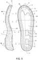
- FIG. 3depicts a cross-sectional view of a sole and a top plan view of the sole as molded with a nylon stabilizer.
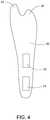
- FIG. 4depicts a stabilizer
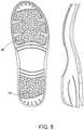
- FIG. 5depicts a side view and a bottom view of a molded sole having a bottom traction pattern.
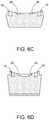
- FIGS. 6A-6Ddepict a cross-sectional views of a molded sole.
- the solecomprises an ethylene vinyl acetate (EVA) frame, a nylon rigid member, and a thermoplastic polyurethane (TPU) filler, wherein through a compression molding process, the materials are molded together to form a sole being lighter than prior generation soles for the same shoes.
- EVAethylene vinyl acetate
- TPUthermoplastic polyurethane
- the weight savingsis generated by manufacturing the sole with a lightweight material, for example, EVA, and by incorporating only necessary amounts of TPU and nylon for support per sole. Therefore, based upon the processes described herein, the resultant sole, once formed and attached to an appropriate upper, is approximately 10 ounces lighter. Such weight reduction greatly reduces energy expenditure and fatigue to someone wearing a shoe or a clog on a daily basis.
- the general shape of the solemaintains the traditional profile of a shoe sole, having a forefoot, a midfoot (arch) and heel sections.
- the solemay comprised a raised heel for aesthetics and for comfort, with the heel being slightly higher than the forefoot.
- the materials, the process, and the resulting soleare entirely transformed into a new product having significant weight savings over prior iterations of the sole.
- a frame 1having an inscribed channel 3 positioned inside the outer edge 8 of the sole.
- the channelis within the boundary of the frame, along the perimeter, but have some frame material between the frame outer edge 8 and the channel outer edge 5 .
- the channel 3is a recess generally following the perimeter of the frame and has a depth of about 3-15 mm and is defined as the width 7 between the outer edge of the channel 5 and the interior edge 6 of the channel.
- the channel 3is inscribed along the entirety of the outer edge 8 of the frame 1 , to some extent, similar to a moat around a castle or around the perimeter of the sole.
- the channel 3is defined to accept a rigid material within the channel, wherein upon construction of the shoe, the upper is stapled into the rigid material of the channel.
- the frame 1is preferably molded EVA.
- other polymer materials, plastics, and the likemay be utilized.
- certain viscosities of polyurethanehave properties similar to EVA, namely, lightweight, low to medium density and have flexibility.
- Certain materialshave greater flexibility and compression than others, and the particular choice can be made based on the ultimate intended use of the sole, or whether it will have an added rubber or traction material added to the bottom face.
- FIG. 1Further depicted in FIG. 1 is a heel support recess 2 and a plurality of arch recesses 4 .
- the heel support recess 2provides an access point for inserting a rigid material into the recess. This rigid material is utilized to then accept a fastening device to assist in securing the upper or to secure the last, which is utilized in forming the shape of the upper during manufacturing.
- the arch recesses 4extend on the upper face 9 , from the top face of the sole to the middle of the sole, a depth of about 3-20 mm, but do not extend completely through the sole. These arch recesses 4 provide for a weight reduction, simply by evacuation of material. However, they also provide for additional support and rigidity to the frame 1 , when for example it is manufactured with an EVA material.
- the supportis created as the EVA material comprises a soft, compressible foam core that is surrounded by a skin, wherein the skin has increased rigidity as compared to the underlying foam. Accordingly, each recess increases the amount of the skin material in portions of the frame thus modifying the rigidity and structure of the frame at those points. This increases the stability of the EVA frame in the locations of the recesses, and thus increases the stability of the sole once molded.
- FIG. 2details a step in the manufacturing process when a rigid material 10 is inserted into the channel 3 .
- the rigid material 10unlike typical polyurethane, is not in liquid form before pressing, but is sufficiently granular or pliable in its uncured form to be inserted into the cavities in the frame 1 . Accordingly, the rigid material 10 must be inserted into the channel 3 before it can be molded and compressed to form a portion of the sole.
- the rigid materialis TPU, and, once cured is sufficiently rigid and possesses properties wherein a fastening device (such as a nail or staple) can be embedded into the material and hold the fastening device in place.
- a fastening devicesuch as a nail or staple
- the upperto be stapled or nailed to the sole, where the fastening device penetrates the upper and into the TPU channel.
- the TPUbecomes affixed to the EVA material of the frame, through pressure and bonding.
- adhesivesmay assist this affixing process, however chemical bonding and curing is sufficient in most circumstances.
- Additional rigid materialis positioned within the heel support recess 2 , for example TPU, and thus further comprises the heel TPU material 11 , and one also placed across the arch, the arch TPU material 12 , adjacent to the arch recesses 4 . These positions are necessary to provide additional portions of the sole that can accept a fastening device for manufacturing and/or fastening or supporting a support member 20 .
- the rigid materialis TPU.
- the TPUcan be exchanged for another material that can be sufficiently molded and bonded to an EVA material, and also contain sufficient properties to impart rigidity to the channel of the sole as well as having the ability to accept a fastening device, such as a nail or staple. Indeed, the ability to receive the fastening device, and then hold in the upper to the sole is a primary function of the rigid material.
- materials other than TPUsuch as rigid EVA, and other plastics, polymers, urethanes, or combinations thereof, possess the appropriate physical properties to replace TPU as described in the embodiments herein.
- FIG. 3depicts a side profile and a top perspective view of the sole after molding is completed.
- the left side of FIG. 3depicts a side cut-through view of a sole. Depicted on the bottom are the traction pads 40 and 42 . Also depicted at the top of the sole is the channel 3 , which is filled with a rigid material 10 . Furthermore, a support 20 is depicted in certain portions of the sole.
- the support 20Depicted on the right side of FIG. 3 is the support 20 , which is embedded and bonded to the frame 1 .
- the arch material 12 and the heel material 11are positioned to fit within a single rectangular arch hole 22 and a single rectangular heel hole 21 of the support 20 .
- the support 20is intended to be a substantially rigid component, made of a thin and lightweight material, wherein the rigidity of the material can be suitably combined to the sole 1 to increase the rigidity of the sole 1 after compression.
- the support 20is necessary because the material that comprises the majority of the frame does not contain sufficient rigidity. Accordingly, to replicate the feel and support found in more rigid materials and soles, a support 20 is affixed to the frame.
- the support 20has a curvature along the longitudinal axis to match the contours of the foot when molded, as well as the angle based on the rise of the heel. As can be seen in FIGS.
- the support 20has a heel portion and an arch portion, the entire arch portion only has the single rectangular arch hole 22 and the entire heel portion only has the single rectangular heel hole 21 .
- the single rectangular heel hole 21 and single rectangular arch hole 22are arranged in alignment with each other and along a longitudinal direction of the shoe sole.
- two extended protrusionsare positioned at the front of the support 20 on either side of the lateral axis at the toe portion of the sole representing an interior protrusion 23 and an exterior protrusion 24 . These protrusions increase the rigidity of the molded sole at about the ball of the foot and the corresponding outside of the foot.
- the support 20is molded to take the particular shape of the sole based on the mold utilized.
- the support 20has perimeter dimensions to fit within the inner edge of the inscribed channel, and is about 0.5-5 mm in thickness, usually about 0.5-2 mm in thickness.
- the supportis made of nylon.
- Nylonis suitable for the support 20 , as it can be advantageously modified to take up the shape of the shoe upon molding.
- other suitable rigid and lightweight materialsmay be suitably exchanged, e.g. polymers, plastics,
- an adhesiveis applied to the bottom of the support 20 , it is then adhered to the upper face 9 of the frame 1 , and placed so that the arch hole 22 and the heel hole 21 are positioned over the heel TPU material 11 and the arch TPU material 12 from FIG. 2 .
- these TPU materialsfill the arch hole 22 and heel hole 21 and the adhesive further assists to secure the support 20 to the frame.
- the TPU material in the heelmolds into the heel support recess 2 and also expands into the heel plate hole 21 in the nylon plate.
- the arch material 12is compressed into the arch hole 22 in the nylon plate.
- FIG. 4particularly depicts a support 20 not affixed or molded to the frame 1 . Depicted is the heel hole 21 , the arch hole 22 , and the interior protrusion 23 and exterior protrusion 24 . This support 20 , is then affixed or molded to the upper face 9 of the frame 1 .
- FIG. 5depicts a rubber bottom sole comprising rubber sections 40 and 42 .
- any number of bottom materialsmay be added to the sole to increase traction, stability, support, abrasion rate, and wear.
- the soleis manufactured to not require an additional bottom material on the sole.
- FIGS. 6A-6Ddepict different cross-sectional cuts of the sole manufactured with the frame as EVA material, TPU as the rigid material, and nylon as the support 20 .
- FIG. 9Ashows the channel 3 and that the rigid material 10 has completely filled the channel and is flush with the top of the sole. Additionally, a small portion of the nylon support 20 is depicted near the center of the sole.
- FIG. 6Bprovides a further image of the sole and again clearly depicts the channel 3 along both sides of the sole and the rigid material 10 filled therein.
- FIGS. 6C and 6Dfurther depict cross-sections of a sole identifying sections wherein TPU is positioned in and around the EVA material of the sole.
- the frameis appropriately utilized in a process for manufacturing a shoe, such as a clog, wherein the frame is molded with a lightweight EVA material, a rubber bottom can be affixed to the bottom of the sole after molding, and a channel provides for an access point for molding a rigid material, such as TPU, for adhering an upper to the EVA sole.
- a support 20Positioned on the top of the frame is a support 20 that provides for stability and shape to the finished sole.
- An uppercan be fastened to the sole by stapling or nailing the upper into the TPU channel that is molded into the sole.
- a further embodimentis directed to a process for manufacturing a lightweight sole, having a lightweight frame, at least one channel in said frame comprising a rigid material capable of maintaining a solid object or fastener inserted thereto, wherein the rigid material has greater rigidity than lightweight frame, but is not brittle.
- the lightweight materialis EVA and the rigid material is TPU, however, those of skill in the art will recognize additional materials that are suitable for such application.
- a supportis further adhered to the top of the frame and all components are molded together forming a sole.
- a traction padcan be optionally applied once the sole is molded, e.g. the pads 40 and 42 . Rubber material, or other plastic or polymers have appropriate levels of traction, abrasion, and flexibility for the sole.
- a process for molding a solecomprises the following steps:
- the processuses EVA as the frame, TPU as the rigid material, and nylon as the stabilizer.
- the further piece of rigid material into the single large recess at the central portion of the heel 11 and also a second rigid material 12 overlying at least one of the arch recesses 4correspond to the openings in the stabilizer 20 .
- an appropriate rubber, plastic, or leather materialcan be optionally added to the bottom of the sole and an upper can be fixed to the sole via a fastening mechanism, such as being stapled or nailed into the rigid material in the inscribed channel.
- a lastis positioned within the upper and heat set to create the final shape of the upper.
- EVA materialin a clog style shoe provides for a significant weight savings over the prior art.
- the EVA materialnecessitates the use of additional features to give appropriate stability to the sole.
- the rigid materiale.g. TPU material within the channel is necessary to provide for a sufficiently rigid section of the sole to allow the upper to be secured to the sole.
- the above manufactured soleis then utilized for manufacturing a completed shoe.
- the soleis trimmed for excess material before adding the upper to the sole.
- a lastcan be affixed to the sole and an upper affixed to the rigid material in the channel.
- the upperis then cured or molded to give it the appropriate shape and then the last can be removed.
- a traction pad( 40 and 42 ) can be added to the heel and toe portion of the sole.
Landscapes
- Engineering & Computer Science (AREA)
- Mechanical Engineering (AREA)
- Chemical & Material Sciences (AREA)
- Materials Engineering (AREA)
- Footwear And Its Accessory, Manufacturing Method And Apparatuses (AREA)
Abstract
Description
Claims (7)
Priority Applications (1)
| Application Number | Priority Date | Filing Date | Title |
|---|---|---|---|
| US15/601,643US11154114B2 (en) | 2016-05-20 | 2017-05-22 | Lightweight thermoplastic soles |
Applications Claiming Priority (2)
| Application Number | Priority Date | Filing Date | Title |
|---|---|---|---|
| US201662339555P | 2016-05-20 | 2016-05-20 | |
| US15/601,643US11154114B2 (en) | 2016-05-20 | 2017-05-22 | Lightweight thermoplastic soles |
Publications (2)
| Publication Number | Publication Date |
|---|---|
| US20170332728A1 US20170332728A1 (en) | 2017-11-23 |
| US11154114B2true US11154114B2 (en) | 2021-10-26 |
Family
ID=60329628
Family Applications (1)
| Application Number | Title | Priority Date | Filing Date |
|---|---|---|---|
| US15/601,643Active2037-10-02US11154114B2 (en) | 2016-05-20 | 2017-05-22 | Lightweight thermoplastic soles |
Country Status (2)
| Country | Link |
|---|---|
| US (1) | US11154114B2 (en) |
| CN (1) | CN107397295A (en) |
Families Citing this family (4)
| Publication number | Priority date | Publication date | Assignee | Title |
|---|---|---|---|---|
| CN107397295A (en)* | 2016-05-20 | 2017-11-28 | 丹斯克有限公司 | The thermoplasticity sole of light weight |
| CN113519974B (en)* | 2021-05-28 | 2023-02-03 | 浙江科曼奇生物科技股份有限公司 | Sole and forming method thereof |
| US20240114995A1 (en)* | 2022-10-07 | 2024-04-11 | Jolley Enterprises, Llc | Slides and components thereof |
| CH720399A1 (en)* | 2022-12-23 | 2024-06-28 | X Tech Swiss Gmbh | Shoe structure |
Citations (49)
| Publication number | Priority date | Publication date | Assignee | Title |
|---|---|---|---|---|
| US4030213A (en) | 1976-09-30 | 1977-06-21 | Daswick Alexander C | Sporting shoe |
| US4041619A (en) | 1975-03-21 | 1977-08-16 | Peter Sapper | Shoe |
| US4302892A (en)* | 1980-04-21 | 1981-12-01 | Sunstar Incorporated | Athletic shoe and sole therefor |
| USRE31173E (en) | 1976-09-30 | 1983-03-15 | Sporting shoe | |
| US4408402A (en)* | 1982-08-05 | 1983-10-11 | Looney Judy A | Supportive shoe and insert |
| US4667423A (en)* | 1985-05-28 | 1987-05-26 | Autry Industries, Inc. | Resilient composite midsole and method of making |
| US5131173A (en) | 1987-05-15 | 1992-07-21 | Adidas Ag | Outsole for sports shoes |
| US5147589A (en) | 1991-07-02 | 1992-09-15 | Chang Shui P | Method of making a shoe sole of thermoplastic materials |
| US5503786A (en) | 1995-08-15 | 1996-04-02 | Yang; Kuo-Nan | Method for forming air chamber in shoe sole |
| US5554694A (en) | 1990-12-21 | 1996-09-10 | Crow; William R. | Performance enhancing athletic shoe components and methods |
| US5560877A (en) | 1995-07-21 | 1996-10-01 | Taiwan Footwear Research Institute | Process for manufacturing an ethylene vinyl acetate sole using first and second mold units |
| US5695850A (en) | 1993-01-29 | 1997-12-09 | Crow; William R. | Performance enhancing athletic shoe components and methods |
| US5718064A (en) | 1994-04-04 | 1998-02-17 | Nine West Group Inc. | Multi-layer sole construction for walking shoes |
| US5868981A (en) | 1996-04-19 | 1999-02-09 | Finproject--S.p.A. | Injection moulding process for soles in expansible and cross-linking "Eva"b |
| US6045733A (en) | 1998-09-24 | 2000-04-04 | Pao Chen Corporation | Method for manufacturing a shoe sole having two densities |
| US6120880A (en) | 1995-03-23 | 2000-09-19 | Crow; William R. | Performance enhancing athletic shoe components and methods |
| US6129798A (en) | 1999-12-14 | 2000-10-10 | Shun-Feng Lu | Process for manufacturing an ethylene vinyl acetate insole |
| US6226894B1 (en) | 1998-05-11 | 2001-05-08 | R. G. Barry Corporation | Slipper and method for manufacturing slipper |
| US6238602B1 (en) | 1999-12-14 | 2001-05-29 | Kun-Chung Liu | Two-stage forming process for producing an expanded sole |
| US6516241B1 (en) | 1998-06-30 | 2003-02-04 | Reebok International Ltd. | Method for gauging a mold cavity for injection molding |
| US6540864B1 (en) | 1999-01-13 | 2003-04-01 | Cheng-Hsian Chi | Method of making a shoe having a foamed insole with peripheral pattern |
| US6589630B1 (en) | 1995-03-23 | 2003-07-08 | William R. Crow | Performance enhancing shoe components and methods |
| KR200319548Y1 (en)* | 2003-04-07 | 2003-07-12 | 강신석 | Cushion footwear |
| US6681500B2 (en) | 1998-06-25 | 2004-01-27 | Geox S.P.A. | Vapor-permeable waterproof sole for shoes |
| EP1559337A1 (en) | 2004-01-28 | 2005-08-03 | Rottefella AS | Outsole for a sports shoe, preferably for cross-country skiing or telemark |
| US20070017122A1 (en)* | 2005-07-22 | 2007-01-25 | Craig Feller | Footwear sole with forefoot stabilizer, ribbed shank, and layered heel cushioning |
| US20070107264A1 (en) | 2005-11-15 | 2007-05-17 | Nike, Inc. | Flexible shank for an article of footwear |
| CN101402760A (en) | 2008-08-25 | 2009-04-08 | 牟海妲 | Materials for making shoe soles and processing method |
| US20100031531A1 (en)* | 2008-08-06 | 2010-02-11 | Nike, Inc. | Customization of Inner Sole Board |
| US7685740B2 (en) | 2006-07-13 | 2010-03-30 | Nike, Inc. | Dance shoe |
| US20100098797A1 (en) | 2008-10-16 | 2010-04-22 | Davis Carrie L | Mold assembly for midsole and method of manufaturing same |
| US20100107448A1 (en) | 2008-10-08 | 2010-05-06 | Nike, Inc. | Article of Footwear for Dancing |
| US20100251565A1 (en) | 2009-04-01 | 2010-10-07 | Reebok International Ltd. | Training Footwear |
| US20110126422A1 (en) | 2009-12-02 | 2011-06-02 | Brown Shoe Company, Inc. | Shoe sole with compressible protruding element |
| CN102215710A (en) | 2008-10-10 | 2011-10-12 | 耐克国际有限公司 | Article of footwear with a midsole structure |
| US8246881B2 (en) | 2009-09-02 | 2012-08-21 | Nike, Inc. | Method of manufacturing sole assembly for article of footwear |
| US8266825B2 (en) | 2008-06-11 | 2012-09-18 | Zurinvest Ag | Shoe sole element |
| US8307569B2 (en) | 2009-04-01 | 2012-11-13 | Reebok International Limited | Training footwear |
| US20130036627A1 (en) | 2011-08-10 | 2013-02-14 | Tee L. Wan | Article of footwear formed from two preforms and method and mold for manufacturing same |
| US20130291409A1 (en)* | 2012-04-13 | 2013-11-07 | Adidas Ag | Soles for sports shoes |
| KR20140104210A (en)* | 2013-02-20 | 2014-08-28 | 주식회사 영원아웃도어 | Shoe sole for shock absorption and method of producing the same |
| WO2014143732A1 (en) | 2013-03-15 | 2014-09-18 | Crocs, Inc. | Methods of manufacturing an article of footwear including sintering a copolymer powder |
| US20140259801A1 (en)* | 2013-03-15 | 2014-09-18 | New Balance Athletic Shoe, Inc. | Multi-Density Sole Elements, and Systems and Methods for Manufacturing Same |
| CN104379011A (en) | 2012-05-30 | 2015-02-25 | 耐克创新有限合伙公司 | Sole assembly for an article of footwear including a central support structure |
| US9003677B2 (en) | 2010-04-20 | 2015-04-14 | Crocs, Inc. | System and method for toning footwear |
| US9321200B2 (en) | 2007-02-09 | 2016-04-26 | Nike, Inc. | Method for making laminate |
| WO2016092353A1 (en) | 2014-12-12 | 2016-06-16 | Harald Beck | Modular insert system for shoe soles |
| US20160270475A1 (en)* | 2015-03-19 | 2016-09-22 | Nike, Inc. | Multi-Density Midsole and Plate System |
| US20170332728A1 (en)* | 2016-05-20 | 2017-11-23 | Dansko, Llc | Lightweight Thermoplastic Soles |
- 2017
- 2017-05-22CNCN201710364511.5Apatent/CN107397295A/enactivePending
- 2017-05-22USUS15/601,643patent/US11154114B2/enactiveActive
Patent Citations (51)
| Publication number | Priority date | Publication date | Assignee | Title |
|---|---|---|---|---|
| US4041619A (en) | 1975-03-21 | 1977-08-16 | Peter Sapper | Shoe |
| USRE31173E (en) | 1976-09-30 | 1983-03-15 | Sporting shoe | |
| US4030213A (en) | 1976-09-30 | 1977-06-21 | Daswick Alexander C | Sporting shoe |
| US4302892A (en)* | 1980-04-21 | 1981-12-01 | Sunstar Incorporated | Athletic shoe and sole therefor |
| US4408402A (en)* | 1982-08-05 | 1983-10-11 | Looney Judy A | Supportive shoe and insert |
| US4667423A (en)* | 1985-05-28 | 1987-05-26 | Autry Industries, Inc. | Resilient composite midsole and method of making |
| US5131173A (en) | 1987-05-15 | 1992-07-21 | Adidas Ag | Outsole for sports shoes |
| US5554694A (en) | 1990-12-21 | 1996-09-10 | Crow; William R. | Performance enhancing athletic shoe components and methods |
| US5147589A (en) | 1991-07-02 | 1992-09-15 | Chang Shui P | Method of making a shoe sole of thermoplastic materials |
| US5695850A (en) | 1993-01-29 | 1997-12-09 | Crow; William R. | Performance enhancing athletic shoe components and methods |
| US5718064A (en) | 1994-04-04 | 1998-02-17 | Nine West Group Inc. | Multi-layer sole construction for walking shoes |
| US6120880A (en) | 1995-03-23 | 2000-09-19 | Crow; William R. | Performance enhancing athletic shoe components and methods |
| US6589630B1 (en) | 1995-03-23 | 2003-07-08 | William R. Crow | Performance enhancing shoe components and methods |
| US5560877A (en) | 1995-07-21 | 1996-10-01 | Taiwan Footwear Research Institute | Process for manufacturing an ethylene vinyl acetate sole using first and second mold units |
| US5503786A (en) | 1995-08-15 | 1996-04-02 | Yang; Kuo-Nan | Method for forming air chamber in shoe sole |
| US5868981A (en) | 1996-04-19 | 1999-02-09 | Finproject--S.p.A. | Injection moulding process for soles in expansible and cross-linking "Eva"b |
| US6226894B1 (en) | 1998-05-11 | 2001-05-08 | R. G. Barry Corporation | Slipper and method for manufacturing slipper |
| US6681500B2 (en) | 1998-06-25 | 2004-01-27 | Geox S.P.A. | Vapor-permeable waterproof sole for shoes |
| US6516241B1 (en) | 1998-06-30 | 2003-02-04 | Reebok International Ltd. | Method for gauging a mold cavity for injection molding |
| US6045733A (en) | 1998-09-24 | 2000-04-04 | Pao Chen Corporation | Method for manufacturing a shoe sole having two densities |
| US6540864B1 (en) | 1999-01-13 | 2003-04-01 | Cheng-Hsian Chi | Method of making a shoe having a foamed insole with peripheral pattern |
| US6238602B1 (en) | 1999-12-14 | 2001-05-29 | Kun-Chung Liu | Two-stage forming process for producing an expanded sole |
| US6129798A (en) | 1999-12-14 | 2000-10-10 | Shun-Feng Lu | Process for manufacturing an ethylene vinyl acetate insole |
| KR200319548Y1 (en)* | 2003-04-07 | 2003-07-12 | 강신석 | Cushion footwear |
| EP1559337A1 (en) | 2004-01-28 | 2005-08-03 | Rottefella AS | Outsole for a sports shoe, preferably for cross-country skiing or telemark |
| US20070017122A1 (en)* | 2005-07-22 | 2007-01-25 | Craig Feller | Footwear sole with forefoot stabilizer, ribbed shank, and layered heel cushioning |
| US20070107264A1 (en) | 2005-11-15 | 2007-05-17 | Nike, Inc. | Flexible shank for an article of footwear |
| US7685740B2 (en) | 2006-07-13 | 2010-03-30 | Nike, Inc. | Dance shoe |
| US9321200B2 (en) | 2007-02-09 | 2016-04-26 | Nike, Inc. | Method for making laminate |
| US8266825B2 (en) | 2008-06-11 | 2012-09-18 | Zurinvest Ag | Shoe sole element |
| US20100031531A1 (en)* | 2008-08-06 | 2010-02-11 | Nike, Inc. | Customization of Inner Sole Board |
| CN101402760A (en) | 2008-08-25 | 2009-04-08 | 牟海妲 | Materials for making shoe soles and processing method |
| US20100107448A1 (en) | 2008-10-08 | 2010-05-06 | Nike, Inc. | Article of Footwear for Dancing |
| CN102215710A (en) | 2008-10-10 | 2011-10-12 | 耐克国际有限公司 | Article of footwear with a midsole structure |
| US20100098797A1 (en) | 2008-10-16 | 2010-04-22 | Davis Carrie L | Mold assembly for midsole and method of manufaturing same |
| US8307569B2 (en) | 2009-04-01 | 2012-11-13 | Reebok International Limited | Training footwear |
| US20100251565A1 (en) | 2009-04-01 | 2010-10-07 | Reebok International Ltd. | Training Footwear |
| US8424221B2 (en) | 2009-04-01 | 2013-04-23 | Reebok International Limited | Training footwear |
| US8246881B2 (en) | 2009-09-02 | 2012-08-21 | Nike, Inc. | Method of manufacturing sole assembly for article of footwear |
| US20110126422A1 (en) | 2009-12-02 | 2011-06-02 | Brown Shoe Company, Inc. | Shoe sole with compressible protruding element |
| US9003677B2 (en) | 2010-04-20 | 2015-04-14 | Crocs, Inc. | System and method for toning footwear |
| US20130036627A1 (en) | 2011-08-10 | 2013-02-14 | Tee L. Wan | Article of footwear formed from two preforms and method and mold for manufacturing same |
| US20130291409A1 (en)* | 2012-04-13 | 2013-11-07 | Adidas Ag | Soles for sports shoes |
| CN104379011A (en) | 2012-05-30 | 2015-02-25 | 耐克创新有限合伙公司 | Sole assembly for an article of footwear including a central support structure |
| KR20140104210A (en)* | 2013-02-20 | 2014-08-28 | 주식회사 영원아웃도어 | Shoe sole for shock absorption and method of producing the same |
| WO2014143732A1 (en) | 2013-03-15 | 2014-09-18 | Crocs, Inc. | Methods of manufacturing an article of footwear including sintering a copolymer powder |
| US20140259801A1 (en)* | 2013-03-15 | 2014-09-18 | New Balance Athletic Shoe, Inc. | Multi-Density Sole Elements, and Systems and Methods for Manufacturing Same |
| WO2016092353A1 (en) | 2014-12-12 | 2016-06-16 | Harald Beck | Modular insert system for shoe soles |
| US20170332727A1 (en)* | 2014-12-12 | 2017-11-23 | Harald Beck | Modular Insert System for Shoe Soles |
| US20160270475A1 (en)* | 2015-03-19 | 2016-09-22 | Nike, Inc. | Multi-Density Midsole and Plate System |
| US20170332728A1 (en)* | 2016-05-20 | 2017-11-23 | Dansko, Llc | Lightweight Thermoplastic Soles |
Non-Patent Citations (1)
| Title |
|---|
| Office Action dated Aug. 20, 2020 issued in Chinese Patent Application No. 201710364511.5. |
Also Published As
| Publication number | Publication date |
|---|---|
| CN107397295A (en) | 2017-11-28 |
| US20170332728A1 (en) | 2017-11-23 |
Similar Documents
| Publication | Publication Date | Title |
|---|---|---|
| US9510647B1 (en) | High heel shoe | |
| US11154114B2 (en) | Lightweight thermoplastic soles | |
| EP2874514B1 (en) | Sole plate assembly and method of making | |
| US9744734B2 (en) | Sole assembly with plural portions that cooperatively define chamber | |
| US8557157B2 (en) | Method of manufacturing an article of footwear having a direct attach sole component | |
| US20120279089A1 (en) | Method for fabricating a footwear sole | |
| US20080148599A1 (en) | Footwear inserts, including midsoles, sockliners, footbeds and/or upper components using granular ethyl vinyl acetate (EVA) and method of manufacture | |
| US10506845B2 (en) | Rubber shoe sole, material, and methods for manufacturing the same | |
| US9743711B2 (en) | Sole assembly with plural portions that cooperatively define chamber | |
| CA1107497A (en) | Insoles for skate boots | |
| US20170231320A1 (en) | Fitting system and method for customizable footwear | |
| EP2337469B1 (en) | Shoe having a midsole with heel support | |
| CN104320986B (en) | Customized insole and method of making same | |
| CN105228817B (en) | Method of forming a two-material midsole | |
| KR101641951B1 (en) | Mid-sole for safety shoes within penetration resistant insert and it's manufacturing process, safety shoes used it | |
| EP3402359B1 (en) | Sole structure for an article of footwear, comprising an outer sole component with a co-molded flex modifier component, and method of making said sole structure | |
| US20200375312A1 (en) | A sole for a shoe | |
| CN111838881A (en) | Article of footwear | |
| US20180368512A1 (en) | Fitting system and method for customizable footwear | |
| US4372525A (en) | Insole, apparatus for molding and method of making shoes | |
| KR101909221B1 (en) | Manufacture method insole for shoes | |
| KR20130056164A (en) | Manufacturing method of supporting device for sole of the foot and supporting device | |
| US20120304490A1 (en) | Orthotic insert and method of making the same | |
| EP1504688A1 (en) | Composite rubber plate | |
| KR20120017781A (en) | How to make shoe insole |
Legal Events
| Date | Code | Title | Description |
|---|---|---|---|
| AS | Assignment | Owner name:BANK OF AMERICA, N.A., AS ADMINISTRATIVE AGENT, CONNECTICUT Free format text:SECURITY INTEREST;ASSIGNOR:DANSKO, LLC;REEL/FRAME:045657/0117 Effective date:20180427 Owner name:BANK OF AMERICA, N.A., AS ADMINISTRATIVE AGENT, CO Free format text:SECURITY INTEREST;ASSIGNOR:DANSKO, LLC;REEL/FRAME:045657/0117 Effective date:20180427 | |
| STPP | Information on status: patent application and granting procedure in general | Free format text:RESPONSE TO NON-FINAL OFFICE ACTION ENTERED AND FORWARDED TO EXAMINER | |
| STPP | Information on status: patent application and granting procedure in general | Free format text:NON FINAL ACTION MAILED | |
| STPP | Information on status: patent application and granting procedure in general | Free format text:RESPONSE TO NON-FINAL OFFICE ACTION ENTERED AND FORWARDED TO EXAMINER | |
| STPP | Information on status: patent application and granting procedure in general | Free format text:FINAL REJECTION MAILED | |
| STPP | Information on status: patent application and granting procedure in general | Free format text:RESPONSE AFTER FINAL ACTION FORWARDED TO EXAMINER | |
| STPP | Information on status: patent application and granting procedure in general | Free format text:DOCKETED NEW CASE - READY FOR EXAMINATION | |
| STPP | Information on status: patent application and granting procedure in general | Free format text:RESPONSE TO NON-FINAL OFFICE ACTION ENTERED AND FORWARDED TO EXAMINER | |
| STPP | Information on status: patent application and granting procedure in general | Free format text:DOCKETED NEW CASE - READY FOR EXAMINATION | |
| STPP | Information on status: patent application and granting procedure in general | Free format text:NON FINAL ACTION MAILED | |
| STPP | Information on status: patent application and granting procedure in general | Free format text:RESPONSE TO NON-FINAL OFFICE ACTION ENTERED AND FORWARDED TO EXAMINER | |
| STPP | Information on status: patent application and granting procedure in general | Free format text:NOTICE OF ALLOWANCE MAILED -- APPLICATION RECEIVED IN OFFICE OF PUBLICATIONS | |
| STPP | Information on status: patent application and granting procedure in general | Free format text:PUBLICATIONS -- ISSUE FEE PAYMENT VERIFIED | |
| STCF | Information on status: patent grant | Free format text:PATENTED CASE | |
| MAFP | Maintenance fee payment | Free format text:PAYMENT OF MAINTENANCE FEE, 4TH YR, SMALL ENTITY (ORIGINAL EVENT CODE: M2551); ENTITY STATUS OF PATENT OWNER: SMALL ENTITY Year of fee payment:4 |