US11153875B2 - Apparatus and method for inter-band pairing of carriers for time division duplex transmit- and receive-switching and its application to multiplexing of different transmission time intervals - Google Patents
Apparatus and method for inter-band pairing of carriers for time division duplex transmit- and receive-switching and its application to multiplexing of different transmission time intervalsDownload PDFInfo
- Publication number
- US11153875B2 US11153875B2US14/567,985US201414567985AUS11153875B2US 11153875 B2US11153875 B2US 11153875B2US 201414567985 AUS201414567985 AUS 201414567985AUS 11153875 B2US11153875 B2US 11153875B2
- Authority
- US
- United States
- Prior art keywords
- grant
- carrier
- tti
- utilizing
- uplink
- Prior art date
- Legal status (The legal status is an assumption and is not a legal conclusion. Google has not performed a legal analysis and makes no representation as to the accuracy of the status listed.)
- Active, expires
Links
Images


Classifications
- H—ELECTRICITY
- H04—ELECTRIC COMMUNICATION TECHNIQUE
- H04B—TRANSMISSION
- H04B7/00—Radio transmission systems, i.e. using radiation field
- H04B7/24—Radio transmission systems, i.e. using radiation field for communication between two or more posts
- H04B7/26—Radio transmission systems, i.e. using radiation field for communication between two or more posts at least one of which is mobile
- H04B7/2615—Radio transmission systems, i.e. using radiation field for communication between two or more posts at least one of which is mobile using hybrid frequency-time division multiple access [FDMA-TDMA]
- H—ELECTRICITY
- H04—ELECTRIC COMMUNICATION TECHNIQUE
- H04L—TRANSMISSION OF DIGITAL INFORMATION, e.g. TELEGRAPHIC COMMUNICATION
- H04L5/00—Arrangements affording multiple use of the transmission path
- H04L5/0001—Arrangements for dividing the transmission path
- H04L5/0003—Two-dimensional division
- H04L5/0005—Time-frequency
- H04L5/0007—Time-frequency the frequencies being orthogonal, e.g. OFDM(A) or DMT
- H04L5/001—Time-frequency the frequencies being orthogonal, e.g. OFDM(A) or DMT the frequencies being arranged in component carriers
- H—ELECTRICITY
- H04—ELECTRIC COMMUNICATION TECHNIQUE
- H04L—TRANSMISSION OF DIGITAL INFORMATION, e.g. TELEGRAPHIC COMMUNICATION
- H04L5/00—Arrangements affording multiple use of the transmission path
- H04L5/14—Two-way operation using the same type of signal, i.e. duplex
- H—ELECTRICITY
- H04—ELECTRIC COMMUNICATION TECHNIQUE
- H04L—TRANSMISSION OF DIGITAL INFORMATION, e.g. TELEGRAPHIC COMMUNICATION
- H04L5/00—Arrangements affording multiple use of the transmission path
- H04L5/14—Two-way operation using the same type of signal, i.e. duplex
- H04L5/1469—Two-way operation using the same type of signal, i.e. duplex using time-sharing
- H—ELECTRICITY
- H04—ELECTRIC COMMUNICATION TECHNIQUE
- H04L—TRANSMISSION OF DIGITAL INFORMATION, e.g. TELEGRAPHIC COMMUNICATION
- H04L5/00—Arrangements affording multiple use of the transmission path
- H04L5/22—Arrangements affording multiple use of the transmission path using time-division multiplexing
- H04L5/26—Arrangements affording multiple use of the transmission path using time-division multiplexing combined with the use of different frequencies
- H04W72/042—
- H—ELECTRICITY
- H04—ELECTRIC COMMUNICATION TECHNIQUE
- H04W—WIRELESS COMMUNICATION NETWORKS
- H04W72/00—Local resource management
- H04W72/04—Wireless resource allocation
- H04W72/044—Wireless resource allocation based on the type of the allocated resource
- H04W72/0446—Resources in time domain, e.g. slots or frames
- H—ELECTRICITY
- H04—ELECTRIC COMMUNICATION TECHNIQUE
- H04W—WIRELESS COMMUNICATION NETWORKS
- H04W72/00—Local resource management
- H04W72/04—Wireless resource allocation
- H04W72/044—Wireless resource allocation based on the type of the allocated resource
- H04W72/0453—Resources in frequency domain, e.g. a carrier in FDMA
- H—ELECTRICITY
- H04—ELECTRIC COMMUNICATION TECHNIQUE
- H04W—WIRELESS COMMUNICATION NETWORKS
- H04W72/00—Local resource management
- H04W72/12—Wireless traffic scheduling
- H04W72/1257—
- H—ELECTRICITY
- H04—ELECTRIC COMMUNICATION TECHNIQUE
- H04W—WIRELESS COMMUNICATION NETWORKS
- H04W72/00—Local resource management
- H04W72/12—Wireless traffic scheduling
- H04W72/1263—Mapping of traffic onto schedule, e.g. scheduled allocation or multiplexing of flows
- H04W72/1268—Mapping of traffic onto schedule, e.g. scheduled allocation or multiplexing of flows of uplink data flows
- H—ELECTRICITY
- H04—ELECTRIC COMMUNICATION TECHNIQUE
- H04W—WIRELESS COMMUNICATION NETWORKS
- H04W72/00—Local resource management
- H04W72/12—Wireless traffic scheduling
- H04W72/1263—Mapping of traffic onto schedule, e.g. scheduled allocation or multiplexing of flows
- H04W72/1273—Mapping of traffic onto schedule, e.g. scheduled allocation or multiplexing of flows of downlink data flows
- H—ELECTRICITY
- H04—ELECTRIC COMMUNICATION TECHNIQUE
- H04W—WIRELESS COMMUNICATION NETWORKS
- H04W72/00—Local resource management
- H04W72/20—Control channels or signalling for resource management
- H04W72/23—Control channels or signalling for resource management in the downlink direction of a wireless link, i.e. towards a terminal
- H—ELECTRICITY
- H04—ELECTRIC COMMUNICATION TECHNIQUE
- H04W—WIRELESS COMMUNICATION NETWORKS
- H04W72/00—Local resource management
- H04W72/50—Allocation or scheduling criteria for wireless resources
- H04W72/535—Allocation or scheduling criteria for wireless resources based on resource usage policies
- H—ELECTRICITY
- H04—ELECTRIC COMMUNICATION TECHNIQUE
- H04L—TRANSMISSION OF DIGITAL INFORMATION, e.g. TELEGRAPHIC COMMUNICATION
- H04L1/00—Arrangements for detecting or preventing errors in the information received
- H04L1/08—Arrangements for detecting or preventing errors in the information received by repeating transmission, e.g. Verdan system
- H—ELECTRICITY
- H04—ELECTRIC COMMUNICATION TECHNIQUE
- H04W—WIRELESS COMMUNICATION NETWORKS
- H04W76/00—Connection management
- H04W76/10—Connection setup
- H04W76/15—Setup of multiple wireless link connections
Definitions
- Wireless communication networksare widely deployed to provide various communication services such as telephony, video, data, messaging, broadcasts, and so on.
- Such networkswhich are usually multiple access networks, support communications for multiple users by sharing the available network resources.
- the disclosureprovides a method, apparatus, and computer-readable medium having code for implementing wireless communication utilizing an algorithm for pairing inter-band carriers for transmit- and receive switching.
- a scheduling entitymay wirelessly communicate utilizing a first transmission time interval (TTI) over a first carrier, the first carrier being a time division duplex (TDD) carrier.
- TTItransmission time interval
- TDDtime division duplex
- the scheduling entitymay wirelessly communicate utilizing a second TTI different from the first TTI and at least partially overlapping the first TTI, over a second carrier paired with the first carrier but separated from the first carrier in frequency.
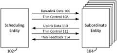
- FIG. 1is a block diagram conceptually illustrating an example of a scheduling entity communicating with one or more subordinate entities according to some embodiments.
- FIG. 2is a block diagram illustrating an example of a hardware implementation for a scheduling entity employing a processing system according to some embodiments.
- FIG. 3is a block diagram illustrating an example of a hardware implementation for a subordinate entity employing a processing system according to some embodiments.
- FIG. 10is a flow chart illustrating an example of multiplexing low latency downlink data with regular uplink data utilizing a thin control channel from the point of view of a scheduling entity, according to some embodiments.
- FIG. 21is a flow chart illustrating an example of multiplexing low latency downlink data with regular uplink data utilizing a thin control channel from the point of view of a scheduling entity, according to some embodiments.
- LTE networkscan provide end-to-end latency between a transmitting device and a receiving device on the order of 50 ms, with over-the-air latency for a particular packet being in the range of 10 ms.
- FIG. 2is a conceptual diagram illustrating an example of a hardware implementation for a scheduling entity 102 employing a processing system 214 .
- a processing system 214that includes one or more processors 204 .
- the apparatus 200may be any suitable radio transceiver apparatus, and in some examples, may be embodied by a base station (BS), a base transceiver station (BTS), a radio base station, a radio transceiver, a transceiver function, a basic service set (BSS), an extended service set (ESS), an access point (AP), a Node B, an eNode B (eNB), mesh node, relay, or some other suitable terminology.
- a base stationmay be referred to as a scheduling entity, indicating that the base station provides scheduling information to one or more subordinate entities.
- the processing system 214may be implemented with a bus architecture, represented generally by the bus 202 .
- the bus 202may include any number of interconnecting buses and bridges depending on the specific application of the processing system 214 and the overall design constraints.
- the bus 202links together various circuits including one or more processors (represented generally by the processor 204 ), a memory 205 , and computer-readable media (represented generally by the computer-readable medium 206 ).
- the bus 202may also link various other circuits such as timing sources, peripherals, voltage regulators, and power management circuits, which are well known in the art, and therefore, will not be described any further.
- a bus interface 208provides an interface between the bus 202 and a transceiver 210 .
- the transceiver 210provides a means for communicating with various other apparatus over a transmission medium.
- a user interface 212e.g., keypad, display, speaker, microphone, joystick
- the processor 204may include resource assignment and TTI control circuitry 241 , configured to generate, schedule, and modify a resource assignment or grant of time-frequency resources.
- the resource assignment and TTI control circuitry 241may further be configured to determine the TTI to utilize for uplink and downlink transmissions, e.g., whether data transmissions should utilize a first, long TTI, or a second, short TTI.
- the resource assignment and TTI control circuitry 241may operate in coordination with resource assignment and TTI control software 251 .
- the computer-readable mediummay also include, by way of example, a carrier wave, a transmission line, and any other suitable medium for transmitting software and/or instructions that may be accessed and read by a computer.
- the computer-readable medium 206may reside in the processing system 214 , external to the processing system 214 , or distributed across multiple entities including the processing system 214 .
- the computer-readable medium 206may be embodied in a computer program product.
- a computer program productmay include a computer-readable medium in packaging materials.
- the channel structuremay be applicable to an uplink data transmission, i.e., a transmission from a subordinate entity 104 to a scheduling entity 102 .
- this channel structureis not limited to such a scheme, but rather may be generalized to be applicable to any link where the receiving device is scheduling the traffic.
- the width of the thin control channel 406 in the frequency directionmay be reduced or minimized so as to reduce or minimize the amount of overhead utilized by the control channel 406 .
- all active userse.g., subordinate entities 104 including but not necessarily limited to the regular users 402
- the scheduling entity 102 that broadcasts the thin control channel 406may monitor (and, in some examples, buffer) the thin control channel 406 shown herein.
- each time slot, symbol, or unit of the thin control channel 406may correspond to the duration of a short TTI. That is, in some examples, the short TTI may correspond to the time duration of a single symbol. Some non-limiting examples of a short TTI may have a duration of 10 ⁇ s, 20 ⁇ s, 100 ⁇ s, or any other suitable duration that is shorter than the long TTI. In some examples, the long TTI may represent an integer multiple of short TTIs. In some examples, a common symbol duration may be utilized within both the long TTI and the short TTI, or in other examples, different symbol durations may be utilized within the long TTI and the short TTI.
- grant information directed to the requesting LoLat user 404may include information identifying the LoLat user 404 , identifying one or more time-frequency resources, modulation and coding schemes, transmission schemes, or any other suitable information relating to the granted resource for the requesting LoLat user 404 .
- the LoLat user 404transmits the LoLat scheduling request 409 , but all subordinate entities, including the regular users 402 , receive the uplink grant modification 408 .
- the regular users 402may be configured such that they are capable of decoding the uplink grant modification 408 relatively quickly, so that they can promptly cease transmitting (e.g., puncture their transmissions) during the re-allocated short TTI(s). In this way, the time-frequency resources may quickly be made available for the LoLat user 404 to transmit its LoLat symbols.
- Thin control channelssuch as the thin control channel 406 described above have been identified as an enabling feature for many potential uses.
- a communication systemcan be provided with low-latency data rate control, coordinated multi-point (CoMP) solutions, and improved access to unlicensed bands.
- CoMPcoordinated multi-point
- theseare merely some examples of features that may be enabled with the use of a thin control channel, and those of ordinary skill in the art will comprehend that other features may be enabled by way of the thin control channel.
- One relevant feature provided by the use of the thin control channelis opportunistic transmission/reception switching, wherein the thin control channel in one direction may be utilized to rapidly modify data communication in the other direction.
- a channel structureincorporates a pairing of a TDD carrier with a second carrier, wherein the TDD carrier and the second carrier may be in different bands from one another (inter-band carriers).
- the paired carrierprovides an inverse, conjugate, or complementary direction of communication as that of the TDD carrier, full-duplex communication can be achieved, at least in some of the time slots, by simultaneous utilization of an uplink direction of communication in one carrier and a downlink direction of communication in the other carrier.
- the paired carriermay be in a TDD band.
- the two paired TDD carriersmay implement conjugate or inverse duplexing, such that full duplex is achieved.
- This conjugate duplexinggenerally establishes that during some or all of the time slots or frames in one of the carriers, when those frames are configured for communication in one direction, then at that same time, a corresponding time slot or frame in the paired carrier is configured for communication in the other direction.
- paired carriers and fast (thin) control channelsamong other functions, rapid uplink/downlink switching and multiplexing can be achieved for TDD carriers in an efficient and effective manner.
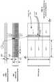
- FIG. 5illustrates one example of pairing a TDD carrier with an FDD carrier, providing for multiplexing of LoLat uplink transmissions with regular uplink transmissions (i.e., transmissions from a subordinate entity) on the TDD carrier.
- the TDD carrieris illustrated in much the same way as the TDD carrier in FIG. 4 , with uplink resources allocated to different users being represented by the large blocks spanning a long TTI.
- a subordinate entitye.g., a UE
- resources on an FDD bandare allocated, including an uplink component carrier and a downlink component carrier.
- time-frequency resources corresponding to the long TTImay be granted for uplink transmissions on the TDD carrier to one or more subordinate entities (e.g., Users A-F) by utilizing any suitable downlink grant channel (not necessarily one of the illustrated channels).
- subordinate entitiese.g., Users A-F
- any suitable downlink grant channelnot necessarily one of the illustrated channels.
- this subordinate entitymay transmit a LoLat scheduling request 507 on the thin feedback channel 506 on the FDD uplink component carrier.
- the LoLat scheduling request 507may utilize the short TTI, although this is not necessarily always the case.
- the LoLat grant 511 on the LoLat grant channel 510may be configured to inform the subordinate entity that transmitted the LoLat scheduling request (i.e., the LoLat user 504 ) of its granted time-frequency resources.
- the LoLat grant 511is shown as occupying a wider bandwidth than the UL grant modification 509 . This represents that, while the UL grant modification 509 may simply be a few bits representing the frequency resources that are being re-allocated away from a regular user 502 , and a number of short TTIs, the LoLat grant 511 may include more precise information relating to the LoLat resource assignment such as a user ID, the assignment information, a modulation and coding scheme, etc.
- the LoLat user 504also may have only a brief time from the receiving of its LoLat uplink grant 511 , and its transmission of LoLat uplink data. Accordingly, fast processing of the LoLat grant 511 and transmission utilizing the scheduled time-frequency resources would be beneficial and reduce latency.
- FIG. 6is described below in conjunction with a flow chart illustrated in FIG. 7 . That is, FIG. 7 is a flow chart illustrating an exemplary process 700 for resource assignment and re-assignment in accordance with some aspects of the present disclosure.
- the process 700is described from the point-of-view of a scheduling entity 501 , and may accordingly, as described in conjunction with FIG. 6 , be operational at the scheduling entity 102 described above in conjunction with FIGS. 1 and/or 2 .
- the process 700may be operational by a general purpose processor, a processing system 214 as described above and illustrated in FIG. 2 , or any suitable means for carrying out the described functions.
- the specific order of steps or blocks shown in FIG. 7is merely exemplary in nature, and in various aspects of the disclosure, these steps or blocks may occur in any suitable order, with some examples including two or more steps or blocks occurring simultaneously.
- the scheduling entity 501may transmit a first assignment or grant 510 of time-frequency resources to at least one subordinate entity on the FDD downlink component carrier. Any suitable control channel on the FDD downlink component carrier may be utilized for the first resource assignment, such as a downlink assignment channel.
- the first resource assignment 510may be configured to indicate which time-frequency resource or resources are assigned to the respective subordinate entities for regular transmissions of uplink data, that is, transmissions utilizing the long TTI.
- the scheduling entity 501may receive regular uplink data 512 on the TDD uplink carrier from the at least one subordinate entity (e.g., the subordinate entities 502 and 504 ) utilizing the long TTI.
- this regular uplink data 512may correspond to the transmissions from regular users 502 .
- regular uplink datamay optionally be transmitted from the second subordinate entity 504 , depending on the contents of the first resource assignment 510 and whether the second subordinate entity 504 is configured to transmit uplink data transmissions utilizing the long TTI.
- the second resource assignment 511may include information identifying the requesting subordinate entity 504 , and information identifying time-frequency resources granted on the TDD uplink carrier for the LoLat uplink transmission.
- the transmission of the uplink scheduling grant modification 509 at block 708 , and the transmission of the second resource assignment 511 at block 710may occur simultaneously. That is, these transmissions may be multiplexed, for example, utilizing different time-frequency resources. In other examples, these transmissions may be at different times, according to the details of a particular implementation.
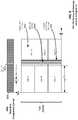
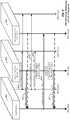
- FIG. 8illustrates another example of pairing a TDD carrier with an FDD carrier, providing for multiplexing of LoLat downlink transmissions (i.e., transmissions from a scheduling entity) with regular uplink transmissions (i.e., transmissions from a subordinate entity) on the TDD carrier.
- the TDD carrieris illustrated in much the same way as the TDD carrier in FIG. 4 , with uplink resources shown with a plurality of users (subordinate entities) transmitting “regular” uplink data utilizing a long TTI.
- the scheduling entitymay modify the scheduling assignment or grant of time-frequency resources, interrupting the ongoing uplink transmissions on the TDD carrier, with downlink transmissions on the TDD carrier.
- a control channel for controlling the user data carried on the TDD carrieris carried on an FDD downlink component carrier. That is, the FDD band includes in its downlink component carrier a LoLat grant channel 808 , in which a subordinate entity may receive information such as a LoLat downlink grant 810 .
- the scheduling entitymay determine to transmit LoLat downlink data on the TDD carrier. That is, at any time, one or more subordinate entities in communication with the scheduling entity, such as a LoLat user 804 , may come to need LoLat communication with the network, wherein more stringent latency requirements for communication are needed than the relatively long latency resulting from the communication by regular users utilizing the long TTI.
- the availability of the LoLat grant channel 808 on the FDD downlink component carriermay enable dynamic multiplexing of the traffic for one or more subordinate entities that desire low latency communication (hereinafter referred to as LoLat users 804 ), who can utilize a short TTI for data traffic, and the traffic for the regular users 802 , who utilize the long TTI for data traffic.
- LoLat users 804may enable dynamic multiplexing of the traffic for one or more subordinate entities that desire low latency communication (hereinafter referred to as LoLat users 804 ), who can utilize a short TTI for data traffic, and the traffic for the regular users 802 , who utilize the long TTI for data traffic.
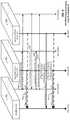
- FIG. 9is a call flow diagram illustrating an exemplary resource assignment and re-assignment procedure as it might occur in accordance with one example for multiplexing uplink and downlink data with different latency targets utilizing a TDD data carrier paired with FDD component carriers for control information.
- timemoves forward in the downward direction, and communication signals between the illustrated entities are denoted with arrows between the lines below the respective entities.
- a scheduling entity 801is in communication with a plurality of subordinate entities 104 , including a regular user 802 and a LoLat user 804 .
- Each entity 801 , 802 , and 804is configured for communication over a TDD carrier, and an FDD carrier.
- the respective TDD and FDD carriersare illustrated schematically with the two vertical lines extending down from each respective entity.
- FIG. 9is described below in conjunction with a flow chart illustrated in FIG. 10 .
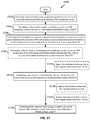
- FIG. 10is a flow chart illustrating an exemplary process 1000 for resource assignment and re-assignment utilizing a TDD data carrier paired with FDD component carriers for control information in accordance with some aspects of the present disclosure.
- the process 1000is described from the point-of-view of a scheduling entity 801 , and may accordingly, as described in conjunction with FIG. 9 , be operational at the scheduling entity 102 described above in conjunction with FIGS. 1 and/or 2 .
- the process 1000may be operational by a general purpose processor, a processing system 214 as described above and illustrated in FIG. 2 , or any suitable means for carrying out the described functions.
- the specific order of steps or blocks shown in FIG. 10is merely exemplary in nature, and in various aspects of the disclosure, these steps or blocks may occur in any suitable order, with some examples including two or more steps or blocks occurring simultaneously.
- the scheduling entity 801may transmit a first assignment or grant 820 of time-frequency resources to at least one subordinate entity on the FDD downlink component carrier. Any suitable control channel on the FDD downlink component carrier may be utilized for the first resource assignment, such as a downlink assignment channel.
- the first resource assignment 820may be configured to indicate which time-frequency resource or resources are assigned to the respective subordinate entities for regular transmissions of uplink data, that is, transmissions utilizing the long TTI.
- the scheduling entity 801may receive regular uplink data 822 on the TDD uplink carrier from the at least one subordinate entity (e.g., the subordinate entities 802 and 804 ) utilizing the long TTI.
- this regular uplink data 822may correspond to the transmissions from regular users 802 .
- regular uplink datamay optionally be transmitted from the second subordinate entity 804 , depending on the contents of the first resource assignment 820 and whether the second subordinate entity 804 is configured to transmit uplink data transmissions utilizing the long TTI.
- the blocks 1002 and 1004may repeat, or be iterated a plurality of times in various examples, as regular uplink data 822 may continue to be transmitted from the subordinate entities. However, at any given time, it may arise that the scheduling entity 801 may wish to transmit LoLat data to a particular subordinate entity (i.e., the LoLat user 804 ). Accordingly, at block 1006 , the scheduling entity 801 may transmit an assignment or grant 820 of time-frequency resources on the LoLat grant channel 808 on the FDD downlink component carrier, to at least one subordinate entity (e.g., the LoLat user 804 ).
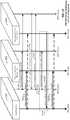
- FIG. 11illustrates yet another example of pairing a TDD carrier with an FDD carrier, providing for multiplexing of LoLat uplink transmissions (i.e., transmissions from a subordinate entity) with regular downlink transmissions (i.e., transmissions from a scheduling entity).
- the TDD carrieris illustrated in much the same way as the TDD carrier in FIG. 8 , with downlink resources shown with a scheduling entity transmitting “regular” downlink data utilizing a long TTI to plurality of users (subordinate entities).
- a control channel for enabling subordinate entities to quickly send information to the scheduling entityis carried on an FDD uplink component carrier. That is, the FDD band includes in its uplink component carrier a thin feedback channel 1116 in which the scheduling entity may receive feedback information from subordinate entities such as a LoLat scheduling request 1118 .
- time-frequency resources corresponding to the long TTImay be granted for downlink transmissions on the TDD carrier to one or more subordinate entities (e.g., Users A-F) by utilizing any suitable downlink grant channel (not necessarily one of the illustrated channels).
- subordinate entitiese.g., Users A-F
- any suitable downlink grant channelnot necessarily one of the illustrated channels.
- this subordinate entitymay transmit a LoLat scheduling request 1118 on the thin feedback channel 1116 on the FDD uplink component carrier.
- the LoLat scheduling request 1118may utilize the short TTI, although this is not necessarily always the case.
- the scheduling entitymay suspend its regular downlink data transmissions on the TDD carrier. That is, a gap or guard time 1106 may optionally be utilized when multiplexing LoLat uplink transmissions and regular downlink transmissions on the TDD carrier.
- this guard time 1106may for example compensate for any propagation delay or other air interface delay, allowing full completion of the regular downlink transmissions to all users in the service area prior to the time when the LoLat uplink transmissions commence on the TDD carrier.
- FIG. 12is described below in conjunction with a flow chart illustrated in FIG. 13 . That is, FIG. 13 is a flow chart illustrating an exemplary process 1300 for resource assignment and re-assignment utilizing a TDD data carrier paired with FDD component carriers for control information in accordance with some aspects of the present disclosure.
- the process 1300is described from the point-of-view of a scheduling entity 1101 , and may accordingly, as described in conjunction with FIG. 12 , be operational at the scheduling entity 102 described above in conjunction with FIGS. 1 and/or 2 .
- the process 1300may be operational by a general purpose processor, a processing system 214 as described above and illustrated in FIG. 2 , or any suitable means for carrying out the described functions.
- the specific order of steps or blocks shown in FIG. 13is merely exemplary in nature, and in various aspects of the disclosure, these steps or blocks may occur in any suitable order, with some examples including two or more steps or blocks occurring simultaneously.
- the blocks 1302 and 1304may repeat, or be iterated a plurality of times in various examples, as regular downlink data 1122 may continue to be transmitted to the subordinate entities. However, at any given time, it may arise that the subordinate entity 1104 (i.e., the LoLat user 1104 ) may wish to transmit LoLat uplink data to the scheduling entity 1101 . Accordingly, at block 1306 , the scheduling entity 1101 may receive a LoLat scheduling request 1118 on the thin feedback channel 1116 on the FDD uplink component carrier from the LoLat user 1104 (i.e., the second subordinate entity 1104 ).
- the LoLat scheduling request 1118may include information identifying the requesting subordinate entity 1104 , and including any pertinent information relating to the LoLat data desired to be transmitted.
- the scheduling entity 1101may transmit a second assignment or grant 1110 of time-frequency resources on a LoLat grant channel 1108 on the FDD downlink component carrier, to the requesting subordinate entity 1104 .
- the second resource assignment 1110may include information identifying the requesting subordinate entity 1104 , and information identifying time-frequency resources granted on the TDD uplink carrier for the LoLat uplink transmission.
- the scheduling entity 1101may receive the LoLat uplink data 1124 transmitted from the requesting subordinate entity 1104 utilizing the short TTI on the TDD carrier.
- the scheduling entity 1101may resume transmitting the regular downlink data 1122 on the TDD carrier, to one or more subordinate entities, such as the regular user 1102 utilizing the long TTI.
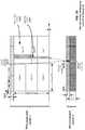
- FIG. 14illustrates one example of a pairing of two TDD component carriers (CC).
- CCcomponent carrier 1 or CC 1
- CC 2component carrier 2 or CC 2
- the horizontal axisrepresents time, and the vertical axis represents frequency (not to scale).
- Both CC 1 and CC 2are TDD carriers, wherein uplink time slots, indicated with a U, are time-multiplexed with downlink time slots, indicated with a D on each respective carrier.
- time slotsare identified as special time slots, and indicated with an S, described further below.
- a time slotmay correspond to any suitable duration of time, and may correspond to other nomenclature such as a transmission time interval (TTI), subframe, frame, symbol duration, etc.
- TTItransmission time interval
- subframesubframe
- framesymbol duration
- special time slots Sinsert a gap between the end of a downlink time slot D and the beginning of an uplink time slot U, so that the scheduling entity 102 and the subordinate entity 104 can maintain synchronization.
- the gapmay correspond to a time when neither uplink nor downlink communications occur.
- the length of the gap in the special time slot Scan be configured in accordance with the size of the cell.
- the special time slots S in one component carriercan be paired with any suitable time slot on its paired component carrier, including a downlink time slot D, an uplink time slot U, or another special time slot S.
- each of the special time slots S in one component carrier (CC 1 )may be mapped (e.g., time-aligned) to a respective downlink time slot in its paired component carrier (CC 2 ).
- CC 1a downlink time slot
- Uuplink time slot
- another special time slot Se.g., time-aligned
- the paired component carriersmay be inter-band carriers. That is, each of the component carriers CC 1 and CC 2 may lie in a different band from that of its paired component carrier.
- the RF functionality at a devicesuch as a scheduling entity 102 and a subordinate entity 104 can be improved, reducing interference and de-sense between the respective carriers.
- intra-band component carriersmay be utilized within the scope of the present disclosure; however, it may be beneficial in such case to choose component carriers that are as far apart in frequency as feasible.
- FIG. 15illustrates a conjugate pairing of component carriers in accordance with a further aspect of the present disclosure, configured to afford a degree of flexibility in the allocation of uplink and downlink time slots.
- a first TDD component carrier, CC 1having a wide bandwidth (e.g., 100 MHz) may be paired with a second TDD component carrier, CC 2 , having a narrow bandwidth (e.g., 10 MHz).
- the ratio between the bandwidth of the two component carriersneed not be the 10:1 ratio given here, but any suitable ratio may be utilized within the scope of the present disclosure.
- the choice of the ratiomay be made in accordance with characteristics of the traffic being carried on the uplink and downlink, such as the degree of asymmetry between uplink and downlink traffic. For example, traffic that is substantially heavier on the downlink side could be accommodated by deploying a larger number of downlink time slots on the wider bandwidth component carrier.
- the bandwidth of one or both of the TDD component carriersmay be selected according to the bandwidth desired or needed; and in some examples, the bandwidth of one or both of the TDD component carriers may be configurable by the scheduling entity or the subordinate entity.
- TDD-TDD Carrier PairingMultiplexing LoLat UL on Regular UL
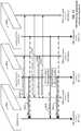
- FIG. 16illustrates one example of pairing a first TDD component carrier with a second TDD component carrier, providing for multiplexing of LoLat uplink transmissions with regular uplink transmissions (i.e., transmissions from a subordinate entity) on the primary TDD component carrier.
- the primary TDD component carrieris illustrated in much the same way as the TDD carrier in FIG. 5 , with uplink resources allocated to different users being represented by the large blocks spanning a long TTI.
- a subordinate entitye.g., a UE
- resources on a second TDD component carrierare allocated for use.
- control channels for controlling the uplink data transmissions on the primary TDD component carrierare carried on the secondary TDD component carrier.
- the secondary TDD component carrierincludes a thin control channel 1606 , which may carry uplink grant modification information 1608 that modifies an uplink resource grant corresponding to the subordinate entity (i.e., the regular user 1602 ) uplink transmission on the primary TDD component carrier.
- the secondary TDD component carrierincludes a LoLat grant channel 1610 , which may carry grant information 1612 for the subordinate entity that requests LoLat scheduling (i.e., the LoLat user 1604 ) to utilize in a LoLat uplink transmission on the primary TDD component carrier.
- the primary TDD component carrierincludes a thin feedback channel 1614 that a subordinate entity (i.e., the LoLat user 1604 ) can utilize to transmit information such as a LoLat scheduling request 1616 .
- a subordinate entityi.e., the LoLat user 1604
- time-frequency resources corresponding to the long TTImay be granted for uplink transmissions on the primary TDD component carrier to one or more subordinate entities (e.g., Users A-F) by utilizing any suitable downlink grant channel (not necessarily one of the illustrated channels).
- subordinate entitiese.g., Users A-F
- any suitable downlink grant channelnot necessarily one of the illustrated channels.
- this subordinate entitymay transmit a LoLat scheduling request 1616 on the thin feedback channel 1614 on the primary TDD component carrier.
- the LoLat scheduling request 1616may utilize the short TTI, although this is not necessarily always the case.
- the LoLat grant 1612 on the LoLat grant channel 1610may be configured to inform the subordinate entity that transmitted the LoLat scheduling request (i.e., the LoLat user 1604 ) of its granted time-frequency resources.
- the LoLat grant 1612is shown as occupying a wider bandwidth than the UL grant modification 1608 . This represents that, while the UL grant modification 1608 may simply be a few bits representing the frequency resources that are being re-allocated away from a regular user 1602 , and a number of short TTIs, the LoLat grant 1612 may include more precise information relating to the LoLat resource assignment such as a user ID, the assignment information, a modulation and coding scheme, etc.
- the LoLat user 1604may transmit its LoLat uplink transmission on the primary TDD component carrier, while other regular users 1602 (such as Users D, E, and F) may cease their uplink transmissions, resulting in an orthogonal multiple access scheme between regular and LoLat uplink transmissions on the TDD carrier.
- regular users 1602such as Users D, E, and F
- the regular users 1602e.g., subordinate entities 104
- the regular users 1602may benefit from having an ability to quickly decode the uplink grant modification 1608 . That is, the time from when the uplink grant modification 1608 is received at the regular user 1602 , until that user ceases its uplink transmissions, may be very short.
- the subordinate entity 104may be configured for a fast suspension of its uplink transmissions, e.g., by driving a zero input to a power amplifier within the transceiver 310 , or in another example, being capable of quickly turning off the power amplifier.
- the scheduling entity 1601may transmit a first assignment or grant 1620 of time-frequency resources to at least one subordinate entity on the secondary TDD component carrier. Any suitable control channel may be utilized for the first resource assignment, such as a downlink assignment channel.
- the first resource assignment 1620may be configured to indicate which time-frequency resource or resources are assigned to the respective subordinate entities for regular transmissions of uplink data, that is, transmissions utilizing the long TTI.
- the scheduling entity 1601may receive regular uplink data 1622 on the primary TDD component carrier from the at least one subordinate entity (e.g., the subordinate entities 1602 and 1604 ) utilizing the long TTI.
- the at least one subordinate entitye.g., the subordinate entities 1602 and 1604
- this regular uplink data 1622may correspond to the transmissions from regular users 1602 .
- regular uplink datamay optionally be transmitted from the second subordinate entity 1604 , depending on the contents of the first resource assignment 1620 and whether the second subordinate entity 1604 is configured to transmit uplink data transmissions utilizing the long TTI.
- the scheduling entity 1601may transmit an uplink scheduling grant modification 1608 on the thin control channel 1606 on the secondary TDD component carrier.
- the uplink scheduling grant modification 1608may instruct the regular users such as the first subordinate entity 1602 , having granted time-frequency resources for long-TTI uplink transmissions, to puncture their uplink transmissions during at least one designated short TTI.
- the scheduling entity 1601may transmit a second resource assignment or grant 1612 of time-frequency resources to the requesting subordinate entity (i.e., the LoLat user 1604 ) on the LoLat grant channel 1610 on the secondary TDD component carrier.
- the second resource assignment 1612may include information identifying the requesting subordinate entity 1604 , and information identifying time-frequency resources granted on the primary TDD component carrier for the LoLat uplink transmission.
- the transmission of the uplink scheduling grant modification 1608 at block 1808 , and the transmission of the second resource assignment 1612 at block 1810may occur simultaneously. That is, these transmissions may be multiplexed, for example, utilizing different time-frequency resources. In other examples, these transmissions may be at different times, according to the details of a particular implementation.
- FIG. 19illustrates another example of TDD-TDD component carrier pairing, providing for multiplexing of LoLat downlink transmissions (i.e., transmissions from a scheduling entity) with regular uplink transmissions (i.e., transmissions from a subordinate entity) on the primary TDD component carrier.
- the primary TDD component carrieris illustrated in much the same way as the TDD carrier in FIG. 4 , with uplink resources shown with a plurality of users (subordinate entities) transmitting “regular” uplink data utilizing a long TTI.
- the scheduling entitymay modify the scheduling assignment or grant of time-frequency resources, interrupting the ongoing uplink transmissions on the primary TDD component carrier, with downlink transmissions on the primary TDD component carrier.
- time-frequency resources corresponding to the long TTImay be granted for uplink transmissions on the primary TDD component carrier to one or more subordinate entities (e.g., Users A-F) by utilizing any suitable downlink grant channel (not necessarily one of the illustrated channels).
- the scheduling entitymay determine to transmit LoLat downlink data on the primary TDD component carrier. That is, at any time, one or more subordinate entities in communication with the scheduling entity, such as a LoLat user 1904 , may come to need LoLat communication with the network, wherein more stringent latency requirements for communication are needed than the relatively long latency resulting from the communication by regular users utilizing the long TTI.
- the scheduling entitymay broadcast a LoLat downlink grant 1912 .
- the LoLat downlink grant 1912may be structured in any suitable manner.
- the LoLat downlink grant 1912may include information to identify one or more LoLat users for which LoLat downlink data is being granted, information identifying time-frequency resources being allocated to the user, and any other suitable information regarding receiving and decoding of the downlink data.
- the scheduling entityprior to the LoLat downlink data transmission on the primary TDD component carrier, it is receiving the regular uplink transmissions from regular users 1902 .
- the scheduling entitymay cease receiving any regular uplink data transmissions on the primary TDD component carrier, and may begin transmitting the downlink LoLat data on the primary TDD component carrier.
- the regular users 1902may continue transmitting their regular uplink data on the primary TDD component carrier, since they may not have received any advance warning or indication that the scheduling entity would not be listening to their uplink transmissions on the primary TDD component carrier during the corresponding short TTIs.
- the scheduling entitymay switch back and turn its receiver on, to receive the ongoing further regular uplink data transmissions on the primary TDD component carrier.
- One potential impact of this schememay be some degree of inter-cell interference caused by the scheduling entity, when it transmits its LoLat downlink transmission on the primary TDD component carrier, upon other neighboring scheduling entities (e.g., where two high-power base stations neighbor one another).
- inter-user interferencemay occur, wherein the regular users 1902 , which may continue to transmit their uplink data on the primary TDD component carrier, may impact the reception performance of the LoLat user 1904 .
- the regular users 1902may have the capability to monitor the secondary TDD component carrier, including transmissions on the LoLat grant channel 1910 , during their transmissions of regular uplink data on the primary TDD component carrier.
- the secondary TDD component carriermay include further control information directed to the regular users 1902 , which may indicate to those users that their uplink transmissions on the primary TDD component carrier are being interrupted for a LoLat user.
- the regular users 1902may be enabled to cease their uplink transmissions on the primary TDD component carrier, reducing or preventing their potential jamming of the LoLat user's 1904 reception of the LoLat downlink data on the primary TDD component carrier.
- a guard time 1906may be utilized after the end of the LoLat downlink transmission, before the regular users 1902 resume their transmissions of regular uplink data on the primary TDD component carrier. The guard time 1906 may be eliminated in some examples.
- FIG. 20is a call flow diagram illustrating an exemplary resource assignment and re-assignment procedure as it might occur in accordance with one example for multiplexing uplink and downlink data with different latency targets utilizing a paired set of primary and secondary TDD carriers.
- timemoves forward in the downward direction, and communication signals between the illustrated entities are denoted with arrows between the lines below the respective entities.
- a scheduling entity 1901is in communication with a plurality of subordinate entities 104 , including a regular user 1902 and a LoLat user 1904 .
- Each entity 1901 , 1902 , and 1904is configured for communication over primary and secondary TDD component carriers.
- the respective primary and secondary TDD component carriersare illustrated schematically with the two vertical lines extending down from each respective entity.
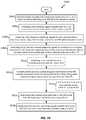
- FIG. 20is described below in conjunction with a flow chart illustrated in FIG. 21 . That is, FIG. 21 is a flow chart illustrating an exemplary process 2100 for resource assignment and re-assignment utilizing a paired set of primary and secondary TDD carriers in accordance with some aspects of the present disclosure.
- the process 2100is described from the point-of-view of a scheduling entity 1901 , and may accordingly, as described in conjunction with FIG. 20 , be operational at the scheduling entity 102 described above in conjunction with FIGS. 1 and/or 2 .
- the process 2100may be operational by a general purpose processor, a processing system 214 as described above and illustrated in FIG. 2 , or any suitable means for carrying out the described functions.
- the specific order of steps or blocks shown in FIG. 21is merely exemplary in nature, and in various aspects of the disclosure, these steps or blocks may occur in any suitable order, with some examples including two or more steps or blocks occurring simultaneously.
- the blocks 2102 and 2104may repeat, or be iterated a plurality of times in various examples, as regular uplink data 1922 may continue to be transmitted from the subordinate entities. However, at any given time, it may arise that the scheduling entity 1901 may wish to transmit LoLat data to a particular subordinate entity (i.e., the LoLat user 1904 ). Accordingly, at block 2106 , the scheduling entity 1901 may transmit an assignment or grant 1912 of time-frequency resources on the LoLat grant channel 1910 on the secondary TDD component carrier, to at least one subordinate entity (e.g., the LoLat user 1904 ).
- the resource assignment 1912may indicate for the LoLat user 1904 to receive LoLat downlink data from the scheduling entity 1901 utilizing at least one short TTI.
- the resource assignment 1912may include information identifying a particular subordinate entity 1904 , and information identifying time-frequency resources granted on the primary TDD component carrier for the LoLat downlink transmission.
- the scheduling entity 1901may optionally (as indicated by the dashed-line box 2108 ) transmit an uplink scheduling grant modification 1924 on any suitable channel, e.g., on the secondary TDD component carrier.
- the uplink scheduling grant modification 1924may instruct the regular users such as the first subordinate entity 1902 , having granted time-frequency resources for long-TTI uplink transmissions, to puncture their uplink transmissions during at least one designated short TTI (i.e., the short TTI(s) corresponding to the LoLat grant 1912 ).
- a thin LoLat grant channel 1912can enable a scheduling entity to rapidly and dynamically control the multiplexing of uplink and downlink data on the primary TDD component carrier having at least two different data types or categories, from a set of subordinate entities.
- TDD-TDD Carrier PairingMultiplexing LoLat UL on Regular DL
- FIG. 22illustrates yet another example of pairing primary and secondary TDD component carriers, providing for multiplexing of LoLat uplink transmissions (i.e., transmissions from a subordinate entity) with regular downlink transmissions (i.e., transmissions from a scheduling entity).
- the primary TDD component carrieris illustrated in much the same way as the TDD carrier in FIG. 8 , with downlink resources shown with a scheduling entity transmitting regular downlink data utilizing a long TTI to plurality of users (subordinate entities).
- the scheduling entitymay modify the scheduling assignment or grant of time-frequency resources, interrupting the ongoing downlink transmissions on the primary TDD component carrier, to enable uplink transmissions (e.g., LoLat data transmissions) on the primary TDD component carrier.
- uplink transmissionse.g., LoLat data transmissions
- control channels for controlling the data carried on the primary TDD component carriermay be carried on either or both of the primary and/or secondary TDD component carriers.
- the primary TDD component carrierincludes a LoLat grant channel 2212 in which a subordinate entity may receive information such as a LoLat uplink grant 2214 , which may carry grant information for the LoLat user 2204 that requested LoLat scheduling to utilize for transmitting a LoLat uplink transmission.
- the primary TDD component carrierfurther includes a thin control channel 2216 that may carry a downlink grant modification 2218 , which modifies a downlink time-frequency resource grant corresponding to the regular users' 2202 downlink data reception on the primary TDD component carrier.
- time-frequency resources corresponding to the long TTImay be granted for downlink transmissions on the primary TDD component carrier to one or more subordinate entities (e.g., Users A-F) by utilizing any suitable downlink grant channel (not necessarily one of the illustrated channels).
- subordinate entitiese.g., Users A-F
- any suitable downlink grant channelnot necessarily one of the illustrated channels.
- this subordinate entitymay transmit a LoLat scheduling request 2210 on the thin feedback channel 2208 on the secondary TDD component carrier.
- the LoLat scheduling request 2210may utilize the short TTI, although this is not necessarily always the case.
- the data carrieris a TDD carrier
- the downlink data transmissions to the regular users 2202 utilizing the long TTIare punctured, ceased, or suspended.
- the LoLat user 2204may transmit its LoLat uplink transmission on the primary TDD component carrier, resulting in an orthogonal multiple access scheme between regular downlink transmissions and LoLat uplink transmissions on the primary TDD component carrier.
- the scheduling entitymay suspend its regular downlink data transmissions on the primary TDD component carrier. That is, a gap or guard time 2206 may optionally be utilized when multiplexing LoLat uplink transmissions and regular downlink transmissions on the primary TDD component carrier.
- this guard time 2206may for example compensate for any propagation delay or other air interface delay, allowing full completion of the regular downlink transmissions to all users in the service area prior to the time when the LoLat uplink transmissions commence on the primary TDD component carrier.
- FIG. 23is a call flow diagram illustrating an exemplary resource assignment and re-assignment procedure as it might occur in accordance with one example for multiplexing uplink and downlink data with different latency targets utilizing a paired set of primary and secondary TDD component carriers.
- timemoves forward in the downward direction, and communication signals between the illustrated entities are denoted with arrows between the lines below the respective entities.
- a scheduling entity 2201is in communication with a plurality of subordinate entities 104 , including a regular user 2202 and a LoLat user 2204 .
- Each entity 2201 , 2202 , and 2204is configured for communication over primary and secondary TDD component carriers.
- the respective primary and secondary TDD component carriersare illustrated schematically with the two vertical lines extending down from each respective entity.
- the scheduling entity 2201may transmit a first assignment or grant 2220 of time-frequency resources to at least one subordinate entity on the secondary TDD component carrier.
- Any suitable control channel on the secondary TDD component carrier(or, in some examples, on the primary TDD component carrier) may be utilized for the first resource assignment 2220 , such as a downlink assignment channel.
- the first resource assignment 2220may be configured to indicate which time-frequency resource or resources are assigned to the respective subordinate entities for receiving regular transmissions of downlink data, that is, transmissions utilizing the long TTI.
- the scheduling entity 2201may transmit regular downlink data 2222 on the primary TDD component carrier to the at least one subordinate entity (e.g., the subordinate entities 2202 and 2204 ) utilizing the long TTI.
- this regular uplink data 2222may correspond to the downlink transmissions to regular users 2202 .
- regular downlink data 2222may optionally be transmitted to the second subordinate entity 2204 , depending on the contents of the first resource assignment 2220 and whether the second subordinate entity 2204 is configured to receive downlink data transmissions utilizing the long TTI.
- the blocks 2402 and 2404may repeat, or be iterated a plurality of times in various examples, as regular downlink data 2222 may continue to be transmitted to the subordinate entities. However, at any given time, it may arise that the subordinate entity 2204 (i.e., the LoLat user 2204 ) may wish to transmit LoLat uplink data to the scheduling entity 2201 . Accordingly, at block 2406 , the scheduling entity 2201 may receive a LoLat scheduling request 2210 on the thin feedback channel 2208 on the secondary TDD component carrier from the LoLat user 2204 (i.e., the second subordinate entity 2204 ).
- the LoLat scheduling request 2210may include information identifying the requesting subordinate entity 2204 , and including any pertinent information relating to the LoLat data desired to be transmitted.
- the scheduling entity 2201may transmit a second assignment or grant 2214 of time-frequency resources on a LoLat grant channel 2212 on the primary TDD component carrier, to the requesting subordinate entity 2204 .
- the second resource assignment 2214may include information identifying the requesting subordinate entity 2204 , and information identifying time-frequency resources granted on the TDD uplink carrier for the LoLat uplink transmission.
- the scheduling entity 2201may transmit a downlink scheduling grant modification 2218 on the thin control channel 2216 on the primary TDD component carrier.
- the downlink scheduling grant modification 2218may instruct the regular users such as the first subordinate entity 2202 , having granted time-frequency resources for long-TTI downlink transmissions, to ignore any uplink transmissions during at least one designated short TTI. That is, since the transmissions during that TTI will be LoLat uplink transmissions 2224 from the LoLat user 2204 , not directed to the regular user 2202 , the data may not be decodable by the regular user 2202 and can be ignored by the regular user 2202 during post-processing of the corresponding long TTI.
- the transmission of the downlink scheduling grant modification 2218 at block 2412 , and the transmission of the LoLat uplink data 2224 on the primary TDD component carrier at block 2414 (and the corresponding suspension of downlink data transmissions on the primary TDD component carrier, not including any guard time that may be added),may occur simultaneously. While this may violate orthogonality, the regular users may be suitably configured to ignore the information corresponding to the time-frequency resources allocated to the LoLat user 2204 during post-processing, as indicated in the downlink grant modification 2218 . In other examples, these transmissions may be at different times, according to the details of a particular implementation.
- the regular users 2202may be configured to buffer or cache the contents of the thin control channel 2216 and the primary TDD component carrier, such that the ignoring of data during the designated short TTI(s) may be performed during post-processing by the regular users 2202 .
- the scheduling entity 2201may receive the LoLat uplink data 2224 transmitted from the requesting subordinate entity 2204 utilizing the short TTI on the primary TDD component carrier.
- the scheduling entity 2201may resume transmitting the regular downlink data 2222 on the primary TDD component carrier, to one or more subordinate entities, such as the regular user 2202 utilizing the long TTI.
- a thin control channel 2216 and thin feedback channel 2208can enable a scheduling entity to multiplex uplink and downlink data having at least two different data types or categories, for set of subordinate entities.
- a flow chartis provided illustrating an exemplary process 2500 of wireless communication utilizing a TDD carrier paired with a second carrier, and multiplexing long and short TTIs, according to some aspects of the disclosure.
- the process 2500may be implemented by the scheduling entity 102 illustrated in FIGS. 1 and 2 ; the scheduling entities 501 , 801 , 1101 , 1601 , 1901 , or 2201 illustrated in FIGS. 5, 8, 11, 16, 19, and 22 , respectively; by a processing system 214 including a processor 204 ; or by any suitable means for carrying out the described functions.
- FIG. 26flow chart is provided illustrating an exemplary process 2600 of wireless communication utilizing a pair of TDD carriers for full duplex communication, according to some aspects of the disclosure.
- the process 2600may be implemented by the scheduling entity 102 illustrated in FIGS. 1 and 2 ; the scheduling entities 501 , 801 , 1101 , 1601 , 1901 , or 2201 illustrated in FIGS. 5, 8, 11, 16, 19, and 22 , respectively; by a processing system 214 including a processor 204 ; or by any suitable means for carrying out the described functions.
- a scheduling entity 102may wirelessly communicate over a first TDD carrier.
- wirelessly communicatingmay include transmitting and/or receiving data and/or control information on one or more communication channels, as described above.
- the scheduling entity 102may wirelessly communicate over a second TDD carrier paired with the first TDD carrier, but separated from the first TDD carrier in frequency.
- at least a portion of time slots in the first TDD carriermay be complementary in direction to a direction of time-aligned time slots in the second TDD carrier. That is, at least one uplink time slot in the first TDD carrier may be time-aligned with a downlink time slot in the second TDD carrier.
- the word “exemplary”is used to mean “serving as an example, instance, or illustration.” Any implementation or aspect described herein as “exemplary” is not necessarily to be construed as preferred or advantageous over other aspects of the disclosure. Likewise, the term “aspects” does not require that all aspects of the disclosure include the discussed feature, advantage or mode of operation.
- the term “coupled”is used herein to refer to the direct or indirect coupling between two objects. For example, if object A physically touches object B, and object B touches object C, then objects A and C may still be considered coupled to one another—even if they do not directly physically touch each other. For instance, a first die may be coupled to a second die in a package even though the first die is never directly physically in contact with the second die.
Landscapes
- Engineering & Computer Science (AREA)
- Signal Processing (AREA)
- Computer Networks & Wireless Communication (AREA)
- Mobile Radio Communication Systems (AREA)
- Time-Division Multiplex Systems (AREA)
- Transceivers (AREA)
Abstract
Description
Claims (92)
Priority Applications (29)
| Application Number | Priority Date | Filing Date | Title |
|---|---|---|---|
| US14/567,985US11153875B2 (en) | 2014-05-19 | 2014-12-11 | Apparatus and method for inter-band pairing of carriers for time division duplex transmit- and receive-switching and its application to multiplexing of different transmission time intervals |
| EP15723633.2AEP3146784B1 (en) | 2014-05-19 | 2015-05-08 | Apparatus and method for inter-band pairing of carriers for time division duplex transmit- and receive-switching and its application to multiplexing of different transmission time intervals |
| RU2016145059ARU2693295C2 (en) | 2014-05-19 | 2015-05-08 | Device and method for interband banding of carriers for switching transmission and reception of duplex with time division of channels and their application to multiplexing of different transmission time intervals |
| PT157236332TPT3146784T (en) | 2014-05-19 | 2015-05-08 | Apparatus and method for inter-band pairing of carriers for time division duplex transmit- and receive-switching and its application to multiplexing of different transmission time intervals |
| KR1020217033058AKR102433716B1 (en) | 2014-05-19 | 2015-05-08 | Apparatus and method for inter-band pairing of carriers for time division duplex transmit- and receive-switching and its application to multiplexing of different transmission time intervals |
| ES15723633TES2831413T3 (en) | 2014-05-19 | 2015-05-08 | Apparatus and procedure for pairing between carrier bands for switching transmission and reception of time division duplexing and its application to the multiplexing of different transmission time intervals |
| PH1/2016/502225APH12016502225B1 (en) | 2014-05-19 | 2015-05-08 | Apparatus and method for inter-band pairing of carriers for time division duplex transmit-and receive-switching and its application to multiplexing of different transmission time intervals |
| CA2946897ACA2946897C (en) | 2014-05-19 | 2015-05-08 | Apparatus and method for inter-band pairing of carriers for time division duplex transmit- and receive-switching and its application to multiplexing of different transmission time intervals |
| CN201911233825.7ACN110913489B (en) | 2014-05-19 | 2015-05-08 | Apparatus and method for inter-band pairing of time division duplex transmit and receive switched carriers |
| MX2016014269AMX372788B (en) | 2014-05-19 | 2015-05-08 | APPARATUS AND METHOD FOR INTER-BAND CARRIER MATCHING FOR TIME DIVISION DUPLEXING TRANSMISSION AND RECEPTION SWITCHING AND ITS APPLICATION FOR MULTIPLEXING DIFFERENT TRANSMISSION TIME INTERVALS. |
| AU2015264614AAU2015264614B9 (en) | 2014-05-19 | 2015-05-08 | Apparatus and method for inter-band pairing of carriers for time division duplex transmit- and receive-switching and its application to multiplexing of different transmission time intervals |
| CN201580025518.3ACN106464472B (en) | 2014-05-19 | 2015-05-08 | Apparatus and method for inter-band pairing of carriers for time division duplex transmission and reception switching and their application for multiplexing of different transmission time intervals |
| MYPI2016703781AMY188551A (en) | 2014-05-19 | 2015-05-08 | Apparatus and method for inter-band pairing of carriers for time division duplex transmit- and receive-switching and its application to multiplexing of different transmission time intervals |
| CA3167724ACA3167724C (en) | 2014-05-19 | 2015-05-08 | Apparatus and method for inter-band pairing of carriers for time division duplex transmit-and receive-switching and its application to multiplexing of different transmission time intervals |
| HUE15723633AHUE050679T2 (en) | 2014-05-19 | 2015-05-08 | Apparatus and method for inter-band pairing of carriers for time division duplex transmit- and receive-switching and its application to multiplexing of different transmission time intervals |
| NZ725378ANZ725378B2 (en) | 2014-05-19 | 2015-05-08 | Apparatus and method for inter-band pairing of carriers for time division duplex transmit- and receive-switching and its application to multiplexing of different transmission time intervals |
| SG11201608352YASG11201608352YA (en) | 2014-05-19 | 2015-05-08 | Apparatus and method for inter-band pairing of carriers for time division duplex transmit- and receive-switching and its application to multiplexing of different transmission time intervals |
| PCT/US2015/029964WO2015179145A1 (en) | 2014-05-19 | 2015-05-08 | Apparatus and method for inter-band pairing of carriers for time division duplex transmit- and receive-switching and its application to multiplexing of different transmission time intervals |
| SI201531411TSI3146784T1 (en) | 2014-05-19 | 2015-05-08 | Apparatus and method for inter-band pairing of carriers for time division duplex transmit- and receive-switching and its application to multiplexing of different transmission time intervals |
| DK15723633.2TDK3146784T3 (en) | 2014-05-19 | 2015-05-08 | APPARATUS AND METHOD FOR INTER-TAPE MATCHING CARRIERS FOR TIME DIVISION DUPLEX SENDING AND RECEIVING SWITCHING AND ITS APPLICATION FOR MULTIPLEXING OF DIFFERENT TRANSMISSION TIME INTERVALS |
| JP2016567997AJP6640744B2 (en) | 2014-05-19 | 2015-05-08 | Apparatus and method for interband pairing of carriers for time division duplex transmission and reception switching and its application to multiplexing of different transmission time intervals |
| KR1020167032473AKR102433714B1 (en) | 2014-05-19 | 2015-05-08 | Apparatus and method for inter-band pairing of carriers for time division duplex transmit- and receive-switching and its application to multiplexing of different transmission time intervals |
| TW104114929ATWI713347B (en) | 2014-05-19 | 2015-05-11 | Apparatus and method for inter-band pairing of carriers for time division duplex transmit- and receive-switching and its application to multiplexing of different transmission time intervals |
| IL248832AIL248832A0 (en) | 2014-05-19 | 2016-11-08 | Apparatus and method for inter-band pairing of carriers for time division duplex transmit- and receive-switching and its application to multiplexing of different transmission time intervals |
| SA516380311ASA516380311B1 (en) | 2014-05-19 | 2016-11-15 | Wireless Communication Apparatus and Method Operable at a Scheduling Entity |
| CL2016002930ACL2016002930A1 (en) | 2014-05-19 | 2016-11-17 | Apparatus and method for inter-band carrier pairing for transmission switching and reception of time division duplexing and its application to multiplex different transmission time intervals |
| ZA2016/07998AZA201607998B (en) | 2014-05-19 | 2016-11-18 | Apparatus and method for inter-band pairing of carriers for time division duplex transmit- and receive-switching and its application to multiplexing of different transmission time intervals |
| US17/321,223US11832230B2 (en) | 2014-05-19 | 2021-05-14 | Apparatus and method for inter-band pairing of carriers for time division duplex transmit- and receive-switching and its application to multiplexing of different transmission time |
| US18/482,809US20240040555A1 (en) | 2014-05-19 | 2023-10-06 | Apparatus and method for inter-band pairing of carriers for time division duplex transmit- and receive-switching and its application to multiplexing of different transmission time intervals |
Applications Claiming Priority (3)
| Application Number | Priority Date | Filing Date | Title |
|---|---|---|---|
| US201462000443P | 2014-05-19 | 2014-05-19 | |
| US201462000454P | 2014-05-19 | 2014-05-19 | |
| US14/567,985US11153875B2 (en) | 2014-05-19 | 2014-12-11 | Apparatus and method for inter-band pairing of carriers for time division duplex transmit- and receive-switching and its application to multiplexing of different transmission time intervals |
Related Child Applications (1)
| Application Number | Title | Priority Date | Filing Date |
|---|---|---|---|
| US17/321,223ContinuationUS11832230B2 (en) | 2014-05-19 | 2021-05-14 | Apparatus and method for inter-band pairing of carriers for time division duplex transmit- and receive-switching and its application to multiplexing of different transmission time |
Publications (2)
| Publication Number | Publication Date |
|---|---|
| US20150334686A1 US20150334686A1 (en) | 2015-11-19 |
| US11153875B2true US11153875B2 (en) | 2021-10-19 |
Family
ID=54539403
Family Applications (5)
| Application Number | Title | Priority Date | Filing Date |
|---|---|---|---|
| US14/567,985Active2038-10-21US11153875B2 (en) | 2014-05-19 | 2014-12-11 | Apparatus and method for inter-band pairing of carriers for time division duplex transmit- and receive-switching and its application to multiplexing of different transmission time intervals |
| US14/567,993Active2039-03-22US11019620B2 (en) | 2014-05-19 | 2014-12-11 | Apparatus and method for inter-band pairing of carriers for time division duplex transmit- and receive-switching and its application to multiplexing of different transmission time intervals |
| US14/567,979Active2036-06-03US10278178B2 (en) | 2014-05-19 | 2014-12-11 | Apparatus and method for inter-band pairing of carriers for time division duplex transmit- and receive-switching |
| US17/321,223Active2035-06-01US11832230B2 (en) | 2014-05-19 | 2021-05-14 | Apparatus and method for inter-band pairing of carriers for time division duplex transmit- and receive-switching and its application to multiplexing of different transmission time |
| US18/482,809PendingUS20240040555A1 (en) | 2014-05-19 | 2023-10-06 | Apparatus and method for inter-band pairing of carriers for time division duplex transmit- and receive-switching and its application to multiplexing of different transmission time intervals |
Family Applications After (4)
| Application Number | Title | Priority Date | Filing Date |
|---|---|---|---|
| US14/567,993Active2039-03-22US11019620B2 (en) | 2014-05-19 | 2014-12-11 | Apparatus and method for inter-band pairing of carriers for time division duplex transmit- and receive-switching and its application to multiplexing of different transmission time intervals |
| US14/567,979Active2036-06-03US10278178B2 (en) | 2014-05-19 | 2014-12-11 | Apparatus and method for inter-band pairing of carriers for time division duplex transmit- and receive-switching |
| US17/321,223Active2035-06-01US11832230B2 (en) | 2014-05-19 | 2021-05-14 | Apparatus and method for inter-band pairing of carriers for time division duplex transmit- and receive-switching and its application to multiplexing of different transmission time |
| US18/482,809PendingUS20240040555A1 (en) | 2014-05-19 | 2023-10-06 | Apparatus and method for inter-band pairing of carriers for time division duplex transmit- and receive-switching and its application to multiplexing of different transmission time intervals |
Country Status (23)
| Country | Link |
|---|---|
| US (5) | US11153875B2 (en) |
| EP (4) | EP3419367B1 (en) |
| JP (3) | JP6640745B2 (en) |
| KR (4) | KR102433714B1 (en) |
| CN (5) | CN106464472B (en) |
| AU (2) | AU2015264614B9 (en) |
| CA (3) | CA3167724C (en) |
| CL (2) | CL2016002931A1 (en) |
| DK (1) | DK3146784T3 (en) |
| ES (2) | ES2831413T3 (en) |
| HU (1) | HUE050679T2 (en) |
| IL (2) | IL248832A0 (en) |
| MX (2) | MX372788B (en) |
| MY (1) | MY188551A (en) |
| PH (2) | PH12016502225B1 (en) |
| PT (1) | PT3146784T (en) |
| RU (2) | RU2693295C2 (en) |
| SA (2) | SA516380305B1 (en) |
| SG (2) | SG11201608350WA (en) |
| SI (1) | SI3146784T1 (en) |
| TW (3) | TWI713347B (en) |
| WO (3) | WO2015179144A1 (en) |
| ZA (2) | ZA201607998B (en) |
Cited By (1)
| Publication number | Priority date | Publication date | Assignee | Title |
|---|---|---|---|---|
| US12047993B2 (en) | 2014-05-19 | 2024-07-23 | Qualcomm Incorporated | Apparatus and method for synchronous multiplexing and multiple access for different latency targets utilizing thin control |
Families Citing this family (85)
| Publication number | Priority date | Publication date | Assignee | Title |
|---|---|---|---|---|
| US11153875B2 (en) | 2014-05-19 | 2021-10-19 | Qualcomm Incorporated | Apparatus and method for inter-band pairing of carriers for time division duplex transmit- and receive-switching and its application to multiplexing of different transmission time intervals |
| US9775151B2 (en)* | 2014-07-21 | 2017-09-26 | Intel IP Corporation | System and method for TDD communications |
| US11324022B1 (en) | 2014-10-06 | 2022-05-03 | Sprint Spectrum L.P. | Method and system for selecting a carrier on which to schedule communications of a type of bearer traffic |
| US10560245B2 (en)* | 2014-10-21 | 2020-02-11 | Lg Electronics Inc. | Data transmission/reception method in wireless communication system that supports low latency, and apparatus therefor |
| US9807766B1 (en)* | 2015-01-30 | 2017-10-31 | Sprint Spectrum L.P. | Method and system for component carrier selection based on content type |
| WO2016126108A1 (en)* | 2015-02-03 | 2016-08-11 | Lg Electronics Inc. | Method and apparatus for performing synchronization for carrier without synchronization signal in wireless communication system |
| US9629066B2 (en)* | 2015-02-24 | 2017-04-18 | Huawei Technologies Co., Ltd. | System and method for transmission time intervals |
| JP6662371B2 (en)* | 2015-03-06 | 2020-03-11 | 日本電気株式会社 | Radio station, radio terminal device, and methods thereof |
| JP6658729B2 (en) | 2015-03-06 | 2020-03-04 | 日本電気株式会社 | Radio station, radio terminal device, and methods thereof |
| US9936519B2 (en) | 2015-03-15 | 2018-04-03 | Qualcomm Incorporated | Self-contained time division duplex (TDD) subframe structure for wireless communications |
| US10342012B2 (en) | 2015-03-15 | 2019-07-02 | Qualcomm Incorporated | Self-contained time division duplex (TDD) subframe structure |
| US10075970B2 (en)* | 2015-03-15 | 2018-09-11 | Qualcomm Incorporated | Mission critical data support in self-contained time division duplex (TDD) subframe structure |
| US9800392B1 (en)* | 2015-04-16 | 2017-10-24 | Sprint Spectrum L.P. | Selecting between TDD-FDD carrier aggregation approaches based on type of communication |
| US9992790B2 (en) | 2015-07-20 | 2018-06-05 | Qualcomm Incorporated | Time division duplex (TDD) subframe structure supporting single and multiple interlace modes |
| WO2017023352A1 (en)* | 2015-08-06 | 2017-02-09 | Intel IP Corporation | Performing mission critical communications at a user equipment (ue) |
| WO2017099369A1 (en) | 2015-12-06 | 2017-06-15 | 엘지전자 주식회사 | Method and apparatus for communication using multiple tti structures |
| WO2017113206A1 (en) | 2015-12-30 | 2017-07-06 | 华为技术有限公司 | Data communication method, terminal device, and network device |
| WO2017117744A1 (en) | 2016-01-06 | 2017-07-13 | 广东欧珀移动通信有限公司 | Method for transmitting information and device |
| CN106982456B (en)* | 2016-01-15 | 2021-12-31 | 华为技术有限公司 | Communication transmission method, terminal equipment and base station |
| CN108476429B (en)* | 2016-01-18 | 2023-03-21 | 联想创新有限公司(香港) | UCI transmission using different subframe types |
| EP3295753B1 (en)* | 2016-01-21 | 2019-01-02 | Telefonaktiebolaget LM Ericsson (publ) | Systems and methods for multiplexing scheduling requests in unlicensed bands |
| WO2017130991A1 (en)* | 2016-01-27 | 2017-08-03 | 株式会社Nttドコモ | User terminal, wireless base station, and wireless communication method |
| US10165564B2 (en) | 2016-01-28 | 2018-12-25 | Sharp Kabushiki Kaisha | Systems and methods for association timing |
| JP2019054314A (en)* | 2016-02-02 | 2019-04-04 | シャープ株式会社 | Terminal apparatus and method |
| US10517104B2 (en)* | 2016-02-02 | 2019-12-24 | Qualcomm Incorporated | Interference management for networks with variable transmission time intervals |
| CN107040347B (en)* | 2016-02-03 | 2021-05-25 | 电信科学技术研究院 | Uplink transmission method and device |
| WO2017134336A1 (en)* | 2016-02-04 | 2017-08-10 | Nokia Technologies Oy | Short transmission time interval backwards compatible arrangement |
| EP3437408A1 (en)* | 2016-03-30 | 2019-02-06 | Interdigital Patent Holdings, Inc. | Method and procedures for downlink physical channels to reduce latency in an lte advanced system |
| EP3796589B1 (en)* | 2016-03-30 | 2023-04-26 | Huawei Technologies Co., Ltd. | Information processing method, terminal device, network device, and communications system |
| BR112018067470A2 (en)* | 2016-03-31 | 2019-01-02 | Sony Corp | terminal device, base station device, and method of communication. |
| WO2017166191A1 (en)* | 2016-03-31 | 2017-10-05 | 华为技术有限公司 | Signal processing method and network device |
| EP3437410A4 (en)* | 2016-04-01 | 2019-10-23 | Telefonaktiebolaget LM Ericsson (publ) | Collision handling between legacy tti and short tti |
| US10420079B2 (en)* | 2016-04-01 | 2019-09-17 | Hfi Innovation Inc. | Efficient control and data multiplexing in communication systems |
| US10728893B2 (en)* | 2016-04-04 | 2020-07-28 | Qualcomm Incorporated | Time-division multiplexing transmission time intervals within a subframe or slot for MMW scheduling |
| WO2017183912A1 (en)* | 2016-04-19 | 2017-10-26 | Lg Electronics Inc. | Ways for supporting multiple ttis |
| US11690051B2 (en)* | 2016-04-29 | 2023-06-27 | Lg Electronics Inc. | Method and apparatus for configuring frame structure for new radio access technology in wireless communication system |
| AU2016406271A1 (en) | 2016-05-12 | 2018-12-06 | Huawei Technologies Co., Ltd. | Resource indication method, related apparatus, and system |
| WO2017193351A1 (en)* | 2016-05-12 | 2017-11-16 | 华为技术有限公司 | Signal transmission method and terminal |
| US10827384B2 (en) | 2016-05-13 | 2020-11-03 | Telefonaktiebolaget L M Ericsson (Publ) | Subframe selection for introducing short TTIs in TDD |
| JP6722301B2 (en)* | 2016-05-13 | 2020-07-15 | テレフオンアクチーボラゲット エルエム エリクソン(パブル) | Setting Up Uplink Transmission for Wireless Devices |
| EP3471361B1 (en) | 2016-06-17 | 2021-10-06 | LG Electronics Inc. | Method and user equipment for receiving downlink signal, method and base station for transmitting downlink signal |
| US10912149B2 (en)* | 2016-07-22 | 2021-02-02 | Hitachi Kokusai Electric Inc. | Communication device |
| US10419264B2 (en) | 2016-07-27 | 2019-09-17 | Qualcomm Incorporated | Subframe structure for the co-existence network of sidelink and mission critical mobile devices |
| TWI663863B (en)* | 2016-08-10 | 2019-06-21 | 諾基亞科技公司 | Signaling for uplink short transmission time interval transmissions and associated method, apparatus, computer program product and computer readable medium |
| WO2018030710A1 (en)* | 2016-08-11 | 2018-02-15 | Samsung Electronics Co., Ltd. | Method and apparatus for scheduling uplink data in mobile communication system |
| US10939361B2 (en) | 2016-08-12 | 2021-03-02 | Huawei Technologies Co., Ltd. | Control information sending method, control information receiving method, and device |
| US11051208B2 (en)* | 2016-08-25 | 2021-06-29 | Huawei Technologies Co., Ltd. | Co-existence of low latency and latency tolerant downlink communication |
| US11071136B2 (en) | 2016-08-25 | 2021-07-20 | Huawei Technologies Co., Ltd. | System and method for multiplexing traffic |
| US11252717B2 (en) | 2016-09-02 | 2022-02-15 | Huawei Technologies Co., Ltd. | Co-existence of latency tolerant and low latency communications |
| US10687252B2 (en)* | 2016-09-28 | 2020-06-16 | Qualcomm Incorporated | Bandwidth group (BWG) for enhanced channel and interference mitigation in 5G new radio |
| US10484972B2 (en)* | 2016-10-21 | 2019-11-19 | Qualcomm Incorporated | Puncture recovery and resource reclaiming for multi-priority scheduling |
| US10743332B2 (en)* | 2016-11-18 | 2020-08-11 | Qualcomm Incorporated | Techniques and apparatuses for complementary transmission relating to an interrupted traffic flow in new radio |
| WO2018098623A1 (en) | 2016-11-29 | 2018-06-07 | 北京小米移动软件有限公司 | Transmission time interval determination method and device, base station, and user equipment |
| EP3571882A4 (en)* | 2017-01-18 | 2020-08-05 | Nokia Technologies Oy | Resource allocations |
| WO2018143398A1 (en)* | 2017-02-02 | 2018-08-09 | 株式会社Nttドコモ | User terminal and wireless communication method |
| EP3720227B1 (en)* | 2017-02-03 | 2022-11-23 | Telefonaktiebolaget LM Ericsson (publ) | Methods and apparatus for utilizing short transmission time intervals in a wireless communications network |
| GB2559383B (en) | 2017-02-03 | 2021-09-22 | Vodafone Ip Licensing Ltd | Transmission time frame structure for time division duplex communication |
| EP3577987B1 (en)* | 2017-02-06 | 2023-07-05 | Telefonaktiebolaget LM Ericsson (publ) | Uplink puncturing of mini-slot on slot transmissions |
| EP3603256B1 (en)* | 2017-03-21 | 2020-05-13 | Telefonaktiebolaget LM Ericsson (publ) | Network node and method in a wireless communications network |
| KR102409062B1 (en) | 2017-03-23 | 2022-06-15 | 삼성전자 주식회사 | Apparatus and method for transmitting and receiving of data in a wireless communication system |
| CN108631912B (en)* | 2017-03-23 | 2021-09-28 | 大唐移动通信设备有限公司 | Transmission method and device |
| US11595970B2 (en)* | 2017-03-24 | 2023-02-28 | Qualcomm Incorporated | UE-specific slot structure configuration |
| WO2018176499A1 (en)* | 2017-04-01 | 2018-10-04 | 深圳前海达闼云端智能科技有限公司 | Subframe time sequence configuration method and apparatus, network side device, and terminal side device |
| US10548165B2 (en)* | 2017-04-25 | 2020-01-28 | Qualcomm Incorporated | Flexible scheduling in new radio (NR) networks |
| US11497007B2 (en) | 2017-05-05 | 2022-11-08 | Qualcomm Incorporated | Sounding reference signal configuration and transport block size scaling in low latency systems |
| CN109391442B (en)* | 2017-08-11 | 2020-12-08 | 电信科学技术研究院 | Data transmission method and device |
| EP3444987A1 (en) | 2017-08-17 | 2019-02-20 | Fraunhofer-Gesellschaft zur Förderung der angewandten Forschung e.V. | Punctured/on-demand control information for flexible/full duplex communication |
| US10869322B2 (en)* | 2017-09-07 | 2020-12-15 | Qualcomm Incorporated | Supporting low-latency traffic over a wireless mesh network |
| US11063733B2 (en)* | 2017-11-09 | 2021-07-13 | Qualcomm Incorporated | Duplexing modes based on power configurations for transmissions |
| US10708865B2 (en) | 2017-11-17 | 2020-07-07 | Qualcomm Incorporated | Techniques for power control using carrier aggregation in wireless communications |
| BR112020010500A2 (en) | 2017-11-27 | 2020-11-10 | Telefonaktiebolaget Lm Ericsson (Publ) | radio resource allocation method, radio device, first radio device, communication system, method implemented in a communication system, and, user equipment |
| CN110719642B (en)* | 2018-07-11 | 2023-01-13 | 华为技术有限公司 | Method and device for data transmission |
| US10887904B2 (en)* | 2018-08-10 | 2021-01-05 | Qualcomm Incorporated | Cross-carrier scheduling enhancements in new radio (NR) |
| US10951386B2 (en) | 2018-09-20 | 2021-03-16 | At&T Intellectual Property I, L.P. | Indication of interoperability and deployment tested time-division duplex slot formats |
| US11039399B2 (en) | 2019-02-05 | 2021-06-15 | Qualcomm Incorporated | Open loop power control for two-step random access |
| CN109995500B (en)* | 2019-03-08 | 2021-10-29 | 北京集创北方科技股份有限公司 | Data transmission method and display control device |
| US12200314B2 (en) | 2019-07-19 | 2025-01-14 | Mo-Dv, Inc. | Network arrangement using SNDS and SLANS |
| US12047659B2 (en)* | 2019-07-19 | 2024-07-23 | Mo-Dv, Inc. | Special network device |
| US11888787B2 (en)* | 2019-11-22 | 2024-01-30 | Huawei Technologies Co., Ltd. | Frame structures for wireless communication |
| US20210216060A1 (en)* | 2020-01-09 | 2021-07-15 | Myomega Systems Gmbh | Management of a reliable industrial control system via dedicated cellular network |
| US20210298026A1 (en)* | 2020-03-19 | 2021-09-23 | Qualcomm Incorporated | Uplink indication for full-duplex operation |
| WO2022027591A1 (en)* | 2020-08-07 | 2022-02-10 | Qualcomm Incorporated | Gap configuration in wireless communications |
| BR112023020153A2 (en)* | 2021-03-30 | 2023-11-28 | Interdigital Patent Holdings Inc | METHODS FOR ENABLE CARRIER SWITCHING FOR UPLINK CONTROL INFORMATION |
| CN115623598A (en)* | 2021-07-14 | 2023-01-17 | 华为技术有限公司 | Signal transmission method and device |
| KR20230079733A (en) | 2021-11-29 | 2023-06-07 | 삼성전자주식회사 | Display controller and display device including the same |
Citations (169)
| Publication number | Priority date | Publication date | Assignee | Title |
|---|---|---|---|---|
| US6466557B1 (en) | 1997-07-14 | 2002-10-15 | Sanyo Electric Co., Ltd. | Transmission channel allocation method and allocation apparatus |
| US6587444B1 (en) | 1997-11-14 | 2003-07-01 | Ericsson Inc. | Fixed frequency-time division duplex in radio communications systems |
| CN1451250A (en) | 2000-03-23 | 2003-10-22 | 西门子移动通讯公司 | Handover Process in Wireless Communication System |
| US20050013263A1 (en) | 2003-01-04 | 2005-01-20 | Samsung Electronics Co., Ltd. | Apparatus and method for transmitting/receiving uplink data retransmission request in a CDMA communication system |
| US6859655B2 (en) | 2001-01-19 | 2005-02-22 | Raze Technologies, Inc. | TDD FDD air interface |
| WO2005088866A1 (en) | 2004-03-16 | 2005-09-22 | Nokia Corporation | A method, a device and a system for duplex communications |
| US20060072508A1 (en) | 2004-09-30 | 2006-04-06 | Jialin Zou | Utilization of overhead channel quality metrics in a cellular network |
| CN1921322A (en) | 2005-08-26 | 2007-02-28 | 上海原动力通信科技有限公司 | Interference-suppress method for time slot code division multiple access system |
| WO2007025160A2 (en) | 2005-08-24 | 2007-03-01 | Qualcomm Incorporated | Varied transmission time intervals for wireless communication system |
| WO2007025260A2 (en) | 2005-08-26 | 2007-03-01 | Texas Instruments Incorporated | Transient triggered protection of ic components |
| US20070171932A1 (en) | 2006-01-20 | 2007-07-26 | General Dynamics C4 Systems, Inc. | System and method for dynamic allocation and routing of resources |
| US20080009280A1 (en) | 2006-07-07 | 2008-01-10 | Kazumasa Ushiki | Mobile station apparatus, wireless base station apparatus, and wireless communication system |
| CN101141801A (en) | 2006-09-06 | 2008-03-12 | 华为技术有限公司 | Channel resource block mapping method and device |
| CN201094150Y (en) | 2006-10-03 | 2008-07-30 | 美商内数位科技公司 | Wireless sending / receiving unit for uplink emitting power control |
| WO2008098223A2 (en) | 2007-02-09 | 2008-08-14 | Qualcomm Incorporated | Flexible channel quality indicator reporting |
| CN101277167A (en) | 2006-03-20 | 2008-10-01 | 华为技术有限公司 | Feedback control method, device and transceiver in OFDM system |
| US20080310360A1 (en) | 2007-06-13 | 2008-12-18 | Samsung Electronics Co., Ltd. | Method and apparatus for transmitting and receiving channel quality indicator in communication system |
| US20090070650A1 (en) | 2007-09-11 | 2009-03-12 | Nextwave Broadband Inc. | Error correction for a persistent resource allocation |
| WO2009036086A1 (en) | 2007-09-10 | 2009-03-19 | Qualcomm Incorporated | Methods and apparatus for including communication mode information (tdd or fdd) in a transmission frame for system acquisition |
| US20090080386A1 (en) | 2007-09-21 | 2009-03-26 | Qualcomm Incorporated | Interference management employing fractional time reuse |
| WO2009063001A2 (en) | 2007-11-16 | 2009-05-22 | Telefonaktiebolaget Lm Ericsson (Publ) | Adaptive scheduling for half-duplex wireless terminals |
| CN101485216A (en) | 2006-05-12 | 2009-07-15 | 松下电器产业株式会社 | Reserve radio resource for user in mobile communication system |
| US20090180433A1 (en) | 2008-01-07 | 2009-07-16 | Lg Electronics Inc. | Method of controlling transmission power in a wireless communication system |
| US20090180408A1 (en)* | 2008-01-11 | 2009-07-16 | John Graybeal | Realizing fdd capability by leveraging existing tdd technology |
| US20090245155A1 (en) | 2008-03-28 | 2009-10-01 | Fujitsu Limited | Wireless communication system, wireless base station, user equipment, and multi service management equipment |
| US20090257388A1 (en) | 2008-04-07 | 2009-10-15 | Qualcomm Incorporated | Systems and methods to define control channels using reserved resource blocks |
| US20090323625A1 (en) | 2007-03-12 | 2009-12-31 | Electronics And Telecommunications Research Institute | Radio resource allocation and data transmission in packet based mobile communication system |
| US20100027491A1 (en) | 2008-07-29 | 2010-02-04 | Alvarion Ltd. | Uplink resource control |
| WO2010019523A1 (en) | 2008-08-11 | 2010-02-18 | Qualcomm Incorporated | Multi-carrier design for control and procedures comprising pairing of carriers |
| US20100039970A1 (en) | 2008-08-14 | 2010-02-18 | Aris Papasakellariou | Method and apparatus for supporting multiple reference signals in ofdma communication systems |
| WO2010019679A2 (en) | 2008-08-12 | 2010-02-18 | Qualcomm Incorporated | Multi-carrier grant design |
| WO2010057008A1 (en) | 2008-11-14 | 2010-05-20 | Dbsd Satellite Services G.P. | Asymmetric tdd in flexible use spectrum |
| US20100210279A1 (en) | 2004-08-13 | 2010-08-19 | Broadcom Corporation | Dynamic Reconfiguration of Communication Resources in a Multi-Transceiver Configuration |
| US20100214996A1 (en) | 2009-02-25 | 2010-08-26 | Qualcomm Incorporated | High-priority communications session within a wireless communications system |
| US20100254268A1 (en) | 2009-04-02 | 2010-10-07 | So Yeon Kim | Method and apparatus for monitoring control channel in multiple carrier system |
| CN101868028A (en) | 2009-04-14 | 2010-10-20 | 中国移动通信集团公司 | A method for sending an uplink signal, a mobile terminal, a base station, and a wireless communication system |
| WO2010124438A1 (en) | 2009-04-27 | 2010-11-04 | 华为技术有限公司 | Method and device for switching |
| CN101917773A (en) | 2004-09-16 | 2010-12-15 | 摩托罗拉公司 | Systems and methods for downlink signaling for high speed uplink packet access |
| US20110013581A1 (en) | 2008-03-14 | 2011-01-20 | Moon Il Lee | Method for Channel Allocating in Wireless Access System |
| KR20110013425A (en) | 2008-05-02 | 2011-02-09 | 가부시키가이샤 엔티티 도코모 | Base station apparatus, user apparatus and method in mobile communication system |
| US20110044391A1 (en) | 2009-08-24 | 2011-02-24 | Samsung Electronics Co., Ltd. | Method and apparatus for configuring control channel in ofdm system |
| US20110075624A1 (en) | 2009-09-28 | 2011-03-31 | Samsung Electronics Co., Ltd. | Extending physical downlink control channels |
| US20110085506A1 (en) | 2009-10-09 | 2011-04-14 | Samsung Electronics Co., Ltd. | Method and apparatus for transmitting and receiving multi-user control channels in a wireless communication system with multiple antennas |
| US20110164532A1 (en) | 2008-03-28 | 2011-07-07 | Ntt Docomo, Inc. | User apparatus, base station apparatus, and communication control method |
| US20110164536A1 (en) | 2010-01-05 | 2011-07-07 | Industrial Technology Research Institute. | Systems and methods for data relay transmission |
| US20110268075A1 (en) | 2009-01-13 | 2011-11-03 | Youn Hyoung Heo | Method and apparatus for transmitting uplink control information in multi-carrier wireless communication system |
| US20110274031A1 (en) | 2010-05-05 | 2011-11-10 | Qualcomm Incorporated | Expanded search space for r-pdcch in lte-a |
| US20110273996A1 (en) | 2009-01-14 | 2011-11-10 | So Yeon Kim | Wireless apparatus for a multi-carrier system |
| US20110286397A1 (en) | 2009-01-05 | 2011-11-24 | So Yeon Kim | Wireless device in multicarrier system |
| US20110292890A1 (en) | 2010-05-28 | 2011-12-01 | Kabushiki Kaisha Toshiba | Radio resource management in femtocells |
| CN102273250A (en) | 2008-11-06 | 2011-12-07 | Lg电子株式会社 | Method for monitoring downlink control channel in user equipments |
| US8077670B2 (en) | 2009-04-10 | 2011-12-13 | Jianke Fan | Random access channel response handling with aggregated component carriers |
| CN102300244A (en) | 2011-07-15 | 2011-12-28 | 中兴通讯股份有限公司 | Interference measuring reference information notifying method and interference measuring method and device |
| US20110317615A1 (en) | 2010-06-23 | 2011-12-29 | Futurewei Technologies, Inc. | System and Method for Adapting Code Rate |
| US20120004841A1 (en) | 2010-07-02 | 2012-01-05 | Ford Global Technologies, Llc | Multi-modal navigation system and method |
| US20120039283A1 (en) | 2010-08-16 | 2012-02-16 | Qualcomm Incorporated | Search space design for relay physical downlink control channel (r-pdcch) |
| US20120039179A1 (en) | 2009-03-03 | 2012-02-16 | Lg Electronics Inc. | Method and apparatus for supporting multiple carriers |
| US20120044841A1 (en)* | 2010-08-18 | 2012-02-23 | Qualcomm Incorporated | H-arq timing and backhaul subframe configuration for tdd relay in lte-a |
| US20120057500A1 (en) | 2009-05-13 | 2012-03-08 | Kyocera Corporation | Radio base station and communication control method |
| JP2012054711A (en) | 2010-08-31 | 2012-03-15 | Ntt Docomo Inc | Radio communication system, radio base station device and mobile terminal device |
| US20120063324A1 (en) | 2009-05-14 | 2012-03-15 | So Yeon Kim | Device and method for monitoring the control channel in a multicarrier system |
| US20120069826A1 (en) | 2009-06-09 | 2012-03-22 | Panasonic Corporation | Terminal device and signal multiplexing control method |
| WO2012044988A1 (en) | 2010-10-01 | 2012-04-05 | Interdigital Patent Holdings, Inc. | Systems and methods for uplink feedback for high-speed downlink packet access (hsdpa) |
| US20120099519A1 (en) | 2009-06-25 | 2012-04-26 | Hak Seong Kim | Method and device for signal transmission on a wireless communications system |
| US20120122465A1 (en) | 2009-08-31 | 2012-05-17 | Landstroem Sara | Methods and Arrangements for Allocating Scheduling Request Resources in a Wireless Communication System |
| CN102474298A (en) | 2009-06-30 | 2012-05-23 | 阿尔卡特朗讯公司 | Receiver and method for performing interference cancellation |
| US8208925B2 (en) | 2007-02-21 | 2012-06-26 | Qualcomm Incorporated | Method and apparatus for inter-system handover |
| CN102651675A (en) | 2012-03-26 | 2012-08-29 | 华为技术有限公司 | Method for determining service authorization information and user equipment |
| US20120230238A1 (en) | 2009-10-28 | 2012-09-13 | Lars Dalsgaard | Resource Setting Control for Transmission Using Contention Based Resources |
| US20120250642A1 (en) | 2011-04-01 | 2012-10-04 | Futurewei Technologies, Inc. | System and Method for Transmission and Reception of Control Channels |
| CN102792656A (en) | 2010-03-10 | 2012-11-21 | Lg电子株式会社 | Method and apparatus for transmitting uplink control information in a wireless communication system |
| WO2012161914A1 (en) | 2011-05-23 | 2012-11-29 | Qualcomm Incorporated | A channel state information feedback for carrier aggregation with flexible carrier configurations |
| US20120320846A1 (en) | 2011-06-15 | 2012-12-20 | Samsung Electronics Co., Ltd. | Extension of physical downlink control signaling in a communication system |
| US20120327916A1 (en) | 2010-03-11 | 2012-12-27 | Joon Kui Ahn | Method for transmitting uplink control information and user device |
| US20130003929A1 (en) | 2008-05-08 | 2013-01-03 | L-3 Communications Security And Detection Systems, Inc. | Adaptive scanning in an imaging system |
| US20130021587A1 (en) | 2009-06-30 | 2013-01-24 | Casio Computer Co., Ltd. | Light source unit utilizing laser for light source and projector |
| US20130021954A1 (en) | 2011-07-18 | 2013-01-24 | Qualcomm Incorporated | Enabling half-duplex operation |
| US20130030158A1 (en) | 2007-02-23 | 2013-01-31 | Yeda Research And Development Co. Ltd. | Antibodies and pharmaceutical compositions containing same useful for inhibiting activity of metalloproteins |
| CN102934504A (en) | 2010-04-05 | 2013-02-13 | 株式会社Ntt都科摩 | Wireless communication control device and wireless communication control method |
| US20130039291A1 (en) | 2011-08-12 | 2013-02-14 | Research In Motion Limited | Design on Enhanced Control Channel for Wireless System |
| US20130045741A1 (en) | 2011-08-15 | 2013-02-21 | Renesas Mobile Corporation | Method and apparatus for triggering cell reselection based on a resource suspension |
| CN102948103A (en) | 2010-05-03 | 2013-02-27 | 诺基亚西门子通信公司 | Feedback for inter-radio access technology carrier aggregation |
| WO2013041138A1 (en) | 2011-09-21 | 2013-03-28 | Nokia Siemens Networks Oy | Apparatus and method for communication |
| US20130083737A1 (en) | 2011-09-30 | 2013-04-04 | Mark Earnshaw | Handling Physical Uplink Shared Channel Transmissions |
| US20130083740A1 (en) | 2011-10-03 | 2013-04-04 | Telefonaktiebolaget Lm Ericsson (Publ) | Methods and Apparatus for Modified PHICH |
| US20130107867A1 (en) | 2010-03-17 | 2013-05-02 | Qualcomm Incorporated | Reducing In-Device Interference Between Multiple Wireless Communications of a Multi-Mode Mobile Device |
| US20130114517A1 (en) | 2011-11-04 | 2013-05-09 | Research In Motion Limited | Inter-Cell Interference Coordination for E-PDCCH |
| JP2013102394A (en) | 2011-11-09 | 2013-05-23 | Ntt Docomo Inc | Wireless communication system, wireless base station device, user terminal, and wireless communication method |
| WO2013073899A1 (en) | 2011-11-16 | 2013-05-23 | 엘지전자 주식회사 | Method and apparatus for detecting control channel in wireless communication system |
| CN103139819A (en) | 2009-08-28 | 2013-06-05 | 华为技术有限公司 | Method and device of ensuring searching space and candidate control channel recourses |
| US20130155915A1 (en) | 2011-12-16 | 2013-06-20 | Pantech Co., Ltd. | User equipment, pdsch a/n transmitting method thereof, transmission/reception point, and pdsch a/n receiving method thereof |
| US20130182623A1 (en) | 2012-01-17 | 2013-07-18 | Renesas Mobile Corporation | Method and apparatus for scheduling an uplink data transmission |
| KR20130085983A (en) | 2012-01-20 | 2013-07-30 | 삼성전자주식회사 | Apparatus and methdo for transmitting/receiving physical uplink shared channel signal in cellular radio communication system supporting carrier aggreagation scheme |
| US20130194981A1 (en) | 2012-01-27 | 2013-08-01 | Yiping Wang | System and Method for Supporting Inter-Band Carrier Aggregation with Different UL/DL TDD Configurations |
| WO2013112703A2 (en) | 2012-01-24 | 2013-08-01 | Interdigital Patent Holdings, Inc. | Systems and methods for improved uplink coverage |
| US20130201834A1 (en) | 2012-02-03 | 2013-08-08 | Qualcomm Incorporated | Downlink data transfer flow control during carrier aggregation |
| US20130215875A1 (en) | 2011-02-10 | 2013-08-22 | Lg Electronics Inc. | Method and apparatus for monitoring scheduling information |
| US20130223366A1 (en) | 2012-02-27 | 2013-08-29 | Samsung Electronics Co. Ltd. | Adaptation of control signaling transmissions to variations in respective resources |
| US20130225193A1 (en) | 2012-02-06 | 2013-08-29 | Samsung Electronics Co., Ltd. | Centralized-scheduling method and apparatus for inter-cell interference coordination in heterogeneous network |
| US20130229940A1 (en) | 2010-11-09 | 2013-09-05 | Alcatel Lucent | Methods and devices for providing measurement reports |
| US20130250903A1 (en) | 2010-12-02 | 2013-09-26 | Lg Electronics Inc. | Method and apparatus for transmitting channel status information in carrier aggregation system |
| CN103345437A (en) | 2013-06-27 | 2013-10-09 | 广州市动景计算机科技有限公司 | Testing method and device of graph output interface of mobile terminal client side browser |
| US20130272187A1 (en) | 2012-04-17 | 2013-10-17 | Qualcomm Incorporated | Communication in a heterogeneous network with carrier aggregation |
| US20130301503A1 (en) | 2012-05-09 | 2013-11-14 | Pantech Co., Ltd. | METHODS FOR TRANSMITTING AND RECEIVING HYBRID AUTOMATIC RETRANSMIT REQUEST-ACKNOWLEDGMENT (HARQ-ACK) INDEX MAPPING AND UPLINK RESOURCE ALLOCATION FOR CHANNEL SELECTION TRANSMISSION IN INTER-BAND TIME DIVISION DUPLEX MODE, USER EQUIPMENT TO TRANSMIT HARQ-ACK, AND eNODE-B TO RECEIVE HARQ-ACK |
| US20130303214A1 (en) | 2012-05-11 | 2013-11-14 | Apple Inc., | Methods and apparatus for in-device coexistence detection and mitigation |
| US20130301582A1 (en) | 2011-01-17 | 2013-11-14 | Huawei Technologies Co., Ltd. | Method for semi-persistent scheduling, user equipment and network device |
| WO2013168467A1 (en) | 2012-05-10 | 2013-11-14 | ソニー株式会社 | Communication control device, communication control method, and terminal device |
| RU2012118758A (en) | 2009-10-09 | 2013-11-20 | Самсунг Электроникс Ко., Лтд. | METHOD AND DEVICE FOR TRANSMITTING A PLANNING REQUEST SIGNAL IN A MOBILE COMMUNICATION SYSTEM |
| US20130336302A1 (en) | 2011-03-11 | 2013-12-19 | Lg Electronics Inc. | Dynamic subframe setting method for wireless communication system, and device for same |
| WO2013192601A2 (en) | 2012-06-22 | 2013-12-27 | Qualcomm Incorporated | Data transmission in carrier aggregation with different carrier configurations |
| US20140008620A1 (en) | 2012-07-05 | 2014-01-09 | Udc Ireland Limited | Organic electroluminescent devices |
| TW201406180A (en) | 2012-05-31 | 2014-02-01 | Interdigital Patent Holdings | Device-to-device (D2D) cross link power control |
| TW201406095A (en) | 2012-04-16 | 2014-02-01 | Blackberry Ltd | HARQ for dynamic change of the TDD UL/DL configuration in LTE TDD systems |
| JP2014027429A (en) | 2012-07-25 | 2014-02-06 | Ntt Docomo Inc | Communication system, mobile terminal device, local area base station device, and communication method |
| US20140044095A1 (en) | 2012-08-08 | 2014-02-13 | Telefonaktiebolaget Lm Ericsson (Publ) | Inter-radio access technology interference coordination for multi-standard radio access networks |
| US20140056184A1 (en) | 2011-09-23 | 2014-02-27 | Lg Electronics Inc. | Method for transmitting control information and apparatus for same |
| US20140056188A1 (en) | 2011-10-20 | 2014-02-27 | Lg Electronics Inc. | Method and apparatus for transmitting control information in wireless communication system |
| WO2014041480A1 (en) | 2012-09-12 | 2014-03-20 | Renesas Mobile Corporation | Methods, apparatus and computer programs for controlling power of wireless transmissions |
| GB2506153A (en) | 2012-09-21 | 2014-03-26 | Sony Corp | A base station punctures OFDM reference symbols to provide fast physical-layer signaling of periods during which a terminal may enter a low power mode. |
| US20140086201A1 (en) | 2011-05-02 | 2014-03-27 | Ntt Docomo, Inc. | User terminal, radio base station, downlink control channel receiving method and mobile communication system |
| US20140086189A1 (en) | 2011-05-02 | 2014-03-27 | Ntt Docomo, Inc. | User terminal, radio base station apparatus, radio communication system and radio communication method |
| WO2014047860A1 (en) | 2012-09-28 | 2014-04-03 | Nokia Corporation | Uplink downlink assignment indicator ambiguity handling for inter-band time division duplex carrier aggregation |
| US20140092856A1 (en) | 2011-06-10 | 2014-04-03 | Lg Electronics Inc. | Method for transmitting control information and apparatus for same |
| US20140098780A1 (en) | 2011-06-06 | 2014-04-10 | Lg Electronics Inc. | Method for transmitting uplink control information and user equipment, and method for receiving uplink control information and base station |
| EP2725753A1 (en) | 2012-10-29 | 2014-04-30 | Alcatel Lucent | Apparatus, base station transceiver, mobile station transceiver, methods, and computer programs for configuring a delay for a transmission cycle |
| JP2014078807A (en) | 2012-10-09 | 2014-05-01 | Ntt Docomo Inc | User terminal, wireless base station, wireless communication system, and wireless communication method |
| US20140133452A1 (en) | 2011-07-22 | 2014-05-15 | Sharp Kabushiki Kaisha | Terminal, base station, communications system, and communication method |
| US20140133369A1 (en) | 2012-11-09 | 2014-05-15 | Telefonaktiebolaget L M Ericsson (Publ) | Method and Apparatus for Operation with Carrier Aggregation of Time Division Duplex Cells |
| US20140153426A1 (en) | 2011-07-07 | 2014-06-05 | Lg Electronics Inc. | Method and apparatus for performing a channel measurement through a receiving end in a wireless communication system |
| CN103873186A (en) | 2012-12-11 | 2014-06-18 | 中兴通讯股份有限公司 | TD-SCDMA uplink transmission channel processing method |
| US20140169238A1 (en) | 2012-12-19 | 2014-06-19 | Research In Motion Limited | Method and apparatus for hybrid automatic repeat request operation in a heterogeneous network architecture |
| US20140192755A1 (en) | 2011-07-26 | 2014-07-10 | Lg Electronics Inc. | Method for transmitting control information by a base station in a wireless communication system, and device therefor |
| US20140198733A1 (en) | 2013-01-17 | 2014-07-17 | Sharp Laboratories Of America, Inc. | Systems and methods for dynamically configuring a flexible subframe |
| US20140204922A1 (en) | 2011-09-07 | 2014-07-24 | Lg Electronics Inc. | Method for transmitting uplink signals from a user equipment to a base station in a wireless communication system and method for the same |
| US20140211717A1 (en) | 2011-09-30 | 2014-07-31 | Fujitsu Limited | Wireless communication system, base station, and mobile station |
| TW201431393A (en) | 2010-09-28 | 2014-08-01 | Lg Electronics Inc | Inter-cell interference coordination in a wireless communication system |
| US8797983B2 (en) | 2012-01-05 | 2014-08-05 | Telefonaktiebolaget L M Ericsson (Publ) | Apparatuses and methods for allocating spectrum resources in a wireless communication network |
| WO2014148962A1 (en) | 2013-03-22 | 2014-09-25 | Telefonaktiebolaget L M Ericsson (Publ) | Methods, mobile devices and nodes for use in a mobile communication network |
| US20140293840A1 (en) | 2011-12-22 | 2014-10-02 | Sca Ipla Holdings Inc. | Telecommunications apparatus and methods for half-duplex and full-duplex |
| US20140293912A1 (en) | 2013-04-01 | 2014-10-02 | Marvell World Trade Ltd. | Termination of wireless communication uplink periods to facilitate reception of other wireless communications |
| US20140307643A1 (en) | 2013-04-16 | 2014-10-16 | Telefonaktiebolaget L M Ericsson (Publ) | Wireless Device and Method for Selecting Uplink Transmission Parameters |
| US20140334397A1 (en) | 2013-05-08 | 2014-11-13 | Qualcomm Incorporated | Enhanced pdsch operation |
| US20140369245A1 (en) | 2013-06-14 | 2014-12-18 | Research In Motion Limited | Self-Contained Data Transfer Channel |
| WO2014205742A1 (en) | 2013-06-27 | 2014-12-31 | 华为技术有限公司 | Carrier switching method, base station and user equipment |
| US20150043355A1 (en) | 2012-04-05 | 2015-02-12 | Lg Electronics Inc. | Method and device for monitoring downlink channels |
| US8958379B2 (en) | 2012-03-16 | 2015-02-17 | Intel Corporation | Physical uplink control channel (PUCCH) resource mapping using an enhanced physical downlink control channel (ePDCCH) |
| US20150085766A1 (en) | 2011-10-10 | 2015-03-26 | Lg Electronics Inc. | Method for multiplexing control information at base station in wireless communication system and apparatus for the same |
| US20150110032A1 (en) | 2012-05-10 | 2015-04-23 | Ntt Docomo, Inc. | Radio communication system, radio base station apparatus, user terminal and communication control method |
| CN104620629A (en) | 2012-09-12 | 2015-05-13 | 华为技术有限公司 | System and method for adaptive transmission time interval (TTI) structure |
| US20150139104A1 (en) | 2012-05-29 | 2015-05-21 | Lg Electronics Inc. | Method for transmitting and receiving downlink control channels in wireless communication systems, and apparatus for same |
| US20150181566A1 (en) | 2013-12-20 | 2015-06-25 | Broadcom Corporation | Apparatus and method for reducing upstream control channel resources in a communications system |
| US20150264662A1 (en) | 2014-03-14 | 2015-09-17 | Telefonaktiebolaget L M Ericsson (Publ) | Uplink multi-tti scheduling in tdd system |
| US20150264664A1 (en) | 2012-12-19 | 2015-09-17 | Fujitsu Limited | Wireless communication apparatus and wireless communication method |
| US20150319021A1 (en) | 2014-05-02 | 2015-11-05 | Qualcomm Incorporated | Techniques for improving control channel capacity |
| US20150334685A1 (en) | 2014-05-19 | 2015-11-19 | Qualcomm Incorporated | Apparatus and method for synchronous multiplexing and multiple access for different latency targets utilizing thin control |
| US20150333898A1 (en) | 2014-05-19 | 2015-11-19 | Qualcomm Incorporated | Apparatus and method for inter-band pairing of carriers for time division duplex transmit- and receive-switching and its application to multiplexing of different transmission time intervals |
| US20150351116A1 (en) | 2012-04-22 | 2015-12-03 | Elta Systems Ltd. | Apparatus and methods for moving relay interference mitigation in mobile e.g. cellular communication networks |
| US20160007347A1 (en) | 2013-03-07 | 2016-01-07 | Ntt Docomo, Inc. | Radio base station, user terminal and radio communication method |
| US20160081107A1 (en) | 2013-05-11 | 2016-03-17 | Lg Electronics Inc. | Communication method considering carrier type and apparatus for same |
| US9295048B2 (en)* | 2012-09-24 | 2016-03-22 | Qualcomm Incorporated | Method and apparatus for supporting hybrid carrier aggregation |
| US9332466B2 (en)* | 2014-03-20 | 2016-05-03 | Qualcomm Incorporated | Uplink timing advance adjustment |
| US20160157103A1 (en) | 2013-07-11 | 2016-06-02 | Nokia Solutions And Networks Oy | Sharing operating frequency amongst wireless networks |
| US20160164622A1 (en) | 2013-07-25 | 2016-06-09 | Lg Electronics Inc. | Method and apparatus for wireless communication |
| US20160262137A1 (en) | 2014-01-31 | 2016-09-08 | Telefonaktiebolaget L M Ericsson (Publ) | Methods and Nodes Relating to System Information Acquisition During Flexible Subframe Operation |
| US20160381587A1 (en) | 2013-09-26 | 2016-12-29 | Intel IP Corporation | Methods for aperiodic csi report triggering for flexible subframes in lte tdd eimta systems with dynamic ul-dl reconfiguration |
| US20170208584A1 (en) | 2012-07-27 | 2017-07-20 | Futurewei Technologies, Inc. | System and Method for Multiple Point Communications |
| US20170318564A1 (en) | 2014-10-21 | 2017-11-02 | Lg Electronics Inc. | Method for transmitting and receiving data in wireless communication system and apparatus for the same |
| US10512064B1 (en) | 2013-07-09 | 2019-12-17 | Sprint Spectrum L.P. | Allocating wireless communication link resources in a control channel |
| US20200260421A1 (en) | 2012-09-27 | 2020-08-13 | Sun Patent Trust | Integrated circuit |
Family Cites Families (26)
| Publication number | Priority date | Publication date | Assignee | Title |
|---|---|---|---|---|
| US7751843B2 (en) | 2002-07-29 | 2010-07-06 | Qualcomm Incorporated | Reducing interference with a multiple format channel in a communication system |
| EP1760927B1 (en) | 2003-08-14 | 2020-04-08 | Panasonic Corporation | Time monitoring of packet retransmissions during soft handover |
| US8644292B2 (en) | 2005-08-24 | 2014-02-04 | Qualcomm Incorporated | Varied transmission time intervals for wireless communication system |
| CN101273601A (en)* | 2005-09-27 | 2008-09-24 | 高通股份有限公司 | Method and apparatus for carrier allocation and management in a multi-carrier communication system |
| US9955438B2 (en) | 2005-09-27 | 2018-04-24 | Qualcomm Incorporated | Method and apparatus for carrier allocation and management in multi-carrier communication systems |
| CN101299821B (en)* | 2007-04-30 | 2011-11-30 | 中兴通讯股份有限公司 | Method for scheduling upstream service of TDD communication system |
| CN101325573B (en) | 2007-06-14 | 2013-08-21 | 北京三星通信技术研究有限公司 | Device and method for segmented transmission of transmission block |
| WO2010112963A1 (en)* | 2008-08-11 | 2010-10-07 | Nokia Corporation | Method and apparatus for providing bundled transmissions |
| CN101835174B (en)* | 2009-03-12 | 2012-10-31 | 中国移动通信集团公司 | Signal transmission method and related equipment |
| CN101873698B (en)* | 2009-04-23 | 2012-12-26 | 中国移动通信集团公司 | Signal transmission method and relevant equipment thereof |
| RU2568322C2 (en)* | 2009-10-19 | 2015-11-20 | Самсунг Электроникс Ко., Лтд. | Transmission diversity and multiplexing for harq-ack signals in communication systems |
| US8547918B2 (en)* | 2009-11-17 | 2013-10-01 | Qualcomm Incorporated | Multiple-user multiple-input and multiple-output for high-speed packet access systems |
| RU2530011C2 (en) | 2010-03-31 | 2014-10-10 | Хуавэй Текнолоджиз Ко., Лтд. | Communication method and device |
| EP2613598B1 (en) | 2010-09-03 | 2017-05-03 | Sun Patent Trust | Terminal, base station and signal transmission control method |
| KR101495502B1 (en)* | 2010-10-04 | 2015-02-26 | 노키아 솔루션스 앤드 네트웍스 오와이 | Network control by transferring traffic between operation layers based on monitored traffic status |
| US8830883B2 (en)* | 2010-11-16 | 2014-09-09 | Qualcomm Incorporated | Method and apparatus for improving acknowledgement/negative acknowledgement feedback |
| CN103262598B (en)* | 2010-12-10 | 2017-02-15 | 瑞典爱立信有限公司 | Signaling for Interference Management in Heterogeneous Networks |
| WO2012084378A1 (en) | 2010-12-20 | 2012-06-28 | Nokia Siemens Networks Oy | Channelization code sharing between multiple users |
| CN102149124B (en) | 2011-04-22 | 2014-08-06 | 电信科学技术研究院 | Method and equipment for measuring interference under cooperated multi-point transmission |
| JP5950907B2 (en) | 2011-04-27 | 2016-07-13 | パナソニック インテレクチュアル プロパティ コーポレーション オブ アメリカPanasonic Intellectual Property Corporation of America | TRANSMISSION DEVICE, RECEPTION DEVICE, TRANSMISSION METHOD, AND RECEPTION METHOD |
| CN102291790B (en) | 2011-08-09 | 2013-11-27 | 华南理工大学 | A mobile communication system handover control method |
| CN104081848B (en)* | 2012-01-29 | 2020-11-03 | 阿尔卡特朗讯 | Uplink overload indicator for time division duplex wireless communication systems |
| EP2843868B1 (en)* | 2012-04-27 | 2019-08-28 | LG Electronics Inc. | Tti bundling method in wireless access systems and apparatus for same |
| EP2888904B1 (en) | 2012-08-27 | 2018-01-24 | Telefonaktiebolaget LM Ericsson (publ) | Method and user equipment for assembling uplink data |
| WO2015094033A1 (en) | 2013-12-17 | 2015-06-25 | Telefonaktiebolaget L M Ericsson (Publ) | Method and device for proactive allocation of uplink resources |
| EP3379895B1 (en) | 2015-11-19 | 2022-01-12 | Sony Group Corporation | Device and method |
- 2014
- 2014-12-11USUS14/567,985patent/US11153875B2/enactiveActive
- 2014-12-11USUS14/567,993patent/US11019620B2/enactiveActive
- 2014-12-11USUS14/567,979patent/US10278178B2/enactiveActive
- 2015
- 2015-05-08MXMX2016014269Apatent/MX372788B/enactiveIP Right Grant
- 2015-05-08DKDK15723633.2Tpatent/DK3146784T3/enactive
- 2015-05-08AUAU2015264614Apatent/AU2015264614B9/enactiveActive
- 2015-05-08KRKR1020167032473Apatent/KR102433714B1/enactiveActive
- 2015-05-08MYMYPI2016703781Apatent/MY188551A/enunknown
- 2015-05-08KRKR1020167032472Apatent/KR101998937B1/enactiveActive
- 2015-05-08EPEP18188252.3Apatent/EP3419367B1/enactiveActive
- 2015-05-08ESES15723633Tpatent/ES2831413T3/enactiveActive
- 2015-05-08CNCN201580025518.3Apatent/CN106464472B/enactiveActive
- 2015-05-08JPJP2016568003Apatent/JP6640745B2/enactiveActive
- 2015-05-08AUAU2015264615Apatent/AU2015264615B2/enactiveActive
- 2015-05-08CACA3167724Apatent/CA3167724C/enactiveActive
- 2015-05-08PTPT157236332Tpatent/PT3146784T/enunknown
- 2015-05-08CNCN201911112025.XApatent/CN110798301B/enactiveActive
- 2015-05-08KRKR1020217033058Apatent/KR102433716B1/enactiveActive
- 2015-05-08JPJP2016567996Apatent/JP6423450B2/enactiveActive
- 2015-05-08WOPCT/US2015/029949patent/WO2015179144A1/enactiveApplication Filing
- 2015-05-08SISI201531411Tpatent/SI3146784T1/enunknown
- 2015-05-08CACA2946897Apatent/CA2946897C/enactiveActive
- 2015-05-08EPEP15724154.8Apatent/EP3146785B1/enactiveActive
- 2015-05-08SGSG11201608350WApatent/SG11201608350WA/enunknown
- 2015-05-08CNCN201580025519.8Apatent/CN106416116B/enactiveActive
- 2015-05-08PHPH1/2016/502225Apatent/PH12016502225B1/enunknown
- 2015-05-08MXMX2016014266Apatent/MX368700B/enactiveIP Right Grant
- 2015-05-08EPEP15723633.2Apatent/EP3146784B1/enactiveActive
- 2015-05-08HUHUE15723633Apatent/HUE050679T2/enunknown
- 2015-05-08ESES15724154Tpatent/ES2834492T3/enactiveActive
- 2015-05-08EPEP15728233.6Apatent/EP3146778B1/enactiveActive
- 2015-05-08RURU2016145059Apatent/RU2693295C2/enactive
- 2015-05-08RURU2016144758Apatent/RU2692039C2/enactive
- 2015-05-08CNCN201911233825.7Apatent/CN110913489B/enactiveActive
- 2015-05-08WOPCT/US2015/029964patent/WO2015179145A1/enactiveApplication Filing
- 2015-05-08CACA2948160Apatent/CA2948160C/enactiveActive
- 2015-05-08JPJP2016567997Apatent/JP6640744B2/enactiveActive
- 2015-05-08SGSG11201608352YApatent/SG11201608352YA/enunknown
- 2015-05-08KRKR1020167032474Apatent/KR102194586B1/enactiveActive
- 2015-05-08CNCN201580026415.9Apatent/CN106576027B/enactiveActive
- 2015-05-08WOPCT/US2015/029973patent/WO2015179146A1/enactiveApplication Filing
- 2015-05-11TWTW104114929Apatent/TWI713347B/enactive
- 2015-05-11TWTW104114930Apatent/TWI716349B/enactive
- 2015-05-11TWTW104114928Apatent/TWI652928B/enactive
- 2016
- 2016-11-08ILIL248832Apatent/IL248832A0/enactiveIP Right Grant
- 2016-11-08ILIL248831Apatent/IL248831A0/enactiveIP Right Grant
- 2016-11-15SASA516380305Apatent/SA516380305B1/enunknown
- 2016-11-15SASA516380311Apatent/SA516380311B1/enunknown
- 2016-11-17CLCL2016002931Apatent/CL2016002931A1/enunknown
- 2016-11-17CLCL2016002930Apatent/CL2016002930A1/enunknown
- 2016-11-17PHPH12016502292Apatent/PH12016502292A1/enunknown
- 2016-11-18ZAZA2016/07998Apatent/ZA201607998B/enunknown
- 2016-11-18ZAZA2016/08002Apatent/ZA201608002B/enunknown
- 2021
- 2021-05-14USUS17/321,223patent/US11832230B2/enactiveActive
- 2023
- 2023-10-06USUS18/482,809patent/US20240040555A1/enactivePending
Patent Citations (208)
| Publication number | Priority date | Publication date | Assignee | Title |
|---|---|---|---|---|
| US6466557B1 (en) | 1997-07-14 | 2002-10-15 | Sanyo Electric Co., Ltd. | Transmission channel allocation method and allocation apparatus |
| US6587444B1 (en) | 1997-11-14 | 2003-07-01 | Ericsson Inc. | Fixed frequency-time division duplex in radio communications systems |
| CN1451250A (en) | 2000-03-23 | 2003-10-22 | 西门子移动通讯公司 | Handover Process in Wireless Communication System |
| US6859655B2 (en) | 2001-01-19 | 2005-02-22 | Raze Technologies, Inc. | TDD FDD air interface |
| US20050013263A1 (en) | 2003-01-04 | 2005-01-20 | Samsung Electronics Co., Ltd. | Apparatus and method for transmitting/receiving uplink data retransmission request in a CDMA communication system |
| JP2007529934A (en) | 2004-03-16 | 2007-10-25 | ノキア コーポレイション | Method, apparatus and system for duplex communication |
| CN1943141A (en) | 2004-03-16 | 2007-04-04 | 诺基亚公司 | Method, device and system for duplex communications |
| WO2005088866A1 (en) | 2004-03-16 | 2005-09-22 | Nokia Corporation | A method, a device and a system for duplex communications |
| US20080279125A1 (en) | 2004-03-16 | 2008-11-13 | Ari Hottinen | Method, a Device and a System For Duplex Communications |
| US20100210279A1 (en) | 2004-08-13 | 2010-08-19 | Broadcom Corporation | Dynamic Reconfiguration of Communication Resources in a Multi-Transceiver Configuration |
| CN101917773A (en) | 2004-09-16 | 2010-12-15 | 摩托罗拉公司 | Systems and methods for downlink signaling for high speed uplink packet access |
| US20060072508A1 (en) | 2004-09-30 | 2006-04-06 | Jialin Zou | Utilization of overhead channel quality metrics in a cellular network |
| WO2007025160A2 (en) | 2005-08-24 | 2007-03-01 | Qualcomm Incorporated | Varied transmission time intervals for wireless communication system |
| CN1921322A (en) | 2005-08-26 | 2007-02-28 | 上海原动力通信科技有限公司 | Interference-suppress method for time slot code division multiple access system |
| WO2007025260A2 (en) | 2005-08-26 | 2007-03-01 | Texas Instruments Incorporated | Transient triggered protection of ic components |
| US20070171932A1 (en) | 2006-01-20 | 2007-07-26 | General Dynamics C4 Systems, Inc. | System and method for dynamic allocation and routing of resources |
| CN101277167A (en) | 2006-03-20 | 2008-10-01 | 华为技术有限公司 | Feedback control method, device and transceiver in OFDM system |
| US20090262699A1 (en) | 2006-05-12 | 2009-10-22 | Panasonic Corporation | Resource reservation for users in a mobile communication system |
| CN101485216A (en) | 2006-05-12 | 2009-07-15 | 松下电器产业株式会社 | Reserve radio resource for user in mobile communication system |
| CN101485216B (en) | 2006-05-12 | 2012-01-11 | 松下电器产业株式会社 | Reservation of radio resources for users in a mobile communications system |
| US20080009280A1 (en) | 2006-07-07 | 2008-01-10 | Kazumasa Ushiki | Mobile station apparatus, wireless base station apparatus, and wireless communication system |
| CN101141801A (en) | 2006-09-06 | 2008-03-12 | 华为技术有限公司 | Channel resource block mapping method and device |
| CN201094150Y (en) | 2006-10-03 | 2008-07-30 | 美商内数位科技公司 | Wireless sending / receiving unit for uplink emitting power control |
| WO2008098223A2 (en) | 2007-02-09 | 2008-08-14 | Qualcomm Incorporated | Flexible channel quality indicator reporting |
| US8498639B2 (en) | 2007-02-09 | 2013-07-30 | Qualcomm Incorporated | Flexible channel quality indicator reporting |
| US8208925B2 (en) | 2007-02-21 | 2012-06-26 | Qualcomm Incorporated | Method and apparatus for inter-system handover |
| US20130030158A1 (en) | 2007-02-23 | 2013-01-31 | Yeda Research And Development Co. Ltd. | Antibodies and pharmaceutical compositions containing same useful for inhibiting activity of metalloproteins |
| US20090323625A1 (en) | 2007-03-12 | 2009-12-31 | Electronics And Telecommunications Research Institute | Radio resource allocation and data transmission in packet based mobile communication system |
| US20080310360A1 (en) | 2007-06-13 | 2008-12-18 | Samsung Electronics Co., Ltd. | Method and apparatus for transmitting and receiving channel quality indicator in communication system |
| US7860036B2 (en) | 2007-09-10 | 2010-12-28 | Qualcomm Incorporated | Methods and apparatus for including mode information in a frame for system acquisition |
| WO2009036086A1 (en) | 2007-09-10 | 2009-03-19 | Qualcomm Incorporated | Methods and apparatus for including communication mode information (tdd or fdd) in a transmission frame for system acquisition |
| US20090070650A1 (en) | 2007-09-11 | 2009-03-12 | Nextwave Broadband Inc. | Error correction for a persistent resource allocation |
| US20090080386A1 (en) | 2007-09-21 | 2009-03-26 | Qualcomm Incorporated | Interference management employing fractional time reuse |
| US20090135748A1 (en) | 2007-11-16 | 2009-05-28 | Bengt Lindoff | Adaptive Scheduling for Half-Duplex Wireless Terminals |
| WO2009063001A2 (en) | 2007-11-16 | 2009-05-22 | Telefonaktiebolaget Lm Ericsson (Publ) | Adaptive scheduling for half-duplex wireless terminals |
| US20090180433A1 (en) | 2008-01-07 | 2009-07-16 | Lg Electronics Inc. | Method of controlling transmission power in a wireless communication system |
| RU2464709C2 (en) | 2008-01-11 | 2012-10-20 | Алкатель-Лусент Ю-Эс-Эй Инк. | Realisation of fdd opportunities due to usage of existing tdd technology |
| JP2011512064A (en) | 2008-01-11 | 2011-04-14 | アルカテル−ルーセント ユーエスエー インコーポレーテッド | Realization of FDD function by using existing TDD technology |
| US20090180408A1 (en)* | 2008-01-11 | 2009-07-16 | John Graybeal | Realizing fdd capability by leveraging existing tdd technology |
| US20110013581A1 (en) | 2008-03-14 | 2011-01-20 | Moon Il Lee | Method for Channel Allocating in Wireless Access System |
| US20090245155A1 (en) | 2008-03-28 | 2009-10-01 | Fujitsu Limited | Wireless communication system, wireless base station, user equipment, and multi service management equipment |
| US20110164532A1 (en) | 2008-03-28 | 2011-07-07 | Ntt Docomo, Inc. | User apparatus, base station apparatus, and communication control method |
| US20090257388A1 (en) | 2008-04-07 | 2009-10-15 | Qualcomm Incorporated | Systems and methods to define control channels using reserved resource blocks |
| KR20110013425A (en) | 2008-05-02 | 2011-02-09 | 가부시키가이샤 엔티티 도코모 | Base station apparatus, user apparatus and method in mobile communication system |
| US20110116465A1 (en) | 2008-05-02 | 2011-05-19 | Ntt Docomo, Inc. | Base station apparatus, user equipment and method in mobile communication system |
| CN102077670A (en) | 2008-05-02 | 2011-05-25 | 株式会社Ntt都科摩 | Base station device, user device and method in mobile communication system |
| US20130003929A1 (en) | 2008-05-08 | 2013-01-03 | L-3 Communications Security And Detection Systems, Inc. | Adaptive scanning in an imaging system |
| US20100027491A1 (en) | 2008-07-29 | 2010-02-04 | Alvarion Ltd. | Uplink resource control |
| WO2010019523A1 (en) | 2008-08-11 | 2010-02-18 | Qualcomm Incorporated | Multi-carrier design for control and procedures comprising pairing of carriers |
| US9369990B2 (en) | 2008-08-11 | 2016-06-14 | Qualcomm Incorporated | Multi-carrier design for control and procedures |
| US8670376B2 (en) | 2008-08-12 | 2014-03-11 | Qualcomm Incorporated | Multi-carrier grant design |
| WO2010019679A2 (en) | 2008-08-12 | 2010-02-18 | Qualcomm Incorporated | Multi-carrier grant design |
| US20100039970A1 (en) | 2008-08-14 | 2010-02-18 | Aris Papasakellariou | Method and apparatus for supporting multiple reference signals in ofdma communication systems |
| CN102273250A (en) | 2008-11-06 | 2011-12-07 | Lg电子株式会社 | Method for monitoring downlink control channel in user equipments |
| WO2010057008A1 (en) | 2008-11-14 | 2010-05-20 | Dbsd Satellite Services G.P. | Asymmetric tdd in flexible use spectrum |
| CN102362447A (en) | 2008-11-14 | 2012-02-22 | Dbsd卫星业务G.P.公司 | Flexible use of asymmetric time-division duplexing in the spectrum |
| US20100124183A1 (en)* | 2008-11-14 | 2010-05-20 | Mariam Sorond | Asymmetric tdd in flexible use spectrum |
| US20110286397A1 (en) | 2009-01-05 | 2011-11-24 | So Yeon Kim | Wireless device in multicarrier system |
| US20110268075A1 (en) | 2009-01-13 | 2011-11-03 | Youn Hyoung Heo | Method and apparatus for transmitting uplink control information in multi-carrier wireless communication system |
| US20110273996A1 (en) | 2009-01-14 | 2011-11-10 | So Yeon Kim | Wireless apparatus for a multi-carrier system |
| US20100214996A1 (en) | 2009-02-25 | 2010-08-26 | Qualcomm Incorporated | High-priority communications session within a wireless communications system |
| US20120039179A1 (en) | 2009-03-03 | 2012-02-16 | Lg Electronics Inc. | Method and apparatus for supporting multiple carriers |
| US20100254268A1 (en) | 2009-04-02 | 2010-10-07 | So Yeon Kim | Method and apparatus for monitoring control channel in multiple carrier system |
| US8077670B2 (en) | 2009-04-10 | 2011-12-13 | Jianke Fan | Random access channel response handling with aggregated component carriers |
| CN101868028A (en) | 2009-04-14 | 2010-10-20 | 中国移动通信集团公司 | A method for sending an uplink signal, a mobile terminal, a base station, and a wireless communication system |
| WO2010124438A1 (en) | 2009-04-27 | 2010-11-04 | 华为技术有限公司 | Method and device for switching |
| US20120057500A1 (en) | 2009-05-13 | 2012-03-08 | Kyocera Corporation | Radio base station and communication control method |
| US20120063324A1 (en) | 2009-05-14 | 2012-03-15 | So Yeon Kim | Device and method for monitoring the control channel in a multicarrier system |
| US20120069826A1 (en) | 2009-06-09 | 2012-03-22 | Panasonic Corporation | Terminal device and signal multiplexing control method |
| US20120099519A1 (en) | 2009-06-25 | 2012-04-26 | Hak Seong Kim | Method and device for signal transmission on a wireless communications system |
| US20130021587A1 (en) | 2009-06-30 | 2013-01-24 | Casio Computer Co., Ltd. | Light source unit utilizing laser for light source and projector |
| CN102474298A (en) | 2009-06-30 | 2012-05-23 | 阿尔卡特朗讯公司 | Receiver and method for performing interference cancellation |
| US20110044391A1 (en) | 2009-08-24 | 2011-02-24 | Samsung Electronics Co., Ltd. | Method and apparatus for configuring control channel in ofdm system |
| CN103139819A (en) | 2009-08-28 | 2013-06-05 | 华为技术有限公司 | Method and device of ensuring searching space and candidate control channel recourses |
| US20120122465A1 (en) | 2009-08-31 | 2012-05-17 | Landstroem Sara | Methods and Arrangements for Allocating Scheduling Request Resources in a Wireless Communication System |
| US20110075624A1 (en) | 2009-09-28 | 2011-03-31 | Samsung Electronics Co., Ltd. | Extending physical downlink control channels |
| US20110085506A1 (en) | 2009-10-09 | 2011-04-14 | Samsung Electronics Co., Ltd. | Method and apparatus for transmitting and receiving multi-user control channels in a wireless communication system with multiple antennas |
| RU2012118758A (en) | 2009-10-09 | 2013-11-20 | Самсунг Электроникс Ко., Лтд. | METHOD AND DEVICE FOR TRANSMITTING A PLANNING REQUEST SIGNAL IN A MOBILE COMMUNICATION SYSTEM |
| US20120230238A1 (en) | 2009-10-28 | 2012-09-13 | Lars Dalsgaard | Resource Setting Control for Transmission Using Contention Based Resources |
| US20110164536A1 (en) | 2010-01-05 | 2011-07-07 | Industrial Technology Research Institute. | Systems and methods for data relay transmission |
| EP2547058A2 (en) | 2010-03-10 | 2013-01-16 | LG Electronics Inc. | Method and apparatus for transmitting uplink control information in a wireless communication system |
| CN102792656A (en) | 2010-03-10 | 2012-11-21 | Lg电子株式会社 | Method and apparatus for transmitting uplink control information in a wireless communication system |
| RU2012135724A (en) | 2010-03-10 | 2014-04-20 | Эл Джи Электроникс Инк. | METHOD AND DEVICE FOR TRANSMISSION OF CONTROL INFORMATION OF THE RISING COMMUNICATION LINE IN A WIRELESS COMMUNICATION SYSTEM |
| US20120327916A1 (en) | 2010-03-11 | 2012-12-27 | Joon Kui Ahn | Method for transmitting uplink control information and user device |
| US20130107867A1 (en) | 2010-03-17 | 2013-05-02 | Qualcomm Incorporated | Reducing In-Device Interference Between Multiple Wireless Communications of a Multi-Mode Mobile Device |
| CN102934504A (en) | 2010-04-05 | 2013-02-13 | 株式会社Ntt都科摩 | Wireless communication control device and wireless communication control method |
| CN102948103A (en) | 2010-05-03 | 2013-02-27 | 诺基亚西门子通信公司 | Feedback for inter-radio access technology carrier aggregation |
| US20110274031A1 (en) | 2010-05-05 | 2011-11-10 | Qualcomm Incorporated | Expanded search space for r-pdcch in lte-a |
| US20110292890A1 (en) | 2010-05-28 | 2011-12-01 | Kabushiki Kaisha Toshiba | Radio resource management in femtocells |
| US20110317615A1 (en) | 2010-06-23 | 2011-12-29 | Futurewei Technologies, Inc. | System and Method for Adapting Code Rate |
| US20120004841A1 (en) | 2010-07-02 | 2012-01-05 | Ford Global Technologies, Llc | Multi-modal navigation system and method |
| US20120039283A1 (en) | 2010-08-16 | 2012-02-16 | Qualcomm Incorporated | Search space design for relay physical downlink control channel (r-pdcch) |
| US20120044841A1 (en)* | 2010-08-18 | 2012-02-23 | Qualcomm Incorporated | H-arq timing and backhaul subframe configuration for tdd relay in lte-a |
| US20130170406A1 (en) | 2010-08-31 | 2013-07-04 | Ntt Docomo, Inc. | Radio communication system, radio base station apparatus and mobile terminal apparatus |
| EP2613600A1 (en)* | 2010-08-31 | 2013-07-10 | Ntt Docomo, Inc. | Wireless communication system, wireless base station device, and mobile terminal device |
| JP2012054711A (en) | 2010-08-31 | 2012-03-15 | Ntt Docomo Inc | Radio communication system, radio base station device and mobile terminal device |
| TW201431393A (en) | 2010-09-28 | 2014-08-01 | Lg Electronics Inc | Inter-cell interference coordination in a wireless communication system |
| WO2012044988A1 (en) | 2010-10-01 | 2012-04-05 | Interdigital Patent Holdings, Inc. | Systems and methods for uplink feedback for high-speed downlink packet access (hsdpa) |
| US20130229940A1 (en) | 2010-11-09 | 2013-09-05 | Alcatel Lucent | Methods and devices for providing measurement reports |
| US20130250903A1 (en) | 2010-12-02 | 2013-09-26 | Lg Electronics Inc. | Method and apparatus for transmitting channel status information in carrier aggregation system |
| US20130301582A1 (en) | 2011-01-17 | 2013-11-14 | Huawei Technologies Co., Ltd. | Method for semi-persistent scheduling, user equipment and network device |
| US20130215875A1 (en) | 2011-02-10 | 2013-08-22 | Lg Electronics Inc. | Method and apparatus for monitoring scheduling information |
| US20130336302A1 (en) | 2011-03-11 | 2013-12-19 | Lg Electronics Inc. | Dynamic subframe setting method for wireless communication system, and device for same |
| US20120250642A1 (en) | 2011-04-01 | 2012-10-04 | Futurewei Technologies, Inc. | System and Method for Transmission and Reception of Control Channels |
| US20140086201A1 (en) | 2011-05-02 | 2014-03-27 | Ntt Docomo, Inc. | User terminal, radio base station, downlink control channel receiving method and mobile communication system |
| US20140086189A1 (en) | 2011-05-02 | 2014-03-27 | Ntt Docomo, Inc. | User terminal, radio base station apparatus, radio communication system and radio communication method |
| US8934350B2 (en) | 2011-05-23 | 2015-01-13 | Qualcomm Incorporated | Channel state information feedback for carrier aggregation with flexible carrier configurations |
| WO2012161914A1 (en) | 2011-05-23 | 2012-11-29 | Qualcomm Incorporated | A channel state information feedback for carrier aggregation with flexible carrier configurations |
| US20140098780A1 (en) | 2011-06-06 | 2014-04-10 | Lg Electronics Inc. | Method for transmitting uplink control information and user equipment, and method for receiving uplink control information and base station |
| US20140092856A1 (en) | 2011-06-10 | 2014-04-03 | Lg Electronics Inc. | Method for transmitting control information and apparatus for same |
| US20120320846A1 (en) | 2011-06-15 | 2012-12-20 | Samsung Electronics Co., Ltd. | Extension of physical downlink control signaling in a communication system |
| KR20140040733A (en) | 2011-06-15 | 2014-04-03 | 삼성전자주식회사 | Extension of Physical Downlink Control Signaling in Communication Systems |
| US20140153426A1 (en) | 2011-07-07 | 2014-06-05 | Lg Electronics Inc. | Method and apparatus for performing a channel measurement through a receiving end in a wireless communication system |
| CN102300244A (en) | 2011-07-15 | 2011-12-28 | 中兴通讯股份有限公司 | Interference measuring reference information notifying method and interference measuring method and device |
| US20130021954A1 (en) | 2011-07-18 | 2013-01-24 | Qualcomm Incorporated | Enabling half-duplex operation |
| US20140133452A1 (en) | 2011-07-22 | 2014-05-15 | Sharp Kabushiki Kaisha | Terminal, base station, communications system, and communication method |
| US20140192755A1 (en) | 2011-07-26 | 2014-07-10 | Lg Electronics Inc. | Method for transmitting control information by a base station in a wireless communication system, and device therefor |
| US20130039291A1 (en) | 2011-08-12 | 2013-02-14 | Research In Motion Limited | Design on Enhanced Control Channel for Wireless System |
| US20130045741A1 (en) | 2011-08-15 | 2013-02-21 | Renesas Mobile Corporation | Method and apparatus for triggering cell reselection based on a resource suspension |
| US20140204922A1 (en) | 2011-09-07 | 2014-07-24 | Lg Electronics Inc. | Method for transmitting uplink signals from a user equipment to a base station in a wireless communication system and method for the same |
| US20140226607A1 (en) | 2011-09-21 | 2014-08-14 | Nokia Solutions And Networks Oy | Apparatus and Method for Communication |
| WO2013041138A1 (en) | 2011-09-21 | 2013-03-28 | Nokia Siemens Networks Oy | Apparatus and method for communication |
| US20140056184A1 (en) | 2011-09-23 | 2014-02-27 | Lg Electronics Inc. | Method for transmitting control information and apparatus for same |
| US20130083737A1 (en) | 2011-09-30 | 2013-04-04 | Mark Earnshaw | Handling Physical Uplink Shared Channel Transmissions |
| US20140211717A1 (en) | 2011-09-30 | 2014-07-31 | Fujitsu Limited | Wireless communication system, base station, and mobile station |
| US20130083740A1 (en) | 2011-10-03 | 2013-04-04 | Telefonaktiebolaget Lm Ericsson (Publ) | Methods and Apparatus for Modified PHICH |
| US20150085766A1 (en) | 2011-10-10 | 2015-03-26 | Lg Electronics Inc. | Method for multiplexing control information at base station in wireless communication system and apparatus for the same |
| US20140056188A1 (en) | 2011-10-20 | 2014-02-27 | Lg Electronics Inc. | Method and apparatus for transmitting control information in wireless communication system |
| US20130114517A1 (en) | 2011-11-04 | 2013-05-09 | Research In Motion Limited | Inter-Cell Interference Coordination for E-PDCCH |
| JP2013102394A (en) | 2011-11-09 | 2013-05-23 | Ntt Docomo Inc | Wireless communication system, wireless base station device, user terminal, and wireless communication method |
| US20140286299A1 (en) | 2011-11-16 | 2014-09-25 | Lg Electronics Inc. | Method and apparatus for detecting control channel in wireless communication system |
| WO2013073899A1 (en) | 2011-11-16 | 2013-05-23 | 엘지전자 주식회사 | Method and apparatus for detecting control channel in wireless communication system |
| US20130155915A1 (en) | 2011-12-16 | 2013-06-20 | Pantech Co., Ltd. | User equipment, pdsch a/n transmitting method thereof, transmission/reception point, and pdsch a/n receiving method thereof |
| US20140293840A1 (en) | 2011-12-22 | 2014-10-02 | Sca Ipla Holdings Inc. | Telecommunications apparatus and methods for half-duplex and full-duplex |
| US8797983B2 (en) | 2012-01-05 | 2014-08-05 | Telefonaktiebolaget L M Ericsson (Publ) | Apparatuses and methods for allocating spectrum resources in a wireless communication network |
| US20130182623A1 (en) | 2012-01-17 | 2013-07-18 | Renesas Mobile Corporation | Method and apparatus for scheduling an uplink data transmission |
| KR20130085983A (en) | 2012-01-20 | 2013-07-30 | 삼성전자주식회사 | Apparatus and methdo for transmitting/receiving physical uplink shared channel signal in cellular radio communication system supporting carrier aggreagation scheme |
| WO2013112703A2 (en) | 2012-01-24 | 2013-08-01 | Interdigital Patent Holdings, Inc. | Systems and methods for improved uplink coverage |
| US20140362832A1 (en) | 2012-01-24 | 2014-12-11 | Interdigital Patent Holdings, Inc. | Systems and methods for improved uplink coverage |
| US20130194981A1 (en) | 2012-01-27 | 2013-08-01 | Yiping Wang | System and Method for Supporting Inter-Band Carrier Aggregation with Different UL/DL TDD Configurations |
| US20130201834A1 (en) | 2012-02-03 | 2013-08-08 | Qualcomm Incorporated | Downlink data transfer flow control during carrier aggregation |
| US20130225193A1 (en) | 2012-02-06 | 2013-08-29 | Samsung Electronics Co., Ltd. | Centralized-scheduling method and apparatus for inter-cell interference coordination in heterogeneous network |
| US20130223366A1 (en) | 2012-02-27 | 2013-08-29 | Samsung Electronics Co. Ltd. | Adaptation of control signaling transmissions to variations in respective resources |
| US8958379B2 (en) | 2012-03-16 | 2015-02-17 | Intel Corporation | Physical uplink control channel (PUCCH) resource mapping using an enhanced physical downlink control channel (ePDCCH) |
| CN102651675A (en) | 2012-03-26 | 2012-08-29 | 华为技术有限公司 | Method for determining service authorization information and user equipment |
| US20150043355A1 (en) | 2012-04-05 | 2015-02-12 | Lg Electronics Inc. | Method and device for monitoring downlink channels |
| TW201406095A (en) | 2012-04-16 | 2014-02-01 | Blackberry Ltd | HARQ for dynamic change of the TDD UL/DL configuration in LTE TDD systems |
| US20130272187A1 (en) | 2012-04-17 | 2013-10-17 | Qualcomm Incorporated | Communication in a heterogeneous network with carrier aggregation |
| US9320062B2 (en)* | 2012-04-17 | 2016-04-19 | Qualcomm Incorporated | Communication in a heterogeneous network with carrier aggregation |
| US20150351116A1 (en) | 2012-04-22 | 2015-12-03 | Elta Systems Ltd. | Apparatus and methods for moving relay interference mitigation in mobile e.g. cellular communication networks |
| US20130301503A1 (en) | 2012-05-09 | 2013-11-14 | Pantech Co., Ltd. | METHODS FOR TRANSMITTING AND RECEIVING HYBRID AUTOMATIC RETRANSMIT REQUEST-ACKNOWLEDGMENT (HARQ-ACK) INDEX MAPPING AND UPLINK RESOURCE ALLOCATION FOR CHANNEL SELECTION TRANSMISSION IN INTER-BAND TIME DIVISION DUPLEX MODE, USER EQUIPMENT TO TRANSMIT HARQ-ACK, AND eNODE-B TO RECEIVE HARQ-ACK |
| WO2013168974A1 (en) | 2012-05-09 | 2013-11-14 | Pantech Co.,Ltd. | Methods for transmitting and receiving hybrid automatic retransmit request-acknowledgment (harq-ack) index mapping and uplink resource allocation for channel selection transmission in inter-band time division duplex mode, user equipment to transmit harq-ack, and enode-b to receive harq-ack |
| US20150117348A1 (en) | 2012-05-10 | 2015-04-30 | Sony Corporation | Communication control device, communication control method, and terminal device |
| WO2013168467A1 (en) | 2012-05-10 | 2013-11-14 | ソニー株式会社 | Communication control device, communication control method, and terminal device |
| US20150110032A1 (en) | 2012-05-10 | 2015-04-23 | Ntt Docomo, Inc. | Radio communication system, radio base station apparatus, user terminal and communication control method |
| US20130303214A1 (en) | 2012-05-11 | 2013-11-14 | Apple Inc., | Methods and apparatus for in-device coexistence detection and mitigation |
| US20150139104A1 (en) | 2012-05-29 | 2015-05-21 | Lg Electronics Inc. | Method for transmitting and receiving downlink control channels in wireless communication systems, and apparatus for same |
| TW201406180A (en) | 2012-05-31 | 2014-02-01 | Interdigital Patent Holdings | Device-to-device (D2D) cross link power control |
| WO2013192601A2 (en) | 2012-06-22 | 2013-12-27 | Qualcomm Incorporated | Data transmission in carrier aggregation with different carrier configurations |
| US9497747B2 (en) | 2012-06-22 | 2016-11-15 | Qualcomm Incorporated | Data transmission in carrier aggregation with different carrier configurations |
| US20140008620A1 (en) | 2012-07-05 | 2014-01-09 | Udc Ireland Limited | Organic electroluminescent devices |
| EP2879456A1 (en) | 2012-07-25 | 2015-06-03 | Ntt Docomo, Inc. | Communication system, mobile terminal device, local-area-base-station device, and communication method |
| JP2014027429A (en) | 2012-07-25 | 2014-02-06 | Ntt Docomo Inc | Communication system, mobile terminal device, local area base station device, and communication method |
| US20170208584A1 (en) | 2012-07-27 | 2017-07-20 | Futurewei Technologies, Inc. | System and Method for Multiple Point Communications |
| US20140044095A1 (en) | 2012-08-08 | 2014-02-13 | Telefonaktiebolaget Lm Ericsson (Publ) | Inter-radio access technology interference coordination for multi-standard radio access networks |
| CN104620629A (en) | 2012-09-12 | 2015-05-13 | 华为技术有限公司 | System and method for adaptive transmission time interval (TTI) structure |
| WO2014041480A1 (en) | 2012-09-12 | 2014-03-20 | Renesas Mobile Corporation | Methods, apparatus and computer programs for controlling power of wireless transmissions |
| US20150173101A1 (en) | 2012-09-21 | 2015-06-18 | Sony Corporation | Telecommunications systems and methods |
| GB2506153A (en) | 2012-09-21 | 2014-03-26 | Sony Corp | A base station punctures OFDM reference symbols to provide fast physical-layer signaling of periods during which a terminal may enter a low power mode. |
| WO2014045015A1 (en) | 2012-09-21 | 2014-03-27 | Sony Corporation | Telecommunications systems and methods |
| US9295048B2 (en)* | 2012-09-24 | 2016-03-22 | Qualcomm Incorporated | Method and apparatus for supporting hybrid carrier aggregation |
| US20200260421A1 (en) | 2012-09-27 | 2020-08-13 | Sun Patent Trust | Integrated circuit |
| WO2014047860A1 (en) | 2012-09-28 | 2014-04-03 | Nokia Corporation | Uplink downlink assignment indicator ambiguity handling for inter-band time division duplex carrier aggregation |
| JP2014078807A (en) | 2012-10-09 | 2014-05-01 | Ntt Docomo Inc | User terminal, wireless base station, wireless communication system, and wireless communication method |
| EP2725753A1 (en) | 2012-10-29 | 2014-04-30 | Alcatel Lucent | Apparatus, base station transceiver, mobile station transceiver, methods, and computer programs for configuring a delay for a transmission cycle |
| US20140133369A1 (en) | 2012-11-09 | 2014-05-15 | Telefonaktiebolaget L M Ericsson (Publ) | Method and Apparatus for Operation with Carrier Aggregation of Time Division Duplex Cells |
| CN103873186A (en) | 2012-12-11 | 2014-06-18 | 中兴通讯股份有限公司 | TD-SCDMA uplink transmission channel processing method |
| US20140169238A1 (en) | 2012-12-19 | 2014-06-19 | Research In Motion Limited | Method and apparatus for hybrid automatic repeat request operation in a heterogeneous network architecture |
| US20150264664A1 (en) | 2012-12-19 | 2015-09-17 | Fujitsu Limited | Wireless communication apparatus and wireless communication method |
| US20140198733A1 (en) | 2013-01-17 | 2014-07-17 | Sharp Laboratories Of America, Inc. | Systems and methods for dynamically configuring a flexible subframe |
| US20160007347A1 (en) | 2013-03-07 | 2016-01-07 | Ntt Docomo, Inc. | Radio base station, user terminal and radio communication method |
| WO2014148962A1 (en) | 2013-03-22 | 2014-09-25 | Telefonaktiebolaget L M Ericsson (Publ) | Methods, mobile devices and nodes for use in a mobile communication network |
| US20140293912A1 (en) | 2013-04-01 | 2014-10-02 | Marvell World Trade Ltd. | Termination of wireless communication uplink periods to facilitate reception of other wireless communications |
| US20140307643A1 (en) | 2013-04-16 | 2014-10-16 | Telefonaktiebolaget L M Ericsson (Publ) | Wireless Device and Method for Selecting Uplink Transmission Parameters |
| US20140334397A1 (en) | 2013-05-08 | 2014-11-13 | Qualcomm Incorporated | Enhanced pdsch operation |
| US20160081107A1 (en) | 2013-05-11 | 2016-03-17 | Lg Electronics Inc. | Communication method considering carrier type and apparatus for same |
| US20140369245A1 (en) | 2013-06-14 | 2014-12-18 | Research In Motion Limited | Self-Contained Data Transfer Channel |
| CN103345437A (en) | 2013-06-27 | 2013-10-09 | 广州市动景计算机科技有限公司 | Testing method and device of graph output interface of mobile terminal client side browser |
| WO2014205742A1 (en) | 2013-06-27 | 2014-12-31 | 华为技术有限公司 | Carrier switching method, base station and user equipment |
| US20160143035A1 (en) | 2013-06-27 | 2016-05-19 | Huawei Technologies Co., Ltd. | Carrier switching method, base station, and user equipment |
| US10512064B1 (en) | 2013-07-09 | 2019-12-17 | Sprint Spectrum L.P. | Allocating wireless communication link resources in a control channel |
| US20160157103A1 (en) | 2013-07-11 | 2016-06-02 | Nokia Solutions And Networks Oy | Sharing operating frequency amongst wireless networks |
| US20160164622A1 (en) | 2013-07-25 | 2016-06-09 | Lg Electronics Inc. | Method and apparatus for wireless communication |
| US20160381587A1 (en) | 2013-09-26 | 2016-12-29 | Intel IP Corporation | Methods for aperiodic csi report triggering for flexible subframes in lte tdd eimta systems with dynamic ul-dl reconfiguration |
| US20150181566A1 (en) | 2013-12-20 | 2015-06-25 | Broadcom Corporation | Apparatus and method for reducing upstream control channel resources in a communications system |
| US20160262137A1 (en) | 2014-01-31 | 2016-09-08 | Telefonaktiebolaget L M Ericsson (Publ) | Methods and Nodes Relating to System Information Acquisition During Flexible Subframe Operation |
| US20150264662A1 (en) | 2014-03-14 | 2015-09-17 | Telefonaktiebolaget L M Ericsson (Publ) | Uplink multi-tti scheduling in tdd system |
| US9332466B2 (en)* | 2014-03-20 | 2016-05-03 | Qualcomm Incorporated | Uplink timing advance adjustment |
| US20150319021A1 (en) | 2014-05-02 | 2015-11-05 | Qualcomm Incorporated | Techniques for improving control channel capacity |
| US20150334702A1 (en) | 2014-05-19 | 2015-11-19 | Qualcomm Incorporated | Apparatus and method for inter-band pairing of carriers for time division duplex transmit- and receive-switching |
| US20150334685A1 (en) | 2014-05-19 | 2015-11-19 | Qualcomm Incorporated | Apparatus and method for synchronous multiplexing and multiple access for different latency targets utilizing thin control |
| US20150333898A1 (en) | 2014-05-19 | 2015-11-19 | Qualcomm Incorporated | Apparatus and method for inter-band pairing of carriers for time division duplex transmit- and receive-switching and its application to multiplexing of different transmission time intervals |
| US20150334729A1 (en) | 2014-05-19 | 2015-11-19 | Qualcomm Incorporated | Apparatus and method for interference mitigation utilizing thin control |
| US20150334709A1 (en) | 2014-05-19 | 2015-11-19 | Qualcomm Incorporated | Apparatus and method for synchronous multiplexing and multiple access for different latency targets utilizing thin control |
| US20200015247A1 (en) | 2014-05-19 | 2020-01-09 | Qualcomm Incorporated | Apparatus and method for synchronous multiplexing and multiple access for different latency targets utilizing thin control |
| US20200015248A1 (en) | 2014-05-19 | 2020-01-09 | Qualcomm Incorporated | Apparatus and method for synchronous multiplexing and multiple access for different latency targets utilizing thin control |
| US20150334686A1 (en) | 2014-05-19 | 2015-11-19 | Qualcomm Incorporated | Apparatus and method for inter-band pairing of carriers for time division duplex transmit- and receive-switching and its application to multiplexing of different transmission time intervals |
| US20170318564A1 (en) | 2014-10-21 | 2017-11-02 | Lg Electronics Inc. | Method for transmitting and receiving data in wireless communication system and apparatus for the same |
Non-Patent Citations (37)
| Title |
|---|
| 3GPP TS 36.211: "3rd Generation Partnership Project; Technical Specification Group Radio Access Network; Evolved Universal Terrestrial Radio Access (E-UTRA); Physical Channels and Modulation", Release 10, V10.7.0, Section 4, Retrieved from URL: https://www.3gpp.org/ftp/Specs/archive/36_series/36.211/36211-a70.zip, Retrieved on: May 17, 2021, 101 Pages. |
| 3GPP TS 36.300: "3rd Generation Partnership Project; Technical Specification Group Radio Access Network; Evolved Universal Terrestrial Radio Access (E-UTRA) and Evolved Universal Terrestrial Radio Access Network (E-UTRAN); Overall description; Stage 2", Release 10, V10.8.0, Section 5, Retrieved from URL: https://www.3gpp.org/ftp/Specs/archive/36_series/36.300/36300-a80.zip, Retrieved on: May 17, 2021, 194 Pages. |
| 3GPP TS 36.331: "3rd Generation Partnership Project; Technical Specification Group Radio Access Network; Evolved Universal Terrestrial Radio Access (E-UTRA); Radio Resource Control (RRC); Protocol specification", Release 12, V12.1.0, Retrieved from URL: http://www.3gpp.org/ftp/Specs/archive/36_series/36.331/36331-c10.zip, Retrieved on: Mar. 13, 2014, 356 pages. |
| Chinese Office Action issued in Application No. 201580025518.3, dated Dec. 27, 2018. |
| Chinese Office Action issued in Application No. 201580025519.8, dated Dec. 5, 2018, 16 pages. |
| Chinese Office Action issued in Application No. 201580026415.9, dated Jan. 23, 2019. |
| Decision on Appeal issued in U.S. Appl. No. 14/567,985 dated Jan. 28, 2021, 8 pages. |
| Decision on Appeal issued in U.S. Appl. No. 14/567,993 dated Feb. 8, 2021, 8 pages. |
| Ericsson, Test Proposal for CA_39A-41A Performance Requirement, 36PP TSG-RAN WG4 Meeting #70bis, San Jose Cabo, Mexico, Mar. 31-Apr. 4, 2014. |
| European Office Action for European Patent Application No. EP15723633, dated Aug. 5, 2019, 5 pages. |
| European Office Action for European Patent Application No. EP15723633, dated Feb. 13, 2019, 8 pages. |
| European Office Action for European Patent Application No. EP15724154, dated Aug. 5, 2019, 5 pages. |
| European Office Action for European Patent Application No. EP15724154, dated Feb. 13, 2019, 8 pages. |
| European Search Report—EP18188252—EPO—dated Nov. 18, 2018. |
| European Search Report—EP18188252—Search Authority—The Hague—dated Nov. 26, 2018. |
| Huawei et al., "Way Forward on DCI Formats for TDD/FDD CA", 3GPP TSG RAN WG1 #76, R1-140978, Feb. 17, 2014, 3 pages. |
| Huawei: "Control channel design in frequency domain", 3GPP R1-061402, May 12, 2006. |
| International Search Report and Written Opinion—PCT/US2015/029964—ISA/EPO—dated Aug. 6, 2015. |
| Japanese Office Action issued in Application No. 2016-567997, dated Feb. 8, 2019. |
| Korean Office Action issued in Application No. 1020167032767, dated Jan. 29, 2019, 4 pages. |
| Motorola Mobility: "Handling Overlap of EPDCCH and PDSCH Resources", 3GPP TSG-RAN WG1#70 R1-123786, France, 3GPP, Aug. 5, 2012, pp. 1-3. |
| Newzealand Office Action issued in Application No. 725292, dated Dec. 17, 2018, 3 pages. |
| NSN, CMCC, CATT: "IoT indication for inter-band TDD CA with different UL/DL configuration", 3GPP DRAFT; 36331_CR1463_(REL-12)_R2-140987, 3RD GENERATION PARTNERSHIP PROJECT (3GPP), MOBILE COMPETENCE CENTRE ; 650, ROUTE DES LUCIOLES ; F-06921 SOPHIA-ANTIPOLIS CEDEX ; FRANCE, vol. RAN WG2, no. Prague, Czech Republic; 20140210 - 20140214, 36331_CR1463_(Rel-12)_R2-140987, 8 March 2014 (2014-03-08), Mobile Competence Centre ; 650, route des Lucioles ; F-06921 Sophia-Antipolis Cedex ; France , XP050816411 |
| NSN, et al., "IoT Indication for Inter-Band TDD CA with Different UL/DL Configuration", 3GPP draft; 36331_CR1463_(REL-12)_R2-140987, 3rd Generation Partnership Project (3GPP), Mobile Competence Centre; 650 Route Des Lucioles; F-06921 Sophia-Antipolis Cedex; France, vol. RAN WG2_No. Prague, Czech Republic; Feb. 10, 2014-Feb. 14, 2014, Mar. 8, 2014 (Mar. 8, 2014), 12 pages, XP050816411, Retrieved from the Internet: URL: http://www.3gpp.org/ftp/tsg_ran/WG2_RL2/Specifications/201403_draft_specs_after_RAN_63/ [retrieved on Mar. 8, 2014] "UE-EUTRA-Capability field descriptions"—"inter-BandTDD-CA-WithDifferentConfig"; p. 11. |
| NTT DOCOMO: "Views on remaining open issues on dual connectivity", 3GPP DRAFT; R1-142266, 3RD GENERATION PARTNERSHIP PROJECT (3GPP), MOBILE COMPETENCE CENTRE ; 650, ROUTE DES LUCIOLES ; F-06921 SOPHIA-ANTIPOLIS CEDEX ; FRANCE, vol. RAN WG1, no. Seoul, Korea; 20140519 - 20140523, R1-142266, 18 May 2014 (2014-05-18), Mobile Competence Centre ; 650, route des Lucioles ; F-06921 Sophia-Antipolis Cedex ; France , XP050789383 |
| NTT Docomo: "Views on Remaining Open Issues on Dual Connectivity", 3GPP Draft; R1-142266, 3rd Generation Partnership Project (3GPP), Mobile Competence Centre; 658, Route Des Lucioles; F-06921 Sophia-Antipolis Cedex; France, vol. RAN WG1, No. Seoul, Korea; May 198, 2014-May 23, 2014, May 18, 2014 (May 18, 2014), pp. 1-5, XP050789383, Retrieved from the Internet: URL: http://www.3gpp.org/ftp/Meetings_3GPP_SYNC/RAN1/RAN1/Docs/ [retrieved on May 18, 2014] section"2.5. Simultaneous RX/TX capability". |
| Qualcomm Incorporated: "Basic UE Capability Mode of Operation", 3GPP TSG-RAN WG1#77 R1-142463, France, 3GPP, May 10, 2014, pp. 1-5. |
| Qualcomm Incorporated: "Compressed Mode Aspects of DCH Enhancements", 3GPP TSG-RAN WG1#76bis, R1-141702, Apr. 4, 2014, pp. 1-6, Internet URL: http://www.3gpp.org/ftp/tsg_ran/WG1_RL1/TSGR1_76b/Docs/R1-141702.zip. |
| Qualcomm Incorporated: Basic UE Capability Mode of Operation, 3GPP TSG-RAN WG2#86 R2-142708, France, 3GPP, May 10, 2014, pp. 1-5. |
| Response to the European Office Action dated Feb. 13, 2019 for the EP Application No. EP15723633, dated Jun. 7, 2019, 4 pages. |
| Response to the European Office Action dated Feb. 13, 2019 for the EP Application No. EP15724154, dated Jun. 7, 2019, 4 pages. |
| Russian Office Action issued in Application No. 2016144753, dated Dec. 20, 2018, 18 pages. |
| Russian Office Action issued in Application No. 2016144758, dated Dec. 6, 2018, 17 pages. |
| Russian Office Action issued in Application No. 2016145059, dated Dec. 20, 2018. |
| Taiwan Search Report—TW104114924—TIPO—dated Oct. 18, 2018. |
| Taiwan Search Report—TW104114929—TIPO—dated Nov. 20, 2018. |
| Tsai, Lee & Chen, Summary of Official Letter, English translation of Taiwan Office Action dated Aug. 30, 2018. |
Cited By (1)
| Publication number | Priority date | Publication date | Assignee | Title |
|---|---|---|---|---|
| US12047993B2 (en) | 2014-05-19 | 2024-07-23 | Qualcomm Incorporated | Apparatus and method for synchronous multiplexing and multiple access for different latency targets utilizing thin control |
Also Published As
Similar Documents
| Publication | Publication Date | Title |
|---|---|---|
| US11832230B2 (en) | Apparatus and method for inter-band pairing of carriers for time division duplex transmit- and receive-switching and its application to multiplexing of different transmission time | |
| HK1233802A1 (en) | Apparatus and method for inter-band pairing of carriers for time division duplex transmit- and receive-switching and its application to multiplexing of different transmission time intervals | |
| HK1235183A1 (en) | Apparatus and method for inter-band pairing of carriers for time division duplex transmit- and receive-switching and its application to multiplexing of different transmission time intervals | |
| HK1233802B (en) | Apparatus and method for inter-band pairing of carriers for time division duplex transmit- and receive-switching and its application to multiplexing of different transmission time intervals | |
| HK1235183B (en) | Apparatus and method for inter-band pairing of carriers for time division duplex transmit- and receive-switching and its application to multiplexing of different transmission time intervals |
Legal Events
| Date | Code | Title | Description |
|---|---|---|---|
| AS | Assignment | Owner name:QUALCOMM INCORPORATED, CALIFORNIA Free format text:ASSIGNMENT OF ASSIGNORS INTEREST;ASSIGNORS:JI, TINGFANG;SMEE, JOHN EDWARD;SORIAGA, JOSEPH BINAMIRA;AND OTHERS;SIGNING DATES FROM 20141217 TO 20150121;REEL/FRAME:034824/0827 | |
| STCV | Information on status: appeal procedure | Free format text:APPEAL BRIEF (OR SUPPLEMENTAL BRIEF) ENTERED AND FORWARDED TO EXAMINER | |
| STCV | Information on status: appeal procedure | Free format text:EXAMINER'S ANSWER TO APPEAL BRIEF MAILED | |
| STCV | Information on status: appeal procedure | Free format text:ON APPEAL -- AWAITING DECISION BY THE BOARD OF APPEALS | |
| STPP | Information on status: patent application and granting procedure in general | Free format text:NOTICE OF ALLOWANCE MAILED -- APPLICATION RECEIVED IN OFFICE OF PUBLICATIONS | |
| STPP | Information on status: patent application and granting procedure in general | Free format text:AWAITING TC RESP., ISSUE FEE NOT PAID | |
| STPP | Information on status: patent application and granting procedure in general | Free format text:NOTICE OF ALLOWANCE MAILED -- APPLICATION RECEIVED IN OFFICE OF PUBLICATIONS | |
| STPP | Information on status: patent application and granting procedure in general | Free format text:PUBLICATIONS -- ISSUE FEE PAYMENT RECEIVED | |
| STPP | Information on status: patent application and granting procedure in general | Free format text:PUBLICATIONS -- ISSUE FEE PAYMENT VERIFIED | |
| STCF | Information on status: patent grant | Free format text:PATENTED CASE | |
| STPP | Information on status: patent application and granting procedure in general | Free format text:DOCKETED NEW CASE - READY FOR EXAMINATION | |
| STPP | Information on status: patent application and granting procedure in general | Free format text:NOTICE OF ALLOWANCE MAILED -- APPLICATION RECEIVED IN OFFICE OF PUBLICATIONS | |
| STPP | Information on status: patent application and granting procedure in general | Free format text:AWAITING TC RESP., ISSUE FEE NOT PAID | |
| STPP | Information on status: patent application and granting procedure in general | Free format text:NOTICE OF ALLOWANCE MAILED -- APPLICATION RECEIVED IN OFFICE OF PUBLICATIONS | |
| STPP | Information on status: patent application and granting procedure in general | Free format text:PUBLICATIONS -- ISSUE FEE PAYMENT VERIFIED | |
| STCF | Information on status: patent grant | Free format text:PATENTED CASE | |
| MAFP | Maintenance fee payment | Free format text:PAYMENT OF MAINTENANCE FEE, 4TH YEAR, LARGE ENTITY (ORIGINAL EVENT CODE: M1551); ENTITY STATUS OF PATENT OWNER: LARGE ENTITY Year of fee payment:4 |