US11152748B2 - Narrow width adapters and connectors with pull tab release - Google Patents
Narrow width adapters and connectors with pull tab releaseDownload PDFInfo
- Publication number
- US11152748B2 US11152748B2US16/695,901US201916695901AUS11152748B2US 11152748 B2US11152748 B2US 11152748B2US 201916695901 AUS201916695901 AUS 201916695901AUS 11152748 B2US11152748 B2US 11152748B2
- Authority
- US
- United States
- Prior art keywords
- connector
- fiber optic
- housing
- pull tab
- ferrule
- Prior art date
- Legal status (The legal status is an assumption and is not a legal conclusion. Google has not performed a legal analysis and makes no representation as to the accuracy of the status listed.)
- Active
Links
Images


Classifications
- H—ELECTRICITY
- H01—ELECTRIC ELEMENTS
- H01R—ELECTRICALLY-CONDUCTIVE CONNECTIONS; STRUCTURAL ASSOCIATIONS OF A PLURALITY OF MUTUALLY-INSULATED ELECTRICAL CONNECTING ELEMENTS; COUPLING DEVICES; CURRENT COLLECTORS
- H01R13/00—Details of coupling devices of the kinds covered by groups H01R12/70 or H01R24/00 - H01R33/00
- H01R13/62—Means for facilitating engagement or disengagement of coupling parts or for holding them in engagement
- H01R13/629—Additional means for facilitating engagement or disengagement of coupling parts, e.g. aligning or guiding means, levers, gas pressure electrical locking indicators, manufacturing tolerances
- H01R13/633—Additional means for facilitating engagement or disengagement of coupling parts, e.g. aligning or guiding means, levers, gas pressure electrical locking indicators, manufacturing tolerances for disengagement only
- H01R13/6335—Additional means for facilitating engagement or disengagement of coupling parts, e.g. aligning or guiding means, levers, gas pressure electrical locking indicators, manufacturing tolerances for disengagement only comprising a handle
- G—PHYSICS
- G02—OPTICS
- G02B—OPTICAL ELEMENTS, SYSTEMS OR APPARATUS
- G02B6/00—Light guides; Structural details of arrangements comprising light guides and other optical elements, e.g. couplings
- G02B6/24—Coupling light guides
- G02B6/36—Mechanical coupling means
- G02B6/38—Mechanical coupling means having fibre to fibre mating means
- G02B6/3807—Dismountable connectors, i.e. comprising plugs
- G02B6/3873—Connectors using guide surfaces for aligning ferrule ends, e.g. tubes, sleeves, V-grooves, rods, pins, balls
- G02B6/3874—Connectors using guide surfaces for aligning ferrule ends, e.g. tubes, sleeves, V-grooves, rods, pins, balls using tubes, sleeves to align ferrules
- G02B6/3878—Connectors using guide surfaces for aligning ferrule ends, e.g. tubes, sleeves, V-grooves, rods, pins, balls using tubes, sleeves to align ferrules comprising a plurality of ferrules, branching and break-out means
- G02B6/3879—Linking of individual connector plugs to an overconnector, e.g. using clamps, clips, common housings comprising several individual connector plugs
- G—PHYSICS
- G02—OPTICS
- G02B—OPTICAL ELEMENTS, SYSTEMS OR APPARATUS
- G02B6/00—Light guides; Structural details of arrangements comprising light guides and other optical elements, e.g. couplings
- G02B6/24—Coupling light guides
- G02B6/36—Mechanical coupling means
- G02B6/38—Mechanical coupling means having fibre to fibre mating means
- G02B6/3807—Dismountable connectors, i.e. comprising plugs
- G02B6/381—Dismountable connectors, i.e. comprising plugs of the ferrule type, e.g. fibre ends embedded in ferrules, connecting a pair of fibres
- G02B6/3825—Dismountable connectors, i.e. comprising plugs of the ferrule type, e.g. fibre ends embedded in ferrules, connecting a pair of fibres with an intermediate part, e.g. adapter, receptacle, linking two plugs
- G—PHYSICS
- G02—OPTICS
- G02B—OPTICAL ELEMENTS, SYSTEMS OR APPARATUS
- G02B6/00—Light guides; Structural details of arrangements comprising light guides and other optical elements, e.g. couplings
- G02B6/24—Coupling light guides
- G02B6/36—Mechanical coupling means
- G02B6/38—Mechanical coupling means having fibre to fibre mating means
- G02B6/3807—Dismountable connectors, i.e. comprising plugs
- G02B6/3873—Connectors using guide surfaces for aligning ferrule ends, e.g. tubes, sleeves, V-grooves, rods, pins, balls
- G02B6/3885—Multicore or multichannel optical connectors, i.e. one single ferrule containing more than one fibre, e.g. ribbon type
- G—PHYSICS
- G02—OPTICS
- G02B—OPTICAL ELEMENTS, SYSTEMS OR APPARATUS
- G02B6/00—Light guides; Structural details of arrangements comprising light guides and other optical elements, e.g. couplings
- G02B6/24—Coupling light guides
- G02B6/36—Mechanical coupling means
- G02B6/38—Mechanical coupling means having fibre to fibre mating means
- G02B6/3807—Dismountable connectors, i.e. comprising plugs
- G02B6/389—Dismountable connectors, i.e. comprising plugs characterised by the method of fastening connecting plugs and sockets, e.g. screw- or nut-lock, snap-in, bayonet type
- G02B6/3893—Push-pull type, e.g. snap-in, push-on
- G—PHYSICS
- G02—OPTICS
- G02B—OPTICAL ELEMENTS, SYSTEMS OR APPARATUS
- G02B6/00—Light guides; Structural details of arrangements comprising light guides and other optical elements, e.g. couplings
- G02B6/24—Coupling light guides
- G02B6/36—Mechanical coupling means
- G02B6/38—Mechanical coupling means having fibre to fibre mating means
- G02B6/3807—Dismountable connectors, i.e. comprising plugs
- G02B6/3898—Tools, e.g. handheld; Tuning wrenches; Jigs used with connectors, e.g. for extracting, removing or inserting in a panel, for engaging or coupling connectors, for assembling or disassembling components within the connector, for applying clips to hold two connectors together or for crimping
Definitions
- the present disclosurerelates generally to connectors having remote release, and more specifically to narrow width adapters and connectors, such as narrow pitch distance LC duplex adapters and connectors with spring loaded remote release, and narrow width multi-fiber connectors.
- High-density interconnect panelsmay be designed to consolidate the increasing volume of interconnections necessary to support the fast-growing networks into a compacted form factor, thereby increasing quality of service and decreasing costs such as floor space and support overhead.
- deployment of high-density interconnect panelshave not been fully realized.
- adjacent connectors and cable assembliesmay obstruct access to the individual release mechanisms.
- Such physical obstructionsmay impede the ability of an operator to minimize the stresses applied to the cables and the connectors. For example, these stresses may be applied when the user reaches into a dense group of connectors and pushes aside surrounding optical fibers and connectors to access an individual connector release mechanism with his/her thumb and forefinger. Overstressing the cables and connectors may produce latent defects, compromise the integrity and/or reliability of the terminations, and potentially cause serious disruptions to network performance.
- Small Form Factor Pluggable Transceiversare used presently in telecommunication infrastructures within rack mounted copper-to-fiber media converters, and are also known as Ethernet switches and/or patching hubs. These infrastructure Ethernet and fiber optic connections are evolving daily to increase connection density due to limited space for such equipment. Although fiber optic connectors have become smaller over the years, they have not been designed to be any smaller than necessary to plug into commonly sized and readily available SFPs. However, as transceiver technologies develop, smaller SFPs will be used to create higher density switches and/or patching hub equipment. Accordingly, there is a need for fiber optic connectors that will meet the needs of future developments in smaller SFPs.
- aspects of the present disclosureare directed to providing adapters and fiber optic connectors for future developments in smaller SFPs, including for example narrow pitch SFPs for LC type duplex connectors, as well as narrow width SFPs for MPO connectors. Aspects of the present disclosure also provide spring loaded remote release mechanisms to facilitate access and usage of the narrow pitch connectors in high density arrays or panels.
- a narrow width fiber optic connectorcomprising a multi-fiber connector, wherein a width of said narrow width fiber optic connector is less than about 12.4 mm, a housing configured to hold the multi-fiber connector and further comprising a connector recess, and a pull tab having a ramp area configured to disengage a latch of one of an adapter and an SFP from said connector recess.
- the multi-fiber connectormay include a multi-fiber MT ferrule.
- the width of said narrow width fiber optic connectormay be less than or equal to about 9.6 mm.
- the pull tabmay include a spring configured to allow the latch of one of the adapter and the SFP to engage with the connector recess.
- a narrow pitch fiber optic connectorcomprising a plurality of LC connectors arranged such that a pitch of said narrow pitch connector is less than about 5.25 mm, a housing configured to hold the plurality of LC connectors and further comprising a connector recess, and a pull tab having a ramp area configured to disengage a latch of one of an adapter and an SFP from said connector recess.
- the pitchmay be less than or equal to about 4.8 mm.
- the pull tabmay include a spring configured to allow the latch of one of the adapter and the SFP to engage with the connector recess.
- the pull tabmay include a distal end for remotely unlatching the narrow pitch connector.
- the narrow pitch connectormay be a duplex connector.
- the housingmay include a bottom housing and a top housing coupled to the bottom housing.
- the bottom housingmay include a side wall configured to open.
- the side wallmay include a raised profile at a rear end thereof.
- a narrow pitch fiber optic connectorcomprising a plurality of LC connectors arranged such that a pitch of said narrow pitch connector is less than about 5.25 mm, a plurality of latching arms coupled to the plurality of LC connectors, a housing configured to hold the plurality of LC connectors, and a pull tab coupled to the plurality of latching arms and configured to remotely unlatch the narrow pitch connector.
- the pitchmay be less than or equal to about 4.8 mm.
- the pull tabmay include a spring configured to provide a force such that the latching arms return to an undisplaced position.
- the pull tabmay include a distal end for remotely unlatching the narrow pitch connector and a proximal end configured to couple the pull tab to the plurality of latching arms.
- the proximal endmay include a single prong configured to engage the plurality of latching arms.
- the proximal endmay include a plurality of pins configured to slide along a semi-circular profile of the plurality of latching arms.
- the narrow pitch connectoris a duplex connector.
- the housingmay include a bottom housing and a top housing coupled to the bottom housing.
- the bottom housingmay include a side wall configured to open.
- the side wallmay include a raised profile at a rear end thereof.
- the top housingmay be configured to retain the pull tab.
- the pull tabmay be further configured to be pushed down so as to unlatch the narrow pitch connector without resulting in any horizontal movement of the pull tab.
- a duplex fiber optic connectorcomprising two LC connectors arranged such that a pitch of said duplex LC connector is less than about 5.25 mm, and a pull tab coupled to said two LC connectors so as to remotely unlatch said duplex connector when pulled horizontally, wherein the pull tab is spring loaded.
- the pitchmay be less than or equal to about 4.8 mm.
- the pull tabmay include a proximal end configured to couple to respective latching arms of the two LC connectors.
- the duplex fiber optic connectormay further comprise a housing having side walls configured to open.
- the housingmay further comprise a top housing configured to receive the pull tab.
- the pull tabmay be further configured to be pushed down so as to unlatch the duplex connector without resulting in any horizontal movement of the pull tab.
- a narrow pitch adaptercomprising a recess configured to receive a duplex fiber optic connector having a pitch less than about 5.25 mm.
- the pitchmay be less than or equal to about 4.8 mm.
- a narrow width fiber optic connectorcomprising a multi-fiber connector, wherein a width of said narrow width fiber optic connector is less than about 12.4 mm, at least one latching arm coupled to the multi-fiber connector, a housing configured to hold the multi-fiber connector, and a pull tab coupled to the at least one latching arms and configured to remotely unlatch the narrow width connector.
- the multi-fiber connectormay include a multi-fiber MT ferrule.
- the widthmay be less than or equal to about 9.6 mm.
- the pull tabmay include a spring configured to provide a force such that the at least one latching arm returns to an undisplaced position.
- FIG. 1Ais a perspective view of a prior art standard 6.25 mm pitch LC connector SFP;
- FIG. 1Bis a perspective view of a prior art standard 6.25 mm pitch LC adapter
- FIG. 1Cis a top view of the prior art adapter of FIG. 1B ;
- FIG. 1Dis a front view of the prior art adapter of FIG. 1B , showing the 6.25 mm pitch;
- FIG. 2Ais a perspective view of a prior art LC duplex connector
- FIG. 2Bis a perspective view of a prior art LC duplex connector with a remote release pull tab
- FIG. 2Cis a top view of a prior art LC connector used in the embodiments shown in FIGS. 2A and 2B ;
- FIG. 2Dis a side view of the prior art LC connector of FIG. 2C ;
- FIG. 3is a perspective view of a future narrow pitch LC SFP for receiving connectors disclosed herein according to aspects of the present disclosure
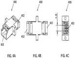
- FIG. 4Ais a perspective view of one embodiment of a narrow pitch LC adapter according to aspects of the present disclosure
- FIG. 4Bis a top view of the narrow pitch LC adapter of FIG. 4A ;
- FIG. 4Cis a front view of the narrow pitch LC adapter of FIG. 4A , showing a 4.8 mm pitch;
- FIG. 5is a perspective view of one embodiment of a narrow pitch LC duplex connector with remote release according to aspects of the present disclosure
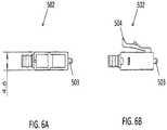
- FIG. 6Ais a top view of an LC connector used in the embodiment of FIG. 5 according to aspects of the present. disclosure
- FIG. 6Bis a side view of the LC connector of FIG. 6A according to aspects of the present disclosure
- FIG. 7is a perspective view of narrow pitch LC duplex connector of FIG. 5 , with the release mechanism being removed according to aspects of the present disclosure
- FIG. 8is a perspective disassembled view of the narrow pitch LC duplex connector of FIG. 5 according to aspects of the present disclosure
- FIG. 9is a perspective view of a prior art standard MPO SFP
- FIG. 10Ais a perspective view of a prior art standard MPO connector
- FIG. 10Bis a top view of the prior art MPO connector of FIG. 10A , having a width of 12.4 mm;
- FIG. 10Cis a front view of the prior art MPO connector of FIG. 10A ;
- FIG. 11is a perspective view of a future narrow width multi-fiber SFP for receiving connectors disclosed herein according to aspects of the present disclosure
- FIG. 12Ais a perspective view of one embodiment of a narrow width multi-fiber connector with remote release according to aspects of the present disclosure
- FIG. 12Bis a top view of the narrow width multi-fiber connector of FIG. 12A , having a width of 9.6 mm according to aspects of the present disclosure
- FIG. 12Cis a front view of the narrow width multi-fiber connector of FIG. 12A according to aspects of the present disclosure
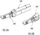
- FIG. 13Ais a perspective view of a narrow width multi-fiber connector inserted into a narrow width SFP having an SFP latch according to aspects of the present disclosure
- FIG. 13Bis a perspective view of a narrow width multi-fiber connector inserted into a narrow width adapter having an adapter latch according to aspects of the present disclosure
- FIG. 14is a side view of a narrow width multi-fiber connector of FIG. 13A having a recess engaged with an SFP latch in a normal pull tab position according to aspects of the present disclosure.
- FIG. 15is a side view of the narrow width multi-fiber connector of FIG. 13A , being disengaged from the SFP latch by retracting the pull tab according to aspects of the present disclosure.
- a connectorrefers to a device and/or components thereof that connects a first module or cable to a second module or cable.
- the connectormay be configured for fiber optic transmission or electrical signal transmission.
- the connectormay be any suitable type now known or later developed, such as, for example, a ferrule connector (FC), a fiber distributed data interface (FDDI) connector, an LC connector, a mechanical transfer (MT) connector, an SC connector, an SC duplex connector, or a straight tip (ST) connector.
- FCferrule connector
- FDDIfiber distributed data interface
- LCliquid crystal
- MTmechanical transfer
- SC connectorSC duplex connector
- STstraight tip
- the connectormay generally be defined by a connector housing body.
- the housing bodymay incorporate any or all of the components described herein.
- a “fiber optic cable” or an “optical cable”refers to a cable containing one or more optical fibers for conducting optical signals in beams of light.
- the optical fiberscan be constructed from any suitable transparent material, including glass, fiberglass, and plastic.
- the cablecan include a jacket or sheathing material surrounding the optical fibers.
- the cablecan be connected to a connector on one end or on both ends of the cable.
- Various embodiments described hereingenerally provide a remote release mechanism such that a user can remove cable assembly connectors that are closely spaced together on a high density panel without damaging surrounding connectors, accidentally disconnecting surrounding connectors, disrupting transmissions through surrounding connectors, and/or the like.
- Various embodimentsalso provide narrow pitch LC duplex connectors and narrow width multi-fiber connectors, for use, for example, with future narrow pitch LC SFPs and future narrow width SFPs.
- the remote release mechanismsallow use of the narrow pitch LC duplex connectors and narrow width multi-fiber connectors in dense arrays of narrow pitch LC SFPs and narrow width multi-fiber SFPs.
- FIG. 1Ashows a perspective view of a prior art standard 6.25 mm pitch LC connector SFP 100 .
- the SFP 100is configured to receive a duplex connector, and provides two receptacles 102 , each for receiving a respective LC connector.
- the pitch 104is defined as the axis-to-axis distance between the central longitudinal axes of each of the two receptacles 102 .
- FIG. 1Bshows a perspective view of a prior art standard 6.25 mm pitch LC adapter 106 .
- the adapter 106is also configured to receive a duplex connector, and provides two receptacles 108 , each for receiving a respective LC connector.
- FIG. 1Cis a top view of the adapter 106 of FIG.
- the pitch 110 of the adapter 106is defined similarly to that of the SFP 100 , as the axis-to-axis distance between the central longitudinal axes of each of the two receptacles 108 , as illustrated in FIG. 1D , which shows a front view of the adapter 106 .
- FIG. 2Ashows a prior art LC duplex connector 200 that may be used with the conventional SFP 100 and the conventional adapter 106 .
- the LC duplex connector 200includes two conventional LC connectors 202 .
- FIG. 2Bshows another prior art LC duplex connector 204 having a remote release pull tab 206 , and including two conventional LC connectors 208 .
- the remote release pull tabincludes two prongs 210 , each configured to couple to the extending member 212 of a respective LC connector 208 .
- FIGS. 2C and 2Dshow top and side views, respectively, of the conventional LC connector 208 , having a width of 5.6 mm, and further showing the extending member 212 .
- Various embodiments disclosed hereinare configured for use with a future SFP, such as the narrow pitch LC SFP 300 shown in FIG. 3 , having a pitch less than that of conventional 6.25 mm and 5.25 mm pitches.
- Various embodimentsutilize LC type fiber optic connectors in duplex arrangements (having transmitting and receiving fibers) but with a connector axis-to-axis distance that is less than the conventional 6.25 mm and 5.25 mm pitches, as described further below.
- FIGS. 4A to 4Cshow one embodiment of a narrow pitch adapter 400 .
- the narrow pitch adapter 400has receptacles 402 on opposite ends thereof, configured for mating two narrow pitch LC duplex connectors according to aspects disclosed herein.
- FIG. 4Bshows a top view of the adapter 400 .
- FIG. 4Cshows a front view, further illustrating that the adapter 400 has a pitch of 4.8 mm.
- the adapter 400is configured to receive a duplex LC connector, with a pitch of the adapter corresponding to the axis-to-axis distance between the LC connectors of the LC duplex connector.
- the adapter 400has a pitch of 4.8 mm
- various embodiments of narrow pitch adapters disclosed hereinmay have a different pitch that is less than that of the pitch of conventional adapters, for example less than 6.25 mm and less than about 5.25 mm.
- the pitchmay be about 4.8 mm or less.
- the interference between metal edges and burrsmay prevent the fiber optic connector's plastic latch from either becoming fully engaged or easily disengaged, especially with latches that are remotely triggered by pull tabs that project a distance behind the connector so as to keep fingers from disturbing adjacent optical fibers.
- various embodiments disclosed hereinadd a spring force to the remote latching component (pull tab), for example as shown and described in relation to FIGS. 5, 7, 8 and 12 below, to ensure that the connector latches are allowed to return to the undisplaced position and thereby become fully engaged inside the SFP's recess.
- FIG. 5shows one embodiment of a narrow pitch connector 500 according to aspects disclosed herein.
- the narrow pitch connector 500is a duplex LC connector including two LC connectors 502 .
- Each of the LC connectors 502includes a respective ferrule 503 and a respective extending member or latching arm 504 .
- the connector 500has a pitch of 4.8 mm, defined as the axis-to-axis distance between the central axes of the LC connectors 502 .
- the connector pitchmay be less than that of the pitch of conventional connectors, for example less than 6.25 mm and less than about 5.25 mm. In some embodiments, the pitch may be about 4.8 mm or less.
- the connector 500further includes a housing 506 having a bottom housing 508 and a top housing 510 .
- the bottom housing 508includes side walls 512 .
- the housing of the connectormay be a switchable housing.
- the side wallsmay be configured to open so as to facilitate opening of the housing, for example to change polarity of the connector.
- the side walls 512may be raised towards the rear of the connector, as shown in FIG. 5 .
- One advantage of raising the side walls towards the rear of the connectoris easier access. In other embodiments, the side walls may be raised at another location.
- the connector 500further includes a pull tab 514 having a distal end 516 and a proximal end 518 .
- the pull tab 514further includes a spring 520 configured to provide a force such that the connector latching arms 504 return to the undisplaced position and thereby become fully engaged inside the SFP's recess.
- the distal end 516 of the pull tab 514may be pulled to remotely release the connector 500 from an SFP or adapter.
- the proximal end 518 of the pull tab 514is uniquely shaped so as to engage with the unique profile of the latching arms 504 of the narrow pitch LC connector 500 .
- the proximal end 518engages both latching arms 504 of the duplex LC connector 500 .
- the proximal end 518includes a single prong configured to engage the latching arms of both connectors 502 .
- the pull tab 514At the proximal end 518 of the pull tab 514 there are outwardly pointing pins 522 configured to rest directly above and slide along the semi-circular surface of latching arms 504 of the duplex LC connectors 502 .
- the horizontal and rearward path direction of the pins 522causes the semi-circular profile of the connector latching arms 504 to flex downward.
- the pull tab 514can also be pushed down at a location directly behind the LC connectors 502 rather than pulling the tab in a rearward motion from a remote distance behind the connectors, such as from the distal end 516 .
- the action of pushing down the connectors' integral levers or latching arms 504unlatches the connector 500 .
- the horizontal motion of the pull tab 514may not be desirable.
- the connector latching arms 504may be pushed down without resulting in a horizontal motion of the pull tab 514 .
- FIGS. 6A and 6Bshow top and side views, respectively, of the LC connector 502 of the narrow pitch connector 500 .
- FIG. 6Afurther shows that the LC connector 502 has a width of 4.6 mm.
- FIG. 6Bshows the semi-circular profile of the latching arm 504 .
- FIG. 7shows a partially disassembled view of the narrow pitch connector 500 of FIG. 5 .
- the top housing 510is separated from the bottom housing 508 .
- the pull tab 514is coupled to the top housing 510 and configured to slide longitudinally along the length of the connector.
- the top housing 510also includes a restraint 524 configured to receive the pull tab 514 .
- FIG. 8shows a further disassembled view of the narrow pitch connector 500 .
- the pull tab 514is shown to be separated from the top housing 510 , and the spring 520 is removed from the pull tab.
- the pull tab 514includes a longitudinal recess 526 configured to receive the spring 520 , and at least one restraint 528 configured to retain the spring.
- the top housing 510also includes a recess 530 configured to accommodate at least a portion of the pull tab 514 , such as the spring 520 and the proximal end 518 .
- the pull tabmay be removably coupled to the connector via the top housing.
- FIG. 9shows a perspective view of a prior art standard MPO SFP 900 .
- the SFP 900is configured to receive a standard MPO connector, and provides a receptacle 902 for receiving an MPO connector having a conventional width, as shown for example in FIGS. 10A to 10C .
- FIG. 10Ashows a perspective view of a conventional MPO connector 1000 .
- the conventional MPO connector 1000has a width of 12.4 mm.
- FIG. 10Cshows a front view of the MPO connector 1000 .
- FIG. 11shows an embodiment of a future narrow width multi-fiber SFP 1100 according to aspects of the present disclosure.
- Various embodiments disclosed hereinare configured for use with the narrow width multi-fiber SFP 1100 , having a width less than that of conventional MPO connectors, that is less than about 12.4 mm.
- the narrow width multi-fiber SFPhas a receptacle 1102 configured to receive a narrow width multi-fiber connector, such as a narrow width connector having an MT ferrule.
- FIG. 12Ashows one embodiment of a narrow width connector 1200 according to aspects disclosed herein.
- the narrow width connector 1200is a multi-fiber connector including a multi-fiber MT/MPO ferrule 1202 .
- the connector 1200includes two extending members or latching arms 1204 . In other embodiments, the connector may include at least one latching arm.
- the connector 1200has a width of 9.6 mm, as shown in the top view of the connector 1200 in FIG. 12B .
- the connector widthmay be less than that of the width of conventional multi-fiber connectors, for example less than the 12.4 mm of the conventional MPO connector shown in FIG. 10B . In some embodiments, the width may be about 9.6 mm or less.
- the connector 1200further includes a housing 1206 having a bottom housing 1208 and a top housing 1210 .
- the bottom housing 1208includes side walls 1212 .
- the housing of the connectormay be a switchable housing.
- the side wallsmay be configured to open so as to facilitate opening of the housing, for example to change polarity of the connector.
- the side walls 1212may be raised towards the rear of the connector. One advantage of raising the side walls towards the rear of the connector is easier access.
- the side wallsmay also be raised at another location.
- the connector 1200further includes a pull tab 1214 having a distal end 1216 and a proximal end 1218 .
- the pull tab 1214further includes a spring 1220 configured to provide a force such that the connector latching arms 1204 return to the undisplaced position and thereby become fully engaged inside the SFP's recess.
- the distal end 1216 of the pull tab 1214may be pulled to remotely release the connector 1200 from an SEP or adapter.
- the proximal end 1218 of the pull tab 1214is uniquely shaped so as to engage with the unique profile of the latching arms 1204 of the narrow width multi-fiber connector 1200 .
- the proximal end 1218engages both latching arms 1204 of the multi-fiber connector 1200 .
- the proximal end 1218includes a single prong configured to engage the latching arms 1204 .
- the pull tab 1214there are outwardly pointing pins 1222 configured to rest directly above and slide along the semi-circular surface of latching arms 1204 .
- the horizontal and rearward path direction of the pins 1222causes the semi-circular profile of the connector latching arms 1204 to flex downward. Because the pins 1222 are not contained inside ramped grooves of the connector latching arms 1204 , the pull tab 1214 can also be pushed down at a location directly behind the latching arms 1204 rather than pulling the tab in a rearward motion from a remote distance behind the connector, such as from the distal end 1216 .
- the action of pushing down the connector's integral levers or latching arms 1204unlatches the connector 1200 .
- the horizontal motion of the pull tab 1214may not be desirable.
- the connector latching arms 1204may be pushed down without resulting in a horizontal motion of the pull tab 1214 .
- FIGS. 12B and 12Cshow top and front views, respectively, of the narrow width multi-fiber connector 1200 .
- FIG. 12Bfurther shows that the connector 1200 has a width of 9.6 mm.
- the narrow width connectorshave latching arms configured to engage with a fixed or immovable recess within a narrow width SFP or a narrow width adapter.
- the pull tab of the connectordisplaces the flexible latching arm of the connector so as to disengage the latching arm from the recess of the SFP or the adapter.
- the latching armsbend down as the pull tab is pulled back, so as to disengage the connector from the SFP or the adapter.
- the remote latch release pull tabmay be configured to couple with a latch or a hook within the adapter or the SFP.
- the flexible latching arm of the connectoris moved into the main cavity of the SFP or the adapter, and the latch of the SFP or the adapter engages a recess of the connector when the pull tab is in a normal location that is pushed forward by a spring.
- the pull tabmay be configured to have a ramp area such that when the pull tab is pulled back, the latch of the SFP or the adapter is lifted by the retracted pull tab, thereby disengaging the latch of the SFP or the adapter from the connector.
- FIG. 13Ashows a narrow pitch multi-fiber connector 1300 inserted into a narrow pitch SFP 1302 such that a recess of the connector engages an SFP latch.
- FIG. 13Bshows the narrow pitch connector 1300 inserted into a narrow pitch adapter 1304 such that a recess of the connector engages a latch of the adapter.
- FIG. 14shows a side view of the narrow width connector 1300 of FIG. 13A coupled to the narrow width SFP 1302 . Details of the coupling are shown within the circle 1400 .
- the SFP 1302includes an SFP latch 1402 .
- the connector 1300includes a recess 1404 .
- the connector housingmay comprise a recess 1404 .
- the pull tab 1406may be spring loaded as described in relation to various embodiments. This allows the pull tab 1406 to return to a position that will allow the SFP latch 1402 to engage with the connector recess 1404 .
- the pull tab 1406is in the normal pull tab location, that is pushed forward by a spring, as shown in FIG. 14 , the SFP latch 1402 is engaged with the connector recess 1404 as illustrated within the circle 1400 .
- FIG. 15shows a side view of the narrow width connector 1300 of FIG. 13A as it is disengaged from the narrow width SFP 1302 . Details of the decoupling are shown within the circle 1500 .
- the pull tab 1406includes a taper or a ramp area 1502 . As the pull tab 1406 is pulled back in the direction of the arrow 1504 as shown, the SFP latch 1402 is lifted by the ramp area of the retracted pull tab, thereby disengaging the SFP latch 1402 from the connector as illustrated within the circle 1500 .
- the same effect described herein in conjunction with FIG. 15also occurs in other embodiments of connectors coupled to a narrow width adapter as shown for example in FIG. 13A .
- FIGS. 14 and 15illustrate coupling of the connector to a narrow width SFP
- other embodiments of the connectormay be coupled to a narrow width adapter having an adapter latch, similar to that of the SFP latch.
- the embodiments shown in FIGS. 13 to 15include a narrow width multi-fiber connector, embodiments also work with narrow pitch LC connectors.
- compositions, methods, and devicesare described in terms of “comprising” various components or steps (interpreted as meaning “including, but not limited to”), the compositions, methods, and devices can also “consist essentially of” or “consist of” the various components and steps, and such terminology should be interpreted as defining essentially closed-member groups. It will be further understood by those within the art that if a specific number of an introduced claim recitation is intended, such an intent will be explicitly recited in the claim, and in the absence of such recitation no such intent is present. For example, as an aid to understanding, the following appended claims may contain usage of the introductory phrases “at least one” and “one or more” to introduce claim recitations.
- a rangeincludes each individual member.
- a group having 1-3 cellsrefers to groups having 1, 2, or 3 cells.
- a group having 1-5 cellsrefers to groups having 1, 2, 3, 4, or 5 cells, and so forth.
Landscapes
- Physics & Mathematics (AREA)
- General Physics & Mathematics (AREA)
- Optics & Photonics (AREA)
- Mechanical Coupling Of Light Guides (AREA)
Abstract
Description
Claims (10)
Priority Applications (3)
| Application Number | Priority Date | Filing Date | Title |
|---|---|---|---|
| US16/695,901US11152748B2 (en) | 2016-01-15 | 2019-11-26 | Narrow width adapters and connectors with pull tab release |
| US17/342,220US12222559B2 (en) | 2016-01-15 | 2021-06-08 | Narrow width adapters and connectors with pull tab release |
| US17/494,291US11415760B2 (en) | 2016-01-15 | 2021-10-05 | Narrow width adapters and connectors with pull tab release |
Applications Claiming Priority (8)
| Application Number | Priority Date | Filing Date | Title |
|---|---|---|---|
| USPCT/US16/13629 | 2016-01-15 | ||
| US14/996,865US9595786B1 (en) | 2016-01-15 | 2016-01-15 | Narrow width adapters and connectors with spring loaded remote release |
| PCT/US2016/013629WO2017123247A1 (en) | 2016-01-15 | 2016-01-15 | Narrow width adapters and connectors with spring loaded remote release |
| TW105101374ATW201725409A (en) | 2016-01-15 | 2016-01-18 | Narrow width adapters and connectors with spring loaded remote release |
| TW105101374 | 2016-01-18 | ||
| US15/044,838US10158194B2 (en) | 2016-01-15 | 2016-02-16 | Narrow width adapters and connectors with spring loaded remote release |
| US16/213,244US10520690B2 (en) | 2016-01-15 | 2018-12-07 | Narrow width adapters and connectors with pull tab release |
| US16/695,901US11152748B2 (en) | 2016-01-15 | 2019-11-26 | Narrow width adapters and connectors with pull tab release |
Related Parent Applications (1)
| Application Number | Title | Priority Date | Filing Date |
|---|---|---|---|
| US16/213,244ContinuationUS10520690B2 (en) | 2016-01-15 | 2018-12-07 | Narrow width adapters and connectors with pull tab release |
Related Child Applications (2)
| Application Number | Title | Priority Date | Filing Date |
|---|---|---|---|
| US17/342,220ContinuationUS12222559B2 (en) | 2016-01-15 | 2021-06-08 | Narrow width adapters and connectors with pull tab release |
| US17/494,291ContinuationUS11415760B2 (en) | 2016-01-15 | 2021-10-05 | Narrow width adapters and connectors with pull tab release |
Publications (2)
| Publication Number | Publication Date |
|---|---|
| US20200096716A1 US20200096716A1 (en) | 2020-03-26 |
| US11152748B2true US11152748B2 (en) | 2021-10-19 |
Family
ID=59312044
Family Applications (5)
| Application Number | Title | Priority Date | Filing Date |
|---|---|---|---|
| US15/044,838Expired - Fee RelatedUS10158194B2 (en) | 2016-01-15 | 2016-02-16 | Narrow width adapters and connectors with spring loaded remote release |
| US16/213,244ActiveUS10520690B2 (en) | 2016-01-15 | 2018-12-07 | Narrow width adapters and connectors with pull tab release |
| US16/695,901ActiveUS11152748B2 (en) | 2016-01-15 | 2019-11-26 | Narrow width adapters and connectors with pull tab release |
| US17/342,220Active2038-05-31US12222559B2 (en) | 2016-01-15 | 2021-06-08 | Narrow width adapters and connectors with pull tab release |
| US17/494,291ActiveUS11415760B2 (en) | 2016-01-15 | 2021-10-05 | Narrow width adapters and connectors with pull tab release |
Family Applications Before (2)
| Application Number | Title | Priority Date | Filing Date |
|---|---|---|---|
| US15/044,838Expired - Fee RelatedUS10158194B2 (en) | 2016-01-15 | 2016-02-16 | Narrow width adapters and connectors with spring loaded remote release |
| US16/213,244ActiveUS10520690B2 (en) | 2016-01-15 | 2018-12-07 | Narrow width adapters and connectors with pull tab release |
Family Applications After (2)
| Application Number | Title | Priority Date | Filing Date |
|---|---|---|---|
| US17/342,220Active2038-05-31US12222559B2 (en) | 2016-01-15 | 2021-06-08 | Narrow width adapters and connectors with pull tab release |
| US17/494,291ActiveUS11415760B2 (en) | 2016-01-15 | 2021-10-05 | Narrow width adapters and connectors with pull tab release |
Country Status (3)
| Country | Link |
|---|---|
| US (5) | US10158194B2 (en) |
| EP (1) | EP3427346A4 (en) |
| WO (1) | WO2017123264A1 (en) |
Cited By (2)
| Publication number | Priority date | Publication date | Assignee | Title |
|---|---|---|---|---|
| US20230341635A1 (en)* | 2022-04-20 | 2023-10-26 | Amphenol Corporation | Fiber optic connector plug and associated cable systems, cable assemblies, and method |
| US11934017B2 (en) | 2021-03-02 | 2024-03-19 | Corning Research & Development Corporation | Polarity changeable optical connector |
Families Citing this family (45)
| Publication number | Priority date | Publication date | Assignee | Title |
|---|---|---|---|---|
| MX372735B (en) | 2014-01-13 | 2020-06-19 | Tyco Electronics Shanghai Co Ltd | FIBER OPTIC CONNECTOR. |
| DE202014006815U1 (en)* | 2014-08-21 | 2014-09-09 | Rosenberger Hochfrequenztechnik Gmbh & Co. Kg | High current plug with clip closure |
| US9658409B2 (en) | 2015-03-03 | 2017-05-23 | Senko Advanced Components, Inc. | Optical fiber connector with changeable polarity |
| CN204719275U (en)* | 2015-06-09 | 2015-10-21 | 昂纳信息技术(深圳)有限公司 | A kind of QSFP+ module Straight pull unlocking structure |
| US10158194B2 (en) | 2016-01-15 | 2018-12-18 | Senko Advanced Components, Inc. | Narrow width adapters and connectors with spring loaded remote release |
| US9726830B1 (en)* | 2016-06-28 | 2017-08-08 | Senko Advanced Components, Inc. | Connector and adapter system for two-fiber mechanical transfer type ferrule |
| US10228521B2 (en) | 2016-12-05 | 2019-03-12 | Senko Advanced Components, Inc. | Narrow width adapters and connectors with modular latching arm |
| US10185100B2 (en)* | 2017-01-30 | 2019-01-22 | Senko Advanced Components, Inc | Modular connector and adapter assembly using a removable anchor device |
| CN106918869B (en)* | 2017-04-17 | 2018-10-26 | 深圳市飞博康光通讯技术有限公司 | A kind of LC duplexs connector |
| US11822133B2 (en) | 2017-07-14 | 2023-11-21 | Senko Advanced Components, Inc. | Ultra-small form factor optical connector and adapter |
| US12001064B2 (en) | 2017-07-14 | 2024-06-04 | Senko Advanced Components, Inc. | Small form factor fiber optic connector with multi-purpose boot |
| US10281669B2 (en) | 2017-07-14 | 2019-05-07 | Senko Advance Components, Inc. | Ultra-small form factor optical connectors |
| US10838152B2 (en) | 2017-11-17 | 2020-11-17 | Senko Advanced Components, Inc. | Ultra-small form factor optical connector having dual alignment keys |
| US10718911B2 (en) | 2017-08-24 | 2020-07-21 | Senko Advanced Components, Inc. | Ultra-small form factor optical connectors using a push-pull boot receptacle release |
| WO2019038641A1 (en)* | 2017-08-24 | 2019-02-28 | Senko Advanced Components, Inc. | Ultra-small form factor optical connectors using a push-pull boot receptacle release |
| US10830963B2 (en) | 2017-11-17 | 2020-11-10 | Commscope Technologies Llc | Fiber optic connector locking feature |
| US11002923B2 (en) | 2017-11-21 | 2021-05-11 | Senko Advanced Components, Inc. | Fiber optic connector with cable boot release having a two-piece clip assembly |
| US10623838B1 (en) | 2017-11-30 | 2020-04-14 | Amazon Technologies, Inc. | Optical transceivers with independently releasable fiber connectors |
| US11016250B2 (en)* | 2017-12-19 | 2021-05-25 | Us Conec, Ltd. | Mini duplex connector with push-pull polarity mechanism, carrier, and rail-receiving crimp body |
| US10634854B2 (en) | 2018-01-03 | 2020-04-28 | Afl Ig Llc | Push-pull boot connector for fiber optic cables |
| US10678000B2 (en)* | 2018-01-05 | 2020-06-09 | Senko Advanced Components, Inc. | Pull rod and alignment key for a fiber optic connector and adapter |
| EP3776038B1 (en) | 2018-03-28 | 2024-07-03 | Senko Advanced Components Inc. | Small form factor fiber optic connector with multi-purpose boot |
| USD879039S1 (en)* | 2018-06-07 | 2020-03-24 | Advanced-Connectek Inc. | Optical fiber connector |
| CN112088327A (en) | 2018-07-15 | 2020-12-15 | 扇港元器件股份有限公司 | Subminiature Optical Connectors and Adapters |
| US11073664B2 (en) | 2018-08-13 | 2021-07-27 | Senko Advanced Components, Inc. | Cable boot assembly for releasing fiber optic connector from a receptacle |
| WO2020055440A1 (en) | 2018-09-12 | 2020-03-19 | Senko Advanced Componetns, Inc. | Lc type connector with clip-on push/pull tab for releasing connector from a receptacle using a cable boot |
| US10921530B2 (en) | 2018-09-12 | 2021-02-16 | Senko Advanced Components, Inc. | LC type connector with push/pull assembly for releasing connector from a receptacle using a cable boot |
| US10921531B2 (en) | 2018-09-12 | 2021-02-16 | Senko Advanced Components, Inc. | LC type connector with push/pull assembly for releasing connector from a receptacle using a cable boot |
| US11806831B2 (en) | 2018-11-21 | 2023-11-07 | Senko Advanced Components, Inc. | Fixture and method for polishing fiber optic connector ferrules |
| US11175464B2 (en) | 2018-11-25 | 2021-11-16 | Senko Advanced Components, Inc. | Open ended spring body for use in an optical fiber connector |
| CN209561753U (en) | 2018-12-29 | 2019-10-29 | 泰科电子(上海)有限公司 | Electrical Connectors and Electrical Connector Assemblies |
| US10935736B2 (en) | 2019-02-25 | 2021-03-02 | Leviton Manufacturing Co., Inc. | Rotary clip for duplex polarity change |
| US12038613B2 (en) | 2019-03-28 | 2024-07-16 | Senko Advanced Components, Inc. | Behind-the-wall optical connector and assembly of the same |
| US11579379B2 (en) | 2019-03-28 | 2023-02-14 | Senko Advanced Components, Inc. | Fiber optic adapter assembly |
| US11340406B2 (en) | 2019-04-19 | 2022-05-24 | Senko Advanced Components, Inc. | Small form factor fiber optic connector with resilient latching mechanism for securing within a hook-less receptacle |
| US11036011B2 (en)* | 2019-04-23 | 2021-06-15 | Senko Advanced Components, Inc. | Fiber optic connector with multi-purpose release assembly configured for polarity change |
| WO2020252355A1 (en) | 2019-06-13 | 2020-12-17 | Senko Advanced Components, Inc | Lever actuated latch arm for releasing a fiber optic connector from a receptacle port and method of use |
| WO2020263678A1 (en) | 2019-06-25 | 2020-12-30 | The Siemon Compnay | Latch for telecommunications module |
| CN114600018B (en) | 2019-07-23 | 2024-04-09 | 扇港元器件有限公司 | Ultra-small receptacle for receiving a fiber optic connector opposite a ferrule assembly |
| CN111129867B (en) | 2019-11-06 | 2021-03-30 | 东莞立讯技术有限公司 | Pull belt connector |
| US12345925B2 (en) | 2020-05-29 | 2025-07-01 | Commscope Technologies Llc | Telecommunications connector with latch release mechanism |
| WO2022036119A1 (en)* | 2020-08-14 | 2022-02-17 | Commscope Technologies Llc | Connector push release |
| TWI784427B (en)* | 2020-11-13 | 2022-11-21 | 立佳興業股份有限公司 | Optical-electrical connector |
| CN216413414U (en)* | 2021-10-12 | 2022-04-29 | 东莞立讯技术有限公司 | Pull-strap connector and pull-strap connector assembly |
| US20250251550A1 (en)* | 2024-01-24 | 2025-08-07 | Senko Advanced Components, Inc. | Fiber optic connector and multifiber ferrule for fiber optic connector |
Citations (29)
| Publication number | Priority date | Publication date | Assignee | Title |
|---|---|---|---|---|
| US5674088A (en)* | 1995-03-07 | 1997-10-07 | Roche; Peter | Quick release connectors for electrical terminals |
| US5845036A (en) | 1996-08-08 | 1998-12-01 | Diamond Sa | Plug portion for an optical fiber connector |
| US5915987A (en) | 1997-09-19 | 1999-06-29 | Tektronix, Inc. | Latched electrical connector |
| US6276840B1 (en) | 1995-12-22 | 2001-08-21 | Stratos Lightwave, Inc. | Massive parallel optical interconnect system |
| US6343948B1 (en)* | 1998-06-26 | 2002-02-05 | Framatome Connectors International | Plug connector with snap-action closure |
| US20030063862A1 (en) | 2001-10-01 | 2003-04-03 | Woodhead Industries, Inc. | Holder for optical loopback assembly with release mechanism |
| US20030156796A1 (en) | 2002-02-19 | 2003-08-21 | Lakshman Rathnam | Connector housing for fiber-optic module |
| US6668113B2 (en) | 2001-09-19 | 2003-12-23 | Finisar Corporation | Compact optical assembly for optoelectronic transceivers |
| US7052186B1 (en) | 2005-06-08 | 2006-05-30 | Itt Manufacturing Enterprises, Inc. | Secondary latch sleeve for connector connections |
| US20060140543A1 (en) | 2004-12-29 | 2006-06-29 | Tyco Electronics Corporation | Connector and receptacle containing a physical security feature |
| US7234879B2 (en) | 2004-09-17 | 2007-06-26 | Finisar Corporation | Optical connector |
| US7473124B1 (en) | 2008-02-29 | 2009-01-06 | Tyco Electronics Corporation | Electrical plug assembly with bi-directional push-pull actuator |
| US20090220200A1 (en) | 2008-03-03 | 2009-09-03 | Avago Technologies Fiber Ip (Singapore) Pte. Ltd. | Optical transceiver module and duplex fiber optic connector |
| US20100239220A1 (en) | 2008-08-27 | 2010-09-23 | Protai Photonic Co., Ltd | One-piece lc type optical fiber adapter |
| US20110058773A1 (en) | 2008-05-07 | 2011-03-10 | Adrian Peterhans | Plug connector having unlocking mechanism |
| US20110267742A1 (en) | 2010-04-30 | 2011-11-03 | Finisar Corporation | Latching mechanism for an electronic module |
| US8113723B2 (en) | 2009-10-05 | 2012-02-14 | Finisar Corporation | Communications module integrated boot and release slide |
| US20120155810A1 (en) | 2010-12-17 | 2012-06-21 | Masaya Nakagawa | Duplex optical connector |
| US20120237177A1 (en) | 2011-03-17 | 2012-09-20 | Yuuji Minota | Locking mechanism of optical module |
| US20120273262A1 (en) | 2011-04-29 | 2012-11-01 | Innovation & Infinity Global Corp. | Transparent conductive structure applied to a touch panel and method of making the same |
| US8465317B2 (en) | 2011-10-05 | 2013-06-18 | Senko Advanced Components, Inc. | Latching connector with remote release |
| US8556645B2 (en) | 2012-01-23 | 2013-10-15 | Commscope, Inc. Of North Carolina | Delatching connector including extension member |
| US20140056562A1 (en) | 2012-08-24 | 2014-02-27 | Ridgemount Technologies Ltd. | Fiber Optic Connector |
| US20150030289A1 (en) | 2013-07-23 | 2015-01-29 | Amphenol Fiber Optic Technology (Shenzhen) | Clip device for facilitating insertion and removal of a push-pull fiber optic connector |
| US20150093083A1 (en) | 2013-10-02 | 2015-04-02 | Applied Optoelectronics, Inc. | Pluggable opticl transceiver module |
| US20150111417A1 (en) | 2013-10-23 | 2015-04-23 | Facebook, Inc. | Pull tab actuator for connectors |
| US20160116686A1 (en) | 2012-05-21 | 2016-04-28 | Advanced Fiber Products, LLC | Secure sc optical fiber connector and removal tools |
| US9541719B2 (en) | 2013-02-05 | 2017-01-10 | Sumitomo Electric Industries, Ltd. | Pluggable optical transceiver having pull-pull-tab |
| US9877413B2 (en) | 2013-11-12 | 2018-01-23 | Molex, Llc | Thermally configured connector system |
Family Cites Families (125)
| Publication number | Priority date | Publication date | Assignee | Title |
|---|---|---|---|---|
| US3733576A (en) | 1971-07-28 | 1973-05-15 | J Cooper | Reversible safety ground plug |
| US4645295A (en) | 1980-02-04 | 1987-02-24 | Allied Corporation | Fiber optic connector |
| US5181267A (en) | 1988-02-23 | 1993-01-19 | Amp Incorporated | Sheath connector for an optical cable |
| US5673346A (en) | 1989-11-24 | 1997-09-30 | Nippon Telegraph And Telephone Corporation | Optical jack for plug-jack optical connector |
| US5222168A (en) | 1990-12-13 | 1993-06-22 | The Furukawa Electric Co., Ltd. | Method for stacking ferrules of a stacked-type optical connector and a stacked-type optical connector |
| JP2573482Y2 (en) | 1992-04-08 | 1998-05-28 | ヒロセ電機株式会社 | 2-core optical connector |
| US5390272A (en) | 1993-08-31 | 1995-02-14 | Amphenol Corporation | Fiber optic cable connector with strain relief boot |
| US5528712A (en) | 1995-02-06 | 1996-06-18 | Belenkiy; Yuriy | Duplex connector |
| US5615293A (en) | 1996-01-30 | 1997-03-25 | W. L. Gore & Associates, Inc. | Fiber optic cable assembly for facilitating the installation thereof in a structure |
| US5719977A (en) | 1996-04-23 | 1998-02-17 | Lucent Technologies Inc. | Optical connector with immovable ferrule |
| DE19728960C1 (en) | 1997-06-30 | 2000-07-06 | Siemens Ag | Optical multiple connector |
| WO2000046624A1 (en) | 1997-08-07 | 2000-08-10 | The Furukawa Electric Co. Ltd. | Structure for collectively joining plurality of optical connectors together, device for arranging optical connectors, and adapter for optical connectors |
| JP3886610B2 (en) | 1997-08-29 | 2007-02-28 | 株式会社フジクラ | Optical connector |
| WO1999028774A1 (en) | 1997-11-28 | 1999-06-10 | Siemens Aktiengesellschaft | Optical connection system |
| US5915058A (en) | 1998-01-05 | 1999-06-22 | Molex Incorporated | Fiber optic connector assembly |
| US6224268B1 (en) | 1998-04-23 | 2001-05-01 | The Whitaker Corporation | Plug housing with attached cantilevered latch for a fiber optic connector |
| US6149313A (en) | 1998-12-31 | 2000-11-21 | Siecor Operations, Llc | Gender selectable fiber optic connector and associated fabrication method |
| JP3825930B2 (en) | 1999-01-28 | 2006-09-27 | ヒロセ電機株式会社 | Optical connector |
| KR100677065B1 (en) | 1999-04-29 | 2007-02-01 | 삼성전자주식회사 | Optical connector module |
| JP2001147346A (en) | 1999-11-19 | 2001-05-29 | Yazaki Corp | Female connector |
| US6419399B1 (en) | 1999-12-01 | 2002-07-16 | 3M Innovative Properties Company | Optical fiber connector system |
| US6331079B1 (en) | 1999-12-07 | 2001-12-18 | Molex Incorporated | Mounting system for a connector assembly to a substrate |
| US6511230B1 (en) | 2000-02-04 | 2003-01-28 | Panduit Corp. | Fiber optic connection system |
| JP3765962B2 (en) | 2000-04-26 | 2006-04-12 | 株式会社フジクラ | Optical connector |
| US6305961B1 (en) | 2000-07-12 | 2001-10-23 | Molex Incorporated | EMI gasket for connector assemblies |
| EP1337883B1 (en) | 2000-11-21 | 2004-09-29 | Euromicron Werkzeuge GmbH | Connector for optical waveguides comprising a connector housing |
| US6796715B2 (en) | 2001-04-14 | 2004-09-28 | E20 Communications, Inc. | Fiber optic modules with pull-action de-latching mechanisms |
| US6568861B2 (en) | 2001-05-16 | 2003-05-27 | Fci Americas Technology, Inc. | Fiber optic adapter |
| US6891735B2 (en) | 2001-12-14 | 2005-05-10 | Tyco Electronics Corporation | EMI shielded adapter for fiber optic connector systems |
| US20030118293A1 (en) | 2001-12-21 | 2003-06-26 | Tyco Electronics Corporation | Snap together optoelectronic module |
| EP1343038A1 (en) | 2002-03-09 | 2003-09-10 | Agilent Technologies, Inc. - a Delaware corporation - | Hot-pluggable opto-electronic module with gasket for EMI-shielding |
| US20050135753A1 (en) | 2002-03-14 | 2005-06-23 | Daniel Eigenmann | Fibre-optic plug-in connector system |
| CN2567816Y (en) | 2002-09-03 | 2003-08-20 | 鸿富锦精密工业(深圳)有限公司 | Plug connector |
| US6976303B2 (en) | 2002-10-24 | 2005-12-20 | Molex Incorporated | System and tool for mounting a connecting device to a substrate |
| US6764222B1 (en) | 2003-01-16 | 2004-07-20 | Molex Incorporated | Fiber optic connector assembly |
| US6918704B2 (en) | 2003-01-30 | 2005-07-19 | Panduit Corp. | Tunable fiber optic connector |
| US6715928B1 (en) | 2003-02-27 | 2004-04-06 | Molex Incorporated | Connector panel mount system |
| US20040247252A1 (en) | 2003-02-28 | 2004-12-09 | John Ehrenreich | Retractable fiber optic connector housing |
| WO2004081614A2 (en) | 2003-03-06 | 2004-09-23 | Tyco Electronics Corporation | Connector assembly clip |
| US7001081B2 (en) | 2003-05-22 | 2006-02-21 | 3M Innovative Properties Company | Strain relief boot with flexible extension for guiding fiber optic cable |
| JP2004354693A (en) | 2003-05-29 | 2004-12-16 | Suncall Corp | Optical connector |
| US6910910B2 (en) | 2003-08-26 | 2005-06-28 | Ocean Design, Inc. | Dry mate connector |
| US20050111796A1 (en) | 2003-11-26 | 2005-05-26 | Matasek Jeffrey A. | Adaptor for reducing EMI |
| US7290941B2 (en) | 2003-12-23 | 2007-11-06 | Amphenol Corporation | Modular fiber optic connector system |
| US7008117B2 (en) | 2003-12-23 | 2006-03-07 | Amphenol Corporation | Optical connector assembly with features for ease of use |
| US7204644B2 (en) | 2004-03-24 | 2007-04-17 | Corning Cable Systems Llc | Field installable optical fiber connector |
| US20050281509A1 (en) | 2004-06-18 | 2005-12-22 | 3M Innovative Properties Company | Optical connector system with EMI shielding |
| US7347634B2 (en) | 2004-08-06 | 2008-03-25 | Finisar Corporation | Opto-electrical module for optical signals from at least two optical data channels for arranging on a main circuit board of a component assembly and opto-electrical component assembly |
| JP4758433B2 (en) | 2004-10-22 | 2011-08-31 | パンドウィット・コーポレーション | Push plug and tool |
| US7284912B2 (en) | 2005-01-12 | 2007-10-23 | Illum Technologies, Inc. | Multi fiber optical interconnect system, with push—push type insertion/withdrawal mechanism, MT-type connector and shuttered adapter and method for using same |
| US7150567B1 (en) | 2005-05-27 | 2006-12-19 | Corning Cable Systems Llc | Fiber optic connector having keyed ferrule holder |
| US7677812B2 (en) | 2006-07-31 | 2010-03-16 | Tyco Electronics Corporation | Strain relief boot for cable connector |
| US7646615B2 (en) | 2006-12-19 | 2010-01-12 | Finisar Corporation | Electromagnetic inferference shield for an optoelectronic module |
| US20080260333A1 (en) | 2007-04-23 | 2008-10-23 | Roth Richard F | Replacement optical connector |
| US7628545B2 (en) | 2007-06-18 | 2009-12-08 | Corning Cable Systems Llc | Fiber optic plug assembly with boot and crimp band |
| DE102007033246A1 (en) | 2007-07-17 | 2009-01-22 | Euromicron Werkzeuge Gmbh | Plug for terminating optical transmission media |
| US8559781B2 (en) | 2008-11-07 | 2013-10-15 | Us Conec, Ltd. | Removable sleeve for fiber optic connectors for high density applications |
| US20100284656A1 (en) | 2009-05-07 | 2010-11-11 | Ofs Fitel, Llc | Short profile optical connector |
| JP5574469B2 (en) | 2009-05-25 | 2014-08-20 | 日本航空電子工業株式会社 | Optical connector and optical connector system |
| CN101988976B (en) | 2009-08-05 | 2012-10-03 | 华为技术有限公司 | Miniature double-core optical fiber connector |
| US8152384B2 (en) | 2009-10-15 | 2012-04-10 | Corning Cable Systems Llc | Push-pull fiber optic connectors and methods for making the same |
| WO2011089003A1 (en) | 2010-01-22 | 2011-07-28 | Leoni Kabel Holding Gmbh | Plug element having a locking mechanism |
| US8406597B2 (en) | 2010-02-16 | 2013-03-26 | Commscope, Inc. Of North Carolina | Intelligent fiber optic adapter mounting structures that receive and correctly position multiple types of fiber optic adapters and related adapter collars and bulkheads |
| US8858089B2 (en) | 2010-03-16 | 2014-10-14 | Ofs Fitel, Llc | Single-fiber connectors for optical fiber cables |
| US9366829B2 (en) | 2010-03-16 | 2016-06-14 | Ofs Fitel, Llc | Multi-ferrule connector for multicore fiber terminations |
| JP4995305B2 (en) | 2010-06-04 | 2012-08-08 | サンコール株式会社 | 2-core optical connector unit |
| US8308377B2 (en)* | 2010-07-27 | 2012-11-13 | Avago Technologies Fiber Ip (Singapore) Pte. Ltd. | Delatch device having both push and pull operability for use with an optical transceiver module, and a method |
| CN201740886U (en) | 2010-08-06 | 2011-02-09 | 华为技术有限公司 | Dual-core optical fiber connector |
| JP2012053375A (en) | 2010-09-03 | 2012-03-15 | Sanwa Denki Kogyo Co Ltd | Multilink optical connector |
| JP5501166B2 (en) | 2010-09-03 | 2014-05-21 | 株式会社フジクラ | Optical connector and optical communication system |
| JP5439319B2 (en) | 2010-09-06 | 2014-03-12 | 株式会社フジクラ | Optical connector and optical connector insertion / extraction method |
| JP5735248B2 (en) | 2010-09-30 | 2015-06-17 | 株式会社フジクラ | Optical connector, optical connector connection method, connector adapter, optical line, optical communication system |
| US8636424B2 (en) | 2010-10-22 | 2014-01-28 | Panduit Corp. | Optical communication connector |
| US8662760B2 (en) | 2010-10-29 | 2014-03-04 | Corning Cable Systems Llc | Fiber optic connector employing optical fiber guide member |
| ES2402632B1 (en)* | 2011-02-08 | 2014-05-14 | Tyco Electronics Raychem Bvba | RELEASE TONGUE FOR AN ELECTRICAL CONNECTOR AND ELECTRICAL CONNECTOR THAT INCLUDES SUCH RELEASE TONGUE |
| US8684611B2 (en) | 2011-02-22 | 2014-04-01 | Us Conec, Ltd. | Two-piece spring push for fiber optic connectors with large diameter fiber optic cables |
| US8636425B2 (en) | 2011-03-15 | 2014-01-28 | Adc Telecommunications, Inc. | Fiber optic connector |
| WO2012151175A2 (en) | 2011-05-04 | 2012-11-08 | The Siemon Company | Fiber optic connector with polarity change |
| US8764308B2 (en) | 2011-06-06 | 2014-07-01 | Panduit Corp. | Duplex clip assembly for fiber optic connectors |
| TWM449965U (en) | 2011-06-14 | 2013-04-01 | Molex Inc | Ferrule assembly with integral latch |
| US8540435B2 (en) | 2011-07-22 | 2013-09-24 | Corning Cable Systems Llc | Ferrule retainers having access window(s) for accessing and/or referencing a fiber optic ferrule, and related fiber optic connector assemblies, connectors, and referencing methods |
| US20130094816A1 (en) | 2011-10-18 | 2013-04-18 | Senko Advanced Components, Inc. | Flexibly bended boot for optical fiber connector |
| US8784122B2 (en) | 2011-11-14 | 2014-07-22 | Airborn, Inc. | Low-profile right-angle electrical connector assembly |
| WO2013100892A1 (en) | 2011-12-27 | 2013-07-04 | Yazaki Corporation | Optical module |
| TWI435130B (en) | 2012-02-20 | 2014-04-21 | Ezontek Technologies Co Ltd | Fiber optic connector and device for unplugging auxiliary fiber connector |
| US20130308916A1 (en) | 2012-05-16 | 2013-11-21 | Scott Eaker Buff | High-density port tap fiber optic modules, and related systems and methods for monitoring optical networks |
| US8770863B2 (en) | 2012-06-04 | 2014-07-08 | Corning Cable Systems Llc | Multi-fiber fiber-optic connector with switchable polarity key |
| US8858090B2 (en) | 2012-06-05 | 2014-10-14 | Corning Cable Systems Llc | Ferrule holders with an integral lead-in tube employed in fiber optic connector assemblies, and related components, connectors, and methods |
| GB2506884B (en) | 2012-10-10 | 2017-04-12 | Fibrefab Ltd | Fibre optic connector device |
| US9297976B2 (en) | 2012-11-14 | 2016-03-29 | Clearfield, Inc. | Optical fiber connector |
| US20140241689A1 (en) | 2013-02-28 | 2014-08-28 | Corning Cable Systems Llc | Ganged fiber optic connector adapter modules and assemblies having reinforcement members and staggered fiber optic connector adapter ports |
| US9857538B2 (en) | 2013-03-15 | 2018-01-02 | Us Conec, Ltd. | Alignment adapter and alignment design for a connector therefor |
| CN203326271U (en) | 2013-06-20 | 2013-12-04 | 宁波卓新通讯接插件有限公司 | Network connector which can be pulled out easily |
| TWI628672B (en) | 2013-08-21 | 2018-07-01 | 克里斯多福B 雪羅 | Networking cables for transmitting data and method of assembling a connector for a networking cable |
| CN104849816B (en) | 2014-02-14 | 2017-01-11 | 泰科电子(上海)有限公司 | Optical fiber connector and assembly method therefor |
| CN104849815B (en) | 2014-02-14 | 2017-01-18 | 泰科电子(上海)有限公司 | Optical fiber connector and assembly method therefor |
| US9829645B2 (en) | 2014-06-30 | 2017-11-28 | Nexans | Reversible polarity MPO fiber optic connector |
| US9599778B2 (en) | 2014-10-22 | 2017-03-21 | Senko Advanced Components, Inc. | Latching connector with remote release |
| US9411111B2 (en) | 2014-12-09 | 2016-08-09 | Sae Magnetics (H.K.) Ltd. | Pluggable optical connector, lock and release mechanism therefor |
| JP6475974B2 (en) | 2014-12-25 | 2019-02-27 | 住友電気工業株式会社 | Receptacle connector and optical coupling structure |
| US9568689B2 (en) | 2015-02-18 | 2017-02-14 | US Conec, Ltd | Spring push and push-pull tab for tightly spaced fiber optic connectors |
| GB2538089B (en) | 2015-05-06 | 2019-06-19 | Fibrefab Ltd | Fibre optic cable assembly |
| US9870215B2 (en) | 2015-11-30 | 2018-01-16 | International Business Machines Corporation | Tracking an application installation state |
| US10158194B2 (en) | 2016-01-15 | 2018-12-18 | Senko Advanced Components, Inc. | Narrow width adapters and connectors with spring loaded remote release |
| US9678283B1 (en) | 2016-01-15 | 2017-06-13 | Senko Advanced Components, Inc. | Fiber optic connector assemblies with adjustable polarity |
| US10191227B2 (en) | 2016-01-20 | 2019-01-29 | Alliance Fiber Optics Products, Inc. | Fiber optic connector with small profile, and cable assemblies, systems, and methods including the same |
| WO2017127208A1 (en) | 2016-01-20 | 2017-07-27 | Alliance Fiber Optic Products, Inc. | Fiber optic connector with small profile, and cable assemblies, systems, and methods including the same |
| MX2018009596A (en) | 2016-02-09 | 2019-03-21 | Alliance Fiber Optics Prod Inc | Fiber optic connector with dual multi-fiber ferrules, and cable assemblies and systems including the same. |
| US10156683B2 (en) | 2016-04-11 | 2018-12-18 | Leviton Manufacturing Co., Inc. | Polarity identification for polarity reversing duplex unibody connectors |
| US9625658B1 (en) | 2016-04-12 | 2017-04-18 | Jyh Eng Technology Co., Ltd. | Communication connector with alterable polarity |
| JP2019519809A (en) | 2016-05-27 | 2019-07-11 | フィニサー コーポレイション | Duplex mini LC connector |
| DE202016103178U1 (en) | 2016-06-16 | 2016-07-07 | Reichle & De-Massari Ag | Connectors |
| JP2018036477A (en) | 2016-08-31 | 2018-03-08 | 住友電気工業株式会社 | Optical connection structure |
| US11333836B2 (en) | 2017-01-30 | 2022-05-17 | Senko Advanced Components, Inc. | Adapter for optical connectors |
| CN110249248B (en) | 2017-01-30 | 2021-07-27 | 扇港元器件股份有限公司 | Optical connectors with reversible polarity |
| TWM548279U (en) | 2017-03-03 | 2017-09-01 | 光聖科技(寧波)有限公司 | High density optical fiber connector |
| US10281669B2 (en) | 2017-07-14 | 2019-05-07 | Senko Advance Components, Inc. | Ultra-small form factor optical connectors |
| US11016250B2 (en) | 2017-12-19 | 2021-05-25 | Us Conec, Ltd. | Mini duplex connector with push-pull polarity mechanism, carrier, and rail-receiving crimp body |
| US10634854B2 (en) | 2018-01-03 | 2020-04-28 | Afl Ig Llc | Push-pull boot connector for fiber optic cables |
| EP3776038B1 (en) | 2018-03-28 | 2024-07-03 | Senko Advanced Components Inc. | Small form factor fiber optic connector with multi-purpose boot |
| US11719893B2 (en) | 2018-04-06 | 2023-08-08 | Us Conec Ltd. | Flexible push-pull boot and crimp body for fiber optic connector |
| US11428875B2 (en) | 2019-01-25 | 2022-08-30 | Us Conec Ltd. | Single port blindmate for fiber optic connectors |
| CN118226586A (en) | 2019-09-13 | 2024-06-21 | 美国康涅克有限公司 | Multi-ferrule angled polishing connector with simplified polarity inversion |
| US10809480B1 (en) | 2019-09-30 | 2020-10-20 | Corning Research & Development Corporation | Dense wavelength division multiplexing fiber optic apparatuses and related equipment |
| EP4136488B1 (en) | 2020-04-15 | 2025-10-08 | Corning Research & Development Corporation | An interconnect system and methods of installing the same |
- 2016
- 2016-02-16USUS15/044,838patent/US10158194B2/ennot_activeExpired - Fee Related
- 2016-02-18EPEP16885363.8Apatent/EP3427346A4/enactivePending
- 2016-02-18WOPCT/US2016/018476patent/WO2017123264A1/ennot_activeCeased
- 2018
- 2018-12-07USUS16/213,244patent/US10520690B2/enactiveActive
- 2019
- 2019-11-26USUS16/695,901patent/US11152748B2/enactiveActive
- 2021
- 2021-06-08USUS17/342,220patent/US12222559B2/enactiveActive
- 2021-10-05USUS17/494,291patent/US11415760B2/enactiveActive
Patent Citations (30)
| Publication number | Priority date | Publication date | Assignee | Title |
|---|---|---|---|---|
| US5674088A (en)* | 1995-03-07 | 1997-10-07 | Roche; Peter | Quick release connectors for electrical terminals |
| US6276840B1 (en) | 1995-12-22 | 2001-08-21 | Stratos Lightwave, Inc. | Massive parallel optical interconnect system |
| US5845036A (en) | 1996-08-08 | 1998-12-01 | Diamond Sa | Plug portion for an optical fiber connector |
| US5915987A (en) | 1997-09-19 | 1999-06-29 | Tektronix, Inc. | Latched electrical connector |
| US6343948B1 (en)* | 1998-06-26 | 2002-02-05 | Framatome Connectors International | Plug connector with snap-action closure |
| US6668113B2 (en) | 2001-09-19 | 2003-12-23 | Finisar Corporation | Compact optical assembly for optoelectronic transceivers |
| US20030063862A1 (en) | 2001-10-01 | 2003-04-03 | Woodhead Industries, Inc. | Holder for optical loopback assembly with release mechanism |
| US20030156796A1 (en) | 2002-02-19 | 2003-08-21 | Lakshman Rathnam | Connector housing for fiber-optic module |
| US7234879B2 (en) | 2004-09-17 | 2007-06-26 | Finisar Corporation | Optical connector |
| US20060140543A1 (en) | 2004-12-29 | 2006-06-29 | Tyco Electronics Corporation | Connector and receptacle containing a physical security feature |
| US7052186B1 (en) | 2005-06-08 | 2006-05-30 | Itt Manufacturing Enterprises, Inc. | Secondary latch sleeve for connector connections |
| US7473124B1 (en) | 2008-02-29 | 2009-01-06 | Tyco Electronics Corporation | Electrical plug assembly with bi-directional push-pull actuator |
| US20090220200A1 (en) | 2008-03-03 | 2009-09-03 | Avago Technologies Fiber Ip (Singapore) Pte. Ltd. | Optical transceiver module and duplex fiber optic connector |
| US20110058773A1 (en) | 2008-05-07 | 2011-03-10 | Adrian Peterhans | Plug connector having unlocking mechanism |
| US20100239220A1 (en) | 2008-08-27 | 2010-09-23 | Protai Photonic Co., Ltd | One-piece lc type optical fiber adapter |
| US8113723B2 (en) | 2009-10-05 | 2012-02-14 | Finisar Corporation | Communications module integrated boot and release slide |
| US20110267742A1 (en) | 2010-04-30 | 2011-11-03 | Finisar Corporation | Latching mechanism for an electronic module |
| US20120155810A1 (en) | 2010-12-17 | 2012-06-21 | Masaya Nakagawa | Duplex optical connector |
| US20120237177A1 (en) | 2011-03-17 | 2012-09-20 | Yuuji Minota | Locking mechanism of optical module |
| US20120273262A1 (en) | 2011-04-29 | 2012-11-01 | Innovation & Infinity Global Corp. | Transparent conductive structure applied to a touch panel and method of making the same |
| US8465317B2 (en) | 2011-10-05 | 2013-06-18 | Senko Advanced Components, Inc. | Latching connector with remote release |
| US8556645B2 (en) | 2012-01-23 | 2013-10-15 | Commscope, Inc. Of North Carolina | Delatching connector including extension member |
| US20160116686A1 (en) | 2012-05-21 | 2016-04-28 | Advanced Fiber Products, LLC | Secure sc optical fiber connector and removal tools |
| US20140056562A1 (en) | 2012-08-24 | 2014-02-27 | Ridgemount Technologies Ltd. | Fiber Optic Connector |
| US9541719B2 (en) | 2013-02-05 | 2017-01-10 | Sumitomo Electric Industries, Ltd. | Pluggable optical transceiver having pull-pull-tab |
| US20150030289A1 (en) | 2013-07-23 | 2015-01-29 | Amphenol Fiber Optic Technology (Shenzhen) | Clip device for facilitating insertion and removal of a push-pull fiber optic connector |
| US20150093083A1 (en) | 2013-10-02 | 2015-04-02 | Applied Optoelectronics, Inc. | Pluggable opticl transceiver module |
| US9523826B2 (en) | 2013-10-02 | 2016-12-20 | Applied Optoelectronics, Inc. | Pluggable optical transceiver module |
| US20150111417A1 (en) | 2013-10-23 | 2015-04-23 | Facebook, Inc. | Pull tab actuator for connectors |
| US9877413B2 (en) | 2013-11-12 | 2018-01-23 | Molex, Llc | Thermally configured connector system |
Non-Patent Citations (7)
| Title |
|---|
| Chinese Office Action issued for Application No. 201680082441.8, dated May 27, 2019, 7 pages. |
| Extended European Search Report issued for Application No. 16885363.8, dated Feb. 18, 2020, 10 pages. |
| International Search Report and Written Opinion dated Mar. 17, 2016 from International Application No. PCT/US2016/013629, International Filing Date Jan. 15, 2016, 8 pages. |
| International Search Report and Written Opinion dated May 6, 2016 from International Application No. PCT/US2016/018476, International Filing Date Feb. 18, 2016, 8 pages. |
| Partial Supplementary European Search Report issued for Application No. 16885363.8, dated Nov. 18, 2019, 10 pages. |
| Second Chinese Office Action issued for Application No. 201680082441.8, dated Aug. 29, 2019, 8 pages. |
| Shimoji et al., "Development of Mini-MPO Connector," Furukawa Review, 1999 (available online since at least Jul. 16, 2011). |
Cited By (3)
| Publication number | Priority date | Publication date | Assignee | Title |
|---|---|---|---|---|
| US11934017B2 (en) | 2021-03-02 | 2024-03-19 | Corning Research & Development Corporation | Polarity changeable optical connector |
| US20230341635A1 (en)* | 2022-04-20 | 2023-10-26 | Amphenol Corporation | Fiber optic connector plug and associated cable systems, cable assemblies, and method |
| US11835774B2 (en)* | 2022-04-20 | 2023-12-05 | Amphenol Corporation | Fiber optic connector plug and associated cable systems, cable assemblies, and method |
Also Published As
| Publication number | Publication date |
|---|---|
| US20210296824A1 (en) | 2021-09-23 |
| EP3427346A4 (en) | 2020-03-18 |
| EP3427346A1 (en) | 2019-01-16 |
| US10520690B2 (en) | 2019-12-31 |
| US10158194B2 (en) | 2018-12-18 |
| US20170205591A1 (en) | 2017-07-20 |
| US12222559B2 (en) | 2025-02-11 |
| US20190181586A1 (en) | 2019-06-13 |
| US20220029356A1 (en) | 2022-01-27 |
| US11415760B2 (en) | 2022-08-16 |
| WO2017123264A1 (en) | 2017-07-20 |
| US20200096716A1 (en) | 2020-03-26 |
Similar Documents
| Publication | Publication Date | Title |
|---|---|---|
| US11152748B2 (en) | Narrow width adapters and connectors with pull tab release | |
| US9595786B1 (en) | Narrow width adapters and connectors with spring loaded remote release | |
| US11703648B2 (en) | Adapter | |
| US11500164B2 (en) | LC type connector with push/pull assembly for releasing connector from a receptacle using a cable boot | |
| US10921530B2 (en) | LC type connector with push/pull assembly for releasing connector from a receptacle using a cable boot | |
| US11112566B2 (en) | Removal tool for removing a plural of micro optical connectors from an adapter interface | |
| US11086087B2 (en) | LC type connector with clip-on push/pull tab for releasing connector from a receptacle using a cable boot | |
| CN108701937B (en) | Narrow width connector and adapter with spring loaded remote release mechanism | |
| WO2017123247A1 (en) | Narrow width adapters and connectors with spring loaded remote release | |
| CN111239928B (en) | Narrow width connector and adapter with spring loaded remote release mechanism | |
| TW201725409A (en) | Narrow width adapters and connectors with spring loaded remote release |
Legal Events
| Date | Code | Title | Description |
|---|---|---|---|
| FEPP | Fee payment procedure | Free format text:ENTITY STATUS SET TO UNDISCOUNTED (ORIGINAL EVENT CODE: BIG.); ENTITY STATUS OF PATENT OWNER: SMALL ENTITY | |
| FEPP | Fee payment procedure | Free format text:ENTITY STATUS SET TO SMALL (ORIGINAL EVENT CODE: SMAL); ENTITY STATUS OF PATENT OWNER: SMALL ENTITY | |
| STPP | Information on status: patent application and granting procedure in general | Free format text:NON FINAL ACTION MAILED | |
| STPP | Information on status: patent application and granting procedure in general | Free format text:RESPONSE TO NON-FINAL OFFICE ACTION ENTERED AND FORWARDED TO EXAMINER | |
| STPP | Information on status: patent application and granting procedure in general | Free format text:FINAL REJECTION MAILED | |
| STPP | Information on status: patent application and granting procedure in general | Free format text:DOCKETED NEW CASE - READY FOR EXAMINATION | |
| STPP | Information on status: patent application and granting procedure in general | Free format text:NOTICE OF ALLOWANCE MAILED -- APPLICATION RECEIVED IN OFFICE OF PUBLICATIONS | |
| STPP | Information on status: patent application and granting procedure in general | Free format text:NOTICE OF ALLOWANCE MAILED -- APPLICATION RECEIVED IN OFFICE OF PUBLICATIONS | |
| STPP | Information on status: patent application and granting procedure in general | Free format text:PUBLICATIONS -- ISSUE FEE PAYMENT VERIFIED | |
| STCF | Information on status: patent grant | Free format text:PATENTED CASE | |
| AS | Assignment | Owner name:SENKO ADVANCED COMPONENTS, INC., MASSACHUSETTS Free format text:ASSIGNMENT OF ASSIGNORS INTEREST;ASSIGNOR:GNIADEK, JEFFREY;REEL/FRAME:062557/0588 Effective date:20221223 | |
| AS | Assignment | Owner name:SENKO ADVANCED COMPONENTS, INC., MASSACHUSETTS Free format text:ASSIGNMENT OF ASSIGNORS INTEREST;ASSIGNORS:TAKANO, KAZUYOSHI;GNIADEK, JEFFREY;REEL/FRAME:064420/0857 Effective date:20160115 | |
| FEPP | Fee payment procedure | Free format text:ENTITY STATUS SET TO UNDISCOUNTED (ORIGINAL EVENT CODE: BIG.); ENTITY STATUS OF PATENT OWNER: LARGE ENTITY | |
| MAFP | Maintenance fee payment | Free format text:PAYMENT OF MAINTENANCE FEE, 4TH YEAR, LARGE ENTITY (ORIGINAL EVENT CODE: M1551); ENTITY STATUS OF PATENT OWNER: LARGE ENTITY Year of fee payment:4 |