US11152555B2 - Underwater energy harvesting drone and method for operation - Google Patents
Underwater energy harvesting drone and method for operationDownload PDFInfo
- Publication number
- US11152555B2 US11152555B2US15/894,613US201815894613AUS11152555B2US 11152555 B2US11152555 B2US 11152555B2US 201815894613 AUS201815894613 AUS 201815894613AUS 11152555 B2US11152555 B2US 11152555B2
- Authority
- US
- United States
- Prior art keywords
- primary hull
- thermoelectric modules
- electrical power
- storage device
- storage tank
- Prior art date
- Legal status (The legal status is an assumption and is not a legal conclusion. Google has not performed a legal analysis and makes no representation as to the accuracy of the status listed.)
- Active, expires
Links
Images


Classifications
- H01L35/30—
- H—ELECTRICITY
- H10—SEMICONDUCTOR DEVICES; ELECTRIC SOLID-STATE DEVICES NOT OTHERWISE PROVIDED FOR
- H10N—ELECTRIC SOLID-STATE DEVICES NOT OTHERWISE PROVIDED FOR
- H10N10/00—Thermoelectric devices comprising a junction of dissimilar materials, i.e. devices exhibiting Seebeck or Peltier effects
- H10N10/10—Thermoelectric devices comprising a junction of dissimilar materials, i.e. devices exhibiting Seebeck or Peltier effects operating with only the Peltier or Seebeck effects
- H10N10/13—Thermoelectric devices comprising a junction of dissimilar materials, i.e. devices exhibiting Seebeck or Peltier effects operating with only the Peltier or Seebeck effects characterised by the heat-exchanging means at the junction
- B—PERFORMING OPERATIONS; TRANSPORTING
- B63—SHIPS OR OTHER WATERBORNE VESSELS; RELATED EQUIPMENT
- B63C—LAUNCHING, HAULING-OUT, OR DRY-DOCKING OF VESSELS; LIFE-SAVING IN WATER; EQUIPMENT FOR DWELLING OR WORKING UNDER WATER; MEANS FOR SALVAGING OR SEARCHING FOR UNDERWATER OBJECTS
- B63C11/00—Equipment for dwelling or working underwater; Means for searching for underwater objects
- B63C11/52—Tools specially adapted for working underwater, not otherwise provided for
- B—PERFORMING OPERATIONS; TRANSPORTING
- B63—SHIPS OR OTHER WATERBORNE VESSELS; RELATED EQUIPMENT
- B63G—OFFENSIVE OR DEFENSIVE ARRANGEMENTS ON VESSELS; MINE-LAYING; MINE-SWEEPING; SUBMARINES; AIRCRAFT CARRIERS
- B63G8/00—Underwater vessels, e.g. submarines; Equipment specially adapted therefor
- B—PERFORMING OPERATIONS; TRANSPORTING
- B63—SHIPS OR OTHER WATERBORNE VESSELS; RELATED EQUIPMENT
- B63G—OFFENSIVE OR DEFENSIVE ARRANGEMENTS ON VESSELS; MINE-LAYING; MINE-SWEEPING; SUBMARINES; AIRCRAFT CARRIERS
- B63G8/00—Underwater vessels, e.g. submarines; Equipment specially adapted therefor
- B63G8/001—Underwater vessels adapted for special purposes, e.g. unmanned underwater vessels; Equipment specially adapted therefor, e.g. docking stations
- B—PERFORMING OPERATIONS; TRANSPORTING
- B63—SHIPS OR OTHER WATERBORNE VESSELS; RELATED EQUIPMENT
- B63G—OFFENSIVE OR DEFENSIVE ARRANGEMENTS ON VESSELS; MINE-LAYING; MINE-SWEEPING; SUBMARINES; AIRCRAFT CARRIERS
- B63G8/00—Underwater vessels, e.g. submarines; Equipment specially adapted therefor
- B63G8/08—Propulsion
- B—PERFORMING OPERATIONS; TRANSPORTING
- B63—SHIPS OR OTHER WATERBORNE VESSELS; RELATED EQUIPMENT
- B63G—OFFENSIVE OR DEFENSIVE ARRANGEMENTS ON VESSELS; MINE-LAYING; MINE-SWEEPING; SUBMARINES; AIRCRAFT CARRIERS
- B63G8/00—Underwater vessels, e.g. submarines; Equipment specially adapted therefor
- B63G8/14—Control of attitude or depth
- B63G8/18—Control of attitude or depth by hydrofoils
- B—PERFORMING OPERATIONS; TRANSPORTING
- B63—SHIPS OR OTHER WATERBORNE VESSELS; RELATED EQUIPMENT
- B63G—OFFENSIVE OR DEFENSIVE ARRANGEMENTS ON VESSELS; MINE-LAYING; MINE-SWEEPING; SUBMARINES; AIRCRAFT CARRIERS
- B63G8/00—Underwater vessels, e.g. submarines; Equipment specially adapted therefor
- B63G8/14—Control of attitude or depth
- B63G8/22—Adjustment of buoyancy by water ballasting; Emptying equipment for ballast tanks
- H01L35/00—
- H01L35/32—
- H—ELECTRICITY
- H02—GENERATION; CONVERSION OR DISTRIBUTION OF ELECTRIC POWER
- H02J—CIRCUIT ARRANGEMENTS OR SYSTEMS FOR SUPPLYING OR DISTRIBUTING ELECTRIC POWER; SYSTEMS FOR STORING ELECTRIC ENERGY
- H02J7/00—Circuit arrangements for charging or depolarising batteries or for supplying loads from batteries
- H02J7/32—Circuit arrangements for charging or depolarising batteries or for supplying loads from batteries for charging batteries from a charging set comprising a non-electric prime mover rotating at constant speed
- H—ELECTRICITY
- H02—GENERATION; CONVERSION OR DISTRIBUTION OF ELECTRIC POWER
- H02K—DYNAMO-ELECTRIC MACHINES
- H02K5/00—Casings; Enclosures; Supports
- H02K5/04—Casings or enclosures characterised by the shape, form or construction thereof
- H02K5/12—Casings or enclosures characterised by the shape, form or construction thereof specially adapted for operating in liquid or gas
- H02K5/132—Submersible electric motors
- H—ELECTRICITY
- H02—GENERATION; CONVERSION OR DISTRIBUTION OF ELECTRIC POWER
- H02N—ELECTRIC MACHINES NOT OTHERWISE PROVIDED FOR
- H02N11/00—Generators or motors not provided for elsewhere; Alleged perpetua mobilia obtained by electric or magnetic means
- H02N11/002—Generators
- H—ELECTRICITY
- H10—SEMICONDUCTOR DEVICES; ELECTRIC SOLID-STATE DEVICES NOT OTHERWISE PROVIDED FOR
- H10N—ELECTRIC SOLID-STATE DEVICES NOT OTHERWISE PROVIDED FOR
- H10N10/00—Thermoelectric devices comprising a junction of dissimilar materials, i.e. devices exhibiting Seebeck or Peltier effects
- H—ELECTRICITY
- H10—SEMICONDUCTOR DEVICES; ELECTRIC SOLID-STATE DEVICES NOT OTHERWISE PROVIDED FOR
- H10N—ELECTRIC SOLID-STATE DEVICES NOT OTHERWISE PROVIDED FOR
- H10N10/00—Thermoelectric devices comprising a junction of dissimilar materials, i.e. devices exhibiting Seebeck or Peltier effects
- H10N10/10—Thermoelectric devices comprising a junction of dissimilar materials, i.e. devices exhibiting Seebeck or Peltier effects operating with only the Peltier or Seebeck effects
- H10N10/17—Thermoelectric devices comprising a junction of dissimilar materials, i.e. devices exhibiting Seebeck or Peltier effects operating with only the Peltier or Seebeck effects characterised by the structure or configuration of the cell or thermocouple forming the device
- B—PERFORMING OPERATIONS; TRANSPORTING
- B63—SHIPS OR OTHER WATERBORNE VESSELS; RELATED EQUIPMENT
- B63B—SHIPS OR OTHER WATERBORNE VESSELS; EQUIPMENT FOR SHIPPING
- B63B35/00—Vessels or similar floating structures specially adapted for specific purposes and not otherwise provided for
- B63B35/44—Floating buildings, stores, drilling platforms, or workshops, e.g. carrying water-oil separating devices
- B63B2035/4433—Floating structures carrying electric power plants
- B63B2035/4466—Floating structures carrying electric power plants for converting water energy into electric energy, e.g. from tidal flows, waves or currents
- B—PERFORMING OPERATIONS; TRANSPORTING
- B63—SHIPS OR OTHER WATERBORNE VESSELS; RELATED EQUIPMENT
- B63G—OFFENSIVE OR DEFENSIVE ARRANGEMENTS ON VESSELS; MINE-LAYING; MINE-SWEEPING; SUBMARINES; AIRCRAFT CARRIERS
- B63G8/00—Underwater vessels, e.g. submarines; Equipment specially adapted therefor
- B63G8/001—Underwater vessels adapted for special purposes, e.g. unmanned underwater vessels; Equipment specially adapted therefor, e.g. docking stations
- B63G2008/002—Underwater vessels adapted for special purposes, e.g. unmanned underwater vessels; Equipment specially adapted therefor, e.g. docking stations unmanned
- B63G2008/004—Underwater vessels adapted for special purposes, e.g. unmanned underwater vessels; Equipment specially adapted therefor, e.g. docking stations unmanned autonomously operating
- H—ELECTRICITY
- H01—ELECTRIC ELEMENTS
- H01M—PROCESSES OR MEANS, e.g. BATTERIES, FOR THE DIRECT CONVERSION OF CHEMICAL ENERGY INTO ELECTRICAL ENERGY
- H01M2220/00—Batteries for particular applications
- H01M2220/20—Batteries in motive systems, e.g. vehicle, ship, plane
- H—ELECTRICITY
- H02—GENERATION; CONVERSION OR DISTRIBUTION OF ELECTRIC POWER
- H02J—CIRCUIT ARRANGEMENTS OR SYSTEMS FOR SUPPLYING OR DISTRIBUTING ELECTRIC POWER; SYSTEMS FOR STORING ELECTRIC ENERGY
- H02J7/00—Circuit arrangements for charging or depolarising batteries or for supplying loads from batteries
- H02J7/34—Parallel operation in networks using both storage and other DC sources, e.g. providing buffering
- H02J7/345—Parallel operation in networks using both storage and other DC sources, e.g. providing buffering using capacitors as storage or buffering devices
- Y—GENERAL TAGGING OF NEW TECHNOLOGICAL DEVELOPMENTS; GENERAL TAGGING OF CROSS-SECTIONAL TECHNOLOGIES SPANNING OVER SEVERAL SECTIONS OF THE IPC; TECHNICAL SUBJECTS COVERED BY FORMER USPC CROSS-REFERENCE ART COLLECTIONS [XRACs] AND DIGESTS
- Y02—TECHNOLOGIES OR APPLICATIONS FOR MITIGATION OR ADAPTATION AGAINST CLIMATE CHANGE
- Y02E—REDUCTION OF GREENHOUSE GAS [GHG] EMISSIONS, RELATED TO ENERGY GENERATION, TRANSMISSION OR DISTRIBUTION
- Y02E60/00—Enabling technologies; Technologies with a potential or indirect contribution to GHG emissions mitigation
- Y02E60/10—Energy storage using batteries
Definitions
- Implementations shown in the disclosurerelate generally to underwater unmanned vehicles (UUV) and more particularly to UUVs employing thermoelectric systems to generate electrical power using temperature differential in the environment in which the UUV operates.
- UUVunderwater unmanned vehicles
- thermoelectric systemsto generate electrical power using temperature differential in the environment in which the UUV operates.
- UUVsare employed for various tasks in undersea exploration, environmental monitoring and security operations. Operational profiles for the UUVs make extended operating capability with limited refueling requirements attractive. Deep oceans are the ideal environment for covert military operations. Such operations are often relying on UUVs for combat and reconnaissance missions.
- thermoclinefor energy generation or propulsive effects.
- the thermoclineasymptotically approaches a temperature of about 3.5 degrees Celsius at about 1000 Meters and below.
- UUVs relying on the gradient in the thermoclineare therefore energy starved in the deep sea environment. Consequently, UUVs must frequently surface for refueling increasing their visibility and placing the UUV at potential risk of collision or course interruption with surface ships.
- Exemplary implementationsprovide an underwater energy harvesting drone having a primary hull to be submersibly received in ocean water and a plurality of thermoelectric modules, each module of said plurality of thermoelectric modules having a first operational interface in thermal contact with the primary hull.
- a thermal transfer elementis in contact with a second operational interface on the plurality of thermoelectric modules and an electrical power storage device is connected to the plurality of thermoelectric modules.
- Positioning of the submersible primary hull to create a thermal gradient between the primary hull and the thermal transfer elementinduces electrical power generation by the thermoelectric modules thereby charging the electrical power storage device.
- the exemplary implementationsallow a first method for operation of an unmanned underwater vehicle (UUV) wherein cold ocean water is entrained into an internal storage tank in a first position. The internal storage tank is then placed in a second position to store the cold ocean water. The UUV is navigated to a hydrothermal vent location placing a primary hull into a “hot zone” compared to surrounding ocean water. Power is generated with thermoelectric modules based on the thermal gradient between the primary hull and internal storage tank to charge an electrical power storage.
- UUVunmanned underwater vehicle
- the exemplary implementationsallow a second method for operation of an unmanned underwater vehicle (UUV) wherein the submerged UUV is surfaced to expose a heat dissipater to the air.
- Thermoelectric modulesare operated to provide electrical energy generation for charging of an electrical power storage device employing temperature differential between a primary hull immersed in ocean water and the heat dissipater in convective contact with the air.
- FIG. 1Ais a pictorial representation of a UUV employing a first exemplary implementation as described herein;
- FIG. 1Bis a pictorial representation of a UUV employing a second exemplary implementation as described herein;
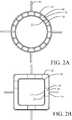
- FIG. 2Ais a front section view of the implementation of FIG. 1A ;
- FIG. 2Bis a front section view of a structural alternative for the first implementation with a rectangular profile
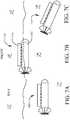
- FIG. 3is a schematic side cutaway view of the first implementation
- FIG. 4is a side view of the first implementation in a “pogo” orientation
- FIG. 5is a block diagram of an exemplary control system with navigation and sensing components
- FIG. 6is a schematic side cutaway view of the second implementation
- FIGS. 7A, 7B and 7Care pictorial representations of the operational sequence for the second implementation
- FIG. 8Ais a side view of a structural alternative for the second implementation
- FIG. 8Bis a schematic side cutaway view of the alternative for the second implementation.
- FIG. 9is a flow chart showing a first method for electrical power generation for the first implementation.
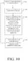
- FIG. 10is a flow chart showing a second method for electrical power generation for the second implementation.
- the exemplary implementations for a UUV as described hereinprovide an underwater energy harvesting drone (UEHD), more generally described as an energy harvesting underwater vehicle, having a submersible primary hull in thermal contact with a first operational interface on a plurality of thermoelectric modules and a thermal transfer element in contact with a second operational interface on the plurality of thermoelectric modules whereby positioning of the UEHD to create a thermal gradient between the primary hull and the thermal transfer element induces electrical power generation by the thermoelectric modules.
- UEHDunderwater energy harvesting drone
- FIG. 1Ashows a first implementation of the UEHD 10 .
- the UEHD 10has a primary hull 12 and is maneuvered (e.g. navigated) through an ocean environment with a propulsor 13 (shown as a standard multi-bladed screw as exemplary) and control planes 14 (e.g. control fins or hydrodynamic control surfaces) pivotally connected to the primary hull 12 for directional control of the UEHD 10 .
- a propulsor 13shown as a standard multi-bladed screw as exemplary
- control planes 14e.g. control fins or hydrodynamic control surfaces
- FIG. 2Aan internal storage tank 16 , which is fillable with cold ocean water as will be described subsequently, is employed as a thermal transfer element.
- the internal storage tank 16is substantially concentric within the primary hull 12 for the implementation shown and a plurality of thermoelectric modules 18 are mounted between the internal storage tank 16 and the primary hull 12 with a first operational surface 20 on each thermoelectric module 18 in thermal contact with the primary hull 12 and a second operational surface 22 in thermal contact with the internal storage tank 16 .
- the thermoelectric modulesmay be selected from at least one of a Peltier junction device (Seebeck, Thompson effects) and a Sterling engine. A temperature differential between the primary hull 12 and the internal storage tank 16 will provide a thermal gradient for operation of the thermoelectric modules 18 .
- the UEHD of FIG. 2Ais substantially circular in the central cross section shown.
- An exemplary alternative implementationis shown in FIG. 2B wherein the central cross section is rectangular in shape with both the primary hull 12 ′ and internal storage tank 16 ′ having a rectangular cross section.
- the thermoelectric modules 18are mounted intermediate the flat sides 17 of the storage tank 16 ′ and the flat inner sides 19 of the primary hull 12 ′ to achieve the desired thermal gradient.
- the primary hull 12houses an electrical motor 24 for the propulsor 13 and a control system 26 for operation and navigation of the UEHD 10 .
- control system 26operates both the propulsor 13 and one or more of the control planes 14 to propel and navigate UEHD 10 through water.
- An electrical power storage device 28which may be a rechargeable battery including a single battery element, a bank of storage batteries such as Lithium Ion, Lithium Ion Polymer, Nickel Cadmium, Nickel Metal Hydride, Lead Acid, or a capacitive storage system such as a nano-technology supercapacitor, is connected through a voltage transformer circuit 30 to the thermoelectric modules 18 and the motor 24 . Electrical power for the control system 26 may also be provided from the electrical power storage device 28 .
- the exemplary implementation shown in FIG. 3has an inlet scoop 32 and a vent 34 connecting the internal storage tank 16 with ocean water on the exterior of the primary hull 12 .
- the inlet scoop 32 and the vent 34may be retractable or incorporate door closures for open and closed positions to allow selective fluid communication with the external ocean water.
- a pump 36 powered by the electrical power storage device 28may be employed to pump water into the internal storage tank 16 from the inlet scoop 32 and out the vent 34 to exchange the water in the internal storage tank.
- the inlet scoop 32 and vent 34may be opened to the external ocean water with the UEHD 10 underway allowing dynamic pressure of the water to create the flow through the internal storage tank 16 . With the inlet scoop 32 and vent 34 in the closed position cold ocean water entrained into the internal storage tank 16 is stored.
- the UEHD 10is navigated either autonomously or remotely by the control system 26 pursuant to a navigational profile (included as a portion of the mission/operation profile) to locations of hydrothermal vents near the ocean floor.
- a navigational profileincluded as a portion of the mission/operation profile
- hydrothermal ventsnear the ocean floor.
- a global distribution of hydrothermal vent fieldsis present throughout the world's oceans.
- Such thermal ventsproduce hot water plumes ranging in temperature from 60° to 646° C.
- the UEHD 10is then navigated by the control system 26 to locate the primary hull 12 in a hydrothermal vent and either loiters in the hot plume of the vent or tracks the vent plume current to remain with the primary hull 12 positioned in a “hot zone” compared to surrounding ocean water and the initial temperature of the water stored in the internal storage tank 16 .
- the temperature differential of the hot plume in convective and conductive contact with the primary hull 12 and the cold water stored with the internal storage tank 16 acting as a thermal capacitorprovides a thermal gradient for operation of the thermoelectric modules 18 which generate power to charge the electrical power storage device 28 .
- thermoelectric modulesOperation of the thermoelectric modules will create warming of the water in the internal storage tank 16 .
- the UEHD 10is maneuvered by the control system 26 into open water and the internal storage tank 16 is exhausted and refilled by operation of the inlet scoop 32 and vent 34 .
- the UEHD 10may then be repositioned within the vent plume or moved to a different vent plume as necessary for recharging of the electrical power storage device 28 .
- the UEHD 10may be operated by the control system 26 on its intended mission profile.
- the thermal gradientmay be reversed by navigating the UEHD 10 into the plume of the thermal vent and opening the inlet scoop 32 and vent 34 to entrain hot water from the plume.
- the UEHD 10is then navigated by the control system 26 into open cold ocean water and the temperature differential of the cold ocean water in convective and conductive contact with the primary hull 12 and the hot water from the plume stored with the internal storage tank 16 acting as a thermal capacitor provides a reversed thermal gradient for operation of the thermoelectric modules 18 which generate power to charge the electrical power storage device 28 .
- Voltage transformer circuit 30may be adapted to sense reversed current produced by the thermoelectric modules based on the reversed thermal gradient and provide rectification for charging of the electric power storage device 28 .
- thermoelectric moduleswill create cooling of the water in the internal storage tank 16 .
- the UEHD 10is maneuvered by the control system 26 back to a thermal vent and the internal storage tank 16 is exhausted and refilled by operation of the inlet scoop 32 and vent 34 .
- the systems provided in the UEHD 10allows “surfing” between hydrothermal vents to provide recharging of the electrical power storage device 28 for substantially uninterrupted operation in the mission profile.
- the mission (e.g. operation) profilecan include activities such as exploration, environmental monitoring and security operations.
- an orienting ballast tank 38may be employed with appropriate control valves 40 and a pump or other venting system (including in an exemplary implementation use of the pump 36 ) to alter ballast of the UEHD 10 to selectively induce a vertical, or “pogo” orientation as shown in FIG. 4 .
- the UEHD 10may be maneuvered into the hydrothermal vent plume 42 and reoriented to the pogo position by filling the ballast tank 38 to provide greater exposure of the primary hull 12 to the vent plume if the internal storage tank 16 has been filled cold ocean water.
- thermoelectric charging cycleUpon completion of the thermoelectric charging cycle or depletion of the temperature differential in the internal storage tank 16 , water is expelled from the ballast tank 38 and the UEHD 10 is reoriented to its conventional operating orientation to provide normal cruising capability.
- the pogo orientationmay also be employed to assist in filling the internal storage tank 16 with water from the plume if a negative temperature differential between the primary hull 12 and internal storage tank 16 is employed for the charging cycle.
- the control system 26incorporates a navigation system 502 that may be preloaded with a specific mission (e.g. operation) profile 503 for autonomous operation using input from a Global Positioning System (GPS) 504 or GPS sensors, inertial navigation (e.g. guidance) systems 506 or comparable navigation elements, or may be controlled remotely with a communications module 508 and a remote control system 509 .
- Artificial intelligence (AI)may be incorporated in a control processor 510 for maneuvering or loitering within specified parameters in the mission profile.
- Control signals for physical control of the UEHD 10 by the control system 26are provided through a motor controller 512 connected to the motor 24 and control planes actuation system 514 connected to the control planes 14 .
- FIG. 1Bdemonstrates a second implementation of an UEHD 110 .
- the UEHD 110has a primary hull 112 and is maneuvered through an ocean environment with a propulsor 113 (shown as a standard multi-bladed screw as exemplary) and control planes 114 .
- the thermal transfer element of the second implementationis a heat dissipater 116 mounted to and extending from a top surface 117 of the primary hull 112 .
- the heat dissipater 116may be telescopically extendible for increased surface area.
- the primary hull 112houses a motor 124 for the propulsor 113 and a control system 126 for operation of the UEHD 110 .
- An electrical power storage device 128which may be a single battery element, a bank of storage batteries such as Lithium Ion, Lithium Ion Polymer, Nickel Cadmium, Nickel Metal Hydride, Lead Acid, or a capacitive storage system such as a nano-technology supercapacitor, is connected through a voltage transformer circuit 130 to the thermoelectric modules 118 and the motor 124 . Electrical power for the control system 126 may also be provided from the electrical power storage device 128 .
- Thermoelectric modules 118are connected with a first operational surface 120 on each thermoelectric module 118 in thermal contact with the primary hull 112 and a second operational surface 122 in thermal contact with the heat dissipater 116 .
- UEHD 110cruises in a submerged condition as shown in FIG. 7A pursuant to a mission profile established by the control system 126 .
- Anticipated operation for the second implementationoccurs in artic waters where ocean water temperature is relative constant, at least ⁇ 2° C. or warmer while air temperatures, particularly at night, are significantly colder (approximately ⁇ 20° C. but ranging from about ⁇ 60° to ⁇ 10° C.).
- control system 126causes the UEHD 110 to surface as shown in FIG. 7B selectively exposing the heat dissipater 116 from the ocean water to the air.
- thermoelectric modules 118Temperature differential between the primary hull 112 immersed in ocean water 140 and the heat dissipater 116 in convective contact with surrounding air 142 is significant and sufficient for operation of the thermoelectric modules 118 to provide electrical energy generation for charging of the electrical power storage device.
- the control system 126Upon completion of charging or as otherwise operationally desirable, the control system 126 causes the UEHD 110 to submerge for continuing operation as seen in FIG. 7C .
- ballast tanks and associated operational systems for providing depth control of the disclosed implementations of the UEHD for diving, surfacing and desired operational depthare well known in the art and not described herein.
- FIGS. 8A and 8BAn alternative structural arrangement for the second implementation is shown in FIGS. 8A and 8B .
- UEHD 210incorporates a primary hull 212 which has an upper portion 212 a and a lower portion 212 b separated by an insulating barrier 213 . While the hull portions 212 a , 212 b are shown as symmetrical above and below the insulating barrier 213 non-symmetrical arrangements may be employed.
- thermoelectric modules 218are engaged with a first operational surface 220 on each thermoelectric module 218 in thermal contact the upper portion 212 a and a second operational surface 222 in thermal contact with the lower portion 212 b .
- a transfer plate 214 or other thermally conductive elementmay be employed for effective contact between the second operational surface 222 and the lower portion 212 b or conversely between the first operational surface 220 and the upper portion 212 a .
- UEHD 210incorporates a power storage device 228 , voltage transformer circuit 230 , motor 224 and control system 226 .
- the UEHD 210operates in a manner similar to the UEHD 110 , surfacing to expose the upper portion 212 a of the primary hull 212 to the air is a heat dissipater.
- the UEHD 110 , 210 thermal transfer through the thermoelectric modules 118 , 218may be reversed if the air temperature is warmer than the water temperature thereby providing a reverse thermal gradient.
- a reverse temperature gradientoccurs the electrical current generated by the thermoelectric modules 118 , 218 reverses direction.
- a diode circuit within the voltage transformer circuit 130 , 230is used to capture the reversed current and then store the charge in the electrical power storage device 128 , 228 .
- the implementations of the UEHD as disclosedprovide methods for operation of a UUV. As shown in FIG. 9 (with reference to FIGS. 1A and 3 ), the UEHD 10 is navigated either autonomously or remotely by the control system 26 between locations of hydrothermal vents near the ocean floor, step 902 .
- step 904the inlet scoop 32 and vent 34 are deployed or placed in an open position and cold ocean water is entrained by pumping or dynamic pressure into the internal storage tank 16 in a first position, step 904 , and the inlet scoop 32 and vent 34 are then closed, step 906 , placing the internal storage tank 16 in a second position to store the cold ocean water.
- the UEHD 10is navigated by the control system 26 to a hydrothermal vent location and either loiters with the primary hull 12 in the hot plume of the vent or tracks the vent plume current to remain with the primary hull 12 in a “hot zone” compared to surrounding ocean water and the initial temperature of the water in the internal storage tank 16 , step 908 .
- the orienting ballast tank 38may be filled, step 910 , orienting the UEHD 10 in a pogo position. In this manner, orienting ballast tank 38 is filled for orienting the UEHD in the pogo position.
- the UEHD 10is maneuvered by the control system 26 into open water, step 914 , and the internal storage tank 16 is exhausted and refilled by operation of the inlet scoop 32 and vent 34 , step 904 , to repeat the process of the first sequence.
- the orienting ballast tank 38may be filled, step 911 , orienting the UEHD 10 in a pogo position.
- the inlet scoop 32 and vent 34are deployed or opened and hot water from the plume is entrained by pumping or dynamic pressure into the internal storage tank 16 in the first position, step 905 , and the inlet scoop 32 and vent 34 are then closed, step 907 , placing the internal storage tank 16 in a second position (e.g. rotated relative to the pogo position) to store the hot water.
- the UEHD 10is navigated by the control system 26 out of the vent plume and into the open ocean where cold water provides a negative temperature differential with respect to the initial temperature of the hot water in the internal storage tank 16 , step 909 .
- the temperature differential of the cold open ocean water in convective and conductive contact with the primary hull 12 and the hot water stored with the internal storage tank 16 acting as a thermal capacitor,provides the thermal gradient and the thermoelectric modules 18 are operated based on the thermal gradient between the primary hull and internal storage tank to generate power to charge the electrical power storage device 28 , step 913 .
- the UEHD 10is maneuvered by the control system 26 back to a hydrothermal vent plume, step 915 , and the internal storage tank 16 is exhausted and refilled by operation of the inlet scoop 32 and vent 34 , step 905 , to repeat the process of the second sequence.
- the UEHDmay then be operated in the desired mission profile, step 916 , in concert with navigating and operating the thermoelectric modules ( 18 , 118 , 218 ) to charge the electrical power storage devices ( 28 , 128 , 228 ).
- the UEHD 10may be repositioned within the vent plume or moved to a different vent plume as necessary for recharging of the electrical power storage device 28 beginning with step 904 , 905 .
- the UEHD 110 , 210is operated submerged on a mission profile directed by the control system 126 , step 1002 .
- control system 126causes the UEHD 110 , 210 to surface, step 1004 , exposing the heat dissipater 116 , 212 a to the air.
- thermoelectric modules 118are operated to provide electrical energy generation for charging of the electrical power storage device employing temperature differential between the primary hull 112 (or 212 b ) immersed in the ocean water 140 and the heat dissipater 116 , 212 a in convective contact with the surrounding air 142 , step 1006 .
- the control system 126causes the UEHD 110 to submerge for continuing operation, step 1008 .
Landscapes
- Engineering & Computer Science (AREA)
- Mechanical Engineering (AREA)
- Aviation & Aerospace Engineering (AREA)
- Power Engineering (AREA)
- Ocean & Marine Engineering (AREA)
- Charge And Discharge Circuits For Batteries Or The Like (AREA)
- Other Liquid Machine Or Engine Such As Wave Power Use (AREA)
Abstract
Description
Claims (20)
Priority Applications (7)
| Application Number | Priority Date | Filing Date | Title |
|---|---|---|---|
| US15/894,613US11152555B2 (en) | 2018-02-12 | 2018-02-12 | Underwater energy harvesting drone and method for operation |
| RU2018140081ARU2018140081A (en) | 2018-02-12 | 2018-11-14 | UNMANNED UNDERWATER UNIT WITH ENERGY GATHERING AND METHOD OF CONTROL ITS OPERATION |
| EP18207066.4AEP3524507B1 (en) | 2018-02-12 | 2018-11-19 | Underwater energy harvesting drone and method for operation |
| JP2018217215AJP7305336B2 (en) | 2018-02-12 | 2018-11-20 | Underwater energy harvesting drone and operation method |
| KR1020190003362AKR102605462B1 (en) | 2018-02-12 | 2019-01-10 | Underwater energy harvesting drone and method for operation |
| CA3029964ACA3029964C (en) | 2018-02-12 | 2019-01-14 | Underwater energy harvesting drone and method for operation |
| CN201910110394.9ACN110165940B (en) | 2018-02-12 | 2019-02-11 | Underwater energy harvesting drone and method of operation |
Applications Claiming Priority (1)
| Application Number | Priority Date | Filing Date | Title |
|---|---|---|---|
| US15/894,613US11152555B2 (en) | 2018-02-12 | 2018-02-12 | Underwater energy harvesting drone and method for operation |
Publications (2)
| Publication Number | Publication Date |
|---|---|
| US20190252592A1 US20190252592A1 (en) | 2019-08-15 |
| US11152555B2true US11152555B2 (en) | 2021-10-19 |
Family
ID=64402008
Family Applications (1)
| Application Number | Title | Priority Date | Filing Date |
|---|---|---|---|
| US15/894,613Active2038-04-02US11152555B2 (en) | 2018-02-12 | 2018-02-12 | Underwater energy harvesting drone and method for operation |
Country Status (7)
| Country | Link |
|---|---|
| US (1) | US11152555B2 (en) |
| EP (1) | EP3524507B1 (en) |
| JP (1) | JP7305336B2 (en) |
| KR (1) | KR102605462B1 (en) |
| CN (1) | CN110165940B (en) |
| CA (1) | CA3029964C (en) |
| RU (1) | RU2018140081A (en) |
Cited By (11)
| Publication number | Priority date | Publication date | Assignee | Title |
|---|---|---|---|---|
| US20220315183A1 (en)* | 2021-03-31 | 2022-10-06 | Mitsubishi Heavy Industries, Ltd. | Fluid machine and underwater vehicle |
| US11975584B2 (en) | 2018-11-21 | 2024-05-07 | Polaris Industries Inc. | Vehicle having adjustable compression and rebound damping |
| US12221195B2 (en) | 2021-03-31 | 2025-02-11 | Mitsubishi Heavy Industries, Ltd. | Fluid machine and underwater vehicle |
| US12275509B2 (en) | 2021-03-31 | 2025-04-15 | Mitsubishi Heavy Industries, Ltd. | Fluid machine and underwater vehicle |
| US12286202B2 (en) | 2021-03-31 | 2025-04-29 | Mitsubishi Heavy Industries, Ltd. | Fluid machine and underwater vehicle |
| US12291069B2 (en) | 2012-11-07 | 2025-05-06 | Polaris Industries Inc. | Vehicle having suspension with continuous damping control |
| US12325432B2 (en) | 2014-10-31 | 2025-06-10 | Polaris Industries Inc. | System and method for controlling a vehicle |
| US12330467B2 (en) | 2017-06-09 | 2025-06-17 | Polaris Industries Inc. | Adjustable vehicle suspension system |
| US12337824B2 (en) | 2016-11-18 | 2025-06-24 | Polaris Industries Inc. | Vehicle having adjustable suspension |
| US12391116B2 (en) | 2010-06-03 | 2025-08-19 | Polaris Industries Inc. | Adjustable performance for a vehicle |
| US12397878B2 (en) | 2020-05-20 | 2025-08-26 | Polaris Industries Inc. | Systems and methods of adjustable suspensions for off-road recreational vehicles |
Families Citing this family (8)
| Publication number | Priority date | Publication date | Assignee | Title |
|---|---|---|---|---|
| US10900702B2 (en)* | 2018-06-08 | 2021-01-26 | International Business Machines Corporation | Automated storage warehouse |
| CN110920818B (en)* | 2019-11-01 | 2020-11-17 | 浙江大学 | Section motion platform based on ocean temperature difference energy driving and lifting control method thereof |
| CN111186543B (en)* | 2020-01-19 | 2021-01-01 | 潍坊学院 | Underwater robot system based on 5G communication |
| CN111332435B (en)* | 2020-03-09 | 2021-01-29 | 中国船舶科学研究中心(中国船舶重工集团公司第七0二研究所) | AUV modularization carrier structure |
| CN111319760B (en)* | 2020-03-26 | 2024-05-28 | 合肥工业大学 | Water-air dual-purpose unmanned aerial vehicle |
| US20230303224A1 (en)* | 2020-08-17 | 2023-09-28 | Quantum Industrial Development Corp. | Long endurance small displacement maritime submersible propulsion system |
| US12030676B1 (en)* | 2021-04-22 | 2024-07-09 | Hrl Laboratories, Llc | Hydride forming of sheet materials |
| KR102771231B1 (en)* | 2024-02-20 | 2025-02-26 | 주식회사 우성조선 | Self-powered buoy |
Citations (8)
| Publication number | Priority date | Publication date | Assignee | Title |
|---|---|---|---|---|
| US6914343B2 (en) | 2001-12-12 | 2005-07-05 | Hi-Z Technology, Inc. | Thermoelectric power from environmental temperature cycles |
| US7012554B2 (en) | 2001-12-12 | 2006-03-14 | Hi-Z Technology, Inc. | Thermoelectric vehicle tracking device |
| US7262360B1 (en)* | 2003-08-18 | 2007-08-28 | United States Of America As Represented By The Secretary Of The Navy | Underwater power generation using underwater thermocline |
| US20080264323A1 (en) | 2005-10-19 | 2008-10-30 | Go Science Limited | Submersible Vehicle |
| US7649138B2 (en) | 2005-05-25 | 2010-01-19 | Hi-Z Technology, Inc. | Thermoelectric device with surface conforming heat conductor |
| US20110179988A1 (en)* | 2009-03-07 | 2011-07-28 | Lockheed Martin Corporation | Underwater Vehicle |
| KR20120114454A (en) | 2011-04-07 | 2012-10-17 | 최광식 | An electric power generation system on the water that has thermopower module and peripheral apparatus that uses the water flow for heatsink to maximize the efficiency |
| US9382902B1 (en) | 2012-04-25 | 2016-07-05 | The Boeing Company | Undersea energy harvesting electrical power station |
Family Cites Families (4)
| Publication number | Priority date | Publication date | Assignee | Title |
|---|---|---|---|---|
| JPS6042694A (en)* | 1983-08-19 | 1985-03-06 | 川崎重工業株式会社 | Power device for underwater travelling body |
| JP6583905B2 (en)* | 2014-12-11 | 2019-10-02 | 学校法人 東洋大学 | Thermoelectric element driving device |
| US20170005250A1 (en)* | 2015-06-30 | 2017-01-05 | The Boeing Company | Powering aircraft sensors using thermal capacitors |
| CN106452190A (en)* | 2016-12-06 | 2017-02-22 | 电子科技大学 | Subsea power generation system utilizing energy of subsea heat liquid |
- 2018
- 2018-02-12USUS15/894,613patent/US11152555B2/enactiveActive
- 2018-11-14RURU2018140081Apatent/RU2018140081A/enunknown
- 2018-11-19EPEP18207066.4Apatent/EP3524507B1/enactiveActive
- 2018-11-20JPJP2018217215Apatent/JP7305336B2/enactiveActive
- 2019
- 2019-01-10KRKR1020190003362Apatent/KR102605462B1/enactiveActive
- 2019-01-14CACA3029964Apatent/CA3029964C/enactiveActive
- 2019-02-11CNCN201910110394.9Apatent/CN110165940B/enactiveActive
Patent Citations (8)
| Publication number | Priority date | Publication date | Assignee | Title |
|---|---|---|---|---|
| US6914343B2 (en) | 2001-12-12 | 2005-07-05 | Hi-Z Technology, Inc. | Thermoelectric power from environmental temperature cycles |
| US7012554B2 (en) | 2001-12-12 | 2006-03-14 | Hi-Z Technology, Inc. | Thermoelectric vehicle tracking device |
| US7262360B1 (en)* | 2003-08-18 | 2007-08-28 | United States Of America As Represented By The Secretary Of The Navy | Underwater power generation using underwater thermocline |
| US7649138B2 (en) | 2005-05-25 | 2010-01-19 | Hi-Z Technology, Inc. | Thermoelectric device with surface conforming heat conductor |
| US20080264323A1 (en) | 2005-10-19 | 2008-10-30 | Go Science Limited | Submersible Vehicle |
| US20110179988A1 (en)* | 2009-03-07 | 2011-07-28 | Lockheed Martin Corporation | Underwater Vehicle |
| KR20120114454A (en) | 2011-04-07 | 2012-10-17 | 최광식 | An electric power generation system on the water that has thermopower module and peripheral apparatus that uses the water flow for heatsink to maximize the efficiency |
| US9382902B1 (en) | 2012-04-25 | 2016-07-05 | The Boeing Company | Undersea energy harvesting electrical power station |
Non-Patent Citations (4)
| Title |
|---|
| Bradley, A. and Feezor, M, Power Systems for Autonomous Underwater Vehicles, IEEE JOurnal of Oceanic Enbineering, vol. 26, No. 4, Oct. 2001. |
| Chirgwin, R, US Navy develops underwater wireless battery-charging tech, The Register, Aug. 29, 2017 available at https://www.theregister.co.uk/2017/08/29/us_navy_develops_underwater_wireless_batterycharging _tech/. |
| Webb, D. C., et. al., SLOCUM: An Underwater Glider Propelled by Environmental Energy, IEEE J. of Oceanic Engineering, vol. 26, No. 4, pp. 447-452, Oct. 2001. |
| Yuan, C., et. al., Marine Environmental Damage Effects of Solar Cell Panel, IEEE, Prognostics & System Health Management Conference, 2010. |
Cited By (13)
| Publication number | Priority date | Publication date | Assignee | Title |
|---|---|---|---|---|
| US12391116B2 (en) | 2010-06-03 | 2025-08-19 | Polaris Industries Inc. | Adjustable performance for a vehicle |
| US12291069B2 (en) | 2012-11-07 | 2025-05-06 | Polaris Industries Inc. | Vehicle having suspension with continuous damping control |
| US12325432B2 (en) | 2014-10-31 | 2025-06-10 | Polaris Industries Inc. | System and method for controlling a vehicle |
| US12337824B2 (en) | 2016-11-18 | 2025-06-24 | Polaris Industries Inc. | Vehicle having adjustable suspension |
| US12330467B2 (en) | 2017-06-09 | 2025-06-17 | Polaris Industries Inc. | Adjustable vehicle suspension system |
| US12384214B2 (en) | 2018-11-21 | 2025-08-12 | Polaris Industries Inc. | Vehicle having adjustable compression and rebound damping |
| US11975584B2 (en) | 2018-11-21 | 2024-05-07 | Polaris Industries Inc. | Vehicle having adjustable compression and rebound damping |
| US12397878B2 (en) | 2020-05-20 | 2025-08-26 | Polaris Industries Inc. | Systems and methods of adjustable suspensions for off-road recreational vehicles |
| US12286202B2 (en) | 2021-03-31 | 2025-04-29 | Mitsubishi Heavy Industries, Ltd. | Fluid machine and underwater vehicle |
| US12286201B2 (en)* | 2021-03-31 | 2025-04-29 | Mitsubishi Heavy Industries, Ltd. | Fluid machine for underwater vehicle and underwater vehicle |
| US12275509B2 (en) | 2021-03-31 | 2025-04-15 | Mitsubishi Heavy Industries, Ltd. | Fluid machine and underwater vehicle |
| US12221195B2 (en) | 2021-03-31 | 2025-02-11 | Mitsubishi Heavy Industries, Ltd. | Fluid machine and underwater vehicle |
| US20220315183A1 (en)* | 2021-03-31 | 2022-10-06 | Mitsubishi Heavy Industries, Ltd. | Fluid machine and underwater vehicle |
Also Published As
| Publication number | Publication date |
|---|---|
| KR20190098044A (en) | 2019-08-21 |
| CA3029964C (en) | 2023-05-16 |
| CN110165940A (en) | 2019-08-23 |
| US20190252592A1 (en) | 2019-08-15 |
| KR102605462B1 (en) | 2023-11-22 |
| JP7305336B2 (en) | 2023-07-10 |
| EP3524507A1 (en) | 2019-08-14 |
| CA3029964A1 (en) | 2019-08-12 |
| CN110165940B (en) | 2024-12-13 |
| EP3524507B1 (en) | 2021-09-01 |
| RU2018140081A3 (en) | 2022-04-07 |
| JP2019137386A (en) | 2019-08-22 |
| RU2018140081A (en) | 2020-05-14 |
Similar Documents
| Publication | Publication Date | Title |
|---|---|---|
| US11152555B2 (en) | Underwater energy harvesting drone and method for operation | |
| US10589829B2 (en) | Gliding robotic fish navigation and propulsion | |
| Wang et al. | Reviews of power systems and environmental energy conversion for unmanned underwater vehicles | |
| JP7535510B2 (en) | Systems and methods for retractable marine power generation | |
| US20120312221A1 (en) | Submersible vehicles and methods for propelling and/or powering the same in an underwater environment | |
| Kunz et al. | Toward extraplanetary under‐ice exploration: Robotic steps in the Arctic | |
| US10322782B1 (en) | Combined autonomous underwater vehicle and buoy device | |
| US8065972B2 (en) | Underwater vehicle | |
| Pyle et al. | Leveraging a large UUV platform with a docking station to enable forward basing and persistence for light weight AUVs | |
| Jung et al. | A study on unmanned surface vehicle combined with remotely operated vehicle system | |
| Hildebrandt et al. | Design of an autonomous under-ice exploration system | |
| US20240116605A1 (en) | nautical Ground Station | |
| CN110429865A (en) | Underwater robot thermal gradient energy charging unit | |
| CN110641637A (en) | A track-controllable ocean observation platform based on thermoelectric power generation | |
| Sollesnes et al. | Towards autonomous ocean observing systems using Miniature Underwater Gliders with UAV deployment and recovery capabilities | |
| CN112498144A (en) | Solar driven anchor system type autonomous aircraft multifunctional docking station and docking method | |
| US11001357B2 (en) | Tactical maneuvering ocean thermal energy conversion buoy for ocean activity surveillance | |
| US10472033B2 (en) | Systems and methods for power generation based on surface air-to-water thermal differences | |
| Bykanova et al. | The compact remotely operated underwater vehicle with the variable restoring moment | |
| Zeng et al. | The observation of sea-ice in the six Chinese national arctic expedition using polar-ARV | |
| Alvarez et al. | Folaga: a very low cost autonomous underwater vehicle for coastal oceanography | |
| US11462939B1 (en) | Hydrothermal vent energy harvesting, storage, and power distribution system | |
| Berkenpas et al. | The Driftcam: A buoyancy controlled pelagic camera trap | |
| Page | Design of a mobile underwater charging system | |
| Sze et al. | Low Cost Structural Morphing AUV for Long-term Water Column Exploration and Data-harvesting |
Legal Events
| Date | Code | Title | Description |
|---|---|---|---|
| AS | Assignment | Owner name:THE BOEING COMPANY, ILLINOIS Free format text:ASSIGNMENT OF ASSIGNORS INTEREST;ASSIGNOR:HILLER, NATHAN D.;REEL/FRAME:045309/0797 Effective date:20180212 | |
| FEPP | Fee payment procedure | Free format text:ENTITY STATUS SET TO UNDISCOUNTED (ORIGINAL EVENT CODE: BIG.); ENTITY STATUS OF PATENT OWNER: LARGE ENTITY | |
| STPP | Information on status: patent application and granting procedure in general | Free format text:RESPONSE TO NON-FINAL OFFICE ACTION ENTERED AND FORWARDED TO EXAMINER | |
| STPP | Information on status: patent application and granting procedure in general | Free format text:NON FINAL ACTION MAILED | |
| STPP | Information on status: patent application and granting procedure in general | Free format text:NON FINAL ACTION MAILED | |
| STPP | Information on status: patent application and granting procedure in general | Free format text:NON FINAL ACTION MAILED | |
| STPP | Information on status: patent application and granting procedure in general | Free format text:RESPONSE TO NON-FINAL OFFICE ACTION ENTERED AND FORWARDED TO EXAMINER | |
| STPP | Information on status: patent application and granting procedure in general | Free format text:NOTICE OF ALLOWANCE MAILED -- APPLICATION RECEIVED IN OFFICE OF PUBLICATIONS | |
| STPP | Information on status: patent application and granting procedure in general | Free format text:PUBLICATIONS -- ISSUE FEE PAYMENT RECEIVED | |
| STPP | Information on status: patent application and granting procedure in general | Free format text:PUBLICATIONS -- ISSUE FEE PAYMENT VERIFIED | |
| STCF | Information on status: patent grant | Free format text:PATENTED CASE | |
| MAFP | Maintenance fee payment | Free format text:PAYMENT OF MAINTENANCE FEE, 4TH YEAR, LARGE ENTITY (ORIGINAL EVENT CODE: M1551); ENTITY STATUS OF PATENT OWNER: LARGE ENTITY Year of fee payment:4 |