US11150622B2 - Quality control isometric for inspection of field welds and flange bolt-up connections - Google Patents
Quality control isometric for inspection of field welds and flange bolt-up connectionsDownload PDFInfo
- Publication number
- US11150622B2 US11150622B2US16/193,927US201816193927AUS11150622B2US 11150622 B2US11150622 B2US 11150622B2US 201816193927 AUS201816193927 AUS 201816193927AUS 11150622 B2US11150622 B2US 11150622B2
- Authority
- US
- United States
- Prior art keywords
- isometric
- fabrication
- flange bolt
- field
- construction project
- Prior art date
- Legal status (The legal status is an assumption and is not a legal conclusion. Google has not performed a legal analysis and makes no representation as to the accuracy of the status listed.)
- Active, expires
Links
Images


Classifications
- G—PHYSICS
- G05—CONTROLLING; REGULATING
- G05B—CONTROL OR REGULATING SYSTEMS IN GENERAL; FUNCTIONAL ELEMENTS OF SUCH SYSTEMS; MONITORING OR TESTING ARRANGEMENTS FOR SUCH SYSTEMS OR ELEMENTS
- G05B19/00—Programme-control systems
- G05B19/02—Programme-control systems electric
- G05B19/418—Total factory control, i.e. centrally controlling a plurality of machines, e.g. direct or distributed numerical control [DNC], flexible manufacturing systems [FMS], integrated manufacturing systems [IMS] or computer integrated manufacturing [CIM]
- G05B19/41875—Total factory control, i.e. centrally controlling a plurality of machines, e.g. direct or distributed numerical control [DNC], flexible manufacturing systems [FMS], integrated manufacturing systems [IMS] or computer integrated manufacturing [CIM] characterised by quality surveillance of production
- G—PHYSICS
- G05—CONTROLLING; REGULATING
- G05B—CONTROL OR REGULATING SYSTEMS IN GENERAL; FUNCTIONAL ELEMENTS OF SUCH SYSTEMS; MONITORING OR TESTING ARRANGEMENTS FOR SUCH SYSTEMS OR ELEMENTS
- G05B19/00—Programme-control systems
- G05B19/02—Programme-control systems electric
- G05B19/04—Programme control other than numerical control, i.e. in sequence controllers or logic controllers
- G05B19/042—Programme control other than numerical control, i.e. in sequence controllers or logic controllers using digital processors
- G05B19/0428—Safety, monitoring
- G—PHYSICS
- G05—CONTROLLING; REGULATING
- G05B—CONTROL OR REGULATING SYSTEMS IN GENERAL; FUNCTIONAL ELEMENTS OF SUCH SYSTEMS; MONITORING OR TESTING ARRANGEMENTS FOR SUCH SYSTEMS OR ELEMENTS
- G05B19/00—Programme-control systems
- G05B19/02—Programme-control systems electric
- G05B19/18—Numerical control [NC], i.e. automatically operating machines, in particular machine tools, e.g. in a manufacturing environment, so as to execute positioning, movement or co-ordinated operations by means of programme data in numerical form
- G05B19/406—Numerical control [NC], i.e. automatically operating machines, in particular machine tools, e.g. in a manufacturing environment, so as to execute positioning, movement or co-ordinated operations by means of programme data in numerical form characterised by monitoring or safety
- G—PHYSICS
- G05—CONTROLLING; REGULATING
- G05B—CONTROL OR REGULATING SYSTEMS IN GENERAL; FUNCTIONAL ELEMENTS OF SUCH SYSTEMS; MONITORING OR TESTING ARRANGEMENTS FOR SUCH SYSTEMS OR ELEMENTS
- G05B2219/00—Program-control systems
- G05B2219/30—Nc systems
- G05B2219/32—Operator till task planning
- G05B2219/32368—Quality control
- G—PHYSICS
- G05—CONTROLLING; REGULATING
- G05B—CONTROL OR REGULATING SYSTEMS IN GENERAL; FUNCTIONAL ELEMENTS OF SUCH SYSTEMS; MONITORING OR TESTING ARRANGEMENTS FOR SUCH SYSTEMS OR ELEMENTS
- G05B2219/00—Program-control systems
- G05B2219/30—Nc systems
- G05B2219/45—Nc applications
- G05B2219/45135—Welding
- Y—GENERAL TAGGING OF NEW TECHNOLOGICAL DEVELOPMENTS; GENERAL TAGGING OF CROSS-SECTIONAL TECHNOLOGIES SPANNING OVER SEVERAL SECTIONS OF THE IPC; TECHNICAL SUBJECTS COVERED BY FORMER USPC CROSS-REFERENCE ART COLLECTIONS [XRACs] AND DIGESTS
- Y02—TECHNOLOGIES OR APPLICATIONS FOR MITIGATION OR ADAPTATION AGAINST CLIMATE CHANGE
- Y02P—CLIMATE CHANGE MITIGATION TECHNOLOGIES IN THE PRODUCTION OR PROCESSING OF GOODS
- Y02P90/00—Enabling technologies with a potential contribution to greenhouse gas [GHG] emissions mitigation
- Y02P90/02—Total factory control, e.g. smart factories, flexible manufacturing systems [FMS] or integrated manufacturing systems [IMS]
Definitions
- the present disclosurerelates to managing inspection of construction elements, and more specifically to techniques for managing inspection of field welds and flange bolt-up connections.
- a new type of software and process flow that uses a quality control (QC) drawing(e.g., a QC isometric drawing) is provided that can efficiently manage the inspection of construction elements, such as field welds or flange bolt-up connections.
- the QC drawingincludes automatically generated unique numbers associated with locations.
- the QC drawingmay be generated by the software from existing fabrication data (e.g., an issued-for-construction (IFC) fabrication isometric data file) and provided together with a fabrication drawing (e.g., an IFC fabrication isometric drawing) to field inspection workers.
- IFCissued-for-construction
- a fabrication drawinge.g., an IFC fabrication isometric drawing
- a field inspection workermay mark-up the QC drawing, the marked-up copy being retained in a document management system.
- Using the QC drawingmay save labor hours typically spent in manual labeling and data entry, and help minimize human error.
- one or more numbering processes executing on one or more electronic devicesautomatically generate at least one of: unique numbers for field welds or flange bolt-up connections, in an infrastructure construction project.
- a modeling processadds the unique numbers for field welds or flange bolt-up connections to a virtual construction model of the infrastructure construction project.
- a QC drawing generation processBased on the virtual construction model and a fabrication data file (e.g., an IFC fabrication isometric data file) that describes a portion of the infrastructure construction project, a QC drawing generation process generates a QC drawing (e.g., a QC isometric drawing) for the portion of the infrastructure construction project that includes balloons linked to locations of field welds or flange bolt-up connections, each balloon including the unique numbers of a coral responding field weld or flange bolt-up connection.
- a copy of the QC drawingis provided to a field inspection worker (e.g., as a printed drawing or model file).
- the QC drawingmay be paired with a fabrication drawing (e.g., an IFC fabrication isometric drawing).
- the field workerperforms inspections, and provides back a marked-up copy of the QC drawing that includes field inspection results (e.g., physical signatures/sign-offs or electronic signatures/sign offs) associated with the unique number of each field weld or flange bolt-up connection (e.g., in the balloons including the unique numbers).
- field inspection resultse.g., physical signatures/sign-offs or electronic signatures/sign offs
- the marked-up copymay be maintained in a document control system to provide a record of the inspection.
- FIG. 2is a block diagram showing details of interaction of the software to produce QC isometric drawings
- FIG. 3is an example IFC fabrication isometric drawing that may be represented by an IFC fabrication isometric drawing file
- FIG. 4is an example user interface showing status of the processing of selected IFC fabrication isometric data files by the isometric drawing software.
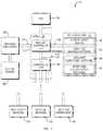
- FIG. 1is a block diagram of an example electronic device 100 , one or more of which may be used to produce QC isometric drawings that may be used to manage inspection of field welds and flange bolt-up connections in an infrastructure construction project (e.g., a pipeline construction project).
- the electronic devicemay represent a server, a desktop computer, a mobile device, or another type of electronic device.
- the example electronic deviceincludes a central processing unit (CPU) 110 that may be coupled to a chipset 120 by a front side bus 115 .
- the chipset 120includes a memory controller hub 125 that is responsible for communications with high-speed devices such as system memory 130 and a graphics subsystem (e.g., a graphics card) 140 .
- graphics subsysteme.g., a graphics card
- the chipset 120further includes an input/output controller hub 165 coupled to the memory controller hub by an internal bus 150 .
- the input/output controller hub 165may support a variety of types of peripheral buses for connecting to other system components.
- the system componentsmay include one or more 110 devices 170 , such as a keyboard, a mouse, touch sensor, a printer, etc., one or more persistent storage devices 175 , such as a hard disk drive, a solid-state drive, or another type of persistent data store, one or more network interfaces 180 , such as an Ethernet interface or a Wi-Fi adaptor, among other system components.
- the network interface(s) 180may allow communication with other electronic devices 100 over a computer network, such as the Internet (e.g., to enable various types distributed computing as discussed further below).
- the softwaremay include work packaging software 190 that maintains a virtual construction model of an infrastructure construction project and is capable of tracking, updating, and editing work packages related thereto with status updates from the field.
- the work packaging software 190may include a number of software processes, such as a unique field weld numbering process, a unique bolts up numbering process and a modeling process; and a number of files that may be associated with virtual construction model, including IFC fabrication isometric drawing files (e.g., portable document format (PDF) files) embodying drawings that show details of how to fabricate portions of the infrastructure construction project and IFC fabrication isometric data files that describes the fabrication of portions of the infrastructure construction project and are used to produce the IFC fabrication isometric drawings.
- IFC fabrication isometric drawing filese.g., portable document format (PDF) files
- PDFportable document format
- the work packaging software 190may be the ConstructSimTM Work Packager Sever available from Bentley Systems. However, it should be understood that the work packaging software 190 may take a number of different forms.
- the softwaremay further include isometric drawing software 192 that is capable of managing isometric drawings and generating printable and/or electronically publishable deliverables (e.g., PDF drawings or iModelTM files) using data from a variety of sources, including from the virtual construction model and IFC fabrication isometric drawing files.
- the isometric drawing software 192may include a number of software processes, one of which may be a QC isometric drawing generation process that is configured to generate QC isometric drawings that includes balloons linked to locations of field welds or flange bolt-up connections and including unique numbers, as discussed in more detail below.
- the isometric drawing software 192may be the OpenPLANTTM Isometrics Manager available from Bentley Systems. However, it should be understood that the isometric drawing software 192 may take a number of different forms.
- the softwaremay further include document formatting software 194 that is capable of editing (e.g., merging) printable drawings (e.g., PDF drawings), for example, merging a QC isometric drawing with the an IFC fabrication isometric drawing to create a printable two-sided or two-page drawing deliverable, as discussed in more detail below.
- document formatting software 194may be the Adobe Acrobat® software available from Adobe Systems. However, it should be understood that the document formatting software 194 may take a number of different forms.
- the softwaremay include review and collaboration software 196 that is capable of displaying an electronically published version of a QC isometric drawing (e.g., an iModelTM file) to the display screen 160 , providing an electronic deliverable.
- a QC isometric drawinge.g., an iModelTM file
- the review and collaboration software 196may be Bentley NavigatorTM software available from Bentley Systems. However, it should be understood that the review and collaboration software 196 may take a number of different forms.
- the software 190 - 196is shown resident together in system memory 130 in FIG. 1 for purposes of illustration, it should be understood that in a distributed implementation the software 190 - 196 may be executed on separate electronic devices.
- the work packaging software 190may be executed on a first electronic device (e.g., a server)
- the isometric drawing software 192 and document formatting software 194may be executed on a second electronic device (e.g., a desktop computer)
- the review and collaboration software 196may be executed on a third electronic device (e.g., a mobile device).
- FIG. 2is a block diagram 200 showing details of interaction of the software 190 - 196 to produce QC isometric drawings.
- the work packaging software 190includes a modeling process 205 that maintains a virtual construction model 210 of an infrastructure construction project (e.g., a pipeline), which is associated with IFC fabrication isometric data files 215 and IFC fabrication isometric drawing files 220 that describe and show details of how to fabricate portions of the infrastructure construction project.
- FIG. 3is an example IFC fabrication isometric drawing 300 that may be represented by an IFC fabrication isometric drawing file 220 .
- the IFC fabrication isometric drawing 300includes fabrication information, but not construction specific information (such as field weld or bolt-up numbering).
- a unique field weld numbering process 225automatically generates unique numbers for field welds used in the infrastructure construction project.
- a unique bolt-up numbering process 230automatically generates unique numbers for flange bolt-up connections of the infrastructure construction project.
- the unique numbers for field welds or flange bolt-up connectionsare unique identifiers that are maintained throughout the infrastructure construction project's lifecycle. Any of a variety of unique number generation algorithms may be employed by the unique numbering processes 225 , 230 to generate the numbers.
- One example algorithmis a sequential generation algorithm that starts from a predetermined number (e.g., 1, 10.1, etc.) and assigns sequential numbers (e.g., 2, 3, 4 . . .
- the unique numbering processes 225 , 230provide the unique numbering for field welds and flange bolt-up connections to the modeling process 205 , which adds them as supplemental data to the virtual construction model 210 . Additional information related to the field welds and flange bolt-up connections, such as weld procedures, piping material specifications, torque values, etc., may be obtained from a variety of different sources and also added by the modeling process 205 as supplemental data to the virtual construction model 210 .
- the work packaging software 190provides at least the IFC fabrication isometric data files 215 and the supplemental data, in the form of an identification database 235 , to the isometric drawing software 192 .
- the isometric drawing software 192processes selected IFC fabrication isometric data files 215 to produce a printable and/or electronically publishable IFC fabrication isometric drawing.
- a user interface of the isometric drawing software 192may allow a user to select desired IFC fabrication isometric data files 215 for particular portions of the infrastructure construction project, and monitor progress of their processing.
- FIG. 4is an example user interface 400 showing status of the processing of selected IFC fabrication isometric data files 215 by the isometric drawing software 192 .
- An identifier(e.g., color coding) may be used to signify successful or unsuccessful processing, and/or warnings associated with, of each IFC fabrication isometric data file 215 .
- a QC drawing generation process 240 of the isometric drawing software 192cross checks field welds and flange bolt-up connections indicated in the IFC fabrication isometric data file 215 with the supplemental information provided from the work packaging software 192 in the identification database 235 .
- Each field weld or flange bolt-up connectionis associated with a coordinate in three-dimensional (3D) space, and the coordinate may be used to identify and cross-check specific components.
- the QC drawing generation process 240adds the supplemental data, including the unique numbering for field welds and flange bolt-up connections, to the IFC fabrication isometric data and formats the result as a QC isometric drawing embodied as a QC isometric design file (e.g., a DGN file) 245 .
- the QC isometric drawingincludes construction specific information, namely the unique numbering for field welds and flange bolt-up connections, as well as any additional information (e.g., weld procedures, piping material specifications, torque values, etc.) relevant to the portion of the infrastructure construction project represented. As mentioned above, this data is typically not included in IFC fabrication isometric drawings, so the QC isometric drawing provides different information.
- the QC isometric drawingincludes balloons linked to locations of field welds or flange bolt-up connections.
- the term “balloon”refers to a visual element that has a body in which text may appear, and a lead that extends from the body to indicate a linked location.
- the body of each balloonmay include text indicating the unique number of the corresponding field weld or flange bolt-up connection.
- the bodymay include an area for receiving a signature or sign-off from a field inspection worker (or multiple workers) that signifies quality control approval.
- the leadmay be a line extending from the body to the location of the field weld or flange bolt-up connection in the drawing.
- Additional informationmay be presented in a report separate from the balloons.
- the reportmay use the same unique numbering as the balloons, to relate the additional information to the relevant field weld or flange bolt-up connection
- FIG. 5is an example printable QC isometric drawing (e.g., a QC isometric drawing PDF) 500 that corresponds to the same portion of an infrastructure construction project as the IFC fabrication isometric drawing 300 of FIG. 3 .
- a first set of balloons 510 , 520 , 530are linked to locations of field welds, and have a first visual appearance (e.g., appear as circles), including unique numbering (e.g., 1, 2, 3).
- unique numberinge.g. 1, 2, 3
- Corresponding additional information describing the field weldsis presented in a separate report 540 , organized using the same unique numbering.
- second set of balloons 550are linked to locations of flange bolt-up connections, and have a second visual appearance (e.g., appear as hexagons), including unique numbering (e.g., 10 . 1 ).
- second visual appearancee.g., appear as hexagons
- unique numberinge.g. 10 . 1
- Corresponding additional information 560 describing the flange bolt-up connectionsis presented as a separate report 560 , organized using the same unique numbering.
- multiple field inspection workersmay add a signature to, or otherwise sign-off in, the same balloon.
- the marked-copy of the QC isometric drawingmay then be scanned by scanner software 270 , and the scanned version maintained in a document control system 275 as a record of inspection.
- the above descriptiondetails techniques for managing inspection of field welds and flange bolt-up connections in an infrastructure construction project. It should be understood that various adaptations and modifications may be readily made to what is described above, to suit various implementations and applications. For example, in addition to field welds and flange bolt-up connections, the techniques may be utilized with a variety of other types of construction elements that require inspection, such as structural members, electrical components, storage tanks, etc. Further, while it is discussed above that many aspects of the techniques may be implemented in software (e.g., as executable instructions stored in a non-transitory electronic device readable medium for execution on one or more processors), it should be understood that some or all of the techniques may also be implemented in hardware, for example, in hardware. A hardware implementation may include specially configured logic circuits and/or other types of hardware components. Above all, it should be understood that the above descriptions are meant to be taken only by way of example.
Landscapes
- Engineering & Computer Science (AREA)
- Physics & Mathematics (AREA)
- General Physics & Mathematics (AREA)
- Automation & Control Theory (AREA)
- Manufacturing & Machinery (AREA)
- Human Computer Interaction (AREA)
- General Engineering & Computer Science (AREA)
- Quality & Reliability (AREA)
- General Factory Administration (AREA)
Abstract
Description
Claims (19)
Priority Applications (1)
| Application Number | Priority Date | Filing Date | Title |
|---|---|---|---|
| US16/193,927US11150622B2 (en) | 2017-11-16 | 2018-11-16 | Quality control isometric for inspection of field welds and flange bolt-up connections |
Applications Claiming Priority (2)
| Application Number | Priority Date | Filing Date | Title |
|---|---|---|---|
| US201762587449P | 2017-11-16 | 2017-11-16 | |
| US16/193,927US11150622B2 (en) | 2017-11-16 | 2018-11-16 | Quality control isometric for inspection of field welds and flange bolt-up connections |
Publications (2)
| Publication Number | Publication Date |
|---|---|
| US20190146448A1 US20190146448A1 (en) | 2019-05-16 |
| US11150622B2true US11150622B2 (en) | 2021-10-19 |
Family
ID=66431285
Family Applications (1)
| Application Number | Title | Priority Date | Filing Date |
|---|---|---|---|
| US16/193,927Active2039-07-05US11150622B2 (en) | 2017-11-16 | 2018-11-16 | Quality control isometric for inspection of field welds and flange bolt-up connections |
Country Status (1)
| Country | Link |
|---|---|
| US (1) | US11150622B2 (en) |
Cited By (1)
| Publication number | Priority date | Publication date | Assignee | Title |
|---|---|---|---|---|
| US20230009093A1 (en)* | 2019-12-13 | 2023-01-12 | Basf Se | Manufacturing system for monitoring and/or controlling one or more chemical plant(s) |
Families Citing this family (2)
| Publication number | Priority date | Publication date | Assignee | Title |
|---|---|---|---|---|
| US11468624B1 (en) | 2019-10-21 | 2022-10-11 | Bentley Systems, Incorporated | Heavy equipment placement within a virtual construction model and work package integration |
| US11790463B2 (en)* | 2019-11-18 | 2023-10-17 | Evident Scientific, Inc. | Inspection project manager |
Citations (86)
| Publication number | Priority date | Publication date | Assignee | Title |
|---|---|---|---|---|
| US5740341A (en)* | 1993-04-21 | 1998-04-14 | Hitachi, Ltd. | Design and production supporting system for component arrangement and pipe routing |
| US6157864A (en)* | 1998-05-08 | 2000-12-05 | Rockwell Technologies, Llc | System, method and article of manufacture for displaying an animated, realtime updated control sequence chart |
| US6167406A (en)* | 1998-05-08 | 2000-12-26 | Allen-Bradley Company, Llc | System, method and article of manufacture for building an enterprise-wide data model |
| US6243483B1 (en)* | 1998-09-23 | 2001-06-05 | Pii North America, Inc. | Mapping system for the integration and graphical display of pipeline information that enables automated pipeline surveillance |
| US6268853B1 (en)* | 1999-09-30 | 2001-07-31 | Rockwell Technologies, L.L.C. | Data structure for use in enterprise controls |
| US6556950B1 (en)* | 1999-09-30 | 2003-04-29 | Rockwell Automation Technologies, Inc. | Diagnostic method and apparatus for use with enterprise control |
| US20040030741A1 (en)* | 2001-04-02 | 2004-02-12 | Wolton Richard Ernest | Method and apparatus for search, visual navigation, analysis and retrieval of information from networks with remote notification and content delivery |
| US20040073404A1 (en)* | 1999-09-30 | 2004-04-15 | Brooks Ruven E. | Mechanical-electrical template based method and apparatus |
| US20040134970A1 (en)* | 2002-07-17 | 2004-07-15 | Den Boer Johannis Josephus | EMAT weld inspection |
| KR20050028232A (en)* | 2003-09-18 | 2005-03-22 | 주식회사 맨인텍 | Integrated 3-dimension plant engineering review system and it's review process |
| US20050103767A1 (en)* | 2001-01-25 | 2005-05-19 | Lincoln Global, Inc. | System and method providing automated welding notification |
| US20060059011A1 (en)* | 2004-09-15 | 2006-03-16 | Karen Ulreich | Systems for automated proposal generation |
| US20070078893A1 (en)* | 2005-09-30 | 2007-04-05 | Eric Milhet | Automated project management method |
| US20070158390A1 (en)* | 2003-07-17 | 2007-07-12 | Anderson Mark W | Forge welding tubulars |
| US20080120070A1 (en)* | 2006-11-20 | 2008-05-22 | Image Custom Engineering Solutions, Llc | Automatic Specification Generator for CAD Piping Design |
| US7417726B2 (en)* | 2003-09-19 | 2008-08-26 | Applied Biosystems Inc. | Normalization of data using controls |
| US20080232677A1 (en)* | 2005-11-14 | 2008-09-25 | Precitec Vision Gmbh & Co. Kg, Eschborn (De), Zweigniederlassung Neftenbach | Method and Device For Assessing Joins of Workpieces |
| US20090101851A1 (en)* | 2007-10-23 | 2009-04-23 | Spalding John D | Method for estimating thread parameters of a part |
| US20090103109A1 (en)* | 2007-10-23 | 2009-04-23 | Spalding John D | Optical modules and method of precisely assembling same |
| US20090100900A1 (en)* | 2007-10-23 | 2009-04-23 | Spalding John D | Optical method and system for generating calibration data for use in calibrating a part inspection system |
| US20090103111A1 (en)* | 2007-10-23 | 2009-04-23 | Spalding John D | Method and inspection head apparatus for optically measuring geometric dimensions of a part |
| US20090103107A1 (en)* | 2007-10-23 | 2009-04-23 | Gii Acquisition, Llc Dba General Inspection, Llc | Method And System For Inspecting Parts Utilizing Triangulation |
| US20090102107A1 (en)* | 2007-10-23 | 2009-04-23 | Kolodge Kenneth S | Apparatus for quickly retaining and releasing parts to be optically measured |
| US20100019084A1 (en)* | 2008-07-25 | 2010-01-28 | Sisk David B | Aerospace manufacturing system |
| US20100030526A1 (en) | 2008-08-04 | 2010-02-04 | Robert Theodor Brooks | Axial bolted flange design methods and systems |
| US20100217440A1 (en)* | 2009-02-24 | 2010-08-26 | Inspectech Corporation | Welding quality control and monitoring system |
| US20140014638A1 (en)* | 2011-01-10 | 2014-01-16 | Fronius International Gmbh | Method for teaching/testing a motion sequence of a welding robot, welding robot and control system for same |
| US20140047064A1 (en)* | 2012-08-09 | 2014-02-13 | Rockwell Automation Technologies, Inc. | Remote industrial monitoring using a cloud infrastructure |
| US20140047107A1 (en)* | 2012-08-09 | 2014-02-13 | Rockwell Automation Technologies, Inc. | Remote industrial monitoring and analytics using a cloud infrastructure |
| US20140080223A1 (en)* | 2012-09-14 | 2014-03-20 | Halliburton Energy Services, Inc. | Systems and Methods for Inspecting and Monitoring a Pipeline |
| US20140081594A1 (en)* | 2012-09-14 | 2014-03-20 | Halliburton Energy Services, Inc. | Systems and Methods for Inspecting and Monitoring a Pipeline |
| US20140078499A1 (en)* | 2012-09-14 | 2014-03-20 | Halliburton Energy Services, Inc. | Systems and Methods for Inspecting and Monitoring a Pipeline |
| US20140080224A1 (en)* | 2012-09-14 | 2014-03-20 | Halliburton Energy Services, Inc. | Systems and Methods for Inspecting and Monitoring a Pipeline |
| US8831205B1 (en)* | 2002-03-07 | 2014-09-09 | Wai Wu | Intelligent communication routing |
| US20140337000A1 (en)* | 2013-05-09 | 2014-11-13 | Rockwell Automation Technologies, Inc. | Using cloud-based data for industrial simulation |
| US20140335480A1 (en)* | 2013-05-09 | 2014-11-13 | Rockwell Automation Technologies, Inc. | Using cloud-based data for industrial automation system training |
| US20140336786A1 (en)* | 2013-05-09 | 2014-11-13 | Rockwell Automation Technologies, Inc. | Using cloud-based data for virtualization of an industrial automation environment with information overlays |
| US20140336785A1 (en)* | 2013-05-09 | 2014-11-13 | Rockwell Automation Technologies, Inc. | Using cloud-based data for virtualization of an industrial environment |
| CN104599024A (en)* | 2014-09-10 | 2015-05-06 | 泰州学院 | Generation system of welding process guide system for structural part |
| US20150186472A1 (en)* | 2013-12-26 | 2015-07-02 | Globex Corporation | System and Method for Organizing Field Data Obtained Through a Plurality of Devices |
| US20150281453A1 (en)* | 2014-03-26 | 2015-10-01 | Rockwell Automation Technologies, Inc. | Cloud-based global alarm annunciation system for industrial systems |
| US20150290735A1 (en)* | 2012-10-12 | 2015-10-15 | Meta Vision Systems Limited | Methods and systems for weld control |
| US20150308981A1 (en)* | 2014-04-25 | 2015-10-29 | Bwxt Intech, Inc. | Inspection system for inspecting in-service piping or tubing |
| US9196169B2 (en)* | 2008-08-21 | 2015-11-24 | Lincoln Global, Inc. | Importing and analyzing external data using a virtual reality welding system |
| US20160071059A1 (en)* | 2014-09-05 | 2016-03-10 | Shafer, Kline & Warren, Inc. | Infrastructure management, model, and deliverable creation system and method of use |
| CN105679148A (en)* | 2010-05-27 | 2016-06-15 | 林肯环球股份有限公司 | Virtual testing and inspection of a virtual weldment |
| US20160182309A1 (en)* | 2014-12-22 | 2016-06-23 | Rockwell Automation Technologies, Inc. | Cloud-based emulation and modeling for automation systems |
| US20160231291A1 (en)* | 2011-05-10 | 2016-08-11 | Edison Welding Institute, Inc. | Gating methods for use in weld inspection systems |
| US20160274558A1 (en)* | 2015-03-16 | 2016-09-22 | Rockwell Automation Technologies, Inc. | Cloud-based analytics for industrial automation |
| US20160274553A1 (en)* | 2015-03-16 | 2016-09-22 | Rockwell Automation Technologies, Inc. | Modeling of an industrial automation environment in the cloud |
| US20160274552A1 (en)* | 2015-03-16 | 2016-09-22 | Rockwell Automation Technologies, Inc. | Cloud-based industrial controller |
| US9468988B2 (en)* | 2009-11-13 | 2016-10-18 | Lincoln Global, Inc. | Systems, methods, and apparatuses for monitoring weld quality |
| US20160377232A1 (en)* | 2014-01-16 | 2016-12-29 | Msp Resourcing Canada Inc. | Tracking inspection attributes in piping installations |
| US9589481B2 (en)* | 2014-01-07 | 2017-03-07 | Illinois Tool Works Inc. | Welding software for detection and control of devices and for analysis of data |
| US20170182605A1 (en)* | 2013-05-23 | 2017-06-29 | Crc-Evans Pipeline International Inc. | Systems and methods for use in welding pipe segments of a pipeline |
| US9724787B2 (en)* | 2014-08-07 | 2017-08-08 | Illinois Tool Works Inc. | System and method of monitoring a welding environment |
| US9836994B2 (en)* | 2009-07-10 | 2017-12-05 | Lincoln Global, Inc. | Virtual welding system |
| US9862049B2 (en)* | 2014-06-27 | 2018-01-09 | Illinois Tool Works Inc. | System and method of welding system operator identification |
| US9937578B2 (en)* | 2014-06-27 | 2018-04-10 | Illinois Tool Works Inc. | System and method for remote welding training |
| US9937577B2 (en)* | 2006-12-20 | 2018-04-10 | Lincoln Global, Inc. | System for a welding sequencer |
| US9948354B2 (en)* | 2015-04-28 | 2018-04-17 | At&T Intellectual Property I, L.P. | Magnetic coupling device with reflective plate and methods for use therewith |
| US20180117718A1 (en)* | 2013-05-23 | 2018-05-03 | Crc-Evans Pipeline International, Inc. | Self-powered welding systems and methods |
| CN108062077A (en)* | 2017-12-08 | 2018-05-22 | 四川爱联科技有限公司 | Intelligent production system |
| US20180259003A1 (en)* | 2015-09-24 | 2018-09-13 | Ntn Corporation | Method for manufacturing outer joint member of constant velocity universal joint and ultrasonic flaw detection-inspection method for a welded portion |
| US10090594B2 (en)* | 2016-11-23 | 2018-10-02 | At&T Intellectual Property I, L.P. | Antenna system having structural configurations for assembly |
| US10105782B2 (en)* | 2014-01-07 | 2018-10-23 | Illinois Tool Works Inc. | Feedback from a welding torch of a welding system |
| CN109202339A (en)* | 2018-11-30 | 2019-01-15 | 常州伟泰科技股份有限公司 | A kind of method at intelligent management welding procedure scene |
| US20190050414A1 (en)* | 2017-08-14 | 2019-02-14 | Rockwell Automation Technologies, Inc. | Modular control manifest generator for cloud automation |
| US20190093828A1 (en)* | 2017-09-26 | 2019-03-28 | Saudi Arabian Oil Company | System and method for encoding pipeline welds |
| US20190138667A1 (en)* | 2017-11-08 | 2019-05-09 | Veerum Inc. | Systems and methods for the digital verification of industrial construction execution |
| US10307853B2 (en)* | 2014-06-27 | 2019-06-04 | Illinois Tool Works Inc. | System and method for managing welding data |
| US10402959B2 (en)* | 2014-11-05 | 2019-09-03 | Illinois Tool Works Inc. | System and method of active torch marker control |
| US10417934B2 (en)* | 2014-11-05 | 2019-09-17 | Illinois Tool Works Inc. | System and method of reviewing weld data |
| US10427239B2 (en)* | 2015-04-02 | 2019-10-01 | Illinois Tool Works Inc. | Systems and methods for tracking weld training arc parameters |
| US10438505B2 (en)* | 2015-08-12 | 2019-10-08 | Illinois Tool Works | Welding training system interface |
| US10496080B2 (en)* | 2006-12-20 | 2019-12-03 | Lincoln Global, Inc. | Welding job sequencer |
| US10593230B2 (en)* | 2015-08-12 | 2020-03-17 | Illinois Tool Works Inc. | Stick welding electrode holder systems and methods |
| USRE47918E1 (en)* | 2009-03-09 | 2020-03-31 | Lincoln Global, Inc. | System for tracking and analyzing welding activity |
| US20200130089A1 (en)* | 2018-10-31 | 2020-04-30 | Illinois Tool Works Inc. | Systems and methods to design part weld processes |
| US20200139471A1 (en)* | 2018-11-02 | 2020-05-07 | Illinois Tool Works Inc. | Systems and methods to design part weld processes using media libraries |
| US20200147712A1 (en)* | 2018-11-02 | 2020-05-14 | Illinois Tool Works Inc. | Systems and methods to design part weld processes |
| US10657839B2 (en)* | 2015-08-12 | 2020-05-19 | Illinois Tool Works Inc. | Stick welding electrode holders with real-time feedback features |
| US10665128B2 (en)* | 2014-06-27 | 2020-05-26 | Illinois Tool Works Inc. | System and method of monitoring welding information |
| US10682720B2 (en)* | 2012-09-07 | 2020-06-16 | Illinois Tool Works Inc. | Welding systems and devices having a configurable personal computer user interface |
| US20200225655A1 (en)* | 2016-05-09 | 2020-07-16 | Strong Force Iot Portfolio 2016, Llc | Methods, systems, kits and apparatuses for monitoring and managing industrial settings in an industrial internet of things data collection environment |
| US10732621B2 (en)* | 2016-05-09 | 2020-08-04 | Strong Force Iot Portfolio 2016, Llc | Methods and systems for process adaptation in an internet of things downstream oil and gas environment |
- 2018
- 2018-11-16USUS16/193,927patent/US11150622B2/enactiveActive
Patent Citations (88)
| Publication number | Priority date | Publication date | Assignee | Title |
|---|---|---|---|---|
| US5740341A (en)* | 1993-04-21 | 1998-04-14 | Hitachi, Ltd. | Design and production supporting system for component arrangement and pipe routing |
| US6157864A (en)* | 1998-05-08 | 2000-12-05 | Rockwell Technologies, Llc | System, method and article of manufacture for displaying an animated, realtime updated control sequence chart |
| US6167406A (en)* | 1998-05-08 | 2000-12-26 | Allen-Bradley Company, Llc | System, method and article of manufacture for building an enterprise-wide data model |
| US6243483B1 (en)* | 1998-09-23 | 2001-06-05 | Pii North America, Inc. | Mapping system for the integration and graphical display of pipeline information that enables automated pipeline surveillance |
| US6268853B1 (en)* | 1999-09-30 | 2001-07-31 | Rockwell Technologies, L.L.C. | Data structure for use in enterprise controls |
| US6556950B1 (en)* | 1999-09-30 | 2003-04-29 | Rockwell Automation Technologies, Inc. | Diagnostic method and apparatus for use with enterprise control |
| US20040073404A1 (en)* | 1999-09-30 | 2004-04-15 | Brooks Ruven E. | Mechanical-electrical template based method and apparatus |
| US20050103767A1 (en)* | 2001-01-25 | 2005-05-19 | Lincoln Global, Inc. | System and method providing automated welding notification |
| US20040030741A1 (en)* | 2001-04-02 | 2004-02-12 | Wolton Richard Ernest | Method and apparatus for search, visual navigation, analysis and retrieval of information from networks with remote notification and content delivery |
| US8831205B1 (en)* | 2002-03-07 | 2014-09-09 | Wai Wu | Intelligent communication routing |
| US20040134970A1 (en)* | 2002-07-17 | 2004-07-15 | Den Boer Johannis Josephus | EMAT weld inspection |
| US20070158390A1 (en)* | 2003-07-17 | 2007-07-12 | Anderson Mark W | Forge welding tubulars |
| KR20050028232A (en)* | 2003-09-18 | 2005-03-22 | 주식회사 맨인텍 | Integrated 3-dimension plant engineering review system and it's review process |
| US7417726B2 (en)* | 2003-09-19 | 2008-08-26 | Applied Biosystems Inc. | Normalization of data using controls |
| US20060059011A1 (en)* | 2004-09-15 | 2006-03-16 | Karen Ulreich | Systems for automated proposal generation |
| US20070078893A1 (en)* | 2005-09-30 | 2007-04-05 | Eric Milhet | Automated project management method |
| US20080232677A1 (en)* | 2005-11-14 | 2008-09-25 | Precitec Vision Gmbh & Co. Kg, Eschborn (De), Zweigniederlassung Neftenbach | Method and Device For Assessing Joins of Workpieces |
| US20080120070A1 (en)* | 2006-11-20 | 2008-05-22 | Image Custom Engineering Solutions, Llc | Automatic Specification Generator for CAD Piping Design |
| US10496080B2 (en)* | 2006-12-20 | 2019-12-03 | Lincoln Global, Inc. | Welding job sequencer |
| US9937577B2 (en)* | 2006-12-20 | 2018-04-10 | Lincoln Global, Inc. | System for a welding sequencer |
| US20090103109A1 (en)* | 2007-10-23 | 2009-04-23 | Spalding John D | Optical modules and method of precisely assembling same |
| US20090100900A1 (en)* | 2007-10-23 | 2009-04-23 | Spalding John D | Optical method and system for generating calibration data for use in calibrating a part inspection system |
| US20090103111A1 (en)* | 2007-10-23 | 2009-04-23 | Spalding John D | Method and inspection head apparatus for optically measuring geometric dimensions of a part |
| US20090103107A1 (en)* | 2007-10-23 | 2009-04-23 | Gii Acquisition, Llc Dba General Inspection, Llc | Method And System For Inspecting Parts Utilizing Triangulation |
| US20090102107A1 (en)* | 2007-10-23 | 2009-04-23 | Kolodge Kenneth S | Apparatus for quickly retaining and releasing parts to be optically measured |
| US20090101851A1 (en)* | 2007-10-23 | 2009-04-23 | Spalding John D | Method for estimating thread parameters of a part |
| US20100019084A1 (en)* | 2008-07-25 | 2010-01-28 | Sisk David B | Aerospace manufacturing system |
| US20100030526A1 (en) | 2008-08-04 | 2010-02-04 | Robert Theodor Brooks | Axial bolted flange design methods and systems |
| US9196169B2 (en)* | 2008-08-21 | 2015-11-24 | Lincoln Global, Inc. | Importing and analyzing external data using a virtual reality welding system |
| US20100217440A1 (en)* | 2009-02-24 | 2010-08-26 | Inspectech Corporation | Welding quality control and monitoring system |
| USRE47918E1 (en)* | 2009-03-09 | 2020-03-31 | Lincoln Global, Inc. | System for tracking and analyzing welding activity |
| US9836994B2 (en)* | 2009-07-10 | 2017-12-05 | Lincoln Global, Inc. | Virtual welding system |
| US9468988B2 (en)* | 2009-11-13 | 2016-10-18 | Lincoln Global, Inc. | Systems, methods, and apparatuses for monitoring weld quality |
| CN105679148A (en)* | 2010-05-27 | 2016-06-15 | 林肯环球股份有限公司 | Virtual testing and inspection of a virtual weldment |
| US20140014638A1 (en)* | 2011-01-10 | 2014-01-16 | Fronius International Gmbh | Method for teaching/testing a motion sequence of a welding robot, welding robot and control system for same |
| US9759691B2 (en)* | 2011-05-10 | 2017-09-12 | Cumberland & Western Resources, Llc | Gating methods for use in weld inspection systems |
| US20160231291A1 (en)* | 2011-05-10 | 2016-08-11 | Edison Welding Institute, Inc. | Gating methods for use in weld inspection systems |
| US20140047107A1 (en)* | 2012-08-09 | 2014-02-13 | Rockwell Automation Technologies, Inc. | Remote industrial monitoring and analytics using a cloud infrastructure |
| US20140047064A1 (en)* | 2012-08-09 | 2014-02-13 | Rockwell Automation Technologies, Inc. | Remote industrial monitoring using a cloud infrastructure |
| US10682720B2 (en)* | 2012-09-07 | 2020-06-16 | Illinois Tool Works Inc. | Welding systems and devices having a configurable personal computer user interface |
| US20140078499A1 (en)* | 2012-09-14 | 2014-03-20 | Halliburton Energy Services, Inc. | Systems and Methods for Inspecting and Monitoring a Pipeline |
| US20140081594A1 (en)* | 2012-09-14 | 2014-03-20 | Halliburton Energy Services, Inc. | Systems and Methods for Inspecting and Monitoring a Pipeline |
| US20140080224A1 (en)* | 2012-09-14 | 2014-03-20 | Halliburton Energy Services, Inc. | Systems and Methods for Inspecting and Monitoring a Pipeline |
| US20140080223A1 (en)* | 2012-09-14 | 2014-03-20 | Halliburton Energy Services, Inc. | Systems and Methods for Inspecting and Monitoring a Pipeline |
| US20150290735A1 (en)* | 2012-10-12 | 2015-10-15 | Meta Vision Systems Limited | Methods and systems for weld control |
| US20140337000A1 (en)* | 2013-05-09 | 2014-11-13 | Rockwell Automation Technologies, Inc. | Using cloud-based data for industrial simulation |
| US20140336785A1 (en)* | 2013-05-09 | 2014-11-13 | Rockwell Automation Technologies, Inc. | Using cloud-based data for virtualization of an industrial environment |
| US20140336786A1 (en)* | 2013-05-09 | 2014-11-13 | Rockwell Automation Technologies, Inc. | Using cloud-based data for virtualization of an industrial automation environment with information overlays |
| US20140335480A1 (en)* | 2013-05-09 | 2014-11-13 | Rockwell Automation Technologies, Inc. | Using cloud-based data for industrial automation system training |
| US20180117718A1 (en)* | 2013-05-23 | 2018-05-03 | Crc-Evans Pipeline International, Inc. | Self-powered welding systems and methods |
| US20170182605A1 (en)* | 2013-05-23 | 2017-06-29 | Crc-Evans Pipeline International Inc. | Systems and methods for use in welding pipe segments of a pipeline |
| US20150186472A1 (en)* | 2013-12-26 | 2015-07-02 | Globex Corporation | System and Method for Organizing Field Data Obtained Through a Plurality of Devices |
| US10105782B2 (en)* | 2014-01-07 | 2018-10-23 | Illinois Tool Works Inc. | Feedback from a welding torch of a welding system |
| US9589481B2 (en)* | 2014-01-07 | 2017-03-07 | Illinois Tool Works Inc. | Welding software for detection and control of devices and for analysis of data |
| US20160377232A1 (en)* | 2014-01-16 | 2016-12-29 | Msp Resourcing Canada Inc. | Tracking inspection attributes in piping installations |
| US20150281453A1 (en)* | 2014-03-26 | 2015-10-01 | Rockwell Automation Technologies, Inc. | Cloud-based global alarm annunciation system for industrial systems |
| US20150308981A1 (en)* | 2014-04-25 | 2015-10-29 | Bwxt Intech, Inc. | Inspection system for inspecting in-service piping or tubing |
| US10665128B2 (en)* | 2014-06-27 | 2020-05-26 | Illinois Tool Works Inc. | System and method of monitoring welding information |
| US9862049B2 (en)* | 2014-06-27 | 2018-01-09 | Illinois Tool Works Inc. | System and method of welding system operator identification |
| US9937578B2 (en)* | 2014-06-27 | 2018-04-10 | Illinois Tool Works Inc. | System and method for remote welding training |
| US10307853B2 (en)* | 2014-06-27 | 2019-06-04 | Illinois Tool Works Inc. | System and method for managing welding data |
| US9724787B2 (en)* | 2014-08-07 | 2017-08-08 | Illinois Tool Works Inc. | System and method of monitoring a welding environment |
| US20160071059A1 (en)* | 2014-09-05 | 2016-03-10 | Shafer, Kline & Warren, Inc. | Infrastructure management, model, and deliverable creation system and method of use |
| CN104599024A (en)* | 2014-09-10 | 2015-05-06 | 泰州学院 | Generation system of welding process guide system for structural part |
| US10417934B2 (en)* | 2014-11-05 | 2019-09-17 | Illinois Tool Works Inc. | System and method of reviewing weld data |
| US10402959B2 (en)* | 2014-11-05 | 2019-09-03 | Illinois Tool Works Inc. | System and method of active torch marker control |
| US20160182309A1 (en)* | 2014-12-22 | 2016-06-23 | Rockwell Automation Technologies, Inc. | Cloud-based emulation and modeling for automation systems |
| US20160274558A1 (en)* | 2015-03-16 | 2016-09-22 | Rockwell Automation Technologies, Inc. | Cloud-based analytics for industrial automation |
| US20160274553A1 (en)* | 2015-03-16 | 2016-09-22 | Rockwell Automation Technologies, Inc. | Modeling of an industrial automation environment in the cloud |
| US20160274552A1 (en)* | 2015-03-16 | 2016-09-22 | Rockwell Automation Technologies, Inc. | Cloud-based industrial controller |
| US10427239B2 (en)* | 2015-04-02 | 2019-10-01 | Illinois Tool Works Inc. | Systems and methods for tracking weld training arc parameters |
| US9948354B2 (en)* | 2015-04-28 | 2018-04-17 | At&T Intellectual Property I, L.P. | Magnetic coupling device with reflective plate and methods for use therewith |
| US10593230B2 (en)* | 2015-08-12 | 2020-03-17 | Illinois Tool Works Inc. | Stick welding electrode holder systems and methods |
| US10438505B2 (en)* | 2015-08-12 | 2019-10-08 | Illinois Tool Works | Welding training system interface |
| US10657839B2 (en)* | 2015-08-12 | 2020-05-19 | Illinois Tool Works Inc. | Stick welding electrode holders with real-time feedback features |
| US20180259003A1 (en)* | 2015-09-24 | 2018-09-13 | Ntn Corporation | Method for manufacturing outer joint member of constant velocity universal joint and ultrasonic flaw detection-inspection method for a welded portion |
| US20200225655A1 (en)* | 2016-05-09 | 2020-07-16 | Strong Force Iot Portfolio 2016, Llc | Methods, systems, kits and apparatuses for monitoring and managing industrial settings in an industrial internet of things data collection environment |
| US10732621B2 (en)* | 2016-05-09 | 2020-08-04 | Strong Force Iot Portfolio 2016, Llc | Methods and systems for process adaptation in an internet of things downstream oil and gas environment |
| US10090594B2 (en)* | 2016-11-23 | 2018-10-02 | At&T Intellectual Property I, L.P. | Antenna system having structural configurations for assembly |
| US20190050414A1 (en)* | 2017-08-14 | 2019-02-14 | Rockwell Automation Technologies, Inc. | Modular control manifest generator for cloud automation |
| US20190093828A1 (en)* | 2017-09-26 | 2019-03-28 | Saudi Arabian Oil Company | System and method for encoding pipeline welds |
| US20190138667A1 (en)* | 2017-11-08 | 2019-05-09 | Veerum Inc. | Systems and methods for the digital verification of industrial construction execution |
| CN108062077A (en)* | 2017-12-08 | 2018-05-22 | 四川爱联科技有限公司 | Intelligent production system |
| US20200130089A1 (en)* | 2018-10-31 | 2020-04-30 | Illinois Tool Works Inc. | Systems and methods to design part weld processes |
| US20200147712A1 (en)* | 2018-11-02 | 2020-05-14 | Illinois Tool Works Inc. | Systems and methods to design part weld processes |
| US20200139471A1 (en)* | 2018-11-02 | 2020-05-07 | Illinois Tool Works Inc. | Systems and methods to design part weld processes using media libraries |
| CN109202339B (en)* | 2018-11-30 | 2020-07-24 | 常州伟泰科技股份有限公司 | A method for intelligent management of welding construction site |
| CN109202339A (en)* | 2018-11-30 | 2019-01-15 | 常州伟泰科技股份有限公司 | A kind of method at intelligent management welding procedure scene |
Non-Patent Citations (3)
| Title |
|---|
| Bentley Systems, "OpenPlant Isometrics Manager—Common Customizations", version 2.0, pp. 1-57. Aug. 4, 2014. |
| Intergraph, "SmartPlant® Spoolgen® for Fabrication and Construction", pp. 1-17, Mar. 30, 2010. |
| Parametric Technology Corporation, "Isometric Drawing Users Guide, CADDIS® 5", revision 6.0, pp. 1-188, Feb. 22, 2001. |
Cited By (2)
| Publication number | Priority date | Publication date | Assignee | Title |
|---|---|---|---|---|
| US20230009093A1 (en)* | 2019-12-13 | 2023-01-12 | Basf Se | Manufacturing system for monitoring and/or controlling one or more chemical plant(s) |
| US12298743B2 (en)* | 2019-12-13 | 2025-05-13 | Basf Se | Manufacturing system for monitoring and/or controlling one or more chemical plant(s) |
Also Published As
| Publication number | Publication date |
|---|---|
| US20190146448A1 (en) | 2019-05-16 |
Similar Documents
| Publication | Publication Date | Title |
|---|---|---|
| US11150622B2 (en) | Quality control isometric for inspection of field welds and flange bolt-up connections | |
| US9507908B2 (en) | Systems and methods for airplane electrical system connection routing and visualization with topology determination | |
| KR20040014579A (en) | Package labeling | |
| US20070300198A1 (en) | Method for creating box level groupings of components and connections in a dynamic layout system | |
| US20100328725A1 (en) | System and method for a design with intent metadata | |
| US20110116133A1 (en) | System and method for automatic layout of printed material on a three-dimensional structure | |
| US20100161693A1 (en) | System and method for signing an electronic document | |
| US10146486B2 (en) | Preserving logical page order in a print job | |
| US20150131126A1 (en) | Print management system and method | |
| US9019555B1 (en) | Automatically conforming printed labels | |
| US10861220B2 (en) | Data acquisition and encoding process for manufacturing, inspection, maintenance and repair of a structural product | |
| US20190155849A1 (en) | Visualization and diagnostic analysis of interested elements of a complex system | |
| CN116821532A (en) | Template-based WEB page element positioning method, device, equipment and storage medium | |
| US7869059B2 (en) | Height-limit calculation apparatus, height-limit calculation method, method of manufacturing three-dimensional structure, and computer product | |
| US20180039828A1 (en) | Generating a signed electronic document | |
| US8928664B2 (en) | Graph creation method and graph creation device | |
| US8984402B2 (en) | Visual indication of document size in a virtual rendering | |
| AU2016200559A1 (en) | Method and system for communicating product development information | |
| JP6683502B2 (en) | Artwork management system | |
| JP7033913B2 (en) | Highly automated application for digital finishing materials for 3D data | |
| US20080134092A1 (en) | Dynamic creation of labels | |
| Riddick et al. | Representing layout information in the CMSD specification | |
| US20160196036A1 (en) | Methodology and a system to create 3d specifications for the assembly of parts of a complex system | |
| KR102402621B1 (en) | Order conversion system for orders generated at online malls | |
| JP2008027449A (en) | Product data management/collection method and method for acquiring information about customer standard |
Legal Events
| Date | Code | Title | Description |
|---|---|---|---|
| FEPP | Fee payment procedure | Free format text:ENTITY STATUS SET TO UNDISCOUNTED (ORIGINAL EVENT CODE: BIG.); ENTITY STATUS OF PATENT OWNER: LARGE ENTITY | |
| STPP | Information on status: patent application and granting procedure in general | Free format text:DOCKETED NEW CASE - READY FOR EXAMINATION | |
| AS | Assignment | Owner name:BENTLEY SYSTEMS, INCORPORATED, PENNSYLVANIA Free format text:ASSIGNMENT OF ASSIGNORS INTEREST;ASSIGNORS:LEE, GRAHAM;ORTON, GARY;CUNNINGHAM, JONATHAN;AND OTHERS;SIGNING DATES FROM 20190221 TO 20190303;REEL/FRAME:049387/0028 | |
| STPP | Information on status: patent application and granting procedure in general | Free format text:NON FINAL ACTION MAILED | |
| STPP | Information on status: patent application and granting procedure in general | Free format text:RESPONSE TO NON-FINAL OFFICE ACTION ENTERED AND FORWARDED TO EXAMINER | |
| STPP | Information on status: patent application and granting procedure in general | Free format text:FINAL REJECTION MAILED | |
| STPP | Information on status: patent application and granting procedure in general | Free format text:RESPONSE AFTER FINAL ACTION FORWARDED TO EXAMINER | |
| STPP | Information on status: patent application and granting procedure in general | Free format text:NON FINAL ACTION MAILED | |
| STPP | Information on status: patent application and granting procedure in general | Free format text:RESPONSE TO NON-FINAL OFFICE ACTION ENTERED AND FORWARDED TO EXAMINER | |
| STPP | Information on status: patent application and granting procedure in general | Free format text:NOTICE OF ALLOWANCE MAILED -- APPLICATION RECEIVED IN OFFICE OF PUBLICATIONS | |
| STPP | Information on status: patent application and granting procedure in general | Free format text:PUBLICATIONS -- ISSUE FEE PAYMENT VERIFIED | |
| STCF | Information on status: patent grant | Free format text:PATENTED CASE | |
| CC | Certificate of correction | ||
| AS | Assignment | Owner name:PNC BANK, NATIONAL ASSOCIATION, PENNSYLVANIA Free format text:SECURITY INTEREST;ASSIGNOR:BENTLEY SYSTEMS, INCORPORATED;REEL/FRAME:069268/0042 Effective date:20241018 | |
| MAFP | Maintenance fee payment | Free format text:PAYMENT OF MAINTENANCE FEE, 4TH YEAR, LARGE ENTITY (ORIGINAL EVENT CODE: M1551); ENTITY STATUS OF PATENT OWNER: LARGE ENTITY Year of fee payment:4 |