US11150542B2 - Camera housing - Google Patents
Camera housingDownload PDFInfo
- Publication number
- US11150542B2 US11150542B2US16/935,873US202016935873AUS11150542B2US 11150542 B2US11150542 B2US 11150542B2US 202016935873 AUS202016935873 AUS 202016935873AUS 11150542 B2US11150542 B2US 11150542B2
- Authority
- US
- United States
- Prior art keywords
- camera
- housing
- housing portion
- camera housing
- fastening
- Prior art date
- Legal status (The legal status is an assumption and is not a legal conclusion. Google has not performed a legal analysis and makes no representation as to the accuracy of the status listed.)
- Active
Links
Images


Classifications
- G—PHYSICS
- G03—PHOTOGRAPHY; CINEMATOGRAPHY; ANALOGOUS TECHNIQUES USING WAVES OTHER THAN OPTICAL WAVES; ELECTROGRAPHY; HOLOGRAPHY
- G03B—APPARATUS OR ARRANGEMENTS FOR TAKING PHOTOGRAPHS OR FOR PROJECTING OR VIEWING THEM; APPARATUS OR ARRANGEMENTS EMPLOYING ANALOGOUS TECHNIQUES USING WAVES OTHER THAN OPTICAL WAVES; ACCESSORIES THEREFOR
- G03B17/00—Details of cameras or camera bodies; Accessories therefor
- G03B17/02—Bodies
- G03B17/08—Waterproof bodies or housings
- E—FIXED CONSTRUCTIONS
- E05—LOCKS; KEYS; WINDOW OR DOOR FITTINGS; SAFES
- E05B—LOCKS; ACCESSORIES THEREFOR; HANDCUFFS
- E05B17/00—Accessories in connection with locks
- E05B17/20—Means independent of the locking mechanism for preventing unauthorised opening, e.g. for securing the bolt in the fastening position
- E05B17/2007—Securing, deadlocking or "dogging" the bolt in the fastening position
- E05B17/2019—Securing, deadlocking or "dogging" the bolt in the fastening position elastic, i.e. the dog or detent being formed or carried by a spring
- G—PHYSICS
- G03—PHOTOGRAPHY; CINEMATOGRAPHY; ANALOGOUS TECHNIQUES USING WAVES OTHER THAN OPTICAL WAVES; ELECTROGRAPHY; HOLOGRAPHY
- G03B—APPARATUS OR ARRANGEMENTS FOR TAKING PHOTOGRAPHS OR FOR PROJECTING OR VIEWING THEM; APPARATUS OR ARRANGEMENTS EMPLOYING ANALOGOUS TECHNIQUES USING WAVES OTHER THAN OPTICAL WAVES; ACCESSORIES THEREFOR
- G03B17/00—Details of cameras or camera bodies; Accessories therefor
- G03B17/02—Bodies
- G—PHYSICS
- G03—PHOTOGRAPHY; CINEMATOGRAPHY; ANALOGOUS TECHNIQUES USING WAVES OTHER THAN OPTICAL WAVES; ELECTROGRAPHY; HOLOGRAPHY
- G03B—APPARATUS OR ARRANGEMENTS FOR TAKING PHOTOGRAPHS OR FOR PROJECTING OR VIEWING THEM; APPARATUS OR ARRANGEMENTS EMPLOYING ANALOGOUS TECHNIQUES USING WAVES OTHER THAN OPTICAL WAVES; ACCESSORIES THEREFOR
- G03B17/00—Details of cameras or camera bodies; Accessories therefor
- G03B17/56—Accessories
- G03B17/561—Support related camera accessories
- G—PHYSICS
- G03—PHOTOGRAPHY; CINEMATOGRAPHY; ANALOGOUS TECHNIQUES USING WAVES OTHER THAN OPTICAL WAVES; ELECTROGRAPHY; HOLOGRAPHY
- G03B—APPARATUS OR ARRANGEMENTS FOR TAKING PHOTOGRAPHS OR FOR PROJECTING OR VIEWING THEM; APPARATUS OR ARRANGEMENTS EMPLOYING ANALOGOUS TECHNIQUES USING WAVES OTHER THAN OPTICAL WAVES; ACCESSORIES THEREFOR
- G03B17/00—Details of cameras or camera bodies; Accessories therefor
- G03B17/56—Accessories
- G03B17/566—Accessory clips, holders, shoes to attach accessories to camera
Definitions
- This disclosurerelates to a camera system, and more specifically, to a housing for a camera.
- Digital camerasare increasingly used in outdoors and sports environments. In order to allow for the safe use of cameras in such environments, the cameras need to be secured to camera mounts, which in turn can be secured to, for example, sports equipment, vehicles, or a user.
- One such means for securing a camera to a camera mountis a camera housing that securely encloses or partially encloses a camera.
- a camera housingcan include means for coupling to a camera mount, allowing a user to mount a secured camera during use of the camera.
- a user's experience with a camera housingcan be diminished by difficult or complicated mechanisms for securing a camera within or removing a camera from the camera housing.
- the user's experiencecan be further complicated if the camera housing must be decoupled from the camera mount before a camera can be secured within or removed from the camera housing.
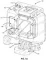
- FIG. laillustrates a perspective view of a camera system, according to one embodiment.
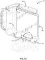
- FIG. 1 billustrates another alternative perspective view of a camera system, according to one embodiment.
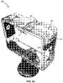
- FIG. 1 cillustrates a perspective view of a rear of the camera system, according to one embodiment.
- FIG. 2 aillustrates a perspective view of a camera for use with the camera system, according to one embodiment.
- FIG. 2 billustrates a perspective view of a rear of a camera for use with the camera system, according to one embodiment.
- FIG. 3 aillustrates a perspective view of a camera housing configured to enclose a camera, according to some embodiments.
- FIG. 3 billustrates a perspective view of a camera housing with a securing latch mechanism, according to some embodiments.
- FIG. 4 aillustrates a perspective view of a camera housing with a latch mechanism, according to some embodiments.
- FIG. 4 billustrates a close-up perspective view of a latch mechanism in an open position, according to some embodiments.
- FIG. 4 cillustrates a close-up perspective view of a latch mechanism in a closed position, according to some embodiments.
- FIGS. 5 a -5 cillustrate perspective views of a camera housing with a foldable handle mechanism configured to serve as a securing arm, according to some embodiments.
- a camera systemincludes a camera and a camera housing structured to at least partially enclose the camera.
- the cameraincludes a camera body having a camera lens structured on a front surface of the camera body, various indicators on the front of the surface of the camera body (such as LEDs, displays, and the like), various input mechanisms (such as buttons, switches, and touch-screen mechanisms), and electronics (e.g., imaging electronics, power electronics, etc.) internal to the camera body for capturing images via the camera lens and/or performing other functions.
- the camera housingcan include a lens window structured on the front surface of the camera housing and configured to substantially align with the camera lens, and can include one or more indicator windows structured on the front surface of the camera housing and configured to substantially align with the camera indicators.
- FIGS. 1 a and 1 billustrate various views of a camera system according to one example embodiment.
- the camera systemincludes, among other components, a camera housing 100 .
- a first housing portion 102includes a front face with four sides (i.e., a top side, bottom side, left side, and right side) structured to form a cavity that receives a camera (e.g. a still camera or video camera).
- the camera housing 100may not include one or more sides or faces.
- the camera housing 100may not include a front or back face (See FIGS. 3 a -5 c ), allowing the front face and rear face of the camera to be exposed when partially enclosed by the top side, bottom side, left side, and right side of the camera housing 100 .
- the camera housing 100has a small form factor (e.g., a height of approximately 2 to 7 centimeters, a width of approximately 2 to 7 centimeters, and a depth of approximately 1 to 5 centimeters), and is lightweight (e.g., approximately 50 to 150 grams).
- the camera housing 100can be rigid (or substantially rigid) (e.g., plastic, metal, fiberglass, etc.) or pliable (or substantially pliable) (e.g., leather, vinyl, neoprene, etc.).
- the camera housing 100may be appropriately configured for use in various elements.
- the camera housing 100may include a waterproof enclosure that protects a camera from water when used, for example, while surfing or scuba diving.
- Portions of the camera housing 100may include exposed areas to allow a user to manipulate buttons on the camera that are associated with the camera functionality. Alternatively, such areas may be covered with a pliable material to allow the user to manipulate the buttons through the camera housing 100 .
- the top face of the camera housing 100includes an outer shutter button 112 structured so that a shutter button 112 of the camera is substantially aligned with the outer shutter button 112 when the camera is secured within the camera housing 100 .
- the shutter button 112 of the camerais operationally coupled to the outer shutter button 112 so that pressing the outer shutter button 112 allows the user to operate the camera shutter button.
- the front face of the camera housing 100can include a lens window 104 structured so that a lens of the camera is substantially aligned with the lens windows 104 when the camera is secured within the camera housing 100 .
- the lens window 104can be adapted for use with a conventional lens, a wide angle lens, a flat lens, or any other specialized camera lens.
- the lens window 104includes a waterproof seal so as to maintain the waterproof aspect of the housing 100 .
- the camera housing 100includes one or more securing structures 120 for securing the camera housing 100 to one of a variety of mounting devices.
- FIG. 1 aillustrates the camera housing secured to a clip-style mount 122 .
- the camera housing 100includes a first plurality of protrusions (protrusions 124 as shown in FIG. 1 b ), and the mount 122 includes a second plurality of protrusions.
- Each protrusionincludes a hole (hole 126 as shown in FIG. 1 b ) at a similar location within the protrusion such that the first and second pluralities of protrusions can interlock in such a way that the protrusion holes substantially align.
- a turnable handscrewis inserted through the aligned holes, coupling the camera housing 100 to the mount 122 such that the camera housing can pivotally rotate relative to the mount when the turnable handscrew is in a first unlocked position, and such that the camera housing is fixed in position relative to the mount when the turnable handscrew is in a second locked position.
- the camera housing 100can be secured to a different type of mounting structure, and can be secured to a mounting structure via a different type of coupling mechanism.
- the camera mountcan in turn be optionally secured to a user's backpack, sports equipment, or body. This allows a user to use the camera for photography (e.g., in a hands-free configuration or manner) without having to physically hold, safeguard, or otherwise physically handle the camera.
- the camera housing 100includes an indicator window 106 structured so that one or more camera indicators are substantially aligned with the indicator window 106 when the camera is secured within the camera housing 100 .
- the indicator window 106can be any shape or size, and can be made of the same material as the remainder of the camera housing 100 , or can be made of any other material, for instance a transparent or translucent material and/or a non-reflective material.
- the described housing 100may also be adapted for a wider range of devices of varying shapes, sizes and dimensions besides cameras.
- an expansion modulemay be attached to housing 100 to add expanded features to electronic devices such as cell phones, music players, personal digital assistants (“PDAs”), global positioning system (“GPS”) units, or other portable electronic devices.
- PDAspersonal digital assistants
- GPSglobal positioning system
- FIG. 1 cis a rear perspective view of camera housing 100 illustrating a second housing portion 128 , according to one example embodiment.
- the second housing portion 128detachably couples with the first housing portion 102 opposite the front face of the first housing portion.
- the first housing portion 102 and second housing portion 128are collectively structured to enclose a camera within the cavity when the second housing portion 128 is secured to the first housing portion 102 in a closed position.
- the second housing portion 128can include a door 130 that allows the camera to be removed from the housing 100 .
- the door 130pivots around a hinge 136 that allows the door 130 to be opened or shut.
- a first fastening structure 138 located on the top face of the camera housing 100detachably couples to a second fastening structure 140 on the door 130 .
- the fastening structures 138 , 140secure the door 130 to the first portion 102 of the camera housing 100 in a closed position when coupled, as illustrated in FIG. 2 .
- the fastening structure 138includes a hook-shaped lateral bar and the fastening structure 140 comprises an L-shaped bar.
- fastening structure 138can pivot upwards to allow the door 130 to close and can then be pressed down around the fastening structure 140 to hold the door 130 in the closed position.
- fastening structures for securing the door 130can include, for example, a button assembly, a buckle assembly, a clip assembly, a hook and loop assembly, a magnet assembly, a ball and catch assembly, and an adhesive assembly, or any other type of securing mechanism.
- the hinge 136is instead located on the top face of the housing 100 and the fastening structures 138 , 140 are instead located on the bottom face of the housing 100 .
- the hinge 136 and fastening structures 138 , 140may be located on opposite side faces of the camera housing 100 .
- the housing 100includes a watertight seal so that the housing 100 is waterproof when the door 130 is shut.
- the door 130includes a sealing structure positioned on interior edges of the door 130 . The sealing structure provides a watertight seal between the first portion of the camera housing 102 and the door 130 when the first securing structure 138 on the top face of the camera housing 100 is coupled to the second securing structure 140 on the top edge of the door 130 .
- an outer hinge structure 132 on the bottom edge of the second housing portion 128detachably couples to an inner hinge structure 134 on the bottom edge of the first housing portion 102 to form the hinge 136 .
- the outer hinge structure 132includes one or more hook-shaped protrusions structured to securely fasten to a rod-shaped member of the inner hinge structure 134 .
- Other mechanisms for coupling the second housing portion 128 to the housing 100may also be used in various alternative embodiments.
- the second housing portion 128may be permanently attached to the first housing portion 102 .
- FIG. 2 aillustrates a camera 200 for use with the camera systems described herein, according to one example embodiment.
- the camera 200is configured to capture images and video, and to store captured images and video for subsequent display or playback.
- the camera 200is adapted to fit within a camera housing, such as the housing 100 discussed above or any other housing described herein.
- the camera 200includes a lens 202 configured to receive light incident upon the lens and to direct received light onto an image sensor internal to the lens.
- the lens 202is enclosed by a lens ring 204 .
- the camera 200can include various indicators, including the LED lights 206 and the LED display 208 shown in FIG. 2 a .
- the LED display 208is configured to substantially align with the indicator window 106 , and the LED lights 206 are configured to be visible through the housing 100 .
- the camera 200can also include buttons 210 configured to allow a user of the camera to interact with the camera, to turn the camera on, and to otherwise configure the operating mode of the camera.
- the camera 200can also include a microphone 212 configured to receive and record audio signals in conjunction with recording video.
- the side of the camera 200includes an I/O interface 214 . Though the embodiment of FIG. 2 a illustrates the I/O interface 214 enclosed by a protective door, the I/O interface can include any type or number of I/O ports or mechanisms, such as USC ports, HDMI ports, memory card slots, and the like.
- FIG. 2 billustrates a perspective view of a rear of a camera 200 for use with the camera system, according to one embodiment.
- the camera 200includes a door 216 that covers a removable battery and battery interface. The door 216 can be removed via the door release mechanism 218 .
- the cameraalso includes an expansion pack interface 220 configured to receive a removable expansion pack, such as a display module, an extra battery module, a wireless module, and the like. Removable expansion packs, when coupled to the camera 200 , provide additional functionality to the camera via the expansion pack interface 220 .
- FIG. 3 aillustrates a perspective view of camera housing 300 configured to enclose a camera, according to some embodiments.
- the camera housing 300includes a four-sided frame 320 that is configured to enclose a camera.
- the camera housing of FIG. 3 asecurely encloses the camera along the lateral sides of the camera (the top, bottom, left, and right sides) without obscuring the front and rear faces of the camera.
- the camera housing 300beneficially does not obstruct the camera lens, any LCD or other displays (front or rear), any optical indicators or buttons, and other user interface elements.
- the camera sidesare optionally covered with a layer of material (such as rubber) to provide frictional grip between the camera sides and the inner perimeter of the camera housing in an enclosed position.
- the camera housing 300includes the four-sided frame 320 , which includes a top side 320 - 1 (including segment 320 - 1 - a and 320 - 1 - b ), a bottom side 320 - 2 , a left side 320 - 3 , and a right side 320 - 4 .
- the four-sided frame 320is of a unibody construction.
- the four-sided frame 320can be constructed of one or more segments coupled together (e.g., glued, welded or stitched).
- the segment 320 - 1 - ais pivotally coupled to a first latch component, made up of latch-arm 350 - 1
- the segment 320 - 1 - bis pivotally coupled to a second latch component, made up of latch-arm 350 - 2 and latch-arm 350 - 3
- the first latch component and the second latch componentare pivotally coupled together to form the latch mechanism 350 .
- the latch mechanism 350is in a closed position (e.g., as explained further with reference to FIG. 3 b and FIG. 4 c )
- the framesecurely encloses a camera.
- the latch mechanismis in an open position (e.g., as explained further with reference to FIG. 3 a and FIG.
- the segment 320 - 1 - a and the segment 320 - 1 - bare separable, allowing for the insertion or removal of a camera.
- inserting a camera into or removing a camera from the framerequires the removal of the camera from the camera mount 390 .
- the latch mechanism 350allows the removal of the camera from the camera housing 320 without requiring the removal of the housing from the camera mount.
- the four-sided frame 320has a perimeter dimension that allows for the frame to fit the perimeter of the camera as further described with FIG. 3 b .
- top sidehas a length of approximately 2 to 7 centimeters, and a width of approximately 1 to 5 centimeters.
- latch-arm 350 - 1has a length of approximately 3 to 4 centimeters, and a width of approximately 0.25 to 1 centimeters, and the latch-arms 350 - 2 and 350 - 3 have lengths of approximately 2 to 3 centimeters, and widths of approximately 0.25 to 1 centimeters.
- the latch-arm 350 - 1includes a frame-coupled arm-end pivotally (e.g., rotatably) coupled to the segment 320 - 1 - a by a hinge mechanism 370 - 1 .
- the latch-arm 350 - 2 and the latch-arm 350 - 3each include corresponding frame-coupled arm-ends and pivotally couple to the segment 320 - 1 - b by hinge mechanisms 370 - 2 and 370 - 3 , respectively.
- the latch-arms 350 - 2 and 350 - 3form a single latch component in the embodiment of FIG. 3 a , in other embodiments, the latch-arms are separate/non-coupled components.
- the latch-arm 350 - 1is pivotally coupled to the latch-arms 350 - 2 and 350 - 3 by hinge mechanism 370 - 4 .
- the hinge mechanism 370 - 4allows the latch-arm 350 - 1 to pivotally rotate relative to the latch-arms 350 - 2 and 350 - 3 .
- the housing 320includes a plurality of protrusions (protrusions 385 - 1 and 385 - 2 ) protruding from the bottom side 320 - 2 of the housing.
- the protrusionsare configured to interlock with mating protrusions of the camera mount 390 .
- the plurality of protrusionsprotrude from the left side, the ride side, or the top of the camera housing.
- the latch mechanismis shown on the top side 320 - 1 of the camera housing, in alternative embodiments, the latch mechanism is located on a different side of the camera housing, such as the left side or the right side.
- the camera housing 300can be made of a mechanically compliant or pliable material (e.g., such as plastic, resin, or a polycarbonate material), allowing the frame to adequately flex and bend so as to enable insertion of a camera into and out of the frame.
- the latch componentscan be made of an electrically non-conductive material (e.g., such as plastic, or resin), to prevent or minimize electrical interference with an antenna located on the camera.
- camera housing 300has a height of approximately 4 to 6 centimeters, a width of approximately 5 to 7 centimeters, and a depth of approximately 1 to 4 centimeters).
- the camera housing 300can be made of an optically transparent, substantially transparent, translucent, or opaque material.
- camera housing 300is made of a water-proof or water-resistant material.
- FIG. 3 billustrates a perspective view of a camera housing 300 with a securing latch mechanism 350 , according to some embodiments.
- the cameraIn the closed position, the camera is substantially enclosed by the frame 320 and the inner perimeter of the frame 320 (perimeter P 1 ) is substantially equal to the outer lateral perimeter of the camera.
- the latch mechanismIn the closed position, the camera is securely enclosed inside the camera housing.
- the latch mechanism 350in the closed position, is substantially flush with the side 320 - 1 at location 396 and the side 320 - 4 at location 397 .
- the latchin the closed position, is flush with the rest of the frame thereby improving the aesthetic look of the camera housing.
- the uniform and seamless surface of the frame with the latch in the closed positione.g., due to the absence of exposed joints or crevices around the latch region
- the latch mechanism 350protrudes above a surface of side 320 - 1 at location 396 and above a surface of side 320 - 4 at location 397 .
- the latch mechanism 350may beneficially provide better reinforcement, strength, and stability and is thus more secure.
- the segment 320 - 1 - a and the segment 320 - 1 - bare separated by a first predefined separation distance, D 1 .
- the effective perimeter of the frame 320 , P 1is substantially equal to a lateral perimeter of the camera.
- the segments 320 - 1 - a and 320 - 1 - bare substantially in contact, reducing the effective distance D 1 to essentially zero.
- the segment 320 - 1 - bincludes a segment boundary surrounding a gap 380 configured to receive the latch mechanism 350 in the closed position (e.g., as shown in FIG. 3 b ) such that, in the closed position, the latch mechanism 350 occupies the gap 380 and is surrounded by the segment boundary.
- lengthwise portions of the segment boundary formed along the length of the segment 320 - 1 - bare rigidly connected by a widthwise supporting member (member 395 of FIG. 3 b ), thereby securing a fixed separation between the lengthwise portions of the segment boundary. This makes it possible for the latch mechanism 350 to open without pushing the segment boundaries laterally outward, thereby constraining the top side of the frame in its original shape in a lateral direction.
- FIG. 4 aillustrates another perspective view of camera housing 300 with latch mechanism 350 , according to some embodiments.
- the latch mechanism 350In the open position, the latch mechanism 350 is lifted outward from the frame 320 , thereby allowing the segment 320 - 1 - a and the segment 320 - 1 - b to separate from each other.
- the inner perimeter of the frame 320With segments 320 - 1 - a and 320 - 1 - b separated, the inner perimeter of the frame 320 is enlarged to an effective perimeter, P 2 , larger than the outer lateral perimeter of the camera, thereby allowing insertion or removal of the camera into or out of the frame.
- the space D 2 between segments 320 - 1 - a and 320 - 1 - bincreases or decreases when the latch mechanism is in the open position as the latch arm 350 - 1 pivotally rotates relative to the latch-arms 350 - 2 and 350 - 3 .
- camera housing 300further includes one or more respective openings (e.g., openings or apertures 420 - 1 and 420 - 1 ) to accommodate one or more of: a camera power button, a data port, a microphone interface, and the like. These openings on the frame align with corresponding camera features when the camera is securely enclosed within the housing, allowing for convenient access to camera functionality without having to remove the camera from the housing.
- openings or apertures 420 - 1 and 420 - 1to accommodate one or more of: a camera power button, a data port, a microphone interface, and the like.
- FIG. 4 billustrates a close-up perspective view of latch mechanism 350 in an open position, according to some embodiments.
- the latch components 350 - 1 , 350 - 2 , and 350 - 3each form an angular separation relative to the top side of the frame 320 .
- latch-arm 350 - 1forms an angular separation A 1 with respect to the top side of the frame 320
- latch-arm 350 - 2forms an angular separation A 2 with respect to the top side of the frame 320
- latch-arm 350 - 1forms an angular separation A 3 with respect to latch-arm 350 - 2 .
- the angles A 2 and A 3increase, and A 1 decreases.
- the segments 320 - 1 - a and 320 - 1 - bare separated, causing latch-arm 350 - 1 to pivot angularly away from latch-arms 350 - 2 and 350 - 3 , the angle A 3 increases.
- FIG. 4 cillustrates a close-up perspective view of latch mechanism 350 in a closed position, according to some embodiments.
- the segment 320 - 1 - a and the segment 320 - 1 - bare separated by the distance D 1 .
- the segment 320 - 1 - bterminates in a slice 450 of compressible material (e.g., a piece of rubber) configured to seal a gap, if present, between the segments 320 - 1 - a and 320 - 1 - b when the latch mechanism is in the closed position.
- compressible materiale.g., a piece of rubber
- the latch components 350 - 1 , 350 - 2 and 350 - 3include a substantially right-angled bend configured to fold over a corner 460 adjacent to the second segment 320 - 1 - b .
- the right-angled bendallows the latch mechanism to be flush with the top side of the housing, the adjacent side of the housing, and the corner of the housing where the top side and the adjacent side intersect.
- FIGS. 5 a -5 cillustrate perspective views of a camera housing 300 with a foldable handle mechanism 520 configured to serve as a securing arm, according to some embodiments.
- foldable handle 520serves as a securing retainer configured to accommodate and secure extension modules coupled to a camera body.
- the foldable handle 520includes a first arm 530 - 1 and a second perpendicular arm 530 - 2 , pivotally coupled to a side of the camera housing.
- FIGS. 5 a and 5 billustrate the handle 520 in a first position configured to secure a camera and coupled extension module 534 .
- the camera housingcan include a reciprocal indentation 540 configured to accommodate the handle when folded downward into a second position (as illustrated in FIG. 5 c ). The reciprocal indentation allows the handle to be flush with the inside walls of the camera housing when in the second position.
- Coupledalong with its derivatives.
- the term “coupled” as used hereinis not necessarily limited to two or more elements being in direct physical or electrical contact. Rather, the term “coupled” may also encompass two or more elements are not in direct contact with each other, but yet still co-operate or interact with each other, or are structured to provide a thermal conduction path between the elements.
- the terms “comprises,” “comprising,” “includes,” “including,” “has,” “having” or any other variation thereof,are intended to cover a non-exclusive inclusion.
- a process, method, article, or apparatus that comprises a list of elementsis not necessarily limited to only those elements but may include other elements not expressly listed or inherent to such process, method, article, or apparatus.
- any reference to “one embodiment” or “an embodiment”means that a particular element, feature, structure, or characteristic described in connection with the embodiment is included in at least one embodiment.
- the appearances of the phrase “in one embodiment” in various places in the specificationare not necessarily all referring to the same embodiment.
Landscapes
- Physics & Mathematics (AREA)
- General Physics & Mathematics (AREA)
- Studio Devices (AREA)
Abstract
Description
Claims (20)
Priority Applications (4)
| Application Number | Priority Date | Filing Date | Title |
|---|---|---|---|
| US16/935,873US11150542B2 (en) | 2013-07-23 | 2020-07-22 | Camera housing |
| US17/490,422US11714338B2 (en) | 2013-07-23 | 2021-09-30 | Camera housing |
| US18/221,100US12222633B2 (en) | 2013-07-23 | 2023-07-12 | Camera housing |
| US19/012,030US20250147394A1 (en) | 2013-07-23 | 2025-01-07 | Camera housing |
Applications Claiming Priority (7)
| Application Number | Priority Date | Filing Date | Title |
|---|---|---|---|
| US13/949,160US8837928B1 (en) | 2013-07-23 | 2013-07-23 | Camera housing |
| US14/459,650US9268200B2 (en) | 2013-07-23 | 2014-08-14 | Camera housing |
| US14/995,599US9628681B2 (en) | 2013-07-23 | 2016-01-14 | Camera housing |
| US15/487,534US9930231B2 (en) | 2013-07-23 | 2017-04-14 | Camera housing |
| US15/937,004US10511750B2 (en) | 2013-07-23 | 2018-03-27 | Camera housing |
| US16/515,342US10754229B2 (en) | 2013-07-23 | 2019-07-18 | Camera housing |
| US16/935,873US11150542B2 (en) | 2013-07-23 | 2020-07-22 | Camera housing |
Related Parent Applications (1)
| Application Number | Title | Priority Date | Filing Date |
|---|---|---|---|
| US16/515,342ContinuationUS10754229B2 (en) | 2013-07-23 | 2019-07-18 | Camera housing |
Related Child Applications (1)
| Application Number | Title | Priority Date | Filing Date |
|---|---|---|---|
| US17/490,422ContinuationUS11714338B2 (en) | 2013-07-23 | 2021-09-30 | Camera housing |
Publications (2)
| Publication Number | Publication Date |
|---|---|
| US20200348584A1 US20200348584A1 (en) | 2020-11-05 |
| US11150542B2true US11150542B2 (en) | 2021-10-19 |
Family
ID=51493462
Family Applications (10)
| Application Number | Title | Priority Date | Filing Date |
|---|---|---|---|
| US13/949,160ActiveUS8837928B1 (en) | 2013-07-23 | 2013-07-23 | Camera housing |
| US14/459,650ActiveUS9268200B2 (en) | 2013-07-23 | 2014-08-14 | Camera housing |
| US14/995,599ActiveUS9628681B2 (en) | 2013-07-23 | 2016-01-14 | Camera housing |
| US15/487,534ActiveUS9930231B2 (en) | 2013-07-23 | 2017-04-14 | Camera housing |
| US15/937,004ActiveUS10511750B2 (en) | 2013-07-23 | 2018-03-27 | Camera housing |
| US16/515,342ActiveUS10754229B2 (en) | 2013-07-23 | 2019-07-18 | Camera housing |
| US16/935,873ActiveUS11150542B2 (en) | 2013-07-23 | 2020-07-22 | Camera housing |
| US17/490,422ActiveUS11714338B2 (en) | 2013-07-23 | 2021-09-30 | Camera housing |
| US18/221,100ActiveUS12222633B2 (en) | 2013-07-23 | 2023-07-12 | Camera housing |
| US19/012,030PendingUS20250147394A1 (en) | 2013-07-23 | 2025-01-07 | Camera housing |
Family Applications Before (6)
| Application Number | Title | Priority Date | Filing Date |
|---|---|---|---|
| US13/949,160ActiveUS8837928B1 (en) | 2013-07-23 | 2013-07-23 | Camera housing |
| US14/459,650ActiveUS9268200B2 (en) | 2013-07-23 | 2014-08-14 | Camera housing |
| US14/995,599ActiveUS9628681B2 (en) | 2013-07-23 | 2016-01-14 | Camera housing |
| US15/487,534ActiveUS9930231B2 (en) | 2013-07-23 | 2017-04-14 | Camera housing |
| US15/937,004ActiveUS10511750B2 (en) | 2013-07-23 | 2018-03-27 | Camera housing |
| US16/515,342ActiveUS10754229B2 (en) | 2013-07-23 | 2019-07-18 | Camera housing |
Family Applications After (3)
| Application Number | Title | Priority Date | Filing Date |
|---|---|---|---|
| US17/490,422ActiveUS11714338B2 (en) | 2013-07-23 | 2021-09-30 | Camera housing |
| US18/221,100ActiveUS12222633B2 (en) | 2013-07-23 | 2023-07-12 | Camera housing |
| US19/012,030PendingUS20250147394A1 (en) | 2013-07-23 | 2025-01-07 | Camera housing |
Country Status (5)
| Country | Link |
|---|---|
| US (10) | US8837928B1 (en) |
| EP (1) | EP3025193B1 (en) |
| CN (2) | CN110426910B (en) |
| DE (1) | DE202014011346U1 (en) |
| WO (1) | WO2015013054A1 (en) |
Cited By (1)
| Publication number | Priority date | Publication date | Assignee | Title |
|---|---|---|---|---|
| US11714338B2 (en) | 2013-07-23 | 2023-08-01 | Gopro, Inc. | Camera housing |
Families Citing this family (72)
| Publication number | Priority date | Publication date | Assignee | Title |
|---|---|---|---|---|
| US9268201B1 (en)* | 2012-12-24 | 2016-02-23 | John Montgomery | Breakaway magnetic mount |
| US9030606B2 (en)* | 2013-03-14 | 2015-05-12 | Gopro, Inc. | Wireless camera housing illuminators |
| US9395603B2 (en)* | 2013-09-19 | 2016-07-19 | Kenneth John Achenbach | Camera positioning and mounting system with improved mouth adapter |
| US20150189132A1 (en)* | 2014-01-02 | 2015-07-02 | Matt Sandy | Article of clothing |
| US8992102B1 (en)* | 2014-01-06 | 2015-03-31 | Gopro, Inc. | Camera housing for a square-profile camera |
| US9383630B2 (en) | 2014-03-05 | 2016-07-05 | Mygo, Llc | Camera mouth mount |
| USD750146S1 (en) | 2014-05-30 | 2016-02-23 | Gopro, Inc. | Camera housing |
| US9625127B2 (en)* | 2014-05-31 | 2017-04-18 | Industralight, Llc | Rugged lighting system |
| US9681029B2 (en) | 2014-10-02 | 2017-06-13 | Gopro, Inc. | Swivel camera mount |
| AU2015336085B2 (en) | 2014-10-20 | 2018-08-30 | Axon Enterprise, Inc. | Systems and methods for distributed control |
| US10194071B2 (en) | 2015-04-03 | 2019-01-29 | Red.Com, Llc | Modular motion camera |
| CA3029573A1 (en) | 2015-04-03 | 2016-10-06 | Red.Com, Llc | Modular motion camera |
| USD778335S1 (en) | 2015-05-05 | 2017-02-07 | Gopro, Inc. | Camera |
| CN104994258A (en)* | 2015-06-16 | 2015-10-21 | 成都西可科技有限公司 | Equipment for achieving video and picture shooting of outdoor sports |
| US20170007011A1 (en)* | 2015-07-06 | 2017-01-12 | Larry Tang | Protective Case for Electronic Camcorders for Air, Land and Underwater Use Employing User Securements |
| US10192277B2 (en) | 2015-07-14 | 2019-01-29 | Axon Enterprise, Inc. | Systems and methods for generating an audit trail for auditable devices |
| JP6653427B2 (en)* | 2015-08-06 | 2020-02-26 | パナソニックIpマネジメント株式会社 | Electronic equipment and terminal cover unit |
| USD785069S1 (en) | 2015-09-01 | 2017-04-25 | Avant Technology, Inc. | Camera housing |
| USD794697S1 (en) | 2015-09-01 | 2017-08-15 | Avant Technology, Inc. | Expansion module for a camera |
| USD785068S1 (en) | 2015-09-02 | 2017-04-25 | Go Cube, Inc. | Camera housing |
| US10101637B2 (en) | 2015-09-11 | 2018-10-16 | Avant Technology, Inc. | Camera case with removable carrier, filter receiver, external battery and supplemental memory storage |
| USD827762S1 (en)* | 2015-10-29 | 2018-09-04 | Did, Inc. | Stun gun |
| US9995990B2 (en) | 2015-12-15 | 2018-06-12 | Gopro, Inc. | Removable camera lens cover |
| USD830446S1 (en) | 2015-12-15 | 2018-10-09 | Gopro, Inc. | Multi-lens camera |
| USD776741S1 (en) | 2015-12-29 | 2017-01-17 | Gopro, Inc. | Camera dive housing |
| USD869844S1 (en)* | 2016-01-19 | 2019-12-17 | Nexark, Inc. | Low profile case |
| USD810175S1 (en)* | 2016-05-02 | 2018-02-13 | Hanwha Techwin Co., Ltd. | Camera |
| US9864257B1 (en)* | 2016-09-19 | 2018-01-09 | Gopro, Inc. | Camera frame with side door |
| US10582094B2 (en)* | 2016-09-21 | 2020-03-03 | Gopro, Inc. | Camera mount stand and cover |
| US11134181B2 (en) | 2017-01-03 | 2021-09-28 | Gopro, Inc. | Remote image capture and mounting ecosystem |
| US10694082B2 (en)* | 2017-05-02 | 2020-06-23 | John Immel | Fin shaped underwater camera housing and system incorporating same |
| EP3673474B1 (en) | 2017-09-27 | 2023-05-17 | Zhejiang Dahua Technology Co., Ltd. | A surveillance device |
| USD861592S1 (en) | 2017-09-28 | 2019-10-01 | Gopro, Inc. | Battery |
| USD890835S1 (en)* | 2017-12-28 | 2020-07-21 | Gopro, Inc. | Camera |
| USD880569S1 (en)* | 2018-03-28 | 2020-04-07 | Zhongshan Forever Photographic Equipment Co. Ltd. | Camera cover |
| CN108506683A (en)* | 2018-05-16 | 2018-09-07 | 东莞市凯安机械配件有限公司 | A kind of shooting holder |
| US11215906B2 (en)* | 2018-06-11 | 2022-01-04 | Mgmd Brainpower Llc | Camera accessory housing device |
| US11115586B2 (en) | 2018-06-25 | 2021-09-07 | WildTech@Resolve, LLC | Systems and methods for covertly monitoring an environment |
| EP3834039B1 (en) | 2018-08-07 | 2024-03-27 | GoPro, Inc. | Camera and camera mount |
| CN208724024U (en)* | 2018-08-16 | 2019-04-09 | 深圳市大疆创新科技有限公司 | Cases and Camera Systems |
| USD907101S1 (en) | 2019-06-11 | 2021-01-05 | Gopro, Inc. | Camera |
| USD894256S1 (en) | 2018-08-31 | 2020-08-25 | Gopro, Inc. | Camera mount |
| USD905786S1 (en) | 2018-08-31 | 2020-12-22 | Gopro, Inc. | Camera mount |
| USD907680S1 (en) | 2018-08-31 | 2021-01-12 | Gopro, Inc. | Camera |
| USD903740S1 (en) | 2018-09-14 | 2020-12-01 | Gopro, Inc. | Camera |
| FR3088169B1 (en)* | 2018-11-13 | 2021-06-18 | Dussau Distrib | SURVEILLANCE AND INTERVENTION KIT FOR LIVESTOCK PREMISES |
| USD920419S1 (en) | 2019-09-17 | 2021-05-25 | Gopro, Inc. | Camera |
| USD1029745S1 (en) | 2019-09-13 | 2024-06-04 | Gopro, Inc. | Camera battery |
| USD949222S1 (en) | 2019-09-17 | 2022-04-19 | Gopro, Inc. | Camera housing |
| DE212020000722U1 (en) | 2019-09-18 | 2022-04-26 | Gopro, Inc. | door assemblies for imaging devices |
| US12066748B2 (en) | 2019-09-18 | 2024-08-20 | Gopro, Inc. | Door assemblies for image capture devices |
| US11425286B2 (en) | 2020-03-31 | 2022-08-23 | Gopro, Inc. | Housing assembly for image capture devices |
| US11630376B2 (en) | 2020-06-18 | 2023-04-18 | Gopro, Inc. | Removable lens accessories for image capture devices |
| USD947920S1 (en) | 2020-06-30 | 2022-04-05 | Gopro, Inc. | Camera housing |
| WO2022000417A1 (en) | 2020-07-02 | 2022-01-06 | Gopro, Inc. | Removable battery door assemblies for image capture devices |
| USD1029746S1 (en) | 2020-07-31 | 2024-06-04 | Gopro, Inc. | Battery |
| USD1050227S1 (en) | 2020-08-14 | 2024-11-05 | Gopro, Inc. | Camera door |
| USD946074S1 (en) | 2020-08-14 | 2022-03-15 | Gopro, Inc. | Camera |
| USD967890S1 (en) | 2020-08-28 | 2022-10-25 | Gopro, Inc. | Camera lens attachment |
| USD974450S1 (en) | 2020-08-28 | 2023-01-03 | Gopro, Inc. | Camera lens attachment |
| US11528417B2 (en) | 2020-08-31 | 2022-12-13 | Gopro, Inc. | Calibrating an image capture device with a detachable lens |
| US11600023B2 (en) | 2020-08-31 | 2023-03-07 | Gopro, Inc. | Optical center calibration |
| USD1066462S1 (en) | 2021-02-12 | 2025-03-11 | Gopro, Inc. | Camera door |
| USD1001873S1 (en)* | 2021-07-08 | 2023-10-17 | Zhongshan Forever Photographic Equipment Co. Ltd | Camera mount |
| USD1001872S1 (en)* | 2021-07-08 | 2023-10-17 | Zhongshan Forever Photographic Equipment Co. Ltd | Camera mount |
| PL246648B1 (en)* | 2022-03-02 | 2025-02-17 | Politechnika Gdanska | A housing for a device with a photographic function that protects against damage caused by high temperatures and moisture during the steam sterilization process. |
| USD1061682S1 (en) | 2022-08-04 | 2025-02-11 | Gopro, Inc. | Camera door |
| US12321084B2 (en) | 2022-08-12 | 2025-06-03 | Gopro, Inc. | Interconnect mechanism for image capture device |
| US12379650B2 (en) | 2023-02-15 | 2025-08-05 | Gopro, Inc. | Reinforced image capture devices including interconnect mechanisms with a threaded accessory interface |
| US12055842B1 (en) | 2024-01-30 | 2024-08-06 | Greatest Generation, LLC | Cold-weather resilience cover for electronics assembly |
| USD1096914S1 (en) | 2024-03-15 | 2025-10-07 | Gopro, Inc. | Camera mount |
| US12360442B1 (en)* | 2024-10-23 | 2025-07-15 | Caleb Pike | Camera mounting system |
Citations (46)
| Publication number | Priority date | Publication date | Assignee | Title |
|---|---|---|---|---|
| US1612277A (en) | 1922-11-03 | 1926-12-28 | Drop Head Projector Company | Housing for portable motion-picture machines |
| US5092458A (en) | 1990-06-20 | 1992-03-03 | Sony Corporation | Waterproof case for camera |
| US6138826A (en) | 1998-02-02 | 2000-10-31 | Fuji Photo Film Co., Ltd. | Waterproof case for camera |
| JP2003107569A (en)* | 2001-09-26 | 2003-04-09 | Sony Corp | Waterproof housing |
| US20040095506A1 (en) | 2002-11-18 | 2004-05-20 | Scott David Alan | Generic, non-mechanical control of cameras in hostile environments |
| CN1740899A (en) | 2004-08-25 | 2006-03-01 | 索尼公司 | Water-resistant case for electronic devices |
| US7060921B2 (en) | 2004-08-25 | 2006-06-13 | Sony Corporation | Water-resistant case for electronic devices |
| US20070071423A1 (en) | 2005-09-27 | 2007-03-29 | Fantone Stephen J | Underwater adaptive camera housing |
| US20080023607A1 (en) | 2004-03-17 | 2008-01-31 | Trek Technologies, Llc, Dba Trek Tech | Magnetic-based releasable, adjustable camera or other device mount apparatus |
| US20090032420A1 (en) | 2007-08-03 | 2009-02-05 | Sony Corporation | Waterproof case for electronic device |
| US20090111543A1 (en) | 2007-10-31 | 2009-04-30 | Hong Fu Jin Precision Industry (Shenzhen) Co., Ltd. | Protective sleeve for portable electronic devices |
| US20090110380A1 (en) | 2007-10-30 | 2009-04-30 | Optikos Corporation | Underwater adaptive camera housing |
| US20090206077A1 (en) | 2008-02-19 | 2009-08-20 | Daymen Photo Marketing Lp, A Canadian Limited Partnership | Protective Camera Enclosure |
| US7613386B2 (en) | 2001-03-21 | 2009-11-03 | Ricoh Company, Ltd. | Waterproof case for portable device |
| CN101614941A (en) | 2008-06-26 | 2009-12-30 | 郑银芳 | A kind of portable motile waterproof camera |
| WO2010005975A1 (en) | 2008-07-07 | 2010-01-14 | Woodman Labs | Camera housing with integrated expansion module |
| WO2010005976A1 (en) | 2008-07-07 | 2010-01-14 | Woodman Labs | Mount system for attaching camera to a sport board |
| US20110064401A1 (en) | 2009-09-11 | 2011-03-17 | Desorbo Alexander P | Coupling and accessory system for electronic devices |
| CN201796220U (en) | 2010-08-25 | 2011-04-13 | 上海龙达胜宝利光电有限公司 | Lock latch applied on hunting digital camera |
| US20110147245A1 (en) | 2009-12-21 | 2011-06-23 | Zear Corporation Limited | Waterproof camera case with a lock mechanism |
| US20110297578A1 (en) | 2010-06-04 | 2011-12-08 | Kurt Stiehl | Ring-Shaped Cover for Portable Electronic Device |
| US20120043236A1 (en) | 2010-08-23 | 2012-02-23 | Peter Szucs | Mobile Device Vessel |
| US20120133758A1 (en) | 2010-11-30 | 2012-05-31 | Doug Foss | Underwater camera control |
| CN202353622U (en) | 2011-11-04 | 2012-07-25 | 东莞祥富五金制品有限公司 | A buckle-type mobile phone protective frame |
| US20120262618A1 (en) | 2011-04-14 | 2012-10-18 | Amphibian Labs Llc | Waterproof case for hand held computing device |
| US20130082963A1 (en) | 2011-10-03 | 2013-04-04 | Man Fong CHU | Waterproof housing for digital devices having capacitive touch screen and its actuator mechanism |
| US20130250134A1 (en) | 2012-02-19 | 2013-09-26 | Jack J. McCauley | System and Methods for Wireless Remote Control over Cameras |
| US20130324189A1 (en) | 2012-05-31 | 2013-12-05 | Voxer Ip Llc | Smart case for mobile comunication devices |
| US20130331976A1 (en) | 2010-06-03 | 2013-12-12 | Minute Key Inc. | Key duplicating system |
| USD699276S1 (en) | 2012-10-10 | 2014-02-11 | Woodman Labs, Inc. | Camera housing |
| USD699277S1 (en) | 2012-10-10 | 2014-02-11 | Woodman Labs, Inc. | Camera housing |
| US20140069824A1 (en) | 2012-09-11 | 2014-03-13 | Andrey Kalashnikov | Protective bumper case |
| US20140099093A1 (en) | 2012-10-04 | 2014-04-10 | Joseph M. JOHNSON, SR. | Extendible l-plate for camera equipment |
| US8749966B1 (en) | 2009-12-22 | 2014-06-10 | Emc Corporation | Data storage drive carrier |
| US8807849B2 (en) | 2011-10-12 | 2014-08-19 | Padcaster Llc | Frame and insert for mounting mobile device to a tripod |
| US8825124B1 (en) | 2013-04-22 | 2014-09-02 | Matthew P. Davies | Interactive protective smart case with touchscreen display and laser pointer for the display and broadcast of images, video, and audio respectively from a smartphone |
| US8837928B1 (en) | 2013-07-23 | 2014-09-16 | Gopro, Inc. | Camera housing |
| US9014766B2 (en) | 2012-07-20 | 2015-04-21 | Taer Innovation Co., Ltd. | Protective clamp frame having power and unclamp duplex button for mobile communication devices |
| US20150180527A1 (en) | 2013-12-24 | 2015-06-25 | Incipio Technologies, Inc. | Protective case for mobile device with displaced camera control |
| US20150264226A1 (en) | 2014-03-14 | 2015-09-17 | Eran Gafni | Methods and devices for providing electrical energy and data through a protective case |
| US9152019B2 (en) | 2012-11-05 | 2015-10-06 | 360 Heros, Inc. | 360 degree camera mount and related photographic and video system |
| US20150288892A1 (en) | 2009-03-02 | 2015-10-08 | Flir Systems, Inc. | Device attachment with infrared imaging sensor |
| US9161110B1 (en) | 2014-09-19 | 2015-10-13 | Speaqua Corp. | Loudspeaker mount |
| US9300345B2 (en) | 2013-04-05 | 2016-03-29 | Really Right Stuff, Llc | Conductive case for electronic camera device |
| US20160219202A1 (en) | 2015-01-27 | 2016-07-28 | Moment, Inc. | Integrated Multi-Functional Case For Mobile Photography |
| US20170060184A1 (en) | 2015-08-28 | 2017-03-02 | Vals Tech Inc. | Waterproof housing with swing arm actuator for use with digital devices and method |
Family Cites Families (3)
| Publication number | Priority date | Publication date | Assignee | Title |
|---|---|---|---|---|
| US3813017A (en)* | 1972-02-22 | 1974-05-28 | J Pimsleur | Camera holster |
| JPS6165439U (en)* | 1984-08-31 | 1986-05-06 | ||
| US7426339B2 (en)* | 2004-11-30 | 2008-09-16 | Olympus Corporation | Waterproof housing |
- 2013
- 2013-07-23USUS13/949,160patent/US8837928B1/enactiveActive
- 2014
- 2014-07-14WOPCT/US2014/046552patent/WO2015013054A1/enactiveApplication Filing
- 2014-07-14CNCN201910681389.3Apatent/CN110426910B/enactiveActive
- 2014-07-14DEDE202014011346.7Upatent/DE202014011346U1/ennot_activeExpired - Lifetime
- 2014-07-14CNCN201480046598.6Apatent/CN105474089B/enactiveActive
- 2014-07-14EPEP14829354.1Apatent/EP3025193B1/enactiveActive
- 2014-08-14USUS14/459,650patent/US9268200B2/enactiveActive
- 2016
- 2016-01-14USUS14/995,599patent/US9628681B2/enactiveActive
- 2017
- 2017-04-14USUS15/487,534patent/US9930231B2/enactiveActive
- 2018
- 2018-03-27USUS15/937,004patent/US10511750B2/enactiveActive
- 2019
- 2019-07-18USUS16/515,342patent/US10754229B2/enactiveActive
- 2020
- 2020-07-22USUS16/935,873patent/US11150542B2/enactiveActive
- 2021
- 2021-09-30USUS17/490,422patent/US11714338B2/enactiveActive
- 2023
- 2023-07-12USUS18/221,100patent/US12222633B2/enactiveActive
- 2025
- 2025-01-07USUS19/012,030patent/US20250147394A1/enactivePending
Patent Citations (54)
| Publication number | Priority date | Publication date | Assignee | Title |
|---|---|---|---|---|
| US1612277A (en) | 1922-11-03 | 1926-12-28 | Drop Head Projector Company | Housing for portable motion-picture machines |
| US5092458A (en) | 1990-06-20 | 1992-03-03 | Sony Corporation | Waterproof case for camera |
| US6138826A (en) | 1998-02-02 | 2000-10-31 | Fuji Photo Film Co., Ltd. | Waterproof case for camera |
| US7613386B2 (en) | 2001-03-21 | 2009-11-03 | Ricoh Company, Ltd. | Waterproof case for portable device |
| JP2003107569A (en)* | 2001-09-26 | 2003-04-09 | Sony Corp | Waterproof housing |
| US20040095506A1 (en) | 2002-11-18 | 2004-05-20 | Scott David Alan | Generic, non-mechanical control of cameras in hostile environments |
| US20080023607A1 (en) | 2004-03-17 | 2008-01-31 | Trek Technologies, Llc, Dba Trek Tech | Magnetic-based releasable, adjustable camera or other device mount apparatus |
| CN1740899A (en) | 2004-08-25 | 2006-03-01 | 索尼公司 | Water-resistant case for electronic devices |
| US7060921B2 (en) | 2004-08-25 | 2006-06-13 | Sony Corporation | Water-resistant case for electronic devices |
| CN100432830C (en) | 2004-08-25 | 2008-11-12 | 索尼株式会社 | Water-resistant case for electronic devices |
| US20070071423A1 (en) | 2005-09-27 | 2007-03-29 | Fantone Stephen J | Underwater adaptive camera housing |
| US20090032420A1 (en) | 2007-08-03 | 2009-02-05 | Sony Corporation | Waterproof case for electronic device |
| US20090110380A1 (en) | 2007-10-30 | 2009-04-30 | Optikos Corporation | Underwater adaptive camera housing |
| US7801425B2 (en) | 2007-10-30 | 2010-09-21 | Optikos Corporation | Underwater adaptive camera housing |
| US20090111543A1 (en) | 2007-10-31 | 2009-04-30 | Hong Fu Jin Precision Industry (Shenzhen) Co., Ltd. | Protective sleeve for portable electronic devices |
| US20090206077A1 (en) | 2008-02-19 | 2009-08-20 | Daymen Photo Marketing Lp, A Canadian Limited Partnership | Protective Camera Enclosure |
| CN101614941A (en) | 2008-06-26 | 2009-12-30 | 郑银芳 | A kind of portable motile waterproof camera |
| WO2010005976A1 (en) | 2008-07-07 | 2010-01-14 | Woodman Labs | Mount system for attaching camera to a sport board |
| US20100060747A1 (en) | 2008-07-07 | 2010-03-11 | Woodman Nicholas D | Camera Housing With Integrated Expansion Module |
| WO2010005975A1 (en) | 2008-07-07 | 2010-01-14 | Woodman Labs | Camera housing with integrated expansion module |
| US20130057758A1 (en) | 2008-07-07 | 2013-03-07 | Nicholas D. Woodman | Camera Housing With Integrated Expansion Module |
| US8014656B2 (en) | 2008-07-07 | 2011-09-06 | Woodman Labs | Mount system for attaching camera to a sport board |
| US20150288892A1 (en) | 2009-03-02 | 2015-10-08 | Flir Systems, Inc. | Device attachment with infrared imaging sensor |
| US20110064401A1 (en) | 2009-09-11 | 2011-03-17 | Desorbo Alexander P | Coupling and accessory system for electronic devices |
| US8544643B2 (en) | 2009-12-21 | 2013-10-01 | Zear Corporation Limited | Waterproof camera case with a lock mechanism |
| US20110147245A1 (en) | 2009-12-21 | 2011-06-23 | Zear Corporation Limited | Waterproof camera case with a lock mechanism |
| US8749966B1 (en) | 2009-12-22 | 2014-06-10 | Emc Corporation | Data storage drive carrier |
| US20130331976A1 (en) | 2010-06-03 | 2013-12-12 | Minute Key Inc. | Key duplicating system |
| US20110297578A1 (en) | 2010-06-04 | 2011-12-08 | Kurt Stiehl | Ring-Shaped Cover for Portable Electronic Device |
| US20120043236A1 (en) | 2010-08-23 | 2012-02-23 | Peter Szucs | Mobile Device Vessel |
| CN201796220U (en) | 2010-08-25 | 2011-04-13 | 上海龙达胜宝利光电有限公司 | Lock latch applied on hunting digital camera |
| US20120133758A1 (en) | 2010-11-30 | 2012-05-31 | Doug Foss | Underwater camera control |
| US20120262618A1 (en) | 2011-04-14 | 2012-10-18 | Amphibian Labs Llc | Waterproof case for hand held computing device |
| US20130082963A1 (en) | 2011-10-03 | 2013-04-04 | Man Fong CHU | Waterproof housing for digital devices having capacitive touch screen and its actuator mechanism |
| US8807849B2 (en) | 2011-10-12 | 2014-08-19 | Padcaster Llc | Frame and insert for mounting mobile device to a tripod |
| CN202353622U (en) | 2011-11-04 | 2012-07-25 | 东莞祥富五金制品有限公司 | A buckle-type mobile phone protective frame |
| US20130250134A1 (en) | 2012-02-19 | 2013-09-26 | Jack J. McCauley | System and Methods for Wireless Remote Control over Cameras |
| US20130324189A1 (en) | 2012-05-31 | 2013-12-05 | Voxer Ip Llc | Smart case for mobile comunication devices |
| US9014766B2 (en) | 2012-07-20 | 2015-04-21 | Taer Innovation Co., Ltd. | Protective clamp frame having power and unclamp duplex button for mobile communication devices |
| US20140069824A1 (en) | 2012-09-11 | 2014-03-13 | Andrey Kalashnikov | Protective bumper case |
| US20140099093A1 (en) | 2012-10-04 | 2014-04-10 | Joseph M. JOHNSON, SR. | Extendible l-plate for camera equipment |
| USD699277S1 (en) | 2012-10-10 | 2014-02-11 | Woodman Labs, Inc. | Camera housing |
| USD724638S1 (en) | 2012-10-10 | 2015-03-17 | Gopro, Inc. | Camera housing |
| USD724637S1 (en) | 2012-10-10 | 2015-03-17 | Gopro, Inc. | Camera housing |
| USD699276S1 (en) | 2012-10-10 | 2014-02-11 | Woodman Labs, Inc. | Camera housing |
| US9152019B2 (en) | 2012-11-05 | 2015-10-06 | 360 Heros, Inc. | 360 degree camera mount and related photographic and video system |
| US9300345B2 (en) | 2013-04-05 | 2016-03-29 | Really Right Stuff, Llc | Conductive case for electronic camera device |
| US8825124B1 (en) | 2013-04-22 | 2014-09-02 | Matthew P. Davies | Interactive protective smart case with touchscreen display and laser pointer for the display and broadcast of images, video, and audio respectively from a smartphone |
| US8837928B1 (en) | 2013-07-23 | 2014-09-16 | Gopro, Inc. | Camera housing |
| US20150180527A1 (en) | 2013-12-24 | 2015-06-25 | Incipio Technologies, Inc. | Protective case for mobile device with displaced camera control |
| US20150264226A1 (en) | 2014-03-14 | 2015-09-17 | Eran Gafni | Methods and devices for providing electrical energy and data through a protective case |
| US9161110B1 (en) | 2014-09-19 | 2015-10-13 | Speaqua Corp. | Loudspeaker mount |
| US20160219202A1 (en) | 2015-01-27 | 2016-07-28 | Moment, Inc. | Integrated Multi-Functional Case For Mobile Photography |
| US20170060184A1 (en) | 2015-08-28 | 2017-03-02 | Vals Tech Inc. | Waterproof housing with swing arm actuator for use with digital devices and method |
Non-Patent Citations (5)
| Title |
|---|
| Chinese Office Action Search Report for App. No. CN2019106813893, dated Nov. 13, 2020, 2 pages. |
| Features and Controls section of Steve's Digicams HD Helmet Hero review, <http://www.steves-digicams.com/camera-reviews/gopro/hd-helmet-hero/features-controls-159.html>, Archive.org copy dated Jun. 10, 2011 (Year: 2011).* |
| International Search Report and Written Opinion for International Application No. PCT/US2014/046552, dated Aug. 18, 2014, 7 pages. |
| Supplementary European Search Report for European Patent Application No. EP 14829354, dated Aug. 16, 2016, 6 Pages. |
| United States Office Action, U.S. Appl. No. 14/459,650, dated Jun. 10, 2015, 7 pages. |
Cited By (2)
| Publication number | Priority date | Publication date | Assignee | Title |
|---|---|---|---|---|
| US11714338B2 (en) | 2013-07-23 | 2023-08-01 | Gopro, Inc. | Camera housing |
| US12222633B2 (en) | 2013-07-23 | 2025-02-11 | Gopro, Inc. | Camera housing |
Also Published As
| Publication number | Publication date |
|---|---|
| DE202014011346U1 (en) | 2019-08-20 |
| US20230359109A1 (en) | 2023-11-09 |
| WO2015013054A1 (en) | 2015-01-29 |
| US20200348584A1 (en) | 2020-11-05 |
| US20150030320A1 (en) | 2015-01-29 |
| US9628681B2 (en) | 2017-04-18 |
| US9268200B2 (en) | 2016-02-23 |
| US20160134788A1 (en) | 2016-05-12 |
| CN110426910A (en) | 2019-11-08 |
| US9930231B2 (en) | 2018-03-27 |
| CN105474089A (en) | 2016-04-06 |
| US12222633B2 (en) | 2025-02-11 |
| US20180220050A1 (en) | 2018-08-02 |
| EP3025193B1 (en) | 2023-11-08 |
| CN105474089B (en) | 2021-04-06 |
| US20220019134A1 (en) | 2022-01-20 |
| US20190342473A1 (en) | 2019-11-07 |
| US10754229B2 (en) | 2020-08-25 |
| US20250147394A1 (en) | 2025-05-08 |
| US11714338B2 (en) | 2023-08-01 |
| US10511750B2 (en) | 2019-12-17 |
| US20170223238A1 (en) | 2017-08-03 |
| US8837928B1 (en) | 2014-09-16 |
| CN110426910B (en) | 2021-08-24 |
| EP3025193A4 (en) | 2016-09-14 |
| EP3025193A1 (en) | 2016-06-01 |
Similar Documents
| Publication | Publication Date | Title |
|---|---|---|
| US11714338B2 (en) | Camera housing | |
| US11261630B2 (en) | Camera housing | |
| US9612507B2 (en) | Camera mountable arm | |
| US10539858B2 (en) | Camera mount | |
| US9681029B2 (en) | Swivel camera mount | |
| US9360742B1 (en) | Swivel camera mount | |
| US20180136546A1 (en) | Quick-Release Ball-and-Socket Joint Camera Mount | |
| US9213218B1 (en) | Humidity prevention system within a camera housing | |
| US9389487B2 (en) | Protective lens attachment |
Legal Events
| Date | Code | Title | Description |
|---|---|---|---|
| FEPP | Fee payment procedure | Free format text:ENTITY STATUS SET TO UNDISCOUNTED (ORIGINAL EVENT CODE: BIG.); ENTITY STATUS OF PATENT OWNER: LARGE ENTITY | |
| AS | Assignment | Owner name:JPMORGAN CHASE BANK, N.A., AS ADMINISTRATIVE AGENT, NEW YORK Free format text:SECURITY INTEREST;ASSIGNOR:GOPRO, INC.;REEL/FRAME:054113/0594 Effective date:20201016 | |
| STPP | Information on status: patent application and granting procedure in general | Free format text:NON FINAL ACTION MAILED | |
| AS | Assignment | Owner name:GOPRO, INC., CALIFORNIA Free format text:RELEASE OF PATENT SECURITY INTEREST;ASSIGNOR:JPMORGAN CHASE BANK, N.A., AS ADMINISTRATIVE AGENT;REEL/FRAME:055106/0434 Effective date:20210122 | |
| STPP | Information on status: patent application and granting procedure in general | Free format text:RESPONSE TO NON-FINAL OFFICE ACTION ENTERED AND FORWARDED TO EXAMINER | |
| STPP | Information on status: patent application and granting procedure in general | Free format text:NOTICE OF ALLOWANCE MAILED -- APPLICATION RECEIVED IN OFFICE OF PUBLICATIONS | |
| STPP | Information on status: patent application and granting procedure in general | Free format text:PUBLICATIONS -- ISSUE FEE PAYMENT VERIFIED | |
| STCF | Information on status: patent grant | Free format text:PATENTED CASE | |
| AS | Assignment | Owner name:GOPRO, INC., CALIFORNIA Free format text:CHANGE OF NAME;ASSIGNOR:WOODMAN LABS, INC.;REEL/FRAME:062761/0081 Effective date:20140204 Owner name:WOODMAN LABS, INC., CALIFORNIA Free format text:ASSIGNMENT OF ASSIGNORS INTEREST;ASSIGNORS:CLEARMAN, CHRISTOPHER AARON;SAMUELS, RUDY LUCAS;GIOSCIA, RICHARD;REEL/FRAME:062708/0862 Effective date:20130717 | |
| MAFP | Maintenance fee payment | Free format text:PAYMENT OF MAINTENANCE FEE, 4TH YEAR, LARGE ENTITY (ORIGINAL EVENT CODE: M1551); ENTITY STATUS OF PATENT OWNER: LARGE ENTITY Year of fee payment:4 | |
| AS | Assignment | Owner name:WELLS FARGO BANK, NATIONAL ASSOCIATION, AS AGENT, CALIFORNIA Free format text:SECURITY INTEREST;ASSIGNOR:GOPRO, INC.;REEL/FRAME:072358/0001 Effective date:20250804 Owner name:FARALLON CAPITAL MANAGEMENT, L.L.C., AS AGENT, CALIFORNIA Free format text:SECURITY INTEREST;ASSIGNOR:GOPRO, INC.;REEL/FRAME:072340/0676 Effective date:20250804 |