US11150447B2 - Rotational ball-guided voice coil motor - Google Patents
Rotational ball-guided voice coil motorDownload PDFInfo
- Publication number
- US11150447B2 US11150447B2US16/154,093US201816154093AUS11150447B2US 11150447 B2US11150447 B2US 11150447B2US 201816154093 AUS201816154093 AUS 201816154093AUS 11150447 B2US11150447 B2US 11150447B2
- Authority
- US
- United States
- Prior art keywords
- actuator
- grooves
- rotation axis
- coil
- optical element
- Prior art date
- Legal status (The legal status is an assumption and is not a legal conclusion. Google has not performed a legal analysis and makes no representation as to the accuracy of the status listed.)
- Active, expires
Links
Images


Classifications
- G—PHYSICS
- G02—OPTICS
- G02B—OPTICAL ELEMENTS, SYSTEMS OR APPARATUS
- G02B13/00—Optical objectives specially designed for the purposes specified below
- G02B13/001—Miniaturised objectives for electronic devices, e.g. portable telephones, webcams, PDAs, small digital cameras
- G02B13/0055—Miniaturised objectives for electronic devices, e.g. portable telephones, webcams, PDAs, small digital cameras employing a special optical element
- G02B13/0065—Miniaturised objectives for electronic devices, e.g. portable telephones, webcams, PDAs, small digital cameras employing a special optical element having a beam-folding prism or mirror
- G—PHYSICS
- G03—PHOTOGRAPHY; CINEMATOGRAPHY; ANALOGOUS TECHNIQUES USING WAVES OTHER THAN OPTICAL WAVES; ELECTROGRAPHY; HOLOGRAPHY
- G03B—APPARATUS OR ARRANGEMENTS FOR TAKING PHOTOGRAPHS OR FOR PROJECTING OR VIEWING THEM; APPARATUS OR ARRANGEMENTS EMPLOYING ANALOGOUS TECHNIQUES USING WAVES OTHER THAN OPTICAL WAVES; ACCESSORIES THEREFOR
- G03B5/00—Adjustment of optical system relative to image or object surface other than for focusing
- G—PHYSICS
- G02—OPTICS
- G02B—OPTICAL ELEMENTS, SYSTEMS OR APPARATUS
- G02B26/00—Optical devices or arrangements for the control of light using movable or deformable optical elements
- G02B26/08—Optical devices or arrangements for the control of light using movable or deformable optical elements for controlling the direction of light
- G02B26/0816—Optical devices or arrangements for the control of light using movable or deformable optical elements for controlling the direction of light by means of one or more reflecting elements
- G—PHYSICS
- G02—OPTICS
- G02B—OPTICAL ELEMENTS, SYSTEMS OR APPARATUS
- G02B26/00—Optical devices or arrangements for the control of light using movable or deformable optical elements
- G02B26/08—Optical devices or arrangements for the control of light using movable or deformable optical elements for controlling the direction of light
- G02B26/0875—Optical devices or arrangements for the control of light using movable or deformable optical elements for controlling the direction of light by means of one or more refracting elements
- G—PHYSICS
- G02—OPTICS
- G02B—OPTICAL ELEMENTS, SYSTEMS OR APPARATUS
- G02B27/00—Optical systems or apparatus not provided for by any of the groups G02B1/00 - G02B26/00, G02B30/00
- G02B27/64—Imaging systems using optical elements for stabilisation of the lateral and angular position of the image
- G02B27/646—Imaging systems using optical elements for stabilisation of the lateral and angular position of the image compensating for small deviations, e.g. due to vibration or shake
- G—PHYSICS
- G02—OPTICS
- G02B—OPTICAL ELEMENTS, SYSTEMS OR APPARATUS
- G02B7/00—Mountings, adjusting means, or light-tight connections, for optical elements
- G02B7/003—Alignment of optical elements
- G02B7/005—Motorised alignment
- G—PHYSICS
- G02—OPTICS
- G02B—OPTICAL ELEMENTS, SYSTEMS OR APPARATUS
- G02B7/00—Mountings, adjusting means, or light-tight connections, for optical elements
- G02B7/18—Mountings, adjusting means, or light-tight connections, for optical elements for prisms; for mirrors
- G02B7/1805—Mountings, adjusting means, or light-tight connections, for optical elements for prisms; for mirrors for prisms
- G—PHYSICS
- G02—OPTICS
- G02B—OPTICAL ELEMENTS, SYSTEMS OR APPARATUS
- G02B7/00—Mountings, adjusting means, or light-tight connections, for optical elements
- G02B7/18—Mountings, adjusting means, or light-tight connections, for optical elements for prisms; for mirrors
- G02B7/182—Mountings, adjusting means, or light-tight connections, for optical elements for prisms; for mirrors for mirrors
- G—PHYSICS
- G03—PHOTOGRAPHY; CINEMATOGRAPHY; ANALOGOUS TECHNIQUES USING WAVES OTHER THAN OPTICAL WAVES; ELECTROGRAPHY; HOLOGRAPHY
- G03B—APPARATUS OR ARRANGEMENTS FOR TAKING PHOTOGRAPHS OR FOR PROJECTING OR VIEWING THEM; APPARATUS OR ARRANGEMENTS EMPLOYING ANALOGOUS TECHNIQUES USING WAVES OTHER THAN OPTICAL WAVES; ACCESSORIES THEREFOR
- G03B13/00—Viewfinders; Focusing aids for cameras; Means for focusing for cameras; Autofocus systems for cameras
- G03B13/32—Means for focusing
- G03B13/34—Power focusing
- G—PHYSICS
- G03—PHOTOGRAPHY; CINEMATOGRAPHY; ANALOGOUS TECHNIQUES USING WAVES OTHER THAN OPTICAL WAVES; ELECTROGRAPHY; HOLOGRAPHY
- G03B—APPARATUS OR ARRANGEMENTS FOR TAKING PHOTOGRAPHS OR FOR PROJECTING OR VIEWING THEM; APPARATUS OR ARRANGEMENTS EMPLOYING ANALOGOUS TECHNIQUES USING WAVES OTHER THAN OPTICAL WAVES; ACCESSORIES THEREFOR
- G03B17/00—Details of cameras or camera bodies; Accessories therefor
- G03B17/02—Bodies
- G03B17/17—Bodies with reflectors arranged in beam forming the photographic image, e.g. for reducing dimensions of camera
- G—PHYSICS
- G03—PHOTOGRAPHY; CINEMATOGRAPHY; ANALOGOUS TECHNIQUES USING WAVES OTHER THAN OPTICAL WAVES; ELECTROGRAPHY; HOLOGRAPHY
- G03B—APPARATUS OR ARRANGEMENTS FOR TAKING PHOTOGRAPHS OR FOR PROJECTING OR VIEWING THEM; APPARATUS OR ARRANGEMENTS EMPLOYING ANALOGOUS TECHNIQUES USING WAVES OTHER THAN OPTICAL WAVES; ACCESSORIES THEREFOR
- G03B3/00—Focusing arrangements of general interest for cameras, projectors or printers
- G03B3/10—Power-operated focusing
- H—ELECTRICITY
- H02—GENERATION; CONVERSION OR DISTRIBUTION OF ELECTRIC POWER
- H02K—DYNAMO-ELECTRIC MACHINES
- H02K11/00—Structural association of dynamo-electric machines with electric components or with devices for shielding, monitoring or protection
- H02K11/20—Structural association of dynamo-electric machines with electric components or with devices for shielding, monitoring or protection for measuring, monitoring, testing, protecting or switching
- H02K11/21—Devices for sensing speed or position, or actuated thereby
- H02K11/215—Magnetic effect devices, e.g. Hall-effect or magneto-resistive elements
- H—ELECTRICITY
- H02—GENERATION; CONVERSION OR DISTRIBUTION OF ELECTRIC POWER
- H02K—DYNAMO-ELECTRIC MACHINES
- H02K33/00—Motors with reciprocating, oscillating or vibrating magnet, armature or coil system
- H02K33/18—Motors with reciprocating, oscillating or vibrating magnet, armature or coil system with coil systems moving upon intermittent or reversed energisation thereof by interaction with a fixed field system, e.g. permanent magnets
- H—ELECTRICITY
- H02—GENERATION; CONVERSION OR DISTRIBUTION OF ELECTRIC POWER
- H02K—DYNAMO-ELECTRIC MACHINES
- H02K41/00—Propulsion systems in which a rigid body is moved along a path due to dynamo-electric interaction between the body and a magnetic field travelling along the path
- H02K41/02—Linear motors; Sectional motors
- H02K41/035—DC motors; Unipolar motors
- H02K41/0352—Unipolar motors
- H02K41/0354—Lorentz force motors, e.g. voice coil motors
- H02K41/0358—Lorentz force motors, e.g. voice coil motors moving along a curvilinear path
- H—ELECTRICITY
- H04—ELECTRIC COMMUNICATION TECHNIQUE
- H04N—PICTORIAL COMMUNICATION, e.g. TELEVISION
- H04N23/00—Cameras or camera modules comprising electronic image sensors; Control thereof
- H04N23/50—Constructional details
- H04N23/54—Mounting of pick-up tubes, electronic image sensors, deviation or focusing coils
- H—ELECTRICITY
- H04—ELECTRIC COMMUNICATION TECHNIQUE
- H04N—PICTORIAL COMMUNICATION, e.g. TELEVISION
- H04N23/00—Cameras or camera modules comprising electronic image sensors; Control thereof
- H04N23/50—Constructional details
- H04N23/55—Optical parts specially adapted for electronic image sensors; Mounting thereof
- H—ELECTRICITY
- H04—ELECTRIC COMMUNICATION TECHNIQUE
- H04N—PICTORIAL COMMUNICATION, e.g. TELEVISION
- H04N23/00—Cameras or camera modules comprising electronic image sensors; Control thereof
- H04N23/60—Control of cameras or camera modules
- H04N23/68—Control of cameras or camera modules for stable pick-up of the scene, e.g. compensating for camera body vibrations
- H04N23/681—Motion detection
- H04N23/6812—Motion detection based on additional sensors, e.g. acceleration sensors
- H—ELECTRICITY
- H04—ELECTRIC COMMUNICATION TECHNIQUE
- H04N—PICTORIAL COMMUNICATION, e.g. TELEVISION
- H04N23/00—Cameras or camera modules comprising electronic image sensors; Control thereof
- H04N23/60—Control of cameras or camera modules
- H04N23/68—Control of cameras or camera modules for stable pick-up of the scene, e.g. compensating for camera body vibrations
- H04N23/682—Vibration or motion blur correction
- H04N23/685—Vibration or motion blur correction performed by mechanical compensation
- H—ELECTRICITY
- H04—ELECTRIC COMMUNICATION TECHNIQUE
- H04N—PICTORIAL COMMUNICATION, e.g. TELEVISION
- H04N23/00—Cameras or camera modules comprising electronic image sensors; Control thereof
- H04N23/60—Control of cameras or camera modules
- H04N23/69—Control of means for changing angle of the field of view, e.g. optical zoom objectives or electronic zooming
- H04N5/2254—
- H04N5/23258—
- H04N5/2328—
- H04N5/23296—
- G—PHYSICS
- G03—PHOTOGRAPHY; CINEMATOGRAPHY; ANALOGOUS TECHNIQUES USING WAVES OTHER THAN OPTICAL WAVES; ELECTROGRAPHY; HOLOGRAPHY
- G03B—APPARATUS OR ARRANGEMENTS FOR TAKING PHOTOGRAPHS OR FOR PROJECTING OR VIEWING THEM; APPARATUS OR ARRANGEMENTS EMPLOYING ANALOGOUS TECHNIQUES USING WAVES OTHER THAN OPTICAL WAVES; ACCESSORIES THEREFOR
- G03B2205/00—Adjustment of optical system relative to image or object surface other than for focusing
- G03B2205/0007—Movement of one or more optical elements for control of motion blur
- G—PHYSICS
- G03—PHOTOGRAPHY; CINEMATOGRAPHY; ANALOGOUS TECHNIQUES USING WAVES OTHER THAN OPTICAL WAVES; ELECTROGRAPHY; HOLOGRAPHY
- G03B—APPARATUS OR ARRANGEMENTS FOR TAKING PHOTOGRAPHS OR FOR PROJECTING OR VIEWING THEM; APPARATUS OR ARRANGEMENTS EMPLOYING ANALOGOUS TECHNIQUES USING WAVES OTHER THAN OPTICAL WAVES; ACCESSORIES THEREFOR
- G03B2205/00—Adjustment of optical system relative to image or object surface other than for focusing
- G03B2205/0053—Driving means for the movement of one or more optical element
- G03B2205/0069—Driving means for the movement of one or more optical element using electromagnetic actuators, e.g. voice coils
Definitions
- Embodiments disclosed hereinrelate in general to actuating mechanisms (“actuators”) and in particular to voice coil motor (VCM) actuators for digital cameras.
- actuatorsactuating mechanisms
- VCMvoice coil motor
- High-end digital camera modules, and specifically cellphone (e.g. smartphone) digital camerasinclude mechanisms that enable advanced optical function such as focus or optical image stabilization (OIS). Such mechanisms may actuate (e.g. displace, shift or tilt) an optical element (e.g. lens, image sensor, mirror) to create the desired optical function.
- a commonly used actuatoris based on voice coil motor (VCM) technology.
- VCMvoice coil motor
- a fixed (or permanent) magnet and a coilare used to create actuation force.
- the coilis positioned in the vicinity of the magnetic field of the fixed magnet.
- Upon driving current in the coila Lorentz force is created on the coil, an in return an equal counter-force is applied on the magnet.
- the magnet or the coilis rigidly attached to an optical element to construct an actuated assembly.
- the actuated assemblyis then moved by the magnetic Lorenz force.
- VCMmay be used to also refer to “VCM actuator”.
- a mechanical railis used to set the course of motion for the optical element.
- the mechanical railkeeps the motion of the optical element in a desired path, as required by optical needs.
- a typical mechanical railis known in the art as “spring-guided rail”, in which a spring or set of springs is used to set the motion direction.
- a VCM that includes a spring-guided railis referred to as “spring-guided VCM”.
- U.S. patent application 20110235196discloses a lens element being shifted in a linear spring rail to create focus.
- international patent application PCT/IB2016/052179discloses the incorporation and use of a spring guided VCM in a folded camera structure (FCS). The disclosure teaches a lens element being shifted to create focus and OIS and a light folding element being shifted in a rotational manner to create OIS.
- a typical mechanical railis known in the art a “ball-guided rail”, see e.g. U.S. Pat. No. 8,810,714.
- the optical elementis bound to move in the desired direction by set of balls confined in a groove (also referred to as “slit”).
- a VCM that includes a ball-guided railis referred to as a “ball-guided VCM”.
- a ball-guided VCMhas several advantages over a spring-guided VCM.
- VCM actuatorshaving curved ball-guided mechanisms
- digital camerasand in particular cameras with folded optics that incorporate VCMs.
- an actuator for rotating or tilting an optical elementcomprising a first VCM and a first curved ball-guided mechanism operative to create a rotation or tilt movement of the optical element around a first rotation axis upon actuation by the VCM.
- the first VCMincludes a coil mechanically coupled to a static base and a fixed magnet mechanically coupled to a holder for holding the optical element, and the rotation or tilt movement is created by a current passing through the coil.
- an actuatorfurther comprises a ferromagnetic yoke attached to the static base and used to pull the fixed magnet in order to prevent the first curved ball-guided mechanism from coming apart.
- the first ball-guided mechanismincludes a pair of grooves having a plurality of balls located therebetween, wherein at least one of the grooves in the pair has a curvature defined by a radius that starts at a center of curvature which lies on the rotation axis.
- the optical elementincludes an optical path folding element (OPFE) that folds light from a first optical axis to a second optical axis.
- OPFEoptical path folding element
- the OPFEmay be exemplarily a prism or a mirror.
- the first rotation axisincludes an axis perpendicular to both the first optical axis and the second optical axis.
- the first rotation axisincludes an axis combining the second optical axis and an axis perpendicular to both the first optical axis and the second optical axis.
- the first curved ball-guided mechanismis positioned below the OPFE.
- the fixed magnet and the coilare positioned below the OPFE.
- the fixed magnet and the coilare positioned on a side of the OPFE in a plane parallel to a plane that includes both the first axis and the second optical axis.
- an actuatorfurther comprises a position sensor for measuring an angle of the optical element relative to the static base.
- the position sensoris a Hall bar position sensor operative to measure the magnetic field of the fixed magnet.
- an actuatorfurther comprises a second VCM and a second curved ball-guided mechanism operative to create a rotation or tilt movement of the optical element around a second rotation axis upon actuation by the second VCM, wherein the first rotation axis and the second rotation axis are not parallel.
- first rotation axis and the second rotation axisare substantially orthogonal to each other.
- the first VCMincludes a first coil mechanically coupled to a static base and a first fixed magnet mechanically coupled to a holder for holding the optical element
- the second VCMincludes a second coil mechanically coupled to a static base and a second fixed magnet mechanically coupled to a holder for holding the optical element
- the first rotation or tilt movement and the second rotation or tilt movementare created by a combination of currents passing through the first coil and the second coil.
- the first and second magnetsare unified as a single magnet.
- an actuatorfurther comprises a ferromagnetic yoke attached to the static base and used to pull the fixed magnet in order to prevent the first curved ball-guided mechanism and the second curved ball-guided mechanism from coming apart.
- the optical elementincludes an optical path folding element (OPFE) that folds light from a first optical axis to a second optical axis.
- OPFEoptical path folding element
- the first rotation axisincludes an axis perpendicular to both the first optical axis and the second optical axis
- the second rotation axisincludes an axis parallel to either the first optical axis or the second optical axis
- an actuatorfurther comprises a first position sensor and a second position sensor, wherein a combination of two position measurements allows determination of the position of the optical element holder relative to the static base with respect to both the first rotation axis and the second rotation axis.
- the center of curvatureresides inside the optical element.
- the center of curvatureresides outside the optical element.
- camerascomprising an actuator described above and below.
- the rotation or tilt movementis for allowing optical image stabilization.
- the rotation or tilt movementis for allowing extended field of view scanning.
- FIG. 1Ashows an embodiment of a rotational ball-guided VCM actuator disclosed herein in an isomeric view
- FIG. 1Bshows the VCM actuator of FIG. 1A in an exploded view
- FIG. 1Cshows a bottom view of an actuated sub-assembly in the VCM actuator of FIG. 1A ;
- FIG. 1Dshows a cross section of the VCM actuator along a line A-A marked in FIG. 1A ;
- FIG. 1Eshows details of an electro-magnetic sub-assembly in the VCM actuator of FIG. 1A ;
- FIG. 1Fshows a cross section of the VCM actuator along a line B-B marked in FIG. 1A ;
- FIG. 1Gshows another embodiment of a rotational ball-guided VCM actuator disclosed herein in an isomeric view
- FIG. 1Hshows the VCM actuator of FIG. 1G in an exploded view
- FIG. 1Ishows details of an actuated sub-assembly in the actuator of FIG. 1G ;
- FIG. 1Jshows a cross section of the VCM actuator along a line B-B marked in FIG. 1G ;
- FIG. 1Kshows schematically in a side view alternative embodiments of groove pairs
- FIG. 2shows the actuator of FIGS. 1A-1F , coupled to a folded camera
- FIG. 3Ashows yet another embodiment of a rotational ball-guided VCM actuator disclosed herein in an isomeric view
- FIG. 3Bshows the VCM actuator of FIG. 3A in an exploded view
- FIG. 3Cshows details of a middle base of the VCM actuator of FIGS. 3A and 3B ;
- FIG. 3Dshows details of an electro-magnetic sub-assembly in the VCM actuator of FIGS. 3A and 3B ;
- FIG. 4shows the actuator of FIGS. 3A-3C , coupled to a folded camera
- FIG. 5Ashows yet another embodiment of a rotational ball-guided VCM actuator disclosed herein in an isomeric view
- FIG. 5Bshows the VCM actuator of FIG. 2A in an exploded view from one side
- FIG. 5Cshows the VCM actuator of FIG. 2A in an exploded view from another side
- FIG. 5Dshows a cross section of the VCM actuator along a line A-A marked in FIG. 5A ;
- FIG. 5Eshows details of an electro-magnetic sub-assembly in the VCM actuator of FIG. 5A ;
- FIG. 6shows the actuator of FIGS. 5A-5E , coupled to a folded camera.
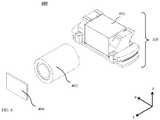
- FIGS. 1A-Fshow schematically various views and components of an exemplary embodiment of a rotational ball-guided VCM actuator disclosed herein and numbered 100 .
- VCM actuatoror just “actuator” will replace the term “rotational ball-guided VCM actuator” in the description hereinbelow.
- FIG. 1Ashows actuator 100 in an isomeric view
- FIG. 1Bshows actuator 100 in an exploded view.
- Actuator 100allows tilting of an optical path folding element (OPFE) 150 around a single axis (exemplarily and as shown, axis X), as further described below.
- OPFE 150folds light from a first optical axis (aligned with Z) to a second optical axis (aligned with Y).
- OPFEoptical path folding element
- OPFE 150is exemplarily a prism.
- the OPFEmay be, for example, a mirror or a lens.
- Actuator 100has exemplary length/width/height dimensions in the range of 5-15 mm, i.e. actuator 100 can be contained in a box with dimension of 5 ⁇ 5 ⁇ 5 mm 3 to 15 ⁇ 15 ⁇ 15 mm 3 .
- the descriptioncontinues with reference to a coordinate system XYZ shown in FIGS. 1A and 1B as well as in a number of other figures.
- OPFE 150may be held in an optical element holder 102 , which can be made, for example, by a plastic mold that fits the shape of element OPFE 150 .
- a permanent (fixed) magnet 104is fixedly attached (e.g. glued) to optical element holder 102 from below (negative Z direction in the FIG. 1A ).
- the term “below” used with reference to an OPFEe.g. prism
- OPFE 150 , optical element holder 102 and magnet 104form an “actuated sub-assembly” 106 .
- Actuated sub-assembly 106is shown from a bottom view in FIG. 1C .
- FIG. 1Dshows a cross section of actuator 100 along a line A-A marked in FIG. 1A .
- FIG. 1Eshows details of an electro-magnetic (EM) sub-assembly of actuator 100 .
- FIG. 1Fshows a cross section of actuator 100 along a line B-B marked in FIG. 1A .
- Optical element holder 102includes (i.e. is molded with) two parallel arc-shaped (or “curved”) grooves 102 a and 102 b ( FIG.
- each arc-shaped groovehaving an angle ⁇ ′> ⁇ , where angle ⁇ is a required tilt stroke, as defined by optical needs.
- Angle ⁇ ′is shown in FIG. 1D .
- Arc-shaped grooves 102 a and 102 bhave a center of curvature on a common rotation axis 108 ( FIG. 1D ).
- axis 108 from grooves 102 a and 102 bis typically 2-15 mm. As such axis 108 may pass through (be internal to) OPFE 150 or outside of (be external to) OPFE 150 , see also FIG. 1K .
- OISoptical image stabilization
- ⁇may exemplarily be in the range 0.25° ⁇ 2°.
- FOVTele field of view
- ⁇may exemplarily be in the range 2° ⁇ 12°.
- ⁇ ′is greater than ⁇ by about 0.5°.
- Actuator 100further includes a base 110 , typically made of plastic.
- Base 110is also molded with two arc-shaped grooves 110 a and 110 b positioned at two opposite sides of base 110 , each arc-shaped groove ( 110 a and 110 b ) having an angle ⁇ ′′> ⁇ .
- Angle ⁇ ′′is also shown in FIG. 1D .
- ⁇ ′′is greater than ⁇ by about 0.5°.
- Arc-shaped grooves 110 a and 110 balso have a center of curvature on axis 108 ( FIG. 1D ).
- Actuated sub-assembly 106is positioned inside base 110 such that grooves 110 a and 110 b are parallel to and adjacent to grooves 102 a and 102 b respectively, and the centers of curvature for each couple of grooves are concentric respectively with axis 108 .
- optical element holder 102 and base 110are preferably plastic-molded (although they may also be made of aluminum or other metals) there is some tolerance allowed in part dimensions, typically up to a few tens of microns for each dimension. This tolerance may lead to misalignment of position between adjacent grooves 102 a - 110 a and/or 102 b - 110 b .
- grooves 102 a , 110 a and 110 bhave what is known in the art as a (non-limiting) ‘V’-groove cross-section shape to match the balls, while groove 102 b has a cross-section which is wider and has a (non-limiting) ‘trapezoid’ cross-section.
- Grooves 102 a and 110 aare then aligned during assembly, while grooves 102 b and 110 b have some alignment freedom allowed by the trapezoid cross section.
- all grooves ( 102 a , 102 b , 110 a , and 110 b )may have a V-shape.
- actuator 100three balls 112 a , 114 a and 116 a are positioned in the space between grooves 102 a and 110 a and three balls 112 b , 114 b and 116 b are positioned in the space between grooves 102 b and 110 b .
- the number of balls(here 3) is exemplary.
- a disclosed VCM actuatormay have more or less of three balls (e.g. 2-7 balls) in the space between adjacent grooves.
- the ballsare typically made of Alumina or another ceramic material, but may also be made of metal, plastic or other materials.
- the ballshave a typical diameter in the range of 0.3-1 mm.
- a distance L between grooves 102 a,b and grooves 110 a,b (and their respective sets of balls)is larger than a width W of OPFE 150 , such that the grooves and balls are “outside” of OPFE 150 with respect to the X axis.
- grooves 102 a , 102 b , 110 a , 110 b and balls 112 a , 112 b , 114 a , 114 b , 116 a and 116 bform a curved ball-guided mechanism 160 operative to impart a rotation or tilt movement to an optical element (e.g. OPFE 150 ) upon actuation by the VCM actuator (see FIG. 1K )
- an optical elemente.g. OPFE 150
- two different ball sizesmay be used to provide smoother motion.
- the ballscan be divided into a large diameter (LD) group and a small diameter (SD) group.
- the balls in each grouphave the same diameter.
- LD ballsmay have for example a 0.1-0.3 mm larger diameter than SD balls.
- a SD ballmay be positioned between two LD balls to maintain the rolling ability of the mechanism.
- balls 112 a and 116 amay be LD balls and ball 114 a may be a SD ball.
- a metallic ferromagnetic yoke 118is fixedly attached (e.g. glued) to base 110 from below (negative Z direction in the FIG. 1B ), such that it faces magnet 104 .
- the yoke 118pulls magnet 104 (and thus pulls the actuated sub-assembly 106 ) by magnetic force and thus holds the curved ball-guided mechanism from coming apart.
- the magnetic forceis in a direction marked in FIGS. 1A-C as the negative Z direction.
- Balls 112 a , 114 a and 116 a and balls 112 b , 114 b and 116 bprevent actuated sub-assembly 106 from touching the base.
- Actuated sub-assembly 106is thus confined along the Z-axis and does not move in positive or negative Z directions.
- Curved ball-guided mechanism 160further confines the actuated sub-assembly along the X-axis, and thus the actuated sub-assembly can only move along the path defined by the parallel arc-shaped grooves 102 a , 102 b , 110 a and 110 b.
- Actuator 100further includes an EM sub-assembly 120 , FIG. 1E .
- Electro-magnetic sub-assembly 120includes a coil 122 , a position sensor, for example a Hall bar element 124 and a printed circuit board (PCB) 126 .
- Coil 122 and Hall bar element 124are preferably soldered (each on its own) to PCB 126 .
- Coil 122has a stadium (oval) shape, and typically has a few tens of windings (e.g. but not limited to 50-250), and a typical resistance of 10-30 ohm.
- PCB 126allows sending input and output currents to coil 122 and Hall bar element 124 . The currents carry both power and electronic signals needed for operation.
- PCB 126is connected electronically to a camera (e.g. a camera as in FIG. 2 ) which actuator 100 is part of, using wires (not shown).
- Electro-magnetic sub-assembly 120is positioned between magnet 104 and yoke 118 .
- Driving a current in coil 122creates a Lorentz force: a current in a clockwise direction will create force in the positive Y direction, while a current in counter clockwise direction will create a force in the negative Y direction.
- the full magnetic scheme(e.g. fixed magnet 104 pole direction) is known in the art and described for example in detail in co-owned patent PCT/IB2016/052179.
- Hall bar element 124can sense the intensity and direction of the magnetic field of magnet 104 .
- the relative position of actuated sub-assembly 106 and Hall bar element 124is changed.
- the intensity and direction of the magnetic field sensed by Hall bar element 124change as well, and thus the position of actuated sub-assembly 106 can be determined.
- a control circuitis used to control the position of the actuated sub-assembly and to set it to the position required by optical demands.
- the control circuit inputis a signal from Hall bar element 124 and the output is the amount of current applied in coil 122 .
- the control circuitmay be implemented in an integrated circuit (IC). In some cases the IC may be combined with Hall element 124 . In other cases, the IC may be a separate chip (not shown), which can be located outside of actuator 100 and of a camera including actuator 100 (e.g. see below embodiment 200 ).
- FIGS. 1G-1Jshow schematically various views and components of another exemplary embodiment of a VCM actuator disclosed herein and numbered 100 ′.
- FIG. 1Gshows actuator 100 in an isomeric view
- FIG. 1Hshows actuator 100 in an exploded view
- FIG. 1Ishows details of an actuated sub-assembly 106 ′ in the actuator of FIG. 1G
- FIG. 1Jshows a cross section of the VCM actuator along a line B-B marked in FIG. 1G .
- Actuator 100 ′is similar to actuator 100 in structure (and therefore similar elements/components are not numbered and/or described) and function except for a few differences: a) actuator 100 ′ includes three V-shaped grooves and one flat groove, i.e.
- actuator 100 ′optical element holder 102 is replaced by an optical element holder 102 ′ in which groove 102 b ′ is flat; b) in actuator 100 ′, a distance L′ between grooves 102 a,b and grooves 110 a,b (and their respective sets of balls) is equal to or smaller than a width W′ of OPFE 150 , such that the grooves and balls are “below” OPFE 150 .
- actuator 100 ′includes an added component, a shield 140 , which protect it from drops, hits, dust and stray light.
- shield 140is such as to minimally affect the size of the actuator.
- the shape and details shownare exemplary.
- a shieldsuch a shield 140 may also be provided for actuator 100 .
- actuator 100 ′also includes an enclosure 142 (normally made of plastic) to protect the actuator against environmental and other factors.
- PCB 126 ′has the same function as PCB 126 in actuator 100 .
- a curved ball-guided mechanism in actuator 100 ′includes essentially the same components as in actuator 100 .
- FIG. 1 Kshows in addition to shape embodiments “a” and “b” (axis 108 external or internal to OPFE 150 , with both grooves 102 and 110 of a pair curved “downwards”, i.e.
- FIG. 2shows actuator 100 coupled to folded camera structure (FCS) or simply “folded camera” 200 .
- an actuatorsuch as 100 (or 100 ′) serves for example to rotate a light folding element, for example prism 150 .
- Actuation by actuator 100 in folded camera 200can be used, for example, to create optical image stabilization (OIS) as described in PCT/IB2016/052179 or to create an extended field of view, as described for example in PCT/IB2016/057366.
- a typical rotational stroke ⁇ in this casemay be in the range of ⁇ 0.5 to ⁇ 2 degrees or ⁇ 2 to ⁇ 12 degrees of the original position of prism 150 respectively.
- Camera 200further includes a lens element 202 and an image sensor 204 .
- Folded camera 200may further be coupled to or include actuation mechanisms to actuate lens element 204 for AF and ⁇ or OIS, for example described in PCT/IB2016/052179.
- the actuation mechanisms (and actuations) of lens 204are independent of those of actuator 100 and are not shown in FIG. 2 .
- the actuation mechanisms (and actuations) of lens 204may be based on a VCM actuator with mechanical rails based on springs (as in PCT/IB2016/052179) or with mechanical rails based on a ball-guided mechanism.
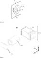
- FIGS. 3A-Dshows schematically various views and components of another exemplary embodiment of a VCM actuator disclosed herein and numbered 300 .
- FIG. 3Ashows actuator 300 in an isomeric view
- FIG. 3Bshows actuator 300 in an exploded view.
- an OPFE 350is exemplarily a prism.
- OPFE 350is held in an optical element holder 302 .
- a permanent magnet 304is fixedly attached (e.g. glued) to optical element holder 302 .
- OPFE 350 , optical element holder 302 and magnet 304form a “top actuated sub-assembly” 306 .
- Optical element holder 302includes (e.g. is molded with) two parallel arc-shaped grooves 302 a and 302 b positioned at two opposite sides of holder 302 , each arc-shaped groove having an angle ⁇ ′> ⁇ , where angle ⁇ is a required rotational stroke, as defined by optical needs. Angles ⁇ ′ and ⁇ ′′ are not shown, but its definition is similar to that of angles ⁇ ′ and ⁇ ′′ in FIG. 1D . Exemplary values and ranges for ⁇ , ⁇ ′ and ⁇ ′′ are similar to those for ⁇ , ⁇ ′ and ⁇ ′′ above. Top actuated sub-assembly 306 and its parts are similar to actuated sub-assembly 106 in terms of materials, dimensions, etc.
- Actuator 300further includes a middle base 310 , typically made of plastic.
- Middle base 310is also molded with two grooves 310 a and 310 b .
- Top-actuated sub-assembly 306is positioned inside middle base 310 such that grooves 310 a and 310 b are parallel to grooves 302 a and 302 b respectively.
- grooves 302 b , 310 a and 310 bhave V-groove shape, while groove 302 a has a trapezoid shape; the considerations for these shapes was given above in the description of actuator 100 .
- Middle base 310further includes two more arc-shaped grooves 310 c and 310 d on a single circle 320 , as seen in FIG. 3C .
- Top actuated sub-assembly 306 , balls 312 a - 314 a , 312 b - 314 b and middle base 310form a bottom actuated sub-assembly 334 .
- the diameter of circle 320may exemplarily be in the range of 5-15 mm.
- Grooves 302 a , 302 b , 310 a , 310 b and balls 312 a , 312 b , 314 a , 314 b , 316 a and 316 bform a first curved ball-guided mechanism 360 of actuator 300 .
- Actuator 300further includes a bottom base 308 .
- Bottom base 308is typically made of plastic, and is molded with two arc-shaped grooves 308 c and 308 d .
- Arc-shaped grooves 308 c and 308 dare on circle 320 with a center on an axis 321 , as can be seen in FIG. 3C .
- Bottom actuated sub-assembly 334is positioned above bottom base 308 such that grooves 310 c and 310 d are parallel to grooves 308 c and 308 d respectively.
- grooves 310 c , 308 c , 308 dhave V-groove shape, while groove 310 d has a trapezoid shape; the considerations for these shapes were given above in the description of actuator 100 .
- Three balls 312 c , 314 c and 316 care positioned between grooves 308 c and 310 c , and similarly three balls 312 d , 314 d and 316 d are positioned between grooves 308 d and 310 d .
- actuator 300may have more or less of 3 balls in each groove, typically in the range of 2-7. The considerations for size and materials of all balls are similar to those described in actuator 100 .
- Grooves 308 c , 308 d , 310 c , 310 d and balls 312 c , 312 d , 314 c , 314 d , 316 c and 316 dform a second curved ball-guided mechanism 362 of actuator 300 .
- a metallic yoke 318is fixedly attached (e.g. glued) to bottom base 308 from below, such that it faces magnet 304 .
- Metallic yoke 318pulls magnet 304 (and thus pulls top actuated sub-assembly 306 ) by magnetic force and thus holds the two curved ball-guided mechanisms ( 360 and 362 ) from coming apart.
- the magnetic forceis in direction marked in FIG. 1 as the negative Z direction.
- Balls 312 a , 314 a and 316 a and 312 b , 314 b and 316 bprevent top actuated sub-assembly 306 from touching middle base 310 , and balls 312 c , 314 c and 316 c and 312 d , 314 d and 316 d prevent bottom actuated sub-assembly 334 from touching bottom base 308 .
- Top actuated sub-assembly 306is thus confined along the Z-axis and does not move in positive or negative Z directions.
- First curved ball-guided mechanism 360further confines top actuated sub-assembly 306 along the X-axis, and thus top actuated sub-assembly 306 can only move along the path defined by the parallel arcs 302 a , 302 b , 310 a and 310 b .
- Bottom actuated sub-assembly 334is confined along the Z-axis and does not move in positive or negative Z directions.
- Second curved ball-guided mechanism 362further confines bottom actuated sub-assembly 334 to move only in a rotational manner around circle 320 (rotation around the Z-axis). The typical magnitude/angle of this rotation (in degrees) is similar to that of a above.
- Magnet 304acts on both curved ball-guiding mechanism.
- Actuator 300further includes an electro-magnetic sub-assembly 330 , shown in FIG. 3D .
- Electro-magnetic sub-assembly 330includes two coils 322 and 324 , two Hall bar elements 326 and 328 and a printed circuit board (PCB) 329 .
- Coils 322 , 324 and Hall bar elements 326 , 328are soldered (each one on its own) to PCB 329 .
- Coils 322 , 324have a stadium shape, typically with a few tens of windings (for example, in a non-limiting range of 50-250), with a typical resistance 10-30 ohm each.
- PCB 329allows sending input and output currents to coils 322 , 324 and to Hall bar elements 326 , 328 , currents carrying both power and electronic signals needed for operation.
- PCB 329is connected electronically to the external camera with wires not seen in FIG. 3 .
- Electro-magnetic sub-assembly 330is positioned between magnet 304 and yoke 318 .
- a Lorentz forceis created; a current in a clockwise direction will create force in the positive Y direction while a current in a counter clockwise direction will create a force in the negative Y direction.
- the full magnetic scheme(e.g. fixed magnet 304 pole direction) is similar to that in actuator 100 .
- the Lorentz forceis also translated to clockwise (counter clockwise) torque around Z axis on bottom actuated sub-assembly 334 .
- top actuated sub-assembly 306is confined by the first curved ball-guided mechanism to move along an arc parallel to grooves 302 a , 302 b , 310 a and 310 b (i.e. rotate around the X axis).
- bottom actuated sub-assembly 334is confined by the second curved ball-guided mechanism to move around circle 320 (i.e.
- Hall bar elements 326 , 328can sense the intensity and direction of the magnetic field of magnet 304 .
- the position of top actuated sub-assembly 306 , bottom actuated sub-assembly 334 and Hall bar elements 326 , 328is changed, and with it changes the intensity and direction of the magnetic field sensed.
- V HB-326 and V HB-328the Hall output voltage of both sensors, which is proportional to the magnetic field sensed by each Hall sensor, as known in the art.
- the amount of rotation of top actuated sub-assembly 306 and bottom actuated sub-assembly 334can be determined.
- the sum V HB-326 +V HB-328is proportional to the amount of tilt around the first rotation axis and the difference V HB-326 -V HB-328 is proportional to the amount of tilt around the second rotation axis.
- a control circuitis used to control the position of the actuated sub-assembly and to set it to the position required by optical demands.
- the control circuit inputincludes signals of Hall bar elements 326 , 328 and the output includes the amount of current applied in coils 322 , 324 .
- the control circuitmay be implemented in an integrated circuit (IC). In some cases, the IC may be combined with one of Hall elements 326 , 328 . In other cases, the IC is a separate chip, which can be located outside of the camera (not shown).
- FIG. 4shows actuator 300 as part of a folded camera 400 .
- actuator 300serves for example to rotate an optical path folding element (OPFE) to create optical image stabilization in two directions, as described for example in U.S. provisional patent application 62/215,007.
- Folded camera 400further includes a lens element 402 and an image sensor 404 .
- a typical actuation stroke in this casemay be in the range of ⁇ 0.5 to ⁇ 2 degrees around the X axis and ⁇ 1 to ⁇ 3 degrees around the Z axis of the original position of the light-folding element (e.g. prism 450 ) for both rotation directions.
- OPFEoptical path folding element
- Folded camera 400may further include an actuation mechanism (not shown) for lens element 402 as known in the art (for example described in PCT/IB2016/052179) for AF and/or OIS.
- the actuation mechanism of lens 402is not dependent on the actuation done in actuator 300 .
- FIGS. 5A-5Dshow schematically various views and components of another exemplary embodiment of a VCM actuator disclosed herein and numbered 500 .
- FIG. 5Ashows an isomeric view of an assembled actuator 500
- FIGS. 5B, 5Cshow an exploded view of actuator 500 from two opposite directions along the X-axis.
- FIG. 5Dshows a cross section of actuator 500 along a line A-A marked in FIG. 5A .
- Actuator 500allows the rotation of an OPFE 550 around a single axis (i.e. around the X-axis) as described below.
- OPFE 550is a prism while in other embodiments it may a mirror or another type of optical path bending element.
- OPFE 550is held in an OPFE holder 502 , which can be made, for example by plastic mold, fitting the shape of OPFE 550 .
- An actuation magnet 504 and a sensing magnet 506are fixedly attached (e.g. glued) to optical element holder 502 from the side, in the same direction as an axis of rotation of OPFE 550 (the negative X direction in the figures).
- the assembly of OPFE 550 , optical element holder 502 and magnets 504 , 506is referred to as “actuated sub-assembly” 510 , shown from the side in FIG. 5D .
- Optical element holder 502is molded with two arc-shaped grooves, 502 a and 502 b .
- Arcs 502 a and 502 bare concentric with each other, having a common center of rotation on an axis 508 .
- Arc-shaped grooves 502 a and 502 bhave respective angles ⁇ ′ and ⁇ ′′ fulfilling ⁇ ′> ⁇ and ⁇ ′′> ⁇ , where angle ⁇ is the required rotational stroke, as defined by optical needs.
- the center of rotation axis 508 and angles ⁇ ′, ⁇ ′′are seen in FIG. 5D .
- the typical values for ⁇ , ⁇ ′ and ⁇ ′′are similar to those for ⁇ , ⁇ ′ and ⁇ ′′.
- Actuator 500further includes a sidewall 514 .
- Sidewall 514is a stationary part and is fixed rigidly to the actuator frame (not shown) and to the camera image sensor.
- Sidewall 514is typically made of plastic.
- sidewall 514may be a part of the entire actuator's frame (known in the art as ‘base’).
- Sidewall 514may be molded as a single piece of plastic which serves for the purposes described below, as well as other purposes needed for the camera which actuator 500 is part of (e.g. holding the lens or holding the image sensor).
- Sidewall 514is also molded with two arc-shaped grooves 514 a and 514 b .
- Actuated sub-assembly 510is positioned alongside sidewall 514 such that grooves 514 a and 514 b are parallel to grooves 502 a and 502 b respectively.
- grooves 502 b , 514 a and 514 bhave V-groove shape, while groove 502 a has a trapezoid shape; the considerations for these shapes was given above in the description of actuator 100 .
- actuator 500may have more or less than 3 balls in each groove, typically in the range of 2-7 balls. Consideration for size and materials of all balls is similar to the described in actuator 100 .
- the two pairs of grooves and their associated ballsform a curved ball-guided mechanism 560 of actuator 500 .
- a metallic ferromagnetic yoke 518is fixedly attached (e.g. glued) to sidewall 514 from a side opposite to those of magnets 504 , 506 such that it faces magnet 504 .
- Yoke 518pulls magnet 504 (and thus pulls the actuated sub-assembly 510 ) by magnetic force and thus holds the curved ball-guided mechanism from coming apart.
- the magnetic forceis in direction marked in FIG. 5A as the negative X direction.
- Balls 512 a , 514 a and 516 a and 512 b , 514 b and 516 bprevent actuated sub-assembly 510 from touching sidewall 514 .
- Actuated sub-assembly 510is thus confined along the X-axis and does not move in positive or negative X directions.
- Curved ball-guided mechanism 560further confines the actuated sub-assembly 510 along other directions such that actuated sub-assembly can only move along the path defined by the parallel arcs 502 a , 502 b , 514 a and 514 b
- Actuator 500further includes an electro-magnetic sub-assembly 530 , shown in FIG. 5E .
- Electro-magnetic sub-assembly 530includes a coil 522 , a Hall bar element 524 and a PCB 526 .
- Coil 522 and Hall bar element 524are soldered (each one by its own) to the PCB.
- Coil 522has a stadium shape, typically has few tens of winding (not limiting range of 50-250), with a typical resistance of 10-30 ohm.
- PCB 526allows sending input and output currents to coil 522 and Hall bar element 524 , currents carrying both power and electronic signals needed for operation.
- PCB 526is connected electronically to the external camera with wires (not shown).
- Electro-magnetic sub-assembly 530is positioned between the magnets 504 , 506 and yoke 518 such that there is an air-gap of typically about 100-200 ⁇ m between the magnets and the electro-magnetic sub-assembly (the Hall bar element, coil and magnets do not touch each other).
- a Lorentz forceis created: a current in a clockwise direction will create force in the positive Y direction while a current in counter clockwise direction will create a force in the negative Y direction.
- the full magnetic scheme(e.g. the fixed magnet 504 pole direction) is known in the art, and described for example in detail in co-owned patent PCT/IB2016/052179.
- Hall bar element 524can sense the intensity and direction of the magnetic field of sensing magnet 506 .
- the relative position of actuated sub-assembly 510 and Hall bar element 524is changed.
- the intensity and direction of the magnetic field senses by Hall bar element 524changes as well and thus the position of actuated sub-assembly 510 can be determined.
- a control circuitis used to control the position of the actuated sub-assembly and set to the position required by optical demands.
- the control circuit inputis a signal from Hall bar element 524 and the output is the amount of current applied in coil 522 .
- the control circuitmay be implemented in an IC. In some cases, the IC may be combined with Hall element 524 . In other cases, it is a separate chip, which can be located outside of the camera (not shown).
- the sensing magnet 506can be removed and the Hall bar element 524 can be placed in the center of the coil so the actuation magnet 504 can be used for both actuation and sensing (as described for example above with reference to FIG. 1E ).
- sensing magnet 506 and actuation magnet 504may be combined into one magnet with the suitable magnetization to allow the sensing and actuating functionality described above.
- FIG. 6shows actuator 500 as part of a folded camera 600 .
- actuator 500serves as an example of usage to rotate a light folding element, for example prism 550 .
- Actuation by actuator 500 in camera 600can be used, for example, to create OIS as described in PCT/IB2016/052179.
- Camera 600further includes a lens element 602 and an image sensor 604 .
- a typical actuation stroke ⁇ in this caseshould be in the range of ⁇ 0.5 to ⁇ 2 degrees of the original position of prism 550 .
- camera 600may further include actuation mechanisms to actuate lens element 602 for AF and ⁇ or OIS (not shown).
- any of the actuators disclosed abovemay be included in a folded camera which in turn may be included together with an upright (non-folded) camera in a dual-aperture camera with folded lens, for example as described in co-owned U.S. Pat. No. 9,392,188.
Landscapes
- Physics & Mathematics (AREA)
- General Physics & Mathematics (AREA)
- Engineering & Computer Science (AREA)
- Optics & Photonics (AREA)
- Multimedia (AREA)
- Signal Processing (AREA)
- Power Engineering (AREA)
- Chemical & Material Sciences (AREA)
- Combustion & Propulsion (AREA)
- Electromagnetism (AREA)
- Microelectronics & Electronic Packaging (AREA)
- Adjustment Of Camera Lenses (AREA)
- Studio Devices (AREA)
- Reciprocating, Oscillating Or Vibrating Motors (AREA)
Abstract
Description
Claims (19)
Priority Applications (4)
| Application Number | Priority Date | Filing Date | Title |
|---|---|---|---|
| US16/154,093US11150447B2 (en) | 2016-05-30 | 2018-10-08 | Rotational ball-guided voice coil motor |
| US17/367,382US11650400B2 (en) | 2016-05-30 | 2021-07-04 | Rotational ball-guided voice coil motor |
| US18/309,814US11977210B2 (en) | 2016-05-30 | 2023-04-30 | Rotational ball-guided voice coil motor |
| US18/626,442US12372758B2 (en) | 2016-05-30 | 2024-04-04 | Rotational ball-guided voice coil motor |
Applications Claiming Priority (5)
| Application Number | Priority Date | Filing Date | Title |
|---|---|---|---|
| US201662343011P | 2016-05-30 | 2016-05-30 | |
| US201662353278P | 2016-06-22 | 2016-06-22 | |
| US15/559,039US10488631B2 (en) | 2016-05-30 | 2017-04-25 | Rotational ball-guided voice coil motor |
| PCT/IB2017/052383WO2017208090A1 (en) | 2016-05-30 | 2017-04-25 | Rotational ball-guided voice coil motor |
| US16/154,093US11150447B2 (en) | 2016-05-30 | 2018-10-08 | Rotational ball-guided voice coil motor |
Related Parent Applications (2)
| Application Number | Title | Priority Date | Filing Date |
|---|---|---|---|
| US15/559,039ContinuationUS10488631B2 (en) | 2016-05-30 | 2017-04-25 | Rotational ball-guided voice coil motor |
| PCT/IB2017/052383ContinuationWO2017208090A1 (en) | 2016-05-30 | 2017-04-25 | Rotational ball-guided voice coil motor |
Related Child Applications (1)
| Application Number | Title | Priority Date | Filing Date |
|---|---|---|---|
| US17/367,382ContinuationUS11650400B2 (en) | 2016-05-30 | 2021-07-04 | Rotational ball-guided voice coil motor |
Publications (2)
| Publication Number | Publication Date |
|---|---|
| US20190049687A1 US20190049687A1 (en) | 2019-02-14 |
| US11150447B2true US11150447B2 (en) | 2021-10-19 |
Family
ID=60479293
Family Applications (5)
| Application Number | Title | Priority Date | Filing Date |
|---|---|---|---|
| US15/559,039Active2037-08-10US10488631B2 (en) | 2016-05-30 | 2017-04-25 | Rotational ball-guided voice coil motor |
| US16/154,093Active2038-08-17US11150447B2 (en) | 2016-05-30 | 2018-10-08 | Rotational ball-guided voice coil motor |
| US17/367,382Active2037-08-31US11650400B2 (en) | 2016-05-30 | 2021-07-04 | Rotational ball-guided voice coil motor |
| US18/309,814ActiveUS11977210B2 (en) | 2016-05-30 | 2023-04-30 | Rotational ball-guided voice coil motor |
| US18/626,442ActiveUS12372758B2 (en) | 2016-05-30 | 2024-04-04 | Rotational ball-guided voice coil motor |
Family Applications Before (1)
| Application Number | Title | Priority Date | Filing Date |
|---|---|---|---|
| US15/559,039Active2037-08-10US10488631B2 (en) | 2016-05-30 | 2017-04-25 | Rotational ball-guided voice coil motor |
Family Applications After (3)
| Application Number | Title | Priority Date | Filing Date |
|---|---|---|---|
| US17/367,382Active2037-08-31US11650400B2 (en) | 2016-05-30 | 2021-07-04 | Rotational ball-guided voice coil motor |
| US18/309,814ActiveUS11977210B2 (en) | 2016-05-30 | 2023-04-30 | Rotational ball-guided voice coil motor |
| US18/626,442ActiveUS12372758B2 (en) | 2016-05-30 | 2024-04-04 | Rotational ball-guided voice coil motor |
Country Status (5)
| Country | Link |
|---|---|
| US (5) | US10488631B2 (en) |
| EP (3) | EP3518520B1 (en) |
| KR (2) | KR102002718B1 (en) |
| CN (2) | CN107925717B (en) |
| WO (1) | WO2017208090A1 (en) |
Cited By (1)
| Publication number | Priority date | Publication date | Assignee | Title |
|---|---|---|---|---|
| US12003835B2 (en) | 2019-07-23 | 2024-06-04 | Lg Innotek Co., Ltd. | Camera actuator |
Families Citing this family (133)
| Publication number | Priority date | Publication date | Assignee | Title |
|---|---|---|---|---|
| CN112911252B (en) | 2012-11-28 | 2023-07-04 | 核心光电有限公司 | Multi-aperture imaging system |
| KR101634516B1 (en) | 2013-06-13 | 2016-06-28 | 코어포토닉스 리미티드 | Dual aperture zoom digital camera |
| US9857568B2 (en) | 2013-07-04 | 2018-01-02 | Corephotonics Ltd. | Miniature telephoto lens assembly |
| JP2016523389A (en) | 2013-07-04 | 2016-08-08 | コアフォトニクス リミテッド | Compact telephoto lens assembly |
| CN108989649B (en) | 2013-08-01 | 2021-03-19 | 核心光电有限公司 | Slim multi-aperture imaging system with autofocus and method of use |
| US9392188B2 (en) | 2014-08-10 | 2016-07-12 | Corephotonics Ltd. | Zoom dual-aperture camera with folded lens |
| CN112433331B (en) | 2015-01-03 | 2022-07-08 | 核心光电有限公司 | Miniature telephoto lens module and camera using the same |
| CN112394467B (en) | 2015-04-16 | 2023-06-09 | 核心光电有限公司 | Autofocus and Optical Image Stabilization in a Compact Folding Camera |
| US10230898B2 (en) | 2015-08-13 | 2019-03-12 | Corephotonics Ltd. | Dual aperture zoom camera with video support and switching / non-switching dynamic control |
| KR102369223B1 (en) | 2015-12-29 | 2022-03-02 | 코어포토닉스 리미티드 | Dual-aperture zoom digital camera with automatic adjustable tele field of view |
| CN116661090A (en) | 2016-05-10 | 2023-08-29 | 台湾东电化股份有限公司 | lens system |
| KR102002718B1 (en) | 2016-05-30 | 2019-10-18 | 코어포토닉스 리미티드 | Rotary Ball-Guid Voice Coil Motor |
| KR20240036133A (en) | 2016-06-19 | 2024-03-19 | 코어포토닉스 리미티드 | Frame synchronization in a dual-aperture camera system |
| KR20240051317A (en) | 2016-07-07 | 2024-04-19 | 코어포토닉스 리미티드 | Linear ball guided voice coil motor for folded optic |
| KR101862228B1 (en)* | 2016-10-05 | 2018-05-30 | 자화전자(주) | Apparatus for driving optical-reflector for ois |
| EP3842853B1 (en) | 2016-12-28 | 2024-03-06 | Corephotonics Ltd. | Folded camera structure with an extended light-folding-element scanning range |
| US10884321B2 (en) | 2017-01-12 | 2021-01-05 | Corephotonics Ltd. | Compact folded camera |
| KR102089288B1 (en)* | 2017-02-07 | 2020-04-23 | 자화전자(주) | Apparatus for supporting optical reflector |
| US10678062B2 (en) | 2017-02-08 | 2020-06-09 | Samsung Electro-Mechanics Co., Ltd. | Reflecting module for optical image stabilization (OIS) and camera module including the same |
| KR102072810B1 (en)* | 2017-02-08 | 2020-02-03 | 삼성전기주식회사 | Camera module and portable electronic device including the same |
| EP3584624B1 (en)* | 2017-02-20 | 2021-07-21 | Jahwa Electronics Co., Ltd. | Reflection system driving device having multi-axis structure |
| KR102166942B1 (en)* | 2017-02-20 | 2020-10-16 | 자화전자(주) | Apparatus for driving optical-reflector for ois with multi-axisal structure |
| KR102530535B1 (en) | 2017-03-15 | 2023-05-08 | 코어포토닉스 리미티드 | Cameras with panoramic scanning range |
| JP6997370B2 (en)* | 2017-05-25 | 2022-01-17 | ミツミ電機株式会社 | Camera actuators, camera modules, and camera-mounted devices |
| WO2019048904A1 (en) | 2017-09-06 | 2019-03-14 | Corephotonics Ltd. | Combined stereoscopic and phase detection depth mapping in a dual aperture camera |
| US10951834B2 (en) | 2017-10-03 | 2021-03-16 | Corephotonics Ltd. | Synthetically enlarged camera aperture |
| US10462370B2 (en) | 2017-10-03 | 2019-10-29 | Google Llc | Video stabilization |
| US11333955B2 (en) | 2017-11-23 | 2022-05-17 | Corephotonics Ltd. | Compact folded camera structure |
| CN114609746A (en) | 2018-02-05 | 2022-06-10 | 核心光电有限公司 | Folding camera device |
| KR102219453B1 (en)* | 2018-02-08 | 2021-02-24 | 자화전자(주) | Apparatus for driving optical system with memory unit |
| KR102423689B1 (en)* | 2018-02-08 | 2022-07-21 | 자화전자(주) | Apparatus for driving optical system with memory unit |
| CN113568251B (en) | 2018-02-12 | 2022-08-30 | 核心光电有限公司 | Digital camera and method for providing focus and compensating for camera tilt |
| KR102497828B1 (en)* | 2018-02-23 | 2023-02-08 | 엘지이노텍 주식회사 | Camera module |
| US10694168B2 (en) | 2018-04-22 | 2020-06-23 | Corephotonics Ltd. | System and method for mitigating or preventing eye damage from structured light IR/NIR projector systems |
| KR20250053984A (en)* | 2018-04-23 | 2025-04-22 | 코어포토닉스 리미티드 | An optical-path folding-element with an extended two degree of freedom rotation range |
| US10171738B1 (en) | 2018-05-04 | 2019-01-01 | Google Llc | Stabilizing video to reduce camera and face movement |
| KR102581599B1 (en)* | 2018-05-11 | 2023-09-25 | 엘지전자 주식회사 | Prism module, camera, and image display apparatus including the same |
| WO2019216681A1 (en)* | 2018-05-11 | 2019-11-14 | 엘지전자 주식회사 | Prism module, camera comprising same, and image display device |
| KR102662948B1 (en) | 2018-05-21 | 2024-05-07 | 엘지전자 주식회사 | Camera, and terminal including the same |
| US11019242B2 (en)* | 2018-06-14 | 2021-05-25 | Guangdong Oppo Mobile Telecommunications Corp., Ltd. | Camera assembly and electronic device using the same, both having a decorative member mounted on a shell and comprising a decorative ring and a flange |
| CN108449540B (en)* | 2018-06-15 | 2020-07-10 | Oppo广东移动通信有限公司 | Camera module, camera assembly and electronic device |
| CN119919618A (en) | 2018-07-04 | 2025-05-02 | 核心光电有限公司 | Cameras with folded scanning beam path for automotive or surveillance applications |
| CN108965663B (en)* | 2018-07-09 | 2020-07-03 | Oppo广东移动通信有限公司 | electronic device |
| EP3817357B1 (en)* | 2018-07-09 | 2023-05-10 | Guangdong Oppo Mobile Telecommunications Corp., Ltd. | Camera module, assembly, electronic device, mobile terminal, and photography method |
| CN108810386A (en)* | 2018-08-02 | 2018-11-13 | Oppo广东移动通信有限公司 | Camera module, CCD camera assembly and electronic device |
| KR102723559B1 (en) | 2018-08-02 | 2024-10-30 | 엘지이노텍 주식회사 | Lens Actuator and Camera module including the same |
| CN108777761B (en)* | 2018-08-02 | 2024-04-02 | Oppo广东移动通信有限公司 | Imaging modules and electronic devices |
| CN111316346B (en) | 2018-08-04 | 2022-11-29 | 核心光电有限公司 | Switchable continuous display information system above camera |
| US11635596B2 (en) | 2018-08-22 | 2023-04-25 | Corephotonics Ltd. | Two-state zoom folded camera |
| EP3674768B1 (en)* | 2018-12-27 | 2023-09-20 | Tdk Taiwan Corp. | Optical member driving mechanism |
| JP7554753B2 (en)* | 2018-12-28 | 2024-09-20 | オプトチューン スウィツァランド アーゲー | Tiltable folding mirror for optical imaging systems - Patents.com |
| US11336830B2 (en) | 2019-01-03 | 2022-05-17 | Corephotonics Ltd. | Multi-aperture cameras with at least one two state zoom camera |
| US11287081B2 (en) | 2019-01-07 | 2022-03-29 | Corephotonics Ltd. | Rotation mechanism with sliding joint |
| CN109633854B (en)* | 2019-01-08 | 2020-09-29 | 瑞声通讯科技(常州)有限公司 | An image collector and mobile electronic device |
| KR102185056B1 (en)* | 2019-01-09 | 2020-12-01 | 삼성전기주식회사 | Camera module |
| EP4224841B1 (en) | 2019-03-09 | 2025-06-25 | Corephotonics Ltd. | Method for dynamic stereoscopic calibration |
| CN111856487B (en)* | 2019-04-24 | 2023-07-14 | 信泰光学(深圳)有限公司 | Distance measuring device |
| US11375091B1 (en) | 2019-04-29 | 2022-06-28 | Apple Inc. | Camera with folded optics and bearing suspension |
| JP7060698B2 (en)* | 2019-06-01 | 2022-04-26 | エーエーシー オプティックス ソリューションズ ピーティーイー リミテッド | Lens prism module |
| JP6951828B2 (en)* | 2019-06-01 | 2021-10-20 | エーエーシー オプティックス ソリューションズ ピーティーイー リミテッド | Periscope lens module and prism device applied to periscope lens module |
| US11971276B2 (en) | 2019-06-13 | 2024-04-30 | Lg Innotek Co., Ltd. | Camera device |
| KR102260376B1 (en)* | 2019-06-18 | 2021-06-03 | 삼성전기주식회사 | Folded module and portable electronic device including the same |
| CN110275270B (en)* | 2019-06-21 | 2024-07-02 | 辽宁中蓝光电科技有限公司 | Rotation module |
| US11368631B1 (en) | 2019-07-31 | 2022-06-21 | Corephotonics Ltd. | System and method for creating background blur in camera panning or motion |
| US11556047B2 (en) | 2019-08-16 | 2023-01-17 | Tdk Taiwan Corp. | Optical member driving mechanism including matrix structure that corresponds to noise |
| WO2021033047A1 (en) | 2019-08-21 | 2021-02-25 | Corephotonics Ltd. | Low total track length for large sensor format |
| KR102258604B1 (en) | 2019-09-10 | 2021-05-31 | 삼성전기주식회사 | Optical imaging system |
| US12072609B2 (en) | 2019-09-24 | 2024-08-27 | Corephotonics Ltd. | Slim pop-out cameras and lenses for such cameras |
| CN118259518A (en)* | 2019-10-08 | 2024-06-28 | Lg伊诺特有限公司 | Camera actuator and camera module comprising same |
| KR102833502B1 (en)* | 2019-10-15 | 2025-07-11 | 엘지이노텍 주식회사 | Prism driving device |
| US11659135B2 (en) | 2019-10-30 | 2023-05-23 | Corephotonics Ltd. | Slow or fast motion video using depth information |
| WO2021111301A2 (en)* | 2019-12-03 | 2021-06-10 | Corephotonics Ltd. | Actuators for providing an extended two-degree of freedom rotation range |
| CN114641983A (en) | 2019-12-09 | 2022-06-17 | 核心光电有限公司 | System and method for obtaining intelligent panoramic image |
| US11949976B2 (en) | 2019-12-09 | 2024-04-02 | Corephotonics Ltd. | Systems and methods for obtaining a smart panoramic image |
| US11363176B2 (en) | 2020-01-17 | 2022-06-14 | Samsung Electro-Mechanics Co., Ltd. | Reflection module including a holder and a reflective member and a camera module including a reflection module |
| KR102392164B1 (en)* | 2020-01-17 | 2022-04-29 | 삼성전기주식회사 | Reflection module and camera module including the same |
| US11388322B2 (en)* | 2020-02-07 | 2022-07-12 | Samsung Electro-Mechanics Co., Ltd. | Camera module having rotatable lens module and frames and portable electronic device including the same |
| EP4546027A3 (en) | 2020-02-22 | 2025-08-13 | Corephotonics Ltd. | Split screen feature for macro photography |
| US11762217B1 (en)* | 2020-02-27 | 2023-09-19 | Apple Inc. | Folded optics camera with tilt actuator |
| JP7443865B2 (en)* | 2020-03-23 | 2024-03-06 | ニデック株式会社 | optical unit |
| CN115769141A (en)* | 2020-04-20 | 2023-03-07 | Lg伊诺特有限公司 | Camera actuator and camera module including the same |
| EP4097773A4 (en) | 2020-04-26 | 2023-11-01 | Corephotonics Ltd. | TEMPERATURE CONTROL FOR HALL BAR SENSOR CORRECTION |
| CN117372249A (en) | 2020-05-17 | 2024-01-09 | 核心光电有限公司 | Image stitching of full field of view reference images |
| JP2021184065A (en) | 2020-05-22 | 2021-12-02 | 日本電産株式会社 | Optical unit |
| US11770609B2 (en) | 2020-05-30 | 2023-09-26 | Corephotonics Ltd. | Systems and methods for obtaining a super macro image |
| KR102354161B1 (en) | 2020-06-03 | 2022-01-24 | 자화전자(주) | Actuator for folded zoom camera module and Compact camera containing the same |
| JP7495298B2 (en)* | 2020-06-22 | 2024-06-04 | ニデックインスツルメンツ株式会社 | Optical Unit |
| KR102369431B1 (en)* | 2020-07-10 | 2022-03-03 | 삼성전기주식회사 | Camera Module |
| KR102862382B1 (en) | 2020-07-15 | 2025-09-18 | 코어포토닉스 리미티드 | Point of view aberrations correction in a scanning folded camera |
| US11637977B2 (en) | 2020-07-15 | 2023-04-25 | Corephotonics Ltd. | Image sensors and sensing methods to obtain time-of-flight and phase detection information |
| US20230296962A1 (en)* | 2020-07-21 | 2023-09-21 | Lg Innotek Co., Ltd. | Camera actuator and camera module comprising same |
| KR102765964B1 (en) | 2020-07-22 | 2025-02-07 | 코어포토닉스 리미티드 | Folded camera lens design |
| US11190689B1 (en) | 2020-07-29 | 2021-11-30 | Google Llc | Multi-camera video stabilization |
| CN213750600U (en)* | 2020-07-30 | 2021-07-20 | 台湾东电化股份有限公司 | Optical element drive mechanism |
| CN119414645A (en) | 2020-07-31 | 2025-02-11 | 核心光电有限公司 | camera |
| CN118433505A (en) | 2020-07-31 | 2024-08-02 | 核心光电有限公司 | camera |
| KR20220020020A (en) | 2020-08-11 | 2022-02-18 | 엘지이노텍 주식회사 | Reflective module and camera module having the same |
| WO2022034402A1 (en) | 2020-08-12 | 2022-02-17 | Corephotonics Ltd. | Optical image stabilization in a scanning folded camera |
| CN114077031B (en)* | 2020-08-12 | 2023-03-10 | 华为技术有限公司 | Ultrasonic piezoelectric motor, camera module and electronic equipment |
| KR102414827B1 (en)* | 2020-09-02 | 2022-06-30 | 삼성전기주식회사 | Camera module and electronic device including the same |
| KR102516761B1 (en) | 2020-09-02 | 2023-03-31 | 삼성전기주식회사 | Reflection module and camera module including the same |
| JP7618987B2 (en)* | 2020-09-14 | 2025-01-22 | ニデック株式会社 | Optical Unit |
| JP7581718B2 (en)* | 2020-09-14 | 2024-11-13 | ニデック株式会社 | Optical Unit |
| JP7615577B2 (en)* | 2020-09-14 | 2025-01-17 | ニデック株式会社 | Optical Unit |
| EP4127788A4 (en) | 2020-09-18 | 2024-06-19 | Corephotonics Ltd. | Pop-out zoom camera |
| KR102495466B1 (en)* | 2020-09-29 | 2023-02-06 | 자화전자(주) | Actuator for driving reflector in dual directions and camera module including the same |
| US11860445B2 (en) | 2020-09-22 | 2024-01-02 | Jahwa Electronics Co., Ltd. | Actuator for driving reflector |
| KR102439902B1 (en) | 2020-09-25 | 2022-09-05 | 삼성전기주식회사 | Camera module |
| US12271105B2 (en) | 2020-11-05 | 2025-04-08 | Corephotonics Ltd. | Scanning Tele camera based on two prism field of view scanning |
| KR20250008791A (en) | 2020-12-01 | 2025-01-15 | 코어포토닉스 리미티드 | Folded camera with continuously adaptive zoom factor |
| KR102696960B1 (en) | 2020-12-26 | 2024-08-19 | 코어포토닉스 리미티드 | Video support in a multi-aperture mobile camera with a scanning zoom camera |
| KR102457388B1 (en)* | 2020-12-28 | 2022-10-21 | 삼성전기주식회사 | camera module |
| CN112698537A (en)* | 2021-01-11 | 2021-04-23 | 新思考电机有限公司 | Oscillating device, optical device, and electronic apparatus |
| KR102533577B1 (en)* | 2021-01-21 | 2023-05-17 | 자화전자(주) | Actuator for reflector |
| CN117425062A (en) | 2021-01-25 | 2024-01-19 | 核心光电有限公司 | Lens system for compact digital camera |
| KR102579632B1 (en)* | 2021-02-09 | 2023-09-19 | 삼성전기주식회사 | camera module |
| KR102581965B1 (en)* | 2021-02-26 | 2023-09-25 | 삼성전기주식회사 | camera module |
| KR102589548B1 (en) | 2021-03-11 | 2023-10-13 | 코어포토닉스 리미티드 | Pop-out camera system |
| WO2022200965A1 (en) | 2021-03-22 | 2022-09-29 | Corephotonics Ltd. | Folded cameras with continuously adaptive zoom factor |
| JP2022155030A (en)* | 2021-03-30 | 2022-10-13 | 日本電産株式会社 | Optical unit and smart phone |
| US20240152028A1 (en)* | 2021-04-01 | 2024-05-09 | Lg Innotek Co., Ltd. | Reflective member driving device |
| US12007671B2 (en) | 2021-06-08 | 2024-06-11 | Corephotonics Ltd. | Systems and cameras for tilting a focal plane of a super-macro image |
| KR20240012438A (en) | 2021-06-23 | 2024-01-29 | 코어포토닉스 리미티드 | Compact folded tele camera |
| CN115695953A (en)* | 2021-07-26 | 2023-02-03 | 宁波舜宇光电信息有限公司 | Driving device and electronic equipment thereof |
| CN113655611B (en)* | 2021-08-12 | 2022-04-01 | 上海比路电子股份有限公司 | Periscopic module of anti-shake |
| JP7674958B2 (en) | 2021-08-25 | 2025-05-12 | ニデック株式会社 | Optical Unit |
| KR102685591B1 (en) | 2021-09-23 | 2024-07-15 | 코어포토닉스 리미티드 | Large aperture continuous zoom folded telecamera |
| US12425710B1 (en)* | 2021-09-24 | 2025-09-23 | Apple Inc. | Insert molded optics holder |
| KR102597176B1 (en)* | 2021-11-15 | 2023-11-02 | 삼성전기주식회사 | sensor shifting module and camera module having the same |
| CN120315167A (en) | 2021-12-14 | 2025-07-15 | 核心光电有限公司 | Large aperture compact scan telephoto camera |
| US12328505B2 (en) | 2022-03-24 | 2025-06-10 | Corephotonics Ltd. | Slim compact lens optical image stabilization |
| CN118707793A (en)* | 2023-03-20 | 2024-09-27 | 宁波舜宇光电信息有限公司 | A light redirection assembly and camera module thereof |
| WO2025155114A1 (en)* | 2024-01-16 | 2025-07-24 | 삼성전자 주식회사 | Camera module and electronic device comprising camera module |
Citations (109)
| Publication number | Priority date | Publication date | Assignee | Title |
|---|---|---|---|---|
| JPS59191146A (en) | 1983-04-13 | 1984-10-30 | Hitachi Ltd | Optical scanner |
| US5041852A (en) | 1990-10-18 | 1991-08-20 | Fjui Photo Film Co., Ltd. | Camera shake correction system |
| US5099263A (en) | 1984-11-10 | 1992-03-24 | Minolta Camera Kabushiki Kaisha | Variable focal length camera |
| US5677782A (en)* | 1995-11-13 | 1997-10-14 | Opticon Sensors Europe B.V. | Driving means for a helical scanning pattern generator |
| WO2000027131A2 (en) | 1998-10-30 | 2000-05-11 | C3D Limited | Improved methods and apparatus for 3-d imaging |
| JP2002010276A (en) | 2000-06-22 | 2002-01-11 | Olympus Optical Co Ltd | Imaging apparatus |
| US20020030163A1 (en) | 2000-08-09 | 2002-03-14 | Zhang Evan Y.W. | Image intensifier and LWIR fusion/combination system |
| US20020075258A1 (en) | 1999-05-12 | 2002-06-20 | Imove Inc. | Camera system with high resolution image inside a wide angle view |
| US6445939B1 (en)* | 1999-08-09 | 2002-09-03 | Lightlab Imaging, Llc | Ultra-small optical probes, imaging optics, and methods for using same |
| US20020167741A1 (en) | 2001-05-14 | 2002-11-14 | Olympus Optical Co., Ltd. | Optical apparatus including lens |
| US20040012683A1 (en) | 2001-01-23 | 2004-01-22 | Masafumi Yamasaki | Shake compensating device for optical devices |
| JP2004133054A (en) | 2002-10-08 | 2004-04-30 | Olympus Corp | Lens barrel |
| US20040141065A1 (en) | 2003-01-17 | 2004-07-22 | Minolta Co., Ltd. | Image taking device with bent optical system |
| US20040141086A1 (en) | 2003-01-10 | 2004-07-22 | Olympus Corporation | Electronic imaging apparatus |
| JP2004245982A (en) | 2003-02-13 | 2004-09-02 | Minolta Co Ltd | Imaging lens device and electronic equipment equipped with the same |
| WO2004084542A1 (en) | 2003-03-20 | 2004-09-30 | Seijiro Tomita | Panoramic picture creating method and device, and monitor system using the method and device |
| EP1536633A1 (en) | 2003-11-27 | 2005-06-01 | Sony Corporation | Photographing apparatus and method, supervising system, program and recording medium |
| US20050168834A1 (en) | 2002-10-08 | 2005-08-04 | Olympus Corporation | Camera |
| US20050185049A1 (en) | 2000-07-13 | 2005-08-25 | Yoshiaki Iwai | Camera calibration device and method, and computer system |
| WO2006008805A1 (en) | 2004-07-20 | 2006-01-26 | Five Dimension Co., Ltd. | Electronic imaging device |
| US20060067672A1 (en) | 2004-09-21 | 2006-03-30 | Canon Kabushiki Kaisha | Photographing apparatus and control method therefor |
| US20060102907A1 (en) | 2004-11-17 | 2006-05-18 | Samsung Electronics Co., Ltd. | Thin film transistor array panel and method for manufacturing the same |
| US20060227236A1 (en) | 2005-04-08 | 2006-10-12 | Pak Jae Y | Camera module and method of manufacturing the same |
| KR20070005946A (en) | 2005-07-05 | 2007-01-11 | 엘지전자 주식회사 | Device for detecting position of camera lens for mobile terminal |
| US20070126911A1 (en) | 2005-11-16 | 2007-06-07 | Sony Corporation | Image capture apparatus and zoom lens |
| JP2008076485A (en) | 2006-09-19 | 2008-04-03 | Konica Minolta Opto Inc | Lens barrel and imaging apparatus |
| US20080106629A1 (en) | 2006-11-02 | 2008-05-08 | Kurtz Andrew F | integrated display having multiple capture devices |
| US20080129831A1 (en) | 2006-12-04 | 2008-06-05 | Samsung Electronics Co., Ltd. | Apparatus amd method for correcting shake of image photographing device |
| US20090109556A1 (en) | 2007-10-31 | 2009-04-30 | Sony Corporation | Lens barrel and imaging apparatus |
| KR20090058229A (en) | 2007-12-04 | 2009-06-09 | 삼성전기주식회사 | Dual camera module |
| US20090324135A1 (en) | 2008-06-27 | 2009-12-31 | Sony Corporation | Image processing apparatus, image processing method, program and recording medium |
| US20100020221A1 (en) | 2008-07-24 | 2010-01-28 | David John Tupman | Camera Interface in a Portable Handheld Electronic Device |
| US20100097444A1 (en) | 2008-10-16 | 2010-04-22 | Peter Lablans | Camera System for Creating an Image From a Plurality of Images |
| CN201514511U (en) | 2009-09-08 | 2010-06-23 | 华晶科技股份有限公司 | periscope lens structure |
| US20100165131A1 (en) | 2008-12-25 | 2010-07-01 | Fujifilm Corporation | Image stabilizer and optical instrument therewith |
| US20100196001A1 (en) | 2006-04-13 | 2010-08-05 | Ryynaenen Matti | Actuator mechanism and a shutter mechanism |
| US7773121B1 (en) | 2006-05-03 | 2010-08-10 | The United States Of America As Represented By The Administrator Of The National Aeronautics And Space Administration | High-resolution, continuous field-of-view (FOV), non-rotating imaging system |
| JP2010204341A (en) | 2009-03-03 | 2010-09-16 | Nikon Corp | Camera |
| US7809256B2 (en) | 2005-07-27 | 2010-10-05 | Sony Corporation | Imaging lens device and imaging apparatus |
| US20100259836A1 (en) | 2009-04-13 | 2010-10-14 | Samsung Electronics Co., Ltd. | Zoom lens module |
| WO2010122841A1 (en) | 2009-04-22 | 2010-10-28 | コニカミノルタオプト株式会社 | Mirror-lens barrel, image pickup device and method for manufacturing a mirror-lens barrel |
| US20100283842A1 (en) | 2007-04-19 | 2010-11-11 | Dvp Technologies Ltd. | Imaging system and method for use in monitoring a field of regard |
| US20100321494A1 (en) | 2009-06-18 | 2010-12-23 | Theia Technologies, Llc | Compact dome camera |
| US20110058320A1 (en) | 2009-09-09 | 2011-03-10 | Lg Electronics Inc. | Mobile terminal |
| US20110063446A1 (en) | 2009-09-14 | 2011-03-17 | Mcmordie David | Saccadic dual-resolution video analytics camera |
| US20110063417A1 (en) | 2009-07-17 | 2011-03-17 | Peters Ii Richard Alan | System and method for automatic calibration of stereo images |
| JP2011085666A (en) | 2009-10-13 | 2011-04-28 | Tdk Taiwan Corp | Lens driving device |
| US20110234881A1 (en) | 2010-03-25 | 2011-09-29 | Fujifilm Corporation | Display apparatus |
| US20110234798A1 (en) | 2010-03-26 | 2011-09-29 | Hon Hai Precision Industry Co., Ltd. | Camera device and vehicle with same |
| US20110298966A1 (en) | 2010-05-21 | 2011-12-08 | Jena Optronik Gmbh | Camera having multiple focal lengths |
| US20120044372A1 (en) | 2010-08-18 | 2012-02-23 | Apple Inc. | Dual image sensor image processing system and method |
| US20120062780A1 (en) | 2010-09-15 | 2012-03-15 | Morihisa Taijiro | Imaging apparatus and image capturing method |
| US20120124525A1 (en) | 2010-11-12 | 2012-05-17 | Kang Mingoo | Method for providing display image in multimedia device and thereof |
| US20120154614A1 (en) | 2009-08-21 | 2012-06-21 | Akihiro Moriya | Camera-shake correction device |
| US20120154547A1 (en) | 2010-07-23 | 2012-06-21 | Hidekuni Aizawa | Imaging device, control method thereof, and program |
| US20120320467A1 (en) | 2011-06-14 | 2012-12-20 | Samsung Electro-Mechanics Co., Ltd. | Image photographing device |
| US20130016427A1 (en) | 2011-07-15 | 2013-01-17 | Mitsumi Electric Co., Ltd | Lens holder driving device capable of avoiding deleterious effect on hall elements |
| US20130063629A1 (en) | 2011-09-09 | 2013-03-14 | Apple Inc. | Digital camera with light splitter |
| US20130076922A1 (en) | 2011-07-28 | 2013-03-28 | Canon Kabushiki Kaisha | Correcting optical device and image pickup apparatus |
| US20130094126A1 (en) | 2011-10-14 | 2013-04-18 | Benjamin M. Rappoport | Electronic Devices Having Displays with Openings |
| US20130113894A1 (en) | 2010-07-13 | 2013-05-09 | Ram Srikanth Mirlay | Variable 3-d camera assembly for still photography |
| US20130155176A1 (en) | 2011-12-16 | 2013-06-20 | Polycom, Inc. | Reflective and Refractive Solutions to Providing Direct Eye Contact Videoconferencing |
| US20130270419A1 (en) | 2012-04-12 | 2013-10-17 | Digitaloptics Corporation | Compact Camera Module |
| US20130278785A1 (en) | 2012-04-20 | 2013-10-24 | Hoya Corporation | Imaging apparatus |
| US20140009631A1 (en) | 2012-07-06 | 2014-01-09 | Apple Inc. | Vcm ois actuator module |
| WO2014072818A2 (en) | 2012-11-08 | 2014-05-15 | Dynaoptics Pte Ltd. | Miniature optical zoom lens |
| CN103841404A (en) | 2014-03-18 | 2014-06-04 | 江西省一元数码科技有限公司 | Novel three-dimensional image shooting module |
| US20140218587A1 (en) | 2013-02-07 | 2014-08-07 | Motorola Mobility Llc | Double sided camera module |
| KR20140144126A (en) | 2013-06-10 | 2014-12-18 | 삼성전자주식회사 | Camera lens assembly |
| US20150002683A1 (en) | 2013-07-01 | 2015-01-01 | Tdk Taiwan Corp. | Optical Anti-Shake Apparatus with Switchable Light Path |
| US20150042870A1 (en) | 2013-08-08 | 2015-02-12 | Apple Inc. | Mirror tilt actuation |
| US20150070781A1 (en) | 2013-09-12 | 2015-03-12 | Hong Kong Applied Science and Technology Research Institute, Co. | Multi-lens imaging module and actuator with auto-focus adjustment |
| US20150103147A1 (en) | 2013-10-14 | 2015-04-16 | Etron Technology, Inc. | Image calibration system and calibration method of a stereo camera |
| US20150138381A1 (en) | 2012-06-29 | 2015-05-21 | Lg Innotek Co., Ltd. | Camera module |
| US20150162048A1 (en) | 2012-06-11 | 2015-06-11 | Sony Computer Entertainment Inc. | Image generation device and image generation method |
| US20150195458A1 (en)* | 2012-07-12 | 2015-07-09 | Sony Corporation | Image shake correction device and image shake correction method and image pickup device |
| US20150244906A1 (en) | 2014-02-27 | 2015-08-27 | Tdk Taiwan Corp. | Reflecting mirror structure for camera module |
| US20150253543A1 (en) | 2014-03-07 | 2015-09-10 | Apple Inc. | Folded telephoto camera lens system |
| US20150253647A1 (en) | 2014-03-07 | 2015-09-10 | Apple Inc. | Folded camera lens systems |
| US20150261299A1 (en) | 2012-07-12 | 2015-09-17 | Dual Aperture, Inc. | Gesture-based user interface |
| US20150281678A1 (en) | 2014-03-25 | 2015-10-01 | Samsung Electronics Co., Ltd. | Image generating device, 3d image display system having the same and control methods thereof |
| US20150286033A1 (en) | 2014-04-04 | 2015-10-08 | Qualcomm Incorporated | Auto-focus in low-profile folded optics multi-camera system |
| KR20150118012A (en) | 2014-04-11 | 2015-10-21 | 삼성전기주식회사 | Camera module |
| US20150316744A1 (en) | 2014-04-30 | 2015-11-05 | Lite-On Electronics (Guangzhou) Limited | Voice coil motor array module |
| US9185291B1 (en) | 2013-06-13 | 2015-11-10 | Corephotonics Ltd. | Dual aperture zoom digital camera |
| US20160070088A1 (en) | 2014-09-10 | 2016-03-10 | Hoya Corporation | Imaging apparatus having bending optical element |
| US20160154204A1 (en) | 2014-11-28 | 2016-06-02 | Samsung Electro-Mechanics Co., Ltd. | Camera module |
| US20160212418A1 (en) | 2015-01-19 | 2016-07-21 | Aquifi, Inc. | Multiple camera system with auto recalibration |
| US20160241751A1 (en) | 2013-09-23 | 2016-08-18 | Lg Innotek Co., Ltd. | Camera Module and Manufacturing Method for Same |
| US20160291295A1 (en) | 2014-08-10 | 2016-10-06 | Corephotonics Ltd. | Zoom dual-aperture camera with folded lens |
| US20160295112A1 (en) | 2012-10-19 | 2016-10-06 | Qualcomm Incorporated | Multi-camera system using folded optics |
| WO2017025822A1 (en) | 2015-08-13 | 2017-02-16 | Corephotonics Ltd. | Dual aperture zoom camera with video support and switching / non-switching dynamic control |
| US20170070731A1 (en) | 2015-09-04 | 2017-03-09 | Apple Inc. | Single And Multi-Camera Calibration |
| WO2017037688A1 (en) | 2015-09-06 | 2017-03-09 | Corephotonics Ltd. | Auto focus and optical image stabilization with roll compensation in a compact folded camera |
| US20170187962A1 (en) | 2015-12-23 | 2017-06-29 | Samsung Electronics Co., Ltd. | Imaging device module, user terminal apparatus including the imaging device module, and a method of operating the imaging device module |
| US20170242225A1 (en) | 2014-11-19 | 2017-08-24 | Orlo James Fiske | Thin optical system and camera |
| US9768310B2 (en) | 2014-11-25 | 2017-09-19 | Samsung Display Co., Ltd. | Thin film transistor, organic light-emitting diode display including the same, and manufacturing method thereof |
| US20180013944A1 (en) | 2016-02-26 | 2018-01-11 | Essential Products, Inc. | Image capture with a camera integrated display |
| US20180017844A1 (en) | 2016-07-12 | 2018-01-18 | Tdk Taiwan Corp. | Lens driving module |
| US20180024329A1 (en) | 2015-04-16 | 2018-01-25 | Corephotonics Ltd. | Auto focus and optical image stabilization in a compact folded camera |
| US20180059379A1 (en) | 2016-08-26 | 2018-03-01 | Largan Precision Co., Ltd. | Optical path folding element, imaging lens module and electronic device |
| US20180120674A1 (en) | 2015-06-24 | 2018-05-03 | Corephotonics Ltd. | Low profile tri-axis actuator for folded lens camera |
| US20180176426A1 (en) | 2016-12-20 | 2018-06-21 | Guangdong Oppo Mobile Telecommunications Corp., Ltd. | Bracket assembly for mobile terminal and mobile terminal |
| US20180198897A1 (en) | 2017-01-11 | 2018-07-12 | Guangdong Oppo Mobile Telecomminications Corp., Lt D. | Camera module and mobile terminal |
| WO2018130898A1 (en) | 2017-01-12 | 2018-07-19 | Corephotonics Ltd. | Compact folded camera |
| US20180241922A1 (en) | 2017-02-23 | 2018-08-23 | Qualcomm Incorporated | Adjustment for cameras for low power mode operation |
| US20180295292A1 (en) | 2017-04-10 | 2018-10-11 | Samsung Electronics Co., Ltd | Method and electronic device for focus control |
| US20180300901A1 (en) | 2017-04-18 | 2018-10-18 | Panasonic Intellectual Property Management Co., Ltd. | Camera calibration method, recording medium, and camera calibration apparatus |
| US20190121103A1 (en) | 2016-05-30 | 2019-04-25 | Corephotonics Ltd. | Rotational ball-guided voice coil motor |
Family Cites Families (359)
| Publication number | Priority date | Publication date | Assignee | Title |
|---|---|---|---|---|
| US3085354A (en) | 1957-01-31 | 1963-04-16 | Westinghouse Electric Corp | Multi-gimbal flight simulator |
| US3584513A (en) | 1969-01-06 | 1971-06-15 | Singer General Precision | Self-calibrating system for navigational instruments |
| US3941001A (en) | 1973-11-09 | 1976-03-02 | Lear Siegler, Inc. | Gimbal control mechanism |
| US4199785A (en) | 1979-01-05 | 1980-04-22 | Honeywell Inc. | Electronic zoom system |
| JPH0690350B2 (en) | 1986-12-15 | 1994-11-14 | 富士写真光機株式会社 | camera |
| DE58902538D1 (en) | 1988-05-19 | 1992-12-03 | Siemens Ag | METHOD FOR OBSERVING A SCENE AND DEVICE FOR IMPLEMENTING THE METHOD. |
| DE3927334C1 (en) | 1989-08-18 | 1991-01-10 | Messerschmitt-Boelkow-Blohm Gmbh, 8012 Ottobrunn, De | |
| JP2703105B2 (en) | 1989-10-20 | 1998-01-26 | 富士写真フイルム株式会社 | Image stabilization device |
| US5032917A (en) | 1990-03-12 | 1991-07-16 | Rca Licensing Corporation | Video signal blending apparatus |
| JPH0443773A (en) | 1990-06-11 | 1992-02-13 | Matsushita Electric Ind Co Ltd | Arithmetic circuit |
| JP3261152B2 (en) | 1991-03-13 | 2002-02-25 | シャープ株式会社 | Imaging device having a plurality of optical systems |
| US5394520A (en) | 1991-09-26 | 1995-02-28 | Hughes Aircraft Company | Imaging apparatus for providing a composite digital representation of a scene within a field of regard |
| US5657402A (en) | 1991-11-01 | 1997-08-12 | Massachusetts Institute Of Technology | Method of creating a high resolution still image using a plurality of images and apparatus for practice of the method |
| JP3103166B2 (en) | 1991-11-26 | 2000-10-23 | 富士写真光機株式会社 | Macro lens with a long exit pupil |
| US5248971A (en) | 1992-05-19 | 1993-09-28 | Mandl William J | Method and apparatus for multiplexed oversampled analog to digital modulation |
| JP3218730B2 (en) | 1992-10-19 | 2001-10-15 | 株式会社ニコン | Focus adjustment device with prediction function |
| JPH06177706A (en) | 1992-12-08 | 1994-06-24 | Sony Corp | Signal processing unit |
| KR940017747A (en) | 1992-12-29 | 1994-07-27 | 에프. 제이. 스미트 | Image processing device |
| US5682198A (en) | 1993-06-28 | 1997-10-28 | Canon Kabushiki Kaisha | Double eye image pickup apparatus |
| US5805140A (en) | 1993-07-16 | 1998-09-08 | Immersion Corporation | High bandwidth force feedback interface using voice coils and flexures |
| US6128416A (en) | 1993-09-10 | 2000-10-03 | Olympus Optical Co., Ltd. | Image composing technique for optimally composing a single image from a plurality of digital images |
| JP3355787B2 (en) | 1994-05-20 | 2002-12-09 | ソニー株式会社 | Optical axis correction mechanism |
| US6714665B1 (en) | 1994-09-02 | 2004-03-30 | Sarnoff Corporation | Fully automated iris recognition system utilizing wide and narrow fields of view |
| CA2155719C (en) | 1994-11-22 | 2005-11-01 | Terry Laurence Glatt | Video surveillance system with pilot and slave cameras |
| JPH08271976A (en) | 1995-03-29 | 1996-10-18 | Canon Inc | camera |
| JPH0995194A (en) | 1995-09-29 | 1997-04-08 | Aisin Seiki Co Ltd | Object detection device in front of the vehicle |
| US5768443A (en) | 1995-12-19 | 1998-06-16 | Cognex Corporation | Method for coordinating multiple fields of view in multi-camera |
| US5982951A (en) | 1996-05-28 | 1999-11-09 | Canon Kabushiki Kaisha | Apparatus and method for combining a plurality of images |
| US5926190A (en) | 1996-08-21 | 1999-07-20 | Apple Computer, Inc. | Method and system for simulating motion in a computer graphics application using image registration and view interpolation |
| JPH10126796A (en) | 1996-09-12 | 1998-05-15 | Eastman Kodak Co | Digital camera for dynamic and still images using dual mode software processing |
| US5975703A (en) | 1996-09-30 | 1999-11-02 | Digital Optics International | Image projection system |
| US5960218A (en) | 1997-02-18 | 1999-09-28 | Mobi Corporation | Dual focal length camera |
| US5940641A (en) | 1997-07-10 | 1999-08-17 | Eastman Kodak Company | Extending panoramic images |
| GB9720911D0 (en) | 1997-10-03 | 1997-12-03 | Britax Rainsfords Pty Ltd | Hall effect sensor system |
| US6148120A (en) | 1997-10-30 | 2000-11-14 | Cognex Corporation | Warping of focal images to correct correspondence error |
| US6268611B1 (en) | 1997-12-18 | 2001-07-31 | Cellavision Ab | Feature-free registration of dissimilar images using a robust similarity metric |
| JP3695119B2 (en) | 1998-03-05 | 2005-09-14 | 株式会社日立製作所 | Image synthesizing apparatus and recording medium storing program for realizing image synthesizing method |
| US6208765B1 (en) | 1998-06-19 | 2001-03-27 | Sarnoff Corporation | Method and apparatus for improving image resolution |
| US6211668B1 (en) | 1998-12-09 | 2001-04-03 | Cts | Magnetic position sensor having opposed tapered magnets |
| US6611289B1 (en) | 1999-01-15 | 2003-08-26 | Yanbin Yu | Digital cameras using multiple sensors with multiple lenses |
| JP3861855B2 (en) | 1999-01-21 | 2006-12-27 | 日本電気株式会社 | Image input device |
| US6738073B2 (en) | 1999-05-12 | 2004-05-18 | Imove, Inc. | Camera system with both a wide angle view and a high resolution view |
| US20020063711A1 (en) | 1999-05-12 | 2002-05-30 | Imove Inc. | Camera system with high resolution image inside a wide angle view |
| US6346950B1 (en) | 1999-05-20 | 2002-02-12 | Compaq Computer Corporation | System and method for display images using anamorphic video |
| US6222359B1 (en) | 1999-06-18 | 2001-04-24 | Cts Corporation | Non-contacting position sensor using radial bipolar tapered magnets |
| US7038716B2 (en) | 1999-07-30 | 2006-05-02 | Pixim, Inc. | Mobile device equipped with digital image sensor |
| US7015954B1 (en) | 1999-08-09 | 2006-03-21 | Fuji Xerox Co., Ltd. | Automatic video system using multiple cameras |
| US6650368B1 (en) | 1999-10-26 | 2003-11-18 | Hewlett-Packard Development Company, Lp. | Digital camera and method of enhancing zoom effects |
| US6643416B1 (en) | 1999-11-30 | 2003-11-04 | Eastman Kodak Company | Method for determining necessary resolution for zoom and crop images |
| US20020005902A1 (en) | 2000-06-02 | 2002-01-17 | Yuen Henry C. | Automatic video recording system using wide-and narrow-field cameras |
| US7002583B2 (en) | 2000-08-03 | 2006-02-21 | Stono Technologies, Llc | Display of images and image transitions |
| US6778207B1 (en) | 2000-08-07 | 2004-08-17 | Koninklijke Philips Electronics N.V. | Fast digital pan tilt zoom video |
| JP2002099014A (en) | 2000-09-22 | 2002-04-05 | Nikon Corp | Signal prediction device and camera having the same |
| US6741250B1 (en) | 2001-02-09 | 2004-05-25 | Be Here Corporation | Method and system for generation of multiple viewpoints into a scene viewed by motionless cameras and for presentation of a view path |
| GB2372659A (en) | 2001-02-23 | 2002-08-28 | Sharp Kk | A method of rectifying a stereoscopic image |
| JP2002277930A (en) | 2001-03-21 | 2002-09-25 | Asahi Optical Co Ltd | Camera with lens barrier |
| US7346217B1 (en) | 2001-04-25 | 2008-03-18 | Lockheed Martin Corporation | Digital image enhancement using successive zoom images |
| GB0116877D0 (en) | 2001-07-10 | 2001-09-05 | Hewlett Packard Co | Intelligent feature selection and pan zoom control |
| US6680748B1 (en) | 2001-09-27 | 2004-01-20 | Pixim, Inc., | Multi-mode camera and method therefor |
| US20030093805A1 (en) | 2001-11-15 | 2003-05-15 | Gin J.M. Jack | Dual camera surveillance and control system |
| US7339621B2 (en) | 2001-12-13 | 2008-03-04 | Psion Teklogix Systems, Inc. | Imager output signal processing |
| JP2003309748A (en) | 2002-02-13 | 2003-10-31 | Fuji Photo Film Co Ltd | Portable telephone set with image sensing unit and method of controlling the same |
| JP4198449B2 (en) | 2002-02-22 | 2008-12-17 | 富士フイルム株式会社 | Digital camera |
| JP2003298920A (en) | 2002-03-29 | 2003-10-17 | Fuji Photo Film Co Ltd | Digital camera |
| JP2003304024A (en) | 2002-04-12 | 2003-10-24 | Nippon Telegr & Teleph Corp <Ntt> | Optical module with built-in drive circuit |
| JP4657564B2 (en) | 2002-04-30 | 2011-03-23 | イーストマン コダック カンパニー | Electronic still camera and image processing method |
| GB2388265B (en) | 2002-04-30 | 2005-10-12 | Hewlett Packard Co | Improvements in and relating to processing of images |
| CA2386560A1 (en) | 2002-05-15 | 2003-11-15 | Idelix Software Inc. | Controlling optical hardware and dynamic data viewing systems with detail-in-context viewing tools |
| JP3870124B2 (en) | 2002-06-14 | 2007-01-17 | キヤノン株式会社 | Image processing apparatus and method, computer program, and computer-readable storage medium |
| US6839067B2 (en) | 2002-07-26 | 2005-01-04 | Fuji Xerox Co., Ltd. | Capturing and producing shared multi-resolution video |
| US20040061788A1 (en) | 2002-09-26 | 2004-04-01 | Logitech Europe S.A. | Multiple mode capture button for a digital camera |
| GB2394852B (en) | 2002-10-31 | 2006-12-20 | Hewlett Packard Co | Image capture systems using motion detection |
| CN100449268C (en) | 2003-02-14 | 2009-01-07 | Bei传感器及系统有限公司 | Position Sensor with Enhanced Linear Magnet Configuration Using Linear Hall Effect Sensors |
| EP1626301B1 (en) | 2003-05-15 | 2011-03-30 | Konica Minolta Opto, Inc. | Optical system and imaging device |
| CN1574894A (en) | 2003-06-02 | 2005-02-02 | 宾得株式会社 | Multiple-focal imaging device, and a mobile device having the multiple-focal-length imaging device |
| US7596284B2 (en) | 2003-07-16 | 2009-09-29 | Hewlett-Packard Development Company, L.P. | High resolution image reconstruction |
| US7619683B2 (en) | 2003-08-29 | 2009-11-17 | Aptina Imaging Corporation | Apparatus including a dual camera module and method of using the same |
| JP2005099265A (en) | 2003-09-24 | 2005-04-14 | Fujinon Corp | Imaging apparatus, imaging method, and range finding method |
| JP2005122084A (en) | 2003-09-25 | 2005-05-12 | Kyocera Corp | Optical element module |
| US7746396B2 (en) | 2003-12-17 | 2010-06-29 | Nokia Corporation | Imaging device and method of creating image file |
| KR100557040B1 (en) | 2003-12-30 | 2006-03-03 | 엘지전자 주식회사 | Optical pickup system |
| JP2005208194A (en) | 2004-01-21 | 2005-08-04 | Konica Minolta Photo Imaging Inc | Photographing apparatus |
| KR20050090780A (en) | 2004-03-10 | 2005-09-14 | 삼성전자주식회사 | Image photographing apparatus |
| EP1594321A3 (en) | 2004-05-07 | 2006-01-25 | Dialog Semiconductor GmbH | Extended dynamic range in color imagers |
| JP4201140B2 (en) | 2004-05-10 | 2008-12-24 | 株式会社コルグ | Operator |
| WO2006040687A2 (en) | 2004-07-19 | 2006-04-20 | Grandeye, Ltd. | Automatically expanding the zoom capability of a wide-angle video camera |
| JP2006038891A (en) | 2004-07-22 | 2006-02-09 | Konica Minolta Photo Imaging Inc | Imaging apparatus |
| US20060054782A1 (en) | 2004-08-25 | 2006-03-16 | Olsen Richard I | Apparatus for multiple camera devices and method of operating same |
| US7564019B2 (en) | 2005-08-25 | 2009-07-21 | Richard Ian Olsen | Large dynamic range cameras |
| US7916180B2 (en) | 2004-08-25 | 2011-03-29 | Protarius Filo Ag, L.L.C. | Simultaneous multiple field of view digital cameras |
| EP1669251A1 (en) | 2004-12-07 | 2006-06-14 | IEE INTERNATIONAL ELECTRONICS & ENGINEERING S.A. | Child seat detection system |
| US7688364B2 (en) | 2004-12-10 | 2010-03-30 | Ambarella, Inc. | Decimating and cropping based zoom factor for a digital camera |
| US20060126737A1 (en) | 2004-12-15 | 2006-06-15 | International Business Machines Corporation | Method, system and program product for a camera to track an object using motion vector data |
| KR100636969B1 (en) | 2004-12-30 | 2006-10-19 | 매그나칩 반도체 유한회사 | ISP built-in image sensor and dual camera system |
| JP2006191411A (en) | 2005-01-07 | 2006-07-20 | Canon Inc | Camera control device, image display device, camera control method, image display method, and program |
| US7573514B2 (en) | 2005-02-03 | 2009-08-11 | Eastman Kodak Company | Digital imaging system with digital zoom warning |
| US7663662B2 (en) | 2005-02-09 | 2010-02-16 | Flir Systems, Inc. | High and low resolution camera systems and methods |
| US7646400B2 (en) | 2005-02-11 | 2010-01-12 | Creative Technology Ltd | Method and apparatus for forming a panoramic image |
| US7236306B2 (en) | 2005-02-18 | 2007-06-26 | Eastman Kodak Company | Digital camera using an express zooming mode to provide expedited operation over an extended zoom range |
| US7256944B2 (en) | 2005-02-18 | 2007-08-14 | Eastman Kodak Company | Compact image capture assembly using multiple lenses and image sensors to provide an extended zoom range |
| US20060187322A1 (en) | 2005-02-18 | 2006-08-24 | Janson Wilbert F Jr | Digital camera using multiple fixed focal length lenses and multiple image sensors to provide an extended zoom range |
| US7206136B2 (en) | 2005-02-18 | 2007-04-17 | Eastman Kodak Company | Digital camera using multiple lenses and image sensors to provide an extended zoom range |
| US7561191B2 (en) | 2005-02-18 | 2009-07-14 | Eastman Kodak Company | Camera phone using multiple lenses and image sensors to provide an extended zoom range |
| JP2006237914A (en) | 2005-02-24 | 2006-09-07 | Kyocera Corp | Mobile terminal device |
| JP2006238325A (en) | 2005-02-28 | 2006-09-07 | Canon Inc | Camera system |
| WO2006137253A1 (en) | 2005-06-22 | 2006-12-28 | Matsushita Electric Industrial Co., Ltd. | Image forming device, and image forming method |
| US7424218B2 (en) | 2005-07-28 | 2008-09-09 | Microsoft Corporation | Real-time preview for panoramic images |
| JP4573724B2 (en) | 2005-08-01 | 2010-11-04 | イーストマン コダック カンパニー | Imaging apparatus having a plurality of optical systems |
| JP4573725B2 (en) | 2005-08-01 | 2010-11-04 | イーストマン コダック カンパニー | Imaging apparatus having a plurality of optical systems |
| US7964835B2 (en) | 2005-08-25 | 2011-06-21 | Protarius Filo Ag, L.L.C. | Digital cameras with direct luminance and chrominance detection |
| JP4188394B2 (en) | 2005-09-20 | 2008-11-26 | フジノン株式会社 | Surveillance camera device and surveillance camera system |
| KR100982685B1 (en) | 2005-10-13 | 2010-09-17 | 알제이에스 테크놀로지, 인코포레이티드 | System and method for high performance color filter mosaic array |
| US7822330B2 (en) | 2005-11-14 | 2010-10-26 | Nikon Corporation | Image blur correction device and camera |
| US8238695B1 (en) | 2005-12-15 | 2012-08-07 | Grandeye, Ltd. | Data reduction techniques for processing wide-angle video |
| US7423540B2 (en) | 2005-12-23 | 2008-09-09 | Delphi Technologies, Inc. | Method of detecting vehicle-operator state |
| US20070177025A1 (en) | 2006-02-01 | 2007-08-02 | Micron Technology, Inc. | Method and apparatus minimizing die area and module size for a dual-camera mobile device |
| JP4579842B2 (en) | 2006-02-06 | 2010-11-10 | イーストマン コダック カンパニー | Imaging device |
| JP4669047B2 (en) | 2006-02-06 | 2011-04-13 | ノキア コーポレイション | Method and device for position detection in an imaging system |
| EP1984774A4 (en) | 2006-02-06 | 2010-11-24 | Nokia Corp | OPTICAL IMAGE STABILIZER WITH A CARDANPRISMA |
| US9182228B2 (en) | 2006-02-13 | 2015-11-10 | Sony Corporation | Multi-lens array system and method |
| JP4622882B2 (en) | 2006-02-21 | 2011-02-02 | カシオ計算機株式会社 | Digital camera |
| WO2007113478A1 (en) | 2006-03-30 | 2007-10-11 | 1...Limited | Camera lens actuation apparatus |
| JP4700555B2 (en)* | 2006-05-02 | 2011-06-15 | 三星電子株式会社 | Image blur correction device |
| EP2016759A1 (en) | 2006-05-05 | 2009-01-21 | Nokia Corporation | Optical image recording device with small height and high resolution |
| CN100516965C (en)* | 2006-05-09 | 2009-07-22 | 索尼株式会社 | Zoom lens and imaging equipment |
| JP2007306282A (en) | 2006-05-11 | 2007-11-22 | Citizen Electronics Co Ltd | The camera module |
| KR100749337B1 (en) | 2006-06-13 | 2007-08-14 | 삼성전자주식회사 | Method and apparatus for photographing using a mobile communication terminal having a plurality of camera lenses |
| US7737379B2 (en) | 2006-07-19 | 2010-06-15 | Witdouck Calvin J | System and method for sorting larvae cocoons |
| US8189100B2 (en) | 2006-07-25 | 2012-05-29 | Qualcomm Incorporated | Mobile device with dual digital camera sensors and methods of using the same |
| US7756330B2 (en) | 2006-07-27 | 2010-07-13 | Eastman Kodak Company | Producing an extended dynamic range digital image |
| US7667762B2 (en) | 2006-08-01 | 2010-02-23 | Lifesize Communications, Inc. | Dual sensor video camera |
| US20080030592A1 (en) | 2006-08-01 | 2008-02-07 | Eastman Kodak Company | Producing digital image with different resolution portions |
| JP2008083377A (en) | 2006-09-27 | 2008-04-10 | Fujifilm Corp | Lens attaching / detaching mechanism and camera body control method |
| JP2008096584A (en) | 2006-10-10 | 2008-04-24 | Nikon Corp | camera |
| KR101278239B1 (en) | 2006-10-17 | 2013-06-24 | 삼성전자주식회사 | Dual lens optical system and Dual lens camera comprising the same |
| JP4448844B2 (en) | 2006-11-22 | 2010-04-14 | 富士フイルム株式会社 | Compound eye imaging device |
| US7533819B2 (en) | 2007-01-31 | 2009-05-19 | Symbol Technologies, Inc. | Dual camera assembly for an imaging-based bar code reader |
| US7978239B2 (en) | 2007-03-01 | 2011-07-12 | Eastman Kodak Company | Digital camera using multiple image sensors to provide improved temporal sampling |
| US7683962B2 (en) | 2007-03-09 | 2010-03-23 | Eastman Kodak Company | Camera using multiple lenses and image sensors in a rangefinder configuration to provide a range map |
| US7859588B2 (en) | 2007-03-09 | 2010-12-28 | Eastman Kodak Company | Method and apparatus for operating a dual lens camera to augment an image |
| US7729602B2 (en) | 2007-03-09 | 2010-06-01 | Eastman Kodak Company | Camera using multiple lenses and image sensors operable in a default imaging mode |
| US7676146B2 (en) | 2007-03-09 | 2010-03-09 | Eastman Kodak Company | Camera using multiple lenses and image sensors to provide improved focusing capability |
| JP2008245142A (en) | 2007-03-28 | 2008-10-09 | Fujifilm Corp | Image sensor integrated digital camera with interchangeable lens |
| WO2008123675A1 (en) | 2007-04-06 | 2008-10-16 | Korea Expressway Corporation | Multi-area monitoring system from single cctv having a camera quadratic curved surface mirror structure and it, and unwrapping method for the same |
| JP5040412B2 (en) | 2007-04-18 | 2012-10-03 | ソニー株式会社 | Image pickup device package, image pickup device module, lens barrel, and image pickup apparatus |
| US7918398B2 (en) | 2007-06-04 | 2011-04-05 | Hand Held Products, Inc. | Indicia reading terminal having multiple setting imaging lens |
| KR100880672B1 (en)* | 2007-07-18 | 2009-02-02 | 자화전자 주식회사 | Camera system with autofocus function and its control method |
| JP2009053671A (en)* | 2007-07-27 | 2009-03-12 | Fujinon Corp | XY stage and photographing apparatus |
| US8390729B2 (en) | 2007-09-05 | 2013-03-05 | International Business Machines Corporation | Method and apparatus for providing a video image having multiple focal lengths |
| US20090086074A1 (en) | 2007-09-27 | 2009-04-02 | Omnivision Technologies, Inc. | Dual mode camera solution apparatus, system, and method |
| US8084969B2 (en) | 2007-10-01 | 2011-12-27 | Allegro Microsystems, Inc. | Hall-effect based linear motor controller |
| KR101428042B1 (en) | 2007-10-08 | 2014-08-07 | 엘지이노텍 주식회사 | Vehicle camera control system |
| US8752969B1 (en) | 2007-10-15 | 2014-06-17 | Arete Associates | Method of operating a fast scanning mirror |
| US20090122195A1 (en) | 2007-11-09 | 2009-05-14 | Van Baar Jeroen | System and Method for Combining Image Sequences |
| US20090128644A1 (en) | 2007-11-15 | 2009-05-21 | Camp Jr William O | System and method for generating a photograph |
| US8310587B2 (en) | 2007-12-04 | 2012-11-13 | DigitalOptics Corporation International | Compact camera optics |
| TW200928431A (en)* | 2007-12-26 | 2009-07-01 | Delta Electronics Inc | Optical actuator |
| US8824833B2 (en) | 2008-02-01 | 2014-09-02 | Omnivision Technologies, Inc. | Image data fusion systems and methods |
| US7745779B2 (en) | 2008-02-08 | 2010-06-29 | Aptina Imaging Corporation | Color pixel arrays having common color filters for multiple adjacent pixels for use in CMOS imagers |
| US8115825B2 (en) | 2008-02-20 | 2012-02-14 | Apple Inc. | Electronic device with two image sensors |
| CN101276415A (en) | 2008-03-03 | 2008-10-01 | 北京航空航天大学 | Device and method for realizing multi-resolution image acquisition with multiple fixed-focus cameras |
| US8866920B2 (en) | 2008-05-20 | 2014-10-21 | Pelican Imaging Corporation | Capturing and processing of images using monolithic camera array with heterogeneous imagers |
| FI20085510L (en) | 2008-05-28 | 2009-11-29 | Valtion Teknillinen | A zoom-camera arrangement comprising several sub-cameras |
| KR100935315B1 (en) | 2008-06-09 | 2010-01-06 | 삼성전기주식회사 | Camera Shake Correction Device |
| KR101477178B1 (en) | 2008-07-17 | 2014-12-29 | 삼성전자주식회사 | A portable terminal having a dual camera and a photographing method using the same |
| US8134589B2 (en) | 2008-07-17 | 2012-03-13 | Eastman Kodak Company | Zoom by multiple image capture |
| GB2462095A (en) | 2008-07-23 | 2010-01-27 | Snell & Wilcox Ltd | Processing of images to represent a transition in viewpoint |
| KR100975714B1 (en) | 2008-09-05 | 2010-08-12 | 강필식 | Ball head for camera tripod where front and rear angle adjustment is finely adjusted by mechanical operation. |
| CN102150078B (en) | 2008-09-10 | 2013-09-04 | 松下电器产业株式会社 | Camera body and imaging device |
| CN101394487B (en) | 2008-10-27 | 2011-09-14 | 华为技术有限公司 | Image synthesizing method and system |
| JP5230376B2 (en) | 2008-11-28 | 2013-07-10 | 三星電子株式会社 | Imaging apparatus and imaging method |
| US20100202068A1 (en) | 2009-02-06 | 2010-08-12 | Panasonic Corporation | Lens barrel structure |
| JP4678555B2 (en)* | 2009-02-27 | 2011-04-27 | ソニー株式会社 | Variable focal length lens system and imaging apparatus |
| CN101833157A (en) | 2009-03-13 | 2010-09-15 | 鸿富锦精密工业(深圳)有限公司 | Camera module |
| US8542287B2 (en) | 2009-03-19 | 2013-09-24 | Digitaloptics Corporation | Dual sensor camera |
| JP5121769B2 (en) | 2009-03-30 | 2013-01-16 | 富士フイルム株式会社 | Lens unit |
| WO2010116368A1 (en) | 2009-04-07 | 2010-10-14 | Nextvision Stabilized Systems Ltd | Methods for compensating for light distortions related noise in a camera system having multiple image sensors |
| US8633993B2 (en)* | 2009-04-30 | 2014-01-21 | Hoya Corporation | Flexible wiring board mounting structure of an image shake correcting apparatus |
| US8553106B2 (en) | 2009-05-04 | 2013-10-08 | Digitaloptics Corporation | Dual lens digital zoom |
| US8766808B2 (en) | 2010-03-09 | 2014-07-01 | Flir Systems, Inc. | Imager with multiple sensor arrays |
| CN102447836A (en) | 2009-06-16 | 2012-05-09 | 英特尔公司 | Camera applications in a handheld device |
| CN102461157B (en) | 2009-06-22 | 2016-01-20 | 豪威科技有限公司 | The exercisable system and method for imageing sensor in many video standards |
| US8947502B2 (en) | 2011-04-06 | 2015-02-03 | Qualcomm Technologies, Inc. | In camera implementation of selecting and stitching frames for panoramic imagery |
| JP2011055246A (en) | 2009-09-02 | 2011-03-17 | Panasonic Corp | Telescopic imaging apparatus |
| KR101617289B1 (en) | 2009-09-30 | 2016-05-02 | 엘지전자 주식회사 | Mobile terminal and operation control method thereof |
| EP2502410B1 (en) | 2009-11-19 | 2019-05-01 | eSight Corporation | A method for augmenting sight |
| KR101081630B1 (en) | 2009-11-20 | 2011-11-09 | 엘지이노텍 주식회사 | Voice coil motor |
| EP2502115A4 (en) | 2009-11-20 | 2013-11-06 | Pelican Imaging Corp | CAPTURE AND IMAGE PROCESSING USING A MONOLITHIC CAMERAS NETWORK EQUIPPED WITH HETEROGENEOUS IMAGERS |
| US8400555B1 (en) | 2009-12-01 | 2013-03-19 | Adobe Systems Incorporated | Focused plenoptic camera employing microlenses with different focal lengths |
| US20110128288A1 (en) | 2009-12-02 | 2011-06-02 | David Petrou | Region of Interest Selector for Visual Queries |
| US10080006B2 (en) | 2009-12-11 | 2018-09-18 | Fotonation Limited | Stereoscopic (3D) panorama creation on handheld device |
| JP5310539B2 (en) | 2009-12-28 | 2013-10-09 | 富士通株式会社 | Mail transmission / reception device, mail transmission / reception method, and mail transmission / reception program |
| KR20110080590A (en) | 2010-01-06 | 2011-07-13 | 삼성테크윈 주식회사 | Image stabilizer module and camera module having same |
| TWI407177B (en) | 2010-01-26 | 2013-09-01 | Hon Hai Prec Ind Co Ltd | Zoom lens |
| CN102906763A (en) | 2010-01-28 | 2013-01-30 | 美国路通创新科技公司 | Document Imaging System with Capture Scanner and PC-based Processing Software |
| JP5445235B2 (en) | 2010-03-09 | 2014-03-19 | ソニー株式会社 | Image processing apparatus, image processing method, and program |
| JP5079836B2 (en) | 2010-03-24 | 2012-11-21 | 台灣東電化股▲ふん▼有限公司 | Anti-shake structure of lens autofocus module |
| TW201134062A (en)* | 2010-03-26 | 2011-10-01 | Hon Hai Prec Ind Co Ltd | Voice coil motor actuator and camera module |
| JP4783465B1 (en) | 2010-03-26 | 2011-09-28 | 富士フイルム株式会社 | Imaging device and display device |
| US8456518B2 (en) | 2010-03-31 | 2013-06-04 | James Cameron & Vincent Pace | Stereoscopic camera with automatic obstruction removal |
| US20110242342A1 (en) | 2010-04-05 | 2011-10-06 | Qualcomm Incorporated | Combining data from multiple image sensors |
| US8547389B2 (en) | 2010-04-05 | 2013-10-01 | Microsoft Corporation | Capturing image structure detail from a first image and color from a second image |
| CN102215373B (en) | 2010-04-07 | 2014-12-24 | 苹果公司 | In conference display adjustments |
| US8446484B2 (en) | 2010-04-21 | 2013-05-21 | Nokia Corporation | Image processing architecture with pre-scaler |
| US9369621B2 (en) | 2010-05-03 | 2016-06-14 | Invisage Technologies, Inc. | Devices and methods for high-resolution image and video capture |
| US20130250150A1 (en) | 2010-05-03 | 2013-09-26 | Michael R. Malone | Devices and methods for high-resolution image and video capture |
| US8565522B2 (en) | 2010-05-21 | 2013-10-22 | Seiko Epson Corporation | Enhancing color images |
| US8896655B2 (en) | 2010-08-31 | 2014-11-25 | Cisco Technology, Inc. | System and method for providing depth adaptive video conferencing |
| US8780251B2 (en) | 2010-09-20 | 2014-07-15 | Canon Kabushiki Kaisha | Image capture with focus adjustment |
| US20120075489A1 (en) | 2010-09-24 | 2012-03-29 | Nishihara H Keith | Zoom camera image blending technique |
| US20140192238A1 (en) | 2010-10-24 | 2014-07-10 | Linx Computational Imaging Ltd. | System and Method for Imaging and Image Processing |
| US9204026B2 (en) | 2010-11-01 | 2015-12-01 | Lg Electronics Inc. | Mobile terminal and method of controlling an image photographing therein |
| JP5719148B2 (en) | 2010-11-10 | 2015-05-13 | キヤノン株式会社 | Imaging apparatus, control method therefor, and program |
| WO2012075250A1 (en) | 2010-12-01 | 2012-06-07 | Magna Electronics Inc. | System and method of establishing a multi-camera image using pixel remapping |
| JP5589823B2 (en) | 2010-12-21 | 2014-09-17 | 株式会社リコー | Stereo camera calibration apparatus and calibration method |
| US8274552B2 (en) | 2010-12-27 | 2012-09-25 | 3Dmedia Corporation | Primary and auxiliary image capture devices for image processing and related methods |
| US10200671B2 (en) | 2010-12-27 | 2019-02-05 | 3Dmedia Corporation | Primary and auxiliary image capture devices for image processing and related methods |
| JP5654867B2 (en) | 2010-12-27 | 2015-01-14 | パナソニックIpマネジメント株式会社 | Video signal processing apparatus and video signal processing method |
| JP2012141442A (en) | 2010-12-28 | 2012-07-26 | Sony Corp | Lens protection device, lens unit, and image pickup apparatus |
| CN102130567A (en) | 2011-01-21 | 2011-07-20 | 清华大学 | A voice coil motor |
| US8803990B2 (en) | 2011-01-25 | 2014-08-12 | Aptina Imaging Corporation | Imaging system with multiple sensors for producing high-dynamic-range images |
| US8520080B2 (en) | 2011-01-31 | 2013-08-27 | Hand Held Products, Inc. | Apparatus, system, and method of use of imaging assembly on mobile terminal |
| JP5814566B2 (en) | 2011-02-28 | 2015-11-17 | オリンパス株式会社 | IMAGING DEVICE, IMAGING METHOD, AND IMAGING DEVICE CONTROL PROGRAM |
| US20120229663A1 (en) | 2011-03-08 | 2012-09-13 | Spectral Instruments Imaging , Llc | Imaging system having primary and auxiliary camera systems |
| JP5708097B2 (en) | 2011-03-18 | 2015-04-30 | 株式会社リコー | Imaging apparatus, imaging method, and imaging program |
| US9172856B2 (en) | 2011-03-29 | 2015-10-27 | Microsoft Technology Licensing, Llc | Folded imaging path camera |
| CN102739949A (en) | 2011-04-01 | 2012-10-17 | 张可伦 | Control method for multi-lens camera and multi-lens device |
| US8553129B2 (en) | 2011-05-10 | 2013-10-08 | Htc Corporation | Handheld electronic device with two lens modules, dual image capturing method applying for the handheld electronic device, and computer program product for load into the handheld electronic device |
| EP2523450B1 (en) | 2011-05-10 | 2014-05-14 | HTC Corporation | Handheld electronic device with dual image capturing method and computer program product |
| US8605199B2 (en) | 2011-06-28 | 2013-12-10 | Canon Kabushiki Kaisha | Adjustment of imaging properties for an imaging assembly having light-field optics |
| US9270875B2 (en) | 2011-07-20 | 2016-02-23 | Broadcom Corporation | Dual image capture processing |
| EP2592823A3 (en) | 2011-10-12 | 2013-06-19 | Canon Kabushiki Kaisha | Image-capturing device |
| US10001622B2 (en) | 2011-10-25 | 2018-06-19 | Sanford Burnham Medical Research Institute | Multifunction autofocus system and method for automated microscopy |
| JP5809936B2 (en) | 2011-11-08 | 2015-11-11 | オリンパス株式会社 | Imaging device |
| JP5884421B2 (en) | 2011-11-14 | 2016-03-15 | ソニー株式会社 | Image processing apparatus, image processing apparatus control method, and program |
| JP5741395B2 (en) | 2011-11-16 | 2015-07-01 | コニカミノルタ株式会社 | Imaging device |
| JP5772548B2 (en)* | 2011-11-30 | 2015-09-02 | 株式会社Jvcケンウッド | Imaging device |
| JP2013120262A (en) | 2011-12-07 | 2013-06-17 | Panasonic Corp | Imaging apparatus |
| AU2011253982B9 (en) | 2011-12-12 | 2015-07-16 | Canon Kabushiki Kaisha | Method, system and apparatus for determining a subject and a distractor in an image |
| KR101300353B1 (en) | 2011-12-22 | 2013-08-28 | 삼성전기주식회사 | Hand vibration correction device |
| US8619148B1 (en) | 2012-01-04 | 2013-12-31 | Audience, Inc. | Image correction after combining images from multiple cameras |
| JP2013143753A (en) | 2012-01-12 | 2013-07-22 | Olympus Corp | Imaging apparatus |
| KR101993222B1 (en) | 2012-01-19 | 2019-06-26 | 엘지전자 주식회사 | Display Device |
| KR20130090225A (en) | 2012-02-03 | 2013-08-13 | 삼성전자주식회사 | Method of changing an operation mode of a camera image sensor |
| GB2499200B (en) | 2012-02-07 | 2014-12-17 | Canon Kk | Method and device for transitioning between an image of a first video sequence and an image for a second video sequence |
| JP2013183353A (en) | 2012-03-02 | 2013-09-12 | Toshiba Corp | Image processor |
| US8866943B2 (en) | 2012-03-09 | 2014-10-21 | Apple Inc. | Video camera providing a composite video sequence |
| KR20130104764A (en) | 2012-03-15 | 2013-09-25 | 엘지전자 주식회사 | Mobile terminal |
| JP2013205550A (en) | 2012-03-28 | 2013-10-07 | Olympus Corp | Position detection device and position control device |
| US20130258044A1 (en) | 2012-03-30 | 2013-10-03 | Zetta Research And Development Llc - Forc Series | Multi-lens camera |
| US9098885B2 (en) | 2012-04-27 | 2015-08-04 | Adobe Systems Incorporated | Camera calibration and automatic adjustment of images |
| IL219639A (en) | 2012-05-08 | 2016-04-21 | Israel Aerospace Ind Ltd | Remote tracking of objects |
| CN102722321A (en) | 2012-05-22 | 2012-10-10 | 中兴通讯股份有限公司 | Method and device for switching between double cameras |
| US8953084B2 (en) | 2012-05-30 | 2015-02-10 | Digimarc Corporation | Plural focal-plane imaging |
| CN104520898A (en) | 2012-06-08 | 2015-04-15 | 诺基亚公司 | A multi-frame image calibrator |
| JP5450778B2 (en)* | 2012-06-08 | 2014-03-26 | シャープ株式会社 | Edge light type surface light source device and illumination device |
| DE102012211383A1 (en) | 2012-06-29 | 2014-01-02 | Continental Automotive Gmbh | Magnetic field generator and sensor device for use in determining a rotation angle |
| KR102051501B1 (en) | 2012-07-26 | 2019-12-03 | 엘지이노텍 주식회사 | Camera module |
| JP5797627B2 (en) | 2012-09-25 | 2015-10-21 | Hoya株式会社 | Imaging device |
| EP2915325A4 (en) | 2012-10-31 | 2016-06-01 | Invisage Technologies Inc | IMAGE AND VIDEO CAPTURE WITH EXTENDED FIELD OF VISION |
| CN102982518A (en) | 2012-11-06 | 2013-03-20 | 扬州万方电子技术有限责任公司 | Fusion method of infrared image and visible light dynamic image and fusion device of infrared image and visible light dynamic image |
| WO2014076959A1 (en)* | 2012-11-16 | 2014-05-22 | パナソニック株式会社 | Camera drive device |
| KR101960493B1 (en) | 2012-12-12 | 2019-07-15 | 삼성전자주식회사 | Optical adjusting apparatus |
| CN103024272A (en) | 2012-12-14 | 2013-04-03 | 广东欧珀移动通信有限公司 | Dual-camera control device, method, system and mobile terminal for mobile terminal |
| KR102401035B1 (en) | 2012-12-20 | 2022-05-24 | 애플 인크. | Actuator module, camera module, multifunction device, systems and method for voice coil motor optical image stabilization |
| US9568713B2 (en) | 2013-01-05 | 2017-02-14 | Light Labs Inc. | Methods and apparatus for using multiple optical chains in parallel to support separate color-capture |
| US20140313316A1 (en) | 2013-01-30 | 2014-10-23 | SeeScan, Inc. | Adjustable variable resolution inspection systems and methods using multiple image sensors |
| US20190215440A1 (en) | 2018-01-10 | 2019-07-11 | Duelight Llc | Systems and methods for tracking a region using an image sensor |
| WO2014152855A2 (en) | 2013-03-14 | 2014-09-25 | Geerds Joergen | Camera system |
| US9851803B2 (en) | 2013-03-15 | 2017-12-26 | Eyecam, LLC | Autonomous computing and telecommunications head-up displays glasses |
| JP6214206B2 (en) | 2013-05-13 | 2017-10-18 | キヤノン株式会社 | Imaging apparatus, control method, and program |
| JP6100089B2 (en) | 2013-05-17 | 2017-03-22 | キヤノン株式会社 | Image processing apparatus, image processing method, and program |
| DE102013209829B4 (en) | 2013-05-27 | 2016-04-28 | Fraunhofer-Gesellschaft zur Förderung der angewandten Forschung e.V. | Optical structure with webs disposed thereon and method of making the same |
| CN203406908U (en) | 2013-06-03 | 2014-01-22 | 王傲立 | Rotating cameras for mobile phone |
| JP6227294B2 (en) | 2013-06-20 | 2017-11-08 | 惠州市大亜湾永昶電子工業有限公司 | Lens drive device with camera shake suppression function |
| US9432575B2 (en) | 2013-06-28 | 2016-08-30 | Canon Kabushiki Kaisha | Image processing apparatus |
| JP6141122B2 (en)* | 2013-07-01 | 2017-06-07 | キヤノン株式会社 | Image blur correction device, lens barrel, optical device, and imaging device |
| JP6103503B2 (en) | 2013-07-31 | 2017-03-29 | パナソニックIpマネジメント株式会社 | Imaging device |
| US20150086127A1 (en) | 2013-09-20 | 2015-03-26 | Samsung Electronics Co., Ltd | Method and image capturing device for generating artificially defocused blurred image |
| US9615012B2 (en) | 2013-09-30 | 2017-04-04 | Google Inc. | Using a second camera to adjust settings of first camera |
| US9736365B2 (en) | 2013-10-26 | 2017-08-15 | Light Labs Inc. | Zoom related methods and apparatus |
| KR101528626B1 (en) | 2013-11-04 | 2015-06-17 | 서경진 | the improved model roll bail standing exector system for round baler |
| CN105492954B (en)* | 2013-11-06 | 2018-04-27 | 核心光电有限公司 | Electromagnetic Actuators for Digital Video Cameras |
| US9344626B2 (en) | 2013-11-18 | 2016-05-17 | Apple Inc. | Modeless video and still frame capture using interleaved frames of video and still resolutions |
| US9509979B2 (en) | 2013-11-26 | 2016-11-29 | Mobileye Vision Technologies Ltd. | Stereo auto-calibration from structure-from-motion |
| CN104680501B (en) | 2013-12-03 | 2018-12-07 | 华为技术有限公司 | The method and device of image mosaic |
| US9215377B2 (en) | 2013-12-04 | 2015-12-15 | Nokia Technologies Oy | Digital zoom with sensor mode change |
| EP3067746B1 (en) | 2013-12-06 | 2019-08-21 | Huawei Device Co., Ltd. | Photographing method for dual-camera device and dual-camera device |
| CN105340267A (en) | 2013-12-06 | 2016-02-17 | 华为终端有限公司 | Method for generating picture and twin-lens device |
| US9894287B2 (en) | 2013-12-06 | 2018-02-13 | Huawei Device (Dongguan) Co., Ltd. | Method and apparatus for acquiring a high dynamic image using multiple cameras |
| KR101916355B1 (en) | 2013-12-06 | 2018-11-07 | 후아웨이 디바이스 (둥관) 컴퍼니 리미티드 | Photographing method of dual-lens device, and dual-lens device |
| US9538096B2 (en) | 2014-01-27 | 2017-01-03 | Raytheon Company | Imaging system and methods with variable lateral magnification |
| KR102128468B1 (en) | 2014-02-19 | 2020-06-30 | 삼성전자주식회사 | Image Processing Device and Method including a plurality of image signal processors |
| DE102014203189A1 (en) | 2014-02-21 | 2015-08-27 | Carl Zeiss Smt Gmbh | Mirror array |
| US20150271471A1 (en) | 2014-03-19 | 2015-09-24 | Htc Corporation | Blocking detection method for camera and electronic apparatus with cameras |
| US9618770B2 (en) | 2014-04-11 | 2017-04-11 | Samsung Electro-Mechanics Co., Ltd. | Camera module with function of auto-focus and image stabilize |
| CN105556935B (en) | 2014-05-15 | 2019-04-19 | 华为技术有限公司 | Method and terminal for multi-frame noise reduction |
| US20150334309A1 (en) | 2014-05-16 | 2015-11-19 | Htc Corporation | Handheld electronic apparatus, image capturing apparatus and image capturing method thereof |
| US9360671B1 (en) | 2014-06-09 | 2016-06-07 | Google Inc. | Systems and methods for image zoom |
| KR102157675B1 (en) | 2014-07-25 | 2020-09-18 | 삼성전자주식회사 | Image photographing apparatus and methods for photographing image thereof |
| TW201632949A (en) | 2014-08-29 | 2016-09-16 | 伊奧克里公司 | Image diversion to capture images on a portable electronic device |
| JP6511750B2 (en)* | 2014-09-09 | 2019-05-15 | リコーイメージング株式会社 | Stage device and image vibration correction device |
| GB201416870D0 (en) | 2014-09-24 | 2014-11-05 | Rota Eng Ltd | Magnetic Field Generator And Position Sensing Assembly |
| CN108924428A (en) | 2014-09-30 | 2018-11-30 | 华为技术有限公司 | A kind of Atomatic focusing method, device and electronic equipment |
| KR20170074911A (en) | 2014-10-20 | 2017-06-30 | 쇼오트 글라스 테크놀로지스 (쑤저우) 코퍼레이션 리미티드. | Optical arrangement for a camera module, camera module with optical arrangement and method of manufacturing the optical arrangement |
| JP6622503B2 (en) | 2014-11-25 | 2019-12-18 | 日本放送協会 | Camera model parameter estimation apparatus and program thereof |
| JP6483418B2 (en) | 2014-11-27 | 2019-03-13 | エイブリック株式会社 | Hall sensor and compensation method of offset due to temperature of hall sensor |
| BR112017013581B1 (en) | 2014-12-22 | 2022-11-29 | Nidec Corporation | POSITION ESTIMATION METHOD, POSITION ESTIMATION DEVICE AND POSITION CONTROL DEVICE |
| US9286680B1 (en) | 2014-12-23 | 2016-03-15 | Futurewei Technologies, Inc. | Computational multi-camera adjustment for smooth view switching and zooming |
| US9800798B2 (en) | 2015-02-13 | 2017-10-24 | Qualcomm Incorporated | Systems and methods for power optimization for imaging devices with dual cameras |
| US9798135B2 (en) | 2015-02-16 | 2017-10-24 | Apple Inc. | Hybrid MEMS scanning module |
| JP6289399B2 (en) | 2015-02-23 | 2018-03-07 | 本田技研工業株式会社 | Position detection device |
| CN107407849B (en) | 2015-04-02 | 2018-11-06 | 核心光电有限公司 | Dual Voice Coil Coil Motor Structure in Dual Optical Module Camera |
| US9591237B2 (en) | 2015-04-10 | 2017-03-07 | Qualcomm Incorporated | Automated generation of panning shots |
| US9485432B1 (en) | 2015-04-29 | 2016-11-01 | Uurmi Systems Private Limited | Methods, systems and apparatuses for dual-camera based zooming |
| US20160353012A1 (en) | 2015-05-25 | 2016-12-01 | Htc Corporation | Zooming control method for camera and electronic apparatus with camera |
| CN105847662A (en) | 2015-06-19 | 2016-08-10 | 维沃移动通信有限公司 | Moving object shooting method based on mobile terminal, and mobile terminal |
| US10291842B2 (en) | 2015-06-23 | 2019-05-14 | Samsung Electronics Co., Ltd. | Digital photographing apparatus and method of operating the same |
| CN105827903A (en) | 2015-06-26 | 2016-08-03 | 维沃移动通信有限公司 | Camera module and mobile terminal |
| US9863789B2 (en) | 2015-06-30 | 2018-01-09 | Ford Global Technologies, Llc | Rotating camera systems and methods |
| CN106709899B (en) | 2015-07-15 | 2020-06-02 | 华为终端有限公司 | Method, device and equipment for calculating relative positions of two cameras |
| JP6228680B1 (en) | 2015-08-14 | 2017-11-08 | エスゼット ディージェイアイ オスモ テクノロジー カンパニー リミテッドSZ DJI Osmo Technology Co., Ltd. | Gimbal mechanism |
| JP6593629B2 (en) | 2015-09-09 | 2019-10-23 | ソニー株式会社 | Image processing apparatus, solid-state imaging device, and electronic device |
| US10382698B2 (en) | 2015-09-30 | 2019-08-13 | Apple Inc. | Mobile zoom using multiple optical image stabilization cameras |
| WO2017073151A1 (en) | 2015-10-28 | 2017-05-04 | アルプス電気株式会社 | Position detection device |
| KR101858694B1 (en) | 2015-11-03 | 2018-06-27 | 엘지전자 주식회사 | Vehicle and control method for the same |
| KR102369223B1 (en) | 2015-12-29 | 2022-03-02 | 코어포토닉스 리미티드 | Dual-aperture zoom digital camera with automatic adjustable tele field of view |
| CN205301703U (en) | 2016-01-19 | 2016-06-08 | 西安励德微系统科技有限公司 | Laser light curtain projection scanning device |
| JP6508532B2 (en) | 2016-02-17 | 2019-05-08 | 新シコー科技株式会社 | Lens drive device, camera device and electronic device |
| US11016268B2 (en) | 2016-02-19 | 2021-05-25 | Almalence Inc. | Collapsible imaging systems having lens arrays |
| KR20170105236A (en) | 2016-03-09 | 2017-09-19 | 엘지전자 주식회사 | Image stabilization device |
| KR20170113066A (en) | 2016-03-24 | 2017-10-12 | 삼성전자주식회사 | Electronic device with display and method for displaying image thereof |
| KR20170112491A (en) | 2016-03-31 | 2017-10-12 | 엘지전자 주식회사 | Mobile terminal and method for controlling the same |
| KR20240051317A (en) | 2016-07-07 | 2024-04-19 | 코어포토닉스 리미티드 | Linear ball guided voice coil motor for folded optic |
| CN111580239B (en) | 2016-07-12 | 2022-07-12 | 台湾东电化股份有限公司 | Lens driving module |
| GB2568647B (en) | 2016-09-19 | 2022-04-20 | Tau Tech Llc | Multi-camera imaging systems |
| US10516773B2 (en) | 2016-10-13 | 2019-12-24 | Samsung Electro-Mechanics Co., Ltd. | Camera module and portable electronic device including the same |
| KR102609464B1 (en) | 2016-10-18 | 2023-12-05 | 삼성전자주식회사 | The Electronic Device Shooting Image |
| EP3842853B1 (en) | 2016-12-28 | 2024-03-06 | Corephotonics Ltd. | Folded camera structure with an extended light-folding-element scanning range |
| KR102140582B1 (en) | 2017-04-28 | 2020-08-03 | 자화전자(주) | Apparatus for driving optical-reflector with multi-axial structure |
| KR102530535B1 (en) | 2017-03-15 | 2023-05-08 | 코어포토닉스 리미티드 | Cameras with panoramic scanning range |
| KR102390184B1 (en) | 2017-04-26 | 2022-04-25 | 삼성전자주식회사 | Electronic apparatus and method for displaying image thereof |
| WO2018217951A1 (en) | 2017-05-24 | 2018-11-29 | Camplex, Inc. | Surgical visualization systems and displays |
| WO2019023915A1 (en) | 2017-07-31 | 2019-02-07 | 深圳市大疆创新科技有限公司 | Video processing method, device, aircraft, and system |
| JP7103361B2 (en) | 2017-09-05 | 2022-07-20 | ソニーグループ株式会社 | Imaging device |
| JP7009142B2 (en) | 2017-09-28 | 2022-01-25 | キヤノン株式会社 | Image pickup device and image processing method |
| US20190100156A1 (en) | 2017-09-29 | 2019-04-04 | GM Global Technology Operations LLC | System and method for controlling a display |
| CN107682489B (en) | 2017-11-20 | 2019-11-19 | 珠海市魅族科技有限公司 | A kind of display panel control method of mobile terminal and mobile terminal |
| US11333955B2 (en) | 2017-11-23 | 2022-05-17 | Corephotonics Ltd. | Compact folded camera structure |
| US10600157B2 (en) | 2018-01-05 | 2020-03-24 | Qualcomm Incorporated | Motion blur simulation |
| JP2019126179A (en) | 2018-01-17 | 2019-07-25 | オリンパス株式会社 | Driving device |
| CN115145017B (en) | 2018-01-25 | 2023-12-22 | 台湾东电化股份有限公司 | Optical system |
| JP7102199B2 (en) | 2018-04-11 | 2022-07-19 | キヤノン株式会社 | Drive device, image blur correction device and image pickup device |
| KR20250053984A (en) | 2018-04-23 | 2025-04-22 | 코어포토닉스 리미티드 | An optical-path folding-element with an extended two degree of freedom rotation range |
| KR20200005332A (en) | 2018-07-06 | 2020-01-15 | 삼성전자주식회사 | Calibration device and method of operation thereof |
| CN110913122B (en) | 2018-09-18 | 2021-08-10 | 北京小米移动软件有限公司 | Multi-camera zooming method, device, equipment and storage medium |
| US20200118287A1 (en) | 2018-10-16 | 2020-04-16 | Augentix Inc. | Method of Assembly Calibration for Multi-Camera system and Related Device |
| US11055866B2 (en) | 2018-10-29 | 2021-07-06 | Samsung Electronics Co., Ltd | System and method for disparity estimation using cameras with different fields of view |
| CN109729266A (en) | 2018-12-25 | 2019-05-07 | 努比亚技术有限公司 | A kind of image capturing method, terminal and computer readable storage medium |
- 2017
- 2017-04-25KRKR1020177028799Apatent/KR102002718B1/enactiveActive
- 2017-04-25WOPCT/IB2017/052383patent/WO2017208090A1/ennot_activeCeased
- 2017-04-25USUS15/559,039patent/US10488631B2/enactiveActive
- 2017-04-25EPEP19155857.6Apatent/EP3518520B1/enactiveActive
- 2017-04-25EPEP17767980.0Apatent/EP3292685B1/enactiveActive
- 2017-04-25CNCN201780002601.8Apatent/CN107925717B/enactiveActive
- 2017-04-25EPEP20191072.6Apatent/EP3758356B1/enactiveActive
- 2017-04-25CNCN202010957238.9Apatent/CN111965919B/enactiveActive
- 2017-04-25KRKR1020187029199Apatent/KR102063411B1/enactiveActive
- 2018
- 2018-10-08USUS16/154,093patent/US11150447B2/enactiveActive
- 2021
- 2021-07-04USUS17/367,382patent/US11650400B2/enactiveActive
- 2023
- 2023-04-30USUS18/309,814patent/US11977210B2/enactiveActive
- 2024
- 2024-04-04USUS18/626,442patent/US12372758B2/enactiveActive
Patent Citations (112)
| Publication number | Priority date | Publication date | Assignee | Title |
|---|---|---|---|---|
| JPS59191146A (en) | 1983-04-13 | 1984-10-30 | Hitachi Ltd | Optical scanner |
| US5099263A (en) | 1984-11-10 | 1992-03-24 | Minolta Camera Kabushiki Kaisha | Variable focal length camera |
| US5041852A (en) | 1990-10-18 | 1991-08-20 | Fjui Photo Film Co., Ltd. | Camera shake correction system |
| US5677782A (en)* | 1995-11-13 | 1997-10-14 | Opticon Sensors Europe B.V. | Driving means for a helical scanning pattern generator |
| WO2000027131A2 (en) | 1998-10-30 | 2000-05-11 | C3D Limited | Improved methods and apparatus for 3-d imaging |
| US20020075258A1 (en) | 1999-05-12 | 2002-06-20 | Imove Inc. | Camera system with high resolution image inside a wide angle view |
| US6445939B1 (en)* | 1999-08-09 | 2002-09-03 | Lightlab Imaging, Llc | Ultra-small optical probes, imaging optics, and methods for using same |
| JP2002010276A (en) | 2000-06-22 | 2002-01-11 | Olympus Optical Co Ltd | Imaging apparatus |
| US20050185049A1 (en) | 2000-07-13 | 2005-08-25 | Yoshiaki Iwai | Camera calibration device and method, and computer system |
| US20020030163A1 (en) | 2000-08-09 | 2002-03-14 | Zhang Evan Y.W. | Image intensifier and LWIR fusion/combination system |
| US20040012683A1 (en) | 2001-01-23 | 2004-01-22 | Masafumi Yamasaki | Shake compensating device for optical devices |
| US20020167741A1 (en) | 2001-05-14 | 2002-11-14 | Olympus Optical Co., Ltd. | Optical apparatus including lens |
| US20050168834A1 (en) | 2002-10-08 | 2005-08-04 | Olympus Corporation | Camera |
| JP2004133054A (en) | 2002-10-08 | 2004-04-30 | Olympus Corp | Lens barrel |
| US20040141086A1 (en) | 2003-01-10 | 2004-07-22 | Olympus Corporation | Electronic imaging apparatus |
| US20040141065A1 (en) | 2003-01-17 | 2004-07-22 | Minolta Co., Ltd. | Image taking device with bent optical system |
| JP2004245982A (en) | 2003-02-13 | 2004-09-02 | Minolta Co Ltd | Imaging lens device and electronic equipment equipped with the same |
| WO2004084542A1 (en) | 2003-03-20 | 2004-09-30 | Seijiro Tomita | Panoramic picture creating method and device, and monitor system using the method and device |
| EP1536633A1 (en) | 2003-11-27 | 2005-06-01 | Sony Corporation | Photographing apparatus and method, supervising system, program and recording medium |
| EP1780567A1 (en) | 2004-07-20 | 2007-05-02 | Five Dimension Co., Ltd. | Electronic imaging device |
| WO2006008805A1 (en) | 2004-07-20 | 2006-01-26 | Five Dimension Co., Ltd. | Electronic imaging device |
| US20060067672A1 (en) | 2004-09-21 | 2006-03-30 | Canon Kabushiki Kaisha | Photographing apparatus and control method therefor |
| US20060102907A1 (en) | 2004-11-17 | 2006-05-18 | Samsung Electronics Co., Ltd. | Thin film transistor array panel and method for manufacturing the same |
| US20060227236A1 (en) | 2005-04-08 | 2006-10-12 | Pak Jae Y | Camera module and method of manufacturing the same |
| KR20070005946A (en) | 2005-07-05 | 2007-01-11 | 엘지전자 주식회사 | Device for detecting position of camera lens for mobile terminal |
| US7809256B2 (en) | 2005-07-27 | 2010-10-05 | Sony Corporation | Imaging lens device and imaging apparatus |
| US20070126911A1 (en) | 2005-11-16 | 2007-06-07 | Sony Corporation | Image capture apparatus and zoom lens |
| US20100196001A1 (en) | 2006-04-13 | 2010-08-05 | Ryynaenen Matti | Actuator mechanism and a shutter mechanism |
| US7773121B1 (en) | 2006-05-03 | 2010-08-10 | The United States Of America As Represented By The Administrator Of The National Aeronautics And Space Administration | High-resolution, continuous field-of-view (FOV), non-rotating imaging system |
| JP2008076485A (en) | 2006-09-19 | 2008-04-03 | Konica Minolta Opto Inc | Lens barrel and imaging apparatus |
| US20080106629A1 (en) | 2006-11-02 | 2008-05-08 | Kurtz Andrew F | integrated display having multiple capture devices |
| US20080129831A1 (en) | 2006-12-04 | 2008-06-05 | Samsung Electronics Co., Ltd. | Apparatus amd method for correcting shake of image photographing device |
| US20100283842A1 (en) | 2007-04-19 | 2010-11-11 | Dvp Technologies Ltd. | Imaging system and method for use in monitoring a field of regard |
| US20090109556A1 (en) | 2007-10-31 | 2009-04-30 | Sony Corporation | Lens barrel and imaging apparatus |
| KR20090058229A (en) | 2007-12-04 | 2009-06-09 | 삼성전기주식회사 | Dual camera module |
| US20090324135A1 (en) | 2008-06-27 | 2009-12-31 | Sony Corporation | Image processing apparatus, image processing method, program and recording medium |
| US20100020221A1 (en) | 2008-07-24 | 2010-01-28 | David John Tupman | Camera Interface in a Portable Handheld Electronic Device |
| US20100097444A1 (en) | 2008-10-16 | 2010-04-22 | Peter Lablans | Camera System for Creating an Image From a Plurality of Images |
| US20100165131A1 (en) | 2008-12-25 | 2010-07-01 | Fujifilm Corporation | Image stabilizer and optical instrument therewith |
| JP2010204341A (en) | 2009-03-03 | 2010-09-16 | Nikon Corp | Camera |
| US20100259836A1 (en) | 2009-04-13 | 2010-10-14 | Samsung Electronics Co., Ltd. | Zoom lens module |
| WO2010122841A1 (en) | 2009-04-22 | 2010-10-28 | コニカミノルタオプト株式会社 | Mirror-lens barrel, image pickup device and method for manufacturing a mirror-lens barrel |
| US20100321494A1 (en) | 2009-06-18 | 2010-12-23 | Theia Technologies, Llc | Compact dome camera |
| US20110063417A1 (en) | 2009-07-17 | 2011-03-17 | Peters Ii Richard Alan | System and method for automatic calibration of stereo images |
| US20120154614A1 (en) | 2009-08-21 | 2012-06-21 | Akihiro Moriya | Camera-shake correction device |
| CN201514511U (en) | 2009-09-08 | 2010-06-23 | 华晶科技股份有限公司 | periscope lens structure |
| US20110058320A1 (en) | 2009-09-09 | 2011-03-10 | Lg Electronics Inc. | Mobile terminal |
| US20110063446A1 (en) | 2009-09-14 | 2011-03-17 | Mcmordie David | Saccadic dual-resolution video analytics camera |
| JP2011085666A (en) | 2009-10-13 | 2011-04-28 | Tdk Taiwan Corp | Lens driving device |
| US20110234881A1 (en) | 2010-03-25 | 2011-09-29 | Fujifilm Corporation | Display apparatus |
| US20110234798A1 (en) | 2010-03-26 | 2011-09-29 | Hon Hai Precision Industry Co., Ltd. | Camera device and vehicle with same |
| US20110298966A1 (en) | 2010-05-21 | 2011-12-08 | Jena Optronik Gmbh | Camera having multiple focal lengths |
| US20130113894A1 (en) | 2010-07-13 | 2013-05-09 | Ram Srikanth Mirlay | Variable 3-d camera assembly for still photography |
| US20120154547A1 (en) | 2010-07-23 | 2012-06-21 | Hidekuni Aizawa | Imaging device, control method thereof, and program |
| US20120044372A1 (en) | 2010-08-18 | 2012-02-23 | Apple Inc. | Dual image sensor image processing system and method |
| US20120062780A1 (en) | 2010-09-15 | 2012-03-15 | Morihisa Taijiro | Imaging apparatus and image capturing method |
| US20120124525A1 (en) | 2010-11-12 | 2012-05-17 | Kang Mingoo | Method for providing display image in multimedia device and thereof |
| US20120320467A1 (en) | 2011-06-14 | 2012-12-20 | Samsung Electro-Mechanics Co., Ltd. | Image photographing device |
| US20130016427A1 (en) | 2011-07-15 | 2013-01-17 | Mitsumi Electric Co., Ltd | Lens holder driving device capable of avoiding deleterious effect on hall elements |
| US20130076922A1 (en) | 2011-07-28 | 2013-03-28 | Canon Kabushiki Kaisha | Correcting optical device and image pickup apparatus |
| US20130063629A1 (en) | 2011-09-09 | 2013-03-14 | Apple Inc. | Digital camera with light splitter |
| US20130094126A1 (en) | 2011-10-14 | 2013-04-18 | Benjamin M. Rappoport | Electronic Devices Having Displays with Openings |
| US20130155176A1 (en) | 2011-12-16 | 2013-06-20 | Polycom, Inc. | Reflective and Refractive Solutions to Providing Direct Eye Contact Videoconferencing |
| US20130270419A1 (en) | 2012-04-12 | 2013-10-17 | Digitaloptics Corporation | Compact Camera Module |
| US20130278785A1 (en) | 2012-04-20 | 2013-10-24 | Hoya Corporation | Imaging apparatus |
| US20150162048A1 (en) | 2012-06-11 | 2015-06-11 | Sony Computer Entertainment Inc. | Image generation device and image generation method |
| US20150138381A1 (en) | 2012-06-29 | 2015-05-21 | Lg Innotek Co., Ltd. | Camera module |
| US20140009631A1 (en) | 2012-07-06 | 2014-01-09 | Apple Inc. | Vcm ois actuator module |
| US20150261299A1 (en) | 2012-07-12 | 2015-09-17 | Dual Aperture, Inc. | Gesture-based user interface |
| US20150195458A1 (en)* | 2012-07-12 | 2015-07-09 | Sony Corporation | Image shake correction device and image shake correction method and image pickup device |
| US20160295112A1 (en) | 2012-10-19 | 2016-10-06 | Qualcomm Incorporated | Multi-camera system using folded optics |
| WO2014072818A2 (en) | 2012-11-08 | 2014-05-15 | Dynaoptics Pte Ltd. | Miniature optical zoom lens |
| US20140218587A1 (en) | 2013-02-07 | 2014-08-07 | Motorola Mobility Llc | Double sided camera module |
| KR20140144126A (en) | 2013-06-10 | 2014-12-18 | 삼성전자주식회사 | Camera lens assembly |
| US9185291B1 (en) | 2013-06-13 | 2015-11-10 | Corephotonics Ltd. | Dual aperture zoom digital camera |
| US20150002683A1 (en) | 2013-07-01 | 2015-01-01 | Tdk Taiwan Corp. | Optical Anti-Shake Apparatus with Switchable Light Path |
| US20150042870A1 (en) | 2013-08-08 | 2015-02-12 | Apple Inc. | Mirror tilt actuation |
| US20150070781A1 (en) | 2013-09-12 | 2015-03-12 | Hong Kong Applied Science and Technology Research Institute, Co. | Multi-lens imaging module and actuator with auto-focus adjustment |
| US20160241751A1 (en) | 2013-09-23 | 2016-08-18 | Lg Innotek Co., Ltd. | Camera Module and Manufacturing Method for Same |
| US20150103147A1 (en) | 2013-10-14 | 2015-04-16 | Etron Technology, Inc. | Image calibration system and calibration method of a stereo camera |
| US20150244906A1 (en) | 2014-02-27 | 2015-08-27 | Tdk Taiwan Corp. | Reflecting mirror structure for camera module |
| US20150253543A1 (en) | 2014-03-07 | 2015-09-10 | Apple Inc. | Folded telephoto camera lens system |
| US20150253647A1 (en) | 2014-03-07 | 2015-09-10 | Apple Inc. | Folded camera lens systems |
| CN103841404A (en) | 2014-03-18 | 2014-06-04 | 江西省一元数码科技有限公司 | Novel three-dimensional image shooting module |
| US20150281678A1 (en) | 2014-03-25 | 2015-10-01 | Samsung Electronics Co., Ltd. | Image generating device, 3d image display system having the same and control methods thereof |
| US20150286033A1 (en) | 2014-04-04 | 2015-10-08 | Qualcomm Incorporated | Auto-focus in low-profile folded optics multi-camera system |
| US20160353008A1 (en) | 2014-04-04 | 2016-12-01 | Qualcomm Incorporated | Auto-focus in low-profile folded optics multi-camera system |
| KR20150118012A (en) | 2014-04-11 | 2015-10-21 | 삼성전기주식회사 | Camera module |
| US20150316744A1 (en) | 2014-04-30 | 2015-11-05 | Lite-On Electronics (Guangzhou) Limited | Voice coil motor array module |
| US20160291295A1 (en) | 2014-08-10 | 2016-10-06 | Corephotonics Ltd. | Zoom dual-aperture camera with folded lens |
| US20160070088A1 (en) | 2014-09-10 | 2016-03-10 | Hoya Corporation | Imaging apparatus having bending optical element |
| US20170242225A1 (en) | 2014-11-19 | 2017-08-24 | Orlo James Fiske | Thin optical system and camera |
| US9768310B2 (en) | 2014-11-25 | 2017-09-19 | Samsung Display Co., Ltd. | Thin film transistor, organic light-emitting diode display including the same, and manufacturing method thereof |
| US20160154204A1 (en) | 2014-11-28 | 2016-06-02 | Samsung Electro-Mechanics Co., Ltd. | Camera module |
| US20160212418A1 (en) | 2015-01-19 | 2016-07-21 | Aquifi, Inc. | Multiple camera system with auto recalibration |
| US20180024329A1 (en) | 2015-04-16 | 2018-01-25 | Corephotonics Ltd. | Auto focus and optical image stabilization in a compact folded camera |
| US9927600B2 (en) | 2015-04-16 | 2018-03-27 | Corephotonics Ltd | Method and system for providing auto focus and optical image stabilization in a compact folded camera |
| US20180120674A1 (en) | 2015-06-24 | 2018-05-03 | Corephotonics Ltd. | Low profile tri-axis actuator for folded lens camera |
| WO2017025822A1 (en) | 2015-08-13 | 2017-02-16 | Corephotonics Ltd. | Dual aperture zoom camera with video support and switching / non-switching dynamic control |
| US20170070731A1 (en) | 2015-09-04 | 2017-03-09 | Apple Inc. | Single And Multi-Camera Calibration |
| WO2017037688A1 (en) | 2015-09-06 | 2017-03-09 | Corephotonics Ltd. | Auto focus and optical image stabilization with roll compensation in a compact folded camera |
| US20170187962A1 (en) | 2015-12-23 | 2017-06-29 | Samsung Electronics Co., Ltd. | Imaging device module, user terminal apparatus including the imaging device module, and a method of operating the imaging device module |
| US20180013944A1 (en) | 2016-02-26 | 2018-01-11 | Essential Products, Inc. | Image capture with a camera integrated display |
| US20190121103A1 (en) | 2016-05-30 | 2019-04-25 | Corephotonics Ltd. | Rotational ball-guided voice coil motor |
| US20180017844A1 (en) | 2016-07-12 | 2018-01-18 | Tdk Taiwan Corp. | Lens driving module |
| US20180059379A1 (en) | 2016-08-26 | 2018-03-01 | Largan Precision Co., Ltd. | Optical path folding element, imaging lens module and electronic device |
| US20180176426A1 (en) | 2016-12-20 | 2018-06-21 | Guangdong Oppo Mobile Telecommunications Corp., Ltd. | Bracket assembly for mobile terminal and mobile terminal |
| US20180198897A1 (en) | 2017-01-11 | 2018-07-12 | Guangdong Oppo Mobile Telecomminications Corp., Lt D. | Camera module and mobile terminal |
| WO2018130898A1 (en) | 2017-01-12 | 2018-07-19 | Corephotonics Ltd. | Compact folded camera |
| US20180241922A1 (en) | 2017-02-23 | 2018-08-23 | Qualcomm Incorporated | Adjustment for cameras for low power mode operation |
| US20180295292A1 (en) | 2017-04-10 | 2018-10-11 | Samsung Electronics Co., Ltd | Method and electronic device for focus control |
| US20180300901A1 (en) | 2017-04-18 | 2018-10-18 | Panasonic Intellectual Property Management Co., Ltd. | Camera calibration method, recording medium, and camera calibration apparatus |
Non-Patent Citations (3)
| Title |
|---|
| Office Action in related CN application 201780002601.8, dated Sep. 4, 2019, 4 pages. |
| Office Action in related EP application 19155857.6, dated Sep. 30, 2019, 5 pages. |
| Office Action in related Korean patent application 2018-7029199, dated Jan. 10, 2019. |
Cited By (2)
| Publication number | Priority date | Publication date | Assignee | Title |
|---|---|---|---|---|
| US12003835B2 (en) | 2019-07-23 | 2024-06-04 | Lg Innotek Co., Ltd. | Camera actuator |
| US12425709B2 (en) | 2019-07-23 | 2025-09-23 | Lg Innotek Co., Ltd. | Camera actuator |
Also Published As
| Publication number | Publication date |
|---|---|
| EP3292685A4 (en) | 2018-04-25 |
| US20210341713A1 (en) | 2021-11-04 |
| EP3518520A2 (en) | 2019-07-31 |
| KR20180003539A (en) | 2018-01-09 |
| US10488631B2 (en) | 2019-11-26 |
| KR20180125989A (en) | 2018-11-26 |
| CN107925717A (en) | 2018-04-17 |
| EP3518520B1 (en) | 2020-08-26 |
| US12372758B2 (en) | 2025-07-29 |
| CN111965919A (en) | 2020-11-20 |
| EP3292685A1 (en) | 2018-03-14 |
| EP3758356B1 (en) | 2021-10-20 |
| US11977210B2 (en) | 2024-05-07 |
| CN111965919B (en) | 2022-02-08 |
| CN107925717B (en) | 2020-10-27 |
| KR102002718B1 (en) | 2019-10-18 |
| US20240280791A1 (en) | 2024-08-22 |
| US11650400B2 (en) | 2023-05-16 |
| EP3292685B1 (en) | 2019-06-05 |
| US20190121103A1 (en) | 2019-04-25 |
| EP3518520A3 (en) | 2019-09-04 |
| US20230288678A1 (en) | 2023-09-14 |
| EP3758356A1 (en) | 2020-12-30 |
| US20190049687A1 (en) | 2019-02-14 |
| WO2017208090A1 (en) | 2017-12-07 |
| KR102063411B1 (en) | 2020-01-07 |
Similar Documents
| Publication | Publication Date | Title |
|---|---|---|
| US11977210B2 (en) | Rotational ball-guided voice coil motor | |
| US11977270B2 (en) | Linear ball guided voice coil motor for folded optic | |
| IL276571A (en) | Rotational ball-guided voice coil motor |
Legal Events
| Date | Code | Title | Description |
|---|---|---|---|
| FEPP | Fee payment procedure | Free format text:ENTITY STATUS SET TO UNDISCOUNTED (ORIGINAL EVENT CODE: BIG.); ENTITY STATUS OF PATENT OWNER: SMALL ENTITY | |
| FEPP | Fee payment procedure | Free format text:ENTITY STATUS SET TO SMALL (ORIGINAL EVENT CODE: SMAL); ENTITY STATUS OF PATENT OWNER: SMALL ENTITY | |
| STPP | Information on status: patent application and granting procedure in general | Free format text:DOCKETED NEW CASE - READY FOR EXAMINATION | |
| STPP | Information on status: patent application and granting procedure in general | Free format text:NOTICE OF ALLOWANCE MAILED -- APPLICATION RECEIVED IN OFFICE OF PUBLICATIONS | |
| STPP | Information on status: patent application and granting procedure in general | Free format text:PUBLICATIONS -- ISSUE FEE PAYMENT RECEIVED | |
| STPP | Information on status: patent application and granting procedure in general | Free format text:PUBLICATIONS -- ISSUE FEE PAYMENT VERIFIED | |
| STCF | Information on status: patent grant | Free format text:PATENTED CASE | |
| AS | Assignment | Owner name:COREPHOTONICS LTD., ISRAEL Free format text:ASSIGNMENT OF ASSIGNORS INTEREST;ASSIGNORS:BACHAR, GIL;JERBY, ITAY;YEDID, ITAY;REEL/FRAME:058604/0509 Effective date:20181008 | |
| FEPP | Fee payment procedure | Free format text:ENTITY STATUS SET TO UNDISCOUNTED (ORIGINAL EVENT CODE: BIG.); ENTITY STATUS OF PATENT OWNER: LARGE ENTITY | |
| MAFP | Maintenance fee payment | Free format text:PAYMENT OF MAINTENANCE FEE, 4TH YEAR, LARGE ENTITY (ORIGINAL EVENT CODE: M1551); ENTITY STATUS OF PATENT OWNER: LARGE ENTITY Year of fee payment:4 |