US11149240B2 - Rotary device for bio-printing and method for using the same - Google Patents
Rotary device for bio-printing and method for using the sameDownload PDFInfo
- Publication number
- US11149240B2 US11149240B2US15/562,560US201515562560AUS11149240B2US 11149240 B2US11149240 B2US 11149240B2US 201515562560 AUS201515562560 AUS 201515562560AUS 11149240 B2US11149240 B2US 11149240B2
- Authority
- US
- United States
- Prior art keywords
- rotary rod
- nutrition
- bio
- printing
- nutrition solution
- Prior art date
- Legal status (The legal status is an assumption and is not a legal conclusion. Google has not performed a legal analysis and makes no representation as to the accuracy of the status listed.)
- Active, expires
Links
Images

Classifications
- C—CHEMISTRY; METALLURGY
- C12—BIOCHEMISTRY; BEER; SPIRITS; WINE; VINEGAR; MICROBIOLOGY; ENZYMOLOGY; MUTATION OR GENETIC ENGINEERING
- C12M—APPARATUS FOR ENZYMOLOGY OR MICROBIOLOGY; APPARATUS FOR CULTURING MICROORGANISMS FOR PRODUCING BIOMASS, FOR GROWING CELLS OR FOR OBTAINING FERMENTATION OR METABOLIC PRODUCTS, i.e. BIOREACTORS OR FERMENTERS
- C12M21/00—Bioreactors or fermenters specially adapted for specific uses
- C12M21/08—Bioreactors or fermenters specially adapted for specific uses for producing artificial tissue or for ex-vivo cultivation of tissue
- B—PERFORMING OPERATIONS; TRANSPORTING
- B33—ADDITIVE MANUFACTURING TECHNOLOGY
- B33Y—ADDITIVE MANUFACTURING, i.e. MANUFACTURING OF THREE-DIMENSIONAL [3-D] OBJECTS BY ADDITIVE DEPOSITION, ADDITIVE AGGLOMERATION OR ADDITIVE LAYERING, e.g. BY 3-D PRINTING, STEREOLITHOGRAPHY OR SELECTIVE LASER SINTERING
- B33Y10/00—Processes of additive manufacturing
- A—HUMAN NECESSITIES
- A61—MEDICAL OR VETERINARY SCIENCE; HYGIENE
- A61F—FILTERS IMPLANTABLE INTO BLOOD VESSELS; PROSTHESES; DEVICES PROVIDING PATENCY TO, OR PREVENTING COLLAPSING OF, TUBULAR STRUCTURES OF THE BODY, e.g. STENTS; ORTHOPAEDIC, NURSING OR CONTRACEPTIVE DEVICES; FOMENTATION; TREATMENT OR PROTECTION OF EYES OR EARS; BANDAGES, DRESSINGS OR ABSORBENT PADS; FIRST-AID KITS
- A61F2/00—Filters implantable into blood vessels; Prostheses, i.e. artificial substitutes or replacements for parts of the body; Appliances for connecting them with the body; Devices providing patency to, or preventing collapsing of, tubular structures of the body, e.g. stents
- A61F2/02—Prostheses implantable into the body
- A61F2/04—Hollow or tubular parts of organs, e.g. bladders, tracheae, bronchi or bile ducts
- A61F2/06—Blood vessels
- A—HUMAN NECESSITIES
- A61—MEDICAL OR VETERINARY SCIENCE; HYGIENE
- A61L—METHODS OR APPARATUS FOR STERILISING MATERIALS OR OBJECTS IN GENERAL; DISINFECTION, STERILISATION OR DEODORISATION OF AIR; CHEMICAL ASPECTS OF BANDAGES, DRESSINGS, ABSORBENT PADS OR SURGICAL ARTICLES; MATERIALS FOR BANDAGES, DRESSINGS, ABSORBENT PADS OR SURGICAL ARTICLES
- A61L27/00—Materials for grafts or prostheses or for coating grafts or prostheses
- A61L27/36—Materials for grafts or prostheses or for coating grafts or prostheses containing ingredients of undetermined constitution or reaction products thereof, e.g. transplant tissue, natural bone, extracellular matrix
- B—PERFORMING OPERATIONS; TRANSPORTING
- B29—WORKING OF PLASTICS; WORKING OF SUBSTANCES IN A PLASTIC STATE IN GENERAL
- B29C—SHAPING OR JOINING OF PLASTICS; SHAPING OF MATERIAL IN A PLASTIC STATE, NOT OTHERWISE PROVIDED FOR; AFTER-TREATMENT OF THE SHAPED PRODUCTS, e.g. REPAIRING
- B29C64/00—Additive manufacturing, i.e. manufacturing of three-dimensional [3D] objects by additive deposition, additive agglomeration or additive layering, e.g. by 3D printing, stereolithography or selective laser sintering
- B29C64/10—Processes of additive manufacturing
- B29C64/106—Processes of additive manufacturing using only liquids or viscous materials, e.g. depositing a continuous bead of viscous material
- B29C64/112—Processes of additive manufacturing using only liquids or viscous materials, e.g. depositing a continuous bead of viscous material using individual droplets, e.g. from jetting heads
- B—PERFORMING OPERATIONS; TRANSPORTING
- B29—WORKING OF PLASTICS; WORKING OF SUBSTANCES IN A PLASTIC STATE IN GENERAL
- B29C—SHAPING OR JOINING OF PLASTICS; SHAPING OF MATERIAL IN A PLASTIC STATE, NOT OTHERWISE PROVIDED FOR; AFTER-TREATMENT OF THE SHAPED PRODUCTS, e.g. REPAIRING
- B29C64/00—Additive manufacturing, i.e. manufacturing of three-dimensional [3D] objects by additive deposition, additive agglomeration or additive layering, e.g. by 3D printing, stereolithography or selective laser sintering
- B29C64/20—Apparatus for additive manufacturing; Details thereof or accessories therefor
- B29C64/205—Means for applying layers
- B29C64/209—Heads; Nozzles
- B—PERFORMING OPERATIONS; TRANSPORTING
- B29—WORKING OF PLASTICS; WORKING OF SUBSTANCES IN A PLASTIC STATE IN GENERAL
- B29C—SHAPING OR JOINING OF PLASTICS; SHAPING OF MATERIAL IN A PLASTIC STATE, NOT OTHERWISE PROVIDED FOR; AFTER-TREATMENT OF THE SHAPED PRODUCTS, e.g. REPAIRING
- B29C64/00—Additive manufacturing, i.e. manufacturing of three-dimensional [3D] objects by additive deposition, additive agglomeration or additive layering, e.g. by 3D printing, stereolithography or selective laser sintering
- B29C64/30—Auxiliary operations or equipment
- B29C64/307—Handling of material to be used in additive manufacturing
- B29C64/321—Feeding
- B—PERFORMING OPERATIONS; TRANSPORTING
- B33—ADDITIVE MANUFACTURING TECHNOLOGY
- B33Y—ADDITIVE MANUFACTURING, i.e. MANUFACTURING OF THREE-DIMENSIONAL [3-D] OBJECTS BY ADDITIVE DEPOSITION, ADDITIVE AGGLOMERATION OR ADDITIVE LAYERING, e.g. BY 3-D PRINTING, STEREOLITHOGRAPHY OR SELECTIVE LASER SINTERING
- B33Y30/00—Apparatus for additive manufacturing; Details thereof or accessories therefor
- B—PERFORMING OPERATIONS; TRANSPORTING
- B33—ADDITIVE MANUFACTURING TECHNOLOGY
- B33Y—ADDITIVE MANUFACTURING, i.e. MANUFACTURING OF THREE-DIMENSIONAL [3-D] OBJECTS BY ADDITIVE DEPOSITION, ADDITIVE AGGLOMERATION OR ADDITIVE LAYERING, e.g. BY 3-D PRINTING, STEREOLITHOGRAPHY OR SELECTIVE LASER SINTERING
- B33Y70/00—Materials specially adapted for additive manufacturing
- C—CHEMISTRY; METALLURGY
- C12—BIOCHEMISTRY; BEER; SPIRITS; WINE; VINEGAR; MICROBIOLOGY; ENZYMOLOGY; MUTATION OR GENETIC ENGINEERING
- C12M—APPARATUS FOR ENZYMOLOGY OR MICROBIOLOGY; APPARATUS FOR CULTURING MICROORGANISMS FOR PRODUCING BIOMASS, FOR GROWING CELLS OR FOR OBTAINING FERMENTATION OR METABOLIC PRODUCTS, i.e. BIOREACTORS OR FERMENTERS
- C12M23/00—Constructional details, e.g. recesses, hinges
- C12M23/02—Form or structure of the vessel
- C12M23/06—Tubular
- C—CHEMISTRY; METALLURGY
- C12—BIOCHEMISTRY; BEER; SPIRITS; WINE; VINEGAR; MICROBIOLOGY; ENZYMOLOGY; MUTATION OR GENETIC ENGINEERING
- C12M—APPARATUS FOR ENZYMOLOGY OR MICROBIOLOGY; APPARATUS FOR CULTURING MICROORGANISMS FOR PRODUCING BIOMASS, FOR GROWING CELLS OR FOR OBTAINING FERMENTATION OR METABOLIC PRODUCTS, i.e. BIOREACTORS OR FERMENTERS
- C12M29/00—Means for introduction, extraction or recirculation of materials, e.g. pumps
- C—CHEMISTRY; METALLURGY
- C12—BIOCHEMISTRY; BEER; SPIRITS; WINE; VINEGAR; MICROBIOLOGY; ENZYMOLOGY; MUTATION OR GENETIC ENGINEERING
- C12M—APPARATUS FOR ENZYMOLOGY OR MICROBIOLOGY; APPARATUS FOR CULTURING MICROORGANISMS FOR PRODUCING BIOMASS, FOR GROWING CELLS OR FOR OBTAINING FERMENTATION OR METABOLIC PRODUCTS, i.e. BIOREACTORS OR FERMENTERS
- C12M3/00—Tissue, human, animal or plant cell, or virus culture apparatus
- C—CHEMISTRY; METALLURGY
- C12—BIOCHEMISTRY; BEER; SPIRITS; WINE; VINEGAR; MICROBIOLOGY; ENZYMOLOGY; MUTATION OR GENETIC ENGINEERING
- C12M—APPARATUS FOR ENZYMOLOGY OR MICROBIOLOGY; APPARATUS FOR CULTURING MICROORGANISMS FOR PRODUCING BIOMASS, FOR GROWING CELLS OR FOR OBTAINING FERMENTATION OR METABOLIC PRODUCTS, i.e. BIOREACTORS OR FERMENTERS
- C12M33/00—Means for introduction, transport, positioning, extraction, harvesting, peeling or sampling of biological material in or from the apparatus
- C—CHEMISTRY; METALLURGY
- C12—BIOCHEMISTRY; BEER; SPIRITS; WINE; VINEGAR; MICROBIOLOGY; ENZYMOLOGY; MUTATION OR GENETIC ENGINEERING
- C12N—MICROORGANISMS OR ENZYMES; COMPOSITIONS THEREOF; PROPAGATING, PRESERVING, OR MAINTAINING MICROORGANISMS; MUTATION OR GENETIC ENGINEERING; CULTURE MEDIA
- C12N5/00—Undifferentiated human, animal or plant cells, e.g. cell lines; Tissues; Cultivation or maintenance thereof; Culture media therefor
- C12N5/0062—General methods for three-dimensional culture
- A—HUMAN NECESSITIES
- A61—MEDICAL OR VETERINARY SCIENCE; HYGIENE
- A61F—FILTERS IMPLANTABLE INTO BLOOD VESSELS; PROSTHESES; DEVICES PROVIDING PATENCY TO, OR PREVENTING COLLAPSING OF, TUBULAR STRUCTURES OF THE BODY, e.g. STENTS; ORTHOPAEDIC, NURSING OR CONTRACEPTIVE DEVICES; FOMENTATION; TREATMENT OR PROTECTION OF EYES OR EARS; BANDAGES, DRESSINGS OR ABSORBENT PADS; FIRST-AID KITS
- A61F2240/00—Manufacturing or designing of prostheses classified in groups A61F2/00 - A61F2/26 or A61F2/82 or A61F9/00 or A61F11/00 or subgroups thereof
- A61F2240/001—Designing or manufacturing processes
- A—HUMAN NECESSITIES
- A61—MEDICAL OR VETERINARY SCIENCE; HYGIENE
- A61L—METHODS OR APPARATUS FOR STERILISING MATERIALS OR OBJECTS IN GENERAL; DISINFECTION, STERILISATION OR DEODORISATION OF AIR; CHEMICAL ASPECTS OF BANDAGES, DRESSINGS, ABSORBENT PADS OR SURGICAL ARTICLES; MATERIALS FOR BANDAGES, DRESSINGS, ABSORBENT PADS OR SURGICAL ARTICLES
- A61L2400/00—Materials characterised by their function or physical properties
- A61L2400/18—Modification of implant surfaces in order to improve biocompatibility, cell growth, fixation of biomolecules, e.g. plasma treatment
- B—PERFORMING OPERATIONS; TRANSPORTING
- B29—WORKING OF PLASTICS; WORKING OF SUBSTANCES IN A PLASTIC STATE IN GENERAL
- B29C—SHAPING OR JOINING OF PLASTICS; SHAPING OF MATERIAL IN A PLASTIC STATE, NOT OTHERWISE PROVIDED FOR; AFTER-TREATMENT OF THE SHAPED PRODUCTS, e.g. REPAIRING
- B29C64/00—Additive manufacturing, i.e. manufacturing of three-dimensional [3D] objects by additive deposition, additive agglomeration or additive layering, e.g. by 3D printing, stereolithography or selective laser sintering
- B29C64/20—Apparatus for additive manufacturing; Details thereof or accessories therefor
- B29C64/205—Means for applying layers
- B29C64/218—Rollers
Definitions
- the present inventionrelates to a bio-engineering manufacturing technique in the field of tissue engineering, and more particularly, relates to a rotary rod for 3D bio-printing, a 3D bio-printing platform for supplying nutrition, and a method of printing a tubular tissue using the platform.
- the blood vesselwhich zigzags in our organism, functions as transporting necessary nutritional substances and excreting toxic wastes, so as to guarantee normal operation of our organs.
- To develop a new artificial blood vesselhas always been a long-standing problem.
- modern bio-engineering and materials sciencemany new artificial materials and techniques have attained wide application in the field of vascular surgery.
- the materials commonly used for manufacturing artificial blood vesselsare mostly polymer or synthetic materials such as Nylon, Orlon, Ivalon, Dacron, Teflon, ePTFE, Silk, but these types of materials are all present with circumstances such as poor biocompatibility, short service life, a vascular diameter that is hard to go below 6 mm and vulnerability to vascular embolization.
- a research group for 3D printing of tissueincluding blood vessel
- tissueincluding blood vessel
- Wyss Institute of Harvard Universityprinted special material containing extracellular matrix and living cells in a filamentous form according to a predetermined position, shape and size, then melted such special material by cooling, such that in the printed tissue, a lumen structure may be formed at a position where the special material is located, then endothelial cells are injected at a position of the lumen, and afterwards the cells regrow into a vascular structure at a position of the lumen.
- Cyfuse Biomedical K.K., Japanutilizes Kenzan Technology, or Micro Needle Array Technology, to print cells to form a tubular tissue, which inserts the cells on micro needle array according to a predetermined shape to form a tubular tissue structure, in such a manner as to solve the problem of collapse of a printed tissue resulting from a gravitational effect in a printing process, but present with a restriction in a printing length.
- the nutritional supply of cells in its printed tissueis accomplished by immersing the micro needle array in a nutrition solution.
- the present inventionrelates to a rotary rod for 3D bio-printing, in which the rotary rod is arranged horizontally and is driven to rotate, the rotary rod has a hollow structure and provided with at least one hole in a surface thereof, such that during a 3D bio-printing process, a nutrition solution passes through the hollow structure and a portion of the nutrition solution exudes via the at least one hole.
- the rotary rodis rotatably driven by a motor having a controllable rotation speed to rotate, and at least one end of the rotary rod can be detachable.
- the surface of the rotary rodis coated with at least one layer of liquid-permeable biocompatible substance.
- the biocompatible substancecomprises a biocompatible hydrogel or a porous polymeric film.
- the biocompatible hydrogelis removable or separable by a biological, physical or chemical method comprising temperature control, pH adjustment, enzymolysis and chemical reaction.
- the biocompatible substanceis formed of one or more of the following materials by means of chemical modification, copolymerization, physical blending or surface modification: a gelatin material and a complex thereof, saturated fatty acid, poly(N, N-diethylacrylamide), hydroxypropyl methyl cellulose, polylactic acid, polycaprolactone, poly(lactide-co-glycolide), poly(N-isopropyl acrylamide), poly(2-(N,N-dimethylamino)ethyl methacrylate), poly(ethylene oxide), and derivatives thereof.
- a gelatin material and a complex thereofsaturated fatty acid, poly(N, N-diethylacrylamide), hydroxypropyl methyl cellulose, polylactic acid, polycaprolactone, poly(lactide-co-glycolide), poly(N-isopropyl acrylamide), poly(2-(N,N-dimethylamino)ethyl methacrylate), poly(ethylene oxide), and derivatives thereof.
- the rotary rodis of a material presenting mechanical strength, and having a shape, structure, length and aperture size thereof individually based on a tubular tissue required to be printed.
- the present inventionfurther provides a 3D bio-printing platform for supplying nutrition, which comprises the rotary rod and a nutrition supply system, in which during a 3D bio-printing process, the nutrition supply system delivers a nutrition solution to the rotary rod, such that the nutrition solution passes through the hollow structure of the rotary rod and a portion of the nutrition solution exudes via at least one hole in a surface of the rotary rod.
- the rotary rodhas a first end and a second end
- the nutrition supply systemcomprises a nutrition solution container; a nutrition solution delivery tube, with one end extending into the nutrition container and the other end leading to the first end of the rotary rod; a nutrition solution return tube, with one end leading to the second end of the rotary rod and the other end extending into the nutrition container, and a pump located in a line of the nutrition delivery tube, such that during a 3D bio-printing process, the nutrition solution is sucked into the nutrition solution tube by the pump and enters the hollow structure of the rotary rod, so that a portion of the nutrition solution in the hollow structure exudes via at least one hole in the surface of the rotary rod, and the other portion of the nutrition solution is recycled into the nutrition solution container through the hollow structure and the nutrition solution return tube.
- the flow velocity of the nutrition solutionis controllable.
- the line of the nutrition solution return tubeis provided with a filtering means.
- the temperature of the 3D bio-printing platformis controllable.
- the present inventionfurther provides a method of printing a tubular tissue using the 3D bio-printing platform, which comprises the following steps: driving a rotary rod to rotate; and delivering a nutrition solution to the rotary rod by a nutrition supply system during a 3D bio-printing process, such that the nutrition solution passes through a hollow structure of the rotary rod and a portion of the nutrition solution exudes via at least one hole in a surface of the rotary rod.
- the methodfurther comprises a step of utilizing a computer to assist in designing a rotary rod by modeling according to body parameters or direct 3D modeling, and making a rotary rod.
- the step of utilizing a computer to assist in designing a rotary rodcomprises utilizing a 3D modeling software and/or simulation technique to set parameters including mechanical strength, diameter, length, tube wall thickness, flexure and surface roughness of the rotary rod, shape, porosity, pore distribution, and aperture size of a hole in the surface of the rotary rod.
- the methodfurther comprises a step of coating at least one layer of liquid-permeable biocompatible substance to a surface of the rotary rod.
- the methodfurther comprises a step of printing bioink, while the nutrition solution exudes from the biocompatible substance via at least one hole in the surface of the rotary rod.
- the flow velocity of the nutrition solutionis regulated by a pump.
- the nutrition solutionis sprayed to the surface of the rotary rod from outside.
- the methodfurther comprises the steps of removing or separating the biocompatible substance from the surface of the rotary rod, removing the tubular tissue from the rotary rod and performing cultivation after printing and moulding the tubular tissue.
- the methodfurther comprises the steps of removing the rotary rod with the tubular tissue and culturing after dimensional printing the tubular tissue, and then removing the tubular tissue from the rotary rod after culturing.
- the present inventionCompared with current methods for 3D bio-printing a tubular tissue, the present invention has the following advantages:
- the rotary rod of the present inventionis hollow and porous, it solves the problem of nutrition supply in a printing process, so that the cells may maintain the bioactivity as much as possible, and also facilitate the biostimulation such as shearing force of the printed tubular tissue, thereby promotes cell growth and development;
- the rotary rodis conveniently disassemble, after dimensional printing, by removing or separating a biocompatible substance from the surface of the rotary rod, a tubular tissue may be removed from the rotary rod and cultured (for example placed in an incubator), or the rotary rod with the tubular tissue is removed and cultured (for example placed in an incubator), and then the tubular tissue may be removed from the rotary rod after cultured.
- FIG. 1illustrates a rotary rod for 3D bioprinting according to an embodiment of the present invention.
- FIG. 2illustrates an overall structure of a 3D bio-printing platform for supplying nutrition according to an embodiment of the present invention.
- the “3D bio-printing” mentioned in the present inventionmay also be referred to in the art as “additive manufacturing” or “three-dimensional printing”.
- FIG. 1it illustrates a rotary rod 2 for 3D bioprinting according to an embodiment of the present invention.
- the rotary rod 2is arranged horizontally and is driven to rotate.
- the rotary rod 2has a hollow structure and provided with at least one hole 4 in a surface thereof, such that during a 3D bio-printing process, a nutrition solution (mainly used for supplying nutrition in a tubular tissue printing process, so as to improve the bioactivity of cells) passes through the hollow structure and a portion of the nutrition solution exudes via the at least one hole 4 .
- the rotary rod 2may be rotatably driven by the motor to rotate, and may also be rotated by other driving sources or in other driving manners to rotate.
- At least one end of the rotary rod 2may be directly connected to the motor by a bushing, indirectly connected to the motor by a shaft and a transmission mechanism, connected to the motor by magnetic drive, or connected to the motor in any other manners capable of driving rotation of the rotary rod 2 .
- the motoris preferably a rotation speed controllable motor, such as a servo motor or a stepper motor capable of precisely regulating a speed, and certainly any other type of motor known in the art may also be used as a substitution.
- the other end of the rotary rod 2is suspended or supported by a support frame. At least one end of the rotary rod 2 is detachable.
- the material of the rotary rod 2is required to have certain mechanical strength, for example, may be made of such materials as metal (such as stainless steel, aluminum alloy, titanium alloy), polymeric materials, inorganic materials, and its shape, structure, length and pore size may be individually based on the parameters (for example the structure and the size) of the tubular tissue required to be printed.
- the parameters of at least one hole 4 of the rotary rod 2such as the size, shape, density and distribution are mainly determined based on the diameter of a tubular tissue required to be printed and the simulation of intra-body mechanics.
- At least one hole 4 in the 3D bioprinting processis used for a nutrition solution to exude from inside the rotary rod 2 , and at the same time, at least one hole 4 also facilitates the biostimulation such as shearing force of a printed vessel, thereby promoting cell growth and development.
- the surface of the rotary rod 2may be coated with at least one layer of liquid-permeable biocompatible substance 5 .
- the nutrition solutionmay be permeated out of the surface coating through the at least one hole 4 in the surface of the rotary rod 2 , to form a slightly moisturized nutrition supply platform having a support capability, and the surface coating may also be used for exchanging nutrient substances.
- the surface coatingwhich presents biological safety, possesses certain mechanical support strength, and is not mutually soluble and easily separated from a printing material.
- the biocompatible substance of the surface coatingis a biocompatible hydrogel removable or separable by a biological, physical or chemical method comprising temperature control, pH adjustment, enzymolysis and chemical reaction, and the biocompatible hydrogel may preferably be degradable by temperature control.
- the biocompatible substance of the surface coatingis a porous polymeric film, such as a porous film made of PLA, PCL, PLGA.
- the biocompatible substancemay be formed of one or more of the following materials by means of chemical modification, copolymerization, physical blending or surface modification: a gelatin material and a complex thereof, saturated fatty acid, poly(N, N-diethylacrylamide), hydroxypropyl methyl cellulose, polylactic acid, polycaprolactone, poly(lactide-co-glycolide), poly(N-isopropyl acrylamide), poly(2-(N,N-dimethylamino)ethyl methacrylate), poly(ethylene oxide), and derivatives thereof.
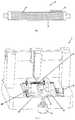
- FIG. 2it illustrates an overall structure of a 3D bio-printing platform for supplying nutrition according to an embodiment of the present invention.
- the bioprinting platformwhich is generally presented by reference sign 1 , mainly consists of a rotary rod 2 serving as a printing support rod and a nutrition supply system 3 for supplying nutrition. As illustrated in FIG. 1 , mainly consists of a rotary rod 2 serving as a printing support rod and a nutrition supply system 3 for supplying nutrition.
- the nutrition supply system 3comprises a nutrition solution container 6 ; a nutrition solution delivery tube 7 , with one end extending into the nutrition container 6 and the other end leading to an end of the rotary rod 2 ; a nutrition solution return tube 8 , with one end leading to the other end of the rotary rod 2 and the other end extending into the nutrition container 6 , and a pump 9 located in a line of the nutrition delivery tube 7 , such that during a 3D bio-printing process, the nutrition solution is sucked into the nutrition solution delivery tube 7 by the pump 9 and enters the hollow structure of the rotary rod 2 , so that a portion of the nutrition solution in the hollow structure exudes via at least one hole 4 in a surface of the rotary rod 2 , and the other portion of the nutrition solution is recycled into the nutrition solution container 6 through the hollow structure and via the nutrition solution return tube 8 .
- the nutrition solutionmay be an ordinary nutrition solution, and may also have special additive ingredients.
- the flow velocity of the nutrition solutionis controllable.
- the flow velocity of the nutrition solutionmay be regulated by a pump 9 located in the line of the nutrition solution delivery tube 7 , and other flow velocity control means may also be utilized as long as it can be ensured that the nutrition solution exudes from the surface of the rotary rod 2 .
- the line of the nutrition solution return tube 8is provided with a filtering means 10 to perform a filtering treatment of the nutrition solution returned into the nutrition container 6 .
- the rotary printing platformis a printing platform for supplying nutrition to different tissues and individual designs
- the nutrition supply manneris a manner of intra-platform permeation, or external spray or both of the two at the same time.
- the nutrition solutionis sprayed from outside towards the surface of the rotary rod 2 , so as to supply nutrition for cell printing.
- the temperature of the rotary printing platformis controllable, for example the regulation of the temperature may be effectuated by control of a temperature of the nutrition solution and by regulation of the ambient temperature.
- the method of printing a tubular tissue using the 3D bio-printing platformmay comprise: driving a rotary rod to rotate; and delivering a nutrition solution to the rotary rod by a nutrition supply system during a 3D bio-printing process, such that the nutrition solution passes through a hollow structure of the rotary rod and a portion of the nutrition solution exudes via at least one hole in a surface of the rotary rod.
- the methodmay further comprise a step of utilizing a computer to assist in designing a rotary rod by modeling according to body parameters or direct 3D modeling, before making a rotary rod.
- Modeling according to body parametersrefers to such a manner that data parameters are obtained by body scanning (such as MRI or CT) or other existing technical means, and then converted into three-dimensional model by assistance of a computer.
- Direct 3D modelingrefers to direct 3D modeling by parameters.
- the step of utilizing a computer to assist in designing a rotary rodcomprises utilizing a 3D modeling software and/or simulation technique to set parameters including mechanical strength, diameter, length, tube wall thickness, flexure and surface roughness of the rotary rod, shape, porosity, pore distribution, and aperture size of a hole in the surface of the rotary rod.
- the production of the rotary rodmay include the production of a rotary rod by a conventional method and a rotary rod printed by a 3D printer.
- the methodmay further comprise the steps of coating at least one layer of liquid-permeable biocompatible substance to a surface of the rotary rod; printing bioink (see FIG. 1 ), so that the nutrition solution exudes from the biocompatible substance via at least one hole in the surface of the rotary rod; and after a tubular tissue is printed and moulded, removing or separating a biocompatible substance on the surface of the rotary rod and then removing a tubular tissue from the rotary rod and culturing the same (for example placed in an incubator), or after a tubular tissue is printed, removing the rotary rod with the tubular tissue and culturing the same (for example placed in an incubator).
- the entire rotary rodmay offer mechanics-related stimulation to a printed tissue through a hole channel, or offer mechanical, biological and chemical stimuli externally.
- the present inventionwhich reduces the possibility of resulting in tissue collapse from the effect of gravity, provides a new method of 3D bio-printing a tubular tissue and supplying nutrition in a printing process, with a wide application prospect.
Landscapes
- Engineering & Computer Science (AREA)
- Health & Medical Sciences (AREA)
- Chemical & Material Sciences (AREA)
- Life Sciences & Earth Sciences (AREA)
- Materials Engineering (AREA)
- Organic Chemistry (AREA)
- Bioinformatics & Cheminformatics (AREA)
- Wood Science & Technology (AREA)
- Zoology (AREA)
- Biomedical Technology (AREA)
- Manufacturing & Machinery (AREA)
- General Health & Medical Sciences (AREA)
- Genetics & Genomics (AREA)
- Biotechnology (AREA)
- Microbiology (AREA)
- Biochemistry (AREA)
- General Engineering & Computer Science (AREA)
- Sustainable Development (AREA)
- Optics & Photonics (AREA)
- Physics & Mathematics (AREA)
- Mechanical Engineering (AREA)
- Oral & Maxillofacial Surgery (AREA)
- Veterinary Medicine (AREA)
- Public Health (AREA)
- Animal Behavior & Ethology (AREA)
- Transplantation (AREA)
- Cell Biology (AREA)
- Molecular Biology (AREA)
- Vascular Medicine (AREA)
- Cardiology (AREA)
- Heart & Thoracic Surgery (AREA)
- Pulmonology (AREA)
- Gastroenterology & Hepatology (AREA)
- Virology (AREA)
- Botany (AREA)
- Clinical Laboratory Science (AREA)
- Chemical Kinetics & Catalysis (AREA)
- Dermatology (AREA)
- Medicinal Chemistry (AREA)
- Epidemiology (AREA)
Abstract
Description
Claims (18)
Applications Claiming Priority (1)
| Application Number | Priority Date | Filing Date | Title |
|---|---|---|---|
| PCT/CN2015/075469WO2016154882A1 (en) | 2015-03-31 | 2015-03-31 | Rotary device for biological printing, and method of use thereof |
Publications (2)
| Publication Number | Publication Date |
|---|---|
| US20180112167A1 US20180112167A1 (en) | 2018-04-26 |
| US11149240B2true US11149240B2 (en) | 2021-10-19 |
Family
ID=57004730
Family Applications (1)
| Application Number | Title | Priority Date | Filing Date |
|---|---|---|---|
| US15/562,560Active2037-07-20US11149240B2 (en) | 2015-03-31 | 2015-03-31 | Rotary device for bio-printing and method for using the same |
Country Status (4)
| Country | Link |
|---|---|
| US (1) | US11149240B2 (en) |
| EP (2) | EP3689297A1 (en) |
| JP (1) | JP6568299B2 (en) |
| WO (1) | WO2016154882A1 (en) |
Cited By (1)
| Publication number | Priority date | Publication date | Assignee | Title |
|---|---|---|---|---|
| US20190010447A1 (en)* | 2015-12-30 | 2019-01-10 | Revitex Co., Ltd. | Printing module for biological printer, and biological printer |
Families Citing this family (12)
| Publication number | Priority date | Publication date | Assignee | Title |
|---|---|---|---|---|
| US10442175B2 (en)* | 2015-04-28 | 2019-10-15 | Warsaw Orthopedic, Inc. | 3D printing devices and methods |
| US11219976B2 (en)* | 2016-09-29 | 2022-01-11 | Gkn Aerospace Newington Llc | Manufacturing method for cylindrical parts |
| US10967570B2 (en)* | 2018-01-18 | 2021-04-06 | Revotek Co., Ltd | Device for printing lumen tissue construct, method for using the same and 3D bioprinter |
| US11311368B2 (en)* | 2018-01-18 | 2022-04-26 | Revotek Co., Ltd | Device for printing lumen tissue construct, method for using the same and 3D bioprinter |
| KR102065474B1 (en)* | 2018-10-10 | 2020-01-14 | 재단법인 의약바이오컨버젼스연구단 | 3d bioprinter and operating methods thereof |
| US11312071B2 (en)* | 2018-11-12 | 2022-04-26 | Ossur Iceland Ehf | Additive manufacturing system, method and corresponding components for making elastomeric structures |
| WO2020214328A2 (en)* | 2019-03-19 | 2020-10-22 | University Of Pittsburgh - Of The Commonwealth System Of Higher Education | Automation mechanism for pre/clinical production of resorbable nerve guides |
| KR102253724B1 (en)* | 2019-11-26 | 2021-05-20 | 주식회사 티앤알바이오팹 | Rotational 3d printing base and 3d printer including thereof |
| TWI744152B (en)* | 2020-12-28 | 2021-10-21 | 高鼎精密材料股份有限公司 | 3d printing device |
| CN112843334B (en)* | 2021-01-13 | 2022-07-08 | 东华大学 | A kind of three-dimensional printing composite aerogel to construct a simulated gas pipe and its preparation method |
| CN113085175B (en)* | 2021-02-24 | 2023-06-02 | 华清智美(深圳)生物科技有限公司 | Tubular 3D biological printing typical process platform device |
| CN113679506A (en)* | 2021-07-07 | 2021-11-23 | 兰州大学 | A simple preparation method of 3D printing inner wall micropatterned nerve conduit |
Citations (11)
| Publication number | Priority date | Publication date | Assignee | Title |
|---|---|---|---|---|
| WO1998025546A1 (en) | 1996-12-10 | 1998-06-18 | Cook Biotech, Inc. | Tubular grafts from purified submucosa |
| US20020049489A1 (en) | 2000-07-11 | 2002-04-25 | Herweck Steve A. | Prosthesis and method of making a prosthesis having an external support structure |
| WO2003079985A2 (en) | 2002-03-18 | 2003-10-02 | Carnegie Mellon University | Method and apparatus for preparing biomimetic scaffold |
| JP2006141290A (en) | 2004-11-19 | 2006-06-08 | Nippon Sheet Glass Co Ltd | Carrier for biochemical application |
| WO2007136227A1 (en) | 2006-05-23 | 2007-11-29 | Hyunjin Yang | Non-spherical three-dimensional micro-scaffold for cell culture and delivery prepared using rapid prototyping system |
| CN101294131A (en) | 2007-04-27 | 2008-10-29 | 中国药品生物制品检定所 | Bioreactor for vascellum tissue engineering |
| US20100330144A1 (en) | 2009-06-25 | 2010-12-30 | 3D Biotek, Llc | Methods and Apparatus for Fabricating Porous Three-Dimensional Tubular Scaffolds |
| CN103462725A (en) | 2013-08-06 | 2013-12-25 | 浙江大学 | Printing device for three-dimensional biological structure and printing method |
| US20140014751A1 (en)* | 2012-07-13 | 2014-01-16 | Casabella Holdings, Llc | Rotary grater with storage device |
| CN104146793A (en) | 2014-07-28 | 2014-11-19 | 浙江大学 | Biological-activity organ manufacturing method |
| CN104146794A (en) | 2014-08-24 | 2014-11-19 | 周惠兴 | Blood vessel forming device and method for 3D bioprinting |
Family Cites Families (1)
| Publication number | Priority date | Publication date | Assignee | Title |
|---|---|---|---|---|
| SG11201600770RA (en)* | 2013-07-31 | 2016-02-26 | Organovo Inc | Automated devices, systems, and methods for the fabrication of tissue |
- 2015
- 2015-03-31JPJP2018502296Apatent/JP6568299B2/ennot_activeExpired - Fee Related
- 2015-03-31WOPCT/CN2015/075469patent/WO2016154882A1/ennot_activeCeased
- 2015-03-31USUS15/562,560patent/US11149240B2/enactiveActive
- 2015-03-31EPEP20164169.3Apatent/EP3689297A1/ennot_activeWithdrawn
- 2015-03-31EPEP15886868.7Apatent/EP3278765B1/ennot_activeNot-in-force
Patent Citations (12)
| Publication number | Priority date | Publication date | Assignee | Title |
|---|---|---|---|---|
| WO1998025546A1 (en) | 1996-12-10 | 1998-06-18 | Cook Biotech, Inc. | Tubular grafts from purified submucosa |
| JP2008029866A (en) | 1996-12-10 | 2008-02-14 | Cook Biotech Inc | Tubular grafts from purified submucosa |
| US20020049489A1 (en) | 2000-07-11 | 2002-04-25 | Herweck Steve A. | Prosthesis and method of making a prosthesis having an external support structure |
| WO2003079985A2 (en) | 2002-03-18 | 2003-10-02 | Carnegie Mellon University | Method and apparatus for preparing biomimetic scaffold |
| JP2006141290A (en) | 2004-11-19 | 2006-06-08 | Nippon Sheet Glass Co Ltd | Carrier for biochemical application |
| WO2007136227A1 (en) | 2006-05-23 | 2007-11-29 | Hyunjin Yang | Non-spherical three-dimensional micro-scaffold for cell culture and delivery prepared using rapid prototyping system |
| CN101294131A (en) | 2007-04-27 | 2008-10-29 | 中国药品生物制品检定所 | Bioreactor for vascellum tissue engineering |
| US20100330144A1 (en) | 2009-06-25 | 2010-12-30 | 3D Biotek, Llc | Methods and Apparatus for Fabricating Porous Three-Dimensional Tubular Scaffolds |
| US20140014751A1 (en)* | 2012-07-13 | 2014-01-16 | Casabella Holdings, Llc | Rotary grater with storage device |
| CN103462725A (en) | 2013-08-06 | 2013-12-25 | 浙江大学 | Printing device for three-dimensional biological structure and printing method |
| CN104146793A (en) | 2014-07-28 | 2014-11-19 | 浙江大学 | Biological-activity organ manufacturing method |
| CN104146794A (en) | 2014-08-24 | 2014-11-19 | 周惠兴 | Blood vessel forming device and method for 3D bioprinting |
Non-Patent Citations (3)
| Title |
|---|
| Extended Supplementary European Search Report dated Oct. 31, 2018 in European Patent Application No. 15 88 6868.7. |
| International Search Report dated Jan. 5, 2016 issued in PCT/CN2015/075469. |
| Japanese Notice of Reasons for Rejection dated Dec. 4, 2018 received in Japanese Patent Application No. 2018-502296, together with an English-language translation. |
Cited By (1)
| Publication number | Priority date | Publication date | Assignee | Title |
|---|---|---|---|---|
| US20190010447A1 (en)* | 2015-12-30 | 2019-01-10 | Revitex Co., Ltd. | Printing module for biological printer, and biological printer |
Also Published As
| Publication number | Publication date |
|---|---|
| WO2016154882A1 (en) | 2016-10-06 |
| JP2018511345A (en) | 2018-04-26 |
| JP6568299B2 (en) | 2019-08-28 |
| US20180112167A1 (en) | 2018-04-26 |
| EP3689297A1 (en) | 2020-08-05 |
| EP3278765A1 (en) | 2018-02-07 |
| EP3278765A4 (en) | 2018-12-05 |
| EP3278765B1 (en) | 2020-06-17 |
Similar Documents
| Publication | Publication Date | Title |
|---|---|---|
| US11149240B2 (en) | Rotary device for bio-printing and method for using the same | |
| Kačarević et al. | An introduction to 3D bioprinting: possibilities, challenges and future aspects | |
| Wang et al. | In situ 3D bioprinting living photosynthetic scaffolds for autotrophic wound healing | |
| Holland et al. | 3D biofabrication for tubular tissue engineering | |
| Dell et al. | 3D bioprinting using hydrogels: cell inks and tissue engineering applications | |
| Ozbolat et al. | Bioprinting toward organ fabrication: challenges and future trends | |
| CN110302428B (en) | Cartilage-bone-marrow composite tissue structure and method based on living cell 3D printing | |
| CN104207859B (en) | Rotation method of piling is utilized to prepare method and the special equipment of histoorgan | |
| CN107320780A (en) | A kind of multilayer aquagel of hollow tubular structure and preparation method and application | |
| KR20170003918A (en) | Methods, devices, and systems for the fabrication of materials and tissues utilizing electromagnetic radiation | |
| CN110403731B (en) | Tissue engineering bionic liver lobe structure based on living cell 3D printing and preparation method | |
| Willson et al. | Bioprinting au natural: the biologics of bioinks | |
| US20110091926A1 (en) | Perfusable bioreactor for the production of human or animal tissues | |
| CN110408539B (en) | Construction method of bionic vascular network in large-volume tissue engineering tissue organ | |
| CN109749983A (en) | A method for improving the activity of appendages in artificial skin and controlling their distribution | |
| Salg et al. | Vascularization in bioartificial parenchymal tissue: bioink and bioprinting strategies | |
| CN106137456B (en) | A kind of rotating device and its application method for biometric print | |
| CN204971703U (en) | 3D is biological to be printed with rotary rod and can supply with biological print platform of nutritive 3D | |
| CN110545758B (en) | Tissue engineering scaffold | |
| Veeravalli et al. | Three-dimensional bioprinting in medicine: a comprehensive overview of current progress and challenges faced | |
| Chowdhury et al. | 3D printed bioscaffolds for developing tissue-engineered constructs | |
| Melchiorri et al. | Bioprinting of blood vessels | |
| CN113677505B (en) | Three-dimensional bioprinting system and method | |
| US20230256196A1 (en) | A Hybrid Bioscaffold-Intravascular Catheter for Cellular Therapies | |
| Conese | Bioprinting: A further step to effective regenerative medicine and Tissue Engineering |
Legal Events
| Date | Code | Title | Description |
|---|---|---|---|
| FEPP | Fee payment procedure | Free format text:ENTITY STATUS SET TO UNDISCOUNTED (ORIGINAL EVENT CODE: BIG.); ENTITY STATUS OF PATENT OWNER: SMALL ENTITY | |
| FEPP | Fee payment procedure | Free format text:ENTITY STATUS SET TO SMALL (ORIGINAL EVENT CODE: SMAL); ENTITY STATUS OF PATENT OWNER: SMALL ENTITY | |
| STPP | Information on status: patent application and granting procedure in general | Free format text:DOCKETED NEW CASE - READY FOR EXAMINATION | |
| AS | Assignment | Owner name:REVOTEK CO., LTD, CHINA Free format text:ASSIGNMENT OF ASSIGNORS INTEREST;ASSIGNORS:KANG, YUJIAN JAMES;ZHOU, HUIXING;REEL/FRAME:047130/0641 Effective date:20180925 | |
| STPP | Information on status: patent application and granting procedure in general | Free format text:NON FINAL ACTION MAILED | |
| STPP | Information on status: patent application and granting procedure in general | Free format text:RESPONSE TO NON-FINAL OFFICE ACTION ENTERED AND FORWARDED TO EXAMINER | |
| STPP | Information on status: patent application and granting procedure in general | Free format text:RESPONSE TO NON-FINAL OFFICE ACTION ENTERED AND FORWARDED TO EXAMINER | |
| STPP | Information on status: patent application and granting procedure in general | Free format text:NON FINAL ACTION MAILED | |
| STPP | Information on status: patent application and granting procedure in general | Free format text:RESPONSE TO NON-FINAL OFFICE ACTION ENTERED AND FORWARDED TO EXAMINER | |
| STPP | Information on status: patent application and granting procedure in general | Free format text:FINAL REJECTION MAILED | |
| STPP | Information on status: patent application and granting procedure in general | Free format text:RESPONSE AFTER FINAL ACTION FORWARDED TO EXAMINER | |
| STPP | Information on status: patent application and granting procedure in general | Free format text:NOTICE OF ALLOWANCE MAILED -- APPLICATION RECEIVED IN OFFICE OF PUBLICATIONS | |
| STPP | Information on status: patent application and granting procedure in general | Free format text:PUBLICATIONS -- ISSUE FEE PAYMENT RECEIVED | |
| STPP | Information on status: patent application and granting procedure in general | Free format text:PUBLICATIONS -- ISSUE FEE PAYMENT VERIFIED | |
| STCF | Information on status: patent grant | Free format text:PATENTED CASE | |
| FEPP | Fee payment procedure | Free format text:MAINTENANCE FEE REMINDER MAILED (ORIGINAL EVENT CODE: REM.); ENTITY STATUS OF PATENT OWNER: SMALL ENTITY |