US11147562B2 - Systems and methods for embolic implant detachment - Google Patents
Systems and methods for embolic implant detachmentDownload PDFInfo
- Publication number
- US11147562B2 US11147562B2US16/218,342US201816218342AUS11147562B2US 11147562 B2US11147562 B2US 11147562B2US 201816218342 AUS201816218342 AUS 201816218342AUS 11147562 B2US11147562 B2US 11147562B2
- Authority
- US
- United States
- Prior art keywords
- delivery tube
- introducer sheath
- length
- proximal end
- interference feature
- Prior art date
- Legal status (The legal status is an assumption and is not a legal conclusion. Google has not performed a legal analysis and makes no representation as to the accuracy of the status listed.)
- Active, expires
Links
Images


Classifications
- A—HUMAN NECESSITIES
- A61—MEDICAL OR VETERINARY SCIENCE; HYGIENE
- A61B—DIAGNOSIS; SURGERY; IDENTIFICATION
- A61B17/00—Surgical instruments, devices or methods
- A61B17/12—Surgical instruments, devices or methods for ligaturing or otherwise compressing tubular parts of the body, e.g. blood vessels or umbilical cord
- A61B17/12022—Occluding by internal devices, e.g. balloons or releasable wires
- A61B17/12099—Occluding by internal devices, e.g. balloons or releasable wires characterised by the location of the occluder
- A61B17/12109—Occluding by internal devices, e.g. balloons or releasable wires characterised by the location of the occluder in a blood vessel
- A61B17/12113—Occluding by internal devices, e.g. balloons or releasable wires characterised by the location of the occluder in a blood vessel within an aneurysm
- A—HUMAN NECESSITIES
- A61—MEDICAL OR VETERINARY SCIENCE; HYGIENE
- A61B—DIAGNOSIS; SURGERY; IDENTIFICATION
- A61B17/00—Surgical instruments, devices or methods
- A61B17/12—Surgical instruments, devices or methods for ligaturing or otherwise compressing tubular parts of the body, e.g. blood vessels or umbilical cord
- A61B17/12022—Occluding by internal devices, e.g. balloons or releasable wires
- A61B17/12131—Occluding by internal devices, e.g. balloons or releasable wires characterised by the type of occluding device
- A61B17/1214—Coils or wires
- A—HUMAN NECESSITIES
- A61—MEDICAL OR VETERINARY SCIENCE; HYGIENE
- A61F—FILTERS IMPLANTABLE INTO BLOOD VESSELS; PROSTHESES; DEVICES PROVIDING PATENCY TO, OR PREVENTING COLLAPSING OF, TUBULAR STRUCTURES OF THE BODY, e.g. STENTS; ORTHOPAEDIC, NURSING OR CONTRACEPTIVE DEVICES; FOMENTATION; TREATMENT OR PROTECTION OF EYES OR EARS; BANDAGES, DRESSINGS OR ABSORBENT PADS; FIRST-AID KITS
- A61F2/00—Filters implantable into blood vessels; Prostheses, i.e. artificial substitutes or replacements for parts of the body; Appliances for connecting them with the body; Devices providing patency to, or preventing collapsing of, tubular structures of the body, e.g. stents
- A61F2/01—Filters implantable into blood vessels
- A—HUMAN NECESSITIES
- A61—MEDICAL OR VETERINARY SCIENCE; HYGIENE
- A61F—FILTERS IMPLANTABLE INTO BLOOD VESSELS; PROSTHESES; DEVICES PROVIDING PATENCY TO, OR PREVENTING COLLAPSING OF, TUBULAR STRUCTURES OF THE BODY, e.g. STENTS; ORTHOPAEDIC, NURSING OR CONTRACEPTIVE DEVICES; FOMENTATION; TREATMENT OR PROTECTION OF EYES OR EARS; BANDAGES, DRESSINGS OR ABSORBENT PADS; FIRST-AID KITS
- A61F2/00—Filters implantable into blood vessels; Prostheses, i.e. artificial substitutes or replacements for parts of the body; Appliances for connecting them with the body; Devices providing patency to, or preventing collapsing of, tubular structures of the body, e.g. stents
- A61F2/95—Instruments specially adapted for placement or removal of stents or stent-grafts
- A—HUMAN NECESSITIES
- A61—MEDICAL OR VETERINARY SCIENCE; HYGIENE
- A61B—DIAGNOSIS; SURGERY; IDENTIFICATION
- A61B17/00—Surgical instruments, devices or methods
- A61B2017/00743—Type of operation; Specification of treatment sites
- A61B2017/00778—Operations on blood vessels
- A—HUMAN NECESSITIES
- A61—MEDICAL OR VETERINARY SCIENCE; HYGIENE
- A61B—DIAGNOSIS; SURGERY; IDENTIFICATION
- A61B17/00—Surgical instruments, devices or methods
- A61B17/12—Surgical instruments, devices or methods for ligaturing or otherwise compressing tubular parts of the body, e.g. blood vessels or umbilical cord
- A61B17/12022—Occluding by internal devices, e.g. balloons or releasable wires
- A61B2017/1205—Introduction devices
- A61B2017/12054—Details concerning the detachment of the occluding device from the introduction device
- A—HUMAN NECESSITIES
- A61—MEDICAL OR VETERINARY SCIENCE; HYGIENE
- A61F—FILTERS IMPLANTABLE INTO BLOOD VESSELS; PROSTHESES; DEVICES PROVIDING PATENCY TO, OR PREVENTING COLLAPSING OF, TUBULAR STRUCTURES OF THE BODY, e.g. STENTS; ORTHOPAEDIC, NURSING OR CONTRACEPTIVE DEVICES; FOMENTATION; TREATMENT OR PROTECTION OF EYES OR EARS; BANDAGES, DRESSINGS OR ABSORBENT PADS; FIRST-AID KITS
- A61F2/00—Filters implantable into blood vessels; Prostheses, i.e. artificial substitutes or replacements for parts of the body; Appliances for connecting them with the body; Devices providing patency to, or preventing collapsing of, tubular structures of the body, e.g. stents
- A61F2/01—Filters implantable into blood vessels
- A61F2/011—Instruments for their placement or removal
- A—HUMAN NECESSITIES
- A61—MEDICAL OR VETERINARY SCIENCE; HYGIENE
- A61M—DEVICES FOR INTRODUCING MEDIA INTO, OR ONTO, THE BODY; DEVICES FOR TRANSDUCING BODY MEDIA OR FOR TAKING MEDIA FROM THE BODY; DEVICES FOR PRODUCING OR ENDING SLEEP OR STUPOR
- A61M25/00—Catheters; Hollow probes
- A61M25/0021—Catheters; Hollow probes characterised by the form of the tubing
- A61M2025/0042—Microcatheters, cannula or the like having outside diameters around 1 mm or less
- A—HUMAN NECESSITIES
- A61—MEDICAL OR VETERINARY SCIENCE; HYGIENE
- A61M—DEVICES FOR INTRODUCING MEDIA INTO, OR ONTO, THE BODY; DEVICES FOR TRANSDUCING BODY MEDIA OR FOR TAKING MEDIA FROM THE BODY; DEVICES FOR PRODUCING OR ENDING SLEEP OR STUPOR
- A61M25/00—Catheters; Hollow probes
- A61M25/0067—Catheters; Hollow probes characterised by the distal end, e.g. tips
- A61M25/0074—Dynamic characteristics of the catheter tip, e.g. openable, closable, expandable or deformable
- A61M2025/0079—Separate user-activated means, e.g. guidewires, guide tubes, balloon catheters or sheaths, for sealing off an orifice, e.g. a lumen or side holes, of a catheter
Definitions
- the present inventiongenerally relates to aneurysm treatment devices and more particularly, to delivery systems for embolic implants.
- Implant devicesare known in the field. Many are deployed mechanically, via systems that combine one or more catheters and wires for delivery. Examples of implants that can be delivered mechanically include embolic elements, stents, grafts, drug delivery implants, flow diverters, filters, stimulation leads, sensing leads, or other implantable structures delivered through a microcatheter. Some obstetric and gastrointestinal implants may also be implanted via similar systems that combine one or more catheters and wires. Devices that may be released or deployed by mechanical means vary greatly in design but can employ a similar delivery catheter and wire system. Many such catheter-based delivery systems include a wire for retention of the implant in the catheter until the time for release of the device. These systems are then actuated by retracting or pulling the wire relative to the catheter. Such a wire is referred to herein as a “pull wire”.
- a physiciancan use one of many known deployment apparatuses.
- Such mechanical deployment apparatusesare typically separate from the delivery system and have moving parts for gripping the pull wire and for moving the pull wire proximally.
- Deployment methods and apparatuses that do not require auxiliary components and/or complex moving partscan simplify treatment procedures and reduce cost. There is therefore a need for simplified mechanical implant deployment apparatuses.
- Examplescan generally include an embolic implantation system that includes an embolic implant, a delivery system, and an introducer sheath that are collectively designed so that the combination of the introducer sheath and the delivery system can be used as a deployment apparatus for the embolic implant.
- the delivery systemcan have a pull wire, a delivery tube, and an interference feature attached to the pull wire and positioned at a proximal end of the delivery tube.
- the introducer sheathcan be moved proximally over the delivery tube until it engages the interference feature.
- the introducer sheathcan be pressed against the interference feature, causing the interference feature to move proximally in relation to the delivery tube, thereby proximally pulling the pull wire to which the interference feature is attached and deploying the implant.
- An example implantation systemcan include a delivery tube, an embolic coil, an introducer sheath, an interference feature, and an elongated member.
- the embolic coilcan be detachably attached to a distal end of the delivery tube.
- the interference featurecan be positioned at a proximal end of the delivery tube and movable in relation to the delivery tube.
- the elongated membercan be positioned within a lumen of the delivery tube and attached to the interference feature.
- the introducer sheathcan have a lumen sized to slidably receive the delivery tube and the embolic coil, the introducer sheath can be translatable over the delivery tube from the distal end of the delivery tube to the proximal end of the delivery tube, and the introducer sheath can be sized to engage the interference feature.
- the interference featurecan be movable in relation to the delivery tube in response to a force applied by the introducer sheath against the interference feature.
- the elongated membercan be movable in relation to the delivery tube in response to a proximal movement of the interference feature.
- the interference featurecan be detachable from the delivery tube.
- the elongated membercan be movable to exit the proximal end of the delivery tube in response to a proximal movement of the detached interference feature.
- the delivery tubecan have a soft section near the distal end of the delivery tube.
- the length of the embolic coil and the soft section as measured from a distal end of the un-implanted embolic coil to a proximal end of the soft sectioncan be shorter than the end-to-end length of the introducer sheath so that the introducer sheath is sized to fully encompass the un-implanted embolic coil and the soft section.
- the introducer sheathcan be longer than the length of the embolic coil and soft section by about 5 cm.
- the systemcan include a microcatheter, and the delivery tube can have an end-to-end length that is longer than the sum of the end-to-end length of the introducer sheath and an end-to-end length of the microcatheter.
- the end-to-end length of the introducer sheathcan be between about 46 cm to about 105 cm.
- the introducer sheathcan be movable from a packaged configuration in which the introducer sheath is positioned to completely encompass the soft section and the embolic coil to a deployment configuration in which the introducer sheath is engaged with the interference feature.
- the embolic coilcan be detached from the delivery tube by moving the elongated member proximally in relation to the delivery tube.
- the interference featurecan have a substantially circular surface positioned to engage the proximal end of the introducer sheath.
- a distal end of the introducer sheathcan be sized to engage a microcatheter to create an enclosed interface through which the embolic coil and at least a portion of the delivery tube can pass.
- An example implantation assemblycan include a delivery tube, an embolic implant, a pull wire, an engagement bump, and a tubular sheath.
- the embolic implantcan be attached to a distal end of the delivery tube.
- the pull wirecan be disposed within a lumen of the delivery tube and movable to detach the embolic implant from the delivery tube.
- the engagement bumpcan be disposed on a proximal end of the pull wire and positioned near a proximal end of the delivery tube.
- the tubular sheathcan be conveyable over the embolic implant and the delivery tube from a distal end of the embolic implant to the proximal end of the delivery tube, and the tubular sheath can be sized to engage the engagement bump.
- the engagement bump and the pull wirecan be movable in relation to the delivery tube in response to a force applied by the tubular sheath to the engagement bump.
- the delivery tubecan have a soft section extending proximally from the distal end of the delivery tube, and the tubular sheath can measure end-to-end about 5 cm longer than a length measured from a distal end of the embolic implant to a proximal end of the soft section when the embolic implant is attached to the delivery tube and extended in an un-implanted configuration.
- the assemblycan include a microcatheter, and the delivery tube can have an end-to-end length that is greater than the sum of the length of the introducer sheath and the microcatheter.
- the tubular sheathcan be movable from a packaged configuration in which the tubular sheath is positioned to completely encompass the soft section and the embolic coil to a deployment configuration in which the tubular sheath is engaged with the engagement bump.
- the engagement bumpcan be detachable from the delivery tube in response to the force applied by the tubular sheath to the engagement bump.
- the pull wirecan be movable to detach the embolic implant from the delivery tube in response to the force applied by the tubular sheath to the engagement bump.
- An example method for treating an aneurysmcan include the steps of providing an implantation system including an embolic implant, an introducer sheath, a delivery tube, an interference feature, and a pull wire; affixing the pull wire to the interference feature; positioning the pull wire within a lumen of the delivery tube; attaching the interference feature to a proximal end of the delivery tube; attaching the embolic implant at a distal end of the delivery tube; positioning the introducer sheath to encompass the embolic implant and a first portion of the delivery tube; sliding the introducer sheath proximally over the delivery tube; pulling the introducer sheath proximally to apply a force from the introducer sheath to the interference feature; and moving the interference feature and the pull wire proximally in relation to the delivery tube in response to the force.
- the first portion of the delivery tube over which the introducer sheath is positioned in the example methodcan have a soft section.
- the methodcan include sizing the introducer sheath to have a length that is greater than the length of the embolic implant and the soft section by about 5 cm.
- the methodcan include sizing the introducer sheath to have a length of between about 46 cm to about 105 cm, the length measurable from a distal end to a proximal end of the introducer sheath.
- the methodcan include detaching the embolic implant from the delivery tube in response to moving the interference feature and the pull wire proximally in relation to the delivery tube.
- the methodcan include detaching the interference feature from the delivery tube.
- the interference featurecan be detached in response to moving the interference feature and the pull wire proximally in relation to the delivery tube.
- the methodcan include providing a microcatheter; positioning the introducer sheath to engage with the microcatheter while maintaining the embolic implant and the first portion of the delivery tube within the inducer sheath; and translating the embolic implant and the delivery tube distally to position the embolic implant and the first portion of the delivery tube within the microcatheter.
- FIG. 1is an illustration of an exemplary implantation system according to aspects of the present invention
- FIGS. 2A and 2Bare illustrations of an exemplary implantation system such as illustrated in FIG. 1 interfacing with a microcatheter according to aspects of the present invention
- FIGS. 3A through 3Care illustrations of implantation steps that can be performed with an exemplary implantation system such as illustrated in FIG. 1 according to aspects of the present invention
- FIG. 4Aillustrates an exemplary implantation system having a breakable disconnection feature according to aspects of the present invention
- FIG. 4Billustrates a cross-sectional view near a proximal end of the exemplary implantation system of FIG. 4A as indicated in FIG. 4A and according to aspects of the present invention
- FIG. 5Aillustrates an exemplary implantation system having a twist-lock disconnection feature according to aspects of the present invention
- FIG. 5Billustrates a cross-sectional view near a proximal end of the exemplary implantation system of FIG. 5A as indicated in FIG. 5A and according to aspects of the present invention
- FIG. 6Aillustrates an exemplary implantation system having a sliding track according to aspects of the present invention
- FIG. 6Billustrates a cross-sectional view near a proximal end of the exemplary implantation system of FIG. 6A as indicated in FIG. 6A and according to aspects of the present invention
- FIG. 7Aillustrates an exemplary implantation system having a stretchable segment according to aspects of the present invention
- FIG. 7Billustrates a cross-sectional view near a proximal end of the exemplary implantation system of FIG. 7A as indicated in FIG. 7A and according to aspects of the present invention
- FIGS. 8A through 8Cillustrate cut-away views of an exemplary implantation system having a stretchable segment and a disconnecting feature according to aspects of the present invention.
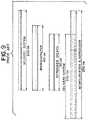
- FIG. 9illustrates relative dimensions of a delivery system, microcatheter, and introducer sheath as known in the art.
- Examples presented hereinutilize an introducer sheath to facilitate mechanical deployment of an implant.
- implants that can be delivered mechanicallyinclude embolic elements, stents, grafts, drug delivery implants, flow diverters, filters, stimulation leads, sensing leads, or other implantable structures deliverable through a microcatheter.
- Some implantsare currently packaged with an introducer sheath that is removed from the device and discarded near the beginning of an implantation procedure.
- embolic coils and other embolic implantscan be used to occlude vessels in a variety of medical applications.
- the embolic implantis contained in an introducer sheath.
- the introducer sheathIn present treatment practices, once the embolic implant is transferred to a microcatheter, the introducer sheath would be removed from the delivery system and discarded before the embolic implant reaches a treatment site.
- the introducer sheathcan be slid proximally and can facilitate deployment of the embolic implant, i.e. detachment of the embolic implant from the delivery system.
- the delivery systemcan have an interference feature positioned at a proximal end of a delivery tube and attached to a pull wire, and the combination of the introducer sheath, delivery tube, pull wire, and interference feature can be configured such that the introducer sheath can engage with the interference feature and move the interference feature proximally in relation to the delivery tube, thereby pulling the pull wire proximally and deploying the embolic implant.
- the delivery tube, microcatheter, and introducer sheathcan each have a respective length sized such that the introducer sheath can be long enough to cover the embolic implant and sensitive portions of the delivery system, and the delivery tube can be long enough to extend through the entire length of the microcatheter and the entire length of the introducer sheath.
- FIG. 1is an illustration of an exemplary implantation system 100 .
- the implantation system 100can have an embolic implant 140 such as an embolic coil, embolic braid, or other such implant for filling an aneurysm sac, a delivery tube 110 for delivering the embolic implant 140 to a treatment site, a pull wire 130 disposed within the delivery tube that can be pulled proximally to deploy the embolic implant 140 , an interference feature 120 positioned at a proximal end 112 of the delivery tube 110 attached to the pull wire 130 that can be pulled proximally to pull the pull wire 130 proximally, and an introducer sheath 180 that can be moved proximally to engage the interference feature 120 and pull the interference feature 120 proximally.
- an embolic implant 140such as an embolic coil, embolic braid, or other such implant for filling an aneurysm sac
- a delivery tube 110for delivering the embolic implant 140 to a treatment site
- a pull wire 130disposed within the
- the introducer sheath 180can have a lumen therethrough that is sized to slidably receive the delivery tube 110 and the embolic implant 140 .
- the introducer sheath 180can be sized such that it can be translated proximally from the position illustrated in FIG. 1 over a length of the delivery tube 110 to engage the interference feature 120 positioned at the proximal end 112 of the delivery tube 110 .
- the interference feature 120can be movable in relation to the delivery tube 110 .
- the interference feature 120can be detachably attached to the proximal end 112 of the delivery tube 110 , and the system 100 can include a disconnection feature 122 that can be unhooked, torn, broken, twisted, or otherwise manipulated to disconnect the interference feature 120 from the delivery tube 110 .
- the delivery tube 110can have a soft section 116 positioned near a distal end 114 of the delivery tube 110 that has a greater flexibility than the remainder (proximal portion) 118 of the delivery tube 110 .
- the embolic implant 140can be detachably attached to a distal end 114 of the delivery tube 114 .
- the soft section 116can be designed to allow greater control and stability of the distal end 114 of the delivery tube 110 during implantation and deployment of the embolic implant 140 .
- the soft section 116can have laser cut notches or groves, and/or the soft section 116 can be made of a more flexible material compared to the remainder 118 of the delivery tube 110 .
- the introducer sheath 180can serve the purpose of protecting (packaging) the embolic implant 140 and the soft section 116 of the delivery tube 110 as the system 100 is being handled prior to, and at the beginning of a patient treatment procedure. For this purpose, it is therefore desirable for the introducer sheath 180 to be long enough to completely encompass the embolic implant 140 and the soft section 116 prior to the treatment procedure.
- the combined length of the embolic implant 140 and the soft section 116can be measured from a distal end 144 of the embolic implant 140 to a proximal end 117 of the soft section 116 .
- the introducer sheath 180can have a length measurable from a distal end 184 to a proximal end 182 of the introducer sheath that can be sized a few centimeters longer than the combined length of the embolic implant 140 and the soft section 116 to ensure that the embolic implant 140 and soft section 116 remain protected in case portions of the system 100 shift during handling prior to the treatment procedure.
- the introducer sheath 180can have a length that is about 5 cm longer than the combined length of the embolic implant 140 and the soft section 116 .
- the embolic implant 140can have a length of between about 1 cm and about 60 cm, the soft section 116 can have a length of about 40 cm, and the introducer sheath can have a length that is about 5 cm longer than the sum of the embolic implant 140 length and the soft section 116 length, i.e. between about 46 cm and about 105 cm.
- FIGS. 2A and 2Bare illustrations of an exemplary implantation system such as illustrated in FIG. 1 interfacing with a microcatheter 200 .
- FIG. 2Aillustrates an instant of a treatment procedure near the beginning of the treatment procedure in which an introducer sheath 180 is positioned to cover an embolic implant 140 and a soft portion 116 of a delivery tube 110 in a packaged configuration and a distal end 184 of the introducer sheath 180 is mated or engaged with a proximal end of the microcatheter 200 . As shown in FIG.
- the distal end 184 of the introducer sheath 180can be sized to engage the microcatheter 200 to create an enclosed interface through which the embolic implant 140 and the soft portion 116 of the delivery tube 110 can pass.
- the embolic implant 140 and the delivery tube 110can be translated distally to push the embolic implant 140 and a portion of the delivery tube 110 into the microcatheter 200 .
- FIG. 2Billustrates an instant of the treatment procedure in which the embolic implant 140 and the soft portion 116 are positioned within the microcatheter 200 .
- the embolic implant 140 and the soft portion 116are protected by the microcatheter 200 and the introducer sheath can now be pulled proximally 180 or left in place as the delivery tube 110 and embolic implant 140 are further translated distally.
- FIGS. 3A through 3Care illustrations of an exemplary implantation system during a series of example implantation steps.
- FIG. 3Aillustrates an embolic implant 140 and a soft portion 116 of a delivery tube 110 positioned inside a microcatheter 200 and an introducer sheath 180 being translated proximally over a proximal portion 118 of the delivery tube 110 .
- the introducer sheath 180can be disengaged from the microcatheter 200 and pulled proximally once the embolic implant 140 and soft section 116 are protected within the microcatheter 200 , but before the embolic implant 140 is positioned at a treatment site or within an aneurysm.
- the introducer sheath 180can remain engaged to the microcatheter until the embolic implant 140 is positioned at the treatment site or ready to be deployed from the delivery tube 110 and then pulled proximally after the embolic implant 140 is positioned at the treatment site.
- FIG. 3Billustrates the introducer sheath 180 in a deployment configuration in which the introducer sheath 180 is engaged with an interference feature 120 positioned near a proximal end 112 of the delivery tube 110 .
- the introducer sheath 180is shown providing a force F against the interference feature 120 .
- the forcecan be sufficient to move the interference feature 120 proximally in relation to the delivery tube 110 .
- the interference feature 120Prior to the application of the force F, the interference feature 120 can be detachably attached to the proximal end 112 of the delivery tube 110 , and the interference feature 120 can be detached from the proximal end 112 of the delivery tube 110 in response to the force F.
- the interference feature 120can remain attached to the delivery tube 110 and the force F can be sufficient to move the interference feature 120 in relation to the delivery tube 110 .
- the introducer sheath 180can be sized to engage the interference feature 120 .
- the introducer sheath 180can be tubular and can have a circular proximal end 182 , and the interference feature 120 can protrude radially beyond a circumference of the delivery tube 110 .
- the interference feature 120can be circular, having a circumference larger than a circumference of the proximal end 182 of the introducer sheath 180 .
- the interference feature 120can provide a flat surface against which the proximal end 182 of the introducer sheath 180 can press. Additionally, or alternatively, the interference feature can have a non-flat surface that can have a slope or a groove for receiving the introducer sheath 180 .
- the interference feature 120can be a bump positioned near the distal end of the delivery tube that extends beyond the circumference of the delivery tube and extends so that the introducer sheath 180 , when slid proximally over the delivery tube 110 , must engage the interference feature 120 before sliding completely over and off the proximal end 112 of the delivery tube 110 .
- FIG. 3Cillustrates the interference feature 120 after being moved proximally in relation to the delivery tube 110 in response to the force F from the introducer sheath 180 .
- the interference feature 120can be attached to a pull wire 130 , and the pull wire 130 can be pulled proximally when the interference feature 180 is moved proximally.
- the interference feature 120can be detachably attached to the delivery tube 110 prior to the proximal movement of the interference feature 120 , and a detachment feature 122 can be manipulated to facilitate the detachment of the interference feature 120 .
- the interference feature 120can be pulled proximally away from the delivery tube 110 , and the pull wire 130 can be moved to exit the proximal end 112 of the delivery tube 110 in response to the pulling of the interference feature 120 .
- the pull wire 130can be an elongated member that extends through a lumen of the delivery tube 110 toward the embolic implant 140 .
- the pull wire 130can constitute a component of a deployment system for releasing the embolic implant 140 at the distal end 114 of the delivery tube 110 .
- the pull wire 130can initiate the deployment of the embolic implant 140 .
- the embolic implant 140can be detached from the delivery tube 110 in response to the proximal movement of the pull wire 130 in relation to the delivery tube 110 .
- FIG. 4Aillustrates an exemplary implantation system having a breakable disconnection feature 122 a .
- the implantation systemcan have an interference feature 120 detachably attached to a delivery tube 110 by the breakable disconnection feature 122 a .
- the delivery tube 110can include notches 115 that are areas in which material is removed from the delivery tube 110 .
- the notches 115can be positioned at a proximal end 112 of the delivery tube 110 .
- the proximal end 112 of the delivery tube 110can be attached to the interference feature 120 by gluing, welding, or other means.
- the notches 115can be a breakable section 122 a of the delivery tube 110 .
- FIG. 4Bis a cross-sectional view near a proximal end of the exemplary implantation system as indicated in FIG. 4A .
- FIG. 5Aillustrates an exemplary implantation system having a twist-lock disconnection feature 122 b .
- the implantation systemcan have a delivery tube 110 with groove 113 cut at a proximal end 112 and an interference feature 120 that has a bump 123 or another feature that can engage the groove 113 .
- the interference feature 120can be detachably attached to the delivery tube 110 by the twist-lock disconnection feature (and/or a bayonet connector) 122 b .
- the interference feature 120can extend within a lumen of the delivery tube 110 at the proximal end 112 of the delivery tube 110 and have a bump or protrusion 123 that can be positioned in the groove 113 in the delivery tube 110 to maintain the attachment between the interference feature 120 and the delivery tube 110 .
- FIG. 5Billustrates a cross-sectional view near a proximal end of the exemplary implantation system as indicated in FIG. 5A .
- FIGS. 4A through 5Billustrate examples of an interference feature 120 that is movable in relation to the delivery tube 110 after detaching from the delivery tube 110
- the interference featureneed not be detached, and can be movable in relation to the delivery tube 110 without detaching.
- FIGS. 6A through 8Cillustrate example systems wherein the interference feature 120 remains at least partially attached to the delivery tube 110 .
- FIG. 6Aillustrates an exemplary implantation system having a sliding track 113 a and a bump or protrusion 123 a .
- the sliding track 113 acan be cut from a portion of the delivery tube 110 near the proximal end 112 of the delivery tube 110 .
- the interference feature 120can have an engagement bump or protrusion 123 a that is positioned to slide within the track 113 a .
- the track 113 acan extend along a portion of a length of the delivery tube 110 , and the bump 123 a can slide within the track 113 a , allowing the interference feature 120 to move in a proximal direction in relation to the delivery tube 110 .
- the track 113 acan be L shaped, and the interference feature 120 can be twisted in relation to the delivery tube 110 and then pulled proximally in relation to the delivery tube 110 to move the interference feature 120 in relation to the delivery tube 110 .
- the interference feature 120can be attached to a pull wire 130 , and the movement of the interference feature 120 can move the pull wire 130 to deploy an embolic implant 140 .
- FIG. 6Billustrates a cross-sectional view near a proximal end of the exemplary implantation system as indicated in FIG. 6A .
- FIG. 7Aillustrates an exemplary implantation system having a stretchable segment 126 .
- the implantation systemcan have a delivery tube 110 with a stretchable segment 126 positioned near a proximal end 112 of the delivery tube 110 .
- the stretchable segment 126can be a region of the delivery tube 110 that has a propensity to stretch in response to a force that creates tension along a length of the delivery tube 110 that includes the stretchable segment 126 .
- the stretchable segment 126can include a coil that is compressed in an initial state as illustrated in FIG. 7A , a laser cut portion of the tube, and/or a portion of tubing having greater elasticity.
- the stretchable segment 126can extends in response to a force provided by the introducer sheath 180 against the interference feature 120 .
- the stretchable segment 126can allow the pull wire and the interference feature 120 to move proximally in relation to the delivery tube 110 without the interference feature 120 becoming disconnected from the delivery tube 110 .
- the stretchable segment 126can have a fully extended length that is determined by the material properties and/or construction of the stretchable segment 126 . The fully extended length can limit the distance that the interference feature 120 can be moved proximally in relation to the delivery tube 110 .
- FIG. 7Billustrates a cross-sectional view near a proximal end of the exemplary implantation system as indicated in FIG. 7A .
- FIGS. 8A through 8Cillustrate an exemplary implantation system having a stretchable element 126 a and a detachment feature 122 c .
- the disconnection feature 122 c illustrated in FIGS. 8A through 8Ccan include notches 115 B in a delivery tube 110 , similar to that illustrated in FIGS. 4 and 4B . It is contemplated that other disconnection features, including the disconnection features illustrated in, and described in relation to FIGS. 1, 3A-3C, 5 , or 5 B could be combined with a stretchable segment like those described herein or otherwise known.
- the disconnection feature 122 ccan be positioned along a length of the delivery tube 110 at or near the stretchable segment 126 a . Both the stretchable segment 126 a and the disconnection feature 122 c can be positioned near the proximal end 112 of the delivery tube 110 .
- FIG. 8Aillustrates the stretchable element 126 a positioned within a lumen of the delivery tube 110 near the proximal end 112 of the delivery tube 110 .
- the delivery tube 110is illustrated cut-away to show coils of the stretchable element 126 a within.
- interference feature 120can be attached to the delivery tube 110 via the stretchable element 126 a and the detachment feature 122 c.
- FIG. 8Billustrates an introducer sheath 180 moved proximally to engage the interference feature 120 , break the detachment feature 122 c , and begin to stretch the stretchable element 126 a .
- the delivery tube 110 and the introducer sheath 180are shown cut-away.
- a pull wire 130can be positioned within the delivery tube 110 .
- the pull wire 130can be pulled proximally as the interference feature 120 is moved proximally.
- the stretchable element 126 acan be attached to the interference feature 120 with a weld, adhesive, or other connection 125 .
- the stretchable element 126 acan be attached to the delivery tube 110 with a weld, adhesive, or other connection 127 .
- the stretchable element 126 acan maintain an attachment between the interference feature 120 and the delivery tube 110 .
- FIG. 8Cillustrates the introducer sheath 180 moved further proximally to move the interference feature 120 and pull wire 130 further proximally and further stretch the stretchable element 126 a .
- the stretchable element 126 acan have a fully extended length that is determined by the material properties and/or construction of the stretchable element 126 a .
- the fully extended lengthcan limit the distance that the interference feature 120 can be moved proximally in relation to the delivery tube 110 .
- FIG. 9illustrates relative dimensions of a delivery system, microcatheter, and introducer sheath as known in the art.
- Known delivery systemsare typically 200 cm long, known microcatheters are typically 165 cm long, and known introducer sheaths are typically 130 cm long.
- the introducer sheathis typically removed after an embolic implant and any sensitive portions of the delivery system are inserted into the microcatheter. According to known practices, an introducer sheath cannot remain around the delivery system during the deployment step of the embolic implant because the combined length of known microcatheters and introducers is several centimeters longer than known delivery systems.
- an implantation systemcan include a delivery system, microcatheter, and introducer sheath, wherein the delivery system is longer than the combined length of the microcatheter and the introducer sheath.
- An aneurysmcan be treated with an implantation system such as any of the implantation systems disclosed herein in relation to the present invention by executing some or all the following steps, not necessarily in order.
- An implantation system 100having an embolic implant 140 , an introducer sheath 180 , a delivery tube 110 , an interference feature 120 , and a pull wire 130 can be provided.
- the pull wire 130can be affixed to the interference feature 120 .
- the pull wire 130can be positioned within a lumen of the delivery tube 110 .
- the interference feature 120can be attached to a proximal end 112 of the delivery tube 110 .
- the embolic implant 140can be attached at a distal end 114 of the delivery tube 110 .
- the introducer sheath 180can be positioned to encompass the embolic implant 140 and a first portion of the delivery tube 110 .
- the first portion of the delivery tube 110can comprise a soft section 116 .
- the introducer sheathcan be sized to have an end-to-end length that is longer by about 5 cm than a length measurable from a distal end 144 of the embolic implant 140 to a proximal end 117 of the soft section 116 .
- the introducer sheath 180can be sized so that the end-to-end length is between about 46 cm and about 105 cm.
- a microcatheter 200can be provided.
- the introducer sheath 180can be positioned to engage with the microcatheter 200 while maintaining the embolic implant 140 and the first portion of the delivery tube 110 within the introducer sheath 180 .
- the embolic implant 140 and the delivery tube 110can be translated distally to position the embolic implant 140 and the first portion of the delivery tube 110 within the microcatheter 200 .
- the introducer sheath 180can be slid proximally over the delivery tube 110 .
- the introducer sheath 180can be pulled proximally to apply a force from the introducer sheath 180 to the interference feature 120 .
- the interference feature 120 and the pull wire 130can be moved proximally in relation to the delivery tube 110 in response to the force.
- the interference feature 120can be detached from the delivery tube 110 .
- the embolic implant 140can be detached from the delivery tube 110 in response to moving the interference feature 120 and the pull wire 130 proximally in relation to the delivery tube 110 .
Landscapes
- Health & Medical Sciences (AREA)
- Life Sciences & Earth Sciences (AREA)
- Surgery (AREA)
- Biomedical Technology (AREA)
- Engineering & Computer Science (AREA)
- Veterinary Medicine (AREA)
- Animal Behavior & Ethology (AREA)
- Vascular Medicine (AREA)
- Public Health (AREA)
- Heart & Thoracic Surgery (AREA)
- General Health & Medical Sciences (AREA)
- Molecular Biology (AREA)
- Nuclear Medicine, Radiotherapy & Molecular Imaging (AREA)
- Medical Informatics (AREA)
- Reproductive Health (AREA)
- Neurosurgery (AREA)
- Cardiology (AREA)
- Oral & Maxillofacial Surgery (AREA)
- Transplantation (AREA)
- Surgical Instruments (AREA)
- Media Introduction/Drainage Providing Device (AREA)
Abstract
Description
Claims (20)
Priority Applications (7)
| Application Number | Priority Date | Filing Date | Title |
|---|---|---|---|
| US16/218,342US11147562B2 (en) | 2018-12-12 | 2018-12-12 | Systems and methods for embolic implant detachment |
| EP19215318.7AEP3666202B1 (en) | 2018-12-12 | 2019-12-11 | Systems for embolic implant detachment |
| JP2019223476AJP7412997B2 (en) | 2018-12-12 | 2019-12-11 | Systems and methods for separation of embolic implants |
| ES19215318TES2901928T3 (en) | 2018-12-12 | 2019-12-11 | Systems for the separation of embolic implants |
| KR1020190164896AKR102850297B1 (en) | 2018-12-12 | 2019-12-11 | Systems and assembly for embolic implant detachment |
| CN201911274761.5ACN111297428B (en) | 2018-12-12 | 2019-12-12 | Systems and methods for detachment of embolic implants |
| US17/205,085US20210196281A1 (en) | 2018-12-12 | 2021-03-18 | Systems and methods for embolic implant detachment |
Applications Claiming Priority (1)
| Application Number | Priority Date | Filing Date | Title |
|---|---|---|---|
| US16/218,342US11147562B2 (en) | 2018-12-12 | 2018-12-12 | Systems and methods for embolic implant detachment |
Related Child Applications (1)
| Application Number | Title | Priority Date | Filing Date |
|---|---|---|---|
| US17/205,085Continuation-In-PartUS20210196281A1 (en) | 2018-12-12 | 2021-03-18 | Systems and methods for embolic implant detachment |
Publications (2)
| Publication Number | Publication Date |
|---|---|
| US20200187951A1 US20200187951A1 (en) | 2020-06-18 |
| US11147562B2true US11147562B2 (en) | 2021-10-19 |
Family
ID=68886885
Family Applications (1)
| Application Number | Title | Priority Date | Filing Date |
|---|---|---|---|
| US16/218,342Active2039-03-31US11147562B2 (en) | 2018-12-12 | 2018-12-12 | Systems and methods for embolic implant detachment |
Country Status (6)
| Country | Link |
|---|---|
| US (1) | US11147562B2 (en) |
| EP (1) | EP3666202B1 (en) |
| JP (1) | JP7412997B2 (en) |
| KR (1) | KR102850297B1 (en) |
| CN (1) | CN111297428B (en) |
| ES (1) | ES2901928T3 (en) |
Families Citing this family (23)
| Publication number | Priority date | Publication date | Assignee | Title |
|---|---|---|---|---|
| US9918718B2 (en) | 2014-08-08 | 2018-03-20 | DePuy Synthes Products, Inc. | Embolic coil delivery system with retractable mechanical release mechanism |
| US10806462B2 (en) | 2017-12-21 | 2020-10-20 | DePuy Synthes Products, Inc. | Implantable medical device detachment system with split tube and cylindrical coupling |
| US11147562B2 (en) | 2018-12-12 | 2021-10-19 | DePuy Synthes Products, Inc. | Systems and methods for embolic implant detachment |
| US11253265B2 (en) | 2019-06-18 | 2022-02-22 | DePuy Synthes Products, Inc. | Pull wire detachment for intravascular devices |
| US11426174B2 (en) | 2019-10-03 | 2022-08-30 | DePuy Synthes Products, Inc. | Medical device delivery member with flexible stretch resistant mechanical release |
| US11207494B2 (en) | 2019-07-03 | 2021-12-28 | DePuy Synthes Products, Inc. | Medical device delivery member with flexible stretch resistant distal portion |
| US11672946B2 (en)* | 2019-09-24 | 2023-06-13 | Boston Scientific Scimed, Inc. | Protection and actuation mechanism for controlled release of implantable embolic devices |
| US11376013B2 (en) | 2019-11-18 | 2022-07-05 | DePuy Synthes Products, Inc. | Implant delivery system with braid cup formation |
| US11457922B2 (en) | 2020-01-22 | 2022-10-04 | DePuy Synthes Products, Inc. | Medical device delivery member with flexible stretch resistant distal portion |
| US11432822B2 (en)* | 2020-02-14 | 2022-09-06 | DePuy Synthes Products, Inc. | Intravascular implant deployment system |
| US11951026B2 (en) | 2020-06-30 | 2024-04-09 | DePuy Synthes Products, Inc. | Implantable medical device detachment system with flexible braid section |
| EP4199840A4 (en) | 2020-08-21 | 2024-07-24 | Shape Memory Medical, Inc. | Mechanical detachment system for transcatheter devices |
| KR20220130605A (en)* | 2021-03-18 | 2022-09-27 | 디퍼이 신테스 프로덕츠, 인코포레이티드 | Systems and methods for embolic graft isolation |
| CN114081568B (en)* | 2021-11-19 | 2022-08-30 | 心凯诺医疗科技(上海)有限公司 | Assembly comprising embolic material and delivery system therefor |
| US11937824B2 (en) | 2021-12-30 | 2024-03-26 | DePuy Synthes Products, Inc. | Implant detachment systems with a modified pull wire |
| US11844490B2 (en) | 2021-12-30 | 2023-12-19 | DePuy Synthes Products, Inc. | Suture linkage for inhibiting premature embolic implant deployment |
| US12011171B2 (en) | 2022-01-06 | 2024-06-18 | DePuy Synthes Products, Inc. | Systems and methods for inhibiting premature embolic implant deployment |
| US11937825B2 (en) | 2022-03-02 | 2024-03-26 | DePuy Synthes Products, Inc. | Hook wire for preventing premature embolic implant detachment |
| US12137915B2 (en) | 2022-03-03 | 2024-11-12 | DePuy Synthes Products, Inc. | Elongating wires for inhibiting premature implant detachment |
| US11937826B2 (en) | 2022-03-14 | 2024-03-26 | DePuy Synthes Products, Inc. | Proximal link wire for preventing premature implant detachment |
| US20230293184A1 (en)* | 2022-03-15 | 2023-09-21 | DePuy Synthes Products, Inc. | Interference feature for inhibiting premature embolic implant detachment |
| AR128776A1 (en)* | 2022-03-16 | 2024-06-12 | Cerevasc Inc | SYSTEMS AND METHODS FOR THE ENDOVASCULAR TREATMENT OF HYDROCEPHALUS AND ELEVATED INTRACRANIAL PRESSURE |
| US12402886B2 (en) | 2022-06-23 | 2025-09-02 | DePuy Synthes Products, Inc. | Detachment indicator for implant deployment |
Citations (215)
| Publication number | Priority date | Publication date | Assignee | Title |
|---|---|---|---|---|
| US3429408A (en) | 1967-04-25 | 1969-02-25 | Associated Spring Corp | Actuator sleeves for spring clutch |
| US5108407A (en) | 1990-06-08 | 1992-04-28 | Rush-Presbyterian St. Luke's Medical Center | Method and apparatus for placement of an embolic coil |
| US5122136A (en) | 1990-03-13 | 1992-06-16 | The Regents Of The University Of California | Endovascular electrolytically detachable guidewire tip for the electroformation of thrombus in arteries, veins, aneurysms, vascular malformations and arteriovenous fistulas |
| US5250071A (en) | 1992-09-22 | 1993-10-05 | Target Therapeutics, Inc. | Detachable embolic coil assembly using interlocking clasps and method of use |
| US5263964A (en) | 1992-05-06 | 1993-11-23 | Coil Partners Ltd. | Coaxial traction detachment apparatus and method |
| US5334210A (en) | 1993-04-09 | 1994-08-02 | Cook Incorporated | Vascular occlusion assembly |
| US5350397A (en) | 1992-11-13 | 1994-09-27 | Target Therapeutics, Inc. | Axially detachable embolic coil assembly |
| US5382259A (en) | 1992-10-26 | 1995-01-17 | Target Therapeutics, Inc. | Vasoocclusion coil with attached tubular woven or braided fibrous covering |
| US5484409A (en) | 1989-08-25 | 1996-01-16 | Scimed Life Systems, Inc. | Intravascular catheter and method for use thereof |
| US5569221A (en) | 1994-07-07 | 1996-10-29 | Ep Technologies, Inc. | Catheter component bond and method |
| US5899935A (en) | 1997-08-04 | 1999-05-04 | Schneider (Usa) Inc. | Balloon expandable braided stent with restraint |
| US5925059A (en) | 1993-04-19 | 1999-07-20 | Target Therapeutics, Inc. | Detachable embolic coil assembly |
| US6113622A (en) | 1998-03-10 | 2000-09-05 | Cordis Corporation | Embolic coil hydraulic deployment system |
| US6203547B1 (en) | 1997-12-19 | 2001-03-20 | Target Therapeutics, Inc. | Vaso-occlusion apparatus having a manipulable mechanical detachment joint and a method for using the apparatus |
| US20010049519A1 (en) | 1995-06-05 | 2001-12-06 | Holman Thomas J. | Integral hub and strain relief |
| US6391037B1 (en) | 2000-03-02 | 2002-05-21 | Prodesco, Inc. | Bag for use in the intravascular treatment of saccular aneurysms |
| US20020072705A1 (en) | 2000-12-08 | 2002-06-13 | Vrba Anthony C. | Balloon catheter with radiopaque distal tip |
| US6454780B1 (en) | 2001-06-21 | 2002-09-24 | Scimed Life Systems, Inc. | Aneurysm neck obstruction device |
| US20020165569A1 (en) | 1998-12-21 | 2002-11-07 | Kamal Ramzipoor | Intravascular device deployment mechanism incorporating mechanical detachment |
| US6506204B2 (en) | 1996-01-24 | 2003-01-14 | Aga Medical Corporation | Method and apparatus for occluding aneurysms |
| US6561988B1 (en) | 1994-02-01 | 2003-05-13 | Symbiosis Corporation | Endoscopic multiple sample bioptome with enhanced biting action |
| US20040034363A1 (en) | 2002-07-23 | 2004-02-19 | Peter Wilson | Stretch resistant therapeutic device |
| US20040059367A1 (en)* | 2002-09-20 | 2004-03-25 | Champ Davis | Reattachable introducer for a medical device deployment system |
| US20040087964A1 (en)* | 2001-01-10 | 2004-05-06 | Roberto Diaz | Embolic coil introducer system |
| US20060025801A1 (en) | 2004-07-30 | 2006-02-02 | Robert Lulo | Embolic device deployment system with filament release |
| US20060064151A1 (en) | 2004-09-22 | 2006-03-23 | Guterman Lee R | Cranial aneurysm treatment arrangement |
| US20060116711A1 (en) | 2004-12-01 | 2006-06-01 | Elliott Christopher J | Embolic coils |
| US20060116714A1 (en) | 2004-11-26 | 2006-06-01 | Ivan Sepetka | Coupling and release devices and methods for their assembly and use |
| US20060135986A1 (en) | 2004-12-22 | 2006-06-22 | Scimed Life Systems, Inc. | Vaso-occlusive device having pivotable coupling |
| US20060206139A1 (en) | 2005-01-19 | 2006-09-14 | Tekulve Kurt J | Vascular occlusion device |
| US20060247677A1 (en) | 2003-10-08 | 2006-11-02 | Eric Cheng | Method for placing a medical agent into a vessel of the body |
| US20060276830A1 (en) | 2005-06-02 | 2006-12-07 | Keith Balgobin | Stretch resistant embolic coil delivery system with mechanical release mechanism |
| US20060276827A1 (en) | 2005-06-02 | 2006-12-07 | Vladimir Mitelberg | Stretch resistant embolic coil delivery system with mechanical release mechanism |
| US20060276824A1 (en) | 2005-06-02 | 2006-12-07 | Vladimir Mitelberg | Stretch resistant embolic coil delivery system with mechanical release mechanism |
| US20060276825A1 (en) | 2005-06-02 | 2006-12-07 | Vladimir Mitelberg | Stretch resistant embolic coil delivery system with mechanical release mechanism |
| US20060276833A1 (en) | 2005-06-02 | 2006-12-07 | Keith Balgobin | Stretch resistant embolic coil delivery system with spring assisted release mechanism |
| US20070010850A1 (en)* | 2005-06-02 | 2007-01-11 | Keith Balgobin | Stretch resistant embolic coil delivery system with mechanical release mechanism |
| US20070055302A1 (en) | 2005-06-14 | 2007-03-08 | Boston Scientific Scimed, Inc. | Vaso-occlusive delivery device with kink resistant, flexible distal end |
| US20070083132A1 (en) | 2005-10-11 | 2007-04-12 | Sharrow James S | Medical device coil |
| US20070233168A1 (en) | 2006-03-31 | 2007-10-04 | Davis Richard C Iii | Stretch resistant design for embolic coils with stabilization bead |
| US20070270903A1 (en) | 2005-06-02 | 2007-11-22 | Davis Iii Richard C | Stretch resistant embolic coil delivery system with combined mechanical and pressure release mechanism |
| US20080027561A1 (en) | 2006-07-31 | 2008-01-31 | Vladimir Mitelberg | Interventional medical device system having an elongation retarding portion and method of using the same |
| US20080045997A1 (en) | 2005-06-02 | 2008-02-21 | Keith Balgobin | Stretch resistant embolic coil delivery system with mechanical release mechanism |
| US20080097462A1 (en) | 2006-07-31 | 2008-04-24 | Vladimir Mitelberg | Implantable medical device detachment system and methods of using the same |
| US7367987B2 (en) | 2005-06-02 | 2008-05-06 | Cordis Neurovascular, Inc. | Stretch resistant embolic coil delivery system with mechanical release mechanism |
| US7371252B2 (en) | 2005-06-02 | 2008-05-13 | Cordis Neurovascular, Inc. | Stretch resistant embolic coil delivery system with mechanical release mechanism |
| US7377932B2 (en) | 2005-06-02 | 2008-05-27 | Cordis Neurovascular, Inc. | Embolic coil delivery system with mechanical release mechanism |
| EP1985244A2 (en) | 2007-04-27 | 2008-10-29 | Cordis Development Corporation | Interventional medical device system having a slotted section and radiopaque marker and method of making the same |
| US20080281350A1 (en) | 2006-12-13 | 2008-11-13 | Biomerix Corporation | Aneurysm Occlusion Devices |
| US20080300616A1 (en) | 2006-11-20 | 2008-12-04 | Like Que | Mechanically detachable vaso-occlusive device |
| US20080306503A1 (en) | 2006-11-20 | 2008-12-11 | Boston Scientific Scimed, Inc. | Mechanically detachable vaso-occlusive device |
| US20090062726A1 (en) | 2007-05-18 | 2009-03-05 | Bsoton Scientific Scimed, Inc. | Medical implant detachment systems and methods |
| WO2009132045A2 (en) | 2008-04-21 | 2009-10-29 | Nfocus Neuromedical, Inc. | Braid-ball embolic devices and delivery systems |
| US20090312748A1 (en) | 2008-06-11 | 2009-12-17 | Johnson Kirk L | Rotational detachment mechanism |
| US20100114017A1 (en) | 2002-07-23 | 2010-05-06 | Reverse Medical Corporation | Systems and methods for removing obstructive matter from body lumens and treating vascular defects |
| US7811305B2 (en) | 2005-06-02 | 2010-10-12 | Codman & Shurtleff, Inc. | Stretch resistant embolic coil delivery system with spring release mechanism |
| US7819891B2 (en) | 2005-06-02 | 2010-10-26 | Codman & Shurtleff, Inc. | Stretch resistant embolic coil delivery system with spring release mechanism |
| US7819892B2 (en) | 2005-06-02 | 2010-10-26 | Codman & Shurtleff, Inc. | Embolic coil delivery system with spring wire release mechanism |
| US20100324649A1 (en) | 2009-06-18 | 2010-12-23 | Graftcraft I Goteborg Ab | Device and method for treating ruptured aneurysms |
| US7901444B2 (en) | 2006-09-29 | 2011-03-08 | Codman & Shurtleff, Inc. | Embolic coil delivery system with mechanical release mechanism |
| US7985238B2 (en) | 2005-06-02 | 2011-07-26 | Codman & Shurtleff, Inc. | Embolic coil delivery system with spring wire release mechanism |
| US20110202085A1 (en) | 2009-11-09 | 2011-08-18 | Siddharth Loganathan | Braid Ball Embolic Device Features |
| US20110295303A1 (en) | 2007-08-14 | 2011-12-01 | Franz Freudenthal | Embolization Device |
| US20120041472A1 (en) | 2009-04-20 | 2012-02-16 | Achieva Medical Limited | Delivery assembly for occlusion device using mechanical interlocking coupling mechanism |
| US20120283768A1 (en) | 2011-05-05 | 2012-11-08 | Sequent Medical Inc. | Method and apparatus for the treatment of large and giant vascular defects |
| WO2012158152A1 (en) | 2011-05-13 | 2012-11-22 | Spiration, Inc. | Deployment catheter |
| US8333796B2 (en) | 2008-07-15 | 2012-12-18 | Penumbra, Inc. | Embolic coil implant system and implantation method |
| US20130066413A1 (en)* | 2010-03-02 | 2013-03-14 | Shanghai Microport Medical (Group) Co., Ltd. | Surgical apparatus for aneurysms |
| JP2013078584A (en) | 2011-09-30 | 2013-05-02 | Tyco Healthcare Group Lp | System and method for mechanically positioning intravascular implants |
| US20140058435A1 (en) | 2012-08-21 | 2014-02-27 | Donald K. Jones | Implant delivery and release system |
| US20140135812A1 (en) | 2012-11-13 | 2014-05-15 | Covidien Lp | Occlusive devices |
| US20140200607A1 (en) | 2013-01-14 | 2014-07-17 | Microvention, Inc. | Occlusive Device |
| US20140277093A1 (en)* | 2013-03-14 | 2014-09-18 | Stryker Nv Operations Limited | Vaso-occlusive device delivery system |
| US20140277092A1 (en) | 2013-03-14 | 2014-09-18 | Stryker Nv Operations Limited | Vaso-occlusive device delivery system |
| US20140277084A1 (en) | 2013-03-14 | 2014-09-18 | Incumedx Llc | Implants, methods of manufacturing the same, and devices and methods for delivering the implants to a vascular disorder of a patient |
| US20150005808A1 (en) | 2013-06-26 | 2015-01-01 | W. L. Gore & Associates, Inc. | Medical device deployment system |
| US20150182227A1 (en)* | 2013-12-27 | 2015-07-02 | Blockade Medical, LLC | Coil system |
| US20150230802A1 (en) | 2014-02-14 | 2015-08-20 | Cook Medical Technologies Llc | Stable screw-type detachment mechanism |
| US9155540B2 (en) | 2012-03-30 | 2015-10-13 | DePuy Synthes Products, Inc. | Embolic coil detachment mechanism with heating element and kicker |
| US20150335333A1 (en) | 2013-01-03 | 2015-11-26 | Donald K. Jones | Detachable Coil Release System and Handle System |
| US9232992B2 (en) | 2008-07-24 | 2016-01-12 | Aga Medical Corporation | Multi-layered medical device for treating a target site and associated method |
| US20160008003A1 (en) | 2013-03-15 | 2016-01-14 | Covidien Lp | Delivery and detachment mechanisms for vascular |
| US20160022275A1 (en) | 2014-07-25 | 2016-01-28 | Incumedx, Inc. | Covered Embolic Coils |
| US9314326B2 (en) | 2002-04-12 | 2016-04-19 | Stryker Corporation | System and method for retaining vaso-occlusive devices within an aneurysm |
| US20160157869A1 (en) | 2014-12-08 | 2016-06-09 | Cook Medical Technologies Llc | Medical implant detachment mechanism and introducer assembly |
| US20160228125A1 (en)* | 2015-02-10 | 2016-08-11 | Boston Scientific Scimed, Inc. | Active release of embolic coils |
| US20160310304A1 (en)* | 2003-04-04 | 2016-10-27 | Claude Mialhe | Device for placing a vascular implant |
| EP3092956A1 (en) | 2015-05-11 | 2016-11-16 | Covidien LP | Electrolytic detachment for implant delivery systems |
| US20160346508A1 (en) | 2015-05-29 | 2016-12-01 | Covidien Lp | Catheter distal tip configuration |
| US9532873B2 (en) | 2008-09-17 | 2017-01-03 | Medtronic CV Luxembourg S.a.r.l. | Methods for deployment of medical devices |
| US9533344B2 (en) | 2005-11-17 | 2017-01-03 | Microvention, Inc. | Three-dimensional complex coil |
| US9532792B2 (en) | 2008-07-14 | 2017-01-03 | Medtronic, Inc. | Aspiration catheters for thrombus removal |
| US9539011B2 (en) | 2013-03-14 | 2017-01-10 | Stryker Corporation | Vaso-occlusive device delivery system |
| US9539382B2 (en) | 2013-03-12 | 2017-01-10 | Medtronic, Inc. | Stepped catheters with flow restrictors and infusion systems using the same |
| US9539122B2 (en) | 2001-07-20 | 2017-01-10 | Microvention, Inc. | Aneurysm treatment device and method of use |
| US9539022B2 (en) | 2012-11-28 | 2017-01-10 | Microvention, Inc. | Matter conveyance system |
| US20170007264A1 (en) | 2007-12-21 | 2017-01-12 | Microvention, Inc. | Implantation devices including hydrogel filaments |
| US9549830B2 (en) | 2008-03-25 | 2017-01-24 | Medtronic Vascular, Inc. | Eversible branch stent-graft and deployment method |
| US20170020670A1 (en) | 2011-05-12 | 2017-01-26 | Medtronic, Inc. | Delivery Catheter System With Micro and Macro Movement Control |
| US20170020700A1 (en) | 2010-09-17 | 2017-01-26 | Medtronic Vascular, Inc. | Method of Forming a Drug-Eluting Medical Device |
| US20170027692A1 (en) | 2004-11-19 | 2017-02-02 | Medtronic, Inc. | Apparatus for treatment of cardiac valves and method of its manufacture |
| US20170027725A1 (en) | 2013-05-30 | 2017-02-02 | Medtronic Vascular, Inc. | Delivery System Having a Single Handed Deployment Handle for a Retractable Outer Sheath |
| US20170027640A1 (en) | 2005-06-20 | 2017-02-02 | Medtronic Ablation Frontiers Llc | Ablation catheter |
| US9561125B2 (en) | 2010-04-14 | 2017-02-07 | Microvention, Inc. | Implant delivery device |
| US20170035567A1 (en) | 2015-08-07 | 2017-02-09 | Medtronic Vascular, Inc. | System and method for deflecting a delivery catheter |
| US20170035436A1 (en) | 2015-08-07 | 2017-02-09 | Microvention, Inc. | Complex Coil And Manufacturing Techniques |
| US20170042548A1 (en) | 2015-08-11 | 2017-02-16 | Microvention, Inc. | System And Method For Implant Delivery |
| US9572982B2 (en) | 2008-04-30 | 2017-02-21 | Medtronic, Inc. | Techniques for placing medical leads for electrical stimulation of nerve tissue |
| US20170049596A1 (en) | 2014-04-30 | 2017-02-23 | Stryker Corporation | Implant delivery system and method of use |
| US9579484B2 (en) | 2014-09-19 | 2017-02-28 | Medtronic Vascular, Inc. | Sterile molded dispenser |
| US9585642B2 (en) | 2012-12-07 | 2017-03-07 | Medtronic, Inc. | Minimally invasive implantable neurostimulation system |
| US20170079820A1 (en) | 2015-09-18 | 2017-03-23 | Microvention, Inc. | Pushable Implant Delivery System |
| US20170079817A1 (en) | 2015-09-18 | 2017-03-23 | Microvention, Inc. | Implant Retention, Detachment, And Delivery System |
| US20170079766A1 (en) | 2015-09-21 | 2017-03-23 | Stryker Corporation | Embolectomy devices |
| US20170079812A1 (en) | 2015-09-18 | 2017-03-23 | Microvention, Inc. | Vessel Prosthesis |
| US20170079767A1 (en) | 2015-09-21 | 2017-03-23 | Stryker Corporation | Embolectomy devices |
| US20170079819A1 (en) | 2015-09-18 | 2017-03-23 | Microvention, Inc. | Releasable Delivery System |
| US20170079671A1 (en) | 2015-09-22 | 2017-03-23 | Medtronic Vascular, Inc. | Occlusion Bypassing Apparatus With a Re-Entry Needle and a Stabilization Tube |
| US20170086996A1 (en) | 2012-04-26 | 2017-03-30 | Medtronic Vascular, Inc. | Apparatus and methods for filling a drug eluting medical device via capillary action |
| US20170086851A1 (en) | 2014-05-28 | 2017-03-30 | Stryker European Holdings I, Llc | Vaso-occlusive devices and methods of use |
| US20170095258A1 (en) | 2015-10-06 | 2017-04-06 | Boston Scientific Scimed, Inc. | Pusher arm and ball release mechanism for embolic coils |
| US9615951B2 (en) | 2009-09-22 | 2017-04-11 | Penumbra, Inc. | Manual actuation system for deployment of implant |
| US9615832B2 (en) | 2006-04-07 | 2017-04-11 | Penumbra, Inc. | Aneurysm occlusion system and method |
| US20170100141A1 (en) | 2015-10-07 | 2017-04-13 | Medtronic Vascular, Inc. | Occlusion Bypassing Apparatus With A Re-Entry Needle and a Distal Stabilization Balloon |
| US20170100143A1 (en) | 2015-10-07 | 2017-04-13 | Stryker Corporation | Multiple barrel clot removal devices |
| US20170100183A1 (en) | 2015-10-09 | 2017-04-13 | Medtronic, Inc. | Method for closure and ablation of atrial appendage |
| US9622753B2 (en) | 2001-07-20 | 2017-04-18 | Microvention, Inc. | Aneurysm treatment device and method of use |
| WO2017066386A1 (en) | 2015-10-14 | 2017-04-20 | Three Rivers Medical Inc. | Mechanical embolization delivery apparatus and methods |
| US20170113023A1 (en) | 2015-10-26 | 2017-04-27 | Medtronic Vascular, Inc. | Sheathless Guide Catheter Assembly |
| US9636439B2 (en) | 2003-09-19 | 2017-05-02 | Medtronic Vascular, Inc. | Delivery of therapeutics to treat aneurysms |
| US9642675B2 (en) | 2004-10-14 | 2017-05-09 | Medtronic Ablation Frontiers Llc | Ablation catheter |
| US9655989B2 (en) | 2012-10-15 | 2017-05-23 | Microvention, Inc. | Polymeric treatment compositions |
| US9655645B2 (en) | 2011-05-27 | 2017-05-23 | Stryker Corporation | Assembly for percutaneously inserting an implantable medical device, steering the device to a target location and deploying the device |
| US9655633B2 (en) | 2004-09-10 | 2017-05-23 | Penumbra, Inc. | System and method for treating ischemic stroke |
| US20170147765A1 (en) | 2015-11-19 | 2017-05-25 | Penumbra, Inc. | Systems and methods for treatment of stroke |
| US9662425B2 (en) | 2013-04-22 | 2017-05-30 | Stryker European Holdings I, Llc | Method for drug loading hydroxyapatite coated implant surfaces |
| US9662238B2 (en) | 2010-07-23 | 2017-05-30 | Medtronic, Inc. | Attachment mechanism for stent release |
| US9662120B2 (en) | 2013-08-23 | 2017-05-30 | Cook Medical Technologies Llc | Detachable treatment device delivery system utilizing compression at attachment zone |
| US20170151032A1 (en) | 2015-11-30 | 2017-06-01 | Penumbra, Inc. | System for endoscopic intracranial procedures |
| US9668898B2 (en) | 2014-07-24 | 2017-06-06 | Medtronic Vascular, Inc. | Stent delivery system having dynamic deployment and methods of manufacturing same |
| US9675477B2 (en) | 2013-03-15 | 2017-06-13 | Medtronic Vascular, Inc. | Welded stent having a welded soluble core |
| US9675782B2 (en) | 2013-10-10 | 2017-06-13 | Medtronic Vascular, Inc. | Catheter pull wire actuation mechanism |
| US9676022B2 (en) | 2012-04-03 | 2017-06-13 | Medtronic Vascular, Inc. | Apparatus for creating formed elements used to make wound stents |
| US20170165454A1 (en) | 2015-12-09 | 2017-06-15 | Medtronic Vascular, Inc. | Catheter with a lumen shaped as an identification symbol |
| US20170165062A1 (en) | 2015-12-14 | 2017-06-15 | Medtronic, Inc. | Delivery system having retractable wires as a coupling mechanism and a deployment mechanism for a self-expanding prosthesis |
| US20170165065A1 (en) | 2015-12-14 | 2017-06-15 | Medtronic, Inc. | Delivery system having retractable wires as a coupling mechanism and a deployment mechanism for a self-expanding prosthesis |
| US20170172772A1 (en) | 2014-04-08 | 2017-06-22 | Stryker Corporation | Implant delivery system and method of use |
| US20170172766A1 (en) | 2012-03-16 | 2017-06-22 | Microvention, Inc. | Stent And Stent Delivery Device |
| US9692557B2 (en) | 2015-02-04 | 2017-06-27 | Stryker European Holdings I, Llc | Apparatus and methods for administering treatment within a bodily duct of a patient |
| US9693852B2 (en) | 2013-03-15 | 2017-07-04 | Microvention, Inc. | Embolic protection device |
| US20170189033A1 (en) | 2016-01-06 | 2017-07-06 | Microvention, Inc. | Occlusive Embolic Coil |
| US20170189035A1 (en) | 2015-12-30 | 2017-07-06 | Stryker Corporation | Embolic devices and methods of manufacturing same |
| US9700399B2 (en) | 2012-04-26 | 2017-07-11 | Medtronic Vascular, Inc. | Stopper to prevent graft material slippage in a closed web stent-graft |
| US9700262B2 (en) | 2011-05-17 | 2017-07-11 | Stryker Corporation | Method of fabricating implantable medical devices from a polymer coupon that is bonded to rigid substrate |
| US9717421B2 (en) | 2012-03-26 | 2017-08-01 | Medtronic, Inc. | Implantable medical device delivery catheter with tether |
| US9717500B2 (en) | 2009-04-15 | 2017-08-01 | Microvention, Inc. | Implant delivery system |
| US9724526B2 (en) | 2004-06-10 | 2017-08-08 | Medtronic Urinary Solutions, Inc. | Implantable pulse generator systems and methods for operating the same |
| US9724103B2 (en) | 2006-06-15 | 2017-08-08 | Microvention, Inc. | Embolization device constructed from expansile polymer |
| US20170224350A1 (en) | 2016-02-10 | 2017-08-10 | Microvention, Inc. | Devices for Vascular Occlusion |
| US20170224467A1 (en) | 2016-02-09 | 2017-08-10 | Medtronic Vascular, Inc. | Endoluminal prosthetic assemblies, and associated systems and methods for percutaneous repair of a vascular tissue defect |
| US20170224953A1 (en) | 2016-02-10 | 2017-08-10 | Microvention, Inc. | Intravascular Treatment Site Access |
| US20170231749A1 (en) | 2016-02-12 | 2017-08-17 | Medtronic Vascular, Inc. | Stent graft with external scaffolding and method |
| US20170245885A1 (en) | 2016-02-25 | 2017-08-31 | Indian Wells Medical, Inc. | Steerable endoluminal punch |
| US20170245864A1 (en) | 2014-09-17 | 2017-08-31 | Metactive Medical, Inc. | Expandable body device and method of use |
| US9750565B2 (en) | 2011-09-30 | 2017-09-05 | Medtronic Advanced Energy Llc | Electrosurgical balloons |
| US9757260B2 (en) | 2006-03-30 | 2017-09-12 | Medtronic Vascular, Inc. | Prosthesis with guide lumen |
| US20170258476A1 (en) | 2016-03-08 | 2017-09-14 | Terumo Kabushiki Kaisha | Blood vessel treatment method |
| US9764111B2 (en) | 2012-10-01 | 2017-09-19 | Microvention, Inc. | Catheter markers |
| US9770577B2 (en) | 2014-09-15 | 2017-09-26 | Medtronic Xomed, Inc. | Pressure relief for a catheter balloon device |
| US9770251B2 (en) | 2012-08-13 | 2017-09-26 | Microvention, Inc. | Shaped removal device |
| US9775706B2 (en) | 2010-04-20 | 2017-10-03 | Medtronic Vascular, Inc. | Controlled tip release stent graft delivery system and method |
| US20170281331A1 (en) | 2016-03-31 | 2017-10-05 | Medtronic Vascular, Inc. | Endoluminal prosthetic devices having fluid-absorbable compositions for repair of a vascular tissue defect |
| US20170281909A1 (en) | 2016-04-05 | 2017-10-05 | Stryker Corporation | Medical devices and methods of manufacturing same |
| US20170281912A1 (en) | 2016-04-04 | 2017-10-05 | Medtronic Vascular, Inc. | Drug coated balloon |
| US20170281344A1 (en) | 2016-03-31 | 2017-10-05 | Medtronic Vascular, Inc. | Expandable introducer sheath having a steering mechanism |
| US20170290654A1 (en) | 2016-04-12 | 2017-10-12 | Medtronic Vascular, Inc. | Gutter filling stent-graft and method |
| US9788800B2 (en) | 2012-07-17 | 2017-10-17 | Stryker Corporation | Notification system of deviation from predefined conditions |
| US20170296325A1 (en) | 2016-04-18 | 2017-10-19 | Medtronic Vascular, Inc. | Stent-graft prosthesis and method of manufacture |
| US20170296324A1 (en) | 2016-04-13 | 2017-10-19 | Medtronic Vascular, Inc. | Iliac branch device and method |
| US9795391B2 (en) | 2013-10-25 | 2017-10-24 | Medtronic Vascular, Inc. | Tissue compression device with tension limiting strap retainer |
| US20170304595A1 (en) | 2016-04-25 | 2017-10-26 | Medtronic Vascular, Inc. | Balloon catheter including a drug delivery sheath |
| US20170304097A1 (en) | 2016-04-21 | 2017-10-26 | Medtronic Vascular, Inc. | Stent-graft delivery system having an inner shaft component with a loading pad or covering on a distal segment thereof for stent retention |
| US20170303947A1 (en) | 2016-04-25 | 2017-10-26 | Stryker Corporation | Clot-engulfing mechanical thrombectomy apparatuses |
| US20170304041A1 (en) | 2016-04-25 | 2017-10-26 | Medtronic Vascular, Inc. | Dissection prosthesis system and method |
| US20170303948A1 (en) | 2016-04-25 | 2017-10-26 | Stryker Corporation | Anti-jamming and macerating thrombectomy apparatuses and methods |
| US20170303939A1 (en) | 2016-04-25 | 2017-10-26 | Stryker Corporation | Methods for advancing inverting mechanical thrombectomy apparatuses in the vasculature |
| US9801980B2 (en) | 2010-12-20 | 2017-10-31 | Microvention, Inc. | Polymer stents and methods of manufacture |
| US20170316561A1 (en) | 2016-04-28 | 2017-11-02 | Medtronic Navigation, Inc. | Method and Apparatus for Image-Based Navigation |
| US20170312109A1 (en) | 2016-04-28 | 2017-11-02 | Medtronic Vascular, Inc. | Implantable medical device delivery system |
| US20170312484A1 (en) | 2016-04-28 | 2017-11-02 | Medtronic Vascular, Inc. | Drug coated inflatable balloon having a thermal dependent release layer |
| US9808599B2 (en) | 2013-12-20 | 2017-11-07 | Microvention, Inc. | Device delivery system |
| US20170333228A1 (en) | 2016-05-17 | 2017-11-23 | Medtronic Vascular, Inc. | Tool and method for compressing a stented prosthesis |
| US9833252B2 (en) | 2013-03-15 | 2017-12-05 | Microvention, Inc. | Multi-component obstruction removal system and method |
| US9833625B2 (en) | 2012-03-26 | 2017-12-05 | Medtronic, Inc. | Implantable medical device delivery with inner and outer sheaths |
| US9833604B2 (en) | 2013-12-20 | 2017-12-05 | Microvention, Inc. | Delivery adapter |
| US20170348014A1 (en) | 2016-06-03 | 2017-12-07 | Stryker Corporation | Inverting thrombectomy apparatuses and methods |
| US20170348514A1 (en) | 2016-06-01 | 2017-12-07 | Microvention, Inc. | Reinforced Balloon Catheter |
| US20180028779A1 (en) | 2016-07-29 | 2018-02-01 | Randolf Von Oepen | Mechanical interlock for catheters |
| WO2018022186A1 (en) | 2016-07-29 | 2018-02-01 | Wallaby Medical, Inc. | Implant delivery systems and methods |
| US20180036508A1 (en) | 2015-03-03 | 2018-02-08 | Kaneka Medix Corporation | Vascular embolization device and production method therefor |
| US9918718B2 (en) | 2014-08-08 | 2018-03-20 | DePuy Synthes Products, Inc. | Embolic coil delivery system with retractable mechanical release mechanism |
| US20180228493A1 (en) | 2015-10-30 | 2018-08-16 | Incumedx, Inc. | Devices and methods for delivering an implant to a vascular disorder |
| US20180250150A1 (en)* | 2017-03-03 | 2018-09-06 | Cook Medical Technologies Llc | Prosthesis delivery system with axially collapsible sheath |
| US20180280667A1 (en) | 2015-05-07 | 2018-10-04 | The Medical Research, Infrastructure And Health Services Fund Of The Tel-Aviv Medical Center | Temporary Interatrial Shunts |
| US20180325706A1 (en)* | 2015-01-20 | 2018-11-15 | Neurogami Medical, Inc. | Vascular implant |
| US10285710B2 (en) | 2016-06-01 | 2019-05-14 | DePuy Synthes Products, Inc. | Endovascular detachment system with flexible distal end and heater activated detachment |
| US20190159784A1 (en) | 2016-05-02 | 2019-05-30 | Université De Strasbourg | Inflatable and detachable balloon, designed to be implanted in a body cavity, associated treatment kit and draining method |
| EP3501427A1 (en) | 2017-12-21 | 2019-06-26 | DePuy Synthes Products, Inc. | Implantable medical device detachment system with split tube and cylindrical coupling |
| US20190255290A1 (en) | 2018-02-22 | 2019-08-22 | Scientia Vascular, Llc | Microfabricated catheter having an intermediate preferred bending section |
| US20190314033A1 (en) | 2016-09-16 | 2019-10-17 | Endoshape, Inc. | Occlusive implants with fiber-based release structures |
| US20190328398A1 (en) | 2018-04-27 | 2019-10-31 | DePuy Synthes Products, Inc. | Implantable medical device detachment system with split tube |
| US20200138448A1 (en) | 2018-11-01 | 2020-05-07 | Terumo Corporation | Occlusion Systems |
| US20200187951A1 (en) | 2018-12-12 | 2020-06-18 | DePuy Synthes Products, Inc. | Systems and methods for embolic implant detachment |
| US10806402B2 (en) | 2018-06-25 | 2020-10-20 | Caption Health, Inc. | Video clip selector for medical imaging and diagnosis |
| US20210001082A1 (en) | 2019-07-03 | 2021-01-07 | DePuy Synthes Products, Inc. | Medical device delivery member with flexible stretch resistant distal portion |
Family Cites Families (2)
| Publication number | Priority date | Publication date | Assignee | Title |
|---|---|---|---|---|
| CA2680607C (en)* | 2007-03-13 | 2015-07-14 | Microtherapeutics, Inc. | An implant including a coil and a stretch-resistant member |
| US8734500B2 (en)* | 2011-09-27 | 2014-05-27 | DePuy Synthes Products, LLC | Distal detachment mechanisms for vascular devices |
- 2018
- 2018-12-12USUS16/218,342patent/US11147562B2/enactiveActive
- 2019
- 2019-12-11KRKR1020190164896Apatent/KR102850297B1/enactiveActive
- 2019-12-11ESES19215318Tpatent/ES2901928T3/enactiveActive
- 2019-12-11JPJP2019223476Apatent/JP7412997B2/enactiveActive
- 2019-12-11EPEP19215318.7Apatent/EP3666202B1/enactiveActive
- 2019-12-12CNCN201911274761.5Apatent/CN111297428B/enactiveActive
Patent Citations (255)
| Publication number | Priority date | Publication date | Assignee | Title |
|---|---|---|---|---|
| US3429408A (en) | 1967-04-25 | 1969-02-25 | Associated Spring Corp | Actuator sleeves for spring clutch |
| US5484409A (en) | 1989-08-25 | 1996-01-16 | Scimed Life Systems, Inc. | Intravascular catheter and method for use thereof |
| US5122136A (en) | 1990-03-13 | 1992-06-16 | The Regents Of The University Of California | Endovascular electrolytically detachable guidewire tip for the electroformation of thrombus in arteries, veins, aneurysms, vascular malformations and arteriovenous fistulas |
| US5108407A (en) | 1990-06-08 | 1992-04-28 | Rush-Presbyterian St. Luke's Medical Center | Method and apparatus for placement of an embolic coil |
| US5263964A (en) | 1992-05-06 | 1993-11-23 | Coil Partners Ltd. | Coaxial traction detachment apparatus and method |
| US5250071A (en) | 1992-09-22 | 1993-10-05 | Target Therapeutics, Inc. | Detachable embolic coil assembly using interlocking clasps and method of use |
| US5382259A (en) | 1992-10-26 | 1995-01-17 | Target Therapeutics, Inc. | Vasoocclusion coil with attached tubular woven or braided fibrous covering |
| US5350397A (en) | 1992-11-13 | 1994-09-27 | Target Therapeutics, Inc. | Axially detachable embolic coil assembly |
| US5334210A (en) | 1993-04-09 | 1994-08-02 | Cook Incorporated | Vascular occlusion assembly |
| US5925059A (en) | 1993-04-19 | 1999-07-20 | Target Therapeutics, Inc. | Detachable embolic coil assembly |
| US6561988B1 (en) | 1994-02-01 | 2003-05-13 | Symbiosis Corporation | Endoscopic multiple sample bioptome with enhanced biting action |
| US5569221A (en) | 1994-07-07 | 1996-10-29 | Ep Technologies, Inc. | Catheter component bond and method |
| US20010049519A1 (en) | 1995-06-05 | 2001-12-06 | Holman Thomas J. | Integral hub and strain relief |
| US6506204B2 (en) | 1996-01-24 | 2003-01-14 | Aga Medical Corporation | Method and apparatus for occluding aneurysms |
| US5899935A (en) | 1997-08-04 | 1999-05-04 | Schneider (Usa) Inc. | Balloon expandable braided stent with restraint |
| US6203547B1 (en) | 1997-12-19 | 2001-03-20 | Target Therapeutics, Inc. | Vaso-occlusion apparatus having a manipulable mechanical detachment joint and a method for using the apparatus |
| US6113622A (en) | 1998-03-10 | 2000-09-05 | Cordis Corporation | Embolic coil hydraulic deployment system |
| US20020165569A1 (en) | 1998-12-21 | 2002-11-07 | Kamal Ramzipoor | Intravascular device deployment mechanism incorporating mechanical detachment |
| US6391037B1 (en) | 2000-03-02 | 2002-05-21 | Prodesco, Inc. | Bag for use in the intravascular treatment of saccular aneurysms |
| US20020072705A1 (en) | 2000-12-08 | 2002-06-13 | Vrba Anthony C. | Balloon catheter with radiopaque distal tip |
| US20040087964A1 (en)* | 2001-01-10 | 2004-05-06 | Roberto Diaz | Embolic coil introducer system |
| US6454780B1 (en) | 2001-06-21 | 2002-09-24 | Scimed Life Systems, Inc. | Aneurysm neck obstruction device |
| US9539122B2 (en) | 2001-07-20 | 2017-01-10 | Microvention, Inc. | Aneurysm treatment device and method of use |
| US9622753B2 (en) | 2001-07-20 | 2017-04-18 | Microvention, Inc. | Aneurysm treatment device and method of use |
| US9314326B2 (en) | 2002-04-12 | 2016-04-19 | Stryker Corporation | System and method for retaining vaso-occlusive devices within an aneurysm |
| US20040034363A1 (en) | 2002-07-23 | 2004-02-19 | Peter Wilson | Stretch resistant therapeutic device |
| US20100114017A1 (en) | 2002-07-23 | 2010-05-06 | Reverse Medical Corporation | Systems and methods for removing obstructive matter from body lumens and treating vascular defects |
| US20040059367A1 (en)* | 2002-09-20 | 2004-03-25 | Champ Davis | Reattachable introducer for a medical device deployment system |
| US20160310304A1 (en)* | 2003-04-04 | 2016-10-27 | Claude Mialhe | Device for placing a vascular implant |
| US9636439B2 (en) | 2003-09-19 | 2017-05-02 | Medtronic Vascular, Inc. | Delivery of therapeutics to treat aneurysms |
| US20060247677A1 (en) | 2003-10-08 | 2006-11-02 | Eric Cheng | Method for placing a medical agent into a vessel of the body |
| US9724526B2 (en) | 2004-06-10 | 2017-08-08 | Medtronic Urinary Solutions, Inc. | Implantable pulse generator systems and methods for operating the same |
| US20060025801A1 (en) | 2004-07-30 | 2006-02-02 | Robert Lulo | Embolic device deployment system with filament release |
| US9655633B2 (en) | 2004-09-10 | 2017-05-23 | Penumbra, Inc. | System and method for treating ischemic stroke |
| US20060064151A1 (en) | 2004-09-22 | 2006-03-23 | Guterman Lee R | Cranial aneurysm treatment arrangement |
| US9642675B2 (en) | 2004-10-14 | 2017-05-09 | Medtronic Ablation Frontiers Llc | Ablation catheter |
| US20170027692A1 (en) | 2004-11-19 | 2017-02-02 | Medtronic, Inc. | Apparatus for treatment of cardiac valves and method of its manufacture |
| US20060116714A1 (en) | 2004-11-26 | 2006-06-01 | Ivan Sepetka | Coupling and release devices and methods for their assembly and use |
| US20060116711A1 (en) | 2004-12-01 | 2006-06-01 | Elliott Christopher J | Embolic coils |
| US20060135986A1 (en) | 2004-12-22 | 2006-06-22 | Scimed Life Systems, Inc. | Vaso-occlusive device having pivotable coupling |
| US20060206139A1 (en) | 2005-01-19 | 2006-09-14 | Tekulve Kurt J | Vascular occlusion device |
| US20060276825A1 (en) | 2005-06-02 | 2006-12-07 | Vladimir Mitelberg | Stretch resistant embolic coil delivery system with mechanical release mechanism |
| US20060276833A1 (en) | 2005-06-02 | 2006-12-07 | Keith Balgobin | Stretch resistant embolic coil delivery system with spring assisted release mechanism |
| US20070010850A1 (en)* | 2005-06-02 | 2007-01-11 | Keith Balgobin | Stretch resistant embolic coil delivery system with mechanical release mechanism |
| US20080045997A1 (en) | 2005-06-02 | 2008-02-21 | Keith Balgobin | Stretch resistant embolic coil delivery system with mechanical release mechanism |
| JP2006334408A (en) | 2005-06-02 | 2006-12-14 | Cordis Neurovascular Inc | Stretch-resistant embolic coil delivery system with mechanical release mechanism |
| US7367987B2 (en) | 2005-06-02 | 2008-05-06 | Cordis Neurovascular, Inc. | Stretch resistant embolic coil delivery system with mechanical release mechanism |
| US7371251B2 (en) | 2005-06-02 | 2008-05-13 | Cordis Neurovascular, Inc. | Stretch resistant embolic coil delivery system with mechanical release mechanism |
| US7371252B2 (en) | 2005-06-02 | 2008-05-13 | Cordis Neurovascular, Inc. | Stretch resistant embolic coil delivery system with mechanical release mechanism |
| US7377932B2 (en) | 2005-06-02 | 2008-05-27 | Cordis Neurovascular, Inc. | Embolic coil delivery system with mechanical release mechanism |
| US20060276830A1 (en) | 2005-06-02 | 2006-12-07 | Keith Balgobin | Stretch resistant embolic coil delivery system with mechanical release mechanism |
| US7985238B2 (en) | 2005-06-02 | 2011-07-26 | Codman & Shurtleff, Inc. | Embolic coil delivery system with spring wire release mechanism |
| US20070270903A1 (en) | 2005-06-02 | 2007-11-22 | Davis Iii Richard C | Stretch resistant embolic coil delivery system with combined mechanical and pressure release mechanism |
| US20060276827A1 (en) | 2005-06-02 | 2006-12-07 | Vladimir Mitelberg | Stretch resistant embolic coil delivery system with mechanical release mechanism |
| US20060276826A1 (en) | 2005-06-02 | 2006-12-07 | Vladimir Mitelberg | Stretch resistant embolic coil delivery system with mechanical release mechanism |
| US20060276824A1 (en) | 2005-06-02 | 2006-12-07 | Vladimir Mitelberg | Stretch resistant embolic coil delivery system with mechanical release mechanism |
| US7819892B2 (en) | 2005-06-02 | 2010-10-26 | Codman & Shurtleff, Inc. | Embolic coil delivery system with spring wire release mechanism |
| US7708755B2 (en) | 2005-06-02 | 2010-05-04 | Codman & Shurtleff Inc. | Stretch resistant embolic coil delivery system with combined mechanical and pressure release mechanism |
| US7708754B2 (en) | 2005-06-02 | 2010-05-04 | Codman & Shurtleff, Pc | Stretch resistant embolic coil delivery system with mechanical release mechanism |
| US7819891B2 (en) | 2005-06-02 | 2010-10-26 | Codman & Shurtleff, Inc. | Stretch resistant embolic coil delivery system with spring release mechanism |
| US7799052B2 (en) | 2005-06-02 | 2010-09-21 | Codman & Shurtleff, Inc. | Stretch resistant embolic coil delivery system with mechanical release mechanism |
| US7811305B2 (en) | 2005-06-02 | 2010-10-12 | Codman & Shurtleff, Inc. | Stretch resistant embolic coil delivery system with spring release mechanism |
| US9636115B2 (en) | 2005-06-14 | 2017-05-02 | Stryker Corporation | Vaso-occlusive delivery device with kink resistant, flexible distal end |
| US20070055302A1 (en) | 2005-06-14 | 2007-03-08 | Boston Scientific Scimed, Inc. | Vaso-occlusive delivery device with kink resistant, flexible distal end |
| US20170027640A1 (en) | 2005-06-20 | 2017-02-02 | Medtronic Ablation Frontiers Llc | Ablation catheter |
| US20070083132A1 (en) | 2005-10-11 | 2007-04-12 | Sharrow James S | Medical device coil |
| US9533344B2 (en) | 2005-11-17 | 2017-01-03 | Microvention, Inc. | Three-dimensional complex coil |
| US20170072452A1 (en) | 2005-11-17 | 2017-03-16 | Microvention, Inc. | Three-dimensional complex coil |
| US9757260B2 (en) | 2006-03-30 | 2017-09-12 | Medtronic Vascular, Inc. | Prosthesis with guide lumen |
| US20170333236A1 (en) | 2006-03-30 | 2017-11-23 | Medtronic Vascular, Inc. | Prosthesis with guide lumen |
| US20070233168A1 (en) | 2006-03-31 | 2007-10-04 | Davis Richard C Iii | Stretch resistant design for embolic coils with stabilization bead |
| US9615832B2 (en) | 2006-04-07 | 2017-04-11 | Penumbra, Inc. | Aneurysm occlusion system and method |
| US20170172581A1 (en) | 2006-04-07 | 2017-06-22 | Penumbra, Inc. | Aneursym occlusion system and method |
| US9724103B2 (en) | 2006-06-15 | 2017-08-08 | Microvention, Inc. | Embolization device constructed from expansile polymer |
| US20170290593A1 (en) | 2006-06-15 | 2017-10-12 | Microvention, Inc. | Embolization device constructed from expansile polymer |
| US20080027561A1 (en) | 2006-07-31 | 2008-01-31 | Vladimir Mitelberg | Interventional medical device system having an elongation retarding portion and method of using the same |
| US20080097462A1 (en) | 2006-07-31 | 2008-04-24 | Vladimir Mitelberg | Implantable medical device detachment system and methods of using the same |
| US20120035707A1 (en) | 2006-07-31 | 2012-02-09 | Vladimir Mitelberg | Methods of using implantable medical device detachment system |
| US8062325B2 (en) | 2006-07-31 | 2011-11-22 | Codman & Shurtleff, Inc. | Implantable medical device detachment system and methods of using the same |
| US7901444B2 (en) | 2006-09-29 | 2011-03-08 | Codman & Shurtleff, Inc. | Embolic coil delivery system with mechanical release mechanism |
| US20080300616A1 (en) | 2006-11-20 | 2008-12-04 | Like Que | Mechanically detachable vaso-occlusive device |
| US20080306503A1 (en) | 2006-11-20 | 2008-12-11 | Boston Scientific Scimed, Inc. | Mechanically detachable vaso-occlusive device |
| US20080281350A1 (en) | 2006-12-13 | 2008-11-13 | Biomerix Corporation | Aneurysm Occlusion Devices |
| EP1985244A2 (en) | 2007-04-27 | 2008-10-29 | Cordis Development Corporation | Interventional medical device system having a slotted section and radiopaque marker and method of making the same |
| US20090062726A1 (en) | 2007-05-18 | 2009-03-05 | Bsoton Scientific Scimed, Inc. | Medical implant detachment systems and methods |
| US20110295303A1 (en) | 2007-08-14 | 2011-12-01 | Franz Freudenthal | Embolization Device |
| US20170007264A1 (en) | 2007-12-21 | 2017-01-12 | Microvention, Inc. | Implantation devices including hydrogel filaments |
| US9549830B2 (en) | 2008-03-25 | 2017-01-24 | Medtronic Vascular, Inc. | Eversible branch stent-graft and deployment method |
| WO2009132045A2 (en) | 2008-04-21 | 2009-10-29 | Nfocus Neuromedical, Inc. | Braid-ball embolic devices and delivery systems |
| US9572982B2 (en) | 2008-04-30 | 2017-02-21 | Medtronic, Inc. | Techniques for placing medical leads for electrical stimulation of nerve tissue |
| US20090312748A1 (en) | 2008-06-11 | 2009-12-17 | Johnson Kirk L | Rotational detachment mechanism |
| US9532792B2 (en) | 2008-07-14 | 2017-01-03 | Medtronic, Inc. | Aspiration catheters for thrombus removal |
| US9662129B2 (en) | 2008-07-14 | 2017-05-30 | Medtronic Inc. | Aspiration catheters for thrombus removal |
| US8333796B2 (en) | 2008-07-15 | 2012-12-18 | Penumbra, Inc. | Embolic coil implant system and implantation method |
| US9775621B2 (en) | 2008-07-15 | 2017-10-03 | Penumbra, Inc. | Embolic coil implant system and implantation method |
| US9554805B2 (en) | 2008-07-15 | 2017-01-31 | Penumbra, Inc. | Embolic coil implant system and implantation method |
| US20170095259A1 (en) | 2008-07-15 | 2017-04-06 | Penumbra, Inc. | Embolic coil implant system and implantation method |
| US9232992B2 (en) | 2008-07-24 | 2016-01-12 | Aga Medical Corporation | Multi-layered medical device for treating a target site and associated method |
| US9532873B2 (en) | 2008-09-17 | 2017-01-03 | Medtronic CV Luxembourg S.a.r.l. | Methods for deployment of medical devices |
| US20170071737A1 (en) | 2008-09-17 | 2017-03-16 | Medtronic CV Luxembourg S.a.r.l. | Delivery system for deployment of medical devices |
| US9717500B2 (en) | 2009-04-15 | 2017-08-01 | Microvention, Inc. | Implant delivery system |
| US20170281192A1 (en) | 2009-04-15 | 2017-10-05 | Microvention, Inc. | Implant delivery system |
| JP2012523943A (en) | 2009-04-20 | 2012-10-11 | アチーバ メディカル リミテッド | Occlusion device delivery assembly using a mechanically interlocking coupling mechanism |
| US20120041472A1 (en) | 2009-04-20 | 2012-02-16 | Achieva Medical Limited | Delivery assembly for occlusion device using mechanical interlocking coupling mechanism |
| US20100324649A1 (en) | 2009-06-18 | 2010-12-23 | Graftcraft I Goteborg Ab | Device and method for treating ruptured aneurysms |
| US9615951B2 (en) | 2009-09-22 | 2017-04-11 | Penumbra, Inc. | Manual actuation system for deployment of implant |
| US20110202085A1 (en) | 2009-11-09 | 2011-08-18 | Siddharth Loganathan | Braid Ball Embolic Device Features |
| EP2498691A2 (en) | 2009-11-09 | 2012-09-19 | NFocus Neuromedical, Inc. | Braid ball embolic device features |
| US20130066413A1 (en)* | 2010-03-02 | 2013-03-14 | Shanghai Microport Medical (Group) Co., Ltd. | Surgical apparatus for aneurysms |
| US9561125B2 (en) | 2010-04-14 | 2017-02-07 | Microvention, Inc. | Implant delivery device |
| US10517604B2 (en) | 2010-04-14 | 2019-12-31 | Microvention, Inc. | Implant delivery device |
| US20170100126A1 (en) | 2010-04-14 | 2017-04-13 | Microvention, Inc. | Implant delivery device |
| US9775706B2 (en) | 2010-04-20 | 2017-10-03 | Medtronic Vascular, Inc. | Controlled tip release stent graft delivery system and method |
| US9662238B2 (en) | 2010-07-23 | 2017-05-30 | Medtronic, Inc. | Attachment mechanism for stent release |
| US20170224511A1 (en) | 2010-07-23 | 2017-08-10 | Medtronic, Inc. | Attachment mechanism for stent release |
| US20170020700A1 (en) | 2010-09-17 | 2017-01-26 | Medtronic Vascular, Inc. | Method of Forming a Drug-Eluting Medical Device |
| US9801980B2 (en) | 2010-12-20 | 2017-10-31 | Microvention, Inc. | Polymer stents and methods of manufacture |
| US20120283768A1 (en) | 2011-05-05 | 2012-11-08 | Sequent Medical Inc. | Method and apparatus for the treatment of large and giant vascular defects |
| US20170020670A1 (en) | 2011-05-12 | 2017-01-26 | Medtronic, Inc. | Delivery Catheter System With Micro and Macro Movement Control |
| WO2012158152A1 (en) | 2011-05-13 | 2012-11-22 | Spiration, Inc. | Deployment catheter |
| US9700262B2 (en) | 2011-05-17 | 2017-07-11 | Stryker Corporation | Method of fabricating implantable medical devices from a polymer coupon that is bonded to rigid substrate |
| US20170252064A1 (en) | 2011-05-27 | 2017-09-07 | Stryker Corporation | Steerable introducer assembly for first percutaneously identifying target tissue and then defining a percutaneous path to the target tissue for an implantable medical device |
| US9655645B2 (en) | 2011-05-27 | 2017-05-23 | Stryker Corporation | Assembly for percutaneously inserting an implantable medical device, steering the device to a target location and deploying the device |
| JP2013078584A (en) | 2011-09-30 | 2013-05-02 | Tyco Healthcare Group Lp | System and method for mechanically positioning intravascular implants |
| US20170340383A1 (en) | 2011-09-30 | 2017-11-30 | Medtronic Advanced Energy Llc | Electrosurgical balloons |
| US9750565B2 (en) | 2011-09-30 | 2017-09-05 | Medtronic Advanced Energy Llc | Electrosurgical balloons |
| US20170215902A1 (en) | 2011-10-05 | 2017-08-03 | Penumbra, Inc. | System and method for treating ischemic stroke |
| US20170172766A1 (en) | 2012-03-16 | 2017-06-22 | Microvention, Inc. | Stent And Stent Delivery Device |
| US9833625B2 (en) | 2012-03-26 | 2017-12-05 | Medtronic, Inc. | Implantable medical device delivery with inner and outer sheaths |
| US9717421B2 (en) | 2012-03-26 | 2017-08-01 | Medtronic, Inc. | Implantable medical device delivery catheter with tether |
| US9155540B2 (en) | 2012-03-30 | 2015-10-13 | DePuy Synthes Products, Inc. | Embolic coil detachment mechanism with heating element and kicker |
| US9676022B2 (en) | 2012-04-03 | 2017-06-13 | Medtronic Vascular, Inc. | Apparatus for creating formed elements used to make wound stents |
| US20170086996A1 (en) | 2012-04-26 | 2017-03-30 | Medtronic Vascular, Inc. | Apparatus and methods for filling a drug eluting medical device via capillary action |
| US9700399B2 (en) | 2012-04-26 | 2017-07-11 | Medtronic Vascular, Inc. | Stopper to prevent graft material slippage in a closed web stent-graft |
| US9788800B2 (en) | 2012-07-17 | 2017-10-17 | Stryker Corporation | Notification system of deviation from predefined conditions |
| US9770251B2 (en) | 2012-08-13 | 2017-09-26 | Microvention, Inc. | Shaped removal device |
| US20140058435A1 (en) | 2012-08-21 | 2014-02-27 | Donald K. Jones | Implant delivery and release system |
| US9764111B2 (en) | 2012-10-01 | 2017-09-19 | Microvention, Inc. | Catheter markers |
| US9655989B2 (en) | 2012-10-15 | 2017-05-23 | Microvention, Inc. | Polymeric treatment compositions |
| US20170216484A1 (en) | 2012-10-15 | 2017-08-03 | Microvention, Inc. | Polymeric treatment compositions |
| US20140135812A1 (en) | 2012-11-13 | 2014-05-15 | Covidien Lp | Occlusive devices |
| US20170079680A1 (en) | 2012-11-28 | 2017-03-23 | Microvention, Inc. | Matter conveyance system |
| US9539022B2 (en) | 2012-11-28 | 2017-01-10 | Microvention, Inc. | Matter conveyance system |
| US9585642B2 (en) | 2012-12-07 | 2017-03-07 | Medtronic, Inc. | Minimally invasive implantable neurostimulation system |
| US20150335333A1 (en) | 2013-01-03 | 2015-11-26 | Donald K. Jones | Detachable Coil Release System and Handle System |
| US20140200607A1 (en) | 2013-01-14 | 2014-07-17 | Microvention, Inc. | Occlusive Device |
| US9539382B2 (en) | 2013-03-12 | 2017-01-10 | Medtronic, Inc. | Stepped catheters with flow restrictors and infusion systems using the same |
| US20140277085A1 (en) | 2013-03-14 | 2014-09-18 | Incumedx Llc | Implants, methods of manufacturing the same, and devices and methods for delivering the implants to a vascular disorder of a patient |
| US20140277084A1 (en) | 2013-03-14 | 2014-09-18 | Incumedx Llc | Implants, methods of manufacturing the same, and devices and methods for delivering the implants to a vascular disorder of a patient |
| US9717502B2 (en) | 2013-03-14 | 2017-08-01 | Stryker Corporation | Vaso-occlusive device delivery system |
| US9539011B2 (en) | 2013-03-14 | 2017-01-10 | Stryker Corporation | Vaso-occlusive device delivery system |
| US20170007265A1 (en) | 2013-03-14 | 2017-01-12 | Stryker Corporation | Vaso-occlusive device delivery system |
| US20140277092A1 (en) | 2013-03-14 | 2014-09-18 | Stryker Nv Operations Limited | Vaso-occlusive device delivery system |
| US20140277093A1 (en)* | 2013-03-14 | 2014-09-18 | Stryker Nv Operations Limited | Vaso-occlusive device delivery system |
| US9833252B2 (en) | 2013-03-15 | 2017-12-05 | Microvention, Inc. | Multi-component obstruction removal system and method |
| US9693852B2 (en) | 2013-03-15 | 2017-07-04 | Microvention, Inc. | Embolic protection device |
| US9675477B2 (en) | 2013-03-15 | 2017-06-13 | Medtronic Vascular, Inc. | Welded stent having a welded soluble core |
| US20160008003A1 (en) | 2013-03-15 | 2016-01-14 | Covidien Lp | Delivery and detachment mechanisms for vascular |
| US20170265983A1 (en) | 2013-03-15 | 2017-09-21 | Microvention, Inc. | Embolic Protection Device |
| US9662425B2 (en) | 2013-04-22 | 2017-05-30 | Stryker European Holdings I, Llc | Method for drug loading hydroxyapatite coated implant surfaces |
| US20170027725A1 (en) | 2013-05-30 | 2017-02-02 | Medtronic Vascular, Inc. | Delivery System Having a Single Handed Deployment Handle for a Retractable Outer Sheath |
| US20150005808A1 (en) | 2013-06-26 | 2015-01-01 | W. L. Gore & Associates, Inc. | Medical device deployment system |
| US9662120B2 (en) | 2013-08-23 | 2017-05-30 | Cook Medical Technologies Llc | Detachable treatment device delivery system utilizing compression at attachment zone |
| US9675782B2 (en) | 2013-10-10 | 2017-06-13 | Medtronic Vascular, Inc. | Catheter pull wire actuation mechanism |
| US9795391B2 (en) | 2013-10-25 | 2017-10-24 | Medtronic Vascular, Inc. | Tissue compression device with tension limiting strap retainer |
| US20170333678A1 (en) | 2013-12-20 | 2017-11-23 | Microvention, Inc. | Segmented embolic system |
| US9808599B2 (en) | 2013-12-20 | 2017-11-07 | Microvention, Inc. | Device delivery system |
| US20170319826A1 (en) | 2013-12-20 | 2017-11-09 | Microvention, Inc. | Steerable guidewire system |
| US9833604B2 (en) | 2013-12-20 | 2017-12-05 | Microvention, Inc. | Delivery adapter |
| US20150182227A1 (en)* | 2013-12-27 | 2015-07-02 | Blockade Medical, LLC | Coil system |
| US20150230802A1 (en) | 2014-02-14 | 2015-08-20 | Cook Medical Technologies Llc | Stable screw-type detachment mechanism |
| US9775732B2 (en) | 2014-04-08 | 2017-10-03 | Stryker Corporation | Implant delivery system and method of use |
| US20170172772A1 (en) | 2014-04-08 | 2017-06-22 | Stryker Corporation | Implant delivery system and method of use |
| US20170049596A1 (en) | 2014-04-30 | 2017-02-23 | Stryker Corporation | Implant delivery system and method of use |
| US20170086851A1 (en) | 2014-05-28 | 2017-03-30 | Stryker European Holdings I, Llc | Vaso-occlusive devices and methods of use |
| US9668898B2 (en) | 2014-07-24 | 2017-06-06 | Medtronic Vascular, Inc. | Stent delivery system having dynamic deployment and methods of manufacturing same |
| US20160022275A1 (en) | 2014-07-25 | 2016-01-28 | Incumedx, Inc. | Covered Embolic Coils |
| US9918718B2 (en) | 2014-08-08 | 2018-03-20 | DePuy Synthes Products, Inc. | Embolic coil delivery system with retractable mechanical release mechanism |
| US9770577B2 (en) | 2014-09-15 | 2017-09-26 | Medtronic Xomed, Inc. | Pressure relief for a catheter balloon device |
| US20170245864A1 (en) | 2014-09-17 | 2017-08-31 | Metactive Medical, Inc. | Expandable body device and method of use |
| US9579484B2 (en) | 2014-09-19 | 2017-02-28 | Medtronic Vascular, Inc. | Sterile molded dispenser |
| US20160157869A1 (en) | 2014-12-08 | 2016-06-09 | Cook Medical Technologies Llc | Medical implant detachment mechanism and introducer assembly |
| US20180325706A1 (en)* | 2015-01-20 | 2018-11-15 | Neurogami Medical, Inc. | Vascular implant |
| US9692557B2 (en) | 2015-02-04 | 2017-06-27 | Stryker European Holdings I, Llc | Apparatus and methods for administering treatment within a bodily duct of a patient |
| US20160228125A1 (en)* | 2015-02-10 | 2016-08-11 | Boston Scientific Scimed, Inc. | Active release of embolic coils |
| US20180036508A1 (en) | 2015-03-03 | 2018-02-08 | Kaneka Medix Corporation | Vascular embolization device and production method therefor |
| US20180280667A1 (en) | 2015-05-07 | 2018-10-04 | The Medical Research, Infrastructure And Health Services Fund Of The Tel-Aviv Medical Center | Temporary Interatrial Shunts |
| EP3092956A1 (en) | 2015-05-11 | 2016-11-16 | Covidien LP | Electrolytic detachment for implant delivery systems |
| US20160346508A1 (en) | 2015-05-29 | 2016-12-01 | Covidien Lp | Catheter distal tip configuration |
| US20170035436A1 (en) | 2015-08-07 | 2017-02-09 | Microvention, Inc. | Complex Coil And Manufacturing Techniques |
| US20170035567A1 (en) | 2015-08-07 | 2017-02-09 | Medtronic Vascular, Inc. | System and method for deflecting a delivery catheter |
| US20170042548A1 (en) | 2015-08-11 | 2017-02-16 | Microvention, Inc. | System And Method For Implant Delivery |
| US20170079819A1 (en) | 2015-09-18 | 2017-03-23 | Microvention, Inc. | Releasable Delivery System |
| US20170079817A1 (en) | 2015-09-18 | 2017-03-23 | Microvention, Inc. | Implant Retention, Detachment, And Delivery System |
| US20170079812A1 (en) | 2015-09-18 | 2017-03-23 | Microvention, Inc. | Vessel Prosthesis |
| US20170079820A1 (en) | 2015-09-18 | 2017-03-23 | Microvention, Inc. | Pushable Implant Delivery System |
| US20170079766A1 (en) | 2015-09-21 | 2017-03-23 | Stryker Corporation | Embolectomy devices |
| US20170079767A1 (en) | 2015-09-21 | 2017-03-23 | Stryker Corporation | Embolectomy devices |
| US20170079671A1 (en) | 2015-09-22 | 2017-03-23 | Medtronic Vascular, Inc. | Occlusion Bypassing Apparatus With a Re-Entry Needle and a Stabilization Tube |
| US20170095258A1 (en) | 2015-10-06 | 2017-04-06 | Boston Scientific Scimed, Inc. | Pusher arm and ball release mechanism for embolic coils |
| US20170100143A1 (en) | 2015-10-07 | 2017-04-13 | Stryker Corporation | Multiple barrel clot removal devices |
| US20170100141A1 (en) | 2015-10-07 | 2017-04-13 | Medtronic Vascular, Inc. | Occlusion Bypassing Apparatus With A Re-Entry Needle and a Distal Stabilization Balloon |
| US20170100183A1 (en) | 2015-10-09 | 2017-04-13 | Medtronic, Inc. | Method for closure and ablation of atrial appendage |
| WO2017066386A1 (en) | 2015-10-14 | 2017-04-20 | Three Rivers Medical Inc. | Mechanical embolization delivery apparatus and methods |
| US20170113023A1 (en) | 2015-10-26 | 2017-04-27 | Medtronic Vascular, Inc. | Sheathless Guide Catheter Assembly |
| US20180228493A1 (en) | 2015-10-30 | 2018-08-16 | Incumedx, Inc. | Devices and methods for delivering an implant to a vascular disorder |
| US20170147765A1 (en) | 2015-11-19 | 2017-05-25 | Penumbra, Inc. | Systems and methods for treatment of stroke |
| US20170151032A1 (en) | 2015-11-30 | 2017-06-01 | Penumbra, Inc. | System for endoscopic intracranial procedures |
| US20170165454A1 (en) | 2015-12-09 | 2017-06-15 | Medtronic Vascular, Inc. | Catheter with a lumen shaped as an identification symbol |
| US20170165065A1 (en) | 2015-12-14 | 2017-06-15 | Medtronic, Inc. | Delivery system having retractable wires as a coupling mechanism and a deployment mechanism for a self-expanding prosthesis |
| US20170165062A1 (en) | 2015-12-14 | 2017-06-15 | Medtronic, Inc. | Delivery system having retractable wires as a coupling mechanism and a deployment mechanism for a self-expanding prosthesis |
| US20170189035A1 (en) | 2015-12-30 | 2017-07-06 | Stryker Corporation | Embolic devices and methods of manufacturing same |
| US20170189033A1 (en) | 2016-01-06 | 2017-07-06 | Microvention, Inc. | Occlusive Embolic Coil |
| US20170224467A1 (en) | 2016-02-09 | 2017-08-10 | Medtronic Vascular, Inc. | Endoluminal prosthetic assemblies, and associated systems and methods for percutaneous repair of a vascular tissue defect |
| US20170224350A1 (en) | 2016-02-10 | 2017-08-10 | Microvention, Inc. | Devices for Vascular Occlusion |
| US20170224953A1 (en) | 2016-02-10 | 2017-08-10 | Microvention, Inc. | Intravascular Treatment Site Access |
| US20170224355A1 (en) | 2016-02-10 | 2017-08-10 | Microvention, Inc. | Devices for Vascular Occlusion |
| US20170231749A1 (en) | 2016-02-12 | 2017-08-17 | Medtronic Vascular, Inc. | Stent graft with external scaffolding and method |
| US20170245885A1 (en) | 2016-02-25 | 2017-08-31 | Indian Wells Medical, Inc. | Steerable endoluminal punch |
| US20170258476A1 (en) | 2016-03-08 | 2017-09-14 | Terumo Kabushiki Kaisha | Blood vessel treatment method |
| US20170281331A1 (en) | 2016-03-31 | 2017-10-05 | Medtronic Vascular, Inc. | Endoluminal prosthetic devices having fluid-absorbable compositions for repair of a vascular tissue defect |
| US20170281344A1 (en) | 2016-03-31 | 2017-10-05 | Medtronic Vascular, Inc. | Expandable introducer sheath having a steering mechanism |
| US20170281912A1 (en) | 2016-04-04 | 2017-10-05 | Medtronic Vascular, Inc. | Drug coated balloon |
| US20170281909A1 (en) | 2016-04-05 | 2017-10-05 | Stryker Corporation | Medical devices and methods of manufacturing same |
| US20170290654A1 (en) | 2016-04-12 | 2017-10-12 | Medtronic Vascular, Inc. | Gutter filling stent-graft and method |
| US20170296324A1 (en) | 2016-04-13 | 2017-10-19 | Medtronic Vascular, Inc. | Iliac branch device and method |
| US20170296325A1 (en) | 2016-04-18 | 2017-10-19 | Medtronic Vascular, Inc. | Stent-graft prosthesis and method of manufacture |
| US20170304097A1 (en) | 2016-04-21 | 2017-10-26 | Medtronic Vascular, Inc. | Stent-graft delivery system having an inner shaft component with a loading pad or covering on a distal segment thereof for stent retention |
| US20170304595A1 (en) | 2016-04-25 | 2017-10-26 | Medtronic Vascular, Inc. | Balloon catheter including a drug delivery sheath |
| US20170303947A1 (en) | 2016-04-25 | 2017-10-26 | Stryker Corporation | Clot-engulfing mechanical thrombectomy apparatuses |
| US20170303942A1 (en) | 2016-04-25 | 2017-10-26 | Stryker Corporation | Pre-loaded inverting tractor thrombectomy apparatuses and methods |
| US20170304041A1 (en) | 2016-04-25 | 2017-10-26 | Medtronic Vascular, Inc. | Dissection prosthesis system and method |
| US20170303948A1 (en) | 2016-04-25 | 2017-10-26 | Stryker Corporation | Anti-jamming and macerating thrombectomy apparatuses and methods |
| US20170303939A1 (en) | 2016-04-25 | 2017-10-26 | Stryker Corporation | Methods for advancing inverting mechanical thrombectomy apparatuses in the vasculature |
| US20170316561A1 (en) | 2016-04-28 | 2017-11-02 | Medtronic Navigation, Inc. | Method and Apparatus for Image-Based Navigation |
| US20170312109A1 (en) | 2016-04-28 | 2017-11-02 | Medtronic Vascular, Inc. | Implantable medical device delivery system |
| US20170312484A1 (en) | 2016-04-28 | 2017-11-02 | Medtronic Vascular, Inc. | Drug coated inflatable balloon having a thermal dependent release layer |
| US20190159784A1 (en) | 2016-05-02 | 2019-05-30 | Université De Strasbourg | Inflatable and detachable balloon, designed to be implanted in a body cavity, associated treatment kit and draining method |
| US20170333228A1 (en) | 2016-05-17 | 2017-11-23 | Medtronic Vascular, Inc. | Tool and method for compressing a stented prosthesis |
| US20170348514A1 (en) | 2016-06-01 | 2017-12-07 | Microvention, Inc. | Reinforced Balloon Catheter |
| US10285710B2 (en) | 2016-06-01 | 2019-05-14 | DePuy Synthes Products, Inc. | Endovascular detachment system with flexible distal end and heater activated detachment |
| US20170348014A1 (en) | 2016-06-03 | 2017-12-07 | Stryker Corporation | Inverting thrombectomy apparatuses and methods |
| US20180028779A1 (en) | 2016-07-29 | 2018-02-01 | Randolf Von Oepen | Mechanical interlock for catheters |
| WO2018022186A1 (en) | 2016-07-29 | 2018-02-01 | Wallaby Medical, Inc. | Implant delivery systems and methods |
| US20190314033A1 (en) | 2016-09-16 | 2019-10-17 | Endoshape, Inc. | Occlusive implants with fiber-based release structures |
| US20180250150A1 (en)* | 2017-03-03 | 2018-09-06 | Cook Medical Technologies Llc | Prosthesis delivery system with axially collapsible sheath |
| EP3501427A1 (en) | 2017-12-21 | 2019-06-26 | DePuy Synthes Products, Inc. | Implantable medical device detachment system with split tube and cylindrical coupling |
| US20190192162A1 (en) | 2017-12-21 | 2019-06-27 | DePuy Synthes Products, Inc. | Implantable medical device detachment system with split tube and cylindrical coupling |
| US20190255290A1 (en) | 2018-02-22 | 2019-08-22 | Scientia Vascular, Llc | Microfabricated catheter having an intermediate preferred bending section |
| US20190328398A1 (en) | 2018-04-27 | 2019-10-31 | DePuy Synthes Products, Inc. | Implantable medical device detachment system with split tube |
| US10806461B2 (en) | 2018-04-27 | 2020-10-20 | DePuy Synthes Products, Inc. | Implantable medical device detachment system with split tube |
| US10806402B2 (en) | 2018-06-25 | 2020-10-20 | Caption Health, Inc. | Video clip selector for medical imaging and diagnosis |
| US20200138448A1 (en) | 2018-11-01 | 2020-05-07 | Terumo Corporation | Occlusion Systems |
| US20200187951A1 (en) | 2018-12-12 | 2020-06-18 | DePuy Synthes Products, Inc. | Systems and methods for embolic implant detachment |
| US20210001082A1 (en) | 2019-07-03 | 2021-01-07 | DePuy Synthes Products, Inc. | Medical device delivery member with flexible stretch resistant distal portion |
Non-Patent Citations (3)
| Title |
|---|
| Extended European Search Report issued in corresponding European Patent Application No. 19 21 5318 dated Apr. 8, 2020. |
| Extended European Search Report issued in corresponding European Patent Application No. 20 21 2970 dated May 28, 2021. |
| Extended European Search Report issued in European Patent Application No. 21 15 6857 dated Jun. 22, 2021. |
Also Published As
| Publication number | Publication date |
|---|---|
| ES2901928T3 (en) | 2022-03-24 |
| KR102850297B1 (en) | 2025-08-26 |
| US20200187951A1 (en) | 2020-06-18 |
| KR20200072433A (en) | 2020-06-22 |
| JP2020093099A (en) | 2020-06-18 |
| CN111297428A (en) | 2020-06-19 |
| CN111297428B (en) | 2024-06-18 |
| EP3666202B1 (en) | 2021-11-03 |
| EP3666202A1 (en) | 2020-06-17 |
| JP7412997B2 (en) | 2024-01-15 |
Similar Documents
| Publication | Publication Date | Title |
|---|---|---|
| US11147562B2 (en) | Systems and methods for embolic implant detachment | |
| US20210196281A1 (en) | Systems and methods for embolic implant detachment | |
| US12419645B2 (en) | Pull wire detachment for intravascular devices | |
| US11826051B2 (en) | Implantable medical device detachment system with split tube and cylindrical coupling | |
| US20220361893A1 (en) | Intravascular implant deployment system | |
| US10159489B2 (en) | Systems and methods for delivering multiple embolization coils | |
| JP2011522591A (en) | Introducer | |
| EP4059446A1 (en) | Systems and methods for embolic implant detachment | |
| US20230200819A1 (en) | Systems and methods for embolic implant deployment | |
| US20230310005A1 (en) | Systems and methods for embolic implant deployment | |
| US10016293B2 (en) | Prosthesis delivery systems having an atraumatic tip for use with trigger wires | |
| EP3406228A1 (en) | Stent delivery system | |
| CN118891008A (en) | Proximal connection wire to prevent premature implant disengagement |
Legal Events
| Date | Code | Title | Description |
|---|---|---|---|
| AS | Assignment | Owner name:DEPUY SYNTHES PRODUCTS, INC., MASSACHUSETTS Free format text:ASSIGNMENT OF ASSIGNORS INTEREST;ASSIGNOR:BLUMENSTYK, DAVID;REEL/FRAME:047759/0850 Effective date:20181211 | |
| FEPP | Fee payment procedure | Free format text:ENTITY STATUS SET TO UNDISCOUNTED (ORIGINAL EVENT CODE: BIG.); ENTITY STATUS OF PATENT OWNER: LARGE ENTITY | |
| STPP | Information on status: patent application and granting procedure in general | Free format text:RESPONSE TO NON-FINAL OFFICE ACTION ENTERED AND FORWARDED TO EXAMINER | |
| STPP | Information on status: patent application and granting procedure in general | Free format text:NOTICE OF ALLOWANCE MAILED -- APPLICATION RECEIVED IN OFFICE OF PUBLICATIONS | |
| STPP | Information on status: patent application and granting procedure in general | Free format text:DOCKETED NEW CASE - READY FOR EXAMINATION | |
| STPP | Information on status: patent application and granting procedure in general | Free format text:NOTICE OF ALLOWANCE MAILED -- APPLICATION RECEIVED IN OFFICE OF PUBLICATIONS | |
| STPP | Information on status: patent application and granting procedure in general | Free format text:AWAITING TC RESP., ISSUE FEE NOT PAID | |
| STPP | Information on status: patent application and granting procedure in general | Free format text:NOTICE OF ALLOWANCE MAILED -- APPLICATION RECEIVED IN OFFICE OF PUBLICATIONS | |
| STPP | Information on status: patent application and granting procedure in general | Free format text:NOTICE OF ALLOWANCE MAILED -- APPLICATION RECEIVED IN OFFICE OF PUBLICATIONS | |
| STPP | Information on status: patent application and granting procedure in general | Free format text:AWAITING TC RESP., ISSUE FEE NOT PAID | |
| STPP | Information on status: patent application and granting procedure in general | Free format text:PUBLICATIONS -- ISSUE FEE PAYMENT VERIFIED | |
| STCF | Information on status: patent grant | Free format text:PATENTED CASE | |
| MAFP | Maintenance fee payment | Free format text:PAYMENT OF MAINTENANCE FEE, 4TH YEAR, LARGE ENTITY (ORIGINAL EVENT CODE: M1551); ENTITY STATUS OF PATENT OWNER: LARGE ENTITY Year of fee payment:4 |