US11147510B2 - Flexible sensors and sensor systems - Google Patents
Flexible sensors and sensor systemsDownload PDFInfo
- Publication number
- US11147510B2 US11147510B2US15/986,649US201815986649AUS11147510B2US 11147510 B2US11147510 B2US 11147510B2US 201815986649 AUS201815986649 AUS 201815986649AUS 11147510 B2US11147510 B2US 11147510B2
- Authority
- US
- United States
- Prior art keywords
- sensor
- traces
- tpu
- substrate
- sensors
- Prior art date
- Legal status (The legal status is an assumption and is not a legal conclusion. Google has not performed a legal analysis and makes no representation as to the accuracy of the status listed.)
- Active, expires
Links
- 0CC=*C1C**C1Chemical compoundCC=*C1C**C10.000description1
Images


Classifications
- A—HUMAN NECESSITIES
- A61—MEDICAL OR VETERINARY SCIENCE; HYGIENE
- A61B—DIAGNOSIS; SURGERY; IDENTIFICATION
- A61B5/00—Measuring for diagnostic purposes; Identification of persons
- A61B5/68—Arrangements of detecting, measuring or recording means, e.g. sensors, in relation to patient
- A61B5/6801—Arrangements of detecting, measuring or recording means, e.g. sensors, in relation to patient specially adapted to be attached to or worn on the body surface
- A61B5/6802—Sensor mounted on worn items
- A61B5/6804—Garments; Clothes
- A61B5/6806—Gloves
- A—HUMAN NECESSITIES
- A61—MEDICAL OR VETERINARY SCIENCE; HYGIENE
- A61B—DIAGNOSIS; SURGERY; IDENTIFICATION
- A61B5/00—Measuring for diagnostic purposes; Identification of persons
- A61B5/68—Arrangements of detecting, measuring or recording means, e.g. sensors, in relation to patient
- A61B5/6801—Arrangements of detecting, measuring or recording means, e.g. sensors, in relation to patient specially adapted to be attached to or worn on the body surface
- A61B5/6843—Monitoring or controlling sensor contact pressure
- G—PHYSICS
- G01—MEASURING; TESTING
- G01L—MEASURING FORCE, STRESS, TORQUE, WORK, MECHANICAL POWER, MECHANICAL EFFICIENCY, OR FLUID PRESSURE
- G01L1/00—Measuring force or stress, in general
- G01L1/18—Measuring force or stress, in general using properties of piezo-resistive materials, i.e. materials of which the ohmic resistance varies according to changes in magnitude or direction of force applied to the material
- G—PHYSICS
- G01—MEASURING; TESTING
- G01L—MEASURING FORCE, STRESS, TORQUE, WORK, MECHANICAL POWER, MECHANICAL EFFICIENCY, OR FLUID PRESSURE
- G01L1/00—Measuring force or stress, in general
- G01L1/20—Measuring force or stress, in general by measuring variations in ohmic resistance of solid materials or of electrically-conductive fluids; by making use of electrokinetic cells, i.e. liquid-containing cells wherein an electrical potential is produced or varied upon the application of stress
- G01L1/22—Measuring force or stress, in general by measuring variations in ohmic resistance of solid materials or of electrically-conductive fluids; by making use of electrokinetic cells, i.e. liquid-containing cells wherein an electrical potential is produced or varied upon the application of stress using resistance strain gauges
- G01L1/2206—Special supports with preselected places to mount the resistance strain gauges; Mounting of supports
- G—PHYSICS
- G01—MEASURING; TESTING
- G01L—MEASURING FORCE, STRESS, TORQUE, WORK, MECHANICAL POWER, MECHANICAL EFFICIENCY, OR FLUID PRESSURE
- G01L1/00—Measuring force or stress, in general
- G01L1/20—Measuring force or stress, in general by measuring variations in ohmic resistance of solid materials or of electrically-conductive fluids; by making use of electrokinetic cells, i.e. liquid-containing cells wherein an electrical potential is produced or varied upon the application of stress
- G01L1/22—Measuring force or stress, in general by measuring variations in ohmic resistance of solid materials or of electrically-conductive fluids; by making use of electrokinetic cells, i.e. liquid-containing cells wherein an electrical potential is produced or varied upon the application of stress using resistance strain gauges
- G01L1/2287—Measuring force or stress, in general by measuring variations in ohmic resistance of solid materials or of electrically-conductive fluids; by making use of electrokinetic cells, i.e. liquid-containing cells wherein an electrical potential is produced or varied upon the application of stress using resistance strain gauges constructional details of the strain gauges
- G01L1/2293—Measuring force or stress, in general by measuring variations in ohmic resistance of solid materials or of electrically-conductive fluids; by making use of electrokinetic cells, i.e. liquid-containing cells wherein an electrical potential is produced or varied upon the application of stress using resistance strain gauges constructional details of the strain gauges of the semi-conductor type
- G—PHYSICS
- G01—MEASURING; TESTING
- G01L—MEASURING FORCE, STRESS, TORQUE, WORK, MECHANICAL POWER, MECHANICAL EFFICIENCY, OR FLUID PRESSURE
- G01L25/00—Testing or calibrating of apparatus for measuring force, torque, work, mechanical power, or mechanical efficiency
- G—PHYSICS
- G01—MEASURING; TESTING
- G01L—MEASURING FORCE, STRESS, TORQUE, WORK, MECHANICAL POWER, MECHANICAL EFFICIENCY, OR FLUID PRESSURE
- G01L5/00—Apparatus for, or methods of, measuring force, work, mechanical power, or torque, specially adapted for specific purposes
- G01L5/22—Apparatus for, or methods of, measuring force, work, mechanical power, or torque, specially adapted for specific purposes for measuring the force applied to control members, e.g. control members of vehicles, triggers
- G01L5/226—Apparatus for, or methods of, measuring force, work, mechanical power, or torque, specially adapted for specific purposes for measuring the force applied to control members, e.g. control members of vehicles, triggers to manipulators, e.g. the force due to gripping
- G01L5/228—Apparatus for, or methods of, measuring force, work, mechanical power, or torque, specially adapted for specific purposes for measuring the force applied to control members, e.g. control members of vehicles, triggers to manipulators, e.g. the force due to gripping using tactile array force sensors
- G—PHYSICS
- G06—COMPUTING OR CALCULATING; COUNTING
- G06F—ELECTRIC DIGITAL DATA PROCESSING
- G06F3/00—Input arrangements for transferring data to be processed into a form capable of being handled by the computer; Output arrangements for transferring data from processing unit to output unit, e.g. interface arrangements
- G06F3/01—Input arrangements or combined input and output arrangements for interaction between user and computer
- G06F3/011—Arrangements for interaction with the human body, e.g. for user immersion in virtual reality
- G06F3/014—Hand-worn input/output arrangements, e.g. data gloves
- G—PHYSICS
- G06—COMPUTING OR CALCULATING; COUNTING
- G06F—ELECTRIC DIGITAL DATA PROCESSING
- G06F3/00—Input arrangements for transferring data to be processed into a form capable of being handled by the computer; Output arrangements for transferring data from processing unit to output unit, e.g. interface arrangements
- G06F3/01—Input arrangements or combined input and output arrangements for interaction between user and computer
- G06F3/03—Arrangements for converting the position or the displacement of a member into a coded form
- G06F3/041—Digitisers, e.g. for touch screens or touch pads, characterised by the transducing means
- G06F3/045—Digitisers, e.g. for touch screens or touch pads, characterised by the transducing means using resistive elements, e.g. a single continuous surface or two parallel surfaces put in contact
- H—ELECTRICITY
- H03—ELECTRONIC CIRCUITRY
- H03K—PULSE TECHNIQUE
- H03K17/00—Electronic switching or gating, i.e. not by contact-making and –breaking
- H03K17/94—Electronic switching or gating, i.e. not by contact-making and –breaking characterised by the way in which the control signals are generated
- H03K17/96—Touch switches
- H03K17/964—Piezoelectric touch switches
- A—HUMAN NECESSITIES
- A61—MEDICAL OR VETERINARY SCIENCE; HYGIENE
- A61B—DIAGNOSIS; SURGERY; IDENTIFICATION
- A61B34/00—Computer-aided surgery; Manipulators or robots specially adapted for use in surgery
- A61B34/70—Manipulators specially adapted for use in surgery
- A61B34/74—Manipulators with manual electric input means
- A61B2034/741—Glove like input devices, e.g. "data gloves"
- A—HUMAN NECESSITIES
- A61—MEDICAL OR VETERINARY SCIENCE; HYGIENE
- A61B—DIAGNOSIS; SURGERY; IDENTIFICATION
- A61B90/00—Instruments, implements or accessories specially adapted for surgery or diagnosis and not covered by any of the groups A61B1/00 - A61B50/00, e.g. for luxation treatment or for protecting wound edges
- A61B90/06—Measuring instruments not otherwise provided for
- A61B2090/064—Measuring instruments not otherwise provided for for measuring force, pressure or mechanical tension
- A—HUMAN NECESSITIES
- A61—MEDICAL OR VETERINARY SCIENCE; HYGIENE
- A61B—DIAGNOSIS; SURGERY; IDENTIFICATION
- A61B2562/00—Details of sensors; Constructional details of sensor housings or probes; Accessories for sensors
- A61B2562/02—Details of sensors specially adapted for in-vivo measurements
- A61B2562/0247—Pressure sensors
- A—HUMAN NECESSITIES
- A61—MEDICAL OR VETERINARY SCIENCE; HYGIENE
- A61B—DIAGNOSIS; SURGERY; IDENTIFICATION
- A61B2562/00—Details of sensors; Constructional details of sensor housings or probes; Accessories for sensors
- A61B2562/02—Details of sensors specially adapted for in-vivo measurements
- A61B2562/0261—Strain gauges
- A—HUMAN NECESSITIES
- A61—MEDICAL OR VETERINARY SCIENCE; HYGIENE
- A61B—DIAGNOSIS; SURGERY; IDENTIFICATION
- A61B34/00—Computer-aided surgery; Manipulators or robots specially adapted for use in surgery
- A61B34/70—Manipulators specially adapted for use in surgery
- A61B34/76—Manipulators having means for providing feel, e.g. force or tactile feedback
- A—HUMAN NECESSITIES
- A61—MEDICAL OR VETERINARY SCIENCE; HYGIENE
- A61B—DIAGNOSIS; SURGERY; IDENTIFICATION
- A61B5/00—Measuring for diagnostic purposes; Identification of persons
- A61B5/103—Measuring devices for testing the shape, pattern, colour, size or movement of the body or parts thereof, for diagnostic purposes
- A61B5/11—Measuring movement of the entire body or parts thereof, e.g. head or hand tremor or mobility of a limb
- A61B5/1113—Local tracking of patients, e.g. in a hospital or private home
- A61B5/1114—Tracking parts of the body
- Y—GENERAL TAGGING OF NEW TECHNOLOGICAL DEVELOPMENTS; GENERAL TAGGING OF CROSS-SECTIONAL TECHNOLOGIES SPANNING OVER SEVERAL SECTIONS OF THE IPC; TECHNICAL SUBJECTS COVERED BY FORMER USPC CROSS-REFERENCE ART COLLECTIONS [XRACs] AND DIGESTS
- Y10—TECHNICAL SUBJECTS COVERED BY FORMER USPC
- Y10T—TECHNICAL SUBJECTS COVERED BY FORMER US CLASSIFICATION
- Y10T29/00—Metal working
- Y10T29/49—Method of mechanical manufacture
- Y10T29/49002—Electrical device making
- Y10T29/49117—Conductor or circuit manufacturing
- Y10T29/49124—On flat or curved insulated base, e.g., printed circuit, etc.
- Y10T29/49155—Manufacturing circuit on or in base
- Y10T29/49156—Manufacturing circuit on or in base with selective destruction of conductive paths
Definitions
- a sensor systemincludes a flexible substrate for alignment or integration with a portion of a glove.
- a plurality of conductive trace groups formed directly on the substrate at sensor locationscorrespond to at least some finger joints of a human hand.
- Each of the conductive trace groupsincludes two or more conductive traces.
- the resistance between the conductive traces in each of the conductive trace groupsvaries with force on piezoresistive material in contact with the conductive trace group.
- Circuitryis configured to receive a signal from each of the conductive trace groups and generate control information in response thereto. The control information represents the force on the piezoresistive material in contact with each of the conductive trace groups.
- the flexible substrateis a dielectric material
- the piezoresistive materialis a plurality of patches. Each patch of piezoresistive material is in contact with a corresponding one of the conductive trace groups at the sensor locations.
- the dielectric materialis a thermoplastic material
- the sensor systemincludes a second flexible substrate of the thermoplastic material. The flexible substrate on which the conductive trace groups are formed, the patches of piezoresistive material, and the second flexible substrate are thermally bonded together such that the patches of piezoresistive material are secured in contact with the corresponding conductive trace groups.
- the flexible substrateis the piezoresistive material which may be, for example, a piezoresistive fabric.
- FIG. 1shows examples of trace patterns that may be integrated with a flexible substrate.
- FIG. 2shows examples of different types of distortions to a flexible substrate.
- FIG. 3shows a particular implementation of a sensor array.
- FIG. 4is a simplified block diagram of sensor circuitry suitable for use with various implementations.
- FIG. 5shows examples of relationships among a piezoresistive substrate, conductive traces, and other conductive elements in one-sided and two-sided sensor implementations.
- FIG. 6shows another implementation of a sensor array.
- FIG. 7shows another implementation of a sensor array.
- FIG. 8shows an example of a cross-section of some of the components of a sensor system.
- FIG. 9shows an example of a sensor array integrated with a glove blank.
- FIG. 10shows another implementation of a sensor array.
- FIG. 11shows another implementation of a sensor array.
- FIGS. 12-14Cshow another implementation of a sensor system.
- FIGS. 15 and 16show another implementation of a sensor system.
- Piezoresistive materialsinclude any of a class of materials that exhibit a change in electrical resistance in response to mechanical force or pressure applied to the material.
- One class of sensor systems described hereinincludes conductive traces formed directly on or otherwise integrated with a flexible substrate of piezoresistive material, e.g., a piezoresistive fabric or other flexible material.
- Another class of sensor systems described hereinincludes conductive traces formed directly on or otherwise integrated with a flexible dielectric substrate with flexible piezoresistive material that is tightly integrated with the dielectric substrate and in contact with portions of the traces. When force or pressure is applied to such a sensor system, the resistance between traces connected by the piezoresistive material changes in a time-varying manner that is representative of the applied force.
- a signal representative of the magnitude of the applied forceis generated based on the change in resistance.
- This signalis captured via the conductive traces (e.g., as a voltage or a current), digitized (e.g., via an analog-to-digital converter), processed (e.g., by an associated processor, controller, or suitable control circuitry), and mapped (e.g., by the associated processor, controller, or control circuitry) to a control function that may be used in conjunction with virtually any type of process, device, or system.
- the output signals from such sensor systemsmay also be used to detect a variety of distortions and/or deformations of the substrate(s) on which they are formed or with which they are integrated such as, for example, bends, stretches, torsions, rotations, etc.
- the piezoresistive material on which the traces are formed or with which the traces are in contactmay be any of a variety of woven and non-woven fabrics having piezoresistive properties. Implementations are also contemplated in which the piezoresistive material may be any of a variety of flexible, stretchable, or otherwise deformable materials (e.g., rubber, or a stretchable fabric such as spandex or open mesh fabrics) having piezoresistive properties.
- the conductive tracesmay be formed on the piezoresistive material or a flexible dielectric substrate using any of a variety of conductive inks or paints. Implementations are also contemplated in which the conductive traces are formed using any flexible conductive material that may be formed on a flexible substrate. It should therefore be understood that, while specific implementations are described with reference to specific materials and techniques, the scope of this disclosure is not so limited.
- conductive tracescan be printed on one or both sides of flexible substrate.
- two-sided implementationsmay require some mechanism for connecting conductive traces on one side of the substrate to those on the other side.
- Some implementationsuse vias in which conductive ink or paint is flowed through the vias to establish the connections.
- metal vias or rivetsmay make connections through the flexible substrate.
- Both single and double-sided implementationsmay use insulating materials formed over conductive traces. This allows for the stacking or layering of conductive traces and signal lines, e.g., to allow the routing of signal line to isolated structures in a manner analogous to the different layers of a printed circuit board.
- Routing of signals on and off the flexible substratemay be achieved in a variety of ways.
- a particular class of implementationsuses elastomeric connectors (e.g., ZEBRA® connectors) which alternate conductive and non-conductive rubber at a density typically an order of magnitude greater than the width of the conductive traces to which they connect (e.g., at the edge of the substrate).
- elastomeric connectorse.g., ZEBRA® connectors
- a circuit boardpossibly made of a flexible material such as Kapton
- a bundle of conductorsmay be riveted to the substrate. The use of rivets may also provide mechanical reinforcement to the connection.
- Matching conductive traces or pads on both the flexible substrate and a circuit boardcan be made to face each.
- a layer of conductive adhesivee.g., a conductive epoxy such as Masterbond EP79 from Masterbond, Inc. of Hackensack, N.J.
- the conductive traces or padscan also be held together with additional mechanical elements such as a plastic sonic weld or rivets. If conductive rivets are used to make the electrical connections to the conductive traces of the flexible substrate, the conductive adhesive may not be required.
- Conductive threadsmay also be used to connect the conductive traces of the flexible substrate to an external assembly.
- the piezoresistive materialis a pressure sensitive fabric manufactured by Eeonyx, Inc., of Pinole, Calif.
- the fabricincludes conductive particles that are polymerized to keep them suspended in the fabric.
- the base materialis a polyester felt selected for uniformity in density and thickness as this promotes greater uniformity in conductivity of the finished piezoresistive fabric. That is, the mechanical uniformity of the base material results in a more even distribution of conductive particles when the slurry containing the conductive particles is introduced.
- the fabricmay be woven. Alternatively, the fabric may be non-woven such as, for example, a calendared fabric e.g., fibers, bonded together by chemical, mechanical, heat or solvent treatment.
- calendared materialpresents a smoother outer surface which promotes more accurate screening of conductive inks than a non-calendared material.
- the conductive particles in the fabricmay be any of a wide variety of materials including, for example, silver, copper, gold, aluminum, carbon, etc. Some implementations may employ carbon graphenes that are formed to grip the fabric. Such materials may be fabricated using techniques described in U.S. Pat. No. 7,468,332 for Electroconductive Woven and Non-Woven Fabric issued on Dec. 23, 2008, the entire disclosure of which is incorporated herein by reference for all purposes. However, it should again be noted that any flexible material that exhibits a change in resistance or conductivity when force or pressure is applied to the material will be suitable for implementation of sensors as described herein.
- conductive traces having varying levels of conductivityare formed on flexible piezoresistive material or an adjacent flexible dielectric substrate using conductive silicone-based inks manufactured by, for example, E.I. du Pont de Nemours and Company (DuPont) of Wilmington, Del., and/or Creative Materials of Ayer, Mass.
- conductive silicone-based inksmanufactured by, for example, E.I. du Pont de Nemours and Company (DuPont) of Wilmington, Del., and/or Creative Materials of Ayer, Mass.
- An example of a conductive ink suitable for implementing highly conductive traces for use with various implementationsis product number 125-19 from Creative Materials, a flexible, high temperature, electrically conductive ink.
- Examples of conductive inks for implementing lower conductivity traces for use with various implementationsare product numbers 7102 and 7105 from DuPont, both carbon conductive compositions.
- dielectric materials suitable for implementing insulators for use with various implementationsare product numbers 5018 and 5036 from DuPont, a UV curable dielectric and an encapsulant, respectively. These inks are flexible and durable and can handle creasing, washing, etc. The degree of conductivity for different traces and applications is controlled by the amount or concentration of conductive particles (e.g., silver, copper, aluminum, carbon, etc.) suspended in the silicone. These inks can be screen printed or printed from an inkjet printer. Another class of implementations uses conductive paints (e.g., carbon particles mixed with paint) such as those that are commonly used for EMI shielding and ESD protection.
- conductive paintse.g., carbon particles mixed with paint
- Forming sensors on flexible substratesenables numerous useful devices. Many of these devices employ such sensors to detect the occurrence of touch events, the force or pressure of touch events, the duration of touch events, the location of touch events, the direction of touch events, and/or the speed of motion of touch events.
- the output signals from such sensorsmay also be used to detect a variety of distortions and/or deformations of the substrate on which they are formed or with which they are integrated such as, for example, bends, stretches, torsions, rotations, etc.
- the information derived from such sensorsmay be used to effect a wide variety of controls and/or effects. Examples of distortions and/or deformations are described below with reference to the accompanying figures. As will be understood, the specific details described are merely examples for the purpose of illustrating the range of techniques enabled by this disclosure.
- FIG. 1shows an example of a sensor trace pattern 100 integrated with a flexible substrate 102 .
- the flexible substratemay be a piezoresistive material or a dielectric material. In the latter case, a flexible piezoresistive material is tightly integrated with the dielectric material and in contact with the sensor trace pattern.
- Trace pattern 100includes a pair of conductive traces, one of which (trace 104 ) provides a sensor signal to associated circuitry (not shown), and the other of which (trace 106 ) is connected to ground or a suitable reference. Some representative examples of other trace patterns 108 - 116 are shown.
- the traces of a trace patternmay be formed directly, e.g., by screening or printing, on the flexible substrate which might be, for example, a piezoresistive fabric.
- the geometries of the sensor trace pattern(s), the number of traces associated with each sensor, the number, spacing, or arrangement of the sensors, the relationship of the sensors to the substrate, the number of layers or substrates, and the nature of the substrate(s)may vary considerably from application to application, and that the depicted configurations are merely examples for illustrative purposes.
- FIG. 2shows examples of different types of distortions to flexible substrate 102 that may be detected via sensor trace pattern 100 .
- FIG. 2( a )shows substrate 102 in its non-distorted state.
- FIG. 2( b )shows a side view of substrate 102 bending;
- FIG. 2( c )shows substrate 102 stretching;
- FIG. 2( d )represents substrate 102 rotating relative to surrounding material;
- FIG. 2( e )shows a side view of substrate 102 twisting due to an applied torque (i.e., torsion).
- the resistance of the piezoresistive material in contact with trace pattern 100changes in response to the applied force (e.g., goes down or up due to compression or increased separation of conductive particles in the piezoresistive material). This change (including its magnitude and time-varying nature) is detectable via sensor trace pattern 100 and associated electronics (not shown).
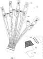
- sensor trace patternsare formed on the stretchable material of a sensor glove 300 that may be used, for example, to translate a human's hand motions and the hand's interactions with the physical world into a virtual representation of the hand (or some other virtual object) and its interactions in a virtual environment.
- the hand's motions and interactionsmay be used to control a robotic hand or device in the physical world.
- the material on which the trace patterns are formedmay be a flexible piezoresistive material or a flexible dielectric material. Again, in the latter case, a flexible piezoresistive material is tightly integrated with the flexible substrate on which the trace patterns are formed and in contact with the trace patterns at the various sensor locations (i.e., S 1 -S 19 ).
- trace patterns corresponding to some of the sensorsare placed to coincide with various joints of the fingers (e.g., knuckles or finger joints) to capture distortion and/or deformation of the glove in response to bending and flexing of those joints.
- Other sensorse.g., S 6 -S 13 and S 19
- Other sensorsmay also be placed on the palm of the glove and/or the tips of the fingers to detect bending and flexing forces as well as forces relating, for example, to touching, gripping, or otherwise coming into contact with objects or surfaces.
- Portions of the conductive traces that are not intended to be part of a sensormay be shielded or insulated to reduce any unwanted contributions to the sensor signals. That is, the portions of the conductive traces that bring the drive and sense signals to and from the sensors may be insulated from the piezoresistive material using, for example, a dielectric or non-conducting material between the piezoresistive material and the conductive traces. According to some implementations in which the conductive traces are formed on a flexible dielectric material, isolated pieces of piezoresistive material may be selectively located at the respective sensor locations.
- each of the sensorsincludes two adjacent traces, the respective patterns of which include extensions that alternate. See, for example, the magnified view of sensor S 4 .
- One of the traces 301receives a drive signal; the other trace 302 transmits the sensor signal to associated sensor circuitry (not shown).
- the drive signalmight be provided, for example, by connecting the trace (permanently or temporarily) to a voltage reference, a signal source that may include additional information in the drive signal, a GPIO (General Purpose Input Output) pin of an associated processor or controller, etc. And as shown in the example in FIG.
- the sensor signalmight be generated using a voltage divider in which one of the resistors of the divider includes the resistance between the two traces through the intervening piezoresistive material.
- the other resistor(represented by R 1 ) might be included, for example, with the associated sensor circuitry.
- the sensor signalAs the resistance of the piezoresistive material changes with applied force or pressure, the sensor signal also varies as a divided portion of the drive signal.
- the sensorsare energized (via the drive signals) and interrogated (via the sensor signals) to generate an output signal for each that is a representation of the force exerted on that sensor.
- the sensorsare energized (via the drive signals) and interrogated (via the sensor signals) to generate an output signal for each that is a representation of the force exerted on that sensor.
- implementationsare contemplated having more or fewer sensors.
- different sets of sensorsmay be selectively energized and interrogated thereby reducing the number and overall area of traces on the substrate, as well as the required connections to sensor circuitry on an associated PCB (which may be positioned, for example, in cutout 322 ).
- the 19 sensorsare driven via 11 drive signal outputs from the sensor circuitry (not shown), and the sensor signals are received via 2 sensor signal inputs to the sensor circuitry; with 13 connections between the flexible substrate on which the conductive traces are formed and the PCB in cutout 322 as shown.
- the set of sensors providing sensor signals to one of the 2 sensor signal inputsmay be energized in any suitable sequence or pattern such that any signal received on the corresponding sensor signal input can be correlated with the corresponding sensor drive signal by the sensor circuitry.
- the sensor signals in this implementationare received by the sensor circuitry via two different sensor signal inputs, two sensors can be simultaneously energized as long as they are connected to different sensor signal inputs to the sensor circuitry.
- Thisallows for the sharing of drive signal lines.
- eight pairs of sensorsshare a common drive signal line, i.e., S 2 and S 8 , S 3 and S 10 , S 4 and S 12 , S 6 and S 14 , S 7 and S 15 , S 9 and S 16 , S 11 and S 17 , and S 13 and S 19 .
- the sharing of the common drive signal linesmay be enabled by insulators which allow the conductive traces to cross, as well as locations at which the conductive traces simply diverge. Other suitable variations on this theme will be understood by those of skill in the art to be within the scope of this disclosure.
- a PCBmay be connected to the conductive traces of the sensor array as described U.S. patent application Ser. No. 14/671,821 entitled Flexible Sensors and Applications filed on Mar. 27, 2015, the entire disclosure of which is incorporated herein by reference for all purposes.
- any of a variety of techniquesmay be employed to make such a connection including, for example, elastomeric connectors (e.g., ZEBRA® connectors) which alternate conductive and non-conductive rubber at a density typically an order of magnitude greater than the width of the conductive traces to which they connect (e.g., at the edge of the fabric).
- elastomeric connectorse.g., ZEBRA® connectors
- ZEBRA® connectorsalternate conductive and non-conductive rubber at a density typically an order of magnitude greater than the width of the conductive traces to which they connect (e.g., at the edge of the fabric).
- a variety of other suitable alternativesare available to those of skill in the art.
- FIG. 4is a simplified diagram of sensor circuitry that may be provided on a PCB for use with implementations described herein.
- such sensor circuitrycould be provided on a PCB in cutout 322 and connected to the conductive traces associated with sensors S 1 -S 19 .
- a resulting signal(captured via the corresponding traces) is received and digitized (e.g., via multiplexer 402 and A-D converter 404 ) and may be processed locally (e.g., by processor 406 ) and/or transmitted to a connected device (e.g., via a Bluetooth or other wireless connection, or even via a USB connection).
- a connected devicee.g., via a Bluetooth or other wireless connection, or even via a USB connection.
- the sensorsmay be selectively energized by the sensor circuitry (e.g., under the control of processor 406 via D-A converter 408 and multiplexer 410 ) to effect the generation of the sensor signals.
- the C8051F380-GM controller(provided by Silicon Labs of Austin, Tex.) is an example of a processor suitable for use with various implementations.
- powermay be provided to the sensor circuitry via a USB connection.
- systems that transmit data wirelesslymay provide power to the sensor circuitry using any of a variety of mechanisms and techniques including, for example, using one or more batteries, solar cells, and/or mechanisms that harvest mechanical energy.
- the LTC3588(provided by Linear Technology Corporation of Milpitas, Calif.) is an example of an energy harvesting power supply that may be used with at least some of these diverse energy sources.
- Other suitable variationswill be appreciated by those of skill in the art.
- the sensor circuitry shown in FIG. 4is merely an example. A wide range of sensor circuitry components, configurations, and functionalities are contemplated.
- conductive tracescan be formed on one or both sides of a flexible substrate.
- two-sided implementationsmay require some mechanism for connecting conductive traces on one side of the substrate to those on the other side.
- Some implementationsuse vias in which conductive ink or paint is flowed through the vias to establish the connections.
- metal vias or rivetsmay make connections through the substrate.
- FIG. 5illustrates the use of vias or rivets through the flexible substrate (e.g., configuration 502 ), and the use of insulating materials to insulate conductive traces from the substrate where the substrate is a piezoresistive material (e.g., configuration 504 ).
- Such mechanismsenable complex patterns of traces and routing of signals in a manner analogous to the different layers of a PCB.
- conductive traces that transmit signals to and from the sensors of glove 300may be insulated from the underlying piezoresistive substrate by an insulating material. This is most clearly illustrated in the figure by insulators 304 and 306 that are associated with the drive and sense signal lines connected to sensor S 4 .
- sense signal lines from multiple sensorsare connected to each other on the opposite side (not shown) of the material depicted in FIG. 3 through the use of vias at locations 310 - 318 .
- sensor trace patternsmay be placed in a roughly cylindrical configuration around the wrist to detect bending of the wrist in two dimensions (e.g., up, down, left, right). When all four sensors register a similar response, this could mean that the wrist is twisting. However, this configuration may not provide sufficient information to determine the direction of the twist. Therefore, according to a particular implementation, an outer cylinder 608 may be attached to an inner cylinder 610 with at least two stretch sensors (e.g., 612 and 614 ). By comparison of the outputs of these stretch sensors, the direction (e.g., 616 ) as well as the amount of the rotation can be captured.
- stretch sensorse.g., 612 and 614
- FIG. 7illustrates particular class of implementations of a sensor array 700 for use in a sensor glove in which conductive traces are formed on a flexible dielectric substrate 702 . Operation of sensor array 700 is similar to operation of the sensor array of sensor glove 300 as described above. And it should be noted that the depicted configuration of traces might also be included in implementations in which the traces are formed on piezoresistive material.
- substrate 702may be constructed from a thermoplastic polyurethane (TPU) material such as, for example, Products 3415 or 3914 from Bemis Associates Inc. of Shirley, Mass.
- TPUthermoplastic polyurethane
- the conductive tracesmay be screen printed on the substrate using a conductive flexible ink such as, for example, conductive silicone-based inks manufactured by E.I. du Pont de Nemours and Company (DuPont) of Wilmington, Del., or Creative Materials of Ayer, Mass.
- Patches of a piezoresistive materiale.g., the Eeonyx fabric discussed above
- a second substrate of the TPU material(not shown) is placed over array 700 , and the assembly is heated to thermally bond the components together, fixing the piezoresistive patches in contact with their respective sensor traces.
- FIG. 8shows a flexible substrate 802 on which a conductive trace 804 is formed. Piezoresistive material 806 is maintained in contact with trace 804 by a second flexible substrate 808 .
- substrates 802 and 808are TPU substrates and trace 804 is a conductive ink that is screen printed on TPU substrate 802 .
- TPU substrate 802has an adhesive-barrier-adhesive (ABA) structure that allows for the assembly to be thermally bonded (e.g., melted) to another substrate such as, for example, a fabric glove blank 900 as depicted in FIG. 9 .
- the other TPU substrate 808is shown an adhesive-barrier (AB) structure so that it only bonds to the assembly.
- this substratehas an ABA structure to enable thermal bonding on both sides of the assembly.
- stiffenersmay be placed in alignment with at least some of the piezoresistive patches and the corresponding trace patterns for the purpose of amplifying the signals generated by the corresponding sensors, e.g., by the force of the stiffener resisting bending of a knuckle and compressing the piezoresistive material.
- a stiffenermight be a plastic film (e.g., polyethylene terephthalate or PET).
- a stiffenermay be another piece of fabric.
- a stiffening materialsuch as DuPont 5036 Dielectric ink may be silk-screened or printed on one of the components of the stack.
- stiffenersmay be inserted at any point in the stack of materials (e.g., as depicted in FIG. 8 ) as long as the electrical connection between the conductive traces and the piezoresistive material is not unduly degraded.
- a stiffener 706(e.g., of PET or other suitable material) may be adhered to substrate 702 near the terminations of the conductive traces to allow for the insertion of the assembly into a connector 708 (see the exploded view in the lower right hand corner of the drawing).
- connector 708is a Molex ZIF flat flex connector such as, for example, the Molex connector 52207-2860 (a 28 position connector) or the Molex connector 0522710869 (an 8 position connector as shown in FIG. 11 ).
- sensor glove implementationsare contemplated in which sensors are placed on the palm of the glove and/or the tips of the fingers to detect, for example, touching, gripping, or otherwise coming into contact with objects or surfaces.
- FIG. 10An example of how such a sensor might be integrated with an array is shown in FIG. 10 .
- flexible substrate 1002extends beyond sensor S 4 and includes a tab 1004 on which the conductive traces of sensor S 15 are formed.
- Tab 1004can be wrapped around inside the glove (as indicated by the arrow) so that it coincides with the fingertip of the glove.
- any forces acting on the fingertip of the glovee.g., by virtue of the fingertip coming into contact with a surface
- such sensorsmay be integrated with a sensor array for the back of the hand as shown in FIG. 10 .
- such sensorsmay be implemented as separate array for the palm and fingertips.
- FIG. 11shows an alternative design for a sensor array 1100 for use in a sensor glove which includes only four elongated sensors; S 1 -S 3 for the three middle fingers, and S 4 for the thumb.
- this simpler designmay be easier and/or cheaper to manufacture and may be sufficient or even more well-suited for some applications than the designs described above with reference to FIGS. 3 and 7 .
- sensor array 1100operates similarly to the sensor arrays described and may be constructed using either approach.
- substrate 1102is constructed from a TPU material and the conductive traces are screen printed on substrate 1102 using a conductive flexible ink as described above with reference to FIGS. 7 and 8 .
- Patches of a piezoresistive materialare placed in contact with the conductive traces at the locations of sensors S 1 -S 4 . See for example, piezoresistive patch 1104 at sensor S 3 .
- a second substrate of the TPU material(not shown) is placed over array 1100 , and the assembly is heated to thermally bond the components together, fixing the piezoresistive patches in contact with their respective sensor traces.
- a stiffener(not shown) may be adhered to substrate 1102 near the terminations of the conductive traces to allow for the insertion of the assembly into a connector 1108 .
- use of the stiffenerallows for connection of sensor array 1100 to any of a wide variety of industry standard connectors including, for example, the Molex connector 0522710869.
- stiffeners(not shown) may be placed in alignment with at least some of the piezoresistive patches and the corresponding trace patterns of sensor array 1100 for the purpose of amplifying the signals generated by the corresponding sensors.
- FIGS. 12-14Cillustrate another class of implementations for use in a sensor glove.
- sensor system 1200includes five digit assemblies 1202 (one for each finger or digit of the hand) and four abductor assemblies 1204 (one for each space between each pair of adjacent digits). These assemblies are connected to a circuit board 1206 on which is implemented the circuitry (not shown) for energizing and reading signals from the knuckle sensors and abductor sensors on each assembly. Digit assemblies 1202 are interconnected via substrate 1208 and abductor assemblies 1204 are interconnected via substrate 1210 . Substrates 1208 and 1210 are secured to opposite sides of circuit board 1206 to form sensor system 1200 .
- Conductors on substrates 1208 and 1210provide connections between conductors on digit assemblies 1202 and abductor assemblies 1204 and corresponding conductors on circuit board 1206 (not shown).
- Sensor system 1200is secured by top enclosure 1209 and ergonomic back plate 1211 and is aligned with the back of a hand inserted in a sensor glove 1300 as illustrated in FIG. 13 .
- Each digit assembly 1202includes two knuckle sensors, each knuckle sensor being formed using a strip of piezoresistive material 1212 (e.g., a fabric) in contact with a group of sensor traces (obscured by material 1212 in FIG. 12 ) on the surface of a flexible dielectric substrate 1214 .
- Routing traces 1216 by which signals are transmitted to and received from the individual sensorsare adjacent the opposite surface of substrate 1214 from the sensor trace groups (i.e., the underside of substrate 1214 in the figure). Routing traces 1216 are connected to the sensor traces through substrate 1214 , e.g., using vias.
- Substrate 1214is depicted as being transparent so that routing traces 1216 on its underside are at least partially visible.
- Each knuckle sensorgenerates a sensor signal that represents the degree of bend in the corresponding knuckle.
- Each abductor assembly 1204includes one abductor sensor formed using a strip of piezoresistive material 1218 (only one of which is shown in FIG. 12 ), e.g., a fabric, in contact with a group of sensor traces 1219 (one set of which is obscured by material 1218 ) on the surface of a flexible dielectric substrate 1220 .
- Routing traces(not shown) by which signals are transmitted to and received from the abductor sensor are adjacent the opposite surface of substrate 1220 from the sensor trace group (i.e., the underside of substrate 1220 in the figure).
- the routing tracesare connected to sensor traces 1219 through substrate 1220 , e.g., using vias.
- Each abductor sensorgenerates a sensor signal that represents the spread angle between two adjacent digits.
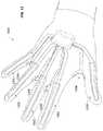
- the orientation of sensor system 1200 within a glovemay be understood with reference to FIG. 13 .
- each digit assembly 1302extends along the back of the glove and along one of the corresponding fingers (referring to the thumb as one of the fingers).
- the degree of bend of its knucklesare represented by the sensor signals generated by the corresponding knuckle sensors.
- the portion of each abductor assembly 1304 including the abductor sensoris bent back on itself almost 180 degrees (e.g., like a taco shell or a “v”) with the center line of the bend being aligned with the crux of the two corresponding adjacent digits.
- the abductor sensoris considered to be “at rest” in this position.
- the abductor sensorflattens out and stretches, generating a corresponding sensor signal representing the spread angle.
- each of the sensorsmay be energized and interrogated as described above with reference to FIG. 3 using sensor circuitry such as that described with reference to FIG. 4 . That is, each of the sensors includes two traces. One of the traces receives a drive signal, and the other transmits the sensor signal to the sensor circuitry. As discussed above, the sensor signal may be generated using a voltage divider in which one of the resistors of the divider includes the resistance between the two traces through the intervening piezoresistive material, and the other is included with the sensor circuitry. As the resistance of the piezoresistive material changes with applied force or pressure, the sensor signal also varies as a divided portion of the drive signal.
- calibrated sensor dataare stored (e.g., in memory 407 of processor 406 ) that represent the response of each of the sensors. Such data ensure consistency and accuracy in the way the sensor outputs are processed and used to represent the motion and articulation of the parts of the hand.
- the output of each sensore.g., as captured by ADC 404
- ADC 404the output of each sensor is measured for a range of known input forces corresponding to specific positions of the hand.
- a set of data points for each sensoris captured (e.g., in a table in memory 407 ) associating ADC values with corresponding finger positions.
- the data set for each sensormay capture a value (or an offset value) for many (or even every) of the possible values of the ADC output. Alternatively, fewer data points may be captured and the sensor circuitry may use interpolation to derive force values for ADC outputs not represented in the data set.
- the calibration data for each abductor sensorrepresent a range of the spread of the corresponding pair of fingers with a range of data values.
- the calibration data for each knuckle sensorrepresent a range of the bend of the corresponding knuckle with a range of data values.
- calibrationinvolves holding the hand in various positions and storing data values for those positions. For example, the user might be instructed (e.g., in a video or animation) to hold her hand out relaxed with the fingers together, make a fist, spread the fingers out, etc. Data values for each sensor may then be captured for each position.
- the calibration datacapture two positions of the range for each sensor. These positions may be, for example, at the extreme ends of each range. For example, for an abductor sensor, the two positions might be (1) the pair of fingers together and (2) the pair of fingers spread apart as far as possible. Similarly, for a knuckle sensor, the two positions might be (1) the knuckle straight and (2) the knuckle bent as far as possible. Interpolation (e.g., linear interpolation) is then used at run time to determine positions in the range between the extremes for each knuckle and abductor sensor.
- Interpolatione.g., linear interpolation
- These calibration datacan be stored across sessions. And because such data can be user-specific, this might include the storing of multiple sets; one for each unique user. Alternatively, the calibration data can be regenerated for each session, e.g., by running the user through the various hand positions of the calibration routine.
- the sensor circuitry on circuit board 1206includes an inertial measurement unit (IMU) (not shown) that includes a 3-axis accelerometer, a 3-axis gyroscope, and a 3-axis magnetometer.
- IMUinertial measurement unit
- the information from these componentsis blended by the IMU to give the attitude of the hand, i.e., pitch, roll, and yaw.
- Translationi.e., movement of the hand in x, y, and z, may be tracked using one or more cameras (e.g., gaming system cameras), one or more ultrasonic sensors, one or more electromagnetic sensors, etc., to determine the position of the glove in space.
- the position, attitude, and finger articulations of the user's handcan be captured.
- An example of an IMU that may be employed with various implementationsis the BNO055 provided by Bosch Sensortec GmbH of Reutlingen/Kusterdingen, Germany.
- Other examples of suitable IMUsare provided by InvenSense, Inc. of San Jose, Calif., and ST Microelectronics of Geneva, Switzerland.
- each digit assemblyalso includes a haptic actuator (not shown for clarity) which is connected to its own set of routing traces (partially visible) via pads 1224 .
- the haptic actuatorsare aligned with each fingertip for the purpose of creating the sensation that the fingertip is in contact with an object or a surface (e.g., in a virtual space or at a remote location) thereby giving the user a sense of feel. Because sensor system 1200 is aligned with the back of the hand, the haptic actuators are connected to pads 1224 via conductors (not shown) that wrap around the finger.
- each actuatoris a flexible metal membrane (e.g., a kapton-mylar film) stretched over a rigid substrate.
- the membraneshrinks or expands based on a voltage applied by the sensor circuitry via pads 1224 .
- the haptic actuatorscan be thought of as tiny “speakers” that are driven with different waveforms to simulate different surfaces, signaling that the fingers have contacted something in the virtual world or at the remote location.
- the waveforms for these contact eventsdepend on the nature of the surface being simulated, the number of fingertips contacting the surface, the rate of movement across the virtual surface, etc. In some cases, accompanying audio may be provided to enhance the perception of the contact. Examples of haptic actuators that may be used with various implementations include those provided by Novasentis Inc. of Berkeley, Calif.
- FIGS. 14A-14Cshow a stack of components of a sensor system that includes the knuckle sensors and haptic actuators.
- the components relating to the abductor sensorsare not shown for clarity. However, it will be understood that the abductor assemblies may be formed similarly to the depicted digit assemblies in terms of the materials and the ordering of the components (without the components relating to the haptic actuators).
- ergonomic back plate 1402is shown at the bottom of the stack relative to the orientation of the figure.
- Back plate 1402has a curved surface that conforms to the back of the user's hand.
- Haptic bus lines 1404(for connection to the haptic actuators which are not shown) are printed with conductive ink on one side of PET substrate 1406 .
- Sensor bus lines 1408(including pads for connection to the sensor circuitry circuit board) that are used to energize and read signals from each of the knuckle sensors are printed with conductive ink on the other side of PET substrate 1406 .
- PET substrates 1410are placed over sensor bus lines 1408 and PET substrate 1406 .
- Sensor traces 1412(including some traces to connect to the bus lines) are printed in conductive ink on PET substrates 1410 (and partially on PET substrate 1406 to connect with bus lines 1408 ).
- Each parallel pair of traces (e.g., 1413 ) on PET substrates 1410corresponds to a knuckle sensor.
- a carbon passivation layer 1414is printed over sensor traces 1412 , and exposed portions of bus lines 1408 to protect the conductive traces from tarnishing and creeping. Dielectric strips may be placed over portions of the bus traces to insulate them from the sensor traces and the piezoresistive material.
- piezoresistive fabric strips 1416are placed in contact with each pair of sensor traces 1412 to form the knuckle sensors.
- Each fabric strip 1416has a PET strip 1418 applied as a stiffener that is secured using pressure sensitive adhesive (PSA) 1420 .
- PET 1418makes fabric 1416 asymmetrically stiffer, resisting the bend of the fabric, causing it to distort, thereby enhancing the bend signal and helping to achieve the desired sensor response and dynamic range.
- PSApressure sensitive adhesive
- TPU strips 1422are placed over the knuckle sensors and heated to thermally bond the components together, fixing the piezoresistive strips in contact with their respective sensor traces.
- sensor traces 1412are printed such that portions of the sensor traces are on PET substrates 1410 and other portions are contacting and connecting with bus lines 1408 on the underlying PET substrate 1406 . Connections between sensor traces 1412 and bus lines 1408 may also be made through PET substrate 1406 , e.g., using vias. And although the knuckle sensors are depicted as using two parallel traces other trace group configurations are contemplated. For example, sensor traces having interdigitated extensions are employed with some implementations as discussed above. Another example of such an implementation is shown in FIGS. 15 and 16 .
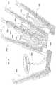
- FIG. 15shows the sensor traces and bus lines of a sensor system 1500 without other layers and components so as not to obscure details of these structures.
- Each of the five digit assemblies 1502includes four knuckle sensors 1504 as indicated on the digit assembly corresponding to the middle finger. Having two sensors per knuckle may allow for finer detection and/or representation of motion.
- Four abductor assemblies 1506are also shown.
- bus lines 1602(which include both sensor and haptic bus lines) are printed in conductive ink on one side of a TPU substrate 1604 .
- Sensor traces 1606are printed in conductive ink on the other side of TPU substrate 1604 and connected to the corresponding bus lines through TPU substrate 1604 , e.g., using vias.
- This assemblyis then placed in contact with piezoresistive fabric, e.g., in the shape of a glove blank (not shown). These components are then heated, securing the sensor traces 1606 to the piezoresistive fabric from which a sensor glove is then made.
- Abductor assemblies 1608(of which only the traces are shown) may be similarly constructed. Alternatively, because of their relatively simple structures, abductor assemblies 1608 may be formed on the piezoresistive fabric, e.g., printed using conductive ink and insulators (for the bus lines extending to and from the abductor sensors).
- the applications for sensor gloves enabled by the present disclosureare numerous and diverse.
- the action of a human hand in such a sensor glovemay be translated to control systems, devices, and processes in both the real and virtual worlds.
- a humancan interact with objects in a virtual space, having utility in video and online gaming, as well as educational and artistic applications.
- a sensor glovemay be used to simulate a surgical procedure, playing of a virtual musical instrument, conducting of a virtual orchestra, painting of a virtual work of art, etc.
- Translation of the movements of a human hand into the virtual worldcould support more realistic computer aided animation.
- Industrial applicationsmight include remote control of manufacturing apparatus or robotics handling hazardous materials. As will be appreciated from the diversity of these examples, the range of applications is virtually limitless. The scope of this disclosure should therefore not be limited by reference to specific applications.
Landscapes
- Engineering & Computer Science (AREA)
- Physics & Mathematics (AREA)
- General Physics & Mathematics (AREA)
- Health & Medical Sciences (AREA)
- Life Sciences & Earth Sciences (AREA)
- Theoretical Computer Science (AREA)
- General Engineering & Computer Science (AREA)
- Molecular Biology (AREA)
- Public Health (AREA)
- Medical Informatics (AREA)
- Biomedical Technology (AREA)
- Surgery (AREA)
- Animal Behavior & Ethology (AREA)
- General Health & Medical Sciences (AREA)
- Heart & Thoracic Surgery (AREA)
- Veterinary Medicine (AREA)
- Pathology (AREA)
- Biophysics (AREA)
- Human Computer Interaction (AREA)
- Chemical & Material Sciences (AREA)
- Analytical Chemistry (AREA)
- Force Measurement Appropriate To Specific Purposes (AREA)
- User Interface Of Digital Computer (AREA)
Abstract
Description
Claims (46)
Priority Applications (1)
| Application Number | Priority Date | Filing Date | Title |
|---|---|---|---|
| US15/986,649US11147510B2 (en) | 2014-06-09 | 2018-05-22 | Flexible sensors and sensor systems |
Applications Claiming Priority (6)
| Application Number | Priority Date | Filing Date | Title |
|---|---|---|---|
| US14/299,976US9965076B2 (en) | 2014-05-15 | 2014-06-09 | Piezoresistive sensors and applications |
| US201462072798P | 2014-10-30 | 2014-10-30 | |
| US14/671,821US9753568B2 (en) | 2014-05-15 | 2015-03-27 | Flexible sensors and applications |
| US14/928,058US9710060B2 (en) | 2014-06-09 | 2015-10-30 | Sensor system integrated with a glove |
| US15/621,935US10362989B2 (en) | 2014-06-09 | 2017-06-13 | Sensor system integrated with a glove |
| US15/986,649US11147510B2 (en) | 2014-06-09 | 2018-05-22 | Flexible sensors and sensor systems |
Related Parent Applications (1)
| Application Number | Title | Priority Date | Filing Date |
|---|---|---|---|
| US15/621,935ContinuationUS10362989B2 (en) | 2014-06-09 | 2017-06-13 | Sensor system integrated with a glove |
Publications (2)
| Publication Number | Publication Date |
|---|---|
| US20180263563A1 US20180263563A1 (en) | 2018-09-20 |
| US11147510B2true US11147510B2 (en) | 2021-10-19 |
Family
ID=60088637
Family Applications (2)
| Application Number | Title | Priority Date | Filing Date |
|---|---|---|---|
| US15/621,935ActiveUS10362989B2 (en) | 2014-06-09 | 2017-06-13 | Sensor system integrated with a glove |
| US15/986,649Active2034-07-18US11147510B2 (en) | 2014-06-09 | 2018-05-22 | Flexible sensors and sensor systems |
Family Applications Before (1)
| Application Number | Title | Priority Date | Filing Date |
|---|---|---|---|
| US15/621,935ActiveUS10362989B2 (en) | 2014-06-09 | 2017-06-13 | Sensor system integrated with a glove |
Country Status (1)
| Country | Link |
|---|---|
| US (2) | US10362989B2 (en) |
Cited By (5)
| Publication number | Priority date | Publication date | Assignee | Title |
|---|---|---|---|---|
| US20220175317A1 (en)* | 2018-12-14 | 2022-06-09 | Siren Care, Inc. | Sensing garment and method for making same |
| US11480481B2 (en) | 2019-03-13 | 2022-10-25 | Bebop Sensors, Inc. | Alignment mechanisms sensor systems employing piezoresistive materials |
| US11633847B2 (en)* | 2019-04-11 | 2023-04-25 | Massachusetts Institute Of Technology | Sensing and control systems |
| US11891730B2 (en) | 2016-09-27 | 2024-02-06 | Siren Care, Inc. | Smart yarn and method for manufacturing a yarn containing an electronic device |
| US12310700B2 (en) | 2015-12-16 | 2025-05-27 | Siren Care, Inc. | System and method for detecting inflammation in a foot |
Families Citing this family (48)
| Publication number | Priority date | Publication date | Assignee | Title |
|---|---|---|---|---|
| JP5621090B2 (en) | 2009-10-16 | 2014-11-05 | ビーボップ センサーズ、インコーポレイテッド | Foot-operated controller and computer-implemented method |
| US11327599B2 (en) | 2011-04-26 | 2022-05-10 | Sentons Inc. | Identifying a contact type |
| US11262253B2 (en) | 2017-08-14 | 2022-03-01 | Sentons Inc. | Touch input detection using a piezoresistive sensor |
| EP2780783B1 (en) | 2011-11-18 | 2022-12-28 | Sentons Inc. | Detecting touch input force |
| US9076419B2 (en) | 2012-03-14 | 2015-07-07 | Bebop Sensors, Inc. | Multi-touch pad controller |
| US11304628B2 (en) | 2013-09-17 | 2022-04-19 | Medibotics Llc | Smart clothing with dual inertial sensors and dual stretch sensors for human motion capture |
| US11071498B2 (en) | 2013-09-17 | 2021-07-27 | Medibotics Llc | Smart clothing with inertial, strain, and electromyographic sensors for human motion capture |
| US11892286B2 (en) | 2013-09-17 | 2024-02-06 | Medibotics Llc | Motion recognition clothing [TM] with an electroconductive mesh |
| US9965076B2 (en) | 2014-05-15 | 2018-05-08 | Bebop Sensors, Inc. | Piezoresistive sensors and applications |
| US9442614B2 (en) | 2014-05-15 | 2016-09-13 | Bebop Sensors, Inc. | Two-dimensional sensor arrays |
| US9753568B2 (en) | 2014-05-15 | 2017-09-05 | Bebop Sensors, Inc. | Flexible sensors and applications |
| US10362989B2 (en) | 2014-06-09 | 2019-07-30 | Bebop Sensors, Inc. | Sensor system integrated with a glove |
| US9863823B2 (en) | 2015-02-27 | 2018-01-09 | Bebop Sensors, Inc. | Sensor systems integrated with footwear |
| US10082381B2 (en) | 2015-04-30 | 2018-09-25 | Bebop Sensors, Inc. | Sensor systems integrated with vehicle tires |
| US9827996B2 (en) | 2015-06-25 | 2017-11-28 | Bebop Sensors, Inc. | Sensor systems integrated with steering wheels |
| US10422637B1 (en)* | 2016-06-10 | 2019-09-24 | Facebook Technologies, Llc | Wave reflection deformation sensing apparatus |
| US10481688B1 (en)* | 2016-09-19 | 2019-11-19 | Apple Inc. | Finger beam for generating haptic feedback |
| WO2019018702A1 (en)* | 2017-07-19 | 2019-01-24 | Plexus Immersive Corp | Hand worn interface device |
| US11580829B2 (en) | 2017-08-14 | 2023-02-14 | Sentons Inc. | Dynamic feedback for haptics |
| TWI642421B (en)* | 2018-01-05 | 2018-12-01 | 富伯生醫科技股份有限公司 | Finger motion sensing gloves capable of fixing sensors |
| CN110582740B (en) | 2018-01-19 | 2023-07-25 | 株式会社感知合一 | Soft sensor and manufacturing method thereof, hand-worn device having soft sensor and manufacturing method thereof |
| KR101998250B1 (en)* | 2018-01-30 | 2019-07-11 | 주식회사 필더세임 | Soft sensor and manufacturing method of the same |
| EP3518075B1 (en)* | 2018-01-24 | 2023-10-11 | C.R.F. Società Consortile per Azioni | Sensorized glove and corresponding method for ergonomic analysis of the hand, in particular a worker's hand |
| EP3518076B1 (en)* | 2018-01-24 | 2022-09-14 | C.R.F. Società Consortile per Azioni | System and method for ergonomic analysis, in particular of a worker |
| KR102608694B1 (en) | 2018-04-18 | 2023-12-04 | 삼성전자 주식회사 | Electronic device comprising phase retarder and polarizing element for blocking out light reflected by sensor disposed below display thereof |
| CN108986777A (en)* | 2018-06-14 | 2018-12-11 | 森兰信息科技(上海)有限公司 | Method, somatosensory device and the musical instrument terminal of music simulation are carried out by body-sensing |
| US10884496B2 (en) | 2018-07-05 | 2021-01-05 | Bebop Sensors, Inc. | One-size-fits-all data glove |
| IT201800007012A1 (en)* | 2018-07-13 | 2020-01-13 | Vincenzo Stornelli | Sensory glove with energy recovery system |
| US20220053637A1 (en)* | 2018-09-21 | 2022-02-17 | Bioserenity | Textile device configured to cooperate with an electronic device |
| CN109613976B (en)* | 2018-11-14 | 2023-08-22 | 华东师范大学 | Intelligent flexible pressure sensing sign language recognition device |
| US10890970B2 (en) | 2018-12-24 | 2021-01-12 | Lasarrus Clinic And Research Center | Flex force smart glove for measuring sensorimotor stimulation |
| EP3911407A1 (en) | 2019-01-16 | 2021-11-24 | Palmm Co. | Devices, systems, and methods for delivering electrical current to the body |
| US11041772B2 (en)* | 2019-03-25 | 2021-06-22 | Toyota Motor Engineering & Manufacturing North America, Inc. | Sensor diffusion stack materials for pressure sensing gloves and methods incorporating the same |
| US11860052B2 (en) | 2019-12-19 | 2024-01-02 | Toyota Motor Engineering & Manufacturing North America, Inc. | Pressure distribution and localization detection methods and apparatuses incorporating the same |
| US10952672B2 (en) | 2019-12-19 | 2021-03-23 | Toyota Motor Engineering & Manufacturing North America, Inc. | Pressure management methods for determining non-inclusive forces and apparatuses incorporating the same |
| KR102353978B1 (en)* | 2020-05-28 | 2022-01-24 | 주식회사 네오펙트 | Hand rehabilitation training apparatus |
| JP7424926B2 (en)* | 2020-06-26 | 2024-01-30 | 株式会社日立製作所 | digitization system |
| GB202013393D0 (en) | 2020-08-26 | 2020-10-07 | Elias Hugo | A device for connecting motion tracking sensors to a hand |
| US12055449B2 (en)* | 2020-08-28 | 2024-08-06 | Board Of Trustees Of Michigan State University | Flexible sensor |
| WO2022060579A1 (en) | 2020-09-16 | 2022-03-24 | Leibowitz Ian | Method and apparatus for sanitization of hand coverings |
| US11609636B2 (en) | 2020-12-14 | 2023-03-21 | Jonathan P. Nieman | Virtual reality glove |
| EP4067849A1 (en)* | 2021-03-31 | 2022-10-05 | ETH Zurich | Sensor system for a three-dimensional device |
| AT525209A1 (en)* | 2021-06-28 | 2023-01-15 | Sendance Gmbh | sensor network |
| KR20230066988A (en)* | 2021-11-08 | 2023-05-16 | 주식회사 비햅틱스 | Tactile stimulation providing device |
| WO2024064677A1 (en)* | 2022-09-21 | 2024-03-28 | Hollister Incorporated | Sensors for monitoring bladder pressure |
| CN115901610A (en)* | 2022-11-11 | 2023-04-04 | 清华大学 | Vinasse detection system and method based on flexible touch sensor |
| CN115582842B (en)* | 2022-12-02 | 2023-03-07 | 浙江大学 | Manipulator gripping control system and method with flexible touch sensor |
| FR3144345B1 (en)* | 2022-12-22 | 2025-04-04 | Commissariat Energie Atomique | HAPTIC FEEDBACK GLOVE FOR PERSONAL COMMUNICATION |
Citations (313)
| Publication number | Priority date | Publication date | Assignee | Title |
|---|---|---|---|---|
| US4294014A (en) | 1979-03-27 | 1981-10-13 | Bidegain S.A. | Apparatus for determining the shoe size corresponding to a foot |
| US4438291A (en) | 1982-03-08 | 1984-03-20 | General Electric Company | Screen-printable thermocouples |
| EP0014022B1 (en) | 1979-01-25 | 1984-11-14 | Technisch Advies- en Handelsbureau Hoogstraat C.V. | Foot-size measuring apparatus |
| US4489302A (en) | 1979-09-24 | 1984-12-18 | Eventoff Franklin Neal | Electronic pressure sensitive force transducer |
| US4515404A (en) | 1982-01-21 | 1985-05-07 | Nissan Motor Company, Limited | Seat sliding device |
| EP0211984A1 (en) | 1985-08-19 | 1987-03-04 | Inc. Vpl Research | Computer data entry and manipulation apparatus |
| US4693530A (en) | 1986-09-29 | 1987-09-15 | Amp Incorporated | Shielded elastomeric electric connector |
| US4734034A (en)* | 1985-03-29 | 1988-03-29 | Sentek, Incorporated | Contact sensor for measuring dental occlusion |
| US4745301A (en) | 1985-12-13 | 1988-05-17 | Advanced Micro-Matrix, Inc. | Pressure sensitive electro-conductive materials |
| US4790968A (en) | 1985-10-19 | 1988-12-13 | Toshiba Silicone Co., Ltd. | Process for producing pressure-sensitive electroconductive sheet |
| US4852443A (en) | 1986-03-24 | 1989-08-01 | Key Concepts, Inc. | Capacitive pressure-sensing method and apparatus |
| NL8900820A (en) | 1989-04-04 | 1990-11-01 | Hoogstraat Med Tech | Automatic shoe size measuring appts. - measures both inside and outside dimensions using sensors supplying microprocessor |
| US5033291A (en)* | 1989-12-11 | 1991-07-23 | Tekscan, Inc. | Flexible tactile sensor for measuring foot pressure distributions and for gaskets |
| US5079949A (en) | 1990-07-06 | 1992-01-14 | Enix Corporation | Surface pressure distribution detecting element |
| JPH0411666A (en) | 1990-04-27 | 1992-01-16 | Toshiba Silicone Co Ltd | Silicone ink |
| US5128880A (en) | 1990-05-11 | 1992-07-07 | Foot Image Technology, Inc. | Foot measurement and footwear sizing system |
| US5131306A (en) | 1989-01-19 | 1992-07-21 | Yamaha Corporation | Automatic music playing piano |
| US5159159A (en) | 1990-12-07 | 1992-10-27 | Asher David J | Touch sensor and controller |
| US5219292A (en) | 1992-04-03 | 1993-06-15 | Motorola, Inc. | Printed circuit board interconnection |
| US5237520A (en) | 1990-05-11 | 1993-08-17 | Foot Image Technology, Inc. | Foot measurement and footwear sizing system |
| US5288938A (en) | 1990-12-05 | 1994-02-22 | Yamaha Corporation | Method and apparatus for controlling electronic tone generation in accordance with a detected type of performance gesture |
| US5316017A (en) | 1992-10-07 | 1994-05-31 | Greenleaf Medical Systems, Inc. | Man-machine interface for a joint measurement system |
| JPH06323929A (en) | 1993-05-13 | 1994-11-25 | Gunze Ltd | Wearing-pressure measuring apparatus |
| US5386720A (en) | 1992-01-09 | 1995-02-07 | Olympus Optical Co., Ltd. | Integrated AFM sensor |
| US5429092A (en) | 1993-02-25 | 1995-07-04 | Mitsubishi Denki Kabushiki Kaisha | Throttle control system |
| JPH0871978A (en) | 1994-06-27 | 1996-03-19 | Olympus Optical Co Ltd | Manipulator |
| JPH08194481A (en) | 1995-01-13 | 1996-07-30 | Roland Corp | Editing method with foot controller |
| US5571973A (en) | 1994-06-06 | 1996-11-05 | Taylot; Geoffrey L. | Multi-directional piezoresistive shear and normal force sensors for hospital mattresses and seat cushions |
| US5578766A (en) | 1994-04-05 | 1996-11-26 | Nec Corporation | Force detector/indicator |
| US5624132A (en) | 1991-04-09 | 1997-04-29 | Trw Vehicle Safety Systems Inc. | Occupant sensing apparatus |
| US5659395A (en) | 1992-06-23 | 1997-08-19 | Footmark, Inc. | Method and apparatus for analyzing feet |
| US5695859A (en) | 1995-04-27 | 1997-12-09 | Burgess; Lester E. | Pressure activated switching device |
| US5729905A (en) | 1995-09-11 | 1998-03-24 | Dwayne L. Mason | Foot measuring apparatus and circuitry to eliminate multiplexes and demultiplexers |
| JPH10198503A (en) | 1996-11-06 | 1998-07-31 | Synaptics Inc | Force detecting touch pad |
| US5822223A (en) | 1997-08-05 | 1998-10-13 | Genovation Inc. | Electronic foot measuring apparatus |
| US5866829A (en) | 1996-12-20 | 1999-02-02 | Pecoraro; Thomas | Pedal rack |
| US5878359A (en) | 1995-06-09 | 1999-03-02 | Nipponsenso Co., Ltd. | Vehicular control device provided with an accelerator detecting device which detects the operation of an accelerator device |
| WO1999020179A1 (en) | 1997-10-23 | 1999-04-29 | Mason, Dwayne, L. | Solid state digital electronic shoe sizer |
| US5943044A (en) | 1996-08-05 | 1999-08-24 | Interlink Electronics | Force sensing semiconductive touchpad |
| US5989700A (en) | 1996-01-05 | 1999-11-23 | Tekscan Incorporated | Pressure sensitive ink means, and methods of use |
| US6032109A (en) | 1996-10-21 | 2000-02-29 | Telemonitor, Inc. | Smart sensor module |
| US6049327A (en) | 1997-04-23 | 2000-04-11 | Modern Cartoons, Ltd | System for data management based onhand gestures |
| US6087930A (en) | 1994-02-22 | 2000-07-11 | Computer Methods Corporation | Active integrated circuit transponder and sensor apparatus for transmitting vehicle tire parameter data |
| US6121869A (en) | 1999-09-20 | 2000-09-19 | Burgess; Lester E. | Pressure activated switching device |
| JP2000267664A (en) | 1999-03-16 | 2000-09-29 | Yamaha Corp | Playing data processing system |
| US6141643A (en) | 1998-11-25 | 2000-10-31 | Harmon; Steve | Data input glove having conductive finger pads and thumb pad, and uses therefor |
| US6155120A (en)* | 1995-11-14 | 2000-12-05 | Taylor; Geoffrey L. | Piezoresistive foot pressure measurement method and apparatus |
| US6215055B1 (en) | 1997-08-06 | 2001-04-10 | Darren Saravis | Foot pedal boards for musical instruments |
| US6304840B1 (en) | 1998-06-30 | 2001-10-16 | U.S. Philips Corporation | Fingerless glove for interacting with data processing system |
| US6331893B1 (en) | 1992-06-23 | 2001-12-18 | Footmark, Inc. | Foot analyzer |
| US6360615B1 (en) | 2000-06-06 | 2002-03-26 | Technoskin, Llc | Wearable effect-emitting strain gauge device |
| US6388556B1 (en) | 2000-09-07 | 2002-05-14 | Fujikura Ltd. | Film pressure sensitive resistor and pressure sensitive sensor |
| US20020078757A1 (en) | 2000-06-30 | 2002-06-27 | Jacqueline Hines | Surface-acoustic-wave pressure sensor and associated methods |
| US6452479B1 (en)* | 1999-05-20 | 2002-09-17 | Eleksen Limited | Detector contructed from fabric |
| US6486776B1 (en) | 1998-04-14 | 2002-11-26 | The Goodyear Tire & Rubber Company | RF transponder and method of measuring parameters associated with a monitored object |
| US6490515B1 (en) | 1999-01-27 | 2002-12-03 | The Furukawa Electric Co., Ltd. | Passenger detecting apparatus |
| US6531951B2 (en) | 1998-09-11 | 2003-03-11 | I.E.E. International Electronics & Engineering S.A.R.L. | Force sensor |
| US6609054B2 (en) | 2000-05-10 | 2003-08-19 | Michael W. Wallace | Vehicle occupant classification system and method |
| US6626046B2 (en) | 2000-10-30 | 2003-09-30 | Denso Corporation | Pressure-sensitive resistor sensor having electrodes with reduced contact resistance deviation |
| DE10212023A1 (en) | 2002-03-19 | 2003-10-02 | Bosch Gmbh Robert | Sensor cell, especially for use in the sensor mat of a motor vehicle seat, has a piezoelectric resistance element with at least one additional contact so that two resistance measurements are made |
| US6687523B1 (en) | 1997-09-22 | 2004-02-03 | Georgia Tech Research Corp. | Fabric or garment with integrated flexible information infrastructure for monitoring vital signs of infants |
| US20040031180A1 (en)* | 2002-06-17 | 2004-02-19 | Dentcho Ivanov | Sensor array for unauthorized user prevention device |
| US20040060427A1 (en) | 2002-09-30 | 2004-04-01 | Franco Vince De | Electronic percussion instrument with impact position-dependent variable resistive switch |
| US20040093746A1 (en) | 2000-08-18 | 2004-05-20 | Salvatore Varsallona | System for measuring the correct size of shoes |
| US20040118619A1 (en) | 2002-12-19 | 2004-06-24 | Delphi Technologies, Inc. | Seat foam humidity compensation for vehicle seat occupant weight detection system |
| US6763320B2 (en) | 2002-08-15 | 2004-07-13 | International Business Machines Corporation | Data input device for individuals with limited hand function |
| US20040183648A1 (en) | 2003-03-21 | 2004-09-23 | Weber Thomas E. | Strain sensors and housings and circuit boards with integrated strain sensors |
| US20040189145A1 (en) | 1999-01-28 | 2004-09-30 | Baruch Pletner | Method and device for vibration control |
| US6822635B2 (en) | 2000-01-19 | 2004-11-23 | Immersion Corporation | Haptic interface for laptop computers and other portable devices |
| US20040249536A1 (en) | 2003-03-25 | 2004-12-09 | Aisin Seiki Kabushiki Kaisha | Occupant detecting device |
| US6829942B2 (en) | 2002-06-27 | 2004-12-14 | Denso Corporation | Pressure sensor |
| US20040252007A1 (en) | 2000-05-18 | 2004-12-16 | David Lussey | Flexible switching devices |
| US20050072249A1 (en) | 2003-08-27 | 2005-04-07 | Aisin Seiki Kabushiki Kaisha | Occupant classification device |
| US20050109095A1 (en) | 2003-11-20 | 2005-05-26 | Sinnett Jay C. | Saw transducer interface to pressure sensing diaphragm |
| US20050220673A1 (en) | 2002-02-22 | 2005-10-06 | Jacob Thaysen | Sensor comprising an array of pieroresistors |
| US6964205B2 (en) | 2003-12-30 | 2005-11-15 | Tekscan Incorporated | Sensor with plurality of sensor elements arranged with respect to a substrate |
| US7037268B1 (en)* | 1999-03-01 | 2006-05-02 | Medacoustics, Inc. | Low profile acoustic sensor arry and sensors with pleated transmission lines and related methods |
| US20060103192A1 (en) | 2004-11-18 | 2006-05-18 | Peter Norton | Load cell and seat occupant weight sensing system |
| US7066887B2 (en) | 2003-10-21 | 2006-06-27 | Vermon | Bi-plane ultrasonic probe |
| US20060150752A1 (en) | 2003-06-23 | 2006-07-13 | Holger Lorenz | Seat occupancy sensor |
| US20060192417A1 (en) | 2005-02-24 | 2006-08-31 | Siemens Aktiengesellschaft | Seat occupation detection mat |
| US7109068B2 (en) | 2004-08-31 | 2006-09-19 | Micron Technology, Inc. | Through-substrate interconnect fabrication methods |
| US20060209050A1 (en) | 2003-04-16 | 2006-09-21 | Iee International Electronics & Engineering S.A. | Position detection device |
| US7113856B2 (en) | 2001-08-17 | 2006-09-26 | Iee International Electronics & Engineering S.A. | Method for the classification of an occupancy status of a vehicle seat |
| US7138976B1 (en) | 2000-07-13 | 2006-11-21 | Rutgers, The State University Of New Jersey | Hand force feedback and sensing system |
| US20060274055A1 (en)* | 2005-06-01 | 2006-12-07 | Synaptics Incorporated | Touch pad with flexible substrate |
| US20060289469A1 (en)* | 2005-04-21 | 2006-12-28 | Noble Fiber Technologies Llc | Flexible electrically conductive circuits |
| US7157640B2 (en) | 2003-06-17 | 2007-01-02 | Baggs Lloyd R | Undersaddle pickup for stringed musical instrument |
| US7162344B2 (en) | 2003-11-20 | 2007-01-09 | Honda Motor Co., Ltd. | Occupant detection system |
| KR20070008500A (en) | 2006-12-29 | 2007-01-17 | 이학범 | Ultrasonic Foot Size Automatic Measuring System |
| JP2007503052A (en) | 2003-08-18 | 2007-02-15 | アップル・コンピューター・インコーポレーテッド | Movable touchpad with added features |
| WO2007024875A2 (en) | 2005-08-22 | 2007-03-01 | Jay White | Method and system for providing customized footwear to a consumer |
| US20070063992A1 (en) | 2005-09-17 | 2007-03-22 | Lundquist Paul B | Finger-keyed human-machine interface device |
| US20070129776A1 (en) | 2005-10-20 | 2007-06-07 | Light Sciences Llc | External wearable light therapy treatment systems |
| US20070151348A1 (en) | 2003-12-11 | 2007-07-05 | Mark Zdeblick | Pressure sensor circuits |
| US20070188180A1 (en) | 2006-02-10 | 2007-08-16 | Deangelis Alfred R | Printed capacitive sensor |
| US20070202765A1 (en) | 2004-03-31 | 2007-08-30 | Koninklijke Philips Electronics, N.V. | Textile form touch sensor |
| US20070234888A1 (en) | 2005-10-03 | 2007-10-11 | Audiobrax Industria E Comercio De Produtos Eletronicos S/A | Rhythmic device for the production, playing, accompaniment and evaluation of sounds |
| CN200980381Y (en) | 2006-08-31 | 2007-11-28 | 陈波 | Device for selecting shoe size according with measured foot size |
| US7302866B1 (en) | 2007-01-10 | 2007-12-04 | The Boeing Company | Device, system, and method for structural health monitoring |
| US7311009B2 (en) | 2004-11-17 | 2007-12-25 | Lawrence Livermore National Security, Llc | Microelectromechanical systems contact stress sensor |
| US7332670B2 (en) | 2004-07-27 | 2008-02-19 | Yamaha Corporation | Automatic player exactly bringing pedal to half point, musical instrument equipped therewith and method used therein |
| US20080046152A1 (en) | 2004-08-27 | 2008-02-21 | Wataru Ohtake | Seat Condition Detection Device, and Illumination Direction Adjustment Device for Vehicle Headlamp |
| WO2008032661A1 (en) | 2006-09-12 | 2008-03-20 | National Institute Of Advanced Industrial Science And Technology | Distribution value measuring method and measuring system using distribution value sensor therefore |
| US20080069412A1 (en) | 2006-09-15 | 2008-03-20 | Champagne Katrina S | Contoured biometric sensor |
| JP2008515008A (en) | 2004-10-01 | 2008-05-08 | オーディオブラックス インドゥストリア エ コメルシオ デ プロドゥトス エレトロニコス ソシエダッド アノニマ | Rhythm device for sound generation, performance, accompaniment and evaluation |
| US20080158145A1 (en) | 2007-01-03 | 2008-07-03 | Apple Computer, Inc. | Multi-touch input discrimination |
| US7409256B2 (en) | 2005-12-16 | 2008-08-05 | Industrial Technology Research Institute | Footwear measurement and footwear manufacture systems and methods |
| US20080189827A1 (en) | 2005-04-20 | 2008-08-14 | David Bauer | Golf Training Glove |
| US20080254824A1 (en) | 2005-02-02 | 2008-10-16 | Aurelio Rotolo Moraes | Mobile Communication Device with Musical Instrument Functions |
| US7439465B2 (en) | 2005-09-02 | 2008-10-21 | White Electronics Designs Corporation | Switch arrays and systems employing the same to enhance system reliability |
| KR100865148B1 (en) | 2006-12-14 | 2008-10-24 | 이학범 | Foot size automatic measuring device |
| US20090013793A1 (en) | 2007-07-09 | 2009-01-15 | Samsung Electronics Co., Ltd. | Pressure sensor for measuring blood pressure and method of fabricating the same |
| US7483866B2 (en) | 2005-12-19 | 2009-01-27 | Trw Automotive U.S. Llc | Subclass partitioning in a pattern recognition classifier for controlling deployment of an occupant restraint system |
| US7493230B2 (en) | 2006-06-06 | 2009-02-17 | Aetrex Worldwide, Inc. | Method and apparatus for customizing insoles for footwear |
| US20090049980A1 (en) | 2003-07-25 | 2009-02-26 | Ravi Sharma | Inverted keyboard instrument and method of playing the same |
| US7536794B2 (en) | 2005-05-20 | 2009-05-26 | Bivab, Llc | Foot measurement, alignment and evaluation device |
| US20090134966A1 (en) | 2007-11-27 | 2009-05-28 | Interlink Electronics, Inc. | Pre-loaded force sensing resistor and method |
| US20090237374A1 (en) | 2008-03-20 | 2009-09-24 | Motorola, Inc. | Transparent pressure sensor and method for using |
| US7608776B2 (en) | 2003-12-15 | 2009-10-27 | Ludwig Lester F | Modular structures facilitating field-customized floor controllers |
| US20090272197A1 (en)* | 2006-07-06 | 2009-11-05 | Miguel Ridao Granado | Torsion and/or Tension And/or Pressure Textile Sensor |
| US20090301190A1 (en) | 2008-06-09 | 2009-12-10 | Rochester Gauges, Inc. | Capacitive sensor assembly for determining relative position |
| US20090303400A1 (en) | 2008-06-10 | 2009-12-10 | Industrial Technology Research Institute | Functional device array with self-aligned electrode structures and fabrication methods thereof |
| WO2009155891A1 (en) | 2008-06-25 | 2009-12-30 | Conti Temic Microelectronic Gmbh | Circuit and method for controlling a trimorphemic piezoelectric actuator |
| JP2010503113A (en) | 2006-09-09 | 2010-01-28 | エフ−オリジン・インコーポレイテッド | Integrated pressure-sensitive lens assembly |
| US20100066572A1 (en) | 2008-09-18 | 2010-03-18 | Microsoft Corporation | Resistive switch matrix |
| US7719007B2 (en)* | 2008-04-30 | 2010-05-18 | Milliken & Company | Flexible electroluminescent capacitive sensor |
| US20100123686A1 (en) | 2008-11-19 | 2010-05-20 | Sony Ericsson Mobile Communications Ab | Piezoresistive force sensor integrated in a display |
| US7726199B2 (en) | 2008-04-08 | 2010-06-01 | Wisconsin Alumni Research Foundation | Dielectrostrictive sensor for measuring deformation |
| US20100134327A1 (en) | 2008-11-28 | 2010-06-03 | Dinh Vincent Vinh | Wireless haptic glove for language and information transference |
| US20100149108A1 (en) | 2008-12-11 | 2010-06-17 | Steve Porter Hotelling | Single layer touch panel with segmented drive and sense electrodes |
| US7754956B2 (en) | 2007-12-12 | 2010-07-13 | Force Ten International Llc | Programmable system to integrate generated signals with signals from a musical instrument |
| US20100179724A1 (en) | 2007-06-20 | 2010-07-15 | David Alan Weston | Autolocation of all tire id's on a multi-axle vehicle |
| US20100199777A1 (en) | 2009-02-10 | 2010-08-12 | Hooper Stephen R | Exposed Pad Backside Pressure Sensor Package |
| US20100242274A1 (en) | 2009-03-30 | 2010-09-30 | Microsoft Corporation | Detecting touch on a curved surface |
| US20100274447A1 (en) | 2008-05-05 | 2010-10-28 | Stumpf John F | Transducer matrix film |
| US20100286951A1 (en) | 2008-01-07 | 2010-11-11 | Aetrex Worldwide Inc. | Foot measuring device |
| US20100292945A1 (en) | 2009-05-13 | 2010-11-18 | Joseph Kurth Reynolds | Capacitive sensor device |
| US20100315337A1 (en) | 2009-06-16 | 2010-12-16 | Bran Ferren | Optical capacitive thumb control with pressure sensor |
| US20110005090A1 (en) | 2008-04-11 | 2011-01-13 | Lee Fred S | Displacement sensing using a flexible substrate |
| JP2011502313A (en) | 2007-11-07 | 2011-01-20 | エーティーラブ・インコーポレーテッド | Touch panel device and contact position detection method of the device |
| US20110088535A1 (en) | 2008-03-11 | 2011-04-21 | Misa Digital Pty Ltd. | digital instrument |
| US20110088536A1 (en)* | 2009-10-16 | 2011-04-21 | Kesumo Llc | Foot-operated controller |
| US20110107771A1 (en)* | 2009-11-05 | 2011-05-12 | Columbia Sportswear North America, Inc. | Footwear temperature control method and apparatus |
| US20110141052A1 (en) | 2009-12-10 | 2011-06-16 | Jeffrey Traer Bernstein | Touch pad with force sensors and actuator feedback |
| US20110153261A1 (en) | 2009-12-21 | 2011-06-23 | Electronics And Telecommunications Research Institute | Smart footwear and operating method thereof |
| US7984544B2 (en) | 2005-06-16 | 2011-07-26 | Ilya D. Rosenberg | Method for manufacturing long force sensors using screen printing technology |
| CN201920728U (en) | 2010-12-27 | 2011-08-10 | 北京汉林信通信息技术有限公司 | Automatic height, weight and foot length measuring device for people |
| US20110199284A1 (en) | 2010-02-17 | 2011-08-18 | Microvision, Inc. | Piezoresistive Sensors for MEMS Device Having Rejection of Undesired Motion |
| US20110203390A1 (en)* | 2010-02-24 | 2011-08-25 | The Hong Kong Research Institute Of Textiles And Apparel Limited | Soft pressure sensing device |
| US20110221564A1 (en)* | 2010-03-12 | 2011-09-15 | Almax Manufacturing Corporation | Switch using variable resistance layer to control state |
| US20110241850A1 (en) | 2010-03-31 | 2011-10-06 | Tk Holdings Inc. | Steering wheel sensors |
| US20110246028A1 (en) | 2010-04-02 | 2011-10-06 | Tk Holdings Inc. | Steering wheel with hand pressure sensing |
| US20110260994A1 (en) | 2010-03-19 | 2011-10-27 | Xavier Pierre-Emmanuel Saynac | Systems and methods for determining the location and pressure of a touchload applied to a touchpad |
| US20110271772A1 (en) | 2007-04-23 | 2011-11-10 | Sierra Scientific Instruments, Inc. | Suspended membrane pressure sensing array |
| US20110279409A1 (en) | 2010-05-14 | 2011-11-17 | Salaverry Ricardo R | System and Method for Detecting Locations of Touches on a Touch Sensor |
| US20110292049A1 (en) | 2010-05-25 | 2011-12-01 | Glenn Muravsky | Motion sensor |
| US20110302694A1 (en) | 2008-04-03 | 2011-12-15 | University Of Washington | Clinical force sensing glove |
| US20120007831A1 (en) | 2009-10-09 | 2012-01-12 | Egalax_Empia Technology Inc. | Method and device for position detection |
| US20120026124A1 (en) | 2010-07-31 | 2012-02-02 | Motorola, Inc. | Touch screen rendering system and method of operation thereof |
| US20120024132A1 (en) | 2010-07-27 | 2012-02-02 | Pure Imagination Llc | Simulated percussion instrument |
| US8109149B2 (en) | 2004-11-17 | 2012-02-07 | Lawrence Livermore National Security, Llc | Contact stress sensor |
| US8117922B2 (en) | 2006-09-21 | 2012-02-21 | Msd Consumer Care, Inc. | Footcare product dispensing kiosk |
| US8120232B2 (en) | 2009-01-20 | 2012-02-21 | Palo Alto Research Center Incorporated | Sensors and actuators using piezo polymer layers |
| US8127623B2 (en) | 2005-05-18 | 2012-03-06 | Pressure Profile Systems Inc. | Capacitive tactile tile sensor |
| US20120055257A1 (en) | 2010-09-08 | 2012-03-08 | Micropen Technologies Corporation | Pressure sensing or force generating device |
| CN102406280A (en) | 2011-12-21 | 2012-04-11 | 夏彬 | Device for selecting size by body measurement |
| US20120090408A1 (en) | 2010-10-14 | 2012-04-19 | Industrial Technology Research Institute | Method for manufacturing piezoresistive material, piezoresistive composition and pressure sensor device |
| US8162857B2 (en) | 2006-10-11 | 2012-04-24 | Koninklijke Philips Electronics N.V. | Limb movement monitoring system |
| US8161826B1 (en) | 2009-03-05 | 2012-04-24 | Stryker Corporation | Elastically stretchable fabric force sensor arrays and methods of making |
| US20120097009A1 (en) | 2010-10-22 | 2012-04-26 | MIDItroniX, LLC | Hybrid Drum |
| CN102551728A (en) | 2010-12-27 | 2012-07-11 | 北京汉林信通信息技术有限公司 | Automatic measuring device for heights, body weights and foot lengths of persons |
| US20120198949A1 (en) | 2006-09-21 | 2012-08-09 | Msd Consumer Care, Inc. | Footcare product dispensing kiosk |
| US8250934B2 (en) | 2009-02-10 | 2012-08-28 | Honda Motor Co., Ltd. | Multi-axis force sensor and acceleration sensor |
| CN202396601U (en) | 2011-12-21 | 2012-08-29 | 夏彬 | Body-measuring and size-selecting device |
| US20120222498A1 (en) | 2011-03-04 | 2012-09-06 | Hm Technology International Limited | Force Sensor |
| JP2012521550A (en) | 2009-03-25 | 2012-09-13 | ペラテック リミテッド | Sensor |
| US8274485B2 (en) | 2008-09-30 | 2012-09-25 | Tpk Touch Solutions Inc. | Touch position detection method for touch control device |
| US20120246795A1 (en)* | 2011-03-31 | 2012-10-04 | Adidas Ag | Sensor Garment |
| US20120258302A1 (en)* | 2011-04-08 | 2012-10-11 | Bayer Materialscience Llc | Flexible sensing material containing carbon nanotubes |
| US20120283979A1 (en) | 2009-12-21 | 2012-11-08 | Koninklijke Philips Electronics N.V. | Sensor system |
| JP2012220315A (en) | 2011-04-07 | 2012-11-12 | Seiko Epson Corp | Pressure detection device |
| US20120296528A1 (en) | 2011-05-20 | 2012-11-22 | Matthias Marcus Wellhoefer | Haptic steering wheel, steering-wheel system and driver assistance system for a motor vehicle |
| US20120299127A1 (en) | 2011-05-27 | 2012-11-29 | Denso Corporation | Dynamic quantity sensor device and manufacturing method of the same |
| US20120297885A1 (en) | 2011-05-23 | 2012-11-29 | Universal Cement Corporation | Preloaded pressure sensor module |
| US20120312102A1 (en) | 2011-06-07 | 2012-12-13 | The University Of Texas System | Force sensing device and methods for preparing and uses thereof |
| US20120323501A1 (en) | 2011-05-20 | 2012-12-20 | The Regents Of The University Of California | Fabric-based pressure sensor arrays and methods for data analysis |
| US8346684B2 (en) | 2006-07-28 | 2013-01-01 | Iee International Electronics & Engineering S.A. | Pattern classification method |
| US20130009905A1 (en) | 2011-07-06 | 2013-01-10 | Sharp Kabushiki Kaisha | Dual-function transducer for a touch panel |
| US20130055482A1 (en) | 2011-09-02 | 2013-03-07 | Fiat Group Automobiles S.P.A. | Method for designing a protective glove to be used in performing a cycle of manual operations in an industrial production line, and glove designed by this method |
| US20130082970A1 (en) | 2010-06-11 | 2013-04-04 | 3M Innovative Properties Company | Positional touch sensor with force measurement |
| US20130085394A1 (en) | 2011-10-04 | 2013-04-04 | Sonivate Medical, Inc. | Glove with integrated sensor |
| US20130113704A1 (en) | 2011-11-04 | 2013-05-09 | The Regents Of The University Of California | Data fusion and mutual calibration for a sensor network and a vision system |
| US8448530B2 (en) | 2009-03-27 | 2013-05-28 | CSEM Centre Suisee d'Electronique et de Microtechnique SA-Recherche et Developpement | Roll-to-roll compatible pressure sensitive event sensing label |
| US20130165809A1 (en) | 2010-07-29 | 2013-06-27 | Digisense Ltd. | Monitoring physiological condition of a subject |
| US20130165817A1 (en)* | 2011-12-09 | 2013-06-27 | Robert W. Horst | Orthotic device sensor |
| US20130192071A1 (en)* | 2012-01-30 | 2013-08-01 | Heapsylon LLC | Sensors, interfaces and sensor systems for data collection and integrated remote monitoring of conditions at or near body surfaces |
| US20130203201A1 (en) | 2010-09-13 | 2013-08-08 | David Thomas Britton | Printed Temperature Sensor |
| US20130211208A1 (en) | 2011-03-08 | 2013-08-15 | Vijay K. Varadan | Smart materials, dry textile sensors, and electronics integration in clothing, bed sheets, and pillow cases for neurological, cardiac and/or pulmonary monitoring |
| US20130214365A1 (en) | 2012-02-21 | 2013-08-22 | Freescale Semiconductor, Inc. | Mems pressure transducer assembly and method of packaging same |
| US8536880B2 (en) | 2007-08-26 | 2013-09-17 | Atmel Corporation | Capacitive sensor with additional noise-registering electrode |
| US20130239787A1 (en) | 2012-03-14 | 2013-09-19 | Kesumo Llc | Multi-touch pad controller |
| US20130248024A1 (en)* | 2011-12-29 | 2013-09-26 | Parker-Hannifin Corporation | Electroactive polymer based pressure sensor |
| CN203234132U (en) | 2013-05-12 | 2013-10-16 | 夏彬 | Foot length measuring device |
| US20130275057A1 (en) | 2010-10-12 | 2013-10-17 | Tactonic Technologies, Llc | Sensor Having a Mesh Layer with Protrusions, and Method |
| US20130274985A1 (en) | 2012-04-16 | 2013-10-17 | GM Global Technology Operations LLC | System and method for vehicle lateral control |
| US8587422B2 (en) | 2010-03-31 | 2013-11-19 | Tk Holdings, Inc. | Occupant sensing system |
| WO2013181474A1 (en) | 2012-05-30 | 2013-12-05 | Medisens Wireless, Inc. | Pressure signature based biometric systems, sensor assemblies and methods |
| US20130327560A1 (en) | 2011-02-24 | 2013-12-12 | Fujifilm Corporation | Electroconductive sheet and touch panel |
| US20130340598A1 (en) | 2012-06-22 | 2013-12-26 | Ronald G. Marquez | Impact Responsive Portable Electronic Drumhead |
| EP2682724A1 (en) | 2012-07-04 | 2014-01-08 | Sensing Tex, S.L. | A large-area extensible pressure sensor for textiles surfaces |
| US20140007706A1 (en) | 2010-07-30 | 2014-01-09 | Delphi Technologies, Inc. | Pressure sensitive transducer assembly and control method for a system including such an assembly |
| US20140013865A1 (en) | 2012-07-13 | 2014-01-16 | Nokia Corporation | Apparatus for Sensing |
| US20140026678A1 (en) | 2011-01-25 | 2014-01-30 | Francis Cannard | Device Intended For Measuring Pressure From A Flexible, Foldable, And/Or Extendable Object Made Of A Textile Material And Comprising A Measurement Device |
| KR101362742B1 (en) | 2012-12-21 | 2014-02-13 | 현대오트론 주식회사 | A tire management system and a vehicle comprising the same |
| US20140060211A1 (en) | 2011-03-15 | 2014-03-06 | Bram Van den Broeck | Device for measuring physical characteristics and/or changes in physical characteristics in a sheet |
| US20140090488A1 (en)* | 2012-09-29 | 2014-04-03 | Stryker Corporation | Flexible Piezocapacitive And Piezoresistive Force And Pressure Sensors |
| US20140104776A1 (en) | 2012-10-17 | 2014-04-17 | James E. Clayton | Rigid circuit board with flexibly attached module |
| US20140104792A1 (en) | 2012-10-11 | 2014-04-17 | Apple Inc. | Devices Having Flexible Printed Circuits With Bent Stiffeners |
| WO2014058473A1 (en) | 2012-10-09 | 2014-04-17 | Mc10, Inc. | Conformal electronics integrated with apparel |
| JP2014077662A (en) | 2012-10-09 | 2014-05-01 | Takano Co Ltd | Distribution quantity sensor and distribution quantity measurement system |
| US20140125124A1 (en) | 2012-11-05 | 2014-05-08 | Nissan North America, Inc. | Vehicle horn control assembly |
| US20140130593A1 (en) | 2012-11-13 | 2014-05-15 | Industrial Technology Research Institute | Pressure measurement structure |
| US20140130270A1 (en)* | 2012-11-15 | 2014-05-15 | Nike, Inc. | Article Of Footwear Incorporating A Knitted Component |
| US20140146501A1 (en)* | 2010-10-29 | 2014-05-29 | Griffith University | Electronic device in plastic |
| US20140150573A1 (en)* | 2011-01-13 | 2014-06-05 | Francis Cannard | Device for Measuring Pressure from a Flexible, Pliable, and/or Extensible Object Made from a Textile Material Comprising a Measurement Device |
| KR20140071693A (en) | 2012-12-04 | 2014-06-12 | 정홍기 | Method for measuring foot size using autofocus |
| US20140182170A1 (en) | 2012-12-19 | 2014-07-03 | New Balance Athletic Shoe, Inc. | Customized footwear, and systems and methods for designing and manufacturing same |
| US20140195023A1 (en) | 2011-08-09 | 2014-07-10 | Nederlandse Organisatie Voor Toegepast-Natuurweten Schappelijk Onderzoek Tno | Method and system for feedback on running style field and background of the invention |
| US20140215684A1 (en) | 2013-02-07 | 2014-08-07 | Timothy J. Hardy | Pressure Sensing Glove |
| US20140222173A1 (en) | 2013-02-01 | 2014-08-07 | Nike, Inc. | System and method for analyzing athletic activity |
| US20140240214A1 (en) | 2013-02-26 | 2014-08-28 | Jiake Liu | Glove Interface Apparatus for Computer-Based Devices |
| US20140238153A1 (en) | 2011-09-24 | 2014-08-28 | President And Fellows Of Harvard College | Artificial skin and elastic strain sensor |
| US20140264407A1 (en) | 2013-03-15 | 2014-09-18 | Michael A. Tischler | Stress relief for array-based electronic devices |
| US20140288383A1 (en)* | 2013-03-20 | 2014-09-25 | Kelly Annette Vanscoy Barnett | Plurality of Lamination for Soft Tissue Compression Support, Protection and Bracing; Intelligent Textile for Equine and Equestrian Sports or Activities |
| US20140318699A1 (en) | 2012-09-11 | 2014-10-30 | Gianluigi LONGINOTTI-BUITONI | Methods of making garments having stretchable and conductive ink |
| US8880358B2 (en) | 2010-04-16 | 2014-11-04 | Thomas J. Cunningham | Sensing device |
| US8892051B2 (en) | 2011-03-25 | 2014-11-18 | General Motors Llc | Telematics provisioning system for deactivated devices |
| RU2533539C1 (en) | 2013-05-27 | 2014-11-20 | Федеральное государственное бюджетное образовательное учреждение высшего профессионального образования "Тверской государственный университет" | Piezoelectric shock pick-up |
| US20140347076A1 (en) | 2012-02-10 | 2014-11-27 | 3M Innovative Properties Company | Touch sensor electrode with patterned electrically isolated regions |
| US8947889B2 (en) | 2010-10-14 | 2015-02-03 | Lockheed Martin Corporation | Conformal electromagnetic (EM) detector |
| US20150035743A1 (en) | 2013-07-31 | 2015-02-05 | Plantronics, Inc. | Wrist Worn Platform for Sensors |
| US8964205B2 (en) | 2012-03-26 | 2015-02-24 | SCREEN Holdings Co., Ltd. | Print control apparatus, inkjet printing apparatus, print control method, and recording medium with data compression/decompression |
| US8970513B2 (en) | 2010-10-11 | 2015-03-03 | Samsung Electronics Co., Ltd. | Touch panel having deformable electroactive polymer actuator |
| US20150086955A1 (en) | 2012-05-03 | 2015-03-26 | Lauren H. Poniatowski | Systems and methods for analyzing surgical techniques |
| US20150084873A1 (en) | 2013-09-25 | 2015-03-26 | Lenovo (Singapore) Pte. Ltd. | Integrating multiple different touch based inputs |
| US20150130698A1 (en) | 2013-11-13 | 2015-05-14 | Symbol Technologies, Inc. | Wearable glove electronic device |
| US9112058B2 (en) | 2010-09-10 | 2015-08-18 | The Board Of Trustees Of The Leland Stanford Junior University | Interface apparatus and methods |
| US20150231991A1 (en) | 2014-02-17 | 2015-08-20 | Lear Corporation | Seat cushion length extender with sensor |
| US9116569B2 (en) | 2008-11-26 | 2015-08-25 | Blackberry Limited | Touch-sensitive display method and apparatus |
| US20150248159A1 (en) | 2013-06-19 | 2015-09-03 | Florida State University Research Foundation, Inc. | Piezoresistive sensors and methods |
| US9164586B2 (en) | 2012-11-21 | 2015-10-20 | Novasentis, Inc. | Haptic system with localized response |
| US9182302B2 (en) | 2012-07-06 | 2015-11-10 | Samsung Electronics Co., Ltd. | Apparatus and method for measuring tactile sensation |
| US20150331512A1 (en) | 2014-05-15 | 2015-11-19 | Bebop Sensors, Inc. | Promoting sensor isolation and performance in flexible sensor arrays |
| US20150328492A1 (en) | 2014-05-14 | 2015-11-19 | Dean R. Marriott | Gloves For Adjusting and Controlling Resistance to Hand Movement, And Related Methods Thereof |
| US20150331524A1 (en) | 2014-05-15 | 2015-11-19 | Bebop Sensors, Inc. | Two-dimensional sensor arrays |
| WO2015175317A1 (en) | 2014-05-15 | 2015-11-19 | Bebop Sensors, Inc. | Piezoresistive sensors and applications |
| US20150331533A1 (en) | 2014-05-15 | 2015-11-19 | Bebop Sensors, Inc. | Flexible sensors and applications |
| US20150330855A1 (en) | 2014-05-15 | 2015-11-19 | Henry J. Daniecki | Lower limb force sensing system |
| US20150331522A1 (en) | 2014-05-15 | 2015-11-19 | Kesumo Llc | Piezoresistive sensors and applications |
| US20150370396A1 (en) | 2012-12-14 | 2015-12-24 | Apple Inc. | Force Sensing Based on Capacitance Changes |
| US20160052131A1 (en)* | 2014-08-22 | 2016-02-25 | President And Fellows Of Harvard College | Flexible and Stretchable Electronic Strain-limited Layer for Soft Actuators |
| US20160054798A1 (en) | 2014-08-22 | 2016-02-25 | Sony Computer Entertainment Inc. | Glove Interface Object |
| US20160073539A1 (en) | 2014-09-05 | 2016-03-10 | Dimensional Industries, Inc. | Flexible printed circuit board assembly for electronic devices |
| US20160070347A1 (en) | 2014-06-09 | 2016-03-10 | Bebop Sensors, Inc. | Sensor system integrated with a glove |
| WO2016070078A1 (en) | 2014-10-30 | 2016-05-06 | Bebop Sensors, Inc. | Sensor system integrated with a glove |
| US20160147352A1 (en) | 2014-01-13 | 2016-05-26 | Apple Inc. | Temperature Compensating Transparent Force Sensor Having a Compliant Layer |
| US20160162022A1 (en) | 2014-12-08 | 2016-06-09 | Rohit Seth | Wearable wireless hmi device |
| US20160169754A1 (en) | 2014-12-12 | 2016-06-16 | Regents Of The University Of Minnesota | Articles of handwear for sensing forces applied to medical devices |
| US20160175186A1 (en) | 2014-12-22 | 2016-06-23 | John H. Shadduck | Wearable sensing and actuator systems, and methods of use |
| US20160187973A1 (en) | 2014-12-30 | 2016-06-30 | Stmicroelectronics Pte Ltd | Flexible smart glove |
| US20160194792A1 (en)* | 2014-07-09 | 2016-07-07 | Mas Innovation (Private) Limited | Electrically conductive textile assemblies and manufacture thereof |
| US20160209441A1 (en) | 2011-10-28 | 2016-07-21 | President And Fellows Of Harvard College | Capacitive, paper-based accelerometers and touch sensors |
| US9413376B2 (en) | 2014-11-11 | 2016-08-09 | Helio Technology Inc. | Angle encoder and a method of measuring an angle using same |
| US20160238547A1 (en) | 2013-10-15 | 2016-08-18 | 1835963 Alberta Ltd. | Sensing Element Compositions and Sensor System for Detecting and Monitoring Structures for Hydrocarbons |
| US20160246369A1 (en) | 2015-02-20 | 2016-08-25 | Sony Computer Entertainment Inc. | Magnetic tracking of glove fingertips |
| WO2016138234A1 (en) | 2015-02-27 | 2016-09-01 | Bebop Sensors, Inc. | Sensor systems integrated with footwear |
| US20160270727A1 (en) | 2014-06-17 | 2016-09-22 | MAD Apparel, Inc. | Garment integrated electrical interface system and method of manufacture |
| US20160278709A1 (en) | 2013-09-16 | 2016-09-29 | Sensing Tex, S.L. | Textile piezoresistive sensor and heartbeat and/or respiratory rate detection system |
| US20160313798A1 (en) | 2015-04-22 | 2016-10-27 | Medibotics Llc | Nerd of the Rings -- Devices for Measuring Finger Motion and Recognizing Hand Gestures |
| US9480582B2 (en) | 2005-03-23 | 2016-11-01 | Ossur Hf | System and method for conscious sensory feedback |
| WO2016176307A1 (en) | 2015-04-30 | 2016-11-03 | Bebop Sensors, Inc. | Sensor systems integrated with vehicle tires |
| US20160340534A1 (en) | 2015-05-22 | 2016-11-24 | Board Of Regents, The University Of Texas System | Inks, piezoresistive sensors, and conductive materials on flexible substrates |
| US20160358849A1 (en)* | 2015-06-05 | 2016-12-08 | North Carolina State University | Flexible Interconnects, Systems, And Uses Thereof |
| WO2016210173A1 (en) | 2015-06-25 | 2016-12-29 | Bebop Sensors, Inc. | Sensor systems integrated with steering wheels |
| US20170000369A1 (en) | 2015-07-03 | 2017-01-05 | Elwha Llc | Electrocardiogram systems and related methods |
| US9582035B2 (en) | 2014-02-25 | 2017-02-28 | Medibotics Llc | Wearable computing devices and methods for the wrist and/or forearm |
| US20170056644A1 (en) | 2015-08-05 | 2017-03-02 | Tony CHAHINE | Textile-based product |
| US20170059426A1 (en)* | 2014-03-20 | 2017-03-02 | The University Of Akron | Flexible tactile sensors and methods of making |
| US20170086519A1 (en) | 2014-05-15 | 2017-03-30 | Sensoria, Inc. | Gloves with sensors for monitoring and analysis of position, pressure and movement |
| US9612102B2 (en) | 2015-04-17 | 2017-04-04 | Bend Labs, Inc | Compliant multi-region angular displacement and strain sensors |
| US20170108929A1 (en) | 2015-04-28 | 2017-04-20 | Morgan Walker Sinko | System and Method for Full Motion Capture and Haptic Feedback Suite |
| WO2017066096A1 (en) | 2015-10-14 | 2017-04-20 | Bebop Sensors, Inc. | Sensor-based percussion device |
| US20170127736A1 (en) | 2015-11-05 | 2017-05-11 | Impact Tech Labs Limited | Wearable garment |
| US9682856B2 (en) | 2011-08-01 | 2017-06-20 | President And Fellows Of Harvard College | MEMS force sensors fabricated using paper substrates |
| US20170176267A1 (en) | 2015-12-17 | 2017-06-22 | Oculus Vr, Llc | Indexable strain sensor |
| US9696223B2 (en) | 2012-09-17 | 2017-07-04 | Tk Holdings Inc. | Single layer force sensor |
| JP2017518338A (en) | 2014-06-16 | 2017-07-06 | バイオミューン・カンパニー | Dual adjuvant vaccine composition, preparation and use |
| US20170215495A1 (en) | 2014-10-17 | 2017-08-03 | Yamaha Corporation | Data Glove |
| US9756895B2 (en) | 2012-02-22 | 2017-09-12 | Nike, Inc. | Footwear having sensor system |
| US20170305301A1 (en) | 2016-04-22 | 2017-10-26 | Bebop Sensors, Inc. | Vehicle seat sensor systems for use with occupant classification systems |
| US20170303853A1 (en) | 2014-06-09 | 2017-10-26 | Bebop Sensors, Inc. | Sensor system integrated with a glove |
| US20170361045A1 (en)* | 2014-06-27 | 2017-12-21 | Resmed Limited | Auto-fit mask |
| US9851267B1 (en) | 2016-06-01 | 2017-12-26 | Microsoft Technology Licensing, Llc | Force-sensing element |
| US9860982B1 (en)* | 2017-02-26 | 2018-01-02 | Xsensor Technology Corporation | Electrical connection of electrical wires to flexible conductive elements |
| US20180003579A1 (en)* | 2014-12-31 | 2018-01-04 | Sensoria Inc. | Sensors, interfaces and sensor systems for data collection and integrated monitoring of conditions at or near body surfaces |
| US20180077976A1 (en) | 2016-09-20 | 2018-03-22 | Oculus Vr, Llc | Actuated tendon pairs in a virtual reality device |
| US9970832B2 (en) | 2013-06-24 | 2018-05-15 | Snu R&Db Foundation | Manufacturing method of strain sensor, strain sensor and motion sensing apparatus using the strain sensor |
| US10046671B2 (en) | 2015-08-14 | 2018-08-14 | Faurecia Automotive Seating, Llc | Occupant-recognition system for vehicle seat |
| US20200012344A1 (en) | 2018-07-05 | 2020-01-09 | Bebop Sensors, Inc. | One-size-fits-all data glove |
| US20200150761A1 (en) | 2017-07-19 | 2020-05-14 | Plexus Immersive Corp | Hand worn interface device |
| US20200200621A1 (en) | 2018-12-20 | 2020-06-25 | Bebop Sensors, Inc. | Modeling nonlinear characteristics of materials for sensor applications |
| US20200292399A1 (en) | 2019-03-13 | 2020-09-17 | Bebop Sensors, Inc. | Sensor systems |
- 2017
- 2017-06-13USUS15/621,935patent/US10362989B2/enactiveActive
- 2018
- 2018-05-22USUS15/986,649patent/US11147510B2/enactiveActive
Patent Citations (406)
| Publication number | Priority date | Publication date | Assignee | Title |
|---|---|---|---|---|
| EP0014022B1 (en) | 1979-01-25 | 1984-11-14 | Technisch Advies- en Handelsbureau Hoogstraat C.V. | Foot-size measuring apparatus |
| US4294014A (en) | 1979-03-27 | 1981-10-13 | Bidegain S.A. | Apparatus for determining the shoe size corresponding to a foot |
| US4489302A (en) | 1979-09-24 | 1984-12-18 | Eventoff Franklin Neal | Electronic pressure sensitive force transducer |
| US4515404A (en) | 1982-01-21 | 1985-05-07 | Nissan Motor Company, Limited | Seat sliding device |
| US4438291A (en) | 1982-03-08 | 1984-03-20 | General Electric Company | Screen-printable thermocouples |
| US4734034A (en)* | 1985-03-29 | 1988-03-29 | Sentek, Incorporated | Contact sensor for measuring dental occlusion |
| EP0211984A1 (en) | 1985-08-19 | 1987-03-04 | Inc. Vpl Research | Computer data entry and manipulation apparatus |
| US4790968A (en) | 1985-10-19 | 1988-12-13 | Toshiba Silicone Co., Ltd. | Process for producing pressure-sensitive electroconductive sheet |
| US4745301A (en) | 1985-12-13 | 1988-05-17 | Advanced Micro-Matrix, Inc. | Pressure sensitive electro-conductive materials |
| US4852443A (en) | 1986-03-24 | 1989-08-01 | Key Concepts, Inc. | Capacitive pressure-sensing method and apparatus |
| US4693530A (en) | 1986-09-29 | 1987-09-15 | Amp Incorporated | Shielded elastomeric electric connector |
| US5131306A (en) | 1989-01-19 | 1992-07-21 | Yamaha Corporation | Automatic music playing piano |
| NL8900820A (en) | 1989-04-04 | 1990-11-01 | Hoogstraat Med Tech | Automatic shoe size measuring appts. - measures both inside and outside dimensions using sensors supplying microprocessor |
| US5033291A (en)* | 1989-12-11 | 1991-07-23 | Tekscan, Inc. | Flexible tactile sensor for measuring foot pressure distributions and for gaskets |
| JPH0411666A (en) | 1990-04-27 | 1992-01-16 | Toshiba Silicone Co Ltd | Silicone ink |
| US5128880A (en) | 1990-05-11 | 1992-07-07 | Foot Image Technology, Inc. | Foot measurement and footwear sizing system |
| US5237520A (en) | 1990-05-11 | 1993-08-17 | Foot Image Technology, Inc. | Foot measurement and footwear sizing system |
| US5079949A (en) | 1990-07-06 | 1992-01-14 | Enix Corporation | Surface pressure distribution detecting element |
| US5288938A (en) | 1990-12-05 | 1994-02-22 | Yamaha Corporation | Method and apparatus for controlling electronic tone generation in accordance with a detected type of performance gesture |
| US5159159A (en) | 1990-12-07 | 1992-10-27 | Asher David J | Touch sensor and controller |
| US5624132A (en) | 1991-04-09 | 1997-04-29 | Trw Vehicle Safety Systems Inc. | Occupant sensing apparatus |
| US5386720A (en) | 1992-01-09 | 1995-02-07 | Olympus Optical Co., Ltd. | Integrated AFM sensor |
| US5219292A (en) | 1992-04-03 | 1993-06-15 | Motorola, Inc. | Printed circuit board interconnection |
| US6331893B1 (en) | 1992-06-23 | 2001-12-18 | Footmark, Inc. | Foot analyzer |
| US5659395A (en) | 1992-06-23 | 1997-08-19 | Footmark, Inc. | Method and apparatus for analyzing feet |
| US5316017A (en) | 1992-10-07 | 1994-05-31 | Greenleaf Medical Systems, Inc. | Man-machine interface for a joint measurement system |
| US5429092A (en) | 1993-02-25 | 1995-07-04 | Mitsubishi Denki Kabushiki Kaisha | Throttle control system |
| JPH06323929A (en) | 1993-05-13 | 1994-11-25 | Gunze Ltd | Wearing-pressure measuring apparatus |
| US6087930A (en) | 1994-02-22 | 2000-07-11 | Computer Methods Corporation | Active integrated circuit transponder and sensor apparatus for transmitting vehicle tire parameter data |
| US5578766A (en) | 1994-04-05 | 1996-11-26 | Nec Corporation | Force detector/indicator |
| US5571973A (en) | 1994-06-06 | 1996-11-05 | Taylot; Geoffrey L. | Multi-directional piezoresistive shear and normal force sensors for hospital mattresses and seat cushions |
| JPH0871978A (en) | 1994-06-27 | 1996-03-19 | Olympus Optical Co Ltd | Manipulator |
| JPH08194481A (en) | 1995-01-13 | 1996-07-30 | Roland Corp | Editing method with foot controller |
| US5695859A (en) | 1995-04-27 | 1997-12-09 | Burgess; Lester E. | Pressure activated switching device |
| US5878359A (en) | 1995-06-09 | 1999-03-02 | Nipponsenso Co., Ltd. | Vehicular control device provided with an accelerator detecting device which detects the operation of an accelerator device |
| US5729905A (en) | 1995-09-11 | 1998-03-24 | Dwayne L. Mason | Foot measuring apparatus and circuitry to eliminate multiplexes and demultiplexers |
| US6029358A (en) | 1995-09-11 | 2000-02-29 | Dwayne L. Mason | Solid state digital electronic shoe sizer |
| US6216545B1 (en) | 1995-11-14 | 2001-04-17 | Geoffrey L. Taylor | Piezoresistive foot pressure measurement |
| US6155120A (en)* | 1995-11-14 | 2000-12-05 | Taylor; Geoffrey L. | Piezoresistive foot pressure measurement method and apparatus |
| US5989700A (en) | 1996-01-05 | 1999-11-23 | Tekscan Incorporated | Pressure sensitive ink means, and methods of use |
| US5943044A (en) | 1996-08-05 | 1999-08-24 | Interlink Electronics | Force sensing semiconductive touchpad |
| US6032109A (en) | 1996-10-21 | 2000-02-29 | Telemonitor, Inc. | Smart sensor module |
| JPH10198503A (en) | 1996-11-06 | 1998-07-31 | Synaptics Inc | Force detecting touch pad |
| US5866829A (en) | 1996-12-20 | 1999-02-02 | Pecoraro; Thomas | Pedal rack |
| US6049327A (en) | 1997-04-23 | 2000-04-11 | Modern Cartoons, Ltd | System for data management based onhand gestures |
| US5822223A (en) | 1997-08-05 | 1998-10-13 | Genovation Inc. | Electronic foot measuring apparatus |
| US6215055B1 (en) | 1997-08-06 | 2001-04-10 | Darren Saravis | Foot pedal boards for musical instruments |
| US6687523B1 (en) | 1997-09-22 | 2004-02-03 | Georgia Tech Research Corp. | Fabric or garment with integrated flexible information infrastructure for monitoring vital signs of infants |
| WO1999020179A1 (en) | 1997-10-23 | 1999-04-29 | Mason, Dwayne, L. | Solid state digital electronic shoe sizer |
| US6486776B1 (en) | 1998-04-14 | 2002-11-26 | The Goodyear Tire & Rubber Company | RF transponder and method of measuring parameters associated with a monitored object |
| US6304840B1 (en) | 1998-06-30 | 2001-10-16 | U.S. Philips Corporation | Fingerless glove for interacting with data processing system |
| US6531951B2 (en) | 1998-09-11 | 2003-03-11 | I.E.E. International Electronics & Engineering S.A.R.L. | Force sensor |
| US6141643A (en) | 1998-11-25 | 2000-10-31 | Harmon; Steve | Data input glove having conductive finger pads and thumb pad, and uses therefor |
| US6490515B1 (en) | 1999-01-27 | 2002-12-03 | The Furukawa Electric Co., Ltd. | Passenger detecting apparatus |
| US20040189145A1 (en) | 1999-01-28 | 2004-09-30 | Baruch Pletner | Method and device for vibration control |
| US7037268B1 (en)* | 1999-03-01 | 2006-05-02 | Medacoustics, Inc. | Low profile acoustic sensor arry and sensors with pleated transmission lines and related methods |
| JP2000267664A (en) | 1999-03-16 | 2000-09-29 | Yamaha Corp | Playing data processing system |
| US6452479B1 (en)* | 1999-05-20 | 2002-09-17 | Eleksen Limited | Detector contructed from fabric |
| US20020180578A1 (en)* | 1999-05-20 | 2002-12-05 | Eleksen Limited | Detector constructed from fabric |
| US6121869A (en) | 1999-09-20 | 2000-09-19 | Burgess; Lester E. | Pressure activated switching device |
| US6822635B2 (en) | 2000-01-19 | 2004-11-23 | Immersion Corporation | Haptic interface for laptop computers and other portable devices |
| US6609054B2 (en) | 2000-05-10 | 2003-08-19 | Michael W. Wallace | Vehicle occupant classification system and method |
| US20040252007A1 (en) | 2000-05-18 | 2004-12-16 | David Lussey | Flexible switching devices |
| US6360615B1 (en) | 2000-06-06 | 2002-03-26 | Technoskin, Llc | Wearable effect-emitting strain gauge device |
| US20020078757A1 (en) | 2000-06-30 | 2002-06-27 | Jacqueline Hines | Surface-acoustic-wave pressure sensor and associated methods |
| US7138976B1 (en) | 2000-07-13 | 2006-11-21 | Rutgers, The State University Of New Jersey | Hand force feedback and sensing system |
| US20040093746A1 (en) | 2000-08-18 | 2004-05-20 | Salvatore Varsallona | System for measuring the correct size of shoes |
| US6388556B1 (en) | 2000-09-07 | 2002-05-14 | Fujikura Ltd. | Film pressure sensitive resistor and pressure sensitive sensor |
| US6626046B2 (en) | 2000-10-30 | 2003-09-30 | Denso Corporation | Pressure-sensitive resistor sensor having electrodes with reduced contact resistance deviation |
| US7113856B2 (en) | 2001-08-17 | 2006-09-26 | Iee International Electronics & Engineering S.A. | Method for the classification of an occupancy status of a vehicle seat |
| US20050220673A1 (en) | 2002-02-22 | 2005-10-06 | Jacob Thaysen | Sensor comprising an array of pieroresistors |
| DE10212023A1 (en) | 2002-03-19 | 2003-10-02 | Bosch Gmbh Robert | Sensor cell, especially for use in the sensor mat of a motor vehicle seat, has a piezoelectric resistance element with at least one additional contact so that two resistance measurements are made |
| US20040031180A1 (en)* | 2002-06-17 | 2004-02-19 | Dentcho Ivanov | Sensor array for unauthorized user prevention device |
| US6829942B2 (en) | 2002-06-27 | 2004-12-14 | Denso Corporation | Pressure sensor |
| US6763320B2 (en) | 2002-08-15 | 2004-07-13 | International Business Machines Corporation | Data input device for individuals with limited hand function |
| JP2006503350A (en) | 2002-08-15 | 2006-01-26 | インターナショナル・ビジネス・マシーンズ・コーポレーション | Personal data entry device with limited hand capabilities |
| US6815602B2 (en) | 2002-09-30 | 2004-11-09 | Vince De Franco | Electronic percussion instrument with impact position-dependent variable resistive switch |
| US20040060427A1 (en) | 2002-09-30 | 2004-04-01 | Franco Vince De | Electronic percussion instrument with impact position-dependent variable resistive switch |
| US20040118619A1 (en) | 2002-12-19 | 2004-06-24 | Delphi Technologies, Inc. | Seat foam humidity compensation for vehicle seat occupant weight detection system |
| US20040183648A1 (en) | 2003-03-21 | 2004-09-23 | Weber Thomas E. | Strain sensors and housings and circuit boards with integrated strain sensors |
| US20040249536A1 (en) | 2003-03-25 | 2004-12-09 | Aisin Seiki Kabushiki Kaisha | Occupant detecting device |
| US20060209050A1 (en) | 2003-04-16 | 2006-09-21 | Iee International Electronics & Engineering S.A. | Position detection device |
| US7157640B2 (en) | 2003-06-17 | 2007-01-02 | Baggs Lloyd R | Undersaddle pickup for stringed musical instrument |
| US20060150752A1 (en) | 2003-06-23 | 2006-07-13 | Holger Lorenz | Seat occupancy sensor |
| US7928312B2 (en) | 2003-07-25 | 2011-04-19 | Ravi Sharma | Inverted keyboard instrument and method of playing the same |
| US20090049980A1 (en) | 2003-07-25 | 2009-02-26 | Ravi Sharma | Inverted keyboard instrument and method of playing the same |
| JP2007503052A (en) | 2003-08-18 | 2007-02-15 | アップル・コンピューター・インコーポレーテッド | Movable touchpad with added features |
| US20050072249A1 (en) | 2003-08-27 | 2005-04-07 | Aisin Seiki Kabushiki Kaisha | Occupant classification device |
| US7066887B2 (en) | 2003-10-21 | 2006-06-27 | Vermon | Bi-plane ultrasonic probe |
| US20050109095A1 (en) | 2003-11-20 | 2005-05-26 | Sinnett Jay C. | Saw transducer interface to pressure sensing diaphragm |
| US7162344B2 (en) | 2003-11-20 | 2007-01-09 | Honda Motor Co., Ltd. | Occupant detection system |
| US20070151348A1 (en) | 2003-12-11 | 2007-07-05 | Mark Zdeblick | Pressure sensor circuits |
| US7608776B2 (en) | 2003-12-15 | 2009-10-27 | Ludwig Lester F | Modular structures facilitating field-customized floor controllers |
| US6964205B2 (en) | 2003-12-30 | 2005-11-15 | Tekscan Incorporated | Sensor with plurality of sensor elements arranged with respect to a substrate |
| US20070202765A1 (en) | 2004-03-31 | 2007-08-30 | Koninklijke Philips Electronics, N.V. | Textile form touch sensor |
| US7332670B2 (en) | 2004-07-27 | 2008-02-19 | Yamaha Corporation | Automatic player exactly bringing pedal to half point, musical instrument equipped therewith and method used therein |
| US20080046152A1 (en) | 2004-08-27 | 2008-02-21 | Wataru Ohtake | Seat Condition Detection Device, and Illumination Direction Adjustment Device for Vehicle Headlamp |
| US7109068B2 (en) | 2004-08-31 | 2006-09-19 | Micron Technology, Inc. | Through-substrate interconnect fabrication methods |
| JP2008515008A (en) | 2004-10-01 | 2008-05-08 | オーディオブラックス インドゥストリア エ コメルシオ デ プロドゥトス エレトロニコス ソシエダッド アノニマ | Rhythm device for sound generation, performance, accompaniment and evaluation |
| US8109149B2 (en) | 2004-11-17 | 2012-02-07 | Lawrence Livermore National Security, Llc | Contact stress sensor |
| US7311009B2 (en) | 2004-11-17 | 2007-12-25 | Lawrence Livermore National Security, Llc | Microelectromechanical systems contact stress sensor |
| US20060103192A1 (en) | 2004-11-18 | 2006-05-18 | Peter Norton | Load cell and seat occupant weight sensing system |
| US20080254824A1 (en) | 2005-02-02 | 2008-10-16 | Aurelio Rotolo Moraes | Mobile Communication Device with Musical Instrument Functions |
| US20060192417A1 (en) | 2005-02-24 | 2006-08-31 | Siemens Aktiengesellschaft | Seat occupation detection mat |
| US9480582B2 (en) | 2005-03-23 | 2016-11-01 | Ossur Hf | System and method for conscious sensory feedback |
| US7780541B2 (en) | 2005-04-20 | 2010-08-24 | David Bauer | Golf training glove |
| US20080189827A1 (en) | 2005-04-20 | 2008-08-14 | David Bauer | Golf Training Glove |
| US20060289469A1 (en)* | 2005-04-21 | 2006-12-28 | Noble Fiber Technologies Llc | Flexible electrically conductive circuits |
| US8127623B2 (en) | 2005-05-18 | 2012-03-06 | Pressure Profile Systems Inc. | Capacitive tactile tile sensor |
| US7536794B2 (en) | 2005-05-20 | 2009-05-26 | Bivab, Llc | Foot measurement, alignment and evaluation device |
| US20060274055A1 (en)* | 2005-06-01 | 2006-12-07 | Synaptics Incorporated | Touch pad with flexible substrate |
| US7984544B2 (en) | 2005-06-16 | 2011-07-26 | Ilya D. Rosenberg | Method for manufacturing long force sensors using screen printing technology |
| WO2007024875A2 (en) | 2005-08-22 | 2007-03-01 | Jay White | Method and system for providing customized footwear to a consumer |
| US7439465B2 (en) | 2005-09-02 | 2008-10-21 | White Electronics Designs Corporation | Switch arrays and systems employing the same to enhance system reliability |
| US20070063992A1 (en) | 2005-09-17 | 2007-03-22 | Lundquist Paul B | Finger-keyed human-machine interface device |
| US20070234888A1 (en) | 2005-10-03 | 2007-10-11 | Audiobrax Industria E Comercio De Produtos Eletronicos S/A | Rhythmic device for the production, playing, accompaniment and evaluation of sounds |
| US20070129776A1 (en) | 2005-10-20 | 2007-06-07 | Light Sciences Llc | External wearable light therapy treatment systems |
| US7409256B2 (en) | 2005-12-16 | 2008-08-05 | Industrial Technology Research Institute | Footwear measurement and footwear manufacture systems and methods |
| US7483866B2 (en) | 2005-12-19 | 2009-01-27 | Trw Automotive U.S. Llc | Subclass partitioning in a pattern recognition classifier for controlling deployment of an occupant restraint system |
| US20070188179A1 (en) | 2006-02-10 | 2007-08-16 | Deangelis Alfred R | Printed capacitive sensor |
| US20070188180A1 (en) | 2006-02-10 | 2007-08-16 | Deangelis Alfred R | Printed capacitive sensor |
| US7493230B2 (en) | 2006-06-06 | 2009-02-17 | Aetrex Worldwide, Inc. | Method and apparatus for customizing insoles for footwear |
| US20090272197A1 (en)* | 2006-07-06 | 2009-11-05 | Miguel Ridao Granado | Torsion and/or Tension And/or Pressure Textile Sensor |
| JP2009543030A (en) | 2006-07-06 | 2009-12-03 | ファンダシオ プリヴァーダ パー ア ラ イノヴァシオ テクスティル ドイグアラダ | Pressure and / or tension and / or twist fiber sensor |
| US8346684B2 (en) | 2006-07-28 | 2013-01-01 | Iee International Electronics & Engineering S.A. | Pattern classification method |
| CN200980381Y (en) | 2006-08-31 | 2007-11-28 | 陈波 | Device for selecting shoe size according with measured foot size |
| JP2010503113A (en) | 2006-09-09 | 2010-01-28 | エフ−オリジン・インコーポレイテッド | Integrated pressure-sensitive lens assembly |
| WO2008032661A1 (en) | 2006-09-12 | 2008-03-20 | National Institute Of Advanced Industrial Science And Technology | Distribution value measuring method and measuring system using distribution value sensor therefore |
| US20080069412A1 (en) | 2006-09-15 | 2008-03-20 | Champagne Katrina S | Contoured biometric sensor |
| US9038482B2 (en) | 2006-09-21 | 2015-05-26 | Msd Consumer Care, Inc. | Footcare product dispensing kiosk |
| US20120143092A1 (en) | 2006-09-21 | 2012-06-07 | Msd Consumer Care, Inc. | Footcare product dispensing kiosk |
| US20120198949A1 (en) | 2006-09-21 | 2012-08-09 | Msd Consumer Care, Inc. | Footcare product dispensing kiosk |
| US20120197161A1 (en) | 2006-09-21 | 2012-08-02 | Msd Consumer Care, Inc. | Footcare product dispensing kiosk |
| US20140033829A1 (en) | 2006-09-21 | 2014-02-06 | Msd Consumer Care, Inc. | Footcare product dispensing kiosk |
| US20140107968A1 (en) | 2006-09-21 | 2014-04-17 | Msd Consumer Care, Inc. | Footcare product dispensing kiosk |
| US20120191554A1 (en) | 2006-09-21 | 2012-07-26 | Msd Consumer Care, Inc. | Footcare product dispensing kiosk |
| US20140107966A1 (en) | 2006-09-21 | 2014-04-17 | Msd Consumer Care, Inc. | Footcare product dispensing kiosk |
| US8117922B2 (en) | 2006-09-21 | 2012-02-21 | Msd Consumer Care, Inc. | Footcare product dispensing kiosk |
| US20140107967A1 (en) | 2006-09-21 | 2014-04-17 | Msd Consumer Care, Inc. | Footcare product dispensing kiosk |
| US8162857B2 (en) | 2006-10-11 | 2012-04-24 | Koninklijke Philips Electronics N.V. | Limb movement monitoring system |
| KR100865148B1 (en) | 2006-12-14 | 2008-10-24 | 이학범 | Foot size automatic measuring device |
| KR20070008500A (en) | 2006-12-29 | 2007-01-17 | 이학범 | Ultrasonic Foot Size Automatic Measuring System |
| US20080158145A1 (en) | 2007-01-03 | 2008-07-03 | Apple Computer, Inc. | Multi-touch input discrimination |
| US7855718B2 (en) | 2007-01-03 | 2010-12-21 | Apple Inc. | Multi-touch input discrimination |
| US7302866B1 (en) | 2007-01-10 | 2007-12-04 | The Boeing Company | Device, system, and method for structural health monitoring |
| US20110271772A1 (en) | 2007-04-23 | 2011-11-10 | Sierra Scientific Instruments, Inc. | Suspended membrane pressure sensing array |
| US20100179724A1 (en) | 2007-06-20 | 2010-07-15 | David Alan Weston | Autolocation of all tire id's on a multi-axle vehicle |
| US20090013793A1 (en) | 2007-07-09 | 2009-01-15 | Samsung Electronics Co., Ltd. | Pressure sensor for measuring blood pressure and method of fabricating the same |
| US7584666B2 (en) | 2007-07-09 | 2009-09-08 | Samsung Electronics Co., Ltd. | Pressure sensor for measuring blood pressure and method of fabricating the same |
| US8536880B2 (en) | 2007-08-26 | 2013-09-17 | Atmel Corporation | Capacitive sensor with additional noise-registering electrode |
| JP2011502313A (en) | 2007-11-07 | 2011-01-20 | エーティーラブ・インコーポレーテッド | Touch panel device and contact position detection method of the device |
| US20090134966A1 (en) | 2007-11-27 | 2009-05-28 | Interlink Electronics, Inc. | Pre-loaded force sensing resistor and method |
| US7754956B2 (en) | 2007-12-12 | 2010-07-13 | Force Ten International Llc | Programmable system to integrate generated signals with signals from a musical instrument |
| US20100286951A1 (en) | 2008-01-07 | 2010-11-11 | Aetrex Worldwide Inc. | Foot measuring device |
| US20110088535A1 (en) | 2008-03-11 | 2011-04-21 | Misa Digital Pty Ltd. | digital instrument |
| US20130113057A1 (en)* | 2008-03-15 | 2013-05-09 | Stryker Corporation | Force sensing sheet |
| US20090237374A1 (en) | 2008-03-20 | 2009-09-24 | Motorola, Inc. | Transparent pressure sensor and method for using |
| US20110302694A1 (en) | 2008-04-03 | 2011-12-15 | University Of Washington | Clinical force sensing glove |
| US7726199B2 (en) | 2008-04-08 | 2010-06-01 | Wisconsin Alumni Research Foundation | Dielectrostrictive sensor for measuring deformation |
| US20110005090A1 (en) | 2008-04-11 | 2011-01-13 | Lee Fred S | Displacement sensing using a flexible substrate |
| US7719007B2 (en)* | 2008-04-30 | 2010-05-18 | Milliken & Company | Flexible electroluminescent capacitive sensor |
| US20100274447A1 (en) | 2008-05-05 | 2010-10-28 | Stumpf John F | Transducer matrix film |
| US20090301190A1 (en) | 2008-06-09 | 2009-12-10 | Rochester Gauges, Inc. | Capacitive sensor assembly for determining relative position |
| US20090303400A1 (en) | 2008-06-10 | 2009-12-10 | Industrial Technology Research Institute | Functional device array with self-aligned electrode structures and fabrication methods thereof |
| WO2009155891A1 (en) | 2008-06-25 | 2009-12-30 | Conti Temic Microelectronic Gmbh | Circuit and method for controlling a trimorphemic piezoelectric actuator |
| US20100066572A1 (en) | 2008-09-18 | 2010-03-18 | Microsoft Corporation | Resistive switch matrix |
| US8274485B2 (en) | 2008-09-30 | 2012-09-25 | Tpk Touch Solutions Inc. | Touch position detection method for touch control device |
| US20100123686A1 (en) | 2008-11-19 | 2010-05-20 | Sony Ericsson Mobile Communications Ab | Piezoresistive force sensor integrated in a display |
| US9116569B2 (en) | 2008-11-26 | 2015-08-25 | Blackberry Limited | Touch-sensitive display method and apparatus |
| US20100134327A1 (en) | 2008-11-28 | 2010-06-03 | Dinh Vincent Vinh | Wireless haptic glove for language and information transference |
| US20100149108A1 (en) | 2008-12-11 | 2010-06-17 | Steve Porter Hotelling | Single layer touch panel with segmented drive and sense electrodes |
| US8120232B2 (en) | 2009-01-20 | 2012-02-21 | Palo Alto Research Center Incorporated | Sensors and actuators using piezo polymer layers |
| US8250934B2 (en) | 2009-02-10 | 2012-08-28 | Honda Motor Co., Ltd. | Multi-axis force sensor and acceleration sensor |
| US20100199777A1 (en) | 2009-02-10 | 2010-08-12 | Hooper Stephen R | Exposed Pad Backside Pressure Sensor Package |
| US20120234105A1 (en) | 2009-03-05 | 2012-09-20 | Stryker Corporation | Elastically stretchable fabric force sensor arrays and methods of making |
| US8161826B1 (en) | 2009-03-05 | 2012-04-24 | Stryker Corporation | Elastically stretchable fabric force sensor arrays and methods of making |
| JP2012521550A (en) | 2009-03-25 | 2012-09-13 | ペラテック リミテッド | Sensor |
| US8448530B2 (en) | 2009-03-27 | 2013-05-28 | CSEM Centre Suisee d'Electronique et de Microtechnique SA-Recherche et Developpement | Roll-to-roll compatible pressure sensitive event sensing label |
| US20100242274A1 (en) | 2009-03-30 | 2010-09-30 | Microsoft Corporation | Detecting touch on a curved surface |
| US20100292945A1 (en) | 2009-05-13 | 2010-11-18 | Joseph Kurth Reynolds | Capacitive sensor device |
| US20100315337A1 (en) | 2009-06-16 | 2010-12-16 | Bran Ferren | Optical capacitive thumb control with pressure sensor |
| US20120007831A1 (en) | 2009-10-09 | 2012-01-12 | Egalax_Empia Technology Inc. | Method and device for position detection |
| US9075404B2 (en) | 2009-10-16 | 2015-07-07 | Bebop Sensors, Inc. | Foot-operated controller |
| US10753814B2 (en) | 2009-10-16 | 2020-08-25 | Bebop Sensors, Inc. | Piezoresistive sensors and sensor arrays |
| WO2011047171A2 (en) | 2009-10-16 | 2011-04-21 | Kesumo, Llc | Foot-operated controller |
| US20200400519A1 (en) | 2009-10-16 | 2020-12-24 | Bebop Sensors, Inc. | Piezoresistive sensors and sensor arrays |
| US20110088536A1 (en)* | 2009-10-16 | 2011-04-21 | Kesumo Llc | Foot-operated controller |
| US20150316434A1 (en) | 2009-10-16 | 2015-11-05 | Bebop Sensors, Inc. | Piezoresistive sensors and sensor arrays |
| US20190219465A1 (en) | 2009-10-16 | 2019-07-18 | Bebop Sensors, Inc. | Piezoresistive sensors and sensor arrays |
| US8680390B2 (en) | 2009-10-16 | 2014-03-25 | Kesumo Llc | Foot-operated controller |
| US20140222243A1 (en) | 2009-10-16 | 2014-08-07 | Kesumo Llc | Foot-operated controller |
| US9546921B2 (en) | 2009-10-16 | 2017-01-17 | Bebop Sensors, Inc. | Piezoresistive sensors and sensor arrays |
| US20170167931A1 (en) | 2009-10-16 | 2017-06-15 | Bebop Sensors, Inc. | Piezoresistive sensors and sensor arrays |
| DE112010004038T5 (en) | 2009-10-16 | 2012-09-20 | Kesumo, Llc | Foot operated controller |
| US10288507B2 (en) | 2009-10-16 | 2019-05-14 | Bebop Sensors, Inc. | Piezoresistive sensors and sensor arrays |
| US20110107771A1 (en)* | 2009-11-05 | 2011-05-12 | Columbia Sportswear North America, Inc. | Footwear temperature control method and apparatus |
| US20110141052A1 (en) | 2009-12-10 | 2011-06-16 | Jeffrey Traer Bernstein | Touch pad with force sensors and actuator feedback |
| US8571827B2 (en) | 2009-12-21 | 2013-10-29 | Electronics And Telecommunications Research Institute | Smart footwear and operating method thereof |
| US20120283979A1 (en) | 2009-12-21 | 2012-11-08 | Koninklijke Philips Electronics N.V. | Sensor system |
| US20110153261A1 (en) | 2009-12-21 | 2011-06-23 | Electronics And Telecommunications Research Institute | Smart footwear and operating method thereof |
| US20110199284A1 (en) | 2010-02-17 | 2011-08-18 | Microvision, Inc. | Piezoresistive Sensors for MEMS Device Having Rejection of Undesired Motion |
| US20110203390A1 (en)* | 2010-02-24 | 2011-08-25 | The Hong Kong Research Institute Of Textiles And Apparel Limited | Soft pressure sensing device |
| US20110221564A1 (en)* | 2010-03-12 | 2011-09-15 | Almax Manufacturing Corporation | Switch using variable resistance layer to control state |
| US8368505B2 (en) | 2010-03-12 | 2013-02-05 | Almax Manufacturing Corporation | Switch using variable resistance layer to control state |
| US8884913B2 (en) | 2010-03-19 | 2014-11-11 | Smart Skin Technologies | Systems and methods for determining the location and pressure of a touchload applied to a touchpad |
| US20110260994A1 (en) | 2010-03-19 | 2011-10-27 | Xavier Pierre-Emmanuel Saynac | Systems and methods for determining the location and pressure of a touchload applied to a touchpad |
| US8587422B2 (en) | 2010-03-31 | 2013-11-19 | Tk Holdings, Inc. | Occupant sensing system |
| US20110241850A1 (en) | 2010-03-31 | 2011-10-06 | Tk Holdings Inc. | Steering wheel sensors |
| US20110246028A1 (en) | 2010-04-02 | 2011-10-06 | Tk Holdings Inc. | Steering wheel with hand pressure sensing |
| US8880358B2 (en) | 2010-04-16 | 2014-11-04 | Thomas J. Cunningham | Sensing device |
| US20110279409A1 (en) | 2010-05-14 | 2011-11-17 | Salaverry Ricardo R | System and Method for Detecting Locations of Touches on a Touch Sensor |
| US20110292049A1 (en) | 2010-05-25 | 2011-12-01 | Glenn Muravsky | Motion sensor |
| US20130082970A1 (en) | 2010-06-11 | 2013-04-04 | 3M Innovative Properties Company | Positional touch sensor with force measurement |
| US20120024132A1 (en) | 2010-07-27 | 2012-02-02 | Pure Imagination Llc | Simulated percussion instrument |
| US20130165809A1 (en) | 2010-07-29 | 2013-06-27 | Digisense Ltd. | Monitoring physiological condition of a subject |
| US8813579B2 (en) | 2010-07-30 | 2014-08-26 | Delphi Technologies, Inc. | Pressure sensitive transducer assembly and control method for a system including such an assembly |
| US20140007706A1 (en) | 2010-07-30 | 2014-01-09 | Delphi Technologies, Inc. | Pressure sensitive transducer assembly and control method for a system including such an assembly |
| US20120026124A1 (en) | 2010-07-31 | 2012-02-02 | Motorola, Inc. | Touch screen rendering system and method of operation thereof |
| US20120055257A1 (en) | 2010-09-08 | 2012-03-08 | Micropen Technologies Corporation | Pressure sensing or force generating device |
| US8479585B2 (en) | 2010-09-08 | 2013-07-09 | Micropen Technologies Corporation | Pressure sensing or force generating device |
| US9112058B2 (en) | 2010-09-10 | 2015-08-18 | The Board Of Trustees Of The Leland Stanford Junior University | Interface apparatus and methods |
| US20130203201A1 (en) | 2010-09-13 | 2013-08-08 | David Thomas Britton | Printed Temperature Sensor |
| US8970513B2 (en) | 2010-10-11 | 2015-03-03 | Samsung Electronics Co., Ltd. | Touch panel having deformable electroactive polymer actuator |
| US20130275057A1 (en) | 2010-10-12 | 2013-10-17 | Tactonic Technologies, Llc | Sensor Having a Mesh Layer with Protrusions, and Method |
| US8661917B2 (en) | 2010-10-14 | 2014-03-04 | Industrial Technology Research Institute | Method for manufacturing piezoresistive material, piezoresistive composition and pressure sensor device |
| US8947889B2 (en) | 2010-10-14 | 2015-02-03 | Lockheed Martin Corporation | Conformal electromagnetic (EM) detector |
| US20120090408A1 (en) | 2010-10-14 | 2012-04-19 | Industrial Technology Research Institute | Method for manufacturing piezoresistive material, piezoresistive composition and pressure sensor device |
| US20120097009A1 (en) | 2010-10-22 | 2012-04-26 | MIDItroniX, LLC | Hybrid Drum |
| US20140146501A1 (en)* | 2010-10-29 | 2014-05-29 | Griffith University | Electronic device in plastic |
| CN201920728U (en) | 2010-12-27 | 2011-08-10 | 北京汉林信通信息技术有限公司 | Automatic height, weight and foot length measuring device for people |
| CN102551728A (en) | 2010-12-27 | 2012-07-11 | 北京汉林信通信息技术有限公司 | Automatic measuring device for heights, body weights and foot lengths of persons |
| US20140150573A1 (en)* | 2011-01-13 | 2014-06-05 | Francis Cannard | Device for Measuring Pressure from a Flexible, Pliable, and/or Extensible Object Made from a Textile Material Comprising a Measurement Device |
| US8925393B2 (en) | 2011-01-25 | 2015-01-06 | Francis Cannard | Device intended for measuring pressure from a flexible, foldable, and/or extendable object made of a textile material and comprising a measurement device |
| US20140026678A1 (en) | 2011-01-25 | 2014-01-30 | Francis Cannard | Device Intended For Measuring Pressure From A Flexible, Foldable, And/Or Extendable Object Made Of A Textile Material And Comprising A Measurement Device |
| US20130327560A1 (en) | 2011-02-24 | 2013-12-12 | Fujifilm Corporation | Electroconductive sheet and touch panel |
| US8857274B2 (en) | 2011-03-04 | 2014-10-14 | Hm Technology International Limited | Force sensor |
| US20120222498A1 (en) | 2011-03-04 | 2012-09-06 | Hm Technology International Limited | Force Sensor |
| US20130211208A1 (en) | 2011-03-08 | 2013-08-15 | Vijay K. Varadan | Smart materials, dry textile sensors, and electronics integration in clothing, bed sheets, and pillow cases for neurological, cardiac and/or pulmonary monitoring |
| US20140060211A1 (en) | 2011-03-15 | 2014-03-06 | Bram Van den Broeck | Device for measuring physical characteristics and/or changes in physical characteristics in a sheet |
| US8892051B2 (en) | 2011-03-25 | 2014-11-18 | General Motors Llc | Telematics provisioning system for deactivated devices |
| US20120246795A1 (en)* | 2011-03-31 | 2012-10-04 | Adidas Ag | Sensor Garment |
| JP2012220315A (en) | 2011-04-07 | 2012-11-12 | Seiko Epson Corp | Pressure detection device |
| US20120258302A1 (en)* | 2011-04-08 | 2012-10-11 | Bayer Materialscience Llc | Flexible sensing material containing carbon nanotubes |
| US9271665B2 (en) | 2011-05-20 | 2016-03-01 | The Regents Of The University Of California | Fabric-based pressure sensor arrays and methods for data analysis |
| US20120323501A1 (en) | 2011-05-20 | 2012-12-20 | The Regents Of The University Of California | Fabric-based pressure sensor arrays and methods for data analysis |
| US20120296528A1 (en) | 2011-05-20 | 2012-11-22 | Matthias Marcus Wellhoefer | Haptic steering wheel, steering-wheel system and driver assistance system for a motor vehicle |
| US20120297885A1 (en) | 2011-05-23 | 2012-11-29 | Universal Cement Corporation | Preloaded pressure sensor module |
| US20120299127A1 (en) | 2011-05-27 | 2012-11-29 | Denso Corporation | Dynamic quantity sensor device and manufacturing method of the same |
| US20120312102A1 (en) | 2011-06-07 | 2012-12-13 | The University Of Texas System | Force sensing device and methods for preparing and uses thereof |
| US20130009905A1 (en) | 2011-07-06 | 2013-01-10 | Sharp Kabushiki Kaisha | Dual-function transducer for a touch panel |
| US9682856B2 (en) | 2011-08-01 | 2017-06-20 | President And Fellows Of Harvard College | MEMS force sensors fabricated using paper substrates |
| US20140195023A1 (en) | 2011-08-09 | 2014-07-10 | Nederlandse Organisatie Voor Toegepast-Natuurweten Schappelijk Onderzoek Tno | Method and system for feedback on running style field and background of the invention |
| US20130055482A1 (en) | 2011-09-02 | 2013-03-07 | Fiat Group Automobiles S.P.A. | Method for designing a protective glove to be used in performing a cycle of manual operations in an industrial production line, and glove designed by this method |
| US20140238153A1 (en) | 2011-09-24 | 2014-08-28 | President And Fellows Of Harvard College | Artificial skin and elastic strain sensor |
| US20130085394A1 (en) | 2011-10-04 | 2013-04-04 | Sonivate Medical, Inc. | Glove with integrated sensor |
| US20160209441A1 (en) | 2011-10-28 | 2016-07-21 | President And Fellows Of Harvard College | Capacitive, paper-based accelerometers and touch sensors |
| US20130113704A1 (en) | 2011-11-04 | 2013-05-09 | The Regents Of The University Of California | Data fusion and mutual calibration for a sensor network and a vision system |
| US20130165817A1 (en)* | 2011-12-09 | 2013-06-27 | Robert W. Horst | Orthotic device sensor |
| CN102406280B (en) | 2011-12-21 | 2014-03-19 | 夏彬 | Device for selecting size by body measurement |
| CN202396601U (en) | 2011-12-21 | 2012-08-29 | 夏彬 | Body-measuring and size-selecting device |
| CN102406280A (en) | 2011-12-21 | 2012-04-11 | 夏彬 | Device for selecting size by body measurement |
| US8950265B2 (en) | 2011-12-29 | 2015-02-10 | Parker-Hannifin Corporation | Electroactive polymer based pressure sensor |
| US20130248024A1 (en)* | 2011-12-29 | 2013-09-26 | Parker-Hannifin Corporation | Electroactive polymer based pressure sensor |
| US8925392B2 (en) | 2012-01-30 | 2015-01-06 | Sensoria Inc. | Sensors, interfaces and sensor systems for data collection and integrated remote monitoring of conditions at or near body surfaces |
| US20150177080A1 (en) | 2012-01-30 | 2015-06-25 | Sensoria Inc. | Sensors, interfaces and sensor systems for data collection and integrated remote monitoring of conditions at or near body surfaces |
| WO2013116242A2 (en) | 2012-01-30 | 2013-08-08 | Heapsylon LLC | Sensors, interfaces and sensor systems for data collection and integrated remote monitoring of conditions at or near body surfaces |
| US20130192071A1 (en)* | 2012-01-30 | 2013-08-01 | Heapsylon LLC | Sensors, interfaces and sensor systems for data collection and integrated remote monitoring of conditions at or near body surfaces |
| US20140347076A1 (en) | 2012-02-10 | 2014-11-27 | 3M Innovative Properties Company | Touch sensor electrode with patterned electrically isolated regions |
| US20130214365A1 (en) | 2012-02-21 | 2013-08-22 | Freescale Semiconductor, Inc. | Mems pressure transducer assembly and method of packaging same |
| US9756895B2 (en) | 2012-02-22 | 2017-09-12 | Nike, Inc. | Footwear having sensor system |
| US9836151B2 (en) | 2012-03-14 | 2017-12-05 | Bebop Sensors, Inc. | Multi-touch pad controller |
| US9076419B2 (en) | 2012-03-14 | 2015-07-07 | Bebop Sensors, Inc. | Multi-touch pad controller |
| US20150261372A1 (en) | 2012-03-14 | 2015-09-17 | Bebop Sensors, Inc. | Multi-touch pad controller |
| US10114493B2 (en) | 2012-03-14 | 2018-10-30 | Bebop Sensors, Inc. | Multi-touch pad controller |
| US20130239787A1 (en) | 2012-03-14 | 2013-09-19 | Kesumo Llc | Multi-touch pad controller |
| US10802641B2 (en) | 2012-03-14 | 2020-10-13 | Bebop Sensors, Inc. | Piezoresistive sensors and applications |
| US20150317964A1 (en) | 2012-03-14 | 2015-11-05 | Bebop Sensors, Inc. | Multi-touch pad controller |
| US20190034019A1 (en) | 2012-03-14 | 2019-01-31 | Bebop Sensors, Inc. | Piezoresistive sensors and applications |
| US8964205B2 (en) | 2012-03-26 | 2015-02-24 | SCREEN Holdings Co., Ltd. | Print control apparatus, inkjet printing apparatus, print control method, and recording medium with data compression/decompression |
| US20130274985A1 (en) | 2012-04-16 | 2013-10-17 | GM Global Technology Operations LLC | System and method for vehicle lateral control |
| US20150086955A1 (en) | 2012-05-03 | 2015-03-26 | Lauren H. Poniatowski | Systems and methods for analyzing surgical techniques |
| WO2013181474A1 (en) | 2012-05-30 | 2013-12-05 | Medisens Wireless, Inc. | Pressure signature based biometric systems, sensor assemblies and methods |
| US20150168238A1 (en) | 2012-05-30 | 2015-06-18 | Medisens Wireless, Inc. | Pressure Signature Based Biometric Systems, Sensor Assemblies and Methods |
| US20130340598A1 (en) | 2012-06-22 | 2013-12-26 | Ronald G. Marquez | Impact Responsive Portable Electronic Drumhead |
| US20140007704A1 (en)* | 2012-07-04 | 2014-01-09 | Sensing Tex, S.L. | Large-Area Extensible Pressure Sensor for Textiles Surfaces |
| US9032804B2 (en) | 2012-07-04 | 2015-05-19 | Sensing Tex, S.L. | Large-area extensible pressure sensor for textiles surfaces |
| EP2682724A1 (en) | 2012-07-04 | 2014-01-08 | Sensing Tex, S.L. | A large-area extensible pressure sensor for textiles surfaces |
| US9182302B2 (en) | 2012-07-06 | 2015-11-10 | Samsung Electronics Co., Ltd. | Apparatus and method for measuring tactile sensation |
| US8893565B2 (en) | 2012-07-13 | 2014-11-25 | Nokia Corporation | Apparatus for sensing |
| US20140013865A1 (en) | 2012-07-13 | 2014-01-16 | Nokia Corporation | Apparatus for Sensing |
| US8945328B2 (en) | 2012-09-11 | 2015-02-03 | L.I.F.E. Corporation S.A. | Methods of making garments having stretchable and conductive ink |
| US20140318699A1 (en) | 2012-09-11 | 2014-10-30 | Gianluigi LONGINOTTI-BUITONI | Methods of making garments having stretchable and conductive ink |
| US9696223B2 (en) | 2012-09-17 | 2017-07-04 | Tk Holdings Inc. | Single layer force sensor |
| US20140090488A1 (en)* | 2012-09-29 | 2014-04-03 | Stryker Corporation | Flexible Piezocapacitive And Piezoresistive Force And Pressure Sensors |
| US8904876B2 (en) | 2012-09-29 | 2014-12-09 | Stryker Corporation | Flexible piezocapacitive and piezoresistive force and pressure sensors |
| WO2014058473A1 (en) | 2012-10-09 | 2014-04-17 | Mc10, Inc. | Conformal electronics integrated with apparel |
| JP2014077662A (en) | 2012-10-09 | 2014-05-01 | Takano Co Ltd | Distribution quantity sensor and distribution quantity measurement system |
| US20140104792A1 (en) | 2012-10-11 | 2014-04-17 | Apple Inc. | Devices Having Flexible Printed Circuits With Bent Stiffeners |
| US20140104776A1 (en) | 2012-10-17 | 2014-04-17 | James E. Clayton | Rigid circuit board with flexibly attached module |
| US20140125124A1 (en) | 2012-11-05 | 2014-05-08 | Nissan North America, Inc. | Vehicle horn control assembly |
| US20140130593A1 (en) | 2012-11-13 | 2014-05-15 | Industrial Technology Research Institute | Pressure measurement structure |
| US20140130270A1 (en)* | 2012-11-15 | 2014-05-15 | Nike, Inc. | Article Of Footwear Incorporating A Knitted Component |
| US9164586B2 (en) | 2012-11-21 | 2015-10-20 | Novasentis, Inc. | Haptic system with localized response |
| KR20140071693A (en) | 2012-12-04 | 2014-06-12 | 정홍기 | Method for measuring foot size using autofocus |
| US20150370396A1 (en) | 2012-12-14 | 2015-12-24 | Apple Inc. | Force Sensing Based on Capacitance Changes |
| US20140182170A1 (en) | 2012-12-19 | 2014-07-03 | New Balance Athletic Shoe, Inc. | Customized footwear, and systems and methods for designing and manufacturing same |
| KR101362742B1 (en) | 2012-12-21 | 2014-02-13 | 현대오트론 주식회사 | A tire management system and a vehicle comprising the same |
| US20140222173A1 (en) | 2013-02-01 | 2014-08-07 | Nike, Inc. | System and method for analyzing athletic activity |
| US20140215684A1 (en) | 2013-02-07 | 2014-08-07 | Timothy J. Hardy | Pressure Sensing Glove |
| US20140240214A1 (en) | 2013-02-26 | 2014-08-28 | Jiake Liu | Glove Interface Apparatus for Computer-Based Devices |
| US20140264407A1 (en) | 2013-03-15 | 2014-09-18 | Michael A. Tischler | Stress relief for array-based electronic devices |
| US8928014B2 (en) | 2013-03-15 | 2015-01-06 | Cooledge Lighting Inc. | Stress relief for array-based electronic devices |
| US20140288383A1 (en)* | 2013-03-20 | 2014-09-25 | Kelly Annette Vanscoy Barnett | Plurality of Lamination for Soft Tissue Compression Support, Protection and Bracing; Intelligent Textile for Equine and Equestrian Sports or Activities |
| CN203234132U (en) | 2013-05-12 | 2013-10-16 | 夏彬 | Foot length measuring device |
| RU2533539C1 (en) | 2013-05-27 | 2014-11-20 | Федеральное государственное бюджетное образовательное учреждение высшего профессионального образования "Тверской государственный университет" | Piezoelectric shock pick-up |
| US20150248159A1 (en) | 2013-06-19 | 2015-09-03 | Florida State University Research Foundation, Inc. | Piezoresistive sensors and methods |
| US9970832B2 (en) | 2013-06-24 | 2018-05-15 | Snu R&Db Foundation | Manufacturing method of strain sensor, strain sensor and motion sensing apparatus using the strain sensor |
| US20150035743A1 (en) | 2013-07-31 | 2015-02-05 | Plantronics, Inc. | Wrist Worn Platform for Sensors |
| US20160278709A1 (en) | 2013-09-16 | 2016-09-29 | Sensing Tex, S.L. | Textile piezoresistive sensor and heartbeat and/or respiratory rate detection system |
| US20150084873A1 (en) | 2013-09-25 | 2015-03-26 | Lenovo (Singapore) Pte. Ltd. | Integrating multiple different touch based inputs |
| US20160238547A1 (en) | 2013-10-15 | 2016-08-18 | 1835963 Alberta Ltd. | Sensing Element Compositions and Sensor System for Detecting and Monitoring Structures for Hydrocarbons |
| US20150130698A1 (en) | 2013-11-13 | 2015-05-14 | Symbol Technologies, Inc. | Wearable glove electronic device |
| US20160147352A1 (en) | 2014-01-13 | 2016-05-26 | Apple Inc. | Temperature Compensating Transparent Force Sensor Having a Compliant Layer |
| US20150231991A1 (en) | 2014-02-17 | 2015-08-20 | Lear Corporation | Seat cushion length extender with sensor |
| US9582035B2 (en) | 2014-02-25 | 2017-02-28 | Medibotics Llc | Wearable computing devices and methods for the wrist and/or forearm |
| US20170059426A1 (en)* | 2014-03-20 | 2017-03-02 | The University Of Akron | Flexible tactile sensors and methods of making |
| US10076143B2 (en) | 2014-05-14 | 2018-09-18 | Dean R. Marriott | Gloves for adjusting and controlling resistance to hand movement, and related methods thereof |
| US20150328492A1 (en) | 2014-05-14 | 2015-11-19 | Dean R. Marriott | Gloves For Adjusting and Controlling Resistance to Hand Movement, And Related Methods Thereof |
| WO2015175317A1 (en) | 2014-05-15 | 2015-11-19 | Bebop Sensors, Inc. | Piezoresistive sensors and applications |
| US20170212638A1 (en) | 2014-05-15 | 2017-07-27 | Bebop Sensors, Inc. | Two-dimensional sensor arrays |
| US10282011B2 (en) | 2014-05-15 | 2019-05-07 | Bebop Sensors, Inc. | Flexible sensors and applications |
| US9442614B2 (en) | 2014-05-15 | 2016-09-13 | Bebop Sensors, Inc. | Two-dimensional sensor arrays |
| US20150331512A1 (en) | 2014-05-15 | 2015-11-19 | Bebop Sensors, Inc. | Promoting sensor isolation and performance in flexible sensor arrays |
| US9652101B2 (en) | 2014-05-15 | 2017-05-16 | Bebop Sensors, Inc. | Two-dimensional sensor arrays |
| US20150331524A1 (en) | 2014-05-15 | 2015-11-19 | Bebop Sensors, Inc. | Two-dimensional sensor arrays |
| US9696833B2 (en) | 2014-05-15 | 2017-07-04 | Bebop Sensors, Inc. | Promoting sensor isolation and performance in flexible sensor arrays |
| US10268315B2 (en) | 2014-05-15 | 2019-04-23 | Bebop Sensors, Inc. | Two-dimensional sensor arrays |
| US20170086519A1 (en) | 2014-05-15 | 2017-03-30 | Sensoria, Inc. | Gloves with sensors for monitoring and analysis of position, pressure and movement |
| US9965076B2 (en) | 2014-05-15 | 2018-05-08 | Bebop Sensors, Inc. | Piezoresistive sensors and applications |
| US20150331523A1 (en) | 2014-05-15 | 2015-11-19 | Bebop Sensors, Inc. | Two-dimensional sensor arrays |
| US20150331533A1 (en) | 2014-05-15 | 2015-11-19 | Bebop Sensors, Inc. | Flexible sensors and applications |
| US20150330855A1 (en) | 2014-05-15 | 2015-11-19 | Henry J. Daniecki | Lower limb force sensing system |
| US20170038881A1 (en) | 2014-05-15 | 2017-02-09 | Bebop Sensors, Inc. | Flexible sensors and applications |
| US9753568B2 (en) | 2014-05-15 | 2017-09-05 | Bebop Sensors, Inc. | Flexible sensors and applications |
| US20150331522A1 (en) | 2014-05-15 | 2015-11-19 | Kesumo Llc | Piezoresistive sensors and applications |
| US20170303853A1 (en) | 2014-06-09 | 2017-10-26 | Bebop Sensors, Inc. | Sensor system integrated with a glove |
| US9710060B2 (en)* | 2014-06-09 | 2017-07-18 | BeBop Senors, Inc. | Sensor system integrated with a glove |
| US20160070347A1 (en) | 2014-06-09 | 2016-03-10 | Bebop Sensors, Inc. | Sensor system integrated with a glove |
| US10362989B2 (en)* | 2014-06-09 | 2019-07-30 | Bebop Sensors, Inc. | Sensor system integrated with a glove |
| JP2017518338A (en) | 2014-06-16 | 2017-07-06 | バイオミューン・カンパニー | Dual adjuvant vaccine composition, preparation and use |
| US20160270727A1 (en) | 2014-06-17 | 2016-09-22 | MAD Apparel, Inc. | Garment integrated electrical interface system and method of manufacture |
| US20170361045A1 (en)* | 2014-06-27 | 2017-12-21 | Resmed Limited | Auto-fit mask |
| US20160194792A1 (en)* | 2014-07-09 | 2016-07-07 | Mas Innovation (Private) Limited | Electrically conductive textile assemblies and manufacture thereof |
| US20160052131A1 (en)* | 2014-08-22 | 2016-02-25 | President And Fellows Of Harvard College | Flexible and Stretchable Electronic Strain-limited Layer for Soft Actuators |
| US20160054798A1 (en) | 2014-08-22 | 2016-02-25 | Sony Computer Entertainment Inc. | Glove Interface Object |
| US9993921B2 (en) | 2014-08-22 | 2018-06-12 | President And Fellows Of Harvard College | Flexible and stretchable electronic strain-limited layer for soft actuators |
| US20160073539A1 (en) | 2014-09-05 | 2016-03-10 | Dimensional Industries, Inc. | Flexible printed circuit board assembly for electronic devices |
| US20170215495A1 (en) | 2014-10-17 | 2017-08-03 | Yamaha Corporation | Data Glove |
| WO2016070078A1 (en) | 2014-10-30 | 2016-05-06 | Bebop Sensors, Inc. | Sensor system integrated with a glove |
| US9413376B2 (en) | 2014-11-11 | 2016-08-09 | Helio Technology Inc. | Angle encoder and a method of measuring an angle using same |
| US20160162022A1 (en) | 2014-12-08 | 2016-06-09 | Rohit Seth | Wearable wireless hmi device |
| US9417693B2 (en) | 2014-12-08 | 2016-08-16 | Rohit Seth | Wearable wireless HMI device |
| US20160169754A1 (en) | 2014-12-12 | 2016-06-16 | Regents Of The University Of Minnesota | Articles of handwear for sensing forces applied to medical devices |
| US20160175186A1 (en) | 2014-12-22 | 2016-06-23 | John H. Shadduck | Wearable sensing and actuator systems, and methods of use |
| US20160187973A1 (en) | 2014-12-30 | 2016-06-30 | Stmicroelectronics Pte Ltd | Flexible smart glove |
| US9529433B2 (en) | 2014-12-30 | 2016-12-27 | Stmicroelectronics Pte Ltd | Flexible smart glove |
| US20180003579A1 (en)* | 2014-12-31 | 2018-01-04 | Sensoria Inc. | Sensors, interfaces and sensor systems for data collection and integrated monitoring of conditions at or near body surfaces |
| US20160246369A1 (en) | 2015-02-20 | 2016-08-25 | Sony Computer Entertainment Inc. | Magnetic tracking of glove fingertips |
| US20180094991A1 (en) | 2015-02-27 | 2018-04-05 | Bebop Sensors, Inc. | Sensor systems integrated with footwear |
| US10352787B2 (en) | 2015-02-27 | 2019-07-16 | Bebop Sensors, Inc. | Sensor systems integrated with footwear |
| US9863823B2 (en) | 2015-02-27 | 2018-01-09 | Bebop Sensors, Inc. | Sensor systems integrated with footwear |
| WO2016138234A1 (en) | 2015-02-27 | 2016-09-01 | Bebop Sensors, Inc. | Sensor systems integrated with footwear |
| US20160252412A1 (en) | 2015-02-27 | 2016-09-01 | Bebop Sensors, Inc. | Sensor systems integrated with footwear |
| US9612102B2 (en) | 2015-04-17 | 2017-04-04 | Bend Labs, Inc | Compliant multi-region angular displacement and strain sensors |
| US20160313798A1 (en) | 2015-04-22 | 2016-10-27 | Medibotics Llc | Nerd of the Rings -- Devices for Measuring Finger Motion and Recognizing Hand Gestures |
| US9891718B2 (en) | 2015-04-22 | 2018-02-13 | Medibotics Llc | Devices for measuring finger motion and recognizing hand gestures |
| US20170108929A1 (en) | 2015-04-28 | 2017-04-20 | Morgan Walker Sinko | System and Method for Full Motion Capture and Haptic Feedback Suite |
| WO2016176307A1 (en) | 2015-04-30 | 2016-11-03 | Bebop Sensors, Inc. | Sensor systems integrated with vehicle tires |
| US10082381B2 (en) | 2015-04-30 | 2018-09-25 | Bebop Sensors, Inc. | Sensor systems integrated with vehicle tires |
| US20160318356A1 (en) | 2015-04-30 | 2016-11-03 | Bebop Sensors, Inc. | Sensor systems integrated with vehicle tires |
| US20160340534A1 (en) | 2015-05-22 | 2016-11-24 | Board Of Regents, The University Of Texas System | Inks, piezoresistive sensors, and conductive materials on flexible substrates |
| US10064270B2 (en)* | 2015-06-05 | 2018-08-28 | North Carolina State University | Flexible interconnects, systems, and uses thereof |
| US20160358849A1 (en)* | 2015-06-05 | 2016-12-08 | North Carolina State University | Flexible Interconnects, Systems, And Uses Thereof |
| US10654486B2 (en) | 2015-06-25 | 2020-05-19 | Bebop Sensors, Inc. | Sensor systems integrated with steering wheels |
| WO2016210173A1 (en) | 2015-06-25 | 2016-12-29 | Bebop Sensors, Inc. | Sensor systems integrated with steering wheels |
| US20160375910A1 (en) | 2015-06-25 | 2016-12-29 | Bebop Sensors, Inc. | Sensor systems integrated with steering wheels |
| US20180015932A1 (en) | 2015-06-25 | 2018-01-18 | Bebop Sensors, Inc. | Sensor systems integrated with steering wheels |
| US9827996B2 (en)* | 2015-06-25 | 2017-11-28 | Bebop Sensors, Inc. | Sensor systems integrated with steering wheels |
| US20170000369A1 (en) | 2015-07-03 | 2017-01-05 | Elwha Llc | Electrocardiogram systems and related methods |
| US20170056644A1 (en) | 2015-08-05 | 2017-03-02 | Tony CHAHINE | Textile-based product |
| US10046671B2 (en) | 2015-08-14 | 2018-08-14 | Faurecia Automotive Seating, Llc | Occupant-recognition system for vehicle seat |
| US9721553B2 (en) | 2015-10-14 | 2017-08-01 | Bebop Sensors, Inc. | Sensor-based percussion device |
| US20170110103A1 (en) | 2015-10-14 | 2017-04-20 | Kesumo, Llc | Sensor-based percussion device |
| WO2017066096A1 (en) | 2015-10-14 | 2017-04-20 | Bebop Sensors, Inc. | Sensor-based percussion device |
| US20170127736A1 (en) | 2015-11-05 | 2017-05-11 | Impact Tech Labs Limited | Wearable garment |
| US20170176267A1 (en) | 2015-12-17 | 2017-06-22 | Oculus Vr, Llc | Indexable strain sensor |
| US20170305301A1 (en) | 2016-04-22 | 2017-10-26 | Bebop Sensors, Inc. | Vehicle seat sensor systems for use with occupant classification systems |
| WO2017184367A1 (en) | 2016-04-22 | 2017-10-26 | Bebop Sensors, Inc. | Vehicle seat sensor systems for use with occupant classification systems |
| US9851267B1 (en) | 2016-06-01 | 2017-12-26 | Microsoft Technology Licensing, Llc | Force-sensing element |
| US20180077976A1 (en) | 2016-09-20 | 2018-03-22 | Oculus Vr, Llc | Actuated tendon pairs in a virtual reality device |
| US9860982B1 (en)* | 2017-02-26 | 2018-01-02 | Xsensor Technology Corporation | Electrical connection of electrical wires to flexible conductive elements |
| US20200150761A1 (en) | 2017-07-19 | 2020-05-14 | Plexus Immersive Corp | Hand worn interface device |
| US20200012344A1 (en) | 2018-07-05 | 2020-01-09 | Bebop Sensors, Inc. | One-size-fits-all data glove |
| US10884496B2 (en) | 2018-07-05 | 2021-01-05 | Bebop Sensors, Inc. | One-size-fits-all data glove |
| US20200200621A1 (en) | 2018-12-20 | 2020-06-25 | Bebop Sensors, Inc. | Modeling nonlinear characteristics of materials for sensor applications |
| US20200292399A1 (en) | 2019-03-13 | 2020-09-17 | Bebop Sensors, Inc. | Sensor systems |
Non-Patent Citations (124)
| Title |
|---|
| "Electronic Foot Size Measuring Devices," Sensatech Research LTD., Custom Electronic Sensing Solutions, Registered Office: 4 Heath Square, Boltro Road, Haywards Heath, RH16 1BL Company Registration No. 4524018 Cardiff [retrieved at http:www.electronicsarena.co.uk/companies/sensatech-research/products/electronic-foot-size-measureing-devices on Sep. 17, 2015], 3 pages. |
| "iStep® Digital Foot Scan," (© 2002-2015) [retrieved at http://www.foot.com/site/iStep on Sep. 17, 2015], 1 page. |
| "Podotech Elftman," and Podotech Elftman Brochure (UK Version) [retrieved at http://www.podotech.com/diagnostics/podotech-elftman-2/ on Sep. 17, 2015] podo+tech®, Foot Care Technology Solutions, 7 pages. |
| "The Emed®-Systems," [retrieved at http://www.novel.de/novelcontent/emed on Sep. 17, 2015] novel.de, 4 pages. |
| German Office Action dated Sep. 29, 2020 issued in DE 112016004743.6. |
| Japanese Office Action dated Apr. 22, 2020 issued in JP 2018-114012. |
| Japanese Office Action dated Aug. 17, 2020 issued in JP 2018-114012. |
| Japanese Office Action dated Dec. 4, 2018 issued in JP 2016-566814. |
| Japanese Office Action dated Feb. 25, 2014 issued in JP 2012-534361. |
| Japanese Office Action dated Jul. 30, 2019 issued in JP 2017-518338. |
| Japanese Office Action dated Jul. 9, 2019 issued in JP 2018-114012. |
| Japanese Office Action dated May 22, 2020 issued in JP 2017-518338. |
| PCT International Preliminary Report on Patentability and Written Opinion dated Apr. 26, 2012, issued in PCT/US2010/052701. |
| PCT International Preliminary Report on Patentability and Written Opinion dated Apr. 26, 2018 issued in PCT/US2016/055997. |
| PCT International Preliminary Report on Patentability and Written Opinion dated Dec. 26, 2017 issued in PCT/US2016/039089. |
| PCT International Preliminary Report on Patentability and Written Opinion dated Dec. 26, 2019 issued in PCT/US2018/035848. |
| PCT International Preliminary Report on Patentability and Written Opinion dated May 11, 2017 issued in PCT/US2015/058370. |
| PCT International Preliminary Report on Patentability and Written Opinion dated Nov. 24, 2016 issued in PCT/US2015/029732. |
| PCT International Preliminary Report on Patentability and Written Opinion dated Oct. 31, 2017 issued in PCT/US2016/029528. |
| PCT International Preliminary Report on Patentability and Written Opinion dated Sep. 8, 2017 issued in PCT/US2016/019513. |
| PCT International Preliminary Report on Patentability dated Nov. 1, 2018 issued in PCT/US2017/026812. |
| PCT International Search Report and Written Opinion dated Apr. 14, 2016 issued in PCT/US2015/058370. |
| PCT International Search Report and Written Opinion dated Aug. 14, 2017 issued in PCT/US2017/026812. |
| PCT International Search Report and Written Opinion dated Jan. 19, 2017 issued in PCT/US2016/055997. |
| PCT International Search Report and Written Opinion dated May 26, 2016 issued in PCT/US2016/019513. |
| PCT International Search Report and Written Opinion dated Nov. 8, 2018 issued in PCT/US2018/035848. |
| PCT International Search Report and Written Opinion dated Sep. 15, 2016 issued in PCT/US2016/029528. |
| PCT International Search Report and Written Opinion dated Sep. 29, 2016 issued in PCT/US2016/039089. |
| PCT International Search Report and Written Opinion dated Sep. 3, 2015 issued in PCT/US2015/029732. |
| PCT International Search Report dated May 27, 2011, issued in PCT/US2010/052701. |
| Roh, Jung-Sim et al. (2011) "Robust and reliable fabric and piezoresistive multitouch sensing surfaces for musical controllers," from Alexander Refsum Jensenius, Recorded at: 11th International Conference on New Interfaces for Musical Expression May 30-Jun. 1, 2011, Oslo, Norway, a vimeo download at http://vimeo.com/26906580. |
| U.S. Advisory Action and Examiner initiated interview summary dated May 26, 2017 issued in U.S. Appl. No. 14/728,873. |
| U.S. Advisory Action dated Feb. 10, 2017 issued in U.S. Appl. No. 14/728,872. |
| U.S. Advisory Action dated May 16, 2018 issued in U.S. Appl. No. 15/138,802. |
| U.S. Appl. No. 15/630,840, filed Jun. 22, 2017, McMillen et al. |
| U.S. Appl. No. 15/835,131, filed Dec. 7, 2017, McMillen et al. |
| U.S. Appl. No. 16/692,626, filed Nov. 22, 2019, Lacy et al. |
| U.S. Appl. No. 16/806,297, filed Mar. 2, 2020, McMillen. |
| U.S. Appl. No. 16/947,140, filed Jul. 20, 2020, McMillen et al. |
| U.S. Appl. No. 16/948,131, filed Sep. 3, 2020, McMillen et al. |
| U.S. Final Office Action dated Apr. 19, 2017 issued in U.S. Appl. No. 14/299,976. |
| U.S. Final Office Action dated Dec. 21, 2018 issued in U.S. Appl. No. 15/251,772. |
| U.S. Final Office Action dated Dec. 22, 2017 issued in U.S. Appl. No. 14/728,873. |
| U.S. Final Office Action dated Feb. 14, 2019 issued in U.S. Appl. No. 15/621,935. |
| U.S. Final Office Action dated Jan. 6, 2017 issued in U.S. Appl. No. 14/928,058. |
| U.S. Final Office Action dated Jul. 18, 2016 issued in U.S. Appl. No. 14/727,619. |
| U.S. Final Office Action dated Jul. 6, 2016 issued in U.S. Appl. No. 14/299,976. |
| U.S. Final Office Action dated Jun. 8, 2017 issued in U.S. Appl. No. 14/299,976. |
| U.S. Final Office Action dated Mar. 1, 2018 issued in U.S. Appl. No. 15/138,802. |
| U.S. Final Office Action dated Mar. 31, 2017 issued in U.S. Appl. No. 14/728,873. |
| U.S. Final Office Action dated Mar. 9, 2016 issued in U.S. Appl. No. 14/728,872. |
| U.S. Final Office Action dated May 2, 2017 issued in U.S. Appl. No. 15/052,293. |
| U.S. Final Office Action dated Nov. 15, 2017 issued in U.S. Appl. No. 15/251,772. |
| U.S. Final Office Action dated Nov. 25, 2016 issued in U.S. Appl. No. 14/671,844. |
| U.S. Final Office Action dated Oct. 18, 2016 issued in U.S. Appl. No. 14/728,872. |
| U.S. Final Office Action dated Sep. 20, 2019 issued in U.S. Appl. No. 15/479,103. |
| U.S. Notice of Allowance [Supplemental Notice of Allowability] dated Jun. 20, 2017 issued in U.S. Appl. No. 15/052,293. |
| U.S. Notice of Allowance [Supplemental Notice of Allowability] dated Oct. 19, 2017 issued in U.S. Appl. No. 15/052,293. |
| U.S. Notice of Allowance dated Apr. 24, 2015 issued in U.S. Appl. No. 13/799,304. |
| U.S. Notice of Allowance dated Aug. 10, 2017 issued in U.S. Appl. No. 15/190,089. |
| U.S. Notice of Allowance dated Dec. 31, 2018 issued in U.S. Appl. No. 15/483,926. |
| U.S. Notice of Allowance dated Dec. 4, 2018 issued in U.S. Appl. No. 15/835,131. |
| U.S. Notice of Allowance dated Feb. 22, 2018 issued in U.S. Appl. No. 14/299,976. |
| U.S. Notice of Allowance dated Jan. 17, 2017 issued in U.S. Appl. No. 14/800,538. |
| U.S. Notice of Allowance dated Jan. 29, 2020 issued in U.S. Appl. No. 15/690,108. |
| U.S. Notice of Allowance dated Jul. 19, 2018 issued in U.S. Appl. No. 14/728,873. |
| U.S. Notice of Allowance dated Jul. 3, 2017 issued in U.S. Appl. No. 14/671,821. |
| U.S. Notice of Allowance dated Jul. 3, 2018 issued in U.S. Appl. No. 15/138,802. |
| U.S. Notice of Allowance dated Jun. 15, 2020 issued in U.S. Appl. No. 14/728,873. |
| U.S. Notice of Allowance dated Jun. 23, 2016 issued in U.S. Appl. No. 14/464,551. |
| U.S. Notice of Allowance dated Mar. 11, 2019 issued in U.S. Appl. No. 15/374,816. |
| U.S. Notice of Allowance dated Mar. 16, 2017 issued in U.S. Appl. No. 14/928,058. |
| U.S. Notice of Allowance dated Mar. 27, 2017 issued in U.S. Appl. No. 15/287,520. |
| U.S. Notice of Allowance dated Mar. 5, 2019 issued in U.S. Appl. No. 15/251,772. |
| U.S. Notice of Allowance dated May 1, 2015 issued in U.S. Appl. No. 14/173,617. |
| U.S. Notice of Allowance dated May 13, 2019 issued in U.S. Appl. No. 15/835,131. |
| U.S. Notice of Allowance dated May 13, 2020 issued in U.S. Appl. No. 16/362,017. |
| U.S. Notice of Allowance dated May 22, 2019 issued in U.S. Appl. No. 15/621,935. |
| U.S. Notice of Allowance dated May 24, 2017 issued in U.S. Appl. No. 15/052,293. |
| U.S. Notice of Allowance dated Nov. 23, 2020 issued in U.S. Appl. No. 16/449,017. |
| U.S. Notice of Allowance dated Nov. 8, 2013 issued in U.S. Appl. No. 12/904,657. |
| U.S. Notice of Allowance dated Oct. 16, 2017 issued in U.S. Appl. No. 14/728,872. |
| U.S. Notice of Allowance dated Sep. 15, 2016 issued in U.S. Appl. No. 14/727,619. |
| U.S. Notice of Allowance dated Sep. 22, 2017 issued in U.S. Appl. No. 15/052,293. |
| U.S. Office Action dated Apr. 15, 2013 issued in U.S. Appl. No. 12/904,657. |
| U.S. Office Action dated Apr. 2, 2015 issued in U.S. Appl. No. 13/799,304. |
| U.S. Office Action dated Aug. 14, 2018 issued in U.S. Appl. No. 15/621,935. |
| U.S. Office Action dated Aug. 25, 2017 issued in U.S. Appl. No. 14/728,873. |
| U.S. Office Action dated Dec. 13, 2018 issued in U.S. Appl. No. 15/690,108. |
| U.S. Office Action dated Dec. 27, 2016 issued in U.S. Appl. No. 15/287,520. |
| U.S. Office Action dated Dec. 30, 2016 issued in U.S. Appl. No. 14/728,873. |
| U.S. Office Action dated Dec. 31, 2018 issued in U.S. Appl. No. 15/374,816. |
| U.S. Office Action dated Feb. 22, 2017 issued in U.S. Appl. No. 14/671,821. |
| U.S. Office Action dated Feb. 22, 2018 issued in U.S. Appl. No. 15/251,772. |
| U.S. Office Action dated Jan. 10, 2020 issued in U.S. Appl. No. 16/362,017. |
| U.S. Office Action dated Jan. 13, 2016 issued in U.S. Appl. No. 14/464,551. |
| U.S. Office Action dated Jan. 26, 2017 issued in U.S. Appl. No. 15/052,293. |
| U.S. Office Action dated Jul. 12, 2018 issued in U.S. Appl. No. 15/483,926. |
| U.S. Office Action dated Jul. 24, 2018 issued in U.S. Appl. No. 15/835,131. |
| U.S. Office Action dated Jul. 25, 2016 issued in U.S. Appl. No. 14/728,873. |
| U.S. Office Action dated Jul. 5, 2019 issued in U.S. Appl. No. 15/690,108. |
| U.S. Office Action dated Jun. 22, 2016 issued in U.S. Appl. No. 14/728,872. |
| U.S. Office Action dated Jun. 23, 2017 issued in U.S. Appl. No. 15/190,089. |
| U.S. Office Action dated Jun. 28, 2016 issued in U.S. Appl. No. 14/671,844. |
| U.S. Office Action dated Jun. 30, 2017 issued in U.S. Appl. No. 15/251,772. |
| U.S. Office Action dated Mar. 10, 2016 issued in U.S. Appl. No. 14/727,619. |
| U.S. Office Action dated Mar. 12, 2015 issued in U.S. Appl. No. 14/173,617. |
| U.S. Office Action dated Mar. 19, 2020 issued in U.S. Appl. No. 14/728,873. |
| U.S. Office Action dated Mar. 26, 2018 issued in U.S. Appl. No. 14/728,873. |
| U.S. Office Action dated Mar. 6, 2019 issued in U.S. Appl. No. 15/835,131. |
| U.S. Office Action dated Mar. 9, 2016 issued in U.S. Appl. No. 14/299,976. |
| U.S. Office Action dated May 19, 2017 issued in U.S. Appl. No. 14/728,872. |
| U.S. Office Action dated May 20, 2016 issued in U.S. Appl. No. 14/928,058. |
| U.S. Office Action dated May 24, 2019 issued in U.S. Appl. No. 15/479,103. |
| U.S. Office Action dated May 28, 2020 issued in U.S. Appl. No. 16/449,017. |
| U.S. Office Action dated Nov. 3, 2017 issued in U.S. Appl. No. 15/138,802. |
| U.S. Office Action dated Oct. 21, 2016 issued in U.S. Appl. No. 14/299,976. |
| U.S. Office Action dated Sep. 1, 2015 issued in U.S. Appl. No. 14/728,872. |
| U.S. Office Action dated Sep. 1, 2017 issued in U.S. Appl. No. 14/299,976. |
| U.S. Office Action dated Sep. 12, 2012 issued in U.S. Appl. No. 12/904,657. |
| U.S. Office Action dated Sep. 23, 2016 issued in U.S. Appl. No. 14/800,538. |
| U.S. Office Action dated Sep. 4, 2018 issued in U.S. Appl. No. 15/251,772. |
| U.S. Supplemental Notice of Allowance dated Jun. 13, 2019 issued in U.S. Appl. No. 15/621,935. |
| U.S.Notice of Allowance dated Mar. 13, 2017 issued in U.S. Appl. No. 14/671,844. |
Cited By (6)
| Publication number | Priority date | Publication date | Assignee | Title |
|---|---|---|---|---|
| US12310700B2 (en) | 2015-12-16 | 2025-05-27 | Siren Care, Inc. | System and method for detecting inflammation in a foot |
| US11891730B2 (en) | 2016-09-27 | 2024-02-06 | Siren Care, Inc. | Smart yarn and method for manufacturing a yarn containing an electronic device |
| US20220175317A1 (en)* | 2018-12-14 | 2022-06-09 | Siren Care, Inc. | Sensing garment and method for making same |
| US11911180B2 (en)* | 2018-12-14 | 2024-02-27 | Siren Care, Inc. | Sensing garment and method for making same |
| US11480481B2 (en) | 2019-03-13 | 2022-10-25 | Bebop Sensors, Inc. | Alignment mechanisms sensor systems employing piezoresistive materials |
| US11633847B2 (en)* | 2019-04-11 | 2023-04-25 | Massachusetts Institute Of Technology | Sensing and control systems |
Also Published As
| Publication number | Publication date |
|---|---|
| US20170303853A1 (en) | 2017-10-26 |
| US20180263563A1 (en) | 2018-09-20 |
| US10362989B2 (en) | 2019-07-30 |
Similar Documents
| Publication | Publication Date | Title |
|---|---|---|
| US11147510B2 (en) | Flexible sensors and sensor systems | |
| US9710060B2 (en) | Sensor system integrated with a glove | |
| JP7028523B2 (en) | Sensor system integrated with the glove | |
| US9753568B2 (en) | Flexible sensors and applications | |
| Meribout et al. | Tactile sensors: A review | |
| JP2017538187A5 (en) | ||
| WO2015175317A1 (en) | Piezoresistive sensors and applications | |
| JP2012521550A (en) | Sensor | |
| CN102749092A (en) | Flexible compound type array sensor used for artificial sensitive skin of intelligent robot | |
| WO2018231570A1 (en) | Sensor system integrated with a glove | |
| Pannen et al. | A low-cost, easy-to-manufacture, flexible, multi-taxel tactile sensor and its application to in-hand object recognition | |
| Teng et al. | Haptic permeability: Adding holes to tactile devices improves dexterity | |
| Kim et al. | A novel all-in-one manufacturing process for a soft sensor system and its application to a soft sensing glove | |
| Wicaksono et al. | SensorNets: Towards reconfigurable multifunctional fine-grained soft and stretchable electronic skins | |
| Kim et al. | Robot fingertip tactile sensing module with a 3D-curved shape using molding technique | |
| US20210356335A1 (en) | Sensors for robotic manipulation | |
| CN114729844A (en) | Triaxial Sensors, Sensor Modules and Electronics | |
| Zhang et al. | Leather-based printed tactile sensor array for robotic interactive skin | |
| Xu et al. | Quasi‐Homogeneous Integrated Strain Vector Sensors for Natural Human–Machine Interaction | |
| McCaw et al. | Sensory glove for dynamic hand proprioception and tactile sensing | |
| CN214409910U (en) | Finger pressure and gesture bimodal flexible sensing system | |
| CN109820266A (en) | A kind of finger bending recognition glove | |
| Qiu et al. | An Intelligent Glove System for Real‐Time Multiple Electrical Signal Acquisition and Display | |
| CN113157087B (en) | A dual-mode flexible sensing system for finger pressure and posture | |
| US20240072800A1 (en) | Sensing device |
Legal Events
| Date | Code | Title | Description |
|---|---|---|---|
| FEPP | Fee payment procedure | Free format text:ENTITY STATUS SET TO UNDISCOUNTED (ORIGINAL EVENT CODE: BIG.); ENTITY STATUS OF PATENT OWNER: SMALL ENTITY | |
| FEPP | Fee payment procedure | Free format text:ENTITY STATUS SET TO SMALL (ORIGINAL EVENT CODE: SMAL); ENTITY STATUS OF PATENT OWNER: SMALL ENTITY | |
| STPP | Information on status: patent application and granting procedure in general | Free format text:DOCKETED NEW CASE - READY FOR EXAMINATION | |
| AS | Assignment | Owner name:BEBOP SENSORS, INC, CALIFORNIA Free format text:ASSIGNMENT OF ASSIGNORS INTEREST;ASSIGNOR:STINNETT, MAXIME;REEL/FRAME:046904/0358 Effective date:20180917 | |
| STPP | Information on status: patent application and granting procedure in general | Free format text:NON FINAL ACTION MAILED | |
| STPP | Information on status: patent application and granting procedure in general | Free format text:RESPONSE TO NON-FINAL OFFICE ACTION ENTERED AND FORWARDED TO EXAMINER | |
| STPP | Information on status: patent application and granting procedure in general | Free format text:FINAL REJECTION MAILED | |
| STPP | Information on status: patent application and granting procedure in general | Free format text:RESPONSE AFTER FINAL ACTION FORWARDED TO EXAMINER | |
| STPP | Information on status: patent application and granting procedure in general | Free format text:DOCKETED NEW CASE - READY FOR EXAMINATION | |
| STPP | Information on status: patent application and granting procedure in general | Free format text:NON FINAL ACTION MAILED | |
| STPP | Information on status: patent application and granting procedure in general | Free format text:RESPONSE TO NON-FINAL OFFICE ACTION ENTERED AND FORWARDED TO EXAMINER | |
| STPP | Information on status: patent application and granting procedure in general | Free format text:FINAL REJECTION MAILED | |
| STPP | Information on status: patent application and granting procedure in general | Free format text:NOTICE OF ALLOWANCE MAILED -- APPLICATION RECEIVED IN OFFICE OF PUBLICATIONS | |
| AS | Assignment | Owner name:BEBOP SENSORS, INC., CALIFORNIA Free format text:ASSIGNMENT OF ASSIGNORS INTEREST;ASSIGNORS:MCMILLEN, KEITH A.;LOBEDAN, KYLE;REEL/FRAME:056976/0302 Effective date:20170614 | |
| STPP | Information on status: patent application and granting procedure in general | Free format text:PUBLICATIONS -- ISSUE FEE PAYMENT RECEIVED | |
| STPP | Information on status: patent application and granting procedure in general | Free format text:PUBLICATIONS -- ISSUE FEE PAYMENT VERIFIED | |
| STCF | Information on status: patent grant | Free format text:PATENTED CASE | |
| FEPP | Fee payment procedure | Free format text:SURCHARGE FOR LATE PAYMENT, SMALL ENTITY (ORIGINAL EVENT CODE: M2554); ENTITY STATUS OF PATENT OWNER: SMALL ENTITY | |
| MAFP | Maintenance fee payment | Free format text:PAYMENT OF MAINTENANCE FEE, 4TH YR, SMALL ENTITY (ORIGINAL EVENT CODE: M2551); ENTITY STATUS OF PATENT OWNER: SMALL ENTITY Year of fee payment:4 | |
| AS | Assignment | Owner name:KMI MUSIC, INC., CALIFORNIA Free format text:ASSIGNMENT OF ASSIGNORS INTEREST;ASSIGNOR:BEBOP SENSORS, INC.;REEL/FRAME:071117/0518 Effective date:20250106 |