US11147476B2 - Monitoring a sleeping subject - Google Patents
Monitoring a sleeping subjectDownload PDFInfo
- Publication number
- US11147476B2 US11147476B2US16/398,572US201916398572AUS11147476B2US 11147476 B2US11147476 B2US 11147476B2US 201916398572 AUS201916398572 AUS 201916398572AUS 11147476 B2US11147476 B2US 11147476B2
- Authority
- US
- United States
- Prior art keywords
- subject
- motion
- control unit
- sensor
- person
- Prior art date
- Legal status (The legal status is an assumption and is not a legal conclusion. Google has not performed a legal analysis and makes no representation as to the accuracy of the status listed.)
- Active, expires
Links
Images


Classifications
- A—HUMAN NECESSITIES
- A61—MEDICAL OR VETERINARY SCIENCE; HYGIENE
- A61B—DIAGNOSIS; SURGERY; IDENTIFICATION
- A61B5/00—Measuring for diagnostic purposes; Identification of persons
- A61B5/103—Measuring devices for testing the shape, pattern, colour, size or movement of the body or parts thereof, for diagnostic purposes
- A61B5/11—Measuring movement of the entire body or parts thereof, e.g. head or hand tremor or mobility of a limb
- A61B5/1102—Ballistocardiography
- A—HUMAN NECESSITIES
- A61—MEDICAL OR VETERINARY SCIENCE; HYGIENE
- A61B—DIAGNOSIS; SURGERY; IDENTIFICATION
- A61B5/00—Measuring for diagnostic purposes; Identification of persons
- A61B5/0002—Remote monitoring of patients using telemetry, e.g. transmission of vital signals via a communication network
- A61B5/0015—Remote monitoring of patients using telemetry, e.g. transmission of vital signals via a communication network characterised by features of the telemetry system
- A61B5/002—Monitoring the patient using a local or closed circuit, e.g. in a room or building
- A—HUMAN NECESSITIES
- A61—MEDICAL OR VETERINARY SCIENCE; HYGIENE
- A61B—DIAGNOSIS; SURGERY; IDENTIFICATION
- A61B5/00—Measuring for diagnostic purposes; Identification of persons
- A61B5/02—Detecting, measuring or recording for evaluating the cardiovascular system, e.g. pulse, heart rate, blood pressure or blood flow
- A61B5/0205—Simultaneously evaluating both cardiovascular conditions and different types of body conditions, e.g. heart and respiratory condition
- A61B5/02055—Simultaneously evaluating both cardiovascular condition and temperature
- A—HUMAN NECESSITIES
- A61—MEDICAL OR VETERINARY SCIENCE; HYGIENE
- A61B—DIAGNOSIS; SURGERY; IDENTIFICATION
- A61B5/00—Measuring for diagnostic purposes; Identification of persons
- A61B5/103—Measuring devices for testing the shape, pattern, colour, size or movement of the body or parts thereof, for diagnostic purposes
- A61B5/11—Measuring movement of the entire body or parts thereof, e.g. head or hand tremor or mobility of a limb
- A—HUMAN NECESSITIES
- A61—MEDICAL OR VETERINARY SCIENCE; HYGIENE
- A61B—DIAGNOSIS; SURGERY; IDENTIFICATION
- A61B5/00—Measuring for diagnostic purposes; Identification of persons
- A61B5/48—Other medical applications
- A61B5/4806—Sleep evaluation
- A61B5/4815—Sleep quality
- A—HUMAN NECESSITIES
- A61—MEDICAL OR VETERINARY SCIENCE; HYGIENE
- A61B—DIAGNOSIS; SURGERY; IDENTIFICATION
- A61B5/00—Measuring for diagnostic purposes; Identification of persons
- A61B5/68—Arrangements of detecting, measuring or recording means, e.g. sensors, in relation to patient
- A61B5/6887—Arrangements of detecting, measuring or recording means, e.g. sensors, in relation to patient mounted on external non-worn devices, e.g. non-medical devices
- A61B5/6891—Furniture
- A—HUMAN NECESSITIES
- A61—MEDICAL OR VETERINARY SCIENCE; HYGIENE
- A61B—DIAGNOSIS; SURGERY; IDENTIFICATION
- A61B5/00—Measuring for diagnostic purposes; Identification of persons
- A61B5/68—Arrangements of detecting, measuring or recording means, e.g. sensors, in relation to patient
- A61B5/6887—Arrangements of detecting, measuring or recording means, e.g. sensors, in relation to patient mounted on external non-worn devices, e.g. non-medical devices
- A61B5/6892—Mats
- A—HUMAN NECESSITIES
- A61—MEDICAL OR VETERINARY SCIENCE; HYGIENE
- A61B—DIAGNOSIS; SURGERY; IDENTIFICATION
- A61B5/00—Measuring for diagnostic purposes; Identification of persons
- A61B5/74—Details of notification to user or communication with user or patient; User input means
- A61B5/746—Alarms related to a physiological condition, e.g. details of setting alarm thresholds or avoiding false alarms
- G—PHYSICS
- G08—SIGNALLING
- G08B—SIGNALLING OR CALLING SYSTEMS; ORDER TELEGRAPHS; ALARM SYSTEMS
- G08B21/00—Alarms responsive to a single specified undesired or abnormal condition and not otherwise provided for
- G08B21/02—Alarms for ensuring the safety of persons
- G08B21/0202—Child monitoring systems using a transmitter-receiver system carried by the parent and the child
- G08B21/0205—Specific application combined with child monitoring using a transmitter-receiver system
- G08B21/0211—Combination with medical sensor, e.g. for measuring heart rate, temperature
- G—PHYSICS
- G08—SIGNALLING
- G08B—SIGNALLING OR CALLING SYSTEMS; ORDER TELEGRAPHS; ALARM SYSTEMS
- G08B21/00—Alarms responsive to a single specified undesired or abnormal condition and not otherwise provided for
- G08B21/02—Alarms for ensuring the safety of persons
- G08B21/04—Alarms for ensuring the safety of persons responsive to non-activity, e.g. of elderly persons
- G08B21/0438—Sensor means for detecting
- G08B21/0461—Sensor means for detecting integrated or attached to an item closely associated with the person but not worn by the person, e.g. chair, walking stick, bed sensor
- G—PHYSICS
- G08—SIGNALLING
- G08B—SIGNALLING OR CALLING SYSTEMS; ORDER TELEGRAPHS; ALARM SYSTEMS
- G08B25/00—Alarm systems in which the location of the alarm condition is signalled to a central station, e.g. fire or police telegraphic systems
- G08B25/006—Alarm destination chosen according to type of event, e.g. in case of fire phone the fire service, in case of medical emergency phone the ambulance
- A—HUMAN NECESSITIES
- A61—MEDICAL OR VETERINARY SCIENCE; HYGIENE
- A61B—DIAGNOSIS; SURGERY; IDENTIFICATION
- A61B5/00—Measuring for diagnostic purposes; Identification of persons
- A61B5/103—Measuring devices for testing the shape, pattern, colour, size or movement of the body or parts thereof, for diagnostic purposes
- A61B5/11—Measuring movement of the entire body or parts thereof, e.g. head or hand tremor or mobility of a limb
- A61B5/1113—Local tracking of patients, e.g. in a hospital or private home
- A61B5/1115—Monitoring leaving of a patient support, e.g. a bed or a wheelchair
- A—HUMAN NECESSITIES
- A61—MEDICAL OR VETERINARY SCIENCE; HYGIENE
- A61B—DIAGNOSIS; SURGERY; IDENTIFICATION
- A61B5/00—Measuring for diagnostic purposes; Identification of persons
- A61B5/48—Other medical applications
- A61B5/4806—Sleep evaluation
- A61B5/4809—Sleep detection, i.e. determining whether a subject is asleep or not
- A—HUMAN NECESSITIES
- A61—MEDICAL OR VETERINARY SCIENCE; HYGIENE
- A61G—TRANSPORT, PERSONAL CONVEYANCES, OR ACCOMMODATION SPECIALLY ADAPTED FOR PATIENTS OR DISABLED PERSONS; OPERATING TABLES OR CHAIRS; CHAIRS FOR DENTISTRY; FUNERAL DEVICES
- A61G2203/00—General characteristics of devices
- A61G2203/30—General characteristics of devices characterised by sensor means
- A61G2203/36—General characteristics of devices characterised by sensor means for motion
Definitions
- the present inventionrelates generally to monitoring subjects and predicting and monitoring abnormal physiological conditions and treating those conditions, and specifically to methods and apparatus for predicting and monitoring abnormal physiological conditions by non-contact measurement and analysis of characteristics of physiological and/or physical parameters.
- Chronic diseasesare often expressed by episodic worsening of clinical symptoms.
- Preventive treatment of chronic diseasesreduces the overall dosage of required medication and associated side effects, and lowers mortality and morbidity.
- preventive treatmentshould be initiated or intensified as soon as the earliest clinical symptoms are detected, in order to prevent progression and worsening of the clinical episode and to stop and reverse the pathophysiological process. Therefore, the ability to accurately monitor pre-episodic indicators increases the effectiveness of preventive treatment of chronic diseases.
- Chronic diseasescause systemic changes in vital signs, such as breathing and heartbeat patterns, through a variety of physiological mechanisms.
- common respiratory disorderssuch as asthma, chronic obstructive pulmonary disease (COPD), sleep apnea and cystic fibrosis (CF)
- COPDchronic obstructive pulmonary disease
- COPDchronic obstructive pulmonary disease
- CFcystic fibrosis
- Other chronic diseasessuch as diabetes, epilepsy, and certain heart conditions (e.g., congestive heart failure (CHF)
- CHFcongestive heart failure
- modificationstypically occur because of pathophysiologies related to fluid retention and general cardiovascular insufficiency.
- Other signssuch as coughing and sleep restlessness are also known to be of importance in some clinical situations.
- Chronic diseasesinduce systemic effects on vital signs. For example, some chronic diseases interfere with normal breathing and cardiac processes during wakefulness and sleep, causing abnormal breathing and heartbeat patterns.
- Breathing and heartbeat patternsmay be modified via various direct and indirect physiological mechanisms, resulting in abnormal patterns related to the cause of modification.
- Some respiratory diseases, such as asthma, and some heart conditions, such as CHF,are direct breathing modifiers.
- Other metabolic abnormalities, such as hypoglycemia and other neurological pathologies affecting autonomic nervous system activity,are indirect breathing modifiers.
- Some applications of the present inventionprovide methods and systems for monitoring subjects for the occurrence or recurrence of a physiological event, for example, a chronic illness or ailment. This monitoring assists the subject or healthcare provider in treating the ailment or mitigating the effects of the ailment. Some applications of the present invention provide techniques for monitoring vital and non-vital signs using automated sensors and electronic signal processing, in order to detect and characterize the onset of a physiological event, and, for some applications, to treat the event, such as with therapy or medication.
- a subjectis monitored not to predict or track disease situations, but rather, in order to allow the subject to optimize long term health and fitness as part of a ‘wellness’ approach, and/or in order to control household devices (e.g., bedside lamps, mobile phones, alarm clocks, etc.) in a manner that increases their usefulness and/or minimizes the disturbances causes by these devices.
- household devicese.g., bedside lamps, mobile phones, alarm clocks, etc.
- apparatus for use with a subject who shares a bed with a second personincluding:
- a motion sensorconfigured to:
- control unitconfigured to:
- control unitis configured to identify components of the motion signal that were generated in response to motion of the subject, by identifying components of the motion signal that have a signal strength that is a characteristic signal strength of a motion signal of the subject.
- control unitis configured to identify components of the motion signal that were generated in response to motion of the subject by identifying components of the motion signal that have a pattern that is a characteristic pattern of motion of the subject.
- the apparatusfurther includes a weight sensor that is configured to detect when the subject is lying above the motion sensor, and the control unit is configured to identify the components of the motion signal that were generated in response to motion of the subject, in response to a signal that is generated by the weight sensor.
- the motion sensoris configured to facilitate the identification of components of the motion signal that were generated in response to motion of the subject, by strengthening a signal strength of the components of the motion signal that are generated in response to motion of the subject.
- the apparatusis for use with a subject who lies on a mattress, and the sensor is configured to be placed at a position selected from the group consisting of: underneath the mattress at a position that is higher than a head of the subject is typically placed, and adjacent to and in contact with a side of the mattress.
- the senoris configured such as to facilitate identification, by the control unit, of components of the motion signal that were generated in response to a longitudinal cardio-ballistic effect of the subject.
- control unitis configured to identify components of the motion signal that were generated in response to respiratory motion of the subject.
- control unitis configured to identify components of the motion signal that were generated in response to cardiac motion of the subject.
- control unitis configured to identify components of the motion signal that were generated in response to large body-movement of the subject.
- control unitis further configured to:
- the sleep-disturbance outputincludes an assessment of an effectiveness of a parameter at reducing the effect of the large body-movement of the second person on the sleep of the subject, the control unit being configured to generate the assessment of the effectiveness of the parameter.
- the parameteris selected from the group consisting of: a parameter of a mattress on which the subject is sleeping, a parameter of the bed, a sleeping arrangement of the subject and the second person, and a room-environment parameter, the control unit being configured to generate the assessment of the effectiveness of the selected parameter.
- the sleep-disturbance outputincludes a recommendation to reduce the effect of the large body-movement of the second person on the sleep of the subject by adjusting an adjustable parameter, the control unit being configured to generate the recommendation.
- the adjustable parameteris selected from the group consisting of: a parameter of a mattress on which the subject is sleeping, a parameter of the bed, a sleeping arrangement of the subject and the second person, and a room-environment parameter, the control unit being configured to generate the recommendation to adjust the selected parameter.
- the sleep-disturbance outputincludes instructions to a device to adjust an adjustable parameter, the control unit being configured to generate the instructions.
- the adjustable parameteris selected from the group consisting of: a parameter of a mattress on which the subject is sleeping, a parameter of the bed, a sleeping arrangement of the subject and the second person, and a room-environment parameter, the control unit being configured to generate the instructions to the device to adjust the selected parameter.
- the motion sensorincludes a mechanical-filtering element configured to reduce a response of the motion sensor to motion of the second person, relative to motion of the subject, and
- control unitis further configured to:
- control unitis configured to identify that a portion of the motion signal was generated in response to motion of the second person, and not in response to motion of the subject, by identifying that the portion exhibits ringing.
- the motion sensorconsists of a single motion sensor.
- FIG. 1is a schematic illustration of a system for monitoring a chronic medical condition of a subject, in accordance with some applications of the present invention
- FIG. 2is a schematic block diagram illustrating components of a control unit of the system of FIG. 1 , in accordance with some applications of the present invention
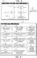
- FIG. 3is a schematic block diagram illustrating a breathing pattern analysis module of the control unit of FIG. 2 , in accordance with some applications of the present invention
- FIG. 4is a schematic block diagram illustrating additional components of a pattern analysis module of the control unit of FIG. 2 , in accordance with some applications of the present invention
- FIG. 5is a schematic illustration of a semi-rigid sensor plate that is used as a motion sensor, in accordance with some applications of the present invention
- FIGS. 6A-Bare schematic illustrations of a motion sensor coupled to a chair, in accordance with some applications of the present invention.
- FIG. 7is a schematic illustration of apparatus for identifying inefficient respiration of a subject, in accordance with some applications of the present invention.
- FIG. 8is a schematic illustration of a method for detecting ectopic heartbeats, in accordance with some applications of the present invention.
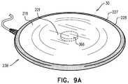
- FIGS. 9A-Bare schematic illustrations of a motion sensor comprising a sensor plate, in accordance with some applications of the present invention.
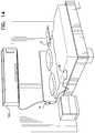
- FIGS. 10A-Dare schematic illustrations of a sensor-holding plate, in accordance with some applications of the present invention.
- FIG. 11is a schematic illustration of apparatus comprising a motion sensor, control unit, and speaker, in accordance with some applications of the present invention.
- FIG. 12is a schematic illustration of apparatus comprising a motion sensor, control unit, and alarm clock, in accordance with some applications of the present invention.
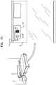
- FIG. 13is a schematic illustration of a motion sensor powered by a power supply and rechargeable battery, in accordance with some applications of the present invention.
- FIG. 14is a schematic illustration of apparatus for controlling a thermoregulation device, in accordance with some applications of the present invention.
- FIG. 15is a schematic illustration of a sensor configured to be placed within a pillow, in accordance with some applications of the present invention.
- FIG. 16is a schematic illustration of ballistocardiographic signals used for calculating an indication of a left-ventricular-ejection-time, in accordance with some applications of the present invention.
- FIG. 17is a schematic illustration of apparatus for use with a plurality of sleeping subjects, in accordance with some applications of the present invention.
- FIG. 18is a schematic illustration of apparatus for activating a medical device for a subject who is sleeping in proximity to at least one other person, in accordance with some applications of the present invention.
- FIGS. 19-20are schematic illustrations of apparatus for use with a person who is on a resting surface and for use with an illuminator, in accordance with some applications of the present invention.
- FIG. 21is a schematic illustration of apparatus for use with a waking mechanism that executes a waking routine to wake a subject who is sleeping near a second person, in accordance with some applications of the present invention
- FIG. 22is a schematic illustration of apparatus for use with a waking mechanism that executes a waking routine to wake a subject who is on a resting surface, in accordance with some applications of the present invention
- FIG. 23is a schematic illustration of apparatus for use with (i) a waking mechanism that executes a waking routine to wake a subject who is on a resting surface, and (ii) an output unit, in accordance with some applications of the present invention
- FIG. 24is a schematic illustration of apparatus for identifying a posture of a subject, in accordance with some applications of the present invention.
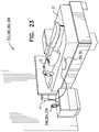
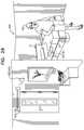
- FIG. 25is a schematic illustration of apparatus for monitoring a subject, in accordance with some applications of the present invention.
- FIG. 26is a schematic illustration of apparatus for monitoring a subject, in accordance with some applications of the present invention.
- FIG. 27Ais a schematic illustration of apparatus comprising a motion sensor, a mains-power-connection device, and a control unit, in accordance with some applications of the present invention
- FIG. 27Bis a schematic illustration of a mains-power-connection device, in accordance with some applications of the present invention.
- FIGS. 28 and 29are schematic illustrations of apparatus for use with a burglar alarm, in accordance with some applications of the present invention.
- FIG. 30is a schematic illustration of apparatus for use with a burglar alarm, in accordance with some applications of the present invention.
- FIG. 31is a schematic illustration of various apparatus for use with a subject who shares a bed with a second person, in accordance with some applications of the present invention.
- FIG. 32is a plot of a motion signal that includes a portion thereof that exhibits ringing, as analyzed in accordance with some applications of the present invention.
- FIGS. 33A-Bare schematic illustrations of respective views of a motion sensor, in accordance with some applications of the present invention.
- FIG. 1is a schematic illustration of a system 10 for monitoring a chronic medical condition of a subject 12 , in accordance with some applications of the present invention.
- System 10typically comprises a motion sensor 30 , a control unit 14 , and a user interface (U/I) 24 .
- System 10is generally similar to system 10 described in US 2011/0112442 to Meger and in US 2012/0253142 to Meger, both of which applications are incorporated herein by reference, except for differences described herein.
- user interface 24is integrated into control unit 14 , as shown in the figure, while for other applications, the user interface and the control unit are separate units.
- user interface 24includes a display.
- control unit 14is integrated into control unit 14 , in which case user interface 24 is either also integrated into control unit 14 or remote from control unit 14 .
- control unit 14 and/or user interface 24 of system 10are implemented in a mobile device (such as a cellular phone, a pager, and/or a tablet computer).
- motion sensor 30is a “non-contact sensor,” that is, a sensor that does not contact the body of subject 12 or clothes subject 12 is wearing. In other applications, motion sensor 30 does contact the body of subject 12 or clothes subject 12 is wearing. In the former applications, because motion sensor 30 does not come in contact with subject 12 , motion sensor 30 detects motion of subject 12 without discomforting or inconveniencing subject 12 . For some applications, motion sensor 30 performs sensing without the knowledge of subject 12 , and even, for some applications, without the consent of subject 12 . For some applications, motion sensor 30 does not have a direct line of sight with subject 12 or the clothes subject 12 is wearing.
- motion sensor 30is used to refer to a sensor that does not contact or view the subject or clothes the subject is wearing
- sensor 316refers more generally to any type of sensor, e.g., a sensor that includes an electromyographic sensor and/or an imaging sensor.
- a phrase such as “sensor 316 (e.g., motion sensor 30 )”should be construed to mean that the scope of the described invention includes the use of any type of sensor, but specifically, a non-contact and non-viewing sensor may be used.
- Motion sensor 30may comprise a ceramic piezoelectric sensor, vibration sensor, pressure sensor, or strain sensor, for example, a strain gauge, configured to be installed under a resting surface 37 , and to sense motion of subject 12 .
- the motion of subject 12 sensed by sensor 30may include regular breathing movement, heartbeat-related movement, and other, unrelated body movements, as discussed below, or combinations thereof.
- sensor 30comprises a standard communication interface (e.g. USB), which enables connection to standard monitoring equipment.
- control unit 14is coupled to one or more additional sensors 60 applied to subject 12 , such as a blood oxygen monitor 86 (e.g., a pulse oximeter/photoplethysmograph), an ECG monitor 62 , weight sensor 81 (e.g. a weight sensor embedded into a bed as manufactured by Stryker Inc. of Kalamazoo, Mich.), a moisture sensor 85 , an angle sensor 87 , and/or a temperature sensor 80 .
- a blood oxygen monitor 86e.g., a pulse oximeter/photoplethysmograph
- ECG monitor 62e.g., ECG monitor 62
- weight sensor 81e.g. a weight sensor embedded into a bed as manufactured by Stryker Inc. of Kalamazoo, Mich.
- moisture sensor 85e.g. a weight sensor embedded into a bed as manufactured by Stryker Inc. of Kalamazoo, Mich.
- an angle sensor 87e.g. a temperature sensor 80
- Motion sensor 30is typically coupled to a resting surface 37 upon which the subject rests.
- motion sensor 30may be placed under a mattress of a bed, and may sense motion of the subject while the subject is in the bed, and generate a motion sensor signal in response thereto.
- motion sensor 30may be coupled to a chair (e.g., a wheelchair) upon which the subject sits, and may sense motion of the subject while the subject is sitting in the chair, and generate a motion sensor signal in response thereto.
- system 10includes a first motion sensor which is under the mattress of the subject's bed, and a second motion sensor 30 , which is coupled to a chair in the subject's room.
- the first sensorsenses motion of the subject while the subject is in the bed
- the second motion sensorsenses motion of the subject while the subject is in the chair.
- System 10monitors the subject responsively to both the first and the second sensor signals, as described in US 2013/0267791 to Halperin, which is incorporated herein by reference.
- a plurality of motion sensorsare coupled to a single resting surface, and are used as motion sensor 30 .
- two or more motion sensors that are disposed under the subject's mattressmay be used as motion sensor 30 .
- only a single sensoris coupled to a given resting surface.
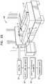
- FIG. 2is a schematic block diagram illustrating components of control unit 14 in accordance with some applications of the present invention.
- Control unit 14typically comprises a motion data acquisition module 20 and a pattern analysis module 16 .
- Pattern analysis module 16typically comprises one or more of the following modules: a breathing pattern analysis module 22 , a heartbeat pattern analysis module 23 , a cough analysis module 26 , a restlessness analysis module 28 , a blood pressure analysis module 29 , and an arousal analysis module 31 .
- pattern analysis moduleincludes additional modules and/or functionalities to those shown in FIG. 2 .
- pattern analysis module 16may include one or more of the additional modules and/or functionalities shown in FIG. 4 .
- two or more of analysis modules 20 , 22 , 23 , 26 , 28 , 29 , and 31are packaged in a single housing.
- the modulesare packaged separately (for example, so as to enable remote analysis, by one or more of the pattern analysis modules, of breathing signals acquired locally by data acquisition module 20 ).
- User interface 24typically comprises a dedicated display unit, such as an LCD or CRT monitor.
- the user interface 24comprises a wireless or wired communication port for relaying the acquired raw data and/or processed data to a remote site for further analysis, interpretation, expert review, and/or clinical follow-up.
- the datamay be transferred over a telephone line, and/or over the Internet or another wide-area network, either wirelessly or via wires.
- Breathing pattern analysis module 22is configured to extract breathing patterns from the motion data, as described hereinbelow with reference to FIG. 3
- heartbeat pattern analysis module 23is configured to extract heartbeat patterns from the motion data.
- system 10comprises another type of sensor, such as an acoustic or air-flow sensor attached or directed at the subject's face, neck, chest, and/or back, or placed under the mattress.
- FIG. 3is a schematic block diagram illustrating components of breathing pattern analysis module 22 , in accordance with some applications of the present invention.
- Breathing pattern analysis module 22analyzes changes in breathing patterns, typically during sleep.
- Breathing pattern analysis module 22typically comprises a digital signal processor (DSP) 41 , a dual port RAM (DPR) 42 , an EEPROM 44 , and an I/O port 46 .
- DSPdigital signal processor
- DPRdual port RAM
- EEPROM 44electrically erasable programmable read-only memory
- I/O port 46I/O port
- modules 23 , 26 , 28 , 29 , and 31may include a digital signal processor, a dual port RAM, an EEPROM, and an I/O port similar to digital signal processor 41 , dual port RAM 42 , EEPROM 44 , and I/O port 46 .
- Breathing pattern analysis module 22may be used (e.g., to facilitate ascertaining a sleep stage of a subject) with various apparatus and methods described herein, such as, for example, apparatus 334 , described hereinbelow with reference to FIGS. 19-20 .
- data acquisition module 20is configured to non-invasively monitor breathing and heartbeat patterns of subject 12 .
- Breathing pattern analysis module 22 and heartbeat pattern analysis module 23are configured to extract breathing patterns and heartbeat patterns respectively from the raw data generated by data acquisition module 20 , and to perform processing and classification of the breathing patterns and the heartbeat patterns, respectively.
- Breathing pattern analysis module 22 and heartbeat pattern analysis module 23are configured to analyze the respective patterns in order to (a) predict an approaching clinical episode, such as an asthma attack, heart condition-related lung fluid buildup, sepsis, cardiac arrest, or respiratory depression, and/or (b) monitor the severity and progression of a clinical episode as it occurs.
- User interface 24is configured to notify subject 12 and/or a clinician of the predicted or occurring episode.
- Prediction of an approaching clinical episodefacilitates early preventive treatment, which generally improves outcomes, e.g., by lowering required dosages of medication, and/or lowering mortality and morbidity.
- an earlier identification of subject deteriorationmay prevent the need to admit the subject to the ICU, shorten his length of stay, and increase the likelihood for successful recovery to discharge.
- Breathing pattern analysis module 22 and heartbeat pattern analysis moduletypically derive breathing patterns and heartbeat patterns from the raw data in accordance with the techniques described in US 2011/0112442 to Meger and in US 2012/0253142 to Meger, both of which applications are incorporated herein by reference.
- system 10is configured to monitor clinical parameters of the subject, and to generate alerts and/or reports in response thereto, in a generally similar manner to system 10 described US 2011/0112442 to Meger and in US 2012/0253142 to Meger, both of which applications are incorporated herein by reference.
- pattern analysis moduleincludes signal analysis functionality 90 .
- the signal analysis functionalityis configured to analyze the signals received from the sensors that provide input to control unit 14 and to determine a condition of the subject and/or generate an output (e.g., an alert), in response thereto.
- Many of the functionalities of control unit 14 that are described herein as being performed by pattern analysis module 16are performed by the signal analysis functionality of the pattern analysis module.
- Pattern analysis moduletypically further includes alert-generation-functionality 92 that is configured to generate an alert in response to the signal analysis that is performed by the signal analysis functionality.
- alertsmay be generated on pagers of clinicians, at user interface (e.g., display) 24 , and/or at a central monitoring system user interface (e.g., display).
- pattern analysis moduleincludes score calculating functionality 100 configured to calculate a score in response to the signal analysis that is performed by the signal analysis functionality.
- pattern analysis moduleincludes additional functionalities and/or modules, such as a shallow-breathing-pattern-identification functionality 101 , a subject identification module 102 , a subject-position-identification functionality 104 , an irregular-sleep-detection functionality 106 , a decreasing-cardioballistic-amplitude-detection functionality 108 , a cardiac-arrhythmia-detection functionality 110 , an inefficient respiration identification functionality 111 , a cardiac-risk-detection functionality 112 , protocol input functionality 114 , athletic-exercise-receiving functionality 116 , and/or nutrition-receiving functionality 118 .
- additional functionalities and/or modulesare described in further detail hereinbelow.
- the pattern analysis moduleincludes subject identification module 102 .
- the subject identification moduleis configured to determine which motion signals detected by motion sensor 30 were generated by the subject. For example, in cases in which the subject who is being monitored is sharing a bed with a second person (e.g., the subject's partner), the subject identification module determines which components of the motion signal detected by the motion sensor were generated by the subject and which were generated by the second person. The pattern analysis module then analyzes the components of the signal that were generated by the subject, and generates outputs (such as alerts), as described herein, in response thereto.
- the subject identification moduleis configured to determine when the subject is out of bed by determining that the motion signal detected by the motion detector is being generated by the second person.
- the subject identification moduleis configured to determine which components of the motion signal detected by the motion sensor were generated by the subject even when the subject is smaller than the second person.
- subject identification module 102is configured to determine which components of the motion signal detected by motion sensor 30 were generated by the subject using one or more of the following techniques:
- the subject identification moduleidentifies patterns (e.g., a respiratory pattern, a heart rate pattern, and/or a motion pattern, e.g., a large body-movement pattern) that are characteristic of, respectively, the subject and the second person.
- the subject identification moduledetermines that components of the signal that correspond to the characteristic patterns of the subject have been generated by the subject.
- the subject identification modulelearns characteristic patterns of the subject by utilizing a weight sensor (e.g., as described hereinbelow), and/or or utilizing long term average patterns of the subject.
- the pattern identification moduleoperates in a learning mode, in which the module learns characteristic patterns of the subject.
- the subject identification moduleidentifies characteristic signal strengths generated, respectively, by the subject and by the second person.
- the sensormay be disposed underneath the subject who lies on a first side of the bed and the second person may typically lie on the second side of the bed.
- signals generated by the subjectare typically characterized as being of greater strength than those generated by the second person.
- the subjectmay be smaller than the second person, and may therefore generate signals that are characterized as being weaker than signals generated by the second person.
- motion sensor 30is configured to facilitate determination by subject identification module 102 of which components of the motion signal were generated by the subject.
- the sensormay be placed in a position, and/or shaped, such as to strengthen the signal that is received from the subject.
- the sensoris placed underneath the subject's mattress at a position higher than where the subject rests his/her head, such that the strongest signals that the sensor receives are those generated by the longitudinal cardio-ballistic effect of the subject.
- the motion sensorcomprises at least a portion of an L-shaped structure, as shown in FIGS. 33A-B .
- the structureis shaped to define horizontal and vertical portions that form approximately (or precisely) a right angle with one another.
- the horizontal portion of the structureis placed underneath the subject's mattress, and the vertical portion of the structure is placed adjacent to and in contact with a side of the subject's mattress (e.g., the head of the subject's mattress).
- the horizontal portion of the structuredoes not perform any sensing functionalities but acts as a support element 49 for supporting the vertical portion adjacent to and in contact with a side of the subject's mattress (e.g., the head of the subject's mattress), the vertical portion acting as sensor 30 .
- a different support elementis used to support sensor 30 at a position adjacent to and in contact with a side of the subject's mattress (e.g., the head of the subject's mattress).
- a compressible membersuch as a cushion
- a surfacee.g., a wall or a headboard
- the sensoris disposed on a stretchable band (e.g., an elastic band).
- the bandis stretched in order to facilitate placement of the band around the sides of the subject's mattress, and the band then shrinks, such as to maintain the sensor adjacent to and in contact with a side of the subject's mattress (e.g., the head of the subject's mattress).
- the sensoris not disposed on a stretchable band, but the sensor is maintained adjacent to and in contact with a side of the subject's mattress (e.g., the head of the subject's mattress), using a stretchable band.
- the motion sensorincludes a weight sensor that is configured to measure a weight that is placed on top of the weight sensor, and to identify that the subject is lying above the motion sensor in response thereto.
- the subject identification moduleidentifies signals from the motion sensor as having been generated by the subject, in response to the signal generated by the weight sensor.
- the weight sensoris used to determine when the subject is directly on top of the weight sensor.
- the pattern identification moduleoperates in a learning mode, in which the module learns characteristic patterns of the subject, as described hereinabove.
- respective first and second motion sensorsare placed underneath the subject and the second person who uses the bed.
- Subject identification module 102determines which components of the motion signal were generated by the subject in response to the signals from both the first and the second motion sensors.
- FIG. 7is a schematic illustration of apparatus for identifying inefficient respiration of a subject 234 , in accordance with some applications of the present invention.
- Inefficient respirationmay be indicative of a clinical episode related to a respiratory disorder such as obstructive apnea or asthma.
- Inefficient respirationcorresponds to a situation in which the respiration movements are large relative to the volume of respiration flow. This phenomenon may occur in one of the two following ways:
- respiration flowis normal, but respiration movements are abnormally large, such as where the subject needs to use upper-body muscles that are normally not used for respiration.
- pattern analysis module 16 of control unit 14comprises inefficient respiration identification functionality 111 , as described hereinabove with respect to FIG. 4 .
- the identification of inefficient respirationtypically proceeds according to the following steps:
- a respiration-related motion signalis identified in the mechanical sensor signal that is detected by sensor 30 .
- the amplitude of this signalcorresponds to the respiration movements of the subject.
- respiration flow meter 236may be handled by the subject, or alternatively, by a caregiver, e.g., a physician or nurse.
- the inefficient respiration identification functionalitycalculates a relationship of the amplitude of the respiration-related motion signal to the volume of respiration flow, and inefficient respiration is identified in response to this relationship.
- the relationshipmay comprise the quotient of the quantities, e.g., Amplitude of Signal/Volume of Flow.
- the quotientis compared to a baseline value, and inefficient respiration is identified in response to this comparison.
- inefficient respirationmay be identified if the quotient of Amplitude/Volume is increased by a factor of at least 1.5 relative to the baseline value (e.g., the factor may be 2).
- Identifying the inefficient respiration in response to a relationship between the quantities, rather than based on the absolute values of the quantities,helps facilitate the identification of inefficient respiration even if one of the quantities is normal, as described hereinabove.
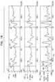
- FIG. 8is a schematic illustration of a method for detecting ectopic heartbeats, e.g., premature ventricular contractions, in accordance with some applications of the present invention.
- heartbeat pattern analysis module 23( FIG. 2 ) is configured to detect ectopic beats of a subject.
- the cardiac signal component of the sensor signal generated by sensor 30is filtered into a high-frequency component 206 and a low-frequency component 204 .
- Components 204 and 206are shown plotted in arbitrary units in FIG. 8 .
- both normal and ectopic beatsexhibit high-frequency characteristics indicative of ventricular contraction, the high frequency component indicates both normal and ectopic beats.
- ectopic beatslack some low-frequency characteristics indicative of blood flow; consequently, the low frequency component generally indicates normal (but not ectopic) beats.
- Portions 200 of the high-frequency component, corresponding to ventricular contractions of the subject,are identified by heartbeat pattern analysis module 23 ; a pair of such portions typically indicates a single heartbeat. For each pair of portions 200 , a corresponding portion of the low-frequency component is analyzed. If this corresponding portion is indicative of blood flow, e.g., as shown in portions 202 (solid line), the heartbeat is determined to be a normal beat.
- the heartbeatis determined to be an ectopic beat.
- a pair 201 of portions 200corresponds to a portion 202 indicative of blood flow
- a pair 210 of portions 200corresponds to a portion 208 which is not indicative of blood flow.
- the time between the two elements of a pair of portions 200is used to diagnose cardiac conditions such as early heartbeats, missing heartbeats, and low stroke volume.
- the lower cutoff frequency for the low-frequency band-pass filtermay be, for example, at least 1.5 and/or less than 4 Hz (e.g., 2 Hz), while the higher cutoff frequency may be, for example, at least 4.1 and/or less than 7.5 Hz (e.g., 5 Hz).
- the lower cutoff frequency for the high-frequency band-pass filtermay be, for example, at least 6.5 and/or less than 11.5 Hz (e.g., 9 Hz), while the higher cutoff frequency may be, for example, at least 11.6 and/or less than 16.5 Hz (e.g., 14 Hz).
- the lower cutoff frequency for the low-frequency band-pass filtermay be, for example, at least 2.5 and/or less than 3.5 Hz, while the higher cutoff frequency may be, for example, at least 4.5 and/or less than 5.5 Hz.
- the lower cutoff frequency for the high-frequency band-pass filtermay be, for example, at least 8.5 and/or less than 9.5 Hz, while the higher cutoff frequency may be, for example, at least 13.5 and/or less than 14.5 Hz.
- FIG. 5is a schematic illustration of a semi-rigid sensor plate 140 that is used as motion sensor 30 , in accordance with some applications of the present invention.
- the sensoris designed and/or placed under the subject's bed such as to detect only motion of the subject who is lying on the side closer to the sensor.
- the sensor mechanical propertiesare designed to collect the vibration mechanical signal only locally from the subject lying directly on top or very close to the sensor. This allows mechanical filtering of signals coming from the partner, and detection of only the signal of the subject on top of the sensor.
- edges 142 of the sensor plateare hardened with respect to a central portion 144 of the sensor plate.
- the sensor hardening on the circumferenceis achieved by mechanically preventing a 2-5 mm rim of the semi-rigid sensing plate from vibrating. This typically substantially reduces the signal generated by the second person as compared to that generated by the subject.
- FIGS. 9A-Bare schematic illustrations of motion sensor 30 comprising a sensor plate 238 , in accordance with some applications of the present invention.
- Sensor plate 238is typically for use with a subject who shares a bed with a second person, e.g., as shown in FIG. 21 .
- sensor plate 238comprises an edge region 227 that is more rigid than a central portion 221 of the sensor plate, such as to reduce movement of the plate in response to motion of the second person, relative to if edge region 227 of the sensor plate were not more rigid than central portion 221 .
- edge region 227may take the form of a rigid noise filter rim 228 , and/or a rigid sensor-holding-plate rim 220 .
- Motion sensor 30is configured to be placed on the bed such that when the subject and the second person are on the bed (e.g., as in FIG. 21 ), sensor plate 238 is disposed underneath the subject and not disposed underneath the second person.
- a sensor element 366e.g., a piezoelectric sensor element
- motion sensor 30detects motion of the subject, by sensor-holding plate 218 moving in response to motion of the subject.
- the motion signal generated by motion sensor 30is then analyzed by control unit 14 , as described throughout the present application.
- the relative rigidity of edge region 227generally reduces the extent to which motion of the second person is detected by motion sensor 30 , relative to motion of the subject. (In the present description, the word “sensor” may sometimes be used to refer to sensor element 366 .)
- a thickness of the edge region(e.g., thickness t described hereinbelow), measured between an inner perimeter of the edge region and an outer perimeter of the edge region, is at least 2 mm and/or less than 20 mm, e.g., less than 8 mm.
- sensor plate 238comprises sensor-holding plate 218 and a noise filter plate 226 that is distinct from sensor-holding plate 218 .
- noise filter plate 226is typically shaped to define a noise filter rim 228 .
- Noise filter rim 228is more rigid than central portion 221 of the sensor-holding plate, such as to reduce movement of the sensor-holding plate in response to motion of the second person, relative to if the noise filter rim were not more rigid than the central portion of the sensor-holding plate.
- noise filter rim 228allows for mechanical filtering of signals coming from the partner, in a manner generally described hereinabove with respect to edges 142 of sensor plate 140 ( FIG. 5 ).
- sensor-holding plate 218may be shaped to define a rigid sensor-holding-plate rim 220 (which is more rigid than central portion 221 ), the function of which is generally similar to that of noise filter rim 228 .
- a thickness t 2 of the sensor-holding-plate rimmeasured between an inner perimeter of the sensor-holding-plate rim and an outer perimeter of the sensor-holding-plate rim, is at least 2 mm and/or less than 8 mm, or alternatively, at least 8 mm and/or less than 20 mm.
- the top of noise filter rim 228is generally level with the top of sensor-holding plate 218 , while in other applications, the top of noise filter rim 228 is higher, e.g., it is greater than 1 and/or less than 5 mm higher. In some applications, a thickness t of noise filter rim 228 , measured between an inner perimeter of the noise filter rim and an outer perimeter of the noise filter rim, is at least 2 mm and/or less than 8 mm, e.g., 5 mm.
- sensor-holding plate 218is shaped to hold sensor element 366 , e.g., via a sensor receptacle 222 , thus allowing for the sensor element to be coupled to the sensor plate.
- the sensor-holding platefurther comprises an electronics receptacle 224 , configured to hold electronic circuitry which may include, for example, an amplifier, analog to digital converter, and/or a communication element.
- the sensor-holding platedoes not comprise electronics receptacle 224 , and the circuitry is disposed outside of the sensor-holding plate.
- sensor-holding plate 218is reversibly couplable to noise filter plate 226 .
- the couplingmay be effected, for example, by means of sensor-holding-plate rim 220 , which is disposed along the perimeter of sensor-holding plate 218 and is configured to fit into a groove 230 disposed along the inside perimeter of noise filter plate 226 .
- a width of groove 230measured in a direction from an outer perimeter of the groove toward an inner perimeter of the groove, is greater than 0.05 and/or less than 2 mm greater than thickness t 2 of rim 220 .
- FIGS. 10A-Dare schematic illustrations of sensor-holding plate 218 , in accordance with some applications of the present invention.
- FIG. 10Ashows sensor-holding plate 218 with a continuous rim 220 which appears generally as shown in FIG. 9B .
- FIG. 10Bshows sensor-holding plate 218 with a discontinuous rim 225 , shaped to define a plurality of slots (i.e., openings, or gaps) 223 therein, disposed around rim 225 .
- Slots 223create a “defocusing” effect, i.e., they facilitate the sensing of motion from areas which are not directly above sensor-holding plate 218 .
- sensor-holding plate 218can be configured for different beds sizes.
- FIG. 10Cshows sensor-holding plate 218 with a discontinuous rim 211 , shaped to define one or more anisotropically-arranged slots 219 therein.
- Proper orientation of slots 219may facilitate the sensing of motion originating from one or more particular areas not directly above sensor-holding plate 218 .
- the sensor-holding plate of FIG. 10Cmay be placed at the head of the bed, oriented such that slot 219 is directed toward the legs of the subject. In this manner, rim 211 will generally prevent the partner's motion from being sensed, while generally allowing the subject's motion to be sensed.
- FIGS. 10B-Cshow the sensor-holding-plate rim shaped to define slots therein, the scope of the present invention includes rims which comprise thinned portions which function in a manner generally similar to slots 223 and 219 .
- the rim 229 of sensor-holding plate 218may comprise one or more detachable parts 209 .
- the detachment of parts 209results in the opening of slots such as slots 223 and slots 219 .
- Detachable parts 209allow for reducing the manufacturing cost of sensor-holding plate 218 , since the desired slots can generally be opened post-manufacture. For example, if the subject is sleeping alone and the bed is relatively large, the subject may decide to detach a plurality of small detachable parts 209 to create slots 223 , as shown in FIG. 10B , such that motion of the subject is detected even when the subject is not directly over sensor-holding plate 218 . In some applications, parts 209 which have been detached may subsequently be re-attached.
- sensor-holding plate 218may need to be fixed in place, such that its orientation remains generally constant.
- sensor-holding plate FIG. 10Cis to be placed under the head of the bed with a slot 219 directed towards the subject's legs
- sensor-holding plate 218may be fixed in place within the subject's pillow, which in general tends to be perpendicular to the subject's longitudinal axis.
- FIGS. 10A-Dmay be practiced in combination with the applications shown in FIGS. 9A-B .
- the various rims that are shown in FIGS. 10A-Dmay be more rigid than central portion 221 , as described hereinabove.
- sensor-holding plate 218is circular; a sensor-holding plate shaped in this manner has been found by the inventors to be generally effective in transmitting mechanical forces to the sensor coupled to the center thereof.
- the sensor element coupled to sensor-holding plate 218e.g., via sensor receptacle 222 , is also circular. It has been found by the inventors that the ratio of sensor element diameter (which is generally similar to diameter D 0 of sensor receptacle 222 shown in FIG. 9B ) to sensor-holding plate diameter D 1 is a relevant factor for effective transmission of mechanical forces to the sensor.
- the ratio of sensor element diameter to sensor-holding plate diameter D 1is greater than 0.1 and/or less than 0.6.
- sensor-holding plate 218is not circular, e.g., it may be square or another shape.
- noise filter plate 226is shaped accordingly, such that the noise filter is configured to be reversibly couplable to the sensor-holding plate as generally described with respect to FIGS. 9A-B , mutatis mutandis.
- sensor plate 238is used in combination with subject identification module 102 , described hereinabove with respect to FIG. 4 . Although sensor plate 238 reduces the degree to which motion sensor 30 detects motion of the second person, it is possible that the sensor will nonetheless detect some of this motion. Subject identification module 102 therefore identifies components of the motion signal from sensor 30 that were generated by the subject, by distinguishing between components of the motion signal that were generated respectively by the subject and by the second person, e.g., as described hereinabove. In other applications, subject identification module 102 is used without sensor plate 238 .
- FIG. 31is a schematic illustration of various apparatus 500 a - e for use with a subject 12 who shares a bed with a second person 502 , in accordance with some applications of the present invention.
- motion sensor 30detects motion of subject 12 and motion of second person 502 , and generates a motion signal 504 in response thereto.
- Motion sensor 30is typically a single motion sensor that does not contact or view the subject, clothes the subject is wearing, the second person, or clothes the second person is wearing.
- control unit 14e.g., via subject identification module 102 ( FIG.
- apparatus 500 a - ediffer from each other in the technique(s) used to perform the distinguishing/subject-identification, in the analysis that is performed pursuant to the distinguishing/subject-identification, and/or in the output that is generated.
- control unit 14is configured to identify that a portion of the motion signal was generated in response to motion of the second person, and not in response to motion of the subject, by identifying that the portion exhibits ringing.
- FIG. 32is a plot of motion signal 504 that includes a portion 506 thereof that exhibits ringing, as analyzed in accordance with some applications of the present invention.
- Motion signal 504includes portions 501 a and 501 b that, respectively, precede and follow portion 506 .
- Portions 501 a and 501 bexhibit a generally regular, cyclical pattern that is typically indicative of the cardiac and respiratory motion of the subject.
- Portion 506has more of a step-response profile, which is typically indicative of large body-movement.
- the ringing in portion 506indicates that the source of the large body-movement is the second person, who is not directly above the sensor.
- control unit 14ascertains that portion 506 includes a set of at least three consecutive extrema 508 (i.e., three consecutive maxima, or three consecutive minima), each of which (following the first extremum of the set) is separated from the preceding extremum of the set by a time T 0 that falls within a given time range (e.g., 0.15-0.45 seconds).
- a given time rangee.g., 0.15-0.45 seconds
- control unit 14further ascertains that respective differences between (i) magnitudes of consecutive extrema 508 , and (ii) a magnitude of an extremum 510 that precedes the set of consecutive extrema (typically an initial “spike” that precedes the set), fall within a given amplitude range. For example, the control unit may identify that the respective differences are between 10%-150% of the magnitude of extremum 510 . Typically, the control unit further ascertains that a difference between (i) a smallest magnitude 512 of the consecutive extrema, and (ii) a largest magnitude 514 of the consecutive extrema, is less than a threshold (e.g., 30% of smallest magnitude 512 ).
- a thresholde.g. 30% of smallest magnitude 512
- FIG. 32shows the ringing phenomenon only for large body-movement, ringing may also be exhibited in portions of signal 504 that reflect other types of motion, such as respiratory motion or cardiac motion.
- Apparatus 500 ais configured to identify the second person as the source of these other types of motion, by performing the ringing-identification techniques described hereinabove.
- Apparatus 500 buses a different technique to identify that a given portion of the motion signal was generated in response to large body-movement of the second person, and not in response to motion of the subject.
- control unit 14is configured to “learn” an amplitude threshold Th by analyzing a portion of the motion signal (e.g., portion 501 a ) that was generated in response to motion (e.g., cardiac and/or respiratory motion) of the subject, and calculating threshold Th based on the analysis.
- a portion of the motion signale.g., portion 501 a
- motione.g., cardiac and/or respiratory motion
- Thmay be a multiple of amplitude A 4 of portion 501 a .
- the control unitidentifies that the given portion of the motion signal was generated in response to large body-movement of the second person, and not in response to motion of the subject. For example, in FIG. 32 , extremum 510 is less than Th, such that portion 506 is determined to have been generated by large body-movement of the second person.
- Apparatus 500 cuses yet another technique for distinguishing between motion of the subject and motion of the second person.
- control unit 14identifies a subject-motion component of the motion signal that was generated in response to motion of the subject, e.g., portions 501 a and 501 b of FIG. 32 .
- a given portione.g., portion 506
- control unit 14compares the amplitude A 3 of the subject-motion component following the given portion, relative to the amplitude A 4 before the given portion.
- FIG. 32shows A 4 being different from A 3 , but not by more than the threshold amount, such that portion 506 is determined to have been generated by motion of the second person.
- control unitis typically configured to use any of the techniques described hereinabove, separately or in combination.
- Apparatus 500 dalso comprises motion sensor 30 and control unit 14 , and also distinguishes between motion of the subject and motion of the second person, e.g., using some or all of the techniques of apparatus 500 a - c .
- control unit 14is configured to, by analyzing the signal from motion sensor 30 in an analysis step 518 , identify an effect of large body-movement of the second person on sleep of the subject, and in response thereto, generate a sleep-disturbance output 516 .
- Output 516may include a report (e.g., a digital, and/or printed, and/or audio report), which may include alphanumeric and/or graphical content.
- output 516may include a recommendation to change a parameter, and/or instructions to a device to change a parameter.
- output 516facilitates the reduction of the extent to which movement by second person 502 disturbs the sleep of subject 12 .
- output 516includes an assessment of an effectiveness of a parameter at reducing the effect of the large body-movement of the second person on the sleep of the subject.
- the control unitmay assess one or more parameters 520 such as:
- a parametere.g., a firmness, or a width
- a parametere.g., a firmness, or a width
- a sleeping arrangement ofe.g., a distance between) the subject and the second person, and/or
- a room-environment parametere.g., a level of light or sound, or a temperature, in the room.
- parameter types (a)-(d)e.g., a level of light in the room
- other parameter typese.g., a firmness of mattress 522
- the control unitanalyzes motion signal 504 in light of the parameter(s), and generates the assessment in response to the analysis. For example, the control unit may compare data from several nights of sleep, and/or compare the data from the given pair of sleepers with data from other pairs of sleepers, to ascertain how the parameter(s) affect the level of sleep disturbance.
- Output 516may include, for example, an assessment message such as “A temperature between 23-25 C in the room is more effective at reducing sleep disturbance, relative to other temperatures.”
- output 516may include a recommendation to reduce the effect of the large body-movement of the second person on the sleep of the subject, by adjusting an adjustable parameter such as any of parameters (a)-(d) listed above.
- output 516may include a recommendation message such as “To reduce sleep disturbance, you may wish to reduce the tilt angle of your bed.”
- apparatus 500 dis used (e.g., by a mattress provider or consumer) to compare between different types of mattresses.
- output 516may include a comparison between (a) the effectiveness of a parameter of one given type of mattress, and (b) the effectiveness of the parameter of a different type of mattress.
- output 516may show a consumer that a firmer mattress is more effective than a less-firm mattress at reducing sleep disturbance, and based on this comparison, the consumer may decide to purchase the firmer mattress.
- output 516includes instructions to a device 524 to adjust an adjustable parameter, e.g., any of (a)-(d) listed above.
- FIG. 31shows output 516 including instructions to a controller 526 to adjust a tilt angle of bed 37 .
- Apparatus 500 ealso comprises motion sensor 30 and control unit 14 , and also distinguishes between motion of the subject and motion of the second person, e.g., using some or all of the techniques of apparatus 500 a - c .
- motion sensor 30comprises a mechanical-filtering element, such as noise filter rim 228 (described hereinabove with reference to FIGS. 9A-B ), which is configured to reduce a response of the motion sensor to motion of the second person, relative to motion of the subject.
- Control unit 14analyzes motion signal 504 , assesses an effectiveness of the mechanical-filtering element at reducing the response of the motion sensor to motion of the second person, and generates an output in response thereto.
- control unit 14may make an assessment that the mechanical-filtering element is relatively ineffective.
- output 516may include, for example, a recommendation to replace the current noise filter rim with a thicker noise filter rim.
- apparatus 500 d and apparatus 500 ethere is a “philosophical” difference between apparatus 500 d and apparatus 500 e , in that a typical objective in using apparatus 500 e is to improve the filtering out of motion from the second person (perhaps to the point of near-complete filtering), whereas apparatus 500 d requires that sensor 30 detect at least some of the motion from the second person. Nevertheless, apparatus 500 d and 500 e may be combined, such that a single control unit 14 is configured to perform both the functions of apparatus 500 d and the functions of apparatus 500 e.
- FIG. 15is a schematic illustration of a sensor 30 configured to be placed within a pillow 301 , in accordance with some applications of the present invention.
- motion sensor 30is configured to be placed within pillow 301 of subject 12 .
- FIG. 11is a schematic illustration of apparatus comprising a motion sensor 30 , control unit 14 , and speaker 232 , in accordance with some applications of the present invention.
- motion sensor 30 and a speaker 232are configured to be placed under the head of a subject who shares a bed with another person. (Thus, FIG. 11 depicts resting surface 37 as a double bed.)
- sensor 30may be placed within the pillow of the subject.
- Speaker 232is configured to play music responsively to output from control unit 14 , for example, in order to help the subject fall asleep or use biofeedback techniques to relax.
- sensor plate 238described hereinabove with respect to FIGS. 9A-B , is used.
- control unit 14may eliminate artifacts generated by speaker 232 by subtracting the signal generated by the speaker from the motion signal.
- the signal generated by speaker 232may be received, for example, from the speaker controlling circuit or from another sensor on the speaker.
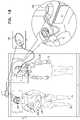
- FIG. 14is a schematic illustration of apparatus for controlling a thermoregulation device 240 , in accordance with some applications of the present invention.
- control unit 14is connected to a thermoregulation device 240 located, for example, in the subject's bed or elsewhere in the subject's bedroom.
- Control unit 14monitors the subject's sleep stages and controls thermoregulation device 240 accordingly.
- thermoregulation deviceswhich may be configured to be controlled by control unit 14 include air-conditioning units, electric heaters, radiators, bed coolers, and electric blankets.
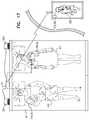
- FIG. 12is a schematic illustration of apparatus comprising a motion sensor 30 , control unit 14 , and alarm clock 212 , in accordance with some applications of the present invention.
- an alarm clock 212is configured to receive an output from control unit 14 . The output is generated in response to a signal from motion sensor 30 , and indicates whether a resting surface 37 , e.g., a bed, is occupied by a subject. In response to the output indicating that resting surface 37 is unoccupied, alarm clock 212 inhibits itself from sounding. This reduces the likelihood of an alarm waking other members of the household, in cases where the subject arose from resting surface 37 without taking measures to ensure that the alarm would not subsequently begin or continue to sound.
- alarm clock 212 and control unit 14are integrated into a common unit 213 . In other applications, alarm clock 212 is separate from control unit 14 , and communicates therewith by wired or wireless communication means.
- alarm clock 212is configured to sound after a delay, in response to the output from control unit 14 indicating that the bed is occupied following a previous sounding of the alarm clock.
- FIG. 13is a schematic illustration of a motion sensor 30 powered by an external power supply 216 (i.e., a power supply that is external to the motion sensor), and a rechargeable battery 214 , in accordance with some applications of the present invention.
- motion sensor 30may be powered by an external power supply 216 , which draws current via a power cord 217 connected to a wall outlet. Since some subjects are uncomfortable with power being drawn from the wall and conveyed to a device which is underneath them, motion sensor 30 is configured to not draw power from power supply 216 , in response to output from control unit 14 indicating that resting surface 37 is occupied by the subject.
- sensor 30is configured to draw power from a rechargeable battery 214 , in response to the output indicating that resting surface 37 is occupied.
- Rechargeable battery 214is configured to draw power from a power supply, e.g., power supply 216 , in response to the output from the control unit indicating that the resting surface is unoccupied, and to not draw power from the power supply, in response to the output indicating that the resting surface is occupied.
- system 10is configured to analyze sleep patterns of a subject and, in response thereto, produce a sleep report which can be used, for example, for clinical sleep-study purposes.
- system 10is configured to monitor subjects who are generally healthy, in order to help the subjects maintain or improve their state of well-being.
- system 10may be configured to help a healthy subject avoid unhealthful conditions or improve sleep quality.
- system 10is configured to be used in combination with home-based appliances.
- system 10may be configured to transmit a signal to a coffee-maker, the signal indicating that the subject has woken up and/or has left the bed and might soon wish to drink a cup of coffee.
- a resting surfacee.g., a mattress
- a mattressis configured to be used with motion sensor 30 , such that motion sensor 30 may be disposed within the mattress.
- the mattressmay have an opening at its side configured to receive motion sensor 30 , as well as a receptacle contained within the mattress configured to hold the sensor. Configuring a mattress in this manner allows for the sensor to be disposed closer to the subject, relative to applications in which the sensor is disposed underneath the mattress.
- control unit 14is configured to receive mattress-related parameters such as thickness and resilience, and to analyze the signal from motion sensor 30 in light of the parameters.
- the mattress-related parametersmay facilitate the quantification of signal amplitude on more of an absolute scale, thus facilitating a more effective response to the signal. For example, if the signal from sensor 30 indicates a weak heartbeat, but the mattress is relatively thick and resilient, control unit 14 may withhold the output unit from generating an alert.
- control unit 14(e.g., via heartbeat pattern analysis module 23 ) is further configured to calculate an indication of a left-ventricle-ejection-time (LVET) of subject 12 .
- LVETis the time from the opening of the aortic valve during a heartbeat to the closing of the aortic valve during the heartbeat.
- a decrease in LVETmay be indicative of a clinical condition, such as hypovolemia and/or hemorrhaging, that requires immediate medical attention.
- FIG. 1left-ventricle-ejection-time
- Signal 300is a heartbeat-related signal that is extracted by heartbeat pattern analysis module 23 from the raw motion signal generated by sensor 30 .
- Signal 300is typically extracted by means of spectral filtering in the range of about 0.8 to about 5.0 Hz, as described hereinabove. (A matched filter may be used to extract signal 302 .)
- Signal 300is typically smoothed by a low-pass filter to yield signal 302 . (In FIG.
- signal 300is generally smooth, such that signal 302 appears substantially identical to signal 300 .
- the derivative of signal 302is calculated by module 23 , after which the derivative is typically smoothed with a low-pass filter, yielding signal 304 .
- Each of signals 300 , 302 , and 304is marked in FIG. 16 to show an indication of aortic valve openings (AO) and closings (AC). As described above, the time between these events is the LVET of the subject.
- Heartbeat pattern analysis module 23is configured to calculate an indication of the LVET by analyzing signal 304 . (In some applications, the unsmoothed derivative of signal 302 , instead of signal 304 , is analyzed.) For example, heartbeat pattern analysis module 23 may be configured to identify the most prominent positive peaks 308 in signal 304 . Following the identification of peaks 308 , module 23 identifies the positive peaks 306 that immediately precede peaks 308 , which correspond to AO, and the negative peaks 310 that immediately follow peaks 308 , which correspond to AC.
- control unit 14drives an output device, e.g., user interface (U/I) 24 , to generate an output, such as an audio and/or visual output, in response to the calculated indication.
- U/Iuser interface
- calculating the indicationinvolves averaging one or more parameters, such as the time between peaks 306 and 310 , over several heartbeats.
- control unit 14(e.g., via module 23 ) is further configured to identify a risk of hypovolemia of the subject, in response to the calculated indication of the LVET. For example, module 23 may determine that the LVET has decreased, relative to previously-calculated LVETs and/or to a subject-baseline LVET or a population-baseline LVET, such that the subject is at risk of hypovolemia. For example, the subject may be experiencing hypovolemia and/or hemorrhaging. Control unit 14 drives U/I 24 to generate the output in response to the identified risk of hypovolemia. Typically, the generated output includes an alert to a physician or other caregiver.
- control unit 14(e.g., via module 23 ) is further configured to identify a change in stroke volume of subject 12 . Typically, this is done by using the amplitude 312 of heartbeat signal 302 as an indication of the subject's stroke volume, as amplitude 312 is typically positively correlated to stroke volume.
- raw signal 300is also being processed by system 10 to identify any posture changes of the subject. For example, the system may identify a posture change using techniques as described in US 2011/0112442 to Meger, which is incorporated herein by reference.
- Control unit 14drives the output device (e.g., U/I 24 ) to generate an output, in response to the identified change in stroke volume.
- the output devicee.g., U/I 24
- control unitis further configured to identify a risk of hypovolemia of the subject, in response to the identified change in stroke volume.
- the control unitmay identify a risk of hypovolemia (e.g., of hemorrhaging), in response to the stroke volume dropping below a specified absolute or percentage threshold.
- Control unit 14drives U/I 24 to generate the output in response to the identified risk of hypovolemia.
- the generated outputwill include an alert to a physician or other caregiver.
- the risk of hypovolemiais identified in response to both the change in stroke volume and a change in LVET. For example, a slight decrease in stroke volume may be cause for alarm only if it is accompanied by a decrease in LVET.
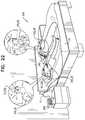
- FIG. 17is a schematic illustration of apparatus for use with a plurality of sleeping subjects 314 , in accordance with some applications of the present invention.
- the apparatuscomprises at least one sensor 316 (e.g., at least two sensors 316 , e.g., exactly two sensors 316 ) configured to monitor each of subjects 314 while the subjects sleep.
- sensors 316may comprise non-contact motion sensors 30 , configured to sense motion of the subjects while the subjects sleep.
- each sensor 30is placed underneath the outer shoulder of the subject being sensed.
- sensors 316may comprise at least one sensor of another type, such as an electromyographic sensor and/or an imaging sensor. In response to the monitoring, sensors 316 generate a respective signal for each of the subjects.
- Control unit 14is configured to analyze the signals, and, based on the analyzing, identify at least one sleep-related parameter for each of the subjects. For example, for each of the subjects, the control unit may be configured to identify one or more of the following parameters:
- a length of time for which the subject has been sleepinge.g., a length of time for which the subject has been in a deep sleep
- a number of prior awakenings of the subjecte.g., a number of prior awakenings during the present sleeping period and/or during a previous sleeping period;
- the control unitmay use one or more of the techniques described in (a) US 2007/0118054 to Pinhas (now abandoned), (b) Shinar et al., Computers in Cardiology 2001; Vol. 28: 593-596, and (c) Shinar Z et al., “Identification of arousals using heart rate beat-to-beat variability,” Sleep 21(3 Suppl):294 (1998), each of which is incorporated herein by reference.
- control unit 14At least in response to the identified sleep-related parameters, and typically further in response to receiving an input from a second sensor 318 , control unit 14 identifies at least one of the subjects for wakening, and at least one of the subjects not for wakening.
- the apparatusfurther comprises a wakening device 324 , and the control unit is configured to drive wakening device 324 to wake the subject(s) identified for wakening.
- Second sensor 318comprises, for example, an audio sensor 322 , configured to communicate (e.g., wirelessly) a signal to control unit 14 in response to sounds made by baby 320 .
- sensor 318may comprise a different type of sensor, such as non-contact motion sensor 30 and/or an image sensor.
- the control unitIn response to receiving the input from sensor 318 , the control unit identifies that baby 320 is crying, such that one of parents 314 should be wakened. Based on the sleep-related parameters, the control unit identifies the parent to be wakened.
- wakening device 324comprises a separate unit (e.g., a separate alarm-generating mechanism) for each of the sleeping subjects, such that one subject can be woken with minimal disturbance to the other.
- wakening device 324comprises a single unit.
- wakening device 324may be integrated with U/I 24 ( FIG. 2 ).
- FIG. 17shows two sensors 316
- the scope of the present inventionincludes the use of exactly one sensor 316 (e.g., exactly one motion sensor 30 ) to monitor both subjects 314 .
- the apparatus described with reference to FIG. 17may be used in combination with subject identification module 102 ( FIG. 4 ), which helps differentiate between the motion of the first subject and the motion of the second subject, and/or in combination with one or more of the mechanical filtering applications described hereinabove.
- sensor plate 140 with hardened edges 142FIG. 5
- sensor plate 238 with rigid edge region 227FIG. 9A
- other “two-person” applications described hereinbelow with reference to FIGS. 18, 20, 21, and 22may be practiced in combination with subject identification module 102 and/or one or more of the mechanical filtering applications described herein.
- Sensor 318senses a physiological parameter of a patient, and communicates the parameter to the control unit.
- sensor 318typically comprises a “dedicated” physiological sensor, such as an electrocardiograph, blood pressure monitor, etc., although sensor 318 may also comprise a sensor of the type described above, e.g., non-contact motion sensor 30 .
- the control unitdetermines that at least one, but not all, of the doctors should be woken, in order to tend to the patient.
- the control unitBased on the sleep-related parameters, as described above with respect to the parents of baby 320 , the control unit identifies at least one of the doctors for wakening, and at least one of the doctors not for wakening. (In this situation, subjects 314 will typically be sleeping on multiple respective beds, and the apparatus may comprise more than one control unit, e.g., one control unit per bed, in communication with each other.)
- control unitis further configured to generate a report that shows a history of the at least one sleep-related parameter for each of the subjects.
- the reportmay be generated at regular intervals, such as after every night. The generation of such a report may be helpful in avoiding conflicts. For example, in the parenting situation described above, the parent who was woken may feel less resentful if the report shows that despite been woken to tend to the crying baby, he/she slept better and/or longer overall, relative to the other parent.
- FIG. 18is a schematic illustration of apparatus for activating a medical device 326 (e.g., a continuous positive airway pressure (CPAP) device) for a subject 12 who is sleeping in proximity to at least one other person 328 , in accordance with some applications of the present invention.
- the apparatuscomprises at least one sensor 316 (e.g., at least two sensors 316 , e.g., exactly two sensors 316 ) configured to monitor subject 12 and person 328 .
- sensors 316may comprise non-contact motion sensors 30 , configured to sense motion of subject 12 and person 328 while they sleep.
- sensors 316may comprise at least one sensor of another type, such as an electromyographic sensor and/or an imaging sensor. In response to the monitoring, sensors 316 generate a respective signal for each of subject 12 and person 328 .
- Control unit 14analyzes the signal for the subject, and, based on the analyzing, identifies at least one physiological parameter of the subject that relates to whether or not the device should be activated. For example, the control unit may identify a respiration-related parameter of subject 12 that is indicative of an occurring or expected episode of apnea, e.g., as described in US 2013/0281866 to Shinar, which is incorporated herein by reference. Alternatively or additionally, the control unit may identify a sleep-related parameter of subject 12 (e.g., how deeply the subject is sleeping) that relates to whether or not the device should be activated.
- a sleep-related parameter of subject 12e.g., how deeply the subject is sleeping
- the identification of the physiological parametermight be sufficient cause to activate medical device 326 .
- the respiration-related parameter predictive of an apnea episodemight be sufficient cause for the control unit to activate the CPAP device.
- the control unitalso analyzes the signal for the other person, identifies at least one sleep-related parameter of the other person based on the analyzing, and activates the medical device further in response to the sleep-related parameter.
- the sleep-related parametermay include a stage of sleep of the other person. If the other person is in a deep sleep, for example, the medical device may be activated, since the activation of the device is unlikely to disturb the other person.
- the medical devicemay not be activated, since activation of the device may prevent the person from falling asleep. (If the other person is in a light sleep, the medical device may or may not be activated, depending on the application and possibly also on other factors, as further described immediately hereinbelow.)
- the sleep-related parameterincludes an indication of whether the other person is trying to fall asleep, and the control unit is configured to activate (or not activate) the medical device based on the indication. For example, if the parameter indicates that the other person is awake but is not trying to fall asleep (e.g. the other person is sitting in bed, and/or reading while lying in bed), the device may be activated.
- the devicemay not be activated.
- an override featureis provided, whereby the medical device may be activated regardless of the sleep-related parameter of the other person.
- control unitidentifies one or more other factors, and in response to those factors, activates (or does not activate) the medical device.
- control unitis further configured, based on the analyzing of the subject's signal, to identify a likelihood of an upcoming occurrence of a clinical episode of the subject. For example, the control unit may identify that there is high chance that the subject will soon experience an episode of apnea. In response to this likelihood, the control unit may activate the CPAP device, even if the other person is likely to be disturbed.
- control unitis further configured to, based on the analyzing of the subject's signal, identify an expected severity of the upcoming occurrence, and to activate (or not activate) the medical device in response to the expected severity. For example, if the predicted apnea episode is expected to be severe, the control unit may be configured to activate the medical device, even if the other person is likely to be disturbed.
- control unitis configured to activate the medical device, further in response to an input that includes a history of awakenings of the subject and/or of the other person in response to previous activations of the medical device. For example, if the history shows that the other person is typically woken when the device is activated, the control unit may activate the device less readily, e.g., only if the other person is in a deep sleep. In some applications, the control unit is configured to track the history of awakenings of the subject and/or of the other person, thus allowing the control unit to learn the proper threshold to use when determining whether or not to activate the device.
- control unitis configured to activate the medical device, further in response to an input indicative of a sleep-disturbance tolerance of the subject, and/or an input indicative of a sleep-disturbance tolerance of the at least one other person.
- This inputmay be received, for example, via U/I 24 ( FIG. 2 ). If the tolerance is low (i.e., if the input indicates that the subject and/or the other person is a light sleeper), the control unit will activate the device less readily.
- the control unitis further configured to activate a noise-cancelation device 330 (e.g., noise-canceling headphones) for the at least one other person, upon activating the medical device.
- a noise-cancelation device 330e.g., noise-canceling headphones
- the control unitmay activate the medical device while also activating noise-cancelation device 330 .
- FIG. 18shows two sensors 316
- the scope of the present inventionincludes the use of exactly one sensor 316 (e.g., exactly one motion sensor 30 ) to monitor both subject 12 and other person 328 .
- subject identification module 102FIG. 4
- subject identification module 102may be used to differentiate between the motion of the subject and the motion of the other person.
- FIG. 19is a schematic illustration of apparatus 334 for use with a person 338 who is on a resting surface 37 (e.g., a bed) and for use with an illuminator 332 , in accordance with some applications of the present invention.
- Illuminator 332may be integrated with resting surface 37 , as shown in FIG. 19 , or disposed at the side of the resting surface, e.g., on a night table.
- Apparatus 334comprises a sensor 316 configured to monitor person 338 and generate a signal in response thereto.
- Sensor 316may comprise, for example, non-contact motion sensor 30 , configured to sense motion on resting surface 37 and generate a motion signal in response thereto.
- sensor 316may comprise at least one sensor of another type, such as an electromyographic sensor and/or an imaging sensor.
- Control unit 14is configured to analyze the signal from the sensor, and, in response thereto, calculate a bed-exit likelihood, which is a likelihood that the person has left the resting surface and/or a likelihood that the person is preparing to leave the resting surface. (“Preparing to leave the resting surface” may be defined, for example, as “intending to leave the resting surface within a given period of time, e.g., 2 minutes”.)
- control unit 14selects an illumination intensity value from a set of at least three values, and sets an illumination intensity of illuminator 332 to the selected illumination intensity value.
- control unitmay select “high” in response to a relatively high likelihood, “low” in response to a lower likelihood, and “off” in response to a relatively low likelihood.
- the set of “high”, “low”, and “off”is being used here as an example only. In practice, the set of values may contain any number of values that is at least three.
- the control unitsets the illumination intensity by sending a wired or wireless signal to the illuminator.
- control unitcontrols the device by sending a wired or wireless signal to the device.
- control unitmay, for example, use one or more of the bed-exit-detection techniques described in US 2013/0267791 to Halperin, which is incorporated herein by reference.
- control unit 14calculates a likelihood that the person is awake (e.g., using one or more of the awakening-detection techniques described in US 2013/0267791 to Halperin, which is incorporated herein by reference), and calculates the bed-exit likelihood in response thereto. For example, if the motion signal from motion sensor 30 is indicative of the person being awake, the control unit may calculate a relatively high likelihood that the person is awake, and, in response thereto, a relatively high likelihood that the person is preparing to leave the resting surface.
- control unitcalculates a likelihood that the person is sitting (e.g., using one or more of the techniques described in US 2013/0267791 to Halperin, which is incorporated herein by reference), and calculates the bed-exit likelihood in response thereto. For example, the control unit may calculate a relatively high likelihood that the person is sitting, and, in response thereto, a relatively high likelihood that the person is preparing to leave the resting surface.
- the control unitcalculates a signal-to-noise ratio (SNR) of the signal (e.g., by using a real-time noise estimator, and/or as described in US 2013/0267791 to Halperin, which is incorporated herein by reference), and calculates the bed-exit likelihood in response thereto.
- SNRsignal-to-noise ratio
- a relatively high signal-to-noise ratiois indicative that the person is in bed
- a relatively low signal-to-noise ratiois indicative that the person has left the bed. Therefore, the control unit typically calculates a higher bed-exit likelihood in response to calculating a first signal-to-noise ratio, relative to calculating a second signal-to-noise ratio that is higher than the first signal-to-noise ratio.
- the control unitcalculates both types of bed-exit likelihood, i.e., both the likelihood that the person has left the resting surface, and the likelihood that the person is preparing to leave the resting surface.
- the control unitidentifies a first illumination intensity value from the set of values, and in response to the likelihood that the person is preparing to leave the resting surface, the control unit identifies a second illumination intensity value from the set of values. The control unit then selects a maximum value of the first illumination intensity value and the second illumination intensity value, and sets the illumination intensity of the illuminator to the maximum value.
- the control unitwill set the illuminator to “high”.
- the control unitwill set the illuminator to “high”, regardless of the likelihood that the person is preparing to leave the bed.
- control unit 14selects the illumination intensity value by applying to the bed-exit likelihood a function that is generally monotonically increasing with respect to the bed-exit likelihood, and selecting the output of the function as the illumination intensity value.
- a function that is generally monotonically increasingis a function for which at least 90% of the output values are not less than the preceding output value. The same definition applies to generally monotonically decreasing, mutatis mutandis.
- the control unitselects a zero illumination intensity value (i.e., “off”), in response to the bed-exit likelihood being less than a threshold. For example, the control unit may select a “high” intensity in response to likelihoods above 90%, a “low” intensity in response to likelihoods between 30% and 90%, and “off” in response to likelihoods below 30%.
- the control unitselects the illumination intensity value further in response to a time of day, a date, a geographical location, a sunrise time, and/or a sunset time. For example, if the person usually sleeps between 11 pm and 6 am, the control unit may select a “high” intensity in response to a likelihood of 90% at 7 am, but a “low” intensity in response to a likelihood of 90% at 3 am.
- apparatus 334further comprises an ambient light detector 336 configured to detect a level of ambient light, and the control unit selects the illumination intensity value further in response to the level of ambient light. For example, in response to a likelihood of 90%, the control unit may select a “high” intensity if there is a relatively low level of ambient light, but only a “low” intensity if there is a relatively high level of ambient light.
- control unitis further configured to, in response to the bed-exit likelihood and/or a time of day, select an illumination color value from a set of at least two color values, and set an illumination color of the illuminator to the selected illumination color value.
- the control unitmay select a red color in response to a relatively low bed-exit likelihood, and a blue color in response to a relatively high bed-exit likelihood; alternatively or additionally, the control unit may select a red color during typical sleeping hours, and a blue color otherwise.
- red illuminationis more conducive to sleep than is blue illumination.
- the selection of the red color during typical sleeping hours, rather than the blue colorhelps the person fall asleep upon returning to bed.
- the selection of the red color in response to a relatively low bed-exit likelihoodhelps minimize the disturbance to the person in the event of a “false positive”, i.e., in the event that the person is not actually preparing to leave the bed.
- control unit 14is configured to identify a sleep stage of person 338 .
- the control unitmay ascertain, in response to analyzing the signal, that person 338 is in a light sleep stage on the resting surface, and in response thereto, drive illuminator 332 to wake the person by illuminating. Waking the person in this manner may be helpful, for example, if the person shares a bed and/or a room with a second person (as described hereinbelow with reference to FIG. 20 ), since an increase in illumination may be less disturbing to the second person than the sounding of an alarm. Since, however, the increase in illumination may be insufficient to wake person 338 if (s)he is in a relatively deep sleep, illumination is used to wake the person only if the person is in a light sleep stage.
- FIG. 20is a schematic illustration of apparatus 334 , in accordance with some applications of the present invention.
- first person 338shares a sleeping area (e.g., a bed, and/or a room) with a second person 340 .
- the control unitidentifies a second-person-sleeping likelihood, which is a likelihood that the second person is sleeping, and selects the illumination intensity value further in response to the second-person-sleeping likelihood.
- the control unitmay select a “high” intensity if the second-person-sleeping likelihood is relatively low, but only a “low” intensity if the second-person-sleeping likelihood is relatively high.
- the control unitapplies to the second-person-sleeping likelihood a function that is generally monotonically decreasing with respect to the second-person-sleeping likelihood, and selects the output of the function as the illumination intensity value.
- the control unitmay apply a two-variable function to (a) the bed-exit likelihood and (b) the second-person-sleeping likelihood, where the two-variable function is generally monotonically increasing with respect to the bed-exit likelihood, and generally monotonically decreasing with respect to the second-person-sleeping likelihood.
- a two-variable functionfor each of the two types of bed-exit likelihood, is shown in the tables below. (For simplicity and ease of illustration, the second-person-sleeping likelihood is shown as having one of only two values: “low”, and “high”, even though, in practice, it can take on any number of values between 0 and 100%.)
- the control unitmay select two intensity values in response to, respectively, the two types of bed-exit likelihood, and select the maximum of the two values as the illuminator intensity. For example, if the likelihood that the first person has exited the bed is 30%, the likelihood that the first person is preparing to exit the bed is 60%, and the second-person-sleeping likelihood is “low”, the control unit may select (per Tables 2 and 3 above) the maximum of a 20% intensity and a 10% intensity, which is 20%.
- the control unitselects a zero illumination intensity value (i.e., an “off” value), in response to the second-person-sleeping likelihood exceeding a threshold.
- This selectionmay also be in response to other factors, e.g., the bed-exit likelihood. For example, if the bed-exit likelihood is relatively high, the control unit may not select a zero illumination intensity value, even though the second-person-sleeping likelihood exceeds the threshold.
- a single sensor 316senses the motion of both persons. This may be the case, for example, when the first and second persons share a bed, and a single motion sensor 30 is used to sense motion on the bed.
- the control unitanalyzes the motion signal from the single sensor, and calculates the second-person-sleeping likelihood in response thereto.
- subject identification module 102FIG. 4
- FIG. 4In other applications, such as the application shown in FIG.
- a first sensor 316 a(e.g., a first motion sensor 30 a ) monitors first person 338
- a second sensor 316 b(e.g., a second motion sensor 30 b ) monitors second person 340 .
- the control unitanalyzes the signal (e.g., a motion signal) from second sensor 316 b , and in response thereto, calculates the second-person-sleeping likelihood.
- the control unitidentifies the second-person-sleeping likelihood in response to a time of day. For example, if the second person usually sleeps between 11 pm and 6 am, the control unit may identify a higher second-person-sleeping likelihood between 11 pm and 6 am, relative to other times of the day.
- apparatus 334further comprises an input unit 342 , and the control unit identifies the second-person-sleeping likelihood in response to an input thereto.
- the second personmay use input unit 342 to indicate that (s)he is going to sleep, and the control unit will, in response to the input, begin to identify a higher second-person-sleeping likelihood.
- Input unit 342may be part of user interface (U/I) 24 , described hereinabove with reference to FIG. 1 , or may be a separate unit, such as the input unit of a mobile phone that is in communication with the control unit.
- apparatus 334is for use with both first illuminator 332 and a second illuminator 344 , where the illuminators are located such that, when the first and second persons are on resting surface 37 (or on separate resting surfaces 37 ), first illuminator 332 is closer to the first person than to the second person, and second illuminator 344 is closer to the second person than to the first person.
- the control unitis configured to set an illumination intensity of the second illuminator to be different from the illumination intensity of the first illuminator, in response to (a) a likelihood that the second person has left resting surface 37 , and/or a likelihood that the second person is preparing to leave resting surface 37 (i.e., the bed-exit likelihood for the second person), and (b) a likelihood that the first person is sleeping (i.e., a first-person-sleeping likelihood).
- FIG. 21is a schematic illustration of apparatus 346 for use with a waking mechanism 348 (e.g., an alarm clock, a mobile phone, an illuminator, and/or a vibrating element) that executes a waking routine to wake a subject 12 (e.g., first person 338 ) who is sleeping near second person 340 , in accordance with some applications of the present invention.
- Apparatus 346comprises a sensor 316 , configured to monitor second person 340 and generate a signal in response thereto.
- Sensor 316may comprise, for example, motion sensor 30 , configured to sense motion on the resting surface 37 on which the second person is resting and generate a motion signal in response thereto.
- sensor 316may comprise at least one sensor of another type, such as an electromyographic sensor and/or an imaging sensor.
- control unit 14Prior to execution of the waking routine, control unit 14 analyzes the signal from sensor 316 . In response to analyzing the signal, the control unit identifies a likelihood that the second person is sleeping, and in response to the likelihood, sets an intensity of the waking routine by sending a signal to the waking mechanism. For example, in response to a relatively high likelihood, the control unit will set the intensity of the waking routine (e.g., the volume of an alarm) to be relatively low, so as to reduce disturbance to the second person. Following the beginning of the execution of the waking routine, the control unit analyzes the signal.
- the intensity of the waking routinee.g., the volume of an alarm
- control unitIf, in response to analyzing the signal, the control unit identifies that the subject has not woken, the control unit increases the intensity of the waking routine, e.g., increases the volume of an alarm. These steps may be repeated several times, until the control unit identifies that the subject has woken. In this manner, the chances of waking the second person are reduced. Alternatively or additionally, in response to a relatively high likelihood that the second person is sleeping, the control unit may activate an alternate waking mechanism that is less potentially disturbing to the second person, such as an illuminator ( FIG. 20 ).
- control unit 14further identifies a sleep stage of the second person, and sets the intensity of the waking routine in response to the identified sleep stage. For example, if the second person is in a deep sleep, and therefore less likely to be disturbed by the waking routine, the control unit may set the waking routine to a relatively high intensity.
- FIG. 21also shows apparatus 376 for use with a communication device 378 belonging to a first person 338 , in accordance with some applications of the present invention.
- communication device 378may be identical to waking mechanism 348 .
- Communication device 378generates an alert upon receiving an incoming communication; for example, communication device 378 may include a mobile phone that rings upon receiving an incoming call.
- the control unitIn response to analyzing the signal from sensor 316 , the control unit identifies a likelihood that the second person is sleeping, and controls an intensity of the alert in response to the identified likelihood. For example, in response to identifying that there is a relatively high likelihood that the second person is sleeping, the control unit may lower the intensity of the alert (e.g., lower the volume of the ring), or inhibit the communication device from activating the alert (e.g., mute the phone). In some applications, the control unit continually identifies the likelihood that the second person is sleeping, and continually controls the communication device in response thereto.
- control unitmay continually adjust the volume of the ringer of the phone, regardless of whether there is an incoming call.
- control unitcontrols the intensity of the alert further in response to the communication device receiving the incoming communication, e.g., the control unit adjusts the volume of the ringer only upon the phone receiving an incoming call.
- control unitcontrols the intensity of the alert in response to the identified sleep stage of second person 340 . For example, if the second person is sleeping lightly (and is therefore relatively likely to be disturbed by the alert), the control unit may lower the volume of the ring more than if the second person were sleeping deeply or were awake.
- FIG. 21also shows apparatus 386 for use with a mechanism 388 (e.g., a toilet-flushing mechanism a window-opening mechanism) that is activated by a first person 338 , in accordance with some applications of the present invention.
- a mechanism 388e.g., a toilet-flushing mechanism a window-opening mechanism
- the control unitidentifies a likelihood that the second person is sleeping, and delays the activation of the mechanism, and/or inhibits (e.g., prevents) the activation of the mechanism, in response to the identified likelihood. For example, if the control unit identifies a high likelihood that second person 340 is sleeping, the control unit may delay the flushing of the toilet until the likelihood is reduced.
- control unitfurther identifies a sleep stage of the second person, and delays the activation of the mechanism in response to the identified sleep stage. For example, the flushing of the toilet may be delayed if the second person is sleeping lightly, but not if the second person is sleeping deeply or is awake.
- the applications shown in FIG. 21may be practiced in combination with subject identification module 102 ( FIG. 4 ), and/or in combination with mechanical filtering provided by, for example, sensor plate 140 with hardened edges 142 ( FIG. 5 ), sensor plate 238 with rigid edge region 227 ( FIG. 9A ), etc., as described hereinabove.
- FIG. 22is a schematic illustration of apparatus 350 for use with a waking mechanism 348 (e.g., an alarm clock, a mobile phone, an illuminator, and/or a vibrating element) that executes a waking routine to wake a subject 12 (e.g., a first person 338 ) who is on a resting surface 37 , in accordance with some applications of the present invention.
- Apparatus 350comprises a sensor 316 , configured to monitor subject 12 and generate a signal in response thereto.
- Sensor 316may comprise, for example, non-contact motion sensor 30 , configured to sense motion on the resting surface 37 on which the subject is resting and generate a motion signal in response thereto.
- sensor 316may comprise at least one sensor of another type, such as an electromyographic sensor and/or an imaging sensor.
- control unit 14Prior to execution of the waking routine, control unit 14 analyzes the signal from the sensor. If the control unit identifies, in response to the analyzing, that the subject is not on the resting surface, the control unit inhibits waking mechanism 348 from executing the waking routine.
- control unit 14is further configured to identify a likelihood that a second person 340 is sleeping near the subject, and set an intensity of the waking routine in response to the likelihood by sending a signal to the waking mechanism. Generally, this is done as described hereinabove with reference to FIG. 21 ; for example, the control unit may increase the intensity of the waking routine one or more times, until the subject is woken. Furthermore, in some applications, the control unit changes an angle of the resting surface (e.g., as described in US 2013/0267791 to Halperin, which is incorporated herein by reference), in response to identifying that the waking routine has not woken the subject.
- the change in angle of the resting surfacemay facilitate the waking of the subject, while causing only a relatively small disturbance to other individuals in the area, e.g., second person 340 .
- the control unitidentifies a sleep stage of the subject, and changes the angle of the resting surface in response to the identified sleep stage. For example, if the subject is in a deep sleep, the control unit may change the angle by a relatively large amount, such as to increase the probability that the subject will wake up.
- control unit 14if control unit 14 identifies, in response to analyzing the signal following the beginning of execution of the waking routine, that the subject has woken, the control unit changes the angle of the resting surface. For example, the control unit may move the upper portion of the bed to a more upright position, in order to facilitate the subject's exit from bed.
- FIG. 22shows two sensors 316
- the scope of the present inventionincludes the use of exactly one sensor 316 (e.g., exactly one motion sensor 30 ) to monitor both first person 338 and second person 340 .
- subject identification module 102FIG. 4
- FIG. 23is a schematic illustration of apparatus 352 for use with (i) a waking mechanism 348 that executes a waking routine to wake a subject 12 who is on a resting surface 37 , and (ii) an output unit 354 , in accordance with some applications of the present invention.
- Apparatus 350comprises a sensor 316 , configured to monitor subject 12 and generate a signal in response thereto.
- Sensor 316may comprise, for example, motion sensor 30 , configured to sense motion on the resting surface 37 on which the subject is resting and generate a motion signal in response thereto.
- sensor 316may comprise at least one sensor of another type, such as an electromyographic sensor and/or an imaging sensor.
- control unit 14Prior to execution of the waking routine, control unit 14 analyzes the signal from sensor 316 , and, in response to analyzing the signal, identifies a sleep stage of the subject. Upon the subject waking, the control unit drives output unit 354 to output the identified sleep stage to the subject, only if the identified sleep stage is a slow-wave (i.e., deep) sleep stage.
- the outputmay include a technical description of the sleep stage, e.g., “NREM stage 3”, and/or a non-technical description, e.g., “deep sleep”.
- the control unitdrives output unit 354 to output a recommendation to the subject to perform a wakefulness-inducing activity, only if the identified sleep stage is a slow-wave sleep stage.
- control unitmay drive the output unit to output an audio and/or visual message such as “You were just woken from a deep sleep. Consider doing some light exercise, or drinking a coffee.”
- control unitdrives the output unit to output a recommendation to the subject to refrain from operating a vehicle for a specific period of time, only if the identified sleep stage is a slow-wave sleep stage.
- the control unitin response to analyzing the signal prior to the execution of the waking routine, identifies at least one physiological parameter of the subject, such as the subject's heart rate, heart rate variability, respiration rate, respiration rate variability, and/or blood pressure. The control unit then drives the output unit to output the physiological parameter, upon the subject waking. In some applications, the control unit drives the output unit to output the physiological parameter, only if the physiological parameter deviates from a baseline value. The output of the physiological parameter may help the subject manage his/her post-waking activities. For example, if the subject sees that his/her heart rate is relatively high, the subject may refrain from drinking coffee.
- control unitdrives the output unit to output a recommendation to the subject to perform a specific activity (e.g., exercise), and/or a recommendation to refrain from performing a specific activity (e.g., drinking coffee).
- a specific activitye.g., exercise
- a recommendation to refrain from performing a specific activitye.g., drinking coffee
- FIG. 23also shows apparatus 380 for use with communication device 378 (e.g., a mobile phone).
- control unit 14identifies a sleep stage of subject 12 , and controls an intensity of the alert that is generated by communication device 378 in response to the identified sleep stage.
- the control unitlowers the intensity of the alert in response to a relatively light sleep stage, relative to a deeper sleep stage.
- the subjectmay indicate before going to sleep that (s)he wishes to be woken upon receiving a call, but in a manner that generally minimizes potential disturbances to others.
- control unitBy providing for an alert intensity that is generally increasing with the deepness of the subject's sleep, the control unit generally provides for the ring volume to be loud enough to wake the subject up, but not significantly louder than necessary. In other applications, the control unit controls the intensity in the opposite manner, i.e., it raises the intensity of the alert in response to a relatively light sleep stage, relative to a deeper sleep stage.
- control unitmay inhibit the communication device from activating the alert, in response to the identified sleep stage being a slow-wave sleep stage, but allow the alert to be activated in response to a light sleep stage.
- This behaviormay be in response to the subject indicating before going to sleep that (s)he does not wish to be woken from a deep sleep, but does not mind being woken from a light sleep.
- the control unitcontrols the intensity of the alert further in response to the communication device receiving the incoming communication.
- apparatus 380further includes elements of apparatus 376 , described hereinabove with reference to FIG. 21 .
- the control unitmay be further configured to identify a likelihood that a second person 340 ( FIG. 21 ) is sleeping near the subject, and control the intensity of the alert, further in response to the likelihood.
- FIG. 23also shows apparatus 382 for inhibiting outgoing communication from communication device 378 (e.g., a mobile phone).
- control unit 14identifies that the subject is sleeping, and, in response thereto, inhibits (e.g., prevents) outgoing communication from the communication device.
- the control unitmay at least partially prevent “sleeptexting” by subject 12 , and/or may at least partially prevent another user (e.g., a mischievous child) from using the subject's device without the subject's permission.
- the control unitmay at least partially disable the communication device (e.g., disable the texting and/or calling functionality of a mobile phone).
- control unitdrives the communication device to prompt the user to input an answer to an objective question (e.g., “What is the capital of Kansas?”), and allows outgoing communication from the communication device only if the answer is correct. In this manner, outgoing communication from a sleeping subject 12 (e.g., “sleeptexting”) may be at least partially prevented.
- an objective questione.g., “What is the capital of Kansas?”
- FIG. 23also shows apparatus 384 for use with a subject 12 who is on a resting surface 37 , in accordance with some applications of the present invention.
- the control unitIn response to analyzing the signal from sensor 316 (e.g., motion sensor 30 ), the control unit identifies a likelihood that the subject has left the resting surface, and/or a likelihood that the subject is preparing to leave the resting surface. In response to the likelihood(s), and in response to the control unit further identifying that the subject is sleeping, the control unit generates a “sleepwalking” alert. For example, if the signal gave no indication that the subject woke prior to the indication that the subject left the bed, an alert will be generated. In response to the alert, a caregiver may come to the subject's aid.
- FIG. 24is a schematic illustration of apparatus 356 for identifying a posture of a subject 12 , in accordance with some applications of the present invention.
- Apparatus 356comprises a single motion sensor 30 , configured to sense motion of a person (e.g., the subject, or any other person) without contacting or viewing the person or clothes the person is wearing, and generate a motion signal in response thereto.
- a persone.g., the subject, or any other person
- Control unit 14receives a plurality of inputs indicative of postures of the person at the respective times. For example, for each posture that the person adopts, the control unit may receive an input that describes (or “classifies”) the posture, e.g., “supine”, “prone”, etc.
- the control unitlearns a posture-identification technique. For example, the control unit may identify various features of the motion signal, such as amplitude, dominant frequencies, etc. that discriminate between the various postures.
- the control unituses the learned posture-identification technique to identify the posture of the subject. For example, by analyzing the motion signal, the control unit may identify particular features of the signal that, during the learning stage, were found to be indicative of a particular posture. The control unit then identifies that particular posture as being the posture of the subject.
- learning stage 357is performed with the subject lying on resting surface 37 , rather than with a different person and/or a different resting surface.
- control unit 14uses a more “generic” posture-identification technique that was learned (e.g., by the control unit) from one or more other persons lying on the same, or a different, resting surface.
- control unitmay make use of parameters relating to the subject's physical condition (e.g., the subject's body mass index), and/or the resting surface (e.g., a thickness of a mattress), in order to more effectively perform the posture identification.
- the subject's physical conditione.g., the subject's body mass index
- the resting surfacee.g., a thickness of a mattress
- control unitis further configured to verify compliance of a healthcare provider for the subject with a pressure-ulcer-prevention protocol, in response to identifying the posture.
- FIG. 25is a schematic illustration of apparatus 358 for monitoring a subject 12 , in accordance with some applications of the present invention.
- Apparatus 358comprises a motion sensor 30 , configured to sense motion of the subject on resting surface 37 and generate a motion signal in response thereto.
- Control unit 14analyzes the motion signal (analysis step 361 ), and, in response thereto, identifies that the subject has lain on the resting surface (first identification step 363 ). Subsequently to the subject lying on the resting surface, the control unit identifies a physiological parameter relating to a physiological slowing time of the subject (second identification step 365 ).
- control unitmay identify a parameter relating to a slowing of a heart rate of the subject, such as the time for the heart rate to slow to a normal resting value.
- control unitmay identify a parameter relating to a slowing of a respiratory rate of the subject, such as the time for the respiratory rate to slow to a normal resting value. If the control unit identifies that the physiological parameter may be indicative of a physiological deterioration of the subject, the control unit generates an output (output generation step 367 ).
- the control unitidentifies that the physiological parameter may be indicative of a physiological deterioration of the subject by identifying that the physiological parameter deviates from a baseline value. For example, if, in a healthy person, the heart rate generally slows to a normal resting value within 1-5 minutes, but the subject's heart rate slowed to a normal resting value within more than 10 minutes (or did not slow to a normal resting value at all, within a given period of time), the control unit generates an output, e.g., a warning to a physician.
- the baselinemay be with reference to the subject, rather than with reference to a healthy person.
- the baseline heart-rate slowing timemay be the average slowing time for the subject during the previous 7 days.
- the control unitis further configured to calculate the baseline value by analyzing the motion signal following each of a plurality of instances of a person (e.g., any healthy person, or the subject) lying on a resting surface.
- the control unitidentifies that the physiological parameter may be indicative of a physiological deterioration of the subject by identifying a deteriorating trend in the physiological parameter. For example, if, over the last several days, the heart-rate slowing time of the subject has been steadily increasing, the control unit may identify this as a deteriorating trend, and may generate an output, e.g., a warning, in response thereto.
- the control unitidentifies a possible physiological condition of the subject, in response to identifying that the physiological parameter may be indicative of a physiological deterioration of the subject, and generates an output in response thereto. For example, (a) in response to a deteriorating (e.g., increasing) trend in heart-rate slowing time, and/or a heart-rate slowing time that deviates from (e.g., is greater than) a baseline value, the control unit may identify that the subject possibly suffers from clinical anxiety, or (b) in response to a deteriorating (e.g., increasing) trend in respiratory-rate slowing time, and/or a respiratory-rate slowing time that deviates from (e.g., is greater than) a baseline value, the control unit may identify that the subject possibly suffers from asthma.
- a deterioratinge.g., increasing
- a respiratory-rate slowing timee.g., increasing
- a respiratory-rate slowing timee.g., is greater than
- control unitidentifies an activity level of the subject, in response to analyzing the motion signal, and regulates the output in response to the identified activity level.
- control unitregulates the output by generating the output only if an adjusted physiological parameter deviates from the baseline value, or if the physiological parameter deviates from an adjusted baseline value. For example, in response to identifying a relatively high activity level, the control unit may adjust a baseline heart-rate slowing time of 5 minutes to 7 minutes, and hence, may not generate the output unless the heart-rate slowing time of the subject exceeds 7 minutes.
- control unitwithholds generating the output if the identified activity level is greater than a threshold, and/or does not begin measuring the slowing time until the activity level of the subject falls below a threshold. By regulating the output in this manner, the control unit may at least partially avoid generating false alarms.
- FIG. 26is a schematic illustration of apparatus 360 for monitoring a subject (e.g., subject 12 ), in accordance with some applications of the present invention.
- Apparatus 360comprises a sensor plate 362 comprising an upper surface 364 that is configured to deflect in response to motion of the subject.
- Apparatus 360also comprises a sensor 366 , such as a ceramic piezoelectric sensor, vibration sensor, pressure sensor, or strain sensor disposed underneath upper surface 364 .
- Sensor 366generates a motion signal in response to the deflection of upper surface 364 , and control unit 14 analyzes the motion signal and generates an output indicative of a condition of the subject, in response thereto.
- Motion sensor 30described throughout the present application, may comprise sensor plate 362 and sensor 366 .
- Center 368 of sensor 366is typically disposed at a distance D from a center 370 of sensor plate 362 that is at least 30% and/or less than 70%, e.g., between 30% and 70%, of a length L of a line 372 drawn from center 370 of the sensor plate to a perimeter 374 of the sensor plate, through center 368 of the sensor.
- the “center” of the sensoris the centroid of a surface of the sensor, and similarly, the “center” of the sensor plate is the centroid of a surface of the sensor plate.
- the disposition of sensor 366 in this manneris advantageous in at least two ways:
- the sensoris more sensitive to deflections of the sensor plate at frequencies between 1 and 100 Hz, relative to if the sensor were disposed more toward the center or the perimeter of the sensor plate.
- the range of 1-100 Hzis significant, at least in that heartbeat-related signals and, to a lesser extent, respiratory-related signals from the subject include harmonic frequencies of interest that are within this range. (These harmonic frequencies may be used, for example, to predict a physiological condition of the subject, as described in U.S. Pat. No.
- the greater sensitivity to the aforementioned range of frequenciesis due at least to (a) the asymmetric configuration of the sensor and sensor plate, and (b) the relative stiffness of upper surface 364 at the location at which sensor 366 is disposed.
- sensor plate 362may be placed underneath the subject such that sensor 366 faces toward the near edge of the bed, i.e., away from the partner. In this manner, sensor 366 will be less affected by signals from the partner, relative to if it were disposed closer to the center of the sensor plate.
- sensor plate 362may also include elements of sensor plate 238 , described hereinabove with reference to FIGS. 9A-B and 10 A-D.
- sensor plate 362may include noise filter plate 226 ( FIG. 9B ), which, as described hereinabove, allows for mechanical filtering of signals coming from the partner.
- sensor plate 362may include a slot 219 (as shown in FIG. 26 ), for improved sensing of the subject's signal and filtering of the partner's signal, as described hereinabove with reference to FIG. 10C .
- the upper surface area A 2 of the sensoris between 0.2 and 30 cm2.
- FIG. 25shows the lower surface area of the sensor, which is typically very close or identical to the upper surface area.
- the upper surface area A 1 of the sensor plateis between 20 and 200 cm2 or between 200 and 710 cm2. In some applications, upper surface area A 1 of the sensor plate is between 2 and 8 times greater, or between 8 and 30 times greater, than upper surface area A 2 of the sensor.
- FIG. 27Ais a schematic illustration of apparatus 600 comprising motion sensor 30 , a mains-power-connection device 602 , and control unit 14
- FIG. 27Bis a schematic illustration of mains-power-connection device 602 , in accordance with some applications of the present invention.
- Mains-power-connection device 602comprises electrically-conductive protrusions (e.g., prongs) 604 that are configured to fit into holes in an electric socket.
- the mains-power-connection devicereceives electricity through electrically-conductive protrusions 604 , and uses the electricity to deliver power to motion sensor 30 .
- Control unit 14is disposed within the mains-power-connection device such that, whenever the protrusions are placed inside the holes, the control unit is at least partially within 20 cm of the electric socket.
- the control unitmay be at least partially within 10 cm of the electric socket, i.e., distance D 2 in FIG. 27A is less than 10 cm.
- mains-power-connection device 602typically comprises a rigid housing 606 , from which the electrically-conductive protrusions protrude, and inside of which the control unit is disposed.
- the disposition of control unit 14 within mains-power-connection device 602is advantageous, especially in a home setting, in that it is less noticeable to an observer that the patient/subject is being monitored.
- control unit 14communicates wirelessly with a server, and/or with a mobile electronic device. For example, output from the control unit may be communicated to a physician's mobile electronic device.
- FIGS. 28 and 29are schematic illustrations of apparatus 420 for use with a burglar alarm 422 , in accordance with some applications of the present invention.
- Burglar alarm 422includes a detector 424 (e.g., a motion detector) configured to detect activity (e.g., motion) and to generate an activity-detection signal in response thereto.
- Apparatus 420comprises a sensor 316 (e.g., motion sensor 30 ), and control unit 14 .
- Control unit 14identifies a correspondence between (a) the activity-detection signal, and (b) the signal that is generated by sensor 30 , and inhibits burglar alarm 422 from being triggered, in response to the correspondence.
- sensor 30will generate a signal indicative of the movement. If this signal corresponds to the activity-detection signal of detector 424 , e.g., detector 424 detects activity on resting surface 37 , control unit 14 inhibits the burglar alarm from being triggered. On the other hand, the burglar alarm will not be inhibited if the two signals don't correspond, e.g., it can be inferred that detector 424 is detecting activity outside of resting surface 37 .
- FIG. 28Another example is shown in FIG. 28 . In FIG. 28 , person 426 is shown as having left resting surface 37 . In response to analyzing the signal from sensor 30 , the control unit ascertains that the person has left the resting surface, and in response thereto, inhibits the burglar alarm from being triggered, since it is likely that the detector is detecting activity of person 426 .
- the control unitinhibits the burglar alarm from being triggered at a given time only if the person left the resting surface more than a threshold amount of time prior to the given time.
- detector 424may be disposed outside of the bedroom, e.g., near the entrance to the house, and it typically takes a threshold amount of time for the person to walk from the bedroom to the area in which the detector is disposed. If the threshold amount of time has not passed, it is likely that detector 424 is detecting activity of an entity other than person 426 .
- the threshold amount of timeis typically an input to the control unit, and is typically a function of the speed at which person 426 typically moves.
- burglar alarm 422includes a motion-detection-based alarm, i.e., burglar alarm 422 includes motion detector 424 , and the control unit inhibits the motion-detection-based alarm.
- burglar alarm 422also includes a perimeter alarm 428 , and the control unit is configured to not inhibit perimeter alarm 428 from being triggered, while inhibiting the motion-detection-based alarm from being triggered.
- FIG. 30is a schematic illustration of apparatus 430 for use with burglar alarm 422 , in accordance with some applications of the present invention.
- Apparatus 430comprises sensor 316 (e.g., motion sensor 30 ), and control unit 14 .
- Control unit 14analyzes the signal from sensor 316 . In response to the analyzing, the control unit ascertains that person 426 is on the resting surface, and in response thereto, places burglar alarm 422 in an armed state.
- apparatus 430may comprise more than one sensor, and/or more than one control unit.
- FIG. 30shows an application in which respective sensors and control units are disposed in respective rooms. In response to the control units ascertaining that all of the resting surfaces are occupied, burglar alarm 422 is placed in an armed state.
- control unit 14may lock a door 432 , reduce an intensity of (e.g., turn off) a light 434 , turn off a device 436 , and/or turn off an appliance 438 .
- control unit 14may generate a notification that (a) door 432 is unlocked, (b) light 434 is on, (c) device 436 is on, and/or (d) appliance 438 is on.
- control unit 14may be embodied as a single control unit 14 , or a cooperatively networked or clustered set of control units.
- Control unit 14is typically a programmed digital computing device comprising a central processing unit (CPU), random access memory (RAM), non-volatile secondary storage, such as a hard drive or CD ROM drive, network interfaces, and/or peripheral devices.
- Program code, including software programs, and dataare loaded into the RAM for execution and processing by the CPU and results are generated for display, output, transmittal, or storage, as is known in the art.
- control unit 14is connected to one or more sensors via one or more wired or wireless connections.
- Control unit 14is typically configured to receive signals (e.g., motions signals) from the one or more sensors, and to process these signals as described herein.
- signalse.g., motions signals
- motion signalis used to denote any signal that is generated by a sensor, upon the sensor sensing motion. Such motion may include, for example, respiratory motion, cardiac motion, or other body motion, e.g., large body-movement.
- motion sensoris used to denote any sensor that senses motion, including the types of motion delineated above.
Landscapes
- Health & Medical Sciences (AREA)
- Life Sciences & Earth Sciences (AREA)
- General Health & Medical Sciences (AREA)
- Physics & Mathematics (AREA)
- Heart & Thoracic Surgery (AREA)
- Public Health (AREA)
- Engineering & Computer Science (AREA)
- Veterinary Medicine (AREA)
- Medical Informatics (AREA)
- Molecular Biology (AREA)
- Surgery (AREA)
- Animal Behavior & Ethology (AREA)
- Biomedical Technology (AREA)
- Pathology (AREA)
- Biophysics (AREA)
- Physiology (AREA)
- Cardiology (AREA)
- General Physics & Mathematics (AREA)
- Emergency Management (AREA)
- Business, Economics & Management (AREA)
- Dentistry (AREA)
- Oral & Maxillofacial Surgery (AREA)
- Child & Adolescent Psychology (AREA)
- Pulmonology (AREA)
- Computer Networks & Wireless Communication (AREA)
- Gerontology & Geriatric Medicine (AREA)
- Measurement Of The Respiration, Hearing Ability, Form, And Blood Characteristics Of Living Organisms (AREA)
- Anesthesiology (AREA)
Abstract
Description
- (i) U.S. patent application Ser. No. 13/389,200, filed Jun. 13, 2012 (published as US 2012/0253142, now abandoned), which is a US national phase of International Application PCT/IL2011/050045 (published as WO 12/077113), filed Dec. 7, 2011, which claims the benefit of the following U.S. provisional patent applications:
- (ii) International Application PCT/IL2013/050283 (published as WO 13/150523), filed Mar. 24, 2013, which claims priority from the following U.S. provisional patent applications:
- detect motion of the subject without contacting the subject, without contacting clothes the subject is wearing, without viewing the subject, and without viewing clothes the subject is wearing,
- detect motion of the second person without contacting the second person, without contacting clothes the second person is wearing, without viewing the second person, and without viewing clothes the second person is wearing, and
- generate a motion signal in response to detecting motion of the subject and motion of the second person; and
- identify components of the motion signal that were generated in response to motion of the subject, by distinguishing between components of the motion signal that were generated in response to motion of the subject, and components of the motion signal that were generated in response to motion of the second person,
- analyze the components of the motion signal that were generated in response to motion of the subject, and
- generate an output in response thereto.
- by analyzing the motion signal, assess an effectiveness of the mechanical-filtering element at reducing the response of the motion sensor to motion of the second person, and
- generate an output in response thereto.
| TABLE 1 | |
| Likelihood that the | Lighting intensity |
| first person has exited | High second-person- | Low second-person- | |
| the bed | sleeping | sleeping likelihood | |
| 0% | 0% | 0% |
| 10% | 0% | 0% |
| 20% | 0% | 10% |
| 30% | 10% | 20% |
| 40% | 10% | 30% |
| 50% | 20% | 40% |
| 60% | 30% | 40% |
| 70% | 50% | 60% |
| 80% | 60% | 80% |
| 90% | 80% | 100% |
| 99% | 80% | 100% |
| TABLE 2 | ||
| Likelihood that the | ||
| first person is | Lighting intensity | |
| preparing to exit the | High second-person- | Low second-person- | |
| bed | sleeping | sleeping likelihood | |
| 0% | 0% | 0% |
| 10% | 0% | 0% |
| 20% | 0% | 0% |
| 30% | 0% | 0% |
| 40% | 10% | 0% |
| 50% | 10% | 10% |
| 60% | 20% | 10% |
| 70% | 20% | 10% |
| 80% | 20% | 20% |
| 90% | 20% | 20% |
| 99% | 30% | 20% |
- U.S. patent application Ser. No. 11/048,100, filed Jan. 31, 2005, which issued as U.S. Pat. No. 7,077,810;
- U.S. patent application Ser. No. 11/197,786, filed Aug. 3, 2005, which issued as U.S. Pat. No. 7,314,451;
- U.S. patent application Ser. No. 11/446,281, filed Jun. 2, 2006, which issued as U.S. Pat. No. 8,376,954;
- U.S. patent application Ser. No. 11/552,872, filed Oct. 25, 2006, now abandoned, which published as US 2007/0118054;
- U.S. patent application Ser. No. 11/755,066, filed May 30, 2007, now abandoned, which published as US 2008/0114260;
- U.S. patent application Ser. No. 11/782,750, filed Jul. 25, 2007, which issued as U.S. Pat. No. 8,403,865;
- U.S. patent application Ser. No. 12/113,680, filed May 1, 2008, which published as US 2008/0275349;
- U.S. patent application Ser. No. 12/842,634, filed Jul. 23, 2010, which issued as U.S. Pat. No. 8,517,953;
- U.S. patent application Ser. No. 12/938,421, filed Nov. 3, 2010, which issued as U.S. Pat. No. 8,585,607;
- U.S. patent application Ser. No. 12/991,749, filed Nov. 9, 2010, which published as US 2011/0112442;
- U.S. patent application Ser. No. 13/107,772, filed May 13, 2011, which issued as U.S. Pat. No. 8,491,492;
- U.S. patent application Ser. No. 13/305,618, filed Nov. 28, 2011, which published as US 2012/0132211;
- U.S. patent application Ser. No. 13/389,200, filed Jun. 13, 2012, which published as US 2012/0253142;
- U.S. patent application Ser. No. 13/750,957, filed Jan. 25, 2013, which issued as U.S. Pat. No. 8,603,010
- U.S. patent application Ser. No. 13/750,962, filed Jan. 25, 2013, which issued as U.S. Pat. No. 8,679,034;
- U.S. patent application Ser. No. 13/863,293, filed Mar. 15, 2013, now abandoned, which published as US 2013/0245502;
- U.S. patent application Ser. No. 13/906,325, filed May 30, 2013, which published as US 2013/0267791;
- U.S. patent application Ser. No. 13/921,915, filed Jun. 19, 2013, which issued as U.S. Pat. No. 8,679,030;
- U.S. patent application Ser. No. 14/019,371, filed Sep. 5, 2013, which published as US 2014/0005502;
- U.S. patent application Ser. No. 14/020,574, filed Sep. 6, 2013, which issued as U.S. Pat. No. 8,731,646;
- U.S. patent application Ser. No. 14/054,280, filed Oct. 15, 2013, which issued as U.S. Pat. No. 8,734,360;
- U.S. patent application Ser. No. 14/150,115, filed Jan. 8, 2014, which published as US 2014/0171816;
- International Patent Application PCT/IL2005/000113, which published as WO 2005/074361;
- International Patent Application PCT/IL2006/000727, which published as WO 2006/137067;
- International Patent Application PCT/IL2009/000473, which published as WO 2009/138976;
- International Patent Application PCT/IL2011/050045, which published as WO 2012/077113;
- International Patent Application PCT/IL2013/050283, which published as WO 2013/150523;
- International Patent Application PCT/M2006/002998, which published as WO 2007/052108; and
- International Patent Application PCT/IL2008/000601, which published as WO 2008/135985.
Claims (20)
Priority Applications (3)
| Application Number | Priority Date | Filing Date | Title |
|---|---|---|---|
| US16/398,572US11147476B2 (en) | 2010-12-07 | 2019-04-30 | Monitoring a sleeping subject |
| US17/503,598US20220031196A1 (en) | 2010-12-07 | 2021-10-18 | Monitoring a sleeping subject |
| US19/024,492US20250152041A1 (en) | 2010-12-07 | 2025-01-16 | Monitoring a sleeping subject |
Applications Claiming Priority (23)
| Application Number | Priority Date | Filing Date | Title |
|---|---|---|---|
| US42040210P | 2010-12-07 | 2010-12-07 | |
| US201161439971P | 2011-02-07 | 2011-02-07 | |
| US201161561962P | 2011-11-21 | 2011-11-21 | |
| PCT/IL2011/050045WO2012077113A2 (en) | 2010-12-07 | 2011-12-07 | Monitoring, predicting and treating clinical episodes |
| US201261618792P | 2012-04-01 | 2012-04-01 | |
| US201213389200A | 2012-06-13 | 2012-06-13 | |
| US201261696326P | 2012-09-04 | 2012-09-04 | |
| US201261698736P | 2012-09-10 | 2012-09-10 | |
| US201261722810P | 2012-11-06 | 2012-11-06 | |
| US201261725513P | 2012-11-13 | 2012-11-13 | |
| US201261739033P | 2012-12-19 | 2012-12-19 | |
| US201361748081P | 2013-01-01 | 2013-01-01 | |
| US201361756003P | 2013-01-24 | 2013-01-24 | |
| US201361757739P | 2013-01-29 | 2013-01-29 | |
| US201361764541P | 2013-02-14 | 2013-02-14 | |
| US201361772553P | 2013-03-05 | 2013-03-05 | |
| PCT/IL2013/050283WO2013150523A1 (en) | 2012-04-01 | 2013-03-24 | Monitoring, predicting and treating clinical episodes |
| US13/906,325US8882684B2 (en) | 2008-05-12 | 2013-05-30 | Monitoring, predicting and treating clinical episodes |
| US201361847579P | 2013-07-18 | 2013-07-18 | |
| US201461926499P | 2014-01-13 | 2014-01-13 | |
| PCT/IL2014/050644WO2015008285A1 (en) | 2013-07-18 | 2014-07-17 | Monitoring a sleeping subject |
| US14/474,357US10292625B2 (en) | 2010-12-07 | 2014-09-02 | Monitoring a sleeping subject |
| US16/398,572US11147476B2 (en) | 2010-12-07 | 2019-04-30 | Monitoring a sleeping subject |
Related Parent Applications (1)
| Application Number | Title | Priority Date | Filing Date |
|---|---|---|---|
| US14/474,357ContinuationUS10292625B2 (en) | 2010-12-07 | 2014-09-02 | Monitoring a sleeping subject |
Related Child Applications (1)
| Application Number | Title | Priority Date | Filing Date |
|---|---|---|---|
| US17/503,598ContinuationUS20220031196A1 (en) | 2010-12-07 | 2021-10-18 | Monitoring a sleeping subject |
Publications (2)
| Publication Number | Publication Date |
|---|---|
| US20190254570A1 US20190254570A1 (en) | 2019-08-22 |
| US11147476B2true US11147476B2 (en) | 2021-10-19 |
Family
ID=52019824
Family Applications (2)
| Application Number | Title | Priority Date | Filing Date |
|---|---|---|---|
| US14/474,357Active2034-02-25US10292625B2 (en) | 2010-12-07 | 2014-09-02 | Monitoring a sleeping subject |
| US16/398,572Active2032-08-09US11147476B2 (en) | 2010-12-07 | 2019-04-30 | Monitoring a sleeping subject |
Family Applications Before (1)
| Application Number | Title | Priority Date | Filing Date |
|---|---|---|---|
| US14/474,357Active2034-02-25US10292625B2 (en) | 2010-12-07 | 2014-09-02 | Monitoring a sleeping subject |
Country Status (1)
| Country | Link |
|---|---|
| US (2) | US10292625B2 (en) |
Cited By (1)
| Publication number | Priority date | Publication date | Assignee | Title |
|---|---|---|---|---|
| US20210005323A1 (en)* | 2019-07-05 | 2021-01-07 | Hill-Rom Services, Inc. | Vital sign monitors for inpatient medicine wards |
Families Citing this family (97)
| Publication number | Priority date | Publication date | Assignee | Title |
|---|---|---|---|---|
| US9131891B2 (en) | 2005-11-01 | 2015-09-15 | Earlysense Ltd. | Monitoring a condition of a subject |
| US8403865B2 (en) | 2004-02-05 | 2013-03-26 | Earlysense Ltd. | Prediction and monitoring of clinical episodes |
| US10194810B2 (en) | 2004-02-05 | 2019-02-05 | Earlysense Ltd. | Monitoring a condition of a subject |
| US11696691B2 (en) | 2008-05-01 | 2023-07-11 | Hill-Rom Services, Inc. | Monitoring, predicting, and treating clinical episodes |
| US10238351B2 (en) | 2008-05-12 | 2019-03-26 | Earlysense Ltd. | Monitoring, predicting and treating clinical episodes |
| US10335060B1 (en) | 2010-06-19 | 2019-07-02 | Dp Technologies, Inc. | Method and apparatus to provide monitoring |
| WO2015008285A1 (en) | 2013-07-18 | 2015-01-22 | Earlysense Ltd. | Monitoring a sleeping subject |
| US9192326B2 (en) | 2011-07-13 | 2015-11-24 | Dp Technologies, Inc. | Sleep monitoring system |
| US9459597B2 (en) | 2012-03-06 | 2016-10-04 | DPTechnologies, Inc. | Method and apparatus to provide an improved sleep experience by selecting an optimal next sleep state for a user |
| US10791986B1 (en) | 2012-04-05 | 2020-10-06 | Dp Technologies, Inc. | Sleep sound detection system and use |
| CA2906038C (en)* | 2013-03-14 | 2018-02-13 | Select Comfort Corporation | Inflatable air mattress alert and monitoring system |
| US9594354B1 (en) | 2013-04-19 | 2017-03-14 | Dp Technologies, Inc. | Smart watch extended system |
| US10365149B2 (en)* | 2013-10-15 | 2019-07-30 | Bedsense Limited | Bed based weight sensors for physiological analysis |
| US11298075B2 (en)* | 2013-12-19 | 2022-04-12 | Apple Inc. | Physiological monitoring method and system |
| US10568565B1 (en)* | 2014-05-04 | 2020-02-25 | Dp Technologies, Inc. | Utilizing an area sensor for sleep analysis |
| US11963792B1 (en) | 2014-05-04 | 2024-04-23 | Dp Technologies, Inc. | Sleep ecosystem |
| US20220155134A1 (en)* | 2014-05-09 | 2022-05-19 | Daniel Lin | Method and System to Track Weight |
| US10172593B2 (en) | 2014-09-03 | 2019-01-08 | Earlysense Ltd. | Pregnancy state monitoring |
| US10575829B2 (en) | 2014-09-03 | 2020-03-03 | Earlysense Ltd. | Menstrual state monitoring |
| USD807512S1 (en)* | 2014-11-21 | 2018-01-09 | Emfit Oy | Sleep monitor |
| US9588498B2 (en)* | 2014-12-30 | 2017-03-07 | Nokia Technologies Oy | Method and apparatus for providing an intelligent alarm notification |
| WO2016122143A1 (en) | 2015-01-28 | 2016-08-04 | Samsung Electronics Co., Ltd. | Method and apparatus for improving and monitoring sleep |
| US11883188B1 (en) | 2015-03-16 | 2024-01-30 | Dp Technologies, Inc. | Sleep surface sensor based sleep analysis system |
| US9558642B2 (en)* | 2015-04-21 | 2017-01-31 | Vivint, Inc. | Sleep state monitoring |
| US20170010851A1 (en)* | 2015-07-06 | 2017-01-12 | Avaya Inc. | Device, System, and Method for Automated Control |
| US11696715B2 (en) | 2015-07-10 | 2023-07-11 | Bodyport Inc. | Cardiovascular signal acquisition, fusion, and noise mitigation |
| US20190046069A1 (en)* | 2015-07-10 | 2019-02-14 | Bodyport Inc. | Cardiovascular signal acquisition, fusion, and noise mitigation |
| US9661931B2 (en) | 2015-07-21 | 2017-05-30 | Sebastian Luciano | Bed structures |
| WO2017026611A1 (en)* | 2015-08-07 | 2017-02-16 | 전자부품연구원 | Smart bed, user state monitoring system using same, and user state monitoring method |
| USD796682S1 (en) | 2015-08-14 | 2017-09-05 | Earlysense Ltd. | Sensor |
| USD796046S1 (en) | 2015-08-18 | 2017-08-29 | Earlysense Ltd. | Sensor |
| KR102406157B1 (en) | 2015-09-03 | 2022-06-10 | 삼성전자주식회사 | User equipment and sleep managing method |
| US20180272103A1 (en)* | 2015-09-24 | 2018-09-27 | Koninklijke Philips N.V. | Integrate climate control with respiratory monitoring |
| JP6105703B1 (en) | 2015-09-29 | 2017-03-29 | ミネベアミツミ株式会社 | Biological information monitoring system |
| GB201601142D0 (en) | 2016-01-21 | 2016-03-09 | Oxehealth Ltd | Method and apparatus for estimating breathing rate |
| GB201601140D0 (en) | 2016-01-21 | 2016-03-09 | Oxehealth Ltd | Method and apparatus for estimating heart rate |
| GB201601143D0 (en)* | 2016-01-21 | 2016-03-09 | Oxehealth Ltd | Method and apparatus for health and safety monitoring of a subject in a room |
| GB201601217D0 (en) | 2016-01-22 | 2016-03-09 | Oxehealth Ltd | Signal processing method and apparatus |
| CN205758139U (en)* | 2016-02-02 | 2016-12-07 | 嘉兴市舒福德电动床有限公司 | A kind of electric bed |
| WO2017138005A2 (en) | 2016-02-14 | 2017-08-17 | Earlysense Ltd. | Apparatus and methods for monitoring a subject |
| US11642077B2 (en) | 2016-04-29 | 2023-05-09 | Fitbit, Inc. | Sleep monitoring system with optional alarm functionality |
| JP6268219B2 (en)* | 2016-05-17 | 2018-01-24 | ミネベアミツミ株式会社 | Respiratory waveform drawing system and biological information monitoring system |
| JP6284574B2 (en)* | 2016-05-20 | 2018-02-28 | ミネベアミツミ株式会社 | Biological information monitoring system |
| US11209181B2 (en)* | 2016-07-27 | 2021-12-28 | Johnson Controls Technology Company | Heating, ventilating, and air conditioning system override systems and methods |
| US10357186B2 (en)* | 2016-08-09 | 2019-07-23 | Georgia Tech Research Corporation | Wheelchair in-seat activity tracker |
| US10517527B2 (en) | 2016-09-16 | 2019-12-31 | Bose Corporation | Sleep quality scoring and improvement |
| US10561362B2 (en) | 2016-09-16 | 2020-02-18 | Bose Corporation | Sleep assessment using a home sleep system |
| US10963146B2 (en) | 2016-09-16 | 2021-03-30 | Bose Corporation | User interface for a sleep system |
| US11594111B2 (en) | 2016-09-16 | 2023-02-28 | Bose Corporation | Intelligent wake-up system |
| US10653856B2 (en) | 2016-09-16 | 2020-05-19 | Bose Corporation | Sleep system |
| US10434279B2 (en) | 2016-09-16 | 2019-10-08 | Bose Corporation | Sleep assistance device |
| US10478590B2 (en) | 2016-09-16 | 2019-11-19 | Bose Corporation | Sleep assistance device for multiple users |
| GB201615899D0 (en) | 2016-09-19 | 2016-11-02 | Oxehealth Ltd | Method and apparatus for image processing |
| EP3300662B1 (en)* | 2016-09-30 | 2022-08-17 | Nokia Technologies Oy | Determining an intimate activity by a detection device |
| EP3539082A1 (en) | 2016-11-08 | 2019-09-18 | Oxehealth Limited | Method and apparatus for image processing |
| CN110325110B (en) | 2016-11-10 | 2022-08-09 | 纽约州立大学研究基金会 | Systems, methods, and biomarkers for airway obstruction |
| RU181733U1 (en)* | 2016-12-19 | 2018-07-26 | Федеральное государственное бюджетное образовательное учреждение высшего образования "Воронежский государственный технический университет" | SYSTEM OF MONITORING INDICATORS OF VITAL ACTIVITY OF THE BABY, INTEGRATED IN THE BELT OF THE MATTRESS |
| US10111615B2 (en) | 2017-03-11 | 2018-10-30 | Fitbit, Inc. | Sleep scoring based on physiological information |
| US11185235B2 (en)* | 2017-03-27 | 2021-11-30 | Panasonic Intellectual Property Management Co., Ltd. | Information processing method, information processing device, and recording medium |
| GB201706449D0 (en) | 2017-04-24 | 2017-06-07 | Oxehealth Ltd | Improvements in or realting to in vehicle monitoring |
| US20190083044A1 (en) | 2017-09-17 | 2019-03-21 | Earlysense Ltd. | Apparatus and methods for monitoring a subject |
| SG11202002927YA (en) | 2017-10-06 | 2020-04-29 | Fisher & Paykel Healthcare Ltd | Closed loop oxygen control |
| US20190179522A1 (en)* | 2017-12-13 | 2019-06-13 | Wen-Ta Chiu | Method, Mobile App and System for Adjusting Environment |
| GB201803508D0 (en) | 2018-03-05 | 2018-04-18 | Oxehealth Ltd | Method and apparatus for monitoring of a human or animal subject |
| EP3545838A1 (en)* | 2018-03-27 | 2019-10-02 | Nokia Technologies Oy | Providing an output indicative of a left ventricular ejection time |
| US10937298B2 (en)* | 2018-04-11 | 2021-03-02 | Shawn NEVIN | Occupant monitoring system and method |
| JP7030639B2 (en)* | 2018-07-25 | 2022-03-07 | パナソニック インテレクチュアル プロパティ コーポレーション オブ アメリカ | Information processing equipment, information processing methods and information processing programs |
| CN112512419B (en)* | 2018-07-27 | 2024-10-01 | 株式会社村田制作所 | Provides time information for an object |
| US11382534B1 (en) | 2018-10-15 | 2022-07-12 | Dp Technologies, Inc. | Sleep detection and analysis system |
| US11633560B2 (en) | 2018-11-10 | 2023-04-25 | Novaresp Technologies Inc. | Method and apparatus for continuous management of airway pressure for detection and/or prediction of respiratory failure |
| WO2020095296A1 (en) | 2018-11-11 | 2020-05-14 | Biobeat Technologies Ltd | Wearable apparatus and method for monitoring medical properties |
| EP3669757A1 (en)* | 2018-12-18 | 2020-06-24 | Koninklijke Philips N.V. | System and method for detecting fluid accumulation |
| CN113423325B (en)* | 2018-12-18 | 2024-09-10 | 皇家飞利浦有限公司 | System and method for detecting fluid accumulation |
| US11510629B2 (en)* | 2018-12-26 | 2022-11-29 | General Electric Company | Systems and methods for detecting patient state in a medical imaging session |
| US12324661B2 (en)* | 2018-12-31 | 2025-06-10 | The Regents Of The University Of California | Adherence-independent home health monitor system |
| GB201900033D0 (en) | 2019-01-02 | 2019-02-13 | Oxehealth Ltd | Mrthod and apparatus for monitoring of a human or animal subject |
| GB201900034D0 (en) | 2019-01-02 | 2019-02-13 | Oxehealth Ltd | Method and apparatus for monitoring of a human or animal subject |
| GB201900032D0 (en) | 2019-01-02 | 2019-02-13 | Oxehealth Ltd | Method and apparatus for monitoring of a human or animal subject |
| CN113164097B (en)* | 2019-03-01 | 2024-01-26 | 深圳市大耳马科技有限公司 | Vital sign monitoring method, device and system |
| US11166677B2 (en)* | 2019-03-06 | 2021-11-09 | General Electric Company | Systems and methods for monitoring a patient |
| FR3094199B1 (en)* | 2019-03-28 | 2023-11-10 | Paris Sciences Lettres Quartier Latin | BALLISTOCARDIOGRAPHY DEVICE AND METHOD |
| US11430320B2 (en)* | 2019-05-06 | 2022-08-30 | Lenovo (Singapore) Pte. Ltd. | Method and device to notify an individual |
| WO2021021609A1 (en) | 2019-07-26 | 2021-02-04 | The Regents Of The University Of Michigan | Contactless patient motion monitoring |
| US10832535B1 (en)* | 2019-09-26 | 2020-11-10 | Bose Corporation | Sleepbuds for parents |
| US10813578B1 (en) | 2019-12-26 | 2020-10-27 | Biobeat Technologies Ltd. | Sensor device for optical measurement of biological properties |
| CA3171828C (en)* | 2020-02-26 | 2024-01-02 | Novaresp Technologies Inc. | Method and apparatus for determining and/or predicting sleep and respiratory behaviours for management of airway pressure |
| US11559152B2 (en) | 2020-04-23 | 2023-01-24 | DSAGA Food & Packaging Products LLC | Prone position pillow system |
| US20210398666A1 (en)* | 2020-06-18 | 2021-12-23 | Circadia Technologies Ltd. | Systems, apparatus and methods for acquisition, storage, and analysis of health and environmental data |
| US20220108797A1 (en)* | 2020-10-07 | 2022-04-07 | Consumer Sleep Solutions Llc | Methods for managing and improving a person's sleep employing networked groups and shared data |
| JP7457625B2 (en)* | 2020-10-07 | 2024-03-28 | パラマウントベッド株式会社 | bed system |
| CN112425952A (en)* | 2020-11-23 | 2021-03-02 | 珠海格力电器股份有限公司 | Magnetic suspension mattress, control method of magnetic suspension mattress and bed |
| US12380313B2 (en) | 2021-07-13 | 2025-08-05 | Turtle Shell Technologies Private Limited | System and method for efficiently identifying a subject |
| CN113349744B (en)* | 2021-07-20 | 2023-01-24 | 国微集团(深圳)有限公司 | Method for monitoring sleep of multiple persons |
| US20230329583A1 (en)* | 2022-04-13 | 2023-10-19 | Sleep Number Corporation | Detecting and preventing sleepwalking events |
| PL443341A1 (en)* | 2022-12-30 | 2024-07-01 | Uniwersytet Medyczny w Łodzi | Mattress with non-contact sleep measurement and modulation |
| US20240404388A1 (en)* | 2023-06-05 | 2024-12-05 | Trey Welstad | Residence monitor system |
| US12379462B1 (en)* | 2024-04-26 | 2025-08-05 | Airtouch Intelligent Technology (Shanghai) Co., Ltd. | Height measurement device and height measurement method based on millimeter-wave radar |
Citations (304)
| Publication number | Priority date | Publication date | Assignee | Title |
|---|---|---|---|---|
| US3890958A (en) | 1974-04-08 | 1975-06-24 | Moog Automotive Inc | Physiological diagnostic apparatus |
| US4033332A (en) | 1972-09-11 | 1977-07-05 | Cavitron Corporation | Activity and respiration monitor |
| JPS5323635B2 (en) | 1973-11-14 | 1978-07-15 | ||
| US4122838A (en) | 1976-08-09 | 1978-10-31 | Leonard Loren W | Body surface contour deformation sensor |
| US4301879A (en) | 1980-02-27 | 1981-11-24 | Dubow Arnold A | Body weight scale with historical record display |
| US4338950A (en) | 1980-09-22 | 1982-07-13 | Texas Instruments Incorporated | System and method for sensing and measuring heart beat |
| US4494553A (en) | 1981-04-01 | 1985-01-22 | F. William Carr | Vital signs monitor |
| WO1986005965A1 (en) | 1985-04-10 | 1986-10-23 | Emergent Technology Corporation | Multi-channel ventilation monitor and method |
| US4657025A (en) | 1981-12-09 | 1987-04-14 | Carl Orlando | Heart and breathing alarm monitor |
| US4657026A (en) | 1986-07-14 | 1987-04-14 | Tagg James R | Apnea alarm systems |
| US4686999A (en) | 1985-04-10 | 1987-08-18 | Tri Fund Research Corporation | Multi-channel ventilation monitor and method |
| US4738264A (en) | 1985-03-25 | 1988-04-19 | Carl Orlando | Heart and breathing alarm monitor |
| US4757825A (en) | 1985-10-31 | 1988-07-19 | Diamond Research Group, Inc. | Cardio-pulmonary activity monitor |
| US4817610A (en) | 1985-10-11 | 1989-04-04 | Lee Arnold St J | Method of determining center of gravity and body weight |
| US4832038A (en) | 1985-06-05 | 1989-05-23 | The Board Of Trustees Of University Of Illinois | Apparatus for monitoring cardiovascular regulation using heart rate power spectral analysis |
| US4926866A (en) | 1985-10-11 | 1990-05-22 | Lee Arnold St J | System for gathering physiological data |
| US5002060A (en) | 1988-06-16 | 1991-03-26 | Dror Nedivi | Medical monitoring system |
| US5010772A (en) | 1986-04-11 | 1991-04-30 | Purdue Research Foundation | Pressure mapping system with capacitive measuring pad |
| US5025791A (en) | 1989-06-28 | 1991-06-25 | Colin Electronics Co., Ltd. | Pulse oximeter with physical motion sensor |
| JPH03258246A (en) | 1990-03-09 | 1991-11-18 | Matsushita Electric Ind Co Ltd | Sleep onset determination device and bed presence determination device |
| US5076281A (en) | 1988-05-31 | 1991-12-31 | Benjamin Gavish | Device and method for effecting rhythmic body activity |
| JPH0428352A (en) | 1990-05-25 | 1992-01-30 | Matsushita Electric Ind Co Ltd | Sleep onset determination device |
| US5107845A (en) | 1987-11-23 | 1992-04-28 | Bertin & Cie | Method and device for monitoring human respiration |
| US5111826A (en) | 1984-12-07 | 1992-05-12 | Nasiff Roger E | Indirect continuous blood pressure method |
| US5137033A (en) | 1991-07-15 | 1992-08-11 | Norton John L | Patient monitoring device |
| US5235989A (en) | 1990-03-07 | 1993-08-17 | Sleep Disorders Center | Apparatus for sensing respiration movements |
| US5253656A (en) | 1991-05-23 | 1993-10-19 | Rincoe Richard G | Apparatus and method for monitoring contact pressure between body parts and contact surfaces |
| US5276432A (en) | 1992-01-15 | 1994-01-04 | Stryker Corporation | Patient exit detection mechanism for hospital bed |
| US5309921A (en) | 1992-02-11 | 1994-05-10 | Spectrum Medical Technologies | Apparatus and method for respiratory monitoring |
| US5309922A (en) | 1992-09-21 | 1994-05-10 | Center For Innovative Technology | Respiratory sound analyzer for use in high noise environments |
| US5319363A (en) | 1990-08-31 | 1994-06-07 | The General Hospital Corporation | Network for portable patient monitoring devices |
| US5368026A (en) | 1993-03-26 | 1994-11-29 | Nellcor Incorporated | Oximeter with motion detection for alarm modification |
| US5393935A (en) | 1993-07-09 | 1995-02-28 | Ch Administration, Inc. | Portable scale |
| US5447161A (en) | 1992-08-14 | 1995-09-05 | Blazek; Vladimir | Measurement device for non-invasive determination of blood pressure in the veins and arteries |
| US5448996A (en) | 1990-02-02 | 1995-09-12 | Lifesigns, Inc. | Patient monitor sheets |
| US5479939A (en) | 1990-03-09 | 1996-01-02 | Matsushita Electric Industrial Co., Ltd. | Sleep detecting apparatus |
| WO1996008197A1 (en) | 1994-09-12 | 1996-03-21 | Alamed Corporation | Fiber optic motion monitor for breath and heartbeat detection and a technique for processing biomedical sensor signals contaminated with body movement noise |
| JPH0880285A (en) | 1994-09-14 | 1996-03-26 | Matsushita Electric Ind Co Ltd | Monitoring device |
| US5515865A (en) | 1994-04-22 | 1996-05-14 | The United States Of America As Represented By The Secretary Of The Army | Sudden Infant Death Syndrome (SIDS) monitor and stimulator |
| US5520176A (en) | 1993-06-23 | 1996-05-28 | Aequitron Medical, Inc. | Iterative sleep evaluation |
| US5522382A (en) | 1987-06-26 | 1996-06-04 | Rescare Limited | Device and method for treating obstructed breathing having a delay/ramp feature |
| US5540734A (en) | 1994-09-28 | 1996-07-30 | Zabara; Jacob | Cranial nerve stimulation treatments using neurocybernetic prosthesis |
| JPH08225210A (en) | 1995-02-20 | 1996-09-03 | Canon Inc | Image forming device |
| US5590650A (en) | 1994-11-16 | 1997-01-07 | Raven, Inc. | Non-invasive medical monitor system |
| US5620003A (en) | 1992-09-15 | 1997-04-15 | Increa Oy | Method and apparatus for measuring quantities relating to a persons cardiac activity |
| US5684460A (en) | 1994-04-22 | 1997-11-04 | The United States Of America As Represented By The Secretary Of The Army | Motion and sound monitor and stimulator |
| WO1997040748A1 (en) | 1996-05-02 | 1997-11-06 | The United States Of America, Represented By The Secretary Of The Army | Acoustic monitoring system |
| US5687734A (en) | 1994-10-20 | 1997-11-18 | Hewlett-Packard Company | Flexible patient monitoring system featuring a multiport transmitter |
| US5699038A (en) | 1993-07-12 | 1997-12-16 | Hill-Rom, Inc. | Bed status information system for hospital beds |
| US5730140A (en) | 1995-04-28 | 1998-03-24 | Fitch; William Tecumseh S. | Sonification system using synthesized realistic body sounds modified by other medically-important variables for physiological monitoring |
| US5738102A (en) | 1994-03-31 | 1998-04-14 | Lemelson; Jerome H. | Patient monitoring system |
| US5743263A (en) | 1993-10-08 | 1998-04-28 | Nellcor Puritan Bennett Incorporated | Pulse Oximeter using a virtual trigger for heart rate synchronization |
| EP0853918A2 (en) | 1996-12-24 | 1998-07-22 | Pegasus Airwave Limited | Patient movement detection |
| US5797852A (en) | 1993-02-04 | 1998-08-25 | Local Silence, Inc. | Sleep apnea screening and/or detecting apparatus and method |
| EP0860803A2 (en) | 1997-02-25 | 1998-08-26 | Lunan Products Limited | Carer's monitoring system |
| US5800337A (en) | 1996-01-22 | 1998-09-01 | Gavish; Benjamin | Systems and methods for modification of biorythmic activity |
| US5800360A (en) | 1992-02-11 | 1998-09-01 | Spectrum Medical Technologies, Inc. | Apparatus and method for respiratory monitoring |
| JPH10229973A (en) | 1997-02-20 | 1998-09-02 | Matsushita Electric Ind Co Ltd | Biological monitoring device |
| WO1999004691A1 (en) | 1997-07-23 | 1999-02-04 | Sensitive Technologies, Llc | Respiration and movement monitoring system |
| US5879313A (en) | 1994-12-22 | 1999-03-09 | Snap Laboratories, L.L.C. | Method of classifying respiratory sounds |
| GB2329966A (en) | 1997-10-03 | 1999-04-07 | Univ Cardiff | Breathing pattern monitor |
| US5902250A (en) | 1997-03-31 | 1999-05-11 | President And Fellows Of Harvard College | Home-based system and method for monitoring sleep state and assessing cardiorespiratory risk |
| WO1999032537A1 (en) | 1997-12-19 | 1999-07-01 | Avecia Limited | POLYMERIC MATERIAL COMPRISING N, P, S, As OR Se AND COMPOSITION FOR CHARGE TRANSPORT MATERIAL |
| US5944680A (en) | 1996-06-26 | 1999-08-31 | Medtronic, Inc. | Respiratory effort detection method and apparatus |
| US5957861A (en) | 1997-01-31 | 1999-09-28 | Medtronic, Inc. | Impedance monitor for discerning edema through evaluation of respiratory rate |
| US5964720A (en) | 1996-11-29 | 1999-10-12 | Adaptivity Devices Ltd. | Method and system for monitoring the physiological condition of a patient |
| US5989193A (en) | 1995-05-19 | 1999-11-23 | Somed Pty Limited | Device and method for detecting and recording snoring |
| US6014346A (en) | 1998-02-12 | 2000-01-11 | Accucure, L.L.C. | Medical timer/monitor and method of monitoring patient status |
| US6015388A (en) | 1997-03-17 | 2000-01-18 | Nims, Inc. | Method for analyzing breath waveforms as to their neuromuscular respiratory implications |
| US6033370A (en) | 1992-07-01 | 2000-03-07 | Preventive Medical Technologies, Inc. | Capacitative sensor |
| US6047203A (en) | 1997-03-17 | 2000-04-04 | Nims, Inc. | Physiologic signs feedback system |
| US6064910A (en) | 1996-11-25 | 2000-05-16 | Pacesetter Ab | Respirator rate/respiration depth detector and device for monitoring respiratory activity employing same |
| US6062216A (en) | 1996-12-27 | 2000-05-16 | Children's Medical Center Corporation | Sleep apnea detector system |
| US6080106A (en) | 1997-10-28 | 2000-06-27 | Alere Incorporated | Patient interface system with a scale |
| US6090037A (en) | 1997-01-21 | 2000-07-18 | Gavish; Benjamin | Modification of biorhythmic activity |
| US6093146A (en) | 1998-06-05 | 2000-07-25 | Matsushita Electric Works, Ltd. | Physiological monitoring |
| US6104949A (en) | 1998-09-09 | 2000-08-15 | Vitatron Medical, B.V. | Medical device |
| US6126595A (en) | 1995-05-12 | 2000-10-03 | Seiko Epson Corporation | Device for diagnosing physiological state and device for controlling the same |
| US6134970A (en) | 1998-10-06 | 2000-10-24 | Cape Co., Ltd. | Contact pressure detecting sensor and contact pressure measuring device including same |
| US6135970A (en) | 1998-05-11 | 2000-10-24 | Cardiac Pacemakers, Inc. | Method and apparatus for assessing patient well-being |
| US6157850A (en) | 1991-03-07 | 2000-12-05 | Masimo Corporation | Signal processing apparatus |
| US6166644A (en) | 1998-09-10 | 2000-12-26 | Senior Technologies, Inc. | Patient monitoring system |
| US6168568B1 (en) | 1996-10-04 | 2001-01-02 | Karmel Medical Acoustic Technologies Ltd. | Phonopneumograph system |
| JP2001037739A (en) | 1999-08-02 | 2001-02-13 | Agency Of Ind Science & Technol | In blood oxygen saturation decline estimation method using breathing waveform analysis by image processing |
| US6198394B1 (en) | 1996-12-05 | 2001-03-06 | Stephen C. Jacobsen | System for remote monitoring of personnel |
| US6223064B1 (en) | 1992-08-19 | 2001-04-24 | Lawrence A. Lynn | Microprocessor system for the simplified diagnosis of sleep apnea |
| US6239706B1 (en) | 1997-09-17 | 2001-05-29 | Matsushita Electric Industrial Co., Ltd. | In-bed state detection system |
| JP2001145605A (en) | 1999-11-24 | 2001-05-29 | M I Labs:Kk | Biological information collecting device using closed air type sound sensor |
| US20010005773A1 (en) | 1996-07-17 | 2001-06-28 | Larsen Michael T. | Direct to digital oximeter and method for calculating oxygenation levels |
| US6259355B1 (en) | 1990-07-27 | 2001-07-10 | Elot, Inc. | Patient care and communication system |
| US6290654B1 (en) | 1998-10-08 | 2001-09-18 | Sleep Solutions, Inc. | Obstructive sleep apnea detection apparatus and method using pattern recognition |
| WO2001073718A1 (en) | 2000-03-24 | 2001-10-04 | Ilife Systems, Inc. | System and method for seizing a communication channel in a commercially available child monitor |
| WO2001080727A1 (en) | 2000-04-20 | 2001-11-01 | Thomas Hilfen Hilbeg Gmbh & Co. Kg | Method and device for measuring vital parameters |
| JP2001327549A (en) | 2000-05-22 | 2001-11-27 | Anima Kk | Moving state detecting system and moving state detector |
| US6325761B1 (en) | 1998-09-11 | 2001-12-04 | Gregory D. Jay | Device and method for measuring pulsus paradoxus |
| US6352517B1 (en) | 1998-06-02 | 2002-03-05 | Stephen Thomas Flock | Optical monitor of anatomical movement and uses thereof |
| US6368287B1 (en) | 1998-01-08 | 2002-04-09 | S.L.P. Ltd. | Integrated sleep apnea screening system |
| US6375621B1 (en) | 1987-03-06 | 2002-04-23 | Ocean Laboratories, Inc. | Passive apnea monitor |
| US6375623B1 (en) | 1998-04-08 | 2002-04-23 | Karmel Medical Acoustic Technologies Ltd. | Determination of Apnea type |
| US6383142B1 (en) | 1998-11-05 | 2002-05-07 | Karmel Medical Acoustic Technologies Ltd. | Sound velocity for lung diagnosis |
| US20020058155A1 (en) | 2000-09-28 | 2002-05-16 | Wang Guofang | Cyclic tertiary amine compound and organic electroluminescent device containing the compound |
| US6402691B1 (en) | 1999-09-21 | 2002-06-11 | Herschel Q. Peddicord | In-home patient monitoring system |
| US20020077554A1 (en) | 2000-12-18 | 2002-06-20 | Yitzhack Schwartz | Intracardiac pressure monitoring method |
| US6409661B1 (en) | 1997-03-08 | 2002-06-25 | Remote Diagnostic Technologies Limited | Diagnostic apparatus |
| US20020082486A1 (en) | 2000-05-25 | 2002-06-27 | Lavery Lawrence A. | Foot temperature and health monitoring system |
| US20020086870A1 (en) | 1998-02-27 | 2002-07-04 | The Board Of Trustees Of The University Of Illinois | Pharmacological treatment for sleep apnea |
| US20020097155A1 (en) | 2001-01-23 | 2002-07-25 | Cassel Cynthia L. | Combination breathing monitor alarm and audio baby alarm |
| US20020099303A1 (en) | 1999-11-16 | 2002-07-25 | Bardy Gust H. | Automated method for diagnosing and monitoring the outcomes of atrial fibrillation |
| US20020106709A1 (en) | 2000-08-18 | 2002-08-08 | Potts Russell O. | Methods and devices for prediction of hypoglycemic events |
| JP2002224053A (en) | 2001-02-05 | 2002-08-13 | Next:Kk | Telemedicine management system |
| US6436057B1 (en) | 1999-04-22 | 2002-08-20 | The United States Of America As Represented By The Department Of Health And Human Services, Centers For Disease Control And Prevention | Method and apparatus for cough sound analysis |
| US6438477B1 (en) | 2002-02-27 | 2002-08-20 | Delphi Technologies, Inc. | Vehicle seat occupant characterization method including empty seat detection |
| US6450957B1 (en) | 1999-08-02 | 2002-09-17 | Denso Corporation | Respiratory disease monitoring system |
| US6454719B1 (en) | 2000-08-01 | 2002-09-24 | Pacesetter, Inc. | Apparatus and method for diagnosis of cardiac disease using a respiration monitor |
| US20020150957A1 (en) | 1998-08-25 | 2002-10-17 | Slotman Gus J. | Methods for identifying and monitoring patients at risk for systemic inflammatory conditions, methos for selecting treatments for these patients and apparatus for use in these methods |
| US6468234B1 (en) | 2000-07-14 | 2002-10-22 | The Board Of Trustees Of The Leland Stanford Junior University | SleepSmart |
| JP2002336207A (en) | 2001-05-14 | 2002-11-26 | Matsushita Electric Ind Co Ltd | Abnormal bed monitoring device |
| US6485441B2 (en) | 2000-07-14 | 2002-11-26 | The Board Of Trustees Of The Leland Stanford Junior University | SensorBed |
| US6498652B1 (en) | 2000-02-08 | 2002-12-24 | Deepak Varshneya | Fiber optic monitor using interferometry for detecting vital signs of a patient |
| US20020196148A1 (en) | 2001-06-25 | 2002-12-26 | Colin Corporation | Patient detecting apparatus |
| US20030004423A1 (en) | 2000-03-02 | 2003-01-02 | Itamar Medical Ltd. | Method and apparatus for the non-invasive detection of particular sleep-state conditions by monitoring the peripheral vascular system |
| US20030004403A1 (en) | 2001-06-29 | 2003-01-02 | Darrel Drinan | Gateway platform for biological monitoring and delivery of therapeutic compounds |
| US20030018276A1 (en) | 2000-10-06 | 2003-01-23 | Mansy Hansen A. | Acoustic detection of endotracheal tube location |
| US6512949B1 (en) | 1999-07-12 | 2003-01-28 | Medtronic, Inc. | Implantable medical device for measuring time varying physiologic conditions especially edema and for responding thereto |
| US6517497B2 (en) | 2000-12-13 | 2003-02-11 | Ge Medical Systems Information Technologies, Inc. | Method and apparatus for monitoring respiration using signals from a piezoelectric sensor mounted on a substrate |
| WO2003013355A1 (en) | 2001-08-03 | 2003-02-20 | Resmed Limited | Detection of central apneas |
| US6527729B1 (en) | 1999-11-10 | 2003-03-04 | Pacesetter, Inc. | Method for monitoring patient using acoustic sensor |
| US20030045806A1 (en) | 1997-05-16 | 2003-03-06 | Brydon John William Ernest | Respiratory-analysis systems |
| US6544173B2 (en) | 2000-05-19 | 2003-04-08 | Welch Allyn Protocol, Inc. | Patient monitoring system |
| US6551252B2 (en) | 2000-04-17 | 2003-04-22 | Vivometrics, Inc. | Systems and methods for ambulatory monitoring of physiological signs |
| US6561978B1 (en) | 1999-02-12 | 2003-05-13 | Cygnus, Inc. | Devices and methods for frequent measurement of an analyte present in a biological system |
| US20030100839A1 (en) | 2001-11-29 | 2003-05-29 | Biocontrol Medical Ltd. | Low power consumption implantable pressure sensor |
| US20030100930A1 (en) | 2001-11-29 | 2003-05-29 | Biocontrol Medical Ltd. | Pelvic disorder treatment device |
| US6575902B1 (en) | 1999-01-27 | 2003-06-10 | Compumedics Limited | Vigilance monitoring system |
| US6579232B2 (en) | 2000-05-16 | 2003-06-17 | Nihon Kohden Corporation | Vital sign monitor |
| US6585645B2 (en) | 2001-05-16 | 2003-07-01 | Ge Medical Systems Information Technologies, Inc. | System for and method of establishing monitoring alarm limits based on physiological variables |
| US20030125612A1 (en) | 2001-12-27 | 2003-07-03 | Fox James Kelly | System for monitoring physiological characteristics |
| US6589188B1 (en) | 2000-05-05 | 2003-07-08 | Pacesetter, Inc. | Method for monitoring heart failure via respiratory patterns |
| WO2003057025A2 (en) | 2002-01-07 | 2003-07-17 | Widemed Ltd. | Self-adaptive system for the analysis of biomedical signals of a patient |
| US20030139678A1 (en) | 1999-06-10 | 2003-07-24 | Harbinger Medical, Inc. | Method of noninvasively determining a patient's susceptibility to arrhythmia |
| US6599251B2 (en) | 2000-01-26 | 2003-07-29 | Vsm Medtech Ltd. | Continuous non-invasive blood pressure monitoring method and apparatus |
| US6600949B1 (en) | 1999-11-10 | 2003-07-29 | Pacesetter, Inc. | Method for monitoring heart failure via respiratory patterns |
| US20030144829A1 (en) | 2002-01-25 | 2003-07-31 | Geatz Michael W. | System and method for sensing and evaluating physiological parameters and modeling an adaptable predictive analysis for symptoms management |
| JP2003225210A (en) | 2002-02-06 | 2003-08-12 | Sumitomo Osaka Cement Co Ltd | Monitoring device |
| US20030153831A1 (en) | 2002-01-22 | 2003-08-14 | Jona Zumeris | System and method for detection of motion |
| US6631281B1 (en) | 1999-06-10 | 2003-10-07 | Koninklijke Philips Electronics N.V. | Recognition of a useful signal in a measurement signal |
| US6630568B1 (en) | 1999-04-08 | 2003-10-07 | General Electric Company | Method for purification of aromatic polyethers |
| EP1350466A1 (en) | 2000-12-07 | 2003-10-08 | Keio University | Monitor |
| US20030199945A1 (en) | 2002-02-11 | 2003-10-23 | James Ciulla | Device and method for treating disordered breathing |
| US6641542B2 (en) | 2001-04-30 | 2003-11-04 | Medtronic, Inc. | Method and apparatus to detect and treat sleep respiratory events |
| US6646556B1 (en) | 2000-06-09 | 2003-11-11 | Bed-Check Corporation | Apparatus and method for reducing the risk of decubitus ulcers |
| US6662032B1 (en) | 1999-07-06 | 2003-12-09 | Intercure Ltd. | Interventive-diagnostic device |
| US6666830B1 (en) | 2000-08-17 | 2003-12-23 | East River Ventures, Lp | System and method for detecting the onset of an obstructive sleep apnea event |
| US20040010202A1 (en) | 2002-06-27 | 2004-01-15 | Hiroto Nakatani | Respiratory monitoring system |
| WO2004006768A1 (en) | 2002-07-17 | 2004-01-22 | Tactex Controls Inc. | Bed occupant monitoring system |
| JP2004049838A (en) | 2002-07-22 | 2004-02-19 | Cb System Kaihatsu:Kk | Sleep stage determination method and sleep stage determination device |
| JP2004049389A (en) | 2002-07-17 | 2004-02-19 | Daikin Ind Ltd | Equipment control system and asthma alleviation system |
| JP2004049388A (en) | 2002-07-17 | 2004-02-19 | Daikin Ind Ltd | Equipment control system and bedsore prevention system |
| US20040046668A1 (en) | 2000-06-09 | 2004-03-11 | Bed-Check Corporation | Apparatus and method for reducing the risk of decubitus ulcers |
| US20040061615A1 (en) | 2000-12-21 | 2004-04-01 | Mitsuru Takashima | Doze alarm for driver using enclosed air sound sensor |
| US6719708B1 (en) | 1999-10-19 | 2004-04-13 | Thomas Hilfen Hilbeg Gmbh & Co. Kommanditgesellschaft | Device and method for measuring values from a person lying down, and pressure sensor |
| US6725074B1 (en) | 1999-06-10 | 2004-04-20 | Koninklijke Philips Electronics N.V. | Quality indicator for measurement signals, in particular, for medical measurement signals such as those used in measuring oxygen saturation |
| US6731311B2 (en) | 2000-02-11 | 2004-05-04 | Koninklijke Philips Electronics N.V. | Patient monitor with continuous status display |
| US6745060B2 (en) | 1991-03-07 | 2004-06-01 | Masimo Corporation | Signal processing apparatus |
| JP2004154310A (en) | 2002-11-06 | 2004-06-03 | Yokogawa Electric Corp | Health monitoring system |
| US20040111040A1 (en) | 2002-12-04 | 2004-06-10 | Quan Ni | Detection of disordered breathing |
| US20040111045A1 (en) | 2002-11-20 | 2004-06-10 | Hoana Technologies, Inc. | Devices and methods for passive patient monitoring |
| US6751498B1 (en) | 1999-03-15 | 2004-06-15 | The Johns Hopkins University | Apparatus and method for non-invasive, passive fetal heart monitoring |
| US20040116784A1 (en) | 2002-12-13 | 2004-06-17 | Intercure Ltd. | Apparatus and method for beneficial modification of biorhythmic activity |
| US6754516B2 (en) | 2001-07-19 | 2004-06-22 | Nellcor Puritan Bennett Incorporated | Nuisance alarm reductions in a physiological monitor |
| US6752766B2 (en) | 2001-01-30 | 2004-06-22 | Peter Kowallik | Method and device for sleep monitoring |
| US20040133079A1 (en) | 2003-01-02 | 2004-07-08 | Mazar Scott Thomas | System and method for predicting patient health within a patient management system |
| US20040166541A1 (en) | 2002-11-05 | 2004-08-26 | The Regents Of The University Of Michigan | Compositions and methods for the diagnosis and treatment of sepsis |
| US6790183B2 (en) | 1998-10-14 | 2004-09-14 | Raymond L. H. Murphy | Method and apparatus for displaying body sounds and performing diagnosis based on body sound analysis |
| US6792819B2 (en) | 2001-07-03 | 2004-09-21 | Dreamwell, Ltd. | Method and system for analyzing motion transferred to a subject on a sleeping surface |
| US20040210155A1 (en) | 2001-06-15 | 2004-10-21 | Yasuhiro Takemura | Monitoring apparatus |
| WO2004091378A2 (en) | 2003-04-03 | 2004-10-28 | University Of Virginia Patent Foundation | System and method for passive monitoring of blood pressure and pulse rate |
| US20040230105A1 (en) | 2003-05-15 | 2004-11-18 | Widemed Ltd. | Adaptive prediction of changes of physiological/pathological states using processing of biomedical signals |
| US6822564B2 (en) | 2002-01-24 | 2004-11-23 | Masimo Corporation | Parallel measurement alarm processor |
| US6821258B2 (en) | 1999-11-05 | 2004-11-23 | Wcr Company | System and method for monitoring frequency and intensity of movement by a recumbent subject |
| US6827670B1 (en) | 1999-10-11 | 2004-12-07 | Izex Technologies, Inc. | System for medical protocol management |
| US6830548B2 (en) | 2001-09-24 | 2004-12-14 | Ela Medical S.A. | Active medical device able to diagnose a patient respiratory profile |
| US6840907B1 (en) | 1999-04-14 | 2005-01-11 | Resmed Limited | Detection and classification of breathing patterns |
| JP2005021450A (en) | 2003-07-03 | 2005-01-27 | Toshiba Corp | Device and method for analyzing state of organism |
| US20050027216A1 (en) | 2003-07-02 | 2005-02-03 | Commissariat A L'energie Atomique | Portable detector for measuring movements of a person wearing the detector, and method |
| US6856141B2 (en) | 1999-04-28 | 2005-02-15 | Nexense Ltd. | High-precision measuring method and apparatus |
| US20050043644A1 (en) | 2003-08-18 | 2005-02-24 | Stahmann Jeffrey E. | Prediction of disordered breathing |
| US20050061315A1 (en) | 2003-09-18 | 2005-03-24 | Kent Lee | Feedback system and method for sleep disordered breathing therapy |
| WO2005028029A2 (en) | 2003-08-18 | 2005-03-31 | Cardiac Pacemakers, Inc. | Patient monitoring, diagnosis, and/or therapy systems and methods |
| US20050074361A1 (en) | 2001-09-06 | 2005-04-07 | Sysmex Corporation | Automatic sample analyzer and its components |
| US6878121B2 (en) | 2002-11-01 | 2005-04-12 | David T. Krausman | Sleep scoring apparatus and method |
| US20050080349A1 (en) | 2003-10-14 | 2005-04-14 | Sanyo Electric Co., Ltd. | Sleep state estimation device and program product for providing a computer with a sleep state estimation function |
| JP2005095307A (en) | 2003-09-24 | 2005-04-14 | Matsushita Electric Ind Co Ltd | Biosensor and support system using the same |
| US20050085866A1 (en) | 2003-10-15 | 2005-04-21 | Tehrani Amir J. | Breathing disorder and precursor predictor and therapy delivery device and method |
| US20050096557A1 (en) | 2003-01-08 | 2005-05-05 | Frederick Vosburgh | Noninvasive cardiovascular monitoring methods and devices |
| US20050102165A1 (en) | 2000-12-27 | 2005-05-12 | Shuzo Oshita | Biological information and blood treating device information control system, biological information and blood treating device information control device, and biological information and blood treating device information control method |
| US6893404B2 (en) | 2000-04-07 | 2005-05-17 | Remo Ehf | Breathing movement measurements and apparatus |
| US20050119586A1 (en) | 2003-04-10 | 2005-06-02 | Vivometrics, Inc. | Systems and methods for respiratory event detection |
| JP2005143661A (en) | 2003-11-12 | 2005-06-09 | Toshiba Corp | Sleeper for diagnostic imaging equipment |
| US20050124864A1 (en) | 2003-10-27 | 2005-06-09 | Mack David C. | System and process for non-invasive collection and analysis of physiological signals |
| WO2005055824A1 (en) | 2003-12-04 | 2005-06-23 | Hoana Medical, Inc. | Intelligent medical vigilance system |
| JP2005160876A (en) | 2003-12-04 | 2005-06-23 | Sumitomo Osaka Cement Co Ltd | State analysis apparatus and state analysis method |
| US20050165284A1 (en) | 2002-03-25 | 2005-07-28 | Amit Gefen | Method and system for determining a risk of ulcer onset |
| US20050168341A1 (en) | 2000-05-05 | 2005-08-04 | Hill-Rom Services, Inc. | Caregiver and equipment monitoring and control system |
| WO2005074361A2 (en) | 2004-02-05 | 2005-08-18 | Earlysense Ltd. | Techniques for prediction and monitoring of respiration-manifested clinical episodes |
| JP2005237479A (en) | 2004-02-24 | 2005-09-08 | Paramount Bed Co Ltd | Posture judgment device, bed slip prevention device by posture judgment, posture judgment method, and bed slip prevention method by posture judgment |
| US20050201970A1 (en) | 2004-03-12 | 2005-09-15 | Hu Mary D. | Bed sore medicine cream |
| JP2005279113A (en) | 2004-03-30 | 2005-10-13 | Toshiba Corp | Apparatus and method for determining sleeping condition |
| US6955647B2 (en) | 2002-06-17 | 2005-10-18 | Rice William H | System and method for repetitive interval clinical evaluations |
| US20050240091A1 (en) | 1992-08-19 | 2005-10-27 | Lynn Lawrence A | Pulse oximetry relational alarm system for early recognition of instability and catastrophic occurrences |
| US6980679B2 (en) | 1998-10-23 | 2005-12-27 | Varian Medical System Technologies, Inc. | Method and system for monitoring breathing activity of a subject |
| US6984993B2 (en) | 1999-04-28 | 2006-01-10 | Nexense Ltd. | Method and apparatus for making high-precision measurements |
| US6984207B1 (en) | 1999-09-14 | 2006-01-10 | Hoana Medical, Inc. | Passive physiological monitoring (P2M) system |
| WO2006008743A2 (en) | 2004-07-21 | 2006-01-26 | Widemed Ltd. | Sleep quality indicators |
| US20060020295A1 (en) | 2004-07-23 | 2006-01-26 | Cardiac Pacemakers, Inc. | Method and apparatus for monitoring heart failure patients with cardiopulmonary comorbidities |
| US20060028350A1 (en) | 2004-08-09 | 2006-02-09 | Bhai Aziz A | Apparatus and method for monitoring a patient in a hospital bed |
| US7025729B2 (en) | 2001-09-14 | 2006-04-11 | Biancamed Limited | Apparatus for detecting sleep apnea using electrocardiogram signals |
| US20060084848A1 (en) | 2004-10-14 | 2006-04-20 | Mark Mitchnick | Apparatus and methods for monitoring subjects |
| US20060089856A1 (en) | 2004-10-21 | 2006-04-27 | Cardiac Pacemakers | Integrated pharmaceutical dispensing and patient management monitoring |
| WO2006054306A2 (en) | 2004-11-22 | 2006-05-26 | Widemed Ltd. | Sleep staging based on cardio-respiratory signals |
| US20060122663A1 (en) | 2004-12-03 | 2006-06-08 | Mandell Lee J | Neuromuscular stimulation to avoid pulmonary embolisms |
| US20060129047A1 (en) | 2002-08-21 | 2006-06-15 | Heikki Ruotoistenmaki | Force or pressure sensor and method for applying the same |
| US20060145457A1 (en) | 2004-12-06 | 2006-07-06 | Airbus Deutschland Gmbh | Airplane seat, passenger bench, magnetic field resonance system, and use of a device for generating electromagnetic interaction in an airplane seat or in a passenger bench in an aircraft |
| US20060155167A1 (en) | 2005-01-11 | 2006-07-13 | Elliott Stephen B | Method and system for assessing breathing effectiveness via assessment of the dynamic arterial pressure wave using the oscillometric measurement technique |
| US7079035B2 (en) | 2003-05-19 | 2006-07-18 | Ge Medical Systems Information Technologies, Inc. | Method and apparatus for controlling an alarm while monitoring |
| WO2006082589A2 (en) | 2005-02-07 | 2006-08-10 | Widemed Ltd. | Detection and monitoring of stress events during sleep |
| US20060181424A1 (en) | 2005-02-11 | 2006-08-17 | Nortel Networks Limited | Use of location awareness to request assistance for a medical event occurring in a healthcare environment |
| US20060195025A1 (en) | 1999-01-07 | 2006-08-31 | Ali Ammar A | Pulse oximetry data confidence indicator |
| US20060253238A1 (en) | 2005-05-06 | 2006-11-09 | Murphy Morgan D | Method of distinguishing between adult and cinched car seat occupants of a vehicle seat |
| US20060255955A1 (en) | 2001-08-08 | 2006-11-16 | O'connor Gerard | Activity monitoring device |
| US20060258952A1 (en) | 2005-05-11 | 2006-11-16 | Cardiac Pacemakers, Inc. | Enhancements to the detection of pulmonary edema when using transthoracic impedance |
| WO2006137067A2 (en) | 2005-06-21 | 2006-12-28 | Earlysense Ltd. | Techniques for prediction and monitoring of clinical episodes |
| US20070024451A1 (en) | 2004-07-23 | 2007-02-01 | Innovalarm Corporation | Enhanced bedside sound monitoring and alarm response method, system and device |
| US20070032733A1 (en) | 2004-01-16 | 2007-02-08 | David Burton | Method and apparatus for ECG-derived sleep disordered breathing monitoring, detection and classification |
| WO2007052108A2 (en) | 2005-11-01 | 2007-05-10 | Earlysense, Ltd. | Methods and systems for monitoring patients for clinical episodes |
| US20070118026A1 (en) | 2005-11-09 | 2007-05-24 | Kabushiki Kaisha Toshiba | Apparatus, system, and method for lighting control, and computer program product |
| US20070139678A1 (en) | 2005-12-15 | 2007-06-21 | Fujifilm Corporation | Profile creating apparatus, profile creating program storage medium, and image output apparatus |
| US20070156031A1 (en) | 2003-12-04 | 2007-07-05 | Hoana Medical, Inc. | Systems and methods for intelligent medical vigilance |
| WO2007081629A2 (en) | 2005-12-09 | 2007-07-19 | Valence Broadband, Inc. | Methods and systems for monitoring quality and performance at a healthcare facility |
| US20070177785A1 (en) | 2006-01-31 | 2007-08-02 | Philippe Raffy | Method for segmenting arteries and veins |
| US7283161B2 (en) | 2003-01-21 | 2007-10-16 | Canon Kabushiki Kaisha | Image-taking apparatus capable of distributing taken images over network |
| US20070249952A1 (en) | 2004-02-27 | 2007-10-25 | Benjamin Rubin | Systems and methods for sleep monitoring |
| US20070257564A1 (en) | 2006-05-02 | 2007-11-08 | Nippon Thompson Co., Ltd. | Sliding device with onboard moving-magnet linear motor |
| US7294112B1 (en) | 1999-05-13 | 2007-11-13 | Colin Dunlop | Motion monitoring apparatus |
| US20070276202A1 (en) | 2004-07-01 | 2007-11-29 | Heikki Raisanen | Method and Apparatus for Measuring and Monitoring Vital Functions or Presence |
| US20080004904A1 (en) | 2006-06-30 | 2008-01-03 | Tran Bao Q | Systems and methods for providing interoperability among healthcare devices |
| US20080005838A1 (en) | 2006-07-05 | 2008-01-10 | Stryker Corporation | System for detecting and monitoring vital signs |
| US20080033304A1 (en) | 2006-07-19 | 2008-02-07 | Yousufali Dalal | Sleep state detection |
| US20080042835A1 (en) | 2004-11-22 | 2008-02-21 | Russell Brian K | Electric Field Sensing Device |
| US20080156602A1 (en) | 2006-05-31 | 2008-07-03 | Techno-Sciences, Inc. | Adaptive energy absorption system for a vehicle seat |
| US7415297B2 (en) | 2004-03-08 | 2008-08-19 | Masimo Corporation | Physiological parameter system |
| US7433827B2 (en) | 1999-06-23 | 2008-10-07 | Visicu, Inc. | System and method for displaying a health status of hospitalized patients |
| US7439856B2 (en) | 2004-03-20 | 2008-10-21 | Welch Allyn, Inc. | Health care patient status event processing and reporting |
| US20080275349A1 (en) | 2007-05-02 | 2008-11-06 | Earlysense Ltd. | Monitoring, predicting and treating clinical episodes |
| US7454359B2 (en) | 1999-06-23 | 2008-11-18 | Visicu, Inc. | System and method for displaying a health status of hospitalized patients |
| US7508307B2 (en) | 2004-07-23 | 2009-03-24 | Innovalarm Corporation | Home health and medical monitoring method and service |
| US20090099480A1 (en) | 2007-05-24 | 2009-04-16 | Peter Salgo | System and method for patient monitoring |
| US20090121826A1 (en)* | 2007-11-08 | 2009-05-14 | Sa Kwang Song | Apparatus and method of managing quality of sleep |
| WO2009076298A1 (en) | 2007-12-07 | 2009-06-18 | University Of Florida Research Foundation Inc. | Complex signal demodulation and angular demodulation for non-contact vital sign detection |
| US20090164239A1 (en) | 2007-12-19 | 2009-06-25 | Abbott Diabetes Care, Inc. | Dynamic Display Of Glucose Information |
| US7572225B2 (en) | 2003-09-18 | 2009-08-11 | Cardiac Pacemakers, Inc. | Sleep logbook |
| US7610094B2 (en) | 2003-09-18 | 2009-10-27 | Cardiac Pacemakers, Inc. | Synergistic use of medical devices for detecting medical disorders |
| WO2009138976A2 (en) | 2008-05-12 | 2009-11-19 | Earlysense Ltd | Monitoring, predicting and treating clinical episodes |
| US20090299229A1 (en) | 2005-04-13 | 2009-12-03 | Michael David Johnson | Device to reduce the incidence of aspiration |
| US7689440B2 (en) | 1992-11-17 | 2010-03-30 | Health Hero Network, Inc. | Method and apparatus for remote health monitoring and providing health related information |
| US20100094108A1 (en) | 2006-10-10 | 2010-04-15 | Universidad De Cadiz | System for determining and monitoring desaturation indices and instantaneous respiratory rate |
| US7704215B2 (en) | 2007-06-15 | 2010-04-27 | Cardiac Pacemakers, Inc. | Daytime/nighttime respiration rate monitoring |
| WO2010080794A2 (en) | 2009-01-06 | 2010-07-15 | Bam Labs, Inc. | Apparatus for monitoring vital signs |
| US7778851B2 (en) | 1996-12-30 | 2010-08-17 | I.M.D. Soft Ltd. | Medical information system |
| US20100215074A1 (en) | 2009-02-23 | 2010-08-26 | Alina Lozinski | Heat flow sensor |
| US20100217618A1 (en) | 2009-02-25 | 2010-08-26 | Piccirillo Charles J | Event Detection Based on Location Observations and Status Conditions of Healthcare Resources |
| US20100234705A1 (en) | 1997-01-27 | 2010-09-16 | Lynn Lawrence A | System and Method for Automatic Detection of a Plurality of SP02 Time Series Pattern Types |
| WO2010133996A1 (en) | 2009-05-18 | 2010-11-25 | Koninklijke Philips Electronics N.V. | Heart rate measuring device |
| US7860583B2 (en) | 2004-08-25 | 2010-12-28 | Carefusion 303, Inc. | System and method for dynamically adjusting patient therapy |
| US7880606B2 (en) | 2002-01-24 | 2011-02-01 | Masimo Corporation | Physiological trend monitor |
| US20110046498A1 (en) | 2007-05-02 | 2011-02-24 | Earlysense Ltd | Monitoring, predicting and treating clinical episodes |
| US7896813B2 (en) | 2006-03-31 | 2011-03-01 | Medtronic, Inc. | System and method for monitoring periodic breathing associated with heart failure |
| US7952475B2 (en) | 2006-05-16 | 2011-05-31 | Koninklijke Philips Electronics N.V. | Communication system for monitoring the health status of a patient, communication device, sensor device and method |
| US7959574B2 (en) | 1999-11-16 | 2011-06-14 | Cardiac Pacemakers, Inc. | System and method for analyzing a patient status for respiratory insufficiency for use in automated patient care |
| US20110282216A1 (en) | 2004-02-05 | 2011-11-17 | Earlysense Ltd. | Monitoring a condition of a subject |
| WO2012077113A2 (en) | 2010-12-07 | 2012-06-14 | Earlysense Ltd. | Monitoring, predicting and treating clinical episodes |
| US8403865B2 (en) | 2004-02-05 | 2013-03-26 | Earlysense Ltd. | Prediction and monitoring of clinical episodes |
| US20130174345A1 (en) | 2012-01-05 | 2013-07-11 | MyWellnessGuard Inc. | Occupant monitoring system |
| US20130267791A1 (en) | 2008-05-12 | 2013-10-10 | Earlysense Ltd. | Monitoring, predicting and treating clinical episodes |
| WO2013150523A1 (en) | 2012-04-01 | 2013-10-10 | Earlysense Ltd. | Monitoring, predicting and treating clinical episodes |
| JP5323635B2 (en) | 2009-09-29 | 2013-10-23 | 日立建機株式会社 | Boarding type rolling roller vehicle |
| US20140005502A1 (en) | 2008-05-01 | 2014-01-02 | Earlysense Ltd. | Monitoring, predicting and treating clinical episodes |
| WO2015008285A1 (en) | 2013-07-18 | 2015-01-22 | Earlysense Ltd. | Monitoring a sleeping subject |
| US8942779B2 (en) | 2004-02-05 | 2015-01-27 | Early Sense Ltd. | Monitoring a condition of a subject |
| US20150164438A1 (en) | 2008-05-12 | 2015-06-18 | Earlysense Ltd. | Monitoring, predicting and treating clinical episodes |
| US20150190087A1 (en) | 2005-11-01 | 2015-07-09 | Earlysense Ltd. | Monitoring a condition of a subject |
| US20150229341A1 (en) | 2013-04-06 | 2015-08-13 | Honda Motor Co., Ltd. | System and method for capturing and decontaminating photoplethysmopgraphy (ppg) signals in a vehicle |
| US20150317834A1 (en) | 2014-05-01 | 2015-11-05 | Adam G. Poulos | Determining coordinate frames in a dynamic environment |
| US20160058429A1 (en) | 2014-09-03 | 2016-03-03 | Earlysense Ltd. | Pregnancy state monitoring |
| US20160058428A1 (en) | 2014-09-03 | 2016-03-03 | Earlysense Ltd. | Menstrual state monitoring |
| US20160234910A1 (en) | 2015-02-06 | 2016-08-11 | Panasonic Intellectual Property Management Co., Ltd. | Control apparatus, control method and control system |
| US20170231504A1 (en) | 2009-02-06 | 2017-08-17 | Resmed Sensor Technologies Limited | Apparatus, system and method for chronic disease monitoring |
| US20170231545A1 (en) | 2016-02-14 | 2017-08-17 | Earlysense Ltd. | Apparatus and methods for monitoring a subject |
| JP2018047253A (en) | 2013-03-15 | 2018-03-29 | ヴァイタル コネクト, インコーポレイテッドVital Connect, Inc. | Contextual heart rate monitoring |
| US20180220897A1 (en) | 2008-05-01 | 2018-08-09 | Earlysense Ltd. | Monitoring, predicting, and treating clinical episodes |
| US20190021607A9 (en) | 2006-06-01 | 2019-01-24 | Resmed Sensor Technologies Limited | Apparatus, system, and method for monitoring physiological signs |
| US10194810B2 (en) | 2004-02-05 | 2019-02-05 | Earlysense Ltd. | Monitoring a condition of a subject |
| US20190083044A1 (en) | 2017-09-17 | 2019-03-21 | Earlysense Ltd. | Apparatus and methods for monitoring a subject |
| US20200281523A1 (en) | 2019-03-10 | 2020-09-10 | Earlysense Ltd. | Apparatus for monitoring a subject |
Family Cites Families (1)
| Publication number | Priority date | Publication date | Assignee | Title |
|---|---|---|---|---|
| JPH05323635A (en) | 1992-05-21 | 1993-12-07 | Konica Corp | Electrophotographic sensitive body |
- 2014
- 2014-09-02USUS14/474,357patent/US10292625B2/enactiveActive
- 2019
- 2019-04-30USUS16/398,572patent/US11147476B2/enactiveActive
Patent Citations (374)
| Publication number | Priority date | Publication date | Assignee | Title |
|---|---|---|---|---|
| US4033332A (en) | 1972-09-11 | 1977-07-05 | Cavitron Corporation | Activity and respiration monitor |
| JPS5323635B2 (en) | 1973-11-14 | 1978-07-15 | ||
| US3890958A (en) | 1974-04-08 | 1975-06-24 | Moog Automotive Inc | Physiological diagnostic apparatus |
| US4122838A (en) | 1976-08-09 | 1978-10-31 | Leonard Loren W | Body surface contour deformation sensor |
| US4301879A (en) | 1980-02-27 | 1981-11-24 | Dubow Arnold A | Body weight scale with historical record display |
| US4338950A (en) | 1980-09-22 | 1982-07-13 | Texas Instruments Incorporated | System and method for sensing and measuring heart beat |
| US4494553A (en) | 1981-04-01 | 1985-01-22 | F. William Carr | Vital signs monitor |
| US4657025A (en) | 1981-12-09 | 1987-04-14 | Carl Orlando | Heart and breathing alarm monitor |
| US5111826A (en) | 1984-12-07 | 1992-05-12 | Nasiff Roger E | Indirect continuous blood pressure method |
| US4738264A (en) | 1985-03-25 | 1988-04-19 | Carl Orlando | Heart and breathing alarm monitor |
| WO1986005965A1 (en) | 1985-04-10 | 1986-10-23 | Emergent Technology Corporation | Multi-channel ventilation monitor and method |
| US4686999A (en) | 1985-04-10 | 1987-08-18 | Tri Fund Research Corporation | Multi-channel ventilation monitor and method |
| US4832038A (en) | 1985-06-05 | 1989-05-23 | The Board Of Trustees Of University Of Illinois | Apparatus for monitoring cardiovascular regulation using heart rate power spectral analysis |
| US4926866A (en) | 1985-10-11 | 1990-05-22 | Lee Arnold St J | System for gathering physiological data |
| US4817610A (en) | 1985-10-11 | 1989-04-04 | Lee Arnold St J | Method of determining center of gravity and body weight |
| US4757825A (en) | 1985-10-31 | 1988-07-19 | Diamond Research Group, Inc. | Cardio-pulmonary activity monitor |
| US5010772A (en) | 1986-04-11 | 1991-04-30 | Purdue Research Foundation | Pressure mapping system with capacitive measuring pad |
| US4657026A (en) | 1986-07-14 | 1987-04-14 | Tagg James R | Apnea alarm systems |
| US6375621B1 (en) | 1987-03-06 | 2002-04-23 | Ocean Laboratories, Inc. | Passive apnea monitor |
| US5522382A (en) | 1987-06-26 | 1996-06-04 | Rescare Limited | Device and method for treating obstructed breathing having a delay/ramp feature |
| US5107845A (en) | 1987-11-23 | 1992-04-28 | Bertin & Cie | Method and device for monitoring human respiration |
| US5076281A (en) | 1988-05-31 | 1991-12-31 | Benjamin Gavish | Device and method for effecting rhythmic body activity |
| US5002060A (en) | 1988-06-16 | 1991-03-26 | Dror Nedivi | Medical monitoring system |
| US5025791A (en) | 1989-06-28 | 1991-06-25 | Colin Electronics Co., Ltd. | Pulse oximeter with physical motion sensor |
| US5448996A (en) | 1990-02-02 | 1995-09-12 | Lifesigns, Inc. | Patient monitor sheets |
| US5235989A (en) | 1990-03-07 | 1993-08-17 | Sleep Disorders Center | Apparatus for sensing respiration movements |
| US5479939A (en) | 1990-03-09 | 1996-01-02 | Matsushita Electric Industrial Co., Ltd. | Sleep detecting apparatus |
| JPH03258246A (en) | 1990-03-09 | 1991-11-18 | Matsushita Electric Ind Co Ltd | Sleep onset determination device and bed presence determination device |
| JPH0428352A (en) | 1990-05-25 | 1992-01-30 | Matsushita Electric Ind Co Ltd | Sleep onset determination device |
| US6259355B1 (en) | 1990-07-27 | 2001-07-10 | Elot, Inc. | Patient care and communication system |
| US5319363A (en) | 1990-08-31 | 1994-06-07 | The General Hospital Corporation | Network for portable patient monitoring devices |
| US6157850A (en) | 1991-03-07 | 2000-12-05 | Masimo Corporation | Signal processing apparatus |
| US6745060B2 (en) | 1991-03-07 | 2004-06-01 | Masimo Corporation | Signal processing apparatus |
| US5253656A (en) | 1991-05-23 | 1993-10-19 | Rincoe Richard G | Apparatus and method for monitoring contact pressure between body parts and contact surfaces |
| US5137033A (en) | 1991-07-15 | 1992-08-11 | Norton John L | Patient monitoring device |
| US5276432A (en) | 1992-01-15 | 1994-01-04 | Stryker Corporation | Patient exit detection mechanism for hospital bed |
| US5800360A (en) | 1992-02-11 | 1998-09-01 | Spectrum Medical Technologies, Inc. | Apparatus and method for respiratory monitoring |
| US5309921A (en) | 1992-02-11 | 1994-05-10 | Spectrum Medical Technologies | Apparatus and method for respiratory monitoring |
| US6033370A (en) | 1992-07-01 | 2000-03-07 | Preventive Medical Technologies, Inc. | Capacitative sensor |
| US5447161A (en) | 1992-08-14 | 1995-09-05 | Blazek; Vladimir | Measurement device for non-invasive determination of blood pressure in the veins and arteries |
| US20050240091A1 (en) | 1992-08-19 | 2005-10-27 | Lynn Lawrence A | Pulse oximetry relational alarm system for early recognition of instability and catastrophic occurrences |
| US6223064B1 (en) | 1992-08-19 | 2001-04-24 | Lawrence A. Lynn | Microprocessor system for the simplified diagnosis of sleep apnea |
| US5620003A (en) | 1992-09-15 | 1997-04-15 | Increa Oy | Method and apparatus for measuring quantities relating to a persons cardiac activity |
| US5309922A (en) | 1992-09-21 | 1994-05-10 | Center For Innovative Technology | Respiratory sound analyzer for use in high noise environments |
| US7689440B2 (en) | 1992-11-17 | 2010-03-30 | Health Hero Network, Inc. | Method and apparatus for remote health monitoring and providing health related information |
| US5797852A (en) | 1993-02-04 | 1998-08-25 | Local Silence, Inc. | Sleep apnea screening and/or detecting apparatus and method |
| US5662106A (en) | 1993-03-26 | 1997-09-02 | Nellcor Incorporated | Oximeter with motion detection for alarm modification |
| US5368026A (en) | 1993-03-26 | 1994-11-29 | Nellcor Incorporated | Oximeter with motion detection for alarm modification |
| US5520176A (en) | 1993-06-23 | 1996-05-28 | Aequitron Medical, Inc. | Iterative sleep evaluation |
| US5393935A (en) | 1993-07-09 | 1995-02-28 | Ch Administration, Inc. | Portable scale |
| US5699038A (en) | 1993-07-12 | 1997-12-16 | Hill-Rom, Inc. | Bed status information system for hospital beds |
| US5743263A (en) | 1993-10-08 | 1998-04-28 | Nellcor Puritan Bennett Incorporated | Pulse Oximeter using a virtual trigger for heart rate synchronization |
| US5738102A (en) | 1994-03-31 | 1998-04-14 | Lemelson; Jerome H. | Patient monitoring system |
| US5684460A (en) | 1994-04-22 | 1997-11-04 | The United States Of America As Represented By The Secretary Of The Army | Motion and sound monitor and stimulator |
| US5515865A (en) | 1994-04-22 | 1996-05-14 | The United States Of America As Represented By The Secretary Of The Army | Sudden Infant Death Syndrome (SIDS) monitor and stimulator |
| WO1996008197A1 (en) | 1994-09-12 | 1996-03-21 | Alamed Corporation | Fiber optic motion monitor for breath and heartbeat detection and a technique for processing biomedical sensor signals contaminated with body movement noise |
| JPH0880285A (en) | 1994-09-14 | 1996-03-26 | Matsushita Electric Ind Co Ltd | Monitoring device |
| US5540734A (en) | 1994-09-28 | 1996-07-30 | Zabara; Jacob | Cranial nerve stimulation treatments using neurocybernetic prosthesis |
| US5687734A (en) | 1994-10-20 | 1997-11-18 | Hewlett-Packard Company | Flexible patient monitoring system featuring a multiport transmitter |
| US5590650A (en) | 1994-11-16 | 1997-01-07 | Raven, Inc. | Non-invasive medical monitor system |
| US5879313A (en) | 1994-12-22 | 1999-03-09 | Snap Laboratories, L.L.C. | Method of classifying respiratory sounds |
| JPH08225210A (en) | 1995-02-20 | 1996-09-03 | Canon Inc | Image forming device |
| US5730140A (en) | 1995-04-28 | 1998-03-24 | Fitch; William Tecumseh S. | Sonification system using synthesized realistic body sounds modified by other medically-important variables for physiological monitoring |
| US6126595A (en) | 1995-05-12 | 2000-10-03 | Seiko Epson Corporation | Device for diagnosing physiological state and device for controlling the same |
| US5989193A (en) | 1995-05-19 | 1999-11-23 | Somed Pty Limited | Device and method for detecting and recording snoring |
| US5800337A (en) | 1996-01-22 | 1998-09-01 | Gavish; Benjamin | Systems and methods for modification of biorythmic activity |
| US5853005A (en) | 1996-05-02 | 1998-12-29 | The United States Of America As Represented By The Secretary Of The Army | Acoustic monitoring system |
| WO1997040748A1 (en) | 1996-05-02 | 1997-11-06 | The United States Of America, Represented By The Secretary Of The Army | Acoustic monitoring system |
| US5944680A (en) | 1996-06-26 | 1999-08-31 | Medtronic, Inc. | Respiratory effort detection method and apparatus |
| US20010005773A1 (en) | 1996-07-17 | 2001-06-28 | Larsen Michael T. | Direct to digital oximeter and method for calculating oxygenation levels |
| US6261238B1 (en) | 1996-10-04 | 2001-07-17 | Karmel Medical Acoustic Technologies, Ltd. | Phonopneumograph system |
| US6168568B1 (en) | 1996-10-04 | 2001-01-02 | Karmel Medical Acoustic Technologies Ltd. | Phonopneumograph system |
| US6064910A (en) | 1996-11-25 | 2000-05-16 | Pacesetter Ab | Respirator rate/respiration depth detector and device for monitoring respiratory activity employing same |
| US5964720A (en) | 1996-11-29 | 1999-10-12 | Adaptivity Devices Ltd. | Method and system for monitoring the physiological condition of a patient |
| US6198394B1 (en) | 1996-12-05 | 2001-03-06 | Stephen C. Jacobsen | System for remote monitoring of personnel |
| US6036660A (en) | 1996-12-24 | 2000-03-14 | Pegasus Egerton Limited | Patient movement detection |
| EP0853918A2 (en) | 1996-12-24 | 1998-07-22 | Pegasus Airwave Limited | Patient movement detection |
| US6062216A (en) | 1996-12-27 | 2000-05-16 | Children's Medical Center Corporation | Sleep apnea detector system |
| US7778851B2 (en) | 1996-12-30 | 2010-08-17 | I.M.D. Soft Ltd. | Medical information system |
| US6090037A (en) | 1997-01-21 | 2000-07-18 | Gavish; Benjamin | Modification of biorhythmic activity |
| US20100234705A1 (en) | 1997-01-27 | 2010-09-16 | Lynn Lawrence A | System and Method for Automatic Detection of a Plurality of SP02 Time Series Pattern Types |
| US5957861A (en) | 1997-01-31 | 1999-09-28 | Medtronic, Inc. | Impedance monitor for discerning edema through evaluation of respiratory rate |
| JPH10229973A (en) | 1997-02-20 | 1998-09-02 | Matsushita Electric Ind Co Ltd | Biological monitoring device |
| EP0860803A2 (en) | 1997-02-25 | 1998-08-26 | Lunan Products Limited | Carer's monitoring system |
| US6409661B1 (en) | 1997-03-08 | 2002-06-25 | Remote Diagnostic Technologies Limited | Diagnostic apparatus |
| US6015388A (en) | 1997-03-17 | 2000-01-18 | Nims, Inc. | Method for analyzing breath waveforms as to their neuromuscular respiratory implications |
| US6047203A (en) | 1997-03-17 | 2000-04-04 | Nims, Inc. | Physiologic signs feedback system |
| US5902250A (en) | 1997-03-31 | 1999-05-11 | President And Fellows Of Harvard College | Home-based system and method for monitoring sleep state and assessing cardiorespiratory risk |
| US20030045806A1 (en) | 1997-05-16 | 2003-03-06 | Brydon John William Ernest | Respiratory-analysis systems |
| US6547743B2 (en) | 1997-05-16 | 2003-04-15 | Resmed Limited | Respiratory-analysis systems |
| WO1999004691A1 (en) | 1997-07-23 | 1999-02-04 | Sensitive Technologies, Llc | Respiration and movement monitoring system |
| US6239706B1 (en) | 1997-09-17 | 2001-05-29 | Matsushita Electric Industrial Co., Ltd. | In-bed state detection system |
| GB2329966A (en) | 1997-10-03 | 1999-04-07 | Univ Cardiff | Breathing pattern monitor |
| US6080106A (en) | 1997-10-28 | 2000-06-27 | Alere Incorporated | Patient interface system with a scale |
| WO1999032537A1 (en) | 1997-12-19 | 1999-07-01 | Avecia Limited | POLYMERIC MATERIAL COMPRISING N, P, S, As OR Se AND COMPOSITION FOR CHARGE TRANSPORT MATERIAL |
| US6368287B1 (en) | 1998-01-08 | 2002-04-09 | S.L.P. Ltd. | Integrated sleep apnea screening system |
| US6014346A (en) | 1998-02-12 | 2000-01-11 | Accucure, L.L.C. | Medical timer/monitor and method of monitoring patient status |
| US20020086870A1 (en) | 1998-02-27 | 2002-07-04 | The Board Of Trustees Of The University Of Illinois | Pharmacological treatment for sleep apnea |
| US6375623B1 (en) | 1998-04-08 | 2002-04-23 | Karmel Medical Acoustic Technologies Ltd. | Determination of Apnea type |
| US6135970A (en) | 1998-05-11 | 2000-10-24 | Cardiac Pacemakers, Inc. | Method and apparatus for assessing patient well-being |
| US6352517B1 (en) | 1998-06-02 | 2002-03-05 | Stephen Thomas Flock | Optical monitor of anatomical movement and uses thereof |
| US6093146A (en) | 1998-06-05 | 2000-07-25 | Matsushita Electric Works, Ltd. | Physiological monitoring |
| US20020150957A1 (en) | 1998-08-25 | 2002-10-17 | Slotman Gus J. | Methods for identifying and monitoring patients at risk for systemic inflammatory conditions, methos for selecting treatments for these patients and apparatus for use in these methods |
| US6104949A (en) | 1998-09-09 | 2000-08-15 | Vitatron Medical, B.V. | Medical device |
| US6166644A (en) | 1998-09-10 | 2000-12-26 | Senior Technologies, Inc. | Patient monitoring system |
| US6325761B1 (en) | 1998-09-11 | 2001-12-04 | Gregory D. Jay | Device and method for measuring pulsus paradoxus |
| US6134970A (en) | 1998-10-06 | 2000-10-24 | Cape Co., Ltd. | Contact pressure detecting sensor and contact pressure measuring device including same |
| US6290654B1 (en) | 1998-10-08 | 2001-09-18 | Sleep Solutions, Inc. | Obstructive sleep apnea detection apparatus and method using pattern recognition |
| US6790183B2 (en) | 1998-10-14 | 2004-09-14 | Raymond L. H. Murphy | Method and apparatus for displaying body sounds and performing diagnosis based on body sound analysis |
| US6980679B2 (en) | 1998-10-23 | 2005-12-27 | Varian Medical System Technologies, Inc. | Method and system for monitoring breathing activity of a subject |
| US6383142B1 (en) | 1998-11-05 | 2002-05-07 | Karmel Medical Acoustic Technologies Ltd. | Sound velocity for lung diagnosis |
| US20060195025A1 (en) | 1999-01-07 | 2006-08-31 | Ali Ammar A | Pulse oximetry data confidence indicator |
| US6575902B1 (en) | 1999-01-27 | 2003-06-10 | Compumedics Limited | Vigilance monitoring system |
| US6561978B1 (en) | 1999-02-12 | 2003-05-13 | Cygnus, Inc. | Devices and methods for frequent measurement of an analyte present in a biological system |
| US6751498B1 (en) | 1999-03-15 | 2004-06-15 | The Johns Hopkins University | Apparatus and method for non-invasive, passive fetal heart monitoring |
| US6630568B1 (en) | 1999-04-08 | 2003-10-07 | General Electric Company | Method for purification of aromatic polyethers |
| US6840907B1 (en) | 1999-04-14 | 2005-01-11 | Resmed Limited | Detection and classification of breathing patterns |
| US6436057B1 (en) | 1999-04-22 | 2002-08-20 | The United States Of America As Represented By The Department Of Health And Human Services, Centers For Disease Control And Prevention | Method and apparatus for cough sound analysis |
| US6984993B2 (en) | 1999-04-28 | 2006-01-10 | Nexense Ltd. | Method and apparatus for making high-precision measurements |
| US6856141B2 (en) | 1999-04-28 | 2005-02-15 | Nexense Ltd. | High-precision measuring method and apparatus |
| US7294112B1 (en) | 1999-05-13 | 2007-11-13 | Colin Dunlop | Motion monitoring apparatus |
| US20030139678A1 (en) | 1999-06-10 | 2003-07-24 | Harbinger Medical, Inc. | Method of noninvasively determining a patient's susceptibility to arrhythmia |
| US6631281B1 (en) | 1999-06-10 | 2003-10-07 | Koninklijke Philips Electronics N.V. | Recognition of a useful signal in a measurement signal |
| US6725074B1 (en) | 1999-06-10 | 2004-04-20 | Koninklijke Philips Electronics N.V. | Quality indicator for measurement signals, in particular, for medical measurement signals such as those used in measuring oxygen saturation |
| US7433827B2 (en) | 1999-06-23 | 2008-10-07 | Visicu, Inc. | System and method for displaying a health status of hospitalized patients |
| US7454359B2 (en) | 1999-06-23 | 2008-11-18 | Visicu, Inc. | System and method for displaying a health status of hospitalized patients |
| US6662032B1 (en) | 1999-07-06 | 2003-12-09 | Intercure Ltd. | Interventive-diagnostic device |
| US6512949B1 (en) | 1999-07-12 | 2003-01-28 | Medtronic, Inc. | Implantable medical device for measuring time varying physiologic conditions especially edema and for responding thereto |
| US6450957B1 (en) | 1999-08-02 | 2002-09-17 | Denso Corporation | Respiratory disease monitoring system |
| JP2001037739A (en) | 1999-08-02 | 2001-02-13 | Agency Of Ind Science & Technol | In blood oxygen saturation decline estimation method using breathing waveform analysis by image processing |
| US6984207B1 (en) | 1999-09-14 | 2006-01-10 | Hoana Medical, Inc. | Passive physiological monitoring (P2M) system |
| US20060063982A1 (en) | 1999-09-14 | 2006-03-23 | Hoana Medical, Inc. | Passive physiological monitoring (P2M) system |
| US6402691B1 (en) | 1999-09-21 | 2002-06-11 | Herschel Q. Peddicord | In-home patient monitoring system |
| US6827670B1 (en) | 1999-10-11 | 2004-12-07 | Izex Technologies, Inc. | System for medical protocol management |
| US6719708B1 (en) | 1999-10-19 | 2004-04-13 | Thomas Hilfen Hilbeg Gmbh & Co. Kommanditgesellschaft | Device and method for measuring values from a person lying down, and pressure sensor |
| US6821258B2 (en) | 1999-11-05 | 2004-11-23 | Wcr Company | System and method for monitoring frequency and intensity of movement by a recumbent subject |
| US6527729B1 (en) | 1999-11-10 | 2003-03-04 | Pacesetter, Inc. | Method for monitoring patient using acoustic sensor |
| US6600949B1 (en) | 1999-11-10 | 2003-07-29 | Pacesetter, Inc. | Method for monitoring heart failure via respiratory patterns |
| US20020099303A1 (en) | 1999-11-16 | 2002-07-25 | Bardy Gust H. | Automated method for diagnosing and monitoring the outcomes of atrial fibrillation |
| US7959574B2 (en) | 1999-11-16 | 2011-06-14 | Cardiac Pacemakers, Inc. | System and method for analyzing a patient status for respiratory insufficiency for use in automated patient care |
| JP2001145605A (en) | 1999-11-24 | 2001-05-29 | M I Labs:Kk | Biological information collecting device using closed air type sound sensor |
| US6599251B2 (en) | 2000-01-26 | 2003-07-29 | Vsm Medtech Ltd. | Continuous non-invasive blood pressure monitoring method and apparatus |
| US6498652B1 (en) | 2000-02-08 | 2002-12-24 | Deepak Varshneya | Fiber optic monitor using interferometry for detecting vital signs of a patient |
| US6731311B2 (en) | 2000-02-11 | 2004-05-04 | Koninklijke Philips Electronics N.V. | Patient monitor with continuous status display |
| US20030004423A1 (en) | 2000-03-02 | 2003-01-02 | Itamar Medical Ltd. | Method and apparatus for the non-invasive detection of particular sleep-state conditions by monitoring the peripheral vascular system |
| WO2001073718A1 (en) | 2000-03-24 | 2001-10-04 | Ilife Systems, Inc. | System and method for seizing a communication channel in a commercially available child monitor |
| US6893404B2 (en) | 2000-04-07 | 2005-05-17 | Remo Ehf | Breathing movement measurements and apparatus |
| US20030135127A1 (en) | 2000-04-17 | 2003-07-17 | Vivometrics, Inc. | Systems and methods for ambulatory monitoring of physiological signs |
| US6551252B2 (en) | 2000-04-17 | 2003-04-22 | Vivometrics, Inc. | Systems and methods for ambulatory monitoring of physiological signs |
| WO2001080727A1 (en) | 2000-04-20 | 2001-11-01 | Thomas Hilfen Hilbeg Gmbh & Co. Kg | Method and device for measuring vital parameters |
| US6589188B1 (en) | 2000-05-05 | 2003-07-08 | Pacesetter, Inc. | Method for monitoring heart failure via respiratory patterns |
| US20050168341A1 (en) | 2000-05-05 | 2005-08-04 | Hill-Rom Services, Inc. | Caregiver and equipment monitoring and control system |
| US6579232B2 (en) | 2000-05-16 | 2003-06-17 | Nihon Kohden Corporation | Vital sign monitor |
| US6988989B2 (en) | 2000-05-19 | 2006-01-24 | Welch Allyn Protocol, Inc. | Patient monitoring system |
| US7390299B2 (en) | 2000-05-19 | 2008-06-24 | Welch Allyn, Inc. | Patient monitoring system |
| US6616606B1 (en) | 2000-05-19 | 2003-09-09 | Welch Allyn Protocol, Inc. | Patient monitoring system |
| US6544174B2 (en) | 2000-05-19 | 2003-04-08 | Welch Allyn Protocol, Inc. | Patient monitoring system |
| US6544173B2 (en) | 2000-05-19 | 2003-04-08 | Welch Allyn Protocol, Inc. | Patient monitoring system |
| JP2001327549A (en) | 2000-05-22 | 2001-11-27 | Anima Kk | Moving state detecting system and moving state detector |
| US20020082486A1 (en) | 2000-05-25 | 2002-06-27 | Lavery Lawrence A. | Foot temperature and health monitoring system |
| US6646556B1 (en) | 2000-06-09 | 2003-11-11 | Bed-Check Corporation | Apparatus and method for reducing the risk of decubitus ulcers |
| US20040046668A1 (en) | 2000-06-09 | 2004-03-11 | Bed-Check Corporation | Apparatus and method for reducing the risk of decubitus ulcers |
| US6468234B1 (en) | 2000-07-14 | 2002-10-22 | The Board Of Trustees Of The Leland Stanford Junior University | SleepSmart |
| US6485441B2 (en) | 2000-07-14 | 2002-11-26 | The Board Of Trustees Of The Leland Stanford Junior University | SensorBed |
| US6454719B1 (en) | 2000-08-01 | 2002-09-24 | Pacesetter, Inc. | Apparatus and method for diagnosis of cardiac disease using a respiration monitor |
| US6666830B1 (en) | 2000-08-17 | 2003-12-23 | East River Ventures, Lp | System and method for detecting the onset of an obstructive sleep apnea event |
| US20040225226A1 (en) | 2000-08-17 | 2004-11-11 | Ilife Systems, Inc. | System and method for detecting the onset of an obstructive sleep apnea event |
| US20020106709A1 (en) | 2000-08-18 | 2002-08-08 | Potts Russell O. | Methods and devices for prediction of hypoglycemic events |
| US20020058155A1 (en) | 2000-09-28 | 2002-05-16 | Wang Guofang | Cyclic tertiary amine compound and organic electroluminescent device containing the compound |
| US20030018276A1 (en) | 2000-10-06 | 2003-01-23 | Mansy Hansen A. | Acoustic detection of endotracheal tube location |
| EP1350466A1 (en) | 2000-12-07 | 2003-10-08 | Keio University | Monitor |
| US7431700B2 (en) | 2000-12-07 | 2008-10-07 | Keio University | Body movement and respiration monitor |
| US20040082874A1 (en) | 2000-12-07 | 2004-04-29 | Hirooki Aoki | Monitor |
| US6517497B2 (en) | 2000-12-13 | 2003-02-11 | Ge Medical Systems Information Technologies, Inc. | Method and apparatus for monitoring respiration using signals from a piezoelectric sensor mounted on a substrate |
| US20020077554A1 (en) | 2000-12-18 | 2002-06-20 | Yitzhack Schwartz | Intracardiac pressure monitoring method |
| US20040061615A1 (en) | 2000-12-21 | 2004-04-01 | Mitsuru Takashima | Doze alarm for driver using enclosed air sound sensor |
| US20050102165A1 (en) | 2000-12-27 | 2005-05-12 | Shuzo Oshita | Biological information and blood treating device information control system, biological information and blood treating device information control device, and biological information and blood treating device information control method |
| US20020097155A1 (en) | 2001-01-23 | 2002-07-25 | Cassel Cynthia L. | Combination breathing monitor alarm and audio baby alarm |
| US6752766B2 (en) | 2001-01-30 | 2004-06-22 | Peter Kowallik | Method and device for sleep monitoring |
| JP2002224053A (en) | 2001-02-05 | 2002-08-13 | Next:Kk | Telemedicine management system |
| US6641542B2 (en) | 2001-04-30 | 2003-11-04 | Medtronic, Inc. | Method and apparatus to detect and treat sleep respiratory events |
| JP2002336207A (en) | 2001-05-14 | 2002-11-26 | Matsushita Electric Ind Co Ltd | Abnormal bed monitoring device |
| US6585645B2 (en) | 2001-05-16 | 2003-07-01 | Ge Medical Systems Information Technologies, Inc. | System for and method of establishing monitoring alarm limits based on physiological variables |
| US7428468B2 (en) | 2001-06-15 | 2008-09-23 | Sumitomo Osaka Cement Co., Ltd. | Monitoring apparatus |
| US20040210155A1 (en) | 2001-06-15 | 2004-10-21 | Yasuhiro Takemura | Monitoring apparatus |
| US20020196148A1 (en) | 2001-06-25 | 2002-12-26 | Colin Corporation | Patient detecting apparatus |
| US20030004403A1 (en) | 2001-06-29 | 2003-01-02 | Darrel Drinan | Gateway platform for biological monitoring and delivery of therapeutic compounds |
| US6792819B2 (en) | 2001-07-03 | 2004-09-21 | Dreamwell, Ltd. | Method and system for analyzing motion transferred to a subject on a sleeping surface |
| US6754516B2 (en) | 2001-07-19 | 2004-06-22 | Nellcor Puritan Bennett Incorporated | Nuisance alarm reductions in a physiological monitor |
| WO2003013355A1 (en) | 2001-08-03 | 2003-02-20 | Resmed Limited | Detection of central apneas |
| US20060255955A1 (en) | 2001-08-08 | 2006-11-16 | O'connor Gerard | Activity monitoring device |
| US20050074361A1 (en) | 2001-09-06 | 2005-04-07 | Sysmex Corporation | Automatic sample analyzer and its components |
| US7025729B2 (en) | 2001-09-14 | 2006-04-11 | Biancamed Limited | Apparatus for detecting sleep apnea using electrocardiogram signals |
| US6830548B2 (en) | 2001-09-24 | 2004-12-14 | Ela Medical S.A. | Active medical device able to diagnose a patient respiratory profile |
| US20050049648A1 (en) | 2001-11-29 | 2005-03-03 | Biocontrol Medical Ltd. | Pelvic disorder treatment device |
| US20040152999A1 (en) | 2001-11-29 | 2004-08-05 | Biocontrol Medical Ltd | Low power consumption implantable pressure sensor |
| US20030100839A1 (en) | 2001-11-29 | 2003-05-29 | Biocontrol Medical Ltd. | Low power consumption implantable pressure sensor |
| US20030100930A1 (en) | 2001-11-29 | 2003-05-29 | Biocontrol Medical Ltd. | Pelvic disorder treatment device |
| US20030125612A1 (en) | 2001-12-27 | 2003-07-03 | Fox James Kelly | System for monitoring physiological characteristics |
| US7022072B2 (en) | 2001-12-27 | 2006-04-04 | Medtronic Minimed, Inc. | System for monitoring physiological characteristics |
| US20040073098A1 (en) | 2002-01-07 | 2004-04-15 | Widemed Ltd. | Self-adaptive system for the analysis of biomedical signals of a patient |
| WO2003057025A2 (en) | 2002-01-07 | 2003-07-17 | Widemed Ltd. | Self-adaptive system for the analysis of biomedical signals of a patient |
| US20030153831A1 (en) | 2002-01-22 | 2003-08-14 | Jona Zumeris | System and method for detection of motion |
| US7880606B2 (en) | 2002-01-24 | 2011-02-01 | Masimo Corporation | Physiological trend monitor |
| US6822564B2 (en) | 2002-01-24 | 2004-11-23 | Masimo Corporation | Parallel measurement alarm processor |
| US20030144829A1 (en) | 2002-01-25 | 2003-07-31 | Geatz Michael W. | System and method for sensing and evaluating physiological parameters and modeling an adaptable predictive analysis for symptoms management |
| JP2003225210A (en) | 2002-02-06 | 2003-08-12 | Sumitomo Osaka Cement Co Ltd | Monitoring device |
| US20030199945A1 (en) | 2002-02-11 | 2003-10-23 | James Ciulla | Device and method for treating disordered breathing |
| US6438477B1 (en) | 2002-02-27 | 2002-08-20 | Delphi Technologies, Inc. | Vehicle seat occupant characterization method including empty seat detection |
| US20050165284A1 (en) | 2002-03-25 | 2005-07-28 | Amit Gefen | Method and system for determining a risk of ulcer onset |
| US6955647B2 (en) | 2002-06-17 | 2005-10-18 | Rice William H | System and method for repetitive interval clinical evaluations |
| US20040010202A1 (en) | 2002-06-27 | 2004-01-15 | Hiroto Nakatani | Respiratory monitoring system |
| JP2004049388A (en) | 2002-07-17 | 2004-02-19 | Daikin Ind Ltd | Equipment control system and bedsore prevention system |
| JP2004049389A (en) | 2002-07-17 | 2004-02-19 | Daikin Ind Ltd | Equipment control system and asthma alleviation system |
| WO2004006768A1 (en) | 2002-07-17 | 2004-01-22 | Tactex Controls Inc. | Bed occupant monitoring system |
| US20060152378A1 (en) | 2002-07-17 | 2006-07-13 | Tactex Controls Inc | Bed occupant monitoring system |
| JP2004049838A (en) | 2002-07-22 | 2004-02-19 | Cb System Kaihatsu:Kk | Sleep stage determination method and sleep stage determination device |
| US20060129047A1 (en) | 2002-08-21 | 2006-06-15 | Heikki Ruotoistenmaki | Force or pressure sensor and method for applying the same |
| US7862523B2 (en) | 2002-08-21 | 2011-01-04 | Finsor Oy | Force or pressure sensor and method for applying the same |
| US6878121B2 (en) | 2002-11-01 | 2005-04-12 | David T. Krausman | Sleep scoring apparatus and method |
| US20040166541A1 (en) | 2002-11-05 | 2004-08-26 | The Regents Of The University Of Michigan | Compositions and methods for the diagnosis and treatment of sepsis |
| JP2004154310A (en) | 2002-11-06 | 2004-06-03 | Yokogawa Electric Corp | Health monitoring system |
| US20040111045A1 (en) | 2002-11-20 | 2004-06-10 | Hoana Technologies, Inc. | Devices and methods for passive patient monitoring |
| US7666151B2 (en) | 2002-11-20 | 2010-02-23 | Hoana Medical, Inc. | Devices and methods for passive patient monitoring |
| US20040111040A1 (en) | 2002-12-04 | 2004-06-10 | Quan Ni | Detection of disordered breathing |
| US20040116784A1 (en) | 2002-12-13 | 2004-06-17 | Intercure Ltd. | Apparatus and method for beneficial modification of biorhythmic activity |
| US20040133079A1 (en) | 2003-01-02 | 2004-07-08 | Mazar Scott Thomas | System and method for predicting patient health within a patient management system |
| US20050096557A1 (en) | 2003-01-08 | 2005-05-05 | Frederick Vosburgh | Noninvasive cardiovascular monitoring methods and devices |
| US7283161B2 (en) | 2003-01-21 | 2007-10-16 | Canon Kabushiki Kaisha | Image-taking apparatus capable of distributing taken images over network |
| WO2004091378A2 (en) | 2003-04-03 | 2004-10-28 | University Of Virginia Patent Foundation | System and method for passive monitoring of blood pressure and pulse rate |
| US20050119586A1 (en) | 2003-04-10 | 2005-06-02 | Vivometrics, Inc. | Systems and methods for respiratory event detection |
| US20040230105A1 (en) | 2003-05-15 | 2004-11-18 | Widemed Ltd. | Adaptive prediction of changes of physiological/pathological states using processing of biomedical signals |
| WO2004114193A2 (en) | 2003-05-15 | 2004-12-29 | Widemed Ltd. | Adaptive prediction of changes of physiological/pathological states using processing of biomedical signals |
| US20060220885A1 (en) | 2003-05-19 | 2006-10-05 | Bock Elizabeth A | Method and apparatus for controlling an alarm while monitoring |
| US7079035B2 (en) | 2003-05-19 | 2006-07-18 | Ge Medical Systems Information Technologies, Inc. | Method and apparatus for controlling an alarm while monitoring |
| US20050027216A1 (en) | 2003-07-02 | 2005-02-03 | Commissariat A L'energie Atomique | Portable detector for measuring movements of a person wearing the detector, and method |
| JP2005021450A (en) | 2003-07-03 | 2005-01-27 | Toshiba Corp | Device and method for analyzing state of organism |
| US20050043644A1 (en) | 2003-08-18 | 2005-02-24 | Stahmann Jeffrey E. | Prediction of disordered breathing |
| WO2005028029A2 (en) | 2003-08-18 | 2005-03-31 | Cardiac Pacemakers, Inc. | Patient monitoring, diagnosis, and/or therapy systems and methods |
| US7938782B2 (en) | 2003-08-18 | 2011-05-10 | Cardiac Pacemakers, Inc. | Prediction of disordered breathing |
| US7396333B2 (en) | 2003-08-18 | 2008-07-08 | Cardiac Pacemakers, Inc. | Prediction of disordered breathing |
| US7610094B2 (en) | 2003-09-18 | 2009-10-27 | Cardiac Pacemakers, Inc. | Synergistic use of medical devices for detecting medical disorders |
| US7572225B2 (en) | 2003-09-18 | 2009-08-11 | Cardiac Pacemakers, Inc. | Sleep logbook |
| US20050061315A1 (en) | 2003-09-18 | 2005-03-24 | Kent Lee | Feedback system and method for sleep disordered breathing therapy |
| JP2005095307A (en) | 2003-09-24 | 2005-04-14 | Matsushita Electric Ind Co Ltd | Biosensor and support system using the same |
| US20050080349A1 (en) | 2003-10-14 | 2005-04-14 | Sanyo Electric Co., Ltd. | Sleep state estimation device and program product for providing a computer with a sleep state estimation function |
| WO2005037077A2 (en) | 2003-10-15 | 2005-04-28 | Inspiration Medical, Inc. | Heart failure patient treatment and management device |
| WO2005037366A1 (en) | 2003-10-15 | 2005-04-28 | Inspiration Medical, Inc. | Device and method with a precursor predictor for treating a breathing disorder |
| US20050085734A1 (en) | 2003-10-15 | 2005-04-21 | Tehrani Amir J. | Heart failure patient treatment and management device |
| US20050085866A1 (en) | 2003-10-15 | 2005-04-21 | Tehrani Amir J. | Breathing disorder and precursor predictor and therapy delivery device and method |
| US20050124864A1 (en) | 2003-10-27 | 2005-06-09 | Mack David C. | System and process for non-invasive collection and analysis of physiological signals |
| US7396331B2 (en) | 2003-10-27 | 2008-07-08 | Home Guardian, Llc | System and process for non-invasive collection and analysis of physiological signals |
| JP2005143661A (en) | 2003-11-12 | 2005-06-09 | Toshiba Corp | Sleeper for diagnostic imaging equipment |
| WO2005055824A1 (en) | 2003-12-04 | 2005-06-23 | Hoana Medical, Inc. | Intelligent medical vigilance system |
| JP2005160876A (en) | 2003-12-04 | 2005-06-23 | Sumitomo Osaka Cement Co Ltd | State analysis apparatus and state analysis method |
| US7304580B2 (en) | 2003-12-04 | 2007-12-04 | Hoana Medical, Inc. | Intelligent medical vigilance system |
| US7629890B2 (en) | 2003-12-04 | 2009-12-08 | Hoana Medical, Inc. | System and methods for intelligent medical vigilance with bed exit detection |
| US20070156031A1 (en) | 2003-12-04 | 2007-07-05 | Hoana Medical, Inc. | Systems and methods for intelligent medical vigilance |
| US20070032733A1 (en) | 2004-01-16 | 2007-02-08 | David Burton | Method and apparatus for ECG-derived sleep disordered breathing monitoring, detection and classification |
| US8517953B2 (en) | 2004-02-05 | 2013-08-27 | Earlysense Ltd. | Techniques for prediction and monitoring of coughing-manifested clinical episodes |
| US8403865B2 (en) | 2004-02-05 | 2013-03-26 | Earlysense Ltd. | Prediction and monitoring of clinical episodes |
| US20190183353A1 (en) | 2004-02-05 | 2019-06-20 | Earlysense Ltd. | Monitoring a condition of a subject |
| US10194810B2 (en) | 2004-02-05 | 2019-02-05 | Earlysense Ltd. | Monitoring a condition of a subject |
| US20160120466A1 (en) | 2004-02-05 | 2016-05-05 | Earlysense Ltd. | Monitoring a condition of a subject |
| US20150327792A1 (en) | 2004-02-05 | 2015-11-19 | Earlysense Ltd. | Monitoring a condition of a subject |
| US20150164433A1 (en) | 2004-02-05 | 2015-06-18 | Earlysense Ltd. | Prediction and monitoring of clinical episodes |
| US20050192508A1 (en) | 2004-02-05 | 2005-09-01 | Earlysense Ltd. | Techniques for prediction and monitoring of respiration-manifested clinical episodes |
| US8942779B2 (en) | 2004-02-05 | 2015-01-27 | Early Sense Ltd. | Monitoring a condition of a subject |
| US20110282216A1 (en) | 2004-02-05 | 2011-11-17 | Earlysense Ltd. | Monitoring a condition of a subject |
| US8376954B2 (en) | 2004-02-05 | 2013-02-19 | Earlysense Ltd. | Techniques for prediction and monitoring of respiration-manifested clinical episodes |
| US20130144178A1 (en) | 2004-02-05 | 2013-06-06 | Earlysense Ltd. | Techniques for prediction and monitoring of clinical episodes |
| US8491492B2 (en) | 2004-02-05 | 2013-07-23 | Earlysense Ltd. | Monitoring a condition of a subject |
| US20140207204A1 (en) | 2004-02-05 | 2014-07-24 | Earlysense Ltd. | Prediction and monitoring of clinical episodes |
| US20140171816A1 (en) | 2004-02-05 | 2014-06-19 | Earlysense Ltd. | Monitoring a condition of a subject |
| US8731646B2 (en) | 2004-02-05 | 2014-05-20 | Earlysense Ltd. | Prediction and monitoring of clinical episodes |
| WO2005074361A2 (en) | 2004-02-05 | 2005-08-18 | Earlysense Ltd. | Techniques for prediction and monitoring of respiration-manifested clinical episodes |
| US20080114260A1 (en) | 2004-02-05 | 2008-05-15 | Earlysense Ltd. | Techniques for prediction and monitoring of coughing-manifested clinical episodes |
| US20130281866A1 (en) | 2004-02-05 | 2013-10-24 | Earlysense Ltd. | Monitoring a condition of a subject |
| US8679030B2 (en) | 2004-02-05 | 2014-03-25 | Earlysense Ltd. | Monitoring a condition of a subject |
| US8603010B2 (en) | 2004-02-05 | 2013-12-10 | Earlysense Ltd. | Techniques for prediction and monitoring of clinical episodes |
| US8679034B2 (en) | 2004-02-05 | 2014-03-25 | Earlysense Ltd. | Techniques for prediction and monitoring of clinical episodes |
| US7077810B2 (en) | 2004-02-05 | 2006-07-18 | Earlysense Ltd. | Techniques for prediction and monitoring of respiration-manifested clinical episodes |
| JP2005237479A (en) | 2004-02-24 | 2005-09-08 | Paramount Bed Co Ltd | Posture judgment device, bed slip prevention device by posture judgment, posture judgment method, and bed slip prevention method by posture judgment |
| US20070249952A1 (en) | 2004-02-27 | 2007-10-25 | Benjamin Rubin | Systems and methods for sleep monitoring |
| US7415297B2 (en) | 2004-03-08 | 2008-08-19 | Masimo Corporation | Physiological parameter system |
| US20050201970A1 (en) | 2004-03-12 | 2005-09-15 | Hu Mary D. | Bed sore medicine cream |
| US7439856B2 (en) | 2004-03-20 | 2008-10-21 | Welch Allyn, Inc. | Health care patient status event processing and reporting |
| JP2005279113A (en) | 2004-03-30 | 2005-10-13 | Toshiba Corp | Apparatus and method for determining sleeping condition |
| US20070276202A1 (en) | 2004-07-01 | 2007-11-29 | Heikki Raisanen | Method and Apparatus for Measuring and Monitoring Vital Functions or Presence |
| WO2006008743A2 (en) | 2004-07-21 | 2006-01-26 | Widemed Ltd. | Sleep quality indicators |
| US20060020295A1 (en) | 2004-07-23 | 2006-01-26 | Cardiac Pacemakers, Inc. | Method and apparatus for monitoring heart failure patients with cardiopulmonary comorbidities |
| US7508307B2 (en) | 2004-07-23 | 2009-03-24 | Innovalarm Corporation | Home health and medical monitoring method and service |
| US20070024451A1 (en) | 2004-07-23 | 2007-02-01 | Innovalarm Corporation | Enhanced bedside sound monitoring and alarm response method, system and device |
| US20060028350A1 (en) | 2004-08-09 | 2006-02-09 | Bhai Aziz A | Apparatus and method for monitoring a patient in a hospital bed |
| US7860583B2 (en) | 2004-08-25 | 2010-12-28 | Carefusion 303, Inc. | System and method for dynamically adjusting patient therapy |
| US20060084848A1 (en) | 2004-10-14 | 2006-04-20 | Mark Mitchnick | Apparatus and methods for monitoring subjects |
| US20060089856A1 (en) | 2004-10-21 | 2006-04-27 | Cardiac Pacemakers | Integrated pharmaceutical dispensing and patient management monitoring |
| US20080042835A1 (en) | 2004-11-22 | 2008-02-21 | Russell Brian K | Electric Field Sensing Device |
| WO2006054306A2 (en) | 2004-11-22 | 2006-05-26 | Widemed Ltd. | Sleep staging based on cardio-respiratory signals |
| US20060122663A1 (en) | 2004-12-03 | 2006-06-08 | Mandell Lee J | Neuromuscular stimulation to avoid pulmonary embolisms |
| US20060145457A1 (en) | 2004-12-06 | 2006-07-06 | Airbus Deutschland Gmbh | Airplane seat, passenger bench, magnetic field resonance system, and use of a device for generating electromagnetic interaction in an airplane seat or in a passenger bench in an aircraft |
| US20060155167A1 (en) | 2005-01-11 | 2006-07-13 | Elliott Stephen B | Method and system for assessing breathing effectiveness via assessment of the dynamic arterial pressure wave using the oscillometric measurement technique |
| WO2006082589A2 (en) | 2005-02-07 | 2006-08-10 | Widemed Ltd. | Detection and monitoring of stress events during sleep |
| US20060181424A1 (en) | 2005-02-11 | 2006-08-17 | Nortel Networks Limited | Use of location awareness to request assistance for a medical event occurring in a healthcare environment |
| US20090299229A1 (en) | 2005-04-13 | 2009-12-03 | Michael David Johnson | Device to reduce the incidence of aspiration |
| US7314451B2 (en) | 2005-04-25 | 2008-01-01 | Earlysense Ltd. | Techniques for prediction and monitoring of clinical episodes |
| US20060253238A1 (en) | 2005-05-06 | 2006-11-09 | Murphy Morgan D | Method of distinguishing between adult and cinched car seat occupants of a vehicle seat |
| US20060258952A1 (en) | 2005-05-11 | 2006-11-16 | Cardiac Pacemakers, Inc. | Enhancements to the detection of pulmonary edema when using transthoracic impedance |
| WO2006137067A2 (en) | 2005-06-21 | 2006-12-28 | Earlysense Ltd. | Techniques for prediction and monitoring of clinical episodes |
| US9026199B2 (en) | 2005-11-01 | 2015-05-05 | Earlysense Ltd. | Monitoring a condition of a subject |
| US20130245502A1 (en) | 2005-11-01 | 2013-09-19 | Earlysense Ltd. | Methods and system for monitoring patients for clinical episodes |
| US20070118054A1 (en) | 2005-11-01 | 2007-05-24 | Earlysense Ltd. | Methods and systems for monitoring patients for clinical episodes |
| WO2007052108A2 (en) | 2005-11-01 | 2007-05-10 | Earlysense, Ltd. | Methods and systems for monitoring patients for clinical episodes |
| US20150190087A1 (en) | 2005-11-01 | 2015-07-09 | Earlysense Ltd. | Monitoring a condition of a subject |
| US20070118026A1 (en) | 2005-11-09 | 2007-05-24 | Kabushiki Kaisha Toshiba | Apparatus, system, and method for lighting control, and computer program product |
| WO2007081629A2 (en) | 2005-12-09 | 2007-07-19 | Valence Broadband, Inc. | Methods and systems for monitoring quality and performance at a healthcare facility |
| US20070139678A1 (en) | 2005-12-15 | 2007-06-21 | Fujifilm Corporation | Profile creating apparatus, profile creating program storage medium, and image output apparatus |
| US20070177785A1 (en) | 2006-01-31 | 2007-08-02 | Philippe Raffy | Method for segmenting arteries and veins |
| US7896813B2 (en) | 2006-03-31 | 2011-03-01 | Medtronic, Inc. | System and method for monitoring periodic breathing associated with heart failure |
| US20070257564A1 (en) | 2006-05-02 | 2007-11-08 | Nippon Thompson Co., Ltd. | Sliding device with onboard moving-magnet linear motor |
| US7952475B2 (en) | 2006-05-16 | 2011-05-31 | Koninklijke Philips Electronics N.V. | Communication system for monitoring the health status of a patient, communication device, sensor device and method |
| US20080156602A1 (en) | 2006-05-31 | 2008-07-03 | Techno-Sciences, Inc. | Adaptive energy absorption system for a vehicle seat |
| US20190021607A9 (en) | 2006-06-01 | 2019-01-24 | Resmed Sensor Technologies Limited | Apparatus, system, and method for monitoring physiological signs |
| US20080004904A1 (en) | 2006-06-30 | 2008-01-03 | Tran Bao Q | Systems and methods for providing interoperability among healthcare devices |
| US20080005838A1 (en) | 2006-07-05 | 2008-01-10 | Stryker Corporation | System for detecting and monitoring vital signs |
| US20080033304A1 (en) | 2006-07-19 | 2008-02-07 | Yousufali Dalal | Sleep state detection |
| US20100094108A1 (en) | 2006-10-10 | 2010-04-15 | Universidad De Cadiz | System for determining and monitoring desaturation indices and instantaneous respiratory rate |
| US8585607B2 (en) | 2007-05-02 | 2013-11-19 | Earlysense Ltd. | Monitoring, predicting and treating clinical episodes |
| US20110046498A1 (en) | 2007-05-02 | 2011-02-24 | Earlysense Ltd | Monitoring, predicting and treating clinical episodes |
| US20120132211A1 (en) | 2007-05-02 | 2012-05-31 | Earlysense Ltd. | Monitoring endotracheal intubation |
| US8734360B2 (en) | 2007-05-02 | 2014-05-27 | Earlysense Ltd. | Monitoring, predicting and treating clinical episodes |
| WO2008135985A1 (en) | 2007-05-02 | 2008-11-13 | Earlysense Ltd | Monitoring, predicting and treating clinical episodes |
| US20110112442A1 (en) | 2007-05-02 | 2011-05-12 | Earlysense Ltd. | Monitoring, Predicting and Treating Clinical Episodes |
| US20080275349A1 (en) | 2007-05-02 | 2008-11-06 | Earlysense Ltd. | Monitoring, predicting and treating clinical episodes |
| US20090099480A1 (en) | 2007-05-24 | 2009-04-16 | Peter Salgo | System and method for patient monitoring |
| US7704215B2 (en) | 2007-06-15 | 2010-04-27 | Cardiac Pacemakers, Inc. | Daytime/nighttime respiration rate monitoring |
| US20090121826A1 (en)* | 2007-11-08 | 2009-05-14 | Sa Kwang Song | Apparatus and method of managing quality of sleep |
| WO2009076298A1 (en) | 2007-12-07 | 2009-06-18 | University Of Florida Research Foundation Inc. | Complex signal demodulation and angular demodulation for non-contact vital sign detection |
| US20090164239A1 (en) | 2007-12-19 | 2009-06-25 | Abbott Diabetes Care, Inc. | Dynamic Display Of Glucose Information |
| US20140005502A1 (en) | 2008-05-01 | 2014-01-02 | Earlysense Ltd. | Monitoring, predicting and treating clinical episodes |
| US20180220897A1 (en) | 2008-05-01 | 2018-08-09 | Earlysense Ltd. | Monitoring, predicting, and treating clinical episodes |
| US20190320987A1 (en) | 2008-05-12 | 2019-10-24 | Earlysense Ltd. | Monitoring, predicting and treating clinical episodes |
| US20200390403A1 (en) | 2008-05-12 | 2020-12-17 | Earlysense Ltd. | Monitoring, predicting and treating clinical episodes |
| US20130267791A1 (en) | 2008-05-12 | 2013-10-10 | Earlysense Ltd. | Monitoring, predicting and treating clinical episodes |
| US8998830B2 (en) | 2008-05-12 | 2015-04-07 | Earlysense Ltd. | Monitoring, predicting and treating clinical episodes |
| US20150164438A1 (en) | 2008-05-12 | 2015-06-18 | Earlysense Ltd. | Monitoring, predicting and treating clinical episodes |
| WO2009138976A2 (en) | 2008-05-12 | 2009-11-19 | Earlysense Ltd | Monitoring, predicting and treating clinical episodes |
| WO2010080794A2 (en) | 2009-01-06 | 2010-07-15 | Bam Labs, Inc. | Apparatus for monitoring vital signs |
| US20170231504A1 (en) | 2009-02-06 | 2017-08-17 | Resmed Sensor Technologies Limited | Apparatus, system and method for chronic disease monitoring |
| US20100215074A1 (en) | 2009-02-23 | 2010-08-26 | Alina Lozinski | Heat flow sensor |
| US20100217618A1 (en) | 2009-02-25 | 2010-08-26 | Piccirillo Charles J | Event Detection Based on Location Observations and Status Conditions of Healthcare Resources |
| WO2010133996A1 (en) | 2009-05-18 | 2010-11-25 | Koninklijke Philips Electronics N.V. | Heart rate measuring device |
| JP5323635B2 (en) | 2009-09-29 | 2013-10-23 | 日立建機株式会社 | Boarding type rolling roller vehicle |
| US20120253142A1 (en) | 2010-12-07 | 2012-10-04 | Earlysense Ltd. | Monitoring, predicting and treating clinical episodes |
| WO2012077113A2 (en) | 2010-12-07 | 2012-06-14 | Earlysense Ltd. | Monitoring, predicting and treating clinical episodes |
| US20130174345A1 (en) | 2012-01-05 | 2013-07-11 | MyWellnessGuard Inc. | Occupant monitoring system |
| WO2013150523A1 (en) | 2012-04-01 | 2013-10-10 | Earlysense Ltd. | Monitoring, predicting and treating clinical episodes |
| EP3001864B1 (en) | 2013-03-15 | 2020-05-06 | Vital Connect, Inc. | Contextual heart rate monitoring |
| JP2018047253A (en) | 2013-03-15 | 2018-03-29 | ヴァイタル コネクト, インコーポレイテッドVital Connect, Inc. | Contextual heart rate monitoring |
| US20150229341A1 (en) | 2013-04-06 | 2015-08-13 | Honda Motor Co., Ltd. | System and method for capturing and decontaminating photoplethysmopgraphy (ppg) signals in a vehicle |
| WO2015008285A1 (en) | 2013-07-18 | 2015-01-22 | Earlysense Ltd. | Monitoring a sleeping subject |
| US20150317834A1 (en) | 2014-05-01 | 2015-11-05 | Adam G. Poulos | Determining coordinate frames in a dynamic environment |
| WO2016035073A1 (en) | 2014-09-03 | 2016-03-10 | Earlysense Ltd | Monitoring a sleeping subject |
| US20190090860A1 (en) | 2014-09-03 | 2019-03-28 | Earlysense Ltd. | Apparatus and methods for monitoring a sleeping subject |
| US20160058428A1 (en) | 2014-09-03 | 2016-03-03 | Earlysense Ltd. | Menstrual state monitoring |
| US20160058429A1 (en) | 2014-09-03 | 2016-03-03 | Earlysense Ltd. | Pregnancy state monitoring |
| US20160234910A1 (en) | 2015-02-06 | 2016-08-11 | Panasonic Intellectual Property Management Co., Ltd. | Control apparatus, control method and control system |
| WO2017138005A2 (en) | 2016-02-14 | 2017-08-17 | Earlysense Ltd. | Apparatus and methods for monitoring a subject |
| US20200275876A1 (en) | 2016-02-14 | 2020-09-03 | Earlysense Ltd. | Apparatus and methods for monitoring a subject |
| US20170231545A1 (en) | 2016-02-14 | 2017-08-17 | Earlysense Ltd. | Apparatus and methods for monitoring a subject |
| WO2019053719A1 (en) | 2017-09-17 | 2019-03-21 | Earlysense Ltd. | APPARATUS AND METHODS FOR MONITORING A SUBJECT |
| US20190083044A1 (en) | 2017-09-17 | 2019-03-21 | Earlysense Ltd. | Apparatus and methods for monitoring a subject |
| US20200281523A1 (en) | 2019-03-10 | 2020-09-10 | Earlysense Ltd. | Apparatus for monitoring a subject |
| WO2020183458A1 (en) | 2019-03-10 | 2020-09-17 | Earlysense Ltd. | Apparatus for monitoring a subject |
Non-Patent Citations (74)
| Title |
|---|
| "Breathing easier with astma", pp. 1-46, http://www.ihc.com/xp/ihc/documents/clinical/101/3/1/asthma_breathe.;pdf. (2004). |
| "British guidelines on management of asthma: a national clinical guidline", British Thoracic Society, Scottish Intercollegiate Guidelines Network, Revised edition, Apr. 2004, pp. 1-92. |
| "Does my child have asthma?" Solano Asthma Coalition, American Lung Association of the East Bay (http://www.alaebay.org/misc_pdf/solano_asthma_coalition_child_asthma.pdf) (2001). |
| "InTouch Critical Care Bed", Jan. 1, 2008(Jan. 1, 2008), XP055109799, Retrieved from the Internet: URL:http://www.stryker.com/intouch/intouchspec.pdf (retrieved on Mar. 25, 2014). |
| "Managing asthma", http://kidshealth.org/pageManager.jsp?dn=KidsHealth&lic=1&ps=107&cat_id=143&article_set=2 (2011). |
| "Medical Mutual clinical practice guidelines for asthma: 2004," Medical Mutual (Cleveland, OH), (http://www.medmutual.com/provider/pdf/resources/asthma4.pdf). |
| "Non-invasive fiber-optic sensor technology for monitoring sleep apnea and SIDS", http://www.kidsource.com/products/fiber.optic.SIDS.html (2000). |
| "Peak flow learning center", http://www.njc.org/disease-info/diseases/asthma/living/tools/peak/index/aspx (2007—according to the publication). |
| "Signs and symptoms of asthma", http://www.indianchestsociety.org/symptomsofasthma.htm (2007—according to the publication). |
| Alihanka, J. et al., "A new method for long-term monitoring ballistocardiogram, heart rate, and respiration", Am J Physiol Regul Integ Comp Physiol 1981; 240: 384-92. |
| Alihanka, J. et al., "A static charge sensitive bed. A new method for recording body movement during sleep", Electroencephalography and Clinical Neurophysiology 1979; 46(6): 731-4. |
| Ancoli-Israel S. et al., (2003) The role of actigraphy in the study of sleep and circadian rhythms. Sleep. 26(3):342-92. |
| Baren, Jill M. et al., "Current Concepts in the ED treatment of pediatric Asthma", Respiratory Medicine Consensus Reports (Thomson American Health Consultants, Dec. 28, 2003), pp. 1-12. |
| Bentur, L. et al., "Wheeze monitoring in children for assessment of nocturnal asthma and response to therapy", Eur respire J 2003; 21: 621-6. |
| Bilmes et al., (1998) A gentle tutorial of the EM algorithm and its application to parameter estimation for caussian mixture and hidden markov models. Internation Computer Science Institut, pp. 1-13. |
| Brenner, Barry E. et al., "The clinical presentation of acute ashma in adults and children", In Brenner, BE, ed. Emergency Asthma (New York: Marcel Dekker 1994; pp. 201-232). |
| Butter CD. et al., (1978) Fiber optics strain gauge. Appl Opt. 17(18): 2867-9. |
| Chaboyer W et al., (2008) Predictors of adverse events in patients after discharge from the intensive care unit. Am J Crit Care.17:255-63. |
| Chan et al., Prosafe a multisensory remote monitoring system for the elderly or the handicapped, Independent Living for Persons with Disabilities and Elderly People: ICOST, 2003 1st International Conference on Smart Homes and Health Telematics. |
| Chang, A.B. et al., "Cough, airway inflammation, and mild asthma exacerbation", Archives of disease in childhood 2002; 86:270-5. |
| Dekker et al., (2000) Low heart rate variability in a 2-minute rhythm strip predicts risk of coronary heart disease and mortality from several causes: the ARIC study. Circulation 102: 1239-44. |
| Delmore G. et al., (1977) The role of augmented breaths (sighs) in bronchial asthma attacks. Pflugers Arch. 372(1):1-6. |
| Dempster AP. et al., (1977) Maximum likelihood from incomplete data via the EM algorithm. Ournal of the Royal statistical Society 39(1):1-38. |
| E. Campo, M. Chan, Detecting abnormal behaviour by real-time monitoring of patients, AAAI Technical Report WS-02-02. Compilation copyright © 2002. |
| English translation of notice of reasons for rejection of Japanese application No. 2013-542667 dated Jul. 14, 2015. |
| Fieselmann JF et al., (1993) Respiratory rate predicts cardiopulmonary arrest for internal medicine inpatients. J Gen Intern Med 8(7):354-60. |
| Fitzpatrick MF. et al., (1991) Morbidity in nocturnal asthma: sleep quality and daytime cognitive performance. Thorax. 46(8):569-73. |
| Fitzpatrick, MF. et al., (1993) "Snoring, asthma and sleep distrurbances in Britain: a community based survey", ERS Journal Ltd., pp. 531-535. |
| Hark et al., (2005) Spontaneous sigh rates during sedentary activity: watching television vs reading. Ann Allergy Asthma Immunol. 94(2):247-50. |
| Hogan J., (2006) Why don't nurses monitor the respiratory rates of patients? Br J Nurs 15(9):489-92. |
| Hori et al., (2001) Proposed supplements and amendments to ‘A Manual of Standardized Terminology, Techniques and Scoring System for Sleep Stages of Human Subjects’, the Rechtschaffen & Kales (1968) standard. Psychiatry Clin Neurosci. 55(3):305-10. |
| Hsu, J.Y. et al., "Coughing frequency in patients with persistent cough; Assessment using a 24 hour ambulatory recorder", Eur Repir J 1994; 7: 1246-53. |
| Hudgel et al., (1984) Mechanics of the respiratory system and breathing pattern during sleep in normal humans. J Appl Physiol. 56(1): 133-7. |
| International Search Report dated Jun. 18, 2020. International Application No. PCT/IL2020/050273. 7 pages. |
| Jobanputra et al., (1991) Management of acute asthma attacks in general practice. Br J Gen Pract. Oct. 1991;41 (351):410-3. |
| Kandtelhardt, J.W., T. Penzel, S. Rostig, H. F. Becker, S. Halvin, and A. Bunde, Breathing during REM and non-REM sleep: correlated versus uncorrelated behavior, 25 Physica. A., vol. 319, pp. 447-457, 2003. |
| Kap-Ho Seo et al., "Bed-type robotic system for the bedridden", advanced Intelligent Mechatronics, Proceedings, 2005 IEE/ASME International Conference on Monterey, CA Jul. 24-28, 2005. Piscataway, NK, USA pp. 1170-1175. |
| Kapsali et al., (2000) Potent bronchoprotective effect of deep inspiration and its absence in asthma. J Appl Physiol. 89 (2):711-20. |
| Katz et al., (1986) Detection of preterm labor by ambulatory monitoring of uterine activity: a preliminary report. Obstet Gynecol. 1986; 68(6): 773-8. |
| Korpas, J. et al., "Analysis of the cough sound: an overview", Pulmonary Pharmacology 1996; 9: 261-8. |
| Li, Q. and A. Barron, "Mixture density estimation," Advances in neural information processing systems, vol. 12, pp. 279-285, MIT press, 2000. |
| Lim TO. et al., (1992) Morbidity associated with asthma and audit of asthma treatment in out-patient clinics. Singapore Med J. 33(2):174-6. |
| Mack, David et al., "Non-invasive analysis of physiological signals: NAPS: A low cost, passive monitoring for sleep quality and related applications", University of Virginia Health System. pp. 1-9 2008. |
| Madge PJ et al., (1995) Home nebuliser use in children with asthma in two Scottish Health Board Areas. Scott Med J. 40(5):141-3. |
| Mintzer, Rich, "What the teacher should know about asthma attacks", http://www.familyeducation.com/article/print/0,1303,65-415,00.html?obj_gra (2007—according to the publication). |
| O'Connor CJ et al, (2007) "Identification of endotracheal tube malpositions using computerized analysis of breath sounds via electronic stethoscopes," Anesth Analg 2005;101:735-9. |
| Office Action dated Feb. 19, 2020 issued in U.S. Appl. No. 15/431,842. 35 pages. |
| Office Action dated Jul. 18, 2019 issued in U.S. Appl. No. 14/726,706. 17 pages. |
| Office Action dated Jun. 28, 2019 issued in U.S. Appl. No. 15/431,842. 36 pages. |
| Oppenheim, AN., and R.W. Schafer, Discrete-Time Signal Processing, Prentice' Hall, 1989, pp. 311-312. |
| Pirrila, P. et al., "Objective assessment of cough", Eur respire J 1995; 8: 1949-56. |
| Plaut, Thomas F., "Tracking and treating asthma in young children", J Respir Dis Pediatrician 2003; 5(2): 67-72. |
| Pomeranz et al., (1985) Assessment of autonomic function in humans by heart rate spectral analysis. Am J Physiol 248(1 Pt 2): H151-3. |
| Poteet, Jackie, (2012) "Asthma", http://www.nku.edu/˜rad350/asthmajp.html. |
| Salmi et al., (1986) "Automatic analysis of sleep records with static charge sensitive bed", Electroencephalography and Clinical Neurophysiology, pp. 84-87. |
| Salmi, Tapani et al., "Long-term recording and automatic analysis of cough using filtered acoustic signals and movements on static charge sensitive bed", Chest 1988; 94: 970-5. |
| Schwartz, (1978) Estimating the dimension of a model. The Annals of Statistics 6(2):461-4. |
| Shinar et al., (1998) Identification of arousals using heart rate beat-to-beat variability. Sleep 21(3 Suppl): 294. |
| Shinar Z. et al., (2001) Automatoc detection of flow-wave-sleep using heart rate variability. Computers in cardiology 28:593-6. |
| Shochat, Michael et al., "PedemaTOR: Innovative method for detecting pulmonary edema at the pre-clinical stage", http://www.isramed.info/rsmn_rabinovich/pedemator.htm (for this application, is presumed to be published prior to Dec. 2010). |
| Sorvoja, H. and Myllyla, R., "Noninvasive blood pressure measurement methods," Molecular and Quantum Acoustics. vol. 27, 2006. 239-64. |
| Staderini, Enrico M., (2002) UWB Radars in Medicine, IEEE Aerospace and Electronic Systems Magazine, 17(1):13-18. |
| Stegmaier-Stracca, Peter A. et al., Cough detection using fuzzy classification, Proceeding of the 1995 ACM Symposium on Applied Computing, Nashville, TN: 440-4. |
| Tamura T. et al., "A system for monitoring temperature distribution in bed and its application to the assessment of body movement", Physiological Measurement, Institute of Physics Publishing, Bristol, GB 1993; 14(1): 33-41. |
| Thorpe C.W. et al., (1992) "Towards a quantitative description of asthmatic cough sounds", Eur Respir J 5(6):685-92. |
| Van Der Loos, H.F. Michiel et al., "Unobstrusive vital signs monitoring from a multisensory bed sheet", RESNA 2001, Reno, NV, Jun. 22-26, 2001, pp. 218-220. |
| Van Der Loos, H.F.M. et al., "Development of sensate and robotic bed technologies for vital signs monitoring and sleep quality improvement", Abstract, Autonomous Robots, 2003;15(1) http://www.ingenta.com/isi/searching/Expand/ingenta?pub=infobike://klu/auro/2003/00000015/00000001/05126829. |
| Van Hirtum A. et al., (2002) Autoregressive acoustical modeling of free field cough sound, Proc Int Conference on Acoustics, Speech and Signal Processing, col. 1, pp. 493-496, Orlando, USA. |
| Waris, M. et al., "A new method for automatic wheeze detection", Technology and Health Care 1998; 6:33-40. |
| Watanabe et al., (2004) "Noncontact method for sleep stage estimation", IEEE transactions on Biomedical Engineering 10(51):1735-48. |
| Whitney, C.W., Gottlieb DJ, Redline S, Norman RG, Dodge RR, Shahar E, Surovec S and Nieto FJ, "Reliability of scoring respiratory disturbance indices and sleep staging," Sleep, Nov. 2, 1998; 21(7): 749-757. |
| Written Opinion of the International Searching Authority dated Jun. 18, 2020. International Application No. PCT/IL2020/050273. 5 pages. |
| Yien HW et al., (1997) Spectral analysis of systemic arterial pressure and heart rate signals as a prognostic tool for the prediction of patient outcome in the intensive care unit. Crit Care Med. 25(2):258-66. |
| Yongjoon et al., (2005) "Air matters sensor system with balancing tube for unconstrained measurement of respiration and heart beat movements", Physiol Meas, pp. 413-422. |
Cited By (2)
| Publication number | Priority date | Publication date | Assignee | Title |
|---|---|---|---|---|
| US20210005323A1 (en)* | 2019-07-05 | 2021-01-07 | Hill-Rom Services, Inc. | Vital sign monitors for inpatient medicine wards |
| US11694811B2 (en)* | 2019-07-05 | 2023-07-04 | Hill-Rom Services, Inc. | Vital sign monitors for inpatient medicine wards |
Also Published As
| Publication number | Publication date |
|---|---|
| US10292625B2 (en) | 2019-05-21 |
| US20190254570A1 (en) | 2019-08-22 |
| US20140371635A1 (en) | 2014-12-18 |
Similar Documents
| Publication | Publication Date | Title |
|---|---|---|
| US11147476B2 (en) | Monitoring a sleeping subject | |
| US9449493B2 (en) | Burglar alarm control | |
| US10786211B2 (en) | Monitoring, predicting and treating clinical episodes | |
| US20240074741A1 (en) | Activation of home appliance in response to homeowner sleep state | |
| US8998830B2 (en) | Monitoring, predicting and treating clinical episodes | |
| US9883809B2 (en) | Monitoring, predicting and treating clinical episodes | |
| US20210298682A1 (en) | Patient support apparatus with patient information sensors | |
| US20220031196A1 (en) | Monitoring a sleeping subject | |
| US11696691B2 (en) | Monitoring, predicting, and treating clinical episodes | |
| JP5951630B2 (en) | Monitor, predict, and treat clinical symptoms | |
| WO2013150523A1 (en) | Monitoring, predicting and treating clinical episodes | |
| US8585607B2 (en) | Monitoring, predicting and treating clinical episodes | |
| US8821418B2 (en) | Monitoring, predicting and treating clinical episodes | |
| US20120132211A1 (en) | Monitoring endotracheal intubation | |
| CN111916211A (en) | Safety monitoring system and method suitable for disabled old people | |
| CN116897008A (en) | Bed with features for sensing sleeper pressure and generating an estimate of brain activity | |
| US10847010B2 (en) | Method, mobile device and system for optimizing wake-up alarm for two or more persons | |
| US20240008751A1 (en) | Monitoring, predicting, and treating clinical episodes | |
| US20250152041A1 (en) | Monitoring a sleeping subject | |
| Nakasho et al. | Implementation of a vital signs monitoring system in combination with a bed-leaving detection system |
Legal Events
| Date | Code | Title | Description |
|---|---|---|---|
| AS | Assignment | Owner name:EARLYSENSE LTD., ISRAEL Free format text:ASSIGNMENT OF ASSIGNORS INTEREST;ASSIGNORS:SHINAR, ZVIKA;DAVIDOVICH, MAAYAN;KLAP, TAL;AND OTHERS;SIGNING DATES FROM 20170507 TO 20170517;REEL/FRAME:049032/0001 | |
| FEPP | Fee payment procedure | Free format text:ENTITY STATUS SET TO UNDISCOUNTED (ORIGINAL EVENT CODE: BIG.); ENTITY STATUS OF PATENT OWNER: LARGE ENTITY | |
| FEPP | Fee payment procedure | Free format text:ENTITY STATUS SET TO SMALL (ORIGINAL EVENT CODE: SMAL); ENTITY STATUS OF PATENT OWNER: LARGE ENTITY | |
| AS | Assignment | Owner name:KREOS CAPITAL VI (EXPERT FUND) L.P., JERSEY Free format text:SECURITY INTEREST;ASSIGNOR:EARLYSENSE LTD.;REEL/FRAME:049827/0878 Effective date:20190711 | |
| AS | Assignment | Owner name:EARLYSENSE LTD., ISRAEL Free format text:RELEASE BY SECURED PARTY;ASSIGNOR:KREOS CAPITAL VI (EXPERT FUND) LP;REEL/FRAME:055238/0809 Effective date:20210128 Owner name:WELCH ALLYN, INC., ILLINOIS Free format text:ASSIGNMENT OF ASSIGNORS INTEREST;ASSIGNOR:EARLYSENSE LTD.;REEL/FRAME:055238/0855 Effective date:20210128 | |
| AS | Assignment | Owner name:HILL-ROM SERVICES, INC., INDIANA Free format text:ASSIGNMENT OF ASSIGNORS INTEREST;ASSIGNOR:WELCH ALLYN, INC.;REEL/FRAME:055248/0627 Effective date:20210128 | |
| STPP | Information on status: patent application and granting procedure in general | Free format text:NON FINAL ACTION MAILED | |
| STPP | Information on status: patent application and granting procedure in general | Free format text:RESPONSE TO NON-FINAL OFFICE ACTION ENTERED AND FORWARDED TO EXAMINER | |
| STPP | Information on status: patent application and granting procedure in general | Free format text:NOTICE OF ALLOWANCE MAILED -- APPLICATION RECEIVED IN OFFICE OF PUBLICATIONS | |
| STPP | Information on status: patent application and granting procedure in general | Free format text:NOTICE OF ALLOWANCE MAILED -- APPLICATION RECEIVED IN OFFICE OF PUBLICATIONS | |
| STPP | Information on status: patent application and granting procedure in general | Free format text:PUBLICATIONS -- ISSUE FEE PAYMENT VERIFIED | |
| STCF | Information on status: patent grant | Free format text:PATENTED CASE | |
| FEPP | Fee payment procedure | Free format text:ENTITY STATUS SET TO UNDISCOUNTED (ORIGINAL EVENT CODE: BIG.); ENTITY STATUS OF PATENT OWNER: LARGE ENTITY | |
| MAFP | Maintenance fee payment | Free format text:PAYMENT OF MAINTENANCE FEE, 4TH YEAR, LARGE ENTITY (ORIGINAL EVENT CODE: M1551); ENTITY STATUS OF PATENT OWNER: LARGE ENTITY Year of fee payment:4 |