US11145211B2 - Efficient VTOL resource management in an aviation transport network - Google Patents
Efficient VTOL resource management in an aviation transport networkDownload PDFInfo
- Publication number
- US11145211B2 US11145211B2US15/961,806US201815961806AUS11145211B2US 11145211 B2US11145211 B2US 11145211B2US 201815961806 AUS201815961806 AUS 201815961806AUS 11145211 B2US11145211 B2US 11145211B2
- Authority
- US
- United States
- Prior art keywords
- vtol
- vtol aircraft
- demand
- aircraft
- hub
- Prior art date
- Legal status (The legal status is an assumption and is not a legal conclusion. Google has not performed a legal analysis and makes no representation as to the accuracy of the status listed.)
- Active, expires
Links
Images


Classifications
- G08G5/003—
- G—PHYSICS
- G08—SIGNALLING
- G08G—TRAFFIC CONTROL SYSTEMS
- G08G5/00—Traffic control systems for aircraft
- G08G5/30—Flight plan management
- G—PHYSICS
- G06—COMPUTING OR CALCULATING; COUNTING
- G06Q—INFORMATION AND COMMUNICATION TECHNOLOGY [ICT] SPECIALLY ADAPTED FOR ADMINISTRATIVE, COMMERCIAL, FINANCIAL, MANAGERIAL OR SUPERVISORY PURPOSES; SYSTEMS OR METHODS SPECIALLY ADAPTED FOR ADMINISTRATIVE, COMMERCIAL, FINANCIAL, MANAGERIAL OR SUPERVISORY PURPOSES, NOT OTHERWISE PROVIDED FOR
- G06Q50/00—Information and communication technology [ICT] specially adapted for implementation of business processes of specific business sectors, e.g. utilities or tourism
- G06Q50/40—Business processes related to the transportation industry
- B—PERFORMING OPERATIONS; TRANSPORTING
- B64—AIRCRAFT; AVIATION; COSMONAUTICS
- B64C—AEROPLANES; HELICOPTERS
- B64C29/00—Aircraft capable of landing or taking-off vertically, e.g. vertical take-off and landing [VTOL] aircraft
- B64C29/02—Aircraft capable of landing or taking-off vertically, e.g. vertical take-off and landing [VTOL] aircraft having its flight directional axis vertical when grounded
- B—PERFORMING OPERATIONS; TRANSPORTING
- B64—AIRCRAFT; AVIATION; COSMONAUTICS
- B64U—UNMANNED AERIAL VEHICLES [UAV]; EQUIPMENT THEREFOR
- B64U10/00—Type of UAV
- B64U10/20—Vertical take-off and landing [VTOL] aircraft
- G—PHYSICS
- G06—COMPUTING OR CALCULATING; COUNTING
- G06Q—INFORMATION AND COMMUNICATION TECHNOLOGY [ICT] SPECIALLY ADAPTED FOR ADMINISTRATIVE, COMMERCIAL, FINANCIAL, MANAGERIAL OR SUPERVISORY PURPOSES; SYSTEMS OR METHODS SPECIALLY ADAPTED FOR ADMINISTRATIVE, COMMERCIAL, FINANCIAL, MANAGERIAL OR SUPERVISORY PURPOSES, NOT OTHERWISE PROVIDED FOR
- G06Q30/00—Commerce
- G06Q30/02—Marketing; Price estimation or determination; Fundraising
- G06Q30/0201—Market modelling; Market analysis; Collecting market data
- G06Q30/0202—Market predictions or forecasting for commercial activities
- G06Q50/30—
- G—PHYSICS
- G06—COMPUTING OR CALCULATING; COUNTING
- G06Q—INFORMATION AND COMMUNICATION TECHNOLOGY [ICT] SPECIALLY ADAPTED FOR ADMINISTRATIVE, COMMERCIAL, FINANCIAL, MANAGERIAL OR SUPERVISORY PURPOSES; SYSTEMS OR METHODS SPECIALLY ADAPTED FOR ADMINISTRATIVE, COMMERCIAL, FINANCIAL, MANAGERIAL OR SUPERVISORY PURPOSES, NOT OTHERWISE PROVIDED FOR
- G06Q50/00—Information and communication technology [ICT] specially adapted for implementation of business processes of specific business sectors, e.g. utilities or tourism
- G06Q50/40—Business processes related to the transportation industry
- G06Q50/43—Business processes related to the sharing of vehicles, e.g. car sharing
- G06Q50/47—Passenger ride requests, e.g. ride-hailing
- G08G5/0034—
- G08G5/0039—
- G08G5/0043—
- G—PHYSICS
- G08—SIGNALLING
- G08G—TRAFFIC CONTROL SYSTEMS
- G08G5/00—Traffic control systems for aircraft
- G08G5/30—Flight plan management
- G08G5/32—Flight plan management for flight plan preparation
- G—PHYSICS
- G08—SIGNALLING
- G08G—TRAFFIC CONTROL SYSTEMS
- G08G5/00—Traffic control systems for aircraft
- G08G5/30—Flight plan management
- G08G5/34—Flight plan management for flight plan modification
- G—PHYSICS
- G08—SIGNALLING
- G08G—TRAFFIC CONTROL SYSTEMS
- G08G5/00—Traffic control systems for aircraft
- G08G5/50—Navigation or guidance aids
- G08G5/56—Navigation or guidance aids for two or more aircraft
Definitions
- the subject matter describedgenerally relates to aviation transport networks, and in particular to managing a network including ad hoc flights between hubs.
- FIG. 1is a high-level block diagram illustrating a computing environment associated with a transport network, according to one embodiment.
- FIG. 2is a high-level block diagram illustrating the transport network management system shown in FIG. 1 , according to one embodiment.
- FIG. 3is a high-level block diagram illustrating the demand estimation subsystem shown in FIG. 2 , according to one embodiment.
- FIG. 4is a high-level block diagram illustrating the candidate hub identification subsystem shown in FIG. 2 , according to one embodiment.
- FIG. 5is a high-level block diagram illustrating the hub optimization subsystem shown in FIG. 2 , according to one embodiment.
- FIG. 6is a high-level block diagram illustrating the route optimization subsystem shown in FIG. 2 , according to one embodiment.
- FIG. 7is a high-level block diagram illustrating an example of a computer suitable for use in the computing environment of FIG. 1 , according to one embodiment.
- FIG. 8is a flow-chart illustrating a method for planning and managing a transport network, according to one embodiment.
- FIG. 9is a flow-chart illustrating a method for determining routing within a transport network, according to one embodiment.
- Air travel within citieshas been limited compared to ground travel. Air travel can have a number of requirements making intra-city air travel difficult. For instance, aircraft can require significant resources such as fuel and infrastructure (e.g., runways), produce significant noise, and require significant time for boarding and alighting, each presenting technical challenges for achieving larger volume of air travel within cities or between neighboring cities. However, providing such air travel may reduce travel time over purely ground-based approaches as well as alleviate problems associated with traffic congestion.
- VTOLVertical take-off and landing
- VTOL aircraftprovide opportunities to incorporate aerial transportation into transport networks for cities and metropolitan areas.
- VTOL aircraftrequire much less space to take-off and land relative to traditional aircraft.
- developments in battery technologyhave made electric VTOL aircraft technically and commercially viable.
- Electric VTOL aircraftmay be quieter than aircraft using other power sources, which further increases their viability for use in built-up areas where noise may be a concern.
- estimates of demandare used to identify candidate locations for hubs within a geographic region at which VTOL aircraft take-off and land.
- the demand estimatesmay also be used to narrow down the candidate locations to a selected subset of locations that best meets some predetermined objective (e.g., maximizing VTOL coverage, maximizing reductions in travel time, etc.).
- some predetermined objectivee.g., maximizing VTOL coverage, maximizing reductions in travel time, etc.
- demand prediction and network optimization processesmay be used to coordinate provision of transport services.
- the total power usage and wear and tearmay be reduced while still saving riders significant amounts of time relative to ground-based transportation.
- a transport network management system 110identifies a service objective for a plurality of VTOL aircraft and retrieves VTOL data including locations of the plurality of VTOL aircraft.
- An estimate of demand for transport services to be provided at least in part by one of the VTOL aircraftis generated and routing data for the plurality of VTOL aircraft is determined based on the estimated demand and the service objective. Routing instructions based on the routing data are sent to at least a subset of the VTOL aircraft.
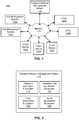
- FIG. 1illustrates one embodiment of a computing environment 100 associated with an aviation transport network.
- the computing environment 100includes a transport network management system 110 , a set of VTOL aircraft 120 a , 120 b , a set of hub management systems 130 a , 130 b , and a set of client devices 140 a , 140 b , 140 c , all connected via a network 170 .
- a network 170a network 170
- the computing environment 100contains different and/or additional elements.
- the functionsmay be distributed among the elements in a different manner than described.
- the hub management systems 130may be omitted with information about the hubs stored and updated at the transport network management system 110 .
- the transport network management system 110assists in the planning and design of the transport network.
- the transport network management system 110estimates demand for transport services, suggests locations for VTOL hubs to help meet that demand, and simulates the flow of riders and VTOL aircraft between the hubs to assist in network planning. Embodiments of the transport network management system 110 are described in greater detail below, with reference to FIGS. 2 through 6 .
- the transport network management system 110may also coordinate transport services once a set of VTOL hubs are operational.
- the transport network management system 110may pair users who request transport services (riders) with specific VTOL aircraft 120 .
- the transport network management system 110may also interact with ground-based transportation to coordinate travel services.
- the transport network management system 110may be an extension of an existing transport services coordinator, such as a ridesharing service.
- the transport network management system 110treats a journey involving a VTOL aircraft 120 as having three legs: (1) from the rider's initial location to a first hub; (2) from the first hub to a second hub in a VTOL; and (3) from the second hub to the rider's destination.
- the first and third legsmay be walking or provided by ground transportation, such as a ride-sharing service.
- the transport network management system 110provides routing information to VTOL aircraft 120 , such as what time to leave a current hub, which hub to fly to after departure, way points along the way, how long to spend charging before departure or on arrival, and the identity of individuals to carry.
- the transport network management system 110may also direct certain VTOL aircraft 120 to fly between hubs without riders to improve fleet distribution (referred to as “deadheading”).
- the VTOL aircraft 120are vehicles that fly between hubs in the transport network.
- a VTOL aircraft 120may be controlled by a human pilot (inside the vehicle or on the ground) or it may be autonomous.
- the VTOL aircraft 120are battery-powered aircraft that use a set of propellers for horizontal and vertical thrust.
- the configuration of the propellersenables the VTOL aircraft to take-off and land vertically (or substantially vertically).
- helicoptershelicopters, planes that take-off at angles other than vertical, and the like.
- the term VTOLshould be construed to include such vehicles.
- a VTOL aircraft 120may include a computer system that communicates status information (e.g., via the network 170 ) to other elements of the computing environment 100 .
- the status informationmay include current location, current battery charge, potential component failures, and the like.
- the computer system of the VTOL aircraft 120may also receive information, such as routing information and weather information. Although two VTOL aircraft 120 are shown in FIG. 1 , a transport network can include any number of VTOL aircraft.
- a hub management systems 130provides functionality at a hub in the transport network.
- a hubis a location at which VTOL aircraft 120 are intended to land (and take-off).
- there may be different types of hubwithin a transport network, there may be different types of hub.
- a hub in a central location with a large amount of rider throughputmight include sufficient infrastructure for sixteen (or more) VTOL aircraft 120 to simultaneously (or almost simultaneously) take off or land.
- such a hubmight include multiple charging stations for recharging battery-powered VTOL aircraft 120 .
- a hub located in a sparely populated suburbmight include infrastructure for a single VTOL aircraft 120 and have no charging station.
- the hub management system 130may be located at the hub or remotely and be connected via the network 170 . In the latter case, a single hub management system 130 may serve multiple hubs.
- a hub management system 130monitors the status of equipment at the hub and reports to the transport network management system 110 . For example, if there is a fault in a charging station, the hub management system 130 may automatically report that it is unavailable for charging VTOL aircraft 120 and request maintenance or a replacement. The hub management system 130 may also control equipment at the hub.
- a hubincludes one or more launch pads that may move from a takeoff/landing position to embarking/disembarking position. The hub management system 130 may control the movement of the launch pad (e.g., in response to instructions received from transport network management system 110 and/or a VTOL aircraft 120 ).
- the client devices 140are computing devices with which users may arrange transport services within the transport network. Although three client devices 140 are shown in FIG. 1 , in practice, there may be many more (e.g., thousands or millions of) client devices connected to the network 170 .
- the client devices 140are mobile devices (e.g., smartphones, tablets, etc.) running an application for arranging transport services.
- a userprovides a pickup location and destination within the application and the client device 140 sends a request for transport services to the transport network management system 110 .
- the usermay provide a destination and the pickup location is determined based on the user's current location (e.g., as determined from GPS data for the client device 140 ).
- the transport network management system 115may determine how to service transport requests.
- a transport requestcan be serviced by a combination of ground-based and aerial transportation.
- the transport network management system 110sends information about how the request will be serviced to the user's client device 140 (e.g., what vehicle the user should get into, directions on where to walk, if necessary, etc.).
- the network 170provides the communication channels via which the other elements of the networked computing environment 100 communicate.
- the network 170can include any combination of local area and/or wide area networks, using both wired and/or wireless communication systems.
- the network 170uses standard communications technologies and/or protocols.
- the network 170can include communication links using technologies such as Ethernet, 802.11, worldwide interoperability for microwave access (WiMAX), 3G, 4G, code division multiple access (CDMA), digital subscriber line (DSL), etc.
- networking protocols used for communicating via the network 170include multiprotocol label switching (MPLS), transmission control protocol/Internet protocol (TCP/IP), hypertext transport protocol (HTTP), simple mail transfer protocol (SMTP), and file transfer protocol (FTP).
- MPLSmultiprotocol label switching
- TCP/IPtransmission control protocol/Internet protocol
- HTTPhypertext transport protocol
- SMTPsimple mail transfer protocol
- FTPfile transfer protocol
- Data exchanged over the network 170may be represented using any suitable format, such as hypertext markup language (HTML) or extensible markup language (XML).
- HTMLhypertext markup language
- XMLextensible markup language
- all or some of the communication links of the network 170may be encrypted using any suitable technique or techniques.
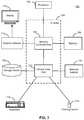
- FIG. 2illustrates one embodiment of the transport network management system 110 .
- the transport network management system 110includes a demand estimation subsystem 210 , a candidate hub identification subsystem 220 , a hub optimization subsystem 230 , and a route optimization subsystem 240 .
- the transport network management system 110contains different and/or additional elements.
- the functionsmay be distributed among the elements in a different manner than described.
- the transport network management system 110is depicted as connected to the network 170 , in some embodiments it is used for initial planning of the transport network and need not be connected to the other depicted components.
- the demand estimation subsystem 210predicts demand for transport services in a geographic region.
- the predicted demandmay be provided as input to the other subsystems to assist in the planning of the transport network.
- the demand estimation subsystem 210initially predicts demand based on usage data for one or more existing ground-based transportation services in the geographic region.
- the inputmay be a geographic region (e.g., a city) and time period, and the predicted demand may be a corresponding set of hypothetical transport requests, each including an origin, destination, and time.
- the model for predicting demandmay be updated over time based on usage data that includes flights between hubs in the transport network, as such data becomes available.
- usage datathat includes flights between hubs in the transport network, as such data becomes available.
- the candidate hub identification subsystem 220identifies a set of candidate locations for hubs within the geographic region.
- the candidate hub identification subsystem 220provides an interface with which a user, such as a transport network designer, can manually select candidate locations for hubs (e.g., by providing an address, GPS co-ordinates, clicking on the location on a map, etc.).
- the candidate hub identification subsystem 220may automatically identify candidate locations based on predicted demand (e.g., as produced by the demand estimation subsystem 210 ).
- predicted demande.g., as produced by the demand estimation subsystem 210 .
- the hub optimization subsystem 230takes the set of candidate locations for hubs and selects a subset of the locations at which hubs should actually be positioned based on the predicted demand. In one embodiment, the hub optimization subsystem 230 identifies an initial group of hub positions to make the transport network operational and one or more additional groups to be added later to improve the coverage of the network. The hub optimization subsystem 230 may also recommend a type for each hub (e.g., indicating a number of landing pads, a number of chargers, a number of VTOL aircraft storage bays, and the like). Various embodiments of the hub optimization subsystem 230 are described in greater detail below, with reference to FIG. 5 .
- the output from the hub optimizations subsystem 230may be fed into the route optimization subsystem 240 .
- the coverage provided by the hubs identified by the hub optimization subsystem 230provides an upper bound for throughput of the transport network. In other words, it is the maximum throughput achievable by placing hubs at the selected location assuming all qualifying transport requests are served by VTOL aircraft 120 . However, this upper bound may not be realized as it does not consider whether a VTOL aircraft 120 will be available to service any given transport request.
- the route optimization subsystem 240models the flow of VTOL aircraft 120 and riders through the transport network to determine how to manage the fleet of VTOL aircraft to realize close to the maximum throughput. Various embodiments of the route optimization subsystem 240 are described in greater detail below, with reference to FIG. 6 .
- FIG. 3illustrates one embodiment of the demand estimation subsystem 210 .
- the demand estimation subsystem 210predicts demand for transport services within a geographic region.
- the demand estimation subsystem 210includes an initial model module 310 , a demand prediction module 320 , a model update module 330 , and a demand data store 340 .
- the demand estimation subsystem 210contains different and/or additional elements.
- the functionsmay be distributed among the elements in a different manner than described.
- the demand estimation subsystem 210is used during planning of the transport network to generate an initial demand model and the model update module 330 may be omitted.
- the initial model module 310generates a model to predict demand for VTOL services within a geographic region.
- the modelmay be built using historical travel data including requests for transport services over a long distance within the geographic region using ground-based transportation (e.g., via a ride sharing service) as a proxy for demand for VTOL demand.
- the historical travel datamay be aggregated from multiple sources.
- a requestis considered long-distance where the Haversine distance between the origin and destination is between 20 and 100 miles.
- the initial model module 310may consider any such requests as being within the geographic region if either the origin or destination is within a given distance (e.g., 120 miles) of a predetermined point (e.g., a center point of the geographic region).
- the predetermined point and given distancemay be selected by the user.
- the usermay define a geofence and only requests for which the origin or destination (or both) are within the geofence are considered.
- other ways of determining which requests are considered to be within the geographic region and candidates for servicing with a VTOL aircraft 120may be used.
- the initial model module 310starts with a single estimate based on the historical travel data and uses a stochastic model (e.g., a two-phase stochastic model) to generate a more robust solution that accounts for multiple scenarios.
- a stochastic modele.g., a two-phase stochastic model
- a list of two or more scenariosare defined, each having a corresponding probability that it will occur.
- a set of hub locationsare selected (e.g., as described below, with reference to FIGS. 4 and 5 ).
- the initial model module 310then simulates servicing the predicted demand in view of the different scenarios and the corresponding probabilities.
- the demand estimation subsystem 210may analyze current demand data and compare it to the various scenarios to identify which is likely occurring.
- the demand estimation subsystem 210may then generate new or updated predictions of future demand based on the identified scenario.
- the modelcan also be refined to be more amenable to bad realizations of outcomes. For example, one configuration choice for the transport network might result on average in servicing a greater number of transport requests by VTOL 120 across all scenarios, but in one low probability scenario, the number of requests serviced by VTOL is very low. It may be preferable to select a second configuration in which the average number of requests serviced by VTOL 120 across all scenarios is lower, but there is no scenario where the level of service drops significantly below the average.
- the demand prediction module 320applies the model to predict demand for VTOL services in the geographic region during some time period.
- the userselects a start and end time for which a prediction is desired.
- Inputs to the modelmay include: current population of the geographic region, expected population growth of the geographic region, socioeconomics, locations of businesses and other entities (e.g., transport requests may be more often requested to and from airports, bars, venues, college campuses, etc.), and information about the cost, availability, and duration of other means of transport within the geographic region. If the transport network is already operational, the inputs may also include requests for transport services for the time period that have already been received and/or information about historical demand for transport services.
- the demand prediction module 320may apply machine-learning techniques to learn how current inputs (e.g., time of day, day of the week, date, weather, special events, number and distribution of requests for transport services already received for the time period, planned outages or limitations for other modes of transport, and the like) may be mapped to future demand.
- current inputse.g., time of day, day of the week, date, weather, special events, number and distribution of requests for transport services already received for the time period, planned outages or limitations for other modes of transport, and the like
- the output from the modelis a set of hypothetical transport requests that are candidates for being serviced at least in part with a VTOL aircraft 120 , each including an origin, destination, and time.
- a requestmay be considered eligible for servicing by a VTOL aircraft 120 if it would reduce the total travel time by a threshold amount (e.g., 40%) over servicing the request entirely with ground-based transportation.
- the demand estimation module 320periodically (e.g., every minute, every five minutes, etc.) estimates demand for a future window of time (e.g., the next hour, the next four hours, the next day, etc.).
- the model update module 330updates the model used to predict demand as new data becomes available.
- the model update module 330combines the historical travel data derived from ground-based services with travel data derived from requests actually serviced by VTOL aircraft 120 .
- the VTOL services datamay be weighted more heavily than the historical data to reflect the fact that it relates to actual VTOL demand rather than a proxy.
- the transport network management system 110may see an increase in requests for transport services over long-distances as the lower travel times that result from VTOL aircraft availability increase the attractiveness of long-distance travel to riders.
- the demand data store 340is one or more computer-readable media configured to store demand data. Although it is depicted as a single entity within the demand estimation subsystem 210 , it may be spread across multiple computing devices.
- the demand data store 340may be a distributed database that the demand estimation subsystem 210 accesses remotely via the network 170 .
- the demand data store 340stores the historical demand data used to build the initial model as well as the data describing actual VTOL services that may be used to update the model.
- the demand data store 340may also store the model itself.
- the transport network management system 110serves multiple geographic areas and the demand data store 340 stores different models for each geographic area. Multiple versions of each model may also be stored (e.g., to allow the demand estimation subsystem 210 to roll back to an earlier version if an updated model is found to be less accurate).
- FIG. 4illustrates one embodiment of the candidate hub identification subsystem 220 .
- the candidate hub identification subsystem 220identifies candidate locations for hubs at which VTOL aircraft 120 may take off and land.
- the candidate hub identification subsystem 220includes a parameter selection module 410 , a candidate selection module 420 , a candidate visualization module 430 , and a candidate hub store 440 .
- candidate hub identification subsystem 220contains different and/or additional elements.
- the functionsmay be distributed among the elements in a different manner than described. For example, some embodiments may omit the candidate visualization module 430 and corresponding functionality.
- the parameter selection module 410provides a user interface for selecting parameters to be used in identifying candidate locations for hubs.
- the parametersinclude the total number of candidate locations to identify, locations that must be considered candidates (e.g., by providing GPS coordinates, etc.), locations that cannot be considered (e.g., by defining a geofence around an excluded area).
- one or more of the parametersmay be predetermined.
- the number of candidate hubsmay be constrained to a fixed value (e.g., 100).
- the candidate selection module 420identifies a set of candidate locations for hubs based on estimated demand (e.g., as produced by the demand estimation subsystem 210 ) and the selected parameters.
- the candidate selection module 420applies a k-means clustering algorithm to the origins and destinations of the hypothetical transport requests generated by the demand estimation subsystem 210 .
- kmay be set to the total number of candidate locations desired or the total number less the number of candidate locations the user has indicated must be included.
- the candidate selection module 420identifies the centroid of each cluster as a candidate location for a hub. In other embodiments, other approaches may be used to identify candidate locations based on the estimated demand.
- the candidate visualization module 430presents the candidate locations to the user.
- the candidate visualization moduledisplays a map of the geographic region with the candidate locations overlaid (e.g., as black circles, etc.).
- the candidate visualization module 430may allow the user to add additional locations that must be considered, remove candidate locations generated by the candidate selection module 420 , and/or change the location of candidates.
- the visualizationmay also assist the user in modifying the parameters and rerunning the process of identifying candidate locations.
- the candidate hub store 440is one or more computer-readable media configured to store the candidate locations for hubs. It may also store a local copy of the data used the candidate hub identification subsystem 220 , such as estimated demand data. Although it is depicted as a single entity within the candidate hub identification subsystem 220 , it may be spread across multiple computing devices.
- FIG. 5illustrates one embodiment of the hub optimization subsystem 230 .
- the hub optimization subsystem 230assists with selecting which candidate locations for hubs to select to build hubs.
- the hub optimization subsystem 230includes a parameter selection module 510 , a hub selection module 520 , a hub classification module 530 , a hub visualization module 540 , and a hubs store 550 .
- the hub optimization subsystem 230contains different and/or additional elements.
- the functionsmay be distributed among the elements in a different manner than described. For example, some embodiments may omit the hub visualization module 540 and corresponding functionality.
- the parameter selection module 510provides a user interface for selecting parameters used in determining which candidate locations should be selected for building actual hubs.
- the usermay select between two objectives: maximizing the number of riders whose requests are covered by a hub or maximizing the total time saved using VTOL aircraft 120 .
- the usermay select a fixed number of hub locations (e.g., twenty-five) that should selected or the number may be left to be determined by the optimization objective.
- the usermay identify a number (or range) of hubs of different types that should be included (e.g., five large hubs with the capacity for sixteen VTOL aircraft 120 , charging equipment, and maintenance services; ten medium hubs with the capacity for four VTOL aircraft, and charging equipment; and ten small hubs with the capacity for one VTOL aircraft).
- the parameter selection module 510may also enable the user to identify multiple phases of construction, which may have different objectives. For example, a first phase might be restrained to twenty-five hubs with the goal of maximizing the number of riders served and a second phase might involve building another fifteen hubs with the goal of maximizing the amount of time saved. In other embodiments, different objectives or combinations of objectives may be set.
- the parameter selection module 510may also enable the user to set other parameters regarding the transport network.
- the usercan set a minimum distance (e.g., a Haversine distance) between hubs, a maximum distance VTOL aircraft 120 can travel without recharging, the rate at which a VTOL aircraft battery charges, whether the battery can be swapped (and how long it takes), a maximum airspeed of the VTOL aircraft, time taken to take off and land, time taken to load and unload riders, a threshold timesaving for a request to be considered eligible for service by VTOL, a number of riders a VTOL aircraft may carry at once, and curfew times (e.g., a period at night when VTOL aircraft are not allowed to fly), and the like.
- a minimum distancee.g., a Haversine distance
- VTOL aircraft 120can travel without recharging
- the rate at which a VTOL aircraft battery chargeswhether the battery can be swapped (and how long it takes)
- the transport networkmay include more than one type of VTOL aircraft 120 and the user may provide the parameters for each type.
- the usermay just select the type or types of VTOL aircraft 120 from a list (e.g., in a drop-down menu) and the parameter selection module 510 retrieves the corresponding information (maximum airspeed, maximum distance without recharging, number of riders that can be carried, etc.) from a data store.
- the hub selection module 520selects a subset of the candidate locations as recommended locations to construct hubs.
- the hub selection module 520retrieves predicted demand data (e.g., from the demand data store 340 ) that includes a set of hypothetical requests for transport services. Each hypothetical request includes an origin and a destination.
- the hub selection module 520identifies a subset of the candidate hubs that meets all of the provided parameters and best meets the selected objective.
- the hub selection module 520determines how to service each request.
- a requestwill either be serviced by a single leg on the ground (e.g., using a ridesharing service) or a set of three legs where the middle leg is serviced by a VTOL aircraft 120 .
- the first and third legsare ground-based, and can be walking legs or serviced by ground-based transportation.
- a given requestmay be a candidate for servicing by a VTOL aircraft 120 if the resulting time saving exceeds a threshold (e.g., 40%) over servicing the request entirely with ground-based transportation.
- the time taken for a VTOL-serviced legmay be estimated by multiplying the Haversine distance by a constant scaling factor (e.g., 1.42) to get a leg distance and assuming a typical airspeed (e.g., 170 miles per hour).
- a constant scaling factore.g., 1.42
- the first and third legsmay be considered candidates for being walking legs if they are less than a threshold distance (e.g., if the Haversine distance is less than 500 meters).
- the hub selection module 520may treat selection of the subset of hubs as a binary optimization problem. For example, define H as the set of candidate hubs each of which are either selected or not and R as the set of riders, indexed by r, each having a set of paths P(r). A path is an itinerary that contains a VTOL-serviced leg. Based on this, one may define three further variables:
- ⁇ r,pT ( o ( r ), d ( r )) ⁇ [ T ( o ( r ), h dep ( p ))+VTOL( h dep ( p ), h arr ( p ))+ T ( h arr ( p ), d ( r ))+ ⁇ ]
- T(i,j)is the estimated driving time from location i to j
- VTOL(i,j)is the estimated duration of taking a VTOL aircraft 120 from hub i to hub j
- ais a fixed number applied to all VTOL-serviced itineraries consisting of a load time, take off time, landing time, and unload time.
- o(r) and d(r)represent the origin and destination of rider r and h dep (p) and h arr (p) represent the departure and arrival hubs for path p.
- a penalty ⁇may be applied for any request not covered by a VTOL route. This leads to the following formulation of the optimization problem:
- constraint (1)seeks to maximize total duration savings for all riders in the network jointly by favoring assigning riders to itineraries with large time savings (first term) and by penalizing requests not serviced by VTOL aircraft 120 (second term).
- Constraint (2)ensures all riders are assigned either to a VTOL itinerary or are to remain on the ground.
- Constraint (3)ensures the number of hubs selected do not exceed the maximum allowable.
- Constraint (4)ensures riders are assigned only to itineraries for which both departure and arrival hubs are included in the selected subset. Notice that if either origin (i) or destination (j) hub are closed for path p this forces x r,p to be 0.
- Constraint (5)ensures that for any hubs that are too close together in a set, C, at most one of these hubs is chosen.
- This set of constraintsmay be solved by an integer program optimization solver to identify a subset of the candidate hubs that meets the applied constraints and achieves the selected objective.
- the balance between total time savings and VTOL aircraft 120 utilizationmay be altered by modifying the magnitude of the penalty applied for requests not serviced by a VTOL aircraft (e.g., by changing the value of ⁇ ). In other embodiments, other optimization processes may be used.
- the hub classification module 530assigns recommended types to the hubs in the subset identified by the hub selection module 520 .
- the hub classification module 530may define the expected throughout of each selected hub based on the itineraries that include the hub as either an origin or destination of a VTOL-serviced leg.
- the throughputmay be an average number of requests serviced per hour, per day, etc. Alternatively, the throughput may be an expected maximum number of requests serviced in a given time period (e.g., the number of expected requests in the busiest hour of the day for that hub, which may be different for different hubs).
- the hub classification module 530assigns a recommended type to each hub based on the expected throughputs.
- the typesmay be selected from a set of predetermined designs to provide uniformity and reduce design and construction costs. For example, there may be small, medium, and large hub designs, with the capacities to handle take off/landing of one, four, and sixteen VTOL aircraft 120 simultaneously (or approximately simultaneously), respectively.
- the hub classification module 530may assign a number of VTOL aircraft 120 that each hub should be able to take off/land simultaneously (or approximately simultaneously) at the hub. In either case, the classification may take into account a prediction of future growth in demand.
- the hub classification module 530may also indicate how many VTOL charging stations should be available at each hub (including zero).
- the charging facilities availableare tied to the type of the hub.
- a large hubmay have four charging stations, a medium hub one, and a small hub zero.
- the hub classification module 530may consider the distance between the hub and other hubs where charging stations are available. For example, a small hub located at the edge of the transport network, a large distance away from other hubs, may include a charging station even though most small hubs do not.
- the number or proportion of each type of hubis set by a user (e.g., via the parameter selection module 510 ) and the hub classification module 530 selects which hubs should be of which type accordingly. For example, if the user indicates that there should be five large hubs, the parameter selection module 510 might select the five hubs in the subset that have the largest throughput as the large hubs, etc.
- the hub visualization module 540presents the selected hub locations to the user.
- the hub visualization module 540overlays indicators of the selected hub locations on a map of the geographic region.
- the type of each hubmay be indicated by variations in size, color, shape, or the like of the indicators.
- each hub locationmay be indicated by a black circle with the size of the circle corresponding to the type of hub (e.g., a larger circle is a larger hub).
- the type of hub and/or additional informationmay be provided next to the indicator or in response to the user selecting the indicator (e.g., by clicking on it).
- a property of the indicatorsmay indicate which phase of construction each hub is in (e.g., the first phase hubs might be red while second phase hubs might be blue, etc.).
- the hub visualization module 540may also provide a user interface for altering the selected hub locations. For example, in one embodiment, the user can add, remove, or relocate hubs as well as change the type and construction phase of each hub.
- the hubs store 550is one or more computer-readable media configured to store the locations for hubs and corresponding data (e.g., types, throughput, etc.). It may also store a local copy of the candidate hub locations and/or estimated demand data for more efficient data processing. Although it is depicted as a single entity within the hub optimization subsystem 230 , it may be spread across multiple computing devices.
- FIG. 6illustrates one embodiment of the route optimization subsystem 240 .
- the route optimization subsystemdetermines the routing of VTOL aircraft 120 and riders through the transport network.
- the route optimization subsystem 240includes a parameter selection module 610 , a flow modelling module 620 , a route visualization module 630 , and a routing data store 640 .
- the route optimization subsystem 240contains different and/or additional elements.
- the functionsmay be distributed among the elements in a different manner than described.
- the parameter selection module 610(like its counterparts in the candidate hub identification subsystem 220 and hub optimization subsystem 230 ) provides a user interface for defining various parameters to be used in modelling the transport network.
- the definable parametersinclude VTOL parameters and objectives.
- the VTOL parametersmay include the number of available VTOL aircraft 120 and, where multiple types are available, their type or types. For each VTOL type, the VTOL parameters may include en route speed, time to ascend, number of seats, whether the VTOL aircraft is autonomous, maximum flying range, battery consumption rate when cruising, battery consumption for take-off and landing, battery recharging rate, whether the battery may be switched at a hub and how long switching takes, and the like.
- the parameter selection module 610may determine some or all of the parameters from data available from the VTOLs 120 and/or hub management systems 130 .
- the objectivemay be to: (1) maximize the number of people transported; (2) maximize use of VTOL aircraft 120 (e.g., use as few VTOL aircraft as possible while minimizing time each spends on the ground); or (3) minimize the total costs of operations, including passenger movement costs (e.g., a per-minute penalty for itineraries longer than the minimum possible), VTOL usage costs (e.g., a penalty for under-utilized VTOL legs), and VTOL aircraft repositioning costs (either to other hubs or within a hub, such as from a landing pad to a storage area). Other objectives and VTOL parameters may also be used.
- passenger movement costse.g., a per-minute penalty for itineraries longer than the minimum possible
- VTOL usage costse.g., a penalty for under-utilized VTOL legs
- VTOL aircraft repositioning costseither to other hubs or within a hub, such as from a landing pad to a storage area.
- Other objectives and VTOL parametersmay also be
- the flow modelling module 620models the flow of VTOL aircraft 120 and riders through the transport network, trying to maximize efficiency in view if the selected objective.
- the flow modelling module 620discretizes time into segments (e.g., one minute, five minutes, etc.) and calculates an optimum or substantially optimum routing for the fleet of VTOLs 120 for each segment.
- the flow modelling module 620solves the resulting multi-commodity network flow problem (riders and VTOL aircraft 120 are both commodities in the model) to determine how each VTOL aircraft should be routed to meet the selected objective.
- the network flow modelis defined as follows:
- the modelmay be defined by the following constraints:
- the network flow module 620may solve the model to meet a specified objective, such as:
- the model used by the network flow module 620may also be defined as a path-based model:
- the network flow module 620can determines how to route VTOL aircraft 120 through the transport network by finding the shortest path using negative weights and fuel constraints.
- the ground arcshave weights of ⁇ ij C ⁇ ⁇ ij and other arcs will have the weights ⁇ ij C ⁇ .
- the network flow module 620considers servicing each transport request via VTOL and each of multiple modes of ground transportation. The network flow module 620 may determine which mode of transport (including VTOL) is likely to be used to service each request.
- the network flow module 620may calculate a probability of each request being serviced by each mode of transport based on factors such as: the origin, the destination, the time, convenience (e.g., ingress and egress times), demographics, and the like. In other embodiments, different models for optimizing the routing may be used.
- the route visualization module 630presents the results of modelling the flow of VTOL aircraft 120 and riders within the transport network to the user.
- the resultsare presented as a set of summary statistics including the number of VTOL aircraft 120 in the fleet, a VTOL utilization percentage (e.g., the percentage of available seats on VTOL legs that were filled), an average time saved for requests serviced by VTOL aircraft (e.g., as a percentage of the ground-only equivalent time), the total number of riders served by VTOL aircraft in the period modelled.
- the summary statisticsmay include different or additional information.
- the route visualization module 630may present a timeline indicating how demand varied by hub and over time. In one embodiment, if the user selects a particular time (e.g., by clicking on the corresponding point on the timeline), the route visualization module 630 presents a visualization of state of the transport network at that time, such as by overlaying the flight path of each VTOL aircraft 120 in the air at that point over a map of the geographic area. Furthermore, if the user selects a hub, the route visualization module 630 may provide information about the selected hub, such as a number of incoming and outgoing VTOL aircraft 120 , a number of passengers waiting to board a VTOL aircraft at the hub, a number of unoccupied landing pads at the hub, and the like.
- information about the corresponding VTOL aircraft 120 and the flightpathmay be shown (e.g., an identifier of the particular VTOL aircraft, identifiers of the riders currently being serviced, origin and destination hubs, battery charge remaining, and time remaining to arrival).
- the visualizations provided by the route visualization module 630may help the user gain a deeper understanding of the transport network and identify potential problems and improvements before construction of the actual infrastructure begins. For example, the user may be able to identify potential choke points in the transport network, either in the form of overburdened hubs or time periods where demand is likely to exceed the number of available VTOL aircraft 120 . The visualizations may also help the user understand how much time will be saved for riders and how many riders will be served, which in turn may be used to estimate how traffic congestion may be alleviated.
- the routing data store 640stores data used and/or generated by the route optimization subsystem. In one embodiment, the routing data store 640 stores the results of each simulation performed by the flow modelling module 620 . Thus, a user may perform multiple simulations using different parameters and then compare the results at a later time.
- the routing data store 640may additionally or alternatively store local copies of the data used to model the transport network, such as the hub locations generated by the hub optimization subsystem 230 and the demand data generated by the demand estimation subsystem 210 .
- FIG. 7is a high-level block diagram illustrating an example computer 700 suitable for use within the computing environment 100 .
- the example computer 700includes at least one processor 702 coupled to a chipset 704 .
- the chipset 704includes a memory controller hub 720 and an input/output (I/O) controller hub 722 .
- a memory 706 and a graphics adapter 712are coupled to the memory controller hub 720 , and a display 718 is coupled to the graphics adapter 712 .
- a storage device 708 , keyboard 710 , pointing device 714 , and network adapter 716are coupled to the I/O controller hub 722 .
- Other embodiments of the computer 700have different architectures.
- the storage device 708is a non-transitory computer-readable storage medium such as a hard drive, compact disk read-only memory (CD-ROM), DVD, or a solid-state memory device.
- the memory 706holds instructions and data used by the processor 702 .
- the pointing device 714is a mouse, track ball, touch-screen, or other type of pointing device, and is used in combination with the keyboard 710 (which may be an on-screen keyboard) to input data into the computer system 700 .
- the graphics adapter 712displays images and other information on the display 718 .
- the network adapter 716couples the computer system 700 to one or more computer networks.
- the types of computers used by the entities of FIGS. 1 through 6can vary depending upon the embodiment and the processing power required by the entity.
- the transport services management system 110might include multiple computers 700 working together to provide the functionality described.
- the computers 700can lack some of the components described above, such as keyboards 710 , graphics adapters 712 , and displays 718 .
- FIG. 8illustrates one embodiment of a method 800 for planning an aviation transport network.
- the steps of FIG. 8are illustrated from the perspective of the transport network management system 110 performing the method 800 . However, some or all of the steps may be performed by other entities or components. In addition, some embodiments may perform the steps in parallel, perform the steps in different orders, or perform different steps.
- the method 800begins with the transport network management system 110 estimating 810 demand for long-distance (e.g., 20 to 120 miles) transport services.
- the estimated demandis a set of hypothetical transport requests, each including an origin, a destination, and a request time.
- the hypothetical transport requestsmay be based on historical requests for long-distance transport services using ground-based transportation.
- the historical requestsare used as the hypothetical requests.
- a set of hypothetical transport requestsis generated with a similar distribution as the historical requests, with adjustments applied for factors such as expected population growth, expected increase in demand once VTOL aircraft 120 become available, and the like.
- the transport network management system 110identifies 820 the candidate locations for hubs based on the estimated demand. As described previously, the transport network management system 110 may cluster the origins and destinations of transport requests (e.g., using k-mean clustering) and identify 820 the centroid of each cluster as a candidate location. In one embodiment, the transport network management system 110 identifies 820 one hundred candidate locations for hubs. In another embodiment, the number of hubs to identify is configurable by the user. The user may also be able to manually select or adjust one or more of the candidate locations.
- the transport network management system 110selects 830 a subset of the candidate locations as the locations for hubs. As described previously, the transport network management system 110 may select 830 the locations of the hubs to achieve one or more objectives, such as maximizing VTOL coverage, maximizing the reduction in travel time across the network, or minimizing a pre-defined cost function (e.g., to balance VTOL coverage with reductions in travel time). In one embodiment, the selected 830 locations are divided into different phases to be constructed at different times and which may serve different goals. For example, an initial twenty-five hubs might aim to maximize VTOL coverage while the next ten might aim to maximize savings in travel time. The number of hubs and phases may be predetermined or configurable by the user.
- the hubsmay also be of one or more types (e.g., large, medium, and small, each with a different number of landing pads, charging stations, etc.).
- the usermay also manually set or adjust the location and/or type selected for one or more hubs.
- the transport network management system 110calculates 840 route optimization statistics based on the selected information.
- the userdefines additional parameters, such as the number of VTOL aircraft 120 and information about the VTOL aircraft (e.g., number of seats, cruising speed, time required for take-off and landing, battery capacity, etc.).
- the transport network planning management 110determines the optimal routing for the VTOL aircraft 120 to meet the hypothetical demand and calculates 840 corresponding routing information.
- the route optimization statisticsmay include a percentage of the requests served by a VTOL aircraft 120 , the total time saved relative to using ground-based transportation alone, a total number of people served, an average number of empty seats on VTOL aircraft when flying, and the like. In other embodiments, different or additional information may be included in the route optimization statistics.
- the transport network management system 110presents 850 a visualization of the transport network to a user.
- the visualizationincludes a map of the geographic area served by the transport network with the hubs overlaid as geometric shapes (e.g., circles) at the corresponding locations.
- the visualizationmay also include the route optimization statistics (e.g., in a table).
- the visualizationmay include a time line indicating how demand varies over time, overlay some or all of the VTOL flight paths on the map, provide access to additional information about hubs and VTOL aircraft 120 (e.g., in response to clicking on the corresponding graphical representation in the visualization), and the like, as described previously.
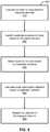
- FIG. 9illustrates one embodiment of a method 900 for determining routing for a fleet of VTOLs 120 within a transport network.
- the steps of FIG. 9are illustrated from the perspective of the transport network management system 110 performing the method 900 . However, some or all of the steps may be performed by other entities or components. In addition, some embodiments may perform the steps in parallel, perform the steps in different orders, or perform different steps.
- FIG. 9illustrates a single iteration of the method 900 .
- the method 900is repeated periodically (e.g., every minute, every five minutes, etc.) to update the routing data for the fleet of VTOLs 120 based on the current conditions. This may enable efficient use of the fleet, even in scenarios where there is a sudden change in conditions. For example, an unexpected failure in another mode of transport (e.g., a subway system shutting down due to an accident) may result in a sudden surge in requests for transport services that may be serviced by VTOL 120 , altering the optimal routing for the fleet.
- iterating the method 900may provide advantages including increasing the amount of time saved by riders, reduce the total amount of power used, reduce wear and tear on the VTOLs 120 , and the like.
- the method 900begins with the parameter selection module 610 retrieving 910 current VTOL and routing data.
- the VTOL datais information about each of the VTOLs 120 and may include: a current location, whether the VTOL is on the ground or in the air, a current battery level, a maximum battery level, and the like.
- the VTOL datamay be received from the VTOLs 120 (e.g., via a wireless connection) or estimated based on last know values (e.g., as reported by a hub management system 130 when the VTOL 120 was last connected to charge) and the routing data (e.g., a VTOL 120 that is in the air may be assumed to travel along an instructed route at a typical air speed to estimate its current location).
- the routing datais information about the routes assigned to each VTOL 120 .
- a routemay include information such as: a destination, way points to visit en route, a time to depart, a speed to fly at, an amount of time to spend charging before departure or after arrival, a number (and the identity) of riders to carry, and the like.
- the routing datamay be retrieved 910 from a data store (e.g., the routing data store 640 ).
- the parameter selection module 610also retrieves 920 current demand data.
- the current demand dataincludes requests for transport services that have already been sent by users.
- the current demand datais set a set of transport requests received from users (e.g., submitted from client devices 140 ), each including an origin, a destination, and a time of request.
- the parameter selection module 610supplements 930 the current demand data with an estimate of future demand.
- the estimate of future demandmay be generated using the demand estimation subsystem as described above, with reference to FIG. 3 .
- the current demand datamay be used as an input to the model used by the demand estimation subsystem 210 . For example, if the current demand is higher than usual for a given day and time, this may indicate that demand may continue to be higher than normal.
- the estimate of future demandis a set of hypothetical requests for transport services, each including an origin, a destination, and a time of request within a given time period (e.g., the next fifteen minutes, the next hour, the next four hours etc.).
- the estimate of future demandmay be combined with the current demand data to generate a single set of transport requests (both actual and hypothetical/expected).
- the demand datamay represent an estimate of demand for the time period that includes both transport requests that have already been received and a prediction of future transport requests.
- the route optimization subsystem 240updates 940 the routing data based on the demand data.
- the flow modelling module 620determines the optimum routing based on the demand data as well as the VTOL and routing data. This may be done using the optimization approaches described above, with reference to FIG. 6 .
- the input to the route optimization subsystem 240may include the retrieved 910 VTOL data, the demand data, weather data, and the like.
- the route optimization subsystem 240may send routing instructions to some or all of the VTOLs 120 .
- the instructionsmight direct a VTOL 120 to fly to a particular hub, charge its battery for a specified time, pick up specified riders, and perform other suitable activities to optimize the use of the VTOLs in the transport network.
- any reference to “one embodiment” or “an embodiment”means that a particular element, feature, structure, or characteristic described in connection with the embodiment is included in at least one embodiment.
- the appearances of the phrase “in one embodiment” in various places in the specificationare not necessarily all referring to the same embodiment.
- Coupledand “connected” along with their derivatives. It should be understood that these terms are not intended as synonyms for each other. For example, some embodiments may be described using the term “connected” to indicate that two or more elements are in direct physical or electrical contact with each other. In another example, some embodiments may be described using the term “coupled” to indicate that two or more elements are in direct physical or electrical contact. The term “coupled,” however, may also mean that two or more elements are not in direct contact with each other, but yet still co-operate or interact with each other. The embodiments are not limited in this context.
- the terms “comprises,” “comprising,” “includes,” “including,” “has,” “having” or any other variation thereof,are intended to cover a non-exclusive inclusion.
- a process, method, article, or apparatus that comprises a list of elementsis not necessarily limited to only those elements but may include other elements not expressly listed or inherent to such process, method, article, or apparatus.
- “or”refers to an inclusive or and not to an exclusive or. For example, a condition A or B is satisfied by any one of the following: A is true (or present) and B is false (or not present), A is false (or not present) and B is true (or present), and both A and B are true (or present).
Landscapes
- Engineering & Computer Science (AREA)
- General Physics & Mathematics (AREA)
- Physics & Mathematics (AREA)
- Aviation & Aerospace Engineering (AREA)
- Business, Economics & Management (AREA)
- Strategic Management (AREA)
- Marketing (AREA)
- Theoretical Computer Science (AREA)
- Economics (AREA)
- General Business, Economics & Management (AREA)
- Tourism & Hospitality (AREA)
- Health & Medical Sciences (AREA)
- General Health & Medical Sciences (AREA)
- Human Resources & Organizations (AREA)
- Primary Health Care (AREA)
- Accounting & Taxation (AREA)
- Development Economics (AREA)
- Finance (AREA)
- Entrepreneurship & Innovation (AREA)
- Data Mining & Analysis (AREA)
- Game Theory and Decision Science (AREA)
- Remote Sensing (AREA)
- Mechanical Engineering (AREA)
- Traffic Control Systems (AREA)
- Operations Research (AREA)
- Management, Administration, Business Operations System, And Electronic Commerce (AREA)
- Computer Networks & Wireless Communication (AREA)
- Signal Processing (AREA)
- Navigation (AREA)
- Computing Systems (AREA)
- Medical Informatics (AREA)
- Radio Relay Systems (AREA)
Abstract
Description
- 2) xr,pis a binary variable that equals 1 if rider r is assigned to path p from P(r) and 0 otherwise.
- 3) To account for the fact that not all requests may be covered depending upon the hubs chosen, yris another binary variable that equals 1 when rider r is not assigned a VTOL path and 0 otherwise.
τr,p=T(o(r),d(r))−[T(o(r),hdep(p))+VTOL(hdep(p),harr(p))+T(harr(p),d(r))+α]
Where T(i,j) is the estimated driving time from location i to j, VTOL(i,j) is the estimated duration of taking a VTOL aircraft120 from hub i to hub j, and a is a fixed number applied to all VTOL-serviced itineraries consisting of a load time, take off time, landing time, and unload time. Moreover o(r) and d(r) represent the origin and destination of rider r and hdep(p) and harr(p) represent the departure and arrival hubs for path p. To encourage servicing of as many requests as possible by VTOL120, a penalty λ may be applied for any request not covered by a VTOL route. This leads to the following formulation of the optimization problem:
- M: The set of VTOL aircraft.
- N: The set of all nodes.
- P: The set of passengers.
- H: The set of hubs.
- Sitn: The supply (+) or demand (−) or transit (0) of number of passengers o group n at hub i at time t.
- Vit: The supply (+) or demand (−) or transit (0) of number of VTOL aircraft at hub i at time t.
- (it,j
t ): Arc that travels from hub i at time t and arrives at hub j at timet . - In(it): The set of arcs coming into hub i at time t.
- Out(it): The set of arcs going out from hub i at time t.
- A: The set of all arcs (flight arcs and ground arcs).
- TA: The set of VTOL transit arcs.
- Gi: The set of ground arcs for the ithhub.
- U: The set of arcs for requests served by ground-based transport.
- T: The set of all time periods.
- xim: Whether VTOL aircraft m travels arc i.
- yip: The number of passengers in group p that travels arc i.
- zt′m: The battery level of VTOL aircraft m at time t.
- Ei: The battery consumption (if flying) or charging (if on the ground) for a VTOL aircraft to travel arc i.
- VC: The passenger capacity of a VTOL aircraft.
- HCi: The capacity of the ithhub.
- B: The max battery level of a VTOL aircraft.
- Ri: The cost of repositioning a VTOL aircraft by arc i.
- Ci: The cost of travelling arc i.
- 1. Max time savings
- 2. Max VTOL utilization
- 3. Minimize total cost (traveling cost, repositioning cost)
which results in a reduced cost per column of
Claims (19)
Priority Applications (5)
| Application Number | Priority Date | Filing Date | Title |
|---|---|---|---|
| US15/961,806US11145211B2 (en) | 2017-04-25 | 2018-04-24 | Efficient VTOL resource management in an aviation transport network |
| US16/460,447US10713957B2 (en) | 2017-04-25 | 2019-07-02 | Efficient VTOL resource management in an aviation transport network |
| US17/461,212US20220036740A1 (en) | 2017-04-25 | 2021-08-30 | Efficient VTOL Resource Management in an Aviation Transport Network |
| US17/514,823US12230146B2 (en) | 2017-04-25 | 2021-10-29 | Efficient VTOL resource management in an aviation transport network |
| US19/025,209US20250157341A1 (en) | 2017-04-25 | 2025-01-16 | Efficient VTOL Resource Management in an Aviation Transport Network |
Applications Claiming Priority (2)
| Application Number | Priority Date | Filing Date | Title |
|---|---|---|---|
| US201762489992P | 2017-04-25 | 2017-04-25 | |
| US15/961,806US11145211B2 (en) | 2017-04-25 | 2018-04-24 | Efficient VTOL resource management in an aviation transport network |
Related Child Applications (2)
| Application Number | Title | Priority Date | Filing Date |
|---|---|---|---|
| US16/460,447ContinuationUS10713957B2 (en) | 2017-04-25 | 2019-07-02 | Efficient VTOL resource management in an aviation transport network |
| US17/461,212ContinuationUS20220036740A1 (en) | 2017-04-25 | 2021-08-30 | Efficient VTOL Resource Management in an Aviation Transport Network |
Publications (2)
| Publication Number | Publication Date |
|---|---|
| US20180308366A1 US20180308366A1 (en) | 2018-10-25 |
| US11145211B2true US11145211B2 (en) | 2021-10-12 |
Family
ID=63854688
Family Applications (5)
| Application Number | Title | Priority Date | Filing Date |
|---|---|---|---|
| US15/961,806Active2039-03-31US11145211B2 (en) | 2017-04-25 | 2018-04-24 | Efficient VTOL resource management in an aviation transport network |
| US16/460,447ActiveUS10713957B2 (en) | 2017-04-25 | 2019-07-02 | Efficient VTOL resource management in an aviation transport network |
| US17/461,212PendingUS20220036740A1 (en) | 2017-04-25 | 2021-08-30 | Efficient VTOL Resource Management in an Aviation Transport Network |
| US17/514,823Active2039-08-11US12230146B2 (en) | 2017-04-25 | 2021-10-29 | Efficient VTOL resource management in an aviation transport network |
| US19/025,209PendingUS20250157341A1 (en) | 2017-04-25 | 2025-01-16 | Efficient VTOL Resource Management in an Aviation Transport Network |
Family Applications After (4)
| Application Number | Title | Priority Date | Filing Date |
|---|---|---|---|
| US16/460,447ActiveUS10713957B2 (en) | 2017-04-25 | 2019-07-02 | Efficient VTOL resource management in an aviation transport network |
| US17/461,212PendingUS20220036740A1 (en) | 2017-04-25 | 2021-08-30 | Efficient VTOL Resource Management in an Aviation Transport Network |
| US17/514,823Active2039-08-11US12230146B2 (en) | 2017-04-25 | 2021-10-29 | Efficient VTOL resource management in an aviation transport network |
| US19/025,209PendingUS20250157341A1 (en) | 2017-04-25 | 2025-01-16 | Efficient VTOL Resource Management in an Aviation Transport Network |
Country Status (7)
| Country | Link |
|---|---|
| US (5) | US11145211B2 (en) |
| EP (1) | EP3616157A4 (en) |
| JP (1) | JP7108158B2 (en) |
| KR (1) | KR102433739B1 (en) |
| CN (1) | CN110663221A (en) |
| AU (1) | AU2018260459B2 (en) |
| WO (1) | WO2018198038A1 (en) |
Cited By (21)
| Publication number | Priority date | Publication date | Assignee | Title |
|---|---|---|---|---|
| US20210065113A1 (en)* | 2019-08-30 | 2021-03-04 | International Business Machines Corporation | Secure, Private Market Share Augmentation with Simultaneous Operational Efficiency Improvements for Delivery Providers on a Network |
| US11900819B2 (en) | 2018-04-24 | 2024-02-13 | Joby Aero, Inc. | Determining VTOL departure time in an aviation transport network for efficient resource management |
| US11955017B2 (en) | 2018-05-07 | 2024-04-09 | Joby Aero, Inc. | Dynamic aircraft routing |
| US12012229B2 (en) | 2020-03-06 | 2024-06-18 | Joby Aero, Inc. | System and method for robotic charging aircraft |
| US12057021B2 (en) | 2018-05-07 | 2024-08-06 | Joby Aero, Inc. | Dynamic aircraft routing |
| US12140438B2 (en) | 2019-03-18 | 2024-11-12 | Joby Aero, Inc. | Multi-modal transportation service planning and fulfillment |
| US12157580B2 (en) | 2020-04-29 | 2024-12-03 | Joby Aero, Inc. | Systems and methods for transferring aircraft |
| US12175396B2 (en) | 2020-09-01 | 2024-12-24 | Joby Aero, Inc. | Systems and methods for facilitating aerial vehicle services |
| US12187409B2 (en) | 2017-08-02 | 2025-01-07 | Joby Aero, Inc. | VTOL aircraft for network system |
| US12211392B2 (en) | 2019-12-31 | 2025-01-28 | Joby Aero, Inc. | Systems and methods for providing aircraft sensory cues |
| US12230146B2 (en) | 2017-04-25 | 2025-02-18 | Joby Aero, Inc. | Efficient VTOL resource management in an aviation transport network |
| US12242283B2 (en) | 2018-05-07 | 2025-03-04 | Joby Aero, Inc. | System and method for landing and storing vertical take-off and landing aircraft |
| US12254777B2 (en) | 2020-05-28 | 2025-03-18 | Joby Aero, Inc. | Cloud service integration with onboard vehicle system |
| US12269603B2 (en) | 2019-04-23 | 2025-04-08 | Joby Aero, Inc. | Vehicle cabin thermal management system and method |
| US12330524B2 (en) | 2023-10-16 | 2025-06-17 | Archer Aviation, Inc. | Systems and methods for high voltage battery charging and vertiport operations |
| US12339661B2 (en) | 2019-11-06 | 2025-06-24 | Joby Aero, Inc. | Aerial ride quality improvement system using feedback |
| US12367539B2 (en) | 2020-03-25 | 2025-07-22 | Joby Aero, Inc. | Systems and methods for generating flight plans used by a ride sharing network |
| US12372978B2 (en) | 2021-07-02 | 2025-07-29 | Joby Aero, Inc. | Vehicle autonomy architecture |
| US12387607B2 (en) | 2020-12-10 | 2025-08-12 | Joby Aero, Inc. | Unmanned aircraft control using ground control station |
| US12400160B2 (en) | 2020-05-07 | 2025-08-26 | Joby Aero, Inc. | Systems and methods for simulating aircraft systems |
| US12442645B2 (en) | 2020-11-09 | 2025-10-14 | Joby Aero, Inc. | Multi-modal transportation service planning and fulfillment |
Families Citing this family (24)
| Publication number | Priority date | Publication date | Assignee | Title |
|---|---|---|---|---|
| US20190114595A1 (en)* | 2017-10-17 | 2019-04-18 | Mitsubishi Electric Research Laboratories, Inc. | Systems and Methods for Joint Control of Multi-Modal Transportation Networks |
| JP6894418B2 (en)* | 2018-10-31 | 2021-06-30 | トヨタ自動車株式会社 | Demand forecast information display control method, display control device, and display control program |
| CN111242523A (en)* | 2018-11-29 | 2020-06-05 | 顺丰科技有限公司 | Method, device, server and storage medium for determining air transportation path |
| GB201820986D0 (en)* | 2018-12-21 | 2019-02-06 | Tevva Motors Ltd | Systems and methods of implementing virtual congestion and clean air zones |
| JP2022534811A (en)* | 2019-06-07 | 2022-08-03 | ジョビー エレベート, インコーポレイテッド | Routing based on vehicle characteristics |
| US11900818B2 (en) | 2019-06-10 | 2024-02-13 | Joby Aero, Inc. | Time varying loudness prediction system |
| EP3815010A1 (en) | 2019-06-10 | 2021-05-05 | Uber Technologies, Inc. | Distributed weight measurement using integrated load cells |
| CN110321095B (en)* | 2019-07-23 | 2023-06-06 | 海南太美航空股份有限公司 | Terminal, system and method for displaying route information |
| CN113128817B (en)* | 2020-01-10 | 2024-07-02 | 宝马股份公司 | Transport control method and transport control system based on aircraft |
| US20210374627A1 (en)* | 2020-05-28 | 2021-12-02 | Eric Mueller | Periodic vertiport usage and capacity data exchange |
| JP2022019193A (en)* | 2020-07-17 | 2022-01-27 | トヨタ自動車株式会社 | Mobility service provision method, mobility service system, and management server |
| JP7331805B2 (en)* | 2020-08-19 | 2023-08-23 | トヨタ自動車株式会社 | MOBILITY SERVICE SYSTEM, MOBILITY SERVICE PROVISION METHOD, AND MANAGEMENT SERVER |
| JP7384124B2 (en)* | 2020-08-19 | 2023-11-21 | トヨタ自動車株式会社 | Electric vertical takeoff and landing aircraft and information provision method |
| JP7405040B2 (en)* | 2020-08-19 | 2023-12-26 | トヨタ自動車株式会社 | Mobility service system, mobility service provision method, and management server |
| WO2022051504A1 (en)* | 2020-09-02 | 2022-03-10 | Joby Elevate, Inc. | System and method for reducing choke points associated with switching between transportation modes of a multi-modal transportation service |
| US20220113147A1 (en)* | 2020-10-12 | 2022-04-14 | Joby Elevate, Inc. | Systems and Methods for Mitigating Third Party Contingencies |
| US20220114506A1 (en)* | 2020-10-12 | 2022-04-14 | Joby Elevate, Inc. | Systems and Methods for Optimizing Multi-Modal Transportation |
| US20220147884A1 (en)* | 2020-11-10 | 2022-05-12 | Uber Technologies, Inc. | Systems and Methods for Nonconforming Service Facilitation for Multi-Modal Services |
| US11340308B1 (en)* | 2021-04-27 | 2022-05-24 | Beta Air, Llc | System and method for state determination of a battery module configured for used in an electric vehicle |
| US11373543B1 (en) | 2021-07-12 | 2022-06-28 | Beta Air, Llc | Systems and methods for optimization of a recharging flight plan for an electric vertical takeoff and landing aircraft |
| US20230186209A1 (en)* | 2021-12-10 | 2023-06-15 | Ford Global Technologies, Llc | Systems and methods to define, rebalance, and repurpose a fleet of vehicles |
| US11710413B1 (en) | 2021-12-29 | 2023-07-25 | Beta Air, Llc | System for flight plan generation of an electric vertical takeoff and landing (eVTOL) aircraft and a method for its use |
| CN114720887A (en)* | 2022-03-29 | 2022-07-08 | 上海沃兰特航空技术有限责任公司 | Airplane endurance estimation method and device, electronic equipment and storage medium |
| CN119049344A (en)* | 2024-08-23 | 2024-11-29 | 天翼物联科技有限公司 | Urban low-empty-carrier flight bus system, flight method, equipment and medium |
Citations (23)
| Publication number | Priority date | Publication date | Assignee | Title |
|---|---|---|---|---|
| JP2010095246A (en) | 2008-10-20 | 2010-04-30 | Honeywell Internatl Inc | System and method for navigation of unmanned aerial vehicles |
| US20130144831A1 (en) | 2011-12-05 | 2013-06-06 | FasterFare, LLC | Predicting Taxi Utilization Information |
| US9301099B2 (en)* | 2009-10-29 | 2016-03-29 | Tomtom North America, Inc. | Method of analyzing points of interest with probe data |
| WO2016093905A1 (en) | 2014-08-29 | 2016-06-16 | Tzunum Aircraft Llc | System and methods for implementing regional air transit network using hybrid-electric aircraft |
| US20160244158A1 (en) | 2013-08-13 | 2016-08-25 | Usa As Represented By The Administrator Of The National Aeronautics And Space Adminstration | Vertical take-off and landing vehicle with increased cruise efficiency |
| US20160311529A1 (en)* | 2013-12-18 | 2016-10-27 | Neva Aerospace, Ltd. | Modular Electric VTOL Aircraft |
| US9550577B1 (en)* | 2014-06-26 | 2017-01-24 | Amazon Technologies, Inc. | Electricity generation in automated aerial vehicles |
| US20170021941A1 (en) | 2015-02-11 | 2017-01-26 | Aerovironment, Inc. | Pod operating system for a vertical take-off and landing (vtol) unmanned aerial vehicle (uav) |
| US20170057650A1 (en)* | 2014-06-20 | 2017-03-02 | Dale Martin Walter-Robinson | Energy Cell Regenerative System For Electrically Powered Aircraft |
| US20170090484A1 (en) | 2015-09-29 | 2017-03-30 | T-Mobile U.S.A., Inc. | Drone-based personal delivery system |
| US20170097240A1 (en) | 2015-10-06 | 2017-04-06 | Honda Motor Co., Ltd. | Motorcycle organic gathering for route sharing |
| US20170169366A1 (en) | 2015-12-14 | 2017-06-15 | Google Inc. | Systems and Methods for Adjusting Ride-Sharing Schedules and Routes |
| US20170197710A1 (en) | 2015-09-07 | 2017-07-13 | Tao Ma | Passenger transport systems based on pilotless vertical takeoff and landing (vtol) aircraft |
| US20170357914A1 (en)* | 2016-06-10 | 2017-12-14 | Conduent Business Services, Llc | System and method for optimal automated booking of on-demand transportation in multi-modal journeys |
| US20180081360A1 (en)* | 2016-09-20 | 2018-03-22 | International Business Machines Corporation | Managing Autonomous Vehicles Needing Energy Replenishment |
| US20180208305A1 (en)* | 2016-10-31 | 2018-07-26 | Bell Helicopter Textron Inc. | Vertical Takeoff and Landing (VTOL) Aircraft |
| US20180305005A1 (en)* | 2017-04-24 | 2018-10-25 | AFS-DV VTOL Technologies Corporation | Vertical Take-Off and Landing Aircraft |
| WO2018198038A1 (en) | 2017-04-25 | 2018-11-01 | Uber Technologies, Inc. | Efficient vtol resource management in an aviation transport network |
| US20190012909A1 (en)* | 2016-01-03 | 2019-01-10 | Yosef Mintz | System and methods to apply robust predictive traffic load balancing control and robust cooperative safe driving for smart cities |
| US10384692B2 (en)* | 2017-03-16 | 2019-08-20 | Amazon Technologies, Inc. | Demand-based distribution of items using intermodal carriers and unmanned aerial vehicles |
| US20190325757A1 (en) | 2018-04-24 | 2019-10-24 | Uber Technologies, Inc. | Determining vtol departure time in an aviation transport network for efficient resource management |
| US10627524B2 (en)* | 2016-12-06 | 2020-04-21 | At&T Intellectual Property I, L.P. | Method and apparatus for positioning via unmanned aerial vehicles |
| US10663529B1 (en)* | 2015-09-25 | 2020-05-26 | Amazon Technologies, Inc. | Automatic battery charging |
Family Cites Families (71)
| Publication number | Priority date | Publication date | Assignee | Title |
|---|---|---|---|---|
| US3035789A (en) | 1957-11-27 | 1962-05-22 | Arthur M Young | Convertiplane |
| US4022405A (en) | 1976-03-25 | 1977-05-10 | The United States Of America As Represented By The Secretary Of The Navy | Fan lift-cruise v/stol aircraft |
| US5842667A (en) | 1994-03-31 | 1998-12-01 | Jones; Tommy Lee | Vertical takeoff and landing mass transit system and method |
| US6343127B1 (en) | 1995-09-25 | 2002-01-29 | Lord Corporation | Active noise control system for closed spaces such as aircraft cabin |
| US5823468A (en) | 1995-10-24 | 1998-10-20 | Bothe; Hans-Jurgen | Hybrid aircraft |
| US5839691A (en) | 1996-05-22 | 1998-11-24 | Lariviere; Jean Soulez | Vertical takeoff and landing aircraft |
| JP2968511B2 (en) | 1998-03-25 | 1999-10-25 | 株式会社コミュータヘリコプタ先進技術研究所 | Helicopter low-noise landing gear and low-noise landing system |
| US20100079342A1 (en) | 1999-03-05 | 2010-04-01 | Smith Alexander E | Multilateration enhancements for noise and operations management |
| JP2003137192A (en) | 2001-10-31 | 2003-05-14 | Mitsubishi Heavy Ind Ltd | Vertical taking-off/landing craft |
| BRPI0708425A2 (en) | 2006-03-01 | 2011-05-31 | Urban Aeronautics Ltd | ground effect reeds |
| US8016226B1 (en) | 2007-07-10 | 2011-09-13 | Wood Victor A | Vertical take off and landing aircraft system with energy recapture technology |
| US8311686B2 (en) | 2009-08-20 | 2012-11-13 | The Boeing Company | Onboard airplane community noise and emissions monitor |
| US20110042510A1 (en) | 2009-08-24 | 2011-02-24 | Bevirt Joeben | Lightweight Vertical Take-Off and Landing Aircraft and Flight Control Paradigm Using Thrust Differentials |
| US8737634B2 (en) | 2011-03-18 | 2014-05-27 | The United States Of America As Represented By The Secretary Of The Navy | Wide area noise cancellation system and method |
| WO2013106009A1 (en) | 2011-03-28 | 2013-07-18 | Rolls-Royce North American Technologies Inc. | Aircraft and airborne electrical power and thermal management system |
| JP5822923B2 (en) | 2011-06-01 | 2015-11-25 | 三菱航空機株式会社 | Aircraft tilt detection apparatus and cargo loading / unloading method using the same |
| DE102011105880B4 (en) | 2011-06-14 | 2014-05-08 | Eads Deutschland Gmbh | Electric drive device for an aircraft |
| US9786961B2 (en) | 2011-07-25 | 2017-10-10 | Lightening Energy | Rapid charging electric vehicle and method and apparatus for rapid charging |
| FR2979993B1 (en) | 2011-09-09 | 2013-09-20 | Airbus Operations Sas | METHOD AND DEVICE FOR AUTOMATICALLY ESTIMATING AIR SPEED OF AN AIRCRAFT |
| US20130092791A1 (en) | 2011-10-18 | 2013-04-18 | General Electric Company | Method for a noise abatement procedure for an aircraft |
| EP2817219B1 (en) | 2012-02-22 | 2020-06-03 | Volocopter GmbH | Aircraft |
| EP2698749A1 (en) | 2012-08-14 | 2014-02-19 | Amadeus s.a.s. | Passenger oriented seating system and method |
| US9816529B2 (en) | 2013-03-15 | 2017-11-14 | Kcf Technologies, Inc. | Propeller sound field modification systems and methods |
| US20180216988A1 (en) | 2013-10-01 | 2018-08-02 | C. Kirk Nance | Method and apparatus for monitoring and avoidance of unanticipated loads applied to aircraft landing gear |
| CA2927096C (en)* | 2013-10-26 | 2023-02-28 | Amazon Technologies, Inc. | Unmanned aerial vehicle delivery system |
| US9694911B2 (en) | 2014-03-18 | 2017-07-04 | Joby Aviation, Inc. | Aerodynamically efficient lightweight vertical take-off and landing aircraft with pivoting rotors and stowing rotor blades |
| US9165471B1 (en)* | 2014-03-28 | 2015-10-20 | General Electric Company | System and method for determining aircraft payloads to enhance profitability |
| US9334052B2 (en)* | 2014-05-20 | 2016-05-10 | Verizon Patent And Licensing Inc. | Unmanned aerial vehicle flight path determination, optimization, and management |
| US9671790B2 (en)* | 2014-05-20 | 2017-06-06 | Verizon Patent And Licensing Inc. | Scheduling of unmanned aerial vehicles for mission performance |
| US9550561B1 (en) | 2014-08-11 | 2017-01-24 | Amazon Technologies, Inc. | Determining center of gravity of an automated aerial vehicle and a payload |
| US9435661B2 (en) | 2014-10-08 | 2016-09-06 | Honeywell International Inc. | Systems and methods for attitude fault detection based on air data and aircraft control settings |
| US9387928B1 (en) | 2014-12-18 | 2016-07-12 | Amazon Technologies, Inc. | Multi-use UAV docking station systems and methods |
| US9838436B2 (en) | 2015-03-30 | 2017-12-05 | Gulfstream Aerospace Corporation | Aircraft data networks |
| CN104807457A (en)* | 2015-04-29 | 2015-07-29 | 广州快飞计算机科技有限公司 | Generation method and device of flight line of aircraft and terminal equipment |
| US9953540B2 (en)* | 2015-06-16 | 2018-04-24 | Here Global B.V. | Air space maps |
| US9422055B1 (en) | 2015-09-02 | 2016-08-23 | Amazon Technologies, Inc. | Unmanned aerial vehicle motor driving randomization for noise abatement |
| US9415870B1 (en) | 2015-09-02 | 2016-08-16 | Amazon Technologies, Inc. | Unmanned aerial vehicle motor driving randomization and feedback for noise abatement |
| US9442496B1 (en) | 2015-09-18 | 2016-09-13 | Amazon Technologies, Inc. | Active airborne noise abatement |
| EP3374263A4 (en)* | 2015-11-10 | 2019-05-08 | Matternet, Inc. | METHODS AND TRANSPORT SYSTEMS USING PILOT-FREE AIR VEHICLES |
| CN105427003A (en)* | 2015-12-30 | 2016-03-23 | 北京航空航天大学 | Travel demand analysis-based bus station point deployment method |
| KR20170080354A (en)* | 2015-12-31 | 2017-07-10 | 자이로캠주식회사 | The virtual skyway and air traffic control system for the drone's safe flight or the drone navigation system or service |
| US10304344B2 (en) | 2016-02-09 | 2019-05-28 | Honeywell International Inc. | Methods and systems for safe landing at a diversion airport |
| WO2018009914A2 (en) | 2016-07-07 | 2018-01-11 | Zunum Aero, Inc. | Systems and methods for implementing multi-modal transport |
| US20180018887A1 (en) | 2016-07-18 | 2018-01-18 | Honeywell International Inc. | Routing aircraft ground movements at an airport |
| US10249200B1 (en) | 2016-07-22 | 2019-04-02 | Amazon Technologies, Inc. | Deployable delivery guidance |
| WO2018023556A1 (en) | 2016-08-04 | 2018-02-08 | SZ DJI Technology Co., Ltd. | Methods and systems for obstacle identification and avoidance |
| US10140873B2 (en) | 2016-08-16 | 2018-11-27 | The Boeing Company | Performance-based track variation for aircraft flight management |
| US10152894B2 (en) | 2016-08-24 | 2018-12-11 | The Boeing Company | Community noise management with aircraft dynamic path variation |
| US10207805B2 (en)* | 2017-01-06 | 2019-02-19 | Michael Steward Evans | Drone transport system |
| CN110546068B (en) | 2016-11-02 | 2023-05-26 | 杰欧比航空有限公司 | VTOL aircraft using rotors to simulate rigid wing aerodynamics |
| WO2018110598A1 (en) | 2016-12-13 | 2018-06-21 | 株式会社自律制御システム研究所 | Unmanned aircraft, device for controlling unmanned aircraft, method for controlling unmanned aircraft, and device for detecting failure of unmanned aircraft |
| US10836470B2 (en) | 2017-03-27 | 2020-11-17 | Anshuo Liu | Lopsided payload carriage gimbal for air and water-borne vehicles |
| US10832581B2 (en) | 2017-03-31 | 2020-11-10 | General Electric Company | Flight management via model-based iterative optimization |
| FR3065518B1 (en) | 2017-04-20 | 2019-07-05 | Liebherr-Aerospace Toulouse Sas | METHOD AND DEVICE FOR THERMALLY CONTROLLING A PLURALITY OF CABINS OF A VEHICLE |
| US10399689B2 (en) | 2017-06-07 | 2019-09-03 | Ge Aviation Systems Llc | Optimizing aircraft control based on noise abatement volumes |
| US10768201B2 (en) | 2017-06-12 | 2020-09-08 | The Boeing Company | System for estimating airspeed of an aircraft based on a drag model |
| US10330482B2 (en) | 2017-07-28 | 2019-06-25 | Uber Technologies, Inc. | Dynamically determining origin and destination locations for a network system |
| US10948910B2 (en) | 2017-09-07 | 2021-03-16 | Qualcomm Incorporated | Robotic vehicle separated payload detection and response |
| CA3080796A1 (en) | 2017-11-02 | 2019-05-09 | Peter F. SHANNON | Vertiport management platform |
| US10759537B2 (en) | 2017-11-03 | 2020-09-01 | Uber Technologies, Inc. | Safe vertical take-off and landing aircraft payload assignment |
| US10913528B1 (en) | 2017-11-03 | 2021-02-09 | Uber Technologies, Inc. | Safe vertical take-off and landing aircraft payload distribution and adjustment |
| US20190146508A1 (en) | 2017-11-14 | 2019-05-16 | Uber Technologies, Inc. | Dynamic vehicle routing using annotated maps and profiles |
| EP3499634A1 (en) | 2017-12-14 | 2019-06-19 | Mahle International GmbH | Battery thermal management system for a vehicle |
| US20190316849A1 (en) | 2018-04-11 | 2019-10-17 | Nio Usa, Inc. | Thermal management, heat transfer improvement of radiator and condenser using ac system evaporator's condensation |
| DE112018007300T5 (en)* | 2018-04-16 | 2020-12-10 | Ford Global Technologies, Llc | ROUTE GUIDANCE WITH PERCEPTION OF THE SURROUNDINGS |
| US10593215B2 (en) | 2018-05-07 | 2020-03-17 | Uber Technologies, Inc. | Dynamic aircraft routing |
| US11238745B2 (en) | 2018-05-07 | 2022-02-01 | Joby Aero, Inc. | Dynamic aircraft routing |
| CN116646641B (en) | 2019-04-23 | 2024-09-13 | 杰欧比飞行有限公司 | Battery thermal management system and method |
| US11900818B2 (en) | 2019-06-10 | 2024-02-13 | Joby Aero, Inc. | Time varying loudness prediction system |
| WO2020252024A1 (en) | 2019-06-11 | 2020-12-17 | Uber Technologies, Inc. | Dynamic aircraft routing |
| CN110632210A (en) | 2019-10-14 | 2019-12-31 | 普洱市质量技术监督综合检测中心 | Sample pretreatment method and detection method for determining aflatoxin B1 content in Pu' er tea by liquid chromatography-mass spectrometry |
- 2018
- 2018-04-24USUS15/961,806patent/US11145211B2/enactiveActive
- 2018-04-25WOPCT/IB2018/052864patent/WO2018198038A1/ennot_activeCeased
- 2018-04-25AUAU2018260459Apatent/AU2018260459B2/enactiveActive
- 2018-04-25KRKR1020197034711Apatent/KR102433739B1/enactiveActive
- 2018-04-25EPEP18790347.1Apatent/EP3616157A4/enactivePending
- 2018-04-25JPJP2019558428Apatent/JP7108158B2/enactiveActive
- 2018-04-25CNCN201880034496.0Apatent/CN110663221A/enactivePending
- 2019
- 2019-07-02USUS16/460,447patent/US10713957B2/enactiveActive
- 2021
- 2021-08-30USUS17/461,212patent/US20220036740A1/enactivePending
- 2021-10-29USUS17/514,823patent/US12230146B2/enactiveActive
- 2025
- 2025-01-16USUS19/025,209patent/US20250157341A1/enactivePending
Patent Citations (28)
| Publication number | Priority date | Publication date | Assignee | Title |
|---|---|---|---|---|
| JP2010095246A (en) | 2008-10-20 | 2010-04-30 | Honeywell Internatl Inc | System and method for navigation of unmanned aerial vehicles |
| US9301099B2 (en)* | 2009-10-29 | 2016-03-29 | Tomtom North America, Inc. | Method of analyzing points of interest with probe data |
| US20130144831A1 (en) | 2011-12-05 | 2013-06-06 | FasterFare, LLC | Predicting Taxi Utilization Information |
| US20160244158A1 (en) | 2013-08-13 | 2016-08-25 | Usa As Represented By The Administrator Of The National Aeronautics And Space Adminstration | Vertical take-off and landing vehicle with increased cruise efficiency |
| US20160311529A1 (en)* | 2013-12-18 | 2016-10-27 | Neva Aerospace, Ltd. | Modular Electric VTOL Aircraft |
| US20170057650A1 (en)* | 2014-06-20 | 2017-03-02 | Dale Martin Walter-Robinson | Energy Cell Regenerative System For Electrically Powered Aircraft |
| US9550577B1 (en)* | 2014-06-26 | 2017-01-24 | Amazon Technologies, Inc. | Electricity generation in automated aerial vehicles |
| WO2016093905A1 (en) | 2014-08-29 | 2016-06-16 | Tzunum Aircraft Llc | System and methods for implementing regional air transit network using hybrid-electric aircraft |
| US20170021941A1 (en) | 2015-02-11 | 2017-01-26 | Aerovironment, Inc. | Pod operating system for a vertical take-off and landing (vtol) unmanned aerial vehicle (uav) |
| US20170197710A1 (en) | 2015-09-07 | 2017-07-13 | Tao Ma | Passenger transport systems based on pilotless vertical takeoff and landing (vtol) aircraft |
| US10663529B1 (en)* | 2015-09-25 | 2020-05-26 | Amazon Technologies, Inc. | Automatic battery charging |
| US20170090484A1 (en) | 2015-09-29 | 2017-03-30 | T-Mobile U.S.A., Inc. | Drone-based personal delivery system |
| US20170097240A1 (en) | 2015-10-06 | 2017-04-06 | Honda Motor Co., Ltd. | Motorcycle organic gathering for route sharing |
| US20170169366A1 (en) | 2015-12-14 | 2017-06-15 | Google Inc. | Systems and Methods for Adjusting Ride-Sharing Schedules and Routes |
| US20190012909A1 (en)* | 2016-01-03 | 2019-01-10 | Yosef Mintz | System and methods to apply robust predictive traffic load balancing control and robust cooperative safe driving for smart cities |
| US20170357914A1 (en)* | 2016-06-10 | 2017-12-14 | Conduent Business Services, Llc | System and method for optimal automated booking of on-demand transportation in multi-modal journeys |
| US20180081360A1 (en)* | 2016-09-20 | 2018-03-22 | International Business Machines Corporation | Managing Autonomous Vehicles Needing Energy Replenishment |
| US20180208305A1 (en)* | 2016-10-31 | 2018-07-26 | Bell Helicopter Textron Inc. | Vertical Takeoff and Landing (VTOL) Aircraft |
| US10627524B2 (en)* | 2016-12-06 | 2020-04-21 | At&T Intellectual Property I, L.P. | Method and apparatus for positioning via unmanned aerial vehicles |
| US10384692B2 (en)* | 2017-03-16 | 2019-08-20 | Amazon Technologies, Inc. | Demand-based distribution of items using intermodal carriers and unmanned aerial vehicles |
| US20180305005A1 (en)* | 2017-04-24 | 2018-10-25 | AFS-DV VTOL Technologies Corporation | Vertical Take-Off and Landing Aircraft |
| WO2018198038A1 (en) | 2017-04-25 | 2018-11-01 | Uber Technologies, Inc. | Efficient vtol resource management in an aviation transport network |
| US20190325755A1 (en)* | 2017-04-25 | 2019-10-24 | Uber Technologies, Inc. | Efficient vtol resource management in an aviation transport network |
| CN110663221A (en) | 2017-04-25 | 2020-01-07 | 优步技术公司 | Effective VTOL Resource Management in Air Transport Networks |
| JP2020518070A (en) | 2017-04-25 | 2020-06-18 | ウーバー テクノロジーズ,インコーポレイテッド | Efficient VTOL resource management in air transportation networks |
| US10713957B2 (en) | 2017-04-25 | 2020-07-14 | Uber Technologies, Inc. | Efficient VTOL resource management in an aviation transport network |
| US20190325757A1 (en) | 2018-04-24 | 2019-10-24 | Uber Technologies, Inc. | Determining vtol departure time in an aviation transport network for efficient resource management |
| WO2019207377A1 (en) | 2018-04-24 | 2019-10-31 | Uber Technologies, Inc. | Determining vtol departure time in an aviation transport network for efficient resource management |
Non-Patent Citations (19)
Cited By (24)
| Publication number | Priority date | Publication date | Assignee | Title |
|---|---|---|---|---|
| US12230146B2 (en) | 2017-04-25 | 2025-02-18 | Joby Aero, Inc. | Efficient VTOL resource management in an aviation transport network |
| US12187409B2 (en) | 2017-08-02 | 2025-01-07 | Joby Aero, Inc. | VTOL aircraft for network system |
| US11900819B2 (en) | 2018-04-24 | 2024-02-13 | Joby Aero, Inc. | Determining VTOL departure time in an aviation transport network for efficient resource management |
| US12242283B2 (en) | 2018-05-07 | 2025-03-04 | Joby Aero, Inc. | System and method for landing and storing vertical take-off and landing aircraft |
| US12142150B2 (en) | 2018-05-07 | 2024-11-12 | Joby Aero, Inc. | Vertical take-off and landing (VTOL) aircraft noise signature mitigation |
| US12347325B2 (en) | 2018-05-07 | 2025-07-01 | Joby Aero, Inc. | Dynamic aircraft routing |
| US12057021B2 (en) | 2018-05-07 | 2024-08-06 | Joby Aero, Inc. | Dynamic aircraft routing |
| US11955017B2 (en) | 2018-05-07 | 2024-04-09 | Joby Aero, Inc. | Dynamic aircraft routing |
| US12140438B2 (en) | 2019-03-18 | 2024-11-12 | Joby Aero, Inc. | Multi-modal transportation service planning and fulfillment |
| US12269603B2 (en) | 2019-04-23 | 2025-04-08 | Joby Aero, Inc. | Vehicle cabin thermal management system and method |
| US20210065113A1 (en)* | 2019-08-30 | 2021-03-04 | International Business Machines Corporation | Secure, Private Market Share Augmentation with Simultaneous Operational Efficiency Improvements for Delivery Providers on a Network |
| US12339661B2 (en) | 2019-11-06 | 2025-06-24 | Joby Aero, Inc. | Aerial ride quality improvement system using feedback |
| US12211392B2 (en) | 2019-12-31 | 2025-01-28 | Joby Aero, Inc. | Systems and methods for providing aircraft sensory cues |
| US12012229B2 (en) | 2020-03-06 | 2024-06-18 | Joby Aero, Inc. | System and method for robotic charging aircraft |
| US12384044B2 (en) | 2020-03-06 | 2025-08-12 | Joby Aero, Inc. | System and method for robotic charging aircraft |
| US12367539B2 (en) | 2020-03-25 | 2025-07-22 | Joby Aero, Inc. | Systems and methods for generating flight plans used by a ride sharing network |
| US12157580B2 (en) | 2020-04-29 | 2024-12-03 | Joby Aero, Inc. | Systems and methods for transferring aircraft |
| US12400160B2 (en) | 2020-05-07 | 2025-08-26 | Joby Aero, Inc. | Systems and methods for simulating aircraft systems |
| US12254777B2 (en) | 2020-05-28 | 2025-03-18 | Joby Aero, Inc. | Cloud service integration with onboard vehicle system |
| US12175396B2 (en) | 2020-09-01 | 2024-12-24 | Joby Aero, Inc. | Systems and methods for facilitating aerial vehicle services |
| US12442645B2 (en) | 2020-11-09 | 2025-10-14 | Joby Aero, Inc. | Multi-modal transportation service planning and fulfillment |
| US12387607B2 (en) | 2020-12-10 | 2025-08-12 | Joby Aero, Inc. | Unmanned aircraft control using ground control station |
| US12372978B2 (en) | 2021-07-02 | 2025-07-29 | Joby Aero, Inc. | Vehicle autonomy architecture |
| US12330524B2 (en) | 2023-10-16 | 2025-06-17 | Archer Aviation, Inc. | Systems and methods for high voltage battery charging and vertiport operations |
Also Published As
| Publication number | Publication date |
|---|---|
| US20220036740A1 (en) | 2022-02-03 |
| US20220122467A1 (en) | 2022-04-21 |
| EP3616157A1 (en) | 2020-03-04 |
| JP7108158B2 (en) | 2022-07-28 |
| US10713957B2 (en) | 2020-07-14 |
| KR102433739B1 (en) | 2022-08-25 |
| US12230146B2 (en) | 2025-02-18 |
| CN110663221A (en) | 2020-01-07 |
| US20250157341A1 (en) | 2025-05-15 |
| AU2018260459A1 (en) | 2019-12-12 |
| WO2018198038A1 (en) | 2018-11-01 |
| KR20200021924A (en) | 2020-03-02 |
| AU2018260459B2 (en) | 2022-09-29 |
| JP2020518070A (en) | 2020-06-18 |
| US20190325755A1 (en) | 2019-10-24 |
| EP3616157A4 (en) | 2020-03-04 |
| US20180308366A1 (en) | 2018-10-25 |
Similar Documents
| Publication | Publication Date | Title |
|---|---|---|
| US12230146B2 (en) | Efficient VTOL resource management in an aviation transport network | |
| US11900819B2 (en) | Determining VTOL departure time in an aviation transport network for efficient resource management | |
| US11955017B2 (en) | Dynamic aircraft routing | |
| US12142150B2 (en) | Vertical take-off and landing (VTOL) aircraft noise signature mitigation | |
| US20250217723A1 (en) | Systems and Methods for Optimizing Multi-Modal Transportation | |
| US11694561B2 (en) | Dynamic vertiport configuration | |
| US20220147664A1 (en) | Systems and Methods for Multi-Modal Transportation Simulation Verification | |
| Yoshida et al. | Distributed Service Area Control for Ride Sharing by using Multi-Agent Deep Reinforcement Learning. | |
| Dev et al. | Guest editorial special issue on green communication and networking for connected and autonomous vehicles | |
| Rajendran et al. | Capacitated vertiport and charging station location-allocation problem for air taxi operations with battery and fleet dispatching considerations: a case study of New York city | |
| Rigas et al. | Scheduling aerial vehicles in large scale urban air mobility schemes with vehicle relocation | |
| Wang et al. | Learning-driven airspace congestion pricing for advanced air mobility | |
| US20220147884A1 (en) | Systems and Methods for Nonconforming Service Facilitation for Multi-Modal Services | |
| Wu et al. | Energy Consumption Optimization for Cellular-Connected Multi-UAV Pickup and Delivery System | |
| Yang et al. | MINLP Model for Optimal Assignment and Scheduling of a Multimodal Transportation Network | |
| Zhao et al. | Viability of Piloted and Pilot-Less Air Metro: A Service Network Design for Scheduled Urban Air Mobility |
Legal Events
| Date | Code | Title | Description |
|---|---|---|---|
| FEPP | Fee payment procedure | Free format text:ENTITY STATUS SET TO UNDISCOUNTED (ORIGINAL EVENT CODE: BIG.); ENTITY STATUS OF PATENT OWNER: LARGE ENTITY | |
| STPP | Information on status: patent application and granting procedure in general | Free format text:DOCKETED NEW CASE - READY FOR EXAMINATION | |
| AS | Assignment | Owner name:UBER TECHNOLOGIES, INC., CALIFORNIA Free format text:ASSIGNMENT OF ASSIGNORS INTEREST;ASSIGNORS:GOEL, NIKHIL;PETERSEN, JON;BADALAMENTI, JOHN;AND OTHERS;SIGNING DATES FROM 20180629 TO 20180716;REEL/FRAME:046366/0494 | |
| STPP | Information on status: patent application and granting procedure in general | Free format text:FINAL REJECTION MAILED | |
| AS | Assignment | Owner name:UBER ELEVATE, INC., CALIFORNIA Free format text:ASSIGNMENT OF ASSIGNORS INTEREST;ASSIGNOR:UBER TECHNOLOGIES, INC.;REEL/FRAME:055310/0555 Effective date:20210115 Owner name:JOBY ELEVATE, INC., CALIFORNIA Free format text:CHANGE OF NAME;ASSIGNOR:UBER ELEVATE, INC.;REEL/FRAME:055310/0609 Effective date:20210124 | |
| STPP | Information on status: patent application and granting procedure in general | Free format text:NOTICE OF ALLOWANCE MAILED -- APPLICATION RECEIVED IN OFFICE OF PUBLICATIONS | |
| STPP | Information on status: patent application and granting procedure in general | Free format text:DOCKETED NEW CASE - READY FOR EXAMINATION | |
| STPP | Information on status: patent application and granting procedure in general | Free format text:NOTICE OF ALLOWANCE MAILED -- APPLICATION RECEIVED IN OFFICE OF PUBLICATIONS | |
| AS | Assignment | Owner name:JOBY AERO, INC., CALIFORNIA Free format text:ASSIGNMENT OF ASSIGNORS INTEREST;ASSIGNOR:JOBY ELEVATE, INC.;REEL/FRAME:057652/0016 Effective date:20210730 | |
| STPP | Information on status: patent application and granting procedure in general | Free format text:AWAITING TC RESP., ISSUE FEE NOT PAID | |
| STPP | Information on status: patent application and granting procedure in general | Free format text:NOTICE OF ALLOWANCE MAILED -- APPLICATION RECEIVED IN OFFICE OF PUBLICATIONS | |
| STPP | Information on status: patent application and granting procedure in general | Free format text:AWAITING TC RESP, ISSUE FEE PAYMENT VERIFIED | |
| STPP | Information on status: patent application and granting procedure in general | Free format text:PUBLICATIONS -- ISSUE FEE PAYMENT VERIFIED | |
| STCF | Information on status: patent grant | Free format text:PATENTED CASE | |
| AS | Assignment | Owner name:JOBY AERO, INC, CALIFORNIA Free format text:CORRECTIVE ASSIGNMENT TO CORRECT THE RECEIVING PARTY ADDRESS SHOULD BE #225 INSTEAD OF #255 PREVIOUSLY RECORDED AT REEL: 057652 FRAME: 0016. ASSIGNOR(S) HEREBY CONFIRMS THE ASSIGNMENT;ASSIGNOR:JOBY ELEVATE, INC.;REEL/FRAME:063375/0776 Effective date:20210729 | |
| MAFP | Maintenance fee payment | Free format text:PAYMENT OF MAINTENANCE FEE, 4TH YEAR, LARGE ENTITY (ORIGINAL EVENT CODE: M1551); ENTITY STATUS OF PATENT OWNER: LARGE ENTITY Year of fee payment:4 |