US11145046B2 - Detection of near-field occlusions in images - Google Patents
Detection of near-field occlusions in imagesDownload PDFInfo
- Publication number
- US11145046B2 US11145046B2US16/520,780US201916520780AUS11145046B2US 11145046 B2US11145046 B2US 11145046B2US 201916520780 AUS201916520780 AUS 201916520780AUS 11145046 B2US11145046 B2US 11145046B2
- Authority
- US
- United States
- Prior art keywords
- electromagnetic radiation
- image
- intensity
- camera
- frequency band
- Prior art date
- Legal status (The legal status is an assumption and is not a legal conclusion. Google has not performed a legal analysis and makes no representation as to the accuracy of the status listed.)
- Active
Links
Images


Classifications
- G—PHYSICS
- G06—COMPUTING OR CALCULATING; COUNTING
- G06T—IMAGE DATA PROCESSING OR GENERATION, IN GENERAL
- G06T7/00—Image analysis
- G06T7/0002—Inspection of images, e.g. flaw detection
- H—ELECTRICITY
- H04—ELECTRIC COMMUNICATION TECHNIQUE
- H04N—PICTORIAL COMMUNICATION, e.g. TELEVISION
- H04N17/00—Diagnosis, testing or measuring for television systems or their details
- H04N17/002—Diagnosis, testing or measuring for television systems or their details for television cameras
- H—ELECTRICITY
- H04—ELECTRIC COMMUNICATION TECHNIQUE
- H04N—PICTORIAL COMMUNICATION, e.g. TELEVISION
- H04N23/00—Cameras or camera modules comprising electronic image sensors; Control thereof
- H04N23/10—Cameras or camera modules comprising electronic image sensors; Control thereof for generating image signals from different wavelengths
- H04N23/13—Cameras or camera modules comprising electronic image sensors; Control thereof for generating image signals from different wavelengths with multiple sensors
- H—ELECTRICITY
- H04—ELECTRIC COMMUNICATION TECHNIQUE
- H04N—PICTORIAL COMMUNICATION, e.g. TELEVISION
- H04N23/00—Cameras or camera modules comprising electronic image sensors; Control thereof
- H04N23/45—Cameras or camera modules comprising electronic image sensors; Control thereof for generating image signals from two or more image sensors being of different type or operating in different modes, e.g. with a CMOS sensor for moving images in combination with a charge-coupled device [CCD] for still images
- H—ELECTRICITY
- H04—ELECTRIC COMMUNICATION TECHNIQUE
- H04N—PICTORIAL COMMUNICATION, e.g. TELEVISION
- H04N23/00—Cameras or camera modules comprising electronic image sensors; Control thereof
- H04N23/80—Camera processing pipelines; Components thereof
- H04N23/84—Camera processing pipelines; Components thereof for processing colour signals
- H04N5/2258—
- H04N9/0451—
- H04N9/09—
- G—PHYSICS
- G06—COMPUTING OR CALCULATING; COUNTING
- G06T—IMAGE DATA PROCESSING OR GENERATION, IN GENERAL
- G06T2207/00—Indexing scheme for image analysis or image enhancement
- G06T2207/10—Image acquisition modality
- G06T2207/10024—Color image
- G—PHYSICS
- G06—COMPUTING OR CALCULATING; COUNTING
- G06T—IMAGE DATA PROCESSING OR GENERATION, IN GENERAL
- G06T2207/00—Indexing scheme for image analysis or image enhancement
- G06T2207/20—Special algorithmic details
- G06T2207/20081—Training; Learning
- G—PHYSICS
- G06—COMPUTING OR CALCULATING; COUNTING
- G06T—IMAGE DATA PROCESSING OR GENERATION, IN GENERAL
- G06T2207/00—Indexing scheme for image analysis or image enhancement
- G06T2207/30—Subject of image; Context of image processing
- G06T2207/30168—Image quality inspection
- G—PHYSICS
- G06—COMPUTING OR CALCULATING; COUNTING
- G06T—IMAGE DATA PROCESSING OR GENERATION, IN GENERAL
- G06T2207/00—Indexing scheme for image analysis or image enhancement
- G06T2207/30—Subject of image; Context of image processing
- G06T2207/30248—Vehicle exterior or interior
- G06T2207/30252—Vehicle exterior; Vicinity of vehicle
Definitions
- the present disclosurerelates to a system and methods for detecting near-field occlusions in images captured by a camera.
- a method for detecting occlusions on a color cameraincludes: capturing an image of a scene using the camera; analyzing intensity of electromagnetic radiation forming the at least one image, where the intensity of the electromagnetic radiation is analyzed across the electromagnetic spectrum; detecting an occlusion on a lens of the camera based on variation of intensity of the electromagnetic radiation across the electromagnetic spectrum; and tagging the image with an indicator of the occlusion, where the tagging occurs in response to detecting an occlusion on the camera.
- the intensity of the electromagnetic radiationis analyzed by comparing the intensity of electromagnetic radiation in one frequency band to the intensity of electromagnetic radiation in the other two frequency bands, and detecting an occlusion of the lens of the camera when the intensity of electromagnetic radiation in the one frequency band is similar to the intensity of electromagnetic radiation in the other two frequency bands.
- the intensity of electromagnetic radiationis compared by designating a plurality of bins for each image sensor, such that each bin represents a range of intensity values for electromagnetic radiation; assigning each pixel in a given image sensor into one of the plurality of bins; and counting, for a given image sensor, a number of pixels classified in each of the plurality of bins.
- pixel counts for corresponding bins amongst the different image sensorsare compared and a determination is made as to how many of the corresponding bins have substantially same pixel count. When the number of corresponding bins having substantially same pixel counts exceeds a threshold, an occlusion on the lens is identified.
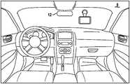
- FIG. 1is a diagram illustrating of a portion of a vehicle
- FIG. 2is a diagram depicting an example system for detecting near-field occlusions on a camera
- FIG. 3is a flowchart depicting an example method for detecting near-field occlusions in images captured by a camera
- FIG. 4is a histogram constructed from intensity values of electromagnetic radiation captured by an image sensor.
- FIG. 5is a flowchart depicting an example method for analyzing electromagnetic radiation intensity.
- FIG. 1illustrates a camera 12 installed in a vehicle 8 .
- the camera 12may be part of a driver assistance system, an autonomous vehicle control system or another vision aided system.
- the camera 12operates to capture images of a scene surrounding the vehicle.
- the images captured by the cameramay be used to detect near-field occlusions on the camera as will be further described below. While the camera 12 is depicted in the context of a vehicle, the techniques for detecting occlusions are applicable to cameras in other applications as well. The technique for detecting occlusions is also applicable to other types of imaging devices.
- FIG. 2depicts a system 20 for detecting near-field occlusions on an exterior lens of a camera 12 .
- the system 20includes a camera 12 and an image processor 22 .
- the camera 12is preferably a color camera. That is, the camera is configured to separate the electromagnetic radiation into two or more mutually distinct frequency bands and capture the electromagnetic radiation in each frequency band with a different image sensor.
- the camerais a Logitech C920 Pro webcam although other types of camera are envisioned by this disclosure.
- the image processor 22is a specialized digital signal processor. It should be understood that the logic for the control of image processor 22 can be implemented in hardware logic, software logic, or a combination of hardware and software logic.
- image processor 22can be or can include any of a digital signal processor (DSP), microprocessor, microcontroller, or other programmable device which are programmed with software implementing the above described methods.
- DSPdigital signal processor
- the controlleris or includes other logic devices, such as a Field Programmable Gate Array (FPGA), a complex programmable logic device (CPLD), or application specific integrated circuit (ASIC).
- FPGAField Programmable Gate Array
- CPLDcomplex programmable logic device
- ASICapplication specific integrated circuit
- the size of all the color imagesare (R, G, B) colors/pixel ⁇ (M rows ⁇ N columns) pixels. M and N could denote all or a portion of a color image.
- An optimal decision Y ⁇ H 0 vs. H 1is one that minimizes E ⁇ C ⁇ .
- This disclosurediscovers a decision process Y ⁇ H 0 vs. H 1 under the most scant a priori information regarding X and W.
- the key to the decision processis that it reduces the high-dimensional decision process Y ⁇ H 0 vs. H 1 into merely a three-dimensional decision process y ⁇ H 0 vs. H 1 as explained in the following paragraphs.
- w[w R , w G , w B ] be an identically distributed (id) random process—an assumption that is most reasonable given that it represents sensor noise.
- x[x R , x G , x B ] be the statistical opposite of w, namely, that x is not an identically distributed random process—an assumption that is most reasonable given that it presents incoming RGB intensity of an arbitrary scene.
- pdfsmarginal probability density functions
- the marginal pdf p y R ( ⁇ )is estimated from the intensity histogram of Y R and similarly the marginal pdf p y G ( ⁇ ) from the intensity histogram of Y G and the marginal pdf p y B ( ⁇ ) from the intensity histogram of Y B .
- FIG. 3further illustrate an example method for detecting near-field occlusions in images captured by a camera.
- the electromagnetic radiation projected by the sceneis separated into two or more mutually distinct frequency bands and each frequency band is captured by a different image sensor of the camera.
- the electromagnetic radiationmay be from the visible spectrum, such that a first image sensor captures electromagnetic radiation in a frequency band corresponding to color red, a second image sensor captures electromagnetic radiation in a frequency band corresponding to color blue, and a third image sensor captures electromagnetic radiation in a frequency band corresponding to color green.
- a first image sensorcaptures electromagnetic radiation in a frequency band corresponding to color red
- a second image sensorcaptures electromagnetic radiation in a frequency band corresponding to color blue
- a third image sensorcaptures electromagnetic radiation in a frequency band corresponding to color green.
- the electromagnetic radiation from the visible spectrumis captured by one image sensor and electromagnetic radiation from the infrared spectrum (outside of the visible spectrum) is captured by another image sensor. Capturing electromagnetic radiation in other frequency bands with other image sensor arrangements is also contemplated by this disclosure.
- Intensity of the electromagnetic radiation forming the imageis analyzed at 32 across the electromagnetic spectrum. More specifically, the intensity of electromagnetic radiation in one frequency band is compared to the intensity of electromagnetic radiation in the other two frequency bands. When the intensity of electromagnetic radiation in the one frequency band is similar to the intensity of electromagnetic radiation in the other two frequency bands, the image is deemed to have a near field occlusion. In this case, the image can be tagged at 34 with an indicator of the occlusion. Other actions for handling occluded images (e.g., discarding occluded images) are also contemplated by this disclosure.
- the intensity of the electromagnetic radiation in each of the frequency bandsis first quantified and then a difference is computed between the quantified intensities for each frequency band.
- the difference in the quantified intensities for the different frequency bandsare less than a predetermined threshold, the image is deemed to have an occlusion.
- a histogramis constructed based on the intensity of the electromagnetic radiation for each pixel of a given image sensor as seen in FIG. 4 .
- Each bin of the histogramrepresents a range of intensity values for electromagnetic radiation.
- the histogramis divided into 50 bins although more or less bins are contemplated by this disclosure.
- each pixel in a given image sensoris first assigned at 51 to one of the plurality of bins defining the histogram based on the intensity value of the corresponding pixel. That is, a histogram is generated from the electromagnetic radiation captured in each of the frequency bands. In this case of a color camera, a histogram is constructed for the red image sensor, a histogram is constructed for the blue image sensor and a histogram is constructed for the green image sensor.
- Pixel counts for corresponding binsare then compared at 53 amongst the different image sensors. For example, pixel count for bin 1 of the histogram for the red image sensor is compared to pixel count for bin 1 of the histogram for the blue image sensor and to the pixel count for bin 1 of the green image sensor. Pixel count for bin 2 of the histogram for the red image sensor is compared to pixel count for bin 2 of the histogram for the blue image sensor and to the pixel count for bin 2 of the green image sensor and so forth.
- the number of bins having the same or substantially the same pixel countare tracked in a bin count.
- the bin countis incremented at 56 if the pixel count for a given bin in one frequency band is the same or substantially the same (e.g., within 5% variance) as the pixel count for the corresponding bin in the other frequency band. If there is more than two sensors, the bin count is incremented only if the pixel counts for all of the sensors are the same or substantially the same. In this way, the bin count indicates how many corresponding bins have substantially the same pixel count.
- Bin countis then compared to a threshold as indicated at 57 .
- a thresholde.g., 80% of the bins
- the intensity of the electromagnetic radiationis similar amongst the image sensors and the image is deemed at 59 to have a near field occlusion.
- the bin countis less than the threshold, the intensity of the electromagnetic radiation differs amongst the image sensors such that the image is deemed at 58 without at occlusion
- the imagecan be divided into a plurality of blocks (e.g., six).
- the blockmay be the same size or different sizes.
- a histogramis constructed for each block in the manner set forth above.
- a determination of similarityis then made for each block in the manner described above. That is, when the bin count for a given block exceeds a predetermined threshold, the intensity of the electromagnetic radiation is similar within the given block.
- an imageis deemed to have a near field occlusion only when the number of similar blocks exceeds a threshold. For example, if five of six blocks are determined to be similar in intensity, then the image is deemed to have a near field occlusion.
- a histogramcan serve as a model in a classifier and images are classified using machine learning.
- a histogramis constructed from the intensity values of the electromagnetic radiation captured by each pixel of a given image sensor, where each bin of the histogram represents a range of intensity values for electromagnetic radiation.
- the histogramincludes sixteen (16) bins for each color (i.e., red, green and blue) for a total of 48 bins.
- Other types of models derived from intensity valuesare also contemplated by this disclosure.
- modelsare constructed for the histogram of a clean image (i.e. no occlusions) as well as histograms for images with different types of debris, such as dirt, dust, ice, snow, rain, fog, etc.
- imagescan be used to train the models. All images for training were selected at random in order to maintain diversity within the training set.
- support vector machinesare used although other types of supervised learning models are contemplated as well.
- a new imageis captured by a camera.
- the histogram of the new imageis then compared by a classifier with the histogram of each of the trained models.
- the classifieroutputs a confidence level. Based on the confidence levels, the new image can be classified as being clean or as having a particular type of occlusion. That is, the new image is classified according to the trained model having the highest confidence level.
- the classifiermay enforce a minimum confidence level. The new image is only classified if at least one of the trained models produces a confidence level which exceeds the minimum confidence level.
- models having different resolutionscan be used to classify images. For example, a first set of models can be constructed based on a histogram with 48 bins, a second set of models can be constructed based on a histogram with 192 bins and a third set of models can be constructed based on a histogram with 768 bins. A new image is then classified using each set of models and tagged with an indicator corresponding to the model produced the highest confidence level.
- the techniques described hereinmay be implemented by one or more computer programs executed by one or more processors.
- the computer programsinclude processor-executable instructions that are stored on a non-transitory tangible computer readable medium.
- the computer programsmay also include stored data.
- Non-limiting examples of the non-transitory tangible computer readable mediumare nonvolatile memory, magnetic storage, and optical storage.
- the present disclosurealso relates to an apparatus for performing the operations herein.
- This apparatusmay be specially constructed for the required purposes, or it may comprise a computer selectively activated or reconfigured by a computer program stored on a computer readable medium that can be accessed by the computer.
- a computer programmay be stored in a tangible computer readable storage medium, such as, but is not limited to, any type of disk including floppy disks, optical disks, CD-ROMs, magnetic-optical disks, read-only memories (ROMs), random access memories (RAMs), EPROMs, EEPROMs, magnetic or optical cards, application specific integrated circuits (ASICs), or any type of media suitable for storing electronic instructions, and each coupled to a computer system bus.
- the computers referred to in the specificationmay include a single processor or may be architectures employing multiple processor designs for increased computing capability.
Landscapes
- Engineering & Computer Science (AREA)
- Multimedia (AREA)
- Signal Processing (AREA)
- Theoretical Computer Science (AREA)
- Quality & Reliability (AREA)
- Computer Vision & Pattern Recognition (AREA)
- Physics & Mathematics (AREA)
- General Physics & Mathematics (AREA)
- Health & Medical Sciences (AREA)
- Biomedical Technology (AREA)
- General Health & Medical Sciences (AREA)
- Human Computer Interaction (AREA)
- Image Analysis (AREA)
- Studio Devices (AREA)
Abstract
Description
Yij=Xij+Wij1≤i≤M,1≤j≤N H1:
Yij=Wij1≤i≤M,1≤j≤N H0:
Claims (14)
Priority Applications (1)
| Application Number | Priority Date | Filing Date | Title |
|---|---|---|---|
| US16/520,780US11145046B2 (en) | 2018-07-24 | 2019-07-24 | Detection of near-field occlusions in images |
Applications Claiming Priority (2)
| Application Number | Priority Date | Filing Date | Title |
|---|---|---|---|
| US201862702408P | 2018-07-24 | 2018-07-24 | |
| US16/520,780US11145046B2 (en) | 2018-07-24 | 2019-07-24 | Detection of near-field occlusions in images |
Publications (2)
| Publication Number | Publication Date |
|---|---|
| US20200034959A1 US20200034959A1 (en) | 2020-01-30 |
| US11145046B2true US11145046B2 (en) | 2021-10-12 |
Family
ID=69179387
Family Applications (1)
| Application Number | Title | Priority Date | Filing Date |
|---|---|---|---|
| US16/520,780ActiveUS11145046B2 (en) | 2018-07-24 | 2019-07-24 | Detection of near-field occlusions in images |
Country Status (1)
| Country | Link |
|---|---|
| US (1) | US11145046B2 (en) |
Cited By (5)
| Publication number | Priority date | Publication date | Assignee | Title |
|---|---|---|---|---|
| US11935978B2 (en) | 2017-09-08 | 2024-03-19 | The Regents Of The University Of Michigan | Electromagnetic energy converter |
| US12323184B2 (en) | 2021-08-30 | 2025-06-03 | The Regents Of The University Of Michigan | Visible light communications technology for inter-vehicular use |
| US12377744B2 (en) | 2018-04-09 | 2025-08-05 | The Regents Of The University Of Michigan | On-demand electric charge service |
| US12431257B2 (en) | 2020-08-03 | 2025-09-30 | The Regents Of The University Of Michigan | Elimination of waveguide modes in organic light-emitting diodes using an ultrathin transparent conductor |
| US12445086B2 (en) | 2021-08-23 | 2025-10-14 | The Regents Of The University Of Michigan | Three-dimensional photovoltaic charging system |
Families Citing this family (9)
| Publication number | Priority date | Publication date | Assignee | Title |
|---|---|---|---|---|
| US11758120B2 (en) | 2020-10-30 | 2023-09-12 | Nvidia Corporation | Evaluating detection capabilities of cameras |
| CN112396125B (en)* | 2020-12-01 | 2022-11-18 | 中国第一汽车股份有限公司 | Classification method, device, equipment and storage medium for positioning test scenes |
| CN113989630B (en)* | 2021-08-31 | 2024-04-23 | 中通服公众信息产业股份有限公司 | Lens shielding judging method based on semantic analysis |
| CN113723318B (en)* | 2021-09-01 | 2024-10-18 | 浙江大华技术股份有限公司 | Method, device and monitoring equipment for determining shielding state of target object |
| CN114332720B (en)* | 2021-12-31 | 2025-04-15 | 上海商汤临港智能科技有限公司 | Camera device occlusion detection method, device, electronic equipment and storage medium |
| CN114387594B (en)* | 2022-01-17 | 2024-04-19 | 中国人民解放军63660部队 | High-frequency electromagnetic scattering shielding identification method |
| CN117011735A (en)* | 2022-04-28 | 2023-11-07 | 中国移动通信集团重庆有限公司 | Occlusion detection method, device, equipment, medium and product of image pickup equipment |
| US20230403449A1 (en)* | 2022-06-14 | 2023-12-14 | Google Llc | Closed loop photography |
| CN116071724B (en)* | 2023-03-03 | 2023-08-04 | 安徽蔚来智驾科技有限公司 | Vehicle-mounted camera occlusion scene recognition method, electronic device, storage medium and vehicle |
Citations (6)
| Publication number | Priority date | Publication date | Assignee | Title |
|---|---|---|---|---|
| US20030193604A1 (en)* | 2002-04-11 | 2003-10-16 | Robins Mark Nelson | Camera lens contamination detection and indication system and method |
| US8619082B1 (en)* | 2012-08-21 | 2013-12-31 | Pelican Imaging Corporation | Systems and methods for parallax detection and correction in images captured using array cameras that contain occlusions using subsets of images to perform depth estimation |
| US8797531B2 (en)* | 2009-05-01 | 2014-08-05 | Xtralis Technologies Ltd | Particle detectors |
| US20160280229A1 (en)* | 2013-12-19 | 2016-09-29 | Ryosuke Kasahara | Object detection apparatus, moving body device control system and program thereof |
| US20180114089A1 (en)* | 2016-10-24 | 2018-04-26 | Fujitsu Ten Limited | Attachable matter detection apparatus and attachable matter detection method |
| US20180114092A1 (en)* | 2016-10-26 | 2018-04-26 | Canon Virginia, Inc. | Devices, systems, and methods for anomaly detection |
Family Cites Families (1)
| Publication number | Priority date | Publication date | Assignee | Title |
|---|---|---|---|---|
| CN101374644B (en)* | 2006-01-30 | 2012-11-07 | 金斯潘控股有限公司 | Phenolic foam board |
- 2019
- 2019-07-24USUS16/520,780patent/US11145046B2/enactiveActive
Patent Citations (6)
| Publication number | Priority date | Publication date | Assignee | Title |
|---|---|---|---|---|
| US20030193604A1 (en)* | 2002-04-11 | 2003-10-16 | Robins Mark Nelson | Camera lens contamination detection and indication system and method |
| US8797531B2 (en)* | 2009-05-01 | 2014-08-05 | Xtralis Technologies Ltd | Particle detectors |
| US8619082B1 (en)* | 2012-08-21 | 2013-12-31 | Pelican Imaging Corporation | Systems and methods for parallax detection and correction in images captured using array cameras that contain occlusions using subsets of images to perform depth estimation |
| US20160280229A1 (en)* | 2013-12-19 | 2016-09-29 | Ryosuke Kasahara | Object detection apparatus, moving body device control system and program thereof |
| US20180114089A1 (en)* | 2016-10-24 | 2018-04-26 | Fujitsu Ten Limited | Attachable matter detection apparatus and attachable matter detection method |
| US20180114092A1 (en)* | 2016-10-26 | 2018-04-26 | Canon Virginia, Inc. | Devices, systems, and methods for anomaly detection |
Non-Patent Citations (12)
| Title |
|---|
| A. Emir Dirik, et al., Source Camera Identification Based on Sensor Dust Characteristics, IEEE, 2007, 6 pages. |
| Bernard Haasdonk & Hans Burkhardt, Invariant Kernel Functions for Pattern Analysis and Machine Learning, Machine Learning, Jul. 2007, vol. 68, Issue 1, pp. 35-61. |
| Bin Liao & Wei Mo, Dirt Detection on Camera Module using Stripe-Wise Background Modeling, Conference Paper, Oct. 2016, 6 pages. |
| Changyin Zhou & Stephen Lin, Removal of Image Artifacts Due to Sensor Dust, IEEE Conference on Computer Vision and Pattern Recognition, Jun. 2007, 8 pages. |
| Chih-Wei Chen & Chiou-Shann Fuh, Lens Shading Correction for Dirt Detection, Pattern Recognition, Machine Intelligence and Biometrics, pp. 171-195 Jan. 2011, 28 pages. |
| Chih-Wei Hsu, et al., A Practical Guide to Support Vector Classification, URL: https://www.csie.ntu.edu.tw/˜cjlin/papers/guide/guide.pdf, 2003, 16 pages. |
| David Eigen, et al., Restoring an Image Taken Through a Window Covered with Dirt or Rain, IEEE International Conference on Computer Vision, Dec. 2013, 8 pages. |
| Dennis Decoste & Bernhard Schölkopf, Training Invariant Support Vector Machines, Machine Learning, Jan. 2002, vol. 46, Issue 1-3, pp. 161-190. |
| Frédérique Crété-Roffet, et al., The Blur Effect: Perception and Estimation with a New No-Reference Perceptual Blur Metric, HAL, Feb. 1, 2008, 12 pages. |
| John R. Smith & Shih-Fu Chang, Tools and Techniques for Color Image Retrieval, IS&T/SPIE Proceedings vol. 2670, Storage & Retrieval for Image and Video Databases IV, Feb. 1996, 10 pages. |
| Kenji Mori, et al., Visibility Estimation in Foggy Conditions by In-Vehicle Camera and Radar, IEEE Computer Society, 2006. |
| Shigeo Abe, On Invariance of Support Vector Machines, URL: http://www2_kobe-u.ac.ip/˜abe/pdf/ideal2003.pdf, Jan. 2003, 8 pages. |
Cited By (5)
| Publication number | Priority date | Publication date | Assignee | Title |
|---|---|---|---|---|
| US11935978B2 (en) | 2017-09-08 | 2024-03-19 | The Regents Of The University Of Michigan | Electromagnetic energy converter |
| US12377744B2 (en) | 2018-04-09 | 2025-08-05 | The Regents Of The University Of Michigan | On-demand electric charge service |
| US12431257B2 (en) | 2020-08-03 | 2025-09-30 | The Regents Of The University Of Michigan | Elimination of waveguide modes in organic light-emitting diodes using an ultrathin transparent conductor |
| US12445086B2 (en) | 2021-08-23 | 2025-10-14 | The Regents Of The University Of Michigan | Three-dimensional photovoltaic charging system |
| US12323184B2 (en) | 2021-08-30 | 2025-06-03 | The Regents Of The University Of Michigan | Visible light communications technology for inter-vehicular use |
Also Published As
| Publication number | Publication date |
|---|---|
| US20200034959A1 (en) | 2020-01-30 |
Similar Documents
| Publication | Publication Date | Title |
|---|---|---|
| US11145046B2 (en) | Detection of near-field occlusions in images | |
| US9922425B2 (en) | Video segmentation method | |
| US7916944B2 (en) | System and method for feature level foreground segmentation | |
| US9514366B2 (en) | Vehicle detection method and system including irrelevant window elimination and/or window score degradation | |
| US9230175B2 (en) | System and method for motion detection in a surveillance video | |
| Faro et al. | Adaptive background modeling integrated with luminosity sensors and occlusion processing for reliable vehicle detection | |
| US8902053B2 (en) | Method and system for lane departure warning | |
| EP1844443B1 (en) | Classifying an object in a video frame | |
| US8305440B2 (en) | Stationary object detection using multi-mode background modelling | |
| US10373320B2 (en) | Method for detecting moving objects in a video having non-stationary background | |
| KR102074073B1 (en) | Method for detecting vehicles and apparatus using the same | |
| KR101735365B1 (en) | The robust object tracking method for environment change and detecting an object of interest in images based on learning | |
| US10970823B2 (en) | System and method for detecting motion anomalies in video | |
| KR101764845B1 (en) | A video surveillance apparatus for removing overlap and tracking multiple moving objects and method thereof | |
| US20080285859A1 (en) | Method and System for Processing Video Data | |
| US10096117B2 (en) | Video segmentation method | |
| EP3255585B1 (en) | Method and apparatus for updating a background model | |
| US11530993B2 (en) | Deposit detection device and deposit detection method | |
| US10726561B2 (en) | Method, device and system for determining whether pixel positions in an image frame belong to a background or a foreground | |
| CN101727570B (en) | Tracking method, detection tracking processing equipment and monitoring system | |
| US20160261808A1 (en) | Information processing apparatus, information processing method, and storage medium | |
| US20140056519A1 (en) | Method, apparatus and system for segmenting an image in an image sequence | |
| EP3726421A2 (en) | Recognition method and apparatus for false detection of an abandoned object and image processing device | |
| Shoaib et al. | Shadow detection for moving humans using gradient-based background subtraction | |
| KR20180074556A (en) | Face detection method and apparatus thereof |
Legal Events
| Date | Code | Title | Description |
|---|---|---|---|
| FEPP | Fee payment procedure | Free format text:ENTITY STATUS SET TO UNDISCOUNTED (ORIGINAL EVENT CODE: BIG.); ENTITY STATUS OF PATENT OWNER: SMALL ENTITY | |
| FEPP | Fee payment procedure | Free format text:ENTITY STATUS SET TO SMALL (ORIGINAL EVENT CODE: SMAL); ENTITY STATUS OF PATENT OWNER: SMALL ENTITY | |
| STPP | Information on status: patent application and granting procedure in general | Free format text:DOCKETED NEW CASE - READY FOR EXAMINATION | |
| STPP | Information on status: patent application and granting procedure in general | Free format text:NON FINAL ACTION MAILED | |
| STPP | Information on status: patent application and granting procedure in general | Free format text:RESPONSE TO NON-FINAL OFFICE ACTION ENTERED AND FORWARDED TO EXAMINER | |
| STPP | Information on status: patent application and granting procedure in general | Free format text:FINAL REJECTION MAILED | |
| STPP | Information on status: patent application and granting procedure in general | Free format text:ADVISORY ACTION MAILED | |
| STPP | Information on status: patent application and granting procedure in general | Free format text:DOCKETED NEW CASE - READY FOR EXAMINATION | |
| STPP | Information on status: patent application and granting procedure in general | Free format text:NOTICE OF ALLOWANCE MAILED -- APPLICATION RECEIVED IN OFFICE OF PUBLICATIONS | |
| AS | Assignment | Owner name:THE REGENTS OF THE UNIVERSITY OF MICHIGAN, MICHIGAN Free format text:ASSIGNMENT OF ASSIGNORS INTEREST;ASSIGNORS:LAKSHMANAN, SRIDHAR;BARGMAN, CHRISTOPHER;SIGNING DATES FROM 20170918 TO 20201120;REEL/FRAME:057272/0648 | |
| STPP | Information on status: patent application and granting procedure in general | Free format text:PUBLICATIONS -- ISSUE FEE PAYMENT RECEIVED | |
| STCF | Information on status: patent grant | Free format text:PATENTED CASE | |
| MAFP | Maintenance fee payment | Free format text:PAYMENT OF MAINTENANCE FEE, 4TH YR, SMALL ENTITY (ORIGINAL EVENT CODE: M2551); ENTITY STATUS OF PATENT OWNER: SMALL ENTITY Year of fee payment:4 |