US11143948B2 - Polarization conversion systems for stereoscopic projection - Google Patents
Polarization conversion systems for stereoscopic projectionDownload PDFInfo
- Publication number
- US11143948B2 US11143948B2US15/933,639US201815933639AUS11143948B2US 11143948 B2US11143948 B2US 11143948B2US 201815933639 AUS201815933639 AUS 201815933639AUS 11143948 B2US11143948 B2US 11143948B2
- Authority
- US
- United States
- Prior art keywords
- image light
- polarization
- conversion system
- polarization conversion
- diverging
- Prior art date
- Legal status (The legal status is an assumption and is not a legal conclusion. Google has not performed a legal analysis and makes no representation as to the accuracy of the status listed.)
- Active
Links
Images


Classifications
- G—PHYSICS
- G02—OPTICS
- G02B—OPTICAL ELEMENTS, SYSTEMS OR APPARATUS
- G02B27/00—Optical systems or apparatus not provided for by any of the groups G02B1/00 - G02B26/00, G02B30/00
- G02B27/28—Optical systems or apparatus not provided for by any of the groups G02B1/00 - G02B26/00, G02B30/00 for polarising
- G02B27/283—Optical systems or apparatus not provided for by any of the groups G02B1/00 - G02B26/00, G02B30/00 for polarising used for beam splitting or combining
- G—PHYSICS
- G02—OPTICS
- G02B—OPTICAL ELEMENTS, SYSTEMS OR APPARATUS
- G02B30/00—Optical systems or apparatus for producing three-dimensional [3D] effects, e.g. stereoscopic images
- G02B30/20—Optical systems or apparatus for producing three-dimensional [3D] effects, e.g. stereoscopic images by providing first and second parallax images to an observer's left and right eyes
- G02B30/22—Optical systems or apparatus for producing three-dimensional [3D] effects, e.g. stereoscopic images by providing first and second parallax images to an observer's left and right eyes of the stereoscopic type
- G02B30/24—Optical systems or apparatus for producing three-dimensional [3D] effects, e.g. stereoscopic images by providing first and second parallax images to an observer's left and right eyes of the stereoscopic type involving temporal multiplexing, e.g. using sequentially activated left and right shutters
- G—PHYSICS
- G02—OPTICS
- G02B—OPTICAL ELEMENTS, SYSTEMS OR APPARATUS
- G02B30/00—Optical systems or apparatus for producing three-dimensional [3D] effects, e.g. stereoscopic images
- G02B30/20—Optical systems or apparatus for producing three-dimensional [3D] effects, e.g. stereoscopic images by providing first and second parallax images to an observer's left and right eyes
- G02B30/22—Optical systems or apparatus for producing three-dimensional [3D] effects, e.g. stereoscopic images by providing first and second parallax images to an observer's left and right eyes of the stereoscopic type
- G02B30/25—Optical systems or apparatus for producing three-dimensional [3D] effects, e.g. stereoscopic images by providing first and second parallax images to an observer's left and right eyes of the stereoscopic type using polarisation techniques
- G—PHYSICS
- G03—PHOTOGRAPHY; CINEMATOGRAPHY; ANALOGOUS TECHNIQUES USING WAVES OTHER THAN OPTICAL WAVES; ELECTROGRAPHY; HOLOGRAPHY
- G03B—APPARATUS OR ARRANGEMENTS FOR TAKING PHOTOGRAPHS OR FOR PROJECTING OR VIEWING THEM; APPARATUS OR ARRANGEMENTS EMPLOYING ANALOGOUS TECHNIQUES USING WAVES OTHER THAN OPTICAL WAVES; ACCESSORIES THEREFOR
- G03B21/00—Projectors or projection-type viewers; Accessories therefor
- G03B21/14—Details
- G03B21/142—Adjusting of projection optics
- G—PHYSICS
- G03—PHOTOGRAPHY; CINEMATOGRAPHY; ANALOGOUS TECHNIQUES USING WAVES OTHER THAN OPTICAL WAVES; ELECTROGRAPHY; HOLOGRAPHY
- G03B—APPARATUS OR ARRANGEMENTS FOR TAKING PHOTOGRAPHS OR FOR PROJECTING OR VIEWING THEM; APPARATUS OR ARRANGEMENTS EMPLOYING ANALOGOUS TECHNIQUES USING WAVES OTHER THAN OPTICAL WAVES; ACCESSORIES THEREFOR
- G03B21/00—Projectors or projection-type viewers; Accessories therefor
- G03B21/14—Details
- G03B21/28—Reflectors in projection beam
- G—PHYSICS
- G03—PHOTOGRAPHY; CINEMATOGRAPHY; ANALOGOUS TECHNIQUES USING WAVES OTHER THAN OPTICAL WAVES; ELECTROGRAPHY; HOLOGRAPHY
- G03B—APPARATUS OR ARRANGEMENTS FOR TAKING PHOTOGRAPHS OR FOR PROJECTING OR VIEWING THEM; APPARATUS OR ARRANGEMENTS EMPLOYING ANALOGOUS TECHNIQUES USING WAVES OTHER THAN OPTICAL WAVES; ACCESSORIES THEREFOR
- G03B35/00—Stereoscopic photography
- G03B35/18—Stereoscopic photography by simultaneous viewing
- G03B35/22—Stereoscopic photography by simultaneous viewing using single projector with stereoscopic-base-defining system
- G—PHYSICS
- G03—PHOTOGRAPHY; CINEMATOGRAPHY; ANALOGOUS TECHNIQUES USING WAVES OTHER THAN OPTICAL WAVES; ELECTROGRAPHY; HOLOGRAPHY
- G03B—APPARATUS OR ARRANGEMENTS FOR TAKING PHOTOGRAPHS OR FOR PROJECTING OR VIEWING THEM; APPARATUS OR ARRANGEMENTS EMPLOYING ANALOGOUS TECHNIQUES USING WAVES OTHER THAN OPTICAL WAVES; ACCESSORIES THEREFOR
- G03B35/00—Stereoscopic photography
- G03B35/18—Stereoscopic photography by simultaneous viewing
- G03B35/26—Stereoscopic photography by simultaneous viewing using polarised or coloured light separating different viewpoint images
- H—ELECTRICITY
- H04—ELECTRIC COMMUNICATION TECHNIQUE
- H04N—PICTORIAL COMMUNICATION, e.g. TELEVISION
- H04N13/00—Stereoscopic video systems; Multi-view video systems; Details thereof
- H04N13/30—Image reproducers
- H04N13/332—Displays for viewing with the aid of special glasses or head-mounted displays [HMD]
- H04N13/341—Displays for viewing with the aid of special glasses or head-mounted displays [HMD] using temporal multiplexing
Definitions
- This disclosurerelates to a projection system for projecting images for a three-dimensional viewing experience, and more in particular to a polarization conversion system utilizing polarized light for encoding stereoscopic images.
- Three-dimensional (3D) imagerycan be synthesized using polarization control following the projector and polarization controlling eyewear (see, e.g., U.S. Pat. No. 4,792,850 to Lipton, which is hereby incorporated by reference herein).
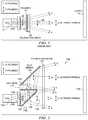
- FIG. 1A conventional implementation of polarization control at the projector is shown in FIG. 1 .
- nearly parallel raysemerge from the output of the lens 10 , appearing to originate from a pupil 12 inside of the lens 10 , and converge to form spots on a screen 14 .
- Ray bundles A, B, and C in FIG. 1are bundles forming spots at the bottom, center, and top of a screen 14 , respectively.
- the light 20 emerging from the projection lensis randomly polarized, depicted in FIG. 1 as both s- and p-polarized light [s-polarized light is conventionally represented as ‘o’; p-polarized light is represented with a double arrow-ended line].
- the light 20passes through a linear polarizer 22 , resulting in a single polarization state after the polarizer 22 .
- the orthogonal polarization stateis absorbed (or reflected), and the light flux after the polarizer 22 is typically less than half of the original flux, thus resulting in a dimmer final image.
- the polarization switch 30is synchronized with the image frame, and the polarization state 24 emerging from the polarization switch is alternated, producing images of alternately orthogonal polarization at the screen.
- Polarization-selective eyewearallows images of one polarization to pass to the left eye, and images of the orthogonal polarization to pass to the right eye. By presenting different images to each eye, 3D imagery can be synthesized.
- This conventional systemhas been used in theatres.
- the conventional systemrequires that greater than 50% of the light is absorbed by the polarizer, and the resulting image is greater than 50% dimmer than that of a typical 2D theatre.
- the dimmer imagecan limit the size of theatre used for 3D applications and/or provides a less desirable viewing experience for the audience.
- the polarization conversion systemspresent a brighter screen image in cinematic applications utilizing polarized light for three-dimensional viewing.
- a polarization conversion systemincludes a polarization beam splitter (PBS), a polarization rotator, and a polarization switch.
- the PBSis operable to receive randomly-polarized light bundles from a projector lens, and direct first light bundles having a first state of polarization (SOP) along a first light path.
- the PBSis also operable to direct second light bundles having a second SOP along a second light path.
- the polarization rotatoris located on the second light path, and is operable to translate the second SOP to the first SOP.
- the polarization switchis operable to receive first and second light bundles from the first and second light paths respectively, and to selectively translate the polarization states of the first and second light bundles to one of a first output SOP and a second output SOP.
- First light bundlesare transmitted toward a projection screen.
- a reflecting elementmay be located in the second light path to direct second light bundles toward a projection screen such that the first and second light bundles substantially overlap to form a brighter screen image.
- a method for stereoscopic image projectionincludes receiving randomly-polarized light from a projector, directing first state of polarization (SOP) light on a first light path, and directing second SOP light on a second light path.
- the methodalso includes transforming the second SOP light on the second light path to first SOP light, and selectively translating the first SOP light on both light paths to one of a first output SOP and a second output SOP.
- SOPstate of polarization
- FIG. 1is a schematic diagram of a conventional polarization switch for stereoscopic projection
- FIG. 2is a schematic diagram of a polarization conversion system (PCS) for cinematic projection in accordance with the present disclosure
- FIG. 3is a schematic diagram of another embodiment of a PCS for cinematic projection in accordance with the present disclosure.
- FIG. 4is a schematic diagram of another embodiment of a PCS for cinematic projection, including a telephoto lens along an optical path and with the field of view centered on the optical axis, in accordance with the present disclosure
- FIG. 5is a schematic diagram of another embodiment of a PCS for cinematic projection, including a telephoto lens along an optical path and with the field of view not centered on the optical axis, in accordance with the present disclosure
- FIG. 6is a schematic diagram of another embodiment of a PCS for cinematic projection to provide a circularly-polarized output, including a telephoto lens along an optical path and with field of view centered on an optical axis, in accordance with the present disclosure
- FIG. 7is a schematic diagram of another embodiment of a PCS for cinematic projection to provide a linearly-polarized output, including a telephoto lens along an optical path and with field of view centered on an optical axis, in accordance with the present disclosure.
- FIG. 8is a schematic diagram of another embodiment of a PCS for cinematic projection in accordance with the present disclosure.
- polarization conversion systemsthat receive light from a projector are described.
- the polarization conversion systemspresent a brighter screen image in cinematic applications utilizing polarized light for three-dimensional viewing.
- FIG. 2is a schematic diagram showing a polarization conversion system (PCS) 100 for cinematic projection.
- An embodiment of the polarization conversion system 100includes a polarizing beam splitter (PBS) 112 , a polarization rotator 114 (e.g., a half-wave plate), a reflecting element 116 (e.g., a fold mirror), and a polarization switch 120 , arranged as shown.
- the polarization conversion system 100may receive images from a conventional projector with a projection lens 122 .
- ray bundles A, B, and Cemerge randomly polarized from the lens 122 and are projected toward a screen 130 to form an image.
- a PBS 112is inserted in place of the polarizer 22 shown in FIG. 1 .
- the PBS 112transmits P-polarized light 124 , and reflects S-polarized light 126 .
- the P-polarized light 124passes through the polarization switch (bundles A, B, and C) and is rotated by the polarization switch in alternating frames, same as bundles A, B, and C in FIG. 1 .
- the S-polarized light 126 reflected by the PBS 112passes through a polarization rotator 114 (e.g., a half-wave plate, preferably achromatic in some embodiments) and is rotated to p-polarized light 128 .
- the new p-polarized light 128passes to a fold mirror 116 .
- the fold mirror 116reflects the new p-polarized light 128 and passes it to polarization switch 120 .
- the polarization switch 120acting on p-polarized ray bundles A′, B′, and C′, rotates the polarization of the ray bundles in alternating frames, in synchronization with the rotation of bundles A, B, and C.
- the position of bundles A′, B′, and C′ at the screenmay be adjusted (e.g., by adjusting the tilt of the fold mirror 116 ) to closely or exactly coincide with the positions of bundles A, B, and C at the screen. Since nearly all of the randomly polarized light 106 from the projection lens 122 is imaged at the screen 130 with a single polarization state, the resulting image of the system in FIG. 2 is approximately two times brighter than the image at the screen for the system in FIG. 1 .
- the PBS 112 in FIG. 2is depicted as a plate.
- the PBS platemay be constructed using a wire grid layer on glass (e.g., Proflux polarizer from Moxtek in Orem, Utah), polarization recycling film (e.g., Double Brightness Enhancing Film from 3M in St. Paul, Minn.), polarization recycling film on glass (for flatness), or a multi-dielectric layer on glass.
- the PBS 112 in FIG. 2could alternatively be implemented as a glass cube (with wire grid, polarization recycling film, or dielectric layers along the diagonal) to reduce astigmatism in the final image associated with light passing through a tilted plate.
- the tilted plate PBS 112 in FIG. 2may, in various embodiments, be implemented with spherical, aspheric, cylindrical or toroidal surfaces to reduce astigmatism in the final image at the screen 130 .
- De-centered spherical, aspheric, cylindrical or toroidal surfaces on the plate, and/or additional de-centered spherical, aspheric, cylindrical or toroidal elements in the optical path after the platecan be implemented to reduce astigmatism in the final image. See, e.g., “Simple method of correcting the aberrations of a beamsplitter in converging light,” V. Doherty and D. Shafer, Proc. SPIE, Vol. 0237, pp. 195-200, 1980, which is hereby incorporated by reference.
- a second flat platemay be inserted into the system after the tilted PBS plate 112 and its tilt adjusted to reduce or correct astigmatism in the final image.
- the polarization rotator 114 in FIG. 2may be an achromatic half-wave plate.
- the half-wave platemay be implemented with polymer films (e.g., Achromatic Retardation Plate from ColorLink, Inc., Boulder, Colo.), quartz plates, or a static liquid crystal device optionally patterned to account for geometric polarization alteration.
- the half-wave plate 114may be positioned as shown in FIG. 2 , or in other embodiments, it may be positioned between the fold mirror 116 and polarization switch 120 , intersecting ray bundles A′, B′, and C′.
- This implementationmay be desirable, as bundles A′, B′, and C′ reflect from the fold mirror 116 in s-polarization state and mirrors often have a higher reflection for s-polarized light.
- the half-wave plate 114should be located such that bundles A′ and C do not overlap at the plate.
- the polarization rotator 114is located in the second light path, it may alternatively be placed in the first light path instead, and the polarization conversion system will operate in a similar manner in accordance with the principles of the present disclosure.
- the fold mirror 116may be replaced with a PBS element (e.g., wire grid plate).
- a purer polarizationmay be maintained after the PBS element.
- Polarization switch 120may be a switch as taught by U.S. Pat. No. 4,792,850; a switch as taught by any of the switches of commonly-assigned U.S. patent application Ser. No. 11/424,087 entitled “Achromatic Polarization Switches”, filed Jun. 14, 2006; both of which are incorporated by reference in their entirety for all purposes, or any other polarization switch known in the art that selectively transforms an incoming state of polarization.
- the polarization switch 120can be split (i.e., to increase yield of the device). If the polarization switch 120 is split, it is desirable that the two devices are located such that there is no overlap of bundles A′ and C in FIG. 2 .
- Splitting the polarization switch 120allows one portion to be relocated in the A′, B′, C′ optical path between the half-wave plate 114 and fold mirror 116 .
- Placing the polarization switch 120 heremay call for the fold mirror 116 to have better polarization preserving properties (e.g., a Silflex coating from Oerlikon in Golden, Colo.) as this may be the last element in the A′, B′, C′ optical path prior to the screen.
- the optical path of ray bundle A′is longer than that of ray bundle A (similarly B′-B and C′-C) resulting in a magnification difference between the images produced by A′, B′, C′ and A, B, C.
- This magnification differencemay be unacceptable to an audience, especially for wide angle and short-throw projection systems.
- Some techniques for correcting this magnification differencemay include (1) providing a curved surface on the fold mirror 116 with optical power that compensates for the magnification difference; this solution is achromatic, which is desirable; (2) adding a fresnel or diffractive surface with optical power to the fold mirror 116 to compensate for the magnification difference (which may or may not be achromatic); (3) adding a refractive element (lens) between the fold mirror 116 and polarization switch 120 , or between the PBS 112 and fold mirror 116 ; a singlet lens is unlikely to be achromatic, but a doublet solution can be achromatic; (4) addition of a telephoto lens as illustrated in FIGS. 3 and 4 ; or (5) a combination of at least two of the above four techniques.
- p-polarized lightis transmitted toward the polarization switch 120 , while s-polarized light is directed toward half-wave plate 114 , it should be apparent to a person of ordinary skill in the art that an alternative configuration may be employed in which s-polarized light is transmitted toward the polarization switch 120 , while p-polarized light is directed toward the half-wave plate 114 .
- FIG. 3is a schematic diagram showing another embodiment of a PCS for cinematic projection 200 .
- the elements of PCS 200may be of similar type and function for those shown with respect to PCS 100 of FIG. 2 .
- elements 2 xxare similar to elements 1 xx , where xx are the last two digits of the respective elements.
- ray bundles A, B, and Cmay be directed through an additional set of fold mirrors 232 , 234 operable to equalize the optical path lengths of bundles A and A′, B and B′, C and C′ as shown in FIG. 3 .
- bundles A′ and C′are present, but not illustrated. They follow a similar path to the A′, B′, C′ bundles shown in FIG. 2 ].
- the PBS and fold mirrorsare shown here to be orientated at 45 degrees to the optical axis, the PBS 212 and fold mirrors 216 , 232 , 236 may have other orientations in accordance with the present teachings.
- glassmay be inserted into the optical path of A′, B′, and C′ (e.g., by replacing the fold mirror 216 with a right angle prism and/or using a glass cube PBS in place of a plate PBS) to reduce or eliminate the optical path difference between the A, B, C and A′, B′, C′ bundles, respectively.
- the image from bundles A′, B′, and C′should substantially overlap the image from bundles A, B, and C for viewing comfort (although perfect overlap is not necessarily required).
- Some techniques of adjusting one image location relative to the otherinclude (1) using thumb screws or a similar mechanical techniques to tilt the fold mirror, PBS plate, or PBS cube; (2) mechanically de-centering a lens or element with optical power (e.g. curved mirror); (3) utilizing a feedback system to automatically adjust image position via one of the aforementioned image adjustment techniques; or (4) a combination of at least two of the above three techniques.
- Optical transmission and stray light controlmay be optimized on optically transmissive elements by providing an anti-reflection coat thereon for high transmission and low reflection. Reflections from transmissive elements can cause stray light in the system which degrades contrast and/or produces disturbing artifacts in the final image.
- additional absorptive polarizersmay be placed after the half-wave plate 114 in the A′, B′, C′ path and/or after the PBS 112 in either path to control polarization leakage and improve the final image contrast.
- FIG. 4is a schematic diagram showing another embodiment of a PCS for cinematic projection 300 .
- the elements of PCS 300may be of similar type and function for those shown with respect to PCS 100 of FIG. 2 .
- elements 3 xxare similar to elements 1 xx , where xx are the last two digits of the respective elements.
- a telephoto lens pair 340may be implemented in the optical path where light transmits through the PBS 312 .
- telephoto lens pair 340is located along an optical path and with the field of view centered on the optical axis.
- telephoto lens 340allows control of magnification, distortion, and imaging properties with two elements such that the two images overlay relatively close, i.e., within 1-4 pixels of each other, while maintaining spots sizes on the order of a fraction of a pixel and lateral color on the order of a pixel.
- a reverse telephoto lensmay be implemented in the optical path where light reflects from the PBS 312 (located between the polarization switch 320 and fold mirror 316 , or after the fold mirror 316 ). If a telephoto or reverse telephoto lens is used for controlling magnification in one optical path, the radial distortion and keystone distortion of the final image can be tuned by laterally displacing the individual elements or pair of elements from the optical axis.
- FIG. 5is a schematic diagram showing another embodiment of a PCS for cinematic projection 400 .
- the elements of PCS 400may be of similar type and function for those shown with respect to PCS 100 of FIG. 2 .
- elements 4 xxare similar to elements 1 xx , where xx are the last two digits of the respective elements.
- a telephoto lens pair 440may be implemented in the optical path where light transmits through the PBS 412 .
- telephoto lens pair 440is located along an optical path and with the field of view decentralized from the optical axis.
- the radial distortion and keystone distortion of the final imagecan be tuned by laterally displacing the individual elements or pair of elements 440 from the optical axis.
- FIG. 6is a schematic diagram of another embodiment of a PCS for cinematic projection 500 that provides a circularly polarized output.
- PCS 500includes a telephoto lens pair 540 along an optical path, with field of view centered on an optical axis.
- each polarization switch 520is a circular polarization switch (or Z-screen), e.g., as described in U.S. Pat. No. 4,792,850.
- the cleanup polarizers 542 , 544 in each pathare optional, depending on the level of contrast desired from the system. For example, including one or both cleanup polarizers may enhance the system contrast.
- FIG. 7is a schematic diagram of another embodiment of a PCS for cinematic projection 600 that provides a linearly polarized output.
- each polarization switch 620is an achromatic linear polarization switch, as described in U.S. patent application Ser. No. 11/424,087 entitled “Achromatic Polarization Switches”, filed Jun. 14, 2006; also manufactured by ColorLink, Inc., of Boulder, Colo.
- cleanup polarizers 642 , 644 in each pathare optional, depending on the level of contrast desired from the system. For example, including one or both cleanup polarizers may enhance the system contrast.
- the achromatic rotator 648is optional, depending on the achromatic properties of the polarization switch 620 .
- FIG. 8is a schematic diagram of another embodiment of a PCS for cinematic projection 700 , showing an alternative configuration in which the polarizers 746 , achromatic rotator 714 , and polarization switches 720 are located after other optical components.
- the elements of PCS 700may be of similar type and function for those shown with respect to PCS 100 of FIG. 2 .
- elements 7 xxare similar to elements 1 xx , where xx are the last two digits of the respective elements.
- P-polarized lightpasses through PBS 712 toward telephoto lens pair 740 , then toward polarization switch 720 .
- An optional cleanup polarizer 746may be located between telephoto lens pair 740 and polarization switch 720 to further enhance contrast.
- the s-polarized light reflected by PBS 712is directed toward fold mirror 716 , where it reflects toward an achromatic rotator 714 that transforms the s-polarized light into p-polarized light, then it passes through an optional cleanup polarizer 746 .
- the p-polarized light from achromatic rotator 714passes through polarization switch 720 .
- the s-polarized light reflected by the PBS 716is efficiently reflected, with polarization maintained by the fold mirror 716 .
- An achromatic 90° rotator 714(probably retarder stack based) can be used to convert light from the fold mirror to the orthogonal state.
- a clean up polarizer 746is likely desirable. This preferably follows the achromatic rotator 714 , thereby reducing polarization conversion efficiency as a factor in system level contrast.
- the final screen imagehas a center located on the optical axis of the projection lens.
- the final screen imagemay be located off-center from the optical axis—for example, a half screen height below the optical axis of the projection lens.
- the polarizing beamsplitter 712may be relocated to intercept the full illumination from the projection lens 722 , and the fold mirror 716 may be tilted to properly overlay the two images on the screen.
- the polarization switch 720 in this embodimenthas been split into two elements (one for each path) to increase fabrication yield; although, as previously discussed, it could alternatively be a single unit.
- the term “cinematic projection”refers to the projection of images using front and/or rear projection techniques, and includes, but is not limited to, applications for cinema, home theatre, simulators, instrumentation, head-up displays, and other projection environments where stereoscopic images are displayed.
Landscapes
- Physics & Mathematics (AREA)
- General Physics & Mathematics (AREA)
- Optics & Photonics (AREA)
- Engineering & Computer Science (AREA)
- Multimedia (AREA)
- Signal Processing (AREA)
- Testing, Inspecting, Measuring Of Stereoscopic Televisions And Televisions (AREA)
- Projection Apparatus (AREA)
- Stereoscopic And Panoramic Photography (AREA)
- Transforming Electric Information Into Light Information (AREA)
- Optical Elements Other Than Lenses (AREA)
- Polarising Elements (AREA)
Abstract
Description
Claims (79)
Priority Applications (1)
| Application Number | Priority Date | Filing Date | Title |
|---|---|---|---|
| US15/933,639US11143948B2 (en) | 2006-09-29 | 2018-03-23 | Polarization conversion systems for stereoscopic projection |
Applications Claiming Priority (9)
| Application Number | Priority Date | Filing Date | Title |
|---|---|---|---|
| US82765706P | 2006-09-29 | 2006-09-29 | |
| US91104307P | 2007-04-10 | 2007-04-10 | |
| US95065207P | 2007-07-19 | 2007-07-19 | |
| US11/864,198US7905602B2 (en) | 2006-09-29 | 2007-09-28 | Polarization conversion systems for stereoscopic projection |
| US13/047,763US8220934B2 (en) | 2006-09-29 | 2011-03-14 | Polarization conversion systems for stereoscopic projection |
| US13/550,182US8833943B2 (en) | 2006-09-29 | 2012-07-16 | Polarization conversion systems for stereoscopic projection |
| US14/485,256US9594298B2 (en) | 2006-09-29 | 2014-09-12 | Polarization conversion systems for stereoscopic projection |
| US14/621,836US9927691B2 (en) | 2006-09-29 | 2015-02-13 | Polarization conversion systems for stereoscopic projection |
| US15/933,639US11143948B2 (en) | 2006-09-29 | 2018-03-23 | Polarization conversion systems for stereoscopic projection |
Related Parent Applications (1)
| Application Number | Title | Priority Date | Filing Date |
|---|---|---|---|
| US14/621,836ContinuationUS9927691B2 (en) | 2006-09-29 | 2015-02-13 | Polarization conversion systems for stereoscopic projection |
Publications (2)
| Publication Number | Publication Date |
|---|---|
| US20190011825A1 US20190011825A1 (en) | 2019-01-10 |
| US11143948B2true US11143948B2 (en) | 2021-10-12 |
Family
ID=39269122
Family Applications (6)
| Application Number | Title | Priority Date | Filing Date |
|---|---|---|---|
| US11/864,198Active2029-05-24US7905602B2 (en) | 2006-09-29 | 2007-09-28 | Polarization conversion systems for stereoscopic projection |
| US13/047,763ActiveUS8220934B2 (en) | 2006-09-29 | 2011-03-14 | Polarization conversion systems for stereoscopic projection |
| US13/550,182Active2027-10-22US8833943B2 (en) | 2006-09-29 | 2012-07-16 | Polarization conversion systems for stereoscopic projection |
| US14/485,256ActiveUS9594298B2 (en) | 2006-09-29 | 2014-09-12 | Polarization conversion systems for stereoscopic projection |
| US14/621,836ActiveUS9927691B2 (en) | 2006-09-29 | 2015-02-13 | Polarization conversion systems for stereoscopic projection |
| US15/933,639ActiveUS11143948B2 (en) | 2006-09-29 | 2018-03-23 | Polarization conversion systems for stereoscopic projection |
Family Applications Before (5)
| Application Number | Title | Priority Date | Filing Date |
|---|---|---|---|
| US11/864,198Active2029-05-24US7905602B2 (en) | 2006-09-29 | 2007-09-28 | Polarization conversion systems for stereoscopic projection |
| US13/047,763ActiveUS8220934B2 (en) | 2006-09-29 | 2011-03-14 | Polarization conversion systems for stereoscopic projection |
| US13/550,182Active2027-10-22US8833943B2 (en) | 2006-09-29 | 2012-07-16 | Polarization conversion systems for stereoscopic projection |
| US14/485,256ActiveUS9594298B2 (en) | 2006-09-29 | 2014-09-12 | Polarization conversion systems for stereoscopic projection |
| US14/621,836ActiveUS9927691B2 (en) | 2006-09-29 | 2015-02-13 | Polarization conversion systems for stereoscopic projection |
Country Status (11)
| Country | Link |
|---|---|
| US (6) | US7905602B2 (en) |
| EP (2) | EP2851735A1 (en) |
| JP (3) | JP5635773B2 (en) |
| KR (4) | KR101625495B1 (en) |
| DE (1) | DE202007019714U1 (en) |
| DK (1) | DK2067066T3 (en) |
| ES (1) | ES2528489T3 (en) |
| PL (1) | PL2067066T3 (en) |
| PT (1) | PT2067066E (en) |
| SI (1) | SI2067066T1 (en) |
| WO (1) | WO2008042798A2 (en) |
Cited By (1)
| Publication number | Priority date | Publication date | Assignee | Title |
|---|---|---|---|---|
| TWI857594B (en)* | 2023-05-01 | 2024-10-01 | 友達光電股份有限公司 | Switchable optical imaging device, processing system, and method, the optical imaging processing system |
Families Citing this family (78)
| Publication number | Priority date | Publication date | Assignee | Title |
|---|---|---|---|---|
| JP5635773B2 (en) | 2006-09-29 | 2014-12-03 | リアルディー インコーポレイテッドRealD Inc. | Polarization conversion system for stereoscopic projection, projection system, and stereoscopic image projection method |
| US7857455B2 (en) | 2006-10-18 | 2010-12-28 | Reald Inc. | Combining P and S rays for bright stereoscopic projection |
| US8727536B2 (en) | 2007-05-09 | 2014-05-20 | Reald Inc. | Polarization conversion system and method for projecting polarization encoded imagery |
| US9244287B2 (en) | 2008-05-09 | 2016-01-26 | Reald Inc. | Optical systems with compact back focal lengths |
| JP5381371B2 (en)* | 2008-11-07 | 2014-01-08 | 株式会社リコー | Polarization separation device, optical scanning device, and image forming apparatus |
| JP5434085B2 (en)* | 2009-01-16 | 2014-03-05 | ソニー株式会社 | Projection-type image display device and projection optical system |
| JP5332961B2 (en)* | 2009-06-30 | 2013-11-06 | セイコーエプソン株式会社 | Electro-optical device and electronic apparatus |
| US8220931B2 (en)* | 2009-07-07 | 2012-07-17 | Eastman Kodak Company | Etendue reduced stereo projection using segmented disk |
| US10678061B2 (en)* | 2009-09-03 | 2020-06-09 | Laser Light Engines, Inc. | Low etendue illumination |
| US8328362B2 (en) | 2010-02-24 | 2012-12-11 | Reald Inc. | Waveplate compensation in projection polarization conversion system |
| JP5402791B2 (en)* | 2010-04-02 | 2014-01-29 | セイコーエプソン株式会社 | projector |
| TWI435117B (en) | 2010-09-07 | 2014-04-21 | Delta Electronics Inc | Polarization conversion system and stereoscopic projection system employing same |
| EP2720089B1 (en)* | 2010-09-08 | 2018-08-15 | Dai Nippon Printing Co., Ltd. | Illumination device, projection device, and projection-type image display device |
| CN102692724A (en)* | 2011-03-23 | 2012-09-26 | 深圳市亿思达显示科技有限公司 | Projector and stereoscopic image system |
| CN102591128B (en)* | 2011-03-30 | 2014-05-14 | 深圳市亿思达显示科技有限公司 | Projector and stereo image system |
| US9110368B2 (en)* | 2011-06-16 | 2015-08-18 | Reald Inc. | Anamorphic stereoscopic optical apparatus and related methods |
| FR2978564B1 (en)* | 2011-07-29 | 2013-08-23 | Volfoni R & D | DEVICE FOR POLARIZING A VIDEO SEQUENCE TO BE VIEWED IN STEREOSCOPY |
| EP2780756A4 (en)* | 2011-11-15 | 2015-05-27 | Elbit Systems America Llc | SYSTEM AND METHOD FOR STREAMING MULTIPLE PICTURES FROM A SINGLE PROJECTOR |
| US8651678B2 (en)* | 2011-11-29 | 2014-02-18 | Massachusetts Institute Of Technology | Polarization fields for dynamic light field display |
| KR101916719B1 (en)* | 2012-04-10 | 2019-01-30 | 엘지전자 주식회사 | Image projection apparatus |
| US10477194B2 (en) | 2012-04-25 | 2019-11-12 | 3M Innovative Properties Company | Two imager projection device |
| CN103728821B (en)* | 2012-10-12 | 2015-10-28 | 扬明光学股份有限公司 | projection device |
| CN103869594A (en)* | 2012-12-17 | 2014-06-18 | 上海蝶维影像科技有限公司 | 3D (three-dimensional) conversion device and 3D conversion system |
| KR101387096B1 (en)* | 2013-02-04 | 2014-04-18 | 유한회사 마스터이미지쓰리디아시아 | A stereoscopic projection having multi beam splititing device |
| US9494805B2 (en) | 2013-03-26 | 2016-11-15 | Lightspeed Design, Inc. | Stereoscopic light recycling device |
| KR101387097B1 (en) | 2013-04-02 | 2014-04-29 | 유한회사 마스터이미지쓰리디아시아 | Three beam splitting method and a stereoscopic projection using the same |
| CN104330953A (en)* | 2013-07-22 | 2015-02-04 | 深圳市亿思达科技集团有限公司 | 3D projection system and control method thereof |
| JP6327806B2 (en)* | 2013-08-02 | 2018-05-23 | 国立研究開発法人情報通信研究機構 | Display device |
| KR101419448B1 (en) | 2013-09-05 | 2014-07-17 | 유한회사 마스터이미지쓰리디아시아 | Four beam splitting method and A stereoscopic projection using the same |
| WO2015073838A1 (en) | 2013-11-15 | 2015-05-21 | Reald Inc. | High dynamic range, high contrast projection systems |
| CN103616772B (en)* | 2013-11-27 | 2016-08-24 | 王高胜 | 3D video system and 3D projecting method |
| KR101574285B1 (en) | 2013-12-16 | 2015-12-03 | 유한회사 마스터이미지쓰리디아시아 | A stereoscopic image projection device for improved brightness and a providing method for A stereoscopic image |
| CN106164751A (en)* | 2014-03-04 | 2016-11-23 | 斯特立体影像科技有限公司 | Modulator for stereoscopic image device and stereoscopic image device using the modulator |
| CN203732876U (en)* | 2014-03-11 | 2014-07-23 | 刘飞 | Optical system used for stereoscopic projection |
| TWI538477B (en)* | 2014-03-24 | 2016-06-11 | 台達電子工業股份有限公司 | Autostereoscopic display device |
| AU2015335897B2 (en) | 2014-10-21 | 2021-04-22 | Reald Inc. | High power handling polarization switches |
| US10082675B2 (en) | 2014-10-21 | 2018-09-25 | Reald Inc. | High power handling polarization switches |
| TWI553392B (en) | 2015-01-06 | 2016-10-11 | 台達電子工業股份有限公司 | Polarized projection device and polarized projection system using the same |
| US9904162B2 (en) | 2015-03-02 | 2018-02-27 | Reald Inc. | Multiple projector imaging system |
| KR101702024B1 (en)* | 2015-04-06 | 2017-02-02 | 유한회사 마스터이미지쓰리디아시아 | Stereoscopic Image Display Apparatus with Remote Controlled Alignment Function and Method for Displaying Stereoscopic Image Using the Same |
| US10097800B2 (en) | 2015-05-11 | 2018-10-09 | Reald Inc. | Optical lens systems with dynamic iris for modulating image frames |
| KR101675436B1 (en)* | 2015-05-18 | 2016-11-14 | 유한회사 마스터이미지쓰리디아시아 | Stereoscopic Projection Device Reducing Crosstalk |
| CN107613842B (en)* | 2015-05-29 | 2019-09-24 | 奥林巴斯株式会社 | Lighting device and measuring device |
| US9594255B2 (en) | 2015-06-25 | 2017-03-14 | Volfoni R&D EURL | Stereoscopic 3D projection system with improved level of optical light efficiency |
| WO2017040530A1 (en) | 2015-08-31 | 2017-03-09 | Reald Inc. | High dynamic range projection with multiple numerical aperture illumination |
| WO2017083526A1 (en)* | 2015-11-10 | 2017-05-18 | Reald Inc. | Distortion matching polarization conversion systems and methods thereof |
| WO2017091538A1 (en)* | 2015-11-23 | 2017-06-01 | University Of Central Florida Research Foundation, Inc. | Optical system, method, and applications |
| CN110140352B (en) | 2016-01-26 | 2021-07-27 | 图象公司 | Stereoscopic image projection with high intra-frame contrast |
| TWI604225B (en)* | 2016-02-05 | 2017-11-01 | 尚立光電股份有限公司 | Optical arrangement of head up display |
| KR101641479B1 (en) | 2016-03-24 | 2016-07-20 | 김상수 | Apparatus for displaying a stereoscopic image |
| WO2018070826A1 (en)* | 2016-10-13 | 2018-04-19 | 주식회사 엘지화학 | Optical isolation apparatus |
| CN108073030B (en)* | 2016-11-09 | 2023-08-29 | 深圳光峰科技股份有限公司 | A kind of 3D projection lens and projection equipment |
| US10095097B2 (en) | 2016-11-29 | 2018-10-09 | Hyundai Motor Company | Projection-type optical module |
| KR20180092054A (en)* | 2017-02-08 | 2018-08-17 | 유 킴 훙 | Providing 3-dimensional image |
| JP7263643B2 (en) | 2017-03-08 | 2023-04-25 | メタ プラットフォームズ テクノロジーズ, リミテッド ライアビリティ カンパニー | Wide angle variable neutral density filter |
| CN110730924A (en)* | 2017-04-06 | 2020-01-24 | Lg电子株式会社 | Head-up display device for vehicle |
| CN111108428A (en) | 2017-07-17 | 2020-05-05 | 加里夏普创新有限责任公司 | Wide angle compensation of uniaxial retarder stacks |
| WO2019035494A1 (en)* | 2017-08-16 | 2019-02-21 | 주식회사 시네마이스터 | Split-in-two digital cinema displaying method and apparatus |
| WO2019035495A1 (en)* | 2017-08-16 | 2019-02-21 | 주식회사 시네마이스터 | Split-in-three digital cinema displaying method and apparatus |
| US10151932B1 (en) | 2017-09-01 | 2018-12-11 | Volfoni R&D | Stereoscopic three dimensional projection system using elliptical polarization |
| US10459240B2 (en) | 2017-10-11 | 2019-10-29 | Volfoni R&D | Stereoscopic three dimensional projection system with short throw ratio |
| US11889234B2 (en) | 2017-11-14 | 2024-01-30 | Imax Theatres International Limited | Light conditioning of direct view display for cinema |
| KR101970898B1 (en)* | 2017-11-23 | 2019-04-19 | 킴 훙 유 | Image Conversion Based On Multiple Polarization Rotators |
| CN110300914B (en) | 2018-01-12 | 2021-10-19 | Jvc建伍株式会社 | virtual image display device |
| JP6593465B2 (en)* | 2018-01-12 | 2019-10-23 | 株式会社Jvcケンウッド | Virtual image display device |
| JP6593464B2 (en) | 2018-01-12 | 2019-10-23 | 株式会社Jvcケンウッド | Virtual image display device |
| JP6593461B2 (en)* | 2018-01-12 | 2019-10-23 | 株式会社Jvcケンウッド | Virtual image display device |
| US11249355B2 (en) | 2018-01-29 | 2022-02-15 | Gary Sharp Innovations, Llc | Color switch for reduced color cross-talk |
| EP3746822A4 (en) | 2018-01-29 | 2022-01-12 | Gary Sharp Innovations, LLC | Hollow triple-pass optical elements |
| US11320665B2 (en) | 2018-03-02 | 2022-05-03 | Gary Sharp Innovatnons, Llc | Retarder stack pairs for polarization basis vector transformations |
| CN109188700B (en)* | 2018-10-30 | 2021-05-11 | 京东方科技集团股份有限公司 | Optical display system and AR/VR display device |
| WO2020185259A1 (en) | 2019-03-08 | 2020-09-17 | Reald Inc. | Polarizing beam splitter assembly with diffracting element |
| JP2022526184A (en)* | 2019-04-11 | 2022-05-23 | ゲイリー シャープ イノベーションズ リミテッド ライアビリティ カンパニー | Polarization compensator for inclined surfaces |
| JP7240977B2 (en)* | 2019-07-10 | 2023-03-16 | 日本放送協会 | image display device |
| US11531212B2 (en) | 2019-11-21 | 2022-12-20 | Volfoni R&D | Stereoscopic 3D system using linear polarization |
| WO2021144599A1 (en) | 2020-01-14 | 2021-07-22 | Volfoni R&D | High brightness stereoscopic 3d projection system |
| JP7481222B2 (en)* | 2020-09-30 | 2024-05-10 | 株式会社Nttドコモ | Image projection system and screen |
| US20240372978A1 (en)* | 2021-08-20 | 2024-11-07 | Sony Group Corporation | Display apparatus and display method |
Citations (136)
| Publication number | Priority date | Publication date | Assignee | Title |
|---|---|---|---|---|
| US2403731A (en) | 1943-04-01 | 1946-07-09 | Eastman Kodak Co | Beam splitter |
| US3208337A (en) | 1963-04-15 | 1965-09-28 | Minnesota Mining & Mfg | Stand for an overhead projector |
| US3704997A (en) | 1971-05-19 | 1972-12-05 | American Optical Corp | Variable amplitude polarizing beam splitter |
| JPS5635773B2 (en) | 1976-12-27 | 1981-08-19 | ||
| JPS5641424B2 (en) | 1974-11-30 | 1981-09-28 | ||
| US4515441A (en) | 1982-10-13 | 1985-05-07 | Westinghouse Electric Corp. | Dielectric polarizer for high average and high peak power operation |
| SU1182471A1 (en) | 1983-05-19 | 1985-09-30 | Киевский Ордена Ленина Политехнический Институт Им.50-Летия Великой Октябрьской Социалистической Революции | Stereoscopic projecting device |
| JPS6211823A (en) | 1985-07-10 | 1987-01-20 | Mitsubishi Electric Corp | polarization converter |
| US4719507A (en) | 1985-04-26 | 1988-01-12 | Tektronix, Inc. | Stereoscopic imaging system with passive viewing apparatus |
| US4792850A (en) | 1987-11-25 | 1988-12-20 | Sterographics Corporation | Method and system employing a push-pull liquid crystal modulator |
| EP0349692A2 (en) | 1988-07-05 | 1990-01-10 | KAISER AEROSPACE & ELECTRONICS CORPORATION | Stereoscopic display |
| JPH0463305A (en) | 1990-07-03 | 1992-02-28 | Konica Corp | Polarizing beam splitter and laser interferometer |
| US5164854A (en) | 1990-07-27 | 1992-11-17 | Victor Company Of Japan, Ltd. | Polarization converter for converting unpolarized light to linearly polarized light |
| JPH0573116A (en) | 1991-09-13 | 1993-03-26 | Fuji Electric Co Ltd | Program controller |
| JPH05127120A (en) | 1991-11-05 | 1993-05-25 | Sharp Corp | Stereoscopic display system |
| US5225861A (en) | 1991-01-18 | 1993-07-06 | Mortimer Marks | Apparatus for projection of three-dimensional images |
| JPH05203894A (en) | 1992-01-27 | 1993-08-13 | Fujitsu General Ltd | Display device using light valve |
| JPH05241103A (en) | 1992-02-21 | 1993-09-21 | Nec Corp | Projection type liquid crystal display device |
| US5278680A (en) | 1989-10-05 | 1994-01-11 | Seiko Epson Corporation | Projection type liquid crystal display system and method of polarized light component projection |
| JPH06289387A (en) | 1993-04-05 | 1994-10-18 | Seiko Epson Corp | Illumination optical system and projection display device |
| US5359455A (en) | 1989-12-26 | 1994-10-25 | Mitsubishi Rayon Co., Ltd. | Polarization forming optical device |
| JPH06317760A (en) | 1993-05-10 | 1994-11-15 | Seiko Epson Corp | Display device |
| US5381278A (en) | 1991-05-07 | 1995-01-10 | Canon Kabushiki Kaisha | Polarization conversion unit, polarization illumination apparatus provided with the unit, and projector provided with the apparatus |
| JPH0756167A (en) | 1993-08-18 | 1995-03-03 | Nec Corp | Polarization light source and projection type liquid crystal display device using the same |
| JPH0764075A (en) | 1993-08-25 | 1995-03-10 | Nec Corp | Liquid crystal projection device |
| JPH07146474A (en) | 1993-11-22 | 1995-06-06 | Nec Corp | Polarization converting optical system of projection type liquid crystal display device |
| US5435859A (en) | 1992-08-06 | 1995-07-25 | Erd Corporation | Method of producing a rare earth bond magnet |
| JPH0772428B2 (en) | 1989-04-17 | 1995-08-02 | 松下電器産業株式会社 | Retractable toilet unit |
| JPH07239473A (en) | 1994-02-28 | 1995-09-12 | Nec Corp | Projection type liquid crystal display device |
| US5453859A (en) | 1993-06-03 | 1995-09-26 | Matsushita Electric Industrial Co., Ltd. | Polarization beam splitter and projection display apparatus |
| JPH07333557A (en) | 1994-06-09 | 1995-12-22 | Sony Corp | Image projection device |
| US5481321A (en) | 1991-01-29 | 1996-01-02 | Stereographics Corp. | Stereoscopic motion picture projection system |
| US5497270A (en) | 1994-07-13 | 1996-03-05 | Kaiser Aerospace & Electronics Corporation | Apparatus and method for increasing resolution and expanding the displayed field of view |
| JP2538127B2 (en) | 1990-11-30 | 1996-09-25 | 松下電器産業株式会社 | Liquid crystal projection type television and liquid crystal projection type color television using the same |
| US5566367A (en) | 1991-04-09 | 1996-10-15 | Canon Kabushiki Kaisha | Plate-like polarizing element, a polarizing conversion unit provided with the element, and a projector provided with the unit |
| JPH08317428A (en) | 1995-05-22 | 1996-11-29 | Nec Corp | Liquid crystal projector |
| JPH0926555A (en) | 1995-07-12 | 1997-01-28 | Sanyo Electric Co Ltd | Stereoscopic image display device |
| JPH09120047A (en) | 1995-10-25 | 1997-05-06 | Nec Corp | Video projector |
| US5691785A (en) | 1990-09-18 | 1997-11-25 | Mitsubishi Denki Kabushiki Kaisha | Color projection type display apparatus having three liquid displays of same structure |
| US5729306A (en) | 1994-09-30 | 1998-03-17 | Sharp Kabushiki Kaisha | Light splitting and synthesizing device and liquid crystal display apparatus including the same |
| US5772299A (en) | 1994-11-25 | 1998-06-30 | Lg Electronics Inc. | Optical apparatus for liquid crystal display projector |
| US5822129A (en) | 1995-11-07 | 1998-10-13 | Nikon Corporation | Projection lens system |
| US5822128A (en) | 1996-03-22 | 1998-10-13 | Nikon Corporation | Projection lenses for display elements and projection systems comprising same |
| US5917568A (en) | 1994-07-08 | 1999-06-29 | The Regents Of The University Of Colorado | Adaptive attenuating spatial light modulator |
| US5917562A (en) | 1994-12-16 | 1999-06-29 | Sharp Kabushiki Kaisha | Autostereoscopic display and spatial light modulator |
| JPH11260141A (en) | 1998-03-11 | 1999-09-24 | Omron Corp | Polarization converting optical element and linear polarization rotating method |
| US5982538A (en) | 1994-01-28 | 1999-11-09 | Mitsubishi Denki Kabushiki Kaisha | Stereoscopic image projection apparatus and telecentric zoom lens |
| US5993004A (en) | 1996-09-19 | 1999-11-30 | Sharp Kabushiki Kaisha | Display |
| EP0961237A2 (en) | 1998-04-23 | 1999-12-01 | Pitney Bowes Inc. | Mailing machine including an embedded control system having a screen control architecture |
| US6067193A (en) | 1997-10-15 | 2000-05-23 | Nikon Corporation | Polarization device and projection type display apparatus |
| US6094240A (en) | 1996-09-04 | 2000-07-25 | Hitachi, Ltd. | Liquid crystal display polarizing beam splitter with specific incidence angle |
| US6122103A (en) | 1999-06-22 | 2000-09-19 | Moxtech | Broadband wire grid polarizer for the visible spectrum |
| US6147802A (en) | 1994-12-28 | 2000-11-14 | Seiko Epson Corporation | Polarization luminaire and projection display |
| US6154320A (en) | 1997-06-06 | 2000-11-28 | Seiko Epson Corporation | Polarizing conversion device, polarizing illuminations device, and display apparatus and projector using the devices |
| WO2000078056A1 (en) | 1999-06-14 | 2000-12-21 | Vega Medien Aktiengesellschaft | Projection device and projection method for carrying out simulated three-dimensional reproduction |
| US6190013B1 (en) | 1997-07-03 | 2001-02-20 | Minolta Co., Ltd. | Polarized beam splitter and an illumination optical system and a projector provided with a polarized beam splitter |
| US6206532B1 (en) | 1996-10-17 | 2001-03-27 | New Exciting Designs Limited | High efficiency light source projection apparatus |
| US6243199B1 (en) | 1999-09-07 | 2001-06-05 | Moxtek | Broad band wire grid polarizing beam splitter for use in the visible wavelength region |
| US6252624B1 (en) | 1997-07-18 | 2001-06-26 | Idemitsu Kosan Co., Ltd. | Three dimensional display |
| US20010013971A1 (en) | 1996-10-16 | 2001-08-16 | Paul Kleinberger | Systems for three-dimensional viewing and projection |
| US6280034B1 (en) | 1999-07-30 | 2001-08-28 | Philips Electronics North America Corporation | Efficient two-panel projection system employing complementary illumination |
| US6288840B1 (en) | 1999-06-22 | 2001-09-11 | Moxtek | Imbedded wire grid polarizer for the visible spectrum |
| US6375327B2 (en) | 1996-09-30 | 2002-04-23 | Digital Optics Internat | Image projection system |
| US6437915B2 (en) | 1996-09-12 | 2002-08-20 | Sharp Kabushiki Kaisha | Parallax barrier, display, passive polarization modulating optical element and method of making such an element |
| US6454416B2 (en) | 2000-05-11 | 2002-09-24 | Hitachi, Ltd. | Color liquid crystal projector having an improved optical system |
| JP2002287092A (en) | 2000-12-23 | 2002-10-03 | Carl Zeiss:Fa | Stereoscopic display device |
| US6508557B1 (en) | 2000-06-28 | 2003-01-21 | Koninklijke Philips Electronics N.V. | Reflective LCD projector |
| US6547396B1 (en) | 2001-12-27 | 2003-04-15 | Infocus Corporation | Stereographic projection system |
| US6582080B2 (en) | 1999-07-19 | 2003-06-24 | Imax Corporation | Image projection system |
| US20030128320A1 (en) | 2002-01-07 | 2003-07-10 | Eastman Kodak Company | Display apparatus using a wire grid polarizing beamsplitter with compensator |
| US6631992B2 (en) | 2001-03-30 | 2003-10-14 | Koninklijke Philips Electronics N.V. | Projector color correction to target white points |
| US6636276B1 (en) | 1999-09-09 | 2003-10-21 | International Business Machines Corporation | Projection display system with at least two reflective light valves |
| US6704065B1 (en) | 1995-04-07 | 2004-03-09 | Colorlink, Inc. | Optical system for producing a modulated color image |
| US20040090601A1 (en) | 2002-11-07 | 2004-05-13 | Nec Viewtechnology, Ltd. | Liquid crystal projector |
| JP2004138433A (en) | 2002-10-16 | 2004-05-13 | Ishikawa Pref Gov | Laser interferometer and measuring device using the same |
| US6761459B1 (en) | 1999-07-08 | 2004-07-13 | Svyatoslav Ivanovich Arsenich | Projection system |
| US6801263B2 (en) | 2000-04-10 | 2004-10-05 | Sony Corporation | Liquid crystal display, liquid crystal device and liquid crystal display system |
| US20040246586A1 (en) | 2003-03-20 | 2004-12-09 | Samsung Electronics Co., Ltd. | Illumination system providing light of Gaussian distribution, projection system, and method of forming color image |
| US20040263806A1 (en) | 2002-06-05 | 2004-12-30 | Eastman Kodak Company | Housing for mounting a beamsplitter and a spatial light modulator with an output optical path |
| US6839095B2 (en) | 2002-05-17 | 2005-01-04 | Infocus Corporation | Single-path color video projection systems employing reflective liquid crystal display devices |
| US20050017938A1 (en) | 2002-01-28 | 2005-01-27 | O'donnell Eugene Murphy | Stereoscopic light engine architecture |
| US20050030749A1 (en) | 2003-05-26 | 2005-02-10 | Seiko Epson Corporation | Illumination device and projector |
| JP2005512118A (en) | 2001-11-30 | 2005-04-28 | カラーリンク・インコーポレイテッド | Compensated color management system and method |
| US6912074B1 (en) | 2004-08-04 | 2005-06-28 | Industry-University Cooperation Foundation Hanyang University | Method of producing a big size holographic projection screen for displaying a three-dimensional color images without color deterioration |
| US20050157233A1 (en) | 2004-01-16 | 2005-07-21 | Meng-Chai Wu | Optical converter module for display system |
| WO2005069058A1 (en) | 2004-01-09 | 2005-07-28 | Koninklijke Philips Electronics N.V. | Optical path length adjuster |
| US20050185139A1 (en) | 2004-02-25 | 2005-08-25 | Olympus Corporation | Light modulating unit and image projection apparatus |
| US6976759B2 (en) | 2002-02-28 | 2005-12-20 | 3M Innovative Properties Company | Compound polarization beam splitters |
| US20060007537A1 (en) | 1992-06-11 | 2006-01-12 | Sedlmayr Steven R | High efficiency electromagnetic beam projector, and systems and methods for implementation thereof |
| US20060044516A1 (en) | 2004-08-31 | 2006-03-02 | Canon Kabushiki Kaisha | Image display apparatus |
| WO2006038744A1 (en) | 2004-10-07 | 2006-04-13 | Dong-Yoon Kim | Digital image projection system and method for 3-dimensional stereoscopic display |
| US20060092380A1 (en) | 2004-11-04 | 2006-05-04 | Salsman Kenneth E | Clean-up polarizer and gamma control for display system |
| JP2006133601A (en) | 2004-11-08 | 2006-05-25 | Nec Viewtechnology Ltd | Light source and liquid crystal projector |
| JP2006227361A (en) | 2005-02-18 | 2006-08-31 | Seiko Epson Corp | Polarization conversion optical element, illumination device, and projector |
| US20060215118A1 (en) | 2005-03-25 | 2006-09-28 | Seiko Epson Corporation | Image display device |
| US20060221429A1 (en) | 2005-03-31 | 2006-10-05 | Evans & Sutherland Computer Corporation | Reduction of speckle and interference patterns for laser projectors |
| US20060250581A1 (en) | 2005-05-03 | 2006-11-09 | Eastman Kodak Company | Display apparatus using LCD panel |
| US20060291053A1 (en) | 2006-01-23 | 2006-12-28 | Colorlink, Inc. | Achromatic Polarization Switches |
| DE20023883U1 (en) | 2000-12-23 | 2007-03-15 | Carl Zeiss Ag | Stereoscopic display system e.g. head mounted display system, for use in TV-monitor, has switch which separately couples represented image information from common part of observation optical path to respective separate optical paths |
| US7198373B2 (en) | 2005-05-03 | 2007-04-03 | Eastman Kodak Company | Display apparatus using LCD panel |
| US7224411B2 (en) | 2000-03-31 | 2007-05-29 | Imax Corporation | Digital projection equipment and techniques |
| CN101021674A (en) | 2006-02-13 | 2007-08-22 | 深圳雅图数字视频技术有限公司 | LCD stereo projector polarization management system |
| US7261453B2 (en) | 2005-01-25 | 2007-08-28 | Morejon Israel J | LED polarizing optics for color illumination system and method of using same |
| US20070279595A1 (en) | 2006-06-02 | 2007-12-06 | 3M Innovative Properties Company | Illumination system and projection system using same |
| JP2008074479A (en) | 2006-09-25 | 2008-04-03 | Kao Corp | Refill bag |
| WO2008042798A2 (en) | 2006-09-29 | 2008-04-10 | Colorlink, Inc. | Polarization conversion systems for stereoscopic projection |
| US7387388B2 (en) | 2004-04-15 | 2008-06-17 | Jds Uniphase Corporation | Illumination system using polarization conversion |
| US20080143965A1 (en) | 2006-10-18 | 2008-06-19 | Real D | Combining P and S rays for bright stereoscopic projection |
| US20080143964A1 (en) | 2006-10-18 | 2008-06-19 | Real D | Dual ZScreen® projection |
| KR20090008932A (en) | 2007-07-19 | 2009-01-22 | 주식회사 뉴파워 프라즈마 | Plasma Reactor with Multi-Core Plasma Generating Plate |
| CN101408675A (en) | 2007-10-09 | 2009-04-15 | 鸿富锦精密工业(深圳)有限公司 | Stereo projection optical system |
| US20090128780A1 (en) | 2007-05-09 | 2009-05-21 | Real D | Polarization conversion system and method for stereoscopic projection |
| US7559653B2 (en) | 2005-12-14 | 2009-07-14 | Eastman Kodak Company | Stereoscopic display apparatus using LCD panel |
| JP2010072138A (en) | 2008-09-17 | 2010-04-02 | Nikon Corp | Illumination optical system and projector device using the same |
| DE102008043153A1 (en) | 2008-10-24 | 2010-04-29 | Robert Bosch Gmbh | Method for creating an image as well as projector and mobile phone with a projector |
| JP2010122589A (en) | 2008-11-21 | 2010-06-03 | Sony Corp | Stereoscopic image display, polarized light splitting and synthesizing device, and stereoscopic image display method |
| US20100141856A1 (en) | 2008-12-01 | 2010-06-10 | Real D | Stereoscopic projection systems for employing spatial multiplexing at an intermediate image plane |
| US7753531B2 (en) | 2004-05-13 | 2010-07-13 | Ricoh Company, Ltd. | Image display apparatus and projection optical system |
| JP2010164802A (en) | 2009-01-16 | 2010-07-29 | Sony Corp | Projection type image display device and projection optical system |
| JP2010276710A (en) | 2009-05-26 | 2010-12-09 | Institute Of National Colleges Of Technology Japan | Stereoscopic image projection apparatus and method |
| US20100328561A1 (en) | 2009-06-29 | 2010-12-30 | Reald Inc. | Stereoscopic projection system employing spatial multiplexing at an intermediate image plane |
| US7887193B2 (en) | 2005-07-15 | 2011-02-15 | Sanyo Electric Co., Ltd. | Illuminating device and projection type video display apparatus |
| KR20120009141A (en) | 2010-07-22 | 2012-02-01 | 주식회사 포스코 | High-strength coal briquette manufacturing system and its manufacturing method |
| US20120057134A1 (en) | 2010-09-07 | 2012-03-08 | Delta Electronics, Inc. | Polarization conversion system and stereoscopic projection system employing same |
| US8134109B2 (en) | 2008-11-06 | 2012-03-13 | Shanghai Lexvu Opto Microelectronics Technology Co., Ltd. | Optical projection engine device having a polarizing beam splitter and a control providing modulation instructions to modulation imagers |
| WO2013001016A1 (en) | 2011-06-30 | 2013-01-03 | Valeo Systemes Thermiques | Process for manufacturing a thermoelectric device, especially intended to generate an electrical current in an automotive vehcile, and thermoelectric device obtained by such a process |
| JP2013003327A (en) | 2011-06-16 | 2013-01-07 | Seiko Epson Corp | Display system, portable terminal, program, display device, and control method for display device |
| JP2013020199A (en) | 2011-07-14 | 2013-01-31 | Seiko Epson Corp | Projection system, image supply device, projector, and image projection method |
| US20130088688A1 (en) | 2010-06-29 | 2013-04-11 | IMAXX Corporation | Spatially modifying polarization state of light |
| KR20130129256A (en) | 2010-12-22 | 2013-11-27 | 시리얼 테크놀로지즈 에스.에이. | Combined light modulation device for tracking users |
| US8632185B2 (en) | 2003-04-10 | 2014-01-21 | Wavetec Vision Systems, Inc. | Intraoperative estimation of intraocular lens power |
| CN203433207U (en) | 2013-06-27 | 2014-02-12 | 瑞尔D股份有限公司 | Polarization conversion system and projection system using polarized lights to code stereo image |
| JP2014052930A (en) | 2012-09-10 | 2014-03-20 | Seiko Epson Corp | Display device and control method of display device |
| KR20140054072A (en) | 2011-07-14 | 2014-05-08 | 리얼디 인크. | Optical systems with compact back focal lengths |
| WO2014163322A1 (en) | 2013-04-02 | 2014-10-09 | 유한회사 마스터이미지쓰리디아시아 | Stereoscopic imaging device |
| US20150109539A1 (en) | 2013-09-05 | 2015-04-23 | Shenzhen Time Waying Technology Co., Ltd. | Stereo projection apparatus and stereo projection system with low throw ratio and high light efficiency |
Family Cites Families (13)
| Publication number | Priority date | Publication date | Assignee | Title |
|---|---|---|---|---|
| JPS52110516A (en)* | 1976-03-15 | 1977-09-16 | Seikosha Kk | Stereoscopic indicator |
| JP2580104B2 (en)* | 1984-10-09 | 1997-02-12 | ソニー株式会社 | Projection type display device |
| JP2747634B2 (en) | 1992-10-09 | 1998-05-06 | ローム株式会社 | Surface mount type diode |
| JPH11513504A (en)* | 1995-10-13 | 1999-11-16 | ユニック ビュー リミテッド | projector |
| JP2999952B2 (en)* | 1995-11-15 | 2000-01-17 | 三洋電機株式会社 | Polarized glasses type stereoscopic image display |
| US6409349B1 (en)* | 2000-12-01 | 2002-06-25 | Intel Corporation | Enhancing spectral luminosity in projection displays |
| US6805445B2 (en)* | 2002-06-05 | 2004-10-19 | Eastman Kodak Company | Projection display using a wire grid polarization beamsplitter with compensator |
| JP4021267B2 (en)* | 2002-07-23 | 2007-12-12 | 学校法人東京理科大学 | Stereoscopic image projecting optical element and projector incorporating the same |
| US7089152B2 (en) | 2003-06-19 | 2006-08-08 | Mizuno Corporation | System and method for assisting shoe selection |
| US7312924B2 (en)* | 2005-09-01 | 2007-12-25 | Richard G Trissel | Polarizing multiplexer and methods for intra-oral scanning |
| WO2008012767A2 (en) | 2006-07-26 | 2008-01-31 | Ecole Polytechnique Federale De Lausanne (Epfl) | Miniaturized optical tweezers based on high-na micro-mirrors |
| KR101878391B1 (en) | 2009-12-01 | 2018-08-17 | 시리얼 테크놀로지즈 에스.에이. | Phase modulator for modulating light interacting with the phase modulator |
| BR202013017275U2 (en) | 2013-07-04 | 2015-11-10 | Reald Inc | polarization conversion systems for stereoscopic projection |
- 2007
- 2007-09-28JPJP2009530647Apatent/JP5635773B2/enactiveActive
- 2007-09-28EPEP14191668.4Apatent/EP2851735A1/ennot_activeCeased
- 2007-09-28WOPCT/US2007/079958patent/WO2008042798A2/enactiveApplication Filing
- 2007-09-28DEDE202007019714.4Upatent/DE202007019714U1/ennot_activeExpired - Lifetime
- 2007-09-28KRKR1020097008562Apatent/KR101625495B1/enactiveActive
- 2007-09-28PTPT78435260Tpatent/PT2067066E/enunknown
- 2007-09-28SISI200731598Tpatent/SI2067066T1/enunknown
- 2007-09-28KRKR1020167013674Apatent/KR101758050B1/enactiveActive
- 2007-09-28EPEP07843526.0Apatent/EP2067066B1/enactiveActive
- 2007-09-28USUS11/864,198patent/US7905602B2/enactiveActive
- 2007-09-28DKDK07843526.0Tpatent/DK2067066T3/enactive
- 2007-09-28KRKR1020147021821Apatent/KR101681917B1/enactiveActive
- 2007-09-28PLPL07843526Tpatent/PL2067066T3/enunknown
- 2007-09-28KRKR1020157015254Apatent/KR101686843B1/enactiveActive
- 2007-09-28ESES07843526.0Tpatent/ES2528489T3/enactiveActive
- 2011
- 2011-03-14USUS13/047,763patent/US8220934B2/enactiveActive
- 2012
- 2012-07-16USUS13/550,182patent/US8833943B2/enactiveActive
- 2014
- 2014-09-12USUS14/485,256patent/US9594298B2/enactiveActive
- 2014-10-17JPJP2014212804Apatent/JP5878967B2/enactiveActive
- 2015
- 2015-02-13USUS14/621,836patent/US9927691B2/enactiveActive
- 2016
- 2016-01-29JPJP2016016410Apatent/JP6168175B2/enactiveActive
- 2018
- 2018-03-23USUS15/933,639patent/US11143948B2/enactiveActive
Patent Citations (178)
| Publication number | Priority date | Publication date | Assignee | Title |
|---|---|---|---|---|
| US2403731A (en) | 1943-04-01 | 1946-07-09 | Eastman Kodak Co | Beam splitter |
| US3208337A (en) | 1963-04-15 | 1965-09-28 | Minnesota Mining & Mfg | Stand for an overhead projector |
| US3704997A (en) | 1971-05-19 | 1972-12-05 | American Optical Corp | Variable amplitude polarizing beam splitter |
| JPS5641424B2 (en) | 1974-11-30 | 1981-09-28 | ||
| JPS5635773B2 (en) | 1976-12-27 | 1981-08-19 | ||
| US4515441A (en) | 1982-10-13 | 1985-05-07 | Westinghouse Electric Corp. | Dielectric polarizer for high average and high peak power operation |
| SU1182471A1 (en) | 1983-05-19 | 1985-09-30 | Киевский Ордена Ленина Политехнический Институт Им.50-Летия Великой Октябрьской Социалистической Революции | Stereoscopic projecting device |
| US4719507A (en) | 1985-04-26 | 1988-01-12 | Tektronix, Inc. | Stereoscopic imaging system with passive viewing apparatus |
| JPS6211823A (en) | 1985-07-10 | 1987-01-20 | Mitsubishi Electric Corp | polarization converter |
| US4792850A (en) | 1987-11-25 | 1988-12-20 | Sterographics Corporation | Method and system employing a push-pull liquid crystal modulator |
| EP0349692A2 (en) | 1988-07-05 | 1990-01-10 | KAISER AEROSPACE & ELECTRONICS CORPORATION | Stereoscopic display |
| JPH0772428B2 (en) | 1989-04-17 | 1995-08-02 | 松下電器産業株式会社 | Retractable toilet unit |
| US5278680A (en) | 1989-10-05 | 1994-01-11 | Seiko Epson Corporation | Projection type liquid crystal display system and method of polarized light component projection |
| US5359455A (en) | 1989-12-26 | 1994-10-25 | Mitsubishi Rayon Co., Ltd. | Polarization forming optical device |
| JPH0463305A (en) | 1990-07-03 | 1992-02-28 | Konica Corp | Polarizing beam splitter and laser interferometer |
| US5164854A (en) | 1990-07-27 | 1992-11-17 | Victor Company Of Japan, Ltd. | Polarization converter for converting unpolarized light to linearly polarized light |
| US5691785A (en) | 1990-09-18 | 1997-11-25 | Mitsubishi Denki Kabushiki Kaisha | Color projection type display apparatus having three liquid displays of same structure |
| JP2538127B2 (en) | 1990-11-30 | 1996-09-25 | 松下電器産業株式会社 | Liquid crystal projection type television and liquid crystal projection type color television using the same |
| US5225861A (en) | 1991-01-18 | 1993-07-06 | Mortimer Marks | Apparatus for projection of three-dimensional images |
| US5481321A (en) | 1991-01-29 | 1996-01-02 | Stereographics Corp. | Stereoscopic motion picture projection system |
| US5566367A (en) | 1991-04-09 | 1996-10-15 | Canon Kabushiki Kaisha | Plate-like polarizing element, a polarizing conversion unit provided with the element, and a projector provided with the unit |
| US5381278A (en) | 1991-05-07 | 1995-01-10 | Canon Kabushiki Kaisha | Polarization conversion unit, polarization illumination apparatus provided with the unit, and projector provided with the apparatus |
| JPH0573116A (en) | 1991-09-13 | 1993-03-26 | Fuji Electric Co Ltd | Program controller |
| JPH05127120A (en) | 1991-11-05 | 1993-05-25 | Sharp Corp | Stereoscopic display system |
| JPH05203894A (en) | 1992-01-27 | 1993-08-13 | Fujitsu General Ltd | Display device using light valve |
| US5283600A (en) | 1992-02-21 | 1994-02-01 | Nec Corporation | LCD projector |
| JPH05241103A (en) | 1992-02-21 | 1993-09-21 | Nec Corp | Projection type liquid crystal display device |
| US7295371B1 (en) | 1992-06-11 | 2007-11-13 | Au Optronics Corp. | High efficiency electromagnetic beam projector, and systems and methods for implementation thereof |
| US20060007537A1 (en) | 1992-06-11 | 2006-01-12 | Sedlmayr Steven R | High efficiency electromagnetic beam projector, and systems and methods for implementation thereof |
| US5435859A (en) | 1992-08-06 | 1995-07-25 | Erd Corporation | Method of producing a rare earth bond magnet |
| JPH06289387A (en) | 1993-04-05 | 1994-10-18 | Seiko Epson Corp | Illumination optical system and projection display device |
| JPH06317760A (en) | 1993-05-10 | 1994-11-15 | Seiko Epson Corp | Display device |
| US5453859A (en) | 1993-06-03 | 1995-09-26 | Matsushita Electric Industrial Co., Ltd. | Polarization beam splitter and projection display apparatus |
| JPH0756167A (en) | 1993-08-18 | 1995-03-03 | Nec Corp | Polarization light source and projection type liquid crystal display device using the same |
| JPH0764075A (en) | 1993-08-25 | 1995-03-10 | Nec Corp | Liquid crystal projection device |
| JPH07146474A (en) | 1993-11-22 | 1995-06-06 | Nec Corp | Polarization converting optical system of projection type liquid crystal display device |
| US5982538A (en) | 1994-01-28 | 1999-11-09 | Mitsubishi Denki Kabushiki Kaisha | Stereoscopic image projection apparatus and telecentric zoom lens |
| JPH07239473A (en) | 1994-02-28 | 1995-09-12 | Nec Corp | Projection type liquid crystal display device |
| JPH07333557A (en) | 1994-06-09 | 1995-12-22 | Sony Corp | Image projection device |
| US5917568A (en) | 1994-07-08 | 1999-06-29 | The Regents Of The University Of Colorado | Adaptive attenuating spatial light modulator |
| US5497270A (en) | 1994-07-13 | 1996-03-05 | Kaiser Aerospace & Electronics Corporation | Apparatus and method for increasing resolution and expanding the displayed field of view |
| US5729306A (en) | 1994-09-30 | 1998-03-17 | Sharp Kabushiki Kaisha | Light splitting and synthesizing device and liquid crystal display apparatus including the same |
| US5772299A (en) | 1994-11-25 | 1998-06-30 | Lg Electronics Inc. | Optical apparatus for liquid crystal display projector |
| US5917562A (en) | 1994-12-16 | 1999-06-29 | Sharp Kabushiki Kaisha | Autostereoscopic display and spatial light modulator |
| US6147802A (en) | 1994-12-28 | 2000-11-14 | Seiko Epson Corporation | Polarization luminaire and projection display |
| US6704065B1 (en) | 1995-04-07 | 2004-03-09 | Colorlink, Inc. | Optical system for producing a modulated color image |
| JPH08317428A (en) | 1995-05-22 | 1996-11-29 | Nec Corp | Liquid crystal projector |
| JPH0926555A (en) | 1995-07-12 | 1997-01-28 | Sanyo Electric Co Ltd | Stereoscopic image display device |
| JPH09120047A (en) | 1995-10-25 | 1997-05-06 | Nec Corp | Video projector |
| US5822129A (en) | 1995-11-07 | 1998-10-13 | Nikon Corporation | Projection lens system |
| US5822128A (en) | 1996-03-22 | 1998-10-13 | Nikon Corporation | Projection lenses for display elements and projection systems comprising same |
| US6094240A (en) | 1996-09-04 | 2000-07-25 | Hitachi, Ltd. | Liquid crystal display polarizing beam splitter with specific incidence angle |
| US6437915B2 (en) | 1996-09-12 | 2002-08-20 | Sharp Kabushiki Kaisha | Parallax barrier, display, passive polarization modulating optical element and method of making such an element |
| US5993004A (en) | 1996-09-19 | 1999-11-30 | Sharp Kabushiki Kaisha | Display |
| US6375327B2 (en) | 1996-09-30 | 2002-04-23 | Digital Optics Internat | Image projection system |
| US20010013971A1 (en) | 1996-10-16 | 2001-08-16 | Paul Kleinberger | Systems for three-dimensional viewing and projection |
| US6206532B1 (en) | 1996-10-17 | 2001-03-27 | New Exciting Designs Limited | High efficiency light source projection apparatus |
| US6154320A (en) | 1997-06-06 | 2000-11-28 | Seiko Epson Corporation | Polarizing conversion device, polarizing illuminations device, and display apparatus and projector using the devices |
| US6190013B1 (en) | 1997-07-03 | 2001-02-20 | Minolta Co., Ltd. | Polarized beam splitter and an illumination optical system and a projector provided with a polarized beam splitter |
| US6252624B1 (en) | 1997-07-18 | 2001-06-26 | Idemitsu Kosan Co., Ltd. | Three dimensional display |
| US6067193A (en) | 1997-10-15 | 2000-05-23 | Nikon Corporation | Polarization device and projection type display apparatus |
| JPH11260141A (en) | 1998-03-11 | 1999-09-24 | Omron Corp | Polarization converting optical element and linear polarization rotating method |
| EP0961237A2 (en) | 1998-04-23 | 1999-12-01 | Pitney Bowes Inc. | Mailing machine including an embedded control system having a screen control architecture |
| WO2000078056A1 (en) | 1999-06-14 | 2000-12-21 | Vega Medien Aktiengesellschaft | Projection device and projection method for carrying out simulated three-dimensional reproduction |
| US6288840B1 (en) | 1999-06-22 | 2001-09-11 | Moxtek | Imbedded wire grid polarizer for the visible spectrum |
| US6122103A (en) | 1999-06-22 | 2000-09-19 | Moxtech | Broadband wire grid polarizer for the visible spectrum |
| US6761459B1 (en) | 1999-07-08 | 2004-07-13 | Svyatoslav Ivanovich Arsenich | Projection system |
| US6582080B2 (en) | 1999-07-19 | 2003-06-24 | Imax Corporation | Image projection system |
| US6280034B1 (en) | 1999-07-30 | 2001-08-28 | Philips Electronics North America Corporation | Efficient two-panel projection system employing complementary illumination |
| US6243199B1 (en) | 1999-09-07 | 2001-06-05 | Moxtek | Broad band wire grid polarizing beam splitter for use in the visible wavelength region |
| US6636276B1 (en) | 1999-09-09 | 2003-10-21 | International Business Machines Corporation | Projection display system with at least two reflective light valves |
| US7224411B2 (en) | 2000-03-31 | 2007-05-29 | Imax Corporation | Digital projection equipment and techniques |
| US6801263B2 (en) | 2000-04-10 | 2004-10-05 | Sony Corporation | Liquid crystal display, liquid crystal device and liquid crystal display system |
| US6454416B2 (en) | 2000-05-11 | 2002-09-24 | Hitachi, Ltd. | Color liquid crystal projector having an improved optical system |
| US6508557B1 (en) | 2000-06-28 | 2003-01-21 | Koninklijke Philips Electronics N.V. | Reflective LCD projector |
| DE20023883U1 (en) | 2000-12-23 | 2007-03-15 | Carl Zeiss Ag | Stereoscopic display system e.g. head mounted display system, for use in TV-monitor, has switch which separately couples represented image information from common part of observation optical path to respective separate optical paths |
| JP2002287092A (en) | 2000-12-23 | 2002-10-03 | Carl Zeiss:Fa | Stereoscopic display device |
| US6631992B2 (en) | 2001-03-30 | 2003-10-14 | Koninklijke Philips Electronics N.V. | Projector color correction to target white points |
| JP2005512118A (en) | 2001-11-30 | 2005-04-28 | カラーリンク・インコーポレイテッド | Compensated color management system and method |
| US6547396B1 (en) | 2001-12-27 | 2003-04-15 | Infocus Corporation | Stereographic projection system |
| US20030128320A1 (en) | 2002-01-07 | 2003-07-10 | Eastman Kodak Company | Display apparatus using a wire grid polarizing beamsplitter with compensator |
| US7204592B2 (en) | 2002-01-28 | 2007-04-17 | Thomson Licensing | Stereoscopic image projection system |
| US20050017938A1 (en) | 2002-01-28 | 2005-01-27 | O'donnell Eugene Murphy | Stereoscopic light engine architecture |
| US6976759B2 (en) | 2002-02-28 | 2005-12-20 | 3M Innovative Properties Company | Compound polarization beam splitters |
| US6839095B2 (en) | 2002-05-17 | 2005-01-04 | Infocus Corporation | Single-path color video projection systems employing reflective liquid crystal display devices |
| US20040263806A1 (en) | 2002-06-05 | 2004-12-30 | Eastman Kodak Company | Housing for mounting a beamsplitter and a spatial light modulator with an output optical path |
| US7131737B2 (en) | 2002-06-05 | 2006-11-07 | Moxtek, Inc. | Housing for mounting a beamsplitter and a spatial light modulator with an output optical path |
| JP2004138433A (en) | 2002-10-16 | 2004-05-13 | Ishikawa Pref Gov | Laser interferometer and measuring device using the same |
| US20040090601A1 (en) | 2002-11-07 | 2004-05-13 | Nec Viewtechnology, Ltd. | Liquid crystal projector |
| US20040246586A1 (en) | 2003-03-20 | 2004-12-09 | Samsung Electronics Co., Ltd. | Illumination system providing light of Gaussian distribution, projection system, and method of forming color image |
| US8632185B2 (en) | 2003-04-10 | 2014-01-21 | Wavetec Vision Systems, Inc. | Intraoperative estimation of intraocular lens power |
| US20050030749A1 (en) | 2003-05-26 | 2005-02-10 | Seiko Epson Corporation | Illumination device and projector |
| US7008070B2 (en) | 2003-05-26 | 2006-03-07 | Seiko Epson Corporation | Illumination device and projector |
| WO2005069058A1 (en) | 2004-01-09 | 2005-07-28 | Koninklijke Philips Electronics N.V. | Optical path length adjuster |
| US20050157233A1 (en) | 2004-01-16 | 2005-07-21 | Meng-Chai Wu | Optical converter module for display system |
| US20050185139A1 (en) | 2004-02-25 | 2005-08-25 | Olympus Corporation | Light modulating unit and image projection apparatus |
| JP2005241870A (en) | 2004-02-25 | 2005-09-08 | Olympus Corp | Space modulation unit and image projector |
| US7270416B2 (en) | 2004-02-25 | 2007-09-18 | Olympus Corporation | Light modulating unit and image projection apparatus |
| US7387388B2 (en) | 2004-04-15 | 2008-06-17 | Jds Uniphase Corporation | Illumination system using polarization conversion |
| US7753531B2 (en) | 2004-05-13 | 2010-07-13 | Ricoh Company, Ltd. | Image display apparatus and projection optical system |
| US6912074B1 (en) | 2004-08-04 | 2005-06-28 | Industry-University Cooperation Foundation Hanyang University | Method of producing a big size holographic projection screen for displaying a three-dimensional color images without color deterioration |
| US7364303B2 (en) | 2004-08-31 | 2008-04-29 | Canon Kabushiki Kaisha | Image display apparatus |
| US20060044516A1 (en) | 2004-08-31 | 2006-03-02 | Canon Kabushiki Kaisha | Image display apparatus |
| WO2006038744A1 (en) | 2004-10-07 | 2006-04-13 | Dong-Yoon Kim | Digital image projection system and method for 3-dimensional stereoscopic display |
| US20060092380A1 (en) | 2004-11-04 | 2006-05-04 | Salsman Kenneth E | Clean-up polarizer and gamma control for display system |
| JP2006133601A (en) | 2004-11-08 | 2006-05-25 | Nec Viewtechnology Ltd | Light source and liquid crystal projector |
| US7261453B2 (en) | 2005-01-25 | 2007-08-28 | Morejon Israel J | LED polarizing optics for color illumination system and method of using same |
| JP2006227361A (en) | 2005-02-18 | 2006-08-31 | Seiko Epson Corp | Polarization conversion optical element, illumination device, and projector |
| US7635187B2 (en) | 2005-03-25 | 2009-12-22 | Seiko Epson Corporation | Image display device |
| US20060215118A1 (en) | 2005-03-25 | 2006-09-28 | Seiko Epson Corporation | Image display device |
| US7193765B2 (en) | 2005-03-31 | 2007-03-20 | Evans & Sutherland Computer Corporation | Reduction of speckle and interference patterns for laser projectors |
| US20060221429A1 (en) | 2005-03-31 | 2006-10-05 | Evans & Sutherland Computer Corporation | Reduction of speckle and interference patterns for laser projectors |
| US20060250581A1 (en) | 2005-05-03 | 2006-11-09 | Eastman Kodak Company | Display apparatus using LCD panel |
| US7198373B2 (en) | 2005-05-03 | 2007-04-03 | Eastman Kodak Company | Display apparatus using LCD panel |
| US7887193B2 (en) | 2005-07-15 | 2011-02-15 | Sanyo Electric Co., Ltd. | Illuminating device and projection type video display apparatus |
| US7559653B2 (en) | 2005-12-14 | 2009-07-14 | Eastman Kodak Company | Stereoscopic display apparatus using LCD panel |
| US20060291053A1 (en) | 2006-01-23 | 2006-12-28 | Colorlink, Inc. | Achromatic Polarization Switches |
| US7528906B2 (en) | 2006-01-23 | 2009-05-05 | Real D | Achromatic polarization switches |
| CN101021674A (en) | 2006-02-13 | 2007-08-22 | 深圳雅图数字视频技术有限公司 | LCD stereo projector polarization management system |
| US20070279595A1 (en) | 2006-06-02 | 2007-12-06 | 3M Innovative Properties Company | Illumination system and projection system using same |
| JP2008074479A (en) | 2006-09-25 | 2008-04-03 | Kao Corp | Refill bag |
| JP5878967B2 (en) | 2006-09-29 | 2016-03-08 | リアルディー インコーポレイテッドRealD Inc. | Polarization conversion system for stereoscopic projection, projection system, and stereoscopic image projection method |
| KR20140102775A (en) | 2006-09-29 | 2014-08-22 | 리얼디 인크. | Polarization conversion systems for stereoscopic projection |
| EP2067066A2 (en) | 2006-09-29 | 2009-06-10 | Colorlink, Inc. | Polarization conversion systems for stereoscopic projection |
| US20160041460A1 (en) | 2006-09-29 | 2016-02-11 | Reald Inc. | Polarization conversion systems for stereoscopic projection |
| KR20090094224A (en) | 2006-09-29 | 2009-09-04 | 컬러링크, 인크. | Polarization conversion systems for stereoscopic projection |
| US20110205496A1 (en) | 2006-09-29 | 2011-08-25 | ReaID, Inc. | Polarization conversion systems for stereoscopic projection |
| KR20150072457A (en) | 2006-09-29 | 2015-06-29 | 리얼디 인크. | Projection system and method for stereoscopic image projection |
| JP2010506199A (en) | 2006-09-29 | 2010-02-25 | リアル・ディ | Polarization conversion system for stereoscopic projection |
| US7905602B2 (en) | 2006-09-29 | 2011-03-15 | Reald Inc. | Polarization conversion systems for stereoscopic projection |
| JP2015072479A (en) | 2006-09-29 | 2015-04-16 | リアルディー インコーポレイテッドRealD Inc. | Polarization conversion system for stereoscopic projection, projection system, and stereoscopic image projection method |
| EP2851735A1 (en) | 2006-09-29 | 2015-03-25 | Real Inc. | Polarization conversion systems for stereoscopic projection |
| US20150002819A1 (en) | 2006-09-29 | 2015-01-01 | Reald Inc. | Polarization conversion systems for stereoscopic projection |
| US8833943B2 (en) | 2006-09-29 | 2014-09-16 | Reald Inc. | Polarization conversion systems for stereoscopic projection |
| WO2008042798A2 (en) | 2006-09-29 | 2008-04-10 | Colorlink, Inc. | Polarization conversion systems for stereoscopic projection |
| US20080225236A1 (en) | 2006-09-29 | 2008-09-18 | Colorlink, Inc. | Polarization conversion systems for stereoscopic projection |
| US8220934B2 (en) | 2006-09-29 | 2012-07-17 | Reald Inc. | Polarization conversion systems for stereoscopic projection |
| US20130169935A1 (en) | 2006-09-29 | 2013-07-04 | Reald Inc. | Polarization conversion systems for stereoscopic projection |
| US20080143965A1 (en) | 2006-10-18 | 2008-06-19 | Real D | Combining P and S rays for bright stereoscopic projection |
| US20080143964A1 (en) | 2006-10-18 | 2008-06-19 | Real D | Dual ZScreen® projection |
| US7857455B2 (en) | 2006-10-18 | 2010-12-28 | Reald Inc. | Combining P and S rays for bright stereoscopic projection |
| EP2469336A2 (en) | 2006-10-18 | 2012-06-27 | RealD Inc. | Combining p and s rays for bright stereoscopic projection |
| KR20150104222A (en) | 2006-10-18 | 2015-09-14 | 리얼디 인크. | Combining p and s rays for bright stereoscopic projection |
| JP2010507130A (en) | 2006-10-18 | 2010-03-04 | リアル・ディ | Synthesis of P rays and S rays for high-intensity stereoscopic projection |
| US20110096295A1 (en) | 2006-10-18 | 2011-04-28 | Reald | Combining P and S rays for bright stereoscopic projection |
| US7959296B2 (en) | 2006-10-18 | 2011-06-14 | Reald Inc. | Combining P and S rays for bright stereoscopic projection |
| CN103383494A (en) | 2007-05-09 | 2013-11-06 | 瑞尔D股份有限公司 | Polarization conversion system and method for stereoscopic projection |
| KR20100023858A (en) | 2007-05-09 | 2010-03-04 | 리얼 디 | Polarization conversion system and method for stereoscopic projection |
| CN101688940A (en) | 2007-05-09 | 2010-03-31 | 瑞尔·D公司 | Polarization conversion system and method for stereoscopic projection |
| US8727536B2 (en) | 2007-05-09 | 2014-05-20 | Reald Inc. | Polarization conversion system and method for projecting polarization encoded imagery |
| KR101594630B1 (en) | 2007-05-09 | 2016-02-16 | 리얼디 인크. | Polarization conversion system and method for stereoscopic projection |
| JP2010528323A (en) | 2007-05-09 | 2010-08-19 | リアルディー インコーポレイテッド | Polarization conversion system and method for stereoscopic projection |
| EP2145215A1 (en) | 2007-05-09 | 2010-01-20 | Real D | Polarization conversion system and method for stereoscopic projection |
| US20090128780A1 (en) | 2007-05-09 | 2009-05-21 | Real D | Polarization conversion system and method for stereoscopic projection |
| KR20090008932A (en) | 2007-07-19 | 2009-01-22 | 주식회사 뉴파워 프라즈마 | Plasma Reactor with Multi-Core Plasma Generating Plate |
| CN101408675A (en) | 2007-10-09 | 2009-04-15 | 鸿富锦精密工业(深圳)有限公司 | Stereo projection optical system |
| JP2010072138A (en) | 2008-09-17 | 2010-04-02 | Nikon Corp | Illumination optical system and projector device using the same |
| DE102008043153A1 (en) | 2008-10-24 | 2010-04-29 | Robert Bosch Gmbh | Method for creating an image as well as projector and mobile phone with a projector |
| US8134109B2 (en) | 2008-11-06 | 2012-03-13 | Shanghai Lexvu Opto Microelectronics Technology Co., Ltd. | Optical projection engine device having a polarizing beam splitter and a control providing modulation instructions to modulation imagers |
| JP2010122589A (en) | 2008-11-21 | 2010-06-03 | Sony Corp | Stereoscopic image display, polarized light splitting and synthesizing device, and stereoscopic image display method |
| US20100141856A1 (en) | 2008-12-01 | 2010-06-10 | Real D | Stereoscopic projection systems for employing spatial multiplexing at an intermediate image plane |
| JP2010164802A (en) | 2009-01-16 | 2010-07-29 | Sony Corp | Projection type image display device and projection optical system |
| JP2010276710A (en) | 2009-05-26 | 2010-12-09 | Institute Of National Colleges Of Technology Japan | Stereoscopic image projection apparatus and method |
| US20100328561A1 (en) | 2009-06-29 | 2010-12-30 | Reald Inc. | Stereoscopic projection system employing spatial multiplexing at an intermediate image plane |
| US20130088688A1 (en) | 2010-06-29 | 2013-04-11 | IMAXX Corporation | Spatially modifying polarization state of light |
| KR20120009141A (en) | 2010-07-22 | 2012-02-01 | 주식회사 포스코 | High-strength coal briquette manufacturing system and its manufacturing method |
| US20120057134A1 (en) | 2010-09-07 | 2012-03-08 | Delta Electronics, Inc. | Polarization conversion system and stereoscopic projection system employing same |
| KR20130129256A (en) | 2010-12-22 | 2013-11-27 | 시리얼 테크놀로지즈 에스.에이. | Combined light modulation device for tracking users |
| JP2013003327A (en) | 2011-06-16 | 2013-01-07 | Seiko Epson Corp | Display system, portable terminal, program, display device, and control method for display device |
| WO2013001016A1 (en) | 2011-06-30 | 2013-01-03 | Valeo Systemes Thermiques | Process for manufacturing a thermoelectric device, especially intended to generate an electrical current in an automotive vehcile, and thermoelectric device obtained by such a process |
| CN103827745A (en) | 2011-07-14 | 2014-05-28 | 瑞尔D股份有限公司 | Optical system with compact back focus |
| EP2732335A2 (en) | 2011-07-14 | 2014-05-21 | RealD Inc. | Optical systems with compact back focal lengths |
| KR20140054072A (en) | 2011-07-14 | 2014-05-08 | 리얼디 인크. | Optical systems with compact back focal lengths |
| JP2013020199A (en) | 2011-07-14 | 2013-01-31 | Seiko Epson Corp | Projection system, image supply device, projector, and image projection method |
| JP2014052930A (en) | 2012-09-10 | 2014-03-20 | Seiko Epson Corp | Display device and control method of display device |
| WO2014163322A1 (en) | 2013-04-02 | 2014-10-09 | 유한회사 마스터이미지쓰리디아시아 | Stereoscopic imaging device |
| CN203433207U (en) | 2013-06-27 | 2014-02-12 | 瑞尔D股份有限公司 | Polarization conversion system and projection system using polarized lights to code stereo image |
| US20150109539A1 (en) | 2013-09-05 | 2015-04-23 | Shenzhen Time Waying Technology Co., Ltd. | Stereo projection apparatus and stereo projection system with low throw ratio and high light efficiency |
Non-Patent Citations (52)
| Title |
|---|
| Decision—Denying Institution of Inter Partes Review, entered Apr. 22, 2015. Master Image 3D, Inc. and Master Image 3D Asia, LLC, v. Reald Inc., Case No. IPR2015-00036, U.S. Pat. No. 7,959,296 filed Oct. 7, 2014. |
| Decision—Institution of Inter Partes Review of U.S. Pat. No. 7,857,455, entered Apr. 23, 2015. Master Image 3D, LLC and Master Image 3D Asia, LLC, v. Reald Inc. Case No. IPR2015-00035, U.S. Pat. No. 7,857,455 filed Oct. 7, 2014. |
| Examination Report and Supplemental European Search Report for European application 07852705.8, dated Sep. 4, 2009. |
| Examination Report for European application 07843526.0, dated Jul. 17, 2012. |
| Examination Report for European application 07852708.8, dated Jul. 17, 2012. |
| Exhibit 1003 "Declaration of Matthew S. Brennescholtz" entered Oct. 7, 2014. Master Image 3D, Inc. and Master Image 3D Asia, LLC, v. Reald Inc. Case No. IPR2015-00035, U.S. Pat. No. 7,857,455 filed Oct. 7, J014. |
| Exhibit 2005, "Declaration of Ying-Moh Liu," Patent Owners Response Regarding Inter Partes Review, entered Jul. 14, 2015. Master Image 3D, Inc. and Master Image 3D Asia, LLC, v. Reald Inc. Case No. IPR2015-00035, U.S. Pat. No. 7,857,455 filed Oct. 7, 2014. |
| Exhibit 2006, "Declaration of Mall Cowan," Patent Owners Response Regarding Inter Partes Review of U.S. Pat. No. 7,857,455, entered Jul. 14, 2015. Master Image 3D, Inc. and Master Image 3D Asia, LLC, v. Reald Inc. Case No. IPR2015-00035, U.S. Pat. No. 7,857,455 filed Oct. 7, 2014. |
| Exhibit 2008, "Declaration of Robert R. Mcleod," Patent Owners Response Regarding Inter Partes Review of U.S. Pat. No. 7,857,455, entered Jul. 14, 2015. Master Image 3D, Inc. and Master Image 3D Asia, LLC, v. Reald Inc. Case No. IPR2015-00035, U.S. Pat. No. 7,857,455 filed Oct. 7, 2014. |
| Exhibit 2190, "Public Transcript of M. Brennescholtz" entered Nov. 11, 2015. Master Image 3D, Inc. and Master Image 3D Asia, LLC, v. Reald Inc. Case No. IPR2015-00035, U.S. Pat. No. 7,857,455 filed Oct. 7, 2014. |
| Extended European search report for European application 078843526, dated Nov. 3, 2011. |
| Foster; "A Polarizing Vertical Illuminator"; Journal Optical Soc. New York, vol. 28, (1938), pp. 124-127. |
| International Preliminary Examination Report for PCT/US 07/21823, dated May 14, 2009. |
| International Preliminary Report on Patentability for PCT/US 07/79958, dated Apr. 9, 2008. |
| International Search Report and Written Opinion for PCT/US 07/21823, dated Apr. 2, 2008. |
| International Search Report and Written Opinion for PCT/US 07/79958, dated Jul. 28, 2008. |
| International Search Report and Written Opinion for PCT/US 07/79958, dated Jul. 28, 2008.Notice of Preliminary Rejection in co-pending Korean patent application No. 10-2016-7013674, dated Aug. 17, 2016. |
| Jones, R. Clark. "Ultimate Performance of Polarizers for Visible Light," JOSA vol. 52 No. 7, Jul. 1962. |
| King et al.; "Varifocal Mirror Technique for Video Transmission of Three-Dimensional Images"; Applied Optics, vol. 9, No. 9 (1970). |
| Kingslake, R.; "Optical System Design"; Academic Press; (1983). |
| Muirhead; "Variable Focal Length Mirrors"; Phys. and Meteorology Section, Suffield Experimental Station, Ralston, Alberta, Canada; Rev. Sci. Instrum. vol. 32, No. 210 (1961). |
| Notice of Preliminary Rejection in co-pending Korean patent application No. 10-2014-7021821, dated May 19, 2016. |
| Notice of Reasons for Rejection in Japanese application No. 2009-530647, dated Dec. 4, 2013. |
| Notice of Reasons for Rejection in Japanese application No. 2009-530647, dated Jul. 2, 2013. |
| Notification concerning transmittal of international preliminary report on patentability and international preliminary report on patentability in corresponding PCT application No. PCT/US08/63340 dated Nov. 10, 2009. |
| Pan, Jui-Wen, et al., "Homogenized LED-illumination using microlens arrays for a pocket-sized projector," Optics Express, Aug. 20, 2007, vol. 15, No. 17. |
| Pastoor et al., "3-D Displays: A Review of Current Technologies", Display Devices, Dempa Publications, Tokyo, JP, vol. 17, No. 2, pp. 100-110 (1997). |
| Pastoor et al., "3-D Displays: A Review of Current Technologies", Display Devices, vol. 17, No. 2, pp. 100-110 (1997). |
| Pate; "Polarization Conversion Systems for Digital Projectors", Published Apr. 21, 2006. |
| Patent Owners Response Regarding Inter Partes Review of U.S. Pat. No. 7,857,455, entered Jul. 14, 2015. Master Image 3D, Inc. and Master Image 3D Asia, LLC, v. Reald Inc. Case No. IPR2015-00035, U.S. Pat. No. 7,857,455 filed Oct. 7, 2014. |
| Petition for Inter Partes Review of U.S. Pat. No. 7,857,455 entered Oct. 7, 2014. Master Image 3D, Inc. and Master Image 3D Asia, LLC, v. Reald Inc. Case No. IPR2015-00035, U.S. Pat. No. 7,857,455 filed Oct. 7, 2014. |
| Petition for Inter Partes Review of U.S. Pat. No. 7,959,296 entered Oct. 7, 2014. Master Image 3D, Inc. and Master Image 3D Asia, LLC, v. Reald Inc., Case No. IPR2015-00036, U.S. Pat. No. 7,959,296 filed Oct. 7, 2014. |
| Petitioner Response to Motion for Observation on Cross Examination of Matthew Brennescholtz, entered Nov. 25, 2015. Master Image 3D, Inc. and Master Image 3D Asia, LLC, v. Reald Inc. Case No. IPR2015-00035, U.S. Pat. No. 7,857,455 filed Oct. 7, 2014. |
| Preliminary Response to Petition for Inter Partes Review of U.S. Pat. No. 7,857,455 entered Feb. 2, 2015. Master Image 3D, Inc. and Master Image 3D Asia, LLC, v. Reald Inc. Case No. IPR2015-00035, U.S. Pat. No. 7,857,455 filed Oct. 7, 2014. |
| Preliminary Response to Petition for Inter Partes Review of U.S. Pat. No. 7,959,296 entered Jan. 29, 2015. Master Image 3D, Inc. and Master Image 3D Asia, LLC, v. Reald Inc., Case No. IPR2015-00036, U.S. Pat. No. 7,959,296 filed Oct. 7, 2014. |
| PTAB Final Written Decision, entered Apr. 14, 2016. Masterimage 3D, Inc and Masterimage 3D Asia, LLC v. Reald Inc. Case No. IPR2015-00040, U.S. Pat. No. 8,220,934 filed Oct. 7, 2014. |
| Respondents' Notice of Prior Art (4)_Redacted, Apr. 24, 2015. |
| Robinson et al., "Polarization Engineering for LCD Projection", John Wiley & Sons, (2005). |
| Shao et al., "MEMS Three-Dimensional Scan Mirror", Dept. of Elec. and Computer Engr., Montana State Univ.—Bozeman, (2004). |
| Shurcliff, "Polarized Light"; Harvard University Press, (1962). |
| Stupp et al, "Projection Displays", John Wiley & Sons Ltd., (1999), pp. 143-145. |
| Supplemental European Search Report and Examination Report in European application No. 07843526.0 dated Oct. 4, 2011. |
| Supplemental European search report for European application 07852708.8, dated Sep. 4, 2009. |
| USPTO Inter Partes Review of U.S. Pat. No. 7,857,455, IPR2015-00033 (not instituted). |
| USPTO Inter Partes Review of U.S. Pat. No. 7,857,455, IPR2015-00035 (instituted in part & currently pending). |
| USPTO Inter Partes Review of U.S. Pat. No. 7,857,455, IPR2015-00876 (awaiting institution decision). |
| USPTO Inter Partes Review of U.S. Pat. No. 7,905,602, IPR2015-00038 (not instituted). |
| USPTO Inter Partes Review of U.S. Pat. No. 8,220,934, IPR2015-00040 (instituted in part & currently pending). |
| USPTO Inter Partes Review of U.S. Pat. No. 8,220,934, IPR2015-00877 (awaiting institution decision). |
| Yang et al., "Fundamentals of Liquid Crystal Devices"; John Wiley & Sons Ltd., (2006). |
| Yip et al., "Efficient polarization converter for projection displays", Applied Optics, vol. 36, No. 25, (1997). |
| Yoder, "Opto-mechanical Systems Design", Optical Engineering, vol. 9, Marcel Dekker Inc. (1986). |
Cited By (1)
| Publication number | Priority date | Publication date | Assignee | Title |
|---|---|---|---|---|
| TWI857594B (en)* | 2023-05-01 | 2024-10-01 | 友達光電股份有限公司 | Switchable optical imaging device, processing system, and method, the optical imaging processing system |
Also Published As
Similar Documents
| Publication | Publication Date | Title |
|---|---|---|
| US11143948B2 (en) | Polarization conversion systems for stereoscopic projection | |
| US10739611B2 (en) | 3D projection system | |
| US10459321B2 (en) | Distortion matching polarization conversion systems and methods thereof | |
| RU138095U1 (en) | POLARIZATION TRANSFORMATION SYSTEM FOR STEREOSCOPIC PROJECTION |
Legal Events
| Date | Code | Title | Description |
|---|---|---|---|
| FEPP | Fee payment procedure | Free format text:ENTITY STATUS SET TO UNDISCOUNTED (ORIGINAL EVENT CODE: BIG.); ENTITY STATUS OF PATENT OWNER: LARGE ENTITY | |
| FEPP | Fee payment procedure | Free format text:ENTITY STATUS SET TO SMALL (ORIGINAL EVENT CODE: SMAL); ENTITY STATUS OF PATENT OWNER: LARGE ENTITY | |
| AS | Assignment | Owner name:JEFFERIES FINANCE LLC, AS COLLATERAL AGENT, NEW YORK Free format text:SECURITY INTEREST;ASSIGNORS:REALD INC.;RHOMBUS INTERMEDIATE HOLDINGS, LP;REALD HOLDINGS, INC;AND OTHERS;REEL/FRAME:047723/0767 Effective date:20181130 Owner name:JEFFERIES FINANCE LLC, AS COLLATERAL AGENT, NEW YO Free format text:SECURITY INTEREST;ASSIGNORS:REALD INC.;RHOMBUS INTERMEDIATE HOLDINGS, LP;REALD HOLDINGS, INC;AND OTHERS;REEL/FRAME:047723/0767 Effective date:20181130 | |
| AS | Assignment | Owner name:JEFFERIES FINANCE LLC, AS COLLATERAL AGENT, NEW YORK Free format text:SECURITY INTEREST;ASSIGNORS:REALD INC.;RHOMBUS INTERMEDIATE HOLDINGS, LP;REALD HOLDINGS, INC;AND OTHERS;REEL/FRAME:047740/0085 Effective date:20181130 Owner name:JEFFERIES FINANCE LLC, AS COLLATERAL AGENT, NEW YO Free format text:SECURITY INTEREST;ASSIGNORS:REALD INC.;RHOMBUS INTERMEDIATE HOLDINGS, LP;REALD HOLDINGS, INC;AND OTHERS;REEL/FRAME:047740/0085 Effective date:20181130 | |
| STPP | Information on status: patent application and granting procedure in general | Free format text:DOCKETED NEW CASE - READY FOR EXAMINATION | |
| FEPP | Fee payment procedure | Free format text:ENTITY STATUS SET TO UNDISCOUNTED (ORIGINAL EVENT CODE: BIG.); ENTITY STATUS OF PATENT OWNER: LARGE ENTITY | |
| STPP | Information on status: patent application and granting procedure in general | Free format text:NON FINAL ACTION MAILED | |
| FEPP | Fee payment procedure | Free format text:PETITION RELATED TO MAINTENANCE FEES GRANTED (ORIGINAL EVENT CODE: PTGR); ENTITY STATUS OF PATENT OWNER: LARGE ENTITY | |
| STPP | Information on status: patent application and granting procedure in general | Free format text:RESPONSE TO NON-FINAL OFFICE ACTION ENTERED AND FORWARDED TO EXAMINER | |
| AS | Assignment | Owner name:CORTLAND CAPITAL MARKET SERVICES LLC, AS THE SUCCESSOR COLLATERAL AGENT, ILLINOIS Free format text:ASSIGNMENT OF SECURITY INTEREST IN COLLATERAL;ASSIGNOR:JEFFERIES FINANCE LLC, AS COLLATERAL AGENT;REEL/FRAME:052623/0086 Effective date:20200506 Owner name:HPS INVESTMENT PARTNERS, LLC, AS THE SUCCESSOR-IN-INTEREST, NEW YORK Free format text:SECURITY INTEREST;ASSIGNOR:JEFFERIES FINANCE LLC, AS COLLATERAL AGENT;REEL/FRAME:052622/0104 Effective date:20200506 | |
| STPP | Information on status: patent application and granting procedure in general | Free format text:FINAL REJECTION MAILED | |
| AS | Assignment | Owner name:REALD DDMG ACQUISITION, LLC, CALIFORNIA Free format text:RELEASE OF SECURITY INTEREST RECORDED AT REEL/FRAME 047740/0085;ASSIGNOR:CORTLAND CAPITAL MARKET SERVICES, LLC;REEL/FRAME:054593/0247 Effective date:20201120 Owner name:RHOMBUS INTERMEDIATE HOLDINGS, LP, CALIFORNIA Free format text:RELEASE OF SECURITY INTEREST RECORDED AT REEL/FRAME 047740/0085;ASSIGNOR:CORTLAND CAPITAL MARKET SERVICES, LLC;REEL/FRAME:054593/0247 Effective date:20201120 Owner name:COLORLINK, INC., CALIFORNIA Free format text:RELEASE OF SECURITY INTEREST RECORDED AT REEL/FRAME 047740/0085;ASSIGNOR:CORTLAND CAPITAL MARKET SERVICES, LLC;REEL/FRAME:054593/0247 Effective date:20201120 Owner name:REALD SPARK, LLC, CALIFORNIA Free format text:RELEASE OF SECURITY INTEREST RECORDED AT REEL/FRAME 047740/0085;ASSIGNOR:CORTLAND CAPITAL MARKET SERVICES, LLC;REEL/FRAME:054593/0247 Effective date:20201120 Owner name:REALD INC., CALIFORNIA Free format text:RELEASE OF SECURITY INTEREST RECORDED AT REEL/FRAME 047740/0085;ASSIGNOR:CORTLAND CAPITAL MARKET SERVICES, LLC;REEL/FRAME:054593/0247 Effective date:20201120 | |
| STPP | Information on status: patent application and granting procedure in general | Free format text:NON FINAL ACTION MAILED | |
| STPP | Information on status: patent application and granting procedure in general | Free format text:RESPONSE TO NON-FINAL OFFICE ACTION ENTERED AND FORWARDED TO EXAMINER | |
| STPP | Information on status: patent application and granting procedure in general | Free format text:NOTICE OF ALLOWANCE MAILED -- APPLICATION RECEIVED IN OFFICE OF PUBLICATIONS | |
| STPP | Information on status: patent application and granting procedure in general | Free format text:AWAITING TC RESP., ISSUE FEE NOT PAID | |
| STPP | Information on status: patent application and granting procedure in general | Free format text:NOTICE OF ALLOWANCE MAILED -- APPLICATION RECEIVED IN OFFICE OF PUBLICATIONS | |
| STPP | Information on status: patent application and granting procedure in general | Free format text:PUBLICATIONS -- ISSUE FEE PAYMENT VERIFIED | |
| STCF | Information on status: patent grant | Free format text:PATENTED CASE | |
| MAFP | Maintenance fee payment | Free format text:PAYMENT OF MAINTENANCE FEE, 4TH YEAR, LARGE ENTITY (ORIGINAL EVENT CODE: M1551); ENTITY STATUS OF PATENT OWNER: LARGE ENTITY Year of fee payment:4 |